US10598180B2 - Compressor with thermally-responsive injector - Google Patents
Compressor with thermally-responsive injectorDownload PDFInfo
- Publication number
- US10598180B2 US10598180B2US15/186,151US201615186151AUS10598180B2US 10598180 B2US10598180 B2US 10598180B2US 201615186151 AUS201615186151 AUS 201615186151AUS 10598180 B2US10598180 B2US 10598180B2
- Authority
- US
- United States
- Prior art keywords
- valve
- guide
- housing
- compressor
- fluid
- Prior art date
- Legal status (The legal status is an assumption and is not a legal conclusion. Google has not performed a legal analysis and makes no representation as to the accuracy of the status listed.)
- Active, expires
Links
Images


Classifications
- F—MECHANICAL ENGINEERING; LIGHTING; HEATING; WEAPONS; BLASTING
- F04—POSITIVE - DISPLACEMENT MACHINES FOR LIQUIDS; PUMPS FOR LIQUIDS OR ELASTIC FLUIDS
- F04C—ROTARY-PISTON, OR OSCILLATING-PISTON, POSITIVE-DISPLACEMENT MACHINES FOR LIQUIDS; ROTARY-PISTON, OR OSCILLATING-PISTON, POSITIVE-DISPLACEMENT PUMPS
- F04C18/00—Rotary-piston pumps specially adapted for elastic fluids
- F04C18/02—Rotary-piston pumps specially adapted for elastic fluids of arcuate-engagement type, i.e. with circular translatory movement of co-operating members, each member having the same number of teeth or tooth-equivalents
- F04C18/0207—Rotary-piston pumps specially adapted for elastic fluids of arcuate-engagement type, i.e. with circular translatory movement of co-operating members, each member having the same number of teeth or tooth-equivalents both members having co-operating elements in spiral form
- F04C18/0215—Rotary-piston pumps specially adapted for elastic fluids of arcuate-engagement type, i.e. with circular translatory movement of co-operating members, each member having the same number of teeth or tooth-equivalents both members having co-operating elements in spiral form where only one member is moving
- F04C18/0223—Rotary-piston pumps specially adapted for elastic fluids of arcuate-engagement type, i.e. with circular translatory movement of co-operating members, each member having the same number of teeth or tooth-equivalents both members having co-operating elements in spiral form where only one member is moving with symmetrical double wraps
- F—MECHANICAL ENGINEERING; LIGHTING; HEATING; WEAPONS; BLASTING
- F04—POSITIVE - DISPLACEMENT MACHINES FOR LIQUIDS; PUMPS FOR LIQUIDS OR ELASTIC FLUIDS
- F04C—ROTARY-PISTON, OR OSCILLATING-PISTON, POSITIVE-DISPLACEMENT MACHINES FOR LIQUIDS; ROTARY-PISTON, OR OSCILLATING-PISTON, POSITIVE-DISPLACEMENT PUMPS
- F04C29/00—Component parts, details or accessories of pumps or pumping installations, not provided for in groups F04C18/00 - F04C28/00
- F04C29/04—Heating; Cooling; Heat insulation
- F04C29/042—Heating; Cooling; Heat insulation by injecting a fluid
- F—MECHANICAL ENGINEERING; LIGHTING; HEATING; WEAPONS; BLASTING
- F04—POSITIVE - DISPLACEMENT MACHINES FOR LIQUIDS; PUMPS FOR LIQUIDS OR ELASTIC FLUIDS
- F04C—ROTARY-PISTON, OR OSCILLATING-PISTON, POSITIVE-DISPLACEMENT MACHINES FOR LIQUIDS; ROTARY-PISTON, OR OSCILLATING-PISTON, POSITIVE-DISPLACEMENT PUMPS
- F04C18/00—Rotary-piston pumps specially adapted for elastic fluids
- F04C18/02—Rotary-piston pumps specially adapted for elastic fluids of arcuate-engagement type, i.e. with circular translatory movement of co-operating members, each member having the same number of teeth or tooth-equivalents
- F04C18/0207—Rotary-piston pumps specially adapted for elastic fluids of arcuate-engagement type, i.e. with circular translatory movement of co-operating members, each member having the same number of teeth or tooth-equivalents both members having co-operating elements in spiral form
- F04C18/0215—Rotary-piston pumps specially adapted for elastic fluids of arcuate-engagement type, i.e. with circular translatory movement of co-operating members, each member having the same number of teeth or tooth-equivalents both members having co-operating elements in spiral form where only one member is moving
- F—MECHANICAL ENGINEERING; LIGHTING; HEATING; WEAPONS; BLASTING
- F04—POSITIVE - DISPLACEMENT MACHINES FOR LIQUIDS; PUMPS FOR LIQUIDS OR ELASTIC FLUIDS
- F04C—ROTARY-PISTON, OR OSCILLATING-PISTON, POSITIVE-DISPLACEMENT MACHINES FOR LIQUIDS; ROTARY-PISTON, OR OSCILLATING-PISTON, POSITIVE-DISPLACEMENT PUMPS
- F04C28/00—Control of, monitoring of, or safety arrangements for, pumps or pumping installations specially adapted for elastic fluids
- F04C28/28—Safety arrangements; Monitoring
- F—MECHANICAL ENGINEERING; LIGHTING; HEATING; WEAPONS; BLASTING
- F04—POSITIVE - DISPLACEMENT MACHINES FOR LIQUIDS; PUMPS FOR LIQUIDS OR ELASTIC FLUIDS
- F04C—ROTARY-PISTON, OR OSCILLATING-PISTON, POSITIVE-DISPLACEMENT MACHINES FOR LIQUIDS; ROTARY-PISTON, OR OSCILLATING-PISTON, POSITIVE-DISPLACEMENT PUMPS
- F04C29/00—Component parts, details or accessories of pumps or pumping installations, not provided for in groups F04C18/00 - F04C28/00
- F04C29/0007—Injection of a fluid in the working chamber for sealing, cooling and lubricating
- F04C29/0014—Injection of a fluid in the working chamber for sealing, cooling and lubricating with control systems for the injection of the fluid
- F—MECHANICAL ENGINEERING; LIGHTING; HEATING; WEAPONS; BLASTING
- F04—POSITIVE - DISPLACEMENT MACHINES FOR LIQUIDS; PUMPS FOR LIQUIDS OR ELASTIC FLUIDS
- F04C—ROTARY-PISTON, OR OSCILLATING-PISTON, POSITIVE-DISPLACEMENT MACHINES FOR LIQUIDS; ROTARY-PISTON, OR OSCILLATING-PISTON, POSITIVE-DISPLACEMENT PUMPS
- F04C29/00—Component parts, details or accessories of pumps or pumping installations, not provided for in groups F04C18/00 - F04C28/00
- F04C29/12—Arrangements for admission or discharge of the working fluid, e.g. constructional features of the inlet or outlet
- F04C29/124—Arrangements for admission or discharge of the working fluid, e.g. constructional features of the inlet or outlet with inlet and outlet valves specially adapted for rotary or oscillating piston pumps
- F—MECHANICAL ENGINEERING; LIGHTING; HEATING; WEAPONS; BLASTING
- F16—ENGINEERING ELEMENTS AND UNITS; GENERAL MEASURES FOR PRODUCING AND MAINTAINING EFFECTIVE FUNCTIONING OF MACHINES OR INSTALLATIONS; THERMAL INSULATION IN GENERAL
- F16K—VALVES; TAPS; COCKS; ACTUATING-FLOATS; DEVICES FOR VENTING OR AERATING
- F16K31/00—Actuating devices; Operating means; Releasing devices
- F16K31/002—Actuating devices; Operating means; Releasing devices actuated by temperature variation
- F—MECHANICAL ENGINEERING; LIGHTING; HEATING; WEAPONS; BLASTING
- F04—POSITIVE - DISPLACEMENT MACHINES FOR LIQUIDS; PUMPS FOR LIQUIDS OR ELASTIC FLUIDS
- F04C—ROTARY-PISTON, OR OSCILLATING-PISTON, POSITIVE-DISPLACEMENT MACHINES FOR LIQUIDS; ROTARY-PISTON, OR OSCILLATING-PISTON, POSITIVE-DISPLACEMENT PUMPS
- F04C2270/00—Control; Monitoring or safety arrangements
- F04C2270/19—Temperature
- F04C2270/195—Controlled or regulated
- F—MECHANICAL ENGINEERING; LIGHTING; HEATING; WEAPONS; BLASTING
- F04—POSITIVE - DISPLACEMENT MACHINES FOR LIQUIDS; PUMPS FOR LIQUIDS OR ELASTIC FLUIDS
- F04C—ROTARY-PISTON, OR OSCILLATING-PISTON, POSITIVE-DISPLACEMENT MACHINES FOR LIQUIDS; ROTARY-PISTON, OR OSCILLATING-PISTON, POSITIVE-DISPLACEMENT PUMPS
- F04C2270/00—Control; Monitoring or safety arrangements
- F04C2270/58—Valve parameters
- F04C2270/585—Controlled or regulated
- F—MECHANICAL ENGINEERING; LIGHTING; HEATING; WEAPONS; BLASTING
- F04—POSITIVE - DISPLACEMENT MACHINES FOR LIQUIDS; PUMPS FOR LIQUIDS OR ELASTIC FLUIDS
- F04C—ROTARY-PISTON, OR OSCILLATING-PISTON, POSITIVE-DISPLACEMENT MACHINES FOR LIQUIDS; ROTARY-PISTON, OR OSCILLATING-PISTON, POSITIVE-DISPLACEMENT PUMPS
- F04C23/00—Combinations of two or more pumps, each being of rotary-piston or oscillating-piston type, specially adapted for elastic fluids; Pumping installations specially adapted for elastic fluids; Multi-stage pumps specially adapted for elastic fluids
- F04C23/008—Hermetic pumps
- F—MECHANICAL ENGINEERING; LIGHTING; HEATING; WEAPONS; BLASTING
- F05—INDEXING SCHEMES RELATING TO ENGINES OR PUMPS IN VARIOUS SUBCLASSES OF CLASSES F01-F04
- F05C—INDEXING SCHEME RELATING TO MATERIALS, MATERIAL PROPERTIES OR MATERIAL CHARACTERISTICS FOR MACHINES, ENGINES OR PUMPS OTHER THAN NON-POSITIVE-DISPLACEMENT MACHINES OR ENGINES
- F05C2251/00—Material properties
- F05C2251/08—Shape memory
Definitions
- the present disclosurerelates to a compressor, and more specifically to a compressor having a thermally-responsive injector.
- Cooling systems, refrigeration systems, heat-pump systems, and other climate-control systemsinclude a fluid circuit having a condenser, an evaporator, an expansion device disposed between the condenser and evaporator, and a compressor circulating a working fluid (e.g., refrigerant) between the condenser and the evaporator.
- a working fluide.g., refrigerant
- the present disclosureprovides a compressor.
- the compressorincludes a housing, a partition, a first scroll, a second scroll, and an injection system.
- the partitionis disposed within the housing and defines a suction chamber and a discharge chamber.
- the partitionincludes a discharge passage in fluid communication with the discharge chamber.
- the first scrollis supported within the housing and includes a first endplate having a first spiral wrap.
- the second scrollis supported within the housing and includes a second endplate having a first side, a second side opposite the first side, and an injection passage.
- the first sideincludes a second spiral wrap meshingly engaged with the first spiral wrap to form a series of compression pockets.
- the injection passagebeing in fluid communication with at least one of the series of compression pockets.
- the second sideincludes a recess in fluid communication with the discharge chamber and with at least one of the series of compression pockets.
- the injection systemincludes a conduit and a valve assembly.
- the conduitincludes a first end in fluid communication with a fluid source, and a second end in fluid communication with the injection passage.
- the valve assemblyincludes a valve housing, a valve body, and a first biasing member configured to displace the valve body from a first position to a second position relative to the valve housing.
- the valve bodyinhibits fluid communication between the conduit and one of the series of compression pockets when in the first position.
- the valve bodyallows fluid communication between the conduit and one or more of the series of compression pockets when in the second position.
- the valve bodyis displaceable between the first and second positions in response to a change in operating temperature of the compressor.
- the first biasing memberincludes a shape memory material.
- the shape memory materialincludes at least one of a bi-metal and tri-metal shape memory alloy configured to change shape in response to a change in temperature of the first biasing member.
- valve assemblyis disposed within the injection passage.
- the injection passageincludes a radially extending portion and an axially extending portion.
- the valve assemblymay be disposed within the radially extending portion of the injection passage.
- the valve assemblyincludes a second biasing member configured to bias the valve body from the second position to the first position relative to the valve housing.
- the valve bodyincludes a guide translatably disposed within the valve housing.
- the first biasing membermay engage a first side of the guide, and the second biasing member may engage a second side of the guide.
- the valve housingincludes a fluid inlet and a fluid outlet.
- the fluid inletmay be configured to fluidly communicate with the conduit.
- the fluid outletmay be configured to fluidly communicate with one or more of the series of compression pockets when the valve body is in the second position.
- the guidemay include an aperture configured to fluidly communicate with the fluid inlet and the fluid outlet.
- the fluid outletincludes an aperture formed in a sidewall of the valve housing.
- the aperture of the guidemay be in fluid communication with the aperture formed in the sidewall when the valve body is in the second position.
- the aperture of the guidemay be not in fluid communication with the aperture formed in the sidewall when the valve body is in the first position.
- the aperture of the guidemay be in fluid communication with the fluid inlet and the fluid outlet when the valve body is in said first position and when the valve body is in said second position.
- the fluid inletis formed in a first end of the valve housing, and the fluid outlet is formed in a second end of the valve housing.
- the guidemay be disposed axially between the first and second ends of the valve housing.
- a valve assemblymay include a valve housing, a valve body, a first spring, and a second spring.
- the valve housingmay include a fluid inlet and a fluid outlet.
- the valve bodymay have a valve head, a valve stem, and a valve guide.
- the valve stemmay extend axially between the valve head and valve guide and fixedly couple the valve head to the valve guide.
- the valve guidemay be disposed within the valve housing and axially translatable between an open position and a closed position relative to the valve housing. When the valve guide is in the open position the valve head may allow fluid communication from the fluid inlet through the fluid outlet. When the valve guide is in the closed position the valve head may inhibit fluid communication from the fluid inlet through the fluid outlet.
- the first springmay be disposed within the valve housing.
- the first springmay engage a first end of the valve housing and a first side of the valve guide.
- the first springmay bias the valve guide toward a second end of the valve housing and may include a shape memory material that may be configured to translate the valve guide from the closed position to the open position in response to a change in a state of the first spring.
- the second springmay be disposed within the valve housing.
- the second springmay engage a second end of the valve housing and a second side of the valve guide. The second spring may bias the valve guide toward the first end of the valve housing.
- the shape memory materialincludes at least one of a bi-metal and a tri-metal shape memory alloy and the change of state of the first spring is a change of temperature of the first spring.
- the valve guideincludes an aperture in fluid communication with the fluid inlet and the fluid outlet.
- valve stemextends through the fluid outlet and the valve head is disposed on an opposite side of the fluid outlet from the valve guide.
- the fluid inletis disposed in the first end of the valve housing.
- a valve assemblymay include a valve housing, a valve body, a first spring, and a second spring.
- the valve housingmay have a first end, a second end, and a sidewall.
- the first endmay include an inlet.
- the sidewallmay include an outlet.
- the valve bodymay be disposed within the valve housing and may have a valve head and a valve guide.
- the valve guidemay be fixedly coupled to the valve head and may have a first side and a second side.
- the valve bodymay be axially translatable between an open position and a closed position relative to the valve housing.
- the valve guidemay include an inlet and an outlet. The outlet of the valve guide may be in fluid communication with the inlet of the valve guide.
- the inlet of the valve guidemay be in fluid communication with the inlet of the valve housing.
- the outlet of the valve guidemay be in fluid communication with the outlet of the valve housing to permit fluid communication between the inlet of the valve housing and the outlet of the valve housing.
- the valve headmay inhibit fluid communication through the outlet of the valve housing.
- the first springmay be disposed within the valve housing. The first spring may engage the second end of the valve housing and the second side of the valve guide. The first spring may bias the valve guide toward the first end of the valve housing.
- the second springmay be disposed within the valve housing. The second spring may engage the first end of the valve housing and the first side of the valve guide.
- the second springmay bias the valve guide toward the second end of the valve housing.
- One of the first spring and the second springmay include a shape memory material configured to translate the valve guide from the closed position to the open position in response to a change in state of the one of the first spring and the second spring.
- valve headmay surround the second spring.
- the first springmay be formed of the shape memory material.
- the valve bodymay further include a valve stem fixedly coupled to the second side of the valve guide.
- the valve headWhen the valve body is in the closed position, the valve head may engage the first end of the valve housing to inhibit translation of the valve body in a direction toward the first end of the valve housing.
- the valve stemWhen the valve body is in the open position, the valve stem may engage the second end of the valve housing to inhibit translation of the valve body in a direction toward the second end of the valve housing.
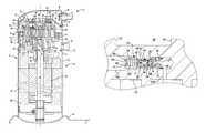
- FIG. 1is a cross-sectional view of a compressor incorporating a thermally-responsive injector constructed in accordance with the principles of the present disclosure, the thermally-responsive injector shown in a deactivated position inhibiting the injection of fluid;
- FIG. 2Ais a cross-sectional view of the thermally-responsive injector of FIG. 1 in the deactivated position, inhibiting the injection of fluid;
- FIG. 2Bis a cross-sectional view of the thermally-responsive injector of FIG. 1 in an activated position, allowing the injection of fluid;
- FIG. 3Ais a cross-sectional view of another thermally-responsive injector in a deactivated position, inhibiting the injection of fluid;
- FIG. 3Bis a cross-sectional view of the thermally-responsive injector of FIG. 3A in an activated position, allowing the injection of fluid;
- FIG. 4is a cross-sectional view of a portion of a compressor of another construction, incorporating a responsive injector constructed in accordance with the principles of the present disclosure.
- a compressor 10is shown as a hermetic scroll refrigerant-compressor of the low side type, i.e., where the motor and compressor are cooled by suction gas in the hermetic shell, as illustrated in the vertical section shown in FIG. 1 .
- the compressor 10may include a hermetic shell assembly 12 , a main bearing housing assembly 14 , a motor assembly 16 , a compression mechanism 18 , a seal assembly 20 , a refrigerant discharge fitting 22 , a discharge valve assembly 24 , a suction gas inlet fitting 26 , and an injection system 27 .
- the shell assembly 12may house the main bearing housing assembly 14 , the motor assembly 16 , and the compression mechanism 18 .
- the shell assembly 12may generally form a compressor housing and may include a cylindrical shell 28 , an end cap 30 at the upper end thereof, a transversely extending partition 32 , and a base 34 at a lower end thereof.
- the end cap 30 and the partition 32may generally define a discharge chamber 36
- the cylindrical shell 28 , the partition 32 , and the base 34may generally define a suction chamber 37 .
- the discharge chamber 36may generally form a discharge muffler for the compressor 10 .
- the refrigerant discharge fitting 22may be attached to the shell assembly 12 at the opening 38 in the end cap 30 .
- the discharge valve assembly 24may be located within the discharge fitting 22 and may generally prevent a reverse flow condition.
- the suction gas inlet fitting 26may be attached to the shell assembly 12 at the opening 40 , such that the suction gas inlet fitting 26 is in fluid communication with the suction chamber 37 .
- the partition 32may include a discharge passage 46 therethrough that provides communication between the compression mechanism 18 and the discharge chamber 36 .
- the main bearing housing assembly 14may be affixed to the shell 28 at a plurality of points in any desirable manner, such as staking.
- the main bearing housing assembly 14may include a main bearing housing 52 , a first bearing 54 disposed therein, bushings 55 , and fasteners 57 .
- the main bearing housing 52may include a central body portion 56 having a series of arms 58 that extend radially outwardly therefrom.
- the central body portion 56may include first and second portions 60 and 62 having an opening 64 extending therethrough.
- the second portion 62may house the first bearing 54 therein.
- the first portion 60may define an annular flat thrust bearing surface 66 on an axial end surface thereof.
- the arm 58may include apertures 70 extending therethrough that receive the fasteners 57 .
- the motor assembly 16may generally include a motor stator 76 , a rotor 78 , and a drive shaft 80 . Windings 82 may pass through the motor stator 76 .
- the motor stator 76may be press-fit into the shell 28 .
- the drive shaft 80may be rotatably driven by the rotor 78 .
- the rotor 78may be press-fit on the drive shaft 80 .
- the drive shaft 80may include an eccentric crank pin 84 having a flat 86 thereon.
- the compression mechanism 18may generally include an orbiting scroll 104 and a non-orbiting scroll 106 .
- the orbiting scroll 104may include an endplate 108 having a spiral vane or wrap 110 on the upper surface thereof and an annular flat thrust surface 112 on the lower surface.
- the thrust surface 112may interface with the annular flat thrust bearing surface 66 on the main bearing housing 52 .
- a cylindrical hub 114may project downwardly from the thrust surface 112 and may have a drive bushing 116 rotatably disposed therein.
- the drive bushing 116may include an inner bore in which the crank pin 84 is drivingly disposed.
- the crank pin flat 86may drivingly engage a flat surface in a portion of the inner bore of the drive bushing 116 to provide a radially compliant driving arrangement.
- An Oldham coupling 117may be engaged with the orbiting and non-orbiting scrolls 104 , 106 to prevent relative rotation therebetween.
- the non-orbiting scroll 106may include an endplate 118 having a spiral wrap 120 on a lower surface 119 thereof and a series of radially outwardly extending flanged portions 121 .
- the spiral wrap 120may form a meshing engagement with the wrap 110 of the orbiting scroll 104 , thereby creating compression pockets, including an inlet pocket 122 , intermediate pockets 124 , 126 , 128 , 130 , and an outlet pocket 132 .
- the non-orbiting scroll 106may be axially displaceable relative to the main bearing housing assembly 14 , the shell assembly 12 , and the orbiting scroll 104 .
- the non-orbiting scroll 106may include a discharge passage 134 in communication with the outlet pocket 132 and an upwardly open recess 136 .
- the upwardly open recess 136may be in fluid communication with the discharge chamber 36 via the discharge passage 46 in the partition 32 .
- the endplate 118may include an injection passage 135 .
- the injection passage 135may be in fluid communication with a cooling fluid source (not shown) and with one or more of the intermediate pockets 124 , 126 , 128 , 130 .
- the injection passage 135may include a radially-extending portion 135 a formed in a radially outer surface 139 of the endplate 118 , and an axially extending portion 135 b formed in the lower surface 119 of the endplate 118 .
- the axially extending portion 135 bmay couple the radially-extending portion 135 a to one or more of the intermediate pockets 124 , 126 , 128 , 130 for fluid communication therebetween.
- the radially-extending portion 135 amay couple the axially extending portion 135 b to the cooling fluid source (not shown) for fluid communication therebetween.
- the flanged portions 121may include openings 137 therethrough. Each opening 137 may receive a bushing 55 therein. The respective bushings 55 may receive fasteners 57 . The fasteners 57 may be engaged with the main bearing housing 52 and the bushings 55 may generally form a guide for axial displacement of the non-orbiting scroll 106 . The fasteners 57 may additionally prevent rotation of the non-orbiting scroll 106 relative to the main bearing housing assembly 14 .
- the non-orbiting scroll 106may include an annular recess 138 in the upper surface thereof defined by parallel and coaxial inner and outer sidewalls 140 , 142 .
- the seal assembly 20may be located within the annular recess 138 .
- the seal assembly 20may be axially displaceable within the annular recess 138 relative to the shell assembly 12 and/or the non-orbiting scroll 106 to provide for axial displacement of the non-orbiting scroll 106 while maintaining a sealed engagement with the partition 32 to isolate the discharge chamber 36 from the suction chamber 37 .
- pressure within the annular recess 138may urge the seal assembly 20 into engagement with the partition 32 , and the spiral wrap 120 of the non-orbiting scroll 106 into engagement with the endplate 108 of the orbiting scroll 104 , during normal compressor operation.
- the injection system 27may include a valve assembly 150 and a conduit 151 .
- the valve assembly 150may be disposed within the injection passage 135 .
- the valve assembly 150may be at least partially disposed within the radially extending portion 135 a of the injection passage 135 .
- the conduit 151may include a first end 153 in fluid communication with the injection passage 135 and a second end 155 in fluid communication with the cooling fluid source.
- the cooling fluid sourcemay be disposed external to the shell assembly 12 and the second end 155 may extend through the cylindrical shell 28 .
- the valve assembly 150may include a housing 152 , a valve body 154 , a first biasing member 156 , and a second biasing member 158 .
- the housing 152may include a generally hollow construction extending from a first end 160 to a second end 162 .
- the first end 160may define a fluid inlet 164 and the second end 162 may define a fluid outlet 166 such that the generally hollow housing 152 defines a flow passage 168 extending from the first end 160 to the second end 162 .
- the first end 160may include a first radially inwardly extending flange 170
- the second end 162may include a second radially inwardly extending flange 172 .
- the first and second flanges 170 , 172may define the fluid inlet and outlet 164 , 166 , respectively.
- the first end 160may be proximal to the conduit 151
- the second end 162may be distal to the conduit 151 .
- the housing 152may be disposed within the injection passage 135 such that the housing 152 is coupled to the non-orbiting scroll 106 .
- the housing 152may be secured to the non-orbiting scroll 106 through a press-fit configuration within the injection passage 135 .
- the first end 160 of the housing 152may be disposed between the outer surface 139 of the endplate 118 and the second end 162 of the housing 152 , such that the inlet 164 is in fluid communication with the conduit 151 .
- the second end 162 of the housing 152may be disposed adjacent to the axially extending portion 135 b of the injection passage 135 , such that the outlet 166 is configured to fluidly communicate with the injection passage 135 and with one or more of the intermediate pockets 124 , 126 , 128 , 130 .
- the valve body 154may include a head 176 , a stem 178 , and a guide 180 .
- the stem 178may extend between the head 176 and the guide 180 , such that a cross section of the valve body 154 defines a generally I-shaped construct.
- the stem 178 and the guide 180may be translatably disposed within the flow passage 168 of the housing 152 .
- the valve body 154may be translatable between a closed position ( FIG. 2A ) and an open position ( FIG. 2B ) within the flow passage 168 . As illustrated in FIG.
- the head 176in the closed position, may sealingly engage the second end 162 of the housing 152 to inhibit fluid communication between the conduit 151 and one or more of the intermediate pockets 124 , 126 , 128 , 130 .
- the head 176in the open position, may be spaced apart from the second end 162 of the housing 152 to allow fluid communication between the conduit 151 and one of the intermediate pockets 124 , 126 , 128 , 130 via the flow passage 168 and the injection passage 135 .
- the guide 180may extend radially outwardly from the stem 178 , such that, in the assembled configuration, the guide 180 engages the housing 152 . Accordingly, a first side 182 of the guide 180 may face a first portion 168 a of the flow passage 168 , and a second side 184 (opposite the first side 182 ) of the guide 180 may face a second portion 168 b of the flow passage 168 . The first portion 168 a of the flow passage 168 may be proximal to the first end 160 and the second portion 168 b of the flow passage 168 may be distal to the first end 160 .
- the guide 180may further include one or more apertures 186 extending from the first side 182 to the second side 184 , and in fluid communication with the first and second portions 168 a , 168 b of the flow passage 168 .
- the first biasing member 156may be a spring that may include a helical construct disposed within the first portion 168 a of the passage 168 , such that the first biasing member 156 biasingly engages the housing 152 and the valve body 154 .
- the first biasing member 156may engage the first flange 170 and the first side 182 of the guide 180 , such that the first biasing member 156 biases the valve body 154 toward the open position ( FIG. 2B ).
- the first biasing member 156may include a material having shape-memory characteristics.
- the first biasing member 156may be formed from a thermally-responsive shape memory material that changes shape, or otherwise activates, in response to a change in temperature.
- the first biasing member 156may be formed from a shape memory material that is thermally responsive at a predetermined threshold temperature.
- the predetermined threshold temperaturemay be between 30 degrees Celsius and 150 degrees Celsius.
- the first biasing member 156may be formed from a shape memory material that is thermally responsive at a predetermined threshold temperature of approximately 200 degrees Celsius.
- the first biasing member 156may be formed from a bi- or tri-metal shape memory alloy such as a copper-zinc-aluminum alloy, a copper-aluminum-nickel alloy, an iron-manganese-silicon alloy, a nickel-aluminum alloy, or a nickel-titanium (nitinol).
- a bi- or tri-metal shape memory alloysuch as a copper-zinc-aluminum alloy, a copper-aluminum-nickel alloy, an iron-manganese-silicon alloy, a nickel-aluminum alloy, or a nickel-titanium (nitinol).
- the second biasing member 158may be a spring that may include a helical construct disposed within the second portion 168 b of the passage 168 , such that the second biasing member 158 biasingly engages the housing 152 and the valve body 154 .
- the second biasing member 158may engage the second flange 172 and the second side 184 of the guide 180 , such that the second biasing member 158 biases the valve body 154 toward the closed position ( FIG. 2A ).
- the first biasing member 156may apply a first force F 1 on the guide 180
- the second biasing member 158may apply a second force F 2 (opposite the first force F 1 ) on the guide 180 .
- the first force F 1may be less than the second force F 2 such that the valve body 154 is biased into the closed position ( FIG. 2A ).
- the compressor 10may operate under what is considered desirable operating temperature conditions when the valve body 154 is in the closed position.
- the temperature of the first biasing member 156may increase as a result of the increased operating temperature of the compressor 10 .
- the first biasing member 156may activate such that the first force F 1 exceeds the second force F 2 , and the valve body 154 is biased into the open position ( FIG. 2B ).
- the valve body 154allows the cooling fluid source to inject a cooling fluid into one or more of the intermediate pockets 124 , 126 , 128 , 130 through the conduit 151 and injection passage 135 , in order to reduce the temperature of the fluid within the intermediate pocket(s) 124 , 126 , 128 , 130 .
- the injection of the cooling fluidreduces the temperature of the compression mechanism 18 and allows the compressor 10 to operate at what is considered a desirable operating temperature.
- the injection of cooling fluid through the conduit 151 and the passage 135 , and the operation of the compressor 10 at a reduced temperature condition,will reduce the temperature of the first biasing member 156 .
- the first biasing member 156may deactivate such that first force F 1 is less than the second force F 2 . Accordingly, the first biasing member 156 may return to the configuration illustrated in FIG. 2A , such that the compressor 10 resumes operation under what is considered a desirable operating temperature condition.
- valve assembly 350may be used with the injection system 27 and/or the method described above.
- the valve assembly 350may be substantially similar to the valve assembly 150 , apart from any exceptions described below and/or shown in the Figures. Therefore, the structure and/or function of similar features will not be described again in detail, and like reference numerals may be used to describe like features and components.
- the valve assembly 350may include a housing 352 , a valve body 354 , the first biasing member 156 , and the second biasing member 158 .
- the housing 352may include a generally cylindrical sidewall 355 extending from a first end 360 to a second end 362 , such that the sidewall 355 defines a flow passage 368 extending from the first end 360 of the housing 352 .
- the first end 360may define a fluid inlet 364 .
- the first end 360may include a first radially inwardly extending flange 370 defining the fluid inlet 364 .
- the sidewall 355may include one or more apertures 366 defining a fluid outlet between the first and second ends 360 , 362 of the housing 352 .
- the housing 352may be disposed within the injection passage 135 such that the housing 352 is coupled to the non-orbiting scroll 106 . In some configurations, the housing 352 may be secured to the non-orbiting scroll 106 through a press-fit configuration within the injection passage 135 . In the assembled configuration, the first end 360 of the housing 352 may be disposed between the outer surface 139 of the endplate 118 and the second end 362 of the housing 352 , such that the inlet 364 is in fluid communication with the conduit 151 .
- the apertures 366may be aligned with the axially extending portion 135 b of the passage, such that the apertures 366 are configured to fluidly communicate with one or more of the intermediate pockets 124 , 126 , 128 , 130 .
- the valve body 354may include a head 376 , a stem 378 , and a guide 380 , and may be translatably disposed within the flow passage 368 of the housing 352 .
- the valve body 354may be translatable between a closed position ( FIG. 3A ) and an open position ( FIG. 3B ) within the flow passage 368 .
- the head 376may include a generally cylindrical sidewall 390 extending from a first end 392 to a second end 394 .
- the first end 392may include an inlet 396 .
- the inlet 396may be concentrically aligned, and in fluid communication, with the fluid inlet 364 of the housing 352 .
- the inlet 396may include a first diameter D 1
- the fluid inlet 364may include a second diameter D 2 that is less than the first diameter D 1 .
- the guide 380may extend from the second end 394 of the head 376 , and may include an inlet 398 (e.g., an aperture) and an outlet 400 (e.g., an aperture).
- the inlet 398may be concentrically aligned, and in fluid communication with, the inlet 396 of the head 376 .
- the inlet 398may include a third diameter D 3 that is less than the first diameter D 1 .
- the outlet 400may be in fluid communication with, and extend in a direction generally perpendicular to, the inlet 398 .
- the inlet 396may extend in an axial direction, while the outlet(s) 400 may extend in a radial direction.
- the guide 380may include more than one outlet 400 .
- the head 376 and/or the guide 380engages the housing 352 , such that the guide 380 may define a first portion 368 a and a second portion 368 b of the flow passage 368 .
- the first portion 368 amay be proximal to the first end 360
- the second portion 368 bmay be distal to the first end 360 .
- the stem 378may engage the second end 362 of the housing 352 , and the head 376 and/or the guide 380 may sealingly engage the sidewall 355 of the housing 352 to close the apertures 366 and inhibit fluid communication between the outlet(s) 400 (and, thus, the conduit 151 ) and one or more of the intermediate pockets 124 , 126 , 128 , 130 .
- the first end 392 of the head 376may engage the flange 370 of the housing 352 , such that the outlets 400 are aligned, and in fluid communication, with the outlet 366 and one or more of the intermediate pockets 124 , 126 , 128 , 130 .
- valve body 354allows fluid communication between the conduit 151 and one or more of the intermediate pockets 124 , 126 , 128 , 130 via the flow passage 368 and the injection passage 135 .
- the first biasing member 156may be disposed within the second portion 368 b of the passage 368 , such that the first biasing member 156 biasingly engages the housing 352 and the valve body 354 .
- the first biasing member 156may surround the stem 378 , and engage the guide 380 and the second end 362 of the housing 352 , such that the first biasing member 156 biases the valve body 354 toward the open position ( FIG. 3B ).
- the second biasing member 158may be disposed within the first portion 368 a of the passage 368 , such that the second biasing member 158 biasingly engages the housing 352 and the valve body 354 .
- the sidewall 390 of the head 376may surround the second biasing member 158 , such that the second biasing member 158 engages the first flange 370 and the guide 380 .
- the second biasing member 158biases the valve body 354 toward the closed position ( FIG. 3A ).
- a compressor 10 ′ of a second constructionis illustrated.
- the compressor 10 ′can be similar to the compressor 10 ( FIGS. 1-3B ), except as otherwise shown or described herein. Aspects of the compressor 10 ′ that are denoted with primed reference numerals are similar to aspects of the compressor 10 ( FIGS. 1-3B ) that have similarly numbered, but non-primed reference numerals, except as otherwise shown or described herein.
- the injection system 27 ′can further include a control module 410 and a temperature sensor 414 .
- the control module 410may control the operation of a valve assembly 150 ′ based on an operating temperature of the compressor 10 ′.
- the valve assembly 150 ′can be similar to the valve assembly 150 ( FIGS. 1-2B ) except as otherwise shown or described herein.
- the temperature sensor 414may sense an operating temperature of the compressor 10 ′. When the operating temperature exceeds a threshold operating temperature, the control module 410 may control the shape memory characteristics of the first biasing member 156 ′ to change the first biasing member 156 ′ from a deactivated state (e.g., similar to FIG. 2A ) to an activated state (e.g., similar to FIG. 2B ). Even though the control module 410 is shown external to the compressor, it should be understood that the control module 410 could be located internal to the compressor along with the temperature sensor 414 . It should also be understood that the control module 410 and the temperature sensor 414 could be a single mechanism that can detect temperature and cause the first biasing member 156 ′ to activate its shape memory characteristics to change states.
- the control module 410may activate the first biasing member 156 ′ in response to a signal received from the temperature sensor 414 .
- the control module 410may provide an electrical current to the first biasing member 156 ′.
- the electrical currentmay activate the thermally-responsive or shape-memory characteristics of the first biasing member 156 ′.
- the electrical currentmay increase the temperature of the first biasing member 156 ′
- the first biasing member 156 ′may activate (e.g., similar to FIG. 2B ).
- the control module 410removes the electrical current from the first biasing member 156 ′ in order to reduce the temperature of the first biasing member 156 ′, such that the first biasing member 156 ′ returns to the deactivated position (e.g., similar to FIG. 2A ).
- the first biasing member 156 ′may be a piezoelectric material and the electric current may cause the first biasing member 156 ′ to activate its piezoelectric shape memory characteristics to axially displace the valve body 154 ′ (e.g., similar to FIG. 2B ).
- the control module 410removes the electrical current from the first biasing member 156 ′ in order to return the first biasing member 156 ′ to the deactivated position (e.g., similar to FIG. 2A ).
- the first biasing member 156 ′may be a magnetic shape memory material and the control module 410 may provide a magnetic field to the first biasing member 156 ′.
- the magnetic fieldmay cause the first biasing member 156 ′ to activate its magnetic shape memory characteristics to axially displace the valve body 154 ′ (e.g., similar to FIGS. 2B ).
- the control module 410removes the magnetic field from the first biasing member 156 ′ in order to return the first biasing member 156 ′ to the deactivated position (e.g., similar to FIG. 2A ).
- valve assembly 150 ′is shown and described as similar to the valve assembly 150 ( FIGS. 1-2B ), the valve assembly 150 ′ can be constructed similar to the valve assembly 350 ( FIGS. 3A-3B , and described above).
- Example embodimentsare provided so that this disclosure will be thorough, and will fully convey the scope to those who are skilled in the art. Numerous specific details are set forth such as examples of specific components, devices, and methods, to provide a thorough understanding of embodiments of the present disclosure. It will be apparent to those skilled in the art that specific details need not be employed, that example embodiments may be embodied in many different forms and that neither should be construed to limit the scope of the disclosure. In some example embodiments, well-known processes, well-known device structures, and well-known technologies are not described in detail.
- first, second, third, etc.may be used herein to describe various elements, components, regions, layers and/or sections, these elements, components, regions, layers and/or sections should not be limited by these terms. These terms may be only used to distinguish one element, component, region, layer or section from another region, layer or section. Terms such as “first,” “second,” and other numerical terms when used herein do not imply a sequence or order unless clearly indicated by the context. Thus, a first element, component, region, layer or section discussed below could be termed a second element, component, region, layer or section without departing from the teachings of the example embodiments.
- Spatially relative termssuch as “inner,” “outer,” “beneath,” “below,” “lower,” “above,” “upper,” and the like, may be used herein for ease of description to describe one element or feature's relationship to another element(s) or feature(s) as illustrated in the figures. Spatially relative terms may be intended to encompass different orientations of the device in use or operation in addition to the orientation depicted in the figures. For example, if the device in the figures is turned over, elements described as “below” or “beneath” other elements or features would then be oriented “above” the other elements or features. Thus, the example term “below” can encompass both an orientation of above and below. The device may be otherwise oriented (rotated 90 degrees or at other orientations) and the spatially relative descriptors used herein interpreted accordingly.
Landscapes
- Engineering & Computer Science (AREA)
- General Engineering & Computer Science (AREA)
- Mechanical Engineering (AREA)
- Applications Or Details Of Rotary Compressors (AREA)
- Rotary Pumps (AREA)
Abstract
Description
Claims (14)
Priority Applications (3)
| Application Number | Priority Date | Filing Date | Title |
|---|---|---|---|
| US15/186,151US10598180B2 (en) | 2015-07-01 | 2016-06-17 | Compressor with thermally-responsive injector |
| CN201610512702.7ACN106321430B (en) | 2015-07-01 | 2016-06-30 | Compressor and valve module |
| CN201620688616.7UCN205876713U (en) | 2015-07-01 | 2016-06-30 | Compressor and valve module |
Applications Claiming Priority (2)
| Application Number | Priority Date | Filing Date | Title |
|---|---|---|---|
| US201562187443P | 2015-07-01 | 2015-07-01 | |
| US15/186,151US10598180B2 (en) | 2015-07-01 | 2016-06-17 | Compressor with thermally-responsive injector |
Publications (2)
| Publication Number | Publication Date |
|---|---|
| US20170002818A1 US20170002818A1 (en) | 2017-01-05 |
| US10598180B2true US10598180B2 (en) | 2020-03-24 |
Family
ID=57683502
Family Applications (1)
| Application Number | Title | Priority Date | Filing Date |
|---|---|---|---|
| US15/186,151Active2037-04-11US10598180B2 (en) | 2015-07-01 | 2016-06-17 | Compressor with thermally-responsive injector |
Country Status (2)
| Country | Link |
|---|---|
| US (1) | US10598180B2 (en) |
| CN (2) | CN205876713U (en) |
Cited By (1)
| Publication number | Priority date | Publication date | Assignee | Title |
|---|---|---|---|---|
| US12098724B2 (en)* | 2022-09-06 | 2024-09-24 | Lg Electronics Inc. | Scroll compressor |
Families Citing this family (24)
| Publication number | Priority date | Publication date | Assignee | Title |
|---|---|---|---|---|
| US7988433B2 (en) | 2009-04-07 | 2011-08-02 | Emerson Climate Technologies, Inc. | Compressor having capacity modulation assembly |
| US9651043B2 (en) | 2012-11-15 | 2017-05-16 | Emerson Climate Technologies, Inc. | Compressor valve system and assembly |
| US9249802B2 (en) | 2012-11-15 | 2016-02-02 | Emerson Climate Technologies, Inc. | Compressor |
| US9989057B2 (en) | 2014-06-03 | 2018-06-05 | Emerson Climate Technologies, Inc. | Variable volume ratio scroll compressor |
| US9790940B2 (en) | 2015-03-19 | 2017-10-17 | Emerson Climate Technologies, Inc. | Variable volume ratio compressor |
| US10598180B2 (en) | 2015-07-01 | 2020-03-24 | Emerson Climate Technologies, Inc. | Compressor with thermally-responsive injector |
| US10378542B2 (en) | 2015-07-01 | 2019-08-13 | Emerson Climate Technologies, Inc. | Compressor with thermal protection system |
| US10378540B2 (en) | 2015-07-01 | 2019-08-13 | Emerson Climate Technologies, Inc. | Compressor with thermally-responsive modulation system |
| CN207377799U (en) | 2015-10-29 | 2018-05-18 | 艾默生环境优化技术有限公司 | Compressor |
| US10890186B2 (en) | 2016-09-08 | 2021-01-12 | Emerson Climate Technologies, Inc. | Compressor |
| US10801495B2 (en) | 2016-09-08 | 2020-10-13 | Emerson Climate Technologies, Inc. | Oil flow through the bearings of a scroll compressor |
| US10753352B2 (en) | 2017-02-07 | 2020-08-25 | Emerson Climate Technologies, Inc. | Compressor discharge valve assembly |
| US11022119B2 (en) | 2017-10-03 | 2021-06-01 | Emerson Climate Technologies, Inc. | Variable volume ratio compressor |
| WO2019115112A1 (en)* | 2017-12-12 | 2019-06-20 | Jt International Sa | Fluid supply system for an electronic cigarette |
| US10962008B2 (en) | 2017-12-15 | 2021-03-30 | Emerson Climate Technologies, Inc. | Variable volume ratio compressor |
| US10995753B2 (en) | 2018-05-17 | 2021-05-04 | Emerson Climate Technologies, Inc. | Compressor having capacity modulation assembly |
| CN112983782B (en)* | 2019-12-02 | 2024-03-12 | 贝尔运动股份有限公司 | Multi-valve pump head |
| US11655813B2 (en) | 2021-07-29 | 2023-05-23 | Emerson Climate Technologies, Inc. | Compressor modulation system with multi-way valve |
| US12259163B2 (en) | 2022-06-01 | 2025-03-25 | Copeland Lp | Climate-control system with thermal storage |
| US11846287B1 (en) | 2022-08-11 | 2023-12-19 | Copeland Lp | Scroll compressor with center hub |
| US11965507B1 (en) | 2022-12-15 | 2024-04-23 | Copeland Lp | Compressor and valve assembly |
| US12416308B2 (en) | 2022-12-28 | 2025-09-16 | Copeland Lp | Compressor with shutdown assembly |
| US12173708B1 (en) | 2023-12-07 | 2024-12-24 | Copeland Lp | Heat pump systems with capacity modulation |
| US12163523B1 (en) | 2023-12-15 | 2024-12-10 | Copeland Lp | Compressor and valve assembly |
Citations (134)
| Publication number | Priority date | Publication date | Assignee | Title |
|---|---|---|---|---|
| GB2107829A (en) | 1981-06-09 | 1983-05-05 | Dudley Vernon Steynor | Thermostatic valves, and solar water heating systems incorporating the same |
| US4466784A (en) | 1981-03-03 | 1984-08-21 | Sanden Corporation | Drive mechanism for a scroll type fluid displacement apparatus |
| US4475360A (en) | 1982-02-26 | 1984-10-09 | Hitachi, Ltd. | Refrigeration system incorporating scroll type compressor |
| US4475875A (en) | 1981-10-12 | 1984-10-09 | Sanden Corporation | Scroll type fluid displacement apparatus with balance weight |
| US4547138A (en) | 1983-03-15 | 1985-10-15 | Sanden Corporation | Lubricating mechanism for scroll-type fluid displacement apparatus |
| US4552518A (en) | 1984-02-21 | 1985-11-12 | American Standard Inc. | Scroll machine with discharge passage through orbiting scroll plate and associated lubrication system |
| US4564339A (en) | 1983-06-03 | 1986-01-14 | Mitsubishi Denki Kabushiki Kaisha | Scroll compressor |
| US4580949A (en) | 1984-03-21 | 1986-04-08 | Matsushita Electric Industrial Co., Ltd. | Sliding vane type rotary compressor |
| US4650405A (en) | 1984-12-26 | 1987-03-17 | Nippon Soken, Inc. | Scroll pump with axially spaced pumping chambers in series |
| JPS62220789A (en) | 1986-03-20 | 1987-09-28 | Chiyoda Chem Eng & Constr Co Ltd | High temperature water automatic supply stop device |
| US4824344A (en) | 1986-11-05 | 1989-04-25 | Mitsubishi Denki Kabushiki Kaisha | Scroll-type compressor with oil passageway in thrust bearing |
| US4838773A (en) | 1986-01-10 | 1989-06-13 | Sanyo Electric Co., Ltd. | Scroll compressor with balance weight movably attached to swing link |
| US4842499A (en) | 1986-09-24 | 1989-06-27 | Mitsubishi Denki Kabushiki Kaish A | Scroll-type positive displacement apparatus with oil supply to compression chamber |
| US4886433A (en) | 1987-06-15 | 1989-12-12 | Agintec Ag | Displacement machine having spiral chamber and displacement member of increasing radial widths |
| US4898520A (en) | 1988-07-18 | 1990-02-06 | United Technologies Corporation | Method of and arrangement for reducing bearing loads in scroll compressors |
| JPH0281982A (en) | 1988-09-20 | 1990-03-22 | Matsushita Refrig Co Ltd | Scroll compressor |
| US4940395A (en) | 1987-12-08 | 1990-07-10 | Sanden Corporation | Scroll type compressor with variable displacement mechanism |
| US4954057A (en) | 1988-10-18 | 1990-09-04 | Copeland Corporation | Scroll compressor with lubricated flat driving surface |
| US4990071A (en) | 1988-05-12 | 1991-02-05 | Sanden Corporation | Scroll type fluid apparatus having two orbiting end plates linked together |
| US5024589A (en) | 1988-08-03 | 1991-06-18 | Asea Brown Boveri Ltd. | Spiral displacement machine having a lubricant system |
| US5040958A (en) | 1988-04-11 | 1991-08-20 | Hitachi, Ltd. | Scroll compressor having changeable axis in eccentric drive |
| US5040952A (en) | 1989-02-28 | 1991-08-20 | Kabushiki Kaisha Toshiba | Scroll-type compressor |
| JPH03233101A (en) | 1990-02-08 | 1991-10-17 | Mitsubishi Heavy Ind Ltd | Scroll type fluid machine |
| US5059098A (en) | 1989-02-02 | 1991-10-22 | Kabushiki Kaisha Toyoda Jidoshokki Seisakusho | Apparatus for varying capacity of scroll type compressor |
| US5098265A (en) | 1989-04-20 | 1992-03-24 | Hitachi, Ltd. | Oil-free scroll fluid machine with projecting orbiting bearing boss |
| JPH04121478A (en) | 1990-09-12 | 1992-04-22 | Toshiba Corp | scroll compressor |
| US5145346A (en) | 1990-12-06 | 1992-09-08 | Mitsubishi Jukogyo Kabushiki Kaisha | Scroll type fluid machinery having a tilt regulating member |
| JPH04272490A (en) | 1990-10-01 | 1992-09-29 | Copeland Corp | Scroll type compressor |
| US5152682A (en) | 1990-03-29 | 1992-10-06 | Kabushiki Kaisha Toshiba | Scroll type fluid machine with passageway for innermost working chamber |
| US5171141A (en) | 1990-10-01 | 1992-12-15 | Kabushiki Kaisha Toshiba | Scroll compressor with distal ends of the wraps having sliding contact on curved portions |
| USRE34148E (en) | 1985-06-18 | 1992-12-22 | Sanden Corporation | Scroll type compressor with variable displacement mechanism |
| US5199862A (en) | 1990-07-24 | 1993-04-06 | Mitsubishi Jukogyo Kabushiki Kaisha | Scroll type fluid machinery with counter weight on drive bushing |
| US5213489A (en) | 1989-11-02 | 1993-05-25 | Matsushita Electric Industrial Co., Ltd. | Scroll compressor with axial vibration prevention for a shaft bearing |
| US5304047A (en) | 1991-08-30 | 1994-04-19 | Daikin Industries, Ltd. | Scroll compressor of two-stage compression type having an improved volumetric efficiency |
| US5318424A (en) | 1992-12-07 | 1994-06-07 | Carrier Corporation | Minimum diameter scroll component |
| US5330463A (en)* | 1990-07-06 | 1994-07-19 | Mitsubishi Jukogyo Kabushiki Kaisha | Scroll type fluid machinery with reduced pressure biasing the stationary scroll |
| US5336068A (en) | 1991-06-12 | 1994-08-09 | Mitsubishi Denki Kabushiki Kaisha | Scroll-type fluid machine having the eccentric shaft inserted into the moving scroll |
| US5340287A (en) | 1989-11-02 | 1994-08-23 | Matsushita Electric Industrial Co., Ltd. | Scroll-type compressor having a plate preventing excess lift of the crankshaft |
| JPH0726618B2 (en) | 1986-11-28 | 1995-03-29 | 三井精機工業株式会社 | Scroll compressor |
| US5411384A (en) | 1986-08-22 | 1995-05-02 | Copeland Corporation | Scroll compressor having upper and lower bearing housings and a method of testing and assembling the compressor |
| US5425626A (en) | 1992-09-11 | 1995-06-20 | Hitachi, Ltd. | Scroll type fluid machine with an involute spiral based on a circle having a varying radius |
| US5427512A (en) | 1991-12-20 | 1995-06-27 | Hitachi, Ltd. | Scroll fluid machine, scroll member and processing method thereof |
| US5451146A (en) | 1992-04-01 | 1995-09-19 | Nippondenso Co., Ltd. | Scroll-type variable-capacity compressor with bypass valve |
| US5458472A (en) | 1992-10-28 | 1995-10-17 | Kabushiki Kaisha Toyoda Jidoshokki Seisakusho | Scroll type compressor having thrust regulation on the eccentric shaft |
| US5458471A (en) | 1992-08-14 | 1995-10-17 | Ni; Shimao | Scroll-type fluid displacement device having high built-in volume ratio and semi-compliant biasing mechanism |
| DE3917656C2 (en) | 1988-06-29 | 1995-11-16 | American Standard Inc | Scroll compressor |
| US5547354A (en) | 1993-12-02 | 1996-08-20 | Kabushiki Kaisha Toyoda Jidoshokki Seisakusho | Scroll compressor balancing |
| US5557897A (en) | 1992-02-20 | 1996-09-24 | Braas Gmbh | Fastening device for a roof sealing strip or the like |
| JPH08320079A (en) | 1995-05-24 | 1996-12-03 | Piolax Inc | Flow control valve |
| CN1137614A (en) | 1995-06-07 | 1996-12-11 | 科普兰公司 | Power modulation scroll machine |
| US5607288A (en) | 1993-11-29 | 1997-03-04 | Copeland Corporation | Scroll machine with reverse rotation protection |
| US5624247A (en) | 1994-06-17 | 1997-04-29 | Nakamura; Mitsuo | Balance type scroll fluid machine |
| US5649817A (en) | 1995-11-24 | 1997-07-22 | Kabushiki Kaisha Yasunaga | Scroll type fluid machine having first and second bearings for the driving shaft |
| US5775893A (en) | 1995-06-20 | 1998-07-07 | Hitachi, Ltd. | Scroll compressor having an orbiting scroll with volute wraps on both sides of a plate |
| US5842843A (en) | 1995-11-30 | 1998-12-01 | Anest Iwata Corporation | Scroll fluid machine having a cooling passage inside the drive shaft |
| FR2764347A1 (en) | 1997-06-05 | 1998-12-11 | Alsthom Cge Alcatel | SCROLL TYPE MACHINE |
| US5855475A (en) | 1995-12-05 | 1999-01-05 | Matsushita Electric Industrial Co., Ltd. | Scroll compressor having bypass valves |
| US5938417A (en) | 1995-12-13 | 1999-08-17 | Hitachi, Ltd. | Scroll type fluid machine having wraps formed of circular arcs |
| US6030192A (en) | 1994-12-23 | 2000-02-29 | Bristol Compressors, Inc. | Scroll compressor having bearing structure in the orbiting scroll to eliminate tipping forces |
| JP2000104684A (en) | 1998-09-29 | 2000-04-11 | Nippon Soken Inc | Variable displacement compressor |
| US6068459A (en) | 1998-02-19 | 2000-05-30 | Varian, Inc. | Tip seal for scroll-type vacuum pump |
| US6093005A (en) | 1997-09-12 | 2000-07-25 | Asuka Japan Co., Ltd. | Scroll-type fluid displacement machine |
| US6152714A (en) | 1996-09-20 | 2000-11-28 | Hitachi, Ltd. | Displacement type fluid machine having rotation suppression of an orbiting displacer |
| US6174149B1 (en) | 1999-03-16 | 2001-01-16 | Scroll Technologies | Scroll compressor with captured counterweight |
| CN1286358A (en) | 1999-08-25 | 2001-03-07 | 科普兰公司 | Protection of swirl temp. |
| US6257840B1 (en) | 1999-11-08 | 2001-07-10 | Copeland Corporation | Scroll compressor for natural gas |
| US6264444B1 (en) | 1999-02-02 | 2001-07-24 | Kabushiki Kaisha Toyoda Jidoshokki Seisakusho | Scroll-type compressor having orbital rotating mechanism on the side of movable spiral wall |
| US6280154B1 (en) | 2000-02-02 | 2001-08-28 | Copeland Corporation | Scroll compressor |
| US6290477B1 (en) | 1997-09-16 | 2001-09-18 | Ateliers Busch Sa | Scroll vacuum pump |
| US6293767B1 (en) | 2000-02-28 | 2001-09-25 | Copeland Corporation | Scroll machine with asymmetrical bleed hole |
| US6293776B1 (en) | 2000-07-12 | 2001-09-25 | Scroll Technologies | Method of connecting an economizer tube |
| US6309194B1 (en) | 1997-06-04 | 2001-10-30 | Carrier Corporation | Enhanced oil film dilation for compressor suction valve stress reduction |
| US6338912B1 (en) | 1998-11-18 | 2002-01-15 | Kabushiki Kaisha Toyoda Jidoshokki Seisakusho | Fuel cell system having common scroll type compressor and regenerator |
| US6361890B1 (en) | 1998-11-09 | 2002-03-26 | Kabushiki Kaisha Toyoda Jidoshokki Seisakusho | Fuel cell system having scroll type compressor and regenerator |
| JP2002202074A (en) | 2000-12-28 | 2002-07-19 | Toyota Industries Corp | Scroll type compressor |
| CN1407233A (en) | 2001-08-31 | 2003-04-02 | 三洋电机株式会社 | Vortex compressor and its manufacture |
| JP2003214365A (en) | 2002-01-24 | 2003-07-30 | Copeland Corp | Scroll member for scroll type compressor and manufacturing method therefor |
| US6619062B1 (en) | 1999-12-06 | 2003-09-16 | Daikin Industries, Ltd. | Scroll compressor and air conditioner |
| US6679683B2 (en) | 2000-10-16 | 2004-01-20 | Copeland Corporation | Dual volume-ratio scroll machine |
| US6746223B2 (en) | 2001-12-27 | 2004-06-08 | Tecumseh Products Company | Orbiting rotary compressor |
| US20040170509A1 (en) | 2003-02-27 | 2004-09-02 | Wehrenberg Chris A. | Scroll compressor with bifurcated flow pattern |
| US20040184932A1 (en) | 2003-03-17 | 2004-09-23 | Alexander Lifson | Economizer/by-pass port inserts to control port size |
| US20050019178A1 (en) | 2003-07-26 | 2005-01-27 | Lg Electronics Inc. | Variable capacity scroll compressor |
| US6887051B2 (en) | 2002-02-05 | 2005-05-03 | Matsushita Electric Industrial Co., Ltd. | Scroll air supply apparatus having a motor shaft and a mechanism shaft |
| US6896493B2 (en) | 2002-08-27 | 2005-05-24 | Lg Electronics Inc. | Scroll compressor |
| US20050140232A1 (en) | 2003-12-26 | 2005-06-30 | Lee Deug H. | Motor for washing machine |
| JP2005264827A (en) | 2004-03-18 | 2005-09-29 | Sanden Corp | Scroll compressor |
| CN2747381Y (en) | 2004-07-21 | 2005-12-21 | 南京奥特佳冷机有限公司 | Bypass type variable displacement vortex compressor |
| JP2006083754A (en) | 2004-09-15 | 2006-03-30 | Toshiba Kyaria Kk | Hermetic compressor and refrigeration cycle apparatus |
| JP2006183474A (en) | 2004-12-24 | 2006-07-13 | Toshiba Kyaria Kk | Hermetic electric compressor and refrigeration cycle apparatus |
| CN1828022A (en) | 2005-03-04 | 2006-09-06 | 科普兰公司 | Scroll machinery with single plate floating seals |
| US7172395B2 (en) | 2003-07-28 | 2007-02-06 | Daikin Industries, Ltd. | Scroll-type fluid machine |
| JP2007228683A (en) | 2006-02-22 | 2007-09-06 | Daikin Ind Ltd | Outer rotor type motor |
| US7371059B2 (en) | 2006-09-15 | 2008-05-13 | Emerson Climate Technologies, Inc. | Scroll compressor with discharge valve |
| US20080115357A1 (en) | 2006-11-15 | 2008-05-22 | Li Feng E | Scroll machine having improved discharge valve assembly |
| US20080159893A1 (en) | 2006-12-28 | 2008-07-03 | Copeland Corporation | Thermally compensated scroll machine |
| US20080223057A1 (en) | 2005-10-26 | 2008-09-18 | Alexander Lifson | Refrigerant System with Pulse Width Modulated Components and Variable Speed Compressor |
| WO2009017741A1 (en) | 2007-07-30 | 2009-02-05 | Therm-O-Disc Incorporated | Thermally actuated valve |
| US7510382B2 (en)* | 2004-03-31 | 2009-03-31 | Lg Electronics Inc. | Apparatus for preventing overheating of scroll compressor |
| US20090185935A1 (en) | 2008-01-16 | 2009-07-23 | Seibel Stephen M | Scroll machine |
| US20090191080A1 (en) | 2005-10-26 | 2009-07-30 | Ignatiev Kirill M | Scroll Compressor |
| CN101684785A (en) | 2008-09-24 | 2010-03-31 | 东元电机股份有限公司 | Compressor |
| US7771178B2 (en) | 2006-12-22 | 2010-08-10 | Emerson Climate Technologies, Inc. | Vapor injection system for a scroll compressor |
| US20100209278A1 (en) | 2009-02-17 | 2010-08-19 | Kabushiki Kaisha Toyota Jidoshokki | Scroll-type fluid machine |
| US7815423B2 (en)* | 2005-07-29 | 2010-10-19 | Emerson Climate Technologies, Inc. | Compressor with fluid injection system |
| US20100300659A1 (en) | 2009-05-29 | 2010-12-02 | Stover Robert C | Compressor Having Capacity Modulation Or Fluid Injection Systems |
| US7956501B2 (en) | 2007-10-30 | 2011-06-07 | Lg Electronics Inc. | Motor and washing machine using the same |
| CN102089525A (en) | 2008-05-30 | 2011-06-08 | 艾默生环境优化技术有限公司 | Compressor with output adjustment assembly including piston actuation |
| US20120183422A1 (en) | 2011-01-13 | 2012-07-19 | Visteon Global Technologies, Inc. | Retainer for a stator of an electric compressor |
| DE102011001394A1 (en) | 2011-03-18 | 2012-09-20 | Visteon Global Technologies, Inc. | Electrically driven refrigeration compressor for e.g. stationary application in refrigeration apparatus of electromotor-driven motor car in motor car air conditioning field, has main housing comprising bearing dome in axial direction |
| US8303279B2 (en)* | 2009-09-08 | 2012-11-06 | Danfoss Scroll Technologies, Llc | Injection tubes for injection of fluid into a scroll compressor |
| US8303278B2 (en)* | 2008-07-08 | 2012-11-06 | Tecumseh Products Company | Scroll compressor utilizing liquid or vapor injection |
| CN202926640U (en) | 2012-10-17 | 2013-05-08 | 大连三洋压缩机有限公司 | Automatic liquid spraying structure of scroll compressor |
| US20140134030A1 (en) | 2012-11-15 | 2014-05-15 | Emerson Climate Technologies, Inc. | Compressor valve system and assembly |
| CN203962320U (en) | 2014-06-17 | 2014-11-26 | 广东美芝制冷设备有限公司 | External rotor rotary compressor |
| US8932036B2 (en) | 2010-10-28 | 2015-01-13 | Emerson Climate Technologies, Inc. | Compressor seal assembly |
| US20150037184A1 (en) | 2013-07-31 | 2015-02-05 | Trane International Inc. | Double-ended scroll compressor lubrication of one orbiting scroll bearing via crankshaft oil gallery from another orbiting scroll bearing |
| US20150086404A1 (en) | 2012-03-07 | 2015-03-26 | Lg Electronics Inc. | Horizontal type scroll compressor |
| US20150354719A1 (en) | 2013-01-17 | 2015-12-10 | Danfoss A/S | Shape memory alloy actuator for valve for a vapour compression system |
| US20160025094A1 (en) | 2014-07-28 | 2016-01-28 | Emerson Climate Technologies, Inc. | Compressor motor with center stator |
| CN105317678A (en) | 2014-06-17 | 2016-02-10 | 广东美芝制冷设备有限公司 | External rotor rotary compressor |
| US20170002817A1 (en) | 2015-07-01 | 2017-01-05 | Emerson Climate Technologies, Inc. | Compressor with thermal protection system |
| CN205876713U (en) | 2015-07-01 | 2017-01-11 | 艾默生环境优化技术有限公司 | Compressor and valve module |
| US20170030354A1 (en) | 2015-07-01 | 2017-02-02 | Emerson Climate Technologies, Inc. | Compressor With Thermally-Responsive Modulation System |
| WO2017071641A1 (en) | 2015-10-29 | 2017-05-04 | Emerson Climate Technologies, Inc. | Compressor having capacity modulation system |
| US20170241417A1 (en) | 2016-02-24 | 2017-08-24 | Lg Electronics Inc. | Scroll compressor |
| US20170342984A1 (en) | 2016-05-30 | 2017-11-30 | Lg Electronics Inc. | Scroll compressor |
| US20170342983A1 (en) | 2016-05-25 | 2017-11-30 | Lg Electronics Inc. | Scroll compressor |
| US20180066657A1 (en) | 2016-09-08 | 2018-03-08 | Emerson Climate Technologies, Inc. | Compressor |
| US20180066656A1 (en) | 2016-09-08 | 2018-03-08 | Emerson Climate Technologies, Inc. | Oil Flow Through The Bearings Of A Scroll Compressor |
| US9989057B2 (en) | 2014-06-03 | 2018-06-05 | Emerson Climate Technologies, Inc. | Variable volume ratio scroll compressor |
| US20180223823A1 (en) | 2017-02-07 | 2018-08-09 | Emerson Climate Technologies, Inc. | Compressor Discharge Valve Assembly |
| US10066622B2 (en) | 2015-10-29 | 2018-09-04 | Emerson Climate Technologies, Inc. | Compressor having capacity modulation system |
| US10094380B2 (en) | 2012-11-15 | 2018-10-09 | Emerson Climate Technologies, Inc. | Compressor |
Family Cites Families (3)
| Publication number | Priority date | Publication date | Assignee | Title |
|---|---|---|---|---|
| US2107829A (en)* | 1933-02-18 | 1938-02-08 | Zeiss Ikon Ag Dresden | Photographic camera |
| US7116366B1 (en)* | 1999-08-31 | 2006-10-03 | Micron Technology, Inc. | CMOS aps pixel sensor dynamic range increase |
| US8533283B2 (en)* | 2007-05-03 | 2013-09-10 | Gary Stephen Shuster | Redirection method for electronic content |
- 2016
- 2016-06-17USUS15/186,151patent/US10598180B2/enactiveActive
- 2016-06-30CNCN201620688616.7Upatent/CN205876713U/ennot_activeWithdrawn - After Issue
- 2016-06-30CNCN201610512702.7Apatent/CN106321430B/ennot_activeExpired - Fee Related
Patent Citations (150)
| Publication number | Priority date | Publication date | Assignee | Title |
|---|---|---|---|---|
| US4466784A (en) | 1981-03-03 | 1984-08-21 | Sanden Corporation | Drive mechanism for a scroll type fluid displacement apparatus |
| GB2107829A (en) | 1981-06-09 | 1983-05-05 | Dudley Vernon Steynor | Thermostatic valves, and solar water heating systems incorporating the same |
| US4475875A (en) | 1981-10-12 | 1984-10-09 | Sanden Corporation | Scroll type fluid displacement apparatus with balance weight |
| US4475360A (en) | 1982-02-26 | 1984-10-09 | Hitachi, Ltd. | Refrigeration system incorporating scroll type compressor |
| US4547138A (en) | 1983-03-15 | 1985-10-15 | Sanden Corporation | Lubricating mechanism for scroll-type fluid displacement apparatus |
| US4564339A (en) | 1983-06-03 | 1986-01-14 | Mitsubishi Denki Kabushiki Kaisha | Scroll compressor |
| US4552518A (en) | 1984-02-21 | 1985-11-12 | American Standard Inc. | Scroll machine with discharge passage through orbiting scroll plate and associated lubrication system |
| US4580949A (en) | 1984-03-21 | 1986-04-08 | Matsushita Electric Industrial Co., Ltd. | Sliding vane type rotary compressor |
| US4650405A (en) | 1984-12-26 | 1987-03-17 | Nippon Soken, Inc. | Scroll pump with axially spaced pumping chambers in series |
| USRE34148E (en) | 1985-06-18 | 1992-12-22 | Sanden Corporation | Scroll type compressor with variable displacement mechanism |
| US4838773A (en) | 1986-01-10 | 1989-06-13 | Sanyo Electric Co., Ltd. | Scroll compressor with balance weight movably attached to swing link |
| JPS62220789A (en) | 1986-03-20 | 1987-09-28 | Chiyoda Chem Eng & Constr Co Ltd | High temperature water automatic supply stop device |
| US5411384A (en) | 1986-08-22 | 1995-05-02 | Copeland Corporation | Scroll compressor having upper and lower bearing housings and a method of testing and assembling the compressor |
| US4842499A (en) | 1986-09-24 | 1989-06-27 | Mitsubishi Denki Kabushiki Kaish A | Scroll-type positive displacement apparatus with oil supply to compression chamber |
| US4824344A (en) | 1986-11-05 | 1989-04-25 | Mitsubishi Denki Kabushiki Kaisha | Scroll-type compressor with oil passageway in thrust bearing |
| JPH0726618B2 (en) | 1986-11-28 | 1995-03-29 | 三井精機工業株式会社 | Scroll compressor |
| US4886433A (en) | 1987-06-15 | 1989-12-12 | Agintec Ag | Displacement machine having spiral chamber and displacement member of increasing radial widths |
| US4940395A (en) | 1987-12-08 | 1990-07-10 | Sanden Corporation | Scroll type compressor with variable displacement mechanism |
| US5040958A (en) | 1988-04-11 | 1991-08-20 | Hitachi, Ltd. | Scroll compressor having changeable axis in eccentric drive |
| US4990071A (en) | 1988-05-12 | 1991-02-05 | Sanden Corporation | Scroll type fluid apparatus having two orbiting end plates linked together |
| DE3917656C2 (en) | 1988-06-29 | 1995-11-16 | American Standard Inc | Scroll compressor |
| US4898520A (en) | 1988-07-18 | 1990-02-06 | United Technologies Corporation | Method of and arrangement for reducing bearing loads in scroll compressors |
| US5024589A (en) | 1988-08-03 | 1991-06-18 | Asea Brown Boveri Ltd. | Spiral displacement machine having a lubricant system |
| JPH0281982A (en) | 1988-09-20 | 1990-03-22 | Matsushita Refrig Co Ltd | Scroll compressor |
| US4954057A (en) | 1988-10-18 | 1990-09-04 | Copeland Corporation | Scroll compressor with lubricated flat driving surface |
| US5059098A (en) | 1989-02-02 | 1991-10-22 | Kabushiki Kaisha Toyoda Jidoshokki Seisakusho | Apparatus for varying capacity of scroll type compressor |
| US5040952A (en) | 1989-02-28 | 1991-08-20 | Kabushiki Kaisha Toshiba | Scroll-type compressor |
| US5098265A (en) | 1989-04-20 | 1992-03-24 | Hitachi, Ltd. | Oil-free scroll fluid machine with projecting orbiting bearing boss |
| US5340287A (en) | 1989-11-02 | 1994-08-23 | Matsushita Electric Industrial Co., Ltd. | Scroll-type compressor having a plate preventing excess lift of the crankshaft |
| US5213489A (en) | 1989-11-02 | 1993-05-25 | Matsushita Electric Industrial Co., Ltd. | Scroll compressor with axial vibration prevention for a shaft bearing |
| JPH03233101A (en) | 1990-02-08 | 1991-10-17 | Mitsubishi Heavy Ind Ltd | Scroll type fluid machine |
| US5152682A (en) | 1990-03-29 | 1992-10-06 | Kabushiki Kaisha Toshiba | Scroll type fluid machine with passageway for innermost working chamber |
| US5330463A (en)* | 1990-07-06 | 1994-07-19 | Mitsubishi Jukogyo Kabushiki Kaisha | Scroll type fluid machinery with reduced pressure biasing the stationary scroll |
| US5199862A (en) | 1990-07-24 | 1993-04-06 | Mitsubishi Jukogyo Kabushiki Kaisha | Scroll type fluid machinery with counter weight on drive bushing |
| JPH04121478A (en) | 1990-09-12 | 1992-04-22 | Toshiba Corp | scroll compressor |
| US5171141A (en) | 1990-10-01 | 1992-12-15 | Kabushiki Kaisha Toshiba | Scroll compressor with distal ends of the wraps having sliding contact on curved portions |
| JPH04272490A (en) | 1990-10-01 | 1992-09-29 | Copeland Corp | Scroll type compressor |
| US5145346A (en) | 1990-12-06 | 1992-09-08 | Mitsubishi Jukogyo Kabushiki Kaisha | Scroll type fluid machinery having a tilt regulating member |
| US5336068A (en) | 1991-06-12 | 1994-08-09 | Mitsubishi Denki Kabushiki Kaisha | Scroll-type fluid machine having the eccentric shaft inserted into the moving scroll |
| US5304047A (en) | 1991-08-30 | 1994-04-19 | Daikin Industries, Ltd. | Scroll compressor of two-stage compression type having an improved volumetric efficiency |
| US5427512A (en) | 1991-12-20 | 1995-06-27 | Hitachi, Ltd. | Scroll fluid machine, scroll member and processing method thereof |
| US5557897A (en) | 1992-02-20 | 1996-09-24 | Braas Gmbh | Fastening device for a roof sealing strip or the like |
| US5451146A (en) | 1992-04-01 | 1995-09-19 | Nippondenso Co., Ltd. | Scroll-type variable-capacity compressor with bypass valve |
| US5577897A (en) | 1992-04-01 | 1996-11-26 | Nippondenso Co., Ltd. | Scroll-type variable-capacity compressor having two control valves |
| US5458471A (en) | 1992-08-14 | 1995-10-17 | Ni; Shimao | Scroll-type fluid displacement device having high built-in volume ratio and semi-compliant biasing mechanism |
| US5425626A (en) | 1992-09-11 | 1995-06-20 | Hitachi, Ltd. | Scroll type fluid machine with an involute spiral based on a circle having a varying radius |
| US5458472A (en) | 1992-10-28 | 1995-10-17 | Kabushiki Kaisha Toyoda Jidoshokki Seisakusho | Scroll type compressor having thrust regulation on the eccentric shaft |
| US5318424A (en) | 1992-12-07 | 1994-06-07 | Carrier Corporation | Minimum diameter scroll component |
| US5607288A (en) | 1993-11-29 | 1997-03-04 | Copeland Corporation | Scroll machine with reverse rotation protection |
| US5547354A (en) | 1993-12-02 | 1996-08-20 | Kabushiki Kaisha Toyoda Jidoshokki Seisakusho | Scroll compressor balancing |
| US5624247A (en) | 1994-06-17 | 1997-04-29 | Nakamura; Mitsuo | Balance type scroll fluid machine |
| US6030192A (en) | 1994-12-23 | 2000-02-29 | Bristol Compressors, Inc. | Scroll compressor having bearing structure in the orbiting scroll to eliminate tipping forces |
| JPH08320079A (en) | 1995-05-24 | 1996-12-03 | Piolax Inc | Flow control valve |
| CN1137614A (en) | 1995-06-07 | 1996-12-11 | 科普兰公司 | Power modulation scroll machine |
| US5775893A (en) | 1995-06-20 | 1998-07-07 | Hitachi, Ltd. | Scroll compressor having an orbiting scroll with volute wraps on both sides of a plate |
| US5649817A (en) | 1995-11-24 | 1997-07-22 | Kabushiki Kaisha Yasunaga | Scroll type fluid machine having first and second bearings for the driving shaft |
| US5842843A (en) | 1995-11-30 | 1998-12-01 | Anest Iwata Corporation | Scroll fluid machine having a cooling passage inside the drive shaft |
| US5855475A (en) | 1995-12-05 | 1999-01-05 | Matsushita Electric Industrial Co., Ltd. | Scroll compressor having bypass valves |
| US5938417A (en) | 1995-12-13 | 1999-08-17 | Hitachi, Ltd. | Scroll type fluid machine having wraps formed of circular arcs |
| US6152714A (en) | 1996-09-20 | 2000-11-28 | Hitachi, Ltd. | Displacement type fluid machine having rotation suppression of an orbiting displacer |
| US6309194B1 (en) | 1997-06-04 | 2001-10-30 | Carrier Corporation | Enhanced oil film dilation for compressor suction valve stress reduction |
| FR2764347A1 (en) | 1997-06-05 | 1998-12-11 | Alsthom Cge Alcatel | SCROLL TYPE MACHINE |
| US6093005A (en) | 1997-09-12 | 2000-07-25 | Asuka Japan Co., Ltd. | Scroll-type fluid displacement machine |
| US6290477B1 (en) | 1997-09-16 | 2001-09-18 | Ateliers Busch Sa | Scroll vacuum pump |
| US6068459A (en) | 1998-02-19 | 2000-05-30 | Varian, Inc. | Tip seal for scroll-type vacuum pump |
| JP2000104684A (en) | 1998-09-29 | 2000-04-11 | Nippon Soken Inc | Variable displacement compressor |
| US6361890B1 (en) | 1998-11-09 | 2002-03-26 | Kabushiki Kaisha Toyoda Jidoshokki Seisakusho | Fuel cell system having scroll type compressor and regenerator |
| US6338912B1 (en) | 1998-11-18 | 2002-01-15 | Kabushiki Kaisha Toyoda Jidoshokki Seisakusho | Fuel cell system having common scroll type compressor and regenerator |
| US6264444B1 (en) | 1999-02-02 | 2001-07-24 | Kabushiki Kaisha Toyoda Jidoshokki Seisakusho | Scroll-type compressor having orbital rotating mechanism on the side of movable spiral wall |
| US6174149B1 (en) | 1999-03-16 | 2001-01-16 | Scroll Technologies | Scroll compressor with captured counterweight |
| US6267565B1 (en) | 1999-08-25 | 2001-07-31 | Copeland Corporation | Scroll temperature protection |
| CN1286358A (en) | 1999-08-25 | 2001-03-07 | 科普兰公司 | Protection of swirl temp. |
| US6257840B1 (en) | 1999-11-08 | 2001-07-10 | Copeland Corporation | Scroll compressor for natural gas |
| US6619062B1 (en) | 1999-12-06 | 2003-09-16 | Daikin Industries, Ltd. | Scroll compressor and air conditioner |
| US6280154B1 (en) | 2000-02-02 | 2001-08-28 | Copeland Corporation | Scroll compressor |
| US6293767B1 (en) | 2000-02-28 | 2001-09-25 | Copeland Corporation | Scroll machine with asymmetrical bleed hole |
| US6293776B1 (en) | 2000-07-12 | 2001-09-25 | Scroll Technologies | Method of connecting an economizer tube |
| US6679683B2 (en) | 2000-10-16 | 2004-01-20 | Copeland Corporation | Dual volume-ratio scroll machine |
| JP2002202074A (en) | 2000-12-28 | 2002-07-19 | Toyota Industries Corp | Scroll type compressor |
| CN1407233A (en) | 2001-08-31 | 2003-04-02 | 三洋电机株式会社 | Vortex compressor and its manufacture |
| US6746223B2 (en) | 2001-12-27 | 2004-06-08 | Tecumseh Products Company | Orbiting rotary compressor |
| JP2003214365A (en) | 2002-01-24 | 2003-07-30 | Copeland Corp | Scroll member for scroll type compressor and manufacturing method therefor |
| US6705848B2 (en) | 2002-01-24 | 2004-03-16 | Copeland Corporation | Powder metal scrolls |
| US6887051B2 (en) | 2002-02-05 | 2005-05-03 | Matsushita Electric Industrial Co., Ltd. | Scroll air supply apparatus having a motor shaft and a mechanism shaft |
| US6896493B2 (en) | 2002-08-27 | 2005-05-24 | Lg Electronics Inc. | Scroll compressor |
| US20040170509A1 (en) | 2003-02-27 | 2004-09-02 | Wehrenberg Chris A. | Scroll compressor with bifurcated flow pattern |
| US20040184932A1 (en) | 2003-03-17 | 2004-09-23 | Alexander Lifson | Economizer/by-pass port inserts to control port size |
| US20050019178A1 (en) | 2003-07-26 | 2005-01-27 | Lg Electronics Inc. | Variable capacity scroll compressor |
| US7172395B2 (en) | 2003-07-28 | 2007-02-06 | Daikin Industries, Ltd. | Scroll-type fluid machine |
| US20050140232A1 (en) | 2003-12-26 | 2005-06-30 | Lee Deug H. | Motor for washing machine |
| JP2005264827A (en) | 2004-03-18 | 2005-09-29 | Sanden Corp | Scroll compressor |
| US7510382B2 (en)* | 2004-03-31 | 2009-03-31 | Lg Electronics Inc. | Apparatus for preventing overheating of scroll compressor |
| CN2747381Y (en) | 2004-07-21 | 2005-12-21 | 南京奥特佳冷机有限公司 | Bypass type variable displacement vortex compressor |
| JP2006083754A (en) | 2004-09-15 | 2006-03-30 | Toshiba Kyaria Kk | Hermetic compressor and refrigeration cycle apparatus |
| JP2006183474A (en) | 2004-12-24 | 2006-07-13 | Toshiba Kyaria Kk | Hermetic electric compressor and refrigeration cycle apparatus |
| CN1828022A (en) | 2005-03-04 | 2006-09-06 | 科普兰公司 | Scroll machinery with single plate floating seals |
| US20060198748A1 (en) | 2005-03-04 | 2006-09-07 | Grassbaugh Walter T | Scroll machine with single plate floating seal |
| US7815423B2 (en)* | 2005-07-29 | 2010-10-19 | Emerson Climate Technologies, Inc. | Compressor with fluid injection system |
| US20080223057A1 (en) | 2005-10-26 | 2008-09-18 | Alexander Lifson | Refrigerant System with Pulse Width Modulated Components and Variable Speed Compressor |
| US20090191080A1 (en) | 2005-10-26 | 2009-07-30 | Ignatiev Kirill M | Scroll Compressor |
| JP2007228683A (en) | 2006-02-22 | 2007-09-06 | Daikin Ind Ltd | Outer rotor type motor |
| US8393882B2 (en) | 2006-09-15 | 2013-03-12 | Emerson Climate Technologies, Inc. | Scroll compressor with rotary discharge valve |
| US7896629B2 (en) | 2006-09-15 | 2011-03-01 | Emerson Climate Technologies, Inc. | Scroll compressor with discharge valve |
| US7371059B2 (en) | 2006-09-15 | 2008-05-13 | Emerson Climate Technologies, Inc. | Scroll compressor with discharge valve |
| US20080115357A1 (en) | 2006-11-15 | 2008-05-22 | Li Feng E | Scroll machine having improved discharge valve assembly |
| US7771178B2 (en) | 2006-12-22 | 2010-08-10 | Emerson Climate Technologies, Inc. | Vapor injection system for a scroll compressor |
| US20080159893A1 (en) | 2006-12-28 | 2008-07-03 | Copeland Corporation | Thermally compensated scroll machine |
| WO2009017741A1 (en) | 2007-07-30 | 2009-02-05 | Therm-O-Disc Incorporated | Thermally actuated valve |
| US7956501B2 (en) | 2007-10-30 | 2011-06-07 | Lg Electronics Inc. | Motor and washing machine using the same |
| US20110293456A1 (en) | 2008-01-16 | 2011-12-01 | Seibel Stephen M | Scroll machine |
| US8506271B2 (en) | 2008-01-16 | 2013-08-13 | Emerson Climate Technologies, Inc. | Scroll machine having axially biased scroll |
| US20090185935A1 (en) | 2008-01-16 | 2009-07-23 | Seibel Stephen M | Scroll machine |
| CN102089525A (en) | 2008-05-30 | 2011-06-08 | 艾默生环境优化技术有限公司 | Compressor with output adjustment assembly including piston actuation |
| US8303278B2 (en)* | 2008-07-08 | 2012-11-06 | Tecumseh Products Company | Scroll compressor utilizing liquid or vapor injection |
| CN101684785A (en) | 2008-09-24 | 2010-03-31 | 东元电机股份有限公司 | Compressor |
| US20100209278A1 (en) | 2009-02-17 | 2010-08-19 | Kabushiki Kaisha Toyota Jidoshokki | Scroll-type fluid machine |
| US8857200B2 (en) | 2009-05-29 | 2014-10-14 | Emerson Climate Technologies, Inc. | Compressor having capacity modulation or fluid injection systems |
| US20140037486A1 (en) | 2009-05-29 | 2014-02-06 | Emerson Climate Technologies, Inc. | Compressor having capacity modulation or fluid injection systems |
| CN102449314A (en) | 2009-05-29 | 2012-05-09 | 艾默生环境优化技术有限公司 | Compressor having capacity modulation or fluid injection systems |
| US20100300659A1 (en) | 2009-05-29 | 2010-12-02 | Stover Robert C | Compressor Having Capacity Modulation Or Fluid Injection Systems |
| US8616014B2 (en) | 2009-05-29 | 2013-12-31 | Emerson Climate Technologies, Inc. | Compressor having capacity modulation or fluid injection systems |
| US8303279B2 (en)* | 2009-09-08 | 2012-11-06 | Danfoss Scroll Technologies, Llc | Injection tubes for injection of fluid into a scroll compressor |
| US8932036B2 (en) | 2010-10-28 | 2015-01-13 | Emerson Climate Technologies, Inc. | Compressor seal assembly |
| US20120183422A1 (en) | 2011-01-13 | 2012-07-19 | Visteon Global Technologies, Inc. | Retainer for a stator of an electric compressor |
| DE102011001394A1 (en) | 2011-03-18 | 2012-09-20 | Visteon Global Technologies, Inc. | Electrically driven refrigeration compressor for e.g. stationary application in refrigeration apparatus of electromotor-driven motor car in motor car air conditioning field, has main housing comprising bearing dome in axial direction |
| US20150086404A1 (en) | 2012-03-07 | 2015-03-26 | Lg Electronics Inc. | Horizontal type scroll compressor |
| CN202926640U (en) | 2012-10-17 | 2013-05-08 | 大连三洋压缩机有限公司 | Automatic liquid spraying structure of scroll compressor |
| US9651043B2 (en) | 2012-11-15 | 2017-05-16 | Emerson Climate Technologies, Inc. | Compressor valve system and assembly |
| US10094380B2 (en) | 2012-11-15 | 2018-10-09 | Emerson Climate Technologies, Inc. | Compressor |
| US20140134030A1 (en) | 2012-11-15 | 2014-05-15 | Emerson Climate Technologies, Inc. | Compressor valve system and assembly |
| US20170268510A1 (en) | 2012-11-15 | 2017-09-21 | Emerson Climate Technologies, Inc. | Compressor valve system and assembly |
| US20150354719A1 (en) | 2013-01-17 | 2015-12-10 | Danfoss A/S | Shape memory alloy actuator for valve for a vapour compression system |
| US20150037184A1 (en) | 2013-07-31 | 2015-02-05 | Trane International Inc. | Double-ended scroll compressor lubrication of one orbiting scroll bearing via crankshaft oil gallery from another orbiting scroll bearing |
| US9989057B2 (en) | 2014-06-03 | 2018-06-05 | Emerson Climate Technologies, Inc. | Variable volume ratio scroll compressor |
| CN105317678A (en) | 2014-06-17 | 2016-02-10 | 广东美芝制冷设备有限公司 | External rotor rotary compressor |
| CN203962320U (en) | 2014-06-17 | 2014-11-26 | 广东美芝制冷设备有限公司 | External rotor rotary compressor |
| US20160025094A1 (en) | 2014-07-28 | 2016-01-28 | Emerson Climate Technologies, Inc. | Compressor motor with center stator |
| CN205876712U (en) | 2015-07-01 | 2017-01-11 | 艾默生环境优化技术有限公司 | Compressor |
| CN205876713U (en) | 2015-07-01 | 2017-01-11 | 艾默生环境优化技术有限公司 | Compressor and valve module |
| US20170030354A1 (en) | 2015-07-01 | 2017-02-02 | Emerson Climate Technologies, Inc. | Compressor With Thermally-Responsive Modulation System |
| US20170002817A1 (en) | 2015-07-01 | 2017-01-05 | Emerson Climate Technologies, Inc. | Compressor with thermal protection system |
| WO2017071641A1 (en) | 2015-10-29 | 2017-05-04 | Emerson Climate Technologies, Inc. | Compressor having capacity modulation system |
| US10066622B2 (en) | 2015-10-29 | 2018-09-04 | Emerson Climate Technologies, Inc. | Compressor having capacity modulation system |
| US10087936B2 (en) | 2015-10-29 | 2018-10-02 | Emerson Climate Technologies, Inc. | Compressor having capacity modulation system |
| US20170241417A1 (en) | 2016-02-24 | 2017-08-24 | Lg Electronics Inc. | Scroll compressor |
| US20170342983A1 (en) | 2016-05-25 | 2017-11-30 | Lg Electronics Inc. | Scroll compressor |
| US20170342984A1 (en) | 2016-05-30 | 2017-11-30 | Lg Electronics Inc. | Scroll compressor |
| US20180066657A1 (en) | 2016-09-08 | 2018-03-08 | Emerson Climate Technologies, Inc. | Compressor |
| US20180066656A1 (en) | 2016-09-08 | 2018-03-08 | Emerson Climate Technologies, Inc. | Oil Flow Through The Bearings Of A Scroll Compressor |
| US20180223823A1 (en) | 2017-02-07 | 2018-08-09 | Emerson Climate Technologies, Inc. | Compressor Discharge Valve Assembly |
Non-Patent Citations (47)
| Title |
|---|
| Advisory Action for U.S. Appl. No. 12/103,265, dated Sep. 17, 2010. |
| Applicant-Initiated Interview Summary regarding U.S. Appl. No. 15/186,092, dated Aug. 14, 2018. |
| China Office Action regarding Application No. 200710160038.5 dated Jan. 31, 2012. Translation provided by Unitalen Attorneys at Law. |
| Election Requirement regarding U.S. Appl. No. 15/186,092, dated Apr. 3, 2018. |
| Final Office Action for U.S. Appl. No. 12/103,265, dated Jun. 15, 2010. |
| Final Preliminary Notice of Grounds for Rejection regarding Korean Patent Application No. 10-2007-0093478, dated Aug. 31, 2010. Translation provided by Y.S. Chang & Associates. |
| First China Office Action regarding Application No. 200710160038.5 dated Jul. 8, 2010. Translation provided by Unitalen Attorneys at Law. |
| First Examination Report regarding Indian Patent Application No. 1071/KOL/2007, dated Apr. 27, 2012. |
| First Office Action regarding Chinese Patent Application No. 201010224582.3, dated Apr. 17, 2012. English translation provided by Unitalen Attorneys at Law. |
| International Search Report regarding International Application No. PCT/US2015/042479, dated Oct. 23, 2015. |
| International Search Report regarding International Application No. PCT/US2017/050525, dated Dec. 28, 2017. |
| Luckevich, Mark, "MEMS microvalves: the new valve world." Valve World, May 2007, pp. 79-83. |
| Non-Final Office Action for U.S. Appl. No. 11/522,250, dated Aug. 1, 2007. |
| Non-Final Office Action for U.S. Appl. No. 12/103,265, dated Dec. 17, 2009. |
| Non-Final Office Action for U.S. Appl. No. 12/103,265, dated May 27, 2009. |
| Non-Final Office Action for U.S. Appl. No. 13/0365,529, dated Aug. 22, 2012. |
| Non-Final Office Action for U.S. Appl. No. 14/809,786, dated Jan. 11, 2018. |
| Notice of Allowance regarding U.S. Appl. No. 15/186,092, dated Apr. 19, 2019. |
| Notice of Allowance regarding U.S. Appl. No. 15/186,092, dated Dec. 20, 2018. |
| Notice of Allowance regarding U.S. Appl. No. 15/187,225 dated Jan. 3, 2019. |
| Notice of Grounds for Rejection regarding Korean Patent Application No. 10-2007-0093478, dated Feb. 25, 2010. Translation provided by Y.S. Chang & Associates. |
| Notification of the First Office Action received from the Chinese Patent Office, dated Mar. 6, 2009 regarding Application No. 200710153687.2, translated by CCPIT Patent and Trademark Law Office. |
| Office Action regarding Chinese Patent Application No. 201580029636.1, dated Oct. 8, 2018. Translation provided by Unitalen Attorneys at Law. |
| Office Action regarding Chinese Patent Application No. 201580041209.5, dated Jan. 17, 2018. Translation provided by Unitalen Attorneys at Law. |
| Office Action regarding Chinese Patent Application No. 201610499158.7, dated Aug. 1, 2018. Translation provided by Unitalen Attorneys at Law. |
| Office Action regarding Chinese Patent Application No. 201610499158.7, dated Aug. 1, 2019. Translation provided by Unitalen Attorneys at Law. |
| Office Action regarding Chinese Patent Application No. 201610499158.7, dated Feb. 1, 2019. Translation provided by Unitalen Attorneys at Law. |
| Office Action regarding Chinese Patent Application No. 201610499158.7, dated Jan. 9, 2018. Translation provided by Unitalen Attorneys at Law. |
| Office Action regarding Chinese Patent Application No. 201610512702.7, dated Dec. 20, 2017. Partial translation provided by Unitalen Attorneys at Law. |
| Office Action regarding Chinese Patent Application No. 201710795228.8, dated Sep. 5, 2018. Translation provided by Unitalen Attorneys at Law. |
| Office Action regarding Indian Patent Application No. 1306/MUMNP/2015, dated Dec. 31, 2018. |
| Office Action regarding Indian Patent Application No. 1307/MUMNP/2015, dated Sep. 12, 2018. |
| Office Action regarding Korean Patent Application No. 10-2016-7034539, dated Sep. 6, 2018. Translation provided by Y.S. Chang & Associates. |
| Office Action regarding Korean Patent Application No. 10-2017-7033995, dated Nov. 29, 2018. Translation provided by KS KORYO International IP Law Firm. |
| Office Action regarding U.S. Appl. No. 15/186,092, dated Jun. 29, 2018. |
| Office Action regarding U.S. Appl. No. 15/187,225, dated Aug. 27, 2018. |
| Office Action regarding U.S. Appl. No. 15/587,735, dated Oct. 9, 2018. |
| Restriction Requirement regarding U.S. Appl. No. 14/809,786, dated Aug. 16, 2017. |
| U.S. Appl. No. 15/784,458, filed Oct. 16, 2017, Roy J. Doepker et al. |
| U.S. Appl. No. 15/784,540, filed Oct. 16, 2017, Roy J. Doepker et al. |
| U.S. Appl. No. 15/881,016, filed Jan. 26, 2018, Masao Akei et al. |
| U.S. Appl. No. 16/147,920, filed Oct. 1, 2018, Michael M. Perevozchikov et al. |
| U.S. Appl. No. 16/154,406, filed Oct. 8, 2018, Roy J. Doepker et al. |
| U.S. Appl. No. 16/154,844, filed Oct. 9, 2018, Jeffrey Lee Berning et al. |
| U.S. Appl. No. 16/177,902, filed Nov. 1, 2018, Michael M. Perevozchikov et al. |
| Written Opinion of the International Searching Authority regarding International Application No. PCT/US2015/042479, dated Oct. 23, 2015. |
| Written Opinion of the International Searching Authority regarding International Application No. PCT/US2017/050525, dated Dec. 28, 2017. |
Cited By (1)
| Publication number | Priority date | Publication date | Assignee | Title |
|---|---|---|---|---|
| US12098724B2 (en)* | 2022-09-06 | 2024-09-24 | Lg Electronics Inc. | Scroll compressor |
Also Published As
| Publication number | Publication date |
|---|---|
| CN106321430A (en) | 2017-01-11 |
| CN205876713U (en) | 2017-01-11 |
| US20170002818A1 (en) | 2017-01-05 |
| CN106321430B (en) | 2019-05-28 |
Similar Documents
| Publication | Publication Date | Title |
|---|---|---|
| US10598180B2 (en) | Compressor with thermally-responsive injector | |
| US10378542B2 (en) | Compressor with thermal protection system | |
| US10378540B2 (en) | Compressor with thermally-responsive modulation system | |
| US10323639B2 (en) | Variable volume ratio compressor | |
| US10495086B2 (en) | Compressor valve system and assembly | |
| US20210148359A1 (en) | Scroll Compressor Having Hub Plate | |
| EP3467313B1 (en) | Variable volume ratio scroll compressor | |
| US10962008B2 (en) | Variable volume ratio compressor | |
| US9989057B2 (en) | Variable volume ratio scroll compressor | |
| US8857200B2 (en) | Compressor having capacity modulation or fluid injection systems | |
| US20050220654A1 (en) | Apparatus for preventing overheating of scroll compressor | |
| US11767838B2 (en) | Compressor having suction fitting | |
| US11767846B2 (en) | Compressor having seal assembly | |
| US11939979B2 (en) | Compressor having floating seal assembly | |
| KR102869450B1 (en) | Compressor with sealing assembly | |
| US20250052244A1 (en) | Compressor Having Shutdown Valve Assembly |
Legal Events
| Date | Code | Title | Description |
|---|---|---|---|
| AS | Assignment | Owner name:EMERSON CLIMATE TECHNOLOGIES, INC., OHIO Free format text:ASSIGNMENT OF ASSIGNORS INTEREST;ASSIGNOR:STOVER, ROBERT C.;REEL/FRAME:038947/0406 Effective date:20160617 | |
| STPP | Information on status: patent application and granting procedure in general | Free format text:NOTICE OF ALLOWANCE MAILED -- APPLICATION RECEIVED IN OFFICE OF PUBLICATIONS | |
| STPP | Information on status: patent application and granting procedure in general | Free format text:NOTICE OF ALLOWANCE MAILED -- APPLICATION RECEIVED IN OFFICE OF PUBLICATIONS | |
| STPP | Information on status: patent application and granting procedure in general | Free format text:DOCKETED NEW CASE - READY FOR EXAMINATION | |
| STPP | Information on status: patent application and granting procedure in general | Free format text:NOTICE OF ALLOWANCE MAILED -- APPLICATION RECEIVED IN OFFICE OF PUBLICATIONS | |
| STPP | Information on status: patent application and granting procedure in general | Free format text:PUBLICATIONS -- ISSUE FEE PAYMENT VERIFIED | |
| STCF | Information on status: patent grant | Free format text:PATENTED CASE | |
| AS | Assignment | Owner name:COPELAND LP, OHIO Free format text:ENTITY CONVERSION;ASSIGNOR:EMERSON CLIMATE TECHNOLOGIES, INC.;REEL/FRAME:064058/0724 Effective date:20230503 | |
| AS | Assignment | Owner name:WELLS FARGO BANK, NATIONAL ASSOCIATION, AS COLLATERAL AGENT, CALIFORNIA Free format text:SECURITY INTEREST;ASSIGNOR:COPELAND LP;REEL/FRAME:064280/0695 Effective date:20230531 Owner name:U.S. BANK TRUST COMPANY, NATIONAL ASSOCIATION, AS NOTES COLLATERAL AGENT, MINNESOTA Free format text:SECURITY INTEREST;ASSIGNOR:COPELAND LP;REEL/FRAME:064279/0327 Effective date:20230531 Owner name:ROYAL BANK OF CANADA, AS COLLATERAL AGENT, CANADA Free format text:SECURITY INTEREST;ASSIGNOR:COPELAND LP;REEL/FRAME:064278/0598 Effective date:20230531 | |
| MAFP | Maintenance fee payment | Free format text:PAYMENT OF MAINTENANCE FEE, 4TH YEAR, LARGE ENTITY (ORIGINAL EVENT CODE: M1551); ENTITY STATUS OF PATENT OWNER: LARGE ENTITY Year of fee payment:4 | |
| AS | Assignment | Owner name:U.S. BANK TRUST COMPANY, NATIONAL ASSOCIATION, AS NOTES COLLATERAL AGENT, MINNESOTA Free format text:SECURITY INTEREST;ASSIGNOR:COPELAND LP;REEL/FRAME:068241/0264 Effective date:20240708 |