US10596345B2 - Systems and methods for humidity control - Google Patents
Systems and methods for humidity controlDownload PDFInfo
- Publication number
- US10596345B2 US10596345B2US14/587,898US201414587898AUS10596345B2US 10596345 B2US10596345 B2US 10596345B2US 201414587898 AUS201414587898 AUS 201414587898AUS 10596345 B2US10596345 B2US 10596345B2
- Authority
- US
- United States
- Prior art keywords
- gas
- vapor transfer
- tubes
- transfer unit
- flow rate
- Prior art date
- Legal status (The legal status is an assumption and is not a legal conclusion. Google has not performed a legal analysis and makes no representation as to the accuracy of the status listed.)
- Active, expires
Links
Images


Classifications
- A—HUMAN NECESSITIES
- A61—MEDICAL OR VETERINARY SCIENCE; HYGIENE
- A61M—DEVICES FOR INTRODUCING MEDIA INTO, OR ONTO, THE BODY; DEVICES FOR TRANSDUCING BODY MEDIA OR FOR TAKING MEDIA FROM THE BODY; DEVICES FOR PRODUCING OR ENDING SLEEP OR STUPOR
- A61M16/00—Devices for influencing the respiratory system of patients by gas treatment, e.g. ventilators; Tracheal tubes
- A61M16/10—Preparation of respiratory gases or vapours
- A61M16/14—Preparation of respiratory gases or vapours by mixing different fluids, one of them being in a liquid phase
- A61M16/16—Devices to humidify the respiration air
- A61M16/161—Devices to humidify the respiration air with means for measuring the humidity
- A—HUMAN NECESSITIES
- A61—MEDICAL OR VETERINARY SCIENCE; HYGIENE
- A61M—DEVICES FOR INTRODUCING MEDIA INTO, OR ONTO, THE BODY; DEVICES FOR TRANSDUCING BODY MEDIA OR FOR TAKING MEDIA FROM THE BODY; DEVICES FOR PRODUCING OR ENDING SLEEP OR STUPOR
- A61M16/00—Devices for influencing the respiratory system of patients by gas treatment, e.g. ventilators; Tracheal tubes
- A61M16/0003—Accessories therefor, e.g. sensors, vibrators, negative pressure
- A—HUMAN NECESSITIES
- A61—MEDICAL OR VETERINARY SCIENCE; HYGIENE
- A61M—DEVICES FOR INTRODUCING MEDIA INTO, OR ONTO, THE BODY; DEVICES FOR TRANSDUCING BODY MEDIA OR FOR TAKING MEDIA FROM THE BODY; DEVICES FOR PRODUCING OR ENDING SLEEP OR STUPOR
- A61M16/00—Devices for influencing the respiratory system of patients by gas treatment, e.g. ventilators; Tracheal tubes
- A61M16/08—Bellows; Connecting tubes ; Water traps; Patient circuits
- A61M16/0875—Connecting tubes
- A—HUMAN NECESSITIES
- A61—MEDICAL OR VETERINARY SCIENCE; HYGIENE
- A61M—DEVICES FOR INTRODUCING MEDIA INTO, OR ONTO, THE BODY; DEVICES FOR TRANSDUCING BODY MEDIA OR FOR TAKING MEDIA FROM THE BODY; DEVICES FOR PRODUCING OR ENDING SLEEP OR STUPOR
- A61M16/00—Devices for influencing the respiratory system of patients by gas treatment, e.g. ventilators; Tracheal tubes
- A61M16/10—Preparation of respiratory gases or vapours
- A61M16/105—Filters
- A61M16/106—Filters in a path
- A61M16/107—Filters in a path in the inspiratory path
- A—HUMAN NECESSITIES
- A61—MEDICAL OR VETERINARY SCIENCE; HYGIENE
- A61M—DEVICES FOR INTRODUCING MEDIA INTO, OR ONTO, THE BODY; DEVICES FOR TRANSDUCING BODY MEDIA OR FOR TAKING MEDIA FROM THE BODY; DEVICES FOR PRODUCING OR ENDING SLEEP OR STUPOR
- A61M16/00—Devices for influencing the respiratory system of patients by gas treatment, e.g. ventilators; Tracheal tubes
- A61M16/10—Preparation of respiratory gases or vapours
- A61M16/1075—Preparation of respiratory gases or vapours by influencing the temperature
- A61M16/109—Preparation of respiratory gases or vapours by influencing the temperature the humidifying liquid or the beneficial agent
- A—HUMAN NECESSITIES
- A61—MEDICAL OR VETERINARY SCIENCE; HYGIENE
- A61M—DEVICES FOR INTRODUCING MEDIA INTO, OR ONTO, THE BODY; DEVICES FOR TRANSDUCING BODY MEDIA OR FOR TAKING MEDIA FROM THE BODY; DEVICES FOR PRODUCING OR ENDING SLEEP OR STUPOR
- A61M16/00—Devices for influencing the respiratory system of patients by gas treatment, e.g. ventilators; Tracheal tubes
- A61M16/10—Preparation of respiratory gases or vapours
- A61M16/14—Preparation of respiratory gases or vapours by mixing different fluids, one of them being in a liquid phase
- A61M16/142—Preparation of respiratory gases or vapours by mixing different fluids, one of them being in a liquid phase with semi-permeable walls separating the liquid from the respiratory gas
- A61M16/145—Preparation of respiratory gases or vapours by mixing different fluids, one of them being in a liquid phase with semi-permeable walls separating the liquid from the respiratory gas using hollow fibres
- A—HUMAN NECESSITIES
- A61—MEDICAL OR VETERINARY SCIENCE; HYGIENE
- A61M—DEVICES FOR INTRODUCING MEDIA INTO, OR ONTO, THE BODY; DEVICES FOR TRANSDUCING BODY MEDIA OR FOR TAKING MEDIA FROM THE BODY; DEVICES FOR PRODUCING OR ENDING SLEEP OR STUPOR
- A61M16/00—Devices for influencing the respiratory system of patients by gas treatment, e.g. ventilators; Tracheal tubes
- A61M16/10—Preparation of respiratory gases or vapours
- A61M16/14—Preparation of respiratory gases or vapours by mixing different fluids, one of them being in a liquid phase
- A61M16/16—Devices to humidify the respiration air
- A—HUMAN NECESSITIES
- A61—MEDICAL OR VETERINARY SCIENCE; HYGIENE
- A61M—DEVICES FOR INTRODUCING MEDIA INTO, OR ONTO, THE BODY; DEVICES FOR TRANSDUCING BODY MEDIA OR FOR TAKING MEDIA FROM THE BODY; DEVICES FOR PRODUCING OR ENDING SLEEP OR STUPOR
- A61M16/00—Devices for influencing the respiratory system of patients by gas treatment, e.g. ventilators; Tracheal tubes
- A61M16/20—Valves specially adapted to medical respiratory devices
- A—HUMAN NECESSITIES
- A61—MEDICAL OR VETERINARY SCIENCE; HYGIENE
- A61M—DEVICES FOR INTRODUCING MEDIA INTO, OR ONTO, THE BODY; DEVICES FOR TRANSDUCING BODY MEDIA OR FOR TAKING MEDIA FROM THE BODY; DEVICES FOR PRODUCING OR ENDING SLEEP OR STUPOR
- A61M2205/00—General characteristics of the apparatus
- A61M2205/33—Controlling, regulating or measuring
- A61M2205/3327—Measuring
Definitions
- HFT devicesdeliver breathing gas to a patient at a high flow rate via an interface such as a nasal cannula to increase the patient's fraction of inspired oxygen (FiO2), decrease a patient's work of breathing, or do both. That helps the patient recover from respiratory ailments, such as respiratory distress or bronchospasms.
- Some HFT devicesheat and humidify the delivered breathing gas for medical reasons (e.g., to maintain the pliability of the tissues of surfactant-deficient patients, or to preserve mucosal integrity) or to reduce patient discomfort.
- a challenge associated with delivering breathing gas via a high-flow systemis condensation of moisture from the heated and humidified breathing gas.
- Condensation in a ventilation circuitpresents both clinical and mechanical challenges.
- the condensatecan accumulate in the gas circuit and thus limit flow through the system. Movement of accumulated condensate liquid in the gas circuit into the patient can present a risk of aspiration. Additionally, the condensate can collect and stagnate, posing a biologic hazard to the patient.
- gas flow ratescan become sufficiently low that the gas passing through the device spends more time in the humidification region.
- the humidity level of the gas flow exiting the device toward the patientcan approach 100% relative humidity.
- the humidified gascools at the patient interface, its humidity will condense and form liquid droplets in the tube carrying the gas. This unwanted condensation becomes more problematic at the lower flow rates where humidification can approach 100% relative humidity.
- the liquid dropletscould pose health risks if they were allowed to stagnate because they could facilitate the growth of harmful microorganisms. Also, the liquid droplets could accumulate and impede the gas flow or even be delivered to a patient's respiratory tract, potentially causing discomfort or other health problems.
- One solutionis to provide separate, dedicated vapor transfer units, one for operating at high flow rates and another for operating at low flow rates.
- the use of separate vapor transfer unitscomplicates the use of high flow therapy systems by requiring a healthcare professional to turn off the system and switch vapor transfer units.
- the switching of vapor transfer unitscan also interrupt a patient's therapy.
- a methodprovides a first vapor transfer unit having a gas passage and a liquid passage, delivering a liquid to the liquid passage, delivering a gas to the gas passage, humidifying the gas by delivering vapor from the liquid in the liquid passage to the gas in the gas passage, exiting the humidified gas outside the vapor transfer unit at first relative humidity and at a high gas flow rate, and reducing the gas flow rate through the first vapor transfer unit to less than a low gas flow rate, while preventing the relative humidity from exceeding the first relative humidity by more than an acceptable margin.
- Acceptable marginscan be pre-established and pre-programmed into the vapor transfer unit control system, and may include an indicator that indicates when the margin is exceeded. Acceptable margins may include about 10% relative humidity or less. The margin may be about 8%, 6%, 4%, or less.
- the methodalso includes passing a fraction of the gas through a bypass passage parallel to the gas passage and automatically altering the fraction of the gas passed through the bypass passage inversely with a change in the gas flow rate. The method may also include obstructing gas flow through a portion of the gas passage and adjusting the relative humidity by changing the portion of the gas passage that is obstructed.
- the systems, devices, and methods disclosed hereincontrol the humidity of a breathing gas over a range of flow rates.
- the systems, devices and methodsimpede or prevent excessive humidification of a breathing gas at low gas flow rates while impeding or preventing a significant drop in humidity at high flow rates (e.g., >8 L/min, >10 L/min, >15 L/min, >20 L/min, >30 L/min, >35 L/min, or another similar flow rate).
- high flow ratese.g., >8 L/min, >10 L/min, >15 L/min, >20 L/min, >30 L/min, >35 L/min, or another similar flow rate.
- Thisis done using a vapor transfer unit.
- gas flowing through the vapor transfer unithas more time to receive humidity than at high flow rates.
- the systems, devices, and methods disclosed hereinlimit the humidity of breathing gasses at low flow rates. This can be done in various ways.
- the humiditycan be limited by allowing a fraction of input gas to bypass humidification.
- the humidity of the breathing gascan also be limited by changing the number of humidification elements exposed to the flow of the input gas or by changing the number of humidification elements exposed to the flow of liquid.
- gas flowing through a vapor transfer unithas less time to receive vapor and be humidified, so there is a greater risk of inadequate humidification at high flow rates. Therefore, at high flow rates, the systems, devices and methods disclosed herein preferably also maintain the relative humidity of the output gas at a desired relative humidity level.
- a bypass passageis used to vary the humidification.
- the bypass passageautomatically admits a smaller fraction of incoming gas in response to an increase in flow rate.
- the bypass passagemay be valve controlled or not.
- a valveis manipulated to select the fraction of gas that bypasses humidification or to select the total number of humidification elements exposed to gas flow, or both.
- humidificationis controlled by varying the amount of liquid allowed to pass through the humidification elements by controlling the flow rate, or by a valve, or both.
- the humidity control systemis used with high flow therapy (HFT). Nevertheless, the humidity control system may also be used with other types of respiratory therapy and respiratory therapy devices, including low flow oxygen therapy, continuous positive airway pressure therapy (CPAP), mechanical ventilation, oxygen masks, Venturi masks, and tracheotomy masks, to name a few.
- HFThigh flow therapy
- CPAPcontinuous positive airway pressure therapy
- mechanical ventilationoxygen masks, Venturi masks, and tracheotomy masks, to name a few.
- a vapor transfer unit for humidifying breathing gasincludes a housing having a gas inlet and a gas outlet, a plurality of tubes disposed within the housing and each defining a passage for a flow of gas from an upstream end of the passage to a downstream end of the passage, and a valve positionable between a first position and a second position.
- the valveobstructs the flow of gas through a first subset of the plurality of tubes when in the first position, and the valve obstructs the flow of gas through a second subset of the plurality of tubes, different from the first set, when in the second position.
- the plurality of tubescomprises a first group and a second group, wherein tubes of the first group are porous and tubes of the second group are non-porous.
- the first positionmay correspond to a first ratio of unobstructed porous tubes to unobstructed non-porous tubes
- the second positionmay correspond to a second ratio of unobstructed porous tubes to unobstructed non-porous tubes.
- the first ratiois greater than the second ratio.
- the first ratiois greater than about 50 and the second ratio is less than about 25.
- a first number of tubes included in the first subsetis greater than a second number of tubes included in the second subset.
- the valveis positionable at a plurality of intermediate positions, wherein the plurality of intermediate positions are between the first and second positions.
- the gas inletmay be positioned to direct gas to the upstream end of each of the passages of the tubes, and the gas outlet may be positioned to direct gas from the downstream end of each of the passages of the tubes.
- the housingincludes a liquid inlet positioned to direct liquid toward outer surfaces of the tubes and a liquid outlet positioned to direct liquid from the housing.
- the tubesinclude a first group and a second group, wherein tubes of the first and second groups are porous.
- the second group of tubesis configured to prevent liquid from contacting outer surfaces of tubes of the second group.
- the methodsinclude delivering gas to a plurality of tubes disposed within a housing, directing liquid toward outer surfaces of the plurality of tubes, obstructing gas flow through a subset of the plurality of tubes, and adjusting a humidity level of gas output from the vapor transfer unit by adjusting the subset of obstructed tubes so that different tubes are obstructed. For example, increasing the number of tubes that are obstructed can lower the humidity level of the gas output, while decreasing the number of obstructed tubes can increase the humidity level of the gas output.
- a first group of the tubesare porous and a second group of the tubes are non-porous.
- the plurality of tubescomprises a number of unobstructed porous tubes and a number of unobstructed non-porous tubes
- adjusting the subset of obstructed tubesincludes changing a ratio of the number of unobstructed porous tubes to the number of unobstructed non-porous tubes from a first ratio to a second ratio.
- the first ratiois greater than about 50 and the second ratio is less than about 25.
- the first ratiois about 75, 100, 200, 500, or any other suitable number.
- the second ratiois about 20, 10, 8, 6, 4, 2, or any other suitable number.
- adjusting the subset of obstructed tubesincludes changing a total number of obstructed tubes so there are more or fewer obstructed tubes.
- the gasis delivered at a flow rate of greater than 8 liters per minute.
- liquidis directed to outer surfaces of a first group of the plurality of tubes and is not directed to outer surfaces of a second group of the plurality of tubes.
- a vapor transfer unit for humidifying breathing gasincludes a housing, a vapor transfer compartment, and a bypass gas passage.
- the housingincludes a liquid inlet, a liquid outlet, a gas inlet, and a gas outlet.
- the vapor transfer compartmentis disposed within the housing and includes a first gas passage coupling the gas inlet to the gas outlet, a liquid passage coupling the liquid inlet to the liquid outlet, and a porous membrane separating the first gas passage and the liquid passage.
- the bypass gas passageis disposed within the housing and couples the gas inlet to the gas outlet.
- the bypass gas passageincludes a constriction and is configured to receive a fraction of the gas received by the gas inlet.
- the constrictionis sized so that the fraction of gas received by the bypass passage decreases as a rate of gas flow into the gas inlet increases.
- a cross-sectional area of the constrictionis fixed.
- the porous membranecomprises a plurality of hollow fiber membranes.
- the first gas passageis defined by internal walls of the plurality of hollow fiber membranes.
- the liquid inletis formed in the housing and is positioned to direct liquid toward outer surfaces of the hollow fiber membranes and the liquid outlet is positioned to direct liquid from the housing.
- methods for humidifying a breathing gas using a vapor transfer unitinclude delivering gas to a vapor transfer unit having a vapor transfer device and a bypass gas passage, wherein the gas is delivered at a gas flow rate, passing a fraction of the gas through the bypass gas passage, and automatically altering the fraction of the gas passed through the bypass gas passage inversely with a change in the gas flow rate.
- the methodmay also include maintaining fixed internal dimensions of the vapor transfer unit.
- passing the fraction of the gas through the bypass gas passageincludes passing gas through a constriction, wherein the constriction is sized so that the fraction of gas received by the bypass gas passage decreases as the gas flow rate increases.
- the methodsinclude delivering liquid to the vapor transfer device.
- the vapor transfer deviceincludes a first gas passage and a liquid passage, where the gas is delivered to the first gas passage and the liquid is delivered to the liquid passage.
- the vapor transfer devicemay include a plurality of hollow fiber membranes.
- delivering the liquidcomprises directing liquid toward outer surfaces of the plurality of hollow fiber membranes.
- the gasis delivered at a high flow rate. The gas may be delivered at a flow rate of >8 L/min, >10 L/min, >20 L/min, >30 L/min, >35 L/min, or at any other suitable flow rate.
- Methodsare also provided for humidifying a breathing gas using a vapor transfer unit.
- the methodsinclude providing a first vapor transfer unit having a gas passage and a liquid passage, delivering a liquid to the liquid passage, delivering a gas to the gas passage, humidifying the gas by delivering vapor from the liquid in the liquid passage to the gas in the gas passage, exiting the humidified gas outside the vapor transfer unit at a first relative humidity and at a gas flow rate greater than about 35 liters per minute, and reducing the gas flow rate through the first vapor transfer unit to less than about 20 liters per minute, while preventing the relative humidity of the humidified gas exiting the vapor transfer unit from exceeding the first relative humidity by more than a specified margin, wherein the margin is about 10% relative humidity or less.
- the marginmay be 8%, 6%, 4%, or any other suitable margin.
- methodsalso include passing a fraction of the gas through a bypass passage parallel to the gas passage.
- the methodsinclude automatically altering the fraction of the gas passed through the bypass passage inversely with a change in the gas flow rate. As the flow rate increases, a smaller fraction of the gas is passed through the bypass passage, whereas a larger fraction of the gas is passed through the bypass passage when the flow rate decreases.
- the methodsinclude obstructing gas flow through a portion of the gas passage and adjusting the relative humidity by changing the portion of the gas passage that is obstructed.
- delivering the gas to the gas passagefurther comprises delivering gas to a plurality of hollow fiber membranes disposed within the gas passage.
- delivering the liquid to the liquid passagealso includes directing liquid toward outer surfaces of the plurality of hollow fiber membranes.
- the marginis about 8% relative humidity. In some implementations, the margin is about 6% relative humidity. In certain implementations, the margin is about 4% relative humidity. In some implementations, the first relative humidity is significantly below saturation (e.g., ⁇ 70%, ⁇ 80%, ⁇ 85%, ⁇ 90%, ⁇ 95%, or ⁇ 99%).
- a vapor transfer unit for humidifying breathing gasincludes a housing having a gas inlet and a gas outlet, a plurality of tubes disposed within the housing and each defining a passage for a flow of gas from an upstream end of the passage to a downstream end of the passage, and a liquid inlet positioned to direct liquid toward outer surfaces of the tubes, wherein the plurality of tubes comprises a first group of tubes and a second group of tubes and wherein tubes of the first group are porous.
- tubes of the second groupare non-porous.
- tubes of the second groupare porous.
- tubes of the first groupare configured to contact the liquid, and tubes of the second group are configured to be separate from the liquid.
- a number of tubes included in the first groupis greater than a number of tubes included in the second group.
- a number of tubes included in the first groupis greater than or about equal to three times the number of tubes included in the second group.
- a bypass passage having a constrictioncan be added to any of the implementations or embodiments described above.
- a vapor transfer unit having a valve for adjusting the subset of tubes that are exposed to gas flowmay also include a bypass passage having a constriction.
- Such a vapor transfer unitallows both automatic and manual adjustment of the output humidity.
- the bypass passagecan be added in parallel to a vapor transfer unit or a portion of a vapor transfer unit.
- any of the implementations described abovemay include a subset of inactive tubes that are non-porous, isolated from liquid flow, or both.
- the inclusion of such inactive tubes in a vapor transfer unitallows a portion of incoming gas to bypass humidification.
- Flow to the inactive tubescan be constant or can be controlled by a valve, a constricted orifice, or both. If both a valve and a constricted orifice are used, the valve and constricted orifice can be used in series, in parallel, or both.
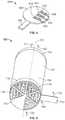
- FIG. 1Ashows an illustrative vapor transfer unit for humidity control
- FIG. 1Bshows a cross section view of the vapor transfer unit of FIG. 1A ;
- FIG. 2shows an illustrative vapor transfer unit for humidity control
- FIGS. 3 and 4show a vapor transfer unit having a valve for selectively obstructing tubes
- FIG. 5shows an illustrative valve for selectively obstructing the tubes of FIGS. 3 and 4 ;
- FIG. 6shows a vapor transfer unit having a rotating valve for selectively obstructing tubes
- FIGS. 7-11show bottom views of the vapor transfer unit of FIG. 6 having the rotating valve at various orientations
- FIGS. 12-16show bottom views of a vapor transfer unit having a rotating valve
- FIG. 17shows an exploded view of a vapor transfer unit having a rotatable housing
- FIG. 18shows an exploded view of another vapor transfer unit having a rotatable housing
- FIG. 19shows illustrative vapor transfer units having different output humidity levels
- FIG. 20shows a plot of relative humidity as a function of gas flow rate for the vapor transfer units of FIG. 19 ;
- FIG. 21shows a schematic representation of a humidification system, according to certain implementations.
- FIG. 22shows a front perspective view of a humidification system, according to certain implementations.
- FIG. 23shows a side perspective view of the humidification system of FIG. 22 , according to certain implementations.
- FIG. 24shows an illustrative process for controlling the humidity of a breathing gas by obstructing a subset of tubes, according to certain implementations
- FIG. 25shows an illustrative process for automatically controlling the humidity of a breathing gas, according to certain implementations.
- FIG. 26shows an illustrative process for controlling the humidity of a breathing gas, according to certain implementations.
- the systems, devices, and methods described hereincontrol the relative humidity of a breathing gas delivered from a breathing gas humidification system.
- the systems, devices and methodsimpede or prevent excessive humidification of a breathing gas at low gas flow rates while impeding or preventing a significant drop in humidity at high flow rates using a single vapor transfer unit.
- a fraction of gas flow through a vapor transfer unitbypasses humidification.
- the fraction of gas that bypasses humidificationvaries inversely with the flow rate. Thus, a larger fraction of the total flow is bypassed at lower flow rates to prevent excessive humidification which could cause condensation, while a smaller fraction of the gas is bypassed at high flow rates so that humidity at high flow rates remains acceptably high for patient comfort.
- the fraction of total flow that is admitted to the bypass passagemay be reduced automatically using a constriction in the bypass passage that is sized to admit a smaller fraction of the total flow as the flow rate increases.
- the bypass pathmay be manually controlled using a rotating or sliding valve.
- the total number of humidification elements exposed to the gas flowis varied to control the humidity level at high and low flow rates. In these implementations, more humidification elements are exposed to the flow at high flow rates, and fewer humidification elements are exposed to the flow at low flow rates.
- FIG. 1Ashows a vapor transfer unit 100 for humidity control, according to certain implementations.
- FIG. 1Bshows a cross section view 200 of the vapor transfer unit 100 .
- the vapor transfer unit 100includes a housing 102 having a longitudinal axis 132 , a gas inlet 104 , and a gas outlet 106 .
- the vapor transfer unit 100also includes a plurality of tubes 108 a - e disposed within the housing 102 .
- the tubes 108 a - eeach define a passage for the flow of gas from the gas inlet 104 to the gas outlet 106 .
- the tubes 108 a - emay be hollow fiber membranes that are permeable to water vapor, but are impermeable or somewhat impermeable to liquid water.
- Gas flowing in the inlet 104enters an upper chamber 134 and splits into the respective tubes 108 a - e , where the flow occurs in parallel.
- the gasthen combines in the bottom chamber 136 and then flows out of the gas outlet 106 .
- Between the tubes 108 a - eis a plurality of liquid regions 111 a - f in which liquid circulates.
- the tubes 108 a - eare porous so that the liquid circulating in the regions 111 a - f transfers vapor to the gas passing through the tubes 108 a - e as indicated by the arrows 130 .
- the gas 112is humidified as it travels along the humidification region 110 of the tubes 108 a - e .
- the tubes 108 a - epass through plugs 116 and 118 , and the outer surfaces of the tubes 108 a - e are held by the plugs 116 and 118 .
- the tubes 108 a - emay be held by an interference fit with the holes in the plugs 116 and 118 through which the tubes 108 a - e pass.
- the tubes 108 a - eare bonded to the plugs 116 and 118 .
- the plugs 116 and 118are substantially disk-shaped and concentric to the longitudinal axis 132 of the housing 102 .
- the plugs 116 and 118are held in the housing 102 by walls 123 and 125 .
- the plugsmay be held by an interference fit, bonded, or welded to the walls 123 and 125 , or connected to the walls 123 and 125 using any other suitable attachment, or combination thereof.
- the plugs 116 and 118support the tubes 108 while also enclosing the regions 111 a - f in which the liquid circulates.
- the vapor transfer unit 100also includes a bypass passage 109 that provides a passage from the gas inlet 104 to the gas outlet 106 .
- the bypass passageincludes a constriction 122 which provides resistance to the flow of gas 114 through the bypass passage 109 .
- the constriction 122is defined by a ring-shaped protrusion 121 that narrows the internal diameter of the bypass passage from an initial diameter 152 to a restricted diameter 150 .
- the restricted diameteris generally sized so that the flow resistance caused by the constriction 122 increases about linearly with velocity squared. In preferred implementations, the restricted diameter is about 0.75 mm-1.5 mm. In example embodiments, the restricted diameter is about 0.040 in (1.016 mm).
- the protrusion 121is located about midway between the gas inlet 104 and the gas outlet 106 and is oriented perpendicular to the longitudinal axis 132 of the housing 102 and separates an upstream portion 109 a of the bypass passage 109 from a downstream portion 109 b of the bypass passage 109 .
- the protrusion 121may be located closer to the gas inlet 104 or closer to the gas outlet 106 .
- the constriction 122is oriented oblique to the longitudinal axis 132 of the housing 102 .
- the protrusion 121can be formed by fabricating a wall (not shown) to separate the upstream portion 109 a of the bypass passage 109 from the downstream portion 109 b of the bypass passage 109 and then drilling a small hole in the wall.
- the bypass passage 109is separated from the regions 111 in which the liquid circulates by non-porous wall 123 . Since the wall 123 is non-porous, vapor is not transferred from the circulating liquid into the gas 114 passing through the bypass passage 109 .
- the vapor transfer unit 100is configured so that a first fraction 112 of the gas flow through the gas inlet 104 passes through the tubes 108 , and a second fraction 114 of the gas flow passes though the bypass passage 109 and exits as bypassed gas 124 .
- the fraction 112 passing through the tubes 108is humidified in the humidification region 110 , while the fraction 114 passing through the bypass passage 109 is not humidified.
- the first fraction 112exits the tubes 108 a - e as humidified gas 119 a - e , respectively, and recombines in the bottom chamber 136 to form the humidified gas 120 .
- the humidified gas 120 and the bypassed gas 124combine near the outlet 106 to form an output gas 126 .
- the resistance to gas flow through the bypass passage 109 caused by the constriction 122 in the bypass passage 109increases and in most cases more than the resistance to gas flow caused by the plurality of tubes 108 a - e .
- the resistance to flow through the tubes 108 a - eis mostly due to frictional drag against the walls of the tubes 108 a - e , while the losses due to entrance and exit effects are relatively minor.
- the resistance to flow through the constriction 122is generally due to entrance and exit effects (e.g., losses associated with compression of the gas entering the constriction 122 and expansion of the air exiting the constriction 122 ).
- the constriction 122allows the flow rate through the gas inlet 104 to be altered without significantly changing the relative humidity of the gas 126 exiting the gas outlet 106 .
- the gas flow 124 from the bypass passage 109combines with the gas flow 126 before the outlet 106 to lower the relative humidity of the output gas 126 exiting the gas outlet 106 to below saturation (100% relative humidity).
- the combination of humidified gas 120 with bypassed gas 124can thus lower the relative humidity of the output gas 126 to reduce the risk of unwanted condensation at low flow rates.
- the humidity of gas flow 120increases, but the fraction of bypassed gas 124 also increases. Therefore the increase in humidity at low flow rates is counteracted by an increase in the fraction 114 of gas that bypasses humidification.
- bypass passage 109helps impede or prevent condensation at low flow rates (e.g., flow rates through the gas inlet 104 of ⁇ 30 L/min, ⁇ 20 L/min, ⁇ 10 L/min, ⁇ 8 L/min, ⁇ 5 L/min, or any similar flow rate).
- the constriction 122reduces the risk of condensation at low flow rates, while not excessively reducing the humidification at high flow rates. Furthermore, the humidity control is achieved automatically and without the need for electronic sensors, actuators, feedback control systems, or valves. Instead, the internal dimensions of the bypass passage 109 and constriction 122 remain fixed during operation.
- FIG. 2shows a vapor transfer unit 300 for humidity control, according to certain implementations.
- the vapor transfer unit 300includes a housing 302 having a gas inlet 304 , a gas outlet 308 , a liquid inlet 312 , and a liquid outlet 316 .
- the housing 302encloses a plurality of tubes 320 a - h .
- the plurality of tubes 320 a - hincludes a first subset 322 of tubes 320 a - f and a second subset 324 of tubes 320 g - h .
- the tubes 320 a - f of the first subset 322are porous, while the tubes 320 g - h of the second subset 324 are non-porous.
- the tubes 320 a - hare supported at their ends 337 and 338 by plugs 330 and 336 , respectively.
- the plugs 330 and 336are disk-shaped and are held in place by the walls 350 and 351 of the housing 302 .
- the plugs 330 and 336also define the upper and lower boundaries of the liquid region 321 to enclose the liquid region 321 .
- the plugs 330 and 336separate the liquid region 321 from the upper chamber 332 and lower chamber 344 , through which gas passes.
- the liquid region 321is in fluid communication with the liquid inlet 314 and the liquid outlet 318 .
- gas 306passes through the gas inlet 304 into a top chamber 332 .
- the gasthen passes into the plurality of tubes 320 a - h , through tube inlets 326 and 328 .
- the gas that enters the tube inlets 326passes through the first subset 322 of porous tubes 320 a - f and is humidified in the humidification region 334 .
- the number of tubes in the first subset 322is sufficient to allow the gas passing therethrough to be humidified to nearly 100% relative humidity.
- Increasing the number of porous tubes 320 a - fcauses the humidified gas fraction 340 to have a higher relative humidity (e.g., closer to 100%), while decreasing the number of porous tubes 320 a - f causes the humidified gas fraction 340 to have a lower relative humidity.
- heated liquid 314enters the liquid inlet 314 and passes through the liquid region 321 .
- the liquidpasses over the outer surfaces of the tubes 320 a - h . Vapor is transferred from the liquid in region 321 to the gas passing through the porous tubes 320 a - f in the humidification region 334 as indicated by arrows 352 .
- the arrows 352only show the transfer of vapor at one location along the length of tubes 320 a - f , the vapor transfer occurs along the length of tubes 320 a - f in the humidification region 334 .
- the liquid 318exits the liquid outlet 316 .
- the gas that enters the tube inlets 328passes through the second subset 324 of non-porous tubes 320 g - h . Since the second subset 324 of tubes 320 g - h are nonporous, vapor cannot transfer from the liquid region 321 to the gas flowing through the second subset 324 of tubes 320 g - h .
- the second subset 324 of non-porous tubes 320 g - hmay be extruded plastic tubes.
- the second subset 324 of tubes 320 g - hare porous, but liquid is not supplied to the outer surfaces of the tubes 320 g - h to prevent humidification of the gas flowing therethrough. Although no vapor is transferred through the second subset 324 of tubes 320 g - h , The bypassed gas fraction 342 is still heated by the liquid circulating in the liquid region 321 .
- the humidified gas fraction 340 and the bypassed gas fraction 342exit the bottom region 338 of the first subset 322 and the second subset 324 , respectively, of tubes 320 a - h and mix in the bottom chamber 344 .
- the mixed output gas 310exits the vapor transfer unit 300 through gas outlet 308 .
- the humidity level of the output gas 310can be reduced to prevent humidity in the output gas 310 from condensing in the downstream flow path (not shown) when the output gas 310 cools.
- the fraction of bypassed gas 342remains about constant as the flow rate changes.
- the gas flowing through the first subset 322 of permeable tubes 320 a - fpasses more quickly through the humidification zone 334 and has less time to receive vapor from liquid in the liquid region 321 .
- the relative humidity of the output gas 310may fall if a sufficient quantity of tubes is not present.
- the increase in number of tubesincreases the size and cost of the VTC. Therefore, it may be preferable to have a valve for selectively obstructing the non-porous tubes 320 a - f at high flow rates to reduce the bypassed gas fraction 340 and prevent the output gas 310 from being excessively dry.
- FIGS. 3 and 4show a vapor transfer unit 400 having such a valve 410 for selectively obstructing tubes 404 and 406 , according to certain implementations.
- the vapor transfer unit 400is similar to the vapor transfer unit 300 in FIG. 2 and includes a housing 402 , a first subset of tubes 404 , and a second subset of tubes 406 .
- the first subset of tubes 404 and the second subset of tubes 406are functionally similar to the first subset 322 of tubes 320 a - f and the second subset 324 of tubes 320 g - h .
- the first subset of tubes 404 and the second subset of tubes 406are separated by a divider 408 .
- the housing 402has an upper end portion 402 a and a lower end portion 402 b .
- the valve 410is positioned against the lower end portion 402 b of the housing 402 .
- the valve 410may be held against the lower end portion 402 b by a fastener (not shown).
- the valve 410is allowed to slide along an axis 450 perpendicular to the longitudinal axis 452 of the housing 402 , while the valve 410 remains perpendicular to the longitudinal axis 452 of the housing 402 .
- the valve 410obstructs a cross section 424 of the lower end portion 402 b housing 402 and leaves exposed a cross section 426 of the lower end portion of the housing 402 .
- the valve 410includes calibrated notches 610 , 608 , and 606 , which allow a user to select a desired relative humidity of the output gas by aligning one of the notches 610 , 608 , or 606 with a bottom rim 456 of the housing 400 .
- the valve 410also includes a tab 454 which the user may push towards the housing 402 or pull away from the housing to increase or decrease, respectively, the cross section 424 that is obstructed.
- the valve 410allows gas 416 to flow through the tubes 406 , but obstructs gas flow through the tubes 404 .
- the tubes 406are porous, so the liquid 420 flowing through the housing 402 transfers vapor to the gas 416 through pores (not shown) in the tubes 406 as the liquid 420 flows from the lower end portion 402 b to the upper end portion 402 a of the housing 402 .
- the liquid 420humidifies the gas 416 that passes through the tubes 406 , and the gas 416 exits the tubes 406 as humidified gas 417 .
- the incoming gas 416is supplied by a gas inlet, and the humidified gas 417 exits through a gas outlet, but these gas ports are omitted from FIGS. 3 and 4 for the sake of clarity.
- the valve 410is set so that it allows the gas 416 to pass through the tubes 416 and to allow gas 418 to pass through the tubes 404 .
- the valve 410is set by manually sliding the valve 410 along the axis 450 to set the cross section 428 of the lower end portion 402 b of the housing 402 that is obstructed by the valve 410 .
- the valve 410 in FIG. 4has been displaced towards the housing 402 along the axis 450 . This displacement can be achieved by a pressing the tab 454 towards the housing 402 .
- the displacementis provided manually, but the valve is 410 can also be displaced automatically by an electronic control system.
- the gas 416is humidified as it passes through tubes 406 and exits the upper end portion 402 a of the housing 402 as humidified gas 417 .
- the tubes 404are non-porous, so the gas 418 is not humidified as it flows through the tubes 404 and exits the upper end portion 402 a of the housing 402 as bypassed gas 419 .
- the tubes 404are porous, but liquid is prevented from contacting the tubes 404 to prevent humidification of the gas 418 as it passes through the tubes 404 .
- the tubes 404can be covered with a potting compound to prevent liquid from contacting the tubes 404 .
- the humidified gas 417 and the bypassed gas 419combine to form an output gas (not shown), which is similar to output gas 310 in FIG. 2 .
- the relative humidity of the output gasis between the relative humidity of the humidified gas 417 and the relative humidity of the bypassed gas 419 .
- the relative humidity of the output gasdepends on the position of the valve 410 . If the valve 410 is set so that it obstructs flow through all of the tubes 404 , no bypassed gas 419 will mix with the humidified gas 417 . As a result, the relative humidity of the output gas would be about equal to the relative humidity of the humidified gas 417 .
- the relative humidity of the humidified gas 417is high (e.g., >70%, >80%, >90%, >95%, >99%, or nearly 100%). If the valve 410 is set so that it allows flow through more of the tubes 404 , a greater fraction of bypassed gas 419 is included in the output gas and the relative humidity level of the output gas drops. Therefore, the tubes 404 act as a bypass passage, similar to the bypass passage 109 of the vapor transfer unit 100 . By allowing the tubes 404 to be open at low flow rates and obstructed by the valve 410 at high flow rates, condensation can be reduced at low flow rates, while maintaining high humidity and preventing a significant drop in humidity at high flow rates. A significant drop in humidity may be a reduction in the relative humidity of >40%, >30%, >20%, >15%, >10%, >5%, or a similar reduction in relative humidity.
- the tubes 404are porous like the tubes 406 .
- the gas 419is humidified when passing through tubes 404 similar to how gas 417 is humidified when passing through tubes 406 .
- the humidity level of the output gasis controlled by varying the total number of tubes 404 and 406 that are obstructed by the valve 410 . Increasing the total number of tubes 404 and 406 obstructed by the valve 410 decreases the total number of tubes 404 and 406 exposed to the flow of gas 416 and 418 . This decreases the surface area available for the transfer of vapor to the gas and thus decreases the relative humidity of the output gas.
- both the tubes 404 and 406are exposed to gas flow when the gas flow rates are above a threshold, and the tubes 404 are obstructed by the valve 410 at rates below the threshold.
- the thresholdmay be about 8 L/min, 20 L/min, 30 L/min, 40 L/min or any other suitable flow rate.
- the change in the number of tubes 404 and 406 exposed to gas flowcan be done by sliding the valve 410 along the axis 450 . The sliding of the valve 410 can be done manually by a user or automatically by an electronic control system.
- the effective area for humidificationis about 100 square centimeters
- the effective area for humidificationis about 50 square centimeters. Since the humidity of the output gas tends to drop as the rate of flow of gas 416 and 418 through the housing 402 increases, allowing more tubes to be exposed to the flow of gas 416 and 418 at higher flow rates can counteract this drop in humidity. In contrast, the relative humidity of the output gas tends to rise as the rate of gas flow through the housing 402 decreases.
- reducing the number of tubes 404 and 406 exposed to the gas flow using the valve 410can reduce the humidity of the output gas which can prevent excess humidity from causing condensation.
- a single vapor transfer unit 400can be used to provide adequate humidity at both low and high flow rates using the valve 410 .
- the humidity of the output gas of the vapor transfer unit 400is controlled by controlling the flow of gas 416 and 418 through the tubes 404 and 406
- the humidity of the output gasis controlled by changing the number of tubes 404 and 406 exposed to the flow of liquid 420 .
- the number of tubes 404 and 406 that are exposed to the flow of the liquid 420can be altered using a valve (not shown). The valve allows the user to select whether the liquid 420 entering the liquid inlet 414 is admitted on both sides of the divider 408 .
- the divider 408allows the flow of the liquid 420 around the tubes 406 to be isolated from the flow of the liquid 420 around the tubes 404 .
- the number and type of exposed tubescan be varied by use of the valve.
- the valveIn a first position, the valve can allow the liquid 420 to flow around the tubes 406 . In a second position, the valve can allow liquid 420 to flow around the tubes 406 and 408 .
- the valveIn only the tubes 406 are exposed to the flow of liquid 420 and both the tubes 404 and 406 are exposed to gas flow, only half of the output gas is humidified.
- the tubes 404 and 406are both exposed to the flow of liquid 420 , all of the output gas is humidified.
- the humidity of the output gascan be controlled.
- FIG. 5shows a perspective view of the valve 410 of the vapor transfer unit 400 of FIGS. 3 and 4 .
- the valve 410includes a valve body 602 and a tab 604 .
- the valve bodyincludes notches 606 , 608 , and 610 and corresponding labels 612 , 614 , and 616 , respectively.
- the labels 612 , 614 , and 616indicate the relative humidity of the output gas of the vapor transfer unit 400 that is achieved when the valve 410 is set such that the notches 606 , 608 , or 610 are aligned with the bottom rim 456 of the housing 402 of vapor transfer unit 400 . Aligning the notches 606 , 608 , and 610 with the bottom rim 456 of the housing 402 leaves open a cross section of the lower end portion 402 b of the housing 402 , such as cross section 430 in FIG. 4 .
- the tab 604is manipulated by a user to adjust the area of the valve body 602 that is used to obstruct gas flow.
- a usermay select a desired humidity level and move the valve 410 to the position corresponding thereto using the labels 612 , 614 , and 616 .
- the notch 606would be aligned with the bottom rim 456 of the vapor transfer unit 400 as shown in of FIG. 4 , leaving exposed a cross section 430 of the lower end portion 402 b of the housing 402 .
- the area 428 obstructed by the valve 410is increased (to decrease the humidity) by pressing the tab 604 until the notch with the desired humidity level aligns with the bottom rime 456 of the housing 402 .
- the area 428 obstructed by the valve 410can similarly be decreased (to increase the humidity) by pulling the tab 604 to displace the valve 410 away from the housing 402 .
- the valve 410allows precise manual control of the humidity levels of the output gas.
- the valvemay be marked with any suitable number of notches to indicate any suitable relative humidity level, including relative humidity levels over 75%.
- the relative humidity levels indicated on the valve 410can include 80%, 90%, 95%, 99%, and nearly 100%.
- the valve 410may be automatically controlled.
- the valve 410can be actuated by an electromechanical control system.
- the electromechanical control systemcan use a humidity sensor to monitor the humidity of the output gas and adjust the valve 410 accordingly.
- FIG. 6shows a vapor transfer unit 700 having a rotating valve 708 for selectively obstructing tubes 716 and 718 , according to certain implementations.
- the vapor transfer unit 700includes the rotating valve 708 and a housing 702 having a longitudinal axis 701 , a first end portion 704 , and a second end portion 706 opposite the first end portion 704 .
- Disposed within the housing 702are a first group of porous tubes 716 and a second group of non-porous tubes 718 , each tube extending longitudinally within the housing 702 along the longitudinal axis 701 .
- the tubes 718are porous, but liquid is prevented from contacting the tubes 718 to prevent humidification of gas passing therethrough.
- the rotating valve 708includes a tab 712 , a rim 710 , and a cover 714 .
- the cover 714prevents gas flow 720 from passing through the subset of tubes behind the cover 714 (not shown).
- the rim 710 of the rotating valve 708is coupled to the second end portion 706 of the housing 702 .
- the coupling between the rotating valve 708 and the second end portion 706 of the housing 702allows the rotating valve 708 to rotate relative to the housing 702 about the longitudinal axis 722 , as indicated by the arrow 713 .
- the tab 712is used to rotate the rotating valve 708 and thereby change the subset of tubes obstructed by the cover 714 .
- the tab 712can be rotated manually or automatically by an electronic control system.
- gas 720flows through the vapor transfer unit 700 from the second end portion 706 towards the first end portion 704 along the longitudinal axis 722 .
- the gas 720flows through the interior of the tubes 716 and 718 that are not obstructed by the cover 714 .
- the gas that flows through the porous tubes 716exits the vapor transfer unit 700 as humidified gas 721 , while the gas that flows through the non-porous tubes exits the vapor transfer unit as bypassed gas 722 .
- Rotating the rotating valve 708 about the longitudinal axis 701changes the subset of tubes that are obstructed (not shown) and can change the ratio of unobstructed porous tubes 716 to unobstructed non-porous tubes 718 .
- the ratio of unobstructed porous tubes 716 to unobstructed non-porous tubes 718determines the amount of bypassed gas 722 that is mixed with humidified gas 721 to form the output gas (not shown).
- the valve 708by rotating the valve 708 , the relative humidity of the output gas can be controlled.
- FIGS. 7-11show bottom views of the vapor transfer unit 700 of FIG. 6 having the rotating valve 708 positioned in various orientations.
- the rotating valveis positioned so that the cover 714 completely obstructs flow through the non-porous tubes 718 (not shown).
- the output gascan have a relative humidity of about 100%.
- the valve 708has been rotated by an angle 902 relative to the position in FIG. 7 .
- gas flowis allowed through some of the non-porous tubes 718 .
- a fraction of the gas passing through the vapor transfer unit 700is not humidified and exits as bypassed gas.
- FIG. 7the rotating valve is positioned so that the cover 714 completely obstructs flow through the non-porous tubes 718 (not shown).
- the output gascan have a relative humidity of about 100%.
- the valve 708has been rotated by an angle 902 relative to the position in FIG. 7 .
- gas flowis allowed through some of the non-porous tubes 718 .
- the ratio of unobstructed porous tubes 716 to unobstructed non-porous tubes 718is about 19. In other words, about 95% of the gas passing through the vapor transfer unit 700 is humidified while 5% is bypassed. The mixture of the small percentage of bypassed gas slightly lowers the relative humidity of the gas output in FIG. 8 relative to FIG. 7 .
- the valve 708has been rotated relative to FIG. 8 to expose more non-porous tubes 718 .
- the ratio of unobstructed porous tubes 716 to unobstructed non-porous tubes 718is about 9. Therefore, about 90% of the gas passing through the vapor transfer unit 700 is humidified while 10% is passed as bypassed gas.
- FIG. 10shows the valve 708 in the position in which the gas output has the lowest humidity possible with the particular valve configuration depicted.
- the ratio of unobstructed porous tubes 716 to unobstructed non-porous tubes 718is 5 and the output gas is about 80% humidified gas and 20% bypassed gas.
- FIGS. 7-11show that, various output relative humidity levels can be achieved by rotating the valve 708 relative to the vapor transfer unit 700 .
- FIGS. 12-16show bottom views of a vapor transfer unit 1300 having a rotating valve 708 , according to certain implementations.
- the vapor transfer unit 1300includes porous tubes 1316 . Unlike the vapor transfer unit 700 depicted in FIGS. 6-11 , the vapor transfer unit 1300 does not include non-porous tubes. Instead, the vapor transfer unit 1300 includes a blocked section 1318 which does not admit the flow of gas.
- the valve 708is positioned to allow gas flow through all or nearly all of the tubes 1316 . Therefore, the position of the valve 708 in FIG. 12 corresponds to the maximum humidification possible using the vapor transfer unit 1300 having the particular design depicted in FIGS. 12-16 . In some implementations, when the valve 708 is in the position depicted in FIG. 12 , the effective area available for vapor transfer is 100 square centimeters.
- the valve 708has been rotated to expose some of the blocked section 1308 and to obstruct a portion of the porous tubes 1316 .
- the total number of tubes 1316 exposed to the flow of gas through the vapor transfer unit 1300is reduced in FIG. 13 relative to FIG. 12 .
- about 95% of the tubes 1316 disposed within the vapor transfer unit 1300are exposed to gas flow.
- the valve 708is positioned so that 90% of the tubes 1316 are exposed to the flow of gas.
- the valve 708is positioned so that 85% of the tubes 1316 are exposed to the flow of gas.
- 80% of the tubes 1316are exposed to the flow of gas in FIG. 16 .
- valve 708By rotating the valve 708 , varying amounts of porous tubes 1316 can be exposed to the flow of gas. At low flow rates, gas passes more slowly through the tubes 1316 and has more time for humidification to occur. If the flow rates are below a certain rate (e.g., 30 L/min, 20 L/min, 8 L/min, or another similar flow rate), the output gas may become excessively humid and cause condensation downstream in the circuit when the output gas cools slightly. To counteract this effect, the valve 708 can be rotated to reduce the number of tubes 1316 exposed to the flow of gas. As a result, the output gas can be prevented from reaching excessive levels of humidity.
- a certain ratee.g. 30 L/min, 20 L/min, 8 L/min, or another similar flow rate
- the gaspasses through the porous tubes 1316 more rapidly, allowing less time for humidification.
- the output gasmay have lower humidity levels at higher flow rates (e.g., >8 L/min, >20 L/min, >30 L/min, or another similar flow rate).
- Delivering breathing gas having inadequate humiditye.g., humidity of ⁇ 99%, ⁇ 95%, ⁇ 90%, ⁇ 80%, or at some similar humidity level
- the valve 708can be positioned to allow gas flow through a high percentage of or all of the porous tubes 1316 .
- the humidity of the output gascan be controlled to prevent condensation at low flow rates and to prevent inadequate humidification at high flow rates.
- FIG. 17shows an exploded view of a vapor transfer unit 1900 having a rotatable housing 1908 , according to certain implementations.
- the vapor transfer unit 1900is similar to the vapor transfer unit 700 shown in FIG. 6 .
- the vapor transfer unit 1900includes a housing 1908 having a longitudinal axis 1950 , an upper end 1908 a , a lower end 1908 b , a low flow label 1912 , a high flow label 1914 , and an end cap 1902 .
- the end cap 1902mates with the lower end 1908 b of the housing 1908 such that the housing 1908 can rotate relative to the end cap 1902 .
- a plurality of tubes 1920 and 1930Disposed within the housing 1908 are a plurality of tubes 1920 and 1930 that extend longitudinally along the longitudinal axis 1950 of the housing 1908 .
- the tubes 1920are non-porous and the tubes 1930 are porous.
- the non-porous tubes 1920are scattered among the porous tubes 1930 .
- the ratio of porous tubes to non-porous tubesis 1:4.
- the end cap 1902includes a cover 1904 , for obstructing the portion of the tubes 1920 and 1930 located behind the cover 1904 and an opening 1906 for admitting gas flow 1903 through the remainder of the tubes 1920 and 1930 .
- the end cap 1902functions similarly to the valve 708 in FIG. 6 , but the end cap 1902 remains stationary relative to the humidification system (not shown) while the housing 1908 and tubes 1920 and 1930 rotate. Since the non-porous tubes 1920 are scattered among the porous tubes 1930 , rotating the housing 1908 and the tubes 1920 and 1930 relative to the end cap 1902 does not significantly change the ratio of porous tubes 1930 to non-porous tubes 1920 aligned with the opening 1906 of the end cap 1902 .
- incoming gas 1901flows through the tubes 1920 and 1930 that are aligned with the opening 1906 in the end cap 1902 .
- liquid(not shown) is circulated within the housing 1908 between the tubes 1920 and 1930 .
- the liquidtransfers vapor to the gas 1901 as it flows through the porous tubes 1920 that are aligned with the opening 1906 in the end cap 1902 .
- rotating the housing 1908 and the tubes 1920 and 1930 relative to the end cap 1902does not significantly change the ratio of porous tubes 1930 to non-porous tubes 1920 exposed to the flow of incoming gas 1903 .
- the amount of vapor transferred to the gas 1901 and the relative humidity of the output gas 1903is not significantly affected by rotating the housing 1908 and tubes 1920 and 1930 relative to the end cap 1902 .
- the labels 1912 and 1914are also rotated.
- An optical sensor 1962detects the label that is in its line of sight 1960 .
- rotating the housing 1908changes which label is exposed to the optical sensor 1962 .
- the optical sensorconfigures the flow settings for the overall humidification system (not shown) based on the label that is detected.
- the optical sensorcan be a camera, a bar code scanner, an infrared sensor, or any other suitable sensor.
- the high flow label 1912is aligned with the line of sight of 1960 of the optical sensor 1962 .
- the optical sensor 1962detects the presence of a high flow vapor transfer unit and configures the humidification system for operation at high flow rates.
- the humidification systemmay be permitted to operate at higher flow rates than when a low flow vapor transfer unit is detected.
- the labels 1912 and 1914are rotated to align the low flow label 1914 with the line of sight 1960 of the optical sensor 1962 , the optical sensor 1962 detects the presence of a low flow vapor transfer unit and configures the humidification system for operation at low flow rates.
- the high flow therapy systemcan be enabled to use a single vapor transfer unit 1900 at either the high flow or low flow settings. This enables the vapor transfer unit 1900 to be retrofitted for use with existing high flow therapy systems that are configured to operate with separate vapor transfer units for high and low flow.
- FIG. 18shows an exploded view of a vapor transfer unit 2000 with a rotatable housing 2008 , according to certain implementations.
- the vapor transfer unit 2000is similar to the vapor transfer unit 1900 shown in FIG. 17 and the vapor transfer unit 700 shown in FIG. 6 .
- the vapor transfer unit 2000includes a housing 2008 having a longitudinal axis 2050 , an upper end 2008 a , a lower end 2008 b , a low flow label 2012 , a high flow label 2014 , and an end cap 2002 .
- the end cap 2002mates with the lower end 2008 b of the housing 2008 such that the housing 2008 can rotate relative to the end cap 2002 .
- a plurality of tubes 2020 and 2030Disposed within the housing 2008 are a plurality of tubes 2020 and 2030 that extend longitudinally along the longitudinal axis 2050 of the housing 1908 .
- the tubes 2030are porous and the tubes 2020 are blocked to prevent gas flow.
- the blocked tubes 2020are grouped together. In some implementations, the ratio of porous tubes to blocked tubes is 1:3.
- the end cap 1902includes a cover 1904 , for obstructing the portion of the tubes 2030 located behind the cover 1904 and an opening 1906 for admitting gas flow 2003 through the remainder of the tubes 2030 .
- the tubes 2020are blocked by design, so they do not require the end cap to block flow through them.
- the end cap 1902functions similarly to the end cap of FIG. 17 .
- the end cap 1902remains stationary relative to the humidification system (not shown) while the housing 2008 and tubes 2020 and 2030 rotate.
- the blocked tubes 2020are grouped in the low flow side 2011 of the housing 2008 labeled with the high flow label 2012 .
- incoming gas 2001flows through the tubes 2030 that are aligned with the opening 1906 in the end cap 1902 .
- liquid(not shown) is circulated within the housing 1908 between the tubes 2020 and 2030 .
- the liquidtransfers vapor to the gas 2001 as it flows through the porous tubes 2020 that are aligned with the opening 1906 in the end cap 1902 .
- the blocked tubes 2020are grouped on the low flow side 2011 of the housing 2008 , when the low flow side 2011 of the housing 2008 is aligned with the opening 1906 in the end cap 1902 , fewer porous tubes 1920 are exposed to the gas flow 2001 .
- the number of porous tubes 2030 exposed to the flow 2001 at high flow ratesis twice the number of porous tubes exposed to the flow 2001 at low flow rates.
- the surface area available for vapor transfermay be 100 square centimeters at high flow rates and 50 square centimeters at low flow rates. While the tubes 2020 are blocked in vapor transfer unit 2000 , in some implementations, the tubes 2020 are non-porous and admit air flow. Thus, the amount of vapor transferred to the gas 2001 and the relative humidity of the output gas 2003 is significantly lower when the low flow side 2011 of the housing is aligned with the opening 1906 in the end cap 1902 .
- An optical sensor 1962detects the label that is in its line of sight 1960 and configures the flow settings for the overall humidification system (not shown) based on the label that is detected.
- the optical sensorcan be a camera, a bar code scanner, an infrared sensor, or any other suitable sensor.
- the high flow label 2012is aligned with the line of sight of 1960 of the optical sensor 1962 .
- the optical sensor 1962detects the presence of a high flow vapor transfer unit and configures the humidification system for operation at high flow rates.
- the housing 2008when the housing 2008 is so positioned, the tubes on the high flow side 2007 of the housing are exposed to the flow of gas 2001 .
- the humidificationmay be permitted to operate at higher flow rates than when a low flow vapor transfer unit is detected.
- the low flow label 2008is positioned in the line of sight 1960 of the optical sensor.
- the optical sensordetects the presence of a low flow vapor transfer unit and configures the humidification system for operation at low flow rates.
- the configuration of the humidification systemmay include a setting for a maximum flow rate for flowing the gas 2001 through the vapor transfer unit 2020 to prevent inadequate humidification of the output gas 2003 .
- the labels 2012 and 2014allow the humidification system to adjust its settings based on whether the positioning of tubes 2020 and 2030 correspond to the high flow or low flow configurations. This enables the vapor transfer unit 2000 to be operated at both high and low flow rates.
- the optical sensorcan detect intermediate positions between high and low flow rate configurations and can adjust the settings of the humidification system accordingly.
- FIG. 19shows illustrative bypass units 2100 , 2120 , 2140 , and 2160 having different output humidity levels.
- Bypass unit 2100includes a first vapor transfer unit 2102 and a second vapor transfer unit 2104 .
- the first vapor transfer unitincludes a gas inlet 2106 , a gas outlet 2108 , a liquid inlet 2114 , and a liquid outlet 2116 .
- the second vapor transfer unitincludes a gas inlet 2110 , a gas outlet 2112 , a liquid inlet 2118 , and a liquid outlet 2119 .
- the gas inlet 2110 of the second vapor transfer unitis connected to an upstream end 2101 of the first vapor transfer unit 2102
- the gas outlet 2112 of the second vapor transfer unit 2104is connected to a downstream end 2103 of the first vapor transfer unit 2102 .
- the gas inlet 2106 of the first vapor transfer unit 2102is coupled to a gas source and output gas exits the gas outlet 2108 .
- Gas flowing into the gas inlet 2106flows through both vapor transfer units 2102 and 2104 in parallel.
- liquidis passed into the liquid inlet 2114 and out of the liquid outlet 2116 of the vapor transfer unit 2102 , but no liquid is passed through the liquid inlet 2118 of the second vapor transfer unit 2104 .
- the gas flowing through the first vapor transfer device 2102is humidified while the gas passing through the second vapor transfer device 2104 is not humidified.
- the humidified gas from the first vapor transfer unit 2102 and the bypassed gas from the second vapor transfer unit 2104mix in the downstream end 2103 of the first vapor transfer unit 2102 to form the output gas.
- the ratio of gas passed through the first vapor transfer unit 2102 to the gas passed through the second vapor transfer unit 2104determines the relative humidity of the output gas.
- the vapor transfer unit 2102has the same number of tubes (not shown) disposed within its housing and the same internal flow resistance as does the vapor transfer unit 2104 . Therefore, the amount of gas flow through the first vapor transfer unit 2102 is about equal to the amount of gas flow through the second vapor transfer unit 2104 .
- bypass unit 2120 and 2140have configurations similar to the bypass unit 2100 , but each bypass unit 2120 and 2140 includes a different combination of vapor transfer units.
- Bypass unit 2120includes a high flow vapor transfer unit 2122 and a low flow vapor transfer unit 2124 .
- the low flow vapor transfer unit 2124has half the number of tubes (not shown) disposed within its housing as does the high flow vapor transfer unit 2122 . Therefore, the low flow vapor transfer unit 2124 has about twice the flow resistance of the high flow vapor transfer unit 2122 .
- the bypass unit 2120causes two thirds (about 67%) of its gas input to be humidified and one third (about 33%) of its gas input to bypass humidification.
- bypass unit 2140includes a high flow vapor transfer unit 2142 and a low flow vapor transfer unit 2144 .
- the low flow vapor transfer unit 2144has a quarter the number of tubes (not shown) disposed within its housing as does the high flow vapor transfer unit 2142 .
- the low flow vapor transfer unit 2144has about four times the flow resistance of the high flow vapor transfer unit 2142 .
- 80% of the gas flow into bypass unit 2140is humidified, while 20% of the gas flow bypasses humidification.
- bypass units 2100 , 2120 , and 2140can achieve various relative humidity output levels below 100%.
- FIG. 19also shows a bypass unit 2160 , including a single vapor transfer unit 2162 and a bypass tube 2164 .
- the vapor transfer unit 2162includes a gas inlet 2166 , a gas outlet 2168 , a liquid inlet 2174 , and a liquid outlet 2176 .
- a first fraction (not shown) of the gas entering the gas inlet 2166is passed through the vapor transfer unit 2162 and is humidified by liquid that enters the liquid inlet 2174 .
- a second fraction (not shown) of the gas entering the gas inlet 2166is passed through the bypass tube 2164 and bypasses humidification.
- the humidified gasmixes with the bypassed gas in the downstream end 2163 of the vapor transfer unit 2160 and exits the gas outlet 2168 as output gas.
- the bypass tube 2164includes a small orifice (not shown) having a diameter of 0.040 in (about 1 mm).
- the orificecauses the fraction of the gas flow passed through the bypass tube 2164 to decrease as the flow rate increases. As a result, a greater fraction of gas is passed through the bypass tube 2164 at low flow rates and a smaller fraction of gas is passed through the bypass tube 2164 at low flow rates. This change in the fraction of bypassed gas in response to flow rate helps to prevent excessive humidification at low flow rates to prevent or reduce condensation, while not significantly decreasing humidity at high flow rates.
- the bypass units 2100 , 2120 , 2140 , and 2160were constructed and tested by Applicant.
- a prior art vapor transfer unit(a High Flow Vapor Transfer Cartridge supplied by Vapotherm, Inc., Morris, N.H.), was also tested for comparison. The results of the tests are shown in FIG. 20 .
- pairs of vapor transfer unitswere connected to allow flow communication between the two gas inlet ports and between the two gas outlet ports of the connected vapor transfer units. Only one of the two vapor transfer units was supplied with a flow of water while the other vapor transfer unit had its liquid inlet and liquid outlet sealed.
- Table 1indicates the configurations of bypass units 2100 , 2120 , and 2140 .
- the first columnindicates the bypass unit by reference numeral.
- the second columnindicates the percentage of gas that is humidified and the percentage of gas that bypasses humidification.
- the humidification vapor transfer unit columnidentifies the vapor transfer unit that was connected to a water source for humidification.
- the bypassing vapor transfer unit columnindicates the type of vapor transfer unit that was used to bypass the humidification vapor transfer unit.
- the high flow vapor transfer unitshad twice the number of tubes as the low flow vapor transfer units. Additionally, the low flow vapor transfer unit 2144 used to fabricate the bypass unit 2140 had 50% of its tubes blocked.
- the low flow vapor transfer unit 2144 used in the bypass unit 2140had a quarter the number of available tubes that the high flow vapor transfer units 2102 , 2122 , and 2142 had.
- the bypass unit 2160was fabricated using a high flow rate vapor transfer unit 2162 and a bypass tube 2164 having a 0.25 in (6.35 mm) outer diameter.
- the tubewas bonded to the outside of the vapor transfer unit 2162 .
- the orifice(not shown) was formed by drilling a 0.040 in (1.02 mm) diameter hole into the vapor transfer unit 2162 at the point where the vapor transfer unit 2162 connects to the bypass tube 2160 .
- the humidity data plotted in FIG. 20was gathered using capacitive humidity sensors (Sensirion). For each bypass unit and for the prior art vapor transfer unit, humidity was measured at a distal end of a delivery tube that was connected to the available gas outlet. The gas flow rate was initially set to 40 L/min, and the vapor transfer units were allowed to reach steady state. After a steady state was achieved, data logging was initiated, and the flow rate was reduced by 1 L/min increments every 30 seconds.
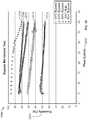
- FIG. 20shows a plot of relative humidity as a function of gas flow rate for the bypass units 2100 , 2120 , 2140 , and 2160 of FIG. 19 and for a prior art vapor transfer unit.
- the x-axis 2202 of the plotrepresents the total gas flow rate measured in L/min.
- the y-axis 2204represents the percent relative humidity of the output gas.
- the humidity curves 2206 , 2208 , 2210 , 2212 , and 2214correspond to a prior art vapor transfer unit, bypass unit 2160 , bypass unit 2140 , bypass unit 2120 , and bypass unit 2100 , respectively.
- the humidity curve 2206 of the prior art vapor transfer unitshows that the relative humidity is significantly above 90% for flow rates below 30 L/min, and drops relatively steeply for flow rates in the range of 30-40 L/min.
- the high relative humidity of the prior art vapor transfer unit at the low flow ratescauses condensation to occur when the output gas cools slightly.
- the humidity curves 2210 , 2212 , and 2214demonstrate more consistent humidity levels than the prior art system. At low flow rates, the humidity curves 2210 , 2212 , and 2214 each exhibit a relative humidity about equal to the percent of the gas that passes through the humidification vapor transfer unit of the corresponding bypass unit.
- the humidity curve 2214initially shows a relative humidity of about 50%, and the bypass unit 2100 , to which the curve corresponds, passes 50% of its gas flow through the humidification vapor transfer unit (vapor transfer unit 2102 in FIG. 19 ).
- the humidity curve 2212shows a relative humidity of about 70% at low flow rates, and the bypass unit 2120 , to which the curve corresponds, passes about 67% of its gas flow through the humidification vapor transfer unit.
- the relative humidity curves 2206 , 2208 , 2210 , 2212 , and 2214are all downward sloping because as flow rates increase, the gas passes more quickly through the humidification vapor transfer unit and has less time to receive humidity. However, the slopes of the humidity curves 2208 , 2210 , 2212 , and 2214 are shallower than the slope of the humidity curve 2206 . Thus, the bypass units 2100 , 2120 , 2140 , and 2160 achieved more consistent humidification than the prior art system.
- the humidity curve 2208which corresponds to the bypass unit 2160 having the orifice design, shows the shallowest slope and, therefore, the most consistent humidity level.
- the curve 2208shows a relative humidity of about 85% relative humidity or lower at low flow rates (e.g., ⁇ 15 L/min) and a relative humidity of between 75% and 80% at flow rates above 35 L/min. At the highest flow rates measured, about 40 L/min, the humidity curve 2208 shows a relative humidity within about 5% of the relative humidity of the humidity curve 2206 of the prior art system.
- the bypass unit 2160 having the orifice designexhibits a relative humidity at low flow rates low enough to prevent excessive humidification and condensation, while exhibiting humidity levels comparable to the prior art system at high flow rates.
- the bypass unit 2160demonstrates that having a bypass passage with an orifice design can achieve acceptable performance at both high and low flow rates
- Humidification system 2300delivers heated and humidified breathing gas 80 to a patient and includes a base unit 10 and a fluid pathway module 20 .
- the illustrated base unit 10includes controls for operating the humidification system 2300 and is configured to receive breathing gas 50 a and 50 b , such as medical air and oxygen, respectively. Alternatively, the controls may be remote from the base unit 10 .
- other gasessuch as, for example, helium, nitric oxide (INO), or any other suitable gas or combination of gasses, may be used.
- gases 50 a and 50 bmay be blended by a gas blending device 84 , to form blended gas 60 , which is delivered to the fluid pathway module 20 . While two different gases may be used with system 2300 , those skilled in the art will recognize that the system 2300 may be used with only one gas, such as, for example air or pure oxygen, in which case the gas blending device 84 may be omitted.
- the fluid pathway module 20is releasably mounted to the base unit 10 and is configured to receive gas 60 from the base unit 10 and liquid 70 from an external water source.
- liquid 70 received by the fluid pathway module 20is contained in a reservoir 32 to minimize potential contamination of the base unit 10 and to prime a pump used to circulate liquid 70 .
- Liquid 70 contained in the reservoir 32may be heated by a heat conduction 62 from the base unit 10 .
- a vapor transfer unit 99is releasably mounted to the fluid pathway module 20 and combines liquid 70 from reservoir 32 with blended gas 60 to supply heated and humidified breathing gas 80 to a patient.
- the vapor transfer unit 99includes an apparatus for humidity control, and may be similar to the vapor transfer units 100 , 300 , 400 , 700 , or 1300 or bypass units 2100 , 2120 , 2140 , or 2160 described above. In implementations in which the humidity level is controlled by making adjustments to the vapor transfer unit 99 (e.g., vapor transfer unit 700 ), access to the vapor transfer unit 99 is permitted without requiring removal of the vapor transfer unit 99 from the base unit 10 .
- the vapor transfer unit 99allows the humidity level of the humidified breathing gas 80 to be kept in an acceptable range throughout a wide range of gas flow rates (e.g., 5 L/min to 40 L/min).
- the humidity level of the humidified breathing gas 80is kept below levels that would cause condensation. Additionally, the humidity level of the humidified breathing gas 80 remains high enough at high flow rates to provide adequate levels of humidity for patient comfort.
- the vapor transfer unit 99 for controlling humidityinto the system 2300 , the humidity of the humidified breathing gas 80 can be controlled.
- FIG. 22shows a front perspective view of the humidification system 2300
- FIG. 23shows a side perspective view of the humidification system 2300 , according to certain implementations.
- the humidification system 2300includes the base unit 10 , which contains the controls that operate humidification system 2300 and is configured to operate without liquid flowing internally through the base unit 10 or being exchanged with the fluid pathway module 20 .
- the base unit 10is completely dry so that potential damage to electronics that control humidification system 2300 and bacterial contamination of the base unit 10 is minimized.
- the base unit 10is mountable to a stand 90 , such as an IV pole, via mounting mechanism 95 , shown in FIG. 3 .
- a rear panel 2 of the base unit 10includes a bracket 95 b and a knob 95 a that manipulates the bracket 95 b to releasably secure the base unit 10 to the stand 90 .
- the knob 95 aWhen the knob 95 a is rotated, for example, the bracket 95 b may be tightened or loosened on the stand 90 , thereby securing or loosening the humidification system 2300 with respect to the stand 90 .
- the rear of the base unit 10further includes gas inlet ports with filters, such as port 1 a , that are configured to connect to gas supply lines (not shown).
- the gas supply linessupply gas (such as medical air and oxygen) from a portable tank, compressor, or wall outlet into the base unit 10 .
- gas supplied to the base unit 10may be filtered and blended to provide a contaminant-free gas mixture.
- a gas blending device(not shown in FIGS. 22 and 23 ), for example, may be installed within the base unit 10 to blend gas being supplied into the base unit 10 .
- the side of the base unit 10includes a door 3 that may be slid open or closed to expose or cover a component receiving portion 19 of the base unit 10 .
- the door 3may be slid completely closed to cover the component receiving portion 19 from view.
- door 3is slid open to expose component receiving portion 19 of the base unit 10 .
- the fluid pathway module 20can be releasably mounted or removed from the component receiving portion 19 , e.g., using a handle 21 .
- a guide 44extends from the side of component receiving portion 19 to align and secure fluid pathway module 20 to base unit 10 .
- FIG. 23shows the fluid pathway module 20 partially installed on base unit 10 .
- fluid pathway module 20When fluid pathway module 20 is mounted to the base unit 10 , the fluid pathway module 20 is positioned to receive gas from the base unit 10 .
- a gas outlet (not shown) of base unit 10engages a gas inlet (not shown) of fluid pathway module 20 to form an airtight channel through which gas, received through the inlet port 1 a , may be transferred to fluid pathway module 20 .
- the fluid pathway module 20is also configured to receive liquid from a liquid supply line 75 via liquid inlet 24 . Liquid may be supplied to the fluid pathway module 20 , for example, via a sterile water bag (not shown) that is suspended above the humidification system 2300 .
- the sterile water bagmay be punctured by a tube spike (not shown), with water being gravity fed from the water bag into the fluid pathway module 20 via a liquid supply line 75 .
- An exemplary tube spikeis disclosed in U.S. Pat. No. 7,654,507 owned by the Assignee of the present application, which is incorporated herein in its entirety by reference.
- Liquidis stored within the reservoir 32 (shown schematically in FIG. 21 ) in fluid pathway module 20 that is provided to receive liquid from the water bag as well as recirculated liquid.
- the liquid in fluid pathway module 20does not flow through base unit 10 .
- Liquid contained in the fluid pathway module 20is vaporized in the vapor transfer unit 99 and combined with gas from the base unit 10 to generate the humidified breathing gas.
- a delivery tube 85is releasably coupled to a breathing gas outlet 25 of the fluid pathway module 20 to deliver humidified breathing gas to the patient.
- the humidification system 2300has a front panel 4 that includes a display panel 5 , such as a liquid crystal display (LCD) or a light emitting diode (LED) display that provides visual indication of user settings and status conditions of the humidification system 2300 .
- the user settingsmay include user adjustable settings such as temperature 6 a , flow rate 6 b , and oxygen saturation level 6 c of the breathing gas to be delivered to the patient.
- User settingsmay be adjusted, for example, via a user interface 7 .
- the user interface 7includes buttons 8 a , 8 b , LEDs 9 a , 9 b , and a knob 11 to adjust and monitor operating conditions of humidification system 2300 .
- the user interfacemay be used to configure the vapor transfer unit 99 for a flow rate without removing the vapor transfer unit 99 from the base unit. For example, if the vapor transfer unit 99 includes a valve for obstructing a subset of tubes within the vapor transfer unit 99 , the user interface may allow the user to control the valve and thus change the subset of tubes obstructed by the vapor transfer unit 99 .
- a single vapor transfer unitcan be used for operation over a wide range of flow rates. The use of a single vapor transfer unit can prevent the interruption of therapy associated with switching vapor transfer units in prior art systems when flow rates are alternated between high and low flow rates.
- FIG. 24shows an illustrative process 2600 for controlling the humidity of a breathing gas by obstructing a subset of tubes, according to certain implementations.
- the process 2600may be performed using the vapor transfer unit 400 , the vapor transfer unit 700 , the vapor transfer unit 1300 , or any other suitable vapor transfer unit.
- gasis delivered to a plurality of tubes disposed within a housing.
- the gasmay be delivered at a high flow rate (e.g., >5 L/min, >8 L/min, >10 L/min, >15 L/min, >20 L/min, >30 L/min, 40 L/min, or any other suitable flow rate).
- a first group of the tubesare porous and a second group of the tubes are non-porous. Liquid is directed toward outer surface of the plurality of tubes in step 2604 .
- the gas flow through a subset of the plurality of tubesis obstructed.
- the humidity level of gas output from the vapor transfer unitis adjusted by adjusting the subset of obstructed tubes in step 2608 .
- adjusting the subset of obstructed tubesis performed by changing a ratio of the number of unobstructed porous tubes to the number of unobstructed non-porous tubes from a first ratio to a second ratio. In certain implementations, the first ratio is greater than 50 and the second ratio is less than 25.
- adjusting the subset of obstructed tubesis performed by changing a total number of obstructed tubes. By adjusting the subset of obstructed tubes, the humidity level of gas output may be controlled.
- FIG. 25shows an illustrative process 2700 for automatically controlling the humidity of a breathing gas, according to certain implementations.
- the process 2700may be performed by the vapor transfer unit 100 , bypass unit 2160 , or any other suitable vapor transfer unit.
- gasis delivered to a vapor transfer unit having a vapor transfer device and a bypass gas passage. Liquid may also be delivered to the vapor transfer device to humidify the breathing gas.
- the vapor transfer deviceincludes a plurality of hollow fiber membranes for humidifying the breathing gas.
- a fraction of the incoming gasis passed through the bypass gas passage in step 2704 .
- the fraction of gas passed through the bypass gas passagebypasses the vapor transfer device.
- step 2706the fraction of the gas passed through the bypass gas passage is automatically altered inversely with a change in the gas flow rate.
- the fraction of bypassed gasdecreases.
- the fraction of bypassed gasincreases.
- the internal dimensions of the vapor transfer unitremain fixed as the flow rate changes.
- the change in the fraction of bypassed gasis not achieved by manipulating a valve, but is a function of the fixed dimensions of the bypass passage.
- passing the fraction of the gas through the bypass gas passageincludes passing gas through a constriction sized so that the fraction of gas received by the bypass gas passage decreases as the gas flow rate increases.
- the constrictionhas a diameter of 0.040 in (1 mm).
- FIG. 26shows an illustrative process 2800 for controlling the humidity of a breathing gas, according to certain implementations.
- the process 2800may be performed using the vapor transfer units 100 , 300 , 400 , 700 , or 1300 or bypass units 2100 , 2120 , 2140 , or 2160 .
- a first vapor transfer unithaving a gas passage and a liquid passage is provided.
- a liquidis delivered to the liquid passage in step 2804 .
- a gasis delivered to the gas passage.
- the gasis humidified by delivering vapor from the liquid in the liquid passage to the gas in the gas passage in step 2808 .
- the humidified gasis exited from the vapor transfer unit at a gas flow rate greater than 35 liters per minute at a first relative humidity.
- the gasis humidified to a high relative humidity (e.g., 70%, >70%, >75%, >80%, >85%, >90%, or any other suitable relative humidity).
- the gas flow rate through the first vapor transfer unitis reduced to less than 20 liters per minute, while the relative humidity of the output gas is prevented from exceeding the first relative humidity by more than a margin, such as 10% relative humidity.
- the marginmay be any other suitable small value (e.g. 20%, 15%, 12%, 8%, 7%, 6%, or 5% relative humidity).
- Preventing the relative humidity of the output gas from exceeding 99.5%may prevent condensation.
- a single vapor transfer unitcan be used for therapy at high and low flow rates to deliver gas at a consistent relative humidity below saturation. The use of a single vapor transfer unit can thus eliminate or reduce the interruption in therapy caused by changing vapor transfer units.
Landscapes
- Health & Medical Sciences (AREA)
- Emergency Medicine (AREA)
- Pulmonology (AREA)
- Engineering & Computer Science (AREA)
- Anesthesiology (AREA)
- Biomedical Technology (AREA)
- Heart & Thoracic Surgery (AREA)
- Hematology (AREA)
- Life Sciences & Earth Sciences (AREA)
- Animal Behavior & Ethology (AREA)
- General Health & Medical Sciences (AREA)
- Public Health (AREA)
- Veterinary Medicine (AREA)
- Air Humidification (AREA)
Abstract
Description
| TABLE 1 |
| Percent of Humidified Gas for Bypass Units |
| Bypass | Humidified %/ | Humidification | Bypassing | |
| Unit | Bypass % | Vapor Transfer Unit | ||
| 2100 | 50%/50% | High | High Flow | |
| 2120 | 67%/33% | High | Low Flow | |
| 2140 | 80%/20% | High Flow | Low Flow with 50% | |
| blocked | ||||
Claims (25)
Priority Applications (12)
| Application Number | Priority Date | Filing Date | Title |
|---|---|---|---|
| US14/587,898US10596345B2 (en) | 2014-12-31 | 2014-12-31 | Systems and methods for humidity control |
| PL18204759TPL3517158T3 (en) | 2014-12-31 | 2015-12-21 | Systems for humidity control |
| AU2015374369AAU2015374369B2 (en) | 2014-12-31 | 2015-12-21 | Systems and methods for humidity control |
| EP18204759.7AEP3517158B1 (en) | 2014-12-31 | 2015-12-21 | Systems for humidity control |
| PCT/US2015/067146WO2016109294A2 (en) | 2014-12-31 | 2015-12-21 | Systems and methods for humidity control |
| EP15823576.2AEP3240598B1 (en) | 2014-12-31 | 2015-12-21 | Systems for humidity control |
| CN201580077193.3ACN107427652B (en) | 2014-12-31 | 2015-12-21 | System and method for humidity control |
| EP21203579.4AEP4005621A1 (en) | 2014-12-31 | 2015-12-21 | Systems for humidity control |
| CN202110248707.4ACN113018632A (en) | 2014-12-31 | 2015-12-21 | System and method for humidity control |
| US16/785,303US12053588B2 (en) | 2014-12-31 | 2020-02-07 | Systems and methods for humidity control |
| AU2020281112AAU2020281112A1 (en) | 2014-12-31 | 2020-12-03 | Systems and methods for humidity control |
| US18/762,766US20250177680A1 (en) | 2014-12-31 | 2024-07-03 | Systems and methods for humidity control |
Applications Claiming Priority (1)
| Application Number | Priority Date | Filing Date | Title |
|---|---|---|---|
| US14/587,898US10596345B2 (en) | 2014-12-31 | 2014-12-31 | Systems and methods for humidity control |
Related Child Applications (1)
| Application Number | Title | Priority Date | Filing Date |
|---|---|---|---|
| US16/785,303DivisionUS12053588B2 (en) | 2014-12-31 | 2020-02-07 | Systems and methods for humidity control |
Publications (2)
| Publication Number | Publication Date |
|---|---|
| US20160184547A1 US20160184547A1 (en) | 2016-06-30 |
| US10596345B2true US10596345B2 (en) | 2020-03-24 |
Family
ID=55130046
Family Applications (3)
| Application Number | Title | Priority Date | Filing Date |
|---|---|---|---|
| US14/587,898Active2037-10-11US10596345B2 (en) | 2014-12-31 | 2014-12-31 | Systems and methods for humidity control |
| US16/785,303Active2037-01-17US12053588B2 (en) | 2014-12-31 | 2020-02-07 | Systems and methods for humidity control |
| US18/762,766PendingUS20250177680A1 (en) | 2014-12-31 | 2024-07-03 | Systems and methods for humidity control |
Family Applications After (2)
| Application Number | Title | Priority Date | Filing Date |
|---|---|---|---|
| US16/785,303Active2037-01-17US12053588B2 (en) | 2014-12-31 | 2020-02-07 | Systems and methods for humidity control |
| US18/762,766PendingUS20250177680A1 (en) | 2014-12-31 | 2024-07-03 | Systems and methods for humidity control |
Country Status (6)
| Country | Link |
|---|---|
| US (3) | US10596345B2 (en) |
| EP (3) | EP4005621A1 (en) |
| CN (2) | CN107427652B (en) |
| AU (2) | AU2015374369B2 (en) |
| PL (1) | PL3517158T3 (en) |
| WO (1) | WO2016109294A2 (en) |
Cited By (7)
| Publication number | Priority date | Publication date | Assignee | Title |
|---|---|---|---|---|
| US20200246577A1 (en)* | 2014-12-31 | 2020-08-06 | Vapotherm, Inc. | Systems and methods for humidity control |
| WO2021183817A1 (en) | 2020-03-12 | 2021-09-16 | Vapotherm, Inc. | High velocity respiratory therapy unit with non-contact sensing and control |
| US11273282B2 (en) | 2016-10-20 | 2022-03-15 | Vapotherm, Inc. | Vapor transfer cartridge |
| US11911564B2 (en) | 2004-08-20 | 2024-02-27 | Fisher & Paykel Healthcare Limited | Apparatus for measuring properties of gases supplied to a patient |
| US12226585B2 (en) | 2007-07-18 | 2025-02-18 | Vapotherm, Inc. | Humidifier for breathing gas heating and humidification system |
| US12268817B2 (en) | 2007-10-05 | 2025-04-08 | Vapotherm, Inc. | Hyperthermic humidification system |
| US12420038B2 (en) | 2012-05-23 | 2025-09-23 | Fisher & Paykel Healthcare Limited | Flow path fault detection method for a respiratory assistance apparatus |
Families Citing this family (7)
| Publication number | Priority date | Publication date | Assignee | Title |
|---|---|---|---|---|
| US20170182280A1 (en)* | 2015-12-29 | 2017-06-29 | Vapotherm, Inc. | Axial flow vapor transfer cartridge with large diameter fibers |
| WO2018040975A1 (en)* | 2016-08-31 | 2018-03-08 | 北京怡和嘉业医疗科技股份有限公司 | Air-guiding tube component, liquid-storage device, humidifier, and ventilator |
| EP3773849B1 (en)* | 2018-03-26 | 2023-07-12 | Fisher & Paykel Healthcare Limited | Humidification chamber and apparatus |
| US11197971B2 (en)* | 2018-08-17 | 2021-12-14 | Yoram Palti | Nanotube-based humidification |
| CN111150917B (en)* | 2019-12-31 | 2021-09-14 | 北京怡和嘉业医疗科技股份有限公司 | Humidification control system and method of ventilation treatment equipment |
| CN112890283B (en)* | 2021-01-15 | 2023-04-21 | 深圳市汉清达科技有限公司 | A mouthpiece for electronic cigarettes with filtering structure and convenient for adjusting smoke concentration |
| CN119055921A (en)* | 2023-05-30 | 2024-12-03 | 费雪派克医疗保健有限公司 | Humidifier |
Citations (99)
| Publication number | Priority date | Publication date | Assignee | Title |
|---|---|---|---|---|
| US3659604A (en) | 1970-03-30 | 1972-05-02 | Fisher & Paykel | Humidifying means |
| US3903216A (en) | 1969-09-10 | 1975-09-02 | Respiratory Care | Inhalation therapy apparatus |
| US3923057A (en) | 1974-06-20 | 1975-12-02 | Einstein Coll Med | Anesthesia delivery system |
| US4010748A (en) | 1974-06-27 | 1977-03-08 | Dragerwerk Aktiengesellschaft | Breathing air humidifier for respiration devices |
| US4036919A (en) | 1974-06-26 | 1977-07-19 | Inhalation Therapy Equipment, Inc. | Nebulizer-humidifier system |
| US4163371A (en) | 1977-08-24 | 1979-08-07 | The Dow Chemical Company | Vaporizer |
| US4288396A (en) | 1978-11-17 | 1981-09-08 | Ottestad Nils T | Method and device for conditioning of breathing air for divers |
| US4319566A (en) | 1980-07-21 | 1982-03-16 | John Hayward | Method and apparatus for inhalation rewarming |
| US4381267A (en) | 1978-07-12 | 1983-04-26 | Jackson Richard R | Airway humidifier for the respiratory tract |
| US4463755A (en) | 1981-05-18 | 1984-08-07 | Terumo Corporation | Breathing circuit |
| US4532088A (en) | 1983-05-19 | 1985-07-30 | Inspiron Corporation | Heated respiratory therapy humidifier |
| US4632677A (en) | 1981-10-27 | 1986-12-30 | Blackmer Richard H | High humidity oxygen enricher apparatus |
| US4648395A (en) | 1982-07-07 | 1987-03-10 | Sanyo Densihkogyo Co. Ltd. | Synchronized feed type oxygen concentrator for use in an open breathing system |
| US4652408A (en) | 1985-04-04 | 1987-03-24 | The Boc Group Plc | Inhalation apparatus |
| US4657713A (en) | 1983-05-19 | 1987-04-14 | Intertech Resources Inc. | Heated respiratory therapy humidifier |
| US4753758A (en) | 1983-05-19 | 1988-06-28 | Intertech Resources Inc. | Respiratory humidifier |
| US4801385A (en) | 1987-05-19 | 1989-01-31 | Dragerwerk Aktiengesellschaft | System for exchanging a substance between fluids |
| US4838258A (en) | 1987-10-26 | 1989-06-13 | Gibeck-Dryden Corporation | Gas sampling lumen for breathing system |
| US4910384A (en) | 1988-08-23 | 1990-03-20 | The Kendall Company | Position independent humidifier apparatus |
| US4921642A (en) | 1987-12-03 | 1990-05-01 | Puritan-Bennett Corporation | Humidifier module for use in a gas humidification assembly |
| US4955372A (en) | 1985-07-16 | 1990-09-11 | Transpirator Technologies, Inc. | Method and apparatus for pulmonary and cardiovascular conditioning of racehorses and competition animals |
| US5005569A (en) | 1988-06-11 | 1991-04-09 | Dragerwerk Aktiengesellschaft | Ventilatory air humidifier for a breathing equipment |
| US5031612A (en) | 1990-04-24 | 1991-07-16 | Devilbiss Health Care, Inc. | System and method for delivering warm humidified air |
| US5036847A (en) | 1989-03-31 | 1991-08-06 | Georges Boussignac | Breathing aid |
| US5065756A (en) | 1987-12-22 | 1991-11-19 | New York University | Method and apparatus for the treatment of obstructive sleep apnea |
| GB2252515A (en) | 1988-09-29 | 1992-08-12 | Fisher & Paykel | Improvements in or relating to humidifying apparatus |
| US5255674A (en) | 1990-09-28 | 1993-10-26 | Forsvarets Forskningsinstitutt | Portable heating and humidifying device |
| US5349946A (en)* | 1992-10-07 | 1994-09-27 | Mccomb R Carter | Microprocessor controlled flow regulated molecular humidifier |
| US5367604A (en) | 1992-04-24 | 1994-11-22 | Fisher & Paykel Limited | Humidifier apparatus and/or gases distribution chambers and/or temperature probe |
| US5445143A (en) | 1992-09-23 | 1995-08-29 | Fisher & Paykel Limited | Humidifier with dual float valves |
| US5474062A (en) | 1987-11-04 | 1995-12-12 | Bird Products Corporation | Medical ventilator |
| US5558084A (en) | 1991-10-04 | 1996-09-24 | Fisher & Paykel Limited | Humidifier with delivery tube condensation preventing structure and control |
| US5588423A (en) | 1994-08-20 | 1996-12-31 | Fisher & Paykel Limited | Humidifier chamber |
| US5623922A (en) | 1986-09-23 | 1997-04-29 | Smith; Charles A. | Insulated breathing tube |
| US5823184A (en) | 1994-04-18 | 1998-10-20 | Tyco International (Us) Inc. | Breathing circuit |
| US5901705A (en) | 1996-10-17 | 1999-05-11 | King Systems Corporation | Sleeved filter for a breathing circuit |
| US6010118A (en) | 1996-12-18 | 2000-01-04 | William A. Cook Australia Pty, Ltd. | Medical humidifier |
| US6050260A (en) | 1996-12-02 | 2000-04-18 | Fisher & Paykel Limited | Humidifier sleep apnea treatment apparatus |
| US6095505A (en) | 1998-07-15 | 2000-08-01 | Pegasus Research Corporation | Patient-end humidifier |
| US6102037A (en) | 1998-02-28 | 2000-08-15 | Drager Medizintechnik Gmbh | Respiration humidifier |
| US6125847A (en) | 1997-10-22 | 2000-10-03 | Lin; Chung-Yuan | Anesthetic applicator with a temperature humidity regulating capability |
| US6152132A (en) | 1997-09-11 | 2000-11-28 | Siemens Elema Ab | Inspiratory tube for a ventilator |
| US6244576B1 (en) | 1999-11-09 | 2001-06-12 | Kuo Lung Tsai | Mist Humidifier |
| US6256454B1 (en) | 1999-12-11 | 2001-07-03 | Datex- Ohmeda, Inc. | Humidifier for infant warming apparatus |
| CA2617228A1 (en) | 2000-03-21 | 2001-09-21 | Fisher & Paykel Healthcare Limited | Breathing assistance apparatus |
| EP1138340A2 (en) | 2000-03-23 | 2001-10-04 | MAP Medizintechnik für Arzt und Patient GmbH & Co. KG | Device for evacuating respiratory gas |
| US20010054422A1 (en) | 2000-05-10 | 2001-12-27 | Smith Daniel John | Components for breathing circuits |
| US6349724B1 (en) | 2000-07-05 | 2002-02-26 | Compumedics Sleep Pty. Ltd. | Dual-pressure blower for positive air pressure device |
| US6397841B1 (en) | 1997-06-18 | 2002-06-04 | Resmed Limited | Apparatus for supplying breathable gas |
| US6410465B1 (en) | 1999-06-02 | 2002-06-25 | E. I. Du Pont De Nemours And Company | Composite sheet material |
| US6454997B1 (en) | 1997-08-15 | 2002-09-24 | Therox, Inc. | Apparatus for the preparation and delivery of gas-enriched fluids |
| US20020195104A1 (en) | 2001-05-22 | 2002-12-26 | Massimo Fini | Apparatus for increasing the humidification of the air stream breathed by a patient |
| US6536428B1 (en) | 1999-08-10 | 2003-03-25 | Fisher & Paykel Limited | Ventilation system and/or breathing tube |
| US6550476B1 (en) | 1998-05-21 | 2003-04-22 | Steven L. Ryder | Heat-moisture exchanger and nebulization device |
| US6554260B1 (en) | 1999-10-13 | 2003-04-29 | Resmed Limited | Humidifier for breathable gas apparatus |
| US20030236015A1 (en) | 2002-06-05 | 2003-12-25 | Edirisuriya Deshitha Airawana | Connector for breathing conduits |
| US20040016432A1 (en) | 2001-02-06 | 2004-01-29 | Harald Genger | Anti-snoring device, method for reducing snoring, and a nasal air cannula |
| US20040050386A1 (en) | 2002-09-18 | 2004-03-18 | Medex Cardio-Pulmonary, Inc. | Apparatus for equalizing air pressure in an air respiratory system |
| US20040055597A1 (en) | 2001-02-16 | 2004-03-25 | Alexander Virr | Air pressure signal monitoring in apparatus for treating sleep disordered breathing |
| US6718974B1 (en) | 2000-10-06 | 2004-04-13 | Mallinckrodt, Inc. | CPAP humidifier having sliding access door |
| US20040084046A1 (en) | 2002-10-30 | 2004-05-06 | Scott Halperin | Medication bypass heat and moisture exchange unit |
| US6824127B2 (en) | 2001-05-02 | 2004-11-30 | Korea Institute Of Machinery & Materials | Thimble-type stream injection humidifier and quick response steam generator |
| US20040245658A1 (en) | 2000-12-08 | 2004-12-09 | Niland William F. | Apparatus and method for delivering water vapor to a gas |
| US20050022828A1 (en) | 1996-11-18 | 2005-02-03 | Fukunaga Atsuo F. | Multilumen unilimb breathing circuit with detachable proximal fitting |
| US20050166917A1 (en)* | 2002-04-23 | 2005-08-04 | Christer Ahlmen | Anaesthetic delivery system |
| US20050178383A1 (en) | 2002-02-04 | 2005-08-18 | Mackie Scott R. | Breathing assistance apparatus |
| US6938619B1 (en) | 2000-06-13 | 2005-09-06 | Scott Laboratories, Inc. | Mask free delivery of oxygen and ventilatory monitoring |
| US20060021615A1 (en) | 2004-07-30 | 2006-02-02 | Kertzman Systems, Inc. | Water transport method and assembly including a thin film membrane for the addition or removal of water from gases or liquids |
| US6997183B2 (en) | 2002-07-31 | 2006-02-14 | Dräger Medical AG & Co. KGaA | Breathing gas humidifier system for a patient |
| US20060037613A1 (en) | 2004-08-20 | 2006-02-23 | Resmed Limited | Method and apparatus for humidification of breathable gas by condensation and/or dehumidification |
| WO2006026387A2 (en) | 2004-08-27 | 2006-03-09 | Johns Hopkins University | Disposable sleep and breathing monitor |
| US20060113690A1 (en) | 2002-08-30 | 2006-06-01 | Huddart Brett J | Humidification system |
| US20060118111A1 (en) | 2004-12-03 | 2006-06-08 | Smith Medical Asd, Inc. | High flow humidifier for delivering heated and humidified breathing gases |
| US20060130836A1 (en) | 2002-11-12 | 2006-06-22 | Wixey David F | Breathing assistance apparatus |
| US7073500B2 (en) | 2003-05-23 | 2006-07-11 | Lawrence Kates | Method and apparatus for defending against naso-pharyngeal viral attacks |
| US7077135B2 (en) | 2003-08-22 | 2006-07-18 | Smiths Group Plc | Resuscitators, parts and assemblies |
| US7081560B1 (en) | 1999-06-02 | 2006-07-25 | The Procter & Gamble Company | Absorbent articles utilizing breathable composite sheet |
| US7086399B2 (en) | 2002-05-29 | 2006-08-08 | Fisher & Paykel Healthcare Limited | Apparatus for delivery of humidified gases therapy, associated methods and analysis tools |
| US20060184096A1 (en) | 1998-05-19 | 2006-08-17 | Ott Douglas E | Method and apparatus for conditioning gas for medical procedures |
| US7096864B1 (en) | 1999-08-05 | 2006-08-29 | Map Medizin-Technologie Gmbh | Device for supplying respiratory gas |
| US7106955B2 (en) | 1999-08-23 | 2006-09-12 | Fisher & Paykel Healthcare Limited | Humidity controller |
| US7111624B2 (en) | 2000-03-21 | 2006-09-26 | Fisher & Paykel Healthcare Limited | Apparatus for delivering humidified gases |
| US20060213515A1 (en) | 2003-02-04 | 2006-09-28 | Bremner Michael B E | Breathing assistance apparatus |
| US20060219243A1 (en) | 2005-03-16 | 2006-10-05 | Walstrom Dennis R | HME/MDI apparatus having MDI in parallel to HME |
| US7140367B2 (en) | 2002-02-20 | 2006-11-28 | Fisher & Paykel Healtcare Limited | Conduit overheating detection system |
| US20060272639A1 (en) | 2003-08-01 | 2006-12-07 | Makinson Ian D | Device for supplying a respiratory gas with integrated humidifier |
| US7228859B2 (en) | 2004-06-29 | 2007-06-12 | Teleflex Medical Incorporated | Pressure venting circuit for respiratory humidification apparatus |
| CA2622734A1 (en) | 2005-12-14 | 2007-06-14 | Mergenet Medical, Inc. | High flow therapy device utilizing a non-sealing respiratory interface and related methods |
| US7250035B1 (en) | 1998-05-19 | 2007-07-31 | Lexion Medical, Llc | Method and apparatus for treating gas for delivery to an animal |
| US7314046B2 (en) | 1999-12-10 | 2008-01-01 | Vapotherm, Inc. | Apparatus and method for respiratory tract therapy |
| US7331342B2 (en)* | 2003-10-06 | 2008-02-19 | Michael Spearman | Oxygen humidifier |
| US7493902B2 (en) | 2003-05-30 | 2009-02-24 | Fisher & Paykel Healthcare Limited | Breathing assistance apparatus |
| WO2010009811A1 (en) | 2008-07-23 | 2010-01-28 | Daimler Ag | Humidifier device for humidifying a fluid in a fuel cell system |
| US20100059053A1 (en) | 2006-03-23 | 2010-03-11 | Vapotherm Inc. | Apparatus configured to reduce microbial infection and method of making the same |
| US8240306B2 (en) | 2007-07-18 | 2012-08-14 | Vapotherm, Inc. | Base unit for breathing gas heating and humidification system |
| USD671206S1 (en) | 2009-12-04 | 2012-11-20 | Vapotherm, Inc. | Respiratory therapy system |
| EP2613840A1 (en) | 2010-09-06 | 2013-07-17 | ResMed Limited | Methods and apparatus for preventing rainout |
| US20130199524A1 (en) | 2010-10-21 | 2013-08-08 | Koninklijke Philips Electronics N.V. | Humidifier bypass valve |
| US8905023B2 (en) | 2007-10-05 | 2014-12-09 | Vapotherm, Inc. | Hyperthermic humidification system |
Family Cites Families (153)
| Publication number | Priority date | Publication date | Assignee | Title |
|---|---|---|---|---|
| US2414747A (en) | 1942-07-02 | 1947-01-21 | Harry M Kirschbaum | Method and apparatus for controlling the oxygen content of the blood of living animals |
| US2742040A (en) | 1954-08-24 | 1956-04-17 | Oxy Therapy Inc | Oxygen-conditioning and administering apparatus |
| US3734091A (en) | 1971-06-22 | 1973-05-22 | Airco Inc | Oxygen control system with blood oxygen saturation sensing means and method for closed system breathing |
| US4051205A (en) | 1972-09-13 | 1977-09-27 | Graham Cameron Grant | Apparatus for saturated gas delivery |
| GB1448474A (en) | 1972-09-13 | 1976-09-08 | Grant G C | Humidification tank assembly for a medical humidifier |
| US3871373A (en) | 1972-10-30 | 1975-03-18 | Richard R Jackson | Humidifying gas |
| US4098853A (en) | 1974-03-25 | 1978-07-04 | Chemetron Corporation | Humidifier and automatic control system therefor |
| US4028444A (en) | 1974-03-25 | 1977-06-07 | Chemetron Corporation | Humidifier and automatic control system therefor |
| DE2436406C2 (en) | 1974-07-29 | 1986-04-03 | Volker O. Prof. Dr.Med. 8012 Ottobrunn Lang | Device for humidifying and heating gases, preferably breathing gases in respirators |
| DE2516496C3 (en) | 1975-04-15 | 1978-03-23 | Draegerwerk Ag, 2400 Luebeck | Device for humidifying the breathing gas |
| US4110419A (en) | 1975-04-18 | 1978-08-29 | Respiratory Care, Inc. | High-volume disposable and semi-disposable cartridge humidifier with self-contained cartridge sterilizing means, and related method |
| US4152379A (en) | 1977-05-26 | 1979-05-01 | Airco, Inc. | Anesthesia humidifier |
| DE2843756C3 (en) | 1978-10-06 | 1988-05-26 | Klarhorst, Günter, 4800 Bielefeld | Device for generating an aerosol |
| US4172105A (en) | 1979-02-15 | 1979-10-23 | Respiratory Care, Inc. | Pediatric cartridge humidifier |
| DE2923188A1 (en) | 1979-06-08 | 1980-12-18 | Hoechst Ag | WITH HOSE-SHAPED COVERED HOLLOW ROD MADE OF LONG-TERM PACKAGING HOSE |
| GB2096468B (en) | 1981-04-03 | 1984-11-14 | Yeda Res & Dev | Improvement in or relating to an apparatus for medical treatment |
| US4430994A (en) | 1981-05-11 | 1984-02-14 | Clawson Burrell E | Respiratory gas heating and humidifying methods and apparatus |
| US4354984A (en) | 1981-08-03 | 1982-10-19 | Baxter Travenol Laboratories, Inc. | Liquid level controller for a humidifier |
| US4366105A (en) | 1981-08-03 | 1982-12-28 | Respiratory Care, Inc. | High volume humidifier-nebulizer |
| US4500480A (en) | 1982-08-23 | 1985-02-19 | Respiratory Care, Inc. | Pediatric cartridge humidifier |
| DE3246247A1 (en) | 1982-12-14 | 1984-06-14 | Siemens AG, 1000 Berlin und 8000 München | DOUBLE-WALLED, FLEXIBLE HOSE |
| US4682010A (en) | 1983-03-07 | 1987-07-21 | Safeway Products, Inc. | In-line electric heater for an aerosol delivery system |
| US4589409A (en) | 1983-10-28 | 1986-05-20 | Chatburn Robert L | Heat and humidification system for high frequency jet ventilation |
| US4665911A (en) | 1983-11-25 | 1987-05-19 | Electro-Fluidics | Intermittent supplemental oxygen apparatus and method |
| US4584996A (en) | 1984-03-12 | 1986-04-29 | Blum Alvin S | Apparatus for conservative supplemental oxygen therapy |
| US4621633A (en) | 1984-09-10 | 1986-11-11 | Bowles Dale D | Heated oxygen system and portable equipment case for hypothermia victims |
| US4644790A (en) | 1985-04-01 | 1987-02-24 | Sharp Kabushiki Kaisha | Liquid level indicator for humidifier |
| JPS61228831A (en) | 1985-04-02 | 1986-10-13 | ミノルタ株式会社 | Apparatus for detecting non-respiration fit |
| US4765327A (en) | 1986-12-19 | 1988-08-23 | Respiratory Care, Inc. | Cartridge humidifier vent valve |
| US4859331A (en)* | 1987-05-19 | 1989-08-22 | Dragerwerk Aktiengesellschaft | System for exchanging a substance between fluids |
| US4810854A (en) | 1987-05-26 | 1989-03-07 | Sunbeam Corporation | Compact portable vaporizer |
| US4941469A (en) | 1987-11-12 | 1990-07-17 | Carmeli Adahan | Portable ventilator apparatus |
| US4889116A (en) | 1987-11-17 | 1989-12-26 | Phospho Energetics, Inc. | Adaptive control of neonatal fractional inspired oxygen |
| US5003985A (en) | 1987-12-18 | 1991-04-02 | Nippon Colin Co., Ltd. | End tidal respiratory monitor |
| US5178151A (en) | 1988-04-20 | 1993-01-12 | Sackner Marvin A | System for non-invasive detection of changes of cardiac volumes and aortic pulses |
| US5103814A (en) | 1988-04-28 | 1992-04-14 | Timothy Maher | Self-compensating patient respirator |
| US4957107A (en) | 1988-05-10 | 1990-09-18 | Sipin Anatole J | Gas delivery means |
| US4943704A (en) | 1989-02-06 | 1990-07-24 | Ryder International Corporation | Humidifier apparatus |
| FR2651839B1 (en) | 1989-09-22 | 1992-07-10 | Seeley Nominees Pty Ltd Ff | IMMERSED PUMPE. |
| CA2039010A1 (en) | 1990-03-26 | 1991-09-27 | Kenneth G. Miller | Infant incubator humidifier |
| US5038840A (en) | 1990-07-31 | 1991-08-13 | Olin Corporation | Bubbler container automatic refill system |
| US20020085839A1 (en) | 1990-10-31 | 2002-07-04 | Glucksman Dov Z. | Portable warm air humidifier |
| US5529060A (en) | 1991-05-22 | 1996-06-25 | Fisher & Paykel Limited | Humidifiers with control systems to prevent condensation |
| US5431885A (en) | 1992-01-23 | 1995-07-11 | Zlotnik; Clifford B. | Cartridge for deodorizing, disinfecting or humidifying apparatus and article for cartridge |
| EP0588214B1 (en) | 1992-09-14 | 1998-12-02 | Minnesota Mining And Manufacturing Company | Superabsorbent fiber compositions demonstrating efficient retention of exhaled heat and moisture |
| US5388575A (en) | 1992-09-25 | 1995-02-14 | Taube; John C. | Adaptive controller for automatic ventilators |
| US5329939A (en) | 1992-12-11 | 1994-07-19 | Cimco, Inc. | Humidifier with liquid level control |
| US5724957A (en) | 1993-01-29 | 1998-03-10 | Aradigm Corporation | Intrapulmonary delivery of narcotics |
| US5392770A (en) | 1993-06-29 | 1995-02-28 | Clawson; Burrell E. | Tubing circuit systems for humidified respiratory gas |
| FI100639B (en) | 1994-03-04 | 1998-01-30 | Instrumentarium Oy | Method and apparatus for identifying an anesthetic fluid container re |
| AU1486195A (en) | 1994-03-15 | 1995-09-21 | Fisher & Paykel Limited | A humidifier conduit |
| US5454368A (en) | 1994-06-28 | 1995-10-03 | Tarulli; Joseph R. | Critical care complex |
| EP0792177B1 (en) | 1995-02-08 | 2002-05-22 | Puritan-Bennett Corporation | Gas mixing apparatus for a ventilator |
| GB9503012D0 (en) | 1995-02-16 | 1995-04-05 | Smiths Industries Plc | Humidifier systems |
| WO1997018001A1 (en) | 1995-11-13 | 1997-05-22 | Fisher & Paykel Limited | Heated respiratory conduit |
| US6041777A (en) | 1995-12-01 | 2000-03-28 | Alliance Pharmaceutical Corp. | Methods and apparatus for closed-circuit ventilation therapy |
| US6439231B1 (en) | 1996-11-18 | 2002-08-27 | Medlis Corp. | Artificial ventilation systems and components thereof, and methods for providing, assembling and utilizing same |
| CA2443306C (en) | 1997-06-17 | 2005-11-22 | Fisher & Paykel Limited | Respiratory humidification system |
| ES2242289T3 (en) | 1997-07-25 | 2005-11-01 | MINNESOTA INNOVATIVE TECHNOLOGIES & INSTRUMENTS CORPORATION (MITI) | CONTROL DEVICE TO SUPPLY SUPPLEMENTARY OXYGEN FOR BREATHING. |
| US6371114B1 (en) | 1998-07-24 | 2002-04-16 | Minnesota Innovative Technologies & Instruments Corporation | Control device for supplying supplemental respiratory oxygen |
| US5893838A (en) | 1997-08-15 | 1999-04-13 | Therox, Inc. | System and method for high pressure delivery of gas-supersaturated fluids |
| AUPP015097A0 (en) | 1997-11-03 | 1997-11-27 | Resmed Limited | A mounting body |
| US6167883B1 (en) | 1998-01-23 | 2001-01-02 | Respiratory Support Products, Inc. | Medical air hose internal flow heater |
| AUPP240198A0 (en) | 1998-03-17 | 1998-04-09 | Resmed Limited | An apparatus for supplying breathable gas |
| US6510848B1 (en) | 1998-04-22 | 2003-01-28 | Mallinckrodt, Inc. | Disposable active humidifier for the mechanical ventilation of a patient |
| US6398197B1 (en) | 1999-05-10 | 2002-06-04 | Fisher & Paykel Limited | Water chamber |
| US7220747B2 (en) | 1999-07-20 | 2007-05-22 | Gambro, Inc. | Method for preventing damage to or rejuvenating a cellular blood component using mitochondrial enhancer |
| US6413226B1 (en) | 1999-10-22 | 2002-07-02 | Respironics, Inc. | Method and apparatus for determining cardiac output |
| EP1265659A4 (en) | 2000-03-22 | 2006-12-13 | Docusys Inc | A drug delivery and monitoring system |
| US20010035185A1 (en) | 2000-04-26 | 2001-11-01 | Christopher Kent L. | Method and apparatus for pharyngeal augmentation of ventilation |
| US6581594B1 (en) | 2000-05-15 | 2003-06-24 | Resmed Limited | Respiratory mask having gas washout vent and gas washout vent for respiratory mask |
| US6938886B2 (en) | 2000-05-16 | 2005-09-06 | Appliance Development Corporation | Apparatus for conditioning air |
| US20020000225A1 (en) | 2000-06-02 | 2002-01-03 | Carlos Schuler | Lockout mechanism for aerosol drug delivery devices |
| US6976489B2 (en) | 2000-06-30 | 2005-12-20 | Northgate Technologies, Inc. | Method and apparatus for humidification and warming of air |
| CN1267167C (en)* | 2000-09-06 | 2006-08-02 | 辅助呼吸产品公司 | Medical air flexible tube with internal fluid heater |
| US6769430B1 (en) | 2000-10-31 | 2004-08-03 | Kimberly-Clark Worldwide, Inc. | Heat and moisture exchanger adaptor for closed suction catheter assembly and system containing the same |
| AUPR169500A0 (en) | 2000-11-27 | 2000-12-21 | H.A.C. Technologies Pty Ltd | Hydrogen assisted combustion |
| IL140977A0 (en) | 2001-01-18 | 2002-02-10 | Automed Automatic Dosage Syste | Automatically regulating oxygen flow to a patient |
| WO2002066106A1 (en) | 2001-02-16 | 2002-08-29 | Resmed Limited | Humidifier with structure to prevent backflow of liquid through the humidifier inlet |
| JP4189787B2 (en) | 2001-03-06 | 2008-12-03 | 日本光電工業株式会社 | Biological information display monitor and system |
| US20020148471A1 (en) | 2001-03-09 | 2002-10-17 | Go Hirabayashi | Radiative artificial respiration system with carbon dioxide absorbent and canister for use in same |
| US6613280B2 (en) | 2001-03-20 | 2003-09-02 | Therox, Inc. | Disposable cartridge for producing gas-enriched fluids |
| US6560408B2 (en) | 2001-04-20 | 2003-05-06 | Appliance Development Corporation | Humidifier |
| JP4418913B2 (en) | 2001-08-29 | 2010-02-24 | 智彦 羽柴 | Mixing equipment |
| DE10151397C1 (en) | 2001-10-18 | 2002-10-02 | Heptec Gmbh | Atomizer or evaporator for increasing relative humidity of breathing air has container for water and heater for water released from container |
| DE60235107D1 (en) | 2001-11-15 | 2010-03-04 | Draeger Medical Systems Inc | humidifier |
| JP2003159332A (en) | 2001-11-27 | 2003-06-03 | Omron Corp | Nebulizer, server, nebulizer system, method for medicine distinction in nebulizer, method for detecting medicine quantity, method for managing information in nebulizer system, program for managing nebulizer information, and recording medium for recording program |
| US20030211244A1 (en) | 2002-04-11 | 2003-11-13 | Applied Materials, Inc. | Reacting an organosilicon compound with an oxidizing gas to form an ultra low k dielectric |
| AUPS192602A0 (en) | 2002-04-23 | 2002-05-30 | Resmed Limited | Nasal mask |
| US7743767B2 (en) | 2002-04-23 | 2010-06-29 | Resmed Limited | Ergonomic and adjustable respiratory mask assembly with frame |
| CA2486130A1 (en) | 2002-05-17 | 2003-11-27 | Greenlight Power Technologies, Inc. | System and method for converting a liquid into a vapor |
| US7024235B2 (en) | 2002-06-20 | 2006-04-04 | University Of Florida Research Foundation, Inc. | Specially configured nasal pulse oximeter/photoplethysmography probes, and combined nasal probe/cannula, selectively with sampler for capnography, and covering sleeves for same |
| US6827084B2 (en) | 2002-06-21 | 2004-12-07 | Lloyd Thomas Grubb, Jr. | Automatic gas blender |
| US20050247311A1 (en) | 2002-09-16 | 2005-11-10 | Charles Vacchiano | Reduced-oxygen breathing device |
| US7066452B2 (en) | 2002-10-11 | 2006-06-27 | Honeywell International Inc. | Humidifier with reverse osmosis filter |
| DE10317268B4 (en) | 2003-03-31 | 2006-06-14 | Infineon Technologies Ag | Method for error-free media input in semiconductor manufacturing processes |
| US7654975B2 (en) | 2003-04-24 | 2010-02-02 | Northgate Technologies, Inc. | Mixed-gas insufflation system |
| JP4865545B2 (en) | 2003-06-20 | 2012-02-01 | レスメド・リミテッド | Breathable gas supply device with humidifier |
| AU2003903139A0 (en) | 2003-06-20 | 2003-07-03 | Resmed Limited | Breathable gas apparatus with humidifier |
| ES2592262T3 (en) | 2003-08-04 | 2016-11-29 | Carefusion 203, Inc. | Portable respirator system |
| US20060243804A1 (en) | 2003-10-03 | 2006-11-02 | Novo Nordisk A/S | Container comprising code information elements |
| US8194944B2 (en) | 2003-10-21 | 2012-06-05 | Koninklijke Philips Electronics N.V. | Method of automatically displaying medical measurement data |
| US7802571B2 (en) | 2003-11-21 | 2010-09-28 | Tehrani Fleur T | Method and apparatus for controlling a ventilator |
| US7387608B2 (en) | 2004-04-06 | 2008-06-17 | David A Dunlop | Apparatus and method for the treatment of sleep related disorders |
| US7380774B2 (en) | 2004-05-17 | 2008-06-03 | Mitsubishi Heavy Industries, Ltd. | Humidifier |
| JP4975621B2 (en) | 2004-08-10 | 2012-07-11 | レスメド・リミテッド | Method and apparatus for humidification with a profiled supply of gas suitable for breathing |
| US9625065B2 (en) | 2004-09-03 | 2017-04-18 | Loewenstein Medical Technology S.A. | Plastics for medical technical devices |
| US7413173B2 (en) | 2004-09-10 | 2008-08-19 | Ric Investments, Llc | Molded water chamber base plate for use in a humidifier and ventilator assembly |
| US7428902B2 (en) | 2004-12-15 | 2008-09-30 | Newport Medical Instruments, Inc. | Humidifier system for artificial respiration |
| CN102133447B (en) | 2005-08-15 | 2015-01-07 | 瑞思迈有限公司 | Humidifier and/or flow generator for CPAP device |
| US7677246B2 (en) | 2005-09-23 | 2010-03-16 | Ric Investments, Llc | Modular pressure support system |
| GB0521349D0 (en) | 2005-10-20 | 2005-11-30 | Intersurgical Ltd | Improvements relating to ventilation tubes |
| WO2007062453A1 (en) | 2005-11-30 | 2007-06-07 | Ulco Technologies Pty Ltd | Perfusion method and apparatus |
| EP1931409B1 (en) | 2005-12-01 | 2015-03-04 | Hydrate, Inc. | Inline vaporizer |
| US7503947B2 (en) | 2005-12-19 | 2009-03-17 | Eastman Chemical Company | Process for humidifying synthesis gas |
| US20070283958A1 (en) | 2006-05-23 | 2007-12-13 | Ray Naghavi | Positive airway pressure device |
| CN103101867B (en) | 2006-06-13 | 2017-07-28 | 恩特格里斯公司 | Fuid distribution system and method, connector, microelectronic product manufacturing equipment |
| JP2008057947A (en)* | 2006-08-31 | 2008-03-13 | Satako:Kk | Gas humidifier |
| WO2008030592A2 (en) | 2006-09-08 | 2008-03-13 | Vapotherm, Inc. | System and method for delivering medications |
| US20080156328A1 (en) | 2006-11-13 | 2008-07-03 | John Taube | Solenoid air/oxygen system for use with an adaptive oxygen controller and therapeutic methods of use |
| US7654507B2 (en) | 2007-03-16 | 2010-02-02 | Vapotherm, Inc. | Water spike system |
| US7841363B1 (en) | 2007-04-03 | 2010-11-30 | Spx Corporation | Modular upgradeable pneumatic/hydraulic manifold |
| WO2009003488A2 (en) | 2007-06-29 | 2009-01-08 | Mermaid Care A/S | A gas mixing device for an air-way management system |
| WO2009125300A2 (en) | 2008-04-07 | 2009-10-15 | Uti Limited Partnership | Oxygenation procedures for newborns and devices for use therein |
| AU2009251939B2 (en) | 2008-05-27 | 2015-08-06 | Fisher & Paykel Healthcare Limited | Control of humidifier chamber temperature for accurate humidity control |
| EP2337604B1 (en) | 2008-09-17 | 2018-01-24 | ResMed Limited | Humidification of respiratory gases |
| US20100175695A1 (en) | 2009-01-12 | 2010-07-15 | Mindray Ds Usa, Inc. | Auxiliary gas mixing in an anesthesia system |
| US20100224191A1 (en) | 2009-03-06 | 2010-09-09 | Cardinal Health 207, Inc. | Automated Oxygen Delivery System |
| US9604020B2 (en) | 2009-10-16 | 2017-03-28 | Spacelabs Healthcare Llc | Integrated, extendable anesthesia system |
| US8424523B2 (en) | 2009-12-03 | 2013-04-23 | Covidien Lp | Ventilator respiratory gas accumulator with purge valve |
| US20110152648A1 (en) | 2009-12-21 | 2011-06-23 | Rustick Joseph M | Pulse oximeter sensor |
| DE112010005006T5 (en) | 2009-12-23 | 2012-11-15 | Fisher & Paykel Healthcare Ltd. | Humidified gas supply device and method for its control |
| US8540457B2 (en) | 2010-02-12 | 2013-09-24 | Clean Liquid, Llc | Systems, methods and processes for use in providing remediation of contaminated groundwater and/or soil |
| US9743867B2 (en) | 2010-02-24 | 2017-08-29 | Takahiro Fujii | Pulse oximeter |
| BR112012021109B1 (en) | 2010-02-26 | 2020-01-14 | Intertechnique Sa | method for determining partial pressure of a gaseous component, method for regulating the rate of oxygen in respiratory gas provided by a respiratory mask, detection device and respiratory mask regulator for aircraft occupants |
| CN103079625B (en) | 2010-08-27 | 2016-08-10 | 皇家飞利浦电子股份有限公司 | Portable humidification system and the adapter for this system |
| US20120090611A1 (en) | 2010-10-13 | 2012-04-19 | Nellcor Puritan Bennett Llc | Systems And Methods For Controlling An Amount Of Oxygen In Blood Of A Ventilator Patient |
| EP2652654A1 (en) | 2010-12-17 | 2013-10-23 | Koninklijke Philips N.V. | Device for controlling the alarm limit of an alarm device |
| CA2827253A1 (en) | 2011-02-28 | 2012-09-07 | Intertechnique | Method for protecting aircraft occupant and breathing mask |
| US8801619B2 (en) | 2011-06-30 | 2014-08-12 | Covidien Lp | Photoplethysmography for determining ventilation weaning readiness |
| US20130030267A1 (en) | 2011-07-29 | 2013-01-31 | Nellcor Puritan Bennett Llc | Multi-purpose sensor system |
| JP6195897B2 (en) | 2012-03-30 | 2017-09-13 | コーニンクレッカ フィリップス エヌ ヴェKoninklijke Philips N.V. | System and readable storage medium for real-time evaluation of respiratory capacity and closed-loop feedback control |
| EP3744377B1 (en) | 2012-05-02 | 2025-09-17 | Fisher & Paykel Healthcare Limited | Respiratory humidifier communication systems |
| SG10201701548TA (en) | 2012-09-07 | 2017-03-30 | Fisher & Paykel Healthcare Ltd | Humidification chamber for a respiratory assistance apparatus |
| GB2527210B (en) | 2012-12-04 | 2020-02-05 | Fisher & Paykel Healthcare Ltd | A Breathing Tube and Method of Manufacturing a Breathing Tube |
| EP4316556B1 (en) | 2013-06-05 | 2025-09-17 | Fisher & Paykel Healthcare Limited | Breathing control using high flow respiration assistance |
| EP3030302B1 (en) | 2013-09-04 | 2023-02-22 | Fisher&Paykel Healthcare Limited | Improvements to flow therapy |
| EP3119356B1 (en) | 2014-03-21 | 2019-03-20 | The University of Western Ontario | Mammalian head cooling system |
| EP4613314A2 (en) | 2014-05-09 | 2025-09-10 | Mallinckrodt Pharmaceuticals Ireland Limited | Systems for delivery of therapeutic gas |
| US10596345B2 (en)* | 2014-12-31 | 2020-03-24 | Vapotherm, Inc. | Systems and methods for humidity control |
| US10007238B1 (en) | 2015-01-22 | 2018-06-26 | John C. Taube | Oxygen mixing and delivery |
| US10300226B2 (en) | 2015-06-15 | 2019-05-28 | Binyomin COHEN | Rescue inhaler |
| WO2018136821A1 (en) | 2017-01-20 | 2018-07-26 | Stryker Corporation | Systems and methods of managing and evaluating airway procedures |
- 2014
- 2014-12-31USUS14/587,898patent/US10596345B2/enactiveActive
- 2015
- 2015-12-21EPEP21203579.4Apatent/EP4005621A1/enactivePending
- 2015-12-21WOPCT/US2015/067146patent/WO2016109294A2/enactiveApplication Filing
- 2015-12-21CNCN201580077193.3Apatent/CN107427652B/ennot_activeExpired - Fee Related
- 2015-12-21AUAU2015374369Apatent/AU2015374369B2/ennot_activeCeased
- 2015-12-21CNCN202110248707.4Apatent/CN113018632A/enactivePending
- 2015-12-21EPEP18204759.7Apatent/EP3517158B1/enactiveActive
- 2015-12-21PLPL18204759Tpatent/PL3517158T3/enunknown
- 2015-12-21EPEP15823576.2Apatent/EP3240598B1/enactiveActive
- 2020
- 2020-02-07USUS16/785,303patent/US12053588B2/enactiveActive
- 2020-12-03AUAU2020281112Apatent/AU2020281112A1/ennot_activeAbandoned
- 2024
- 2024-07-03USUS18/762,766patent/US20250177680A1/enactivePending
Patent Citations (111)
| Publication number | Priority date | Publication date | Assignee | Title |
|---|---|---|---|---|
| US3903216A (en) | 1969-09-10 | 1975-09-02 | Respiratory Care | Inhalation therapy apparatus |
| US3659604A (en) | 1970-03-30 | 1972-05-02 | Fisher & Paykel | Humidifying means |
| US3923057A (en) | 1974-06-20 | 1975-12-02 | Einstein Coll Med | Anesthesia delivery system |
| US4036919A (en) | 1974-06-26 | 1977-07-19 | Inhalation Therapy Equipment, Inc. | Nebulizer-humidifier system |
| US4010748A (en) | 1974-06-27 | 1977-03-08 | Dragerwerk Aktiengesellschaft | Breathing air humidifier for respiration devices |
| US4163371A (en) | 1977-08-24 | 1979-08-07 | The Dow Chemical Company | Vaporizer |
| US4381267A (en) | 1978-07-12 | 1983-04-26 | Jackson Richard R | Airway humidifier for the respiratory tract |
| US4288396A (en) | 1978-11-17 | 1981-09-08 | Ottestad Nils T | Method and device for conditioning of breathing air for divers |
| US4319566A (en) | 1980-07-21 | 1982-03-16 | John Hayward | Method and apparatus for inhalation rewarming |
| US4463755A (en) | 1981-05-18 | 1984-08-07 | Terumo Corporation | Breathing circuit |
| US4632677A (en) | 1981-10-27 | 1986-12-30 | Blackmer Richard H | High humidity oxygen enricher apparatus |
| US4648395A (en) | 1982-07-07 | 1987-03-10 | Sanyo Densihkogyo Co. Ltd. | Synchronized feed type oxygen concentrator for use in an open breathing system |
| US4657713A (en) | 1983-05-19 | 1987-04-14 | Intertech Resources Inc. | Heated respiratory therapy humidifier |
| US4532088A (en) | 1983-05-19 | 1985-07-30 | Inspiron Corporation | Heated respiratory therapy humidifier |
| US4753758A (en) | 1983-05-19 | 1988-06-28 | Intertech Resources Inc. | Respiratory humidifier |
| US4652408A (en) | 1985-04-04 | 1987-03-24 | The Boc Group Plc | Inhalation apparatus |
| US4955372A (en) | 1985-07-16 | 1990-09-11 | Transpirator Technologies, Inc. | Method and apparatus for pulmonary and cardiovascular conditioning of racehorses and competition animals |
| US5623922A (en) | 1986-09-23 | 1997-04-29 | Smith; Charles A. | Insulated breathing tube |
| US4801385A (en) | 1987-05-19 | 1989-01-31 | Dragerwerk Aktiengesellschaft | System for exchanging a substance between fluids |
| US4838258A (en) | 1987-10-26 | 1989-06-13 | Gibeck-Dryden Corporation | Gas sampling lumen for breathing system |
| US5474062A (en) | 1987-11-04 | 1995-12-12 | Bird Products Corporation | Medical ventilator |
| US4921642A (en) | 1987-12-03 | 1990-05-01 | Puritan-Bennett Corporation | Humidifier module for use in a gas humidification assembly |
| US5065756A (en) | 1987-12-22 | 1991-11-19 | New York University | Method and apparatus for the treatment of obstructive sleep apnea |
| US5005569A (en) | 1988-06-11 | 1991-04-09 | Dragerwerk Aktiengesellschaft | Ventilatory air humidifier for a breathing equipment |
| US4910384A (en) | 1988-08-23 | 1990-03-20 | The Kendall Company | Position independent humidifier apparatus |
| GB2252515A (en) | 1988-09-29 | 1992-08-12 | Fisher & Paykel | Improvements in or relating to humidifying apparatus |
| US5036847A (en) | 1989-03-31 | 1991-08-06 | Georges Boussignac | Breathing aid |
| US5031612A (en) | 1990-04-24 | 1991-07-16 | Devilbiss Health Care, Inc. | System and method for delivering warm humidified air |
| US5255674A (en) | 1990-09-28 | 1993-10-26 | Forsvarets Forskningsinstitutt | Portable heating and humidifying device |
| US5558084A (en) | 1991-10-04 | 1996-09-24 | Fisher & Paykel Limited | Humidifier with delivery tube condensation preventing structure and control |
| US5367604A (en) | 1992-04-24 | 1994-11-22 | Fisher & Paykel Limited | Humidifier apparatus and/or gases distribution chambers and/or temperature probe |
| US5445143A (en) | 1992-09-23 | 1995-08-29 | Fisher & Paykel Limited | Humidifier with dual float valves |
| US5349946A (en)* | 1992-10-07 | 1994-09-27 | Mccomb R Carter | Microprocessor controlled flow regulated molecular humidifier |
| US5823184A (en) | 1994-04-18 | 1998-10-20 | Tyco International (Us) Inc. | Breathing circuit |
| US5588423A (en) | 1994-08-20 | 1996-12-31 | Fisher & Paykel Limited | Humidifier chamber |
| US5901705A (en) | 1996-10-17 | 1999-05-11 | King Systems Corporation | Sleeved filter for a breathing circuit |
| US20050022828A1 (en) | 1996-11-18 | 2005-02-03 | Fukunaga Atsuo F. | Multilumen unilimb breathing circuit with detachable proximal fitting |
| US6050260A (en) | 1996-12-02 | 2000-04-18 | Fisher & Paykel Limited | Humidifier sleep apnea treatment apparatus |
| US6010118A (en) | 1996-12-18 | 2000-01-04 | William A. Cook Australia Pty, Ltd. | Medical humidifier |
| US6397841B1 (en) | 1997-06-18 | 2002-06-04 | Resmed Limited | Apparatus for supplying breathable gas |
| US6454997B1 (en) | 1997-08-15 | 2002-09-24 | Therox, Inc. | Apparatus for the preparation and delivery of gas-enriched fluids |
| US6129082A (en) | 1997-09-08 | 2000-10-10 | King Systems Corporation | Sleeved filter for a breathing circuit |
| US6152132A (en) | 1997-09-11 | 2000-11-28 | Siemens Elema Ab | Inspiratory tube for a ventilator |
| US6125847A (en) | 1997-10-22 | 2000-10-03 | Lin; Chung-Yuan | Anesthetic applicator with a temperature humidity regulating capability |
| US6102037A (en) | 1998-02-28 | 2000-08-15 | Drager Medizintechnik Gmbh | Respiration humidifier |
| US7250035B1 (en) | 1998-05-19 | 2007-07-31 | Lexion Medical, Llc | Method and apparatus for treating gas for delivery to an animal |
| US20060184096A1 (en) | 1998-05-19 | 2006-08-17 | Ott Douglas E | Method and apparatus for conditioning gas for medical procedures |
| US6550476B1 (en) | 1998-05-21 | 2003-04-22 | Steven L. Ryder | Heat-moisture exchanger and nebulization device |
| US6095505A (en) | 1998-07-15 | 2000-08-01 | Pegasus Research Corporation | Patient-end humidifier |
| US7081560B1 (en) | 1999-06-02 | 2006-07-25 | The Procter & Gamble Company | Absorbent articles utilizing breathable composite sheet |
| US6410465B1 (en) | 1999-06-02 | 2002-06-25 | E. I. Du Pont De Nemours And Company | Composite sheet material |
| US20060191531A1 (en) | 1999-08-04 | 2006-08-31 | Map Medizin-Technologie Gmbh | Device for supplying respiratory gas |
| US7096864B1 (en) | 1999-08-05 | 2006-08-29 | Map Medizin-Technologie Gmbh | Device for supplying respiratory gas |
| US6536428B1 (en) | 1999-08-10 | 2003-03-25 | Fisher & Paykel Limited | Ventilation system and/or breathing tube |
| US7106955B2 (en) | 1999-08-23 | 2006-09-12 | Fisher & Paykel Healthcare Limited | Humidity controller |
| US6554260B1 (en) | 1999-10-13 | 2003-04-29 | Resmed Limited | Humidifier for breathable gas apparatus |
| US6244576B1 (en) | 1999-11-09 | 2001-06-12 | Kuo Lung Tsai | Mist Humidifier |
| US7314046B2 (en) | 1999-12-10 | 2008-01-01 | Vapotherm, Inc. | Apparatus and method for respiratory tract therapy |
| US6256454B1 (en) | 1999-12-11 | 2001-07-03 | Datex- Ohmeda, Inc. | Humidifier for infant warming apparatus |
| US6918389B2 (en) | 2000-03-21 | 2005-07-19 | Fisher & Paykel Healthcare Limited | Breathing assistance apparatus |
| US20010050080A1 (en)* | 2000-03-21 | 2001-12-13 | Seakins Paul John | Breathing assistance apparatus |
| CA2617228A1 (en) | 2000-03-21 | 2001-09-21 | Fisher & Paykel Healthcare Limited | Breathing assistance apparatus |
| US7111624B2 (en) | 2000-03-21 | 2006-09-26 | Fisher & Paykel Healthcare Limited | Apparatus for delivering humidified gases |
| US7146979B2 (en) | 2000-03-21 | 2006-12-12 | Fisher & Paykel Healthcare Limited | Humidifier with parallel gas flow paths |
| EP1138340A2 (en) | 2000-03-23 | 2001-10-04 | MAP Medizintechnik für Arzt und Patient GmbH & Co. KG | Device for evacuating respiratory gas |
| US20010054422A1 (en) | 2000-05-10 | 2001-12-27 | Smith Daniel John | Components for breathing circuits |
| US6938619B1 (en) | 2000-06-13 | 2005-09-06 | Scott Laboratories, Inc. | Mask free delivery of oxygen and ventilatory monitoring |
| US6349724B1 (en) | 2000-07-05 | 2002-02-26 | Compumedics Sleep Pty. Ltd. | Dual-pressure blower for positive air pressure device |
| US6718974B1 (en) | 2000-10-06 | 2004-04-13 | Mallinckrodt, Inc. | CPAP humidifier having sliding access door |
| US20040245658A1 (en) | 2000-12-08 | 2004-12-09 | Niland William F. | Apparatus and method for delivering water vapor to a gas |
| US7708013B2 (en)* | 2000-12-08 | 2010-05-04 | Vapotherm, Inc. | Apparatus and method for delivering water vapor to a gas |
| US7080645B2 (en) | 2001-02-06 | 2006-07-25 | Seleon Gmbh | Anti-snoring device, method for reducing snoring, and a nasal air cannula |
| US20040016432A1 (en) | 2001-02-06 | 2004-01-29 | Harald Genger | Anti-snoring device, method for reducing snoring, and a nasal air cannula |
| US7137388B2 (en) | 2001-02-16 | 2006-11-21 | Resmed Limited | Air pressure signal monitoring in apparatus for treating sleep disordered breathing |
| US20040055597A1 (en) | 2001-02-16 | 2004-03-25 | Alexander Virr | Air pressure signal monitoring in apparatus for treating sleep disordered breathing |
| US6824127B2 (en) | 2001-05-02 | 2004-11-30 | Korea Institute Of Machinery & Materials | Thimble-type stream injection humidifier and quick response steam generator |
| US20020195104A1 (en) | 2001-05-22 | 2002-12-26 | Massimo Fini | Apparatus for increasing the humidification of the air stream breathed by a patient |
| US20050178383A1 (en) | 2002-02-04 | 2005-08-18 | Mackie Scott R. | Breathing assistance apparatus |
| US7140367B2 (en) | 2002-02-20 | 2006-11-28 | Fisher & Paykel Healtcare Limited | Conduit overheating detection system |
| US20050166917A1 (en)* | 2002-04-23 | 2005-08-04 | Christer Ahlmen | Anaesthetic delivery system |
| US7086399B2 (en) | 2002-05-29 | 2006-08-08 | Fisher & Paykel Healthcare Limited | Apparatus for delivery of humidified gases therapy, associated methods and analysis tools |
| US20030236015A1 (en) | 2002-06-05 | 2003-12-25 | Edirisuriya Deshitha Airawana | Connector for breathing conduits |
| US6997183B2 (en) | 2002-07-31 | 2006-02-14 | Dräger Medical AG & Co. KGaA | Breathing gas humidifier system for a patient |
| US20060113690A1 (en) | 2002-08-30 | 2006-06-01 | Huddart Brett J | Humidification system |
| US20040050386A1 (en) | 2002-09-18 | 2004-03-18 | Medex Cardio-Pulmonary, Inc. | Apparatus for equalizing air pressure in an air respiratory system |
| US6988497B2 (en) | 2002-09-18 | 2006-01-24 | Medex Cardio-Pulmonary, Inc. | Apparatus for equalizing air pressure in air respiratory system |
| US20040084046A1 (en) | 2002-10-30 | 2004-05-06 | Scott Halperin | Medication bypass heat and moisture exchange unit |
| US20060130836A1 (en) | 2002-11-12 | 2006-06-22 | Wixey David F | Breathing assistance apparatus |
| US7849852B2 (en) | 2003-02-04 | 2010-12-14 | Fisher & Paykel Healthcare Limited | Breathing assistance apparatus |
| US20060213515A1 (en) | 2003-02-04 | 2006-09-28 | Bremner Michael B E | Breathing assistance apparatus |
| US7073500B2 (en) | 2003-05-23 | 2006-07-11 | Lawrence Kates | Method and apparatus for defending against naso-pharyngeal viral attacks |
| US7493902B2 (en) | 2003-05-30 | 2009-02-24 | Fisher & Paykel Healthcare Limited | Breathing assistance apparatus |
| US20060272639A1 (en) | 2003-08-01 | 2006-12-07 | Makinson Ian D | Device for supplying a respiratory gas with integrated humidifier |
| US7077135B2 (en) | 2003-08-22 | 2006-07-18 | Smiths Group Plc | Resuscitators, parts and assemblies |
| US7331342B2 (en)* | 2003-10-06 | 2008-02-19 | Michael Spearman | Oxygen humidifier |
| US7228859B2 (en) | 2004-06-29 | 2007-06-12 | Teleflex Medical Incorporated | Pressure venting circuit for respiratory humidification apparatus |
| US20060021615A1 (en) | 2004-07-30 | 2006-02-02 | Kertzman Systems, Inc. | Water transport method and assembly including a thin film membrane for the addition or removal of water from gases or liquids |
| US20060037613A1 (en) | 2004-08-20 | 2006-02-23 | Resmed Limited | Method and apparatus for humidification of breathable gas by condensation and/or dehumidification |
| WO2006026387A2 (en) | 2004-08-27 | 2006-03-09 | Johns Hopkins University | Disposable sleep and breathing monitor |
| US20060118111A1 (en) | 2004-12-03 | 2006-06-08 | Smith Medical Asd, Inc. | High flow humidifier for delivering heated and humidified breathing gases |
| US20060219243A1 (en) | 2005-03-16 | 2006-10-05 | Walstrom Dennis R | HME/MDI apparatus having MDI in parallel to HME |
| US20070175473A1 (en) | 2005-09-12 | 2007-08-02 | Lewis Charles A | High flow therapy device utilizing a non-sealing respiratory interface and related methods |
| CA2622734A1 (en) | 2005-12-14 | 2007-06-14 | Mergenet Medical, Inc. | High flow therapy device utilizing a non-sealing respiratory interface and related methods |
| US20100059053A1 (en) | 2006-03-23 | 2010-03-11 | Vapotherm Inc. | Apparatus configured to reduce microbial infection and method of making the same |
| US8240306B2 (en) | 2007-07-18 | 2012-08-14 | Vapotherm, Inc. | Base unit for breathing gas heating and humidification system |
| US8333195B2 (en) | 2007-07-18 | 2012-12-18 | Vapotherm, Inc. | System and method for delivering a heated and humidified gas |
| US8905023B2 (en) | 2007-10-05 | 2014-12-09 | Vapotherm, Inc. | Hyperthermic humidification system |
| WO2010009811A1 (en) | 2008-07-23 | 2010-01-28 | Daimler Ag | Humidifier device for humidifying a fluid in a fuel cell system |
| USD671206S1 (en) | 2009-12-04 | 2012-11-20 | Vapotherm, Inc. | Respiratory therapy system |
| EP2613840A1 (en) | 2010-09-06 | 2013-07-17 | ResMed Limited | Methods and apparatus for preventing rainout |
| US20130199524A1 (en) | 2010-10-21 | 2013-08-08 | Koninklijke Philips Electronics N.V. | Humidifier bypass valve |
Non-Patent Citations (3)
| Title |
|---|
| International Search Report and Written Opinion for International Application No. PCT/US2008/008792 dated Dec. 18, 2008. |
| International Search Report for International Application No. PCTUS2016/031596 dated Oct. 13, 2016 (20 pages). |
| Supplementary Partial European Search Report dated Jan. 27, 2015 for European Application No. EP08780252.6. |
Cited By (8)
| Publication number | Priority date | Publication date | Assignee | Title |
|---|---|---|---|---|
| US11911564B2 (en) | 2004-08-20 | 2024-02-27 | Fisher & Paykel Healthcare Limited | Apparatus for measuring properties of gases supplied to a patient |
| US12226585B2 (en) | 2007-07-18 | 2025-02-18 | Vapotherm, Inc. | Humidifier for breathing gas heating and humidification system |
| US12268817B2 (en) | 2007-10-05 | 2025-04-08 | Vapotherm, Inc. | Hyperthermic humidification system |
| US12420038B2 (en) | 2012-05-23 | 2025-09-23 | Fisher & Paykel Healthcare Limited | Flow path fault detection method for a respiratory assistance apparatus |
| US20200246577A1 (en)* | 2014-12-31 | 2020-08-06 | Vapotherm, Inc. | Systems and methods for humidity control |
| US12053588B2 (en)* | 2014-12-31 | 2024-08-06 | Vapotherm, Inc. | Systems and methods for humidity control |
| US11273282B2 (en) | 2016-10-20 | 2022-03-15 | Vapotherm, Inc. | Vapor transfer cartridge |
| WO2021183817A1 (en) | 2020-03-12 | 2021-09-16 | Vapotherm, Inc. | High velocity respiratory therapy unit with non-contact sensing and control |
Also Published As
| Publication number | Publication date |
|---|---|
| CN107427652B (en) | 2021-03-26 |
| WO2016109294A3 (en) | 2016-08-18 |
| EP3240598A2 (en) | 2017-11-08 |
| US12053588B2 (en) | 2024-08-06 |
| EP3517158A1 (en) | 2019-07-31 |
| EP3517158B1 (en) | 2021-10-20 |
| US20160184547A1 (en) | 2016-06-30 |
| PL3517158T3 (en) | 2022-03-28 |
| WO2016109294A2 (en) | 2016-07-07 |
| CN113018632A (en) | 2021-06-25 |
| AU2020281112A1 (en) | 2021-01-07 |
| WO2016109294A9 (en) | 2016-12-01 |
| EP3240598B1 (en) | 2019-04-24 |
| AU2015374369A1 (en) | 2017-08-17 |
| US20250177680A1 (en) | 2025-06-05 |
| EP4005621A1 (en) | 2022-06-01 |
| AU2015374369B2 (en) | 2020-09-03 |
| US20200246577A1 (en) | 2020-08-06 |
| CN107427652A (en) | 2017-12-01 |
Similar Documents
| Publication | Publication Date | Title |
|---|---|---|
| US20250177680A1 (en) | Systems and methods for humidity control | |
| US12226585B2 (en) | Humidifier for breathing gas heating and humidification system | |
| US4773410A (en) | Method and apparatus for the treatment of the respiratory track with vapor-phase water | |
| US11679229B2 (en) | Cough-assist systems with humidifier bypass | |
| JP2021137585A (en) | Respiratory assist device | |
| EP2830689B1 (en) | Systems for providing respiratory therapy with varying flow rates | |
| US20050205098A1 (en) | Apparatus and method to deliver dilute O2 by nasal cannula or facemask | |
| JP2021532952A (en) | A device for removing heat, energy, and / or fluid from live mammals | |
| US20130133645A1 (en) | Heat and moisture exchanger | |
| HK40055266A (en) | Systems and methods for humidity control | |
| HK40058697A (en) | System for delivering a heated and humidified gas |
Legal Events
| Date | Code | Title | Description |
|---|---|---|---|
| AS | Assignment | Owner name:VAPOTHERM, INC., NEW HAMPSHIRE Free format text:ASSIGNMENT OF ASSIGNORS INTEREST;ASSIGNORS:LEONARD, SCOTT A.;KATE, MEGHAN H.;REEL/FRAME:036883/0423 Effective date:20151006 | |
| AS | Assignment | Owner name:PERCEPTIVE CREDIT HOLDINGS II, LP, NEW YORK Free format text:PATENT SECURITY AGREEMENT;ASSIGNOR:VAPOTHERM, INC.;REEL/FRAME:045853/0554 Effective date:20180406 | |
| STPP | Information on status: patent application and granting procedure in general | Free format text:DOCKETED NEW CASE - READY FOR EXAMINATION | |
| STPP | Information on status: patent application and granting procedure in general | Free format text:NON FINAL ACTION MAILED | |
| STPP | Information on status: patent application and granting procedure in general | Free format text:RESPONSE TO NON-FINAL OFFICE ACTION ENTERED AND FORWARDED TO EXAMINER | |
| STPP | Information on status: patent application and granting procedure in general | Free format text:NOTICE OF ALLOWANCE MAILED -- APPLICATION RECEIVED IN OFFICE OF PUBLICATIONS | |
| STPP | Information on status: patent application and granting procedure in general | Free format text:PUBLICATIONS -- ISSUE FEE PAYMENT VERIFIED | |
| STCF | Information on status: patent grant | Free format text:PATENTED CASE | |
| AS | Assignment | Owner name:CANADIAN IMPERIAL BANK OF COMMERCE, CANADA Free format text:SECURITY INTEREST;ASSIGNOR:VAPOTHERM, INC.;REEL/FRAME:054145/0212 Effective date:20201021 Owner name:VAPOTHERM, INC., NEW HAMPSHIRE Free format text:RELEASE BY SECURED PARTY;ASSIGNOR:PERCEPTIVE CREDIT HOLDINGS II, LP;REEL/FRAME:054145/0225 Effective date:20201021 | |
| AS | Assignment | Owner name:VAPOTHERM, INC., NEW HAMPSHIRE Free format text:RELEASE BY SECURED PARTY;ASSIGNOR:PERCEPTIVE CREDIT HOLDINGS II, LP;REEL/FRAME:059106/0517 Effective date:20201021 | |
| AS | Assignment | Owner name:SLR INVESTMENT CORP., NEW YORK Free format text:SECURITY INTEREST;ASSIGNOR:VAPOTHERM, INC.;REEL/FRAME:059203/0137 Effective date:20220218 | |
| AS | Assignment | Owner name:VAPOTHERM, INC., NEW HAMPSHIRE Free format text:RELEASE BY SECURED PARTY;ASSIGNOR:CANADIAN IMPERIAL BANK OF COMMERCE;REEL/FRAME:059218/0087 Effective date:20220218 | |
| MAFP | Maintenance fee payment | Free format text:PAYMENT OF MAINTENANCE FEE, 4TH YR, SMALL ENTITY (ORIGINAL EVENT CODE: M2551); ENTITY STATUS OF PATENT OWNER: SMALL ENTITY Year of fee payment:4 |