US10595951B2 - Force sensor for surgical devices - Google Patents
Force sensor for surgical devicesDownload PDFInfo
- Publication number
- US10595951B2 US10595951B2US15/665,789US201715665789AUS10595951B2US 10595951 B2US10595951 B2US 10595951B2US 201715665789 AUS201715665789 AUS 201715665789AUS 10595951 B2US10595951 B2US 10595951B2
- Authority
- US
- United States
- Prior art keywords
- force sensor
- distal
- adapter assembly
- assembly according
- load contact
- Prior art date
- Legal status (The legal status is an assumption and is not a legal conclusion. Google has not performed a legal analysis and makes no representation as to the accuracy of the status listed.)
- Active, expires
Links
- 239000000758substrateSubstances0.000claimsabstractdescription39
- 229910000679solderInorganic materials0.000claimsdescription16
- 238000000576coating methodMethods0.000claimsdescription10
- 239000012636effectorSubstances0.000claimsdescription10
- 239000011248coating agentSubstances0.000claimsdescription4
- VNNRSPGTAMTISX-UHFFFAOYSA-Nchromium nickelChemical compound[Cr].[Ni]VNNRSPGTAMTISX-UHFFFAOYSA-N0.000description5
- 239000011521glassSubstances0.000description5
- 229910001120nichromeInorganic materials0.000description5
- 230000008901benefitEffects0.000description3
- 230000008859changeEffects0.000description3
- 230000000873masking effectEffects0.000description3
- 238000000034methodMethods0.000description3
- 238000009877renderingMethods0.000description2
- 238000007740vapor depositionMethods0.000description2
- 239000004593EpoxySubstances0.000description1
- 229910018487Ni—CrInorganic materials0.000description1
- 229910000831SteelInorganic materials0.000description1
- 230000003213activating effectEffects0.000description1
- 238000000429assemblyMethods0.000description1
- 230000000712assemblyEffects0.000description1
- 238000005452bendingMethods0.000description1
- 238000005520cutting processMethods0.000description1
- 238000000151depositionMethods0.000description1
- 230000000994depressogenic effectEffects0.000description1
- 230000006353environmental stressEffects0.000description1
- 230000005284excitationEffects0.000description1
- 238000004519manufacturing processMethods0.000description1
- 239000000463materialSubstances0.000description1
- 238000012986modificationMethods0.000description1
- 230000004048modificationEffects0.000description1
- 239000002985plastic filmSubstances0.000description1
- 229920006255plastic filmPolymers0.000description1
- 229920001296polysiloxanePolymers0.000description1
- 230000002028prematureEffects0.000description1
- 230000008569processEffects0.000description1
- 230000001681protective effectEffects0.000description1
- 230000009467reductionEffects0.000description1
- 239000000565sealantSubstances0.000description1
- 238000000926separation methodMethods0.000description1
- 238000005476solderingMethods0.000description1
- 239000010959steelSubstances0.000description1
- 238000004073vulcanizationMethods0.000description1
- 238000003466weldingMethods0.000description1
Images


Classifications
- G—PHYSICS
- G01—MEASURING; TESTING
- G01L—MEASURING FORCE, STRESS, TORQUE, WORK, MECHANICAL POWER, MECHANICAL EFFICIENCY, OR FLUID PRESSURE
- G01L1/00—Measuring force or stress, in general
- G01L1/20—Measuring force or stress, in general by measuring variations in ohmic resistance of solid materials or of electrically-conductive fluids; by making use of electrokinetic cells, i.e. liquid-containing cells wherein an electrical potential is produced or varied upon the application of stress
- G01L1/22—Measuring force or stress, in general by measuring variations in ohmic resistance of solid materials or of electrically-conductive fluids; by making use of electrokinetic cells, i.e. liquid-containing cells wherein an electrical potential is produced or varied upon the application of stress using resistance strain gauges
- A—HUMAN NECESSITIES
- A61—MEDICAL OR VETERINARY SCIENCE; HYGIENE
- A61B—DIAGNOSIS; SURGERY; IDENTIFICATION
- A61B34/00—Computer-aided surgery; Manipulators or robots specially adapted for use in surgery
- A61B34/70—Manipulators specially adapted for use in surgery
- A61B34/76—Manipulators having means for providing feel, e.g. force or tactile feedback
- A—HUMAN NECESSITIES
- A61—MEDICAL OR VETERINARY SCIENCE; HYGIENE
- A61B—DIAGNOSIS; SURGERY; IDENTIFICATION
- A61B17/00—Surgical instruments, devices or methods
- A61B17/11—Surgical instruments, devices or methods for performing anastomosis; Buttons for anastomosis
- A61B17/115—Staplers for performing anastomosis, e.g. in a single operation
- A61B17/1155—Circular staplers comprising a plurality of staples
- A—HUMAN NECESSITIES
- A61—MEDICAL OR VETERINARY SCIENCE; HYGIENE
- A61B—DIAGNOSIS; SURGERY; IDENTIFICATION
- A61B34/00—Computer-aided surgery; Manipulators or robots specially adapted for use in surgery
- A61B34/25—User interfaces for surgical systems
- A—HUMAN NECESSITIES
- A61—MEDICAL OR VETERINARY SCIENCE; HYGIENE
- A61B—DIAGNOSIS; SURGERY; IDENTIFICATION
- A61B34/00—Computer-aided surgery; Manipulators or robots specially adapted for use in surgery
- A61B34/70—Manipulators specially adapted for use in surgery
- A61B34/77—Manipulators with motion or force scaling
- G—PHYSICS
- G01—MEASURING; TESTING
- G01L—MEASURING FORCE, STRESS, TORQUE, WORK, MECHANICAL POWER, MECHANICAL EFFICIENCY, OR FLUID PRESSURE
- G01L1/00—Measuring force or stress, in general
- G01L1/20—Measuring force or stress, in general by measuring variations in ohmic resistance of solid materials or of electrically-conductive fluids; by making use of electrokinetic cells, i.e. liquid-containing cells wherein an electrical potential is produced or varied upon the application of stress
- G01L1/22—Measuring force or stress, in general by measuring variations in ohmic resistance of solid materials or of electrically-conductive fluids; by making use of electrokinetic cells, i.e. liquid-containing cells wherein an electrical potential is produced or varied upon the application of stress using resistance strain gauges
- G01L1/2206—Special supports with preselected places to mount the resistance strain gauges; Mounting of supports
- G01L1/2243—Special supports with preselected places to mount the resistance strain gauges; Mounting of supports the supports being parallelogram-shaped
- G—PHYSICS
- G01—MEASURING; TESTING
- G01L—MEASURING FORCE, STRESS, TORQUE, WORK, MECHANICAL POWER, MECHANICAL EFFICIENCY, OR FLUID PRESSURE
- G01L1/00—Measuring force or stress, in general
- G01L1/20—Measuring force or stress, in general by measuring variations in ohmic resistance of solid materials or of electrically-conductive fluids; by making use of electrokinetic cells, i.e. liquid-containing cells wherein an electrical potential is produced or varied upon the application of stress
- G01L1/22—Measuring force or stress, in general by measuring variations in ohmic resistance of solid materials or of electrically-conductive fluids; by making use of electrokinetic cells, i.e. liquid-containing cells wherein an electrical potential is produced or varied upon the application of stress using resistance strain gauges
- G01L1/2268—Arrangements for correcting or for compensating unwanted effects
- G—PHYSICS
- G01—MEASURING; TESTING
- G01L—MEASURING FORCE, STRESS, TORQUE, WORK, MECHANICAL POWER, MECHANICAL EFFICIENCY, OR FLUID PRESSURE
- G01L1/00—Measuring force or stress, in general
- G01L1/20—Measuring force or stress, in general by measuring variations in ohmic resistance of solid materials or of electrically-conductive fluids; by making use of electrokinetic cells, i.e. liquid-containing cells wherein an electrical potential is produced or varied upon the application of stress
- G01L1/22—Measuring force or stress, in general by measuring variations in ohmic resistance of solid materials or of electrically-conductive fluids; by making use of electrokinetic cells, i.e. liquid-containing cells wherein an electrical potential is produced or varied upon the application of stress using resistance strain gauges
- G01L1/2287—Measuring force or stress, in general by measuring variations in ohmic resistance of solid materials or of electrically-conductive fluids; by making use of electrokinetic cells, i.e. liquid-containing cells wherein an electrical potential is produced or varied upon the application of stress using resistance strain gauges constructional details of the strain gauges
- G—PHYSICS
- G01—MEASURING; TESTING
- G01L—MEASURING FORCE, STRESS, TORQUE, WORK, MECHANICAL POWER, MECHANICAL EFFICIENCY, OR FLUID PRESSURE
- G01L5/00—Apparatus for, or methods of, measuring force, work, mechanical power, or torque, specially adapted for specific purposes
- G01L5/0028—Force sensors associated with force applying means
- A—HUMAN NECESSITIES
- A61—MEDICAL OR VETERINARY SCIENCE; HYGIENE
- A61B—DIAGNOSIS; SURGERY; IDENTIFICATION
- A61B17/00—Surgical instruments, devices or methods
- A61B2017/00017—Electrical control of surgical instruments
- A—HUMAN NECESSITIES
- A61—MEDICAL OR VETERINARY SCIENCE; HYGIENE
- A61B—DIAGNOSIS; SURGERY; IDENTIFICATION
- A61B17/00—Surgical instruments, devices or methods
- A61B2017/00367—Details of actuation of instruments, e.g. relations between pushing buttons, or the like, and activation of the tool, working tip, or the like
- A61B2017/00398—Details of actuation of instruments, e.g. relations between pushing buttons, or the like, and activation of the tool, working tip, or the like using powered actuators, e.g. stepper motors, solenoids
- A—HUMAN NECESSITIES
- A61—MEDICAL OR VETERINARY SCIENCE; HYGIENE
- A61B—DIAGNOSIS; SURGERY; IDENTIFICATION
- A61B17/00—Surgical instruments, devices or methods
- A61B2017/0046—Surgical instruments, devices or methods with a releasable handle; with handle and operating part separable
- A—HUMAN NECESSITIES
- A61—MEDICAL OR VETERINARY SCIENCE; HYGIENE
- A61B—DIAGNOSIS; SURGERY; IDENTIFICATION
- A61B17/00—Surgical instruments, devices or methods
- A61B2017/0046—Surgical instruments, devices or methods with a releasable handle; with handle and operating part separable
- A61B2017/00473—Distal part, e.g. tip or head
- A—HUMAN NECESSITIES
- A61—MEDICAL OR VETERINARY SCIENCE; HYGIENE
- A61B—DIAGNOSIS; SURGERY; IDENTIFICATION
- A61B34/00—Computer-aided surgery; Manipulators or robots specially adapted for use in surgery
- A61B34/20—Surgical navigation systems; Devices for tracking or guiding surgical instruments, e.g. for frameless stereotaxis
- A61B2034/2046—Tracking techniques
- A61B2034/2061—Tracking techniques using shape-sensors, e.g. fiber shape sensors with Bragg gratings
- A—HUMAN NECESSITIES
- A61—MEDICAL OR VETERINARY SCIENCE; HYGIENE
- A61B—DIAGNOSIS; SURGERY; IDENTIFICATION
- A61B90/00—Instruments, implements or accessories specially adapted for surgery or diagnosis and not covered by any of the groups A61B1/00 - A61B50/00, e.g. for luxation treatment or for protecting wound edges
- A61B90/06—Measuring instruments not otherwise provided for
- A61B2090/064—Measuring instruments not otherwise provided for for measuring force, pressure or mechanical tension
Definitions
- the present disclosurerelates generally to surgical devices. More particularly, the present disclosure relates to force sensors for powered surgical devices.
- sensorsutilize bonded strain gauges adhered to a flexing substrate within a load path.
- a simply supported steel beam that is used integral to a load pathcan have a strain gauge mounted on the beam.
- the strain gaugeis incorporated in a Wheatstone Bridge Circuit configuration and includes an excitation voltage.
- the circuitis designed to be at balance before deflection (i.e., no load) and the circuit will have a resistance at zero load.
- the beamwill deflect and the strain gauge will produce a resistance change.
- This resistance changeis a signal that can be converted into a force value imposed on the beam using a signal conditioner.
- the type of configuratione.g., a quarter bridge, a half bridge, a full bridge
- the signalwill vary and require calibration to obtain the actual force imposed.
- Some strain gaugesincorporate a thin plastic film with a bonded NiCr (nickel-chromium or nichrome) wire path embedded on the film.
- NiCrnickel-chromium or nichrome
- the flexing substratemust be configured to elastically deform in an elastic region. In the event that the substrate is subjected to permanent deformation, the sensing wire of the strain gauge will be constrained in the deformed state. This will result in inaccurate subsequent readings of the sensor.
- Solder connectionsare typically utilized in a strain gauge circuit, with the wire path of the strain gauge terminating at a pair of solder pads. Other connections are also used, such as laser welding, mechanical forcing of wires to the contact pads, etc.
- solder connectionsare subject to possible failures if the connections are made in areas of high strain. Such a strain can cause high levels of deformation causing the solder connections to fatigue. Depending on the level of strain, this fatigue can cause failure of the solder pad resulting in a loss of electrical signal rendering the sensor unusable.
- Sensor fabricated using vapor depositioninclude depositing several layers of media to create the sensor.
- the first layerconsists of a thin layer of glass deposited along a surface that will incorporate the sensing wire.
- the sensing wireis first deposited along the substrate as a full NiCr covering.
- a laserthen etches away the NiCr until the desired wire path is created having a plurality of solder pads forming a sensing element as described above with respect to the bonded strain gauge.
- a covering layeris used to prevent moisture ingress preventing shorts of the wire trace.
- the covering layermay be a cured epoxy or an RTV sealant (e.g., room temperature vulcanization silicone), or a vapor deposited glass with a region of glass etched away to gain access to the solder pads. This allows for the soldering of the wires or a flex cable to the sensor.
- an RTV sealante.g., room temperature vulcanization silicone
- the configurations described abovesuffer from problems.
- One problemis the ability to load the substrate in an instrument. When utilizing glass along the substrate, the glass can crack when loaded.
- Another problemis premature failing due to large strains on the solder pads.
- a force sensor substrateincludes a proximal surface including a proximal load contact area, and a distal surface including at least one distal load contact area and a sensing area.
- the distal surfaceis planar and has at least one groove defined therein separating the at least one distal load contact area from the sensing area.
- a force sensor substrateincludes a proximal surface including a proximal load contact area and a distal surface including a distal load contact area and a sensing area.
- the distal surfaceis planar and has at least one groove defined in the sensing area.
- the force sensors and substrates thereofmay be configured to withstand large loading forces without disrupting the surface containing the sensing electronics (e.g., sensing elements or strain gauges, and their associated components).
- the sensing electronicse.g., sensing elements or strain gauges, and their associated components.
- the force sensors and substrates thereofmay be configured to prevent tear propagation of protective conformal coatings and/or layers of sensing elements disposed thereon, and/or prevent surface micro-strain from damaging solder welds.
- the force sensors and substrates thereofmay be configured to withstand environmental stresses associated with autowashing and/or autoclaving, thereby rendering the force sensors more durable for reuse.
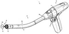
- FIG. 1is a perspective view of a surgical device in accordance with an embodiment of the present disclosure
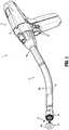
- FIG. 2is a perspective view of an adapter assembly of the surgical device of FIG. 1 ;
- FIGS. 3A and 3Bare perspective views of a distal end portion of the adapter assembly of FIGS. 1 and 2 , with an outer sleeve of the adapter assembly removed;
- FIG. 3Cis an enlarged perspective view of a part of the distal end portion of FIGS. 3A and 3B ;
- FIG. 4Ais a perspective view of a trocar connection housing disposed in the distal end portion of the adapter assembly of FIGS. 3A-3C ;
- FIGS. 4B and 4Care perspective views of proximal and distal surfaces, respectively, of a substrate of a force sensor disposed in the distal end portion of the adapter assembly of FIGS. 3A-3C ;
- FIG. 5is a perspective view of the substrate of the force sensor of FIGS. 3A-3C, 4B, and 4C in accordance with an embodiment of the present disclosure
- FIG. 6Ais a perspective view of a substrate of a force sensor in accordance with another embodiment of the present disclosure.
- FIG. 6Bis a close-up view of a groove defined in the substrate of FIG. 6A ;
- FIGS. 7A and 7Bare perspective views of the substrate of FIGS. 6A and 6B , including a flex cable and a substrate ground tab.
- proximalrefers to a portion of a device, or component thereof, that is closer to a hand of a user
- distalrefers to a portion of the device, or component thereof, that is farther from the hand of the user
- a surgical device 1in accordance with an embodiment of the present disclosure, is in the form of a powered handheld electromechanical instrument, and includes a powered handle assembly 10 , an adapter assembly 20 , and a tool assembly or end effector 30 including a loading unit 32 having a plurality of staples (not shown) disposed therein and an anvil assembly 34 including an anvil head 34 a and an anvil rod 34 b .
- the powered handle assembly 10is configured for selective connection with the adapter assembly 20 and, in turn, the adapter assembly 20 is configured for selective connection with the end effector 30 .
- the handle assembly 10includes a handle housing 12 housing a power-pack (not shown) configured to power and control various operations of the surgical device 1 , and a plurality of actuators 14 (e.g., finger-actuated control buttons, knobs, toggles, slides, interfaces, and the like) for activating various functions of the surgical device 1 .
- a power-packnot shown
- actuators 14e.g., finger-actuated control buttons, knobs, toggles, slides, interfaces, and the like
- the adapter assembly 20includes a proximal portion 20 a configured for operable connection to the handle assembly 10 ( FIG. 1 ) and a distal portion 20 b configured for operable connection to the end effector 30 (FIG. 1 ).
- the adapter assembly 20includes an outer sleeve 22 , and a connector housing 24 secured to a distal end of the outer sleeve 22 .
- the connector housing 24is configured to releasably secure an end effector, e.g., the end effector 30 ( FIG. 1 ), to the adapter assembly 20 .
- the adapter assembly 20will only further be described to the extent necessary to fully disclose the aspects of the present disclosure.
- the adapter assembly 20further includes a trocar assembly 26 that extends through a central aperture 101 ( FIG. 4B ) of a force sensor 100 and a central aperture 29 ( FIG. 4A ) of a trocar connection housing 28 .
- the trocar connection housing 28releasably secures the trocar assembly 26 relative to the outer sleeve 22 ( FIG. 2 ) of the adapter assembly 20 .
- U.S. patent application Ser. No. 14/865,602(“the '602 application”), filed on Sep. 25, 2015, the entire contents of which are incorporated herein by reference.
- the force sensor 100is disposed between the trocar connection housing 28 and the connector housing 24 of the adapter assembly 20 , and is configured to measure forces along a load path.
- the trocar connection housing 28FIG. 4A
- the trocar connection housing 28FIG. 4A
- the trocar connection housing 28includes a distal surface 28 a which interfaces with, and loads a proximal surface 102 a ( FIG. 4B ) of a body or substrate 102 of the force sensor 100 at proximal load contact areas “Cp”.
- a proximal surface 24 aFIG.
- the connector housing 24defines a contact surface which loads a distal surface 102 b of the substrate 102 of the force sensor 100 at distal load contact areas “Cd” ( FIG. 4C ).
- the anvil head 34 aapplies uniform pressure in the direction of arrow “A” ( FIG. 3A ) against the distal end 24 b of the connector housing 24 which, in turn, is transmitted to the distal load contact areas “Cd” of the force sensor 100 .
- the distal surface 102 b of the substrate 102also defines a sensing area “S” onto which sensing element “Se” (shown in phantom), e.g., strain gauges, are secured.
- the sensing elements “Se”may be distributed on the distal surface 102 b and connected in a variety of configurations, as it within the purview of those skilled in the art.
- the distal surface 102 b of the substrate 102is a generally planar surface having a plurality of grooves 110 defined therein.
- the plurality of grooves 110provide an area of separation between the distal load contact area “Cd” and the sensing area “S” of the distal surface 102 b of the substrate 102 .
- the plurality of grooves 110may be micro-trenches, relief cuts, among other depressed interruptions formed in the distal surface 102 b.
- the plurality of grooves 110may have any width, depth, and/or shape that interrupts the distal surface 102 b of the substrate 102 .
- the plurality of grooves 110have a width of about 0.01 mm and a depth of about 0.01 mm.
- the plurality of grooves 110are shown having a rectangular cross-sectional shape, it should be understood that the shape of the plurality of grooves 110 may also vary, e.g., the plurality of grooves 110 may assume a triangular, arcuate, polygonal, uniform, non-uniform, and/or tapered shape.
- the plurality of grooves 110may have any size and geometry that interrupts the distal surface 102 b of the substrate 102 to allow, for example, a coating to be masked, cut, or to break without affecting the sensing area “S” of the substrate 102 .
- the plurality of grooves 110define score lines, tape lines, or break lines in the distal surface 102 b of the substrate 102 for coating(s).
- the sensing area “S” of the distal surface 102 b of the substrate 102is a flat continuous surface, and the sensing elements “Se” ( FIG. 4C ) are placed in large strain regions of flex in the sensing area “S.”
- the sensing area “S” of the substrate 102is free of direct contact with the distal load contacting areas “Cd” via the plurality of grooves 110 thereby minimizing and/or preventing damage to the sensing element “Se” ( FIG. 4C ) and/or associated components thereof (e.g., layers, coatings, circuitry, solder connections, etc.) as the sensing elements and/or other associated components are not subjected to the direct loading at the distal load contact areas “Cd.”
- the coatingsmay terminate at the plurality of grooves 110 , without the need for masking processes, thereby minimizing or preventing tearing of the coatings in regions near the distal load contact areas “Cd” during loading of the force sensor 100 .
- the plurality of grooves 110allow for easier masking of the distal load contact areas “Cd” during fabrication of the force sensor 100 .
- the plurality of grooves 110provide break-away zones in which layers of the sensing elements and/or coatings thereon are forced to break thereby maintaining the integrity of the sensing area “S” of the substrate 102 .
- the plurality of grooves 110provides a region allowing for easy cutting, e.g., with a knife or razor, to separate the coating from distal load contact areas “Cd.”
- FIGS. 6A and 6Banother embodiment of a force sensor substrate 102 ′ is illustrated.
- the substrate 102 ′is similar to substrate 102 and therefore described with respect to the differences therebetween.
- the force sensor substrate 102 ′includes a proximal surface 102 a ( FIG. 4B ) and a distal surface 102 b ′ defining distal load contact areas “Cd” and a sensing area “S”.
- a groove 110 ′is formed in the sensing area “S” to isolate a desired solder contact surface in the sensing area “S” to create a localized region of reduced strain.
- the groove 110 ′includes a series of connected parallel cuts 111 , each cut having a peninsula-like configuration.
- one or more grooves 110 ′may be formed in a variety of arrangement, e.g., different shapes, depths, and/or widths, to transfer the strain beneath the distal surface 102 b ′ of the substrate 102 ′.
- the geometry of the groove 110 ′corresponds to an end 120 a of a flex cable 120 , thereby reducing the strain, under load, at the surface of solder joints (not shown) formed between the end 120 a of the flex cable 120 and the solder contact surface in the groove 110 ′.
- the integrity of the solder connectionsare enhanced.
Landscapes
- Health & Medical Sciences (AREA)
- Surgery (AREA)
- Life Sciences & Earth Sciences (AREA)
- Engineering & Computer Science (AREA)
- General Physics & Mathematics (AREA)
- Physics & Mathematics (AREA)
- Veterinary Medicine (AREA)
- General Health & Medical Sciences (AREA)
- Biomedical Technology (AREA)
- Heart & Thoracic Surgery (AREA)
- Medical Informatics (AREA)
- Molecular Biology (AREA)
- Animal Behavior & Ethology (AREA)
- Nuclear Medicine, Radiotherapy & Molecular Imaging (AREA)
- Public Health (AREA)
- Robotics (AREA)
- Chemical & Material Sciences (AREA)
- Analytical Chemistry (AREA)
- Human Computer Interaction (AREA)
- Force Measurement Appropriate To Specific Purposes (AREA)
- Manipulator (AREA)
- Surgical Instruments (AREA)
Abstract
Description
This application claims the benefit of and priority to U.S. Provisional Patent Application No. 62/375,012 filed Aug. 15, 2016, the entire disclosure of which is incorporated by reference herein.
The present disclosure relates generally to surgical devices. More particularly, the present disclosure relates to force sensors for powered surgical devices.
Force sensors are known, and there are multiple methods of fabricating these types of sensors. In one method, sensors utilize bonded strain gauges adhered to a flexing substrate within a load path. For example, a simply supported steel beam that is used integral to a load path can have a strain gauge mounted on the beam. The strain gauge is incorporated in a Wheatstone Bridge Circuit configuration and includes an excitation voltage. The circuit is designed to be at balance before deflection (i.e., no load) and the circuit will have a resistance at zero load. During loading, the beam will deflect and the strain gauge will produce a resistance change. This resistance change is a signal that can be converted into a force value imposed on the beam using a signal conditioner. Depending on the type of configuration (e.g., a quarter bridge, a half bridge, a full bridge), the signal will vary and require calibration to obtain the actual force imposed.
Some strain gauges incorporate a thin plastic film with a bonded NiCr (nickel-chromium or nichrome) wire path embedded on the film. When the film is bonded to the beam and the beam is deflected, the NiCr wire will also be subjected to bending causing a deformation of the wire. The deformation of the wire will cause the above mentioned change in electrical resistance.
The flexing substrate must be configured to elastically deform in an elastic region. In the event that the substrate is subjected to permanent deformation, the sensing wire of the strain gauge will be constrained in the deformed state. This will result in inaccurate subsequent readings of the sensor.
Solder connections are typically utilized in a strain gauge circuit, with the wire path of the strain gauge terminating at a pair of solder pads. Other connections are also used, such as laser welding, mechanical forcing of wires to the contact pads, etc.
The solder connections are subject to possible failures if the connections are made in areas of high strain. Such a strain can cause high levels of deformation causing the solder connections to fatigue. Depending on the level of strain, this fatigue can cause failure of the solder pad resulting in a loss of electrical signal rendering the sensor unusable.
If alternate sensors are used, e.g., those fabricated using vapor deposition of brittle materials, this phenomena can become more problematic. Sensor fabricated using vapor deposition include depositing several layers of media to create the sensor. Typically, the first layer consists of a thin layer of glass deposited along a surface that will incorporate the sensing wire. The sensing wire is first deposited along the substrate as a full NiCr covering. A laser then etches away the NiCr until the desired wire path is created having a plurality of solder pads forming a sensing element as described above with respect to the bonded strain gauge. Finally, a covering layer is used to prevent moisture ingress preventing shorts of the wire trace. The covering layer may be a cured epoxy or an RTV sealant (e.g., room temperature vulcanization silicone), or a vapor deposited glass with a region of glass etched away to gain access to the solder pads. This allows for the soldering of the wires or a flex cable to the sensor.
The configurations described above suffer from problems. One problem is the ability to load the substrate in an instrument. When utilizing glass along the substrate, the glass can crack when loaded. Another problem is premature failing due to large strains on the solder pads.
In one aspect of the present disclosure, a force sensor substrate includes a proximal surface including a proximal load contact area, and a distal surface including at least one distal load contact area and a sensing area. The distal surface is planar and has at least one groove defined therein separating the at least one distal load contact area from the sensing area.
According to another aspect of the present disclosure, a force sensor substrate includes a proximal surface including a proximal load contact area and a distal surface including a distal load contact area and a sensing area. The distal surface is planar and has at least one groove defined in the sensing area.
Embodiments can include one or more of the following advantages:
The force sensors and substrates thereof may be configured to withstand large loading forces without disrupting the surface containing the sensing electronics (e.g., sensing elements or strain gauges, and their associated components).
The force sensors and substrates thereof may be configured to prevent tear propagation of protective conformal coatings and/or layers of sensing elements disposed thereon, and/or prevent surface micro-strain from damaging solder welds.
The force sensors and substrates thereof may be configured to withstand environmental stresses associated with autowashing and/or autoclaving, thereby rendering the force sensors more durable for reuse.
Other aspects, features, and advantages will be apparent from the description, drawings, and the claims.
Various aspects of the present disclosure are described herein below with reference to the drawings, which are incorporated in and constitute a part of this specification, wherein:
Embodiments of the present disclosure are now described in detail with reference to the drawings in which like reference numerals designate identical or corresponding elements in each of the several views. Throughout this description, the term “proximal” refers to a portion of a device, or component thereof, that is closer to a hand of a user, and the term “distal” refers to a portion of the device, or component thereof, that is farther from the hand of the user.
Turning now toFIG. 1 , asurgical device 1, in accordance with an embodiment of the present disclosure, is in the form of a powered handheld electromechanical instrument, and includes apowered handle assembly 10, anadapter assembly 20, and a tool assembly orend effector 30 including aloading unit 32 having a plurality of staples (not shown) disposed therein and ananvil assembly 34 including ananvil head 34aand ananvil rod 34b. Thepowered handle assembly 10 is configured for selective connection with theadapter assembly 20 and, in turn, theadapter assembly 20 is configured for selective connection with theend effector 30.
While described and shown as includingadapter assembly 20 andend effector 30, it should be understood that a variety of different adapter assemblies and end effectors may be utilized in the surgical device of the present disclosure. For a detailed description of the structure and function of exemplary surgical devices, reference may be made to commonly owned U.S. patent application Ser. No. 14/991,157 (“the '157 application”), filed on Jan. 8, 2016, and Ser. No. 15/096,399 (“the '399 application”), filed on Apr. 12, 2016, the entire contents of each of which are incorporated herein by reference.
With continued reference toFIG. 1 , thehandle assembly 10 includes ahandle housing 12 housing a power-pack (not shown) configured to power and control various operations of thesurgical device 1, and a plurality of actuators14 (e.g., finger-actuated control buttons, knobs, toggles, slides, interfaces, and the like) for activating various functions of thesurgical device 1. For a detailed description of an exemplary handle assembly, reference may be made to the '399 application, the entire contents of which was previously incorporated herein by reference.
Referring now toFIG. 2 , in conjunction withFIG. 1 , theadapter assembly 20 includes aproximal portion 20aconfigured for operable connection to the handle assembly10 (FIG. 1 ) and adistal portion 20bconfigured for operable connection to the end effector30 (FIG.1). Theadapter assembly 20 includes anouter sleeve 22, and aconnector housing 24 secured to a distal end of theouter sleeve 22. Theconnector housing 24 is configured to releasably secure an end effector, e.g., the end effector30 (FIG. 1 ), to theadapter assembly 20.
Theadapter assembly 20 will only further be described to the extent necessary to fully disclose the aspects of the present disclosure. For detailed description of an exemplary adapter assembly, reference may be made to the '157 application, the entire contents of which was previously incorporated herein by reference.
With reference now toFIGS. 3A-3C , theadapter assembly 20 further includes atrocar assembly 26 that extends through a central aperture101 (FIG. 4B ) of aforce sensor 100 and a central aperture29 (FIG. 4A ) of atrocar connection housing 28. Thetrocar connection housing 28 releasably secures thetrocar assembly 26 relative to the outer sleeve22 (FIG. 2 ) of theadapter assembly 20. For a detailed description of an exemplary trocar connection housing, reference may be made to U.S. patent application Ser. No. 14/865,602 (“the '602 application”), filed on Sep. 25, 2015, the entire contents of which are incorporated herein by reference.
Theforce sensor 100 is disposed between thetrocar connection housing 28 and theconnector housing 24 of theadapter assembly 20, and is configured to measure forces along a load path. As shown inFIGS. 4A and 4B , in conjunction withFIG. 3C , the trocar connection housing28 (FIG. 4A ) includes adistal surface 28awhich interfaces with, and loads aproximal surface 102a(FIG. 4B ) of a body orsubstrate 102 of theforce sensor 100 at proximal load contact areas “Cp”. As shown inFIG. 4C , in conjunction withFIG. 3C , aproximal surface 24a(FIG. 3C ) of theconnector housing 24 defines a contact surface which loads adistal surface 102bof thesubstrate 102 of theforce sensor 100 at distal load contact areas “Cd” (FIG. 4C ). Thus, for example, as the anvil assembly34 (FIG. 1 ) is approximated towards theloading unit 32 of theend effector 30 during clamping and/or stapling of tissue, theanvil head 34aapplies uniform pressure in the direction of arrow “A” (FIG. 3A ) against thedistal end 24bof theconnector housing 24 which, in turn, is transmitted to the distal load contact areas “Cd” of theforce sensor 100.
As shown inFIG. 4C , thedistal surface 102bof thesubstrate 102 also defines a sensing area “S” onto which sensing element “Se” (shown in phantom), e.g., strain gauges, are secured. The sensing elements “Se” may be distributed on thedistal surface 102band connected in a variety of configurations, as it within the purview of those skilled in the art.
With reference now toFIG. 5 , thedistal surface 102bof thesubstrate 102 is a generally planar surface having a plurality ofgrooves 110 defined therein. The plurality ofgrooves 110 provide an area of separation between the distal load contact area “Cd” and the sensing area “S” of thedistal surface 102bof thesubstrate 102. The plurality ofgrooves 110 may be micro-trenches, relief cuts, among other depressed interruptions formed in thedistal surface 102b.
The plurality ofgrooves 110 may have any width, depth, and/or shape that interrupts thedistal surface 102bof thesubstrate 102. In embodiments, the plurality ofgrooves 110 have a width of about 0.01 mm and a depth of about 0.01 mm. Moreover, while the plurality ofgrooves 110 are shown having a rectangular cross-sectional shape, it should be understood that the shape of the plurality ofgrooves 110 may also vary, e.g., the plurality ofgrooves 110 may assume a triangular, arcuate, polygonal, uniform, non-uniform, and/or tapered shape. The plurality ofgrooves 110 may have any size and geometry that interrupts thedistal surface 102bof thesubstrate 102 to allow, for example, a coating to be masked, cut, or to break without affecting the sensing area “S” of thesubstrate 102. In embodiments, the plurality ofgrooves 110 define score lines, tape lines, or break lines in thedistal surface 102bof thesubstrate 102 for coating(s).
The sensing area “S” of thedistal surface 102bof thesubstrate 102 is a flat continuous surface, and the sensing elements “Se” (FIG. 4C ) are placed in large strain regions of flex in the sensing area “S.” The sensing area “S” of thesubstrate 102 is free of direct contact with the distal load contacting areas “Cd” via the plurality ofgrooves 110 thereby minimizing and/or preventing damage to the sensing element “Se” (FIG. 4C ) and/or associated components thereof (e.g., layers, coatings, circuitry, solder connections, etc.) as the sensing elements and/or other associated components are not subjected to the direct loading at the distal load contact areas “Cd.”
In embodiments in which coatings are utilized to protect the circuitry and/or solder connections (not shown) disposed on the sensing area “S” of thesubstrate 102, the coatings may terminate at the plurality ofgrooves 110, without the need for masking processes, thereby minimizing or preventing tearing of the coatings in regions near the distal load contact areas “Cd” during loading of theforce sensor 100.
In embodiments in which masking is desired, the plurality ofgrooves 110 allow for easier masking of the distal load contact areas “Cd” during fabrication of theforce sensor 100. The plurality ofgrooves 110 provide break-away zones in which layers of the sensing elements and/or coatings thereon are forced to break thereby maintaining the integrity of the sensing area “S” of thesubstrate 102. In embodiments, the plurality ofgrooves 110 provides a region allowing for easy cutting, e.g., with a knife or razor, to separate the coating from distal load contact areas “Cd.”
Referring now toFIGS. 6A and 6B , another embodiment of aforce sensor substrate 102′ is illustrated. Thesubstrate 102′ is similar tosubstrate 102 and therefore described with respect to the differences therebetween.
Theforce sensor substrate 102′ includes aproximal surface 102a(FIG. 4B ) and adistal surface 102b′ defining distal load contact areas “Cd” and a sensing area “S”. Agroove 110′ is formed in the sensing area “S” to isolate a desired solder contact surface in the sensing area “S” to create a localized region of reduced strain. Thegroove 110′ includes a series of connectedparallel cuts 111, each cut having a peninsula-like configuration. It should be understood, however, that one ormore grooves 110′ may be formed in a variety of arrangement, e.g., different shapes, depths, and/or widths, to transfer the strain beneath thedistal surface 102b′ of thesubstrate 102′.
As shown inFIGS. 7A and 7B , the geometry of thegroove 110′ corresponds to anend 120aof aflex cable 120, thereby reducing the strain, under load, at the surface of solder joints (not shown) formed between theend 120aof theflex cable 120 and the solder contact surface in thegroove 110′. With the reduction of strain atdistal surface 102b′ of thesubstrate 102′, the integrity of the solder connections are enhanced.
While several embodiments of the disclosure have been shown in the drawings, it is not intended that the disclosure be limited thereto, as it is intended that the disclosure be as broad in scope as the art will allow and that the specification be read likewise. Any combination of the above embodiments is also envisioned and is within the scope of the appended claims. Therefore, the above description should not be construed as limiting, but merely as exemplifications of particular embodiments. Those skilled in the art will envision other modifications within the scope of the claims appended hereto.
Claims (10)
1. An adapter assembly for selectively interconnecting an end effector configured to perform a function and a handle assembly configured to actuate the end effector, the adapter assembly comprising:
an outer sleeve;
a connector housing secured to a distal end of the outer sleeve;
a trocar connection housing disposed within the outer sleeve; and
a force sensor disposed between the connector housing and the trocar connection housing, the force sensor including a substrate including a proximal surface having a proximal load contact area and a distal surface having at least one distal load contact area and a sensing area, the distal surface being planar and having at least one groove defined therein separating the at least one distal load contact area from the sensing area.
2. The adapter assembly according toclaim 1 , wherein the trocar connection housing includes a distal surface that interfaces with and loads the proximal surface of the force sensor at the proximal load contact area, and the connector housing includes a proximal surface that interfaces with and loads the distal surface of the force sensor at the at least one distal load contact area.
3. The adapter assembly according toclaim 1 , further including a trocar assembly extending through a central aperture of the force sensor and a central aperture of the trocar connection housing.
4. The adapter assembly according toclaim 3 , wherein the proximal load contact area of the force sensor is disposed adjacent to the central aperture of the force sensor.
5. The adapter assembly according toclaim 1 , wherein the at least one distal load contact area of the force sensor includes four distal load contact areas disposed at corners of the substrate.
6. The adapter assembly according toclaim 1 , wherein the sensing area of the force sensor is a flat continuous surface including sensing elements dispose thereon, the sensing area is free from direct contact with the at least one distal load contacting area via the at least one groove.
7. The adapter assembly according toclaim 6 , wherein the sensing elements are strain gauges.
8. The adapter assembly according toclaim 1 , wherein a coating is disposed over the sensing area of the force sensor and terminates at the at least one groove.
9. The adapter assembly according toclaim 1 , wherein the force sensor includes a groove defined in the sensing area.
10. The adapter assembly according toclaim 9 , further including a flex cable coupled to the groove of the sensing area via solder joints.
Priority Applications (6)
| Application Number | Priority Date | Filing Date | Title |
|---|---|---|---|
| US15/665,789US10595951B2 (en) | 2016-08-15 | 2017-08-01 | Force sensor for surgical devices |
| CN201710691386.9ACN107764440B (en) | 2016-08-15 | 2017-08-14 | Force sensor for surgical device |
| ES17186269TES2930056T3 (en) | 2016-08-15 | 2017-08-15 | Force sensor for surgical devices |
| EP17186269.1AEP3285056B1 (en) | 2016-08-15 | 2017-08-15 | Force sensor for surgical devices |
| US16/714,005US11058506B2 (en) | 2016-08-15 | 2019-12-13 | Force sensor for surgical devices |
| US17/365,125US11786330B2 (en) | 2016-08-15 | 2021-07-01 | Force sensor for surgical devices |
Applications Claiming Priority (2)
| Application Number | Priority Date | Filing Date | Title |
|---|---|---|---|
| US201662375012P | 2016-08-15 | 2016-08-15 | |
| US15/665,789US10595951B2 (en) | 2016-08-15 | 2017-08-01 | Force sensor for surgical devices |
Related Child Applications (1)
| Application Number | Title | Priority Date | Filing Date |
|---|---|---|---|
| US16/714,005DivisionUS11058506B2 (en) | 2016-08-15 | 2019-12-13 | Force sensor for surgical devices |
Publications (2)
| Publication Number | Publication Date |
|---|---|
| US20180042689A1 US20180042689A1 (en) | 2018-02-15 |
| US10595951B2true US10595951B2 (en) | 2020-03-24 |
Family
ID=59745706
Family Applications (3)
| Application Number | Title | Priority Date | Filing Date |
|---|---|---|---|
| US15/665,789Active2038-02-21US10595951B2 (en) | 2016-08-15 | 2017-08-01 | Force sensor for surgical devices |
| US16/714,005Expired - Fee RelatedUS11058506B2 (en) | 2016-08-15 | 2019-12-13 | Force sensor for surgical devices |
| US17/365,125Active2037-11-29US11786330B2 (en) | 2016-08-15 | 2021-07-01 | Force sensor for surgical devices |
Family Applications After (2)
| Application Number | Title | Priority Date | Filing Date |
|---|---|---|---|
| US16/714,005Expired - Fee RelatedUS11058506B2 (en) | 2016-08-15 | 2019-12-13 | Force sensor for surgical devices |
| US17/365,125Active2037-11-29US11786330B2 (en) | 2016-08-15 | 2021-07-01 | Force sensor for surgical devices |
Country Status (4)
| Country | Link |
|---|---|
| US (3) | US10595951B2 (en) |
| EP (1) | EP3285056B1 (en) |
| CN (1) | CN107764440B (en) |
| ES (1) | ES2930056T3 (en) |
Families Citing this family (178)
| Publication number | Priority date | Publication date | Assignee | Title |
|---|---|---|---|---|
| US9060770B2 (en) | 2003-05-20 | 2015-06-23 | Ethicon Endo-Surgery, Inc. | Robotically-driven surgical instrument with E-beam driver |
| US20070084897A1 (en) | 2003-05-20 | 2007-04-19 | Shelton Frederick E Iv | Articulating surgical stapling instrument incorporating a two-piece e-beam firing mechanism |
| US11998198B2 (en) | 2004-07-28 | 2024-06-04 | Cilag Gmbh International | Surgical stapling instrument incorporating a two-piece E-beam firing mechanism |
| US9072535B2 (en) | 2011-05-27 | 2015-07-07 | Ethicon Endo-Surgery, Inc. | Surgical stapling instruments with rotatable staple deployment arrangements |
| US11890012B2 (en) | 2004-07-28 | 2024-02-06 | Cilag Gmbh International | Staple cartridge comprising cartridge body and attached support |
| US8496647B2 (en) | 2007-12-18 | 2013-07-30 | Intuitive Surgical Operations, Inc. | Ribbed force sensor |
| US10159482B2 (en) | 2005-08-31 | 2018-12-25 | Ethicon Llc | Fastener cartridge assembly comprising a fixed anvil and different staple heights |
| US7669746B2 (en) | 2005-08-31 | 2010-03-02 | Ethicon Endo-Surgery, Inc. | Staple cartridges for forming staples having differing formed staple heights |
| US11246590B2 (en) | 2005-08-31 | 2022-02-15 | Cilag Gmbh International | Staple cartridge including staple drivers having different unfired heights |
| US8628518B2 (en) | 2005-12-30 | 2014-01-14 | Intuitive Surgical Operations, Inc. | Wireless force sensor on a distal portion of a surgical instrument and method |
| US8186555B2 (en) | 2006-01-31 | 2012-05-29 | Ethicon Endo-Surgery, Inc. | Motor-driven surgical cutting and fastening instrument with mechanical closure system |
| US8708213B2 (en) | 2006-01-31 | 2014-04-29 | Ethicon Endo-Surgery, Inc. | Surgical instrument having a feedback system |
| US11793518B2 (en) | 2006-01-31 | 2023-10-24 | Cilag Gmbh International | Powered surgical instruments with firing system lockout arrangements |
| US20120292367A1 (en) | 2006-01-31 | 2012-11-22 | Ethicon Endo-Surgery, Inc. | Robotically-controlled end effector |
| US7845537B2 (en) | 2006-01-31 | 2010-12-07 | Ethicon Endo-Surgery, Inc. | Surgical instrument having recording capabilities |
| US8992422B2 (en) | 2006-03-23 | 2015-03-31 | Ethicon Endo-Surgery, Inc. | Robotically-controlled endoscopic accessory channel |
| US11980366B2 (en) | 2006-10-03 | 2024-05-14 | Cilag Gmbh International | Surgical instrument |
| US8632535B2 (en) | 2007-01-10 | 2014-01-21 | Ethicon Endo-Surgery, Inc. | Interlock and surgical instrument including same |
| US8684253B2 (en) | 2007-01-10 | 2014-04-01 | Ethicon Endo-Surgery, Inc. | Surgical instrument with wireless communication between a control unit of a robotic system and remote sensor |
| US20080169333A1 (en) | 2007-01-11 | 2008-07-17 | Shelton Frederick E | Surgical stapler end effector with tapered distal end |
| US8931682B2 (en) | 2007-06-04 | 2015-01-13 | Ethicon Endo-Surgery, Inc. | Robotically-controlled shaft based rotary drive systems for surgical instruments |
| US11564682B2 (en) | 2007-06-04 | 2023-01-31 | Cilag Gmbh International | Surgical stapler device |
| US11849941B2 (en) | 2007-06-29 | 2023-12-26 | Cilag Gmbh International | Staple cartridge having staple cavities extending at a transverse angle relative to a longitudinal cartridge axis |
| US8561473B2 (en) | 2007-12-18 | 2013-10-22 | Intuitive Surgical Operations, Inc. | Force sensor temperature compensation |
| US8573465B2 (en) | 2008-02-14 | 2013-11-05 | Ethicon Endo-Surgery, Inc. | Robotically-controlled surgical end effector system with rotary actuated closure systems |
| JP5410110B2 (en) | 2008-02-14 | 2014-02-05 | エシコン・エンド−サージェリィ・インコーポレイテッド | Surgical cutting / fixing instrument with RF electrode |
| US11986183B2 (en) | 2008-02-14 | 2024-05-21 | Cilag Gmbh International | Surgical cutting and fastening instrument comprising a plurality of sensors to measure an electrical parameter |
| US8636736B2 (en) | 2008-02-14 | 2014-01-28 | Ethicon Endo-Surgery, Inc. | Motorized surgical cutting and fastening instrument |
| US9585657B2 (en) | 2008-02-15 | 2017-03-07 | Ethicon Endo-Surgery, Llc | Actuator for releasing a layer of material from a surgical end effector |
| US9005230B2 (en) | 2008-09-23 | 2015-04-14 | Ethicon Endo-Surgery, Inc. | Motorized surgical instrument |
| US9386983B2 (en) | 2008-09-23 | 2016-07-12 | Ethicon Endo-Surgery, Llc | Robotically-controlled motorized surgical instrument |
| US8210411B2 (en) | 2008-09-23 | 2012-07-03 | Ethicon Endo-Surgery, Inc. | Motor-driven surgical cutting instrument |
| US8608045B2 (en) | 2008-10-10 | 2013-12-17 | Ethicon Endo-Sugery, Inc. | Powered surgical cutting and stapling apparatus with manually retractable firing system |
| US9788834B2 (en) | 2010-09-30 | 2017-10-17 | Ethicon Llc | Layer comprising deployable attachment members |
| US12213666B2 (en) | 2010-09-30 | 2025-02-04 | Cilag Gmbh International | Tissue thickness compensator comprising layers |
| US11925354B2 (en) | 2010-09-30 | 2024-03-12 | Cilag Gmbh International | Staple cartridge comprising staples positioned within a compressible portion thereof |
| US9386988B2 (en) | 2010-09-30 | 2016-07-12 | Ethicon End-Surgery, LLC | Retainer assembly including a tissue thickness compensator |
| US11812965B2 (en) | 2010-09-30 | 2023-11-14 | Cilag Gmbh International | Layer of material for a surgical end effector |
| US9629814B2 (en) | 2010-09-30 | 2017-04-25 | Ethicon Endo-Surgery, Llc | Tissue thickness compensator configured to redistribute compressive forces |
| US10945731B2 (en) | 2010-09-30 | 2021-03-16 | Ethicon Llc | Tissue thickness compensator comprising controlled release and expansion |
| AU2012250197B2 (en) | 2011-04-29 | 2017-08-10 | Ethicon Endo-Surgery, Inc. | Staple cartridge comprising staples positioned within a compressible portion thereof |
| US11207064B2 (en) | 2011-05-27 | 2021-12-28 | Cilag Gmbh International | Automated end effector component reloading system for use with a robotic system |
| BR112014024098B1 (en) | 2012-03-28 | 2021-05-25 | Ethicon Endo-Surgery, Inc. | staple cartridge |
| MX358135B (en) | 2012-03-28 | 2018-08-06 | Ethicon Endo Surgery Inc | Tissue thickness compensator comprising a plurality of layers. |
| US9101358B2 (en) | 2012-06-15 | 2015-08-11 | Ethicon Endo-Surgery, Inc. | Articulatable surgical instrument comprising a firing drive |
| US9289256B2 (en) | 2012-06-28 | 2016-03-22 | Ethicon Endo-Surgery, Llc | Surgical end effectors having angled tissue-contacting surfaces |
| US20140001231A1 (en) | 2012-06-28 | 2014-01-02 | Ethicon Endo-Surgery, Inc. | Firing system lockout arrangements for surgical instruments |
| US12383267B2 (en) | 2012-06-28 | 2025-08-12 | Cilag Gmbh International | Robotically powered surgical device with manually-actuatable reversing system |
| RU2672520C2 (en) | 2013-03-01 | 2018-11-15 | Этикон Эндо-Серджери, Инк. | Hingedly turnable surgical instruments with conducting ways for signal transfer |
| BR112015021082B1 (en) | 2013-03-01 | 2022-05-10 | Ethicon Endo-Surgery, Inc | surgical instrument |
| US9629629B2 (en) | 2013-03-14 | 2017-04-25 | Ethicon Endo-Surgey, LLC | Control systems for surgical instruments |
| BR112015026109B1 (en) | 2013-04-16 | 2022-02-22 | Ethicon Endo-Surgery, Inc | surgical instrument |
| US9775609B2 (en) | 2013-08-23 | 2017-10-03 | Ethicon Llc | Tamper proof circuit for surgical instrument battery pack |
| US10013049B2 (en) | 2014-03-26 | 2018-07-03 | Ethicon Llc | Power management through sleep options of segmented circuit and wake up control |
| US12232723B2 (en) | 2014-03-26 | 2025-02-25 | Cilag Gmbh International | Systems and methods for controlling a segmented circuit |
| US20150272580A1 (en) | 2014-03-26 | 2015-10-01 | Ethicon Endo-Surgery, Inc. | Verification of number of battery exchanges/procedure count |
| BR112016023825B1 (en) | 2014-04-16 | 2022-08-02 | Ethicon Endo-Surgery, Llc | STAPLE CARTRIDGE FOR USE WITH A SURGICAL STAPLER AND STAPLE CARTRIDGE FOR USE WITH A SURGICAL INSTRUMENT |
| US10327764B2 (en) | 2014-09-26 | 2019-06-25 | Ethicon Llc | Method for creating a flexible staple line |
| US20150297225A1 (en) | 2014-04-16 | 2015-10-22 | Ethicon Endo-Surgery, Inc. | Fastener cartridges including extensions having different configurations |
| CN106456176B (en) | 2014-04-16 | 2019-06-28 | 伊西康内外科有限责任公司 | Fastener Cartridge Including Extensions With Different Configurations |
| CN106456159B (en) | 2014-04-16 | 2019-03-08 | 伊西康内外科有限责任公司 | Fastener Cartridge Assembly and Nail Retainer Cover Arrangement |
| US11311294B2 (en) | 2014-09-05 | 2022-04-26 | Cilag Gmbh International | Powered medical device including measurement of closure state of jaws |
| BR112017004361B1 (en) | 2014-09-05 | 2023-04-11 | Ethicon Llc | ELECTRONIC SYSTEM FOR A SURGICAL INSTRUMENT |
| US10105142B2 (en) | 2014-09-18 | 2018-10-23 | Ethicon Llc | Surgical stapler with plurality of cutting elements |
| US11523821B2 (en) | 2014-09-26 | 2022-12-13 | Cilag Gmbh International | Method for creating a flexible staple line |
| US9924944B2 (en) | 2014-10-16 | 2018-03-27 | Ethicon Llc | Staple cartridge comprising an adjunct material |
| US10517594B2 (en) | 2014-10-29 | 2019-12-31 | Ethicon Llc | Cartridge assemblies for surgical staplers |
| US10736636B2 (en) | 2014-12-10 | 2020-08-11 | Ethicon Llc | Articulatable surgical instrument system |
| US9987000B2 (en) | 2014-12-18 | 2018-06-05 | Ethicon Llc | Surgical instrument assembly comprising a flexible articulation system |
| US10085748B2 (en) | 2014-12-18 | 2018-10-02 | Ethicon Llc | Locking arrangements for detachable shaft assemblies with articulatable surgical end effectors |
| US11154301B2 (en) | 2015-02-27 | 2021-10-26 | Cilag Gmbh International | Modular stapling assembly |
| US10441279B2 (en) | 2015-03-06 | 2019-10-15 | Ethicon Llc | Multiple level thresholds to modify operation of powered surgical instruments |
| US10433844B2 (en) | 2015-03-31 | 2019-10-08 | Ethicon Llc | Surgical instrument with selectively disengageable threaded drive systems |
| US10105139B2 (en) | 2015-09-23 | 2018-10-23 | Ethicon Llc | Surgical stapler having downstream current-based motor control |
| US10299878B2 (en) | 2015-09-25 | 2019-05-28 | Ethicon Llc | Implantable adjunct systems for determining adjunct skew |
| US10433846B2 (en) | 2015-09-30 | 2019-10-08 | Ethicon Llc | Compressible adjunct with crossing spacer fibers |
| US11890015B2 (en) | 2015-09-30 | 2024-02-06 | Cilag Gmbh International | Compressible adjunct with crossing spacer fibers |
| US10478188B2 (en) | 2015-09-30 | 2019-11-19 | Ethicon Llc | Implantable layer comprising a constricted configuration |
| US10265068B2 (en) | 2015-12-30 | 2019-04-23 | Ethicon Llc | Surgical instruments with separable motors and motor control circuits |
| US10292704B2 (en) | 2015-12-30 | 2019-05-21 | Ethicon Llc | Mechanisms for compensating for battery pack failure in powered surgical instruments |
| US11213293B2 (en) | 2016-02-09 | 2022-01-04 | Cilag Gmbh International | Articulatable surgical instruments with single articulation link arrangements |
| US10448948B2 (en) | 2016-02-12 | 2019-10-22 | Ethicon Llc | Mechanisms for compensating for drivetrain failure in powered surgical instruments |
| US10828028B2 (en) | 2016-04-15 | 2020-11-10 | Ethicon Llc | Surgical instrument with multiple program responses during a firing motion |
| US10357247B2 (en) | 2016-04-15 | 2019-07-23 | Ethicon Llc | Surgical instrument with multiple program responses during a firing motion |
| US20170296173A1 (en) | 2016-04-18 | 2017-10-19 | Ethicon Endo-Surgery, Llc | Method for operating a surgical instrument |
| US10500000B2 (en) | 2016-08-16 | 2019-12-10 | Ethicon Llc | Surgical tool with manual control of end effector jaws |
| JP7010957B2 (en) | 2016-12-21 | 2022-01-26 | エシコン エルエルシー | Shaft assembly with lockout |
| JP7010956B2 (en) | 2016-12-21 | 2022-01-26 | エシコン エルエルシー | How to staple tissue |
| US10813638B2 (en) | 2016-12-21 | 2020-10-27 | Ethicon Llc | Surgical end effectors with expandable tissue stop arrangements |
| US20180168625A1 (en) | 2016-12-21 | 2018-06-21 | Ethicon Endo-Surgery, Llc | Surgical stapling instruments with smart staple cartridges |
| US11090048B2 (en) | 2016-12-21 | 2021-08-17 | Cilag Gmbh International | Method for resetting a fuse of a surgical instrument shaft |
| US10973516B2 (en) | 2016-12-21 | 2021-04-13 | Ethicon Llc | Surgical end effectors and adaptable firing members therefor |
| US10779820B2 (en) | 2017-06-20 | 2020-09-22 | Ethicon Llc | Systems and methods for controlling motor speed according to user input for a surgical instrument |
| US10307170B2 (en) | 2017-06-20 | 2019-06-04 | Ethicon Llc | Method for closed loop control of motor velocity of a surgical stapling and cutting instrument |
| EP3420947B1 (en) | 2017-06-28 | 2022-05-25 | Cilag GmbH International | Surgical instrument comprising selectively actuatable rotatable couplers |
| US11484310B2 (en) | 2017-06-28 | 2022-11-01 | Cilag Gmbh International | Surgical instrument comprising a shaft including a closure tube profile |
| USD906355S1 (en) | 2017-06-28 | 2020-12-29 | Ethicon Llc | Display screen or portion thereof with a graphical user interface for a surgical instrument |
| US10932772B2 (en) | 2017-06-29 | 2021-03-02 | Ethicon Llc | Methods for closed loop velocity control for robotic surgical instrument |
| US11944300B2 (en) | 2017-08-03 | 2024-04-02 | Cilag Gmbh International | Method for operating a surgical system bailout |
| US11974742B2 (en) | 2017-08-03 | 2024-05-07 | Cilag Gmbh International | Surgical system comprising an articulation bailout |
| US11134944B2 (en) | 2017-10-30 | 2021-10-05 | Cilag Gmbh International | Surgical stapler knife motion controls |
| US10842490B2 (en) | 2017-10-31 | 2020-11-24 | Ethicon Llc | Cartridge body design with force reduction based on firing completion |
| US10675107B2 (en) | 2017-11-15 | 2020-06-09 | Intuitive Surgical Operations, Inc. | Surgical instrument end effector with integral FBG |
| US10779826B2 (en) | 2017-12-15 | 2020-09-22 | Ethicon Llc | Methods of operating surgical end effectors |
| US10835330B2 (en) | 2017-12-19 | 2020-11-17 | Ethicon Llc | Method for determining the position of a rotatable jaw of a surgical instrument attachment assembly |
| US12336705B2 (en) | 2017-12-21 | 2025-06-24 | Cilag Gmbh International | Continuous use self-propelled stapling instrument |
| US11179151B2 (en) | 2017-12-21 | 2021-11-23 | Cilag Gmbh International | Surgical instrument comprising a display |
| WO2019227032A1 (en) | 2018-05-25 | 2019-11-28 | Intuitive Surgical Operations, Inc. | Fiber bragg grating end effector force sensor |
| US20200054321A1 (en) | 2018-08-20 | 2020-02-20 | Ethicon Llc | Surgical instruments with progressive jaw closure arrangements |
| US11207065B2 (en) | 2018-08-20 | 2021-12-28 | Cilag Gmbh International | Method for fabricating surgical stapler anvils |
| US11291440B2 (en) | 2018-08-20 | 2022-04-05 | Cilag Gmbh International | Method for operating a powered articulatable surgical instrument |
| US11717276B2 (en)* | 2018-10-30 | 2023-08-08 | Covidien Lp | Surgical devices including adapters and seals |
| US12419713B2 (en) | 2018-11-15 | 2025-09-23 | Intuitive Surgical Operations, Inc. | Surgical instrument with sensor aligned cable guide |
| WO2020102776A1 (en) | 2018-11-15 | 2020-05-22 | Intuitive Surgical Operations, Inc. | Surgical instrument with sensor aligned cable guide |
| WO2020102778A1 (en) | 2018-11-15 | 2020-05-22 | Intuitive Surgical Operations, Inc. | Strain sensor with contoured deflection surface |
| US11219461B2 (en)* | 2019-03-08 | 2022-01-11 | Covidien Lp | Strain gauge stabilization in a surgical device |
| US11696761B2 (en) | 2019-03-25 | 2023-07-11 | Cilag Gmbh International | Firing drive arrangements for surgical systems |
| US20200345359A1 (en) | 2019-04-30 | 2020-11-05 | Ethicon Llc | Tissue stop for a surgical instrument |
| US11903581B2 (en) | 2019-04-30 | 2024-02-20 | Cilag Gmbh International | Methods for stapling tissue using a surgical instrument |
| US11684434B2 (en) | 2019-06-28 | 2023-06-27 | Cilag Gmbh International | Surgical RFID assemblies for instrument operational setting control |
| US11241235B2 (en) | 2019-06-28 | 2022-02-08 | Cilag Gmbh International | Method of using multiple RFID chips with a surgical assembly |
| US11771419B2 (en) | 2019-06-28 | 2023-10-03 | Cilag Gmbh International | Packaging for a replaceable component of a surgical stapling system |
| US20200405307A1 (en)* | 2019-06-28 | 2020-12-31 | Ethicon Llc | Control circuit comprising a coating |
| US20210015512A1 (en) | 2019-07-16 | 2021-01-21 | Covidien Lp | Sensor encapsulating assembly |
| CN114423373B (en) | 2019-09-17 | 2025-03-14 | 直观外科手术操作公司 | Compact Differential Coaxial Inductive Force Sensor |
| WO2021076765A1 (en) | 2019-10-17 | 2021-04-22 | Intuitive Surgical Operations, Inc. | Surgical tool with nested shaft tubes |
| US11701111B2 (en) | 2019-12-19 | 2023-07-18 | Cilag Gmbh International | Method for operating a surgical stapling instrument |
| US12035913B2 (en) | 2019-12-19 | 2024-07-16 | Cilag Gmbh International | Staple cartridge comprising a deployable knife |
| US12239393B2 (en) | 2020-05-18 | 2025-03-04 | Intuitive Surgical Operations, Inc. | Hard stop that produces a reactive moment upon engagement for cantilever-based force sensing |
| US11871925B2 (en) | 2020-07-28 | 2024-01-16 | Cilag Gmbh International | Surgical instruments with dual spherical articulation joint arrangements |
| US11896217B2 (en) | 2020-10-29 | 2024-02-13 | Cilag Gmbh International | Surgical instrument comprising an articulation lock |
| US12053175B2 (en) | 2020-10-29 | 2024-08-06 | Cilag Gmbh International | Surgical instrument comprising a stowed closure actuator stop |
| US11931025B2 (en) | 2020-10-29 | 2024-03-19 | Cilag Gmbh International | Surgical instrument comprising a releasable closure drive lock |
| US11779330B2 (en) | 2020-10-29 | 2023-10-10 | Cilag Gmbh International | Surgical instrument comprising a jaw alignment system |
| USD1013170S1 (en) | 2020-10-29 | 2024-01-30 | Cilag Gmbh International | Surgical instrument assembly |
| US11944296B2 (en) | 2020-12-02 | 2024-04-02 | Cilag Gmbh International | Powered surgical instruments with external connectors |
| US11744581B2 (en) | 2020-12-02 | 2023-09-05 | Cilag Gmbh International | Powered surgical instruments with multi-phase tissue treatment |
| US11890010B2 (en) | 2020-12-02 | 2024-02-06 | Cllag GmbH International | Dual-sided reinforced reload for surgical instruments |
| US11737751B2 (en) | 2020-12-02 | 2023-08-29 | Cilag Gmbh International | Devices and methods of managing energy dissipated within sterile barriers of surgical instrument housings |
| US11849943B2 (en) | 2020-12-02 | 2023-12-26 | Cilag Gmbh International | Surgical instrument with cartridge release mechanisms |
| US11980362B2 (en) | 2021-02-26 | 2024-05-14 | Cilag Gmbh International | Surgical instrument system comprising a power transfer coil |
| US11723657B2 (en) | 2021-02-26 | 2023-08-15 | Cilag Gmbh International | Adjustable communication based on available bandwidth and power capacity |
| US11701113B2 (en) | 2021-02-26 | 2023-07-18 | Cilag Gmbh International | Stapling instrument comprising a separate power antenna and a data transfer antenna |
| US11793514B2 (en) | 2021-02-26 | 2023-10-24 | Cilag Gmbh International | Staple cartridge comprising sensor array which may be embedded in cartridge body |
| US11749877B2 (en) | 2021-02-26 | 2023-09-05 | Cilag Gmbh International | Stapling instrument comprising a signal antenna |
| US11730473B2 (en) | 2021-02-26 | 2023-08-22 | Cilag Gmbh International | Monitoring of manufacturing life-cycle |
| US11812964B2 (en) | 2021-02-26 | 2023-11-14 | Cilag Gmbh International | Staple cartridge comprising a power management circuit |
| US12108951B2 (en) | 2021-02-26 | 2024-10-08 | Cilag Gmbh International | Staple cartridge comprising a sensing array and a temperature control system |
| US11744583B2 (en) | 2021-02-26 | 2023-09-05 | Cilag Gmbh International | Distal communication array to tune frequency of RF systems |
| US11696757B2 (en) | 2021-02-26 | 2023-07-11 | Cilag Gmbh International | Monitoring of internal systems to detect and track cartridge motion status |
| US12324580B2 (en) | 2021-02-26 | 2025-06-10 | Cilag Gmbh International | Method of powering and communicating with a staple cartridge |
| US11950777B2 (en) | 2021-02-26 | 2024-04-09 | Cilag Gmbh International | Staple cartridge comprising an information access control system |
| US11751869B2 (en) | 2021-02-26 | 2023-09-12 | Cilag Gmbh International | Monitoring of multiple sensors over time to detect moving characteristics of tissue |
| US11737749B2 (en) | 2021-03-22 | 2023-08-29 | Cilag Gmbh International | Surgical stapling instrument comprising a retraction system |
| US11759202B2 (en) | 2021-03-22 | 2023-09-19 | Cilag Gmbh International | Staple cartridge comprising an implantable layer |
| US11723658B2 (en) | 2021-03-22 | 2023-08-15 | Cilag Gmbh International | Staple cartridge comprising a firing lockout |
| US11717291B2 (en) | 2021-03-22 | 2023-08-08 | Cilag Gmbh International | Staple cartridge comprising staples configured to apply different tissue compression |
| US11826012B2 (en) | 2021-03-22 | 2023-11-28 | Cilag Gmbh International | Stapling instrument comprising a pulsed motor-driven firing rack |
| US11826042B2 (en) | 2021-03-22 | 2023-11-28 | Cilag Gmbh International | Surgical instrument comprising a firing drive including a selectable leverage mechanism |
| US11806011B2 (en) | 2021-03-22 | 2023-11-07 | Cilag Gmbh International | Stapling instrument comprising tissue compression systems |
| US11849944B2 (en) | 2021-03-24 | 2023-12-26 | Cilag Gmbh International | Drivers for fastener cartridge assemblies having rotary drive screws |
| US11903582B2 (en) | 2021-03-24 | 2024-02-20 | Cilag Gmbh International | Leveraging surfaces for cartridge installation |
| US11896219B2 (en) | 2021-03-24 | 2024-02-13 | Cilag Gmbh International | Mating features between drivers and underside of a cartridge deck |
| US11786243B2 (en) | 2021-03-24 | 2023-10-17 | Cilag Gmbh International | Firing members having flexible portions for adapting to a load during a surgical firing stroke |
| US11896218B2 (en) | 2021-03-24 | 2024-02-13 | Cilag Gmbh International | Method of using a powered stapling device |
| US11744603B2 (en) | 2021-03-24 | 2023-09-05 | Cilag Gmbh International | Multi-axis pivot joints for surgical instruments and methods for manufacturing same |
| US11849945B2 (en) | 2021-03-24 | 2023-12-26 | Cilag Gmbh International | Rotary-driven surgical stapling assembly comprising eccentrically driven firing member |
| US11832816B2 (en) | 2021-03-24 | 2023-12-05 | Cilag Gmbh International | Surgical stapling assembly comprising nonplanar staples and planar staples |
| US11793516B2 (en) | 2021-03-24 | 2023-10-24 | Cilag Gmbh International | Surgical staple cartridge comprising longitudinal support beam |
| US11786239B2 (en) | 2021-03-24 | 2023-10-17 | Cilag Gmbh International | Surgical instrument articulation joint arrangements comprising multiple moving linkage features |
| US12102323B2 (en) | 2021-03-24 | 2024-10-01 | Cilag Gmbh International | Rotary-driven surgical stapling assembly comprising a floatable component |
| US11857183B2 (en) | 2021-03-24 | 2024-01-02 | Cilag Gmbh International | Stapling assembly components having metal substrates and plastic bodies |
| US11826047B2 (en) | 2021-05-28 | 2023-11-28 | Cilag Gmbh International | Stapling instrument comprising jaw mounts |
| US12257014B2 (en) | 2021-06-22 | 2025-03-25 | Intuitive Surgical Operations, Inc. | Devices and methods for crimp interface for cable tension sensor |
| US11980363B2 (en) | 2021-10-18 | 2024-05-14 | Cilag Gmbh International | Row-to-row staple array variations |
| US12089841B2 (en) | 2021-10-28 | 2024-09-17 | Cilag CmbH International | Staple cartridge identification systems |
| US11937816B2 (en) | 2021-10-28 | 2024-03-26 | Cilag Gmbh International | Electrical lead arrangements for surgical instruments |
| US12432790B2 (en) | 2021-10-28 | 2025-09-30 | Cilag Gmbh International | Method and device for transmitting UART communications over a security short range wireless communication |
Citations (11)
| Publication number | Priority date | Publication date | Assignee | Title |
|---|---|---|---|---|
| DE202010000341U1 (en) | 2010-03-09 | 2010-05-20 | Aesculap Ag | Surgical instrument |
| US20150285695A1 (en) | 2012-11-02 | 2015-10-08 | A&D Company, Limited | Load cell |
| US20150374370A1 (en) | 2014-06-26 | 2015-12-31 | Covidien Lp | Adapter assembly for interconnecting electromechanical surgical devices and surgical loading units, and surgical systems thereof |
| US20150374449A1 (en) | 2014-06-26 | 2015-12-31 | Covidien Lp | Adapter assemblies for interconnecting electromechanical handle assemblies and surgical loading units |
| US20160296234A1 (en) | 2015-04-10 | 2016-10-13 | Covidien Lp | Adapter, extension, and connector assemblies for surgical devices |
| US20160310134A1 (en) | 2015-04-22 | 2016-10-27 | Covidien Lp | Handheld electromechanical surgical system |
| US20170020615A1 (en)* | 2015-07-23 | 2017-01-26 | Sri International | Robotic arm and robotic surgical system |
| US20170086879A1 (en) | 2015-09-25 | 2017-03-30 | Covidien Lp | Adapter assembly including a removable trocar assembly |
| US20190059921A1 (en)* | 2016-01-29 | 2019-02-28 | Sensor Medical Laboratories Ltd. | Sensor film for endoscopic instruments |
| US20190060019A1 (en)* | 2016-01-28 | 2019-02-28 | Transenterix Surgical, Inc. | Force estimation using robotic manipulator force torque sensors |
| US20190201034A1 (en)* | 2017-12-28 | 2019-07-04 | Ethicon Llc | Powered stapling device configured to adjust force, advancement speed, and overall stroke of cutting member based on sensed parameter of firing or clamping |
Family Cites Families (38)
| Publication number | Priority date | Publication date | Assignee | Title |
|---|---|---|---|---|
| US4311980A (en)* | 1978-10-12 | 1982-01-19 | Fabrica Italiana Magneti Marelli, S.P.A. | Device for pressure measurement using a resistor strain gauge |
| JPS61128132A (en)* | 1984-11-28 | 1986-06-16 | Tokyo Electric Co Ltd | load cell |
| CN2063229U (en)* | 1990-03-27 | 1990-10-03 | 成都科技大学科教仪器研究所 | Tray type sensor of resisting lateral force |
| JPH09320996A (en)* | 1996-03-29 | 1997-12-12 | Denso Corp | Method for manufacturing semiconductor device |
| US6380755B1 (en)* | 1998-09-14 | 2002-04-30 | Tokyo Electron Limited | Testing apparatus for test piece testing method contactor and method of manufacturing the same |
| JP3902134B2 (en)* | 2001-01-22 | 2007-04-04 | エランテック デバイシーズ コーポレイション | Stress sensor |
| CN2529199Y (en)* | 2002-01-10 | 2003-01-01 | 青岛同乐电子科技有限公司 | Force sensor |
| CN2529200Y (en)* | 2002-01-10 | 2003-01-01 | 青岛同乐电子科技有限公司 | Force transducer (2) |
| KR101001531B1 (en)* | 2003-02-19 | 2010-12-16 | 도꾸리쯔교세이호징 가가꾸 기쥬쯔 신꼬 기꼬 | Blood analysis device and blood analysis method |
| CN2641617Y (en)* | 2003-08-08 | 2004-09-15 | 郑州恒科实业有限公司 | Plate type stretching force-measuring sensor |
| JP3727937B2 (en)* | 2003-09-30 | 2005-12-21 | 株式会社東芝 | Force detection device and manipulator |
| US7204162B2 (en)* | 2004-11-23 | 2007-04-17 | Delphi Technologies, Inc. | Capacitive strain gauge |
| US8375808B2 (en)* | 2005-12-30 | 2013-02-19 | Intuitive Surgical Operations, Inc. | Force sensing for surgical instruments |
| GB0519259D0 (en)* | 2005-09-21 | 2005-10-26 | Imp College Innovations Ltd | A device |
| JP4887260B2 (en)* | 2006-10-31 | 2012-02-29 | アイシン精機株式会社 | Passenger load sensor for vehicle seat |
| DE102008064169B4 (en)* | 2008-12-22 | 2013-07-18 | Hottinger Baldwin Messtechnik Gmbh | load cell |
| CN201348547Y (en)* | 2009-02-16 | 2009-11-18 | 宁波博达电气有限公司 | Pulling-pressing force sensor |
| JP5813103B2 (en)* | 2010-06-11 | 2015-11-17 | スリーエム イノベイティブ プロパティズ カンパニー | Touch position sensor with force measurement |
| CN201935759U (en)* | 2010-08-03 | 2011-08-17 | 永正传感(杭州)有限公司 | S-shaped pulling type force measuring sensor |
| US9730690B2 (en)* | 2010-09-20 | 2017-08-15 | Entourage Medical Technologies, Inc. | Method for providing surgical access |
| CN102274060A (en)* | 2010-12-17 | 2011-12-14 | 厦门施爱德科技有限公司 | Gastrointestinal tract anastomat |
| CN103607961B (en)* | 2011-04-14 | 2016-12-14 | 圣犹达医疗用品卢森堡控股有限公司 | Compact force sensor for conduit |
| JP6277130B2 (en)* | 2011-10-05 | 2018-02-14 | エムシーテン、インコーポレイテッド | Medical device and method of manufacturing the same |
| CN202648847U (en)* | 2012-04-18 | 2013-01-02 | 宁波柯力传感科技股份有限公司 | Strain type sensor for measuring impact force of pendulum tester |
| US9308649B2 (en)* | 2013-02-25 | 2016-04-12 | LuxVue Techonology Corporation | Mass transfer tool manipulator assembly |
| US10167187B2 (en)* | 2013-07-09 | 2019-01-01 | Seiko Epson Corporation | Physical quantity sensor having an elongated groove, and manufacturing method thereof |
| US10175127B2 (en)* | 2014-05-05 | 2019-01-08 | Covidien Lp | End-effector force measurement drive circuit |
| JP6476869B2 (en)* | 2015-01-06 | 2019-03-06 | セイコーエプソン株式会社 | Electronic devices, electronic devices, and moving objects |
| US20170254795A1 (en)* | 2016-03-03 | 2017-09-07 | Lawrence Livermore National Security, Llc | Cardiac platform for electrical recording of electrophysiology and contractility of cardiac tissues |
| US10209840B2 (en)* | 2016-04-20 | 2019-02-19 | Lg Innotek Co., Ltd. | Touch window and touch device |
| US10791929B2 (en)* | 2016-06-06 | 2020-10-06 | Elwha Llc | Systems and methods for monitoring compression with compression bandages having stretchable electronics |
| JP6715145B2 (en)* | 2016-09-27 | 2020-07-01 | 株式会社ジャパンディスプレイ | Touch sensor and display device with touch sensor |
| US10287958B2 (en)* | 2016-12-20 | 2019-05-14 | Denso International America, Inc. | Substrate and filter with stress/strain detection and method of use |
| KR20180080739A (en)* | 2017-01-04 | 2018-07-13 | 삼성디스플레이 주식회사 | Touch sensor and touch sensing system including the same |
| CN109141697B (en)* | 2017-06-15 | 2020-04-10 | 上海微创电生理医疗科技股份有限公司 | Strain gauge, pressure sensor and interventional medical catheter |
| US10694999B2 (en)* | 2017-10-13 | 2020-06-30 | Case Western Reserve University | Conductive layer formed strain gauge and method of making same |
| US12283607B2 (en)* | 2021-06-16 | 2025-04-22 | Qualcomm Incorporated | 3D inductor design using bundle substrate vias |
| US11942374B2 (en)* | 2021-06-17 | 2024-03-26 | International Business Machines Corporation | Nanosheet field effect transistor with a source drain epitaxy replacement |
- 2017
- 2017-08-01USUS15/665,789patent/US10595951B2/enactiveActive
- 2017-08-14CNCN201710691386.9Apatent/CN107764440B/enactiveActive
- 2017-08-15ESES17186269Tpatent/ES2930056T3/enactiveActive
- 2017-08-15EPEP17186269.1Apatent/EP3285056B1/enactiveActive
- 2019
- 2019-12-13USUS16/714,005patent/US11058506B2/ennot_activeExpired - Fee Related
- 2021
- 2021-07-01USUS17/365,125patent/US11786330B2/enactiveActive
Patent Citations (11)
| Publication number | Priority date | Publication date | Assignee | Title |
|---|---|---|---|---|
| DE202010000341U1 (en) | 2010-03-09 | 2010-05-20 | Aesculap Ag | Surgical instrument |
| US20150285695A1 (en) | 2012-11-02 | 2015-10-08 | A&D Company, Limited | Load cell |
| US20150374370A1 (en) | 2014-06-26 | 2015-12-31 | Covidien Lp | Adapter assembly for interconnecting electromechanical surgical devices and surgical loading units, and surgical systems thereof |
| US20150374449A1 (en) | 2014-06-26 | 2015-12-31 | Covidien Lp | Adapter assemblies for interconnecting electromechanical handle assemblies and surgical loading units |
| US20160296234A1 (en) | 2015-04-10 | 2016-10-13 | Covidien Lp | Adapter, extension, and connector assemblies for surgical devices |
| US20160310134A1 (en) | 2015-04-22 | 2016-10-27 | Covidien Lp | Handheld electromechanical surgical system |
| US20170020615A1 (en)* | 2015-07-23 | 2017-01-26 | Sri International | Robotic arm and robotic surgical system |
| US20170086879A1 (en) | 2015-09-25 | 2017-03-30 | Covidien Lp | Adapter assembly including a removable trocar assembly |
| US20190060019A1 (en)* | 2016-01-28 | 2019-02-28 | Transenterix Surgical, Inc. | Force estimation using robotic manipulator force torque sensors |
| US20190059921A1 (en)* | 2016-01-29 | 2019-02-28 | Sensor Medical Laboratories Ltd. | Sensor film for endoscopic instruments |
| US20190201034A1 (en)* | 2017-12-28 | 2019-07-04 | Ethicon Llc | Powered stapling device configured to adjust force, advancement speed, and overall stroke of cutting member based on sensed parameter of firing or clamping |
Non-Patent Citations (1)
| Title |
|---|
| European Search Report dated Dec. 22, 2017 issued in corresponding EP Application No. 17186269.1. |
Also Published As
| Publication number | Publication date |
|---|---|
| CN107764440B (en) | 2021-06-25 |
| US11786330B2 (en) | 2023-10-17 |
| US20180042689A1 (en) | 2018-02-15 |
| US20200113642A1 (en) | 2020-04-16 |
| EP3285056B1 (en) | 2022-10-12 |
| EP3285056A1 (en) | 2018-02-21 |
| US20210322123A1 (en) | 2021-10-21 |
| ES2930056T3 (en) | 2022-12-05 |
| CN107764440A (en) | 2018-03-06 |
| US11058506B2 (en) | 2021-07-13 |
Similar Documents
| Publication | Publication Date | Title |
|---|---|---|
| US11786330B2 (en) | Force sensor for surgical devices | |
| US10648875B2 (en) | Force sensor for surgical devices | |
| CN111110296B (en) | Load sensing device for use in a surgical instrument | |
| US10765428B2 (en) | Hermetic force sensors for surgical devices | |
| EP2467689B1 (en) | Flexible sensors and related systems for determining forces applied to an object, such as a surgical instrument | |
| US20210212789A1 (en) | Force sensors for surgical devices to prevent ingress of fluids | |
| US9816885B2 (en) | Optical force sensing element and microsurgical instrument | |
| EP1847799A1 (en) | Strain gauge for measuring large strains | |
| JP2003524156A (en) | Contact sensor having pressure dependent contact resistance between two conductive members | |
| EP3705057B1 (en) | Load sensor stabilization in a surgical device | |
| KR102241746B1 (en) | Tactile sensor and Forcep sensor based crystal silicon nano membrane | |
| JP2005351653A (en) | Pressure sensor | |
| JP2021060348A (en) | Fixing device for strain sensor and torque sensor using the same | |
| Kwon et al. | Simple structured tactile sensor for tissue recognition in minimal invasion surgery | |
| US12232771B2 (en) | Mechanical compression hermetic force sensors for surgical devices | |
| US20240192064A1 (en) | Multi-axis force sensor | |
| US12286213B2 (en) | Stops for force sensor | |
| US20250160890A1 (en) | Mechanical compression hermetic force sensors for surgical devices | |
| CN117529640A (en) | Mechanical compression seal force sensor for surgical device |
Legal Events
| Date | Code | Title | Description |
|---|---|---|---|
| AS | Assignment | Owner name:COVIDIEN LP, MASSACHUSETTS Free format text:ASSIGNMENT OF ASSIGNORS INTEREST;ASSIGNORS:MOZDZIERZ, PATRICK;SGROI, ANTHONY;VALENTINE, DAVID;REEL/FRAME:043155/0608 Effective date:20170608 | |
| STPP | Information on status: patent application and granting procedure in general | Free format text:DOCKETED NEW CASE - READY FOR EXAMINATION | |
| STPP | Information on status: patent application and granting procedure in general | Free format text:NON FINAL ACTION MAILED | |
| STPP | Information on status: patent application and granting procedure in general | Free format text:EX PARTE QUAYLE ACTION MAILED | |
| STPP | Information on status: patent application and granting procedure in general | Free format text:NOTICE OF ALLOWANCE MAILED -- APPLICATION RECEIVED IN OFFICE OF PUBLICATIONS | |
| STPP | Information on status: patent application and granting procedure in general | Free format text:PUBLICATIONS -- ISSUE FEE PAYMENT VERIFIED | |
| STCF | Information on status: patent grant | Free format text:PATENTED CASE | |
| MAFP | Maintenance fee payment | Free format text:PAYMENT OF MAINTENANCE FEE, 4TH YEAR, LARGE ENTITY (ORIGINAL EVENT CODE: M1551); ENTITY STATUS OF PATENT OWNER: LARGE ENTITY Year of fee payment:4 |