US10595380B2 - Lighting wall control with virtual assistant - Google Patents
Lighting wall control with virtual assistantDownload PDFInfo
- Publication number
- US10595380B2 US10595380B2US15/714,290US201715714290AUS10595380B2US 10595380 B2US10595380 B2US 10595380B2US 201715714290 AUS201715714290 AUS 201715714290AUS 10595380 B2US10595380 B2US 10595380B2
- Authority
- US
- United States
- Prior art keywords
- voice
- lighting wall
- voice commands
- communication interface
- commands
- Prior art date
- Legal status (The legal status is an assumption and is not a legal conclusion. Google has not performed a legal analysis and makes no representation as to the accuracy of the status listed.)
- Active
Links
Images


Classifications
- H05B37/0236—
- H—ELECTRICITY
- H05—ELECTRIC TECHNIQUES NOT OTHERWISE PROVIDED FOR
- H05B—ELECTRIC HEATING; ELECTRIC LIGHT SOURCES NOT OTHERWISE PROVIDED FOR; CIRCUIT ARRANGEMENTS FOR ELECTRIC LIGHT SOURCES, IN GENERAL
- H05B47/00—Circuit arrangements for operating light sources in general, i.e. where the type of light source is not relevant
- H05B47/10—Controlling the light source
- H05B47/105—Controlling the light source in response to determined parameters
- H05B47/115—Controlling the light source in response to determined parameters by determining the presence or movement of objects or living beings
- H05B47/12—Controlling the light source in response to determined parameters by determining the presence or movement of objects or living beings by detecting audible sound
- G—PHYSICS
- G10—MUSICAL INSTRUMENTS; ACOUSTICS
- G10L—SPEECH ANALYSIS TECHNIQUES OR SPEECH SYNTHESIS; SPEECH RECOGNITION; SPEECH OR VOICE PROCESSING TECHNIQUES; SPEECH OR AUDIO CODING OR DECODING
- G10L15/00—Speech recognition
- G10L15/22—Procedures used during a speech recognition process, e.g. man-machine dialogue
- G—PHYSICS
- G10—MUSICAL INSTRUMENTS; ACOUSTICS
- G10L—SPEECH ANALYSIS TECHNIQUES OR SPEECH SYNTHESIS; SPEECH RECOGNITION; SPEECH OR VOICE PROCESSING TECHNIQUES; SPEECH OR AUDIO CODING OR DECODING
- G10L15/00—Speech recognition
- G10L15/26—Speech to text systems
- G10L15/265—
- G—PHYSICS
- G10—MUSICAL INSTRUMENTS; ACOUSTICS
- G10L—SPEECH ANALYSIS TECHNIQUES OR SPEECH SYNTHESIS; SPEECH RECOGNITION; SPEECH OR VOICE PROCESSING TECHNIQUES; SPEECH OR AUDIO CODING OR DECODING
- G10L15/00—Speech recognition
- G10L15/28—Constructional details of speech recognition systems
- G10L15/30—Distributed recognition, e.g. in client-server systems, for mobile phones or network applications
- H05B37/0227—
- H05B37/0272—
- H—ELECTRICITY
- H05—ELECTRIC TECHNIQUES NOT OTHERWISE PROVIDED FOR
- H05B—ELECTRIC HEATING; ELECTRIC LIGHT SOURCES NOT OTHERWISE PROVIDED FOR; CIRCUIT ARRANGEMENTS FOR ELECTRIC LIGHT SOURCES, IN GENERAL
- H05B47/00—Circuit arrangements for operating light sources in general, i.e. where the type of light source is not relevant
- H05B47/10—Controlling the light source
- H05B47/175—Controlling the light source by remote control
- H05B47/19—Controlling the light source by remote control via wireless transmission
- H—ELECTRICITY
- H05—ELECTRIC TECHNIQUES NOT OTHERWISE PROVIDED FOR
- H05B—ELECTRIC HEATING; ELECTRIC LIGHT SOURCES NOT OTHERWISE PROVIDED FOR; CIRCUIT ARRANGEMENTS FOR ELECTRIC LIGHT SOURCES, IN GENERAL
- H05B47/00—Circuit arrangements for operating light sources in general, i.e. where the type of light source is not relevant
- H05B47/10—Controlling the light source
- H05B47/175—Controlling the light source by remote control
- H05B47/196—Controlling the light source by remote control characterised by user interface arrangements
- H05B47/1965—Controlling the light source by remote control characterised by user interface arrangements using handheld communication devices
- G—PHYSICS
- G10—MUSICAL INSTRUMENTS; ACOUSTICS
- G10L—SPEECH ANALYSIS TECHNIQUES OR SPEECH SYNTHESIS; SPEECH RECOGNITION; SPEECH OR VOICE PROCESSING TECHNIQUES; SPEECH OR AUDIO CODING OR DECODING
- G10L15/00—Speech recognition
- G10L15/22—Procedures used during a speech recognition process, e.g. man-machine dialogue
- G10L2015/223—Execution procedure of a spoken command
- H—ELECTRICITY
- H05—ELECTRIC TECHNIQUES NOT OTHERWISE PROVIDED FOR
- H05B—ELECTRIC HEATING; ELECTRIC LIGHT SOURCES NOT OTHERWISE PROVIDED FOR; CIRCUIT ARRANGEMENTS FOR ELECTRIC LIGHT SOURCES, IN GENERAL
- H05B47/00—Circuit arrangements for operating light sources in general, i.e. where the type of light source is not relevant
- H05B47/10—Controlling the light source
- H05B47/105—Controlling the light source in response to determined parameters
- H05B47/115—Controlling the light source in response to determined parameters by determining the presence or movement of objects or living beings
- H05B47/125—Controlling the light source in response to determined parameters by determining the presence or movement of objects or living beings by using cameras
- Y—GENERAL TAGGING OF NEW TECHNOLOGICAL DEVELOPMENTS; GENERAL TAGGING OF CROSS-SECTIONAL TECHNOLOGIES SPANNING OVER SEVERAL SECTIONS OF THE IPC; TECHNICAL SUBJECTS COVERED BY FORMER USPC CROSS-REFERENCE ART COLLECTIONS [XRACs] AND DIGESTS
- Y02—TECHNOLOGIES OR APPLICATIONS FOR MITIGATION OR ADAPTATION AGAINST CLIMATE CHANGE
- Y02B—CLIMATE CHANGE MITIGATION TECHNOLOGIES RELATED TO BUILDINGS, e.g. HOUSING, HOUSE APPLIANCES OR RELATED END-USER APPLICATIONS
- Y02B20/00—Energy efficient lighting technologies, e.g. halogen lamps or gas discharge lamps
- Y02B20/40—Control techniques providing energy savings, e.g. smart controller or presence detection
- Y02B20/48—
Definitions
- the present disclosurerelates to wall controls for lighting systems, and in particular to lighting wall controls including extended functionality such as a voice-directed virtual assistant.
- Switched “smart home” devicescontinue to grow in popularity, providing increasing levels of functionality and convenience.
- traditional light bulbs and lighting fixturesare increasingly being replaced with light-emitting diode (LED) based bulbs and fixtures, which may be networked together in order to provide features such as remote control from a smart phone and basic automation.
- LEDlight-emitting diode
- devicessuch as door locks, thermostats, connected power outlets, and media remote controls are now being network connected to add features beyond what has previously been possible. Due to the large variety of these devices, there is now an emerging market for home automation “hubs”, which are capable of communicating with a variety of these devices in order to provide a user with a single place to control all of their devices.
- One type of home automation “hub”may provide voice control over one or more “smart home” devices. Referred to herein as a voice control appliance, these devices respond to voice commands by providing audible feedback or changing the settings of one or more “smart home” devices connected thereto.
- the Amazon Echois one such device that has gained popularity in recent years. While such devices may provide convenient “voice assistant” functionality, they are generally only capable of listening for voice commands in a relatively small space. That is, an installation may require several of these voice control appliances placed around a space in order to adequately hear voice commands issued by a user throughout the space.
- voice control appliancesmay not only be unsightly, but may be impractical in some scenarios due to the fact that they generally require access to a power outlet which may not be available. Environmental obstructions may interfere with the ability of these voice control appliances to recognize voice commands due to the required placement of such a standalone device in a particular location.
- a lighting wall controllercan be a retrofit for existing light switches, and the lighting wall control replaces the conventional light switch and can still work as a conventional light switch or other power switch with “dumb” lights or appliances while providing the ability to control “smart” lights and/or other “smart” devices with voice commands.
- voice commandscan be used to provide information or actions back to the user in response to the voice command.
- the lighting wall controllerthereby provides voice control functionality without requiring additional devices, such as additional voice control appliances.
- the lighting wall controllercan include processing circuitry, a memory, and a user interface.
- the memoryincludes instructions, which, when executed by the processing circuitry cause the lighting wall controller to process a voice command received from a user via the user interface and perform one or more actions in response thereto.
- processing the voice command from the userincludes transcribing the voice command and sending the transcribed voice command to a remote device.
- the remote devicedetermines one or more actions to be taken based on the transcribed voice command and sends the one or more actions back to the lighting wall controller.
- the lighting wall controllerexecutes the one or more actions.
- processing the voice command from the userincludes sending the voice command or a processed version of the voice command to a remote device, where it is transcribed.
- the remote devicedetermines one or more actions to be taken based on the transcribed voice command and sends the one or more actions back to the wall controller.
- the wall controllerexecutes the one or more actions.
- the usermay want to know the answer to a question.
- the usercan ask the question to the wall controller which sends the processed version of the voice command, (i.e., the question), to the remote device or voice control appliance, and the remote device or voice control appliance retrieves the answer to the question itself or through other devices.
- the remote devicewill send the answer to the question which will be transmitted to the user via a speaker, display or other user interface.
- the remote deviceis a device on the same local area network (LAN) as the lighting wall controller. There may be one or more intermediate devices through which the lighting wall controller communicates with the remote device over the LAN.
- the remote deviceis a device located outside of the LAN of the lighting wall controller, for example, on a wide area network (WAN) to which the lighting wall controller connects to via a gateway.
- the remote deviceis a voice control appliance.
- the remote deviceis a server.
- processing the voice command from the userincludes locally transcribing the voice command and determining one or more actions to be taken based on the transcribed voice command.
- the lighting wall controllerexecutes the one or more actions.
- the wall controllersform a network, such as a mesh network or partial (i.e., weak) mesh network, and transmit information or commands between each other.
- a user in the master bedroomcould send a command to turn off the lights in the kitchen.
- the voice commandcould go directly to the wall controller in the kitchen and the wall controller in the kitchen will turn off the lights, or the voice controller could go to a voice control appliance or other device which sends a command to the wall controller in the kitchen to turn off the lights.
- the one or more actionsinclude controlling a light output of a light bulb and/or lighting fixture. In another embodiment, the one or more actions include displaying information for a user via the user interface.
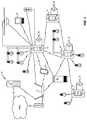
- FIG. 1is a diagram illustrating a lighting network according to one embodiment of the present disclosure.
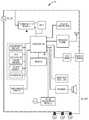
- FIG. 2is a functional schematic illustrating a lighting wall controller according to one embodiment of the present disclosure.
- FIG. 3is a functional schematic illustrating a lighting wall controller according to one embodiment of the present disclosure.
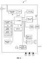
- FIG. 4is a functional schematic illustrating a lighting wall controller according to one embodiment of the present disclosure.
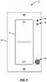
- FIG. 5is a diagram of a user interface for a lighting wall controller according to one embodiment of the present disclosure.
- FIG. 6is a diagram of a user interface for a lighting wall controller according to one embodiment of the present disclosure.
- FIG. 7is a diagram of a user interface of a lighting wall controller according to one embodiment of the present disclosure.
- FIG. 8is a diagram of a user interface of a lighting wall controller according to one embodiment of the present disclosure.
- FIG. 9is a call-flow diagram illustrating communication between a lighting wall controller and a remote device according to one embodiment of the present disclosure.
- FIG. 10is a call-flow diagram illustrating communication between a lighting wall controller and a remote device according to one embodiment of the present disclosure.
- FIG. 11is a flow diagram illustrating a method of processing one or more voice commands according to one embodiment of the present disclosure.
- a “dumb” light or deviceis one that is simply controlled by adjusting or cutting of the power to the device, e.g. by a conventional light switch or TRIAC dimmer.
- a “smart” light or deviceis a device that includes decision making capability such that it can respond to signals, commands, feedback and/or information from sensors or other devices to adjust its operation.
- FIG. 1shows a lighting network 10 according to one embodiment of the present disclosure.
- the lighting network 10includes a number of light bulbs 12 (which, while not shown as such, may also be lighting fixtures without departing from the principles of the present disclosure), a number of lighting wall controls 14 , a router 16 , a gateway 18 , a voice control appliance 20 , a voice control server 22 , and a connected device 24 , such as a smartphone, tablet, computer.
- Each one of these devicesis connected to one another, either directly or via an intermediate device.
- These connectionsare illustrated in FIG. 1 as lines located between the devices, and may represent wired or wireless connections in any number of different communications technologies and/or protocols.
- each one of the lighting wall controls 14may include multiple communication interfaces as discussed below in order to communicate with the light bulbs 12 using a first communication technology and/or protocol, communicate with the smartphone 24 using a second communication technology and/or protocol, and communicate with the voice control server 22 using a third communication technology and/or protocol.
- the light bulbs 12 , the lighting wall controls 14 , the router 16 , the voice control appliance 20 , the voice control server 22 , and the smartphone 24may form a local-area network (LAN). Communications between these devices may occur directly or through one or more intermediate devices such as the router 16 , which may facilitate communications between all of the devices.
- the gateway 18may connect the LAN to a wide-area network (WAN), such as the Internet.
- WANwide-area network
- the voice control server 22may connect to the devices in the lighting network 10 via the LAN. In other embodiments, the voice control server 22 connects to the devices in the lighting network via the WAN.
- the light bulbs 12are configured to receive power, for example, from an alternating current (AC) line source along with one or more control signals and provide a light output based thereon.
- One or more of the light bulbs 12may be “dumb” bulbs that are conventionally controlled, for example by an AC input signal AC_IN. These light bulbs 12 generally provide a light output that is proportional to an average amount of energy provided by the AC input signal AC_IN (e.g., via a triode for alternating current (TRIAC) dimmer), and do not include a means for communicating with other devices.
- TRIACtriode for alternating current
- Other light bulbs 12may be “smart” bulbs equipped with electronics to provide decision making capabilities and communications circuitry such that they are capable of receiving data from other devices such as one or more of the lighting wall controls 14 and adjusting the light output thereof based on the commands. In some embodiments, these “smart” light bulbs 12 may also be controlled by conventional means as discussed above.
- Each one of the lighting wall controls 14is configured to receive user input and power, for example, from an AC line source, and control a light output from one or more of the light bulbs 12 in response thereto.
- the lighting wall controls 14may do so by providing a user interface, which may be mechanical or software based (e.g., a touchscreen).
- a user interfacewhich may be mechanical or software based (e.g., a touchscreen).
- the lighting wall controls 14may provide the control signals thereto via a wired communications interface or a wireless communications interface.
- the wired control signalsmay be conventional alternating current (AC) dimmer signals (e.g., as provided by a dimmer switch such as a TRIAC dimmer), commands sent via an AC line interface (e.g., by modulating or otherwise transmitting data over the AC line), and/or Ethernet control signals.
- the wireless control signalsmay be Bluetooth, Zigbee, Thread, and/or Z-Wave control signals. In short, any type of wired or wireless control signals may be used to control a light output of the light bulbs 12 , and the type of control signals used may be dependent on the individual light bulbs 12 themselves as discussed above.
- each one of the lighting wall controls 14may communicate among themselves in order to synchronize tasks, share sensor data, coordinate listening for or responding to voice commands from a user, or the like.
- the lighting wall controls 14form a mesh network or a light mesh network in order to communicate with one another. Accordingly, the lighting wall controls 14 may relay commands between one another, allowing voice commands or user input provided at one of the lighting wall controls 14 to execute one or more actions on a different lighting wall control 14 .
- a voice command from a usermay indicate that the user wishes to dim the lights in a particular location, such as the master bedroom. If the voice command is not received by a lighting wall control 14 located in the master bedroom, the lighting wall control 14 may relay this command to the appropriate lighting wall control 14 , thereby allowing for the execution of the command.
- each one of the lighting wall controls 14may be associated with a particular location in a space.
- a lighting wall control 14may be associated with a master bedroom, a kitchen, a conference room, or the like. These locations, which may be provided by a user, determined automatically, or some combination thereof, may allow a user to provide voice commands that are spatially oriented such as the example given above where a user wishes to dim the lights in a master bedroom. Such a voice command will be communicated as necessary to the appropriate lighting wall controller 14 in order to execute the command. Associating the lighting wall controls 14 with locations may be especially important when the light bulbs 12 connected thereto are conventionally controlled, since the lighting wall control 14 is then the exclusive control point for the light output of these conventionally controlled light bulbs 12 .
- intervening lighting wall controllers 14may be bypassed such that the lighting wall controller 14 receiving a voice command may adjust the light output of the light bulbs 12 regardless of whether it is physically attached to them or located in the same room.
- the light bulbs 12themselves may be associated with a particular location in order to effectuate such behavior.
- the lighting wall controllers 14may control other “smart” devices in addition to the light bulbs 12 .
- the lighting wall controllers 14may directly or indirectly provide commands to door locks, thermostats, media controllers, connected power outlets, and the like based on voice commands from a user as described in detail below.
- the lighting wall controls 14act as a gateway for the light bulbs 12 , connecting them to the lighting network 10 .
- a separate lighting gatewayis provided through which the light bulbs 12 and the lighting wall controls 14 connect to other devices in the lighting network 10 .
- the lighting wall controls 14may have a reduced number of communication interfaces in order to simplify the design thereof.
- the control signals provided from the lighting wall controls 14 to the light bulbs 12may control any number of different parameters of the light provided therefrom.
- the control signals from the lighting wall controls 14may cause the light bulbs 12 to change an intensity of a light provided therefrom, a color of the light provided therefrom, a color temperature of the light provided therefrom, a color rendering index of the light provided therefrom, or any other desired parameter.
- Each of the lighting wall controls 14may control different groups of light bulbs 12 throughout the lighting network 10 . These groups of light bulbs 12 may be controlled via different communication interfaces as shown in FIG. 1 .
- the lighting wall controls 14may control the light output of a first group of light bulbs 12 via an AC interface, providing AC dimming signals thereto. Accordingly, the lighting wall controls 14 may be connected to the first group of light bulbs 12 via an AC line.
- the lighting wall controls 14may control the light output of a second group of light bulbs 12 via a wireless interface such as those discussed above. Accordingly, the lighting wall controls 14 do not have to be connected to the second group of light bulbs 12 directly.
- the lighting wall controls 14may operate the first group of light bulbs 12 and the second group of light bulbs 12 in a dependent (i.e., synchronous) or independent manner. That is, the lighting wall controls 14 may ensure that the light output from the first group of light bulbs 12 substantially matches that of the second group of light bulbs 12 , or may operate the light bulbs 12 such that the light output from the first group of light bulbs 12 is different from that of the second group of light bulbs 12 . In this way, the lighting wall controls 14 may “bridge” the control of multiple groups of light bulbs 12 in the lighting network 10 , each of which may be operate via a different communications interface in order to provide seamless control of light bulbs 12 throughout a space.
- lighting wall controls 14are shown coupled to separate light bulbs 12 in the lighting network 10 , the light bulbs 12 controlled by each one of the lighting wall controls 14 may overlap in some embodiments.
- lighting wall controls 14 in the lighting network 10may receive user input or voice commands from users which require execution of actions on other lighting wall controls 14 . This may occur, for example, when changes to a light output of light bulbs 12 or group of light bulbs 12 exclusively controlled by a particular lighting wall control 14 are requested by a user from a different lighting wall controller 14 or another device. This information may be passed to the appropriate lighting wall control 14 as necessary to execute these actions as discussed above.
- the lighting wall controls 14may receive commands from the connected device 24 such as a smartphone via a wired or wireless interface.
- the connected device 24may be any suitable device such as a tablet, a smart watch, a dedicated remote control, or the like.
- these commandsmay traverse one or more intermediate devices in the lighting network 10 before reaching one or more of the lighting wall controls 14 .
- one or more of the lighting wall controls 14may provide control signals to the light bulbs 12 in order to change a light output thereof.
- the lighting wall controls 14may receive commands from the voice control appliance 20 via a wired or wireless interface.
- the voice control appliance 20is a standalone device for responding to voice commands from a user. Commands may be generated by the voice control appliance 20 in response to voice input from a user. In generating the commands, the voice control appliance 20 may interact with the voice control server 22 .
- the voice control appliance 20 and/or voice control server 22may be configured to determine actions to take based on the voice commands from the user and relay these commands back to a requesting device.
- the computational complexity associated with natural language processingmay necessitate the use of the voice control server 22 in some situations, since it may not be feasible to perform these computations on other devices in the lighting network 10 that may have limited processing power and/or stringent efficiency requirements.
- While the voice control appliance 20may provide a convenient way to interact with one or more devices, a lighting network 10 may require several of them in order to adequately listen for voice commands within a given space. Since the voice control appliance 20 is a separate device dedicated only to that task, it may be expensive or inconvenient for a user to place a number of these throughout a space to provide the desired level of coverage. Generally, these voice control appliances 20 recognize voice commands from a user in a relatively limited area. Accordingly, a substantial number of these devices must be placed strategically throughout a space in order to provide the desired functionality throughout the space. Further, these voice control appliances often require access to a power outlet, which may be problematic and/or produce unsightly results.
- Lighting wall controls 14such as the one shown in FIG. 1 may be located in every room of a space, and in some cases in more than one place in a room. Further, these lighting wall controls 14 have access to power and are discreet in their appearance when compared to a dedicated device for which a user must find an appropriate spot. Finally, the placement of most lighting wall controllers 14 provides unrestricted access to sound waves in the surrounding area, and thus will be easily able to detect voice commands from a user. Accordingly, in order to provide voice control throughout the entirety of a space voice control or “virtual assistant” functionality is provided in the lighting wall controls 14 as discussed below.
- FIG. 2shows details of a lighting wall control 14 according to one embodiment of the present disclosure.
- the lighting wall control 14includes processing circuitry 26 , a memory 28 , a user interface 30 , communications circuitry 32 , sensor circuitry 34 , and power management circuitry 36 .
- the processing circuitry 26is configured to execute instructions stored in the memory 28 in order to provide the primary intelligence of the lighting wall control 14 .
- the memory 28includes a voice processing module 38 , which is a set of instructions stored in the memory 28 configured to allow the lighting wall control 14 to process voice commands as discussed below.
- additional modulessuch as a fault detection module for detecting failures within the lighting wall control 14 , a diagnostic module for diagnosing said errors, and a protection module for security or other purposes may be provided as instructions stored in the memory 28 or discrete circuitry in the lighting wall control 14 to increase the robustness of the device.
- the user interface 30allows a user to interact with the lighting wall control 14 , and may provide several ways to do so.
- the user interface 30may include a switch SW, which may be mechanical or any other type of switch, a capacitive or otherwise touch sensitive interface TCH, a display DSP, or the like.
- the user interface 30may include a touchless interface (not shown), such as a three-dimensional gesture sensor, which may be provided using various sensors such as an image sensor.
- the displaymay be as simple or complex as desired.
- the displaymay be an indicator LED, multiple indicator LEDs, an LED array, a full display such as a liquid crystal display (LCD), or any combination thereof.
- LCDliquid crystal display
- the user interface 30may include a microphone MIC and a speaker SPK.
- the microphone MICmay include multiple microphones, which may be provided in an array in order to more accurately recognize voice commands from a user.
- the speaker SPKmay include multiple speakers in order to provide better sound, or may connect to one or more remote speakers in order to provide audible feedback to a user.
- the communications circuitry 32may include multiple communications interfaces 40 , each of which may utilize a different communications technology and/or protocol to communicate with other devices in the lighting network 10 .
- a first communication interface 40 Amay be a WiFi communications interface
- a second communication interface 40 Bmay be a Bluetooth communications interface
- an n th communication interface 40 Nmay be a IEEE 802.15 communications interface.
- the communications circuitry 32may include any number of different communications interfaces 40 in order to communicate with a variety of devices in the lighting network 10 .
- the lighting wall control 14may include a limited number of communications interfaces 40 , and may communicate to other devices in the lighting network 10 via a separate lighting gateway.
- the sensor circuitry 34may include any number of sensors to allow the lighting wall control 14 to receive input from the surrounding environment.
- the sensor circuitry 34may include an ambient light sensor ALS, an occupancy sensor OCC, and an image sensor IMG.
- the ambient light sensor ALSmay provide a measurement of the ambient light in the surrounding environment to the lighting wall control 14 , which it may use to control a light output from one or more of the light bulbs 12 .
- the occupancy sensor OCCmay indicate whether or not the environment surrounding the lighting wall control 14 is occupied by a person, which may be used by the lighting wall control 14 to turn on and off the light bulbs 12 .
- the image sensor IMGmay be used to detect ambient light, occupancy, motion, and other light characteristics of the light bulbs 12 .
- any of these measurementsmay be used to adjust a light output of the light bulbs 12 in a desired fashion.
- any number of additional sensormay be added to the sensor circuitry 34 (e.g., temperature sensors, barometric pressure sensors, accelerometers, or the like) in order to allow the lighting wall control 14 to collect additional information about the surrounding environment.
- the power management circuitry 36may be configured to receive an AC input signal AC_IN, for example, an AC line voltage, and provide an AC output signal AC_OUT to one or more of the light bulbs 12 . In doing so, the lighting wall control 14 may dim or otherwise alter the light output of the light bulbs.
- the power management circuitry 36includes an AC dimmer (not shown).
- the power management circuitry 36includes power converter circuitry such as AC to direct current (DC) converter circuitry, power factor correction circuitry, rectifier circuitry, or the like (not shown).
- the power management circuitry 36may be configured to be wired in a three-way, four-way, or multiple-way AC circuit.
- the power management circuitry 36may cooperate with the processing circuitry 26 in order to properly respond to AC signals received from other switches in the multiple-way configuration and to properly provide AC signals to other switches in the multiple-way configuration in order for all of the switches in the circuit to properly function.
- multiple switches in the circuitare lighting wall controls 14 including intelligence such as the one discussed herein, the lighting wall controls 14 may effectuate the multiple-way behavior by communicating in a wired or wireless manner.
- the lighting wall control 14may manipulate an AC output thereof in order to effectuate the multiple-way behavior.
- the lighting wall control 14may require pass-through or constant AC power to provide all of the functionality thereof, and such considerations must therefore be taken when including the lighting wall control in a multiple-way circuit.
- the power management circuitry 36may also be configured to receive DC input signals, condition or otherwise alter these signals as desired, and provide one or more output signals to the light bulbs 12 to control the light output thereof.
- the power management circuitry 36may include a battery to provide power in the event of a power outage, or to ensure storage of settings or otherwise operate one or more aspects of the lighting wall control 14 when line power is not available.
- FIG. 3shows a lighting wall control 14 according to an additional embodiment of the present disclosure.
- the lighting wall control 14 shown in FIG. 3is substantially similar to that shown in FIG. 2 , but further includes dedicated voice processing circuitry 42 therein.
- the dedicated voice processing circuitry 42may be optimized for recognizing human speech.
- the dedicated voice processing circuitry 42is configured to transcribe spoken words into text, data, or any appropriate form, which may then be parsed to determine one or more actions to be taken based thereon.
- the dedicated voice processing circuitry 42may be optimized to listen for a “trigger phrase”, which may indicate that a person is providing a voice command to the lighting wall control 14 .
- Listening for a trigger phrasemay prevent the lighting wall control 14 from recording all spoken words in the surrounding environment in order to increase the privacy of users.
- the voice processing circuitry 42may be provided as a specialized application-specific integrated circuit (ASIC), a field-programmable gate array (FPGA), or the like.
- ASICapplication-specific integrated circuit
- FPGAfield-programmable gate array
- Providing dedicated voice processing circuitry 42 in the lighting wall control 14may free up valuable processing power in the processing circuitry 26 for performing other tasks.
- FIG. 4shows a lighting wall controller 14 according to an additional embodiment of the present disclosure.
- the lighting wall controller 14includes processing circuitry, which is configured to execute instructions stored in a memory to provide the central intelligence of the lighting wall controller 14 .
- a power supply modulealong with a battery connected thereto, receives an AC input signal AC_IN and provides power to the processing circuitry, which may be distributed to other portions of the device.
- Fault and protection circuitryincreases the robustness of the lighting wall controller by detecting faults and responding thereto.
- Wireless communications circuitryallows the lighting wall controller to communicate with other devices in the lighting network 10 .
- Gate drive circuitrycontrols a power device, which is in line with the AC line voltage provided to the light bulbs 12 in order to control the light output thereof in a conventional manner as discussed above.
- the power devicemay be a transistor device or any other suitable device for controlling the amount of energy delivered to the light bulbs 12 .
- An indicatorsuch as an LED or an LCD is provided, and may be used to provide feedback to a user as discussed above.
- a speaker and associated circuitrymay similarly be used to provide audible feedback to a user.
- a voice recognition modulealong with a microphone attached thereto allows the lighting wall control 14 to receive and respond to voice commands.
- a mechanical switchallows a user to cut power to the light bulbs 12 when desired.
- a number of sensorsincluding an occupancy sensor, an ambient light sensor, an image sensor, a touch sensor (which may be a capacitive touch sensor), and a three-dimensional gesture sensor allow the lighting wall control 14 to receive input from the surrounding environment.
- the processing circuitryis coupled to each one of the fault and protection circuitry, the wireless communications circuitry, the gate drive circuitry, the indicator, the speaker, the voice recognition module, the mechanical switch, and the sensors. Accordingly, the processing circuitry may receive input from these portions of the device or provide commands thereto to direct the activity of the lighting wall control 14 .
- the processing circuitrymay be a microcontroller unit or the like.
- FIG. 5shows a user interface 30 for a lighting wall control 14 according to one embodiment of the present disclosure.
- the user interface 30includes a touch panel 44 , which may be mechanical, capacitive, or otherwise touch sensitive. Further, while referred to as a “touch” panel, the touch panel 44 may respond to non-touch gestures such as those performed by a user in the space surrounding the lighting wall control 14 .
- the touch panel 44may control the intensity of light provided by light bulbs 12 controlled by the lighting wall controller based on input from a user.
- a faceplate 46is provided around the touch panel 44 .
- the faceplate 46may include a first opening 48 , a second opening 50 , and a third opening 52 .
- the first opening 48may provide the microphone MIC access to the surrounding environment so that voice commands from a user may be detected.
- the second opening 50may provide optical access to the surrounding environment for one or more of the ambient light sensor ALS, the occupancy sensor OCC, and the image sensor IMG. Additional openings may be provided in embodiments in which more than one of these sensors is provided.
- the third opening 52may provide the speaker SPK access to the surrounding environment so that audible feedback and other sounds may be provided from the lighting wall control 14 .
- FIG. 6shows a user interface 30 for a lighting wall control 14 according to an additional embodiment of the present disclosure.
- the user interface 30is substantially similar to that shown in FIG. 5 , except that the touch panel 44 shown in FIG. 5 is replaced with a touchscreen 54 .
- the touchscreenmay display information about the light bulbs 12 controlled by the lighting wall control 14 as well as any other devices in the lighting network 10 .
- the touchscreen 54may display the current occupancy status and the current brightness setting of the light bulbs 12 as shown in FIG. 6 .
- Controls that are often usedmay be displayed in a prominent manner to allow a user to easily and intuitively control a light output of the light bulbs 12 connected to the lighting wall control 14 .
- An indicatormay be provided that the lighting wall control 14 is currently ready for voice commands from a user.
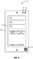
- FIG. 7shows the user interface 30 illustrated in FIG. 6 after a voice command has been detected by a user.
- the touchscreen 54may indicate the command that was detected and indicate an action that is currently being executed in response thereto.
- a progress indicatormay be provided.
- feedbackmay be solicited to refine the accuracy of voice recognition of the lighting wall control 14 .
- a prompt on the screenmay ask whether the detected voice command was accurately transcribed, and whether the resulting action was the intended consequence of the detected voice command.
- the lighting wall control 14 and/or a backend device used for responding to the voice commandsmay alter the transcription and/or response to the voice commands in order to better respond to voice commands over time.
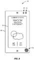
- FIG. 8shows the user interface 30 illustrated in FIG. 6 after a different type of voice command has been detected by a user. While voice commands may be used to instruct the lighting wall control 14 to provide control signals to one or more other devices, they may also be used to request information from the lighting wall control 14 , which must then be displayed or otherwise communicated to the user. For example, a user may ask for the weather forecast, which may then be displayed as shown in FIG. 8 . Other types of information may be requested and displayed as well.
- audible feedbackmay be provided by the user in addition to displaying the information on the touchscreen 54 or other user interface. Such audible feedback may include computer generated speech responding to the request from the user.
- FIG. 9is a call flow diagram illustrating communications between a lighting wall control 14 and a remote device 56 in order to execute one or more actions based on voice commands from a user according to one embodiment of the present disclosure.
- a voice commandis received from a user ( 100 ).
- the lighting wall control 14may constantly listen for voice commands and/or trigger phrases via the microphone MIC as discussed above.
- the voice commandmay then be transcribed into text, data representative of the voice command, or any appropriate form ( 102 ).
- the voice transcriptionmay be accomplished via the processing circuitry 26 or the dedicated voice processing circuitry 42 .
- the transcribed voice commandis then sent to a remote device 56 ( 104 ), which may be the voice control appliance 20 , the voice control server 22 , or any other device, through one or more intermediate devices (e.g., the router 16 , the gateway 18 , or any other device).
- the remote device 56determines any necessary actions to be taken based on the transcribed voice command ( 106 ). For example, the remote device 56 may use natural language processing along with machine learning algorithms to determine the intent of the voice command and how to respond. These actions are then sent back to the lighting wall control 14 ( 108 ), where they are executed thereby ( 110 ).
- the actionsmay include changing a light output of one or more of the light bulbs 12 , displaying information, controlling one or more other devices in the lighting network 10 , or any other task.
- a usermay request the lighting wall control 14 to “Turn on the lights,” to “Set the brightness of the lights in conference room 1 to 80%,” or to “Turn on the projector.”
- the lighting wall control 14along with the remote device will determine the necessary actions to be taken based on these requests.
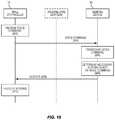
- FIG. 10is a call flow diagram illustrating communications between a lighting wall control 14 and a remote device 56 in order to execute one or more actions based on voice commands from a user according to an additional embodiment of the present disclosure.
- a voice commandis received from a user ( 200 ).
- the voice commandis then sent to a remote device 56 ( 202 ).
- the remote device 56may be the voice control appliance 20 , the voice control server 22 , or any other device, and communication with the remote device may occur between one or more intermediate devices.
- Sending the voice command to the remote device 56may include performing analog-to-digital conversion of the voice command from the user and sending a digital version thereof to the remote device 56 .
- compressionmay be applied to the digital version of the voice command in order to reduce the required bandwidth of communication between the lighting wall control 14 and the remote device 56 .
- the remote device 56may then transcribe the voice command ( 204 ) using dedicated hardware or software as discussed above, and may determine any necessary actions to be taken based on the transcribed voice command ( 206 ) as discussed above. These actions are then sent back to the lighting wall control 14 ( 208 ), where they are executed thereby ( 210 ).
- FIG. 11is a flow diagram illustrating a method for responding to voice commands from the lighting wall control 14 according to one embodiment of the present disclosure.
- a voice commandis received ( 300 ).
- the voice commandis then transcribed into text, data representative of the voice command, or any appropriate form ( 302 ) for further processing.
- Necessary actions based on the transcribed voice commandare then determined ( 304 ), and executed ( 306 ) by the lighting wall control 14 .
- the transcription and determination of actions based on the transcribed voice commandare performed locally on the lighting wall control 14 in the embodiment shown in FIG. 11 . This may be enabled by the dedicated voice processing circuitry 42 discussed above.
- FIGS. 9-11illustrate different ways that the lighting wall control 14 could cooperate with a remote device such as the voice control appliance 20 and a voice control server 22 in order to respond to voice commands from a user.
- theyillustrate different ways to distribute the transcription and processing of voice commands from a user to accomplish a desired task based thereon.
- the above approachesillustrate that the voice processing module 38 and/or the voice processing circuitry 42 in the lighting wall control 14 may perform several different levels of voice processing based on the embodiment.
- the voice processing performed by the voice processing module 38 and/or the voice processing circuitry 42may be a simple analog-to-digital conversion, or may involve more intensive processing such as voice-to-text transcription.
- the voice processing module 38 and/or the voice processing circuitry 42may work alongside the processing circuitry 26 in order to perform even more intensive processing such as natural language processing and the like in order to determine a desired action to be performed based on the voice commands.
- voice processingused throughout the present application may indicate many different levels of intensity of processing of the voice commands.
- a lighting wall controllercould parse and respond to voice commands from a user, all of which are contemplated herein. Regardless of the details of how it is accomplished, providing hardware and accompanying software for detecting voice commands in a lighting wall control 14 allows voice command (i.e., “virtual assistant”) functionality to be distributed throughout a space without the need for a multitude of dedicated hardware that may be expensive or unsightly. That is, due to the fact that lighting wall controls 14 are already integrated into a power infrastructure and distributed spatially throughout a home, these lighting wall controls 14 offer significant benefits for providing an interface for voice control over dedicated hardware.
- voice commandi.e., “virtual assistant”
- the wall controlleraccording to principles of the present disclosure need not control lights (or at least not in the conventional fashion) even though it replaces a conventional light switch or is mounted where a conventional light switch would typically be located.
- the wall controllerscan network with each other in various network structures, including with other devices, lights and/or sensors. All such improvements and modifications are considered within the scope of the concepts disclosed herein and the claims that follow.
Landscapes
- Engineering & Computer Science (AREA)
- Computational Linguistics (AREA)
- Health & Medical Sciences (AREA)
- Audiology, Speech & Language Pathology (AREA)
- Human Computer Interaction (AREA)
- Physics & Mathematics (AREA)
- Acoustics & Sound (AREA)
- Multimedia (AREA)
- Computer Networks & Wireless Communication (AREA)
- Circuit Arrangement For Electric Light Sources In General (AREA)
Abstract
Description
Claims (24)
Priority Applications (1)
| Application Number | Priority Date | Filing Date | Title |
|---|---|---|---|
| US15/714,290US10595380B2 (en) | 2016-09-27 | 2017-09-25 | Lighting wall control with virtual assistant |
Applications Claiming Priority (2)
| Application Number | Priority Date | Filing Date | Title |
|---|---|---|---|
| US201662400525P | 2016-09-27 | 2016-09-27 | |
| US15/714,290US10595380B2 (en) | 2016-09-27 | 2017-09-25 | Lighting wall control with virtual assistant |
Publications (2)
| Publication Number | Publication Date |
|---|---|
| US20180092189A1 US20180092189A1 (en) | 2018-03-29 |
| US10595380B2true US10595380B2 (en) | 2020-03-17 |
Family
ID=61685975
Family Applications (1)
| Application Number | Title | Priority Date | Filing Date |
|---|---|---|---|
| US15/714,290ActiveUS10595380B2 (en) | 2016-09-27 | 2017-09-25 | Lighting wall control with virtual assistant |
Country Status (1)
| Country | Link |
|---|---|
| US (1) | US10595380B2 (en) |
Families Citing this family (11)
| Publication number | Priority date | Publication date | Assignee | Title |
|---|---|---|---|---|
| US10327117B2 (en)* | 2017-02-08 | 2019-06-18 | CliniCloud Inc. | Virtual mesh network for medical voice command devices |
| EP3622784B1 (en)* | 2017-05-08 | 2020-11-11 | Signify Holding B.V. | Voice control |
| US10826857B2 (en)* | 2017-10-20 | 2020-11-03 | Sap Se | Message processing for cloud computing applications |
| US10531540B2 (en)* | 2018-03-22 | 2020-01-07 | Cheng Uei Precision Industry Co., Ltd. | Intelligent lamp holder and usage method applied therein |
| US10811370B2 (en) | 2018-04-24 | 2020-10-20 | Cree, Inc. | Packaged electronic circuits having moisture protection encapsulation and methods of forming same |
| US20210125613A1 (en)* | 2018-05-18 | 2021-04-29 | Schneider Electric Asia Pte Ltd | A relay device |
| CN112166408B (en)* | 2018-05-25 | 2024-06-11 | 三星电子株式会社 | Method and apparatus for providing intelligent response |
| CN108990215B (en)* | 2018-08-28 | 2024-04-30 | 四川蓝景光电技术有限责任公司 | Adjustable LED driving power supply and LED dimming method |
| EP3878243A1 (en)* | 2018-11-05 | 2021-09-15 | Signify Holding B.V. | Adapting a lighting control interface based on an analysis of conversational input |
| DE102018129687A1 (en)* | 2018-11-26 | 2020-05-28 | Insta Gmbh | Control unit for home automation |
| US12349257B2 (en)* | 2021-01-25 | 2025-07-01 | Signify Holding B.V. | Selecting a set of lighting devices based on an identifier of an audio and/or video signal source |
Citations (263)
| Publication number | Priority date | Publication date | Assignee | Title |
|---|---|---|---|---|
| USD259514S (en) | 1978-09-01 | 1981-06-09 | Welch James D | Decorative lamp |
| USD317363S (en) | 1988-07-29 | 1991-06-04 | Welch James D | Decorative lamp |
| US5079680A (en) | 1991-06-07 | 1992-01-07 | Reflector Hardware Corporation | Undershelf task light fixture |
| USD344361S (en) | 1992-04-03 | 1994-02-15 | Reflector Hardware Corporation | Desk lamp |
| USD349582S (en) | 1992-04-03 | 1994-08-09 | Reflector Hardware Corporation | Tiltable desk lamp |
| US5471119A (en) | 1994-06-08 | 1995-11-28 | Mti International, Inc. | Distributed control system for lighting with intelligent electronic ballasts |
| USD373438S (en) | 1994-10-11 | 1996-09-03 | Light Corporation | Desk lamp |
| JPH11345690A (en) | 1998-06-03 | 1999-12-14 | Toshiba Lighting & Technology Corp | Lighting system |
| US6100643A (en) | 1980-08-14 | 2000-08-08 | Nilssen; Ole K. | Modular electronic lighting system |
| US6118230A (en) | 1998-01-30 | 2000-09-12 | Hewlett-Packard Company | Lighting control system including server for receiving and processing lighting control requests |
| US6137408A (en) | 1998-06-09 | 2000-10-24 | Keyence Corporation | Controller for plural area sensors |
| US6160359A (en) | 1998-01-30 | 2000-12-12 | Hewlett-Packard Company | Apparatus for communicating with a remote computer to control an assigned lighting load |
| US6166496A (en) | 1997-08-26 | 2000-12-26 | Color Kinetics Incorporated | Lighting entertainment system |
| US6211626B1 (en) | 1997-08-26 | 2001-04-03 | Color Kinetics, Incorporated | Illumination components |
| WO2001026327A2 (en) | 1999-10-06 | 2001-04-12 | Sensoria Corporation | Apparatus for sensor networking |
| WO2001026068A1 (en) | 1999-10-06 | 2001-04-12 | Sensoria Corporation | Wireless networked sensors |
| WO2001026335A2 (en) | 1999-10-06 | 2001-04-12 | Sensoria Corporation | Distributed signal processing in a network |
| JP2001155870A (en) | 1999-11-29 | 2001-06-08 | Matsushita Electric Works Ltd | Lighting equipment |
| US20020047646A1 (en) | 1997-08-26 | 2002-04-25 | Ihor Lys | Lighting entertainment system |
| WO2002039242A1 (en) | 2000-10-31 | 2002-05-16 | Millennial Net, Inc. | Networked processing system with optimized power efficiency |
| CA2511368A1 (en) | 2000-11-17 | 2002-05-23 | Eimar M. Boesjes | Distributed wireless online access system |
| WO2002041604A2 (en) | 2000-11-17 | 2002-05-23 | Boesjes Eimar M | Distributed wireless online access system |
| US6437692B1 (en) | 1998-06-22 | 2002-08-20 | Statsignal Systems, Inc. | System and method for monitoring and controlling remote devices |
| US6441558B1 (en) | 2000-12-07 | 2002-08-27 | Koninklijke Philips Electronics N.V. | White LED luminary light control system |
| US20020195975A1 (en) | 2001-03-13 | 2002-12-26 | Schanberger Eric K. | Systems and methods for synchronizing lighting effects |
| US6528954B1 (en) | 1997-08-26 | 2003-03-04 | Color Kinetics Incorporated | Smart light bulb |
| WO2003047175A1 (en) | 2001-11-28 | 2003-06-05 | Millennial Net | Etwork protocol for an ad hoc wireless network |
| JP2003178889A (en) | 2001-12-12 | 2003-06-27 | Mitsubishi Electric Corp | Lighting system |
| US20040001963A1 (en) | 2002-06-10 | 2004-01-01 | Oji Paper Co., Ltd. | Coated paper sheet |
| US20040002792A1 (en) | 2002-06-28 | 2004-01-01 | Encelium Technologies Inc. | Lighting energy management system and method |
| US20040051467A1 (en) | 2002-09-16 | 2004-03-18 | Gnanagiri Balasubramaniam | System for control of devices |
| US6735630B1 (en) | 1999-10-06 | 2004-05-11 | Sensoria Corporation | Method for collecting data using compact internetworked wireless integrated network sensors (WINS) |
| US20040193741A1 (en) | 1999-09-23 | 2004-09-30 | Pereira Jose P. | Priority circuit for content addressable memory |
| US20040232851A1 (en) | 2003-05-22 | 2004-11-25 | Roach Peter O. | Deriving power for a wireless network component from the power source of a fluorescent light |
| US6826607B1 (en) | 1999-10-06 | 2004-11-30 | Sensoria Corporation | Apparatus for internetworked hybrid wireless integrated network sensors (WINS) |
| US6832251B1 (en) | 1999-10-06 | 2004-12-14 | Sensoria Corporation | Method and apparatus for distributed signal processing among internetworked wireless integrated network sensors (WINS) |
| WO2004109966A2 (en) | 2003-06-05 | 2004-12-16 | Millennial Net | Protocol for configuring a wireless network |
| US6859831B1 (en) | 1999-10-06 | 2005-02-22 | Sensoria Corporation | Method and apparatus for internetworked wireless integrated network sensor (WINS) nodes |
| US20050127381A1 (en) | 2003-12-10 | 2005-06-16 | Pranciskus Vitta | White light emitting device and method |
| US6914893B2 (en) | 1998-06-22 | 2005-07-05 | Statsignal Ipc, Llc | System and method for monitoring and controlling remote devices |
| US6990394B2 (en) | 2002-12-24 | 2006-01-24 | Pasternak Barton A | Lighting control system and method |
| US20060022214A1 (en) | 2004-07-08 | 2006-02-02 | Color Kinetics, Incorporated | LED package methods and systems |
| US20060044152A1 (en) | 2002-09-04 | 2006-03-02 | Ling Wang | Master-slave oriented two-way rf wireless lighting control system |
| US7009348B2 (en) | 2002-06-03 | 2006-03-07 | Systel Development & Industries Ltd. | Multiple channel ballast and networkable topology and system including power line carrier applications |
| US7020701B1 (en) | 1999-10-06 | 2006-03-28 | Sensoria Corporation | Method for collecting and processing data using internetworked wireless integrated network sensors (WINS) |
| US20060066266A1 (en) | 2004-03-11 | 2006-03-30 | Li Lim Kevin L | System and method for producing white light using a combination of phosphor-converted with LEDs and non-phosphor-converted color LEDs |
| US20060076908A1 (en)* | 2004-09-10 | 2006-04-13 | Color Kinetics Incorporated | Lighting zone control methods and apparatus |
| US7031920B2 (en) | 2000-07-27 | 2006-04-18 | Color Kinetics Incorporated | Lighting control using speech recognition |
| KR20060050614A (en) | 2004-08-25 | 2006-05-19 | 도시바 라이텍쿠 가부시키가이샤 | Setting method of lighting system, setter, lighting device and lighting system |
| US20060125426A1 (en) | 2004-12-14 | 2006-06-15 | Dragan Veskovic | Distributed intelligence ballast system and extended lighting control protocol |
| US20060161270A1 (en)* | 2004-10-14 | 2006-07-20 | Lagotek Corporation | Distributed wireless home and commercial electrical automation systems |
| US7103511B2 (en) | 1998-10-14 | 2006-09-05 | Statsignal Ipc, Llc | Wireless communication networks for providing remote monitoring of devices |
| WO2006095316A1 (en) | 2005-03-11 | 2006-09-14 | Koninklijke Philips Electronics N.V. | Grouping wireless lighting nodes according to a building room layout |
| US7139562B2 (en) | 2002-09-27 | 2006-11-21 | Matsushita Electric Industrial Co., Ltd. | Remote control device |
| US20060262545A1 (en) | 2005-05-23 | 2006-11-23 | Color Kinetics Incorporated | Led-based light-generating modules for socket engagement, and methods of assembling, installing and removing same |
| WO2006130662A2 (en) | 2005-06-01 | 2006-12-07 | Millennial Net, Inc. | Communicating over a wireless network |
| US20070013557A1 (en) | 2005-07-15 | 2007-01-18 | Wang Sean X | Novel lighting apparatus for navigational aids |
| US20070040512A1 (en) | 2005-08-17 | 2007-02-22 | Tir Systems Ltd. | Digitally controlled luminaire system |
| US20070085700A1 (en) | 2005-09-12 | 2007-04-19 | Acuity Brands, Inc. | Light management system having networked intelligent luminaire managers with enhanced diagnostics capabilities |
| US20070126656A1 (en) | 2005-12-07 | 2007-06-07 | Industrial Technology Research Institute | Illumination brightness and color control system and method therefor |
| US20070132405A1 (en) | 2002-09-04 | 2007-06-14 | Hillis W D | General operating system |
| US20070189000A1 (en) | 2006-02-08 | 2007-08-16 | Konstantinos Papamichael | Method for preventing incorrect lighting adjustments in a daylight harvesting system |
| WO2007102097A1 (en) | 2006-03-07 | 2007-09-13 | Philips Intellectual Property & Standards Gmbh | Lighting system with lighting units using optical communication |
| US7288902B1 (en) | 2007-03-12 | 2007-10-30 | Cirrus Logic, Inc. | Color variations in a dimmable lighting device with stable color temperature light sources |
| US7305467B2 (en) | 2002-01-02 | 2007-12-04 | Borgia/Cummins, Llc | Autonomous tracking wireless imaging sensor network including an articulating sensor and automatically organizing network nodes |
| US20070291483A1 (en) | 2001-05-30 | 2007-12-20 | Color Kinetics Incorporated | Controlled lighting methods and apparatus |
| USD560006S1 (en) | 2007-06-09 | 2008-01-15 | Light Corporation | Reminder light |
| US7344279B2 (en) | 2003-12-11 | 2008-03-18 | Philips Solid-State Lighting Solutions, Inc. | Thermal management methods and apparatus for lighting devices |
| USD565771S1 (en) | 2007-06-09 | 2008-04-01 | Light Corporation | Gooseneck lamp |
| US20080088435A1 (en) | 2005-03-12 | 2008-04-17 | Lutron Electronics Co., Inc. | Handheld programmer for lighting control system |
| USD567431S1 (en) | 2007-06-09 | 2008-04-22 | Light Corporation | Desk lamp |
| US20080197790A1 (en) | 2002-12-11 | 2008-08-21 | Mangiaracina Anthony A | Lighting utilizing power over the ethernet |
| US20080218087A1 (en) | 2005-09-07 | 2008-09-11 | Koninklijke Philips Electronics, N.V. | Lighting Commissioning Device and Method |
| US7443113B2 (en) | 2003-12-02 | 2008-10-28 | Universal Lighting Technologies, Inc. | Software controlled electronic dimming ballast |
| US20080265799A1 (en) | 2007-04-20 | 2008-10-30 | Sibert W Olin | Illumination control network |
| USD582598S1 (en) | 2007-06-07 | 2008-12-09 | Light Corporation | Light assembly |
| WO2009011898A2 (en) | 2007-07-17 | 2009-01-22 | I/O Controls Corporation | Control network for led-based lighting system in a transit vehicle |
| US7484008B1 (en) | 1999-10-06 | 2009-01-27 | Borgia/Cummins, Llc | Apparatus for vehicle internetworks |
| US7482567B2 (en) | 2004-09-24 | 2009-01-27 | Koninklijke Philips Electronics N.V. | Optical feedback system with improved accuracy |
| USD586950S1 (en) | 2007-06-09 | 2009-02-17 | Light Corporation | Rail |
| USD587390S1 (en) | 2007-06-09 | 2009-02-24 | Light Corporation | Rail light |
| USD588064S1 (en) | 2007-06-09 | 2009-03-10 | Light Corporation | USB assembly |
| USD594576S1 (en) | 2008-02-29 | 2009-06-16 | Advanced Optoelectronic Technology Inc. | LED module |
| WO2009076492A1 (en) | 2007-12-13 | 2009-06-18 | Daniel John Julio | Lighting control architechture |
| US20090184616A1 (en) | 2007-10-10 | 2009-07-23 | Cree Led Lighting Solutions, Inc. | Lighting device and method of making |
| US20090212718A1 (en) | 2008-02-26 | 2009-08-27 | Panasonic Electric Works Co., Ltd. | Illumination control system |
| US7587289B1 (en) | 2007-02-13 | 2009-09-08 | American Megatrends, Inc. | Data cable powered sensor fixture |
| US20090231832A1 (en) | 2008-03-15 | 2009-09-17 | Arturas Zukauskas | Solid-state lamps with complete conversion in phosphors for rendering an enhanced number of colors |
| US20090230894A1 (en) | 2006-05-11 | 2009-09-17 | Koninklijke Philips Electronics N.V. | Lighting system with linked groups |
| US20090237011A1 (en) | 2008-03-20 | 2009-09-24 | Ashok Deepak Shah | Illumination Device and Fixture |
| US20090267540A1 (en) | 2008-04-14 | 2009-10-29 | Digital Lumens, Inc. | Modular Lighting Systems |
| US20090284169A1 (en) | 2008-05-16 | 2009-11-19 | Charles Bernard Valois | Systems and Methods for Communicating in a Lighting Network |
| WO2009145747A1 (en) | 2007-05-24 | 2009-12-03 | Face Bradbury R | Lighting fixture with low voltage transformer & self-powered switching system |
| US20090302994A1 (en) | 2008-06-10 | 2009-12-10 | Mellennial Net, Inc. | System and method for energy management |
| US20090305644A1 (en) | 2008-06-10 | 2009-12-10 | Millennial Net, Inc. | System and method for a wireless controller |
| US20090302996A1 (en) | 2008-06-10 | 2009-12-10 | Millennial Net, Inc. | System and method for a management server |
| WO2009151416A1 (en) | 2008-06-10 | 2009-12-17 | Millennial Net, Inc. | System and method for energy management |
| US20090315485A1 (en) | 2007-06-29 | 2009-12-24 | Orion Energy Systems, Inc. | Lighting fixture control systems and methods |
| US20090315668A1 (en) | 2008-06-19 | 2009-12-24 | Light Corporation | Wiring topology for a building with a wireless network |
| US7638743B2 (en) | 2007-06-29 | 2009-12-29 | Orion Energy Systems, Inc. | Method and system for controlling a lighting system |
| WO2009158514A1 (en) | 2008-06-26 | 2009-12-30 | Telelumen, LLC | Authoring, recording, and replication of lighting |
| US20100007289A1 (en) | 2008-04-28 | 2010-01-14 | Budike Jr Lothar E S | Multi configurable lighting and energy control system and modules |
| US7649456B2 (en) | 2007-01-26 | 2010-01-19 | Sony Ericsson Mobile Communications Ab | User interface for an electronic device used as a home controller |
| US20100013649A1 (en)* | 2006-06-20 | 2010-01-21 | Spira Joel S | Load control device having audible feedback |
| WO2010010493A2 (en) | 2008-07-21 | 2010-01-28 | Koninklijke Philips Electronics N.V. | Method of setting up a luminaire and luminaire to apply the method |
| JP2010050069A (en) | 2008-08-25 | 2010-03-04 | Panasonic Electric Works Co Ltd | Illumination control system |
| WO2010047971A2 (en) | 2008-10-24 | 2010-04-29 | Altair Engineering, Inc. | Light and light sensor |
| US20100134051A1 (en) | 2009-03-02 | 2010-06-03 | Adura Technologies, Inc. | Systems and methods for remotely controlling an electrical load |
| US20100150122A1 (en) | 2008-10-29 | 2010-06-17 | Berger Thomas R | Managing and monitoring emergency services sector resources |
| US20100203515A1 (en) | 2006-12-22 | 2010-08-12 | Rudolf Rigler | Detection of gene expression in cells by scanning fcs |
| JP2010198877A (en) | 2009-02-24 | 2010-09-09 | Panasonic Electric Works Co Ltd | Lighting control system |
| WO2010122457A2 (en) | 2009-04-24 | 2010-10-28 | Koninklijke Philips Electronics N.V. | System for controlling a plurality of light sources |
| US20100270935A1 (en) | 2009-04-24 | 2010-10-28 | Toshiba Lighting & Technology Corporation | Light-emitting device and illumination apparatus |
| US20100295473A1 (en) | 2008-04-14 | 2010-11-25 | Digital Lumens, Inc. | Power Management Unit with Sensor Logging |
| US20100301774A1 (en) | 2008-04-14 | 2010-12-02 | Digital Lumens, Inc. | Power Management Unit with Automatic Output Configuration |
| US20100301770A1 (en) | 2008-04-14 | 2010-12-02 | Digital Lumens, Inc. | Power Management Unit with Lifetime Prediction |
| US20100301773A1 (en) | 2009-04-14 | 2010-12-02 | Digital Lumens, Inc. | Fixture with Individual Light Module Dimming |
| KR20110001782A (en) | 2009-06-30 | 2011-01-06 | 엘지이노텍 주식회사 | Lighting control system |
| US7868562B2 (en) | 2006-12-11 | 2011-01-11 | Koninklijke Philips Electronics N.V. | Luminaire control system and method |
| US20110025469A1 (en) | 2008-04-18 | 2011-02-03 | Koninklijke Philips Electronics N.V. | Method of commissioning a device arrangement |
| US20110031897A1 (en) | 2009-08-10 | 2011-02-10 | Redwood Systems, Inc. | Lighting systems and methods of auto-commissioning |
| US20110057581A1 (en) | 2009-09-05 | 2011-03-10 | Enlighted, Inc. | Floor Plan Deduction Using Lighting Control and Sensing |
| US20110080120A1 (en) | 2008-06-11 | 2011-04-07 | Koninklijke Philips Electronics N.V. | wireless, remotely controlled, device selection system and method |
| US7924927B1 (en) | 2005-03-21 | 2011-04-12 | Boesjes Eimar M | Distributed functionality in a wireless communications network |
| US7924174B1 (en) | 2006-05-26 | 2011-04-12 | Cooper Technologies Company | System for controlling a lighting level of a lamp in a multi-zone environment |
| US20110095687A1 (en) | 2009-10-25 | 2011-04-28 | Greenwave Reality, Inc. | Modular Networked Light Bulb |
| US20110101871A1 (en) | 2008-03-12 | 2011-05-05 | Koninklijke Philips Electronics N.V. | Configuration of a luminaire system |
| US20110115407A1 (en) | 2009-11-13 | 2011-05-19 | Polar Semiconductor, Inc. | Simplified control of color temperature for general purpose lighting |
| US20110137757A1 (en) | 2008-06-26 | 2011-06-09 | Steven Paolini | Systems and Methods for Developing and Distributing Illumination Data Files |
| US20110133655A1 (en) | 2006-03-28 | 2011-06-09 | Recker Michael V | Autonomous grid shifting lighting device |
| WO2011070058A2 (en) | 2009-12-08 | 2011-06-16 | Tridonic Ag | Controllable retrofit led lamps and lighting system having an led lamp |
| US20110156596A1 (en) | 2008-09-08 | 2011-06-30 | Koninklijke Philips Electronics N.V. | Method and apparatus for controlling and measuring aspects of time-varying combined light |
| US20110178650A1 (en) | 2010-04-01 | 2011-07-21 | Picco Michael L | Computerized Light Control System with Light Level Profiling and Method |
| WO2011087681A1 (en) | 2010-01-13 | 2011-07-21 | Masco Corporation | Low voltage control systems and associated methods |
| WO2011090938A1 (en) | 2010-01-19 | 2011-07-28 | Millennial Net, Inc. | Systems and methods utilizing a wireless mesh network |
| US20110182065A1 (en) | 2010-01-27 | 2011-07-28 | Cree Led Lighting Solutions, Inc | Lighting device with multi-chip light emitters, solid state light emitter support members and lighting elements |
| US20110199020A1 (en) | 2010-02-18 | 2011-08-18 | Redwood Systems, Inc. | Methods of commissioning lighting systems |
| US20110199004A1 (en) | 2010-02-18 | 2011-08-18 | Redwood Systems, Inc. | Commissioning lighting systems |
| KR20110095510A (en) | 2010-02-19 | 2011-08-25 | 박은호 | Indoor lighting device with security |
| US8011794B1 (en) | 2007-02-13 | 2011-09-06 | American Megatrends, Inc. | Data cable powered light fixture |
| US20110221350A1 (en) | 2010-03-13 | 2011-09-15 | Zilog, Inc. | Ambient light sensor auto-calibration in a lighting control system |
| US20110249441A1 (en) | 2010-02-10 | 2011-10-13 | Daniel Donegan | Led replacement kit for high intensity discharge light fixtures |
| US20110254554A1 (en) | 2010-06-18 | 2011-10-20 | Xicato, Inc. | Led-based illumination module on-board diagnostics |
| WO2011152968A1 (en) | 2010-06-02 | 2011-12-08 | Millennial Net, Inc. | System and method for low latency sensor network |
| US20120007725A1 (en) | 2009-03-31 | 2012-01-12 | Freescale Semiconductor, Inc. | Method and apparatus for selecting at least one device to be wirelessly controlled |
| US20120026733A1 (en) | 2010-07-28 | 2012-02-02 | Graeber Keith E | Hybrid source lighting system |
| US20120040606A1 (en) | 2007-06-29 | 2012-02-16 | Orion Energy Systems, Inc. | Outdoor lighting systems and methods for wireless network communications |
| US20120050535A1 (en) | 2010-08-31 | 2012-03-01 | Gilray Densham | System and method for tracking |
| US20120051041A1 (en) | 2010-08-31 | 2012-03-01 | Cree, Inc. | Troffer-Style Fixture |
| US20120082062A1 (en) | 2009-06-10 | 2012-04-05 | Koninklijke Philips Electronics N.V. | Advanced commissioning of wireless network systems |
| EP2440017A2 (en) | 2010-09-15 | 2012-04-11 | Saf-t-Glo Limited | Lighting Systems |
| US20120086345A1 (en) | 2011-11-20 | 2012-04-12 | Tran Bao Q | Solid state light system with broadband optical communication capability |
| US20120091915A1 (en) | 2010-10-19 | 2012-04-19 | General Electric Company | Power line communication method and apparatus for lighting control |
| US20120130544A1 (en) | 2008-09-10 | 2012-05-24 | Enlighted, Inc. | Logical Groupings of Intelligent Building Fixtures |
| US20120126705A1 (en) | 2009-05-13 | 2012-05-24 | Koninklijke Philips Electronics N.V. | Lighting control device having a touch sensitive user interface |
| US20120135692A1 (en) | 2009-04-08 | 2012-05-31 | Koninklijke Philips Electronics N.V. | Wireless remote controlled device selection system and method |
| US20120136485A1 (en) | 2010-11-19 | 2012-05-31 | Weber Theodore E | Control System and Method for Managing Wireless and Wired Components |
| US20120139426A1 (en) | 2010-12-03 | 2012-06-07 | General Electric Company | Dimmable outdoor luminaires |
| US20120147604A1 (en) | 2010-12-14 | 2012-06-14 | Todd Farmer | Gimbaled LED Array Module |
| US20120153840A1 (en) | 2010-12-17 | 2012-06-21 | Kenall Manufacturing | Illumination control system for motion and daylight in large structures |
| USD663048S1 (en) | 2011-08-19 | 2012-07-03 | Sikai Chen | Light module |
| US20120176041A1 (en) | 2009-09-15 | 2012-07-12 | Koninklijke Philips Electronics N.V. | Method of controlling light distribution in a space including multiple installed light sources and an external light source |
| US20120206050A1 (en) | 2002-07-12 | 2012-08-16 | Yechezkal Evan Spero | Detector Controlled Illuminating System |
| US20120223657A1 (en) | 2011-03-03 | 2012-09-06 | Cree, Inc. | Semiconductor Light Emitting Devices Having Selectable And/or Adjustable Color Points and Related Methods |
| US20120224457A1 (en) | 2011-03-04 | 2012-09-06 | Samsung Electronics Co., Ltd. | Server for grouping devices based on sounds collected and method therefore |
| US20120230696A1 (en) | 2000-11-15 | 2012-09-13 | Federal Law Enforcement Development Services, Inc. | Led light communication system |
| US20120229048A1 (en) | 2011-03-11 | 2012-09-13 | Archer Ross D | Luminaire system |
| US20120235579A1 (en) | 2008-04-14 | 2012-09-20 | Digital Lumens, Incorporated | Methods, apparatus and systems for providing occupancy-based variable lighting |
| US20120235600A1 (en) | 2011-03-15 | 2012-09-20 | Telelumen Llc | Method of optimizing light output during light replication |
| US8274928B2 (en) | 2007-06-18 | 2012-09-25 | Light Corporation | Wireless mesh network |
| US8275471B2 (en) | 2009-11-06 | 2012-09-25 | Adura Technologies, Inc. | Sensor interface for wireless control |
| US20120242254A1 (en) | 2011-03-21 | 2012-09-27 | Changho Kim | Lighting system and method for controlling the same |
| US20120242242A1 (en) | 2011-03-24 | 2012-09-27 | Cirrus Logic, Inc. | Color Coordination Of Electronic Light Sources With Dimming And Temperature Responsiveness |
| US20120271477A1 (en) | 2011-04-25 | 2012-10-25 | Wizlan Ltd. | System And Method For Illumination Using Power Over Ethernet |
| JP2012226993A (en) | 2011-04-20 | 2012-11-15 | Panasonic Corp | Illumination system |
| US20120299485A1 (en) | 2009-12-16 | 2012-11-29 | Enlighted, Inc. | Distributed Lighting Control |
| US20120306377A1 (en) | 2011-04-22 | 2012-12-06 | Rohm Co., Ltd. | Led lamp |
| US20120306375A1 (en) | 2011-06-03 | 2012-12-06 | Cree, Inc. | Systems and methods for controlling solid state lighting devices and lighting apparatus incorporating such systems and/or methods |
| US20120320262A1 (en) | 2011-06-17 | 2012-12-20 | Samsung Led Co., Ltd. | Device, system, and method for controlling light source to capture image |
| US20120327650A1 (en) | 2011-06-27 | 2012-12-27 | Cree, Inc. | Direct and back view led lighting system |
| US8344660B2 (en) | 2009-12-16 | 2013-01-01 | Enlighted, Inc. | Lighting control |
| US20130002157A1 (en) | 2011-03-03 | 2013-01-03 | Van De Ven Antony P | Semiconductor Light Emitting Devices Having Selectable and/or Adjustable Color Points and Related Methods |
| US20130002167A1 (en) | 2011-06-28 | 2013-01-03 | Van De Ven Antony P | Variable correlated color temperature luminary constructs |
| US20130013091A1 (en) | 2010-03-29 | 2013-01-10 | Koninklijke Philips Electronics, N.V. | Network of Heterogeneous Devices Including at Least One Outdoor Lighting Fixture Node |
| US8364325B2 (en) | 2008-06-02 | 2013-01-29 | Adura Technologies, Inc. | Intelligence in distributed lighting control devices |
| US20130026953A1 (en) | 2011-07-26 | 2013-01-31 | Hunter Industries, Inc. | Systems and methods for providing power and data to lighting devices |
| US20130033872A1 (en) | 2010-11-15 | 2013-02-07 | Cree, Inc. | Lighting fixture |
| US20130049606A1 (en) | 2011-08-17 | 2013-02-28 | Siemens Aktiengesellschaft | Method for open-loop and closed-loop control of a lighting busway |
| US20130051806A1 (en) | 2011-08-22 | 2013-02-28 | Osram Sylvania Inc. | Remote Controller Paring Method and System Using the Same |
| US20130057395A1 (en) | 2011-08-31 | 2013-03-07 | Sony Corporation | Remote control, remote control system, and remote control method |
| US20130063047A1 (en) | 2011-03-15 | 2013-03-14 | Lutron Electronics Co., Inc. | Load Control Device for a Light-Emitting Diode Light Source |
| US20130063042A1 (en) | 2011-03-11 | 2013-03-14 | Swapnil Bora | Wireless lighting control system |
| US20130069539A1 (en) | 2011-09-21 | 2013-03-21 | Yu-Sheng So | Synchronous light adjustment method and the device for performing the same |
| US20130077299A1 (en) | 2011-02-16 | 2013-03-28 | Cree, Inc. | High voltage array light emitting diode (led) devices, fixtures and methods |
| WO2013050970A1 (en) | 2011-10-06 | 2013-04-11 | Koninklijke Philips Electronics N.V. | Electrical lighting system power control |
| US20130088168A1 (en) | 2009-09-05 | 2013-04-11 | Enlighted, Inc. | Commission of distributed light fixtures of a lighting system |
| US8425071B2 (en) | 2006-09-30 | 2013-04-23 | Cree, Inc. | LED lighting fixture |
| US20130147366A1 (en) | 2011-12-07 | 2013-06-13 | Charlie Huizenga | System for and method of commissioning lighting devices |
| US8466626B2 (en) | 2002-09-25 | 2013-06-18 | The Watt Stopper Inc. | Light management system device and method |
| US20130155672A1 (en) | 2011-03-11 | 2013-06-20 | General Led, Inc. | Remote control track light fixture |
| US20130154831A1 (en) | 2011-12-15 | 2013-06-20 | Dean Russell Gray | Providing remote access to a wireless communication device for controlling a device in a housing |
| US20130155392A1 (en) | 2011-12-16 | 2013-06-20 | Redwood Systems, Inc. | Selective light sensor and auto-commissioning |
| US8497634B2 (en) | 2008-10-23 | 2013-07-30 | Innovation Works, Inc. | Wireless lighting system for staircases and passageways |
| US20130200805A1 (en) | 2008-10-24 | 2013-08-08 | Ilumisys, Inc. | Light and light sensor |
| US8508137B2 (en) | 2009-05-20 | 2013-08-13 | Express Imaging Systems, Llc | Apparatus and method of energy efficient illumination |
| US8511851B2 (en) | 2009-12-21 | 2013-08-20 | Cree, Inc. | High CRI adjustable color temperature lighting devices |
| US20130221857A1 (en) | 2012-02-13 | 2013-08-29 | Lumenetix, Inc. | Expert system for establishing a color model for an led-based lamp |
| US20130229784A1 (en) | 2012-03-02 | 2013-09-05 | Osram Sylvania Inc. | Phosphor Sheet Having Tunable Color Temperature |
| US8536984B2 (en) | 2009-03-20 | 2013-09-17 | Lutron Electronics Co., Inc. | Method of semi-automatic ballast replacement |
| US8536792B1 (en) | 2012-03-23 | 2013-09-17 | Honeywell International Inc. | System and method for distributed lighting device control |
| US20130257315A1 (en)* | 2012-03-30 | 2013-10-03 | Carlos Eduardo Restrepo | Light Switch and Control Device Having a Touch Screen Interface |
| US8564215B2 (en) | 2009-09-25 | 2013-10-22 | Panasonic Corporation | Light emitting module device, light emitting module used in the device, and lighting apparatus provided with the device |
| US8591062B2 (en) | 2012-04-13 | 2013-11-26 | Cree, Inc. | LED lamp |
| US8596819B2 (en) | 2006-05-31 | 2013-12-03 | Cree, Inc. | Lighting device and method of lighting |
| US20130320862A1 (en) | 2012-02-15 | 2013-12-05 | Lumenpulse Lighting Inc. | Led lighting systems |
| US20130328486A1 (en) | 2012-06-07 | 2013-12-12 | Mojo Labs, Inc. | Multiple Light Sensor Multiple Light Fixture Control |
| US20130342911A1 (en) | 2007-06-29 | 2013-12-26 | Orion Energy Systems, Inc. | Lighting device |
| US20140001959A1 (en) | 2012-07-01 | 2014-01-02 | Cree, Inc. | Master/slave arrangement for lighting fixture modules |
| US20140001977A1 (en) | 2011-12-28 | 2014-01-02 | Lutron Electronics Co., Inc. | Load Control System Having Independently-Controlled Units Responsive To A Broadcast Controller |
| US20140001962A1 (en) | 2012-07-01 | 2014-01-02 | Cree, Inc. | Modular lighting control |
| US20140001952A1 (en) | 2012-07-01 | 2014-01-02 | Cree, Inc. | Removable module for a lighting fixture |
| US20140001963A1 (en) | 2012-07-01 | 2014-01-02 | Cree, Inc. | Lighting fixture for distributed control |
| US8626318B2 (en) | 2011-02-18 | 2014-01-07 | Lite-On Electronics (Guangzhou) Limited | Lamp device |
| US8622584B2 (en) | 2008-04-04 | 2014-01-07 | Cree, Inc. | LED light fixture |
| US20140062678A1 (en) | 2003-11-04 | 2014-03-06 | Universal Electronics Inc. | System and method for controlling device location determination |
| US20140070710A1 (en) | 2012-09-07 | 2014-03-13 | Cree, Inc. | Lighting component with independent dc-dc converters |
| USD703841S1 (en) | 2012-04-11 | 2014-04-29 | Osram Gmbh | LED lighting module |
| US20140167646A1 (en) | 2011-07-12 | 2014-06-19 | Vilniaus Universitetas | Polychromatic solid-state light sources for the control of colour saturation of illuminated surfaces |
| US20140167621A1 (en) | 2012-12-19 | 2014-06-19 | Cree, Inc. | Light fixtures, systems for controlling light fixtures, and methods of controlling fixtures and methods of controlling lighting control systems |
| USD708360S1 (en) | 2012-11-07 | 2014-07-01 | Toki Corporation | LED lamp module |
| US8777449B2 (en) | 2009-09-25 | 2014-07-15 | Cree, Inc. | Lighting devices comprising solid state light emitters |
| US20140212090A1 (en) | 2013-01-30 | 2014-07-31 | Cree, Inc. | Optical Waveguides |
| WO2014120971A1 (en) | 2013-01-30 | 2014-08-07 | Cree, Inc. | Optical waveguide bodies and luminaires utilizing same |
| US8829821B2 (en) | 2012-12-18 | 2014-09-09 | Cree, Inc. | Auto commissioning lighting fixture |
| US20140268790A1 (en) | 2013-03-15 | 2014-09-18 | Cree, Inc. | Ambient light monitoring in a lighting fixture |
| US20140312777A1 (en) | 2013-04-19 | 2014-10-23 | Lutron Electronics Co., Inc. | Systems and methods for controlling color temperature |
| US20140347885A1 (en) | 2013-03-15 | 2014-11-27 | Cree, Inc. | Optical Waveguide Bodies and Luminaires Utilizing Same |
| US20140355302A1 (en) | 2013-03-15 | 2014-12-04 | Cree, Inc. | Outdoor and/or Enclosed Structure LED Luminaire for General Illumination Applications, Such as Parking Lots and Structures |
| US20150008831A1 (en) | 2012-07-01 | 2015-01-08 | Cree, Inc. | Enhanced lighting fixture |
| US20150008829A1 (en) | 2012-01-05 | 2015-01-08 | Bright Light Systems, Inc. | Systems and methods for providing high-mast lighting |
| US20150022096A1 (en) | 2013-07-19 | 2015-01-22 | Koninklijke Philips N.V. | Methods and apparatus for controlling lighting based on combination of inputs |
| US20150042243A1 (en) | 2013-08-09 | 2015-02-12 | Texas Instruments Incorporated | POWER-OVER-ETHERNET (PoE) CONTROL SYSTEM |
| US20150048758A1 (en) | 2012-07-01 | 2015-02-19 | Cree, Inc. | Handheld device for grouping a plurality of lighting fixtures |
| US8975825B2 (en) | 2012-05-08 | 2015-03-10 | Cree, Inc. | Light emitting diode driver with isolated control circuits |
| US9028087B2 (en) | 2006-09-30 | 2015-05-12 | Cree, Inc. | LED light fixture |
| US9041315B2 (en) | 2010-07-06 | 2015-05-26 | Samsung Electronics Co., Ltd. | Lighting apparatus |
| US20150160673A1 (en) | 2013-12-07 | 2015-06-11 | Sergiy Vasylyev | Radio frequency occupancy sensing load control |
| US20150189724A1 (en)* | 2013-12-26 | 2015-07-02 | Lutron Electronics Co., Inc. | Controlling light intensity at a location |
| US20150195883A1 (en) | 2014-01-06 | 2015-07-09 | Cree, Inc. | Power over ethernet lighting fixture |
| US20150253488A1 (en) | 2013-03-15 | 2015-09-10 | Cree, Inc. | Luminaire utilizing waveguide |
| US9182096B2 (en) | 2013-03-06 | 2015-11-10 | Cree, Inc. | Light fixture |
| USD744699S1 (en) | 2012-05-14 | 2015-12-01 | Towa Corporation Ltd. | Working glove |
| US20150351187A1 (en) | 2014-05-30 | 2015-12-03 | Cree, Inc. | Lighting fixture providing variable cct |
| US20150351191A1 (en) | 2014-05-30 | 2015-12-03 | Cree, Inc. | Wall controller controlling cct |
| US20150345762A1 (en) | 2014-05-27 | 2015-12-03 | Cree, Inc. | Directional lighting |
| US9232596B2 (en) | 2014-03-13 | 2016-01-05 | Dialog Semiconductor (Uk) Limited | Mains synchronized PWM dimming |
| US20160029464A1 (en) | 2013-06-13 | 2016-01-28 | David Anthony Hughes | Programmable lighting system |
| US9332619B2 (en) | 2013-09-20 | 2016-05-03 | Osram Sylvania Inc. | Solid-state luminaire with modular light sources and electronically adjustable light beam distribution |
| US9351381B2 (en) | 2008-03-27 | 2016-05-24 | Orion Energy Systems, Inc. | System and method for controlling lighting |
| US9408268B2 (en) | 2012-06-19 | 2016-08-02 | Wireless Environment, Llc | Group management of a wireless power outage lighting system |
| US9538617B2 (en) | 2012-08-01 | 2017-01-03 | Abl Ip Holding Llc | Networked system of intelligent lighting devices with sharing of processing resources of the devices with other entities |
| US9618163B2 (en) | 2014-06-17 | 2017-04-11 | Cree, Inc. | LED lamp with electronics board to submount connection |
| US9762115B2 (en) | 2011-02-03 | 2017-09-12 | Viswa N. Sharma | Bidirectional multimode power converter |
- 2017
- 2017-09-25USUS15/714,290patent/US10595380B2/enactiveActive
Patent Citations (361)
| Publication number | Priority date | Publication date | Assignee | Title |
|---|---|---|---|---|
| USD259514S (en) | 1978-09-01 | 1981-06-09 | Welch James D | Decorative lamp |
| US6100643A (en) | 1980-08-14 | 2000-08-08 | Nilssen; Ole K. | Modular electronic lighting system |
| USD317363S (en) | 1988-07-29 | 1991-06-04 | Welch James D | Decorative lamp |
| US5079680A (en) | 1991-06-07 | 1992-01-07 | Reflector Hardware Corporation | Undershelf task light fixture |
| USD344361S (en) | 1992-04-03 | 1994-02-15 | Reflector Hardware Corporation | Desk lamp |
| USD349582S (en) | 1992-04-03 | 1994-08-09 | Reflector Hardware Corporation | Tiltable desk lamp |
| US5471119A (en) | 1994-06-08 | 1995-11-28 | Mti International, Inc. | Distributed control system for lighting with intelligent electronic ballasts |
| USD373438S (en) | 1994-10-11 | 1996-09-03 | Light Corporation | Desk lamp |
| US20020047646A1 (en) | 1997-08-26 | 2002-04-25 | Ihor Lys | Lighting entertainment system |
| US6166496A (en) | 1997-08-26 | 2000-12-26 | Color Kinetics Incorporated | Lighting entertainment system |
| US6211626B1 (en) | 1997-08-26 | 2001-04-03 | Color Kinetics, Incorporated | Illumination components |
| US6528954B1 (en) | 1997-08-26 | 2003-03-04 | Color Kinetics Incorporated | Smart light bulb |
| US6118230A (en) | 1998-01-30 | 2000-09-12 | Hewlett-Packard Company | Lighting control system including server for receiving and processing lighting control requests |
| US6160359A (en) | 1998-01-30 | 2000-12-12 | Hewlett-Packard Company | Apparatus for communicating with a remote computer to control an assigned lighting load |
| JPH11345690A (en) | 1998-06-03 | 1999-12-14 | Toshiba Lighting & Technology Corp | Lighting system |
| US6137408A (en) | 1998-06-09 | 2000-10-24 | Keyence Corporation | Controller for plural area sensors |
| US6914893B2 (en) | 1998-06-22 | 2005-07-05 | Statsignal Ipc, Llc | System and method for monitoring and controlling remote devices |
| US7468661B2 (en) | 1998-06-22 | 2008-12-23 | Hunt Technologies, Inc. | System and method for monitoring and controlling remote devices |
| US6437692B1 (en) | 1998-06-22 | 2002-08-20 | Statsignal Systems, Inc. | System and method for monitoring and controlling remote devices |
| US7697492B2 (en) | 1998-06-22 | 2010-04-13 | Sipco, Llc | Systems and methods for monitoring and controlling remote devices |
| US7103511B2 (en) | 1998-10-14 | 2006-09-05 | Statsignal Ipc, Llc | Wireless communication networks for providing remote monitoring of devices |
| US20040193741A1 (en) | 1999-09-23 | 2004-09-30 | Pereira Jose P. | Priority circuit for content addressable memory |
| US7484008B1 (en) | 1999-10-06 | 2009-01-27 | Borgia/Cummins, Llc | Apparatus for vehicle internetworks |
| US20110035491A1 (en) | 1999-10-06 | 2011-02-10 | Gelvin David C | Method for Internetworked Hybrid Wireless Integrated Network Sensors (WINS) |
| WO2001026327A2 (en) | 1999-10-06 | 2001-04-12 | Sensoria Corporation | Apparatus for sensor networking |
| WO2001026335A2 (en) | 1999-10-06 | 2001-04-12 | Sensoria Corporation | Distributed signal processing in a network |
| WO2001026068A1 (en) | 1999-10-06 | 2001-04-12 | Sensoria Corporation | Wireless networked sensors |
| WO2001026331A2 (en) | 1999-10-06 | 2001-04-12 | Sensoria Corporation | Method for vehicle internetworks |
| US7020701B1 (en) | 1999-10-06 | 2006-03-28 | Sensoria Corporation | Method for collecting and processing data using internetworked wireless integrated network sensors (WINS) |
| US20100148940A1 (en) | 1999-10-06 | 2010-06-17 | Gelvin David C | Apparatus for internetworked wireless integrated network sensors (wins) |
| WO2001026328A2 (en) | 1999-10-06 | 2001-04-12 | Sensoria Corporation | Apparatus for networking sensors |
| WO2001026333A2 (en) | 1999-10-06 | 2001-04-12 | Sensoria Corporation | Method for sensor networking |
| US20100201516A1 (en) | 1999-10-06 | 2010-08-12 | Gelvin David C | Apparatus for Compact Internetworked Wireless Integrated Network Sensors (WINS) |
| WO2001026334A2 (en) | 1999-10-06 | 2001-04-12 | Sensoria Corporation | Method and apparatus for sensor networking |
| US7797367B1 (en) | 1999-10-06 | 2010-09-14 | Gelvin David C | Apparatus for compact internetworked wireless integrated network sensors (WINS) |
| US7844687B1 (en) | 1999-10-06 | 2010-11-30 | Gelvin David C | Method for internetworked hybrid wireless integrated network sensors (WINS) |
| US8079118B2 (en) | 1999-10-06 | 2011-12-20 | Borgia/Cummins, Llc | Method for vehicle internetworks |
| US6859831B1 (en) | 1999-10-06 | 2005-02-22 | Sensoria Corporation | Method and apparatus for internetworked wireless integrated network sensor (WINS) nodes |
| US8140658B1 (en) | 1999-10-06 | 2012-03-20 | Borgia/Cummins, Llc | Apparatus for internetworked wireless integrated network sensors (WINS) |
| WO2001026332A2 (en) | 1999-10-06 | 2001-04-12 | Sensoria Corporation | Apparatus for vehicle internetworks |
| US7891004B1 (en) | 1999-10-06 | 2011-02-15 | Gelvin David C | Method for vehicle internetworks |
| US7904569B1 (en) | 1999-10-06 | 2011-03-08 | Gelvin David C | Method for remote access of vehicle components |
| US6832251B1 (en) | 1999-10-06 | 2004-12-14 | Sensoria Corporation | Method and apparatus for distributed signal processing among internetworked wireless integrated network sensors (WINS) |
| US6735630B1 (en) | 1999-10-06 | 2004-05-11 | Sensoria Corporation | Method for collecting data using compact internetworked wireless integrated network sensors (WINS) |
| WO2001026338A2 (en) | 1999-10-06 | 2001-04-12 | Sensoria Corporation | Apparatus for remote access of vehicle components |
| WO2001026329A2 (en) | 1999-10-06 | 2001-04-12 | Sensoria Corporation | Method for the networking of sensors |
| US6826607B1 (en) | 1999-10-06 | 2004-11-30 | Sensoria Corporation | Apparatus for internetworked hybrid wireless integrated network sensors (WINS) |
| US20120079149A1 (en) | 1999-10-06 | 2012-03-29 | Gelvin David C | Method for vehicle internetworks |
| JP2001155870A (en) | 1999-11-29 | 2001-06-08 | Matsushita Electric Works Ltd | Lighting equipment |
| US7031920B2 (en) | 2000-07-27 | 2006-04-18 | Color Kinetics Incorporated | Lighting control using speech recognition |
| US6804790B2 (en) | 2000-10-31 | 2004-10-12 | Millennial Net | Coordinating protocol for a multi-processor system |
| EP1330699A1 (en) | 2000-10-31 | 2003-07-30 | Millennial Net, Inc. | Networked processing system with optimized power efficiency |
| DE60143707D1 (en) | 2000-10-31 | 2011-02-03 | Millennial Net Inc | NETWORKED PROCESSING SYSTEM WITH OPTIMIZED PERFORMANCE EFFICIENCY |
| JP3860116B2 (en) | 2000-10-31 | 2006-12-20 | ミレニアル・ネット・インコーポレーテッド | Network processing system with optimized power efficiency |
| US20050132080A1 (en) | 2000-10-31 | 2005-06-16 | Millennial Net, A Massachusetts Corporation | Coordinating protocol for a multi-processor system |
| ATE492840T1 (en) | 2000-10-31 | 2011-01-15 | Millennial Net Inc | NETWORKED PROCESSING SYSTEM WITH OPTIMIZED PERFORMANCE EFFICIENCY |
| WO2002039242A1 (en) | 2000-10-31 | 2002-05-16 | Millennial Net, Inc. | Networked processing system with optimized power efficiency |
| US20120230696A1 (en) | 2000-11-15 | 2012-09-13 | Federal Law Enforcement Development Services, Inc. | Led light communication system |
| CA2511368A1 (en) | 2000-11-17 | 2002-05-23 | Eimar M. Boesjes | Distributed wireless online access system |
| EP1334608A2 (en) | 2000-11-17 | 2003-08-13 | Eimar M. Boesjes | Distributed wireless online access system |
| JP3896573B2 (en) | 2000-11-17 | 2007-03-22 | ボエスジェス・エイマー・エム | Distributed wireless online access system |
| US7657249B2 (en) | 2000-11-17 | 2010-02-02 | Boesjes Eimar M | Distributed wireless online access system |
| WO2002041604A2 (en) | 2000-11-17 | 2002-05-23 | Boesjes Eimar M | Distributed wireless online access system |
| CA2426769A1 (en) | 2000-11-17 | 2002-05-23 | Eimar M. Boesjes | Distributed wireless online access system |
| US6553218B1 (en) | 2000-11-17 | 2003-04-22 | Eimar M. Boesjes | Distributed wireless online access system |
| US20130058258A1 (en) | 2000-11-17 | 2013-03-07 | Eimar M. Boesjes | Distributed wireless online access system |
| US6975851B2 (en) | 2000-11-17 | 2005-12-13 | Boesjes Eimar M | Distributed wireless online access system |
| US8126429B2 (en) | 2000-11-17 | 2012-02-28 | Boesjes Eimar M | Distributed wireless online access system |
| US6441558B1 (en) | 2000-12-07 | 2002-08-27 | Koninklijke Philips Electronics N.V. | White LED luminary light control system |
| US20020195975A1 (en) | 2001-03-13 | 2002-12-26 | Schanberger Eric K. | Systems and methods for synchronizing lighting effects |
| US20070291483A1 (en) | 2001-05-30 | 2007-12-20 | Color Kinetics Incorporated | Controlled lighting methods and apparatus |
| WO2003047175A1 (en) | 2001-11-28 | 2003-06-05 | Millennial Net | Etwork protocol for an ad hoc wireless network |
| US8098615B2 (en) | 2001-11-28 | 2012-01-17 | Millennial Net, Inc. | Network protocol |
| JP2005510956A (en) | 2001-11-28 | 2005-04-21 | ミレニアル・ネット | Network protocol for ad hoc wireless networks |
| AU2002352922A1 (en) | 2001-11-28 | 2003-06-10 | Millennial Net | Etwork protocol for an ad hoc wireless network |
| US7948930B2 (en) | 2001-11-28 | 2011-05-24 | Millennial Net, Inc. | Network protocol |
| US7522563B2 (en) | 2001-11-28 | 2009-04-21 | Millennial Net, Inc. | Network protocol |
| US20120147808A1 (en) | 2001-11-28 | 2012-06-14 | Millennial Net, Inc. | Network Protocol |
| EP1461907A1 (en) | 2001-11-28 | 2004-09-29 | Millennial Net, Inc. | Network protocol for an ad hoc wireless network |
| JP2003178889A (en) | 2001-12-12 | 2003-06-27 | Mitsubishi Electric Corp | Lighting system |
| US7305467B2 (en) | 2002-01-02 | 2007-12-04 | Borgia/Cummins, Llc | Autonomous tracking wireless imaging sensor network including an articulating sensor and automatically organizing network nodes |
| US20080031213A1 (en) | 2002-01-02 | 2008-02-07 | Kaiser William J | Autonomous tracking wireless imaging sensor network |
| US7009348B2 (en) | 2002-06-03 | 2006-03-07 | Systel Development & Industries Ltd. | Multiple channel ballast and networkable topology and system including power line carrier applications |
| US20040001963A1 (en) | 2002-06-10 | 2004-01-01 | Oji Paper Co., Ltd. | Coated paper sheet |
| US20040002792A1 (en) | 2002-06-28 | 2004-01-01 | Encelium Technologies Inc. | Lighting energy management system and method |
| US20120206050A1 (en) | 2002-07-12 | 2012-08-16 | Yechezkal Evan Spero | Detector Controlled Illuminating System |
| US20060044152A1 (en) | 2002-09-04 | 2006-03-02 | Ling Wang | Master-slave oriented two-way rf wireless lighting control system |
| US20070132405A1 (en) | 2002-09-04 | 2007-06-14 | Hillis W D | General operating system |
| US20040051467A1 (en) | 2002-09-16 | 2004-03-18 | Gnanagiri Balasubramaniam | System for control of devices |
| US8466626B2 (en) | 2002-09-25 | 2013-06-18 | The Watt Stopper Inc. | Light management system device and method |
| US7139562B2 (en) | 2002-09-27 | 2006-11-21 | Matsushita Electric Industrial Co., Ltd. | Remote control device |
| US20080197790A1 (en) | 2002-12-11 | 2008-08-21 | Mangiaracina Anthony A | Lighting utilizing power over the ethernet |
| US6990394B2 (en) | 2002-12-24 | 2006-01-24 | Pasternak Barton A | Lighting control system and method |
| US20040232851A1 (en) | 2003-05-22 | 2004-11-25 | Roach Peter O. | Deriving power for a wireless network component from the power source of a fluorescent light |
| WO2004109966A2 (en) | 2003-06-05 | 2004-12-16 | Millennial Net | Protocol for configuring a wireless network |
| EP1719363A2 (en) | 2003-06-05 | 2006-11-08 | Millennial Net | Protocol for configuring a wireless network |
| US7313399B2 (en) | 2003-06-05 | 2007-12-25 | Millennial Net, Inc. | Protocol for configuring a wireless network |
| US7606572B2 (en) | 2003-06-05 | 2009-10-20 | Millennial Net, Inc. | Protocol for configuring a wireless network |
| US20100128634A1 (en) | 2003-06-05 | 2010-05-27 | Millennial Net, Inc. | Protocol for configuring a wireless network |
| US20140062678A1 (en) | 2003-11-04 | 2014-03-06 | Universal Electronics Inc. | System and method for controlling device location determination |
| US7443113B2 (en) | 2003-12-02 | 2008-10-28 | Universal Lighting Technologies, Inc. | Software controlled electronic dimming ballast |
| US20050127381A1 (en) | 2003-12-10 | 2005-06-16 | Pranciskus Vitta | White light emitting device and method |
| US7344279B2 (en) | 2003-12-11 | 2008-03-18 | Philips Solid-State Lighting Solutions, Inc. | Thermal management methods and apparatus for lighting devices |
| US20060066266A1 (en) | 2004-03-11 | 2006-03-30 | Li Lim Kevin L | System and method for producing white light using a combination of phosphor-converted with LEDs and non-phosphor-converted color LEDs |
| US20060022214A1 (en) | 2004-07-08 | 2006-02-02 | Color Kinetics, Incorporated | LED package methods and systems |
| KR20060050614A (en) | 2004-08-25 | 2006-05-19 | 도시바 라이텍쿠 가부시키가이샤 | Setting method of lighting system, setter, lighting device and lighting system |
| US20060076908A1 (en)* | 2004-09-10 | 2006-04-13 | Color Kinetics Incorporated | Lighting zone control methods and apparatus |
| US7482567B2 (en) | 2004-09-24 | 2009-01-27 | Koninklijke Philips Electronics N.V. | Optical feedback system with improved accuracy |
| US20060161270A1 (en)* | 2004-10-14 | 2006-07-20 | Lagotek Corporation | Distributed wireless home and commercial electrical automation systems |
| US20060125426A1 (en) | 2004-12-14 | 2006-06-15 | Dragan Veskovic | Distributed intelligence ballast system and extended lighting control protocol |
| WO2006095316A1 (en) | 2005-03-11 | 2006-09-14 | Koninklijke Philips Electronics N.V. | Grouping wireless lighting nodes according to a building room layout |
| US7391297B2 (en) | 2005-03-12 | 2008-06-24 | Lutron Electronics Co., Inc. | Handheld programmer for lighting control system |
| US8228163B2 (en) | 2005-03-12 | 2012-07-24 | Lutron Electronics Co., Inc. | Handheld programmer for lighting control system |
| US20080088435A1 (en) | 2005-03-12 | 2008-04-17 | Lutron Electronics Co., Inc. | Handheld programmer for lighting control system |
| US7924927B1 (en) | 2005-03-21 | 2011-04-12 | Boesjes Eimar M | Distributed functionality in a wireless communications network |
| US20060262545A1 (en) | 2005-05-23 | 2006-11-23 | Color Kinetics Incorporated | Led-based light-generating modules for socket engagement, and methods of assembling, installing and removing same |
| US20120087290A1 (en) | 2005-06-01 | 2012-04-12 | Sokwoo Rhee | Communicating over a Wireless Network |
| WO2006130662A2 (en) | 2005-06-01 | 2006-12-07 | Millennial Net, Inc. | Communicating over a wireless network |
| CN101461151A (en) | 2005-06-01 | 2009-06-17 | 米伦尼尔网络股份有限公司 | Communicating over a wireless network |
| US8271058B2 (en) | 2005-06-01 | 2012-09-18 | Millennial Net, Inc. | Communicating over a wireless network |
| US7844308B2 (en) | 2005-06-01 | 2010-11-30 | Millennial Net, Inc. | Communicating over a wireless network |
| KR20080025095A (en) | 2005-06-01 | 2008-03-19 | 밀레니얼 넷, 인크. | Communicate over wireless network |
| EP1886415A2 (en) | 2005-06-01 | 2008-02-13 | Millennial Net | Communicating over a wireless network |
| US20070013557A1 (en) | 2005-07-15 | 2007-01-18 | Wang Sean X | Novel lighting apparatus for navigational aids |
| US20070040512A1 (en) | 2005-08-17 | 2007-02-22 | Tir Systems Ltd. | Digitally controlled luminaire system |
| US20080218087A1 (en) | 2005-09-07 | 2008-09-11 | Koninklijke Philips Electronics, N.V. | Lighting Commissioning Device and Method |
| US20070085700A1 (en) | 2005-09-12 | 2007-04-19 | Acuity Brands, Inc. | Light management system having networked intelligent luminaire managers with enhanced diagnostics capabilities |
| US20070126656A1 (en) | 2005-12-07 | 2007-06-07 | Industrial Technology Research Institute | Illumination brightness and color control system and method therefor |
| US7683301B2 (en) | 2006-02-08 | 2010-03-23 | The Regents Of The University Of California | Method for preventing incorrect lighting adjustment in a daylight harvesting system |
| US20070189000A1 (en) | 2006-02-08 | 2007-08-16 | Konstantinos Papamichael | Method for preventing incorrect lighting adjustments in a daylight harvesting system |
| WO2007102097A1 (en) | 2006-03-07 | 2007-09-13 | Philips Intellectual Property & Standards Gmbh | Lighting system with lighting units using optical communication |
| US20090026966A1 (en) | 2006-03-07 | 2009-01-29 | Koninklijke Philips Electronics N V | Lighting system with lighting units using optical communication |
| US20110133655A1 (en) | 2006-03-28 | 2011-06-09 | Recker Michael V | Autonomous grid shifting lighting device |
| US20090230894A1 (en) | 2006-05-11 | 2009-09-17 | Koninklijke Philips Electronics N.V. | Lighting system with linked groups |
| US7924174B1 (en) | 2006-05-26 | 2011-04-12 | Cooper Technologies Company | System for controlling a lighting level of a lamp in a multi-zone environment |
| US8596819B2 (en) | 2006-05-31 | 2013-12-03 | Cree, Inc. | Lighting device and method of lighting |
| US20100013649A1 (en)* | 2006-06-20 | 2010-01-21 | Spira Joel S | Load control device having audible feedback |
| US8425071B2 (en) | 2006-09-30 | 2013-04-23 | Cree, Inc. | LED lighting fixture |
| US9028087B2 (en) | 2006-09-30 | 2015-05-12 | Cree, Inc. | LED light fixture |
| US7868562B2 (en) | 2006-12-11 | 2011-01-11 | Koninklijke Philips Electronics N.V. | Luminaire control system and method |
| US20100203515A1 (en) | 2006-12-22 | 2010-08-12 | Rudolf Rigler | Detection of gene expression in cells by scanning fcs |
| US7649456B2 (en) | 2007-01-26 | 2010-01-19 | Sony Ericsson Mobile Communications Ab | User interface for an electronic device used as a home controller |
| US8011794B1 (en) | 2007-02-13 | 2011-09-06 | American Megatrends, Inc. | Data cable powered light fixture |
| US7587289B1 (en) | 2007-02-13 | 2009-09-08 | American Megatrends, Inc. | Data cable powered sensor fixture |
| US7288902B1 (en) | 2007-03-12 | 2007-10-30 | Cirrus Logic, Inc. | Color variations in a dimmable lighting device with stable color temperature light sources |
| US20080265799A1 (en) | 2007-04-20 | 2008-10-30 | Sibert W Olin | Illumination control network |
| US8035320B2 (en) | 2007-04-20 | 2011-10-11 | Sibert W Olin | Illumination control network |
| US20120013257A1 (en) | 2007-04-20 | 2012-01-19 | Sibert W Olin | Illumination control network |
| US20100308664A1 (en) | 2007-05-24 | 2010-12-09 | Face Bradbury R | Lighting fixture with low voltage transformer and self-powered switching system |
| WO2009145747A1 (en) | 2007-05-24 | 2009-12-03 | Face Bradbury R | Lighting fixture with low voltage transformer & self-powered switching system |
| USD582598S1 (en) | 2007-06-07 | 2008-12-09 | Light Corporation | Light assembly |
| USD565771S1 (en) | 2007-06-09 | 2008-04-01 | Light Corporation | Gooseneck lamp |
| USD586950S1 (en) | 2007-06-09 | 2009-02-17 | Light Corporation | Rail |
| USD560006S1 (en) | 2007-06-09 | 2008-01-15 | Light Corporation | Reminder light |
| USD567431S1 (en) | 2007-06-09 | 2008-04-22 | Light Corporation | Desk lamp |
| USD587390S1 (en) | 2007-06-09 | 2009-02-24 | Light Corporation | Rail light |
| USD588064S1 (en) | 2007-06-09 | 2009-03-10 | Light Corporation | USB assembly |
| US8274928B2 (en) | 2007-06-18 | 2012-09-25 | Light Corporation | Wireless mesh network |
| US20120040606A1 (en) | 2007-06-29 | 2012-02-16 | Orion Energy Systems, Inc. | Outdoor lighting systems and methods for wireless network communications |
| US7638743B2 (en) | 2007-06-29 | 2009-12-29 | Orion Energy Systems, Inc. | Method and system for controlling a lighting system |
| US20090315485A1 (en) | 2007-06-29 | 2009-12-24 | Orion Energy Systems, Inc. | Lighting fixture control systems and methods |
| US20130342911A1 (en) | 2007-06-29 | 2013-12-26 | Orion Energy Systems, Inc. | Lighting device |
| US20130257292A1 (en) | 2007-06-29 | 2013-10-03 | Orion Energy Systems, Inc. | Lighting fixture control systems and methods |
| WO2009011898A2 (en) | 2007-07-17 | 2009-01-22 | I/O Controls Corporation | Control network for led-based lighting system in a transit vehicle |
| US8786191B2 (en) | 2007-07-17 | 2014-07-22 | I/O Controls Corporation | Control network for LED-based lighting system in a transit vehicle |
| US20090021955A1 (en) | 2007-07-17 | 2009-01-22 | I/O Controls Corporation | Control network for led-based lighting system in a transit vehicle |
| US20090184616A1 (en) | 2007-10-10 | 2009-07-23 | Cree Led Lighting Solutions, Inc. | Lighting device and method of making |
| WO2009076492A1 (en) | 2007-12-13 | 2009-06-18 | Daniel John Julio | Lighting control architechture |
| US20090212718A1 (en) | 2008-02-26 | 2009-08-27 | Panasonic Electric Works Co., Ltd. | Illumination control system |
| USD594576S1 (en) | 2008-02-29 | 2009-06-16 | Advanced Optoelectronic Technology Inc. | LED module |
| US20110101871A1 (en) | 2008-03-12 | 2011-05-05 | Koninklijke Philips Electronics N.V. | Configuration of a luminaire system |
| US8461781B2 (en) | 2008-03-12 | 2013-06-11 | Koninklijke Philips Electronics N.V. | Configuration of a luminaire system |
| US20090231832A1 (en) | 2008-03-15 | 2009-09-17 | Arturas Zukauskas | Solid-state lamps with complete conversion in phosphors for rendering an enhanced number of colors |
| US20090237011A1 (en) | 2008-03-20 | 2009-09-24 | Ashok Deepak Shah | Illumination Device and Fixture |
| US9351381B2 (en) | 2008-03-27 | 2016-05-24 | Orion Energy Systems, Inc. | System and method for controlling lighting |
| US9504133B2 (en) | 2008-03-27 | 2016-11-22 | Orion Energy Systems, Inc. | System and method for controlling lighting |
| US8622584B2 (en) | 2008-04-04 | 2014-01-07 | Cree, Inc. | LED light fixture |
| US20100301770A1 (en) | 2008-04-14 | 2010-12-02 | Digital Lumens, Inc. | Power Management Unit with Lifetime Prediction |
| US20090267540A1 (en) | 2008-04-14 | 2009-10-29 | Digital Lumens, Inc. | Modular Lighting Systems |
| US20100301774A1 (en) | 2008-04-14 | 2010-12-02 | Digital Lumens, Inc. | Power Management Unit with Automatic Output Configuration |
| US8610377B2 (en) | 2008-04-14 | 2013-12-17 | Digital Lumens, Incorporated | Methods, apparatus, and systems for prediction of lighting module performance |
| US20100295473A1 (en) | 2008-04-14 | 2010-11-25 | Digital Lumens, Inc. | Power Management Unit with Sensor Logging |
| US20120235579A1 (en) | 2008-04-14 | 2012-09-20 | Digital Lumens, Incorporated | Methods, apparatus and systems for providing occupancy-based variable lighting |
| US20110025469A1 (en) | 2008-04-18 | 2011-02-03 | Koninklijke Philips Electronics N.V. | Method of commissioning a device arrangement |
| US20100007289A1 (en) | 2008-04-28 | 2010-01-14 | Budike Jr Lothar E S | Multi configurable lighting and energy control system and modules |
| US20090284169A1 (en) | 2008-05-16 | 2009-11-19 | Charles Bernard Valois | Systems and Methods for Communicating in a Lighting Network |
| US20090284184A1 (en) | 2008-05-16 | 2009-11-19 | Integrated Illumination Systems, Inc. | Cooperative Communications with Multiple Master/Slaves in a Led Lighting Network |
| US20100084992A1 (en) | 2008-05-16 | 2010-04-08 | Charles Bernard Valois | Intensity control and color mixing of light emitting devices |
| US8364325B2 (en) | 2008-06-02 | 2013-01-29 | Adura Technologies, Inc. | Intelligence in distributed lighting control devices |
| EP2327184A1 (en) | 2008-06-10 | 2011-06-01 | Millennial Net, Inc. | System and method for energy management |
| WO2009151416A1 (en) | 2008-06-10 | 2009-12-17 | Millennial Net, Inc. | System and method for energy management |
| US20090305644A1 (en) | 2008-06-10 | 2009-12-10 | Millennial Net, Inc. | System and method for a wireless controller |
| US20090302996A1 (en) | 2008-06-10 | 2009-12-10 | Millennial Net, Inc. | System and method for a management server |
| US20090302994A1 (en) | 2008-06-10 | 2009-12-10 | Mellennial Net, Inc. | System and method for energy management |
| CN102119507A (en) | 2008-06-10 | 2011-07-06 | 千年网络公司 | System and method for energy management |
| US20110080120A1 (en) | 2008-06-11 | 2011-04-07 | Koninklijke Philips Electronics N.V. | wireless, remotely controlled, device selection system and method |
| US20090315668A1 (en) | 2008-06-19 | 2009-12-24 | Light Corporation | Wiring topology for a building with a wireless network |
| US8021021B2 (en) | 2008-06-26 | 2011-09-20 | Telelumen, LLC | Authoring, recording, and replication of lighting |
| JP2011526414A (en) | 2008-06-26 | 2011-10-06 | テレルーメン, エルエルシー | Creation, recording and reproduction of lighting |
| EP2304311A1 (en) | 2008-06-26 | 2011-04-06 | Telelumen, Llc | Authoring, recording, and replication of lighting |
| US20110137757A1 (en) | 2008-06-26 | 2011-06-09 | Steven Paolini | Systems and Methods for Developing and Distributing Illumination Data Files |
| WO2009158514A1 (en) | 2008-06-26 | 2009-12-30 | Telelumen, LLC | Authoring, recording, and replication of lighting |
| US20110215725A1 (en) | 2008-06-26 | 2011-09-08 | Steven Paolini | Lighting system with programmable temporal and spatial spectral distributions |
| WO2010010493A2 (en) | 2008-07-21 | 2010-01-28 | Koninklijke Philips Electronics N.V. | Method of setting up a luminaire and luminaire to apply the method |
| JP2010050069A (en) | 2008-08-25 | 2010-03-04 | Panasonic Electric Works Co Ltd | Illumination control system |
| US20110156596A1 (en) | 2008-09-08 | 2011-06-30 | Koninklijke Philips Electronics N.V. | Method and apparatus for controlling and measuring aspects of time-varying combined light |
| US20120130544A1 (en) | 2008-09-10 | 2012-05-24 | Enlighted, Inc. | Logical Groupings of Intelligent Building Fixtures |
| US8497634B2 (en) | 2008-10-23 | 2013-07-30 | Innovation Works, Inc. | Wireless lighting system for staircases and passageways |
| US20130200805A1 (en) | 2008-10-24 | 2013-08-08 | Ilumisys, Inc. | Light and light sensor |
| US20130093328A1 (en) | 2008-10-24 | 2013-04-18 | Ilumisys, Inc. | Light and light sensor |
| WO2010047971A2 (en) | 2008-10-24 | 2010-04-29 | Altair Engineering, Inc. | Light and light sensor |
| US20100150122A1 (en) | 2008-10-29 | 2010-06-17 | Berger Thomas R | Managing and monitoring emergency services sector resources |
| JP2010198877A (en) | 2009-02-24 | 2010-09-09 | Panasonic Electric Works Co Ltd | Lighting control system |
| US20100134051A1 (en) | 2009-03-02 | 2010-06-03 | Adura Technologies, Inc. | Systems and methods for remotely controlling an electrical load |
| US8536984B2 (en) | 2009-03-20 | 2013-09-17 | Lutron Electronics Co., Inc. | Method of semi-automatic ballast replacement |
| US20120007725A1 (en) | 2009-03-31 | 2012-01-12 | Freescale Semiconductor, Inc. | Method and apparatus for selecting at least one device to be wirelessly controlled |
| US20120135692A1 (en) | 2009-04-08 | 2012-05-31 | Koninklijke Philips Electronics N.V. | Wireless remote controlled device selection system and method |
| US20100301773A1 (en) | 2009-04-14 | 2010-12-02 | Digital Lumens, Inc. | Fixture with Individual Light Module Dimming |
| WO2010122457A2 (en) | 2009-04-24 | 2010-10-28 | Koninklijke Philips Electronics N.V. | System for controlling a plurality of light sources |
| US20100270935A1 (en) | 2009-04-24 | 2010-10-28 | Toshiba Lighting & Technology Corporation | Light-emitting device and illumination apparatus |
| US20120126705A1 (en) | 2009-05-13 | 2012-05-24 | Koninklijke Philips Electronics N.V. | Lighting control device having a touch sensitive user interface |
| US8508137B2 (en) | 2009-05-20 | 2013-08-13 | Express Imaging Systems, Llc | Apparatus and method of energy efficient illumination |
| US20120082062A1 (en) | 2009-06-10 | 2012-04-05 | Koninklijke Philips Electronics N.V. | Advanced commissioning of wireless network systems |
| KR20110001782A (en) | 2009-06-30 | 2011-01-06 | 엘지이노텍 주식회사 | Lighting control system |
| US20110031897A1 (en) | 2009-08-10 | 2011-02-10 | Redwood Systems, Inc. | Lighting systems and methods of auto-commissioning |
| US20120161643A1 (en) | 2009-08-10 | 2012-06-28 | Redwood Systems, Inc. | Orbing and lighting systems |
| US20110057581A1 (en) | 2009-09-05 | 2011-03-10 | Enlighted, Inc. | Floor Plan Deduction Using Lighting Control and Sensing |
| US20130088168A1 (en) | 2009-09-05 | 2013-04-11 | Enlighted, Inc. | Commission of distributed light fixtures of a lighting system |
| US20120176041A1 (en) | 2009-09-15 | 2012-07-12 | Koninklijke Philips Electronics N.V. | Method of controlling light distribution in a space including multiple installed light sources and an external light source |
| US8564215B2 (en) | 2009-09-25 | 2013-10-22 | Panasonic Corporation | Light emitting module device, light emitting module used in the device, and lighting apparatus provided with the device |
| US8777449B2 (en) | 2009-09-25 | 2014-07-15 | Cree, Inc. | Lighting devices comprising solid state light emitters |
| US8013545B2 (en) | 2009-10-25 | 2011-09-06 | Greenwave Reality, Pte, Ltd. | Modular networked light bulb |
| US20110095687A1 (en) | 2009-10-25 | 2011-04-28 | Greenwave Reality, Inc. | Modular Networked Light Bulb |
| US20110095709A1 (en) | 2009-10-25 | 2011-04-28 | Greenwave Reality, Inc. | Networked Light Bulb with Color Wheel for Configuration |
| US8275471B2 (en) | 2009-11-06 | 2012-09-25 | Adura Technologies, Inc. | Sensor interface for wireless control |
| US20110115407A1 (en) | 2009-11-13 | 2011-05-19 | Polar Semiconductor, Inc. | Simplified control of color temperature for general purpose lighting |
| WO2011070058A2 (en) | 2009-12-08 | 2011-06-16 | Tridonic Ag | Controllable retrofit led lamps and lighting system having an led lamp |
| US20120280638A1 (en) | 2009-12-08 | 2012-11-08 | Tridonic Ag | Controllable Retrofit LED Lamps and Lighting System Having an LED Lamp |
| US8344660B2 (en) | 2009-12-16 | 2013-01-01 | Enlighted, Inc. | Lighting control |
| US8604714B2 (en) | 2009-12-16 | 2013-12-10 | Enlighted, Inc. | Lighting control |
| US20120299485A1 (en) | 2009-12-16 | 2012-11-29 | Enlighted, Inc. | Distributed Lighting Control |
| US8511851B2 (en) | 2009-12-21 | 2013-08-20 | Cree, Inc. | High CRI adjustable color temperature lighting devices |
| WO2011087681A1 (en) | 2010-01-13 | 2011-07-21 | Masco Corporation | Low voltage control systems and associated methods |
| WO2011090938A1 (en) | 2010-01-19 | 2011-07-28 | Millennial Net, Inc. | Systems and methods utilizing a wireless mesh network |
| US20130075484A1 (en) | 2010-01-19 | 2013-03-28 | Millennial Net, Inc. | Systems and methods utilizing a wireless mesh network |
| US20110182065A1 (en) | 2010-01-27 | 2011-07-28 | Cree Led Lighting Solutions, Inc | Lighting device with multi-chip light emitters, solid state light emitter support members and lighting elements |
| US20110249441A1 (en) | 2010-02-10 | 2011-10-13 | Daniel Donegan | Led replacement kit for high intensity discharge light fixtures |
| US20110199020A1 (en) | 2010-02-18 | 2011-08-18 | Redwood Systems, Inc. | Methods of commissioning lighting systems |
| US20110199004A1 (en) | 2010-02-18 | 2011-08-18 | Redwood Systems, Inc. | Commissioning lighting systems |
| KR20110095510A (en) | 2010-02-19 | 2011-08-25 | 박은호 | Indoor lighting device with security |
| US20110221350A1 (en) | 2010-03-13 | 2011-09-15 | Zilog, Inc. | Ambient light sensor auto-calibration in a lighting control system |
| US20130013091A1 (en) | 2010-03-29 | 2013-01-10 | Koninklijke Philips Electronics, N.V. | Network of Heterogeneous Devices Including at Least One Outdoor Lighting Fixture Node |
| US20110178650A1 (en) | 2010-04-01 | 2011-07-21 | Picco Michael L | Computerized Light Control System with Light Level Profiling and Method |
| WO2011152968A1 (en) | 2010-06-02 | 2011-12-08 | Millennial Net, Inc. | System and method for low latency sensor network |
| US20110298598A1 (en) | 2010-06-02 | 2011-12-08 | Sokwoo Rhee | System and Method for Low Latency Sensor Network |
| US20110254554A1 (en) | 2010-06-18 | 2011-10-20 | Xicato, Inc. | Led-based illumination module on-board diagnostics |
| US9041315B2 (en) | 2010-07-06 | 2015-05-26 | Samsung Electronics Co., Ltd. | Lighting apparatus |
| US20120026733A1 (en) | 2010-07-28 | 2012-02-02 | Graeber Keith E | Hybrid source lighting system |
| US20120050535A1 (en) | 2010-08-31 | 2012-03-01 | Gilray Densham | System and method for tracking |
| US20120051041A1 (en) | 2010-08-31 | 2012-03-01 | Cree, Inc. | Troffer-Style Fixture |
| EP2440017A2 (en) | 2010-09-15 | 2012-04-11 | Saf-t-Glo Limited | Lighting Systems |
| US20120091915A1 (en) | 2010-10-19 | 2012-04-19 | General Electric Company | Power line communication method and apparatus for lighting control |
| US20130033872A1 (en) | 2010-11-15 | 2013-02-07 | Cree, Inc. | Lighting fixture |
| US20120136485A1 (en) | 2010-11-19 | 2012-05-31 | Weber Theodore E | Control System and Method for Managing Wireless and Wired Components |
| US20120139426A1 (en) | 2010-12-03 | 2012-06-07 | General Electric Company | Dimmable outdoor luminaires |
| US20120147604A1 (en) | 2010-12-14 | 2012-06-14 | Todd Farmer | Gimbaled LED Array Module |
| US20120153840A1 (en) | 2010-12-17 | 2012-06-21 | Kenall Manufacturing | Illumination control system for motion and daylight in large structures |
| US9762115B2 (en) | 2011-02-03 | 2017-09-12 | Viswa N. Sharma | Bidirectional multimode power converter |
| US20130077299A1 (en) | 2011-02-16 | 2013-03-28 | Cree, Inc. | High voltage array light emitting diode (led) devices, fixtures and methods |
| US8626318B2 (en) | 2011-02-18 | 2014-01-07 | Lite-On Electronics (Guangzhou) Limited | Lamp device |
| WO2012112813A2 (en) | 2011-02-19 | 2012-08-23 | Telelumen Llc | Systems and methods for developing and distributing illumination data files |
| US20120223657A1 (en) | 2011-03-03 | 2012-09-06 | Cree, Inc. | Semiconductor Light Emitting Devices Having Selectable And/or Adjustable Color Points and Related Methods |
| US20130002157A1 (en) | 2011-03-03 | 2013-01-03 | Van De Ven Antony P | Semiconductor Light Emitting Devices Having Selectable and/or Adjustable Color Points and Related Methods |
| US20120224457A1 (en) | 2011-03-04 | 2012-09-06 | Samsung Electronics Co., Ltd. | Server for grouping devices based on sounds collected and method therefore |
| US20130155672A1 (en) | 2011-03-11 | 2013-06-20 | General Led, Inc. | Remote control track light fixture |
| WO2012125502A2 (en) | 2011-03-11 | 2012-09-20 | Telelumen, LLC | Luminaire system |
| US20120229048A1 (en) | 2011-03-11 | 2012-09-13 | Archer Ross D | Luminaire system |
| US20130063042A1 (en) | 2011-03-11 | 2013-03-14 | Swapnil Bora | Wireless lighting control system |
| US20120235600A1 (en) | 2011-03-15 | 2012-09-20 | Telelumen Llc | Method of optimizing light output during light replication |
| US20130063047A1 (en) | 2011-03-15 | 2013-03-14 | Lutron Electronics Co., Inc. | Load Control Device for a Light-Emitting Diode Light Source |
| US20120242254A1 (en) | 2011-03-21 | 2012-09-27 | Changho Kim | Lighting system and method for controlling the same |
| US20120242242A1 (en) | 2011-03-24 | 2012-09-27 | Cirrus Logic, Inc. | Color Coordination Of Electronic Light Sources With Dimming And Temperature Responsiveness |
| JP2012226993A (en) | 2011-04-20 | 2012-11-15 | Panasonic Corp | Illumination system |
| US8981671B2 (en) | 2011-04-20 | 2015-03-17 | Panasonic Corporation | Illumination system and illumination apparatus |
| US20120306377A1 (en) | 2011-04-22 | 2012-12-06 | Rohm Co., Ltd. | Led lamp |
| US20120271477A1 (en) | 2011-04-25 | 2012-10-25 | Wizlan Ltd. | System And Method For Illumination Using Power Over Ethernet |
| US20120306375A1 (en) | 2011-06-03 | 2012-12-06 | Cree, Inc. | Systems and methods for controlling solid state lighting devices and lighting apparatus incorporating such systems and/or methods |
| US20120320262A1 (en) | 2011-06-17 | 2012-12-20 | Samsung Led Co., Ltd. | Device, system, and method for controlling light source to capture image |
| US20120327650A1 (en) | 2011-06-27 | 2012-12-27 | Cree, Inc. | Direct and back view led lighting system |
| US20130002167A1 (en) | 2011-06-28 | 2013-01-03 | Van De Ven Antony P | Variable correlated color temperature luminary constructs |
| US20140167646A1 (en) | 2011-07-12 | 2014-06-19 | Vilniaus Universitetas | Polychromatic solid-state light sources for the control of colour saturation of illuminated surfaces |
| US20130026953A1 (en) | 2011-07-26 | 2013-01-31 | Hunter Industries, Inc. | Systems and methods for providing power and data to lighting devices |
| US20130049606A1 (en) | 2011-08-17 | 2013-02-28 | Siemens Aktiengesellschaft | Method for open-loop and closed-loop control of a lighting busway |
| USD663048S1 (en) | 2011-08-19 | 2012-07-03 | Sikai Chen | Light module |
| US20130051806A1 (en) | 2011-08-22 | 2013-02-28 | Osram Sylvania Inc. | Remote Controller Paring Method and System Using the Same |
| US20130057395A1 (en) | 2011-08-31 | 2013-03-07 | Sony Corporation | Remote control, remote control system, and remote control method |
| US20130069539A1 (en) | 2011-09-21 | 2013-03-21 | Yu-Sheng So | Synchronous light adjustment method and the device for performing the same |
| WO2013050970A1 (en) | 2011-10-06 | 2013-04-11 | Koninklijke Philips Electronics N.V. | Electrical lighting system power control |
| US20140232299A1 (en) | 2011-10-06 | 2014-08-21 | Koninkiijke Philips N.V. | Electrical lighting system power control |
| US20120086345A1 (en) | 2011-11-20 | 2012-04-12 | Tran Bao Q | Solid state light system with broadband optical communication capability |
| US20130147366A1 (en) | 2011-12-07 | 2013-06-13 | Charlie Huizenga | System for and method of commissioning lighting devices |
| US20130154831A1 (en) | 2011-12-15 | 2013-06-20 | Dean Russell Gray | Providing remote access to a wireless communication device for controlling a device in a housing |
| US20130155392A1 (en) | 2011-12-16 | 2013-06-20 | Redwood Systems, Inc. | Selective light sensor and auto-commissioning |
| US20140001977A1 (en) | 2011-12-28 | 2014-01-02 | Lutron Electronics Co., Inc. | Load Control System Having Independently-Controlled Units Responsive To A Broadcast Controller |
| US20180109107A1 (en)* | 2011-12-28 | 2018-04-19 | Lutron Electronics Co., Inc. | Load Control System Having a Broadcast Controller with a Diverse Wireless Communication System |
| US20150008829A1 (en) | 2012-01-05 | 2015-01-08 | Bright Light Systems, Inc. | Systems and methods for providing high-mast lighting |
| US20130221857A1 (en) | 2012-02-13 | 2013-08-29 | Lumenetix, Inc. | Expert system for establishing a color model for an led-based lamp |
| US9326358B2 (en) | 2012-02-15 | 2016-04-26 | Lumenpulse Lighting Inc. | Method and apparatus for commissioning a lighting system |
| US20130320862A1 (en) | 2012-02-15 | 2013-12-05 | Lumenpulse Lighting Inc. | Led lighting systems |
| US20130229784A1 (en) | 2012-03-02 | 2013-09-05 | Osram Sylvania Inc. | Phosphor Sheet Having Tunable Color Temperature |
| US8536792B1 (en) | 2012-03-23 | 2013-09-17 | Honeywell International Inc. | System and method for distributed lighting device control |
| US20130257315A1 (en)* | 2012-03-30 | 2013-10-03 | Carlos Eduardo Restrepo | Light Switch and Control Device Having a Touch Screen Interface |
| USD703841S1 (en) | 2012-04-11 | 2014-04-29 | Osram Gmbh | LED lighting module |
| US8591062B2 (en) | 2012-04-13 | 2013-11-26 | Cree, Inc. | LED lamp |
| US8975825B2 (en) | 2012-05-08 | 2015-03-10 | Cree, Inc. | Light emitting diode driver with isolated control circuits |
| USD744699S1 (en) | 2012-05-14 | 2015-12-01 | Towa Corporation Ltd. | Working glove |
| US20130328486A1 (en) | 2012-06-07 | 2013-12-12 | Mojo Labs, Inc. | Multiple Light Sensor Multiple Light Fixture Control |
| US9408268B2 (en) | 2012-06-19 | 2016-08-02 | Wireless Environment, Llc | Group management of a wireless power outage lighting system |
| US20140001963A1 (en) | 2012-07-01 | 2014-01-02 | Cree, Inc. | Lighting fixture for distributed control |
| US20140001959A1 (en) | 2012-07-01 | 2014-01-02 | Cree, Inc. | Master/slave arrangement for lighting fixture modules |
| US9572226B2 (en) | 2012-07-01 | 2017-02-14 | Cree, Inc. | Master/slave arrangement for lighting fixture modules |
| US20140001952A1 (en) | 2012-07-01 | 2014-01-02 | Cree, Inc. | Removable module for a lighting fixture |
| US20140001962A1 (en) | 2012-07-01 | 2014-01-02 | Cree, Inc. | Modular lighting control |
| US20150008831A1 (en) | 2012-07-01 | 2015-01-08 | Cree, Inc. | Enhanced lighting fixture |
| US20150008828A1 (en) | 2012-07-01 | 2015-01-08 | Cree, Inc. | Handheld device for merging groups of lighting fixtures |
| US20150008827A1 (en) | 2012-07-01 | 2015-01-08 | Cree, Inc. | Handheld device that is capable of interacting with a lighting fixture |
| US20150015145A1 (en) | 2012-07-01 | 2015-01-15 | Cree, Inc. | Handheld device for controlling settings of a lighting fixture |
| US20150048758A1 (en) | 2012-07-01 | 2015-02-19 | Cree, Inc. | Handheld device for grouping a plurality of lighting fixtures |
| US20140001972A1 (en) | 2012-07-01 | 2014-01-02 | Cree, Inc. | Modular lighting control |
| US9538617B2 (en) | 2012-08-01 | 2017-01-03 | Abl Ip Holding Llc | Networked system of intelligent lighting devices with sharing of processing resources of the devices with other entities |
| US8829800B2 (en) | 2012-09-07 | 2014-09-09 | Cree, Inc. | Lighting component with independent DC-DC converters |
| US20140070710A1 (en) | 2012-09-07 | 2014-03-13 | Cree, Inc. | Lighting component with independent dc-dc converters |
| USD708360S1 (en) | 2012-11-07 | 2014-07-01 | Toki Corporation | LED lamp module |
| US8912735B2 (en) | 2012-12-18 | 2014-12-16 | Cree, Inc. | Commissioning for a lighting network |
| US9433061B2 (en) | 2012-12-18 | 2016-08-30 | Cree, Inc. | Handheld device for communicating with lighting fixtures |
| US8829821B2 (en) | 2012-12-18 | 2014-09-09 | Cree, Inc. | Auto commissioning lighting fixture |
| US9155166B2 (en) | 2012-12-18 | 2015-10-06 | Cree, Inc. | Efficient routing tables for lighting networks |
| US9155165B2 (en) | 2012-12-18 | 2015-10-06 | Cree, Inc. | Lighting fixture for automated grouping |
| US20140167621A1 (en) | 2012-12-19 | 2014-06-19 | Cree, Inc. | Light fixtures, systems for controlling light fixtures, and methods of controlling fixtures and methods of controlling lighting control systems |
| US20140212090A1 (en) | 2013-01-30 | 2014-07-31 | Cree, Inc. | Optical Waveguides |
| WO2014120971A1 (en) | 2013-01-30 | 2014-08-07 | Cree, Inc. | Optical waveguide bodies and luminaires utilizing same |
| US9182096B2 (en) | 2013-03-06 | 2015-11-10 | Cree, Inc. | Light fixture |
| US20140268790A1 (en) | 2013-03-15 | 2014-09-18 | Cree, Inc. | Ambient light monitoring in a lighting fixture |
| US20150253488A1 (en) | 2013-03-15 | 2015-09-10 | Cree, Inc. | Luminaire utilizing waveguide |
| US20140355302A1 (en) | 2013-03-15 | 2014-12-04 | Cree, Inc. | Outdoor and/or Enclosed Structure LED Luminaire for General Illumination Applications, Such as Parking Lots and Structures |
| US20140347885A1 (en) | 2013-03-15 | 2014-11-27 | Cree, Inc. | Optical Waveguide Bodies and Luminaires Utilizing Same |
| US20140312777A1 (en) | 2013-04-19 | 2014-10-23 | Lutron Electronics Co., Inc. | Systems and methods for controlling color temperature |
| US20160029464A1 (en) | 2013-06-13 | 2016-01-28 | David Anthony Hughes | Programmable lighting system |
| US20150022096A1 (en) | 2013-07-19 | 2015-01-22 | Koninklijke Philips N.V. | Methods and apparatus for controlling lighting based on combination of inputs |
| US20150042243A1 (en) | 2013-08-09 | 2015-02-12 | Texas Instruments Incorporated | POWER-OVER-ETHERNET (PoE) CONTROL SYSTEM |
| US9332619B2 (en) | 2013-09-20 | 2016-05-03 | Osram Sylvania Inc. | Solid-state luminaire with modular light sources and electronically adjustable light beam distribution |
| US20150160673A1 (en) | 2013-12-07 | 2015-06-11 | Sergiy Vasylyev | Radio frequency occupancy sensing load control |
| US20150189724A1 (en)* | 2013-12-26 | 2015-07-02 | Lutron Electronics Co., Inc. | Controlling light intensity at a location |
| US20150195883A1 (en) | 2014-01-06 | 2015-07-09 | Cree, Inc. | Power over ethernet lighting fixture |
| US20150264780A1 (en) | 2014-01-06 | 2015-09-17 | Cree, Inc. | Power over ethernet lighting fixture |
| US9232596B2 (en) | 2014-03-13 | 2016-01-05 | Dialog Semiconductor (Uk) Limited | Mains synchronized PWM dimming |
| US20150345762A1 (en) | 2014-05-27 | 2015-12-03 | Cree, Inc. | Directional lighting |
| US20150351191A1 (en) | 2014-05-30 | 2015-12-03 | Cree, Inc. | Wall controller controlling cct |
| US20150351169A1 (en) | 2014-05-30 | 2015-12-03 | Cree, Inc. | Digitally controlled driver for lighting fixture |
| US20150351187A1 (en) | 2014-05-30 | 2015-12-03 | Cree, Inc. | Lighting fixture providing variable cct |
| US9618163B2 (en) | 2014-06-17 | 2017-04-11 | Cree, Inc. | LED lamp with electronics board to submount connection |
Non-Patent Citations (41)
| Title |
|---|
| Author Unknown, "Cluster Analysis", Wikipedia—the free encyclopedia, Updated May 21, 2013, Retrieved on May 30, 2013, http://en.wikipedia.org/wiki/cluster_analysis, 16 pages. |
| Author Unknown, "Controlling LEDs," Lutron Electronics Co., Inc., Jan. 1, 2011, 16 pages. |
| Author Unknown, "IEEE Standard for Information Technology—Telecommunications and Information Exchange Between Systems—Local and Metropolitan Area Networks—Specific Requirements—Part 3: Carrier Sense Multiple Access with Collision Detection (CSMA/CD) Access Method and Physical Layer Specifications—Amendment 3: Data Terminal Equipment (DTE) Power via the Media Dependent Interface (MDI) Enhancements," Standard 802.3at-2009, Sep. 11, 2009, The Institute of Electrical and Electronics Engineers, Inc., 141 pages. |
| Author Unknown, "IEEE Standard for Information Technology—Telecommunications and Information Exchange Between Systems—Local and Metropolitan Area Networks—Specific Requirements—Part 3: Carrier Sense Multiple Access with Collision Detection (CSMA/CD) Access Method and Physical Layer Specifications—Amendment: Data Terminal Equipment (DTE) Power via Media Dependent Interface (MDI)," Standard 802.3af-2003, Jun. 18, 2003, The Institute of Electrical and Electronics Engineers, Inc., 133 pages. |
| Author Unknown, "Multi-Agent System", Wikipedia—the free encyclopedia, Updated Apr. 18, 2013, Retrieved May 30, 2013, http://en.wikipedia.org/wiki/multi-agent_system, 7 pages. |
| Author Unknown, "Section 16950: Distributed Digital Lighting Control System," Lighting Control Devices, Apr. 30, 2013, 20 pages. |
| Author Unknown, "System Design Guide—Lighting Control & Design: System Overview," Lighting Control and Design, Form No. 1382.057, Accessed Aug. 9, 2013, 4 pages. |
| Author Unknown, "System Overview & Introduction," nLight Network Lighting Controls, Accessed: Aug. 9, 2013, 4 pages, http://nlightcontrols.com/lighting-controls/overview. |
| Author Unknown, "The System: Components," Simply5, Accessed: Aug. 9, 2013, 2 pages, http://simply5.net/how.html. |
| Author Unknown, i2C-Bus: What's That?, Updated 2012, Retrieved May 30, 2013, http://www.i2c-bus.org, 1 page. |
| DiGeronimo, John, "Search Report," EIC 2800, Tracking No. 533769, Scientific & Technical Information Center, Feb. 1, 2017, 16 pages. |
| Kuhn, Fabian et al., "Initializing Newly Deployed Ad Hoc & Sensor Network", The Tenth Annual International Conference on Mobile Computing and Networking (MobiCom '04), Sep. 26-Oct. 4, 2004, 15 pages, Philadelphia, PA. |
| Notice of Allowance for U.S. Appl. No. 15/628,975, dated Dec. 28, 2017, 8 pages. |
| Notice of Allowance for U.S. Appl. No. 15/628,975, dated Oct. 10, 2017, 9 pages. |
| Teasdale, Dana et al., "Annual Technical Progress Report: Adapting Wireless Technology to Lighting Control and Environmental Sensing," Dust Networks, Aug. 1, 2004, 41 pages. |
| Technical Publications Department at Creston, "Creston Green Light Commercial Lighting Design Guide," Creston Electronics, Inc., 2013, 74 pages. |
| U.S. Appl. No. 13/589,899, filed Aug. 20, 2012. |
| U.S. Appl. No. 13/606,713, filed Sep. 7, 2012, now U.S. Pat. No. 8,829,800. |
| U.S. Appl. No. 13/649,531, filed Oct. 11, 2012. |
| U.S. Appl. No. 13/719,786, filed Dec. 19, 2012. |
| U.S. Appl. No. 13/782,022, filed Mar. 1, 2013. |
| U.S. Appl. No. 13/782,040, filed Mar. 1, 2013, now U.S. Pat. No. 8,975,827. |
| U.S. Appl. No. 13/782,053, filed Mar. 1, 2013. |
| U.S. Appl. No. 13/782,068, filed Mar. 1, 2013. |
| U.S. Appl. No. 13/782,078, filed Mar. 1, 2013, now U.S. Pat. No. 8,829,821 |
| U.S. Appl. No. 13/782,096, filed Mar. 1, 2013. |
| U.S. Appl. No. 13/782,131, filed Mar. 1, 2013, now U.S. Pat. No. 8,912,735. |
| U.S. Appl. No. 13/868,021, filed Apr. 22, 2013. |
| U.S. Appl. No. 14/287,812, filed May 27, 2014. |
| U.S. Appl. No. 14/292,286, filed May 30, 2014. |
| U.S. Appl. No. 14/292,332, filed May 30, 2014. |
| U.S. Appl. No. 14/292,363, filed May 30, 2014. |
| U.S. Appl. No. 14/498,119, filed Sep. 26, 2014. |
| U.S. Appl. No. 14/498,147, filed Sep. 26, 2014. |
| U.S. Appl. No. 14/498,168, filed Sep. 26, 2014. |
| U.S. Appl. No. 14/498,197, filed Sep. 26, 2014. |
| U.S. Appl. No. 14/498,219, filed Sep. 26, 2014. |
| U.S. Appl. No. 14/588,762, filed Feb. 1, 2015. |
| U.S. Appl. No. 14/681,846, filed Apr. 8, 2015. |
| U.S. Appl. No. 15/628,975, filed Jun. 21, 2017. |
| U.S. Appl. No. 29/452,813, filed Apr. 22, 2013. |
Also Published As
| Publication number | Publication date |
|---|---|
| US20180092189A1 (en) | 2018-03-29 |
Similar Documents
| Publication | Publication Date | Title |
|---|---|---|
| US10595380B2 (en) | Lighting wall control with virtual assistant | |
| CN113516979B (en) | Server-provided visual output at a voice interface device | |
| KR102551715B1 (en) | Generating iot-based notification(s) and provisioning of command(s) to cause automatic rendering of the iot-based notification(s) by automated assistant client(s) of client device(s) | |
| US11119723B2 (en) | User-adaptive volume selection | |
| US11149938B2 (en) | Luminaire system with trim component and integrated user experience elements | |
| EP3679690B1 (en) | Control and/or registration of smart devices, locally by an assistant client device | |
| US11354089B2 (en) | System and method for dialog interaction in distributed automation systems | |
| JP6669162B2 (en) | Information processing apparatus, control method, and program | |
| US20190199545A1 (en) | Wireless enabled load control device with voice controller | |
| EP3050260A2 (en) | Touch-less swipe control | |
| WO2016157658A1 (en) | Information processing device, control method, and program | |
| CN117351953A (en) | Focused session at a voice interface device | |
| GB2544543A (en) | Lighting and sound system | |
| US20220284893A1 (en) | Wireless lighting control systems for intelligent luminaires | |
| US9693427B2 (en) | RGBW controller | |
| CN107432068A (en) | Asked via the existence of light regulation | |
| WO2021175426A1 (en) | Controlling a set of devices by a voice-controlled device | |
| CN105432150A (en) | Method and device for controlling lighting | |
| CN221531506U (en) | A communication system for intelligent protocol speakers | |
| JP2014179801A (en) | Electronic apparatus |
Legal Events
| Date | Code | Title | Description |
|---|---|---|---|
| FEPP | Fee payment procedure | Free format text:ENTITY STATUS SET TO UNDISCOUNTED (ORIGINAL EVENT CODE: BIG.); ENTITY STATUS OF PATENT OWNER: LARGE ENTITY | |
| AS | Assignment | Owner name:CREE, INC., NORTH CAROLINA Free format text:ASSIGNMENT OF ASSIGNORS INTEREST;ASSIGNORS:REIER, BART;POWER, DAVID;FANG, YUAN;AND OTHERS;SIGNING DATES FROM 20170929 TO 20171108;REEL/FRAME:044397/0370 | |
| STPP | Information on status: patent application and granting procedure in general | Free format text:ADVISORY ACTION MAILED | |
| STPP | Information on status: patent application and granting procedure in general | Free format text:DOCKETED NEW CASE - READY FOR EXAMINATION | |
| STPP | Information on status: patent application and granting procedure in general | Free format text:NON FINAL ACTION MAILED | |
| AS | Assignment | Owner name:IDEAL INDUSTRIES LIGHTING LLC, ILLINOIS Free format text:ASSIGNMENT OF ASSIGNORS INTEREST;ASSIGNOR:CREE, INC.;REEL/FRAME:049595/0001 Effective date:20190513 | |
| STPP | Information on status: patent application and granting procedure in general | Free format text:RESPONSE TO NON-FINAL OFFICE ACTION ENTERED AND FORWARDED TO EXAMINER | |
| STPP | Information on status: patent application and granting procedure in general | Free format text:NOTICE OF ALLOWANCE MAILED -- APPLICATION RECEIVED IN OFFICE OF PUBLICATIONS | |
| STPP | Information on status: patent application and granting procedure in general | Free format text:PUBLICATIONS -- ISSUE FEE PAYMENT VERIFIED | |
| STCF | Information on status: patent grant | Free format text:PATENTED CASE | |
| AS | Assignment | Owner name:FGI WORLDWIDE LLC, NEW YORK Free format text:SECURITY INTEREST;ASSIGNOR:IDEAL INDUSTRIES LIGHTING LLC;REEL/FRAME:064897/0413 Effective date:20230908 | |
| MAFP | Maintenance fee payment | Free format text:PAYMENT OF MAINTENANCE FEE, 4TH YEAR, LARGE ENTITY (ORIGINAL EVENT CODE: M1551); ENTITY STATUS OF PATENT OWNER: LARGE ENTITY Year of fee payment:4 |