US10594934B2 - Vehicle display - Google Patents
Vehicle displayDownload PDFInfo
- Publication number
- US10594934B2 US10594934B2US15/354,182US201615354182AUS10594934B2US 10594934 B2US10594934 B2US 10594934B2US 201615354182 AUS201615354182 AUS 201615354182AUS 10594934 B2US10594934 B2US 10594934B2
- Authority
- US
- United States
- Prior art keywords
- image
- bird
- view
- eye
- vehicle
- Prior art date
- Legal status (The legal status is an assumption and is not a legal conclusion. Google has not performed a legal analysis and makes no representation as to the accuracy of the status listed.)
- Active, expires
Links
Images


Classifications
- H—ELECTRICITY
- H04—ELECTRIC COMMUNICATION TECHNIQUE
- H04N—PICTORIAL COMMUNICATION, e.g. TELEVISION
- H04N23/00—Cameras or camera modules comprising electronic image sensors; Control thereof
- H04N23/60—Control of cameras or camera modules
- H04N23/698—Control of cameras or camera modules for achieving an enlarged field of view, e.g. panoramic image capture
- H04N5/23238—
- B—PERFORMING OPERATIONS; TRANSPORTING
- B60—VEHICLES IN GENERAL
- B60K—ARRANGEMENT OR MOUNTING OF PROPULSION UNITS OR OF TRANSMISSIONS IN VEHICLES; ARRANGEMENT OR MOUNTING OF PLURAL DIVERSE PRIME-MOVERS IN VEHICLES; AUXILIARY DRIVES FOR VEHICLES; INSTRUMENTATION OR DASHBOARDS FOR VEHICLES; ARRANGEMENTS IN CONNECTION WITH COOLING, AIR INTAKE, GAS EXHAUST OR FUEL SUPPLY OF PROPULSION UNITS IN VEHICLES
- B60K35/00—Instruments specially adapted for vehicles; Arrangement of instruments in or on vehicles
- B60K35/10—Input arrangements, i.e. from user to vehicle, associated with vehicle functions or specially adapted therefor
- B—PERFORMING OPERATIONS; TRANSPORTING
- B60—VEHICLES IN GENERAL
- B60K—ARRANGEMENT OR MOUNTING OF PROPULSION UNITS OR OF TRANSMISSIONS IN VEHICLES; ARRANGEMENT OR MOUNTING OF PLURAL DIVERSE PRIME-MOVERS IN VEHICLES; AUXILIARY DRIVES FOR VEHICLES; INSTRUMENTATION OR DASHBOARDS FOR VEHICLES; ARRANGEMENTS IN CONNECTION WITH COOLING, AIR INTAKE, GAS EXHAUST OR FUEL SUPPLY OF PROPULSION UNITS IN VEHICLES
- B60K35/00—Instruments specially adapted for vehicles; Arrangement of instruments in or on vehicles
- B60K35/20—Output arrangements, i.e. from vehicle to user, associated with vehicle functions or specially adapted therefor
- B60K35/21—Output arrangements, i.e. from vehicle to user, associated with vehicle functions or specially adapted therefor using visual output, e.g. blinking lights or matrix displays
- B60K35/22—Display screens
- B—PERFORMING OPERATIONS; TRANSPORTING
- B60—VEHICLES IN GENERAL
- B60K—ARRANGEMENT OR MOUNTING OF PROPULSION UNITS OR OF TRANSMISSIONS IN VEHICLES; ARRANGEMENT OR MOUNTING OF PLURAL DIVERSE PRIME-MOVERS IN VEHICLES; AUXILIARY DRIVES FOR VEHICLES; INSTRUMENTATION OR DASHBOARDS FOR VEHICLES; ARRANGEMENTS IN CONNECTION WITH COOLING, AIR INTAKE, GAS EXHAUST OR FUEL SUPPLY OF PROPULSION UNITS IN VEHICLES
- B60K35/00—Instruments specially adapted for vehicles; Arrangement of instruments in or on vehicles
- B60K35/20—Output arrangements, i.e. from vehicle to user, associated with vehicle functions or specially adapted therefor
- B60K35/28—Output arrangements, i.e. from vehicle to user, associated with vehicle functions or specially adapted therefor characterised by the type of the output information, e.g. video entertainment or vehicle dynamics information; characterised by the purpose of the output information, e.g. for attracting the attention of the driver
- B—PERFORMING OPERATIONS; TRANSPORTING
- B60—VEHICLES IN GENERAL
- B60K—ARRANGEMENT OR MOUNTING OF PROPULSION UNITS OR OF TRANSMISSIONS IN VEHICLES; ARRANGEMENT OR MOUNTING OF PLURAL DIVERSE PRIME-MOVERS IN VEHICLES; AUXILIARY DRIVES FOR VEHICLES; INSTRUMENTATION OR DASHBOARDS FOR VEHICLES; ARRANGEMENTS IN CONNECTION WITH COOLING, AIR INTAKE, GAS EXHAUST OR FUEL SUPPLY OF PROPULSION UNITS IN VEHICLES
- B60K35/00—Instruments specially adapted for vehicles; Arrangement of instruments in or on vehicles
- B60K35/60—Instruments characterised by their location or relative disposition in or on vehicles
- B—PERFORMING OPERATIONS; TRANSPORTING
- B60—VEHICLES IN GENERAL
- B60K—ARRANGEMENT OR MOUNTING OF PROPULSION UNITS OR OF TRANSMISSIONS IN VEHICLES; ARRANGEMENT OR MOUNTING OF PLURAL DIVERSE PRIME-MOVERS IN VEHICLES; AUXILIARY DRIVES FOR VEHICLES; INSTRUMENTATION OR DASHBOARDS FOR VEHICLES; ARRANGEMENTS IN CONNECTION WITH COOLING, AIR INTAKE, GAS EXHAUST OR FUEL SUPPLY OF PROPULSION UNITS IN VEHICLES
- B60K35/00—Instruments specially adapted for vehicles; Arrangement of instruments in or on vehicles
- B60K35/80—Arrangements for controlling instruments
- B—PERFORMING OPERATIONS; TRANSPORTING
- B60—VEHICLES IN GENERAL
- B60R—VEHICLES, VEHICLE FITTINGS, OR VEHICLE PARTS, NOT OTHERWISE PROVIDED FOR
- B60R1/00—Optical viewing arrangements; Real-time viewing arrangements for drivers or passengers using optical image capturing systems, e.g. cameras or video systems specially adapted for use in or on vehicles
- B60R1/20—Real-time viewing arrangements for drivers or passengers using optical image capturing systems, e.g. cameras or video systems specially adapted for use in or on vehicles
- B60R1/22—Real-time viewing arrangements for drivers or passengers using optical image capturing systems, e.g. cameras or video systems specially adapted for use in or on vehicles for viewing an area outside the vehicle, e.g. the exterior of the vehicle
- B60R1/23—Real-time viewing arrangements for drivers or passengers using optical image capturing systems, e.g. cameras or video systems specially adapted for use in or on vehicles for viewing an area outside the vehicle, e.g. the exterior of the vehicle with a predetermined field of view
- B60R1/27—Real-time viewing arrangements for drivers or passengers using optical image capturing systems, e.g. cameras or video systems specially adapted for use in or on vehicles for viewing an area outside the vehicle, e.g. the exterior of the vehicle with a predetermined field of view providing all-round vision, e.g. using omnidirectional cameras
- G—PHYSICS
- G06—COMPUTING OR CALCULATING; COUNTING
- G06T—IMAGE DATA PROCESSING OR GENERATION, IN GENERAL
- G06T11/00—2D [Two Dimensional] image generation
- G06T11/60—Editing figures and text; Combining figures or text
- H—ELECTRICITY
- H04—ELECTRIC COMMUNICATION TECHNIQUE
- H04N—PICTORIAL COMMUNICATION, e.g. TELEVISION
- H04N23/00—Cameras or camera modules comprising electronic image sensors; Control thereof
- H04N23/60—Control of cameras or camera modules
- H04N23/63—Control of cameras or camera modules by using electronic viewfinders
- H04N5/23293—
- H—ELECTRICITY
- H04—ELECTRIC COMMUNICATION TECHNIQUE
- H04N—PICTORIAL COMMUNICATION, e.g. TELEVISION
- H04N7/00—Television systems
- H04N7/18—Closed-circuit television [CCTV] systems, i.e. systems in which the video signal is not broadcast
- H04N7/181—Closed-circuit television [CCTV] systems, i.e. systems in which the video signal is not broadcast for receiving images from a plurality of remote sources
- B—PERFORMING OPERATIONS; TRANSPORTING
- B60—VEHICLES IN GENERAL
- B60K—ARRANGEMENT OR MOUNTING OF PROPULSION UNITS OR OF TRANSMISSIONS IN VEHICLES; ARRANGEMENT OR MOUNTING OF PLURAL DIVERSE PRIME-MOVERS IN VEHICLES; AUXILIARY DRIVES FOR VEHICLES; INSTRUMENTATION OR DASHBOARDS FOR VEHICLES; ARRANGEMENTS IN CONNECTION WITH COOLING, AIR INTAKE, GAS EXHAUST OR FUEL SUPPLY OF PROPULSION UNITS IN VEHICLES
- B60K2360/00—Indexing scheme associated with groups B60K35/00 or B60K37/00 relating to details of instruments or dashboards
- B60K2360/20—Optical features of instruments
- B60K2360/21—Optical features of instruments using cameras
- B60K2370/21—
- B—PERFORMING OPERATIONS; TRANSPORTING
- B60—VEHICLES IN GENERAL
- B60R—VEHICLES, VEHICLE FITTINGS, OR VEHICLE PARTS, NOT OTHERWISE PROVIDED FOR
- B60R2300/00—Details of viewing arrangements using cameras and displays, specially adapted for use in a vehicle
- B60R2300/30—Details of viewing arrangements using cameras and displays, specially adapted for use in a vehicle characterised by the type of image processing
- B60R2300/303—Details of viewing arrangements using cameras and displays, specially adapted for use in a vehicle characterised by the type of image processing using joined images, e.g. multiple camera images
- B—PERFORMING OPERATIONS; TRANSPORTING
- B60—VEHICLES IN GENERAL
- B60R—VEHICLES, VEHICLE FITTINGS, OR VEHICLE PARTS, NOT OTHERWISE PROVIDED FOR
- B60R2300/00—Details of viewing arrangements using cameras and displays, specially adapted for use in a vehicle
- B60R2300/30—Details of viewing arrangements using cameras and displays, specially adapted for use in a vehicle characterised by the type of image processing
- B60R2300/304—Details of viewing arrangements using cameras and displays, specially adapted for use in a vehicle characterised by the type of image processing using merged images, e.g. merging camera image with stored images
- B—PERFORMING OPERATIONS; TRANSPORTING
- B60—VEHICLES IN GENERAL
- B60R—VEHICLES, VEHICLE FITTINGS, OR VEHICLE PARTS, NOT OTHERWISE PROVIDED FOR
- B60R2300/00—Details of viewing arrangements using cameras and displays, specially adapted for use in a vehicle
- B60R2300/60—Details of viewing arrangements using cameras and displays, specially adapted for use in a vehicle characterised by monitoring and displaying vehicle exterior scenes from a transformed perspective
- B60R2300/607—Details of viewing arrangements using cameras and displays, specially adapted for use in a vehicle characterised by monitoring and displaying vehicle exterior scenes from a transformed perspective from a bird's eye viewpoint
- B—PERFORMING OPERATIONS; TRANSPORTING
- B60—VEHICLES IN GENERAL
- B60Y—INDEXING SCHEME RELATING TO ASPECTS CROSS-CUTTING VEHICLE TECHNOLOGY
- B60Y2200/00—Type of vehicle
- B60Y2200/10—Road Vehicles
- B60Y2200/14—Trucks; Load vehicles, Busses
- B60Y2200/148—Semi-trailers, articulated vehicles
Definitions
- the present inventionrelates to embodiments of a display that illustrate a bird's eye image of a tractor-trailer or other vehicle.
- Prior art bird's eye image displaysshow the vehicle as an object on the display screen with the views captured by the camera calibrated to display the surroundings of the vehicle as if the driver were viewing the vehicle from above.
- the vehicle graphic itselfis generally represented by a shape similar to the vehicle and may have markings to resemble the top view or roof of the vehicle.
- the shapeis centrally located in the display to help the driver with orienting himself or herself with respect to the camera views.
- the shapeis generally an unused space on the display screen.
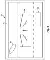
- FIG. 1illustrates a prior art display 100 .
- the screen 104is used to display a surround view of a vehicle.
- the vehicle image 102is shown in the shape of the vehicle as would be seen from an overhead camera view. No other information about the vehicle 102 is shared on the display 100 .
- information about the vehiclewould be shown by splitting the screen 104 into two portions, one portion showing the surround view of the vehicle and the other portion showing information about the vehicle or the view from a different camera. Splitting the screen 104 into two screens causes the information to be less comprehensible as the images must become smaller. There is a desire to improve utilization of the display.
- a controller for synthesizing images for a vehicle displaycomprise a first image generator for generating a bird's eye image from a first set of cameras, the bird's eye image depicting the surroundings of a host vehicle and having a generally central portion.
- the controllerincludes a second image generator for generating a second image separate from the bird's eye image.
- the controlleralso includes a synthesizer for synthesizing the bird's eye image and the second image for displaying the second image within the generally central portion of the bird's eye image.
- various embodiments of a method for synthesizing an imagecomprise receiving a bird's eye view of a surrounding of a vehicle from a first set of cameras and synthesizing the bird's eye view to create a bird's eye image having a generally central portion.
- the methodalso includes receiving a second view separate from the bird's eye view and synthesizing the second view to create a second image.
- the methodincludes displaying the second image within the generally central portion of the bird's eye image.
- FIG. 1illustrates a prior art display
- FIG. 2illustrates a system according to one example of this invention.
- FIGS. 3-12illustrate displays configured according to examples of this invention.
- FIGS. 13-14illustrate methods of utilizing the display according to examples of this invention.
- FIG. 2illustrates a surround view system 10 according to one example.
- the surround view system 10is installed on host vehicle, such as a car, bus, truck or tractor-trailer vehicle.
- the surround view system 10captures a bird's eye view of the host vehicle on which the surround view system 10 is installed, in addition to other features, as will be explained.
- the surround view system 10includes at least one forward looking camera 16 , intended for installation on the front of the body of the host vehicle.
- the surround view system 10also includes a rear camera 18 , intended for installation on the rear of the host vehicle.
- the surround view system 10also includes a left side camera 20 and a right side camera 22 that may be mounted on the left and right sides of the host vehicle.
- the camerasmay be mounted on the roof of the vehicle, along the perimeter of the vehicle, on the hood of the vehicle or other location that affords a view looking downward and around the host vehicle.
- the cameras 16 , 18 , 20 , 22may have a fish eye lens to facilitate capturing the bird's eye view.
- the surround view system 10may also include at least one alternate camera 24 .
- the at least one alternate camera 24may be a driver facing camera, an undercarriage camera, a panorama camera, a cargo or passenger space camera or other camera that captures another view of the host vehicle or around the host vehicle that is not typically used to display a bird's eye image of a vehicle.
- the surround view system 10includes a display 12 .
- the display 12is located in the host vehicle in view of a driver.
- the display 12may be an UM-900/T display from Lilliput Electronics Inc. of City of Industry, Calif.
- the display 12is in electrical communication with a surround view controller 14 either directly, wirelessly, through a vehicle communications bus 13 or other communications means.
- the vehicle communications bus 13may be used to transmit or receive information from other controllers on the host vehicle.
- the surround view controller 14includes a processor with control logic 15 for controlling the display 12 and receiving information from the cameras 16 , 18 , 20 , 22 , 24 .
- the control logic 15compiles each of the views from cameras 16 , 18 , 20 , 22 in a first image generator 28 to create the bird's eye view image.
- the control logic 15compiles the view from alternate camera 24 and/or other information from other systems on the vehicle in a second image generator 30 .
- the control logic 15synthesizes the information from the first image generator 28 and the second image generator 30 to display a unified image on the display 12 .
- a display screen of the display 12is transformed to display the unified image.
- the control logic 15may include volatile, non-volatile memory, solid state memory, flash memory, random-access memory (RAM), read-only memory (ROM), electronic erasable programmable read-only memory (EEPROM), variants of the foregoing memory types, combinations thereof, and/or any other type(s) of memory suitable for providing the described functionality and/or storing computer-executable instructions for execution by the control logic 15 .
- the control logic 15can save images to a memory location for later retrieval.
- the controller 14may also include functionality for lane departure warning and other vehicle systems.
- the surround view controller 14may receive input from a driver input device 26 .
- the driver input device 26may communicate directly with the display 12 .
- the driver input device 26is used by the driver when he or she desires to change the view as shown on the display 12 .
- a controller for synthesizing images for a vehicle displaycomprise a first image generator for generating a bird's eye image from a first set of cameras, the bird's eye image depicting the surroundings of a host vehicle and having a generally central portion.
- the controllerincludes a second image generator for generating a second image separate from the bird's eye image.
- the controlleralso includes a synthesizer for synthesizing the bird's eye image and the second image for displaying the second image within the generally central portion of the bird's eye image.
- a system for synthesizing and displaying an imagecomprises a first set of cameras for capturing a bird's eye view of a surrounding of a vehicle.
- the systemincludes a controller capable of synthesizing the bird's eye view to create a bird's eye image having a generally central portion and synthesizing a second image.
- the second imageis placed in the generally central portion of the bird's eye image to create a unified image.
- the systemalso includes a display for displaying the unified image.
- FIG. 3illustrates a close up view of the screen 42 of display 12 , according to one example of the invention.
- Display 12shows a bird's eye image around the host vehicle having the surround view system 10 .
- the control logic 15receives views acquired by the cameras 16 , 18 , 20 , 22 as arranged on the host vehicle.
- the cameras 16 , 18 , 20 , 22may be configured to capture views simultaneously and at the same frame rate.
- the fields of view of the cameras 16 , 18 , 20 , 22may and typically do have some overlap.
- the first image generator 28transforms and stitches together views captured by the cameras 16 , 18 , 20 , 22 to build the bird's eye image based on the known relative position between the cameras 16 , 18 , 20 , 22 .
- the first image generator 28then displays the bird's eye image on the screen 42 .
- Detected objectssuch as a pedestrian object 38 and vehicle object 39 , may also be shown on the screen 42 .
- the pedestrian object 38 and vehicle object 39are shown as outlines, but they may also be shown as icons, text or symbols.
- the first image generator 28creates a generally central portion 36 relative to which the bird's eye image as synthesized from cameras 16 , 18 , 20 , 22 is oriented.
- a representation of the host vehicle roofwould be displayed.
- the generally central portion 36is used by the second image generator 30 , as will be explained.
- the generally central portion 36is left as a blank space approximating the size of unviewable space of the bird's eye image. Unviewable space is created due to the placement of the cameras 16 , 18 , 20 , 22 in relationship with the body of the host vehicle.
- the generally central portion 36may be generally rectangular in shape, indicating a larger host vehicle like a tractor-trailer or a bus, or the generally central portion 36 may be squarer in shape, indicating a smaller host vehicle like a tractor only or a car. While the bird's eye image on screen 42 may change as the object(s) move with respect to the host vehicle, the generally central portion 36 corresponds to the unviewable space of the bird's eye image and remains devoid of information or graphics. This unified image is displayed to the driver.
- the first image generator 28is used to show the bird's eye image of the host vehicle on screen 42 .
- the generally central portion 36is now used to display an image of the current time, the vehicle speed and the ambient temperature.
- the vehicle speed informationmay be received by the control logic 15 from another controller on the host vehicle via the vehicle serial communications bus 13 .
- the drivermay use driver input device 26 to cycle through different information to be displayed in the generally central portion 36 .
- One display selectionmay include multiple points regarding current vehicle running information, as shown in the unified image of FIG. 5 .
- Another selectionmay present information individually, such as vehicle speed, ambient temperature, vehicle system activity and the like.
- Utilization of generally central portion 36 in the manner disclosedprecludes the second image generator 30 from overlapping information onto the bird's eye image generated by the first image generator 28 . Displaying text over any part of the image on the screen 42 may cause the driver to miss important information, such as pedestrian object 38 and vehicle object 39 .
- the full portion of the screen 42is used for the bird's eye image rather than splitting the screen 42 into two smaller images as in the prior art.
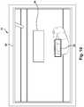
- the first image generator 28is used to show the bird's eye image of the host vehicle on screen 42 .
- the host vehicle in this exampleis a tractor-trailer vehicle.
- the bird's eye view imagewill change as the host vehicle moves or as the object(s) move in relationship to the host vehicle.
- the generally central portion 36is split into two segments, a first, or tractor, segment 40 and a second, or trailer, segment 32 .
- the tractor segment 40 and trailer segment 32approximate the location of the tractor and trailer with respect to the camera view and may remain stationary on the screen 42 as the bird's eye image changes.
- the tractor segment 40may move on the screen 42 when the controller 14 receives information that the tractor is articulating from the trailer.
- the tractor segment 40is shown as moving to the left because the controller 14 received information from another controller or sensor that the host vehicle was turning to the left.
- Display 12is used to indicate visually to a driver that his maneuvers may bring his vehicle close to vehicle object 39 .
- the generally central portion 36may display information about the vehicle object 39 , such as the size of the detected object, the distance of the detected object from the host vehicle and the direction of travel of the detected object.
- the first image generator 28is used to show the bird's eye image of the host vehicle on screen 42 .
- the tractor of the host vehicleis articulating from the trailer, similar to FIG. 6 .
- the generally central portion 36is now used to display an image of a vehicle warning as received from the second image generator 30 .
- the controller 14may generate the warning itself or may receive the warning from another controller via the vehicle serial communications bus 13 .
- a low tire pressure warning and location of the warningis displayed to the driver in the generally central portion 36 .
- the warningmay be displayed the entire time the warning is active or multiple warnings may be cyclically displayed according to their priority.
- a color change of the generally central portion 36may help the driver identify the priority of the warning. In the case of a low tire pressure warning, the background of the trailer segment 32 may turn yellow.
- the tractor segment 40may be used to visually display a graphic of the warning since the area of the tractor segment 40 is less than the area of the trailer segment 32 .
- the graphic of a tire pressure warningis shown on the tractor segment 40 in approximately the location of the tire pressure warning, the left front tire.
- the trailer segment 32may continue to provide details about the warning since it has larger spatial area on the screen 42 .
- the drivermay use driver input device 26 to cycle through different displays, one of which would include active warnings and fault codes of the vehicle.
- the drivermay use driver input device 26 to cycle through warnings, but the control logic 15 may default to displaying the warning(s) once no input is received from the driver input device 26 instead of remaining on a vehicle informational or alternate camera display.
- the first image generator 28is used to show the bird's eye image of the host vehicle on screen 42 .
- Generally central portion 36can be used to display an image from another camera on the host vehicle.
- the drivermay use the driver input device 26 to choose which camera view to display in generally central portion 36 .
- the displaymay cycle through different views from different active cameras.
- the second image generator 30uses the image from the alternate camera 24 to show a driver facing camera image in generally central portion 36 .
- the generally central portion 36may provide a space to display a live video link to an external party or to receive transmitted content.
- the first image generator 28is used to show the bird's eye image of the host vehicle.
- Generally central portion 36can be used to display yet another image from another alternate camera on the host vehicle.
- the drivermay use the driver input device 26 to choose which camera image to display in generally central portion 36 .
- the display 12may automatically cycle through different views from different cameras.
- the display 12may auto-configure to match vehicular conditions.
- the control logic 15may receive information regarding the host vehicle being in a reverse gear.
- the second image generator 30will then use the image from the alternate camera 24 in response to the vehicle being in reverse gear to show a backup camera image in the generally central portion 36 .
- Additional informationmay be gathered and displayed by the second image generator 30 .
- the driveruses the driver input device 26 to select an image from one of the cameras 16 , 18 , 20 , 22 , 24 on which the driver wants to zoom in on an area of concern.
- the alternate camera 24may be a camera arranged to determine the height of the vehicle and to generate warnings regarding upcoming bridge clearances.
- the second image generator 30may change what is displayed based on the vehicle speed, time of day or state of the driver.
- the first image generator 28is used to show the bird's eye image of the host vehicle with actual images produced by the cameras 16 , 18 , 20 , 22 and synthesized by the first image generator 28 .
- the screen 42shows an image of vehicle object 39 with the perspective of looking at the roof of the vehicle object 39 .
- the generally central portion 36is white to clearly contrast with the surrounding bird's eye image.
- the generally central portion 36may be left blank to promote “negative space” in order to draw attention to the more important information of the images of potential obstacles surrounding the host vehicle. In other words, by not showing the image of the host vehicle, the driver may focus on only the relevant, surrounding information.
- the first image generator 28is used to show the bird's eye image of the host vehicle.
- the generally central portion 36may be tinted so as to have less contrast with the surrounding bird's eye image.
- Additional information about the vehiclesuch as the speed limit for the local area, may be displayed in different colors in the generally central portion 36 . Different colors may be used to draw attention to the information in the generally central portion 36 according to the priority of the information. The colors may also be changed according to the time of day, interior lighting or the preference of the driver.
- the second image generator 30may still display vehicle information and warnings in the generally central portion 36 of the screen 42 .
- the first image generator 28is used to show the bird's eye image of the host vehicle as it is approaching an intersection.
- the generally central portion 36is not used to display information but rather is shown as an outline of the host vehicle.
- the outlinemay be filled with a color similar to the pavement on which the host vehicle is traveling.
- FIG. 12displays the bounds of the unviewable area with the minimal required spatial information, as the location of the front and rear of the host vehicle are understood. This display offers minimal distraction by using the same gray inside the vehicle outline as outside the vehicle outline.
- the coloringmay be determined by looking at the average gray level or color along the viewable boundary. The color may also be predicted by using the background from previous frames when the host vehicle was in a different position.
- Gradient shading inside the outlinemay be used, for example if the nose is assigned a brighter color than the end, the coloring may be modulated to a darker coloring at the end of the outline. Gradient shading and smooth boundary matching may be done via interpolation.
- the second image generator 30may utilize what is at the boundaries of the unviewable space in the bird's eye image and sytnthesize an image near to what the image would look like if the vehicle was not present. Otherwise, the generally central section 36 displays no other information about the host vehicle and is not representing the vehicle in any manner except by its general shape.
- Each generally central portion 36 as depicted in FIGS. 3-12may change according to the task the driver is completing, the driver status or driver preference.
- FIG. 13illustrates a method 50 of synthesizing and displaying an image.
- step 52the bird's eye image of the host vehicle as generated by the first image generator 28 of the surround view system 10 is displayed on the screen 42 .
- step 54basic vehicle and ambient information, such as vehicle speed and temperature, is displayed in the generally central portion 36 of the display by the second image generator 30 , similar to FIG. 5 .
- step 56the control logic 15 determines if a fault occurred anywhere in the host vehicle via messages on the vehicle communications bus 13 . If there are no faults in the host vehicle, the method 50 returns to step 54 to continue to display the basic vehicle and ambient information. If the controller 14 receives a message that the host vehicle has a fault, the method 50 continues to step 58 .
- step 58the second image generator 30 displays the fault, such as the low tire pressure warning, similar to FIG. 7 .
- the driver input device 26may be disabled so that the driver cannot change the images on the display 12 .
- step 60the controller 14 determines if the fault has been cleared. Once the fault has been cleared, the method 50 returns to step 54 to display the vehicle and ambient information. The driver may then use the input device 26 to change the display as she chooses. If the fault has not been cleared, the method 50 returns to step 58 to continue to display the warning.
- FIG. 14illustrates another method 70 of changing the view in the display screen 42 .
- the bird's eye view of the vehicle as generated by the first image generator 28is displayed on the screen 42 .
- the control logic 15determines if the vehicle is in reverse gear, either by its own sensors, cameras 16 , 18 , 20 , 22 or by means of receiving a message on the vehicle communications bus 13 . If the host vehicle is not in reverse gear, the basic vehicle and ambient information is displayed in generally central portion 36 in step 78 , similar to FIG. 5 .
- step 76the information from the alternate camera 24 is displayed by the second image generator in the generally central portion 36 , similar to FIG. 9 .
- the alternate camera 24 in this exampleis a backup camera.
- the method 60returns to step 74 where the rear view image will continue to be displayed in generally central portion 36 as long as the host vehicle is in reverse gear.
- the driver of the host vehiclecan modify the view in the generally central portion 36 by using the driver input device 26 .
- the control logic 15can prevent the driver from changing the view back to the basic vehicle information or alternate camera view until the driver alert or warning is addressed.
- control logic 15can save the composite image generated by the first image generator 28 and second image generator 30 exactly as how the image would have appeared on the screen 42 to the driver.
- the control logic 15no longer saves “empty space” or unviewable space by saving the representative images of the top view or roof of a host vehicle, but rather saves the images generated by the second image generator 30 on the screen 42 in the generally central portion 36 .
- No additional framesare needed to capture warnings or other information that may have previously been on a separate display. Relevant information will not be lost due to the display switching between the bird's eye view and the warning screens, as in the prior art.
- a method for synthesizing an imagecomprises receiving a bird's eye view of a surrounding of a vehicle from a first set of cameras and synthesizing the bird's eye view to create a bird's eye image having a generally central portion.
- the methodalso includes receiving a second view separate from the bird's eye view and synthesizing the second view to create a second image.
- the methodincludes displaying the second image within the generally central portion of the bird's eye image.
Landscapes
- Engineering & Computer Science (AREA)
- Mechanical Engineering (AREA)
- Chemical & Material Sciences (AREA)
- Combustion & Propulsion (AREA)
- Transportation (AREA)
- Multimedia (AREA)
- Signal Processing (AREA)
- Physics & Mathematics (AREA)
- General Physics & Mathematics (AREA)
- Theoretical Computer Science (AREA)
- Closed-Circuit Television Systems (AREA)
- Image Processing (AREA)
Abstract
Description
Claims (14)
Priority Applications (2)
| Application Number | Priority Date | Filing Date | Title |
|---|---|---|---|
| US15/354,182US10594934B2 (en) | 2016-11-17 | 2016-11-17 | Vehicle display |
| PCT/US2017/058274WO2018093541A1 (en) | 2016-11-17 | 2017-10-25 | Vehicle display |
Applications Claiming Priority (1)
| Application Number | Priority Date | Filing Date | Title |
|---|---|---|---|
| US15/354,182US10594934B2 (en) | 2016-11-17 | 2016-11-17 | Vehicle display |
Publications (2)
| Publication Number | Publication Date |
|---|---|
| US20180139384A1 US20180139384A1 (en) | 2018-05-17 |
| US10594934B2true US10594934B2 (en) | 2020-03-17 |
Family
ID=61028154
Family Applications (1)
| Application Number | Title | Priority Date | Filing Date |
|---|---|---|---|
| US15/354,182Active2037-06-08US10594934B2 (en) | 2016-11-17 | 2016-11-17 | Vehicle display |
Country Status (2)
| Country | Link |
|---|---|
| US (1) | US10594934B2 (en) |
| WO (1) | WO2018093541A1 (en) |
Cited By (2)
| Publication number | Priority date | Publication date | Assignee | Title |
|---|---|---|---|---|
| US20230001984A1 (en)* | 2019-12-16 | 2023-01-05 | Magna Electronics Inc. | Vehicular trailering guidance system |
| US11846947B2 (en) | 2021-05-11 | 2023-12-19 | Cnh Industrial Canada, Ltd. | Systems and methods for an implement imaging system |
Families Citing this family (3)
| Publication number | Priority date | Publication date | Assignee | Title |
|---|---|---|---|---|
| BR112021021246A2 (en) | 2019-05-03 | 2021-12-21 | Stoneridge Electronics Ab | Vehicle registration system using event detection |
| DE102019212124B4 (en)* | 2019-08-13 | 2023-09-14 | Audi Ag | Motor vehicle and method for operating a motor vehicle |
| US20230306707A1 (en)* | 2022-03-28 | 2023-09-28 | Hl Klemove Corp. | Around view monitoring system and the method thereof |
Citations (41)
| Publication number | Priority date | Publication date | Assignee | Title |
|---|---|---|---|---|
| US6923080B1 (en) | 2000-07-20 | 2005-08-02 | Daimlerchrysler Ag | Device and method for monitoring the surroundings of an object |
| US20060210114A1 (en)* | 2005-03-02 | 2006-09-21 | Denso Corporation | Drive assist system and navigation system for vehicle |
| US7145519B2 (en)* | 2002-04-18 | 2006-12-05 | Nissan Motor Co., Ltd. | Image display apparatus, method, and program for automotive vehicle |
| US7317813B2 (en) | 2001-06-13 | 2008-01-08 | Denso Corporation | Vehicle vicinity image-processing apparatus and recording medium |
| US7432799B2 (en) | 2004-11-09 | 2008-10-07 | Alpine Electronics, Inc. | Driving support apparatus and driving support method |
| US20090015675A1 (en)* | 2007-07-09 | 2009-01-15 | Sanyo Electric Co., Ltd. | Driving Support System And Vehicle |
| US7592928B2 (en)* | 2005-06-07 | 2009-09-22 | Nissan Motor Co., Ltd. | Image display device and method |
| US20100220190A1 (en)* | 2009-02-27 | 2010-09-02 | Hyundai Motor Japan R&D Center, Inc. | Apparatus and method for displaying bird's eye view image of around vehicle |
| US7840032B2 (en)* | 2005-10-04 | 2010-11-23 | Microsoft Corporation | Street-side maps and paths |
| US20110050886A1 (en) | 2009-08-27 | 2011-03-03 | Robert Bosch Gmbh | System and method for providing guidance information to a driver of a vehicle |
| US7903843B2 (en)* | 2006-03-31 | 2011-03-08 | Denso Corporation | System, program, and apparatus for image processing |
| US8085990B2 (en)* | 2006-07-28 | 2011-12-27 | Microsoft Corporation | Hybrid maps with embedded street-side images |
| US8139820B2 (en) | 2006-12-13 | 2012-03-20 | Smartdrive Systems Inc. | Discretization facilities for vehicle event data recorders |
| US20120162427A1 (en)* | 2010-12-22 | 2012-06-28 | Magna Mirrors Of America, Inc. | Vision display system for vehicle |
| US8315433B2 (en)* | 2009-07-31 | 2012-11-20 | Automotive Research & Test Center | Obstacle determination system and method implemented through utilizing bird's-eye-view images |
| US20130057689A1 (en) | 2010-04-15 | 2013-03-07 | Valeo Schalter Und Sensoren Gmbh | Method for displaying an image on a display device in a vehicle, driver assistance system and vehicle |
| US8411245B2 (en) | 2009-02-06 | 2013-04-02 | Gentex Corporation | Multi-display mirror system and method for expanded view around a vehicle |
| US20130300869A1 (en)* | 2012-03-27 | 2013-11-14 | Magna Electronics Inc. | Vehicle vision system with lens pollution detection |
| US20130314503A1 (en)* | 2012-05-18 | 2013-11-28 | Magna Electronics Inc. | Vehicle vision system with front and rear camera integration |
| US20140067206A1 (en)* | 2012-09-04 | 2014-03-06 | Magna Electronics Inc. | Driver assistant system using influence mapping for conflict avoidance path determination |
| US20140088824A1 (en) | 2011-05-13 | 2014-03-27 | Hitachi Construction Machinery Co., Ltd. | Device for Monitoring Area Around Working Machine |
| US20140111648A1 (en)* | 2011-06-02 | 2014-04-24 | Hitachi Contruction Machinery Co., Ltd. | Device For Monitoring Area Around Working Machine |
| US20140218531A1 (en) | 2011-08-26 | 2014-08-07 | Panasonic Corporation | Driving assistance apparatus |
| US20140333729A1 (en)* | 2011-12-09 | 2014-11-13 | Magna Electronics Inc. | Vehicle vision system with customized display |
| US20140375814A1 (en)* | 2012-01-12 | 2014-12-25 | Hitachi Construction Machinery Co., Ltd. | Periphery Monitoring Device for Self-Propelled Industrial Machine |
| US9041806B2 (en)* | 2009-09-01 | 2015-05-26 | Magna Electronics Inc. | Imaging and display system for vehicle |
| US20150166062A1 (en)* | 2013-12-12 | 2015-06-18 | Magna Electronics Inc. | Vehicle control system with traffic driving control |
| US20150175071A1 (en)* | 2012-07-27 | 2015-06-25 | Hitachi Construction Machinery Co., Ltd. | Environment monitoring device for operating machinery |
| US20150208041A1 (en)* | 2012-08-30 | 2015-07-23 | Denso Corporation | Image processing device and storage medium |
| US20150217690A1 (en) | 2012-09-21 | 2015-08-06 | Komatsu Ltd. | Working vehicle periphery monitoring system and working vehicle |
| US9128354B2 (en) | 2012-11-29 | 2015-09-08 | Bendix Commercial Vehicle Systems Llc | Driver view adapter for forward looking camera |
| US20150286878A1 (en) | 2014-04-08 | 2015-10-08 | Bendix Commercial Vehicle Systems Llc | Generating an Image of the Surroundings of an Articulated Vehicle |
| US20150296154A1 (en)* | 2013-10-18 | 2015-10-15 | The Lightco Inc. | Image capture related methods and apparatus |
| US20160026878A1 (en)* | 2014-07-23 | 2016-01-28 | GM Global Technology Operations LLC | Algorithm to extend detecting range for avm stop line detection |
| US20160026877A1 (en)* | 2014-07-23 | 2016-01-28 | GM Global Technology Operations LLC | Fast and robust stop line detector |
| US20160101734A1 (en)* | 2014-10-13 | 2016-04-14 | Lg Electronics Inc. | Under vehicle image provision apparatus and vehicle including the same |
| US9332229B2 (en)* | 2010-06-18 | 2016-05-03 | Hitachi Construction Machinery Co., Ltd. | Surrounding area monitoring device for monitoring area around work machine |
| US20160165148A1 (en) | 2013-07-11 | 2016-06-09 | Denso Corporation | Image synthesizer for vehicle |
| US9403484B2 (en)* | 2011-11-28 | 2016-08-02 | Trailertrack Aps | System for controlling the adjustment of a side rearview device |
| US20160253058A1 (en)* | 2015-03-01 | 2016-09-01 | Google Inc. | Skimming to and past points of interest in digital content |
| US9446713B2 (en)* | 2012-09-26 | 2016-09-20 | Magna Electronics Inc. | Trailer angle detection system |
- 2016
- 2016-11-17USUS15/354,182patent/US10594934B2/enactiveActive
- 2017
- 2017-10-25WOPCT/US2017/058274patent/WO2018093541A1/ennot_activeCeased
Patent Citations (44)
| Publication number | Priority date | Publication date | Assignee | Title |
|---|---|---|---|---|
| US6923080B1 (en) | 2000-07-20 | 2005-08-02 | Daimlerchrysler Ag | Device and method for monitoring the surroundings of an object |
| US7317813B2 (en) | 2001-06-13 | 2008-01-08 | Denso Corporation | Vehicle vicinity image-processing apparatus and recording medium |
| US7145519B2 (en)* | 2002-04-18 | 2006-12-05 | Nissan Motor Co., Ltd. | Image display apparatus, method, and program for automotive vehicle |
| US7432799B2 (en) | 2004-11-09 | 2008-10-07 | Alpine Electronics, Inc. | Driving support apparatus and driving support method |
| US20060210114A1 (en)* | 2005-03-02 | 2006-09-21 | Denso Corporation | Drive assist system and navigation system for vehicle |
| US7592928B2 (en)* | 2005-06-07 | 2009-09-22 | Nissan Motor Co., Ltd. | Image display device and method |
| US7840032B2 (en)* | 2005-10-04 | 2010-11-23 | Microsoft Corporation | Street-side maps and paths |
| US7903843B2 (en)* | 2006-03-31 | 2011-03-08 | Denso Corporation | System, program, and apparatus for image processing |
| US8085990B2 (en)* | 2006-07-28 | 2011-12-27 | Microsoft Corporation | Hybrid maps with embedded street-side images |
| US8139820B2 (en) | 2006-12-13 | 2012-03-20 | Smartdrive Systems Inc. | Discretization facilities for vehicle event data recorders |
| US20090015675A1 (en)* | 2007-07-09 | 2009-01-15 | Sanyo Electric Co., Ltd. | Driving Support System And Vehicle |
| US8411245B2 (en) | 2009-02-06 | 2013-04-02 | Gentex Corporation | Multi-display mirror system and method for expanded view around a vehicle |
| US20100220190A1 (en)* | 2009-02-27 | 2010-09-02 | Hyundai Motor Japan R&D Center, Inc. | Apparatus and method for displaying bird's eye view image of around vehicle |
| US8315433B2 (en)* | 2009-07-31 | 2012-11-20 | Automotive Research & Test Center | Obstacle determination system and method implemented through utilizing bird's-eye-view images |
| US20110050886A1 (en) | 2009-08-27 | 2011-03-03 | Robert Bosch Gmbh | System and method for providing guidance information to a driver of a vehicle |
| US9041806B2 (en)* | 2009-09-01 | 2015-05-26 | Magna Electronics Inc. | Imaging and display system for vehicle |
| US20130057689A1 (en) | 2010-04-15 | 2013-03-07 | Valeo Schalter Und Sensoren Gmbh | Method for displaying an image on a display device in a vehicle, driver assistance system and vehicle |
| US9332229B2 (en)* | 2010-06-18 | 2016-05-03 | Hitachi Construction Machinery Co., Ltd. | Surrounding area monitoring device for monitoring area around work machine |
| US20120162427A1 (en)* | 2010-12-22 | 2012-06-28 | Magna Mirrors Of America, Inc. | Vision display system for vehicle |
| US9469250B2 (en)* | 2010-12-22 | 2016-10-18 | Magna Electronics Inc. | Vision display system for vehicle |
| US9264672B2 (en)* | 2010-12-22 | 2016-02-16 | Magna Mirrors Of America, Inc. | Vision display system for vehicle |
| US20140088824A1 (en) | 2011-05-13 | 2014-03-27 | Hitachi Construction Machinery Co., Ltd. | Device for Monitoring Area Around Working Machine |
| US20140111648A1 (en)* | 2011-06-02 | 2014-04-24 | Hitachi Contruction Machinery Co., Ltd. | Device For Monitoring Area Around Working Machine |
| US20140218531A1 (en) | 2011-08-26 | 2014-08-07 | Panasonic Corporation | Driving assistance apparatus |
| US9403484B2 (en)* | 2011-11-28 | 2016-08-02 | Trailertrack Aps | System for controlling the adjustment of a side rearview device |
| US20140333729A1 (en)* | 2011-12-09 | 2014-11-13 | Magna Electronics Inc. | Vehicle vision system with customized display |
| US20140375814A1 (en)* | 2012-01-12 | 2014-12-25 | Hitachi Construction Machinery Co., Ltd. | Periphery Monitoring Device for Self-Propelled Industrial Machine |
| US9319637B2 (en)* | 2012-03-27 | 2016-04-19 | Magna Electronics Inc. | Vehicle vision system with lens pollution detection |
| US20130300869A1 (en)* | 2012-03-27 | 2013-11-14 | Magna Electronics Inc. | Vehicle vision system with lens pollution detection |
| US20130314503A1 (en)* | 2012-05-18 | 2013-11-28 | Magna Electronics Inc. | Vehicle vision system with front and rear camera integration |
| US20150175071A1 (en)* | 2012-07-27 | 2015-06-25 | Hitachi Construction Machinery Co., Ltd. | Environment monitoring device for operating machinery |
| US20150208041A1 (en)* | 2012-08-30 | 2015-07-23 | Denso Corporation | Image processing device and storage medium |
| US20140067206A1 (en)* | 2012-09-04 | 2014-03-06 | Magna Electronics Inc. | Driver assistant system using influence mapping for conflict avoidance path determination |
| US20150217690A1 (en) | 2012-09-21 | 2015-08-06 | Komatsu Ltd. | Working vehicle periphery monitoring system and working vehicle |
| US9446713B2 (en)* | 2012-09-26 | 2016-09-20 | Magna Electronics Inc. | Trailer angle detection system |
| US9128354B2 (en) | 2012-11-29 | 2015-09-08 | Bendix Commercial Vehicle Systems Llc | Driver view adapter for forward looking camera |
| US20160165148A1 (en) | 2013-07-11 | 2016-06-09 | Denso Corporation | Image synthesizer for vehicle |
| US20150296154A1 (en)* | 2013-10-18 | 2015-10-15 | The Lightco Inc. | Image capture related methods and apparatus |
| US20150166062A1 (en)* | 2013-12-12 | 2015-06-18 | Magna Electronics Inc. | Vehicle control system with traffic driving control |
| US20150286878A1 (en) | 2014-04-08 | 2015-10-08 | Bendix Commercial Vehicle Systems Llc | Generating an Image of the Surroundings of an Articulated Vehicle |
| US20160026877A1 (en)* | 2014-07-23 | 2016-01-28 | GM Global Technology Operations LLC | Fast and robust stop line detector |
| US20160026878A1 (en)* | 2014-07-23 | 2016-01-28 | GM Global Technology Operations LLC | Algorithm to extend detecting range for avm stop line detection |
| US20160101734A1 (en)* | 2014-10-13 | 2016-04-14 | Lg Electronics Inc. | Under vehicle image provision apparatus and vehicle including the same |
| US20160253058A1 (en)* | 2015-03-01 | 2016-09-01 | Google Inc. | Skimming to and past points of interest in digital content |
Non-Patent Citations (2)
| Title |
|---|
| European Patent Office, "Written Opinion and Search Report of the International Searching Authority," Written Opinion and Search Report, dated Mar. 19, 2018, 8 pages, European Patent Office, Berlin Germany. |
| lilliputweb.net "Specifications of UM-900/C/T," Technical Document, Unknown publication date, 3 pages, lilliputweb.net, City of Industry, California. |
Cited By (3)
| Publication number | Priority date | Publication date | Assignee | Title |
|---|---|---|---|---|
| US20230001984A1 (en)* | 2019-12-16 | 2023-01-05 | Magna Electronics Inc. | Vehicular trailering guidance system |
| US12258065B2 (en)* | 2019-12-16 | 2025-03-25 | Magna Electronics Inc. | Vehicular trailering guidance system |
| US11846947B2 (en) | 2021-05-11 | 2023-12-19 | Cnh Industrial Canada, Ltd. | Systems and methods for an implement imaging system |
Also Published As
| Publication number | Publication date |
|---|---|
| US20180139384A1 (en) | 2018-05-17 |
| WO2018093541A1 (en) | 2018-05-24 |
Similar Documents
| Publication | Publication Date | Title |
|---|---|---|
| US10594934B2 (en) | Vehicle display | |
| US11034299B2 (en) | Vehicular vision system with episodic display of video images showing approaching other vehicle | |
| EP2476587B1 (en) | Vehicle surrounding monitor apparatus | |
| EP2476588B1 (en) | Vehicle surrounding monitor apparatus | |
| EP3147149B1 (en) | Display device | |
| US6912001B2 (en) | Image processor and monitoring system | |
| JP5421788B2 (en) | Vehicle periphery image display system | |
| US9969330B2 (en) | Mirror substitute device and vehicle | |
| JP2008001182A (en) | Visual information presentation device for vehicle and visual information presentation method for vehicle | |
| US20160046289A1 (en) | Method of Warning Road Users of Potential Danger Areas Caused by a Vehicle that is or Will be Performing a Maneuver | |
| US10192121B2 (en) | Display device for a vehicle, in particular a commercial vehicle | |
| JP2008033901A (en) | Image display system for vehicles | |
| KR102468922B1 (en) | Method and apparatus for operating a camera monitor system for a vehicle | |
| CN113401059B (en) | Display system and method for compensating visual field blind area of trailer rearview mirror | |
| US11420680B2 (en) | Method for assisting a user of a motor vehicle when swerving around an obstacle, driver assistance device, and a motor vehicle | |
| JP2004323005A (en) | Method for depicting various image data on vehicle display device | |
| KR101428094B1 (en) | Lane-indicated lateral / rear image providing system | |
| JP2022149734A (en) | Vehicle control device, vehicle, vehicle control device operation method, and program | |
| JP4706896B2 (en) | Wide-angle image correction method and vehicle periphery monitoring system | |
| JP2018008578A (en) | Display device | |
| JP2014021543A (en) | Visual field support device and program for vehicle | |
| JP2019110390A (en) | Vehicle periphery monitoring device | |
| JP2003264827A (en) | Image processing device | |
| DE102020122977A1 (en) | Driver assistance system and driver assistance method for a vehicle | |
| JP2020199969A (en) | Display control device, display system, and display control method |
Legal Events
| Date | Code | Title | Description |
|---|---|---|---|
| STPP | Information on status: patent application and granting procedure in general | Free format text:FINAL REJECTION MAILED | |
| STPP | Information on status: patent application and granting procedure in general | Free format text:ADVISORY ACTION MAILED | |
| STPP | Information on status: patent application and granting procedure in general | Free format text:NON FINAL ACTION MAILED | |
| STPP | Information on status: patent application and granting procedure in general | Free format text:RESPONSE TO NON-FINAL OFFICE ACTION ENTERED AND FORWARDED TO EXAMINER | |
| STPP | Information on status: patent application and granting procedure in general | Free format text:NOTICE OF ALLOWANCE MAILED -- APPLICATION RECEIVED IN OFFICE OF PUBLICATIONS | |
| STPP | Information on status: patent application and granting procedure in general | Free format text:PUBLICATIONS -- ISSUE FEE PAYMENT RECEIVED | |
| STPP | Information on status: patent application and granting procedure in general | Free format text:PUBLICATIONS -- ISSUE FEE PAYMENT VERIFIED | |
| STCF | Information on status: patent grant | Free format text:PATENTED CASE | |
| MAFP | Maintenance fee payment | Free format text:PAYMENT OF MAINTENANCE FEE, 4TH YEAR, LARGE ENTITY (ORIGINAL EVENT CODE: M1551); ENTITY STATUS OF PATENT OWNER: LARGE ENTITY Year of fee payment:4 | |
| AS | Assignment | Owner name:BENDIX COMMERCIAL VEHICLE SYSTEMS LLC, OHIO Free format text:ASSIGNMENT OF ASSIGNORS INTEREST;ASSIGNORS:KUEHNLE, ANDREAS U.;LI, ZHENG;SIGNING DATES FROM 20161116 TO 20161117;REEL/FRAME:065748/0051 | |
| AS | Assignment | Owner name:RM ACQUISITION, LLC, IDAHO Free format text:ASSIGNMENT OF ASSIGNORS INTEREST;ASSIGNOR:BENDIX COMMERCIAL VEHICLE SYSTEMS LLC;REEL/FRAME:067824/0004 Effective date:20240307 |