US10594246B2 - Board-level motor control system with integrated protection and control components - Google Patents
Board-level motor control system with integrated protection and control componentsDownload PDFInfo
- Publication number
- US10594246B2 US10594246B2US15/854,096US201715854096AUS10594246B2US 10594246 B2US10594246 B2US 10594246B2US 201715854096 AUS201715854096 AUS 201715854096AUS 10594246 B2US10594246 B2US 10594246B2
- Authority
- US
- United States
- Prior art keywords
- control system
- power
- power converter
- protection
- motor control
- Prior art date
- Legal status (The legal status is an assumption and is not a legal conclusion. Google has not performed a legal analysis and makes no representation as to the accuracy of the status listed.)
- Active, expires
Links
- 239000000758substrateSubstances0.000claimsdescription17
- 238000011144upstream manufacturingMethods0.000claimsdescription8
- 238000000034methodMethods0.000claimsdescription7
- 238000001816coolingMethods0.000claimsdescription4
- 238000004519manufacturing processMethods0.000claimsdescription3
- 238000005476solderingMethods0.000claimsdescription3
- BZTYNSQSZHARAZ-UHFFFAOYSA-N2,4-dichloro-1-(4-chlorophenyl)benzeneChemical compoundC1=CC(Cl)=CC=C1C1=CC=C(Cl)C=C1ClBZTYNSQSZHARAZ-UHFFFAOYSA-N0.000description17
- 230000001276controlling effectEffects0.000description11
- 238000010276constructionMethods0.000description6
- 238000007726management methodMethods0.000description6
- 238000006243chemical reactionMethods0.000description5
- 238000012544monitoring processMethods0.000description5
- 238000004891communicationMethods0.000description4
- 230000010354integrationEffects0.000description4
- 239000002184metalSubstances0.000description4
- 230000008901benefitEffects0.000description3
- 230000005540biological transmissionEffects0.000description3
- 238000010586diagramMethods0.000description3
- 239000007858starting materialSubstances0.000description3
- 230000003750conditioning effectEffects0.000description2
- 238000009434installationMethods0.000description2
- 230000006855networkingEffects0.000description2
- XUIMIQQOPSSXEZ-UHFFFAOYSA-NSiliconChemical compound[Si]XUIMIQQOPSSXEZ-UHFFFAOYSA-N0.000description1
- 238000004458analytical methodMethods0.000description1
- 238000013475authorizationMethods0.000description1
- 239000003990capacitorSubstances0.000description1
- 238000007405data analysisMethods0.000description1
- 238000013500data storageMethods0.000description1
- 238000013461designMethods0.000description1
- 238000001514detection methodMethods0.000description1
- 230000007613environmental effectEffects0.000description1
- -1for exampleSubstances0.000description1
- 230000009931harmful effectEffects0.000description1
- 230000006698inductionEffects0.000description1
- 238000009413insulationMethods0.000description1
- 230000003993interactionEffects0.000description1
- 238000002955isolationMethods0.000description1
- 238000012423maintenanceMethods0.000description1
- 230000013011matingEffects0.000description1
- 230000007246mechanismEffects0.000description1
- 238000012986modificationMethods0.000description1
- 230000004048modificationEffects0.000description1
- 239000012811non-conductive materialSubstances0.000description1
- 238000013021overheatingMethods0.000description1
- 150000003071polychlorinated biphenylsChemical class0.000description1
- 230000008569processEffects0.000description1
- 238000012545processingMethods0.000description1
- 230000001105regulatory effectEffects0.000description1
- 238000005070samplingMethods0.000description1
- 229910052710siliconInorganic materials0.000description1
- 239000010703siliconSubstances0.000description1
- 239000007787solidSubstances0.000description1
- 238000012546transferMethods0.000description1
- 230000001052transient effectEffects0.000description1
Images


Classifications
- H—ELECTRICITY
- H02—GENERATION; CONVERSION OR DISTRIBUTION OF ELECTRIC POWER
- H02P—CONTROL OR REGULATION OF ELECTRIC MOTORS, ELECTRIC GENERATORS OR DYNAMO-ELECTRIC CONVERTERS; CONTROLLING TRANSFORMERS, REACTORS OR CHOKE COILS
- H02P27/00—Arrangements or methods for the control of AC motors characterised by the kind of supply voltage
- H02P27/04—Arrangements or methods for the control of AC motors characterised by the kind of supply voltage using variable-frequency supply voltage, e.g. inverter or converter supply voltage
- H02P27/045—Arrangements or methods for the control of AC motors characterised by the kind of supply voltage using variable-frequency supply voltage, e.g. inverter or converter supply voltage whereby the speed is regulated by measuring the motor speed and comparing it with a given physical value
- H—ELECTRICITY
- H02—GENERATION; CONVERSION OR DISTRIBUTION OF ELECTRIC POWER
- H02M—APPARATUS FOR CONVERSION BETWEEN AC AND AC, BETWEEN AC AND DC, OR BETWEEN DC AND DC, AND FOR USE WITH MAINS OR SIMILAR POWER SUPPLY SYSTEMS; CONVERSION OF DC OR AC INPUT POWER INTO SURGE OUTPUT POWER; CONTROL OR REGULATION THEREOF
- H02M7/00—Conversion of AC power input into DC power output; Conversion of DC power input into AC power output
- H02M7/003—Constructional details, e.g. physical layout, assembly, wiring or busbar connections
- H—ELECTRICITY
- H02—GENERATION; CONVERSION OR DISTRIBUTION OF ELECTRIC POWER
- H02H—EMERGENCY PROTECTIVE CIRCUIT ARRANGEMENTS
- H02H3/00—Emergency protective circuit arrangements for automatic disconnection directly responsive to an undesired change from normal electric working condition with or without subsequent reconnection ; integrated protection
- H02H3/08—Emergency protective circuit arrangements for automatic disconnection directly responsive to an undesired change from normal electric working condition with or without subsequent reconnection ; integrated protection responsive to excess current
- H02H3/083—Emergency protective circuit arrangements for automatic disconnection directly responsive to an undesired change from normal electric working condition with or without subsequent reconnection ; integrated protection responsive to excess current for three-phase systems
- H—ELECTRICITY
- H02—GENERATION; CONVERSION OR DISTRIBUTION OF ELECTRIC POWER
- H02H—EMERGENCY PROTECTIVE CIRCUIT ARRANGEMENTS
- H02H7/00—Emergency protective circuit arrangements specially adapted for specific types of electric machines or apparatus or for sectionalised protection of cable or line systems, and effecting automatic switching in the event of an undesired change from normal working conditions
- H02H7/08—Emergency protective circuit arrangements specially adapted for specific types of electric machines or apparatus or for sectionalised protection of cable or line systems, and effecting automatic switching in the event of an undesired change from normal working conditions for dynamo-electric motors
- H02H7/0822—Integrated protection, motor control centres
- H—ELECTRICITY
- H02—GENERATION; CONVERSION OR DISTRIBUTION OF ELECTRIC POWER
- H02H—EMERGENCY PROTECTIVE CIRCUIT ARRANGEMENTS
- H02H9/00—Emergency protective circuit arrangements for limiting excess current or voltage without disconnection
- H02H9/02—Emergency protective circuit arrangements for limiting excess current or voltage without disconnection responsive to excess current
- H—ELECTRICITY
- H02—GENERATION; CONVERSION OR DISTRIBUTION OF ELECTRIC POWER
- H02H—EMERGENCY PROTECTIVE CIRCUIT ARRANGEMENTS
- H02H9/00—Emergency protective circuit arrangements for limiting excess current or voltage without disconnection
- H02H9/04—Emergency protective circuit arrangements for limiting excess current or voltage without disconnection responsive to excess voltage
- H—ELECTRICITY
- H02—GENERATION; CONVERSION OR DISTRIBUTION OF ELECTRIC POWER
- H02M—APPARATUS FOR CONVERSION BETWEEN AC AND AC, BETWEEN AC AND DC, OR BETWEEN DC AND DC, AND FOR USE WITH MAINS OR SIMILAR POWER SUPPLY SYSTEMS; CONVERSION OF DC OR AC INPUT POWER INTO SURGE OUTPUT POWER; CONTROL OR REGULATION THEREOF
- H02M5/00—Conversion of AC power input into AC power output, e.g. for change of voltage, for change of frequency, for change of number of phases
- H02M5/40—Conversion of AC power input into AC power output, e.g. for change of voltage, for change of frequency, for change of number of phases with intermediate conversion into DC
- H02M5/42—Conversion of AC power input into AC power output, e.g. for change of voltage, for change of frequency, for change of number of phases with intermediate conversion into DC by static converters
- H02M5/44—Conversion of AC power input into AC power output, e.g. for change of voltage, for change of frequency, for change of number of phases with intermediate conversion into DC by static converters using discharge tubes or semiconductor devices to convert the intermediate DC into AC
- H02M5/453—Conversion of AC power input into AC power output, e.g. for change of voltage, for change of frequency, for change of number of phases with intermediate conversion into DC by static converters using discharge tubes or semiconductor devices to convert the intermediate DC into AC using devices of a triode or transistor type requiring continuous application of a control signal
- H02M5/458—Conversion of AC power input into AC power output, e.g. for change of voltage, for change of frequency, for change of number of phases with intermediate conversion into DC by static converters using discharge tubes or semiconductor devices to convert the intermediate DC into AC using devices of a triode or transistor type requiring continuous application of a control signal using semiconductor devices only
- H—ELECTRICITY
- H02—GENERATION; CONVERSION OR DISTRIBUTION OF ELECTRIC POWER
- H02M—APPARATUS FOR CONVERSION BETWEEN AC AND AC, BETWEEN AC AND DC, OR BETWEEN DC AND DC, AND FOR USE WITH MAINS OR SIMILAR POWER SUPPLY SYSTEMS; CONVERSION OF DC OR AC INPUT POWER INTO SURGE OUTPUT POWER; CONTROL OR REGULATION THEREOF
- H02M7/00—Conversion of AC power input into DC power output; Conversion of DC power input into AC power output
- H02M7/42—Conversion of DC power input into AC power output without possibility of reversal
- H02M7/44—Conversion of DC power input into AC power output without possibility of reversal by static converters
- H02M7/48—Conversion of DC power input into AC power output without possibility of reversal by static converters using discharge tubes with control electrode or semiconductor devices with control electrode
- H02M7/53—Conversion of DC power input into AC power output without possibility of reversal by static converters using discharge tubes with control electrode or semiconductor devices with control electrode using devices of a triode or transistor type requiring continuous application of a control signal
- H02M7/537—Conversion of DC power input into AC power output without possibility of reversal by static converters using discharge tubes with control electrode or semiconductor devices with control electrode using devices of a triode or transistor type requiring continuous application of a control signal using semiconductor devices only, e.g. single switched pulse inverters
- H02M7/5387—Conversion of DC power input into AC power output without possibility of reversal by static converters using discharge tubes with control electrode or semiconductor devices with control electrode using devices of a triode or transistor type requiring continuous application of a control signal using semiconductor devices only, e.g. single switched pulse inverters in a bridge configuration
- H02M7/53871—Conversion of DC power input into AC power output without possibility of reversal by static converters using discharge tubes with control electrode or semiconductor devices with control electrode using devices of a triode or transistor type requiring continuous application of a control signal using semiconductor devices only, e.g. single switched pulse inverters in a bridge configuration with automatic control of output voltage or current
- H02M7/53875—Conversion of DC power input into AC power output without possibility of reversal by static converters using discharge tubes with control electrode or semiconductor devices with control electrode using devices of a triode or transistor type requiring continuous application of a control signal using semiconductor devices only, e.g. single switched pulse inverters in a bridge configuration with automatic control of output voltage or current with analogue control of three-phase output
- H—ELECTRICITY
- H05—ELECTRIC TECHNIQUES NOT OTHERWISE PROVIDED FOR
- H05K—PRINTED CIRCUITS; CASINGS OR CONSTRUCTIONAL DETAILS OF ELECTRIC APPARATUS; MANUFACTURE OF ASSEMBLAGES OF ELECTRICAL COMPONENTS
- H05K1/00—Printed circuits
- H05K1/02—Details
- H05K1/0213—Electrical arrangements not otherwise provided for
- H05K1/0254—High voltage adaptations; Electrical insulation details; Overvoltage or electrostatic discharge protection ; Arrangements for regulating voltages or for using plural voltages
- H05K1/0257—Overvoltage protection
- H—ELECTRICITY
- H02—GENERATION; CONVERSION OR DISTRIBUTION OF ELECTRIC POWER
- H02H—EMERGENCY PROTECTIVE CIRCUIT ARRANGEMENTS
- H02H5/00—Emergency protective circuit arrangements for automatic disconnection directly responsive to an undesired change from normal non-electric working conditions with or without subsequent reconnection
- H02H5/04—Emergency protective circuit arrangements for automatic disconnection directly responsive to an undesired change from normal non-electric working conditions with or without subsequent reconnection responsive to abnormal temperature
- H02H5/041—Emergency protective circuit arrangements for automatic disconnection directly responsive to an undesired change from normal non-electric working conditions with or without subsequent reconnection responsive to abnormal temperature additionally responsive to excess current
- H—ELECTRICITY
- H02—GENERATION; CONVERSION OR DISTRIBUTION OF ELECTRIC POWER
- H02H—EMERGENCY PROTECTIVE CIRCUIT ARRANGEMENTS
- H02H7/00—Emergency protective circuit arrangements specially adapted for specific types of electric machines or apparatus or for sectionalised protection of cable or line systems, and effecting automatic switching in the event of an undesired change from normal working conditions
- H02H7/10—Emergency protective circuit arrangements specially adapted for specific types of electric machines or apparatus or for sectionalised protection of cable or line systems, and effecting automatic switching in the event of an undesired change from normal working conditions for converters; for rectifiers
- H02H7/12—Emergency protective circuit arrangements specially adapted for specific types of electric machines or apparatus or for sectionalised protection of cable or line systems, and effecting automatic switching in the event of an undesired change from normal working conditions for converters; for rectifiers for static converters or rectifiers
- H02H7/122—Emergency protective circuit arrangements specially adapted for specific types of electric machines or apparatus or for sectionalised protection of cable or line systems, and effecting automatic switching in the event of an undesired change from normal working conditions for converters; for rectifiers for static converters or rectifiers for inverters, i.e. DC/AC converters
- H02H7/1225—Emergency protective circuit arrangements specially adapted for specific types of electric machines or apparatus or for sectionalised protection of cable or line systems, and effecting automatic switching in the event of an undesired change from normal working conditions for converters; for rectifiers for static converters or rectifiers for inverters, i.e. DC/AC converters responsive to internal faults, e.g. shoot-through
- H—ELECTRICITY
- H02—GENERATION; CONVERSION OR DISTRIBUTION OF ELECTRIC POWER
- H02H—EMERGENCY PROTECTIVE CIRCUIT ARRANGEMENTS
- H02H9/00—Emergency protective circuit arrangements for limiting excess current or voltage without disconnection
- H02H9/001—Emergency protective circuit arrangements for limiting excess current or voltage without disconnection limiting speed of change of electric quantities, e.g. soft switching on or off
- H—ELECTRICITY
- H02—GENERATION; CONVERSION OR DISTRIBUTION OF ELECTRIC POWER
- H02P—CONTROL OR REGULATION OF ELECTRIC MOTORS, ELECTRIC GENERATORS OR DYNAMO-ELECTRIC CONVERTERS; CONTROLLING TRANSFORMERS, REACTORS OR CHOKE COILS
- H02P27/00—Arrangements or methods for the control of AC motors characterised by the kind of supply voltage
- H02P27/04—Arrangements or methods for the control of AC motors characterised by the kind of supply voltage using variable-frequency supply voltage, e.g. inverter or converter supply voltage
Definitions
- Embodiments of the inventionrelate generally to motor control systems and, more particularly, to a board-level motor control system having integrated protection and control components.
- VFDvariable frequency drive
- a VFDis an industrial control device that provides for variable frequency, variable voltage operation of a driven system, such as an AC induction motor.
- a VFDis often provided as part of a motor control system and overall control and protection assembly that includes the VFD as well as an arrangement of input/output fuses, disconnects, circuit breakers or other protection devices, controllers, filters, sensors, and a bypass assembly that includes one or more of a bypass contactor and soft starter that provide alternate control paths or mechanisms for controlling the driven system.
- the VFD and associated protection and control devicesare provided as discrete components having their own housings 4 .
- the discrete, housed components 2are positioned within a large metal enclosure 6 .
- the arrangement of components 2is fixed to a support within the enclosure 6 , such as a DIN rail for example, with wiring 8 being provided between the components 2 to provide for electrical connectivity and/or communication therebetween.
- the enclosure 6 required to house the components 2becomes quite large and bulky.
- the large amount of wiring 8 required between the components 2can hinder accessibility to the components 2 , increases installation time and the potential for failure due to wiring and wiring connections, and reduces the overall efficiency of the motor control system.
- a motor control systemfor selectively controlling power from a power source to a load.
- the motor control systemincludes at least one printed circuit board (PCB) structure and a plurality of protection and control components mounted onto the at least one PCB structure so as to be electrically coupled therewith.
- the plurality of protection and control componentsincludes a power converter operable to provide a controlled output power to the load, a plurality of switching devices operable to selectively control power flow from the power source into the power converter and to bypass the power converter, and one or more protection devices configured to selectively interrupt current flow from the power source to the power converter during a fault condition.
- the motor control systemalso includes a housing enclosing the at least one PCB structure and the plurality of protection and control components.
- a motor control systemfor selectively controlling power from a power source to a load.
- the motor control systemincludes a PCB structure comprising at least one substrate and a plurality of conductive traces formed on the at least one substrate and a motor switching assembly integrated onto the PCB structure.
- the motor switching assemblyfurther includes a power converter operable to provide a controlled output power to the load and a plurality of switching devices operable to selectively control power flow from the power source into the power converter and to bypass the power converter.
- the motor control systemalso includes a controller coupled to the PCB structure and configured to control operation of the power converter and the plurality of switching devices.
- the conductive tracesform electrical connections within the motor switching assembly and electrically connect the motor switching assembly to the controller.
- a method of manufacturing a board-level motor control system for controlling power from a power source to a loadincludes providing a PCB structure comprising at least one substrate and a plurality of conductive traces formed on the at least one substrate and mounting a plurality of protection and control components onto the PCB structure, wherein mounting the plurality of protection and control components comprises one of snapping respective plug-and-play components of the plurality of protection and control components onto the PCB structure and soldering respective components of the plurality of protection and control components onto the PCB structure.
- the methodalso includes electrically connecting the plurality of protection and control components via the plurality of conductive traces.
- FIG. 1is a schematic view of a motor control system as known in the prior art.
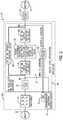
- FIG. 2is a block diagram of a board-level motor control system, according to an embodiment of the invention.
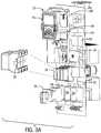
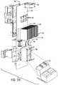
- FIGS. 3A and 3Bare perspective views of the board-level motor control system of FIG. 2 , according to an embodiment of the invention.
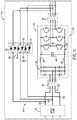
- FIG. 4is a schematic diagram of a motor switching assembly included in the motor control system of FIG. 2 and FIGS. 3A and 3B , according to an embodiment of the invention.
- FIG. 5is a perspective view of a compact housing enclosing the motor control system of FIG. 2 and FIGS. 3A and 3B , according to an embodiment of the invention.
- FIG. 6is a schematic diagram of a motor switching assembly, according to another embodiment of the invention.
- Embodiments of the inventionrelate to a compact, board-level motor control system.
- the board-level motor control systemhas integrated solid-state contactors, drives, filters, and protection devices (e.g., fuses) at a circuit board level, such that electrical connections between the components can be made via electrical traces on the board and without the use of separate cables or wires.
- a single, compact plastic enclosuremay be provided for the board-level motor control system that replaces the typical bulky metal enclosure and individual component housings that are found in existing motor control systems.
- embodiments of the inventionare described and illustrated herebelow as being directed to a motor control system, it is recognized that embodiments of the invention are not meant to be limited to such circuits. That is, embodiments of the invention may be extended more generally to power/energy conversion circuits of varying constructions and implementations, including motor starters, motor control centers, and power/energy conversion circuits for driving non-motor loads, for example. Accordingly, the following discussion of a board-level motor control system is not meant to limit the scope of the invention.
- Power system 10includes a power source 12 , such as from a utility, for example, coupled to a disconnect contactor or switch 14 that may be operated in a closed or On position in which power from utility 12 is allowed to flow therethrough and an open or Off position in which power may not flow therethrough.
- Power system 10also includes an input fuse 16 coupled to disconnect switch 14 .
- Input fuse 16provides overcurrent protection by interrupting the current from utility 12 if the level of current becomes too high.
- Input fuse 16is coupled to (and may be considered part of) a motor control system 18 , which is then coupled to an optional output filter 20 that helps protect a motor 22 (or other load) from the harmful effects of reflected waves due to impedance mismatch and prevent motor failure due to insulation failure, overheating, and noise.
- motor control system 18includes a motor switching assembly or module 24 and a control system or controller 26 that provides control signals to various components of motor switching assembly 24 (and may optionally control the position of disconnect switch 14 ).
- the motor control system 18is provided as a board-level circuit, with the system including a plurality of protection and control components/devices that are mounted to or formed directly on a printed circuit board (PCB) 28 .
- the PCB 28may be provided as a single board or as a modular board (i.e., two or more distinct PCBs) and may have a standard or customized construction.
- the PCB 28includes an insulating substrate 29 with a plurality of traces or leads 31 formed thereon that provide electrical connection paths on the substrate 29 between components.
- the plurality of components included in motor switching assembly 24 that are mounted to or formed on the PCB 28provide for control and protection of motor 22 and may include, without limitation, a power converter 30 and input, output, and bypass switching devices or relays 34 , 36 , 38 .
- the board-level components 16 , 30 , 34 , 36 , 38may be removably or fixedly mounted on the PCB 28 according to alternative embodiments.
- some or all of components 16 , 30 , 34 , 36 , 38are provided with slot and/or pin type plug-and-play type attachment components 32 (see FIGS. 3A and 3B ) that snap onto or interfit with mating plug-and-play type receptacles mounted on the PCB 28 .
- some or all of components 16 , 30 , 34 , 36 , 38are permanently soldered to the PCB 28 .
- the components 16 , 30 , 34 , 36 , 38may be electrically connected to the PCB 28 via contact pads on the PCB 28 that mate with or are soldered to corresponding pads on the respective components. Regardless of whether components 16 , 30 , 34 , 36 , 38 are removably or fixedly mounted to PCB 28 , electrical connections and communications between the components 16 , 30 , 34 , 36 , 38 (and controller 26 ) may be provided via the traces 31 formed on the PCB 28 substrate.
- VFD unit 30provides for driving and adjusting the operating speed of motor 22 .
- VFD unit 30may be of known construction that may generally include: a rectifier bridge 42 that converts an AC input power into a DC power, a DC link 44 that receives the DC power from the rectifier bridge, a DC link capacitor bank 46 across DC link, and optional inductors 48 coupled in series with and on either side of the rectifier bridge 42 on DC link 44 (i.e., a DC choke).
- the VFD unit 30may also include an inverter 50 to convert the DC power to AC power—with the inverter 50 being comprised of a plurality of solid-state switches 52 (e.g., IGBTs) that may be selectively controlled to output a desired three-phase, three line power from the VFD unit 30 and to the motor 22 . While not shown in FIG. 4 , it is recognized that input and EMI filters may be provided with VFD unit 30 .
- the three-phase power output by VFD unit 30is regulated/controlled by controller 26 via the transmission of gate drive signals to the inverter switches 52 to control opening and closing thereof, thereby controlling the current flow (and therefore the voltage) applied to the motor 22 .
- the input, output, and bypass switching devices 34 , 36 , 38may be configured as solid-state type switching devices or as electromechanical switches.
- input and output switching devices 34 , 36are shown as electromechanical relays/contactors
- bypass switching device 38is shown as a solid-state switching device that includes a pair of anti-parallel solid-state switches 56 on each phase 58 , such as solid-state switches in the form of silicon controlled rectifiers (SCRs) or thyristors that control the current flow through bypass switching device 38 and provide for a “soft-starter” functionality.
- SCRssilicon controlled rectifiers
- thyristorsthat control the current flow through bypass switching device 38 and provide for a “soft-starter” functionality.
- the electromechanical input and output relays 34 , 36may thus be operated in an On/closed state to conduct current therethrough and an Off/open state to block current therethrough, while solid-state switches 56 of bypass switching device 38 may be operated an On/closed state to conduct current therethrough, an Off/open state to block current therethrough, or selectively switched On/Off to control transmission of voltage and current therethrough and thereby limit the transient voltages and current to the motor 22 —allowing for a soft ramp-up of the motor 22 .
- Solid-state switches 56further allow controller 26 to control bypass switching device 38 as an overload relay based on overvoltage and/or overcurrent conditions present in power system 10 ( FIG. 2 ).
- controller 26selectively operates the motor switching assembly 24 in what are termed herein as a VFD mode (i.e., power conversion mode) or a bypass mode of operation, with power being provided to motor 22 through VFD unit 30 in the VFD mode of operation and power being provided to motor 22 through a bypass path 40 (with VFD unit 30 disconnected) in the bypass mode of operation.
- VFD modei.e., power conversion mode
- bypass path 40with VFD unit 30 disconnected
- the controller 26may also determine to transfer motor operation to the bypass path 40 when it is desired to operate the motor 22 in a steady-state condition (e.g., full speed) that does not require power conditioning by the VFD unit 30 , such that bypassing thereof might be beneficially employed to reduce switching losses, etc.
- a steady-state conditione.g., full speed
- controller 26controls operation of switching devices 34 , 36 , 38 via the opening and closing of mechanical contacts or solid-state switches thereof, such as via the transmission of control signals or gate drive signals thereto.
- opening and closing of switching devices 34 , 36 , 38current through the VFD unit 30 can be selectively controlled.
- the input relay 34 and output relay 36provide for current flow through VFD unit 30 when in an On/closed state or position and do not allow current flow through VFD unit 30 when in an Off/open state or position (instead electrically isolating the VFD unit 30 from power source 12 and motor 22 ), while the bypass switching device 38 provides for current flow through bypass path 40 when SCRs 56 are in an On/closed state or position and diverts current away from the bypass path 40 when SCRs 56 are in an Off/open state or position.
- bypass switching device 38will be controlled to be in the Off state when input and output relays 34 , 36 are in the On position (with this being the VFD mode of operation of motor switching assembly 24 ) and that bypass switching device 38 will be controlled to be in the On state when input and output relays 34 , 36 are in the Off position (with this being the bypass mode of operation of motor switching assembly 24 ).
- the controller 26may make a determination of whether to operate the motor switching assembly 24 in the VFD mode or the bypass mode of operation based on a number of inputs and/or measured parameters. In one embodiment, the controller 26 may make the determination of whether to operate motor switching assembly 24 in VFD mode or bypass mode based upon one or more inputs by an operator indicating that the motor 22 is to be operated in a steady-state condition (e.g., at full speed) that does not require power conditioning by the VFD unit 30 , such that bypassing thereof might be beneficially employed (e.g., to reduce switching losses). In another embodiment, the controller 26 may make this determination based upon detection that the VFD unit 30 has experienced a fault condition or is otherwise not functioning properly.
- a steady-state conditione.g., at full speed
- controller 26may compare one or more voltage and/or current values measured in the VFD unit 30 , as inputs to the VFD unit, or as outputs from the VFD unit (such as measured by voltage and/or current sensors or sensing circuits 60 ( FIG. 2 ), for example), to one or more pre-defined thresholds in order to sense a short circuit or other fault condition in the motor switching assembly.
- one or more voltage or current sampling or sensing circuits or sensors 60may operate to measure one or more of the following voltage/current parameters in the motor switching assembly, including: three phase input currents or voltages to the VFD unit 30 , current at the switch level of rectifier 42 or inverter 50 and/or on DC link 44 in the VFD unit 30 , and/or load output currents or voltages from the VFD unit 30 , for example.
- the controller 26compares the DC link voltage to a pre-defined “Overvoltage Condition” to determine if the VFD unit 30 has malfunctioned.
- integration of the switching devices 34 , 36 , 38 onto PCB 28 at a board-level and the operability and control of the switching devices 34 , 36 , 38 by controller 26allows for simplification of the motor switching assembly 24 . That is, the integration of the switching devices 34 , 36 , 38 onto PCB 28 at the board-level eliminates the need for auxiliary devices that sense/determine the state of switching devices/relays 34 , 36 , 38 , as such functionality or firmware is provided in controller 26 .
- control system 18integrates the switching devices 34 , 36 , 38 onto PCB 28 at the board-level allows for a single controller or central processor to control operation of switching devices 34 , 36 , 38 and VFD unit 30 based on inputs or sensed parameters provided to controller 26 , as described above.
- the board-level construction of control system 18 and its singular controller 26eliminates need for multiple discrete control circuits or processors (e.g., overload processor and bypass processor) and/or a micro-programmable multi-processor (MMP) of prior art topologies. All sensor hardware, functions, and digital signal processing may be built into the board-level motor control system 18 , making an overload relay and associated sensors and processors unnecessary (i.e., a common current sense functionality for motor overload in system 18 ).
- MMPmicro-programmable multi-processor
- motor control system 18as a board-level circuit provides advantages regarding power supply and thermal management.
- the board-level motor control system 18may derive control powers from input power provided by utility source 12 ( FIG. 2 ), as compared to typical motor control system designs/products where a standalone, commercially available power supply is required to provide control power.
- construction of motor control system 18 as a board-level circuitallows for efficient system-level temperature monitoring and management of the motor switching assembly 24 via the use of one or more thermal management devices 62 , 64 , such as thermocouples for component temperature monitoring, shared heat sinks for cooling of multiple board-mounted components (e.g., heat sink 62 for cooling VFD unit 30 and solid-state bypass switching device 38 ), and airflow generator(s) 64 (e.g., fan) to manage airflow across the PCB 28 and components thereon.
- thermal management devices 62 , 64such as thermocouples for component temperature monitoring, shared heat sinks for cooling of multiple board-mounted components (e.g., heat sink 62 for cooling VFD unit 30 and solid-state bypass switching device 38 ), and airflow generator(s) 64 (e.g., fan) to manage airflow across the PCB 28 and components thereon.
- board-level components 16 , 30 , 34 , 36 , 38are integrated onto PCB 28 without their own discrete, environmentally rated enclosures or housings (e.g., National Electrical Manufacturer Association (NEMA), Ingress Protection (IP), and/or Underwriters Laboratories Inc. (UL)).
- motor control system 18is housed within a compact housing 66 ( FIG. 5 ) that provides protection for the components and meets environmental ratings standards (i.e., ingress protection standards) for the overall motor control system 18 .
- Housing 66is constructed from an electrically non-conductive material such as, for example, plastic. The size of the housing 66 is greatly reduced as compared to a standard large metal enclosure (e.g., housing 6 , FIG.
- the compact plastic housing 66 of motor control system 18may have dimensions of 20.5′′ ⁇ 8′′ ⁇ 10.25′′, as compared to a standard large metal enclosure having dimensions of 36′′ ⁇ 20.5′′ ⁇ 12.00′′.
- housing 66may be formed with an opening 68 in a front door 70 thereof to accommodate a human-machine interface (HMI) or control panel 72 of the motor control system 18 .
- HMIhuman-machine interface
- control panel 72is mounted directly to PCB 28 and may extend out therefrom to fit within opening 68 , so as to be accessible by a user even when front door 70 is closed.
- the control panel 72may facilitate installation, operation, maintenance, or other interactions with the motor control system 18 .
- the control panel 72includes a user interface 74 that, may include hands-off-auto selector buttons, a touch screen LCD display, a jumper/selector switch, indicator lights, and/or connection ports or I/Os for connecting external electronic devices (e.g., laptop or other mobile computing and networking devices) for fast setup or remote monitoring purposes (i.e., receiving outputs from motor control system 18 ), to name but a few non-limiting examples.
- a user interface 74may include hands-off-auto selector buttons, a touch screen LCD display, a jumper/selector switch, indicator lights, and/or connection ports or I/Os for connecting external electronic devices (e.g., laptop or other mobile computing and networking devices) for fast setup or remote monitoring purposes (i.e., receiving outputs from motor control system 18 ), to name but a few non-limiting examples.
- external electronic devicese.g., laptop or other mobile computing and networking devices
- remote monitoring purposesi.e., receiving outputs from motor control system 18
- Additional embodiments of the inventionmay also provide for alternative means of communicating with the motor control system 18 , such as by providing for wireless communication with the motor control system 18 over a local network/server or via a cloud-based system/platform—generally designated as “communication 76 ” in FIG. 2 .
- Monitoring or control of the motor control system 18may be achieved via a remote device (e.g., laptop or other mobile computing and networking devices), with the remote device being able to access any combination of digital or analog signals from the motor control system 18 indicating a current state of the components thereof and their associated processes (e.g., operational mode, fault status, diagnostics, temperature, etc.).
- motor control system 18can be coupled to a cloud platform 76 to leverage cloud-based applications and services.
- the motor control system 18can be configured to interact with cloud-based computing services hosted by cloud platform 76 .
- Cloud platform 76can be any infrastructure that allows shared computing services to be accessed and utilized by cloud-capable devices.
- Cloud platform 76can be a public or private cloud accessible via the Internet by a motor control system 18 having Internet connectivity and appropriate authorizations to utilize the services.
- Cloud servicescan include, but are not limited to, data storage, data analysis, control applications (e.g., applications that can generate and deliver control instructions to motor control system 18 based on analysis of near real-time system data or other factors), system management applications, or other such applications.
- If cloud platform 76is a web-based cloud, motor control system 18 may interact with cloud services via the Internet.
- motor control system 18may access the cloud services through a cloud gateway, where the motor control system 18 connect to the cloud gateway through a physical or wireless local area network or radio link or through an integrated cloud gateway service.
- motor control assembly 24includes a modified arrangement of protection and control components thereon.
- the arrangement of switching devices 34 , 36 , 38 illustrated in FIG. 4is replaced with an arrangement of a solid-state switching unit 76 and lower rated input, output and bypass relays 78 , 80 , 82 .
- the unitincludes a pair of anti-parallel switches 56 (e.g., SCRs or thyristors) on each supply line of the three-phase input that are selectively switched to control the current flow through solid-state switching unit—with switches 56 being selectively controlled to conduct current therethrough, block current, or to provide a controlled power output to enable a ramping or soft-starting of motor.
- switches 56e.g., SCRs or thyristors
- the relaysmay 78 , 80 , 82 be provided as electro-mechanical or solid state relays that have a rating lower than a full motor voltage rating and lower than inrush current ratings. That is, as can be seen in FIG.
- the solid-state switching unit 76is positioned upstream from input relay 78 and bypass relay 82 and from where input power is directed to either the bypass path 40 or to VFD unit 30 based on controlling of the input relay 78 and bypass relay 82 .
- the positioning of solid-state switching unit 76 at a location upstream from input and bypass relays 78 , 82allows for switching of the input and bypass relays 78 , 82 at a zero load condition, as the SCRs 56 may be switched to an Off/non-conducting state for a period during which the relays are switched.
- the input, output, and bypass relays 78 , 80 , 82may be in the form of lower rated relays having a voltage rating that is less than a full motor voltage of motor 22 and less than inrush current ratings.
- embodiments of the inventionthus provide a board-level motor control system that integrates power conversion, protection and control devices onto a PCB structure, thereby eliminating wiring between discrete components so as to reduce cable losses, require fewer terminal connections, and eliminate voltage losses of those connections, such that a more efficient motor control system is provided.
- the board-level motor control systemmay derive control powers from input power provided by utility source and provide for efficient temperature monitoring and management of a motor switching assembly in the system.
- the board-level motor control systemmay eliminate the need for environmentally rated housing on individual components and instead may be housed within a single compact plastic enclosure. Integration of electromechanical and/or solid-state switching devices into the board-level motor control system provides electrical isolation and enables transitioning between operational modes, with the integrated switching devices providing for flexibility in routing power to a power converter or a bypass around the power converter and transitioning between modes.
- a motor control systemfor selectively controlling power from a power source to a load.
- the motor control systemincludes at least one printed circuit board (PCB) structure and a plurality of protection and control components mounted onto the at least one PCB structure so as to be electrically coupled therewith.
- the plurality of protection and control componentsincludes a power converter operable to provide a controlled output power to the load, a plurality of switching devices operable to selectively control power flow from the power source into the power converter and to bypass the power converter, and one or more protection devices configured to selectively interrupt current flow from the power source to the power converter during a fault condition.
- the motor control systemalso includes a housing enclosing the at least one PCB structure and the plurality of protection and control components.
- a motor control systemfor selectively controlling power from a power source to a load.
- the motor control systemincludes a PCB structure comprising at least one substrate and a plurality of conductive traces formed on the at least one substrate and a motor switching assembly integrated onto the PCB structure.
- the motor switching assemblyfurther includes a power converter operable to provide a controlled output power to the load and a plurality of switching devices operable to selectively control power flow from the power source into the power converter and to bypass the power converter.
- the motor control systemalso includes a controller coupled to the PCB structure and configured to control operation of the power converter and the plurality of switching devices.
- the conductive tracesform electrical connections within the motor switching assembly and electrically connect the motor switching assembly to the controller.
- a method of manufacturing a board-level motor control system for controlling power from a power source to a loadincludes providing a PCB structure comprising at least one substrate and a plurality of conductive traces formed on the at least one substrate and mounting a plurality of protection and control components onto the PCB structure, wherein mounting the plurality of protection and control components comprises one of snapping respective plug-and-play components of the plurality of protection and control components onto the PCB structure and soldering respective components of the plurality of protection and control components onto the PCB structure.
- the methodalso includes electrically connecting the plurality of protection and control components via the plurality of conductive traces.
Landscapes
- Engineering & Computer Science (AREA)
- Power Engineering (AREA)
- Microelectronics & Electronic Packaging (AREA)
- Inverter Devices (AREA)
Abstract
Description
Claims (20)
Priority Applications (4)
| Application Number | Priority Date | Filing Date | Title |
|---|---|---|---|
| US15/854,096US10594246B2 (en) | 2017-12-26 | 2017-12-26 | Board-level motor control system with integrated protection and control components |
| DE112018005841.7TDE112018005841T5 (en) | 2017-12-26 | 2018-12-21 | MOTOR CONTROL SYSTEM AT THE PCB LEVEL WITH INTEGRATED PROTECTION AND CONTROL COMPONENTS |
| CN201880077417.4ACN111418142B (en) | 2017-12-26 | 2018-12-21 | Board-level motor control system with integrated protection and control components |
| PCT/EP2018/025333WO2019129383A1 (en) | 2017-12-26 | 2018-12-21 | Board-level motor control system with integrated protection and control components |
Applications Claiming Priority (1)
| Application Number | Priority Date | Filing Date | Title |
|---|---|---|---|
| US15/854,096US10594246B2 (en) | 2017-12-26 | 2017-12-26 | Board-level motor control system with integrated protection and control components |
Publications (2)
| Publication Number | Publication Date |
|---|---|
| US20190199263A1 US20190199263A1 (en) | 2019-06-27 |
| US10594246B2true US10594246B2 (en) | 2020-03-17 |
Family
ID=65009656
Family Applications (1)
| Application Number | Title | Priority Date | Filing Date |
|---|---|---|---|
| US15/854,096Active2038-02-03US10594246B2 (en) | 2017-12-26 | 2017-12-26 | Board-level motor control system with integrated protection and control components |
Country Status (4)
| Country | Link |
|---|---|
| US (1) | US10594246B2 (en) |
| CN (1) | CN111418142B (en) |
| DE (1) | DE112018005841T5 (en) |
| WO (1) | WO2019129383A1 (en) |
Cited By (3)
| Publication number | Priority date | Publication date | Assignee | Title |
|---|---|---|---|---|
| CN111869023A (en)* | 2018-04-05 | 2020-10-30 | Abb瑞士股份有限公司 | Switchgear modules installed in switchgear cabinets and switchgear cabinets comprising such switchgear modules |
| US11018610B2 (en) | 2017-01-27 | 2021-05-25 | Franklin Electric Co., Inc. | Motor drive system and method |
| US20230014942A1 (en)* | 2019-11-25 | 2023-01-19 | Lenze Swiss Ag | Frequency Converter Class |
Families Citing this family (3)
| Publication number | Priority date | Publication date | Assignee | Title |
|---|---|---|---|---|
| US11233469B2 (en)* | 2019-04-19 | 2022-01-25 | Eaton Intelligent Power Limited | Variable frequency drive motor connection module |
| JP7096231B2 (en)* | 2019-12-13 | 2022-07-05 | 株式会社日立産機システム | Power converter |
| US11923677B2 (en)* | 2021-01-14 | 2024-03-05 | II Joseph M. DeLapa | Customizable overcurrent protection assistant |
Citations (39)
| Publication number | Priority date | Publication date | Assignee | Title |
|---|---|---|---|---|
| US4356525A (en) | 1981-01-05 | 1982-10-26 | General Electric Company | Method and circuit for controlling a hybrid contactor |
| US5824990A (en) | 1996-01-11 | 1998-10-20 | Illinois Tool Works Inc. | Power selection and protection circuit for inverter power supply |
| US5894415A (en) | 1997-12-05 | 1999-04-13 | Lucent Technologies, Inc. | Fault tolerant power supply including a switching mechanism for controlling the operation of plural voltage converters in response to changing input voltage levels |
| US6163129A (en) | 1999-03-11 | 2000-12-19 | Eaton Corporation | Method of controlling the starting, stopping and speed of an AC induction motor |
| US6356044B1 (en)* | 1999-12-03 | 2002-03-12 | General Electric Company | Motor with programming module |
| US20040113594A1 (en)* | 2002-12-16 | 2004-06-17 | Frank Athari | One cycle control continuous conduction mode pfc boost converter integrated circuit with integrated power switch and boost converter |
| US20040262997A1 (en) | 2003-06-27 | 2004-12-30 | Philip Gull | Backup power management system and method of operating the same |
| US7224557B2 (en) | 2003-06-28 | 2007-05-29 | Eaton Corporation | Method and system of controlling asynchronous contactors for a multi-phase electric load |
| US20080094771A1 (en) | 2006-09-29 | 2008-04-24 | Messersmith David M | Switching apparatus and method |
| US20080103632A1 (en) | 2006-10-27 | 2008-05-01 | Direct Drive Systems, Inc. | Electromechanical energy conversion systems |
| US20080136259A1 (en)* | 2006-12-06 | 2008-06-12 | Joseph Coffey | Modular power distribution system and methods |
| US7719219B2 (en) | 2005-05-31 | 2010-05-18 | Rockwell Automation Technologies, Inc. | Wizard for configuring a motor drive system |
| US7940018B2 (en) | 2007-06-25 | 2011-05-10 | Mazda Motor Corporation | Control system for a hybrid electric vehicle and a method for controlling a hybrid electric vehicle |
| US8014110B2 (en)* | 2007-01-22 | 2011-09-06 | Johnson Controls Technology Company | Variable speed drive with integral bypass contactor |
| US20120098261A1 (en) | 2010-10-22 | 2012-04-26 | Hamilton Sundstrand Corporation | Systems and Methods Involving Electrical Start and Power Generation |
| US8228019B2 (en) | 2008-03-04 | 2012-07-24 | Kabushiki Kaisha Yaskawa Denki | Output filter and motor drive system including the same |
| US20130076126A1 (en) | 2011-09-26 | 2013-03-28 | Hironobu Hashimoto | Electric vehicle |
| US20130235494A1 (en)* | 2011-09-06 | 2013-09-12 | Kent Jeffrey Holce | Integrated Bypass Apparatus, System, and/or Method for Variable-Frequency Drives |
| US20130299271A1 (en)* | 2012-05-09 | 2013-11-14 | Masaya Endo | Motor controller and electric power steering device using the same |
| US20130307355A1 (en)* | 2012-05-15 | 2013-11-21 | Max Co., Ltd. | Power tool |
| US20140043732A1 (en)* | 2012-07-20 | 2014-02-13 | Assembled Products, A Unit Of Jason Incorporated | Plug and Play Control Panel Module with Integrally Socketed Circuit Board |
| US8693170B2 (en) | 2009-03-18 | 2014-04-08 | Schneider Toshiba Inverter Europe Sas | Control assembly comprising a variable speed drive and a circuit breaker |
| US20140307367A1 (en)* | 2013-04-15 | 2014-10-16 | Kabushiki Kaisha Yaskawa Denki | Motor drive device and motor drive system |
| US20150035286A1 (en) | 2010-11-03 | 2015-02-05 | Ge Energy Power Conversion Technology Ltd. | Methods of operating dual fed systems |
| US9018882B2 (en)* | 2011-01-26 | 2015-04-28 | Yaskawa America, Inc. | Variable frequency drive bypass energy savings |
| US20150162864A1 (en) | 2013-12-11 | 2015-06-11 | Baker Hughes Incorporated | Systems and Methods for Limiting Current Inrush in Electric Drive Systems |
| US20150171733A1 (en) | 2012-08-13 | 2015-06-18 | Rockwell Automation Technologies, Inc. | Method and apparatus for bypassing cascaded h-bridge (chb) power cells and power sub cell for multilevel inverter |
| US20150283911A1 (en) | 2014-04-04 | 2015-10-08 | Dg Systems Llc | Vehicle power sharing and grid connection system for electric motors and drives |
| US20160043670A1 (en) | 2014-08-07 | 2016-02-11 | Denso Corporation | Control apparatus of rotary machine |
| US20160156278A1 (en)* | 2014-12-01 | 2016-06-02 | Tesla Motors, Inc. | Busbar locating component |
| US20160242313A1 (en)* | 2015-02-13 | 2016-08-18 | Deere & Company | Electronic assembly with one or more heat sinks |
| US20160268797A1 (en) | 2015-03-12 | 2016-09-15 | Eaton Corporation | Variable frequency drive circuit with overvoltage protection |
| US20160373017A1 (en) | 2014-03-10 | 2016-12-22 | Hitachi, Ltd. | Power Conversion Unit, Power Converter, and Power Conversion Method |
| US20170110991A1 (en) | 2015-10-16 | 2017-04-20 | Kohler Co. | Hybrid device with segmented waveform converter |
| US9641095B1 (en) | 2014-02-21 | 2017-05-02 | Pai Capital Llc | Power converter output stage using heat dissipating bus bars |
| US20180034403A1 (en) | 2014-12-01 | 2018-02-01 | Samsung Electronics Co., Ltd. | Motor driving device, an air conditioner including same and a control method therefor |
| US20180076745A1 (en)* | 2016-09-09 | 2018-03-15 | Black & Decker Inc. | Dual-inverter for a brushless motor |
| US20180167002A1 (en) | 2015-10-16 | 2018-06-14 | Kohler Co. | Synchronous inverter |
| US20180178830A1 (en) | 2015-09-18 | 2018-06-28 | Hitachi Automotive Systems, Ltd. | Electronic control unit and control method for the same |
Family Cites Families (1)
| Publication number | Priority date | Publication date | Assignee | Title |
|---|---|---|---|---|
| US7652395B2 (en)* | 2004-09-03 | 2010-01-26 | Watlow Electric Manufacturing Company | Integrally coupled power control system having a solid state relay |
- 2017
- 2017-12-26USUS15/854,096patent/US10594246B2/enactiveActive
- 2018
- 2018-12-21CNCN201880077417.4Apatent/CN111418142B/enactiveActive
- 2018-12-21DEDE112018005841.7Tpatent/DE112018005841T5/enactivePending
- 2018-12-21WOPCT/EP2018/025333patent/WO2019129383A1/ennot_activeCeased
Patent Citations (39)
| Publication number | Priority date | Publication date | Assignee | Title |
|---|---|---|---|---|
| US4356525A (en) | 1981-01-05 | 1982-10-26 | General Electric Company | Method and circuit for controlling a hybrid contactor |
| US5824990A (en) | 1996-01-11 | 1998-10-20 | Illinois Tool Works Inc. | Power selection and protection circuit for inverter power supply |
| US5894415A (en) | 1997-12-05 | 1999-04-13 | Lucent Technologies, Inc. | Fault tolerant power supply including a switching mechanism for controlling the operation of plural voltage converters in response to changing input voltage levels |
| US6163129A (en) | 1999-03-11 | 2000-12-19 | Eaton Corporation | Method of controlling the starting, stopping and speed of an AC induction motor |
| US6356044B1 (en)* | 1999-12-03 | 2002-03-12 | General Electric Company | Motor with programming module |
| US20040113594A1 (en)* | 2002-12-16 | 2004-06-17 | Frank Athari | One cycle control continuous conduction mode pfc boost converter integrated circuit with integrated power switch and boost converter |
| US20040262997A1 (en) | 2003-06-27 | 2004-12-30 | Philip Gull | Backup power management system and method of operating the same |
| US7224557B2 (en) | 2003-06-28 | 2007-05-29 | Eaton Corporation | Method and system of controlling asynchronous contactors for a multi-phase electric load |
| US7719219B2 (en) | 2005-05-31 | 2010-05-18 | Rockwell Automation Technologies, Inc. | Wizard for configuring a motor drive system |
| US20080094771A1 (en) | 2006-09-29 | 2008-04-24 | Messersmith David M | Switching apparatus and method |
| US20080103632A1 (en) | 2006-10-27 | 2008-05-01 | Direct Drive Systems, Inc. | Electromechanical energy conversion systems |
| US20080136259A1 (en)* | 2006-12-06 | 2008-06-12 | Joseph Coffey | Modular power distribution system and methods |
| US8014110B2 (en)* | 2007-01-22 | 2011-09-06 | Johnson Controls Technology Company | Variable speed drive with integral bypass contactor |
| US7940018B2 (en) | 2007-06-25 | 2011-05-10 | Mazda Motor Corporation | Control system for a hybrid electric vehicle and a method for controlling a hybrid electric vehicle |
| US8228019B2 (en) | 2008-03-04 | 2012-07-24 | Kabushiki Kaisha Yaskawa Denki | Output filter and motor drive system including the same |
| US8693170B2 (en) | 2009-03-18 | 2014-04-08 | Schneider Toshiba Inverter Europe Sas | Control assembly comprising a variable speed drive and a circuit breaker |
| US20120098261A1 (en) | 2010-10-22 | 2012-04-26 | Hamilton Sundstrand Corporation | Systems and Methods Involving Electrical Start and Power Generation |
| US20150035286A1 (en) | 2010-11-03 | 2015-02-05 | Ge Energy Power Conversion Technology Ltd. | Methods of operating dual fed systems |
| US9018882B2 (en)* | 2011-01-26 | 2015-04-28 | Yaskawa America, Inc. | Variable frequency drive bypass energy savings |
| US20130235494A1 (en)* | 2011-09-06 | 2013-09-12 | Kent Jeffrey Holce | Integrated Bypass Apparatus, System, and/or Method for Variable-Frequency Drives |
| US20130076126A1 (en) | 2011-09-26 | 2013-03-28 | Hironobu Hashimoto | Electric vehicle |
| US20130299271A1 (en)* | 2012-05-09 | 2013-11-14 | Masaya Endo | Motor controller and electric power steering device using the same |
| US20130307355A1 (en)* | 2012-05-15 | 2013-11-21 | Max Co., Ltd. | Power tool |
| US20140043732A1 (en)* | 2012-07-20 | 2014-02-13 | Assembled Products, A Unit Of Jason Incorporated | Plug and Play Control Panel Module with Integrally Socketed Circuit Board |
| US20150171733A1 (en) | 2012-08-13 | 2015-06-18 | Rockwell Automation Technologies, Inc. | Method and apparatus for bypassing cascaded h-bridge (chb) power cells and power sub cell for multilevel inverter |
| US20140307367A1 (en)* | 2013-04-15 | 2014-10-16 | Kabushiki Kaisha Yaskawa Denki | Motor drive device and motor drive system |
| US20150162864A1 (en) | 2013-12-11 | 2015-06-11 | Baker Hughes Incorporated | Systems and Methods for Limiting Current Inrush in Electric Drive Systems |
| US9641095B1 (en) | 2014-02-21 | 2017-05-02 | Pai Capital Llc | Power converter output stage using heat dissipating bus bars |
| US20160373017A1 (en) | 2014-03-10 | 2016-12-22 | Hitachi, Ltd. | Power Conversion Unit, Power Converter, and Power Conversion Method |
| US20150283911A1 (en) | 2014-04-04 | 2015-10-08 | Dg Systems Llc | Vehicle power sharing and grid connection system for electric motors and drives |
| US20160043670A1 (en) | 2014-08-07 | 2016-02-11 | Denso Corporation | Control apparatus of rotary machine |
| US20160156278A1 (en)* | 2014-12-01 | 2016-06-02 | Tesla Motors, Inc. | Busbar locating component |
| US20180034403A1 (en) | 2014-12-01 | 2018-02-01 | Samsung Electronics Co., Ltd. | Motor driving device, an air conditioner including same and a control method therefor |
| US20160242313A1 (en)* | 2015-02-13 | 2016-08-18 | Deere & Company | Electronic assembly with one or more heat sinks |
| US20160268797A1 (en) | 2015-03-12 | 2016-09-15 | Eaton Corporation | Variable frequency drive circuit with overvoltage protection |
| US20180178830A1 (en) | 2015-09-18 | 2018-06-28 | Hitachi Automotive Systems, Ltd. | Electronic control unit and control method for the same |
| US20170110991A1 (en) | 2015-10-16 | 2017-04-20 | Kohler Co. | Hybrid device with segmented waveform converter |
| US20180167002A1 (en) | 2015-10-16 | 2018-06-14 | Kohler Co. | Synchronous inverter |
| US20180076745A1 (en)* | 2016-09-09 | 2018-03-15 | Black & Decker Inc. | Dual-inverter for a brushless motor |
Non-Patent Citations (2)
| Title |
|---|
| "PowerGate 'H' HVAC Bypass Controller," Mitsubishi Electric Corporation, Feb. 2, 2017, pp. 1-2, https://us.mitsubishielectric.com/fa/en/solutions/industries/hvac/powergatehseries. |
| "PowerGate ‘H’ HVAC Bypass Controller," Mitsubishi Electric Corporation, Feb. 2, 2017, pp. 1-2, https://us.mitsubishielectric.com/fa/en/solutions/industries/hvac/powergatehseries. |
Cited By (6)
| Publication number | Priority date | Publication date | Assignee | Title |
|---|---|---|---|---|
| US11018610B2 (en) | 2017-01-27 | 2021-05-25 | Franklin Electric Co., Inc. | Motor drive system and method |
| US11349419B2 (en) | 2017-01-27 | 2022-05-31 | Franklin Electric Co., Inc. | Motor drive system including removable bypass circuit and/or cooling features |
| CN111869023A (en)* | 2018-04-05 | 2020-10-30 | Abb瑞士股份有限公司 | Switchgear modules installed in switchgear cabinets and switchgear cabinets comprising such switchgear modules |
| US11456579B2 (en)* | 2018-04-05 | 2022-09-27 | Abb Schweiz Ag | Switchgear module for installation in a switchgear cabinet and switchgear cabinet including such a switchgear module |
| US20230014942A1 (en)* | 2019-11-25 | 2023-01-19 | Lenze Swiss Ag | Frequency Converter Class |
| US12426188B2 (en)* | 2019-11-25 | 2025-09-23 | Lenze Swiss Ag | Frequency converter class |
Also Published As
| Publication number | Publication date |
|---|---|
| CN111418142A (en) | 2020-07-14 |
| WO2019129383A1 (en) | 2019-07-04 |
| CN111418142B (en) | 2024-11-12 |
| DE112018005841T5 (en) | 2020-07-30 |
| US20190199263A1 (en) | 2019-06-27 |
Similar Documents
| Publication | Publication Date | Title |
|---|---|---|
| US10594246B2 (en) | Board-level motor control system with integrated protection and control components | |
| US11552458B2 (en) | Distribution panel for intelligently controlled solid-state circuit breakers | |
| US12021444B2 (en) | System and method for compact motor control with redundant power structures | |
| EP3439166B1 (en) | Pcb motor controller with pow switching | |
| US11139649B2 (en) | Motor control system with integrated solid-state contactor and relays and method of operation thereof | |
| CN215911371U (en) | Data exchange equipment and device | |
| US11569775B2 (en) | Modular board-level motor control system with integrated protection and control components | |
| CN101322209A (en) | Method of monitoring a protective device connected upstream of a switchgear | |
| US11570884B2 (en) | Relay arrangement with improved heat dissipation and converter device having a relay arrangement of this kind | |
| US10396689B2 (en) | PCB-based motor starter | |
| CN205863109U (en) | The galvanic circle of chopper | |
| EP3439164B1 (en) | Pow switching device with enhanced programming | |
| EP4456110A1 (en) | Accessory device for low-voltage electrical installations | |
| CN119994802A (en) | Load shedding switchgear, switch cabinet, automation system and method for operating a load shedding switchgear | |
| CN202651796U (en) | Comprehensive protection type digital display delta connection power capacitor dynamic switching switch |
Legal Events
| Date | Code | Title | Description |
|---|---|---|---|
| AS | Assignment | Owner name:EATON CORPORATION, OHIO Free format text:ASSIGNMENT OF ASSIGNORS INTEREST;ASSIGNORS:LI, HUAQIANG;GROSS, JOSHUA B.;UPHAUS, JOSEPH PAUL;AND OTHERS;SIGNING DATES FROM 20171219 TO 20171222;REEL/FRAME:044483/0727 | |
| FEPP | Fee payment procedure | Free format text:ENTITY STATUS SET TO UNDISCOUNTED (ORIGINAL EVENT CODE: BIG.); ENTITY STATUS OF PATENT OWNER: LARGE ENTITY | |
| AS | Assignment | Owner name:EATON INTELLIGENT POWER LIMITED, IRELAND Free format text:ASSIGNMENT OF ASSIGNORS INTEREST;ASSIGNOR:COOPER TECHNOLOGIES COMPANY;REEL/FRAME:048207/0819 Effective date:20171231 | |
| AS | Assignment | Owner name:EATON INTELLIGENT POWER LIMITED, IRELAND Free format text:CORRECTIVE ASSIGNMENT TO CORRECT THE COVER SHEET TO REMOVE APPLICATION NO. 15567271 PREVIOUSLY RECORDED ON REEL 048207 FRAME 0819. ASSIGNOR(S) HEREBY CONFIRMS THE ASSIGNMENT;ASSIGNOR:COOPER TECHNOLOGIES COMPANY;REEL/FRAME:048655/0114 Effective date:20171231 | |
| STPP | Information on status: patent application and granting procedure in general | Free format text:RESPONSE TO NON-FINAL OFFICE ACTION ENTERED AND FORWARDED TO EXAMINER | |
| AS | Assignment | Owner name:EATON INTELLIGENT POWER LIMITED, IRELAND Free format text:ASSIGNMENT OF ASSIGNORS INTEREST;ASSIGNOR:EATON CORPORATION;REEL/FRAME:048855/0626 Effective date:20171231 | |
| STPP | Information on status: patent application and granting procedure in general | Free format text:NOTICE OF ALLOWANCE MAILED -- APPLICATION RECEIVED IN OFFICE OF PUBLICATIONS | |
| STPP | Information on status: patent application and granting procedure in general | Free format text:PUBLICATIONS -- ISSUE FEE PAYMENT VERIFIED | |
| STCF | Information on status: patent grant | Free format text:PATENTED CASE | |
| MAFP | Maintenance fee payment | Free format text:PAYMENT OF MAINTENANCE FEE, 4TH YEAR, LARGE ENTITY (ORIGINAL EVENT CODE: M1551); ENTITY STATUS OF PATENT OWNER: LARGE ENTITY Year of fee payment:4 |