US10594099B2 - Wall-mounted network extender and adapter - Google Patents
Wall-mounted network extender and adapterDownload PDFInfo
- Publication number
- US10594099B2 US10594099B2US16/227,280US201816227280AUS10594099B2US 10594099 B2US10594099 B2US 10594099B2US 201816227280 AUS201816227280 AUS 201816227280AUS 10594099 B2US10594099 B2US 10594099B2
- Authority
- US
- United States
- Prior art keywords
- power module
- local area
- area network
- power
- connector
- Prior art date
- Legal status (The legal status is an assumption and is not a legal conclusion. Google has not performed a legal analysis and makes no representation as to the accuracy of the status listed.)
- Active
Links
Images


Classifications
- H—ELECTRICITY
- H01—ELECTRIC ELEMENTS
- H01R—ELECTRICALLY-CONDUCTIVE CONNECTIONS; STRUCTURAL ASSOCIATIONS OF A PLURALITY OF MUTUALLY-INSULATED ELECTRICAL CONNECTING ELEMENTS; COUPLING DEVICES; CURRENT COLLECTORS
- H01R31/00—Coupling parts supported only by co-operation with counterpart
- H01R31/06—Intermediate parts for linking two coupling parts, e.g. adapter
- H—ELECTRICITY
- H01—ELECTRIC ELEMENTS
- H01R—ELECTRICALLY-CONDUCTIVE CONNECTIONS; STRUCTURAL ASSOCIATIONS OF A PLURALITY OF MUTUALLY-INSULATED ELECTRICAL CONNECTING ELEMENTS; COUPLING DEVICES; CURRENT COLLECTORS
- H01R13/00—Details of coupling devices of the kinds covered by groups H01R12/70 or H01R24/00 - H01R33/00
- H01R13/62—Means for facilitating engagement or disengagement of coupling parts or for holding them in engagement
- H01R13/627—Snap or like fastening
- H01R13/6271—Latching means integral with the housing
- H01R13/6273—Latching means integral with the housing comprising two latching arms
- H—ELECTRICITY
- H01—ELECTRIC ELEMENTS
- H01R—ELECTRICALLY-CONDUCTIVE CONNECTIONS; STRUCTURAL ASSOCIATIONS OF A PLURALITY OF MUTUALLY-INSULATED ELECTRICAL CONNECTING ELEMENTS; COUPLING DEVICES; CURRENT COLLECTORS
- H01R13/00—Details of coupling devices of the kinds covered by groups H01R12/70 or H01R24/00 - H01R33/00
- H01R13/73—Means for mounting coupling parts to apparatus or structures, e.g. to a wall
- H01R13/74—Means for mounting coupling parts in openings of a panel
- H01R13/741—Means for mounting coupling parts in openings of a panel using snap fastening means
- H01R13/743—Means for mounting coupling parts in openings of a panel using snap fastening means integral with the housing
- H—ELECTRICITY
- H01—ELECTRIC ELEMENTS
- H01R—ELECTRICALLY-CONDUCTIVE CONNECTIONS; STRUCTURAL ASSOCIATIONS OF A PLURALITY OF MUTUALLY-INSULATED ELECTRICAL CONNECTING ELEMENTS; COUPLING DEVICES; CURRENT COLLECTORS
- H01R24/00—Two-part coupling devices, or either of their cooperating parts, characterised by their overall structure
- H01R24/60—Contacts spaced along planar side wall transverse to longitudinal axis of engagement
- H01R24/62—Sliding engagements with one side only, e.g. modular jack coupling devices
- H01R24/64—Sliding engagements with one side only, e.g. modular jack coupling devices for high frequency, e.g. RJ 45
- H—ELECTRICITY
- H01—ELECTRIC ELEMENTS
- H01R—ELECTRICALLY-CONDUCTIVE CONNECTIONS; STRUCTURAL ASSOCIATIONS OF A PLURALITY OF MUTUALLY-INSULATED ELECTRICAL CONNECTING ELEMENTS; COUPLING DEVICES; CURRENT COLLECTORS
- H01R27/00—Coupling parts adapted for co-operation with two or more dissimilar counterparts
- H01R27/02—Coupling parts adapted for co-operation with two or more dissimilar counterparts for simultaneous co-operation with two or more dissimilar counterparts
- H—ELECTRICITY
- H01—ELECTRIC ELEMENTS
- H01R—ELECTRICALLY-CONDUCTIVE CONNECTIONS; STRUCTURAL ASSOCIATIONS OF A PLURALITY OF MUTUALLY-INSULATED ELECTRICAL CONNECTING ELEMENTS; COUPLING DEVICES; CURRENT COLLECTORS
- H01R24/00—Two-part coupling devices, or either of their cooperating parts, characterised by their overall structure
- H01R24/66—Two-part coupling devices, or either of their cooperating parts, characterised by their overall structure with pins, blades or analogous contacts and secured to apparatus or structure, e.g. to a wall
- H01R24/68—Two-part coupling devices, or either of their cooperating parts, characterised by their overall structure with pins, blades or analogous contacts and secured to apparatus or structure, e.g. to a wall mounted on directly pluggable apparatus
Definitions
- This disclosurerelates to a wall-mounted network extender and adapter.
- the design of a network extendermay be such that the network extender can operate while being supported by a horizontal base (i.e., a desk, table, shelf, etc.) or while being supported by a means for mounting or attaching the network extender to a vertical surface (e.g., the network extender may be plugged into a wall power outlet).
- a horizontal basei.e., a desk, table, shelf, etc.
- a means for mounting or attaching the network extender to a vertical surfacee.g., the network extender may be plugged into a wall power outlet.
- thermal constraintsmay require that the network extender operate while positioned in a vertical orientation. Therefore, certain interfaces (e.g., Ethernet port) of the network extender may be obscured or blocked depending upon whether the network extender is supported by a horizontal surface/base or secured to a vertical surface. For example, different regions/countries may provide different AC power connectors, and the AC power connector of a network extender may not match the AC power connectors provided
- FIG. 1shows an example illustration of a rear perspective view of a network extender.
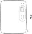
- FIG. 2shows an example illustration of a rear view of the network extender.
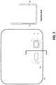
- FIG. 3shows an example illustration of a cross-sectional side view of the network extender.
- FIG. 4shows an example illustration of a front perspective view of a power module.
- FIG. 5shows an example illustration of a rear view of a power module.
- FIG. 6shows an example illustration of a top view of a power module.
- FIG. 7shows an example illustration of a left side view of a power module.
- FIG. 8shows an example illustration of a right side view of a power module.
- FIG. 9shows an example illustration of a bottom view of a power module.
- FIG. 10shows an example illustration of a front view of a power module.
- FIG. 11shows an example illustration of a power module coupled to a network extender.
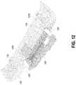
- FIG. 12shows an example illustration of a cut-away of a power module coupled to a network extender.
- FIG. 13shows an example illustration of a power module coupled to a network extender using an alternative connection mechanism.
- FIG. 14shows an example illustration of a power module coupled to a network extender, wherein the power module is secured by a sliding clip.
- FIG. 15shows an example illustration of a cut-away of a power module connected to a network extender by way of an alternative connection mechanism.
- FIG. 16shows an example illustration of a cut-away view showing a sliding clip in a disengaged position with respect to an extension of a power module.
- a power modulemay be designed such that the power module may be attached to and detached from a network extender.
- the power modulemay include one or more power connectors that are specific to one or more countries/regions.
- the power modulemay include one or more other interfaces (e.g., Ethernet port, etc.).
- the power modulemay include a power connector and a male local area network connector on a first surface.
- the power modulemay include a local area network port on a second surface, wherein the local area network port is conductively connected to the male local area network connector via a local area network port access.
- FIG. 1shows an example illustration of a rear perspective view of a network extender 105 .
- the network extender 105is shown in an upright position.
- the network extender 105may be supported by a horizontal surface or may be mounted to a vertical surface.
- a bottom surface of the network extender 105may include one or more legs or other surfaces configured to provide stability to the network extender 105 when the network extender 105 is supported in an upright position by a horizontal surface.
- the front surface of the network extender 105may include one or more status lights (e.g., LEDs) and one or more buttons (e.g., a WPS (Wi-Fi protected setup) button).
- the side surface of the network extender 105may include a power switch and a recessed reset button.
- the network extender 105may include a power port 110 configured to accept a power connector and a LAN (local area network) port 115 configured to accept a LAN connector (e.g., an Ethernet port configured to accept an Ethernet connector).
- the power port 110 and LAN port 115may be located within a connector section 120 of the network extender 105 .
- the connector section 120may be a recessed section of a rear surface 125 of the network extender 105 .
- the rear surface 125 of the network extender 105may include one or more light indicators 130 (e.g., light emitting diodes (LEDs)) to provide an indication of a current status of the network extender 105 (e.g., status of the LAN to which the network extender 105 is connected).
- LEDslight emitting diodes
- one or more clip openings 135may be located on the rear surface of the network extender 105 .
- FIG. 2shows an example illustration of a rear view of the network extender 105 .
- FIG. 3shows an example illustration of a cross-sectional side view of the network extender 105 .
- the cross-section A-Ashows the recessed connector section 120 of the network extender 105 .
- FIG. 4shows an example illustration of a front perspective view of a power module 400 .
- the power module 400may include a power adapter 405 (e.g., AC connector) that corresponds with a certain region/country-specific power outlet.
- the power module 400may include a local area network port 410 (e.g., an Ethernet port) at a first surface (e.g., the bottom of the power module 400 ) and a male local area network connector 415 (e.g., a male Ethernet connector) on a second surface (e.g., the front surface of the power module 400 ).
- a local area network port 410e.g., an Ethernet port
- a male local area network connector 415e.g., a male Ethernet connector
- the power module 400may include a power connector 420 .
- the power connector 420may be on the second surface (e.g., the front surface of the power module 400 ).
- the power module 400may include a flexible clip 425 at each end.
- Each flexible clip 425may include a finger grip form 430 .
- a flexible clip 425may be moved toward the center of the power module 400 in response to a force being applied to a corresponding finger grip form 430 .
- the local area network port 410 on the bottom of the power module 400may be conductively connected to the male local area network connector 415 via a ninety-degree local area network port access 435 (the ninety-degree local area network port access 435 is shown in broken lines).
- the ninety-degree local area network port accessmay pass from the bottom of the power module 400 to a front surface of the power module 400 .
- the ninety-degree local area network port accessmay be an Ethernet port access.
- local area network port 410may be an Ethernet port and that the male local area network connector 415 may be a male Ethernet connector.
- FIG. 5shows an example illustration of a rear view of a power module 400 .
- FIG. 6shows an example illustration of a top view of a power module 400 .
- FIG. 7shows an example illustration of a left side view of a power module 400 .
- FIG. 8shows an example illustration of a right side view of a power module 400 .
- FIG. 9shows an example illustration of a bottom view of a power module 400 .
- FIG. 10shows an example illustration of a front view of a power module 400 .
- FIG. 11shows an example illustration of a power module 400 that may be coupled to a network extender 105 .
- the power module 400may be coupled to the network extender 105 , and the power adapter 405 of the power module 400 may be plugged into a power outlet 1105 .
- the power module 400may include a power adapter 405 (e.g., AC connector) that corresponds with a certain region/country-specific power outlet.
- One or more ports or connectors of the network extender 105e.g., a power port 110 of FIG. 1 , a LAN port 115 of FIG.
- the network extender 105is shown as being mounted to a vertical surface (e.g., through a connection to the power outlet 1105 ) and in an upright position.
- a ninety-degree local area network port accessmay pass from the bottom of the power module 400 to a front surface of the power module 400 .
- the power module 400may include a local area network port (e.g., local area network port 410 of FIG. 4 ) at the bottom of the power module 400 and a local area network connector (e.g., a male local area network connector 415 ) on the front surface of the power module 400 .
- a local area network cord 1110e.g., an Ethernet cord
- the male local area network connector of the power module 400may be inserted into a local area network port located on the network extender 105 .
- the local area network port on the bottom of the power module 400may be conductively connected to the male local area network connector on the front surface of the power module 400 .
- the power module 400may include a power connector (e.g., a power connector 420 ) and a local area network connector (e.g., a male local area network connector 415 ) on the front surface of the power module 400 .
- the power connector and local area network connector of the power module 400may be spaced according to a spacing of a power port (e.g., a power port 110 ) and local area network port (e.g., a LAN port 115 ) on the network extender 105 .
- the power connector and local area network connectormay be positioned on the front surface of the power module 400 such that the power connector mates with the power port of the network extender 105 and the local area network connector mates with the local area network port of the network extender 105 when the power module 400 is coupled with the network extender 105 .
- the power module 400may include a flexible clip 425 at each end.
- the power module 400may be inserted into a recessed portion (e.g., connector section 120 of FIG. 1 ) of the network extender 105 such that each flexible clip 425 is inserted into a corresponding clip opening (e.g., clip opening 135 of FIG. 1 ) of the network extender 105 .
- Each flexible clip 425may include a finger grip form 430 . Pressing and depressing the finger grip form 430 may act to engage/disengage a hook at an opposing end of the corresponding flexible clip 425 to/from an interior surface of the clip openings (e.g., clip opening 135 ) located on the rear surface of the network extender 105 .
- the power module 400may be coupled to the network extender 105 in order to mount the network extender 105 to a vertical surface by plugging the power module 400 into the power outlet 1105 .
- the power module 400may be removed from the network extender 105 in order to stand the network extender 105 in an upright position on a horizontal surface.
- each finger grip form 430may be depressed, thereby disengaging one or more hooks of each flexible clip 425 from the interior of one or more clip openings (e.g., clip opening 135 ) of the network extender 105 , and the power module 400 may be disconnected from the network extender 105 .
- the power module 400is described herein as being coupled to a network extender 105 , it should be understood that the power module 400 may be coupled to any device (e.g., customer premise equipment (CPE) device) having a power port and/or local area network port.
- CPEcustomer premise equipment
- FIG. 12shows an example illustration of a cut-away of a power module 400 coupled to a network extender 105 .
- each flexible clip 425may be in an engaged position.
- each respective flexible clip 425may be locked securely into place when a ramp 1205 of the respective flexible clip 425 passes through a corresponding clip opening 135 .
- Each flexible clip 425may be designed to resist deflection (e.g., each flexible clip 425 may be nylon filled to resist the force of pulling the network extender 105 away from an AC outlet).
- FIG. 13shows an example illustration of a power module 400 that may be coupled to a network extender 105 using an alternative connection mechanism.
- the network extender 105may include a sliding clip 1305 that may be moved to hold the power module 400 in place.
- two clip openings 135may be located on the rear surface 125 of the network extender 105 .
- the two clip openings 135may be dimensioned and positioned so that each clip opening 135 may accept a flexible clip 425 associated with the power module 400 when the power module 400 is coupled to the network extender 105 .
- the power module 400may include a flexible clip 425 at each end.
- the power module 400may be inserted into the recessed connector section 120 of the network extender 105 such that each flexible clip 425 is inserted into a corresponding clip opening 135 .
- Pushing and/or pulling the power module 400may act to engage/disengage a hook at an opposing end of a flexible clip 425 to/from an interior surface of the corresponding clip opening 135 .
- the power module 400may include an extension 1310 and the rear surface 125 of the network extender 105 may include a sliding clip 1305 .
- the sliding clip 1305may be slid up/down in a vertical direction when the network extender is in an upright position.
- the sliding clip 1305may be slid down to cover the extension 1310 of the power module 400 , thereby securing the power module 400 to the network extender 105 .
- FIG. 14shows an example illustration of a power module 400 coupled to a network extender 105 , wherein the power module 400 is secured by a sliding clip 1305 .
- the sliding clip 1305may be positioned to cover an extension (e.g., extension 1310 of FIG. 13 ) of the power module 400 .
- the sliding clip 1305is shown in an engaged position with respect to an extension of the power module 400 .
- the sliding clip 1305may be lowered such that the extension of the power module 400 is covered, thereby securing the power module 400 against the network extender 105 .
- FIG. 15shows an example illustration of a cut-away of a power module 400 connected to a network extender 105 by way of an alternative connection mechanism.
- one or more flexible clips 425 of the power module 400may be engaged.
- a tab 1505 of each flexible clip 425 and an interior edge 1510 of each clip opening 135may be rounded so that upon insertion of the flexible clips 425 into the clip openings 135 , only a soft locking occurs.
- the tabs 1505may hold the flexible clips 425 in position with respect to the interior surface of the clip openings 135 .
- the power module 400may include one or more flared grips 1515 to allow a user to firmly and securely grip the power module 400 when engaging and/or disengaging the power module 400 from the network extender 105 .
- the flexible clips 425 of the power module 400may be disengaged from the network extender 105 .
- the flexible clips 425may deflect utilizing the spring of the material (e.g., plastic) rather than a separate part.
- a sliding clipe.g., 1305 of FIG. 13
- the power module 400may be inserted into or removed from the network extender 105 without any additional action of pressing/depressing the flexible clips 425 .
- FIG. 16shows an example illustration of a cut-away view showing a sliding clip 1305 in a disengaged position with respect to an extension 1310 of a power module 400 .
- the sliding clip 1305may be raised such that the extension 1310 of the power module 400 is uncovered, thereby allowing the power module 400 to be easily removed from a network extender (e.g., network extender 105 of FIG. 1 ).
- the surface of the sliding clip 1305may include a finger grip 1605 (e.g., depression and/or grooves) to provide a gripping surface.
Landscapes
- Connector Housings Or Holding Contact Members (AREA)
- Details Of Connecting Devices For Male And Female Coupling (AREA)
- Coupling Device And Connection With Printed Circuit (AREA)
Abstract
Description
Claims (11)
Priority Applications (5)
| Application Number | Priority Date | Filing Date | Title |
|---|---|---|---|
| CA3085362ACA3085362A1 (en) | 2017-12-20 | 2018-12-20 | Wall-mounted network extender and adapter |
| US16/227,280US10594099B2 (en) | 2017-12-20 | 2018-12-20 | Wall-mounted network extender and adapter |
| MX2020006330AMX2020006330A (en) | 2017-12-20 | 2018-12-20 | Wall-mounted network extender and adapter. |
| PCT/US2018/066759WO2019126475A1 (en) | 2017-12-20 | 2018-12-20 | Wall-mounted network extender and adapter |
| US16/782,651US11289862B2 (en) | 2017-12-20 | 2020-02-05 | Wall-mounted network extender and adapter |
Applications Claiming Priority (2)
| Application Number | Priority Date | Filing Date | Title |
|---|---|---|---|
| US201762607957P | 2017-12-20 | 2017-12-20 | |
| US16/227,280US10594099B2 (en) | 2017-12-20 | 2018-12-20 | Wall-mounted network extender and adapter |
Related Child Applications (1)
| Application Number | Title | Priority Date | Filing Date |
|---|---|---|---|
| US16/782,651ContinuationUS11289862B2 (en) | 2017-12-20 | 2020-02-05 | Wall-mounted network extender and adapter |
Publications (2)
| Publication Number | Publication Date |
|---|---|
| US20190207350A1 US20190207350A1 (en) | 2019-07-04 |
| US10594099B2true US10594099B2 (en) | 2020-03-17 |
Family
ID=65024095
Family Applications (2)
| Application Number | Title | Priority Date | Filing Date |
|---|---|---|---|
| US16/227,280ActiveUS10594099B2 (en) | 2017-12-20 | 2018-12-20 | Wall-mounted network extender and adapter |
| US16/782,651ActiveUS11289862B2 (en) | 2017-12-20 | 2020-02-05 | Wall-mounted network extender and adapter |
Family Applications After (1)
| Application Number | Title | Priority Date | Filing Date |
|---|---|---|---|
| US16/782,651ActiveUS11289862B2 (en) | 2017-12-20 | 2020-02-05 | Wall-mounted network extender and adapter |
Country Status (4)
| Country | Link |
|---|---|
| US (2) | US10594099B2 (en) |
| CA (1) | CA3085362A1 (en) |
| MX (1) | MX2020006330A (en) |
| WO (1) | WO2019126475A1 (en) |
Cited By (1)
| Publication number | Priority date | Publication date | Assignee | Title |
|---|---|---|---|---|
| US20240413599A1 (en)* | 2023-06-12 | 2024-12-12 | Dell Products L.P. | Junction connector for modular dongle assembly |
Families Citing this family (1)
| Publication number | Priority date | Publication date | Assignee | Title |
|---|---|---|---|---|
| US20220086025A1 (en)* | 2020-09-14 | 2022-03-17 | Microsoft Technology Licensing, Llc | Flexible network interfaces as a framework for a network appliance |
Citations (8)
| Publication number | Priority date | Publication date | Assignee | Title |
|---|---|---|---|---|
| US5466165A (en)* | 1994-01-06 | 1995-11-14 | Woods Industries, Inc. | Portable outlet adapter |
| JPH088952A (en) | 1994-06-17 | 1996-01-12 | Matsushita Electric Works Ltd | Hub |
| US6747859B2 (en)* | 2000-07-11 | 2004-06-08 | Easyplug Inc. | Modular power line network adapter |
| US20090109638A1 (en) | 2007-10-29 | 2009-04-30 | Belkin International, Inc. | Modular Powerline Adapters and Methods of Use |
| DE202012104390U1 (en) | 2012-01-09 | 2013-01-15 | Carry Technology Co., Ltd. | Network device with an interface for sharing power |
| CN203481569U (en) | 2013-08-27 | 2014-03-12 | 东莞欧陆电子有限公司 | Multifunctional thin adapter for travel |
| EP2928027A1 (en) | 2014-03-31 | 2015-10-07 | A.S.A. Plastici Azienda Stampaggio Articoli Plastici S.R.L. | Multifunctional multiple socket |
| CN106299929A (en) | 2016-09-14 | 2017-01-04 | 深圳幂客智能有限公司 | A kind of Internet of Things connecting line, cable and socket |
Family Cites Families (4)
| Publication number | Priority date | Publication date | Assignee | Title |
|---|---|---|---|---|
| US7519000B2 (en)* | 2002-01-30 | 2009-04-14 | Panduit Corp. | Systems and methods for managing a network |
| US20040223180A1 (en)* | 2003-05-08 | 2004-11-11 | Transact Technologies Incorporated | Transactional printer with wireless communication to host |
| IL157787A (en)* | 2003-09-07 | 2010-12-30 | Mosaid Technologies Inc | Modular outlet for data communications network |
| US9726361B1 (en)* | 2016-02-09 | 2017-08-08 | Michael W. May | Networked LED lighting system |
- 2018
- 2018-12-20USUS16/227,280patent/US10594099B2/enactiveActive
- 2018-12-20WOPCT/US2018/066759patent/WO2019126475A1/ennot_activeCeased
- 2018-12-20MXMX2020006330Apatent/MX2020006330A/enunknown
- 2018-12-20CACA3085362Apatent/CA3085362A1/enactivePending
- 2020
- 2020-02-05USUS16/782,651patent/US11289862B2/enactiveActive
Patent Citations (8)
| Publication number | Priority date | Publication date | Assignee | Title |
|---|---|---|---|---|
| US5466165A (en)* | 1994-01-06 | 1995-11-14 | Woods Industries, Inc. | Portable outlet adapter |
| JPH088952A (en) | 1994-06-17 | 1996-01-12 | Matsushita Electric Works Ltd | Hub |
| US6747859B2 (en)* | 2000-07-11 | 2004-06-08 | Easyplug Inc. | Modular power line network adapter |
| US20090109638A1 (en) | 2007-10-29 | 2009-04-30 | Belkin International, Inc. | Modular Powerline Adapters and Methods of Use |
| DE202012104390U1 (en) | 2012-01-09 | 2013-01-15 | Carry Technology Co., Ltd. | Network device with an interface for sharing power |
| CN203481569U (en) | 2013-08-27 | 2014-03-12 | 东莞欧陆电子有限公司 | Multifunctional thin adapter for travel |
| EP2928027A1 (en) | 2014-03-31 | 2015-10-07 | A.S.A. Plastici Azienda Stampaggio Articoli Plastici S.R.L. | Multifunctional multiple socket |
| CN106299929A (en) | 2016-09-14 | 2017-01-04 | 深圳幂客智能有限公司 | A kind of Internet of Things connecting line, cable and socket |
Non-Patent Citations (1)
| Title |
|---|
| PCT International Search Report & Written Opinion, Re: Application No. PCT/US2018/066759, dated Feb. 28, 2019. |
Cited By (1)
| Publication number | Priority date | Publication date | Assignee | Title |
|---|---|---|---|---|
| US20240413599A1 (en)* | 2023-06-12 | 2024-12-12 | Dell Products L.P. | Junction connector for modular dongle assembly |
Also Published As
| Publication number | Publication date |
|---|---|
| MX2020006330A (en) | 2020-08-27 |
| US20200176938A1 (en) | 2020-06-04 |
| US20190207350A1 (en) | 2019-07-04 |
| CA3085362A1 (en) | 2019-06-27 |
| WO2019126475A1 (en) | 2019-06-27 |
| US11289862B2 (en) | 2022-03-29 |
Similar Documents
| Publication | Publication Date | Title |
|---|---|---|
| US11289862B2 (en) | Wall-mounted network extender and adapter | |
| US9148006B2 (en) | Interchangeable base system | |
| US8152125B2 (en) | Methods and apparatus for mounting devices | |
| US7687716B2 (en) | Adjustable cable support bracket for an electrical component | |
| US6832921B1 (en) | Electrical safety outlet and power cord | |
| US7014493B1 (en) | Retaining socket for electrical outlets | |
| US8598453B2 (en) | Power strip hanging device and structure | |
| US20070164178A1 (en) | Mounting receptacle with interchangeable hub | |
| CN101843416A (en) | Height adjustment device of children's dining chair and the children's dining chair | |
| US6485327B1 (en) | Electrical extension cord with capability for multi-positional fixed mounting | |
| US8018725B2 (en) | Cable support bracket for an electrical component | |
| WO2009014920A2 (en) | Behind c-channel shelf attachment mechanism | |
| US20050280984A1 (en) | Tablet PC and base member coupling arrangement | |
| US9287661B2 (en) | Clip and latch substitution device for modular plugs | |
| EP3701600A1 (en) | Wall-mounted network extender and adapter | |
| US20110237114A1 (en) | Cord hook device | |
| CN206893936U (en) | Socket box and the desk using the socket box | |
| JP2006523011A (en) | A housing for accommodating a printed wiring board in which a mounting portion of the printed wiring board forms at least a part of a communication system | |
| US7341480B2 (en) | Releasable latch assemblies | |
| US20070062735A1 (en) | Removable electrical outlet protective cover | |
| US20050244217A1 (en) | Test instrument module latch system and method | |
| US20250017397A1 (en) | Connector for frame | |
| JP6622111B2 (en) | Box for information distribution board | |
| LT5554B (en) | Medical devices fastening system | |
| KR20180002104U (en) | Option board and electronic device including the same |
Legal Events
| Date | Code | Title | Description |
|---|---|---|---|
| FEPP | Fee payment procedure | Free format text:ENTITY STATUS SET TO UNDISCOUNTED (ORIGINAL EVENT CODE: BIG.); ENTITY STATUS OF PATENT OWNER: LARGE ENTITY | |
| AS | Assignment | Owner name:ARRIS ENTERPRISES LLC, GEORGIA Free format text:ASSIGNMENT OF ASSIGNORS INTEREST;ASSIGNORS:HARLEY, PAUL JOSEPH;HUANG, CHIEN-CHENG;WU, XUE-HONG;AND OTHERS;SIGNING DATES FROM 20190315 TO 20190320;REEL/FRAME:048690/0323 | |
| AS | Assignment | Owner name:ARRIS ENTERPRISES LLC, GEORGIA Free format text:CHANGE OF NAME;ASSIGNOR:ARRIS ENTERPRISES, INC.;REEL/FRAME:049586/0470 Effective date:20151231 | |
| STPP | Information on status: patent application and granting procedure in general | Free format text:NON FINAL ACTION MAILED | |
| AS | Assignment | Owner name:WILMINGTON TRUST, NATIONAL ASSOCIATION, AS COLLATE Free format text:PATENT SECURITY AGREEMENT;ASSIGNOR:ARRIS ENTERPRISES LLC;REEL/FRAME:049820/0495 Effective date:20190404 Owner name:JPMORGAN CHASE BANK, N.A., NEW YORK Free format text:TERM LOAN SECURITY AGREEMENT;ASSIGNORS:COMMSCOPE, INC. OF NORTH CAROLINA;COMMSCOPE TECHNOLOGIES LLC;ARRIS ENTERPRISES LLC;AND OTHERS;REEL/FRAME:049905/0504 Effective date:20190404 Owner name:JPMORGAN CHASE BANK, N.A., NEW YORK Free format text:ABL SECURITY AGREEMENT;ASSIGNORS:COMMSCOPE, INC. OF NORTH CAROLINA;COMMSCOPE TECHNOLOGIES LLC;ARRIS ENTERPRISES LLC;AND OTHERS;REEL/FRAME:049892/0396 Effective date:20190404 Owner name:WILMINGTON TRUST, NATIONAL ASSOCIATION, AS COLLATERAL AGENT, CONNECTICUT Free format text:PATENT SECURITY AGREEMENT;ASSIGNOR:ARRIS ENTERPRISES LLC;REEL/FRAME:049820/0495 Effective date:20190404 | |
| STPP | Information on status: patent application and granting procedure in general | Free format text:RESPONSE TO NON-FINAL OFFICE ACTION ENTERED AND FORWARDED TO EXAMINER | |
| STPP | Information on status: patent application and granting procedure in general | Free format text:NOTICE OF ALLOWANCE MAILED -- APPLICATION RECEIVED IN OFFICE OF PUBLICATIONS | |
| STPP | Information on status: patent application and granting procedure in general | Free format text:PUBLICATIONS -- ISSUE FEE PAYMENT VERIFIED | |
| STCF | Information on status: patent grant | Free format text:PATENTED CASE | |
| AS | Assignment | Owner name:WILMINGTON TRUST, DELAWARE Free format text:SECURITY INTEREST;ASSIGNORS:ARRIS SOLUTIONS, INC.;ARRIS ENTERPRISES LLC;COMMSCOPE TECHNOLOGIES LLC;AND OTHERS;REEL/FRAME:060752/0001 Effective date:20211115 | |
| MAFP | Maintenance fee payment | Free format text:PAYMENT OF MAINTENANCE FEE, 4TH YEAR, LARGE ENTITY (ORIGINAL EVENT CODE: M1551); ENTITY STATUS OF PATENT OWNER: LARGE ENTITY Year of fee payment:4 | |
| AS | Assignment | Owner name:APOLLO ADMINISTRATIVE AGENCY LLC, NEW YORK Free format text:SECURITY INTEREST;ASSIGNORS:ARRIS ENTERPRISES LLC;COMMSCOPE TECHNOLOGIES LLC;COMMSCOPE INC., OF NORTH CAROLINA;AND OTHERS;REEL/FRAME:069889/0114 Effective date:20241217 | |
| AS | Assignment | Owner name:RUCKUS WIRELESS, LLC (F/K/A RUCKUS WIRELESS, INC.), NORTH CAROLINA Free format text:RELEASE OF SECURITY INTEREST AT REEL/FRAME 049905/0504;ASSIGNOR:JPMORGAN CHASE BANK, N.A., AS COLLATERAL AGENT;REEL/FRAME:071477/0255 Effective date:20241217 Owner name:COMMSCOPE TECHNOLOGIES LLC, NORTH CAROLINA Free format text:RELEASE OF SECURITY INTEREST AT REEL/FRAME 049905/0504;ASSIGNOR:JPMORGAN CHASE BANK, N.A., AS COLLATERAL AGENT;REEL/FRAME:071477/0255 Effective date:20241217 Owner name:COMMSCOPE, INC. OF NORTH CAROLINA, NORTH CAROLINA Free format text:RELEASE OF SECURITY INTEREST AT REEL/FRAME 049905/0504;ASSIGNOR:JPMORGAN CHASE BANK, N.A., AS COLLATERAL AGENT;REEL/FRAME:071477/0255 Effective date:20241217 Owner name:ARRIS SOLUTIONS, INC., NORTH CAROLINA Free format text:RELEASE OF SECURITY INTEREST AT REEL/FRAME 049905/0504;ASSIGNOR:JPMORGAN CHASE BANK, N.A., AS COLLATERAL AGENT;REEL/FRAME:071477/0255 Effective date:20241217 Owner name:ARRIS TECHNOLOGY, INC., NORTH CAROLINA Free format text:RELEASE OF SECURITY INTEREST AT REEL/FRAME 049905/0504;ASSIGNOR:JPMORGAN CHASE BANK, N.A., AS COLLATERAL AGENT;REEL/FRAME:071477/0255 Effective date:20241217 Owner name:ARRIS ENTERPRISES LLC (F/K/A ARRIS ENTERPRISES, INC.), NORTH CAROLINA Free format text:RELEASE OF SECURITY INTEREST AT REEL/FRAME 049905/0504;ASSIGNOR:JPMORGAN CHASE BANK, N.A., AS COLLATERAL AGENT;REEL/FRAME:071477/0255 Effective date:20241217 |