US10592821B2 - Self-learning fault detection for HVAC systems - Google Patents
Self-learning fault detection for HVAC systemsDownload PDFInfo
- Publication number
- US10592821B2 US10592821B2US15/186,756US201615186756AUS10592821B2US 10592821 B2US10592821 B2US 10592821B2US 201615186756 AUS201615186756 AUS 201615186756AUS 10592821 B2US10592821 B2US 10592821B2
- Authority
- US
- United States
- Prior art keywords
- fault
- hvac
- parameters
- fault detection
- accordance
- Prior art date
- Legal status (The legal status is an assumption and is not a legal conclusion. Google has not performed a legal analysis and makes no representation as to the accuracy of the status listed.)
- Active, expires
Links
Images


Classifications
- G—PHYSICS
- G06—COMPUTING OR CALCULATING; COUNTING
- G06F—ELECTRIC DIGITAL DATA PROCESSING
- G06F11/00—Error detection; Error correction; Monitoring
- G06F11/07—Responding to the occurrence of a fault, e.g. fault tolerance
- G06F11/16—Error detection or correction of the data by redundancy in hardware
- G—PHYSICS
- G06—COMPUTING OR CALCULATING; COUNTING
- G06N—COMPUTING ARRANGEMENTS BASED ON SPECIFIC COMPUTATIONAL MODELS
- G06N20/00—Machine learning
- F—MECHANICAL ENGINEERING; LIGHTING; HEATING; WEAPONS; BLASTING
- F24—HEATING; RANGES; VENTILATING
- F24F—AIR-CONDITIONING; AIR-HUMIDIFICATION; VENTILATION; USE OF AIR CURRENTS FOR SCREENING
- F24F11/00—Control or safety arrangements
- F24F11/30—Control or safety arrangements for purposes related to the operation of the system, e.g. for safety or monitoring
- F24F11/32—Responding to malfunctions or emergencies
- F24F11/38—Failure diagnosis
- F—MECHANICAL ENGINEERING; LIGHTING; HEATING; WEAPONS; BLASTING
- F24—HEATING; RANGES; VENTILATING
- F24F—AIR-CONDITIONING; AIR-HUMIDIFICATION; VENTILATION; USE OF AIR CURRENTS FOR SCREENING
- F24F11/00—Control or safety arrangements
- F24F11/50—Control or safety arrangements characterised by user interfaces or communication
- F24F11/52—Indication arrangements, e.g. displays
- F—MECHANICAL ENGINEERING; LIGHTING; HEATING; WEAPONS; BLASTING
- F24—HEATING; RANGES; VENTILATING
- F24F—AIR-CONDITIONING; AIR-HUMIDIFICATION; VENTILATION; USE OF AIR CURRENTS FOR SCREENING
- F24F11/00—Control or safety arrangements
- F24F11/50—Control or safety arrangements characterised by user interfaces or communication
- F24F11/56—Remote control
- F24F11/58—Remote control using Internet communication
- F—MECHANICAL ENGINEERING; LIGHTING; HEATING; WEAPONS; BLASTING
- F24—HEATING; RANGES; VENTILATING
- F24F—AIR-CONDITIONING; AIR-HUMIDIFICATION; VENTILATION; USE OF AIR CURRENTS FOR SCREENING
- F24F11/00—Control or safety arrangements
- F24F11/62—Control or safety arrangements characterised by the type of control or by internal processing, e.g. using fuzzy logic, adaptive control or estimation of values
- F24F11/63—Electronic processing
- G—PHYSICS
- G05—CONTROLLING; REGULATING
- G05B—CONTROL OR REGULATING SYSTEMS IN GENERAL; FUNCTIONAL ELEMENTS OF SUCH SYSTEMS; MONITORING OR TESTING ARRANGEMENTS FOR SUCH SYSTEMS OR ELEMENTS
- G05B13/00—Adaptive control systems, i.e. systems automatically adjusting themselves to have a performance which is optimum according to some preassigned criterion
- G05B13/02—Adaptive control systems, i.e. systems automatically adjusting themselves to have a performance which is optimum according to some preassigned criterion electric
- G05B13/0265—Adaptive control systems, i.e. systems automatically adjusting themselves to have a performance which is optimum according to some preassigned criterion electric the criterion being a learning criterion
- G—PHYSICS
- G05—CONTROLLING; REGULATING
- G05B—CONTROL OR REGULATING SYSTEMS IN GENERAL; FUNCTIONAL ELEMENTS OF SUCH SYSTEMS; MONITORING OR TESTING ARRANGEMENTS FOR SUCH SYSTEMS OR ELEMENTS
- G05B23/00—Testing or monitoring of control systems or parts thereof
- G05B23/02—Electric testing or monitoring
- G05B23/0205—Electric testing or monitoring by means of a monitoring system capable of detecting and responding to faults
- G05B23/0259—Electric testing or monitoring by means of a monitoring system capable of detecting and responding to faults characterized by the response to fault detection
- G05B23/0262—Confirmation of fault detection, e.g. extra checks to confirm that a failure has indeed occurred
- F—MECHANICAL ENGINEERING; LIGHTING; HEATING; WEAPONS; BLASTING
- F24—HEATING; RANGES; VENTILATING
- F24F—AIR-CONDITIONING; AIR-HUMIDIFICATION; VENTILATION; USE OF AIR CURRENTS FOR SCREENING
- F24F11/00—Control or safety arrangements
- F24F11/30—Control or safety arrangements for purposes related to the operation of the system, e.g. for safety or monitoring
- F24F11/32—Responding to malfunctions or emergencies
- F—MECHANICAL ENGINEERING; LIGHTING; HEATING; WEAPONS; BLASTING
- F24—HEATING; RANGES; VENTILATING
- F24F—AIR-CONDITIONING; AIR-HUMIDIFICATION; VENTILATION; USE OF AIR CURRENTS FOR SCREENING
- F24F11/00—Control or safety arrangements
- F24F11/62—Control or safety arrangements characterised by the type of control or by internal processing, e.g. using fuzzy logic, adaptive control or estimation of values
- F24F11/63—Electronic processing
- F24F11/64—Electronic processing using pre-stored data
Definitions
- the present disclosureis directed to improving the reliability of HVAC systems, and in particular, to systems, apparatus, and methods for monitoring HVAC system operating characteristics which provide improved diagnosis of system malfunctions.
- HVACheating, ventilation and air conditioning
- FDDfault detection and diagnosis
- Known techniques for fault detectioncommonly employ algorithms which attempt to identify faults by relating anomalies seen in measured performance parameters to an underlying cause. Such techniques rely upon assumptions about the expected performance parameters, e.g., target operating ranges, tolerances, thresholds, and so forth, as they relate to the operational health of various components of the HVAC system.
- HVAC fault detection systemwhich provides improved fault detection for a wider range of HVAC system configurations would be a welcome advance.
- the present disclosureis directed to an HVAC fault detection method.
- the methodincludes receiving, at a processor, signals indicative of sensed HVAC system operating parameters from a data gathering device of an HVAC system; identifying which of the plurality of sensed HVAC system operating parameters exceeds a parameter threshold to determine a set of error parameters and determining, from the set of error parameters, a potential fault and a corresponding fault threshold.
- Each error parameteris multiplied by a predetermined weighting factor to generate a weighted error parameter, and the weighted error parameters are summed to generate a summed value.
- the potential faultis confirmed to be a detected fault if the summed value exceeds the fault threshold.
- the resultsare stored in a database as a dataset including a set of optimization parameters comprising the parameter thresholds, the predetermined weighting factors, and the fault threshold.
- the set of optimization parametersfurther includes parameters such as the sensed HVAC system operating parameters, the set of error parameters, and the detected fault.
- the disclosed methodincludes transmitting a fault message indicative of the identified fault.
- an initial set of parameter thresholdsis provided.
- noise reductionis performed on at least one of the received signals.
- an HVAC system operating parametermay be normalized to fall within a standardized range.
- the methodincludes receiving feedback data indicative of whether the detected fault is an actual fault; and storing, in the dataset, the feedback data.
- the disclosed methodincludes selecting, from the database, a plurality of datasets having a common detected fault; identifying, within the selected plurality of datasets, each unique set of optimization parameters; obtaining, for each of the selected plurality of datasets, a weighted total sum of the optimization parameters; determining a z-score for each set of weighted total sums of the optimization parameters; identifying the set of optimization parameters having the most negative z-score; and utilizing the set of optimization parameters having the most negative z-score as predetermined weighting factors.
- the methodincludes comparing the z-score of the set of optimization parameters having the most negative z-score to a threshold and, optionally, transmitting an alert and/or inhibiting the detection of the common detected fault in response to the comparing.
- the methodincludes determining a mean of each set of weighted total sums of the optimization parameters, and determining a standard deviation of each set of weighted total sums of the optimization parameters.
- the present disclosureis directed to an HVAC fault detection system.
- the systemincludes a data gathering module configured for receiving HVAC system operating parameters from components of an HVAC system and for transmitting the received HVAC system operating parameters to a recipient device, such as, without limitation, a data analysis module included within a network-connected server computer.
- the systemincludes a data analysis module configured for receiving HVAC system operating parameters from the data gathering module.
- the data analysis moduleincludes a database configured for storing received HVAC system operating parameters, a processor operatively coupled to the database, and a memory operatively coupled to the processor.
- the memoryincludes a set of executable instructions which, when executed by the processor, cause the processor to identify which of the plurality of sensed HVAC system operating parameters exceeds a parameter threshold to determine a set of error parameters; determine, from the set of error parameters, a potential fault and a corresponding fault threshold; multiply each error parameter by a predetermined weighting factor to generate a set of weighted error parameters; sum the set of weighted error parameters to generate a summed value; confirm that the potential fault is a detected fault in response to a determination that the summed value exceeds the fault threshold; and store, in the database, a dataset including a set of optimization parameters comprising the parameter thresholds, the predetermined weighting factors, and the fault threshold.
- the data analysis moduleincludes memory having executable instructions that further cause the processor to cause a transmission of a fault message indicative of the identified fault.
- the disclosed systemincludes memory having executable instructions that further cause the processor to normalize an HVAC system operating parameter to fall within a standardized range.
- the data analysis moduleincludes memory having executable instructions that further cause the processor to identify, within the selected plurality of datasets, each unique set of optimization parameters; obtain, for each of the selected plurality of datasets, a weighted total sum of the optimization parameters; determine a z-score for each set of weighted total sums of the optimization parameters; identify the set of optimization parameters having the most negative z-score; and utilize the identified set of optimization parameters having the most negative z-score as predetermined weighting factors.
- the data analysis moduleincludes memory having executable instructions that further cause the processor to compare the z-score of the set of optimization parameters having the most negative z-score to a threshold.
- FIG. 1Ais a schematic block diagram representation of an embodiment of a system of the present disclosure
- FIG. 1Bis a schematic block diagram representation of an embodiment of a heating, ventilation and air conditioning system that is communicably coupled to the embodiment of the system of FIG. 1A ;
- FIG. 2is a block diagram representation of data flow in an embodiment of a system of the present disclosure
- FIG. 3Ais a flowchart illustrating a method of fault detection and diagnosis in accordance with an embodiment of the present disclosure
- FIG. 3Bis a flowchart illustrating another method of fault detection and diagnosis in accordance with an embodiment of the present disclosure
- FIG. 4is a state diagram depicting logic conditions for fault diagnosis in accordance with an embodiment of the present disclosure
- FIG. 5is a flowchart illustrating a method of fault detection and diagnosis optimization in accordance with an embodiment of the present disclosure.
- FIG. 6is a flowchart illustrating another method of fault detection and diagnosis optimization in accordance with an embodiment of the present disclosure.
- the disclosed methodfurther optimizes the fault detection and identification to provide increasingly consistent and reliable performance.
- the disclosed methodsprovide advantages over prior-art techniques for identifying faults from HVAC operation data, particularly when many datasets and/or many different HVAC systems are being analyzed. Many different HVAC systems may be monitored using the same set of optimization parameters.
- the disclosed methodsperform numerical and statistical processing of measurements and information taken from HVAC systems to diagnose faults.
- the disclosed methodsinclude the normalization of incoming data and/or logic for determining HVAC system conditions.
- a fault detection system in accordance with the present disclosureis able to provide improved fault detection accuracy over existing fault detection methods.
- the present disclosuremay be described herein in terms of functional block components, code listings, optional selections, page displays, and various processing steps. It should be appreciated that such functional blocks may be realized by any number of hardware and/or software components configured to perform the specified functions.
- the present disclosuremay employ various integrated circuit components, e.g., memory elements, processing elements, logic elements, look-up tables, and the like, which may carry out a variety of functions under the control of one or more microprocessors or other control devices.
- the hardware and/or software components for implementing one or more of the functional blocks or method stepsmay be implemented on one or more server(s) 12 accessing data from a plurality of HVAC systems 16 , or distributed between any combination of one or more server(s) 12 and a user device 14 operably connected to the one or more server(s) 12 .
- the user devices of the present disclosuremay be mobile devices, such as a smart phone or tablet, that include a software application (app) installed therein for enabling service technicians to communicate information obtained from servicing a reported fault in an HVAC system.
- user devicesmay also include any other suitable device, including a computer, laptop, diagnostic unit (multimeter) and so on, for entry and transmission of the information via a web-based interface or a dedicated interface, for example.
- the software elements of the present disclosuremay be implemented with any programming or scripting language such as C, C++, C#, Java, COBOL, assembler, PERL, Python, PHP, Ruby, or the like, with the various algorithms being implemented with any combination of data structures, objects, processes, routines or other programming elements.
- the object code createdmay be executed by any device, on a variety of operating systems, including without limitation Apple OSX®, Apple iOS®, Google Android®, HP WebOS®, Linux, UNIX®, Microsoft Windows®, and/or Microsoft Windows Mobile®.
- the present disclosuremay be embodied as a method, a device, e.g., a server device, configured to implement the methods disclosed herein, and/or a computer program product. Accordingly, the present disclosure may take the form of an entirely software embodiment, an entirely hardware embodiment, or an embodiment combining aspects of both software and hardware. Furthermore, the present disclosure may take the form of a computer program product on a computer-readable storage medium having computer-readable program code means embodied in the storage medium. Any suitable computer-readable storage medium may be utilized, including hard disks, CD-ROM, DVD-ROM, optical storage devices, magnetic storage devices, semiconductor storage devices (e.g., flash memory, USB thumb drives) and/or the like.
- Computer program instructions embodying the present disclosuremay also be stored in a computer-readable memory that can direct a computer or other programmable data processing apparatus to function in a particular manner, such that the instructions stored in the computer-readable memory produce an article of manufacture, including instruction means, that implement the function specified in the description or flowchart block(s).
- the computer program instructionsmay also be loaded onto a computer or other programmable data processing apparatus to cause a series of operational steps to be performed on the computer or other programmable apparatus to produce a computer-implemented process such that the instructions that execute on the computer or other programmable apparatus provide steps for implementing the functions specified in the present disclosure.
- the server 12includes a processing device or devices 22 , memory including computer readable memory or storage 24 for storage of software, instructions, or executable code, which when executed by the processing device(s) 22 causes the processing device(s) 22 to perform methods or method steps of the present disclosure, which may be embodied at least in part in programming instructions 26 stored on or retrievable by the server 12 .
- components 22 , 24 and programming instructions 26 for performing the methods or method steps of the present disclosuremay be also be distributed among various devices, which may include user devices 14 , such as computers, laptops, mobile devices, phones, tablets, and so on, and may also, in embodiments, include programmable logic installed in components of the HVAC system(s) 16 .
- any databases, systems, or components of the present disclosuremay consist of any combination of databases or components at a single location or at multiple locations, wherein each database or system includes any of various suitable security features, such as firewalls, access codes, encryption, de-encryption, compression, decompression, and/or the like.
- the disclosed systems and/or methodsmay be embodied, at least in part, in application software that may be downloaded, in whole or in part, from either a public or private website or an application store (“app store”) to a mobile device.
- the disclosed system and methodmay be included in the mobile device firmware, hardware, and/or software.
- the disclosed systems and/or methodsmay be embodied, at least in part, in application software executing within a webserver to provide a web-based interface to the described functionality.
- all or part of the disclosed systems and/or methodsmay be provided as one or more callable modules, an application programming interface (e.g., an API), a source library, an object library, a plug-in or snap-in, a dynamic link library (e.g., DLL), or any software architecture capable of providing the functionality disclosed herein.
- an application programming interfacee.g., an API
- a source librarye.g., an object library
- a plug-in or snap-ine.g., a plug-in or snap-in
- a dynamic link librarye.g., DLL
- sensorsrefers collectively to both sensors and transducers as commonly used in the art, and includes sensors associated with a particular piece of equipment and/or control unit or thermostat in the HVAC system, such as a temperature sensor in a thermostat. Sensors may be located on or operably connected to certain HVAC equipment. Other sensors co-located with an HVAC system may, or may not be operably connected to HVAC equipment, but may still be used in accordance with methods of the present disclosure to analyze the data collected for detecting and diagnosing a fault in the HVAC system. Examples of sensors from which data may be collected for analysis in accordance with the present disclosure include, but are not limited to, temperature, humidity, pressure, occupancy, smoke, light, motion, security sensors, and so on.
- Data that may be acquired from sensors and/or equipmentincludes, but is not limited to, measured data readings (e.g., temperature, pressure, humidity, and so on), set point (e.g., a user-defined temperature setting), current state (e.g., an “occupied” or “unoccupied” reading from an occupancy sensor), and modes of operation (e.g., heat or cool mode of a thermostat).
- measured data readingse.g., temperature, pressure, humidity, and so on
- set pointe.g., a user-defined temperature setting
- current statee.g., an “occupied” or “unoccupied” reading from an occupancy sensor
- modes of operatione.g., heat or cool mode of a thermostat.
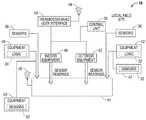
- the system 10includes a server 12 communicably coupled to a plurality of HVAC systems 16 , via the Internet 28 , for example, and specially configured to implement and execute the methods of the present disclosure.
- the server 12may also be configured to establish communications with a plurality of user devices 14 utilized by field service technicians and to send various notifications and instructions to the user devices 14 regarding any faults detected in the HVAC systems 16 in accordance with the present disclosure.
- the user devices 14are enabled to receive such notifications from the server 12 and to respond by sending information regarding the fault reported by the server 12 .
- a database 30is communicatively coupled to the server 12 for storing such information and fault data.
- the database 30may also be accessible to the service technicians' devices 14 , via the Internet 28 , for example, for storing the feedback information from the service technicians.
- an HVAC system 16 atypically includes a thermostat 18 and may include various additional control units 20 , each of which may be operable via a touch-screen panel as well as via a separate user device operated by a homeowner or system operator.
- Additional equipment in the HVAC system 16 amay include, but is not limited to, furnaces and heating equipment, air conditioners, filters, air purifiers, ventilation equipment, chillers, pumps, and air handlers.
- Equipment in the HVAC system 16 amay include both indoor 40 and outdoor equipment 42 , each of which may include sensors 32 operably connected to and/or embedded in the equipment. Some equipment may include embedded logic controllers 34 for monitoring and controlling operation.
- Additional sensors 36may be co-located with the system 16 a and may or may not be operably connected to equipment within the HVAC system 16 a.
- Such sensors 36may include, but are not limited to, occupancy, smoke, light, motion, security, humidity, pressure sensors, and so on.
- data from these sensors 32 , 36 and logic controllers 34may be collected, stored, and analyzed by the server 12 to assess current operational parameters and trends in the equipment and HVAC system 16 a, for detection and diagnosis of faults in accordance with predetermined logic conditions.
- embodiments of the HVAC system 16 amay include an electronic gathering device 44 configured to acquire data from any components associated with the system 16 , including the control unit(s) 20 , thermostat 18 , both indoor 40 and outdoor equipment 42 , and associated sensors 32 , 36 , and forward the data via the Internet 28 , for example, to the server 12 for processing.
- the electronic gathering device 44is operably connected to the server 12 for transmission of the acquired data thereto and configured for transmitting the data by any suitable connection, either wired or wireless 46 , of any appropriate type, including but not limited to WiFi, cellular, Ethernet, POTS via modem, and so on.
- the thermostat 18 of the HVAC system 16is operably connected to the data gathering device 44 , has Internet connectivity 48 , e.g., WiFi, Ethernet, and so on, and can provide the data pathway from the electronic data gathering device 44 to the central remote server 22 via the Internet 28 .
- Internet connectivity 48e.g., WiFi, Ethernet, and so on
- Any combination of the thermostat 18 and the optional electronic data gathering device 44may be used to transmit the data, including measurements of various operating parameters, from the HVAC systems 16 to the server 12 for fault detection and diagnosis.
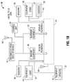
- FIG. 2illustrates a flow of data between an HVAC system 16 a, a service technician's device 14 , which may be a mobile device, and an embodiment of a server 12 in accordance with the present disclosure.
- the measured data 50 from the sensors 32 , 36 , and the like associated with the HVAC system 16 amay include continuous data 52 and event data 54 .
- the measured datais collected and transmitted to the server 12 for monitoring and analysis and may also be stored in the database 30 as a dataset 60 .
- a dataset 60includes the measured and derived parameters that are measured or calculated from measured parameters that were acquired at essentially the same point in time, or alternatively over a relatively short period of time, such that the HVAC system operating conditions are assumed to be essentially stable over that period of time.
- the data 50can include continuous measurements 52 of various operational parameters, such as, but not limited to, indoor temperature, outdoor temperature, pressure, system modes, setpoints, indoor humidity, compressor power, and so on.
- the data 50may also include discrete system operation events 54 , such as, but not limited to, calls for cooling operation, recorded events of a compressor turned on or off, changes in setpoints and/or system modes, and any other event that is triggered, for example, by a change in a system operating condition.
- the measurements of the operational parameters that are stored in the database 30therefore, can be any combination of continuously acquired data 52 and discrete, event data 54 .
- dataset 60also contains a record of the fault diagnoses, and, when available, feedback on whether or not the fault diagnosis was correct via storage of the correct fault diagnosis. Note that only some of the stored datasets might contain the correct fault diagnosis since feedback for every fault diagnosis may not be provided by service personnel in every instance.
- the server 12detects and diagnoses faults based on the measurements 50 of the operational parameters acquired from the HVAC system 16 a as described further hereinbelow. If a fault is detected, a notification of the fault with instructions 56 may be sent by the server 12 to a user device 14 accessible by a service technician. Upon correction of the fault, the service technician provides information 58 associated with the correction via the user device 14 to the server 12 , which may also be stored in the database 30 by the server 12 , or directly to the database 30 .
- the database 30may include records 60 that include all faults detected by the server 12 , along with the FDD-generated fault diagnoses, the measured dataset 50 to which each FDD diagnosis was applied, and the feedback information provided via the user device 14 , including whether or not the FDD fault diagnosis provided by the server 12 was correct.
- These records 60are used by the server 12 , or in other embodiments of the present disclosure, by a third-party server, to optimize the fault detection and diagnosis logistics as described further herein.
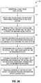
- FIG. 3Aillustrates embodiments of a method 70 of the present disclosure to detect and diagnose faults in an HVAC system 16 that is operably connected to a server 12 as described above.
- the serveridentifies, at 72 , a fault in an HVAC system 16 and determines, at 74 , one or more predicted causes of the fault based on the measurements of operational parameters 50 that are passed to the server 12 from the HVAC system 16 .
- the servertransmits, at 75 , a fault notification and instructions for correcting the fault to a service technician's mobile device.
- the server 12receives information associated with the fault at 76 from the service technician to which the fault notification was issued and also accumulates information from other service technicians based on their observations in servicing the same reported fault in past service calls.
- the information reported by the service techniciansincludes the corrective measure(s) that were implemented to successfully correct the fault.
- the informationmay also include a listing of corrective measure(s) that were implemented without success, including any measures that the service technician was originally instructed to implement to correct a suspected cause of the fault, as diagnosed by the server 12 .
- the service technicianmay determine the actual cause of the fault by making suggested changes to correct the operational error.
- the service technicianmay have attempted certain corrections that were provided in the instructions along with the fault notification, or may try other changes based on his or her prior experience.
- Such corrective measuresmay include, for example, adding a charge, removing a charge, replacing a component, correcting an airflow, or modifying a thermostat configuration in the heating, ventilation and air conditioning system.
- the information provided at 76 by the service technicianspreferably includes this level of detail for implementation by the FDD server 12 .
- the serverdetermines an accuracy of the algorithm and parameters used to identify and diagnose the fault.
- the serverstores a record of the fault identified by the server and the one or more predicted causes, the accuracy of detecting and diagnosing the actual fault, the measured operational parameters used to detect and diagnose, and the information about the actual fault and causes received from the service technicians.
- the server 12also identifies the service technician associated with each instance of information received and tracks the number of instances associated with each service technician. In this way, a reward system may be implemented to incentivize the service technicians to provide helpful information after each service call.
- the information associated with a faultis collected by FDD server 12 from service technicians, at 88 , via the service technicians' user devices.
- the methodincludes the server 112 , or server 12 , applying a logic condition, at 90 , to determine whether or not a fault exists and to identify the fault.
- the logic condition associated with the faultis based on measurements of particular operational parameters, and a predetermined threshold level for each of the operational parameters.
- FIG. 4is a state diagram 200 that illustrates logic conditions for fault diagnosis.
- Server database 30stores datasets 60 that include field site measured parameters, e.g. indoor temperature, outdoor temperature, system mode, setpoint, indoor humidity, compressor power, etc., and system operation events, e.g. call for cooling operation, compressor turned on, compressor turned off, setpoint changed, etc.
- the parameterscan be any combination of continuous, e.g. temperature, pressure, power, etc., and discrete (attribute) type data, e.g. system mode, call for cooling, compressor on or off, etc. It should be understood that the parameters described herein are illustrative of example embodiments, and that additional or alternative parameters may be advantageously utilized within the sprit and scope of the present disclosure.
- Database 30contains a record of all FDD generated fault diagnoses, the dataset to which each FDD diagnosis was applied, and, when available, feedback on whether or not the fault diagnosis was correct via storage of the correct fault diagnosis.
- Optimization module outputs 220represent the result of adaptive (learning) logic which uses the information in database 30 to adjust the HVAC system operating conditions detection threshold levels 221 - 226 for the measured HVAC system parameters and derived (calculated) parameters.
- Threshold comparisons 230illustrate the FDD system's comparison of parameters to the current thresholds for each parameter to detect specific HVAC system operating conditions 231 - 236 for each dataset.
- Detected HVAC system operating conditions 240represent HVAC fault symptoms 241 - 249 b and corresponding detected HVAC system operating conditions 250 that potentially indicate that a fault exists within the subject HVAC system.
- Diagnosable faults 260represent the faults 261 - 263 that are diagnosable by the FDD system.
- the parameters from a dataset 60are compared to their corresponding thresholds at 230 .
- the HVAC system operating condition in questionwill be detected as either having occurred (e.g., true, resulting in a value of one, “1”) or as not having occurred (e.g., false, resulting in a value of zero, “0”).
- each detectable HVAC system operating conditions identified at 250e.g., low capacity, high humidity, compressor anomalies, pressure anomalies, subcooling anomalies
- each detectable HVAC system operating conditions identified at 250will produce a vote of “1” or of “0” simultaneously at the input of each diagnosable fault 260 .
- Additional datasuch as attribute data, may be used during threshold evaluation 230 for qualifying continuous-type data.
- each operating condition vote of 1 or 0 that is logically routed to a given diagnosable fault 260is multiplied by a unique weighting value, e.g. a predetermined value, e.g. between 0 and 100, and then the results are summed to obtain a weighted total sum for that diagnosable fault.
- the weighted total sumis then compared to a unique threshold level for the diagnosable fault in question. If the weighted total sum exceeds the threshold that has been predetermined for a given fault, then the FDD system is considered to have diagnosed the fault in question and will communicate the diagnosed fault in all of the appropriate ways at the appropriate times to the appropriate users as defined by other aspects of the FDD system.
- the HVAC system operating condition detection thresholds, the weights applied to the operating condition votes, and the diagnosable fault thresholdsare collectively referred to as optimization parameters.
- a set of optimization parametersis determined and used for obtaining a diagnosis for each diagnosable fault 260 .
- a thresholdmay include a range and/or a plurality of ranges.
- comparison 235(“compare compressor pressure against thresholds”) may utilize more than two (e.g., low and high) pressure thresholds.
- compressor pressuremay be compared to two different low pressure detection thresholds; one for a low pressure level condition optimized for diagnosing “low charge” at 261 and another at a different low pressure level condition optimized for diagnosing “blocked indoor air filter” at 263 .
- New datasets for each HVAC systemare received via an internet connection to the thermostats, system controllers, and diagnostic data modules located at and/or within HVAC systems in the field, and processed by the diagnostic logic. Some datasets may optionally not be analyzed by the FDD system, for instance, if datasets for any given HVAC system are received more frequently than necessary for making a timely diagnosis of faults for that particular HVAC system.
- the HVAC system operating conditions detection logic 250may produce stepped outputs or continuous sliding scale type outputs as a function of how far the parameter values are above their respective thresholds.
- the weighted total sum for each diagnosable fault divided by the detection thresholds for each faultcan optionally be used as a measure of the relative likelihood for each fault having occurred as well as used for sorting the diagnosed faults accordingly.
- the resulting sort order of the diagnosed faultsmay then be communicated by the FDD system as an indication of the highest to lowest relative probability of each fault having occurred within the HVAC system represented by the dataset.
- logic conditionsare established and applied by the server 12 for identifying faults based on measurements of the operational parameters.
- a threshold valuemay be predetermined for a particular operational parameter, and a logic condition established that determines a particular fault exists, under certain system operating conditions, when a particular operational parameter either exceeds, or drops below, the predetermined threshold value.
- the logic conditiondetermines the existence of a fault based on an analysis of measurements of a predetermined set of operational parameters and their predetermined threshold values. The accuracy of an FDD may be determined in view of the logic condition applied, the set of operational parameters selected by the logic condition to identify a fault, and the predetermined threshold values for those operational parameters.
- the information provided by the service technicianscan help optimize the logic condition for defining a fault, for example, by determining whether the optimal combination of operational parameters are being applied to predict that a fault exists, as well as to optimize the threshold values and algorithms used to determine which fault out of all possible faults for a particular HVAC system exists.
- this informationis utilized by the optimization logic modify the fault threshold parameters, and, additionally or alternatively, to modify the weighting parameters, in order to improve the performance of the fault detection logic.
- embodiments of the methodfurther include analyzing, at 92 , the measurements of the operational parameters, the threshold levels, the logic condition, and the information, and determining, at 94 , adjustments to the logic condition and/or the operational parameters, and/or one or more threshold levels of the operational parameters to improve the accuracy of the FDD by the server 12 .
- the adjustments determined at 94are applied to the server 12 at 96 for improving the accuracy of the fault detection and diagnosis. Accordingly, as more information is received from the service technicians, the accuracy of the FDD by the server 12 is further improved.
- the server 12performs the applying step periodically, at 98 , based on a predetermined time interval or on a predetermined number of instances of receiving the information.
- a five ton HVAC systemwill consume significantly more power than a three ton HVAC system under the same operating conditions and will generate significantly more refrigeration capacity.
- the five ton and three ton system power consumptionsare normalized to a range of 0 to 1, 0 to 100, or any suitable scale (where, in this example, 0 represents no power and 1 or 100 represents maximum power). This enables the normalized power of different tonnage systems to be compared to a similarly-normalized compressor power threshold level. Normalization may be applied to other parameters as well, e.g., blower power in this example.
- other parametersmay be normalized, e.g. subcooling, indoor air humidity level, indoor and outdoor temperatures, time, and the like.
- Each operating condition to be detectedwill have at least one corresponding threshold.
- the FDD systemincludes predetermined threshold levels and parameters for detecting HVAC system operating conditions.
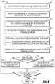
- the accuracy of thresholds used to identify and diagnose faultsis periodically re-evaluated by optimization module 300 ( FIG. 5 ).
- Optimization module 300uses the information in database 30 to adjust the HVAC system operating conditions detection threshold levels for the measured HVAC system parameters and derived (e.g., calculated) parameters.
- optimization module 300seeks to optimize the optimization parameters on a per-diagnosable fault basis.
- step 305datasets for each diagnosable faults are selected for processing.
- the collected datasetsare processed for each specific set of optimization parameter values being analyzed to produce a set of weighted total sums for each diagnosable fault.
- Each set of optimization values within the selected datasetare identified (step 310 ).
- the weighted total sum for each unique set of optimization valuesare determined in step 315 , and in step 320 , a mean and a standard deviation are determined.
- step 325a z-score is computed when processing is completed for each dataset.
- Each z-scoreis computed using the following equation: (the diagnosable fault threshold—the mean weighted total sum)/the standard deviation of the set of weighted total sums.
- the most negative z-scoreis associated with the set of optimization parameter values that statistically represent the lowest probability of the FDD system incorrectly diagnosing faults going forward (e.g., in future diagnosis). This conclusion is based on the observation that each calculated set of weighted total sums approximates a normal distribution. Therefore, the goal of the optimization module is to obtain the most negative z-score possible, per diagnosable fault, by varying, and effectively searching through, combinations of optimization parameter values until the most negative z-score is found by the module (step 330 ).
- the task of searching through combinations of optimization parameter values within the allowed ranges thereofmay be accomplished via the Newton-Raphson numerical analysis method modified for this particular application, e.g. approximating derivatives by using the slope of a line through two adjacent points, adding logic to skip over optimization parameter values that result in no change in the weighted total sum output, etc., or may be performed using any other suitable numerical analysis approximation method.
- optimization module 300is applicable to datasets that contain field service personnel provided feedback of the correct fault diagnosis (including the non-existence of a fault), computer simulations, lab-obtained datasets, and/or any combination thereof.
- one measure of the estimated risk of misdiagnosing any specific faultis equal to the tabled, or calculated, value of the standard normal probability of the z-score that is associated with the optimum set of optimization parameter values implemented for the diagnosable fault under analysis.
- optimization module 400may optionally conclude that if the estimated risk of the FDD system misdiagnosing a fault, as determined by the fault's z-score, is higher than a predetermined threshold, then the operator of the FDD system may be alerted, or additionally or alternatively, the FDD system may be inhibited from diagnosing that specific fault until the estimated risk of misdiagnosis of that fault goes below the predetermined threshold associated with that specific diagnosable fault during a subsequent optimization sequence (steps 435 - 445 ).
- Other relevant statisticssuch as the normality of the distribution of the weighted total sums obtained using the optimum set of optimization parameter values for each diagnosable fault, may optionally be computed for the operator and/or stored in database 30 .
- any of aspects 1-13 belowcan be combined with each other in any combination and combined with any of aspects 14-20.
- Any of aspects 14-20can be combined with each other in any combination.
- An HVAC fault detection methodcomprising receiving, at a processor, signals indicative of sensed HVAC system operating parameters from a data gathering device of an HVAC system; identifying which of the plurality of sensed HVAC system operating parameters exceeds a parameter threshold to determine a set of error parameters; determining, from the set of error parameters, a potential fault and a corresponding fault threshold; multiplying each error parameter by a predetermined weighting factor to generate a weighted error parameter; summing the weighted error parameter to generate a summed value; confirming that the potential fault is a detected fault in response to a determination that the summed value exceeds the fault threshold; storing, in a database, a dataset including a set of optimization parameters comprising the parameter thresholds, the predetermined weighting factors, and the fault threshold.
- Aspect 2The HVAC fault detection method in accordance with aspect 1, wherein the set of optimization parameters further comprises parameters selected from the group consisting of sensed HVAC system operating parameters, the set of error parameters, and the detected fault.
- Aspect 3The HVAC fault detection method in accordance with any of aspects 1-2, further comprising transmitting a fault message indicative of the identified fault.
- Aspect 4The HVAC fault detection method in accordance with any of aspects 1-3, further comprising providing an initial set of parameter thresholds.
- Aspect 5The HVAC fault detection method in accordance with any of aspects 1-4, further comprising performing noise reduction on at least one of the received signals.
- Aspect 6The HVAC fault detection method in accordance with any of aspects 1-5, further comprising normalizing an HVAC system operating parameter to fall within a standardized range.
- Aspect 7The HVAC fault detection method in accordance with any of aspects 1-6, further comprising receiving, at the processor, feedback data indicative of whether the detected fault is an actual fault; and storing, in the dataset, the feedback data.
- Aspect 8The HVAC fault detection method in accordance with any of aspects 1-7, further comprising selecting, from the database, a plurality of datasets having a common detected fault; identifying, within the selected plurality of datasets, each unique set of optimization parameters; obtaining, for each of the selected plurality of datasets, a weighted total sum of the optimization parameters; determining a z-score for each set of weighted total sums of the optimization parameters; identifying the set of optimization parameters having the most negative z-score; and utilizing the set of optimization parameters having the most negative z-score as predetermined weighting factors.
- Aspect 9The HVAC fault detection method in accordance with any of aspects 1-8, further comprising comparing the z-score of the set of optimization parameters having the most negative z-score to a threshold.
- Aspect 10The HVAC fault detection method in accordance with any of aspects 1-9, further comprising transmitting an alert in response to the comparing.
- Aspect 11The HVAC fault detection method in accordance with any of aspects 1-10, further comprising inhibiting detection of the common detected fault in response to the comparing.
- Aspect 12The HVAC fault detection method in accordance with any of aspects 1-11, further comprising determining a mean of each set of weighted total sums of the optimization parameters; and determining a standard deviation of each set of weighted total sums of the optimization parameters.
- An HVAC fault detection systemcomprising a data gathering module configured for receiving HVAC system operating parameters from components of an HVAC system and for transmitting the received HVAC system operating parameters to a recipient device; a data analysis module configured for receiving HVAC system operating parameters from the data gathering module and comprising: a database configured for storing received HVAC system operating parameters; a processor operatively coupled to the database; a memory operatively coupled to the processor and including a set of executable instructions which, when executed by the processor, cause the processor to identify which of the plurality of sensed HVAC system operating parameters exceeds a parameter threshold to determine a set of error parameters; determine, from the set of error parameters, a potential fault and a corresponding fault threshold; multiply each error parameter by a predetermined weighting factor to generate a set of weighted error parameters; sum the set of weighted error parameters to generate a summed value; confirm that the potential fault is a detected fault in response to a determination that the summed value exceeds the fault threshold; and store, in the database, a dataset including a set of
- Aspect 15The HVAC fault detection system in accordance with aspect 14, wherein the memory includes executable instructions that further cause the processor to cause a transmission of a fault message indicative of the identified fault.
- Aspect 16The HVAC fault detection system in accordance with any of aspects 14-15, wherein the memory includes executable instructions that further cause the processor to normalize an HVAC system operating parameter to fall within a standardized range.
- Aspect 17The HVAC fault detection system in accordance with any of aspects 14-16, wherein the memory includes executable instructions that further cause the processor to identify, within the selected plurality of datasets, each unique set of optimization parameters; obtain, for each of the selected plurality of datasets, a weighted total sum of the optimization parameters; determine a z-score for each set of weighted total sums of the optimization parameters; identify the set of optimization parameters having the most negative z-score; and utilize the identified set of optimization parameters having the most negative z-score as predetermined weighting factors.
- Aspect 18The HVAC fault detection system in accordance with any of aspects 14-17, wherein the memory includes executable instructions that further cause the processor to compare the z-score of the set of optimization parameters having the most negative z-score to a threshold.
- Aspect 19The HVAC fault detection system in accordance with any of aspects 14-18, wherein the memory includes executable instructions that further cause the processor to transmit an alert in response to the comparing.
Landscapes
- Engineering & Computer Science (AREA)
- General Engineering & Computer Science (AREA)
- Mechanical Engineering (AREA)
- Combustion & Propulsion (AREA)
- Chemical & Material Sciences (AREA)
- Physics & Mathematics (AREA)
- General Physics & Mathematics (AREA)
- Theoretical Computer Science (AREA)
- Signal Processing (AREA)
- Mathematical Physics (AREA)
- Artificial Intelligence (AREA)
- Software Systems (AREA)
- Automation & Control Theory (AREA)
- Fuzzy Systems (AREA)
- Human Computer Interaction (AREA)
- Health & Medical Sciences (AREA)
- Medical Informatics (AREA)
- Evolutionary Computation (AREA)
- Computer Vision & Pattern Recognition (AREA)
- Biomedical Technology (AREA)
- Quality & Reliability (AREA)
- Computing Systems (AREA)
- Data Mining & Analysis (AREA)
- Air Conditioning Control Device (AREA)
- Testing And Monitoring For Control Systems (AREA)
Abstract
Description
Claims (18)
Priority Applications (1)
| Application Number | Priority Date | Filing Date | Title |
|---|---|---|---|
| US15/186,756US10592821B2 (en) | 2015-06-19 | 2016-06-20 | Self-learning fault detection for HVAC systems |
Applications Claiming Priority (3)
| Application Number | Priority Date | Filing Date | Title |
|---|---|---|---|
| US201562182106P | 2015-06-19 | 2015-06-19 | |
| US201562182119P | 2015-06-19 | 2015-06-19 | |
| US15/186,756US10592821B2 (en) | 2015-06-19 | 2016-06-20 | Self-learning fault detection for HVAC systems |
Publications (2)
| Publication Number | Publication Date |
|---|---|
| US20160370799A1 US20160370799A1 (en) | 2016-12-22 |
| US10592821B2true US10592821B2 (en) | 2020-03-17 |
Family
ID=57587026
Family Applications (2)
| Application Number | Title | Priority Date | Filing Date |
|---|---|---|---|
| US15/186,715AbandonedUS20160370023A1 (en) | 2015-06-19 | 2016-06-20 | Fault detection and diagnostics system utilizing service personnel feedback for improved accuracy |
| US15/186,756Active2037-11-21US10592821B2 (en) | 2015-06-19 | 2016-06-20 | Self-learning fault detection for HVAC systems |
Family Applications Before (1)
| Application Number | Title | Priority Date | Filing Date |
|---|---|---|---|
| US15/186,715AbandonedUS20160370023A1 (en) | 2015-06-19 | 2016-06-20 | Fault detection and diagnostics system utilizing service personnel feedback for improved accuracy |
Country Status (1)
| Country | Link |
|---|---|
| US (2) | US20160370023A1 (en) |
Cited By (5)
| Publication number | Priority date | Publication date | Assignee | Title |
|---|---|---|---|---|
| US11454409B2 (en)* | 2019-03-15 | 2022-09-27 | Carrier Corporation | Failure detection method for air conditioning system |
| US11460203B2 (en)* | 2017-11-06 | 2022-10-04 | Measured Air Performance, LLC | Exhaust demand control system and methods |
| US20240086274A1 (en)* | 2022-09-14 | 2024-03-14 | Getac Technology Corporation | Server-side remediation for incoming sensor data |
| US12007831B2 (en) | 2021-08-18 | 2024-06-11 | Capital One Services, Llc | Devices and components for machine learning-based signal error correction and methods of use thereof |
| US20240200818A1 (en)* | 2022-12-14 | 2024-06-20 | Trane International Inc. | System and method for controlling the conditioning mode of a climate control device |
Families Citing this family (40)
| Publication number | Priority date | Publication date | Assignee | Title |
|---|---|---|---|---|
| US8992074B2 (en)* | 2012-02-17 | 2015-03-31 | Cypress Envirosystems, Inc. | System and method for conducting heating, ventilation, and air conditioning analytics |
| JP6295113B2 (en)* | 2014-03-17 | 2018-03-14 | ルネサスエレクトロニクス株式会社 | Self-diagnosis device and self-diagnosis method |
| US10288019B2 (en)* | 2016-07-21 | 2019-05-14 | Ford Global Technologies, Llc | Secondary system and method for controlling an engine |
| US20180032969A1 (en) | 2016-07-27 | 2018-02-01 | Johnson Controls Technology Company | Systems and methods for automated diagnostics of hvac systems |
| EP4528174A3 (en)* | 2017-04-06 | 2025-06-11 | Carrier Corporation | Moderate-to-low global warming potential value refrigerant leak detection |
| CN107975907A (en)* | 2017-07-14 | 2018-05-01 | 深圳达实智能股份有限公司 | Hospital's pre-cooled air-conditioning box autodiagnosis method, apparatus, computer installation and storage medium |
| CN107621059A (en)* | 2017-07-14 | 2018-01-23 | 深圳达实智能股份有限公司 | Hospital's combined type wind cabinet automatic fault diagnosis devices, systems, and methods |
| CN107355949A (en)* | 2017-07-21 | 2017-11-17 | 广东乐源数字技术有限公司 | A kind of air-conditioning trouble shooting learning method |
| CN107576011B (en)* | 2017-09-04 | 2019-09-06 | 珠海格力电器股份有限公司 | air conditioner emergency control method and device |
| CN107726535A (en)* | 2017-09-14 | 2018-02-23 | 深圳达实智能股份有限公司 | A kind of hospital's cold emission air-conditioning system fault self-detection method and system |
| CN107676923A (en)* | 2017-09-14 | 2018-02-09 | 深圳达实智能股份有限公司 | A kind of Air conditioning System for Hospitals cooling tower failure automatic judging method and device |
| CN107490156B (en)* | 2017-09-27 | 2019-09-20 | 广东美的暖通设备有限公司 | Three control air-conditionings and its method for diagnosing faults |
| AU2018348784B2 (en) | 2017-10-11 | 2024-01-25 | Airconnect Holdings Pty Ltd | Systems and a method for maintenance of HVAC systems |
| WO2019084784A1 (en)* | 2017-10-31 | 2019-05-09 | 深圳市智美达科技股份有限公司 | Intelligent temperature control method and apparatus, storage medium, central temperature controller and server |
| EP3704421A4 (en)* | 2017-11-01 | 2021-07-28 | Honeywell International Inc. | Determining a cause of a fault in an hvac system |
| US10989427B2 (en)* | 2017-12-20 | 2021-04-27 | Trane International Inc. | HVAC system including smart diagnostic capabilites |
| KR102587127B1 (en) | 2017-12-26 | 2023-10-11 | 삼성전자주식회사 | Method and apparatus for managing operational data of appliance device for failure prediction |
| US10684035B2 (en)* | 2018-01-08 | 2020-06-16 | Trane International Inc. | HVAC system that collects customer feedback in connection with failure triage |
| JP6733704B2 (en)* | 2018-05-31 | 2020-08-05 | ダイキン工業株式会社 | Air conditioning management system and communication control device |
| CN108958224B (en)* | 2018-07-27 | 2021-08-10 | 深圳市元征科技股份有限公司 | Vehicle diagnosis method, diagnosis terminal and diagnosis box |
| CN109708249B (en)* | 2018-12-29 | 2020-06-09 | 珠海格力电器股份有限公司 | Air conditioner component fault prediction method and device and computer equipment |
| CN111486557B (en)* | 2019-01-29 | 2024-02-23 | Urecsys-城市生态系统-室内空气质量管理有限公司 | Libraries, systems, and methods for minimizing air pollution in enclosed structures |
| US11346748B2 (en)* | 2019-05-24 | 2022-05-31 | Hitachi, Ltd | Method for extracting signal in presence of strong noise |
| US11248819B2 (en) | 2019-06-05 | 2022-02-15 | Honeywell International Inc. | Process for adaptable health, degradation and anomaly detection of systems using benchmarks |
| CN110388733B (en) | 2019-07-29 | 2021-11-30 | 广东美的暖通设备有限公司 | Fault risk analysis system and method, air conditioner and computer readable storage medium |
| CN110471380A (en)* | 2019-08-15 | 2019-11-19 | 四川长虹电器股份有限公司 | A kind of air conditioning failure monitoring and method for early warning for smart home system |
| WO2021124457A1 (en)* | 2019-12-17 | 2021-06-24 | 三菱電機株式会社 | Abnormality sign estimation device for air conditioner, abnormality sign estimation model learning device for air conditioner, and air conditioner |
| CN115516254A (en)* | 2020-03-12 | 2022-12-23 | 江森自控泰科知识产权控股有限责任合伙公司 | Systems and methods for controlling variable refrigerant flow systems and devices using artificial intelligence models |
| US11625016B2 (en)* | 2020-08-21 | 2023-04-11 | Siemens Industry, Inc. | Systems and methods for HVAC equipment predictive maintenance using machine learning |
| DE102021105837A1 (en)* | 2021-03-10 | 2022-09-15 | Viessmann Climate Solutions Se | METHOD, MONITORING SYSTEM AND COMPUTER PROGRAM PRODUCT FOR MONITORING A HEATING SYSTEM AND/OR AN AIR CONDITIONING SYSTEM |
| CN113007868B (en)* | 2021-03-30 | 2022-10-21 | 新奥数能科技有限公司 | Control method and device of central air conditioning system and electronic equipment |
| CN113357743B (en)* | 2021-06-21 | 2022-08-26 | 广东美的暖通设备有限公司 | Environment temperature detection method and device, computing equipment and storage medium |
| EP4198656A1 (en)* | 2021-12-15 | 2023-06-21 | Viessmann Climate Solutions SE | Method and system for monitoring an hvac apparatus |
| US20230280061A1 (en)* | 2022-03-01 | 2023-09-07 | Johnson Controls Tyco IP Holdings LLP | Building automation system with edge processing diversity |
| CN115143590B (en)* | 2022-06-30 | 2024-04-30 | 北京小米移动软件有限公司 | Control parameter processing method, device and storage medium |
| CN115264756B (en)* | 2022-07-13 | 2023-08-01 | 青岛海信日立空调系统有限公司 | Emergency treatment method and device for air conditioning system |
| DE102022121116A1 (en)* | 2022-08-22 | 2024-02-22 | ebm-papst neo GmbH & Co. KG | System and method for monitoring a system with a controllable system component |
| US20240117982A1 (en)* | 2022-10-10 | 2024-04-11 | Haier Us Appliance Solutions, Inc. | Fault diagnosis method for an air conditioner appliance |
| CN116860831A (en)* | 2023-06-30 | 2023-10-10 | 西安航天动力试验技术研究所 | Fault diagnosis auxiliary decision-making method for real-time data |
| CN118365315B (en)* | 2024-06-19 | 2024-11-19 | 新能众维电力发展有限公司 | Power distribution room fault operation and maintenance management method based on multi-source data analysis |
Citations (75)
| Publication number | Priority date | Publication date | Assignee | Title |
|---|---|---|---|---|
| US5289176A (en) | 1992-03-19 | 1994-02-22 | Aeg Transportation Systems, Inc. | Multi-master resolution of a serial bus |
| US5512890A (en) | 1992-02-19 | 1996-04-30 | Namco Controls Corporation | Sensor connection system |
| US5862322A (en) | 1994-03-14 | 1999-01-19 | Dun & Bradstreet Software Services, Inc. | Method and apparatus for facilitating customer service communications in a computing environment |
| US5983364A (en) | 1997-05-12 | 1999-11-09 | System Soft Corporation | System and method for diagnosing computer faults |
| US6065136A (en) | 1997-02-18 | 2000-05-16 | Shimadzu Corporation | System for remote diagnosis of device troubles |
| US6223544B1 (en) | 1999-08-05 | 2001-05-01 | Johnson Controls Technology Co. | Integrated control and fault detection of HVAC equipment |
| US6266721B1 (en) | 1997-05-13 | 2001-07-24 | Micron Electronics, Inc. | System architecture for remote access and control of environmental management |
| US6279125B1 (en) | 1998-06-24 | 2001-08-21 | Micron Technology, Inc. | Computer system diagnostics |
| US6343236B1 (en) | 1999-04-02 | 2002-01-29 | General Electric Company | Method and system for analyzing fault log data for diagnostics |
| US6393490B1 (en) | 1997-12-18 | 2002-05-21 | Ian James Stiles | Method and system for a programmatic feedback process for end-user support |
| US6446058B1 (en) | 1999-04-26 | 2002-09-03 | At&T Corp. | Computer platform alarm and control system |
| US6496575B1 (en) | 1998-06-08 | 2002-12-17 | Gatespace Ab | Application and communication platform for connectivity based services |
| US20020194550A1 (en) | 2001-06-15 | 2002-12-19 | Lopke Michael S. | Enduser diagnostic system and method for computer-based error interpretation |
| US20030056140A1 (en) | 2000-05-05 | 2003-03-20 | Taylor David K. | Help desk systems and methods for use with communications networks |
| US6681348B1 (en) | 2000-12-15 | 2004-01-20 | Microsoft Corporation | Creation of mini dump files from full dump files |
| US6679072B2 (en) | 1995-06-07 | 2004-01-20 | Copeland Corporation | Diagnostic system and method for a cooling system |
| US20040203379A1 (en) | 2002-04-23 | 2004-10-14 | Johnson Controls Technology Company | Bluetooth transmission of vehicle diagnostic information |
| US20040218591A1 (en) | 2003-04-29 | 2004-11-04 | Craig Ogawa | Bridge apparatus and methods of operation |
| US20040249914A1 (en) | 2003-05-21 | 2004-12-09 | Flocken Philip A. | Computer service using automated local diagnostic data collection and automated remote analysis |
| US6851621B1 (en) | 2003-08-18 | 2005-02-08 | Honeywell International Inc. | PDA diagnosis of thermostats |
| US6892317B1 (en) | 1999-12-16 | 2005-05-10 | Xerox Corporation | Systems and methods for failure prediction, diagnosis and remediation using data acquisition and feedback for a distributed electronic system |
| US20050171736A1 (en) | 2004-02-02 | 2005-08-04 | United Technologies Corporation | Health monitoring and diagnostic/prognostic system for an ORC plant |
| US20050275525A1 (en) | 2004-03-25 | 2005-12-15 | Siemens Building Technologies, Inc. | Method and apparatus for graphical display of a condition in a building system with a mobile display unit |
| US7000422B2 (en) | 2000-03-14 | 2006-02-21 | Hussmann Corporation | Refrigeration system and method of configuring the same |
| US7053767B2 (en) | 1998-06-22 | 2006-05-30 | Statsignal Systems, Inc. | System and method for monitoring and controlling remote devices |
| US7058542B2 (en) | 2000-07-07 | 2006-06-06 | Metso Automation Oy | Wireless diagnostic system in industrial processes |
| US7083109B2 (en) | 2003-08-18 | 2006-08-01 | Honeywell International Inc. | Thermostat having modulated and non-modulated provisions |
| US7120819B1 (en) | 2001-11-15 | 2006-10-10 | 3Com Corporation | Method and system for fault diagnosis in a data network |
| US7188482B2 (en) | 2004-08-27 | 2007-03-13 | Carrier Corporation | Fault diagnostics and prognostics based on distance fault classifiers |
| US7191364B2 (en) | 2003-11-14 | 2007-03-13 | Microsoft Corporation | Automatic root cause analysis and diagnostics engine |
| US7302313B2 (en) | 2001-02-07 | 2007-11-27 | Aircuity, Inc. | Air quality monitoring systems and methods |
| US20080129307A1 (en) | 2006-11-30 | 2008-06-05 | Honeywell International Inc. | Differential arc fault detection |
| US7421850B2 (en) | 2000-03-14 | 2008-09-09 | Hussman Corporation | Refrigeration system and method of operating the same |
| US20080217471A1 (en) | 2007-03-05 | 2008-09-11 | Honeywell International Inc. | Intelligent aircraft secondary power distribution system that facilitates condition based maintenance |
| US20080262860A1 (en) | 2007-04-20 | 2008-10-23 | Sap Ag | System and Method for Supporting Software |
| US7627455B2 (en) | 2004-08-31 | 2009-12-01 | Watlow Electric Manufacturing Company | Distributed diagnostic operations system |
| US20100106318A1 (en) | 2008-10-27 | 2010-04-29 | Lennox Industries Inc. | Alarm and diagnostics system and method for a distributed- architecture heating, ventilation and air conditioning network |
| US20100102973A1 (en) | 2008-10-27 | 2010-04-29 | Lennox Industries, Inc. | Alarm and diagnostics system and method for a distributed-architecture heating, ventilation and air conditioning network |
| US20100106311A1 (en) | 2008-10-27 | 2010-04-29 | Lennox Industries Inc. | Alarm and diagnostics system and method for a distributed architecture heating, ventilation and conditioning network |
| US20100106310A1 (en) | 2008-10-27 | 2010-04-29 | Lennox Industries Inc. | Alarm and diagnostics system and method for a distributed- architecture heating, ventilation and air conditioning network |
| US20100106809A1 (en) | 2008-10-27 | 2010-04-29 | Lennox Industries Inc. | Alarm and diagnostics system and method for a distributed-architecture heating, ventilation and air conditioning network |
| US20100106316A1 (en) | 2008-10-27 | 2010-04-29 | Lennox Industries Inc. | Alarm and diagnostics system and method for a distributed architecture heating, ventilation and air conditioning network |
| US20100106312A1 (en) | 2008-10-27 | 2010-04-29 | Lennox Industries Inc. | Alarm and diagnostics system and method for a distributed-architecture heating, ventilation and air conditioning network |
| US20100102948A1 (en) | 2008-10-27 | 2010-04-29 | Lennox Industries Inc. | Alarm and diagnostics system and method for a distributed architecture heating, ventilation and air conditioning network |
| US20100102136A1 (en) | 2008-10-27 | 2010-04-29 | Lennox Industries Inc. | Alarm and diagnostics system and method for a distributed architecture heating, ventilation and air conditioning network |
| US7890318B2 (en) | 2007-05-23 | 2011-02-15 | Xerox Corporation | Informing troubleshooting sessions with device data |
| US20120215398A1 (en) | 2007-06-28 | 2012-08-23 | Innova Electronics Corporation | Diagnostic Process for Home Electronic Devics |
| US8332819B2 (en) | 2007-05-03 | 2012-12-11 | Siemens Industry, Inc. | Diagnostic and trouble-shooting methods in a wireless control and sensor network |
| US8370020B2 (en) | 2007-06-22 | 2013-02-05 | Lear Corporation | Method and system for communicating vehicle diagnostic data to internet server via Bluetooth enabled cell phone for subsequent retrieval |
| US8532808B2 (en) | 2009-06-22 | 2013-09-10 | Johnson Controls Technology Company | Systems and methods for measuring and verifying energy savings in buildings |
| US20130304278A1 (en) | 2012-05-09 | 2013-11-14 | Ieon C. Chen | Smart Phone App-Based Remote Vehicle Diagnostic System and Method |
| US8600556B2 (en) | 2009-06-22 | 2013-12-03 | Johnson Controls Technology Company | Smart building manager |
| US8606374B2 (en) | 2010-09-14 | 2013-12-10 | Nest Labs, Inc. | Thermodynamic modeling for enclosures |
| US20140074730A1 (en) | 2012-02-28 | 2014-03-13 | Emerson Climate Technologies, Inc. | Hvac system remote monitoring and diagnosis |
| US8682509B2 (en) | 2007-02-16 | 2014-03-25 | Honeywell International Inc. | Vehicle monitoring system |
| US20140142904A1 (en) | 2012-11-16 | 2014-05-22 | Johnson Controls Technology Company | Systems and methods for generating an energy use model for a building |
| US20140142727A1 (en) | 2011-03-02 | 2014-05-22 | Carrier Corporation | SPC Fault Detection and Diagnostics Algorithm |
| US8781633B2 (en) | 2009-04-15 | 2014-07-15 | Roberto Fata | Monitoring and control systems and methods |
| US20140207394A1 (en) | 2013-01-23 | 2014-07-24 | JB Industries, Inc. | Systems and methods for communicating with heating, ventilation and air conditioning equipment |
| US20140249680A1 (en) | 2011-09-30 | 2014-09-04 | Johnson Controls Technology Company | Systems and methods for controlling energy use in a building management system using energy budgets |
| US20140266755A1 (en) | 2013-03-15 | 2014-09-18 | Emerson Electric Co. | Hvac system remote monitoring and diagnosis |
| US20140262134A1 (en) | 2013-03-15 | 2014-09-18 | Emerson Electric Co. | Hvac system remote monitoring and diagnosis |
| US8843238B2 (en) | 2011-09-30 | 2014-09-23 | Johnson Controls Technology Company | Systems and methods for controlling energy use in a building management system using energy budgets |
| US20140297208A1 (en) | 2011-02-28 | 2014-10-02 | Emerson Electric Co. | Remote HVAC Monitoring And Diagnosis |
| US8924266B2 (en) | 2009-04-30 | 2014-12-30 | Bank Of America Corporation | Self-service device inventory information control |
| US8935110B2 (en) | 2008-10-24 | 2015-01-13 | The Technology Partnership Plc | Apparatus for analysing an interior energy system |
| US9021462B2 (en) | 2013-03-13 | 2015-04-28 | Johnson Controls Technology Company | Systems and methods for provisioning equipment |
| US9135667B2 (en) | 2012-11-16 | 2015-09-15 | Johnson Controls Technology Company | Systems and methods for building energy use benchmarking |
| US20150323211A1 (en) | 2014-05-07 | 2015-11-12 | Emerson Electric Co. | Hvac system grading systems and methods |
| US9196009B2 (en) | 2009-06-22 | 2015-11-24 | Johnson Controls Technology Company | Systems and methods for detecting changes in energy usage in a building |
| US20150378373A1 (en)* | 2014-06-25 | 2015-12-31 | University Of Arizona | Data-driven hvac optimization |
| US9286582B2 (en) | 2009-06-22 | 2016-03-15 | Johnson Controls Technology Company | Systems and methods for detecting changes in energy usage in a building |
| US20160110238A1 (en) | 2014-10-16 | 2016-04-21 | International Business Machines Corporation | Automated diagnosis of software crashes |
| US20160203036A1 (en)* | 2015-01-09 | 2016-07-14 | Ecorithm, Inc. | Machine learning-based fault detection system |
| US20160313011A1 (en)* | 2015-04-23 | 2016-10-27 | Melink Corporation | Optimal energy saving for kitchen hood systems |
Family Cites Families (3)
| Publication number | Priority date | Publication date | Assignee | Title |
|---|---|---|---|---|
| US20120072029A1 (en)* | 2010-09-20 | 2012-03-22 | Heatvu Inc. | Intelligent system and method for detecting and diagnosing faults in heating, ventilating and air conditioning (hvac) equipment |
| US9471722B2 (en)* | 2013-02-05 | 2016-10-18 | Johnson Controls Technology Company | Systems and methods for evaluating a fault condition in a building |
| EP3268821B1 (en)* | 2015-03-11 | 2020-07-15 | Siemens Industry, Inc. | Cascaded identification in building automation |
- 2016
- 2016-06-20USUS15/186,715patent/US20160370023A1/ennot_activeAbandoned
- 2016-06-20USUS15/186,756patent/US10592821B2/enactiveActive
Patent Citations (88)
| Publication number | Priority date | Publication date | Assignee | Title |
|---|---|---|---|---|
| US5512890A (en) | 1992-02-19 | 1996-04-30 | Namco Controls Corporation | Sensor connection system |
| US5289176A (en) | 1992-03-19 | 1994-02-22 | Aeg Transportation Systems, Inc. | Multi-master resolution of a serial bus |
| US5862322A (en) | 1994-03-14 | 1999-01-19 | Dun & Bradstreet Software Services, Inc. | Method and apparatus for facilitating customer service communications in a computing environment |
| US6679072B2 (en) | 1995-06-07 | 2004-01-20 | Copeland Corporation | Diagnostic system and method for a cooling system |
| US6065136A (en) | 1997-02-18 | 2000-05-16 | Shimadzu Corporation | System for remote diagnosis of device troubles |
| US5983364A (en) | 1997-05-12 | 1999-11-09 | System Soft Corporation | System and method for diagnosing computer faults |
| US6266721B1 (en) | 1997-05-13 | 2001-07-24 | Micron Electronics, Inc. | System architecture for remote access and control of environmental management |
| US6393490B1 (en) | 1997-12-18 | 2002-05-21 | Ian James Stiles | Method and system for a programmatic feedback process for end-user support |
| US6496575B1 (en) | 1998-06-08 | 2002-12-17 | Gatespace Ab | Application and communication platform for connectivity based services |
| US7053767B2 (en) | 1998-06-22 | 2006-05-30 | Statsignal Systems, Inc. | System and method for monitoring and controlling remote devices |
| US6279125B1 (en) | 1998-06-24 | 2001-08-21 | Micron Technology, Inc. | Computer system diagnostics |
| US6343236B1 (en) | 1999-04-02 | 2002-01-29 | General Electric Company | Method and system for analyzing fault log data for diagnostics |
| US6446058B1 (en) | 1999-04-26 | 2002-09-03 | At&T Corp. | Computer platform alarm and control system |
| US6223544B1 (en) | 1999-08-05 | 2001-05-01 | Johnson Controls Technology Co. | Integrated control and fault detection of HVAC equipment |
| US6892317B1 (en) | 1999-12-16 | 2005-05-10 | Xerox Corporation | Systems and methods for failure prediction, diagnosis and remediation using data acquisition and feedback for a distributed electronic system |
| US7421850B2 (en) | 2000-03-14 | 2008-09-09 | Hussman Corporation | Refrigeration system and method of operating the same |
| US7000422B2 (en) | 2000-03-14 | 2006-02-21 | Hussmann Corporation | Refrigeration system and method of configuring the same |
| US20030056140A1 (en) | 2000-05-05 | 2003-03-20 | Taylor David K. | Help desk systems and methods for use with communications networks |
| US7058542B2 (en) | 2000-07-07 | 2006-06-06 | Metso Automation Oy | Wireless diagnostic system in industrial processes |
| US6681348B1 (en) | 2000-12-15 | 2004-01-20 | Microsoft Corporation | Creation of mini dump files from full dump files |
| US7302313B2 (en) | 2001-02-07 | 2007-11-27 | Aircuity, Inc. | Air quality monitoring systems and methods |
| US20020194550A1 (en) | 2001-06-15 | 2002-12-19 | Lopke Michael S. | Enduser diagnostic system and method for computer-based error interpretation |
| US7120819B1 (en) | 2001-11-15 | 2006-10-10 | 3Com Corporation | Method and system for fault diagnosis in a data network |
| US20040203379A1 (en) | 2002-04-23 | 2004-10-14 | Johnson Controls Technology Company | Bluetooth transmission of vehicle diagnostic information |
| US20040218591A1 (en) | 2003-04-29 | 2004-11-04 | Craig Ogawa | Bridge apparatus and methods of operation |
| US20040249914A1 (en) | 2003-05-21 | 2004-12-09 | Flocken Philip A. | Computer service using automated local diagnostic data collection and automated remote analysis |
| US6851621B1 (en) | 2003-08-18 | 2005-02-08 | Honeywell International Inc. | PDA diagnosis of thermostats |
| US7083109B2 (en) | 2003-08-18 | 2006-08-01 | Honeywell International Inc. | Thermostat having modulated and non-modulated provisions |
| US7191364B2 (en) | 2003-11-14 | 2007-03-13 | Microsoft Corporation | Automatic root cause analysis and diagnostics engine |
| US20050171736A1 (en) | 2004-02-02 | 2005-08-04 | United Technologies Corporation | Health monitoring and diagnostic/prognostic system for an ORC plant |
| US20050275525A1 (en) | 2004-03-25 | 2005-12-15 | Siemens Building Technologies, Inc. | Method and apparatus for graphical display of a condition in a building system with a mobile display unit |
| US7188482B2 (en) | 2004-08-27 | 2007-03-13 | Carrier Corporation | Fault diagnostics and prognostics based on distance fault classifiers |
| US7627455B2 (en) | 2004-08-31 | 2009-12-01 | Watlow Electric Manufacturing Company | Distributed diagnostic operations system |
| US20080129307A1 (en) | 2006-11-30 | 2008-06-05 | Honeywell International Inc. | Differential arc fault detection |
| US7489138B2 (en) | 2006-11-30 | 2009-02-10 | Honeywell International Inc. | Differential arc fault detection |
| US8682509B2 (en) | 2007-02-16 | 2014-03-25 | Honeywell International Inc. | Vehicle monitoring system |
| US7634329B2 (en) | 2007-03-05 | 2009-12-15 | Honeywell International Inc. | Intelligent aircraft secondary power distribution system that facilitates condition based maintenance |
| US20080217471A1 (en) | 2007-03-05 | 2008-09-11 | Honeywell International Inc. | Intelligent aircraft secondary power distribution system that facilitates condition based maintenance |
| US20080262860A1 (en) | 2007-04-20 | 2008-10-23 | Sap Ag | System and Method for Supporting Software |
| US8332819B2 (en) | 2007-05-03 | 2012-12-11 | Siemens Industry, Inc. | Diagnostic and trouble-shooting methods in a wireless control and sensor network |
| US7890318B2 (en) | 2007-05-23 | 2011-02-15 | Xerox Corporation | Informing troubleshooting sessions with device data |
| US8370020B2 (en) | 2007-06-22 | 2013-02-05 | Lear Corporation | Method and system for communicating vehicle diagnostic data to internet server via Bluetooth enabled cell phone for subsequent retrieval |
| US9026400B2 (en) | 2007-06-28 | 2015-05-05 | Innova Electonics, Inc. | Diagnostic process for home electronic devices |
| US20120215398A1 (en) | 2007-06-28 | 2012-08-23 | Innova Electronics Corporation | Diagnostic Process for Home Electronic Devics |
| US8935110B2 (en) | 2008-10-24 | 2015-01-13 | The Technology Partnership Plc | Apparatus for analysing an interior energy system |
| US20100106312A1 (en) | 2008-10-27 | 2010-04-29 | Lennox Industries Inc. | Alarm and diagnostics system and method for a distributed-architecture heating, ventilation and air conditioning network |
| US20100106311A1 (en) | 2008-10-27 | 2010-04-29 | Lennox Industries Inc. | Alarm and diagnostics system and method for a distributed architecture heating, ventilation and conditioning network |
| US20100102948A1 (en) | 2008-10-27 | 2010-04-29 | Lennox Industries Inc. | Alarm and diagnostics system and method for a distributed architecture heating, ventilation and air conditioning network |
| US20100106316A1 (en) | 2008-10-27 | 2010-04-29 | Lennox Industries Inc. | Alarm and diagnostics system and method for a distributed architecture heating, ventilation and air conditioning network |
| US20100106809A1 (en) | 2008-10-27 | 2010-04-29 | Lennox Industries Inc. | Alarm and diagnostics system and method for a distributed-architecture heating, ventilation and air conditioning network |
| US20100106310A1 (en) | 2008-10-27 | 2010-04-29 | Lennox Industries Inc. | Alarm and diagnostics system and method for a distributed- architecture heating, ventilation and air conditioning network |
| US8433446B2 (en) | 2008-10-27 | 2013-04-30 | Lennox Industries, Inc. | Alarm and diagnostics system and method for a distributed-architecture heating, ventilation and air conditioning network |
| US8437878B2 (en) | 2008-10-27 | 2013-05-07 | Lennox Industries Inc. | Alarm and diagnostics system and method for a distributed architecture heating, ventilation and air conditioning network |
| US8463442B2 (en) | 2008-10-27 | 2013-06-11 | Lennox Industries, Inc. | Alarm and diagnostics system and method for a distributed architecture heating, ventilation and air conditioning network |
| US20100106318A1 (en) | 2008-10-27 | 2010-04-29 | Lennox Industries Inc. | Alarm and diagnostics system and method for a distributed- architecture heating, ventilation and air conditioning network |
| US8548630B2 (en) | 2008-10-27 | 2013-10-01 | Lennox Industries, Inc. | Alarm and diagnostics system and method for a distributed-architecture heating, ventilation and air conditioning network |
| US20100102136A1 (en) | 2008-10-27 | 2010-04-29 | Lennox Industries Inc. | Alarm and diagnostics system and method for a distributed architecture heating, ventilation and air conditioning network |
| US8725298B2 (en) | 2008-10-27 | 2014-05-13 | Lennox Industries, Inc. | Alarm and diagnostics system and method for a distributed architecture heating, ventilation and conditioning network |
| US20140354440A1 (en) | 2008-10-27 | 2014-12-04 | Lennox Industries Inc. | Alarm and diagnostics system and method for a distributed-architecture heating, ventilation and air conditioning network |
| US8655491B2 (en) | 2008-10-27 | 2014-02-18 | Lennox Industries Inc. | Alarm and diagnostics system and method for a distributed architecture heating, ventilation and air conditioning network |
| US20100102973A1 (en) | 2008-10-27 | 2010-04-29 | Lennox Industries, Inc. | Alarm and diagnostics system and method for a distributed-architecture heating, ventilation and air conditioning network |
| US8781633B2 (en) | 2009-04-15 | 2014-07-15 | Roberto Fata | Monitoring and control systems and methods |
| US8924266B2 (en) | 2009-04-30 | 2014-12-30 | Bank Of America Corporation | Self-service device inventory information control |
| US8600556B2 (en) | 2009-06-22 | 2013-12-03 | Johnson Controls Technology Company | Smart building manager |
| US9196009B2 (en) | 2009-06-22 | 2015-11-24 | Johnson Controls Technology Company | Systems and methods for detecting changes in energy usage in a building |
| US9286582B2 (en) | 2009-06-22 | 2016-03-15 | Johnson Controls Technology Company | Systems and methods for detecting changes in energy usage in a building |
| US8532808B2 (en) | 2009-06-22 | 2013-09-10 | Johnson Controls Technology Company | Systems and methods for measuring and verifying energy savings in buildings |
| US20140222217A1 (en) | 2010-09-14 | 2014-08-07 | Nest Labs, Inc. | Thermodynamic modeling for enclosures |
| US8606374B2 (en) | 2010-09-14 | 2013-12-10 | Nest Labs, Inc. | Thermodynamic modeling for enclosures |
| US20140297208A1 (en) | 2011-02-28 | 2014-10-02 | Emerson Electric Co. | Remote HVAC Monitoring And Diagnosis |
| US20140142727A1 (en) | 2011-03-02 | 2014-05-22 | Carrier Corporation | SPC Fault Detection and Diagnostics Algorithm |
| US20140249680A1 (en) | 2011-09-30 | 2014-09-04 | Johnson Controls Technology Company | Systems and methods for controlling energy use in a building management system using energy budgets |
| US8843238B2 (en) | 2011-09-30 | 2014-09-23 | Johnson Controls Technology Company | Systems and methods for controlling energy use in a building management system using energy budgets |
| US20140074730A1 (en) | 2012-02-28 | 2014-03-13 | Emerson Climate Technologies, Inc. | Hvac system remote monitoring and diagnosis |
| US9002554B2 (en) | 2012-05-09 | 2015-04-07 | Innova Electronics, Inc. | Smart phone app-based remote vehicle diagnostic system and method |
| US20130304278A1 (en) | 2012-05-09 | 2013-11-14 | Ieon C. Chen | Smart Phone App-Based Remote Vehicle Diagnostic System and Method |
| US9135667B2 (en) | 2012-11-16 | 2015-09-15 | Johnson Controls Technology Company | Systems and methods for building energy use benchmarking |
| US20140142904A1 (en) | 2012-11-16 | 2014-05-22 | Johnson Controls Technology Company | Systems and methods for generating an energy use model for a building |
| US9152610B2 (en) | 2012-11-16 | 2015-10-06 | Johnson Controls Technology Company | Systems and methods for generating an energy use model for a building |
| US20140207394A1 (en) | 2013-01-23 | 2014-07-24 | JB Industries, Inc. | Systems and methods for communicating with heating, ventilation and air conditioning equipment |
| US9021462B2 (en) | 2013-03-13 | 2015-04-28 | Johnson Controls Technology Company | Systems and methods for provisioning equipment |
| US20140262134A1 (en) | 2013-03-15 | 2014-09-18 | Emerson Electric Co. | Hvac system remote monitoring and diagnosis |
| US20140266755A1 (en) | 2013-03-15 | 2014-09-18 | Emerson Electric Co. | Hvac system remote monitoring and diagnosis |
| US20150323211A1 (en) | 2014-05-07 | 2015-11-12 | Emerson Electric Co. | Hvac system grading systems and methods |
| US20150378373A1 (en)* | 2014-06-25 | 2015-12-31 | University Of Arizona | Data-driven hvac optimization |
| US20160110238A1 (en) | 2014-10-16 | 2016-04-21 | International Business Machines Corporation | Automated diagnosis of software crashes |
| US20160203036A1 (en)* | 2015-01-09 | 2016-07-14 | Ecorithm, Inc. | Machine learning-based fault detection system |
| US20160313011A1 (en)* | 2015-04-23 | 2016-10-27 | Melink Corporation | Optimal energy saving for kitchen hood systems |
Cited By (8)
| Publication number | Priority date | Publication date | Assignee | Title |
|---|---|---|---|---|
| US11460203B2 (en)* | 2017-11-06 | 2022-10-04 | Measured Air Performance, LLC | Exhaust demand control system and methods |
| US11698202B2 (en) | 2017-11-06 | 2023-07-11 | Measured Air Performance, LLC | Exhaust demand control system and methods |
| US11933508B2 (en) | 2017-11-06 | 2024-03-19 | Measured Air Performance, LLC | Exhaust demand control system and methods |
| US11454409B2 (en)* | 2019-03-15 | 2022-09-27 | Carrier Corporation | Failure detection method for air conditioning system |
| US12007831B2 (en) | 2021-08-18 | 2024-06-11 | Capital One Services, Llc | Devices and components for machine learning-based signal error correction and methods of use thereof |
| US20240086274A1 (en)* | 2022-09-14 | 2024-03-14 | Getac Technology Corporation | Server-side remediation for incoming sensor data |
| US12093125B2 (en)* | 2022-09-14 | 2024-09-17 | Getac Technology Corporation | Server-side remediation for incoming sensor data |
| US20240200818A1 (en)* | 2022-12-14 | 2024-06-20 | Trane International Inc. | System and method for controlling the conditioning mode of a climate control device |
Also Published As
| Publication number | Publication date |
|---|---|
| US20160370799A1 (en) | 2016-12-22 |
| US20160370023A1 (en) | 2016-12-22 |
Similar Documents
| Publication | Publication Date | Title |
|---|---|---|
| US10592821B2 (en) | Self-learning fault detection for HVAC systems | |
| AU2019300182B2 (en) | Monitoring industrial equipment using audio | |
| US10317864B2 (en) | Systems and methods for adaptively updating equipment models | |
| US8090675B2 (en) | HVAC system that controls an asset via a wide area network in accordance with a business strategy using predictor and responder data points | |
| US20210088390A1 (en) | Continuous calibration of sensors in a remotely monitored cooling system | |
| US20160217674A1 (en) | Remote monitoring of an hvac system for fault detection and diagnostics | |
| CN110678820B (en) | Abnormal importance degree calculation system and abnormal importance degree calculation device | |
| US20210405104A1 (en) | Automobile battery failure prediction method and system | |
| KR101995311B1 (en) | Diagnosis method for air conditioning system and device thereof | |
| CN115264750A (en) | Air conditioner fault detection method, device, air conditioner and electronic equipment | |
| JP2021076309A (en) | Estimation method, estimation device, program, and generation method of learned model | |
| CN119573192B (en) | Air conditioner fault detection method, system, electronic device and storage medium | |
| CN107403224B (en) | Degradation estimating method and degradation estimating device | |
| CN115264749A (en) | Air conditioner fault detection method and device, air conditioner and electronic equipment | |
| US20230409024A1 (en) | Remote diagnosis of energy or resource-consuming devices based on usage data | |
| US12353182B2 (en) | Energy-saving prediction method for factory electricity consumption and electronic apparatus | |
| US20150347213A1 (en) | Apparatus and method for system monitoring | |
| EP3692419A1 (en) | Systems and a method for maintenance of hvac systems | |
| US11720435B2 (en) | Electronic device and fault diagnosis method of electronic device | |
| JP7545818B2 (en) | Abnormality diagnosis device and abnormality diagnosis method | |
| JP2020133966A (en) | Information processing device, control method of information processing device, control program, and recording medium | |
| CN118463704A (en) | Heat exchange equipment health state detection method, device, equipment, storage medium and program product | |
| KR20240171641A (en) | Method for predictive method through automatic detection of pump failure | |
| KR20250073871A (en) | Method and apparatus for monitoring condition of sensor | |
| WO2021250313A1 (en) | Monitoring of target system, such as communication network or industrial process |
Legal Events
| Date | Code | Title | Description |
|---|---|---|---|
| AS | Assignment | Owner name:TRANE INTERNATIONAL INC., NORTH CAROLINA Free format text:ASSIGNMENT OF ASSIGNORS INTEREST;ASSIGNORS:DENTON, DARRYL E.;GARRETT, CARL L.;REEL/FRAME:045203/0579 Effective date:20180313 Owner name:TRANE INTERNATIONAL INC., NORTH CAROLINA Free format text:ASSIGNMENT OF ASSIGNORS INTEREST;ASSIGNORS:STEWART, JEFFREY L.;MUTCHNIK, KARL J.;GARRETT, CARL L.;AND OTHERS;SIGNING DATES FROM 20170227 TO 20170228;REEL/FRAME:045203/0956 | |
| STPP | Information on status: patent application and granting procedure in general | Free format text:RESPONSE TO NON-FINAL OFFICE ACTION ENTERED AND FORWARDED TO EXAMINER | |
| STPP | Information on status: patent application and granting procedure in general | Free format text:FINAL REJECTION MAILED | |
| STPP | Information on status: patent application and granting procedure in general | Free format text:ADVISORY ACTION MAILED | |
| STPP | Information on status: patent application and granting procedure in general | Free format text:DOCKETED NEW CASE - READY FOR EXAMINATION | |
| STPP | Information on status: patent application and granting procedure in general | Free format text:NOTICE OF ALLOWANCE MAILED -- APPLICATION RECEIVED IN OFFICE OF PUBLICATIONS | |
| STPP | Information on status: patent application and granting procedure in general | Free format text:PUBLICATIONS -- ISSUE FEE PAYMENT RECEIVED | |
| STPP | Information on status: patent application and granting procedure in general | Free format text:PUBLICATIONS -- ISSUE FEE PAYMENT VERIFIED | |
| STCF | Information on status: patent grant | Free format text:PATENTED CASE | |
| MAFP | Maintenance fee payment | Free format text:PAYMENT OF MAINTENANCE FEE, 4TH YEAR, LARGE ENTITY (ORIGINAL EVENT CODE: M1551); ENTITY STATUS OF PATENT OWNER: LARGE ENTITY Year of fee payment:4 |