US10591528B2 - System and method for using a connector at the end of a cable as a cable locating tone sensor - Google Patents
System and method for using a connector at the end of a cable as a cable locating tone sensorDownload PDFInfo
- Publication number
- US10591528B2 US10591528B2US15/891,544US201815891544AUS10591528B2US 10591528 B2US10591528 B2US 10591528B2US 201815891544 AUS201815891544 AUS 201815891544AUS 10591528 B2US10591528 B2US 10591528B2
- Authority
- US
- United States
- Prior art keywords
- cable
- connector
- tone signal
- couplable
- strength
- Prior art date
- Legal status (The legal status is an assumption and is not a legal conclusion. Google has not performed a legal analysis and makes no representation as to the accuracy of the status listed.)
- Expired - Fee Related, expires
Links
Images

Classifications
- H—ELECTRICITY
- H04—ELECTRIC COMMUNICATION TECHNIQUE
- H04B—TRANSMISSION
- H04B3/00—Line transmission systems
- H04B3/02—Details
- H04B3/46—Monitoring; Testing
- G01R31/023—
- G—PHYSICS
- G01—MEASURING; TESTING
- G01R—MEASURING ELECTRIC VARIABLES; MEASURING MAGNETIC VARIABLES
- G01R25/00—Arrangements for measuring phase angle between a voltage and a current or between voltages or currents
- G—PHYSICS
- G01—MEASURING; TESTING
- G01R—MEASURING ELECTRIC VARIABLES; MEASURING MAGNETIC VARIABLES
- G01R29/00—Arrangements for measuring or indicating electric quantities not covered by groups G01R19/00 - G01R27/00
- G01R29/18—Indicating phase sequence; Indicating synchronism
- G01R31/021—
- G01R31/024—
- G01R31/041—
- G—PHYSICS
- G01—MEASURING; TESTING
- G01R—MEASURING ELECTRIC VARIABLES; MEASURING MAGNETIC VARIABLES
- G01R31/00—Arrangements for testing electric properties; Arrangements for locating electric faults; Arrangements for electrical testing characterised by what is being tested not provided for elsewhere
- G01R31/50—Testing of electric apparatus, lines, cables or components for short-circuits, continuity, leakage current or incorrect line connections
- G01R31/58—Testing of lines, cables or conductors
- G01R31/60—Identification of wires in a multicore cable
- G—PHYSICS
- G01—MEASURING; TESTING
- G01R—MEASURING ELECTRIC VARIABLES; MEASURING MAGNETIC VARIABLES
- G01R31/00—Arrangements for testing electric properties; Arrangements for locating electric faults; Arrangements for electrical testing characterised by what is being tested not provided for elsewhere
- G01R31/50—Testing of electric apparatus, lines, cables or components for short-circuits, continuity, leakage current or incorrect line connections
- G01R31/66—Testing of connections, e.g. of plugs or non-disconnectable joints
- G01R31/67—Testing the correctness of wire connections in electric apparatus or circuits
- H—ELECTRICITY
- H04—ELECTRIC COMMUNICATION TECHNIQUE
- H04B—TRANSMISSION
- H04B3/00—Line transmission systems
- H04B3/02—Details
- H04B3/46—Monitoring; Testing
- H04B3/48—Testing attenuation
- H—ELECTRICITY
- H04—ELECTRIC COMMUNICATION TECHNIQUE
- H04M—TELEPHONIC COMMUNICATION
- H04M3/00—Automatic or semi-automatic exchanges
- H04M3/22—Arrangements for supervision, monitoring or testing
- H04M3/26—Arrangements for supervision, monitoring or testing with means for applying test signals or for measuring
- G01R31/02—
- H—ELECTRICITY
- H04—ELECTRIC COMMUNICATION TECHNIQUE
- H04M—TELEPHONIC COMMUNICATION
- H04M3/00—Automatic or semi-automatic exchanges
- H04M3/22—Arrangements for supervision, monitoring or testing
- H04M3/2209—Arrangements for supervision, monitoring or testing for lines also used for data transmission
Definitions
- tone and probe systemsfor tracing network and communications cables is well known in the art.
- existing tone and probe systemsare disclosed in U.S. Pat. Nos. 7,242,178, 5,457,441, 5,574,769, 5,577,009, 5,703,928, 5,909,113, 6,707,305, 6,798,183, 6,946,850, 7,026,803, 7,026,803, 7,116,093, 7,598,721, and D512333, each of which is incorporated herein by reference in its entirety.
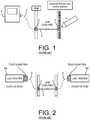
- a tone generatorthat generates an electrical signal either at an audible frequency or a higher frequency and with or without some form of modulation designed to carry information.
- This signalemanates from a connector on the tone generator 1 as shown in FIG. 1 .
- the signalis coupled onto a cable 4 that is to be traced via an intermediate cable 2 that is connected between the tone generator 1 and a connector 3 that is positioned at one end of the cable 4 to be tested.
- a hand held probe 6is then used to find the other end of the cable 4 by attempting to receive the applied signal at one or more connections on a patch panel 5 .
- the tone signalis received by the probe 6 , following signal processing and amplification, the received tone is presented to the operator by the probe 6 as an audible and or visual display of signal strength.
- the cable 4 that the user is attempting to tracecan then be identified as being the cable that is terminated at the socket presenting the highest signal strength when the probe 6 is coupled to each of the multiple sockets of the patch panel 5 .
- the next operation in the test sequencerequires the tone generator 1 and the intermediate cable 2 to be disconnected and replaced with one part of a LAN tester 6 A as shown in FIG. 2 .
- the LAN tester 6 Ais connected via use of test adaptor and a special patch cable 9 as further shown in FIG. 2 .
- the other part of the LAN tester 6 Bis then connected by a second test adaptor and another special patch cable 9 to the socket in the patch panel 5 identified in the first steps described above. In this manner, the complete circuit may now be tested by the pair of LAN Testers as required.
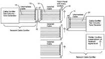
- the systemincludes a first device having a first cable certification and test circuitry which is couplable to the first connector and a second device having a second cable certification and test circuitry which is couplable to the second connector.
- One of the first device and the second devicefurther includes circuitry for generating a tone signal that is to be applied to the cable and the other one of the first device and the second device further includes a probe for receiving the tone signal and for generating an output indicative of a strength of the received tone signal.
- FIG. 1illustrates a prior art system and method for using a “tone and probe” system to trace network and communications cables;
- FIG. 2illustrates a prior art system and method for using LAN testers to test a traced network or communications cable
- FIG. 3illustrates the subject, improved system and method for tracing and testing network and communication cables.
- the described system and methodis intended to assist an operator, who is connecting some specific test equipment (e.g. a network cable certifier) to the two ends of a cable to be tested, in further identifying the exact connectors to be used. While it continues to be necessary to identify the specific connector, e.g., socket, that terminates the cable to be tested on a panel of many connectors, rather than moving a dedicated probe across the front of these sockets, as described above in connection with prior art FIG. 1 , and then replacing the tone generator at the one end of the cable with the first part of the network cable certifier equipment and then plugging in the cable to the second part of the network cable certifier, as described above in connection with prior art FIG.
- some specific test equipmente.g. a network cable certifier
- the connector 10 on the end of an intermediate cable 15 that is coupled to the tone generator/network cable certifieris coupled with an end of an installed cable 17 , which end terminates at a connector 16 .
- the other end of the cable 17is typically fitted into a patch panel containing many termination connectors 19 , one of which provides the termination for the cable 17 .
- a connector 11 on the end of an intermediate cable 21 that is coupled to a network cable certifier, which also has associated therewith probe circuitrymay be placed into communication with the termination connectors 19 of the patch panel to thereby allow the cable 17 to be traced.
- the circuitry inside the right hand (as shown in FIG. 3 ) network cable certifierwill be capable of receiving a signal (if any) from a connector 19 (where the signal is generated by the left hand tone generator/network cable certifier coupled to the cable 11 ) whereupon the received signal will be processed in a similar way to a normal probe as described above.
- an operatorFor tracing the cable, an operator is intended to move the connector 11 into at least close proximity to each of the connectors 19 , e.g., sockets, on the patch panel, in turn, whereupon the right hand network cable certifier will be able to indicate the received signal strength (of the connector 19 currently under test) audibly, mechanically (e.g., via vibration), and/or visibly to the operator including, possibly, by have one of these indicators attached to or combined into the connector 11 .
- the connector 19 exhibiting the highest received signal strengthwill be the one connected to the left hand network cable certifier at the other end of the cable, so both ends of the cable 17 to be tested have been identified. It is now only necessary to directly couple the connector 11 with the appropriate connector 19 , e.g., insert the connector 11 into the socket at which the traced cable terminates, and testing of the installed cable can begin using the same equipment.
- a key advantage of this described designis that it simplifies and speeds up the identification of a specific connector located with many others and so allows testing to begin more quickly.
- the same proceduremay be performed in the reverse direction, so that the remote network cable certifier is the tone generator and the display end network cable certifier cable connector is used as a probe.
- the probe circuitry and/or the devices for providing an indication of received signal strengthcan be incorporated into the socket connector of the intermediate cable that is to be coupled to the cable certifier.
- the particular concepts disclosedare meant to be illustrative only and not limiting as to the scope of the invention which is to be given the full breadth of the appended claims and any equivalents thereof.
Landscapes
- Physics & Mathematics (AREA)
- General Physics & Mathematics (AREA)
- Engineering & Computer Science (AREA)
- Signal Processing (AREA)
- Computer Networks & Wireless Communication (AREA)
- Testing Of Short-Circuits, Discontinuities, Leakage, Or Incorrect Line Connections (AREA)
- Details Of Connecting Devices For Male And Female Coupling (AREA)
Abstract
Description
Claims (11)
Priority Applications (1)
| Application Number | Priority Date | Filing Date | Title |
|---|---|---|---|
| US15/891,544US10591528B2 (en) | 2017-02-14 | 2018-02-08 | System and method for using a connector at the end of a cable as a cable locating tone sensor |
Applications Claiming Priority (2)
| Application Number | Priority Date | Filing Date | Title |
|---|---|---|---|
| US201762458662P | 2017-02-14 | 2017-02-14 | |
| US15/891,544US10591528B2 (en) | 2017-02-14 | 2018-02-08 | System and method for using a connector at the end of a cable as a cable locating tone sensor |
Publications (2)
| Publication Number | Publication Date |
|---|---|
| US20190049505A1 US20190049505A1 (en) | 2019-02-14 |
| US10591528B2true US10591528B2 (en) | 2020-03-17 |
Family
ID=63170723
Family Applications (1)
| Application Number | Title | Priority Date | Filing Date |
|---|---|---|---|
| US15/891,544Expired - Fee RelatedUS10591528B2 (en) | 2017-02-14 | 2018-02-08 | System and method for using a connector at the end of a cable as a cable locating tone sensor |
Country Status (3)
| Country | Link |
|---|---|
| US (1) | US10591528B2 (en) |
| EP (1) | EP3583433A4 (en) |
| WO (1) | WO2018151997A1 (en) |
Cited By (1)
| Publication number | Priority date | Publication date | Assignee | Title |
|---|---|---|---|---|
| US11428751B1 (en) | 2022-02-03 | 2022-08-30 | Starburst Industries LLC | Cable verification system for telecommunication cables |
Citations (19)
| Publication number | Priority date | Publication date | Assignee | Title |
|---|---|---|---|---|
| US5457441A (en) | 1993-06-04 | 1995-10-10 | Progressive Electronics, Inc. | Inductive amplifier having two-terminal auto-on function |
| US5574769A (en) | 1995-11-09 | 1996-11-12 | Progressive Electronics, Inc. | Inductive amplifier having automatic gain control for butt set |
| US5577009A (en) | 1994-01-25 | 1996-11-19 | Matsushita Electric Industrial Co., Ltd. | Tracking control system for generating a variable still jump signal |
| US5703928A (en) | 1995-09-26 | 1997-12-30 | Industrial Technology, Inc. | Probe for sampling differential electromagnetic fields |
| US5909113A (en) | 1993-06-04 | 1999-06-01 | Progressive Electronic, Inc. | Inductive amplifier having recessed butt set leads |
| US20030071634A1 (en) | 2001-10-16 | 2003-04-17 | Johnson Darrell J. | Tone generator and probe |
| US20040113604A1 (en) | 2002-12-12 | 2004-06-17 | Renken Gerald W. | Hand-held tester and method for local area network cabling |
| US6798183B2 (en) | 2002-06-04 | 2004-09-28 | Fluke Corporation | Method of and apparatus for simultaneously providing tone and intermittent link onto a cable to assist identifying the cable |
| US6946850B2 (en) | 2001-10-25 | 2005-09-20 | Tempo Research Corporation | Method and apparatus for filtering unwanted noise while amplifying a desired signal |
| USD512333S1 (en) | 2004-04-29 | 2005-12-06 | Fluke Corporation | Digital toning instrument |
| US7026803B2 (en) | 2002-09-30 | 2006-04-11 | Michael Kurth | Hand-held, ergonomic capacitive amplifier and hand-held tone generator to be used in conjunction with the capacitive amplifier |
| US20070127627A1 (en)* | 2005-09-22 | 2007-06-07 | Kern Joseph F Jr | Line tone adapter for a cable test system |
| US7242178B2 (en) | 2003-09-30 | 2007-07-10 | Fluke Corporation | Digital cable toning apparatus and method |
| US20090061678A1 (en)* | 2007-09-04 | 2009-03-05 | Apple Inc. | Smart Cables |
| US20120290246A1 (en)* | 2011-05-13 | 2012-11-15 | Anuj Bhatnagar | Test systems with cables that support multiple communications buses |
| US20120306631A1 (en) | 2011-06-03 | 2012-12-06 | Apple Inc. | Audio Conversion To Vibration Patterns |
| US20130234725A1 (en) | 2012-03-12 | 2013-09-12 | Commscope, Inc. Of North Carolina | Intelligent Patching Systems and Methods Using Electrical Cable Diagnostic Tests and Inference-Based Mapping Techniques |
| US20160356670A1 (en)* | 2015-06-04 | 2016-12-08 | Fluke Corporation | System and method for certification of physical parameters of communication links |
| US20160381123A1 (en)* | 2013-03-29 | 2016-12-29 | WOW Insites LLC | Electronic Testing Device |
Family Cites Families (1)
| Publication number | Priority date | Publication date | Assignee | Title |
|---|---|---|---|---|
| WO2012033769A1 (en)* | 2010-09-06 | 2012-03-15 | Psiber Data Pte. Ltd. | System and apparatus for testing cable |
- 2018
- 2018-02-08USUS15/891,544patent/US10591528B2/ennot_activeExpired - Fee Related
- 2018-02-08EPEP18753975.4Apatent/EP3583433A4/ennot_activeWithdrawn
- 2018-02-08WOPCT/US2018/017361patent/WO2018151997A1/ennot_activeCeased
Patent Citations (22)
| Publication number | Priority date | Publication date | Assignee | Title |
|---|---|---|---|---|
| US5457441A (en) | 1993-06-04 | 1995-10-10 | Progressive Electronics, Inc. | Inductive amplifier having two-terminal auto-on function |
| US5909113A (en) | 1993-06-04 | 1999-06-01 | Progressive Electronic, Inc. | Inductive amplifier having recessed butt set leads |
| US5577009A (en) | 1994-01-25 | 1996-11-19 | Matsushita Electric Industrial Co., Ltd. | Tracking control system for generating a variable still jump signal |
| US5703928A (en) | 1995-09-26 | 1997-12-30 | Industrial Technology, Inc. | Probe for sampling differential electromagnetic fields |
| US5574769A (en) | 1995-11-09 | 1996-11-12 | Progressive Electronics, Inc. | Inductive amplifier having automatic gain control for butt set |
| US6707305B2 (en) | 2001-10-16 | 2004-03-16 | Psiber Data Systems Inc. | Tone generator and probe |
| US20030071634A1 (en) | 2001-10-16 | 2003-04-17 | Johnson Darrell J. | Tone generator and probe |
| US7116093B2 (en) | 2001-10-16 | 2006-10-03 | Psibor Data Systems, Inc. | Tone generator and probe |
| US6946850B2 (en) | 2001-10-25 | 2005-09-20 | Tempo Research Corporation | Method and apparatus for filtering unwanted noise while amplifying a desired signal |
| US6798183B2 (en) | 2002-06-04 | 2004-09-28 | Fluke Corporation | Method of and apparatus for simultaneously providing tone and intermittent link onto a cable to assist identifying the cable |
| US7026803B2 (en) | 2002-09-30 | 2006-04-11 | Michael Kurth | Hand-held, ergonomic capacitive amplifier and hand-held tone generator to be used in conjunction with the capacitive amplifier |
| US20040113604A1 (en) | 2002-12-12 | 2004-06-17 | Renken Gerald W. | Hand-held tester and method for local area network cabling |
| US7242178B2 (en) | 2003-09-30 | 2007-07-10 | Fluke Corporation | Digital cable toning apparatus and method |
| US7598721B2 (en) | 2003-09-30 | 2009-10-06 | Fluke Corporation | Locating a cable using synchronization portion and data portion of a tone packet of a system |
| USD512333S1 (en) | 2004-04-29 | 2005-12-06 | Fluke Corporation | Digital toning instrument |
| US20070127627A1 (en)* | 2005-09-22 | 2007-06-07 | Kern Joseph F Jr | Line tone adapter for a cable test system |
| US20090061678A1 (en)* | 2007-09-04 | 2009-03-05 | Apple Inc. | Smart Cables |
| US20120290246A1 (en)* | 2011-05-13 | 2012-11-15 | Anuj Bhatnagar | Test systems with cables that support multiple communications buses |
| US20120306631A1 (en) | 2011-06-03 | 2012-12-06 | Apple Inc. | Audio Conversion To Vibration Patterns |
| US20130234725A1 (en) | 2012-03-12 | 2013-09-12 | Commscope, Inc. Of North Carolina | Intelligent Patching Systems and Methods Using Electrical Cable Diagnostic Tests and Inference-Based Mapping Techniques |
| US20160381123A1 (en)* | 2013-03-29 | 2016-12-29 | WOW Insites LLC | Electronic Testing Device |
| US20160356670A1 (en)* | 2015-06-04 | 2016-12-08 | Fluke Corporation | System and method for certification of physical parameters of communication links |
Non-Patent Citations (1)
| Title |
|---|
| ISA/US, Int. Search Report and Written Opinion issued on PCT application No. US18/17361, dated May 21, 2018, 9 pages. |
Cited By (1)
| Publication number | Priority date | Publication date | Assignee | Title |
|---|---|---|---|---|
| US11428751B1 (en) | 2022-02-03 | 2022-08-30 | Starburst Industries LLC | Cable verification system for telecommunication cables |
Also Published As
| Publication number | Publication date |
|---|---|
| EP3583433A1 (en) | 2019-12-25 |
| WO2018151997A1 (en) | 2018-08-23 |
| EP3583433A4 (en) | 2020-08-05 |
| US20190049505A1 (en) | 2019-02-14 |
Similar Documents
| Publication | Publication Date | Title |
|---|---|---|
| US11592464B2 (en) | Universal mate-in cable interface system | |
| US9921260B2 (en) | Voltage indicator with continuity check | |
| EP1387176A2 (en) | Time-domain reflectometer for testing terminated network cable | |
| US20160068073A1 (en) | DC Fast Charge Testing Method and System for Electric Vehicles | |
| JPH02504190A (en) | Portable identification device for communication cables | |
| US11543464B2 (en) | Wire harness test device and method for verifying connections when assembling a wire harness | |
| CN103163561A (en) | Cable path electriferous probing method and device | |
| KR101151885B1 (en) | Cable access device and the system for testing conductive sensitivity using the same | |
| US6798183B2 (en) | Method of and apparatus for simultaneously providing tone and intermittent link onto a cable to assist identifying the cable | |
| JPH0868821A (en) | Continuity tester for multiple electric wires | |
| US10591528B2 (en) | System and method for using a connector at the end of a cable as a cable locating tone sensor | |
| CN107465915B (en) | Fault detection device and system | |
| CN211878149U (en) | Portable aircraft complete machine cable conduction testing device | |
| US20120270436A1 (en) | Identifying individual copper network cables on a patch panel | |
| US10476778B2 (en) | LAN testing system | |
| CN102803976B (en) | Power cord detection systems and electrical connectors | |
| CN110988589A (en) | Aircraft engine cable intermittent fault detector and detection method | |
| CN203714184U (en) | Testing system of navigation device | |
| CN203881892U (en) | Cable loss measurement device | |
| SI22426A (en) | Measurement device for checking the wiring of low-voltage electrical wiring | |
| US10802052B2 (en) | Circuit multi-tester including phase rotation-measurement circuitry | |
| CN114280496B (en) | Diagnostic device and diagnostic method | |
| JP2015129648A (en) | Test system and test method | |
| KR100570918B1 (en) | Seismic recorder and seismic sensor cable inspection device | |
| CN205880118U (en) | Medical line ID identification device |
Legal Events
| Date | Code | Title | Description |
|---|---|---|---|
| FEPP | Fee payment procedure | Free format text:ENTITY STATUS SET TO UNDISCOUNTED (ORIGINAL EVENT CODE: BIG.); ENTITY STATUS OF PATENT OWNER: LARGE ENTITY | |
| AS | Assignment | Owner name:IDEAL INDUSTRIES, INC., ILLINOIS Free format text:ASSIGNMENT OF ASSIGNORS INTEREST;ASSIGNORS:MERCER, IAN;KENT, PETER;REEL/FRAME:044894/0182 Effective date:20180209 | |
| STPP | Information on status: patent application and granting procedure in general | Free format text:DOCKETED NEW CASE - READY FOR EXAMINATION | |
| AS | Assignment | Owner name:IDEAL INDUSTRIES NETWORKS LIMITED, UNITED KINGDOM Free format text:NUNC PRO TUNC ASSIGNMENT;ASSIGNOR:IDEAL INDUSTRIES, INC.;REEL/FRAME:049056/0899 Effective date:20190425 | |
| STPP | Information on status: patent application and granting procedure in general | Free format text:NON FINAL ACTION MAILED | |
| STPP | Information on status: patent application and granting procedure in general | Free format text:RESPONSE TO NON-FINAL OFFICE ACTION ENTERED AND FORWARDED TO EXAMINER | |
| STPP | Information on status: patent application and granting procedure in general | Free format text:NOTICE OF ALLOWANCE MAILED -- APPLICATION RECEIVED IN OFFICE OF PUBLICATIONS | |
| STPP | Information on status: patent application and granting procedure in general | Free format text:PUBLICATIONS -- ISSUE FEE PAYMENT VERIFIED | |
| STCF | Information on status: patent grant | Free format text:PATENTED CASE | |
| FEPP | Fee payment procedure | Free format text:MAINTENANCE FEE REMINDER MAILED (ORIGINAL EVENT CODE: REM.); ENTITY STATUS OF PATENT OWNER: LARGE ENTITY | |
| LAPS | Lapse for failure to pay maintenance fees | Free format text:PATENT EXPIRED FOR FAILURE TO PAY MAINTENANCE FEES (ORIGINAL EVENT CODE: EXP.); ENTITY STATUS OF PATENT OWNER: LARGE ENTITY | |
| STCH | Information on status: patent discontinuation | Free format text:PATENT EXPIRED DUE TO NONPAYMENT OF MAINTENANCE FEES UNDER 37 CFR 1.362 | |
| FP | Lapsed due to failure to pay maintenance fee | Effective date:20240317 |