US10590925B2 - Control system and method for reciprocating compressors - Google Patents
Control system and method for reciprocating compressorsDownload PDFInfo
- Publication number
- US10590925B2 US10590925B2US13/982,126US201213982126AUS10590925B2US 10590925 B2US10590925 B2US 10590925B2US 201213982126 AUS201213982126 AUS 201213982126AUS 10590925 B2US10590925 B2US 10590925B2
- Authority
- US
- United States
- Prior art keywords
- velocity
- rotation turn
- compression mechanism
- braking torque
- mechanical assembly
- Prior art date
- Legal status (The legal status is an assumption and is not a legal conclusion. Google has not performed a legal analysis and makes no representation as to the accuracy of the status listed.)
- Active, expires
Links
- 238000000034methodMethods0.000titleclaimsdescription20
- 238000001816coolingMethods0.000claimsabstractdescription13
- 238000007906compressionMethods0.000claimsdescription47
- 230000006835compressionEffects0.000claimsdescription44
- 230000007246mechanismEffects0.000claimsdescription33
- 230000033001locomotionEffects0.000claimsdescription22
- 239000000725suspensionSubstances0.000description13
- 239000007789gasSubstances0.000description8
- 239000000112cooling gasSubstances0.000description6
- 238000006243chemical reactionMethods0.000description5
- 230000035939shockEffects0.000description5
- 238000006073displacement reactionMethods0.000description4
- 230000003247decreasing effectEffects0.000description2
- 238000001514detection methodMethods0.000description2
- 238000004519manufacturing processMethods0.000description2
- 230000001052transient effectEffects0.000description2
- 238000004804windingMethods0.000description2
- 230000005534acoustic noiseEffects0.000description1
- 230000005540biological transmissionEffects0.000description1
- 238000009833condensationMethods0.000description1
- 230000005494condensationEffects0.000description1
- 125000004122cyclic groupChemical group0.000description1
- 238000013016dampingMethods0.000description1
- 230000001419dependent effectEffects0.000description1
- 238000001704evaporationMethods0.000description1
- 230000008020evaporationEffects0.000description1
- 238000001914filtrationMethods0.000description1
- 238000005457optimizationMethods0.000description1
- 230000010355oscillationEffects0.000description1
- 238000005086pumpingMethods0.000description1
Images


Classifications
- F—MECHANICAL ENGINEERING; LIGHTING; HEATING; WEAPONS; BLASTING
- F04—POSITIVE - DISPLACEMENT MACHINES FOR LIQUIDS; PUMPS FOR LIQUIDS OR ELASTIC FLUIDS
- F04B—POSITIVE-DISPLACEMENT MACHINES FOR LIQUIDS; PUMPS
- F04B49/00—Control, e.g. of pump delivery, or pump pressure of, or safety measures for, machines, pumps, or pumping installations, not otherwise provided for, or of interest apart from, groups F04B1/00 - F04B47/00
- F04B49/06—Control using electricity
- F—MECHANICAL ENGINEERING; LIGHTING; HEATING; WEAPONS; BLASTING
- F04—POSITIVE - DISPLACEMENT MACHINES FOR LIQUIDS; PUMPS FOR LIQUIDS OR ELASTIC FLUIDS
- F04B—POSITIVE-DISPLACEMENT MACHINES FOR LIQUIDS; PUMPS
- F04B35/00—Piston pumps specially adapted for elastic fluids and characterised by the driving means to their working members, or by combination with, or adaptation to, specific driving engines or motors, not otherwise provided for
- F04B35/04—Piston pumps specially adapted for elastic fluids and characterised by the driving means to their working members, or by combination with, or adaptation to, specific driving engines or motors, not otherwise provided for the means being electric
- F—MECHANICAL ENGINEERING; LIGHTING; HEATING; WEAPONS; BLASTING
- F04—POSITIVE - DISPLACEMENT MACHINES FOR LIQUIDS; PUMPS FOR LIQUIDS OR ELASTIC FLUIDS
- F04B—POSITIVE-DISPLACEMENT MACHINES FOR LIQUIDS; PUMPS
- F04B49/00—Control, e.g. of pump delivery, or pump pressure of, or safety measures for, machines, pumps, or pumping installations, not otherwise provided for, or of interest apart from, groups F04B1/00 - F04B47/00
- F04B49/02—Stopping, starting, unloading or idling control
- F—MECHANICAL ENGINEERING; LIGHTING; HEATING; WEAPONS; BLASTING
- F04—POSITIVE - DISPLACEMENT MACHINES FOR LIQUIDS; PUMPS FOR LIQUIDS OR ELASTIC FLUIDS
- F04B—POSITIVE-DISPLACEMENT MACHINES FOR LIQUIDS; PUMPS
- F04B49/00—Control, e.g. of pump delivery, or pump pressure of, or safety measures for, machines, pumps, or pumping installations, not otherwise provided for, or of interest apart from, groups F04B1/00 - F04B47/00
- F04B49/06—Control using electricity
- F04B49/065—Control using electricity and making use of computers
- F—MECHANICAL ENGINEERING; LIGHTING; HEATING; WEAPONS; BLASTING
- F04—POSITIVE - DISPLACEMENT MACHINES FOR LIQUIDS; PUMPS FOR LIQUIDS OR ELASTIC FLUIDS
- F04B—POSITIVE-DISPLACEMENT MACHINES FOR LIQUIDS; PUMPS
- F04B49/00—Control, e.g. of pump delivery, or pump pressure of, or safety measures for, machines, pumps, or pumping installations, not otherwise provided for, or of interest apart from, groups F04B1/00 - F04B47/00
- F04B49/10—Other safety measures
- F04B49/103—Responsive to speed
- F—MECHANICAL ENGINEERING; LIGHTING; HEATING; WEAPONS; BLASTING
- F04—POSITIVE - DISPLACEMENT MACHINES FOR LIQUIDS; PUMPS FOR LIQUIDS OR ELASTIC FLUIDS
- F04B—POSITIVE-DISPLACEMENT MACHINES FOR LIQUIDS; PUMPS
- F04B49/00—Control, e.g. of pump delivery, or pump pressure of, or safety measures for, machines, pumps, or pumping installations, not otherwise provided for, or of interest apart from, groups F04B1/00 - F04B47/00
- F04B49/20—Control, e.g. of pump delivery, or pump pressure of, or safety measures for, machines, pumps, or pumping installations, not otherwise provided for, or of interest apart from, groups F04B1/00 - F04B47/00 by changing the driving speed
- F—MECHANICAL ENGINEERING; LIGHTING; HEATING; WEAPONS; BLASTING
- F04—POSITIVE - DISPLACEMENT MACHINES FOR LIQUIDS; PUMPS FOR LIQUIDS OR ELASTIC FLUIDS
- F04B—POSITIVE-DISPLACEMENT MACHINES FOR LIQUIDS; PUMPS
- F04B2201/00—Pump parameters
- F04B2201/02—Piston parameters
- F04B2201/0201—Position of the piston
- F—MECHANICAL ENGINEERING; LIGHTING; HEATING; WEAPONS; BLASTING
- F04—POSITIVE - DISPLACEMENT MACHINES FOR LIQUIDS; PUMPS FOR LIQUIDS OR ELASTIC FLUIDS
- F04B—POSITIVE-DISPLACEMENT MACHINES FOR LIQUIDS; PUMPS
- F04B2201/00—Pump parameters
- F04B2201/02—Piston parameters
- F04B2201/0209—Duration of piston stroke
- F—MECHANICAL ENGINEERING; LIGHTING; HEATING; WEAPONS; BLASTING
- F04—POSITIVE - DISPLACEMENT MACHINES FOR LIQUIDS; PUMPS FOR LIQUIDS OR ELASTIC FLUIDS
- F04B—POSITIVE-DISPLACEMENT MACHINES FOR LIQUIDS; PUMPS
- F04B2201/00—Pump parameters
- F04B2201/08—Cylinder or housing parameters
- F04B2201/0802—Vibration
- F—MECHANICAL ENGINEERING; LIGHTING; HEATING; WEAPONS; BLASTING
- F04—POSITIVE - DISPLACEMENT MACHINES FOR LIQUIDS; PUMPS FOR LIQUIDS OR ELASTIC FLUIDS
- F04B—POSITIVE-DISPLACEMENT MACHINES FOR LIQUIDS; PUMPS
- F04B2201/00—Pump parameters
- F04B2201/12—Parameters of driving or driven means
- F04B2201/1201—Rotational speed of the axis
- F—MECHANICAL ENGINEERING; LIGHTING; HEATING; WEAPONS; BLASTING
- F04—POSITIVE - DISPLACEMENT MACHINES FOR LIQUIDS; PUMPS FOR LIQUIDS OR ELASTIC FLUIDS
- F04B—POSITIVE-DISPLACEMENT MACHINES FOR LIQUIDS; PUMPS
- F04B2201/00—Pump parameters
- F04B2201/12—Parameters of driving or driven means
- F04B2201/127—Braking parameters
- F—MECHANICAL ENGINEERING; LIGHTING; HEATING; WEAPONS; BLASTING
- F05—INDEXING SCHEMES RELATING TO ENGINES OR PUMPS IN VARIOUS SUBCLASSES OF CLASSES F01-F04
- F05B—INDEXING SCHEME RELATING TO WIND, SPRING, WEIGHT, INERTIA OR LIKE MOTORS, TO MACHINES OR ENGINES FOR LIQUIDS COVERED BY SUBCLASSES F03B, F03D AND F03G
- F05B2210/00—Working fluid
- F05B2210/10—Kind or type
- F05B2210/12—Kind or type gaseous, i.e. compressible
- Y—GENERAL TAGGING OF NEW TECHNOLOGICAL DEVELOPMENTS; GENERAL TAGGING OF CROSS-SECTIONAL TECHNOLOGIES SPANNING OVER SEVERAL SECTIONS OF THE IPC; TECHNICAL SUBJECTS COVERED BY FORMER USPC CROSS-REFERENCE ART COLLECTIONS [XRACs] AND DIGESTS
- Y10—TECHNICAL SUBJECTS COVERED BY FORMER USPC
- Y10S—TECHNICAL SUBJECTS COVERED BY FORMER USPC CROSS-REFERENCE ART COLLECTIONS [XRACs] AND DIGESTS
- Y10S415/00—Rotary kinetic fluid motors or pumps
- Y—GENERAL TAGGING OF NEW TECHNOLOGICAL DEVELOPMENTS; GENERAL TAGGING OF CROSS-SECTIONAL TECHNOLOGIES SPANNING OVER SEVERAL SECTIONS OF THE IPC; TECHNICAL SUBJECTS COVERED BY FORMER USPC CROSS-REFERENCE ART COLLECTIONS [XRACs] AND DIGESTS
- Y10—TECHNICAL SUBJECTS COVERED BY FORMER USPC
- Y10S—TECHNICAL SUBJECTS COVERED BY FORMER USPC CROSS-REFERENCE ART COLLECTIONS [XRACs] AND DIGESTS
- Y10S417/00—Pumps
Definitions
- the present inventionrelates to a system and a method that enable one to control the stopping (braking) behavior of a reciprocating compressor.
- Hermitic compressor of reciprocating typecomprise rod-crank-and-piston type with reciprocating movement and are widely used in the cooling-equipment, household and commercial industry.
- Reciprocating compressorsmay be of the fixed-capacity type, wherein the control of two fixed-velocity states (ON/OFF) is carried out upon turning on the compressor at a maximum temperature and turning off the compressor at a minimum temperature, or varying-capacity compressors, wherein the control is carried out by some electromechanical device or electronic circuit, capable of responding to a programming dependent upon variables to be controlled on the cooling equipment, as for instance the inner temperature of the compartments, wherein the compressor acts in reciprocating operation cycles at varying velocities and stop.
- the reciprocating compressorsare responsible for circulating the cooling gas through the cooling circuit, the rod-crank-and-piston mechanism being responsible for carrying out cyclic movements in which the piston raises the gas pressure during its advance and the cooling gas applied a contrary stress onto the mechanism and to the turning axle.
- This stress on the piston and the consequent reaction on the mechanism and turning axlevaries significantly throughout a turn of the turning axle, the variation being directly proportional to the values of cooling-gas pressure (the greater the difference between the pressures of evaporation and of condensation of the cooling circuit, the greater it is).
- the mechanismstill turns due to the inertia of the assembly, mainly the inertia of the motor rotor, which imposes the turning movement.
- the inertia movementcauses a jolt during the stopping of the compressor due to a contrary impulse on the piston, caused by the different in pressure of the gas.
- the impulseis caused by the abrupt stopping of the axle or by the turning movement in an opposite direction at the last turn of the axle because the piston is not capable of overcoming the pressure.
- the gasis compressed and uncompressed in an alternating movement, which may cause problems to the reciprocating compressor.
- the stopping joltis typical in reciprocating compressors for cooling.
- suspension-spring systems inside the compressorwhich support the whole assembly, so as to absorb impulses and attenuate them, and not cause problems, such as spring breaks or stopping noises due to shocks between parts.
- the main function of the suspension springsis to attenuate the transmission of the vibrations generated during the normal operation in the pumping system due to the reciprocating movement of the piston, thus preventing these vibrations from passing on to the outer compressor body and, as a result, to the cooler, which causes noises.
- the springsshould then be soft enough to attenuate the normal-functioning vibration, besides absorbing the stopping impulse.
- the springsshould not be designed to be excessively soft to the point of allowing a long displacement of the assembly during this stopping impulse, since this may cause shocks at the mechanical stops, raising noises.
- the designshould be adopted so as not to cause excessive stress on the springs to the point of causing fatigue or breakage thereof.
- a further objective of this inventionis to provide a system and a method that are capable of enabling the compressor to operate in conditions of high difference in pressure, under which it can be turned off without undesired impacts and noises being generated.
- a control system for cooling compressorscomprising at least one electronic control and one reciprocating compressor, which comprises at least one mechanical assembly that has at least one compression mechanism and one motor, the control system being configured to detect a rotation velocity of the compression mechanism and apply a braking torque to the mechanical assembly after detecting that the turning velocity is below a velocity level.
- FIG. 1represents of a cooling system
- FIG. 2represents of the control of a compressor, as well as the main subsystems inside the compressor;
- FIG. 3represents of details of the mechanical subsystem of a reciprocating compressor
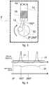
- FIG. 4represents of the compression process and of the velocity of the axle of a compressor
- FIG. 5representsation of the compression process and of the velocity of the axle of a compressor during the start according to the state of the art.
- FIG. 6representsation of the compression process and of the velocity of the axle of a compressor during the start according to the present invention.
- a cooling systemcomprises a reciprocating compressor 3 , which is fed by an electric power network 1 and has an electronic controller 2 capable of controlling the operation of a reciprocating compressor 3 .
- the reciprocating compressor 3drives a cooling gas in a gas-circulation closed circuit 18 , creating a cooling-gas flow 78 inside this circuit, directing the gas to a condenser 5 .
- the cooling gasgoes though a flow-cooling device 6 , which may be, for instance, a cappillary tube. Then, the gas is led to an evaporator 4 and later returns to the reciprocating compressor 3 , restarting the gas-circulation circuit.
- FIG. 2illustrates a focus in subsystems inside the reciprocating compressor, the reciprocating compressor 3 being formed by a housing 17 , suspension springs 11 that are responsible for damping the mechanical vibration generated by the movement of a mechanical assembly 12 , formed by the motor 9 and the compression mechanisms 8 , which are interconnected mechanically by the axle 10 that transmits torque and rotary motion.
- the mechanical vibrations generated by the compression mechanism 8due to the unbalancing and torque variation, are filtered by the suspension springs 11 .
- the suspension springs 11are projected so as to have a low elasticity coefficient (that is, as soft as possible), in order to increase the effectiveness of vibration filtration.
- this designincreases the amplitude of the oscillation transient and displacement of the mechanical assembly 12 during the stop of the reciprocating compressor 3 , if the suspension springs 11 are made to soft, being capable of causing mechanical shocks between the mechanical assembly 12 (drive and compression) against the housing 17 of the reciprocating compressor 3 , generating acoustic noise and possible fatigues or breaks of the suspension springs 11 .
- FIG. 3shows the compression mechanism 8 , which comprises a turning axle 10 , to which the rod 16 is coupled.
- the rod 16modifies the rotary motion of the turning axle 10 during the reciprocating motion, which drives a piston 15 to move inside a cylinder 13 , causing the compressed gas to circulate through a valve plate 14 .
- This mechanismcompresses the gas, so that high differences in pressure and high reaction torque peaks are generated.
- the rotary motion of the turning axle 10is kept by its own inertia, its average velocity being maintained by the production of torque by the motor 9 .
- FIG. 4presents an operation torque 20 , generated by the motor 9 , which encounters a reaction torque 21 of the compression mechanism 8 , configured to cause a variation of a turning velocity 23 of the turning axle 10 of the reciprocating compressor 3 .
- This turning velocity 23 of the turning axle 10varies throughout a compression cycle, which begins at the lower dead point of the piston 15 , generally when the turn angle is zero, reaching the maximum compression and the maximum reaction torque 21 generally at a lower angle close to 180 degrees of turn, thus causing deceleration of the axle.
- the compression mechanism 8continues its inertia movement fed by the kinetic energy stored on the turning axle 10 , the turn velocity 23 of the turning axle 10 decreasing gradually with every compression cycle that is completed, extracting kinetic energy from the turning mass axle 10 , until the impulse moment 24 , when, due to the very reduced rotation of the turning axle thee is not sufficient energy to complete the compression cycle.
- the turning axle 10loses turn velocity 23 quickly, that it, a high deceleration (rpm/s) takes place, which causes a reverse impulse in the compression mechanism 8 at the impulse moment 24 .
- the deceleration of the compression mechanism 8in a very short period of time drives the whole mechanical assembly 12 and may cause the turning axle 10 to turn in the opposition direction.
- the kinetic energy of the turning axle 10depends on the rotation (squared) and on the inertia of the turning axle 10 .
- the reverse impulse that takes place at the abrupt stopcauses a strong impulse on the mechanical assembly 12 and, in this way, causes a large displacement and possible mechanical shock between mechanical assembly 12 and housing 17 , thus causing noise and fatigue of the suspension springs 11 .
- FIG. 6shows a graph according to the present invention, which shows the solution of the problems indicated, wherein, during the stopping process of the reciprocating compressor 3 , at the braking moment 32 when the motor 9 stops generating operation torque, the compression mechanism 8 continues its inertia movement fed by the kinetic energy stored on the turning axle 10 , the turn velocity 23 of the turning axle 10 decreasing gradually until the rotation of the turning axle 10 will be lower than a velocity level 34 .
- the electronic controller 2detects that the rotation of the turning axle 10 reaches the velocity level 34 , at the following moment 35 the electronic controller 2 applies a braking torque 36 in the opposite direction to the turn of the compression mechanism 8 .
- this detectionis made by the electronic control 2 , which detects the time between the changes of rotor position.
- the period of stroke of the piston(0° to 360°) varies in an inversely proportional way with respect to the velocity.
- the electronic control 2can be configured to detect the period which the compression mechanism 8 needs to carry out its movement (from 0° to 360°) and compare such a period with a maximum reference time.
- This maximum reference timeis related with the period which the compression mechanism 8 needs to carry out its movement at the velocity level 34 . In this way, one can state that the braking torque 36 is applied when the rotation velocity of the turning axle 10 is below a velocity level 34 that is predefined by the electronic control 2 .
- the braking torque 36is generally applied when the reaction torque 31 goes though one of its maximum values (peaks), to facilitate the braking by using the inertia of the motor 9 , which is already under deceleration.
- the most relevant aspects of this braking torque 36are its intensity, which depends on the level of current that will circulate through the windings of the motor 9 , and its duration, which may go from the moment when it reaches the velocity level 34 until complete stop of the motor 9 .
- the application of the braking torque 36may be made in various ways. Preferably one employs the methods of adding a resistance between the windings of the motor 9 , which causes the current generated by the movement of the motor 9 to circulate ion a closed circuit and generates a torque contrary to the motion (which may also be carried out by means of a PWM modulation of the inverter that controls the motor 9 ), or the application of a current contrary to that applied to the motor 9 when it is in operation.
- This following 35 following the velocity level 34comprises much of the last turn of the turning axle 10 , beginning a braking period 37 of the turning axle 10 . In this way, one prevents the last compression cycle from taking place, thus preventing also a strong reverse impulse on the compression mechanism 8 . In this way, the deceleration of the turning axle 10 takes place and is distributed throughout the last turn in a controlled manner, resulting in a deceleration value (rpm/s) that is substantially lower than the one observed in the present-day art.
- the rotation velocity level 34 of the turning axle 10should preferably be sufficient for the kinetic energy stored on the turning axle 10 of the reciprocating compression 3 to be capable of completing a complete compression cycle, thus preventing the sudden deceleration and jolt of the compression mechanism 8 .
- the present inventionenables the suspension springs 11 of the mechanism 12 to be designed so as to have low elasticity coefficient, being very effective to filter vibration, and still prevents shocks of the mechanical assembly 12 with the housing 17 of the reciprocating compressor 3 . Besides, the present invention prevents high displacement of this mechanical assembly 12 during the stopping transient, minimizing the mechanical stress and fatigue caused to the suspension springs 11 .
- the present inventiondefines a system and a method that reduces significantly (or even eliminates) jolts on the mechanical assembly of the compressor during its stop, by means of controlled deceleration of the rod-crank-and-piston assembly throughout the last turn of the turning axle, this preventing the piston from decelerating abruptly during the last incomplete gas compression cycle and also preventing the production of a high impulse with torque.
Landscapes
- Engineering & Computer Science (AREA)
- Mechanical Engineering (AREA)
- General Engineering & Computer Science (AREA)
- Computer Hardware Design (AREA)
- Control Of Positive-Displacement Pumps (AREA)
- Compressor (AREA)
- Control Of Positive-Displacement Air Blowers (AREA)
- Control Of Electric Motors In General (AREA)
Abstract
Description
Claims (16)
Applications Claiming Priority (4)
| Application Number | Priority Date | Filing Date | Title |
|---|---|---|---|
| BRPI1100026-0ABRPI1100026A2 (en) | 2011-01-26 | 2011-01-26 | reciprocal compressor system and control method |
| BR1100026 | 2011-01-26 | ||
| BRPI1100026-0 | 2011-01-26 | ||
| PCT/BR2012/000014WO2012100313A1 (en) | 2011-01-26 | 2012-01-25 | Control system and method for reciprocating compressors |
Publications (2)
| Publication Number | Publication Date |
|---|---|
| US20140072451A1 US20140072451A1 (en) | 2014-03-13 |
| US10590925B2true US10590925B2 (en) | 2020-03-17 |
Family
ID=45872751
Family Applications (1)
| Application Number | Title | Priority Date | Filing Date |
|---|---|---|---|
| US13/982,126Active2033-01-01US10590925B2 (en) | 2011-01-26 | 2012-01-25 | Control system and method for reciprocating compressors |
Country Status (12)
| Country | Link |
|---|---|
| US (1) | US10590925B2 (en) |
| EP (3) | EP2957770B1 (en) |
| JP (2) | JP6030576B2 (en) |
| KR (1) | KR20140004691A (en) |
| CN (3) | CN103403349B (en) |
| AR (1) | AR084928A1 (en) |
| BR (2) | BRPI1100026A2 (en) |
| DE (1) | DE202012013046U1 (en) |
| ES (2) | ES2551398T3 (en) |
| SG (1) | SG192003A1 (en) |
| TR (1) | TR201900678T4 (en) |
| WO (1) | WO2012100313A1 (en) |
Cited By (1)
| Publication number | Priority date | Publication date | Assignee | Title |
|---|---|---|---|---|
| US20210062797A1 (en)* | 2018-03-01 | 2021-03-04 | Secop Gmbh | System comprising a refrigerant compressor and method for operating the refrigerant compressor |
Families Citing this family (17)
| Publication number | Priority date | Publication date | Assignee | Title |
|---|---|---|---|---|
| BRPI1100026A2 (en) | 2011-01-26 | 2013-04-24 | Whirlpool Sa | reciprocal compressor system and control method |
| EP3054158A1 (en)* | 2015-02-09 | 2016-08-10 | Secop GmbH | Method for stopping a hermetic refrigerant compressor and control system for same |
| DE102015215972A1 (en) | 2015-08-21 | 2017-02-23 | BSH Hausgeräte GmbH | Domestic refrigeration appliance with a refrigerant circuit and method for operating a household refrigerator with a refrigerant circuit |
| DE102015221881A1 (en) | 2015-11-06 | 2017-05-11 | BSH Hausgeräte GmbH | Domestic refrigeration appliance with a refrigerant circuit and method for operating a household refrigerator with a refrigerant circuit |
| CN105370559B (en)* | 2015-12-03 | 2017-08-01 | 浙江工业大学 | Measuring device and method for no-load torque of reciprocating mechanical mechanism of refrigeration compressor |
| EP3199809B1 (en)* | 2016-01-28 | 2021-06-09 | ABB Schweiz AG | Control method for a compressor system |
| US10436226B2 (en)* | 2016-02-24 | 2019-10-08 | Emerson Climate Technologies, Inc. | Compressor having sound control system |
| EP3282126B1 (en) | 2016-03-30 | 2019-08-21 | Nidec Global Appliance Germany GmbH | Electronic control device for a refrigerant compressor |
| DE102016222958A1 (en) | 2016-11-22 | 2018-05-24 | BSH Hausgeräte GmbH | Method for stopping a reciprocating compressor and reciprocating compressor of a refrigeration device, air conditioner or a heat pump and refrigeration device, air conditioner or heat pump with it |
| WO2018114978A1 (en)* | 2016-12-19 | 2018-06-28 | Nidec Global Appliance Germany Gmbh | Control device and method for operating a refrigerant compressor |
| CN110300850B (en)* | 2016-12-19 | 2021-06-15 | 思科普有限公司 | Control device and method for operating a refrigerant compressor |
| JP6457684B1 (en)* | 2017-11-22 | 2019-01-23 | 新日本特機株式会社 | Brake torque generator for electric vehicle and electric vehicle |
| JP6331183B1 (en)* | 2017-11-22 | 2018-05-30 | 新日本特機株式会社 | Brake torque generator for electric vehicle and electric vehicle |
| BR102019027356A2 (en)* | 2019-12-19 | 2021-06-29 | Embraco Indústria De Compressores E Soluções Em Refrigeração Ltda. | NOISE REDUCTION METHOD AND SYSTEM AND PISTON POSITIONING IN ENGINE START FAILURE |
| KR102342001B1 (en)* | 2020-05-26 | 2021-12-24 | 어보브반도체 주식회사 | Control apparatus of compressor and method for controlling compressor |
| US12123803B2 (en)* | 2020-08-27 | 2024-10-22 | University Of Idaho | Rapid compression machine with electrical drive and methods for use thereof |
| CN116324168A (en)* | 2020-11-09 | 2023-06-23 | 海德鲁西昂公司 | Motor speed control system, device and method |
Citations (17)
| Publication number | Priority date | Publication date | Assignee | Title |
|---|---|---|---|---|
| US3540813A (en) | 1969-03-27 | 1970-11-17 | Bendix Westinghouse Automotive | Mounting support for hermetic motor compressors |
| US4355959A (en)* | 1979-10-26 | 1982-10-26 | Kabushiki Kaisha Toyoda Jidoshokki Seisakusho | Rotation sensor of a swash-plate type compressor |
| JPS60153483A (en) | 1984-01-20 | 1985-08-12 | Mitsubishi Heavy Ind Ltd | Method of stopping electric compressor |
| US5820349A (en) | 1995-09-14 | 1998-10-13 | Copeland Corporation | Rotary compressor with reverse rotating braking |
| US5986419A (en) | 1996-07-15 | 1999-11-16 | General Electric Company | Quadrature axis winding for sensorless rotor angular position control of single phase permanent magnet motor |
| US6121739A (en)* | 1996-12-23 | 2000-09-19 | Lang Apparatebau Gmbh | Dosing pump and method for enhancing dosing precision |
| JP2000287485A (en) | 1999-03-30 | 2000-10-13 | Toshiba Corp | Compressor motor control device for air conditioner |
| JP2001037281A (en) | 1999-05-18 | 2001-02-09 | Matsushita Electric Ind Co Ltd | Motor torque control device |
| US6544017B1 (en) | 2001-10-22 | 2003-04-08 | Tecumseh Products Company | Reverse rotation brake for scroll compressor |
| US20030180148A1 (en) | 2002-03-21 | 2003-09-25 | Kendro Laboratory Products, Inc. | Device for prevention of backward operation of scroll compressors |
| WO2004083744A1 (en) | 2003-03-17 | 2004-09-30 | Matsushita Electric Industrial Co. Ltd. | Air conditioner |
| JP2007092686A (en) | 2005-09-29 | 2007-04-12 | Sharp Corp | Compressor drive unit |
| US7300257B2 (en) | 2004-12-20 | 2007-11-27 | Carrier Corporation | Prevention of unpowered reverse rotation in compressors |
| US20090019835A1 (en)* | 2007-07-16 | 2009-01-22 | Dingle Philip J G | Fluid delivery system |
| US20100021313A1 (en)* | 2008-07-28 | 2010-01-28 | Eaton Corporation | Electronic control for a rotary fluid device |
| JP2010270700A (en) | 2009-05-22 | 2010-12-02 | Nissan Motor Co Ltd | Stop control device for compressor for fuel cell |
| EP2669519A1 (en) | 2011-01-26 | 2013-12-04 | Whirlpool S.A. | Control system and method for reciprocating compressors |
Family Cites Families (12)
| Publication number | Priority date | Publication date | Assignee | Title |
|---|---|---|---|---|
| US5220259A (en)* | 1991-10-03 | 1993-06-15 | Graco Inc. | Dc motor drive system and method |
| JPH07167076A (en) | 1993-12-17 | 1995-07-04 | Sanyo Electric Co Ltd | Electric motor-driven compression device |
| MY122977A (en) | 1995-03-14 | 2006-05-31 | Panasonic Corp | Refrigerating apparatus, and refrigerator control and brushless motor starter used in same |
| KR100414093B1 (en)* | 2001-08-01 | 2004-01-07 | 엘지전자 주식회사 | Velocity control apparatus for reciprocating compressor |
| KR100414095B1 (en)* | 2001-08-01 | 2004-01-07 | 엘지전자 주식회사 | Top dead center control apparatus for reciprocating compressor |
| JP3941452B2 (en)* | 2001-10-17 | 2007-07-04 | 株式会社豊田自動織機 | Operation stop control method and operation stop control device for vacuum pump |
| KR100480118B1 (en)* | 2002-10-04 | 2005-04-06 | 엘지전자 주식회사 | Stroke detecting apparatus and method for reciprocating compressor |
| JP2006112340A (en)* | 2004-10-15 | 2006-04-27 | Mitsubishi Heavy Ind Ltd | Pressure machine, method of suppressing vibration thereof, and fluid machine |
| JP4559241B2 (en)* | 2005-01-21 | 2010-10-06 | 株式会社神戸製鋼所 | Refrigeration equipment |
| US7922457B2 (en)* | 2005-02-26 | 2011-04-12 | Ingersoll-Rand Company | System and method for controlling a variable speed compressor during stopping |
| US20090092501A1 (en)* | 2007-10-08 | 2009-04-09 | Emerson Climate Technologies, Inc. | Compressor protection system and method |
| JP4940104B2 (en)* | 2007-10-30 | 2012-05-30 | 株式会社東芝 | Compressor control device |
- 2011
- 2011-01-26BRBRPI1100026-0Apatent/BRPI1100026A2/ennot_activeApplication Discontinuation
- 2012
- 2012-01-25BRBR112013018718-2Apatent/BR112013018718B1/enactiveIP Right Grant
- 2012-01-25DEDE202012013046.3Upatent/DE202012013046U1/ennot_activeExpired - Lifetime
- 2012-01-25EPEP15001898.4Apatent/EP2957770B1/enactiveActive
- 2012-01-25USUS13/982,126patent/US10590925B2/enactiveActive
- 2012-01-25CNCN201280006608.4Apatent/CN103403349B/enactiveActive
- 2012-01-25ESES12709775.6Tpatent/ES2551398T3/enactiveActive
- 2012-01-25WOPCT/BR2012/000014patent/WO2012100313A1/enactiveApplication Filing
- 2012-01-25JPJP2013550708Apatent/JP6030576B2/enactiveActive
- 2012-01-25SGSG2013054598Apatent/SG192003A1/enunknown
- 2012-01-25CNCN201610022973.4Apatent/CN105649930A/enactivePending
- 2012-01-25EPEP18206545.8Apatent/EP3462022B1/enactiveActive
- 2012-01-25KRKR1020137019503Apatent/KR20140004691A/ennot_activeAbandoned
- 2012-01-25CNCN201510619851.9Apatent/CN105156296B/enactiveActive
- 2012-01-25TRTR2019/00678Tpatent/TR201900678T4/enunknown
- 2012-01-25ESES15001898Tpatent/ES2713227T3/enactiveActive
- 2012-01-25EPEP12709775.6Apatent/EP2669519B1/enactiveActive
- 2012-01-26ARARP120100262Apatent/AR084928A1/ennot_activeApplication Discontinuation
- 2016
- 2016-04-26JPJP2016087880Apatent/JP6174753B2/ennot_activeExpired - Fee Related
Patent Citations (18)
| Publication number | Priority date | Publication date | Assignee | Title |
|---|---|---|---|---|
| US3540813A (en) | 1969-03-27 | 1970-11-17 | Bendix Westinghouse Automotive | Mounting support for hermetic motor compressors |
| US4355959A (en)* | 1979-10-26 | 1982-10-26 | Kabushiki Kaisha Toyoda Jidoshokki Seisakusho | Rotation sensor of a swash-plate type compressor |
| JPS60153483A (en) | 1984-01-20 | 1985-08-12 | Mitsubishi Heavy Ind Ltd | Method of stopping electric compressor |
| US5820349A (en) | 1995-09-14 | 1998-10-13 | Copeland Corporation | Rotary compressor with reverse rotating braking |
| US5986419A (en) | 1996-07-15 | 1999-11-16 | General Electric Company | Quadrature axis winding for sensorless rotor angular position control of single phase permanent magnet motor |
| US6121739A (en)* | 1996-12-23 | 2000-09-19 | Lang Apparatebau Gmbh | Dosing pump and method for enhancing dosing precision |
| JP2000287485A (en) | 1999-03-30 | 2000-10-13 | Toshiba Corp | Compressor motor control device for air conditioner |
| JP2001037281A (en) | 1999-05-18 | 2001-02-09 | Matsushita Electric Ind Co Ltd | Motor torque control device |
| US6544017B1 (en) | 2001-10-22 | 2003-04-08 | Tecumseh Products Company | Reverse rotation brake for scroll compressor |
| US20030180148A1 (en) | 2002-03-21 | 2003-09-25 | Kendro Laboratory Products, Inc. | Device for prevention of backward operation of scroll compressors |
| WO2004083744A1 (en) | 2003-03-17 | 2004-09-30 | Matsushita Electric Industrial Co. Ltd. | Air conditioner |
| US7300257B2 (en) | 2004-12-20 | 2007-11-27 | Carrier Corporation | Prevention of unpowered reverse rotation in compressors |
| JP2007092686A (en) | 2005-09-29 | 2007-04-12 | Sharp Corp | Compressor drive unit |
| US20090019835A1 (en)* | 2007-07-16 | 2009-01-22 | Dingle Philip J G | Fluid delivery system |
| US20100021313A1 (en)* | 2008-07-28 | 2010-01-28 | Eaton Corporation | Electronic control for a rotary fluid device |
| JP2010270700A (en) | 2009-05-22 | 2010-12-02 | Nissan Motor Co Ltd | Stop control device for compressor for fuel cell |
| EP2669519A1 (en) | 2011-01-26 | 2013-12-04 | Whirlpool S.A. | Control system and method for reciprocating compressors |
| DE202012013046U1 (en) | 2011-01-26 | 2014-09-15 | Whirlpool S.A. | Control system and reciprocating compressor |
Non-Patent Citations (8)
| Title |
|---|
| Correspondence requesting accelerated examination to the European Patent Office dated Dec. 3, 2014 for European Patent Application No. 12709775.6. |
| First Written Opinion dated May 31, 2012 for International Application No. PCT/BR2012/000014. |
| International Preliminary Report on Patentability dated Apr. 26, 2013 for International Application No. PCT/BR2012/000014. |
| International Search Report dated May 31, 2012 for International Application No. PCT/BR2012/000014. |
| JP2007092686 English Translation, machine translation generated on Jun. 28, 2018 from EPO website.* |
| Office Action with English translation dated Oct. 27, 2015 for Japanese Application No. 2013-550708. |
| Search Report from the German Patent and Trademark Office dated Sep. 30, 2015 for German Application No. 20 2012 013 046.3 (Cite No. 7). |
| Second Written Opinion dated Jan. 7, 2013 for International Application No. PCT/BR2012/000014. |
Cited By (1)
| Publication number | Priority date | Publication date | Assignee | Title |
|---|---|---|---|---|
| US20210062797A1 (en)* | 2018-03-01 | 2021-03-04 | Secop Gmbh | System comprising a refrigerant compressor and method for operating the refrigerant compressor |
Also Published As
| Publication number | Publication date |
|---|---|
| BRPI1100026A2 (en) | 2013-04-24 |
| SG192003A1 (en) | 2013-08-30 |
| US20140072451A1 (en) | 2014-03-13 |
| BR112013018718A2 (en) | 2016-10-25 |
| CN105156296B (en) | 2017-05-17 |
| EP2957770A1 (en) | 2015-12-23 |
| DE202012013046U1 (en) | 2014-09-15 |
| KR20140004691A (en) | 2014-01-13 |
| EP2957770B1 (en) | 2019-01-02 |
| JP2016145580A (en) | 2016-08-12 |
| JP2014507589A (en) | 2014-03-27 |
| ES2713227T3 (en) | 2019-05-20 |
| JP6030576B2 (en) | 2016-11-24 |
| WO2012100313A1 (en) | 2012-08-02 |
| EP2669519B1 (en) | 2015-07-29 |
| CN103403349A (en) | 2013-11-20 |
| CN105649930A (en) | 2016-06-08 |
| EP3462022A1 (en) | 2019-04-03 |
| ES2551398T3 (en) | 2015-11-18 |
| CN105156296A (en) | 2015-12-16 |
| AR084928A1 (en) | 2013-07-10 |
| JP6174753B2 (en) | 2017-08-02 |
| EP2669519A1 (en) | 2013-12-04 |
| EP3462022B1 (en) | 2020-09-09 |
| BR112013018718B1 (en) | 2020-03-31 |
| CN103403349B (en) | 2016-02-17 |
| TR201900678T4 (en) | 2019-02-21 |
Similar Documents
| Publication | Publication Date | Title |
|---|---|---|
| US10590925B2 (en) | Control system and method for reciprocating compressors | |
| CN100557240C (en) | Linear compressor controller | |
| CN106662197A (en) | Pump drivetrain damper system and control systems and methods for same | |
| CN106605061B (en) | Linear compressor and apparatus and method for controlling the same | |
| JP6063048B2 (en) | Method and device for operating an electrically rectifying fluid working machine | |
| KR102238356B1 (en) | Apparatus for controlling linear compressor | |
| KR20200060949A (en) | Active suspension system for vehicle | |
| CN109312730B (en) | Electronic control device for refrigerant compressor | |
| KR101588746B1 (en) | Hybrid compressor | |
| CN109653987B (en) | A linear compressor with an oil supply device | |
| EP3163079B1 (en) | Compressor and method for controlling the same | |
| JP2021050704A (en) | Fluid operation machine and vehicle having fluid operation machine | |
| CN110300850B (en) | Control device and method for operating a refrigerant compressor | |
| JP2009275566A (en) | Hermetic compressor | |
| EP4053407B1 (en) | Method and system for reducing noise and for positioning of piston in a compressor motor | |
| JP7573152B2 (en) | Motor drive device and refrigerator using the same | |
| JP2011196388A (en) | Rotary compressor | |
| KR20210023063A (en) | Apparatus for detecting piston's lock of linear compressor | |
| KR20150081115A (en) | Hermetic compressor |
Legal Events
| Date | Code | Title | Description |
|---|---|---|---|
| AS | Assignment | Owner name:WHIRLPOOL S.A., BRAZIL Free format text:ASSIGNMENT OF ASSIGNORS INTEREST;ASSIGNORS:SCHWARZ, MARCOS GUILHERME;NAZARIO, FILIPE GUOLO;SIGNING DATES FROM 20130925 TO 20131003;REEL/FRAME:031580/0933 | |
| STPP | Information on status: patent application and granting procedure in general | Free format text:FINAL REJECTION MAILED | |
| AS | Assignment | Owner name:EMBRACO - INDUSTRIA DE COMPRESSORES E SOLUCOES EM Free format text:ASSIGNMENT OF ASSIGNORS INTEREST;ASSIGNOR:WHIRLPOOL S.A.;REEL/FRAME:048453/0336 Effective date:20190218 Owner name:EMBRACO - INDUSTRIA DE COMPRESSORES E SOLUCOES EM REFRIGERACAO LTDA., BRAZIL Free format text:ASSIGNMENT OF ASSIGNORS INTEREST;ASSIGNOR:WHIRLPOOL S.A.;REEL/FRAME:048453/0336 Effective date:20190218 | |
| STPP | Information on status: patent application and granting procedure in general | Free format text:RESPONSE AFTER FINAL ACTION FORWARDED TO EXAMINER | |
| STPP | Information on status: patent application and granting procedure in general | Free format text:ADVISORY ACTION MAILED | |
| STPP | Information on status: patent application and granting procedure in general | Free format text:NON FINAL ACTION MAILED | |
| STPP | Information on status: patent application and granting procedure in general | Free format text:RESPONSE TO NON-FINAL OFFICE ACTION ENTERED AND FORWARDED TO EXAMINER | |
| STPP | Information on status: patent application and granting procedure in general | Free format text:PUBLICATIONS -- ISSUE FEE PAYMENT RECEIVED | |
| STPP | Information on status: patent application and granting procedure in general | Free format text:PUBLICATIONS -- ISSUE FEE PAYMENT VERIFIED | |
| STCF | Information on status: patent grant | Free format text:PATENTED CASE | |
| MAFP | Maintenance fee payment | Free format text:PAYMENT OF MAINTENANCE FEE, 4TH YEAR, LARGE ENTITY (ORIGINAL EVENT CODE: M1551); ENTITY STATUS OF PATENT OWNER: LARGE ENTITY Year of fee payment:4 | |
| AS | Assignment | Owner name:NIDEC GLOBAL APPLIANCE BRASIL LTDA., BRAZIL Free format text:CHANGE OF NAME;ASSIGNOR:EMBRACO INDUSTRIA DE COMPRESSORES E SOLUCOES EM REFRIGERACAO LTDA.;REEL/FRAME:069291/0082 Effective date:20211101 |