US10590728B2 - Annular blowout preventer packer assembly - Google Patents
Annular blowout preventer packer assemblyDownload PDFInfo
- Publication number
- US10590728B2 US10590728B2US15/599,886US201715599886AUS10590728B2US 10590728 B2US10590728 B2US 10590728B2US 201715599886 AUS201715599886 AUS 201715599886AUS 10590728 B2US10590728 B2US 10590728B2
- Authority
- US
- United States
- Prior art keywords
- annular
- packer
- inserts
- packer assembly
- insert
- Prior art date
- Legal status (The legal status is an assumption and is not a legal conclusion. Google has not performed a legal analysis and makes no representation as to the accuracy of the status listed.)
- Active
Links
Images


Classifications
- E—FIXED CONSTRUCTIONS
- E21—EARTH OR ROCK DRILLING; MINING
- E21B—EARTH OR ROCK DRILLING; OBTAINING OIL, GAS, WATER, SOLUBLE OR MELTABLE MATERIALS OR A SLURRY OF MINERALS FROM WELLS
- E21B33/00—Sealing or packing boreholes or wells
- E21B33/02—Surface sealing or packing
- E21B33/03—Well heads; Setting-up thereof
- E21B33/06—Blow-out preventers, i.e. apparatus closing around a drill pipe, e.g. annular blow-out preventers
- E—FIXED CONSTRUCTIONS
- E21—EARTH OR ROCK DRILLING; MINING
- E21B—EARTH OR ROCK DRILLING; OBTAINING OIL, GAS, WATER, SOLUBLE OR MELTABLE MATERIALS OR A SLURRY OF MINERALS FROM WELLS
- E21B33/00—Sealing or packing boreholes or wells
- E21B33/02—Surface sealing or packing
- E21B33/08—Wipers; Oil savers
- E21B33/085—Rotatable packing means, e.g. rotating blow-out preventers
Definitions
- An annular blowout preventeris installed on a wellhead to seal and control an oil and gas well during drilling operations.
- a drill stringmay be suspended inside an oil and gas well from a rig through the annular BOP into the well bore.
- a drilling fluidis delivered through the drill string and returned up through an annulus between the drill string and a casing that lines the well bore.
- the annular BOPmay be actuated to seal the annulus and to control fluid pressure in the wellbore, thereby protecting well equipment disposed above the annular BOP.
- the construction of various components of the annular BOPcan affect operation of the annular BOP.
- FIG. 1is a block diagram of a mineral extraction system, in accordance with an embodiment of the present disclosure
- FIG. 2is a cross-sectional side view of an embodiment of a packer assembly within an annular BOP that may be used in the system of FIG. 1 , wherein the annular BOP is in an open position;
- FIG. 3is a perspective partially cut-away view of an embodiment of the packer assembly within a portion of a housing of the annular BOP of FIG. 2 , wherein the annular BOP is in a closed position;
- FIG. 4is a side view of the packer assembly of FIG. 2 ;
- FIG. 5is a perspective top view of the packer assembly of FIG. 2 ;
- FIG. 6is a top view of the packer assembly of FIG. 2 ;
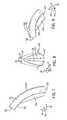
- FIG. 7is a side view of an embodiment of an insert that may be used in the packer assembly of FIG. 2 ;
- FIG. 8is a front view of the insert of FIG. 7 ;
- FIG. 9is a perspective view of the insert of FIG. 7 ;
- FIG. 10is a perspective view of the packer assembly of FIG. 2 with one insert removed;
- FIG. 11is a side view of an embodiment of a packer assembly having a collapsible ring insert.
- FIG. 12is a perspective view of the collapsible ring insert of FIG. 11 .
- Annular BOPsmay include a packer assembly (e.g., an annular packer assembly) disposed within a housing (e.g., an annular housing).
- a pistone.g., annular piston
- the packer assemblyincludes a packer (e.g., annular packer) and inserts (e.g., rigid inserts) coupled to the packer.
- the insertsmay be arranged in a configuration that facilitates an “iris-style closing” similar to that of an iris shutter of a camera.
- the packer assemblymay include a collapsible ring insert (e.g., annular insert) positioned proximate to a bottom axially-facing surface of the packer.
- the disclosed embodimentsmay facilitate stripping operations (e.g., operations in which a drill string moves through the central bore while the annular BOP is in the closed position or a partially closed position) and/or may reduce extrusion of the packer as the annular BOP moves from the open position to the closed position, thereby reducing wear on components of the annular BOP, for example.
- FIG. 1is a block diagram of an embodiment of mineral extraction system 10 .
- the illustrated mineral extraction system 10may be configured to extract various minerals and natural resources, including hydrocarbons (e.g., oil and/or natural gas), from the earth, or to inject substances into the earth.
- the mineral extraction system 10may be a land-based system (e.g., a surface system) or an offshore system (e.g., an offshore platform system).
- a BOP assembly 16e.g., BOP stack
- a wellhead 18which is coupled to a mineral deposit via a wellbore 26 .
- the wellhead 18may include any of a variety of other components such as a spool, a hanger, and a “Christmas” tree.
- the wellhead 18may return drilling fluid or mud to the surface 12 during drilling operations, for example. Downhole operations are carried out by a tubular string 24 (e.g., drill string, production tubing string, or the like) that extends, through the BOP assembly 16 , through the wellhead 18 , and into the wellbore 26 .
- a tubular string 24e.g., drill string, production tubing string, or the like
- the BOP assembly 16may include one or more annular BOPs 42 and/or one or more ram BOPs (e.g., shear ram, blind ram, blind shear ram, pipe ram, etc.).
- a central bore 44(e.g., flow bore) extends through the one or more annular BOPs 42 .
- each of the annular BOPs 42includes a packer assembly (e.g., annular packer assembly) that is configured to be mechanically squeezed radially inwardly to seal about the tubular string 24 extending through the central bore 44 (e.g., to block an annulus about the tubular string 24 ) and/or to block flow through the central bore 44 .
- the disclosed embodimentsinclude annular BOPs 42 with a packer assembly having various features, such as inserts coupled to a packer in a configuration that facilitates “iris-style closing” and/or a collapsible ring insert that supports the packer.
- FIG. 2is a cross-sectional side view of the annular BOP 42 that may be used in the system 10 of FIG. 1 .
- the annular BOP 42 and the components thereinare in an open position 50 .
- fluidmay flow through the central bore 44 of the annular BOP 42 .
- the annular BOP 42includes a housing 54 (e.g., annular housing) having a body 56 and a top 58 (e.g., top portion or top component) coupled to the body 56 .
- a piston 60e.g., annular piston
- a packer assembly 52e.g., annular packer assembly
- the packer assembly 52includes a packer 62 (e.g., an annular packer) and multiple inserts 64 (e.g., supporting or reinforcing inserts) positioned circumferentially about the packer 62 .
- the packer 62is a flexible component (e.g., elastomer) and the inserts 64 are rigid (e.g., metal or metal alloy).
- An adapter 66e.g., annular adapter is positioned between the body 56 and the top 58 .
- seals 65may be provided in the body 56 , the piston 60 , and/or the adapter 66 to seal chambers 67 , 69 (e.g., annular chambers) from the central bore 44 and from one another.
- the piston 60is configured to move relative to the housing 54 in the axial direction 30 .
- a fluide.g., a liquid and/or gas
- a first fluid conduit 68may be provided to the gap 69 via a first fluid conduit 68 to drive the piston 60 upwardly in the axial direction 30 , as shown by arrow 70 .
- the piston 60drives the packer 62 upwardly.
- an axially-facing surface 72e.g., e.g., packer-contacting surface, top surface, upper surface, or annular surface
- an axially-facing surface 74e.g., piston-contacting surface, bottom surface, lower surface, or annular surface
- the packer 62may move upwardly and inwardly within the top 58 to a closed position in which the packer 62 seals around the tubular string 24 extending through the central bore 44 and/or blocks fluid through the central bore 44 .
- a second fluid conduit 75is configured to provide a fluid (e.g., a liquid and/or gas) to the gap 67 to drive the piston 60 downwardly, thereby causing the packer 62 to move into the open position 50 .
- the packer assembly 52includes the packer 62 and the multiple inserts 64 .
- the multiple inserts 64may support the packer 62 and may facilitate an “iris-style closing” to enable the packer assembly 62 to move upwardly and inwardly within the top 58 to adjust the annular BOP 42 from the open position 50 the closed position.
- the multiple inserts 64are coupled to the packer 62 , are positioned circumferentially about the packer 62 (e.g., at discrete locations circumferentially about the packer 62 ), contact a radially-inner surface 78 (e.g., curved annular surface) of the top 58 , and are in an expanded position 77 while the annular BOP 42 is in the open position 50 .
- respective end portions 80e.g., radially-inner and/or upper end portions or tips
- first distance 79e.g., along the circumferential axis 34
- opposed respective end portions 80 of opposed inserts 64e.g., diametrically opposed on opposite sides of the central bore 44
- first diameter 81e.g., along the radial axis 32
- the distance between respective end portions 80 of adjacent inserts 64 and the distance between respective end portions 80 of opposed inserts 64may decrease as the annular BOP 42 moves from the open position 50 to the closed position.
- the multiple inserts 64do not directly contact the piston 60 while the annular BOP 42 is in the open position 50 .
- the packer 62is positioned between the multiple inserts 64 and the piston 60 along the axial axis 30 , and the multiple inserts 64 are separated from the axially-facing surface 74 of the packer 62 and/or the axially-facing surface 72 of the piston 60 by an axial distance 82 .
- the axial distance 82may be equal to or greater than approximately 10, 20, 30, 40, or 50 percent of a total height 83 (e.g., along the axial axis) of the packer assembly 52 .
- the multiple inserts 64do not directly contact the piston 60 while the annular BOP 42 is in the open position 50 , the closed position, or any position therebetween. However, in some embodiments, the multiple inserts 156 and the piston 60 may contact one another while the annular BOP 42 is in the open position 50 , the closed position, and/or a position therebetween.
- FIG. 3is a perspective partially cut-away view of an embodiment of the annular BOP 42 .
- the packer 62is transparent to illustrate the tubular member 24 and the central bore 44 .
- the annular BOP 42 and the components thereinare in a closed position 90 in which the packer 62 seals about the tubular member 24 and/or blocks fluid flow through the central bore 44 .
- the multiple inserts 64are in a compressed position 92 in which respective end portions 80 of adjacent inserts 64 are separated by a second distance 94 (e.g., along the circumferential axis 34 ) that is less than the first distance 79 discussed above with respect to FIG. 2 , and in which opposed respective end portions 80 of opposed inserts 64 define a second diameter 96 that is less than the first diameter 81 discussed above with respect to FIG. 2 .
- a second distance 94e.g., along the circumferential axis 34
- the piston 60drives the packer assembly 52 upwardly, and the packer 62 is compressed between the top 58 and the piston 60 and the multiple inserts 64 rotate radially-inwardly (e.g., move along a spiral or parabolic path toward the center of the bore 44 ) in a manner similar to that of an iris shutter of a camera.
- a radially-outer surface 105(e.g., curved annular surface) of each insert 64 may slide along the radially-inner surface 78 of the top 58 , and each insert 64 may be directed radially-inwardly due to the curvature of the radially-inner surface 78 of the top 58 .
- a first surface 98 (e.g., side surface) of one insert 64may move toward a second surface 100 (e.g., side surface) of an adjacent insert 64 , as shown by arrow 102 (e.g., the first distance 79 between respective end portions 80 of adjacent inserts 64 decreases), and/or the first surface 98 may slide along the second surface 100 , as shown by arrow 103 , to enable the annular BOP 42 to move from the open position 50 to the closed position 90 .
- the multiple inserts 64do not directly contact the piston 60 while the annular BOP 42 is in the closed position 90 .
- the packer 62is positioned between the multiple inserts 64 and the piston 60 along the axial axis 30 .
- the configuration of the multiple inserts 64may reduce extrusion of the flexible material of the packer 62 as the packer assembly 52 moves from the open position 50 to the closed position 90 , for example.
- the configuration of the multiple inserts 64may also facilitate stripping operations in which the tubular member 24 moves axially through the central bore 44 of the annular BOP 42 , while the annular BOP 42 is in the closed position 90 or a partially closed position.
- the tubular member 24may include joints 104 (e.g., radially-expanded portions or connections between pipe sections that form the tubular member 24 ).
- the joints 104may contact and exert a force on the respective end portions 80 of the multiple inserts 64 .
- the packer 62i.e., a flexible or elastomeric component
- the packer 62may dampen the force, such that a relatively low percentage of the force is transferred to the piston 60 (e.g., as compared to some typical annular BOPs 42 ).
- the multiple inserts 64may rotate radially-outwardly and/or slide relative to one another to accommodate the joint 104 , thereby reducing the force transferred to the piston 60 and/or reducing wear on various components of the annular BOP 42 and/or the tubular member 24 , for example.
- FIG. 4is a side view of an embodiment of the packer assembly 52 in the open position 50
- FIG. 5is a perspective top view of an embodiment of the packer assembly 52 in the open position 50
- FIG. 6is a top view of the packer assembly 52 in the open position 50 .
- the multiple inserts 64are positioned circumferentially about the packer 62 .
- Each insertincludes the radially-outer surface 105 , which curves radially-inwardly along the axial axis 30 .
- each insert 64is flush (e.g., do not extend radially-outwardly from) with a radially-outer surface 107 (e.g., annular surface or top-contacting surface) of the packer 62 while the annular BOP 42 is in the open position 50 , and the radially-outer surface 105 curves radially-inwardly along the axial axis 30 , such that the respective end portion 80 of each insert 64 is located radially-inwardly from the radially-outer surface 107 of the packer 62 .
- a radially-outer surface 107e.g., annular surface or top-contacting surface
- Each insert 64is oriented at an angle relative to the axial axis 30 and relative to the central bore 44 of the packer assembly 52 , while the packer assembly 52 is in the open position 50 .
- a central axis 110e.g., longitudinal axis
- each insert 64is positioned at an angle 112 (e.g., non-parallel) relative to the axial axis 30 and relative to the central bore 44 of the packer assembly 52 .
- the angle 112may change (e.g., increase) as the packer assembly 52 moves from the open position 50 to the closed position 90 .
- respective end portions 80 of adjacent inserts 64are separated by the first distance 79
- opposed respective end portions 80 of opposed inserts 64are separated by the first diameter 81 .
- the distance and the diameterdecrease as the packer assembly 52 moves from the open position 50 to the closed position 90 .
- the multiple inserts 64move in an “iris-style closing” manner in which each insert 64 rotates radially-inwardly along a generally a spiral or parabolic path as the packer assembly 52 moves from the open position 50 to the closed position 90 .
- the first surface 98 of one insert 64may move toward and/or slide along the second surface 100 of the adjacent insert 64 , as shown by arrows 102 and 103 , as the packer assembly 52 moves from the open position 50 to the closed position 90 .
- FIG. 7is a side view of an embodiment of one insert 64 that may be used in the packer assembly 52
- FIG. 8is a front view of one insert 64 that may be used in the packer assembly 52
- FIG. 9is a perspective view of one insert 64 that may be used in the packer assembly 52 .
- the insert 64includes the radially-outer surface 105 that curves and extends between the end portion 80 and another end portion 122 .
- the curved radially-outer surface 105may have a curvature that generally corresponds to the curvature of the radially-inner surface 78 of the top 58 , as shown in FIGS. 2 and 3 , for example.
- a widthmay vary between the end portion 80 and the another end portion 122 .
- a first width 124 proximate to the end portion 80is less than a second width 126 proximate to the another end portion 122 .
- the insert 64includes a protrusion 128 (e.g., ridge, extension, packer-engaging protrusion) that extends radially-inwardly from a radially-inner surface 30 (e.g., curved surface) of the insert 64 .
- the protrusion 128may engage a corresponding recess of the packer 62 , thereby securing the insert 64 to the packer 68 .
- FIG. 10is a perspective view of the packer assembly 52 with one insert 64 removed and showing a recess 140 (e.g., cavity or seat) and a groove 142 formed in the packer 62 .
- the recess 140has a shape that generally corresponds to the insert 64 and the groove 142 has a shape that generally corresponds to the protrusion 128 extending from the radially-inner surface 30 of the insert 64 .
- the multiple inserts 64may be coupled to and may move with the packer 62 within the housing 54 of the annular BOP 42 .
- the packer assembly 52may be manufactured via any suitable technique, although in certain embodiments, the inserts 64 may be secured to a mold housing (e.g., via respective fasteners, which may be received by threaded openings 146 ), and the material that forms the packer 62 may then be deposited into the mold housing about the inserts 64 , thereby forming the packer 62 having the recess 140 and the grooves 142 and coupling the packer 62 to the inserts 64 .
- FIG. 11is a side view of an embodiment of a packer assembly 150 (e.g., annular packer assembly) having a collapsible ring insert 152 (e.g., annular insert) that may be utilized within the annular BOP 42 of FIG. 2 .
- the packer assembly 150may include a packer 154 (e.g., annular packer) and multiple inserts 156 .
- the packer 154may include any of the features of the packer 60 discussed above with respect to FIGS. 2-10 , and may also be configured to receive and/or couple to the collapsible ring insert 152 .
- the multiple inserts 156may include any of the features of the multiple inserts 64 discussed above with respect to FIGS. 2-10 .
- the multiple inserts 156are positioned circumferentially about a first axial end 155 (e.g., upper or top end portion) of the packer 62 , and the collapsible ring insert 152 extends circumferentially about a second axial end 157 (e.g., lower or bottom end portion) of the packer 62 .
- the packer 62is positioned between the multiple inserts 156 and the collapsible ring insert 152 along the axial axis 30 , and the multiple inserts 156 are separated from the collapsible ring insert 152 by an axial distance 159 .
- the multiple inserts 156 and the collapsible ring insert 152do not contact one another while the annular BOP 42 is in the open position 50 , and may not contact one another while the annular BOP 42 is in the closed position or any position therebetween. However, in some embodiments, the multiple inserts 156 and the collapsible ring insert 152 may contact one another while the annular BOP 42 is in the open position 50 , the closed position, and/or a position therebetween.
- the piston 60may contact an axially-facing surface 158 of the packer 154 and/or an axially-facing surface 160 of the collapsible ring insert 152 as the piston 60 drives the packer assembly 150 within the housing 54 of the annular BOP of FIG. 2 .
- the collapsible ring insert 152may support the packer 154 and/or reduce extrusion of the packer 154 as the annular BOP 42 moves from the open position 50 to the closed position 90 , for example.
- FIG. 12is a perspective view of the collapsible ring insert 152 of FIG. 11 .
- the collapsible ring insert 152includes multiple segments 162 arranged into a ring or annular structure, and the multiple segments 162 are configured to move relative to one another to enable the collapsible ring insert 152 to move from the illustrated expanded position 164 to a collapsed position as the annular BOP 42 moves from the open position 50 to the closed position 90 .
- An inner diameter 166 defined by the collapsible ring insert 152may decrease as the collapsible ring insert 152 transitions from the expanded position 164 to the collapsed position.
- Each segment 162 of the collapsible ring insert 152may include a key portion 168 (e.g., first portion or radially-inner portion) and a slot portion 170 (e.g., second portion, radially-outer portion, or seat portion).
- Each key portion 168may be received by a respective slot portion 170 of an adjacent segment 162 , as shown by arrows 172 , thereby moving respective key portions 168 of adjacent segments 162 toward one another, moving respective slot portions 170 of adjacent segments 162 toward one another, and enabling transition from the expanded position 164 to the collapsed position.
- the respective slot portions 170 of adjacent segments 162are separated from one another by a gap 174 (e.g., circumferential gap) while the collapsible ring insert 152 is in the expanded position 164 , and a circumferential distance 176 across the gap 174 may decrease as the collapsible ring insert 152 moves from the expanded position 164 to the collapsed position.
- a gap 174e.g., circumferential gap
- the respective key portions 168 of adjacent segments 162are separated from one another by a gap 178 (e.g., circumferential gap) while the collapsible ring insert 152 is in the expanded position 164 , and a circumferential distance 180 across the gap 178 decreases as the collapsible ring insert 152 moves from the expanded position 164 to the collapsed position.
- a gap 178e.g., circumferential gap
- the packer 62may be positioned within or fill the gap 174 .
- the packer 62may be positioned within or fill the gap 178 .
- the packer 62 within the gap 174 and/or the gap 178may be compressed as the collapsible ring insert 152 moves from the expanded position 164 to the collapsed position, the packer 62 may limit the movement of the collapsible ring insert 152 toward the collapsed position, and/or the packer 62 may bias the collapsible ring insert 152 toward the expanded position 164 .
- the packer assembly 150may be manufactured via any suitable technique.
- the collapsible ring insert 152 and the multiple inserts 156may be secured to a mold housing (e.g., via respective threaded fasteners), and the material that forms the packer 154 may then be deposited into the mold housing about the collapsible ring insert 152 and the multiple inserts 156 .
- the packer 154may entirely surround the collapsible ring insert 152 or may surround a portion of the collapsible ring insert 152 , while leaving the axially-facing surface 160 and/or a radially-outer surface 182 of the respective slot portions 170 exposed, uncovered, or visible (e.g., only the axially-facing surface 160 and/or the radially-outer surface 182 of the respective slot portions 170 are exposed, uncovered, or visible).
- collapsible ring insert 152 illustrated in FIGS. 11 and 12may be utilized in combination with any of the features described or illustrated with respect to FIGS. 1-10 .
Landscapes
- Engineering & Computer Science (AREA)
- Life Sciences & Earth Sciences (AREA)
- Geology (AREA)
- Mining & Mineral Resources (AREA)
- Physics & Mathematics (AREA)
- Environmental & Geological Engineering (AREA)
- Fluid Mechanics (AREA)
- General Life Sciences & Earth Sciences (AREA)
- Geochemistry & Mineralogy (AREA)
- General Engineering & Computer Science (AREA)
- Reciprocating Pumps (AREA)
- Mechanical Engineering (AREA)
Abstract
Description
Claims (16)
Priority Applications (1)
| Application Number | Priority Date | Filing Date | Title |
|---|---|---|---|
| US15/599,886US10590728B2 (en) | 2017-05-19 | 2017-05-19 | Annular blowout preventer packer assembly |
Applications Claiming Priority (1)
| Application Number | Priority Date | Filing Date | Title |
|---|---|---|---|
| US15/599,886US10590728B2 (en) | 2017-05-19 | 2017-05-19 | Annular blowout preventer packer assembly |
Publications (2)
| Publication Number | Publication Date |
|---|---|
| US20180334876A1 US20180334876A1 (en) | 2018-11-22 |
| US10590728B2true US10590728B2 (en) | 2020-03-17 |
Family
ID=64269998
Family Applications (1)
| Application Number | Title | Priority Date | Filing Date |
|---|---|---|---|
| US15/599,886ActiveUS10590728B2 (en) | 2017-05-19 | 2017-05-19 | Annular blowout preventer packer assembly |
Country Status (1)
| Country | Link |
|---|---|
| US (1) | US10590728B2 (en) |
Cited By (1)
| Publication number | Priority date | Publication date | Assignee | Title |
|---|---|---|---|---|
| US11414950B2 (en)* | 2018-05-22 | 2022-08-16 | Kinetic Pressure Control Ltd. | Iris valve type well annular pressure control device and method |
Families Citing this family (8)
| Publication number | Priority date | Publication date | Assignee | Title |
|---|---|---|---|---|
| GB2555231B (en)* | 2015-05-29 | 2021-05-05 | Halliburton Energy Services Inc | Packing element back-up system incorporating iris mechanism |
| US10724324B2 (en)* | 2017-09-19 | 2020-07-28 | Cameron International Corporation | Operating system cartridge for an annular blowout preventer |
| CA3191851A1 (en) | 2020-08-25 | 2022-03-03 | Schlumberger Canada Limited | Annular blowout preventer |
| US11174698B1 (en) | 2020-12-18 | 2021-11-16 | Halliburton Energy Services, Inc. | Rotating control device element reinforcement petals |
| WO2024086052A1 (en)* | 2022-10-20 | 2024-04-25 | Schlumberger Technology Corporation | Electric annular with internal motor |
| WO2024196854A1 (en)* | 2023-03-21 | 2024-09-26 | Schlumberger Technology Corporation | Rotating control device with damper assembly |
| US12152458B1 (en)* | 2023-10-03 | 2024-11-26 | Schlumberger Technology Corporation | Packer assembly for blowout preventer |
| US12359524B2 (en)* | 2023-12-15 | 2025-07-15 | Schlumberger Technology Corporation | Oilfield seal tool |
Citations (57)
| Publication number | Priority date | Publication date | Assignee | Title |
|---|---|---|---|---|
| US2038140A (en) | 1931-07-06 | 1936-04-21 | Hydril Co | Packing head |
| US2287205A (en) | 1939-01-27 | 1942-06-23 | Hydril Company Of California | Packing head |
| US2609836A (en) | 1946-08-16 | 1952-09-09 | Hydril Corp | Control head and blow-out preventer |
| US2812197A (en) | 1955-08-16 | 1957-11-05 | Shaffer Tool Works | Toggle packer, well head preventer |
| US2832617A (en) | 1954-05-13 | 1958-04-29 | Shaffer Tool Works | Stationary, well head preventer |
| US3323773A (en) | 1963-02-01 | 1967-06-06 | Shaffer Tool Works | Blow-out preventer |
| US3486759A (en)* | 1967-08-25 | 1969-12-30 | Hydril Co | Sealing of underwater equipment |
| US3561723A (en)* | 1968-05-07 | 1971-02-09 | Edward T Cugini | Stripping and blow-out preventer device |
| US3737139A (en) | 1971-06-28 | 1973-06-05 | Hydril Co | Annular blowout preventer |
| US3887158A (en)* | 1971-05-17 | 1975-06-03 | Otis Eng Co | Blow out preventers |
| US3897071A (en) | 1972-04-27 | 1975-07-29 | Hydril Co | Annular blowout preventer with variable inside diameter |
| US3915426A (en) | 1973-01-26 | 1975-10-28 | Hydril Co | Blowout preventer with variable inside diameter |
| US3994472A (en) | 1975-01-17 | 1976-11-30 | Cameron Iron Works, Inc. | Annular type blowout preventer |
| US4095805A (en)* | 1976-10-15 | 1978-06-20 | Cameron Iron Works, Inc. | Annular blowout preventer |
| US4099699A (en) | 1976-09-10 | 1978-07-11 | Cameron Iron Works, Inc. | Annular blowout preventer |
| US4283039A (en) | 1980-06-05 | 1981-08-11 | Nl Industries, Inc. | Annular blowout preventer with upper and lower spherical sealing surfaces |
| US4310139A (en) | 1980-04-04 | 1982-01-12 | Cameron Iron Works, Inc. | Annular blowout preventer |
| US4381868A (en) | 1981-07-24 | 1983-05-03 | Cameron Iron Works, Inc. | Pressure-actuated wellhead sealing assembly |
| US4458876A (en)* | 1982-09-16 | 1984-07-10 | Ventre Corporation | Annular blowout preventer |
| US4460151A (en) | 1981-12-29 | 1984-07-17 | Cameron Iron Works, Inc. | Annular blowout preventer |
| US4460150A (en) | 1981-12-28 | 1984-07-17 | Cameron Iron Works, Inc. | Annular blowout preventer |
| US4508311A (en) | 1982-11-12 | 1985-04-02 | Cameron Iron Works, Inc. | Annular blowout preventer |
| US4541490A (en)* | 1983-09-06 | 1985-09-17 | Joy Manufacture Company | Adapter for a wellhead |
| US4579314A (en) | 1983-04-13 | 1986-04-01 | Cameron Iron Works, Inc. | Annular blowout preventer |
| US4602794A (en) | 1980-06-05 | 1986-07-29 | Nl Industries, Inc. | Annular blowout preventer with upper and lower spherical sealing surfaces and rigid translation element |
| US4605195A (en) | 1985-05-01 | 1986-08-12 | Hydril Company | Annular blowout preventer packing unit |
| US4858882A (en)* | 1987-05-27 | 1989-08-22 | Beard Joseph O | Blowout preventer with radial force limiter |
| US4949785A (en) | 1989-05-02 | 1990-08-21 | Beard Joseph O | Force-limiting/wear compensating annular sealing element for blowout preventers |
| US5116017A (en) | 1990-10-18 | 1992-05-26 | Granger Stanley W | Annular sealing element with self-pivoting inserts for blowout preventers |
| US5224557A (en) | 1991-07-22 | 1993-07-06 | Folsom Metal Products, Inc. | Rotary blowout preventer adaptable for use with both kelly and overhead drive mechanisms |
| US5361832A (en) | 1993-06-17 | 1994-11-08 | Drexel Oilfield Services, Inc. | Annular packer and insert |
| US6367804B1 (en) | 2000-04-14 | 2002-04-09 | Cooper Cameron Corporation | Variable bore ram packer for tapered tubular members in a ram type blowout preventer |
| US20040164494A1 (en) | 2003-02-20 | 2004-08-26 | Raul Araujo | BOP assembly with metal inserts |
| US6955357B2 (en) | 2002-10-07 | 2005-10-18 | Cooper Cameron Corporation | Extended range variable bore ram packer for a ram type blowout preventer |
| US7159669B2 (en)* | 1999-03-02 | 2007-01-09 | Weatherford/Lamb, Inc. | Internal riser rotating control head |
| US7240727B2 (en)* | 2004-02-20 | 2007-07-10 | Williams John R | Armored stripper rubber |
| US20080023917A1 (en) | 2006-07-28 | 2008-01-31 | Hydril Company Lp | Seal for blowout preventer with selective debonding |
| US20090321066A1 (en) | 2005-06-20 | 2009-12-31 | Hydril Usa Manufacturing Llc | Packer Insert for Sealing on Multiple Items Used in a Wellbore |
| US20100294482A1 (en) | 2008-02-01 | 2010-11-25 | Cameron International Corporation | Variable Bore Packer for a Blowout Preventer |
| WO2011128690A1 (en) | 2010-04-13 | 2011-10-20 | Managed Pressure Operations Pte. Limited | Blowout preventer assembly |
| US8176933B2 (en) | 2006-07-28 | 2012-05-15 | Hydril Usa Manufacturing Llc | Annular BOP packing unit |
| US8215613B2 (en)* | 2008-06-06 | 2012-07-10 | Neil Cheung | Virtual variable valve intake and exhaust for the internal combustion engine |
| US20120227987A1 (en) | 2011-03-09 | 2012-09-13 | National Oilwell Varco, L.P. | Method and apparatus for sealing a wellbore |
| WO2013116234A2 (en) | 2012-02-03 | 2013-08-08 | National Oilwell Varco, L.P. | Blowout preventer and method of using same |
| US8555980B1 (en)* | 2010-06-09 | 2013-10-15 | John Powell | Oil well blowout containment device |
| US20140014361A1 (en)* | 2012-07-13 | 2014-01-16 | Clinton D. Nelson | Automatic Annular Blow-Out Preventer |
| US20140183381A1 (en) | 2012-12-31 | 2014-07-03 | Hydril Usa Manufacturing Llc | Reinforced variable ram packer using fabric |
| US20140209316A1 (en) | 2013-01-30 | 2014-07-31 | Rowan Deepwater Drilling (Gibraltar) Ltd. | Riser fluid handling system |
| WO2015028790A2 (en) | 2013-08-27 | 2015-03-05 | Enovate Systems Limited | Improved annular blow out preventer |
| US9068433B2 (en) | 2013-03-15 | 2015-06-30 | Cameron International Corporation | Diverter stabbing dog |
| US20150275609A1 (en)* | 2014-03-28 | 2015-10-01 | National Oilwell Varco, L.P. | Spherical blowout preventer with energizeable packer seal and method of using same |
| US20160201422A1 (en) | 2015-01-13 | 2016-07-14 | Chevron U.S.A. Inc. | Annular Blowout Preventer (BOP) Packing Unit with Integrated Secondary Sealing Compound |
| US20160230492A1 (en) | 2013-03-15 | 2016-08-11 | Cameron International Corporation | Riser gas handling system |
| US20170130575A1 (en) | 2015-11-05 | 2017-05-11 | Cameron International Corporation | Smart seal methods and systems |
| US20170145770A1 (en)* | 2015-11-24 | 2017-05-25 | Freudenberg Oil & Gas, Llc | Spherical blow out preventer annular seal |
| US20180023361A1 (en) | 2016-07-25 | 2018-01-25 | Cameron International Corporation | Packer Assembly with Multi-Material Inserts for Blowout Preventer |
| US20180258728A1 (en) | 2017-03-13 | 2018-09-13 | Cameron International Corporation | Packer for annular blowout preventer |
- 2017
- 2017-05-19USUS15/599,886patent/US10590728B2/enactiveActive
Patent Citations (60)
| Publication number | Priority date | Publication date | Assignee | Title |
|---|---|---|---|---|
| US2038140A (en) | 1931-07-06 | 1936-04-21 | Hydril Co | Packing head |
| US2287205A (en) | 1939-01-27 | 1942-06-23 | Hydril Company Of California | Packing head |
| US2609836A (en) | 1946-08-16 | 1952-09-09 | Hydril Corp | Control head and blow-out preventer |
| US2832617A (en) | 1954-05-13 | 1958-04-29 | Shaffer Tool Works | Stationary, well head preventer |
| US2812197A (en) | 1955-08-16 | 1957-11-05 | Shaffer Tool Works | Toggle packer, well head preventer |
| US3323773A (en) | 1963-02-01 | 1967-06-06 | Shaffer Tool Works | Blow-out preventer |
| US3486759A (en)* | 1967-08-25 | 1969-12-30 | Hydril Co | Sealing of underwater equipment |
| US3561723A (en)* | 1968-05-07 | 1971-02-09 | Edward T Cugini | Stripping and blow-out preventer device |
| US3887158A (en)* | 1971-05-17 | 1975-06-03 | Otis Eng Co | Blow out preventers |
| US3737139A (en) | 1971-06-28 | 1973-06-05 | Hydril Co | Annular blowout preventer |
| US3897071A (en) | 1972-04-27 | 1975-07-29 | Hydril Co | Annular blowout preventer with variable inside diameter |
| US3915426A (en) | 1973-01-26 | 1975-10-28 | Hydril Co | Blowout preventer with variable inside diameter |
| US3994472A (en) | 1975-01-17 | 1976-11-30 | Cameron Iron Works, Inc. | Annular type blowout preventer |
| US4099699A (en) | 1976-09-10 | 1978-07-11 | Cameron Iron Works, Inc. | Annular blowout preventer |
| US4095805A (en)* | 1976-10-15 | 1978-06-20 | Cameron Iron Works, Inc. | Annular blowout preventer |
| US4310139A (en) | 1980-04-04 | 1982-01-12 | Cameron Iron Works, Inc. | Annular blowout preventer |
| US4602794A (en) | 1980-06-05 | 1986-07-29 | Nl Industries, Inc. | Annular blowout preventer with upper and lower spherical sealing surfaces and rigid translation element |
| US4283039A (en) | 1980-06-05 | 1981-08-11 | Nl Industries, Inc. | Annular blowout preventer with upper and lower spherical sealing surfaces |
| US4381868A (en) | 1981-07-24 | 1983-05-03 | Cameron Iron Works, Inc. | Pressure-actuated wellhead sealing assembly |
| US4460150A (en) | 1981-12-28 | 1984-07-17 | Cameron Iron Works, Inc. | Annular blowout preventer |
| US4460151A (en) | 1981-12-29 | 1984-07-17 | Cameron Iron Works, Inc. | Annular blowout preventer |
| US4458876A (en)* | 1982-09-16 | 1984-07-10 | Ventre Corporation | Annular blowout preventer |
| US4508311A (en) | 1982-11-12 | 1985-04-02 | Cameron Iron Works, Inc. | Annular blowout preventer |
| US4579314A (en) | 1983-04-13 | 1986-04-01 | Cameron Iron Works, Inc. | Annular blowout preventer |
| US4541490A (en)* | 1983-09-06 | 1985-09-17 | Joy Manufacture Company | Adapter for a wellhead |
| US4605195A (en) | 1985-05-01 | 1986-08-12 | Hydril Company | Annular blowout preventer packing unit |
| US4858882A (en)* | 1987-05-27 | 1989-08-22 | Beard Joseph O | Blowout preventer with radial force limiter |
| US4949785A (en) | 1989-05-02 | 1990-08-21 | Beard Joseph O | Force-limiting/wear compensating annular sealing element for blowout preventers |
| US5116017A (en) | 1990-10-18 | 1992-05-26 | Granger Stanley W | Annular sealing element with self-pivoting inserts for blowout preventers |
| US5224557A (en) | 1991-07-22 | 1993-07-06 | Folsom Metal Products, Inc. | Rotary blowout preventer adaptable for use with both kelly and overhead drive mechanisms |
| US5361832A (en) | 1993-06-17 | 1994-11-08 | Drexel Oilfield Services, Inc. | Annular packer and insert |
| US7159669B2 (en)* | 1999-03-02 | 2007-01-09 | Weatherford/Lamb, Inc. | Internal riser rotating control head |
| US6367804B1 (en) | 2000-04-14 | 2002-04-09 | Cooper Cameron Corporation | Variable bore ram packer for tapered tubular members in a ram type blowout preventer |
| US6955357B2 (en) | 2002-10-07 | 2005-10-18 | Cooper Cameron Corporation | Extended range variable bore ram packer for a ram type blowout preventer |
| US20040164494A1 (en) | 2003-02-20 | 2004-08-26 | Raul Araujo | BOP assembly with metal inserts |
| US7240727B2 (en)* | 2004-02-20 | 2007-07-10 | Williams John R | Armored stripper rubber |
| US20090321066A1 (en) | 2005-06-20 | 2009-12-31 | Hydril Usa Manufacturing Llc | Packer Insert for Sealing on Multiple Items Used in a Wellbore |
| US8176933B2 (en) | 2006-07-28 | 2012-05-15 | Hydril Usa Manufacturing Llc | Annular BOP packing unit |
| US20080023917A1 (en) | 2006-07-28 | 2008-01-31 | Hydril Company Lp | Seal for blowout preventer with selective debonding |
| US8727303B2 (en) | 2008-02-01 | 2014-05-20 | Cameron International Corporation | Variable bore packer for a blowout preventer |
| US20100294482A1 (en) | 2008-02-01 | 2010-11-25 | Cameron International Corporation | Variable Bore Packer for a Blowout Preventer |
| US8215613B2 (en)* | 2008-06-06 | 2012-07-10 | Neil Cheung | Virtual variable valve intake and exhaust for the internal combustion engine |
| WO2011128690A1 (en) | 2010-04-13 | 2011-10-20 | Managed Pressure Operations Pte. Limited | Blowout preventer assembly |
| US8555980B1 (en)* | 2010-06-09 | 2013-10-15 | John Powell | Oil well blowout containment device |
| US20120227987A1 (en) | 2011-03-09 | 2012-09-13 | National Oilwell Varco, L.P. | Method and apparatus for sealing a wellbore |
| WO2013116234A2 (en) | 2012-02-03 | 2013-08-08 | National Oilwell Varco, L.P. | Blowout preventer and method of using same |
| US20140014361A1 (en)* | 2012-07-13 | 2014-01-16 | Clinton D. Nelson | Automatic Annular Blow-Out Preventer |
| US20140183381A1 (en) | 2012-12-31 | 2014-07-03 | Hydril Usa Manufacturing Llc | Reinforced variable ram packer using fabric |
| US20140209316A1 (en) | 2013-01-30 | 2014-07-31 | Rowan Deepwater Drilling (Gibraltar) Ltd. | Riser fluid handling system |
| US20160230492A1 (en) | 2013-03-15 | 2016-08-11 | Cameron International Corporation | Riser gas handling system |
| US9068433B2 (en) | 2013-03-15 | 2015-06-30 | Cameron International Corporation | Diverter stabbing dog |
| US9765587B2 (en) | 2013-03-15 | 2017-09-19 | Cameron International Corporation | Riser gas handling system |
| WO2015028790A2 (en) | 2013-08-27 | 2015-03-05 | Enovate Systems Limited | Improved annular blow out preventer |
| US20150275609A1 (en)* | 2014-03-28 | 2015-10-01 | National Oilwell Varco, L.P. | Spherical blowout preventer with energizeable packer seal and method of using same |
| US9580987B2 (en)* | 2014-03-28 | 2017-02-28 | National Oilwell Varco, L.P. | Spherical blowout preventer with energizeable packer seal and method of using same |
| US20160201422A1 (en) | 2015-01-13 | 2016-07-14 | Chevron U.S.A. Inc. | Annular Blowout Preventer (BOP) Packing Unit with Integrated Secondary Sealing Compound |
| US20170130575A1 (en) | 2015-11-05 | 2017-05-11 | Cameron International Corporation | Smart seal methods and systems |
| US20170145770A1 (en)* | 2015-11-24 | 2017-05-25 | Freudenberg Oil & Gas, Llc | Spherical blow out preventer annular seal |
| US20180023361A1 (en) | 2016-07-25 | 2018-01-25 | Cameron International Corporation | Packer Assembly with Multi-Material Inserts for Blowout Preventer |
| US20180258728A1 (en) | 2017-03-13 | 2018-09-13 | Cameron International Corporation | Packer for annular blowout preventer |
Non-Patent Citations (4)
| Title |
|---|
| ‘embed’. Dictionary.com [online]. [retrieved on Sep. 12, 2018]. Retrieved from the Internet: <URL: https://www.dictionary.com/browse/embedded>. |
| Durometer Shore Hardness Scale. Smooth-On, Inc. [retrieved on Feb. 20, 2018]. Retrieved from the Internet: <URL: https://www.smooth-on.com/page/durometer-shore-hardness-scale/>. |
| 'embed'. Dictionary.com [online]. [retrieved on Sep. 12, 2018]. Retrieved from the Internet: <URL: https://www.dictionary.com/browse/embedded>. |
| Non final office action for the cross referenced U.S. Appl. No. 15/456,734 dated Dec. 29, 2017. |
Cited By (1)
| Publication number | Priority date | Publication date | Assignee | Title |
|---|---|---|---|---|
| US11414950B2 (en)* | 2018-05-22 | 2022-08-16 | Kinetic Pressure Control Ltd. | Iris valve type well annular pressure control device and method |
Also Published As
| Publication number | Publication date |
|---|---|
| US20180334876A1 (en) | 2018-11-22 |
Similar Documents
| Publication | Publication Date | Title |
|---|---|---|
| US10590728B2 (en) | Annular blowout preventer packer assembly | |
| EP2558676B1 (en) | Blowout preventer assembly | |
| US9869148B2 (en) | Wellsite connector with floating seal member and method of using same | |
| US9869150B2 (en) | Integrated wellhead assembly | |
| US10655430B2 (en) | Top-down squeeze system and method | |
| US11905783B2 (en) | Riser system | |
| US10513907B2 (en) | Top-down squeeze system and method | |
| US20210087900A1 (en) | Blowout preventer annular | |
| US12000230B2 (en) | Annular blowout preventer | |
| US9963951B2 (en) | Annular blowout preventer | |
| US10669803B2 (en) | Wellhead assembly with internal casing hanger pack-off |
Legal Events
| Date | Code | Title | Description |
|---|---|---|---|
| STPP | Information on status: patent application and granting procedure in general | Free format text:NON FINAL ACTION MAILED | |
| STPP | Information on status: patent application and granting procedure in general | Free format text:NOTICE OF ALLOWANCE MAILED -- APPLICATION RECEIVED IN OFFICE OF PUBLICATIONS | |
| STPP | Information on status: patent application and granting procedure in general | Free format text:DOCKETED NEW CASE - READY FOR EXAMINATION | |
| STPP | Information on status: patent application and granting procedure in general | Free format text:NOTICE OF ALLOWANCE MAILED -- APPLICATION RECEIVED IN OFFICE OF PUBLICATIONS | |
| AS | Assignment | Owner name:CAMERON INTERNATIONAL CORPORATION, TEXAS Free format text:ASSIGNMENT OF ASSIGNORS INTEREST;ASSIGNOR:ZONOZ, RAY;REEL/FRAME:051518/0496 Effective date:20191023 | |
| AS | Assignment | Owner name:CAMERON INTERNATIONAL CORPORATION, TEXAS Free format text:ASSIGNMENT OF ASSIGNORS INTEREST;ASSIGNOR:ARAUJO, RAUL;REEL/FRAME:051636/0505 Effective date:20200127 | |
| STPP | Information on status: patent application and granting procedure in general | Free format text:PUBLICATIONS -- ISSUE FEE PAYMENT VERIFIED | |
| STCF | Information on status: patent grant | Free format text:PATENTED CASE | |
| MAFP | Maintenance fee payment | Free format text:PAYMENT OF MAINTENANCE FEE, 4TH YEAR, LARGE ENTITY (ORIGINAL EVENT CODE: M1551); ENTITY STATUS OF PATENT OWNER: LARGE ENTITY Year of fee payment:4 |