US10589413B2 - Power tool with anti-kickback control system - Google Patents
Power tool with anti-kickback control systemDownload PDFInfo
- Publication number
- US10589413B2 US10589413B2US15/604,728US201715604728AUS10589413B2US 10589413 B2US10589413 B2US 10589413B2US 201715604728 AUS201715604728 AUS 201715604728AUS 10589413 B2US10589413 B2US 10589413B2
- Authority
- US
- United States
- Prior art keywords
- motor
- current
- mode
- rotational motion
- signal
- Prior art date
- Legal status (The legal status is an assumption and is not a legal conclusion. Google has not performed a legal analysis and makes no representation as to the accuracy of the status listed.)
- Active, expires
Links
Images


Classifications
- B—PERFORMING OPERATIONS; TRANSPORTING
- B25—HAND TOOLS; PORTABLE POWER-DRIVEN TOOLS; MANIPULATORS
- B25F—COMBINATION OR MULTI-PURPOSE TOOLS NOT OTHERWISE PROVIDED FOR; DETAILS OR COMPONENTS OF PORTABLE POWER-DRIVEN TOOLS NOT PARTICULARLY RELATED TO THE OPERATIONS PERFORMED AND NOT OTHERWISE PROVIDED FOR
- B25F5/00—Details or components of portable power-driven tools not particularly related to the operations performed and not otherwise provided for
- B25F5/02—Construction of casings, bodies or handles
- B—PERFORMING OPERATIONS; TRANSPORTING
- B25—HAND TOOLS; PORTABLE POWER-DRIVEN TOOLS; MANIPULATORS
- B25B—TOOLS OR BENCH DEVICES NOT OTHERWISE PROVIDED FOR, FOR FASTENING, CONNECTING, DISENGAGING OR HOLDING
- B25B21/00—Portable power-driven screw or nut setting or loosening tools; Attachments for drilling apparatus serving the same purpose
- B25B21/002—Portable power-driven screw or nut setting or loosening tools; Attachments for drilling apparatus serving the same purpose for special purposes
- B—PERFORMING OPERATIONS; TRANSPORTING
- B25—HAND TOOLS; PORTABLE POWER-DRIVEN TOOLS; MANIPULATORS
- B25B—TOOLS OR BENCH DEVICES NOT OTHERWISE PROVIDED FOR, FOR FASTENING, CONNECTING, DISENGAGING OR HOLDING
- B25B23/00—Details of, or accessories for, spanners, wrenches, screwdrivers
- B25B23/14—Arrangement of torque limiters or torque indicators in wrenches or screwdrivers
- B25B23/147—Arrangement of torque limiters or torque indicators in wrenches or screwdrivers specially adapted for electrically operated wrenches or screwdrivers
- B—PERFORMING OPERATIONS; TRANSPORTING
- B25—HAND TOOLS; PORTABLE POWER-DRIVEN TOOLS; MANIPULATORS
- B25F—COMBINATION OR MULTI-PURPOSE TOOLS NOT OTHERWISE PROVIDED FOR; DETAILS OR COMPONENTS OF PORTABLE POWER-DRIVEN TOOLS NOT PARTICULARLY RELATED TO THE OPERATIONS PERFORMED AND NOT OTHERWISE PROVIDED FOR
- B25F5/00—Details or components of portable power-driven tools not particularly related to the operations performed and not otherwise provided for
- F—MECHANICAL ENGINEERING; LIGHTING; HEATING; WEAPONS; BLASTING
- F16—ENGINEERING ELEMENTS AND UNITS; GENERAL MEASURES FOR PRODUCING AND MAINTAINING EFFECTIVE FUNCTIONING OF MACHINES OR INSTALLATIONS; THERMAL INSULATION IN GENERAL
- F16P—SAFETY DEVICES IN GENERAL; SAFETY DEVICES FOR PRESSES
- F16P3/00—Safety devices acting in conjunction with the control or operation of a machine; Control arrangements requiring the simultaneous use of two or more parts of the body
- F16P3/008—Devices for directly stopping or interrupting the drive or gear in case of danger to the machine, e.g. devices with clutches
- G—PHYSICS
- G01—MEASURING; TESTING
- G01C—MEASURING DISTANCES, LEVELS OR BEARINGS; SURVEYING; NAVIGATION; GYROSCOPIC INSTRUMENTS; PHOTOGRAMMETRY OR VIDEOGRAMMETRY
- G01C19/00—Gyroscopes; Turn-sensitive devices using vibrating masses; Turn-sensitive devices without moving masses; Measuring angular rate using gyroscopic effects
- G01C19/02—Rotary gyroscopes
- G01C19/04—Details
- G01C19/06—Rotors
- G01C19/08—Rotors electrically driven
- G—PHYSICS
- G01—MEASURING; TESTING
- G01P—MEASURING LINEAR OR ANGULAR SPEED, ACCELERATION, DECELERATION, OR SHOCK; INDICATING PRESENCE, ABSENCE, OR DIRECTION, OF MOVEMENT
- G01P15/00—Measuring acceleration; Measuring deceleration; Measuring shock, i.e. sudden change of acceleration
- B—PERFORMING OPERATIONS; TRANSPORTING
- B25—HAND TOOLS; PORTABLE POWER-DRIVEN TOOLS; MANIPULATORS
- B25B—TOOLS OR BENCH DEVICES NOT OTHERWISE PROVIDED FOR, FOR FASTENING, CONNECTING, DISENGAGING OR HOLDING
- B25B21/00—Portable power-driven screw or nut setting or loosening tools; Attachments for drilling apparatus serving the same purpose
- B—PERFORMING OPERATIONS; TRANSPORTING
- B25—HAND TOOLS; PORTABLE POWER-DRIVEN TOOLS; MANIPULATORS
- B25D—PERCUSSIVE TOOLS
- B25D2250/00—General details of portable percussive tools; Components used in portable percussive tools
- B25D2250/221—Sensors
- B—PERFORMING OPERATIONS; TRANSPORTING
- B25—HAND TOOLS; PORTABLE POWER-DRIVEN TOOLS; MANIPULATORS
- B25F—COMBINATION OR MULTI-PURPOSE TOOLS NOT OTHERWISE PROVIDED FOR; DETAILS OR COMPONENTS OF PORTABLE POWER-DRIVEN TOOLS NOT PARTICULARLY RELATED TO THE OPERATIONS PERFORMED AND NOT OTHERWISE PROVIDED FOR
- B25F5/00—Details or components of portable power-driven tools not particularly related to the operations performed and not otherwise provided for
- B25F5/001—Gearings, speed selectors, clutches or the like specially adapted for rotary tools
Definitions
- This applicationrelates to a power tool with an anti-kickback control system.
- a power toolhas a motor, a transmission, an output, and a control system configured to detect onset of a valid kickback condition and, upon detecting such a condition, and to initiate one or more protective operations.
- the control systemincludes a current sensor that senses motor current and a rotational motion sensor that senses rotational movement of the tool housing.
- the control systemuses the signal from the current sensor to determine whether the tool is being operated in a manner (e.g., under a no load condition or in a hammer only mode) in which false indications of a kickback condition are likely to occur.
- the control systemuses the signal from rotation sensor to determine whether an uncontrolled kickback condition has occurred.
- the control systemBased on determinations that a sensed kickback condition is likely to be valid and that a kickback condition has been sensed, the control system initiates one or more protective operations to avoid undesirable rotation of the power tool.
- the protective operation(s)may include one or more of interrupting power to the motor, reducing power to the motor, pulsing the motor, braking the motor, and/or actuating a mechanical or electromechanical clutch.
- a method for initiating a protective response in a power tool having a rotary shaft, a current sensor, and a rotary motion sensorincludes the steps of arranging the rotational motion sensor in the power tool, monitoring current delivered to the motor using the current sensor disposed in the power tool, determining whether the a kickback condition is likely to be valid based on input from the current sensor, monitoring rotational motion of the rotational motion sensor about a longitudinal axis of the rotary shaft using the rotational motion sensor disposed in the power tool, determining rotational motion of the rotational motion sensor with respect to the longitudinal axis of the rotary shaft using a controller disposed in the power tool and based on input from the rotational motion sensor, and initiating a protective operation upon determining that a kickback condition is likely to be, valid and upon determining the rotational motion from the rotational motion sensor.
- a method for initiating a protective response in a power tool having a rotary shaft rotatably driven by a motorincludes, the steps of monitoring current delivered to the motor using a current sensor disposed in the power tool, determining whether a detected kickback condition is likely to be valid based on input to a controller from the current sensor, monitoring rotational motion of the tool about a longitudinal axis of the shaft using a rotation motion sensor disposed in the power tool, determining whether a kickback condition has occurred based on input to the controller disposed in the power tool from the rotation motion sensor, and reducing motor speed to a non-zero value upon determining that a detected kickback condition is likely to be valid and upon determining that a kickback condition has occurred.
- a power tool having an output shaftincludes a control system.
- a motoris disposed in the power tool and drivably connected to the output shaft to impart rotary motion thereto.
- a current sensoris disposed in the power tool and operable to detect current delivered to the motor.
- a rotational motion sensoris disposed in the power tool and operable to detect rotational motion of the tool about a longitudinal axis of the output shaft.
- a controlleris configured to receive a first signal indicative of current delivered to the motor from the current senor and a second signal indicative of rotational motion of the tool from the rotational motion sensor.
- the controlleris operable to determine whether a kickback condition has occurred and whether the kickback condition is likely to be valid, and is operable to set rotational speed of the motor to a non-zero value based detection of a kickback condition that is likely to be valid.
- a power toolin another aspect, includes a housing, a motor received in the housing, an output driven by the motor, and a control system.
- the control systemincludes a rotational motion sensor configured to generate a rotational motion signal that corresponds to a rotational motion of the housing about an axis, a current sensor configured to generate a motor current signal that corresponds to an amount of current drawn by the motor, and a control circuit that is configured to receive the rotational motion signal and the motor current signal and to control operation of the motor.
- the control circuitis configured: (a) to determine, based on the current signal, whether a detected kickback condition is likely to be false; (b) to determine, based upon the rotational motion signal, whether an uncontrolled kickback condition has occurred; and (c) to initiate one or more protective operations upon determining that an uncontrolled kickback condition has occurred and is not likely to be false.
- the one or more protective operationsincludes one or more of interrupting power to the motor, reducing power to the motor to a non-zero value, pulsing the motor, braking the motor, and actuating a clutch.
- the rotational motion sensormay include one or more of a gyroscope and an accelerometer.
- the current sensormay include a low resistance, high wattage resistor.
- the control circuitmay include one or more of a controller, a microcontroller, and a motor control circuit.
- the control circuitmay be configured to determine that the uncontrolled kickback condition has occurred when the rotational motion signal indicates that at least one of an angular rotation, an angular velocity, and an angular acceleration of the housing exceeds a threshold value.
- the control circuitmay be configured to determine that the detected uncontrolled kickback condition is likely to be false when the current signal indicates that at least one of the amount of current drawn by the motor and a rate of change of the amount of current drawn by the motor is less than a threshold value.
- the power toolmay further include a mode change mechanism configured to select among a hammer only mode, a rotary drive only mode, and a rotary hammering mode, and a mode change sensor configured to generate a mode change signal that corresponds to the selected mode.
- the control circuitmay be configured to prevent initiation of the one or more protective operations when the mode change signal indicates that the hammer only mode has been selected.
- the control circuitmay be configured to determine that the detected uncontrolled kickback condition is likely to be false when the current signal indicates that the amount of current drawn by the motor is less than a current threshold value, and the control circuit is configured to set the current threshold value at a first current threshold value when the mode change signal indicates that the hammer only mode has been selected and at a different second current threshold value when the mode change signal indicates that the hammer only mode has not been selected.
- a method for initiating a protective response in a power tool having a housing, a motor received in the housing, an output driven by the motor, a current sensor, and a rotational motion sensorincludes receiving a current signal from the current sensor that corresponds to an amount of current drawn by the motor; determining whether a detected kickback condition is likely to be false based upon the current signal; receiving a rotational motion signal from the rotational motion sensor that corresponds to a rotational motion of the housing about an axis; determining whether an uncontrolled kickback condition has occurred based upon the rotational motion signal; and initiating one or more protective operations upon determining that an uncontrolled kickback condition has occurred and is not likely to be false.
- Implementations of this aspectmay include one or more of the following features.
- Initiating the one or more protective operationsmay include one or more of interrupting power to the motor, reducing power to the motor to a non-zero value, pulsing the motor, braking the motor, and actuating a clutch.
- the rotational motion sensormay include one or more of a gyroscope and an accelerometer.
- Determining that a detected uncontrolled kickback condition is likely to be falsemay include determining that at least one of the amount of current drawn by the motor and a rate of change of the amount of current drawn by the motor is less than a threshold value.
- Receiving a current signal and determining whether a detected kickback condition is likely to be falsemay be performed before or after receiving a rotational motion signal, and determining whether an uncontrolled kickback condition has occurred.
- the power toolmay further include a mode change mechanism configured to select among a hammer only mode, a rotary drive only mode, and a rotary hammering mode, and a mode change sensor configured to generate a mode change signal that corresponds to the selected mode.
- the methodmay further include preventing the initiating of the one or more protective operations when the mode change signal indicates that the hammer only mode has been selected. Determining that the detected uncontrolled kickback condition is likely to be false may include determining when the current signal indicates that the amount of current drawn by the motor is less than a current threshold value.
- the methodmay further include setting the current threshold value at a first current threshold value when the mode change signal indicates that the hammer only mode has been selected and at a different second current threshold value when the mode change signal indicates that the hammer only mode has not been selected.
- the power toolmay avoid false or nuisance trips that may occur when the tool is operating under a no load condition and/or when operating in a hammer only mode.
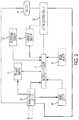
- FIG. 1is a schematic side view of an exemplary power tool.
- FIG. 2is simplified block diagram of an exemplary control system of the power tool of FIG. 1 .
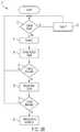
- FIG. 3Ais a flowchart showing a first exemplary control system and method for the power tool of FIG. 1 .
- FIG. 3Bis a flowchart showing a second exemplary control system and method for the power tool of FIG. 1 .
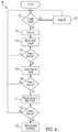
- FIG. 4is a flowchart showing a third exemplary control system method for the power tool of FIG. 1 .
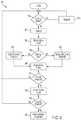
- FIG. 5is a flowchart showing a fourth exemplary control system method for the power tool of FIG. 1 .
- FIG. 6is a flowchart showing a fifth exemplary control system method for the power tool of FIG. 1 .
- an exemplary power tool 10is a hand held rotary hammer. While the following description is provided with reference to a rotary hammer, it is readily understood that the broader aspects of the present invention are applicable to other types of power tools having rotary shafts, such as drills, impact drivers, screwdrivers, saws, and hammers.
- the rotary hammerincludes a housing 20 and an output shaft or spindle 12 drivably coupled to an electric motor 14 (e.g., a brushless DC motor, a brushed DC motor, or an AC motor) received at least partially in the housing 20 .
- a chuck 16is coupled at one end of the spindle 12 ; whereas a drive shaft 18 of the electric motor 14 is connected via a transmission 22 to the other end of the spindle 12 .
- a power supply 26e.g., a DC battery pack or an AC mains supply
- Operation of the toolis controlled through the use an operator actuated trigger or switch 24 embedded in the handle of the tool.
- the switch 24regulates current flow from the power supply 26 to the motor 14 via a controller, microprocessor or microcontroller 36 and a motor control circuit 33 .
- the motor 14is a brushless DC motor and the motor control circuit 33 includes a power switching circuit (e.g., a three-phase bridge driver circuit including six controllable semiconductor power devices (e.g. FETs, BJTs, IGBTs, etc.) and a power control circuit (e.g., a gate driver circuit and a power supply regulator circuit).
- the power toolmay further include a temperature sensor.
- the transmission 22 of the rotary hammer 10may include a hammer drive arrangement and a mode change mechanism 35 configured to configure the rotary hammer 10 for operation in any one of a hammer only mode, a rotary drive only mode and a rotary hammering mode for changing the operation of the hammer drill.
- the mode change mechanism 35may include an external knob or switch 37 that enables the user to select among these modes of operation.
- the rotary hammer 10may also include a mode sensor 39 (e.g., a potentiometer) configured to detect a position of the switch 37 and determine which mode of operation has been selected by the user.
- a mode sensor 39e.g., a potentiometer
- the power tool 10includes a control system 30 to detect a kickback condition.
- the control system 30may include a rotational motion sensor 32 , a current sensor 28 , and the microcontroller or microprocessor 36 .
- the onset of a kickback conditionwill cause the power tool housing 20 to rotate in the operator's grasp.
- the rotational motion sensor 32detects any such rotational motion.
- the operating, principle of the rotational motion sensor 32is based on the Coriolis effect.
- the rotational motion sensoris comprised of a resonating mass.
- the resonating massWhen the power tool is subject to rotational motion about the axis of the spindle, the resonating mass will be laterally displaced in accordance with the Coriolis effect, such that the lateral displacement is directly proportional to the angular rate. It is noteworthy that the resonating motion of the mass and the lateral movement of the mass occur in a plane which is orientated perpendicular to the rotational axis of the rotary shaft. Capacitive sensing elements are then used to detect the lateral displacement and generate an applicable signal indicative of the lateral displacement.
- An exemplary rotational motion sensoris the ADXRS150 or ADXRS300 gyroscope device commercially available from Analog Devices. Other types of rotational motion sensors such as gyroscopes, accelerometers, and other MEMS devices may also be used.
- the microcontroller 36may determine the onset of a kickback condition based on the signal received from the rotational motion sensor 32 . For instance, the microcontroller 36 may determine that a kickback condition has occurred based on a determination that that value of the rotational sensor signal or a rate of change of the rotational sensor signal has exceeded a threshold value. When this occurs, the microcontroller 36 will initiate one or more protective operations intended to avoid and/or minimize any undesired rotation of the power tool, e.g., by shutting off or reducing power to the motor, by causing pulsing of the motor, and/or by actuating, a mechanical clutch. It is readily understood that other techniques for assessing the signal received from the rotational sensor are within the scope of the present invention.
- the microcontroller 36may also disable or delay initiation of the protective operation upon making a determination that the signal from the rotational sensor is likely to be providing a false indication of a kickback condition. For example, the microcontroller may receive a current signal from the current sensor 28 that indicates the amount of current being drawn by the motor. If the current is below a threshold value, the microcontroller 36 may determine that the power tool 10 is being operated under a no load condition or in hammer only mode, and therefore, may disregard any indication of a kickback condition received from the rotation sensor 32 . In addition, the microcontroller 36 may receive a mode signal from the mode sensor 39 that indicates which mode of operation has been selected by the user.
- the microcontrollermay disregard any indication of kickback received from the rotation sensor 32 , or may alter the rotational signal threshold for determining that a kickback condition has occurred. If the microcontroller determines that the signal from the rotational sensor is likely to be a false, the microcontroller may fail to initiate the protective operation or may delay initiation of the protective operation for a predetermined period of time to determine whether the user has regained control of the tool.
- a power supply circuit 29is coupled to the B+ and B ⁇ power line inputs from the power supply 26 and supplies a controlled. DC voltage to operate the microcontroller 36 and the motor 14 .
- the trigger switch 24supplies a trigger signal to the microcontroller 36 . This trigger signal indicates the position or setting of the trigger switch 24 as it is manually operated by the power tool operator.
- Drive current for operating the motor 14is controlled by a motor control circuit 33 .
- the motor control circuit 33is, in turn, controlled by a signal supplied by microcontroller 36 .
- the control system 30may include a reset circuit 44 which, when activated, causes the microcontroller 36 to be re-initialized.
- the current sensor 28is connected with the motor control circuit 33 and the motor 14 , in an exemplary embodiment, the current sensor 28 may be a low resistance, high wattage resistor.
- the voltage drop across the current sensor 28is measured as an indication of actual instantaneous motor current.
- the instantaneous motor currentmay supplied to an average current measuring circuit (not shown) which in turn may supply an average current value to the microcontroller 36 .
- the microcontroller 36may use the current signal to evaluate whether the rotation sensor is likely to give a false indication of a kickback condition and/or to confirm the indication of a kickback condition from the rotation sensor.
- the trigger switch 24supplies a trigger signal that varies in proportion to the switch setting to the microcontroller 36 .
- the microcontroller 36Based on this trigger signal, the microcontroller 36 generates a control signal to the motor control circuit 33 , which causes the motor to draw current and operate at a desired motor speed and direction (e.g., by PWM control).
- the current sensor 28monitors the motor current and provides a current signal indicative of the motor current to the microcontroller 36 .
- the rotational sensor 32senses rotational displacement, velocity or acceleration of the housing and provides a rotational signal indicative of these sensed values to the microcontroller.
- the mode sensor 39senses a position of the mode change knob 37 and provides a mode signal indicative of the selected mode to the microcontroller.
- the microcontroller 36determines whether a kickback determination is has occurred and whether such kickback condition is likely to be false. If the microcontroller determines that the kickback condition is not likely to be false and that a kickback condition has occurred, the microcontroller initiates one or more protective operations.
- the protective operationmay include one or more of (and are not limited to) disconnecting power to the motor 14 , reducing power to the motor 14 , braking the motor 14 , disengaging the motor 14 from the spindle 12 and actuating a clutch disposed between the motor 14 and the spindle 12 , or pulsing the motor 14 (e.g., in a manner described in U.S. Pat. No. 6,479,958, which is incorporated by reference).
- one or more of these protective operationsmay be initiated to prevent undesirable rotation of the tool 10 .
- step 52the microcontroller determines whether the trigger switch is closed to determine if the tool is operating. If the switch is not closed, then power is not being supplied to the motor as indicated at step 53 . In this case, there is no need to monitor for kickback conditions. Conversely, if the switch is closed, then power is being supplied to the motor as indicated at step 54 .
- the microcontrollermonitors the current signal that indicates the amount of motor current.
- the amount of motor currentis compared to a threshold amount stored in memory. If the amount of motor current is at or below the threshold (e.g., below 8 amps), then the microcontroller determines that the motor is not operating under a loaded condition the tool is not being used to drill into material or is being operated in hammer only mode), and any kickback indication of the rotational sensor is likely to be false. Therefore, the microcontroller will return to the start of the algorithm. On the other hand, if the motor current exceeds the current threshold, then the microcontroller determines that a kickback indication from the rotational sensor is likely to be valid.
- the microcontrollermay compare a mathematical function of the current signal (e.g., a first or second derivative of the current signal such as a rate of change of current) to a threshold value to make this determination.
- a mathematical function of the current signale.g., a first or second derivative of the current signal such as a rate of change of current
- the current threshold valuesmay vary depending on other tool conditions (e.g., a motor speed or the mode of the transmission).
- the microcontrollermonitors the rotation signal from the rotational motion sensor 32 , which may indicate the rotational displacement, rate, or acceleration of the tool housing.
- the microcontrollercompares the value of the rotational signal (or of a mathematical function of the rotational signal) to one or more predetermined thresholds. If the value is less than or equal to the threshold, the microcontroller determines that no kickback condition has occurred and returns to the beginning of this process. On the other hand, if the value exceeds the threshold, then the microcontroller determines that a kickback condition has occurred, and, at step 60 , initiates one or more protective operations. It is envisioned that one or more of rotational rate of the tool, rotational displacement, rotational acceleration, or some combination or mathematical function thereof as derived from the sensor signal may be used to determine the onset of a kickback condition.
- the microcontrollermay first monitor and determine whether the rotational signal exceeds a threshold value (indicating a kickback condition), and, only if a kickback condition is indicated, next monitor and determine whether the current signal indicates a false kickback determination.
- Steps 52 ′- 54 ′are substantially the same as steps 52 - 54 in the method 50 illustrated in FIG.
- the microcontrollermonitors the rotation signal from the rotational motion sensor 32 , which may indicate the rotational displacement, rate, or acceleration of the tool housing.
- the microcontrollercompares the value of the rotational signal (or of a mathematical function of the rotational signal) to one or more predetermined thresholds. If the value is less than or equal to the threshold, the microcontroller determines that no kickback condition has occurred and returns to the beginning of this process. On the other hand, if the value exceeds the threshold, then the microcontroller determines that a kickback condition has occurred. It is, envisioned that one or more of rotational rate of the tool, rotational displacement, rotational acceleration, or some combination or mathematical function thereof as derived from the sensor signal may be used to determine the onset of a kickback condition.
- the microcontrollerdetermines whether the detected kickback condition is likely to be false.
- the microcontrollermonitors the current signal that indicates the amount of motor current.
- the amount of motor currentis compared to a threshold amount stored in memory. If the amount of motor current is at or below the threshold (e.g., below 8 amps), then the microcontroller determines that the motor is not operating under a loaded condition (e.g., the tool is not being used to drill into material or is being operated in hammer only mode), and any kickback indication of the rotational sensor is likely to be false. Therefore, the microcontroller will return to the start of the algorithm.
- the microcontrollerdetermines that a kickback indication from the rotational sensor is likely to be valid and, at step 60 , initiates one or more protective operations.
- the microcontrollermay compare a mathematical function of the current signal (e.g., a first or second derivative of the current signal such as a rate of change of current) to a threshold value to make this determination.
- the current threshold valuesmay vary depending on other tool conditions (e.g., a motor speed or the mode of the transmission).
- Steps 152 - 159are substantially the same as steps 52 - 59 in the method 50 illustrated in FIG. 3A . If, at step 159 , the microcontroller determines that the value of the rotational signal (or of a mathematical function of the rotational signal) exceeds one or more predetermined thresholds, then at steps 161 - 162 the microcontroller again uses the motor current signal to confirm that the kickback condition is valid. At step 161 , the microcontroller determines the rate of change of the motor current.
- step 162if the rate of change of motor current is positive and exceeds a predetermined threshold, then one, or more protective operations are initiated at 160 . If either the rate of change is not positive or the rate of change does not exceed the threshold, then processing control returns to the beginning of the algorithm. In this case, a sudden change in the current draw is optionally used to confirm the onset of the kickback condition. It is envisioned that inputs from, other sensors, such as a temperature sensor, may be used in a similar manner.
- Steps 252 - 254are substantially the same as steps 52 - 54 and 152 - 154 in the methods 50 and 150 illustrated in FIGS. 3A and 4 .
- the microcontrollermonitors the mode signal from the mode sensor to determine the mode of operation selected by the user.
- the microcontrollerdetermines whether the hammer only mode has been selected. If so, then the microcontroller disregards any signals from the motor current sensor and the rotational sensor that may indicate a kickback condition, and returns to the beginning of the algorithm.
- steps 256 - 260are substantially the same as steps 56 - 60 and 156 - 160 in the methods 50 , 150 illustrated in FIGS. 3A and 4 .
- the microcontrollerdetermines whether a valid kickback condition has occurred, and, if so, initiates one or more protective operations.
- the method 250may also optionally include confirmatory steps 161 - 162 of the method 150 of FIG. 4 between steps 259 and 260 to use the rate of change of motor current to confirm that a valid kickback condition has occurred before initiating the protective operation(s) at step 260 .
- Steps 352 - 354are substantially the same as steps 52 - 54 , 152 - 154 , and 162 - 164 in the methods 50 , 150 , and 250 illustrated in FIGS. 3A, 4, and 5 .
- the microcontrollermonitors the mode signal from the mode sensor to determine the mode of operation selected by the user.
- the microcontrollerdetermines whether the hammer only mode has been selected, if so, then at step 365 , the microcontroller sets a first threshold value for current. If not, then at step 366 , the microcontroller sets a second threshold value for current, which may be the same as or different from the first threshold value.
- step 356the microcontroller monitors the current signal that indicates the amount of motor current.
- step 357the amount of motor current is compared to either the first threshold current value set in step 365 or the second threshold value set in step 366 . If the amount of motor current is at or below the threshold (e.g., below 10 amps for hammer only mode or below 8 amps for drill mode or hammer drill mode), then the microcontroller determines that the motor is not operating under a sufficiently loaded condition, and any kickback indication of the rotational sensor is likely to be false. Therefore, the microcontroller will return to the start of the algorithm. On the other hand, if the motor current exceeds the set current threshold, then the microcontroller determines that a kickback indication from the rotational sensor is likely to be valid.
- the thresholde.g., below 10 amps for hammer only mode or below 8 amps for drill mode or hammer drill mode
- the microcontrollerthen proceeds to steps 258 - 260 , which are substantially the same as steps 58 - 60 , 158 - 160 , and 258 - 260 in the methods 50 , 150 , 250 illustrated in FIGS. 3A, 4, and 5 . In doing so, the microcontroller determines whether a valid kickback condition has occurred, and, if so, initiates one or more protective operations.
- the method 350may also optionally include confirmatory steps 161 - 162 of the method 150 of FIG. 4 between steps 359 and 360 to use the rate of change of motor current to confirm that a valid kickback condition has occurred before initiating the protective operation(s) at step 360 .
- each of the above control schemesmay initiate different protective operations for different tool conditions.
- the amount of angular displacement experienced by the toolmay dictate different protective operations.
- angular displacementis within a first range (e.g., less than 31°)
- the operatormay be presumed to have control of the tool and thus no protective operations are needed.
- the angular displacementexceeds this first range, it may be presumed that the tool has encountered a kickback condition and therefore some protective operation may be needed.
- this second range of angular displacemente.g., between 30° to 90°
- the control schememay initiate a pulse mode in hope of breaking through the restrictions that are causing the impending kickback condition.
- the angular displacementexceeds the second range (e.g., greater than 90°)
- the control schemesuch as disconnecting the power to the motor.
- three or more ranges of displacementmay be defined for a given power tool.
- protective operationsmay be initiated based on the angular displacement or a combination of parameters, such as angular acceleration, angular velocity, motor current, rate of change of motor current, motor temperature, switch temperature, etc. It is readily understood that the number and size of the ranges may vary for different control schemes and/or different types of tools. It is also envisioned that different protective operations may be initiated based on ranges of other parameters (e.g., ranges of angular velocity). Likewise, one or more protective operations may be associated with different ranges (i.e., tool conditions). Such additional ranges and protective operations are described in more detail in U.S. Pat. No. 7,410,006, which is incorporated by reference.
- Determination of a kickback conditionmay be based on other types of criteria.
- a kickback conditionmay be assessed based on the rotational energy experienced by the power tool.
- the rate of angular displacementcould be measured by a rotational motion sensor; whereas, the moment of inertia of the tool (I TOOL ) could be preprogrammed into the controller based on the mass properties of the power tool (e.g., mass, rotation inertia and a center of gravity position) and a distance measure between the center of gravity position and the spindle, axis.
- I TOOLmoment of inertia of the tool
- Initiating a protective operation based on E ⁇ TOOLis desirable because the energy condition is not tool specific and therefore could be applied to a variety of anti-kickback applications.
- Other criteria for determining a kickback conditionare also within the broader aspects of the present invention.
- Example embodimentshave been provided so that this disclosure will be thorough, and to fully convey the scope to those who are skilled in the art. Numerous specific details are set forth such as examples of specific components, devices, and methods, to provide a thorough understanding of embodiments of the present disclosure. It will be apparent to those skilled in the art that specific details need not be employed, that example embodiments may be embodied in many different forms and that neither should be construed to limit the scope of the disclosure. In some example embodiments, well-known processes, well-known device structures, and well-known technologies are not described in detail.
- first, second, third, etc.may be used herein to describe various elements, components, regions, layers and/or sections, these elements, components, regions, layers and/or sections should not be limited by these terms. These terms may be only used to distinguish one element, component, region, layer or section from another region, layer or section. Terms such as “first,” “second,” and other numerical terms when used herein do not imply a sequence or order unless dearly indicated by the context. Thus, a first element, component, region, layer or section discussed below could be termed a second element, component, region, layer or section without departing from the teachings of the example embodiments.
Landscapes
- Engineering & Computer Science (AREA)
- Mechanical Engineering (AREA)
- Physics & Mathematics (AREA)
- General Physics & Mathematics (AREA)
- General Engineering & Computer Science (AREA)
- Radar, Positioning & Navigation (AREA)
- Remote Sensing (AREA)
- Percussive Tools And Related Accessories (AREA)
Abstract
Description
This application claims priority, under 35 U.S.C. § 119(e), to U.S. Provisional Application No. 62/352,118, filed Jun. 20, 2016, titled “Power Tool with Anti-Kickback Control System,” which is incorporated by reference.
This application relates to a power tool with an anti-kickback control system.
U.S. Pat. No. 7,410,006 to Zhang and U.S. Pat. No. 8,316,958 to Schell, which are incorporated by reference, each disclose a power tool having a control system with a rotational motion sensor for detecting the onset of a kickback condition of a power tool and initiating a protective operation when a kickback condition is detected. However, nuisance initiation of the protective operation(s) (also known as false trips or indications) may occur when the tool is being operated under certain parameters or conditions (e.g., under no load or in hammer only mode).
In an aspect, a power tool has a motor, a transmission, an output, and a control system configured to detect onset of a valid kickback condition and, upon detecting such a condition, and to initiate one or more protective operations. The control system includes a current sensor that senses motor current and a rotational motion sensor that senses rotational movement of the tool housing. The control system uses the signal from the current sensor to determine whether the tool is being operated in a manner (e.g., under a no load condition or in a hammer only mode) in which false indications of a kickback condition are likely to occur. The control system uses the signal from rotation sensor to determine whether an uncontrolled kickback condition has occurred. Based on determinations that a sensed kickback condition is likely to be valid and that a kickback condition has been sensed, the control system initiates one or more protective operations to avoid undesirable rotation of the power tool. The protective operation(s) may include one or more of interrupting power to the motor, reducing power to the motor, pulsing the motor, braking the motor, and/or actuating a mechanical or electromechanical clutch.
In another aspect, a method for initiating a protective response in a power tool having a rotary shaft, a current sensor, and a rotary motion sensor is disclosed. The method includes the steps of arranging the rotational motion sensor in the power tool, monitoring current delivered to the motor using the current sensor disposed in the power tool, determining whether the a kickback condition is likely to be valid based on input from the current sensor, monitoring rotational motion of the rotational motion sensor about a longitudinal axis of the rotary shaft using the rotational motion sensor disposed in the power tool, determining rotational motion of the rotational motion sensor with respect to the longitudinal axis of the rotary shaft using a controller disposed in the power tool and based on input from the rotational motion sensor, and initiating a protective operation upon determining that a kickback condition is likely to be, valid and upon determining the rotational motion from the rotational motion sensor.
In another aspect, a method for initiating a protective response in a power tool having a rotary shaft rotatably driven by a motor is disclosed. The method includes, the steps of monitoring current delivered to the motor using a current sensor disposed in the power tool, determining whether a detected kickback condition is likely to be valid based on input to a controller from the current sensor, monitoring rotational motion of the tool about a longitudinal axis of the shaft using a rotation motion sensor disposed in the power tool, determining whether a kickback condition has occurred based on input to the controller disposed in the power tool from the rotation motion sensor, and reducing motor speed to a non-zero value upon determining that a detected kickback condition is likely to be valid and upon determining that a kickback condition has occurred.
In another aspect, a power tool having an output shaft includes a control system. A motor is disposed in the power tool and drivably connected to the output shaft to impart rotary motion thereto. A current sensor is disposed in the power tool and operable to detect current delivered to the motor. A rotational motion sensor is disposed in the power tool and operable to detect rotational motion of the tool about a longitudinal axis of the output shaft. A controller is configured to receive a first signal indicative of current delivered to the motor from the current senor and a second signal indicative of rotational motion of the tool from the rotational motion sensor. Based on the first and second signals, the controller is operable to determine whether a kickback condition has occurred and whether the kickback condition is likely to be valid, and is operable to set rotational speed of the motor to a non-zero value based detection of a kickback condition that is likely to be valid.
In another aspect, a power tool includes a housing, a motor received in the housing, an output driven by the motor, and a control system. The control system includes a rotational motion sensor configured to generate a rotational motion signal that corresponds to a rotational motion of the housing about an axis, a current sensor configured to generate a motor current signal that corresponds to an amount of current drawn by the motor, and a control circuit that is configured to receive the rotational motion signal and the motor current signal and to control operation of the motor. The control circuit is configured: (a) to determine, based on the current signal, whether a detected kickback condition is likely to be false; (b) to determine, based upon the rotational motion signal, whether an uncontrolled kickback condition has occurred; and (c) to initiate one or more protective operations upon determining that an uncontrolled kickback condition has occurred and is not likely to be false.
Implementations of this aspect may include one or more of the following features. The one or more protective operations includes one or more of interrupting power to the motor, reducing power to the motor to a non-zero value, pulsing the motor, braking the motor, and actuating a clutch. The rotational motion sensor may include one or more of a gyroscope and an accelerometer. The current sensor may include a low resistance, high wattage resistor. The control circuit may include one or more of a controller, a microcontroller, and a motor control circuit. The control circuit may be configured to determine that the uncontrolled kickback condition has occurred when the rotational motion signal indicates that at least one of an angular rotation, an angular velocity, and an angular acceleration of the housing exceeds a threshold value. The control circuit may be configured to determine that the detected uncontrolled kickback condition is likely to be false when the current signal indicates that at least one of the amount of current drawn by the motor and a rate of change of the amount of current drawn by the motor is less than a threshold value.
The power tool may further include a mode change mechanism configured to select among a hammer only mode, a rotary drive only mode, and a rotary hammering mode, and a mode change sensor configured to generate a mode change signal that corresponds to the selected mode. The control circuit may be configured to prevent initiation of the one or more protective operations when the mode change signal indicates that the hammer only mode has been selected. The control circuit may be configured to determine that the detected uncontrolled kickback condition is likely to be false when the current signal indicates that the amount of current drawn by the motor is less than a current threshold value, and the control circuit is configured to set the current threshold value at a first current threshold value when the mode change signal indicates that the hammer only mode has been selected and at a different second current threshold value when the mode change signal indicates that the hammer only mode has not been selected.
In another aspect, a method for initiating a protective response in a power tool having a housing, a motor received in the housing, an output driven by the motor, a current sensor, and a rotational motion sensor is disclosed. The method includes receiving a current signal from the current sensor that corresponds to an amount of current drawn by the motor; determining whether a detected kickback condition is likely to be false based upon the current signal; receiving a rotational motion signal from the rotational motion sensor that corresponds to a rotational motion of the housing about an axis; determining whether an uncontrolled kickback condition has occurred based upon the rotational motion signal; and initiating one or more protective operations upon determining that an uncontrolled kickback condition has occurred and is not likely to be false.
Implementations of this aspect may include one or more of the following features. Initiating the one or more protective operations may include one or more of interrupting power to the motor, reducing power to the motor to a non-zero value, pulsing the motor, braking the motor, and actuating a clutch. The rotational motion sensor may include one or more of a gyroscope and an accelerometer. The current sensor may include a low resistance, high wattage resistor. Determining that an uncontrolled kickback condition has occurred may include determining that at least one of an angular rotation, an angular velocity, and an angular acceleration of the housing exceeds a threshold value. Determining that a detected uncontrolled kickback condition is likely to be false may include determining that at least one of the amount of current drawn by the motor and a rate of change of the amount of current drawn by the motor is less than a threshold value. Receiving a current signal and determining whether a detected kickback condition is likely to be false may be performed before or after receiving a rotational motion signal, and determining whether an uncontrolled kickback condition has occurred.
The power tool may further include a mode change mechanism configured to select among a hammer only mode, a rotary drive only mode, and a rotary hammering mode, and a mode change sensor configured to generate a mode change signal that corresponds to the selected mode. The method may further include preventing the initiating of the one or more protective operations when the mode change signal indicates that the hammer only mode has been selected. Determining that the detected uncontrolled kickback condition is likely to be false may include determining when the current signal indicates that the amount of current drawn by the motor is less than a current threshold value. The method may further include setting the current threshold value at a first current threshold value when the mode change signal indicates that the hammer only mode has been selected and at a different second current threshold value when the mode change signal indicates that the hammer only mode has not been selected.
Advantages may include one or more of the following. The power tool may avoid false or nuisance trips that may occur when the tool is operating under a no load condition and/or when operating in a hammer only mode. These and other advantages and features will be apparent from the description, the drawings, and the claims.
Referring toFIG. 1 , anexemplary power tool 10 is a hand held rotary hammer. While the following description is provided with reference to a rotary hammer, it is readily understood that the broader aspects of the present invention are applicable to other types of power tools having rotary shafts, such as drills, impact drivers, screwdrivers, saws, and hammers.
The rotary hammer includes ahousing 20 and an output shaft orspindle 12 drivably coupled to an electric motor14 (e.g., a brushless DC motor, a brushed DC motor, or an AC motor) received at least partially in thehousing 20. Achuck 16 is coupled at one end of thespindle 12; whereas adrive shaft 18 of theelectric motor 14 is connected via atransmission 22 to the other end of thespindle 12. A power supply26 (e.g., a DC battery pack or an AC mains supply) is coupled to apower supply circuit 34 that is disposed in ahandle 31 of thehousing 20. Operation of the tool is controlled through the use an operator actuated trigger or switch24 embedded in the handle of the tool. Theswitch 24 regulates current flow from thepower supply 26 to themotor 14 via a controller, microprocessor ormicrocontroller 36 and amotor control circuit 33. In one implementation, themotor 14 is a brushless DC motor and themotor control circuit 33 includes a power switching circuit (e.g., a three-phase bridge driver circuit including six controllable semiconductor power devices (e.g. FETs, BJTs, IGBTs, etc.) and a power control circuit (e.g., a gate driver circuit and a power supply regulator circuit). The power tool may further include a temperature sensor.
Thetransmission 22 of therotary hammer 10 may include a hammer drive arrangement and amode change mechanism 35 configured to configure therotary hammer 10 for operation in any one of a hammer only mode, a rotary drive only mode and a rotary hammering mode for changing the operation of the hammer drill. Themode change mechanism 35 may include an external knob or switch37 that enables the user to select among these modes of operation. Therotary hammer 10 may also include a mode sensor39 (e.g., a potentiometer) configured to detect a position of theswitch 37 and determine which mode of operation has been selected by the user. An exemplary hammer drive arrangement, mode change mechanism and knob are described in U.S. Pat. No. 6,666,284, which is incorporated by reference, although other implementations are well known in the art. Although a few primary components of the rotary hammer are discussed above, it is readily understood that other components known in the art may be needed to construct an operational rotary hammer.
Thepower tool 10 includes acontrol system 30 to detect a kickback condition. Thecontrol system 30 may include arotational motion sensor 32, acurrent sensor 28, and the microcontroller ormicroprocessor 36. In some instances, the onset of a kickback condition will cause thepower tool housing 20 to rotate in the operator's grasp. Therotational motion sensor 32 detects any such rotational motion.
In an embodiment, the operating, principle of therotational motion sensor 32 is based on the Coriolis effect. Briefly, the rotational motion sensor is comprised of a resonating mass. When the power tool is subject to rotational motion about the axis of the spindle, the resonating mass will be laterally displaced in accordance with the Coriolis effect, such that the lateral displacement is directly proportional to the angular rate. It is noteworthy that the resonating motion of the mass and the lateral movement of the mass occur in a plane which is orientated perpendicular to the rotational axis of the rotary shaft. Capacitive sensing elements are then used to detect the lateral displacement and generate an applicable signal indicative of the lateral displacement. An exemplary rotational motion sensor is the ADXRS150 or ADXRS300 gyroscope device commercially available from Analog Devices. Other types of rotational motion sensors such as gyroscopes, accelerometers, and other MEMS devices may also be used.
Themicrocontroller 36 may determine the onset of a kickback condition based on the signal received from therotational motion sensor 32. For instance, themicrocontroller 36 may determine that a kickback condition has occurred based on a determination that that value of the rotational sensor signal or a rate of change of the rotational sensor signal has exceeded a threshold value. When this occurs, themicrocontroller 36 will initiate one or more protective operations intended to avoid and/or minimize any undesired rotation of the power tool, e.g., by shutting off or reducing power to the motor, by causing pulsing of the motor, and/or by actuating, a mechanical clutch. It is readily understood that other techniques for assessing the signal received from the rotational sensor are within the scope of the present invention.
Themicrocontroller 36 may also disable or delay initiation of the protective operation upon making a determination that the signal from the rotational sensor is likely to be providing a false indication of a kickback condition. For example, the microcontroller may receive a current signal from thecurrent sensor 28 that indicates the amount of current being drawn by the motor. If the current is below a threshold value, themicrocontroller 36 may determine that thepower tool 10 is being operated under a no load condition or in hammer only mode, and therefore, may disregard any indication of a kickback condition received from therotation sensor 32. In addition, themicrocontroller 36 may receive a mode signal from themode sensor 39 that indicates which mode of operation has been selected by the user. If themode sensor 39 indicates that the user has selected a hammer only mode, the microcontroller may disregard any indication of kickback received from therotation sensor 32, or may alter the rotational signal threshold for determining that a kickback condition has occurred. If the microcontroller determines that the signal from the rotational sensor is likely to be a false, the microcontroller may fail to initiate the protective operation or may delay initiation of the protective operation for a predetermined period of time to determine whether the user has regained control of the tool.
Operation of anexemplary control circuit 30 is further described below in relation toFIG. 2 . Apower supply circuit 29 is coupled to the B+ and B− power line inputs from thepower supply 26 and supplies a controlled. DC voltage to operate themicrocontroller 36 and themotor 14. Thetrigger switch 24 supplies a trigger signal to themicrocontroller 36. This trigger signal indicates the position or setting of thetrigger switch 24 as it is manually operated by the power tool operator. Drive current for operating themotor 14 is controlled by amotor control circuit 33. Themotor control circuit 33 is, in turn, controlled by a signal supplied bymicrocontroller 36. If desired, thecontrol system 30 may include areset circuit 44 which, when activated, causes themicrocontroller 36 to be re-initialized.
Thecurrent sensor 28 is connected with themotor control circuit 33 and themotor 14, in an exemplary embodiment, thecurrent sensor 28 may be a low resistance, high wattage resistor. The voltage drop across thecurrent sensor 28 is measured as an indication of actual instantaneous motor current. The instantaneous motor current may supplied to an average current measuring circuit (not shown) which in turn may supply an average current value to themicrocontroller 36. Themicrocontroller 36 may use the current signal to evaluate whether the rotation sensor is likely to give a false indication of a kickback condition and/or to confirm the indication of a kickback condition from the rotation sensor.
In operation, thetrigger switch 24 supplies a trigger signal that varies in proportion to the switch setting to themicrocontroller 36. Based on this trigger signal, themicrocontroller 36 generates a control signal to themotor control circuit 33, which causes the motor to draw current and operate at a desired motor speed and direction (e.g., by PWM control). During operation, thecurrent sensor 28 monitors the motor current and provides a current signal indicative of the motor current to themicrocontroller 36. In addition, therotational sensor 32 senses rotational displacement, velocity or acceleration of the housing and provides a rotational signal indicative of these sensed values to the microcontroller. Finally, themode sensor 39 senses a position of themode change knob 37 and provides a mode signal indicative of the selected mode to the microcontroller. Based on, the current signal, the rotational signal and the mode signal, themicrocontroller 36 determines whether a kickback determination is has occurred and whether such kickback condition is likely to be false. If the microcontroller determines that the kickback condition is not likely to be false and that a kickback condition has occurred, the microcontroller initiates one or more protective operations.
The protective operation may include one or more of (and are not limited to) disconnecting power to themotor 14, reducing power to themotor 14, braking themotor 14, disengaging themotor 14 from thespindle 12 and actuating a clutch disposed between themotor 14 and thespindle 12, or pulsing the motor14 (e.g., in a manner described in U.S. Pat. No. 6,479,958, which is incorporated by reference). Depending on the size and orientation of thetool 10, one or more of these protective operations may be initiated to prevent undesirable rotation of thetool 10.
Referring toFIG. 3A , anexemplary method 50 for determining the onset of valid kickback condition is illustrated. First, atstep 52, the microcontroller determines whether the trigger switch is closed to determine if the tool is operating. If the switch is not closed, then power is not being supplied to the motor as indicated atstep 53. In this case, there is no need to monitor for kickback conditions. Conversely, if the switch is closed, then power is being supplied to the motor as indicated atstep 54.
If the power is on, then atstep 56, the microcontroller monitors the current signal that indicates the amount of motor current. Atstep 57, the amount of motor current is compared to a threshold amount stored in memory. If the amount of motor current is at or below the threshold (e.g., below 8 amps), then the microcontroller determines that the motor is not operating under a loaded condition the tool is not being used to drill into material or is being operated in hammer only mode), and any kickback indication of the rotational sensor is likely to be false. Therefore, the microcontroller will return to the start of the algorithm. On the other hand, if the motor current exceeds the current threshold, then the microcontroller determines that a kickback indication from the rotational sensor is likely to be valid. In other embodiments, atstep 57, the microcontroller may compare a mathematical function of the current signal (e.g., a first or second derivative of the current signal such as a rate of change of current) to a threshold value to make this determination. In yet other embodiments, the current threshold values may vary depending on other tool conditions (e.g., a motor speed or the mode of the transmission).
Next, atstep 58, the microcontroller monitors the rotation signal from therotational motion sensor 32, which may indicate the rotational displacement, rate, or acceleration of the tool housing. Atstep 59, the microcontroller compares the value of the rotational signal (or of a mathematical function of the rotational signal) to one or more predetermined thresholds. If the value is less than or equal to the threshold, the microcontroller determines that no kickback condition has occurred and returns to the beginning of this process. On the other hand, if the value exceeds the threshold, then the microcontroller determines that a kickback condition has occurred, and, atstep 60, initiates one or more protective operations. It is envisioned that one or more of rotational rate of the tool, rotational displacement, rotational acceleration, or some combination or mathematical function thereof as derived from the sensor signal may be used to determine the onset of a kickback condition.
It should be understood that the order of operations of the algorithm may be changed. For example, referring toFIG. 3B , in anotherexemplary method 50′ for determining the onset of a non-false kickback condition, the microcontroller may first monitor and determine whether the rotational signal exceeds a threshold value (indicating a kickback condition), and, only if a kickback condition is indicated, next monitor and determine whether the current signal indicates a false kickback determination.Steps 52′-54′ are substantially the same as steps52-54 in themethod 50 illustrated inFIG. 3A , If, atstep 54′, the power is on, then atstep 56′, the microcontroller monitors the rotation signal from therotational motion sensor 32, which may indicate the rotational displacement, rate, or acceleration of the tool housing. Atstep 57′, the microcontroller compares the value of the rotational signal (or of a mathematical function of the rotational signal) to one or more predetermined thresholds. If the value is less than or equal to the threshold, the microcontroller determines that no kickback condition has occurred and returns to the beginning of this process. On the other hand, if the value exceeds the threshold, then the microcontroller determines that a kickback condition has occurred. It is, envisioned that one or more of rotational rate of the tool, rotational displacement, rotational acceleration, or some combination or mathematical function thereof as derived from the sensor signal may be used to determine the onset of a kickback condition.
Next, the microcontroller determines whether the detected kickback condition is likely to be false. Atstep 58′, the microcontroller monitors the current signal that indicates the amount of motor current. Atstep 59′, the amount of motor current is compared to a threshold amount stored in memory. If the amount of motor current is at or below the threshold (e.g., below 8 amps), then the microcontroller determines that the motor is not operating under a loaded condition (e.g., the tool is not being used to drill into material or is being operated in hammer only mode), and any kickback indication of the rotational sensor is likely to be false. Therefore, the microcontroller will return to the start of the algorithm. On the other hand, if the motor current exceeds the current threshold, then the microcontroller determines that a kickback indication from the rotational sensor is likely to be valid and, atstep 60, initiates one or more protective operations. In other embodiments, atstep 57′, the microcontroller may compare a mathematical function of the current signal (e.g., a first or second derivative of the current signal such as a rate of change of current) to a threshold value to make this determination. In yet other embodiments, the current threshold values may vary depending on other tool conditions (e.g., a motor speed or the mode of the transmission).
Referring, toFIG. 4 , anotherexemplary method 150 for determining the onset of a non-false kickback condition is illustrated. Steps152-159 are substantially the same as steps52-59 in themethod 50 illustrated inFIG. 3A . If, atstep 159, the microcontroller determines that the value of the rotational signal (or of a mathematical function of the rotational signal) exceeds one or more predetermined thresholds, then at steps161-162 the microcontroller again uses the motor current signal to confirm that the kickback condition is valid. Atstep 161, the microcontroller determines the rate of change of the motor current. Atstep 162, if the rate of change of motor current is positive and exceeds a predetermined threshold, then one, or more protective operations are initiated at160. If either the rate of change is not positive or the rate of change does not exceed the threshold, then processing control returns to the beginning of the algorithm. In this case, a sudden change in the current draw is optionally used to confirm the onset of the kickback condition. It is envisioned that inputs from, other sensors, such as a temperature sensor, may be used in a similar manner.
Referring toFIG. 5 , anotherexemplary method 250 for determining the onset of a non-false kickback condition, is illustrated. Steps252-254 are substantially the same as steps52-54 and152-154 in themethods FIGS. 3A and 4 . Atstep 263, after determining that the power is on, the microcontroller monitors the mode signal from the mode sensor to determine the mode of operation selected by the user. Atstep 264, the microcontroller determines whether the hammer only mode has been selected. If so, then the microcontroller disregards any signals from the motor current sensor and the rotational sensor that may indicate a kickback condition, and returns to the beginning of the algorithm. If not, then the microcontroller proceeds to steps256-260, which are substantially the same as steps56-60 and156-160 in themethods FIGS. 3A and 4 . In doing so, the microcontroller determines whether a valid kickback condition has occurred, and, if so, initiates one or more protective operations. Themethod 250 may also optionally include confirmatory steps161-162 of themethod 150 ofFIG. 4 betweensteps step 260.
Referring toFIG. 6 , anotherexemplary method 350 for determining the onset of a non-false kickback condition is illustrated. Steps352-354 are substantially the same as steps52-54,152-154, and162-164 in themethods FIGS. 3A, 4, and 5 . Atstep 363, after determining that the power is on, the microcontroller monitors the mode signal from the mode sensor to determine the mode of operation selected by the user. Atstep 364, the microcontroller determines whether the hammer only mode has been selected, if so, then atstep 365, the microcontroller sets a first threshold value for current. If not, then atstep 366, the microcontroller sets a second threshold value for current, which may be the same as or different from the first threshold value.
After either ofsteps step 357, the amount of motor current is compared to either the first threshold current value set instep 365 or the second threshold value set instep 366. If the amount of motor current is at or below the threshold (e.g., below 10 amps for hammer only mode or below 8 amps for drill mode or hammer drill mode), then the microcontroller determines that the motor is not operating under a sufficiently loaded condition, and any kickback indication of the rotational sensor is likely to be false. Therefore, the microcontroller will return to the start of the algorithm. On the other hand, if the motor current exceeds the set current threshold, then the microcontroller determines that a kickback indication from the rotational sensor is likely to be valid.
The microcontroller then proceeds to steps258-260, which are substantially the same as steps58-60,158-160, and258-260 in themethods FIGS. 3A, 4, and 5 . In doing so, the microcontroller determines whether a valid kickback condition has occurred, and, if so, initiates one or more protective operations. Themethod 350 may also optionally include confirmatory steps161-162 of themethod 150 ofFIG. 4 betweensteps step 360.
In another aspect, each of the above control schemes may initiate different protective operations for different tool conditions. For example, the amount of angular displacement experienced by the tool may dictate different protective operations. When angular displacement is within a first range (e.g., less than 31°), the operator may be presumed to have control of the tool and thus no protective operations are needed. When the angular displacement exceeds this first range, it may be presumed that the tool has encountered a kickback condition and therefore some protective operation may be needed. In this second range of angular displacement (e.g., between 30° to 90°), the control scheme may initiate a pulse mode in hope of breaking through the restrictions that are causing the impending kickback condition. In contrast, when the angular displacement exceeds the second range (e.g., greater than 90°), it may be presumed that the operator has lost control of the tool. In this instance, a different protective operation may be initiated by the control scheme, such as disconnecting the power to the motor.
Depending on the complexity of the control scheme, three or more ranges of displacement may be defined for a given power tool. Within a range, protective operations may be initiated based on the angular displacement or a combination of parameters, such as angular acceleration, angular velocity, motor current, rate of change of motor current, motor temperature, switch temperature, etc. It is readily understood that the number and size of the ranges may vary for different control schemes and/or different types of tools. It is also envisioned that different protective operations may be initiated based on ranges of other parameters (e.g., ranges of angular velocity). Likewise, one or more protective operations may be associated with different ranges (i.e., tool conditions). Such additional ranges and protective operations are described in more detail in U.S. Pat. No. 7,410,006, which is incorporated by reference.
Determination of a kickback condition may be based on other types of criteria. For example, a kickback condition may be assessed based on the rotational energy experienced by the power tool. In this example, rotational energy is defined as Eω−TOOL=(I)(ωTOOL)2, where I is the moment of inertia and ωTOOLis the angular velocity. For this computation, the rate of angular displacement could be measured by a rotational motion sensor; whereas, the moment of inertia of the tool (ITOOL) could be preprogrammed into the controller based on the mass properties of the power tool (e.g., mass, rotation inertia and a center of gravity position) and a distance measure between the center of gravity position and the spindle, axis. Initiating a protective operation based on Eω−TOOLis desirable because the energy condition is not tool specific and therefore could be applied to a variety of anti-kickback applications. Other criteria for determining a kickback condition are also within the broader aspects of the present invention.
Example embodiments have been provided so that this disclosure will be thorough, and to fully convey the scope to those who are skilled in the art. Numerous specific details are set forth such as examples of specific components, devices, and methods, to provide a thorough understanding of embodiments of the present disclosure. It will be apparent to those skilled in the art that specific details need not be employed, that example embodiments may be embodied in many different forms and that neither should be construed to limit the scope of the disclosure. In some example embodiments, well-known processes, well-known device structures, and well-known technologies are not described in detail.
The terminology used herein is for the purpose of describing particular example embodiments only and is not, intended to be limiting. As used herein, the singular forms “a,” “an,” and “the” may be intended to include the plural forms as well, unless the context clearly indicates otherwise. The terms “comprises,” “comprising,” “including,” and “having,” are inclusive and therefore specify the presence of stated features, integers, steps, operations, elements, and/or components, but do not preclude the presence or addition of one or more other features, integers, steps, operations, elements, components, and/or groups thereof. The method steps, processes, and operations described herein are not to be construed as necessarily requiring their performance in the particular order discussed or illustrated, unless specifically identified as an order of performance. It is also to be understood that additional or alternative steps may be employed.
When an element or layer is referred to as being “on,” “engaged to,” “connected to,” or “coupled to” another element or layer, it may be directly on, engaged, connected or coupled to the other element or layer, or intervening elements or layers may be present. In contrast, when an element is referred to as being “directly on,” “directly engaged to,” “directly connected to,” or “directly coupled to” another element or layer, there may be no intervening elements or layers present, Other words used to describe the relationship between elements should be interpreted in a like fashion (e.g., “between” versus “directly between,” “adjacent” versus “directly adjacent,” etc.). As used herein, the term “and/or” includes any and all combinations of one or more of the associated listed items.
Although the terms first, second, third, etc. may be used herein to describe various elements, components, regions, layers and/or sections, these elements, components, regions, layers and/or sections should not be limited by these terms. These terms may be only used to distinguish one element, component, region, layer or section from another region, layer or section. Terms such as “first,” “second,” and other numerical terms when used herein do not imply a sequence or order unless dearly indicated by the context. Thus, a first element, component, region, layer or section discussed below could be termed a second element, component, region, layer or section without departing from the teachings of the example embodiments.
Terms of degree such as “generally,” “substantially,” “approximately,” and “about” may be used herein when describing the relative positions, sizes, dimensions, or values of various elements, components, regions, layers and/or sections. These terms mean that such relative positions, sizes, dimensions, or values are within the defined range or comparison (e.g., equal or close to equal) with sufficient precision as would be understood by one of ordinary skill in the art in the context of the various elements, components, regions, layers and/or sections being described.
Claims (16)
1. A power tool comprising:
a housing;
a motor received in the housing;
an output driven by the motor; and
a control system that includes a rotational motion sensor configured to generate a rotational motion signal that corresponds to a rotational motion of the housing about an axis, a current sensor configured to generate a motor current signal that corresponds to an amount of current drawn by the motor, and a control circuit that is configured to receive the rotational motion signal and the motor current signal and to control operation of the motor,
wherein the control circuit is configured: (a) to determine, based on the current signal, that a detected kickback condition is likely to be false when the current signal indicates that at least one of the amount of current drawn by the motor and a rate of change of the amount of current drawn by the motor is less than a first threshold value; (b) to determine, based upon the rotational motion signal, that an uncontrolled kickback condition has occurred when the rotational motion signal indicates that at least one of an angular rotation, an angular velocity, and an angular acceleration of the housing exceeds a second threshold value; and (c) to initiate one or more protective operations upon determining that an uncontrolled kickback condition has occurred and is not likely to be false.
2. The power tool ofclaim 1 , wherein the one or more protective operations includes one or more of interrupting power to the motor, reducing power to the motor to a non-zero value, pulsing the motor, braking the motor, and actuating a clutch.
3. The power tool ofclaim 1 , wherein the rotational motion sensor comprises one or more of a gyroscope and an accelerometer.
4. The power tool ofclaim 1 , wherein the current sensor comprises a low resistance, high wattage resistor.
5. The power tool ofclaim 1 , wherein the control circuit comprises one or more of a controller, a microcontroller, and a motor control circuit.
6. The power tool ofclaim 1 , further comprising a mode change mechanism configured to select among a hammer only mode, a rotary drive only mode, and a rotary hammering mode, and a mode change sensor configured to generate a mode change signal that corresponds to the selected mode.
7. The power tool ofclaim 6 , wherein the control circuit is configured to prevent initiation of the one or more protective operations when the mode change signal indicates that the hammer only mode has been selected.
8. The power tool ofclaim 6 , wherein the control circuit is configured to determine that the detected uncontrolled kickback condition is likely to be false when the current signal indicates that the amount of current drawn by the motor is less than a current threshold value, and the control circuit is configured to set the current threshold value at a first current threshold value when the mode change signal indicates that the hammer only mode has been selected and at a different second current threshold value when the mode change signal indicates that the hammer only mode has not been selected.
9. A method for initiating a protective response in a power tool having a housing, a motor received in the housing, an output driven by the motor, a current sensor, and a rotational motion sensor, the method comprising:
receiving a current signal from the current sensor that corresponds to an amount of current drawn by the motor;
determining that a detected kickback condition is likely to be false based upon the current signal by determining that at least one of the amount of current drawn by the motor and a rate of change of the amount of current drawn by the motor is less than a first threshold value;
receiving a rotational motion signal from the rotational motion sensor that corresponds to a rotational motion of the housing about an axis;
determining that an uncontrolled kickback condition has occurred based upon the rotational motion signal by determining that at least one of an angular rotation, an angular velocity, and an angular acceleration of the housing exceeds a second threshold value; and
initiating one or more protective operations upon determining that an uncontrolled kickback condition has occurred and is not likely to be false.
10. The method ofclaim 9 , wherein initiating the one or more protective operations comprises one or more of interrupting power to the motor, reducing power to the motor to a non-zero value, pulsing the motor, braking the motor, and actuating a clutch.
11. The method ofclaim 9 , wherein the rotational motion sensor comprises one or more of a gyroscope and an accelerometer.
12. The method ofclaim 9 , wherein the current sensor comprises a low resistance, high wattage resistor.
13. The method ofclaim 9 , wherein the power tool includes a mode change mechanism configured to select among a hammer only mode, a rotary drive only mode, and a rotary hammering mode, and a mode change sensor configured to generate a mode change signal that corresponds to the selected mode, and further comprising preventing the initiating of the one or more protective operations when the mode change signal indicates that the hammer only mode has been selected.
14. The method ofclaim 9 , wherein the power tool includes a mode change mechanism configured to select among a hammer only mode, a rotary drive only mode, and a rotary hammering mode, and a mode change sensor configured to generate a mode change signal that corresponds to the selected mode, and determining that the detected uncontrolled kickback condition is likely to be false comprises determining when the current signal indicates that the amount of current drawn by the motor is less than a current threshold value, and further comprising setting the current threshold value at a first current threshold value when the mode change signal indicates that the hammer only mode has been selected and at a different second current threshold value when the mode change signal indicates that the hammer only mode has not been selected.
15. The method ofclaim 9 , wherein receiving a current signal and determining whether a detected kickback condition is likely to be false are performed before receiving a rotational motion signal, and determining whether an uncontrolled kickback condition has occurred.
16. The method ofclaim 9 , wherein receiving a current signal and determining whether a detected kickback condition is likely to be false are performed after receiving a rotational motion signal, and determining whether an uncontrolled kickback condition has occurred.
Priority Applications (3)
| Application Number | Priority Date | Filing Date | Title |
|---|---|---|---|
| US15/604,728US10589413B2 (en) | 2016-06-20 | 2017-05-25 | Power tool with anti-kickback control system |
| EP17176268.5AEP3260242B1 (en) | 2016-06-20 | 2017-06-15 | Power tool with anti-kickback control system |
| US16/713,259US11192232B2 (en) | 2016-06-20 | 2019-12-13 | Power tool with anti-kickback control system |
Applications Claiming Priority (2)
| Application Number | Priority Date | Filing Date | Title |
|---|---|---|---|
| US201662352118P | 2016-06-20 | 2016-06-20 | |
| US15/604,728US10589413B2 (en) | 2016-06-20 | 2017-05-25 | Power tool with anti-kickback control system |
Related Child Applications (1)
| Application Number | Title | Priority Date | Filing Date |
|---|---|---|---|
| US16/713,259ContinuationUS11192232B2 (en) | 2016-06-20 | 2019-12-13 | Power tool with anti-kickback control system |
Publications (2)
| Publication Number | Publication Date |
|---|---|
| US20170361449A1 US20170361449A1 (en) | 2017-12-21 |
| US10589413B2true US10589413B2 (en) | 2020-03-17 |
Family
ID=59077878
Family Applications (2)
| Application Number | Title | Priority Date | Filing Date |
|---|---|---|---|
| US15/604,728Active2038-05-04US10589413B2 (en) | 2016-06-20 | 2017-05-25 | Power tool with anti-kickback control system |
| US16/713,259Active2037-11-26US11192232B2 (en) | 2016-06-20 | 2019-12-13 | Power tool with anti-kickback control system |
Family Applications After (1)
| Application Number | Title | Priority Date | Filing Date |
|---|---|---|---|
| US16/713,259Active2037-11-26US11192232B2 (en) | 2016-06-20 | 2019-12-13 | Power tool with anti-kickback control system |
Country Status (2)
| Country | Link |
|---|---|
| US (2) | US10589413B2 (en) |
| EP (1) | EP3260242B1 (en) |
Cited By (9)
| Publication number | Priority date | Publication date | Assignee | Title |
|---|---|---|---|---|
| US11278297B2 (en)* | 2017-08-17 | 2022-03-22 | Stryker Corporation | Handheld surgical instrument and method for supplying tactile feedback to a user during a kickback event |
| US20220395972A1 (en)* | 2021-06-10 | 2022-12-15 | Makita Corporation | Power tool having rotary hammer mechanism |
| US11557989B2 (en) | 2020-06-11 | 2023-01-17 | Milwaukee Electric Tool Corporation | Voltage-based braking methodology for a power tool |
| US20230226670A1 (en)* | 2022-01-20 | 2023-07-20 | Kurtis Dean Mitthun | Screw Gun with Additional Trigger |
| US11845173B2 (en) | 2020-10-16 | 2023-12-19 | Milwaukee Electric Tool Corporation | Anti bind-up control for power tools |
| US12103201B2 (en) | 2020-10-19 | 2024-10-01 | Husqvarna Ab | Hand-held electrically powered cut-off tool with a kickback mitigation function |
| US20250121478A1 (en)* | 2021-09-02 | 2025-04-17 | Panasonic Holdings Corporation | Electric tool |
| EP4563288A1 (en) | 2023-11-29 | 2025-06-04 | Black & Decker, Inc. | Power tool with a gyro sensor module for error condition detection |
| US12397404B2 (en) | 2023-05-30 | 2025-08-26 | Milwaukee Electric Tool Corporation | Operating mode detection system for rotary hammer |
Families Citing this family (16)
| Publication number | Priority date | Publication date | Assignee | Title |
|---|---|---|---|---|
| EP3266567A1 (en)* | 2016-07-06 | 2018-01-10 | HILTI Aktiengesellschaft | Handheld machine tool |
| CN109765048A (en)* | 2017-11-02 | 2019-05-17 | 南京德朔实业有限公司 | Electric tool and the detection method of electric tool recoil |
| GB201800696D0 (en) | 2018-01-16 | 2018-02-28 | Depuy Ireland Ultd Co | Replaceable battery unit for a surgical power tool |
| DE112019000228T5 (en)* | 2018-02-21 | 2020-09-10 | Lantern Holdings, LLC | HIGHLY PRECISE DETECTION OF ABNORMAL MOVEMENTS FOR DRIVEN TOOLS |
| DE102018216933A1 (en) | 2018-10-02 | 2020-04-02 | Festool Gmbh | Power tool |
| DE102019204071A1 (en)* | 2019-03-25 | 2020-10-01 | Robert Bosch Gmbh | Method for recognizing a first operating state of a handheld power tool |
| JP7320419B2 (en) | 2019-09-27 | 2023-08-03 | 株式会社マキタ | rotary impact tool |
| JP7386027B2 (en)* | 2019-09-27 | 2023-11-24 | 株式会社マキタ | rotary impact tool |
| WO2021220705A1 (en)* | 2020-04-28 | 2021-11-04 | 工機ホールディングス株式会社 | Work machine |
| SE544811C2 (en) | 2020-10-19 | 2022-11-29 | Husqvarna Ab | A hand-held electrically powered cut-off tool with a kickback mitigation function |
| US20240123650A1 (en)* | 2021-02-19 | 2024-04-18 | Festool Gmbh | Handheld power tools with kickback detection and methods of detecting a kickback condition of a handheld power tool |
| US11835217B2 (en) | 2021-05-06 | 2023-12-05 | Black & Decker Inc. | Light emitting assembly for a power tool |
| CN115771122A (en)* | 2022-12-08 | 2023-03-10 | 江苏东成工具科技有限公司 | Security control method, intelligent device and computer readable medium |
| CN116683406B (en)* | 2023-05-11 | 2024-07-23 | 深圳绿威科技有限公司 | Automatic power-off system and method for electric tool |
| US20250058449A1 (en)* | 2023-08-17 | 2025-02-20 | Stmicroelectronics International N.V. | Anti-kickback feature for power tools |
| EP4613431A1 (en)* | 2024-03-07 | 2025-09-10 | Techtronic Cordless GP | Anti-kickback module and method of controlling operation of a power tool |
Citations (286)
| Publication number | Priority date | Publication date | Assignee | Title |
|---|---|---|---|---|
| US1990035A (en) | 1931-07-27 | 1935-02-05 | Bosch Robert | Portable electrical tool |
| US2617971A (en) | 1950-12-04 | 1952-11-11 | Crane Packing Co | Overload control for motors |
| US2776653A (en) | 1954-06-17 | 1957-01-08 | Wayne H Eaton | Pneumatic drill jack |
| US3083508A (en) | 1962-05-09 | 1963-04-02 | Weller Tool Corp | Vibratory sanding tool |
| US3463990A (en) | 1966-11-28 | 1969-08-26 | Bernard A Ross | Pressure-sensitive electrical control device |
| US3554302A (en) | 1968-07-05 | 1971-01-12 | American Gas Ass | Directional control of earth boring apparatus |
| US3616864A (en) | 1969-11-28 | 1971-11-02 | Gardner Denver Co | Torque-controlled motor shutoff for power tool |
| GB1261479A (en) | 1969-10-07 | 1972-01-26 | Klaus Haken | Gravity compensated acceleration measuring apparatus |
| US3773117A (en) | 1971-03-31 | 1973-11-20 | Wilson T Inc | Reversible drive tool |
| US3847229A (en) | 1972-06-16 | 1974-11-12 | Bosch Gmbh Robert | Portable impact wrench |
| US3939920A (en) | 1974-09-19 | 1976-02-24 | Standard Pressed Steel Co. | Tightening method and system |
| DE2442260A1 (en) | 1974-09-04 | 1976-03-18 | Bosch Gmbh Robert | CRAFT MACHINE |
| DE2541298A1 (en) | 1974-09-17 | 1976-03-25 | Colchester Lathe Co | ELECTRONIC SWITCH ARRANGEMENT |
| US3963364A (en) | 1963-01-11 | 1976-06-15 | Lemelson Jerome H | Tool control system and method |
| US4060115A (en) | 1976-01-23 | 1977-11-29 | Jesus Bocanegra Marquina | Handle for hand tools to be rotated during operation |
| US4095547A (en) | 1975-05-01 | 1978-06-20 | Brown Brothers & Company, Ltd. | Acceleration measuring device |
| US4104778A (en) | 1977-01-27 | 1978-08-08 | Ingersoll-Rand Company | Method and apparatus for fastener tensioning |
| US4143467A (en) | 1978-05-01 | 1979-03-13 | Sperry Rand Corporation | Semi-automatic self-contained magnetic azimuth detector calibration apparatus and method |
| EP0018603A1 (en) | 1979-04-26 | 1980-11-12 | Black & Decker Inc. | Anti-kickback power tool control |
| US4249117A (en) | 1979-05-01 | 1981-02-03 | Black And Decker, Inc. | Anti-kickback power tool control |
| US4262528A (en) | 1977-12-24 | 1981-04-21 | C. Plath Kg | Apparatus for measuring the torque applied to a wrench |
| US4305471A (en) | 1979-04-19 | 1981-12-15 | Rockwell International Corporation | Simplified fastening technique using the logarithmic rate method |
| GB2086277A (en) | 1980-10-31 | 1982-05-12 | Hilti Ag | Motor-driven hand drill |
| DE3128410A1 (en) | 1981-07-17 | 1983-02-03 | Hilti AG, 9494 Schaan | EVALUATION CIRCUIT FOR AN ELECTRIC TORQUE SIGNAL ON A DRILLING MACHINE |
| DE3239847A1 (en) | 1981-10-27 | 1983-05-19 | Eaton Corp., 44114 Cleveland, Ohio | Speed control for a portable tool |
| US4418765A (en) | 1981-01-16 | 1983-12-06 | Matsushita Electric Industrial Company, Limited | Power-driven screwdriver with a torque control |
| US4487270A (en) | 1981-11-24 | 1984-12-11 | Black & Decker Inc. | Electric tool, particularly a handtool, with torque control |
| US4510802A (en) | 1983-09-02 | 1985-04-16 | Sundstrand Data Control, Inc. | Angular rate sensor utilizing two vibrating accelerometers secured to a parallelogram linkage |
| DE3400124A1 (en) | 1984-01-04 | 1985-07-18 | Claus 4300 Essen Radebold | Magnetic screwdriving and insertion system with manipulation which can be rendered automatic |
| JPS60252213A (en) | 1984-05-28 | 1985-12-12 | Tokyo Keiki Co Ltd | Inclined angle measuring instrument |
| DE3519803A1 (en) | 1984-06-19 | 1985-12-19 | Aktiebolaget Electrolux, Stockholm | CONTROL DEVICE FOR A CHAINSAW |
| US4573556A (en) | 1983-05-20 | 1986-03-04 | Aktiebolaget Electrolux | Actuator for the release of an automatic emergency brake of a hand-operated powered tool |
| US4576270A (en) | 1983-02-28 | 1986-03-18 | The Aro Corporation | Torque control and fluid shutoff mechanism for a fluid operated tool |
| US4601206A (en) | 1983-09-16 | 1986-07-22 | Ferranti Plc | Accelerometer system |
| EP0199883A2 (en) | 1985-03-29 | 1986-11-05 | HILTI Aktiengesellschaft | Motor-driven hand tool |
| US4628233A (en) | 1984-03-23 | 1986-12-09 | Black & Decker Inc. | Microprocessor based motor control |
| US4638870A (en) | 1983-12-21 | 1987-01-27 | Hilti Aktiengesellschaft | Motor driven hand-held device containing a displacement mass |
| US4648282A (en) | 1984-05-15 | 1987-03-10 | Cooper Industries | Power screwdriver |
| US4732221A (en) | 1987-01-21 | 1988-03-22 | Stewart-Warner Corporation | Pneumatic chipping hammer and method of manufacture |
| US4744248A (en) | 1985-07-25 | 1988-05-17 | Litton Systems, Inc. | Vibrating accelerometer-multisensor |
| US4754669A (en) | 1985-10-24 | 1988-07-05 | Black & Decker Inc. | Motor driven screwdriver with spindle lock |
| US4759225A (en) | 1987-06-01 | 1988-07-26 | Ryeson Corporation | Torque tool and torque tool analyzer |
| WO1988006508A2 (en) | 1987-03-05 | 1988-09-07 | Robert Bosch Gmbh | Process for interrupting the operation of a hand tool, in particular percussion and/or rotation thereof |
| US4793226A (en) | 1986-03-04 | 1988-12-27 | Willy Kress | Manual device for driving screws |
| US4820962A (en) | 1986-10-31 | 1989-04-11 | Hilti Aktiengesellschaft | Arrangement for automatic working data set-up for driving implements |
| US4841772A (en) | 1987-12-03 | 1989-06-27 | University Of Maryland, College Park | Three-axis superconducting gravity gradiometer |
| US4843027A (en) | 1987-08-21 | 1989-06-27 | Siliconix Incorporated | Method of fabricating a high value semiconductor resistor |
| US4871033A (en) | 1988-01-30 | 1989-10-03 | Hilti Aktiengesellschaft | Motor-driven hand tool with braking torque device |
| US4878404A (en) | 1988-09-14 | 1989-11-07 | Liao Hsieh Yuan | Electric screwdriver |
| US4885511A (en) | 1986-04-11 | 1989-12-05 | Hilti Aktiengesellschaft | Drive control with overload protection for a drill device |
| EP0345655A2 (en) | 1988-06-04 | 1989-12-13 | Robert Bosch Gmbh | Safety circuit for an electric hand tool |
| US4948164A (en) | 1988-01-29 | 1990-08-14 | Nissan Motor Company, Limited | Actively controlled suspension system with compensation of delay in phase in control system |
| US4961035A (en) | 1988-02-04 | 1990-10-02 | Hitachi, Ltd. | Rotational angle control of screw tightening |
| USRE33379E (en) | 1984-03-23 | 1990-10-09 | Black & Decker Inc. | Microprocessor based motor control |
| US4996877A (en) | 1989-02-24 | 1991-03-05 | Litton Systems, Inc. | Three axis inertial measurement unit with counterbalanced mechanical oscillator |
| US5014793A (en) | 1989-04-10 | 1991-05-14 | Measurement Specialties, Inc. | Variable speed DC motor controller apparatus particularly adapted for control of portable-power tools |
| DE3938787A1 (en) | 1989-11-23 | 1991-05-29 | Gardner Denver Gmbh | Electric screwdriver with torque-monitoring and braking circuits - has strain-guage torque meter providing continuous braking signal during rapid deceleration of motor |
| US5036925A (en) | 1988-09-01 | 1991-08-06 | Black & Decker Inc. | Rotary hammer with variable hammering stroke |
| USD326043S (en) | 1989-05-19 | 1992-05-12 | Hitachi Koki Company, Limited | Electric screw driver |
| US5149998A (en) | 1991-08-23 | 1992-09-22 | Eaton Corporation | Eddy current drive dynamic braking system for heat reduction |
| US5155421A (en) | 1989-06-12 | 1992-10-13 | Atlas Copco Tools Ab | Power wrench for tightening screw joints |
| US5156221A (en) | 1990-06-22 | 1992-10-20 | Ceka Elektrowerkzeuge Ag & Co. Kg | Method of and arrangement for controlling the operation of a hand-held electrical device |
| US5166882A (en) | 1989-03-31 | 1992-11-24 | The United States Of America As Represented By The Secretary Of The Navy | System for calibrating a gyro navigator |
| US5174045A (en) | 1991-05-17 | 1992-12-29 | Semitool, Inc. | Semiconductor processor with extendible receiver for handling multiple discrete wafers without wafer carriers |
| US5200661A (en) | 1989-12-15 | 1993-04-06 | Shramo Daniel J | Slotless, brushless, large air gap electric motor |
| US5201373A (en) | 1991-01-05 | 1993-04-13 | Robert Bosch Gmbh | Hand held power tool with safety coupling |
| US5212862A (en) | 1990-10-09 | 1993-05-25 | Allen-Bradley Company, Inc. | Torque-angle window control for threaded fasteners |
| DE4243317A1 (en) | 1992-12-21 | 1993-06-09 | Edgar Von Dipl.-Ing. 6602 Dudweiler De Hinueber | Angle control method for automatic screwdriver - using inertial angular rate sensor built into rotating shaft of insertion tool, and e.g. Sagnac effect rotation pick=up |
| US5232328A (en) | 1991-03-05 | 1993-08-03 | Semitool, Inc. | Robot loadable centrifugal semiconductor processor with extendible rotor |
| DE4204420A1 (en) | 1992-02-14 | 1993-08-19 | Fein C & E | Battery-driven hand tool e.g. electric screwdriver - has separate battery pack and state-of-charge indicator plugging into rear of tool housing, forming rechargeable unit |
| US5241861A (en) | 1991-02-08 | 1993-09-07 | Sundstrand Corporation | Micromachined rate and acceleration sensor |
| USD339279S (en) | 1992-01-08 | 1993-09-14 | Willi Hahn Gmbh & Co. Kg | Handle for a screwdriver |
| US5245747A (en) | 1989-09-22 | 1993-09-21 | Atlas Copco Tools Ab | Device for tightening threaded joints |
| US5247466A (en) | 1990-03-29 | 1993-09-21 | Hitachi, Ltd. | Angular rate detection apparatus, acceleration detection apparatus and movement control apparatus, of moving body |
| US5311069A (en) | 1991-09-06 | 1994-05-10 | Silicon Systems, Inc. | Driver circuitry for commutated inductive loads |
| US5345382A (en) | 1992-05-15 | 1994-09-06 | Zexel Corporation | Calibration method for a relative heading sensor |
| US5357179A (en) | 1992-06-19 | 1994-10-18 | Pace, Incorporated | Handheld low voltage machining tool |
| US5361022A (en) | 1993-03-23 | 1994-11-01 | E. F. Bavis & Associates, Inc. | Method and apparatus for electrical dynamic braking |
| US5365155A (en) | 1990-10-22 | 1994-11-15 | Marquardt Gmbh | Rotational speed control and use of same to control the rotational speed of an electric hand tool motor |
| US5383363A (en) | 1993-02-10 | 1995-01-24 | Ford Motor Company | Inertial measurement unit providing linear and angular outputs using only fixed linear accelerometer sensors |
| US5385052A (en) | 1991-10-17 | 1995-01-31 | Deutsche Aerospace Ag | Inertial sensor |
| DE4330823A1 (en) | 1993-09-13 | 1995-03-16 | Bosch Gmbh Robert | Drive device with a safety device for special operation |
| US5401124A (en) | 1991-04-12 | 1995-03-28 | Robert Bosch Gmbh | Hand-held power tool with jamming-detection sensor |
| DE4334863A1 (en) | 1993-10-13 | 1995-04-20 | Bosch Gmbh Robert | Stalling protection (lock-up protection) for an electric tool |
| DE4334933A1 (en) | 1993-10-13 | 1995-04-20 | Fraunhofer Ges Forschung | Method and device for positive disconnection of hand-operated working equipment |
| DE4344817A1 (en) | 1993-12-28 | 1995-06-29 | Hilti Ag | Method and device for hand-held machine tools to avoid accidents due to tool blocking |
| US5476014A (en) | 1992-12-21 | 1995-12-19 | Mercedes-Benz Ag | Process and a device for the rotation-angle-monitored tightening or loosening of screw connections |
| US5484026A (en) | 1993-09-03 | 1996-01-16 | Nikon Corporation | Handheld electromotive tool with sensor |
| US5493909A (en) | 1991-01-30 | 1996-02-27 | Mitsubishi Denki Kabushiki Kaisha | Method of and an apparatus for detecting control information |
| US5535306A (en) | 1993-01-28 | 1996-07-09 | Applied Materials Inc. | Self-calibration system for robot mechanisms |
| US5538089A (en) | 1995-06-05 | 1996-07-23 | The Black & Decker Corporation | Power tool clutch assembly |
| US5563482A (en) | 1993-09-30 | 1996-10-08 | Black & Decker Inc. | Power tools |
| US5589644A (en) | 1994-12-01 | 1996-12-31 | Snap-On Technologies, Inc. | Torque-angle wrench |
| JPH0938815A (en) | 1995-07-31 | 1997-02-10 | Ntn Corp | Load detecting spindle unit |
| US5615130A (en) | 1994-12-14 | 1997-03-25 | Dallas Semiconductor Corp. | Systems and methods to gather, store and transfer information from electro/mechanical tools and instruments |
| USD378727S (en) | 1995-07-25 | 1997-04-08 | Ryobi North America | Rotary tool |
| US5619085A (en) | 1989-12-15 | 1997-04-08 | Shramo; Daniel J. | Slotless, brushless, large air-gap electric motor |
| DE19628945A1 (en) | 1995-11-02 | 1997-05-07 | Bosch Gmbh Robert | Process for interrupting the driving activity of a hand tool, and hand tool working according to this process |
| GB2306356A (en) | 1995-11-02 | 1997-05-07 | Bosch Gmbh Robert | Hand tool safety device |
| EP0771619A2 (en) | 1995-11-02 | 1997-05-07 | Robert Bosch Gmbh | Process for interrupting the operation of a hand tool and hand tool therefore |
| EP0773854A1 (en) | 1994-08-03 | 1997-05-21 | Robert Bosch Gmbh | Power screwdriver and process for tightening screws |
| US5635638A (en) | 1995-06-06 | 1997-06-03 | Analog Devices, Inc. | Coupling for multiple masses in a micromachined device |
| US5637968A (en) | 1993-10-25 | 1997-06-10 | The Stanley Works | Power tool with automatic downshift feature |
| DE19620124C1 (en) | 1996-05-18 | 1997-07-31 | Norbert Gerlach | Rotation angle measuring device for hand-guided screwdriver about axis of screwing motion |
| USD387964S (en) | 1995-10-02 | 1997-12-23 | Meccano, S.A. | Screwdriver |
| US5701961A (en) | 1996-07-05 | 1997-12-30 | Ingersoll-Rand Company | Electronic push to start nutrunner |
| US5704435A (en) | 1995-08-17 | 1998-01-06 | Milwaukee Electric Tool Corporation | Hand held power tool including inertia switch |
| DE19632363C1 (en) | 1996-08-10 | 1998-01-15 | Telefunken Microelectron | Method of detecting angular acceleration of motor vehicles |
| RU2103156C1 (en) | 1993-02-08 | 1998-01-27 | Малое предприятие "Мехсборка" | Method for assembly of threaded joint |
| US5714698A (en) | 1994-02-03 | 1998-02-03 | Canon Kabushiki Kaisha | Gesture input method and apparatus |
| US5730232A (en) | 1996-04-10 | 1998-03-24 | Mixer; John E. | Two-speed fastener driver |
| USD392532S (en) | 1996-11-27 | 1998-03-24 | Hsuan-Sen Shiao | Driving assembly of a screwdriver |
| USD392535S (en) | 1997-05-15 | 1998-03-24 | Maxtech Manufacturing Inc. | Tool handle |
| EP0841127A2 (en) | 1996-11-11 | 1998-05-13 | HILTI Aktiengesellschaft | Motor-driven hand tool with safety device in case of jammed tool |
| EP0841126A2 (en) | 1996-11-11 | 1998-05-13 | HILTI Aktiengesellschaft | Motor-driven hand tool with safety device in case of jammed tool |
| US5754019A (en) | 1995-03-24 | 1998-05-19 | Marquardt Gmbh | Method and circuit arrangement for operating an electric motor |
| DE19651124C1 (en) | 1996-12-09 | 1998-05-28 | Siemens Ag | Automobile lateral pitching detection arrangement |
| JPH10156739A (en) | 1996-12-03 | 1998-06-16 | Kanyuki Tomidokoro | Screw driver of type convertible between power-assisted rotation and high-speed rotation |
| US5793168A (en) | 1996-08-23 | 1998-08-11 | Micro Linear Corporation | Active deceleration circuit for a brushless DC motor |
| US5795988A (en) | 1996-07-01 | 1998-08-18 | Alliedsignal Inc. | Gyroscope noise reduction and drift compensation |
| DE19726006A1 (en) | 1997-06-19 | 1998-09-10 | Bosch Gmbh Robert | Rotation sensor for motor vehicles, etc. |
| US5806401A (en) | 1994-01-04 | 1998-09-15 | Rajala; Edward | Satellite sawmill with adjustable saws and automatic sawbolt centering device |
| US5812420A (en) | 1995-09-05 | 1998-09-22 | Nikon Corporation | Vibration-preventive apparatus and exposure apparatus |
| US5831402A (en) | 1996-03-15 | 1998-11-03 | Yang; Tai-Her | Double direction actuating type tool of loose forward and loose backward assisting style |
| US5895850A (en) | 1994-04-23 | 1999-04-20 | Robert Bosch Gmbh | Micromechanical resonator of a vibration gyrometer |
| US5914882A (en) | 1996-10-09 | 1999-06-22 | Hilti Aktiengesellschaft | Device for and method of preventing accidents in hand-operated machine tools due to tool jamming |
| US5971091A (en) | 1993-02-24 | 1999-10-26 | Deka Products Limited Partnership | Transportation vehicles and methods |
| US5981557A (en) | 1995-05-18 | 1999-11-09 | Zeria Pharmaceutical Co., Ltd. | Aminothiazole derivative, medicament containing the same, and intermediate for preparation of said compound |
| US6005489A (en) | 1994-08-18 | 1999-12-21 | Atlas Copco Tools Ab | Electric power tool with code receiver |
| DE19843452A1 (en) | 1998-09-22 | 2000-03-23 | Bihler Otto Handels Beteiligungs Gmbh | Machine tool with torque clutch |
| US6044918A (en) | 1995-09-20 | 2000-04-04 | Hilti Aktiengesellschaft | Percussion blow added manually operable drilling tool |
| US6049460A (en) | 1999-07-19 | 2000-04-11 | Eaton Corporation | Trigger actuated control having supplemental heat sink |
| US6055142A (en) | 1997-04-23 | 2000-04-25 | Hilti Aktiengesellschaft | Manually guided machine tool with a safety device |
| US6058815A (en) | 1995-12-22 | 2000-05-09 | Habermehl; G. Lyle | Hand held power tool |
| US6062939A (en) | 1998-08-07 | 2000-05-16 | Mattel, Inc. | Toy power tool |
| EP1008422A2 (en) | 1998-12-10 | 2000-06-14 | HILTI Aktiengesellschaft | Method and device for handheld machine tools to prevent accidents caused by tool blockage |
| DE19900882A1 (en) | 1999-01-12 | 2000-07-13 | Bosch Gmbh Robert | Hand-held machine tool, especially drill or angle grinder, has locking and blocking elements brought into engagement axially in direction of blocking element rotation axis in uncontrolled state |
| US6129699A (en) | 1997-10-31 | 2000-10-10 | Sorenson Development, Inc. | Portable persistaltic pump for peritoneal dialysis |
| US6138629A (en) | 1995-08-31 | 2000-10-31 | Isad Electronic Systems Gmbh & Co. Kg | System for actively reducing radial vibrations in a rotating shaft, and method of operating the system to achieve this |
| US6147626A (en) | 1998-08-11 | 2000-11-14 | Visteon Technologies, Llc | Determination of zero-angular-velocity output level for angular velocity sensor |
| US6158929A (en) | 1998-07-01 | 2000-12-12 | Bae Systems Plc | Electronically triggered surface sensor unit |
| US6161629A (en) | 1996-11-19 | 2000-12-19 | Hohmann; Joerg | Power wrench |
| US6209394B1 (en) | 1997-10-23 | 2001-04-03 | Stmicroelectronics S.R.L. | Integrated angular speed sensor device and production method thereof |
| US6236177B1 (en) | 1998-06-05 | 2001-05-22 | Milwaukee Electric Tool Corporation | Braking and control circuit for electric power tools |
| EP1151828A1 (en) | 2000-05-02 | 2001-11-07 | HILTI Aktiengesellschaft | Rotatable electric hand tool with security system |
| US6343318B1 (en) | 1998-05-29 | 2002-01-29 | Palm, Inc. | Method and apparatus for communicating information over low bandwidth communications networks |
| EP1188521A2 (en) | 2000-09-16 | 2002-03-20 | HILTI Aktiengesellschaft | Powered tool with torque control |
| EP1201373A2 (en) | 2000-10-19 | 2002-05-02 | HILTI Aktiengesellschaft | Safety circuit for a rotary electric hand tool |
| US20020053892A1 (en) | 2000-08-24 | 2002-05-09 | Roland Schaer | Microcontroller for and a method of controlling operation of the safety clutch of a hand-held electric power tool |
| US20020066632A1 (en) | 2000-12-01 | 2002-06-06 | Ferdinand Kristen | Safety clutch for electrical hand-held tool |
| US6408252B1 (en) | 1997-08-01 | 2002-06-18 | Dynalog, Inc. | Calibration system and displacement measurement device |
| DE10117121A1 (en) | 2001-04-06 | 2002-10-17 | Bosch Gmbh Robert | Hand tool |
| US6479958B1 (en) | 1995-01-06 | 2002-11-12 | Black & Decker Inc. | Anti-kickback and breakthrough torque control for power tool |
| US20020170754A1 (en) | 1993-02-24 | 2002-11-21 | Heinzmann Richard K. | Controlled balancing toy |
| US20030000651A1 (en) | 2001-03-23 | 2003-01-02 | Genser Hans Georg | Rotating evaporator with process-dependent rotating speed regulation |
| US6517896B1 (en) | 2000-08-07 | 2003-02-11 | Headway Technologies, Inc. | Spin filter bottom spin valve head with continuous spacer exchange bias |
| US20030037423A1 (en) | 2001-08-24 | 2003-02-27 | Siegel Robert P. | Intelligent power tool |
| US6526852B2 (en) | 2000-07-06 | 2003-03-04 | Hilti Aktiengesellschaft | Screw driving tool |
| US6567068B2 (en) | 1996-08-05 | 2003-05-20 | Sony Corporation | Information processing device and method |
| US6581714B1 (en) | 1993-02-24 | 2003-06-24 | Deka Products Limited Partnership | Steering control of a personal transporter |
| US6612034B2 (en) | 2000-01-24 | 2003-09-02 | Koninklijke Philips Electronics N.V. | Hand-held electrical appliance for personal care or for use as a tool |
| US20030196824A1 (en) | 1999-04-29 | 2003-10-23 | Gass Stephen F. | Power tools |
| US6640733B2 (en) | 1999-12-08 | 2003-11-04 | Edward H. Huffmeyer | Inclinometer-controlled apparatus for varying the rate of seed population |
| USD485737S1 (en) | 2003-01-10 | 2004-01-27 | Toolovation, Llc | Battery powered screwdriver |
| EP1391271A2 (en) | 2002-08-19 | 2004-02-25 | HILTI Aktiengesellschaft | Safety device for multi-function handtool |
| EP1398119A1 (en) | 2002-09-11 | 2004-03-17 | Black & Decker Inc. | Safety cut-off for power tool with rotating tool bit |
| WO2004024398A1 (en) | 2002-09-13 | 2004-03-25 | Black & Decker Inc | Rotary tool |
| US20040069511A1 (en) | 2002-07-03 | 2004-04-15 | David Spielmann | Hand-held power tool with a torque cut-off device |
| USD493888S1 (en) | 2003-02-04 | 2004-08-03 | Sherwood Services Ag | Electrosurgical pencil with pistol grip |
| EP1447177A2 (en) | 2003-02-05 | 2004-08-18 | Makita Corporation | Power tool with a torque limiter using only rotational angle detecting means |
| USD494829S1 (en) | 2003-05-19 | 2004-08-24 | Jack Lin | Handle for screwdriver |
| US6779952B2 (en) | 2001-09-20 | 2004-08-24 | Weidong Zhang | Stepless speed change bench drill |
| EP1452278A1 (en) | 2003-03-01 | 2004-09-01 | HILTI Aktiengesellschaft | Control method of a percussion power drill |
| US20040182175A1 (en) | 2003-03-19 | 2004-09-23 | The Boeing Company | Tool and associated methods for controllably applying torque to a fastener |
| DE10309414A1 (en) | 2003-03-05 | 2004-09-23 | Robert Bosch Gmbh | Sensor device for detecting jamming of power tool, especially percussion drill, uses single motion sensor to measure degrees of movement along two sensor axes |
| US6796921B1 (en) | 2003-05-30 | 2004-09-28 | One World Technologies Limited | Three speed rotary power tool |
| GB2400811A (en) | 2003-04-25 | 2004-10-27 | Bosch Gmbh Robert | Drilling appliance with automatic position detection |
| EP1470898A2 (en) | 2003-04-24 | 2004-10-27 | BLACK & DECKER INC. | Control system and method for a power tool |
| US20040226424A1 (en) | 2001-07-11 | 2004-11-18 | O'banion Michael | Power tool safety mechanisms |
| US6836614B2 (en) | 1993-07-06 | 2004-12-28 | Black & Decker Inc. | Electrical power tool having a motor control circuit for providing control over the torque output of the power tool |
| US20050000998A1 (en) | 2003-01-27 | 2005-01-06 | Mario Grazioli | Hand-held working tool |
| US6842991B2 (en) | 2002-07-31 | 2005-01-18 | Robert W. Levi | Gyro aided magnetic compass |
| US6871278B1 (en) | 2000-07-06 | 2005-03-22 | Lasercard Corporation | Secure transactions with passive storage media |
| DE10340710A1 (en) | 2003-09-04 | 2005-03-31 | Saltus-Werk Max Forst Gmbh | An electronic torque wrench has gyroscopic angle measurement and lighting indication |
| EP1524084A2 (en) | 2003-10-14 | 2005-04-20 | Matsushita Electric Works, Ltd. | Power impact tool |
| DE10348756A1 (en) | 2003-10-21 | 2005-05-25 | Zf Friedrichshafen Ag | Torque limiting control for hand power drill especially impact drill has high resolution sensor for input shaft speed of reduction gear and with electronic control for rapid switching of electromagnetic clutch to reduce injury risk |
| JP2005144625A (en) | 2003-11-18 | 2005-06-09 | Mazda Motor Corp | Control device of hand held power tool |
| US6910540B2 (en) | 2001-04-25 | 2005-06-28 | Katsuyuki Totsu | Torque control system for electrically driven rotating tools |
| GB2410205A (en) | 2004-01-22 | 2005-07-27 | Bosch Gmbh Robert | Handle with detection device |
| US6923266B1 (en) | 2004-05-06 | 2005-08-02 | Holland Equipment Limited | Cantilevered outboard tine device for soil aeration |
| US20050217874A1 (en) | 2004-04-02 | 2005-10-06 | Michael Forster | Method for operating a power driver |
| WO2005095061A1 (en) | 2004-04-01 | 2005-10-13 | Atlas Copco Tools Ab | Method for determining the angular movement of the output shaft of an impulse nut runner at tightening a screw joint |
| US6960894B2 (en) | 2002-08-01 | 2005-11-01 | Stryker Corporation | Cordless, powered surgical tool |
| US6965835B2 (en) | 2001-09-28 | 2005-11-15 | Spx Corporation | Torque angle sensing system and method with angle indication |
| USD513160S1 (en) | 2004-09-17 | 2005-12-27 | The Faucet-Queens Inc. | Cordless drill |
| US6983506B1 (en) | 2001-11-20 | 2006-01-10 | Coffee Brown | Universal, interchangeable tool attachment system |
| DE202005017686U1 (en) | 2005-11-11 | 2006-01-12 | TRANMAX MACHINERY Co., Ltd., Taiping | Torque mechanism for transmission shaft, has control unit with coupling section and center section, and two shafts whose ends engage with each other over coupling section, where shafts pivot around same axis |
| USD517634S1 (en) | 2004-09-22 | 2006-03-21 | Taylor Made Golf Company, Inc. | Golf club wrench |
| US20060081386A1 (en) | 2004-10-20 | 2006-04-20 | Qiang Zhang | Power tool anti-kickback system with rotational rate sensor |
| US20060103733A1 (en) | 2004-11-18 | 2006-05-18 | International Business Machines Corporation | Changing a function of a device based on tilt of the device for longer than a time period |
| US7055622B2 (en) | 2001-11-20 | 2006-06-06 | Black & Decker Inc. | Power tool having a handle and a pivotal tool body |
| GB2420843A (en) | 2004-12-03 | 2006-06-07 | Bosch Gmbh Robert | Hand machine tool comprising a rotatable handle for controlling the speed of a motor |
| EP1670134A1 (en) | 2004-12-09 | 2006-06-14 | Ferm B.V. | Apparatus and method for controlling a motor |
| US7090030B2 (en) | 2002-09-03 | 2006-08-15 | Microtorq L.L.C. | Tranducerized torque wrench |
| US7121598B2 (en) | 2003-06-05 | 2006-10-17 | Societe De Prospection Et D'inventions Techniques Spit | Pole for remote operation of a hand tool |
| EP1711308A1 (en) | 2004-01-28 | 2006-10-18 | Robert Bosch Gmbh | Method for switching off an electric machine tool when blocked, and an electric machine tool |
| US20060243469A1 (en) | 2003-06-11 | 2006-11-02 | Webster Craig D | Handwheel-operated device |
| US7134364B2 (en) | 2003-09-29 | 2006-11-14 | Robert Bosch Gmbh | Battery-driven screwdriver |
| US7154406B1 (en) | 2000-08-10 | 2006-12-26 | Black & Decker Inc. | Power tool level indicator |
| USD534651S1 (en) | 2004-04-01 | 2007-01-02 | Kinamed, Inc. | Powered surgical screwdriver |
| US7182148B1 (en) | 2004-08-11 | 2007-02-27 | William Szieff | Tool with motion and orientation indicators |
| US7197961B2 (en) | 2003-09-29 | 2007-04-03 | Robert Bosch Gmbh | Battery-driven screwdriver with a two-part motor housing and a separate, flanged gear unit |
| US20070084613A1 (en) | 2004-10-20 | 2007-04-19 | Qiang Zhang | Power tool anti-kickback system with rotational rate sensor |
| US20070095634A1 (en) | 2003-11-28 | 2007-05-03 | Valeo Thermal Systems Japan Corporation | Rotary switch mechanism |
| US20070114050A1 (en) | 2005-11-18 | 2007-05-24 | Metabowerke Gmbh | Electric motor driven screw driving or drilling tool device with planetary gear |
| US7225884B2 (en) | 2004-10-26 | 2007-06-05 | Robert Bosch Gmbh | Hand power tool, in particular drilling screwdriver |
| US7234536B2 (en) | 2004-08-04 | 2007-06-26 | C. & E. Fein Gmbh | Power screwdriver |
| US20070144270A1 (en) | 2005-11-28 | 2007-06-28 | Crass Matthew M | Torque-angle instrument |
| GB2436959A (en) | 2006-04-07 | 2007-10-10 | Bosch Gmbh Robert | Electric machine tool and method for operating the latter |
| DE102006016441A1 (en) | 2006-04-07 | 2007-10-11 | Robert Bosch Gmbh | Electric machine tool operating method, involves driving electric machine tool by electric motor, where connection of battery unit is made to energize motor that is interrupted upon identification of blocking case |
| US20070256914A1 (en) | 2004-08-09 | 2007-11-08 | Guenter Lohr | Cordless Screwdriver |
| US20070281274A1 (en) | 2006-06-05 | 2007-12-06 | Allan Schraffran | Dental wrench and method of use thereof |
| EP1878541A2 (en) | 2006-07-13 | 2008-01-16 | Black & Decker, Inc. | Control Scheme for Detecting and Preventing Torque Conditions in a Power Tool |
| GB2440205A (en) | 2006-07-15 | 2008-01-23 | Kevin Alan Stevenson | Toy, wargaming cradle display means with multi axis movement |
| US7331406B2 (en) | 2004-06-21 | 2008-02-19 | Duraspin Products Llc | Apparatus for controlling a fastener driving tool, with user-adjustable torque limiting control |
| US7347158B2 (en) | 2004-01-22 | 2008-03-25 | Graham Hawkes | Safety system for scuba divers operating underwater propulsion devices |
| USD565380S1 (en) | 2006-07-19 | 2008-04-01 | Rinner James A | Screwdriver T-handle |
| US7359816B2 (en) | 2005-05-25 | 2008-04-15 | Analog Devices, Inc. | Sensor calibration method and apparatus |
| US7400106B2 (en) | 2005-11-04 | 2008-07-15 | Robert Bosch Gmbh | Method and apparatus for providing torque limit feedback in a power drill |
| US20080276760A1 (en) | 2005-08-11 | 2008-11-13 | Jong Phil Kim | Driver |
| US7456603B2 (en) | 2005-07-19 | 2008-11-25 | Hitachi, Ltd. | Phase detection circuit, resolver/digital converter using the circuit, and control system using the converter |
| US7463952B2 (en) | 2004-10-13 | 2008-12-09 | Continental Automotive France | Method and device for processing measurement signals from a movement sensor on board a motor vehicle |
| US7469753B2 (en) | 2005-06-01 | 2008-12-30 | Milwaukee Electric Tool Corporation | Power tool, drive assembly, and method of operating the same |
| JP4226869B2 (en) | 2002-10-03 | 2009-02-18 | 日本圧着端子製造株式会社 | Card connector |
| EP2027974A2 (en) | 2007-08-24 | 2009-02-25 | Makita Corporation | Electric power tool, control unit and program |
| US20090065225A1 (en) | 2007-09-07 | 2009-03-12 | Black & Decker Inc. | Switchable anti-lock control |
| US7504791B2 (en) | 2004-01-22 | 2009-03-17 | Robert Bosch Gmbh | Electric power tool with optimized operating range |
| US20090078057A1 (en) | 2007-09-20 | 2009-03-26 | Asi Datamyte | Residual torque analyzer |
| DE102007048052A1 (en) | 2007-10-05 | 2009-04-09 | Daubner & Stommel GbR Bau-Werk-Planung (vertretungsberechtigter Gesellschafter: Matthias Stommel, 27777 Ganderkesee) | Motor-driven hand machine tool i.e. motor chain saw, operating method, involves eliminating and/or reducing working movements of cutting tool to safe measure depending on detected machine movements of hand machine tool |
| US7526398B1 (en) | 2005-09-21 | 2009-04-28 | Samsung Electronics Co., Ltd. | Method and apparatus for calibrating gyro-sensor |
| US20090139738A1 (en) | 2007-12-04 | 2009-06-04 | Peter Lippek | Screwing Tool And Method For Controlling The Tightening Angle Of Screwed Joints |
| US7546785B2 (en) | 2004-08-09 | 2009-06-16 | Robert Bosch Gmbh | Battery-operated screwdriver |
| US7551411B2 (en) | 2005-10-12 | 2009-06-23 | Black & Decker Inc. | Control and protection methodologies for a motor control module |
| DE102007062727A1 (en) | 2007-12-27 | 2009-07-02 | Robert Bosch Gmbh | Device and method for taking a safety measure in a power tool |
| DE102009007977A1 (en) | 2009-02-06 | 2009-07-23 | Konrad, Hilmar, Dipl.-Ing. | Angular deviation indicating method for e.g. drilling machine, involves comparing current detected rotation angle value continuously with reference valve, and indicating comparison result as measure of angle deviation |
| US20090211774A1 (en) | 2008-02-25 | 2009-08-27 | Dvells Jr Walter E | Attachment for stitching tool |
| WO2009136840A1 (en) | 2008-05-08 | 2009-11-12 | Atlas Copco Tools Ab | Method and device for tightening joints |
| US20090295313A1 (en) | 2008-05-30 | 2009-12-03 | Makita Corporation | Rechargeable power tool, control unit and recording medium |
| USD606827S1 (en) | 2009-06-18 | 2009-12-29 | 3M Innovative Properties Company | Small, portable power tool |
| US7642741B2 (en) | 2005-04-27 | 2010-01-05 | Sidman Adam D | Handheld platform stabilization system employing distributed rotation sensors |
| US7650699B2 (en) | 2005-07-22 | 2010-01-26 | Kazuhiro Yamamoto | Electric drill |
| US7682035B2 (en) | 2005-09-01 | 2010-03-23 | Robert Bosch Gmbh | Housing device for hand-held power tool |
| US7689378B2 (en) | 2005-02-15 | 2010-03-30 | Magneto Inertial Sensing Technology, Inc. | Motion sensing apparatus, systems and techniques |
| US7688028B2 (en) | 2004-10-18 | 2010-03-30 | Black & Decker Inc. | Cordless power system |
| USD613144S1 (en) | 2008-10-08 | 2010-04-06 | Fu-Hui Lin | Hand tool |
| USD618527S1 (en) | 2010-03-22 | 2010-06-29 | IBT Holdings, Inc | T tool handle |
| US20100189887A1 (en) | 2008-10-02 | 2010-07-29 | Certusview Technologies, Llc | Marking apparatus having enhanced features for underground facility marking operations, and associated methods and systems |
| US20100188245A1 (en) | 2008-10-02 | 2010-07-29 | Certusview Technologies, Llc | Locate apparatus having enhanced features for underground facility locate operations, and associated methods and systems |
| US7774155B2 (en) | 2006-03-10 | 2010-08-10 | Nintendo Co., Ltd. | Accelerometer-based controller |
| DE102009001298A1 (en) | 2009-03-03 | 2010-09-16 | Hilti Aktiengesellschaft | self-tapping |
| US20100256939A1 (en) | 2009-04-03 | 2010-10-07 | The Regents Of The University Of Michigan | Heading Error Removal System for Tracking Devices |
| US7832286B2 (en) | 2005-04-07 | 2010-11-16 | Kyoto Tool Co., Ltd. | Torque wrench |
| US7882899B2 (en) | 2007-08-29 | 2011-02-08 | Positec Power Tools (Suzhou) Co., Ltd | Power tool having control system for changing rotational speed of output shaft |
| US7900715B2 (en) | 2006-06-19 | 2011-03-08 | Positec Power Tools (Suzhou) Co., Ltd. | Variable speed tool and variable speed control method |
| US7912664B2 (en) | 2008-09-11 | 2011-03-22 | Northrop Grumman Guidance And Electronics Company, Inc. | Self calibrating gyroscope system |
| US7942084B2 (en) | 2006-12-06 | 2011-05-17 | American Power Tool Company | Powered driver and methods for reliable repeated securement of threaded connectors to a correct tightness |
| US20110153081A1 (en) | 2008-04-24 | 2011-06-23 | Nikolai Romanov | Robotic Floor Cleaning Apparatus with Shell Connected to the Cleaning Assembly and Suspended over the Drive System |
| US20110202175A1 (en) | 2008-04-24 | 2011-08-18 | Nikolai Romanov | Mobile robot for cleaning |
| US8025106B2 (en) | 2006-04-12 | 2011-09-27 | Robert Bosch Gmbh | Method for tightening a screw connection and screw driving tool |
| US20110301900A1 (en) | 2010-06-04 | 2011-12-08 | Apple Inc. | Gyro zero turn rate offset correction over temperature in a personal mobile device |
| US20120000682A1 (en) | 2010-07-01 | 2012-01-05 | Hilti Aktiengesellschaft | Hand-held power tool |
| US8136382B2 (en) | 2007-03-15 | 2012-03-20 | Northrop Grumman Guidance And Electronics Company, Inc. | Self-calibration of scale factor for dual resonator class II Coriolis vibratory gyros |
| US20120090863A1 (en) | 2010-01-07 | 2012-04-19 | Daniel Puzio | Screwdriving tool having a driving tool with a removable contact trip assembly |
| US20120160529A1 (en) | 2010-01-07 | 2012-06-28 | Scott Eshleman | Power screwdriver having rotary input control |
| US8286723B2 (en)* | 2010-01-07 | 2012-10-16 | Black & Decker Inc. | Power screwdriver having rotary input control |
| US20130105189A1 (en) | 2011-10-26 | 2013-05-02 | Black & Decker Inc. | Power Tool with Force Sensing Electronic Clutch |
| EP2695691A1 (en) | 2012-08-06 | 2014-02-12 | Black & Decker Inc. | Control circuit for reciprocating saws |
| US8689900B2 (en)* | 2009-11-25 | 2014-04-08 | Panasonic Corporation | Rotary tool |
| US20140196920A1 (en) | 2013-01-16 | 2014-07-17 | Robert Bosch Gmbh | Power tool having improved operability |
| US8919456B2 (en)* | 2012-06-08 | 2014-12-30 | Black & Decker Inc. | Fastener setting algorithm for drill driver |
| US9071188B2 (en)* | 2009-09-04 | 2015-06-30 | Black & Decker Inc. | Protective redundant subsystem for power tools |
| US9144875B2 (en)* | 2009-11-17 | 2015-09-29 | Robert Bosch Gmbh | Handheld power tool device |
| US9193055B2 (en)* | 2012-04-13 | 2015-11-24 | Black & Decker Inc. | Electronic clutch for power tool |
| US9266178B2 (en)* | 2010-01-07 | 2016-02-23 | Black & Decker Inc. | Power tool having rotary input control |
| US9272397B2 (en)* | 2011-08-02 | 2016-03-01 | Robert Bosch Gmbh | Transportable screwing tool with integrated switching element |
| JP7270444B2 (en) | 2019-03-29 | 2023-05-10 | 日鉄ステンレス株式会社 | Ferritic stainless steel sheet and manufacturing method thereof |
Family Cites Families (7)
| Publication number | Priority date | Publication date | Assignee | Title |
|---|---|---|---|---|
| US5141861A (en) | 1983-11-03 | 1992-08-25 | Bio Process Innovation, Inc. | Method of use of a multi-stage reactor-separator with simultaneous product separation |
| GB8332608D0 (en) | 1983-12-07 | 1984-01-11 | Ici Plc | Chemical process |
| EP0589035B1 (en) | 1992-03-19 | 1996-05-08 | TEMIC Bayern-Chemie Airbag GmbH | Gas generator system |
| JPH07270444A (en) | 1994-03-31 | 1995-10-20 | Matsushita Electric Ind Co Ltd | Angular velocity sensor |
| JPH08128825A (en) | 1994-11-02 | 1996-05-21 | Tamagawa Seiki Co Ltd | Inclination angle detection method and inclinometer |
| JP3368081B2 (en) | 1995-01-30 | 2003-01-20 | ティアック株式会社 | Fastening device |
| GB0008465D0 (en) | 2000-04-07 | 2000-05-24 | Black & Decker Inc | Rotary hammer mode change mechanism |
- 2017
- 2017-05-25USUS15/604,728patent/US10589413B2/enactiveActive
- 2017-06-15EPEP17176268.5Apatent/EP3260242B1/enactiveActive
- 2019
- 2019-12-13USUS16/713,259patent/US11192232B2/enactiveActive
Patent Citations (358)
| Publication number | Priority date | Publication date | Assignee | Title |
|---|---|---|---|---|
| US1990035A (en) | 1931-07-27 | 1935-02-05 | Bosch Robert | Portable electrical tool |
| US2617971A (en) | 1950-12-04 | 1952-11-11 | Crane Packing Co | Overload control for motors |
| US2776653A (en) | 1954-06-17 | 1957-01-08 | Wayne H Eaton | Pneumatic drill jack |
| US3083508A (en) | 1962-05-09 | 1963-04-02 | Weller Tool Corp | Vibratory sanding tool |
| US3963364A (en) | 1963-01-11 | 1976-06-15 | Lemelson Jerome H | Tool control system and method |
| US3463990A (en) | 1966-11-28 | 1969-08-26 | Bernard A Ross | Pressure-sensitive electrical control device |
| US3554302A (en) | 1968-07-05 | 1971-01-12 | American Gas Ass | Directional control of earth boring apparatus |
| GB1261479A (en) | 1969-10-07 | 1972-01-26 | Klaus Haken | Gravity compensated acceleration measuring apparatus |
| US3616864A (en) | 1969-11-28 | 1971-11-02 | Gardner Denver Co | Torque-controlled motor shutoff for power tool |
| US3773117A (en) | 1971-03-31 | 1973-11-20 | Wilson T Inc | Reversible drive tool |
| US3847229A (en) | 1972-06-16 | 1974-11-12 | Bosch Gmbh Robert | Portable impact wrench |
| DE2442260A1 (en) | 1974-09-04 | 1976-03-18 | Bosch Gmbh Robert | CRAFT MACHINE |
| US4066133A (en) | 1974-09-04 | 1978-01-03 | Robert Bosch G.M.B.H. | Power hand tool |
| DE2541298A1 (en) | 1974-09-17 | 1976-03-25 | Colchester Lathe Co | ELECTRONIC SWITCH ARRANGEMENT |
| US3939920A (en) | 1974-09-19 | 1976-02-24 | Standard Pressed Steel Co. | Tightening method and system |
| US4095547A (en) | 1975-05-01 | 1978-06-20 | Brown Brothers & Company, Ltd. | Acceleration measuring device |
| US4060115A (en) | 1976-01-23 | 1977-11-29 | Jesus Bocanegra Marquina | Handle for hand tools to be rotated during operation |
| US4104778A (en) | 1977-01-27 | 1978-08-08 | Ingersoll-Rand Company | Method and apparatus for fastener tensioning |
| US4262528A (en) | 1977-12-24 | 1981-04-21 | C. Plath Kg | Apparatus for measuring the torque applied to a wrench |
| US4143467A (en) | 1978-05-01 | 1979-03-13 | Sperry Rand Corporation | Semi-automatic self-contained magnetic azimuth detector calibration apparatus and method |
| US4305471A (en) | 1979-04-19 | 1981-12-15 | Rockwell International Corporation | Simplified fastening technique using the logarithmic rate method |
| EP0018603A1 (en) | 1979-04-26 | 1980-11-12 | Black & Decker Inc. | Anti-kickback power tool control |
| US4267914A (en) | 1979-04-26 | 1981-05-19 | Black & Decker Inc. | Anti-kickback power tool control |
| US4249117A (en) | 1979-05-01 | 1981-02-03 | Black And Decker, Inc. | Anti-kickback power tool control |
| GB2086277A (en) | 1980-10-31 | 1982-05-12 | Hilti Ag | Motor-driven hand drill |
| US4448261A (en) | 1980-10-31 | 1984-05-15 | Hilti Aktiengesellschaft | Motorized hand tool for drilling |
| US4418765A (en) | 1981-01-16 | 1983-12-06 | Matsushita Electric Industrial Company, Limited | Power-driven screwdriver with a torque control |
| US4426588A (en) | 1981-07-17 | 1984-01-17 | Hilti Aktiengesellschaft | Weighting circuit for an electrical torque signal in a drilling machine |
| DE3128410A1 (en) | 1981-07-17 | 1983-02-03 | Hilti AG, 9494 Schaan | EVALUATION CIRCUIT FOR AN ELECTRIC TORQUE SIGNAL ON A DRILLING MACHINE |
| DE3239847A1 (en) | 1981-10-27 | 1983-05-19 | Eaton Corp., 44114 Cleveland, Ohio | Speed control for a portable tool |
| US4487270A (en) | 1981-11-24 | 1984-12-11 | Black & Decker Inc. | Electric tool, particularly a handtool, with torque control |
| US4576270A (en) | 1983-02-28 | 1986-03-18 | The Aro Corporation | Torque control and fluid shutoff mechanism for a fluid operated tool |
| US4573556A (en) | 1983-05-20 | 1986-03-04 | Aktiebolaget Electrolux | Actuator for the release of an automatic emergency brake of a hand-operated powered tool |
| US4510802A (en) | 1983-09-02 | 1985-04-16 | Sundstrand Data Control, Inc. | Angular rate sensor utilizing two vibrating accelerometers secured to a parallelogram linkage |
| US4601206A (en) | 1983-09-16 | 1986-07-22 | Ferranti Plc | Accelerometer system |
| US4638870A (en) | 1983-12-21 | 1987-01-27 | Hilti Aktiengesellschaft | Motor driven hand-held device containing a displacement mass |
| DE3400124A1 (en) | 1984-01-04 | 1985-07-18 | Claus 4300 Essen Radebold | Magnetic screwdriving and insertion system with manipulation which can be rendered automatic |
| US4628233A (en) | 1984-03-23 | 1986-12-09 | Black & Decker Inc. | Microprocessor based motor control |
| USRE33379E (en) | 1984-03-23 | 1990-10-09 | Black & Decker Inc. | Microprocessor based motor control |
| US4648282A (en) | 1984-05-15 | 1987-03-10 | Cooper Industries | Power screwdriver |
| JPS60252213A (en) | 1984-05-28 | 1985-12-12 | Tokyo Keiki Co Ltd | Inclined angle measuring instrument |
| DE3519803A1 (en) | 1984-06-19 | 1985-12-19 | Aktiebolaget Electrolux, Stockholm | CONTROL DEVICE FOR A CHAINSAW |
| EP0199883A2 (en) | 1985-03-29 | 1986-11-05 | HILTI Aktiengesellschaft | Motor-driven hand tool |
| US4744248A (en) | 1985-07-25 | 1988-05-17 | Litton Systems, Inc. | Vibrating accelerometer-multisensor |
| US4754669A (en) | 1985-10-24 | 1988-07-05 | Black & Decker Inc. | Motor driven screwdriver with spindle lock |
| US4793226A (en) | 1986-03-04 | 1988-12-27 | Willy Kress | Manual device for driving screws |
| US4885511A (en) | 1986-04-11 | 1989-12-05 | Hilti Aktiengesellschaft | Drive control with overload protection for a drill device |
| US4820962A (en) | 1986-10-31 | 1989-04-11 | Hilti Aktiengesellschaft | Arrangement for automatic working data set-up for driving implements |
| US4732221A (en) | 1987-01-21 | 1988-03-22 | Stewart-Warner Corporation | Pneumatic chipping hammer and method of manufacture |
| WO1988006508A2 (en) | 1987-03-05 | 1988-09-07 | Robert Bosch Gmbh | Process for interrupting the operation of a hand tool, in particular percussion and/or rotation thereof |
| EP0303651A1 (en) | 1987-03-05 | 1989-02-22 | Bosch Gmbh Robert | Process for interrupting the operation of a hand tool, in particular percussion and/or rotation thereof. |
| US4759225A (en) | 1987-06-01 | 1988-07-26 | Ryeson Corporation | Torque tool and torque tool analyzer |
| US4843027A (en) | 1987-08-21 | 1989-06-27 | Siliconix Incorporated | Method of fabricating a high value semiconductor resistor |
| US4841772A (en) | 1987-12-03 | 1989-06-27 | University Of Maryland, College Park | Three-axis superconducting gravity gradiometer |
| US4948164A (en) | 1988-01-29 | 1990-08-14 | Nissan Motor Company, Limited | Actively controlled suspension system with compensation of delay in phase in control system |
| US4871033A (en) | 1988-01-30 | 1989-10-03 | Hilti Aktiengesellschaft | Motor-driven hand tool with braking torque device |
| US4961035A (en) | 1988-02-04 | 1990-10-02 | Hitachi, Ltd. | Rotational angle control of screw tightening |
| EP0345655A2 (en) | 1988-06-04 | 1989-12-13 | Robert Bosch Gmbh | Safety circuit for an electric hand tool |
| US5036925A (en) | 1988-09-01 | 1991-08-06 | Black & Decker Inc. | Rotary hammer with variable hammering stroke |
| US4878404A (en) | 1988-09-14 | 1989-11-07 | Liao Hsieh Yuan | Electric screwdriver |
| US4996877A (en) | 1989-02-24 | 1991-03-05 | Litton Systems, Inc. | Three axis inertial measurement unit with counterbalanced mechanical oscillator |
| US5166882A (en) | 1989-03-31 | 1992-11-24 | The United States Of America As Represented By The Secretary Of The Navy | System for calibrating a gyro navigator |
| US5014793A (en) | 1989-04-10 | 1991-05-14 | Measurement Specialties, Inc. | Variable speed DC motor controller apparatus particularly adapted for control of portable-power tools |
| USD326043S (en) | 1989-05-19 | 1992-05-12 | Hitachi Koki Company, Limited | Electric screw driver |
| US5155421A (en) | 1989-06-12 | 1992-10-13 | Atlas Copco Tools Ab | Power wrench for tightening screw joints |
| US5245747A (en) | 1989-09-22 | 1993-09-21 | Atlas Copco Tools Ab | Device for tightening threaded joints |
| DE3938787A1 (en) | 1989-11-23 | 1991-05-29 | Gardner Denver Gmbh | Electric screwdriver with torque-monitoring and braking circuits - has strain-guage torque meter providing continuous braking signal during rapid deceleration of motor |
| US5200661A (en) | 1989-12-15 | 1993-04-06 | Shramo Daniel J | Slotless, brushless, large air gap electric motor |
| US5619085A (en) | 1989-12-15 | 1997-04-08 | Shramo; Daniel J. | Slotless, brushless, large air-gap electric motor |
| US5247466A (en) | 1990-03-29 | 1993-09-21 | Hitachi, Ltd. | Angular rate detection apparatus, acceleration detection apparatus and movement control apparatus, of moving body |
| US5156221A (en) | 1990-06-22 | 1992-10-20 | Ceka Elektrowerkzeuge Ag & Co. Kg | Method of and arrangement for controlling the operation of a hand-held electrical device |
| US5212862A (en) | 1990-10-09 | 1993-05-25 | Allen-Bradley Company, Inc. | Torque-angle window control for threaded fasteners |
| US5284217A (en) | 1990-10-09 | 1994-02-08 | Allen-Bradley Company, Inc. | Apparatus for tightening threaded fasteners based upon a predetermined torque-angle specification window |
| US5365155A (en) | 1990-10-22 | 1994-11-15 | Marquardt Gmbh | Rotational speed control and use of same to control the rotational speed of an electric hand tool motor |
| US5201373A (en) | 1991-01-05 | 1993-04-13 | Robert Bosch Gmbh | Hand held power tool with safety coupling |
| US5493909A (en) | 1991-01-30 | 1996-02-27 | Mitsubishi Denki Kabushiki Kaisha | Method of and an apparatus for detecting control information |
| US5241861A (en) | 1991-02-08 | 1993-09-07 | Sundstrand Corporation | Micromachined rate and acceleration sensor |
| US5232328A (en) | 1991-03-05 | 1993-08-03 | Semitool, Inc. | Robot loadable centrifugal semiconductor processor with extendible rotor |
| US5401124A (en) | 1991-04-12 | 1995-03-28 | Robert Bosch Gmbh | Hand-held power tool with jamming-detection sensor |
| US5174045A (en) | 1991-05-17 | 1992-12-29 | Semitool, Inc. | Semiconductor processor with extendible receiver for handling multiple discrete wafers without wafer carriers |
| US5149998A (en) | 1991-08-23 | 1992-09-22 | Eaton Corporation | Eddy current drive dynamic braking system for heat reduction |
| US5311069A (en) | 1991-09-06 | 1994-05-10 | Silicon Systems, Inc. | Driver circuitry for commutated inductive loads |
| US5385052A (en) | 1991-10-17 | 1995-01-31 | Deutsche Aerospace Ag | Inertial sensor |
| USD339279S (en) | 1992-01-08 | 1993-09-14 | Willi Hahn Gmbh & Co. Kg | Handle for a screwdriver |
| DE4204420A1 (en) | 1992-02-14 | 1993-08-19 | Fein C & E | Battery-driven hand tool e.g. electric screwdriver - has separate battery pack and state-of-charge indicator plugging into rear of tool housing, forming rechargeable unit |
| US5345382A (en) | 1992-05-15 | 1994-09-06 | Zexel Corporation | Calibration method for a relative heading sensor |
| US5357179A (en) | 1992-06-19 | 1994-10-18 | Pace, Incorporated | Handheld low voltage machining tool |
| US5476014A (en) | 1992-12-21 | 1995-12-19 | Mercedes-Benz Ag | Process and a device for the rotation-angle-monitored tightening or loosening of screw connections |
| DE4243317A1 (en) | 1992-12-21 | 1993-06-09 | Edgar Von Dipl.-Ing. 6602 Dudweiler De Hinueber | Angle control method for automatic screwdriver - using inertial angular rate sensor built into rotating shaft of insertion tool, and e.g. Sagnac effect rotation pick=up |
| US5535306A (en) | 1993-01-28 | 1996-07-09 | Applied Materials Inc. | Self-calibration system for robot mechanisms |
| RU2103156C1 (en) | 1993-02-08 | 1998-01-27 | Малое предприятие "Мехсборка" | Method for assembly of threaded joint |
| US5383363A (en) | 1993-02-10 | 1995-01-24 | Ford Motor Company | Inertial measurement unit providing linear and angular outputs using only fixed linear accelerometer sensors |
| US5971091A (en) | 1993-02-24 | 1999-10-26 | Deka Products Limited Partnership | Transportation vehicles and methods |
| US6581714B1 (en) | 1993-02-24 | 2003-06-24 | Deka Products Limited Partnership | Steering control of a personal transporter |
| US20020170754A1 (en) | 1993-02-24 | 2002-11-21 | Heinzmann Richard K. | Controlled balancing toy |
| US5361022A (en) | 1993-03-23 | 1994-11-01 | E. F. Bavis & Associates, Inc. | Method and apparatus for electrical dynamic braking |
| US6836614B2 (en) | 1993-07-06 | 2004-12-28 | Black & Decker Inc. | Electrical power tool having a motor control circuit for providing control over the torque output of the power tool |
| US5484026A (en) | 1993-09-03 | 1996-01-16 | Nikon Corporation | Handheld electromotive tool with sensor |
| DE4330823A1 (en) | 1993-09-13 | 1995-03-16 | Bosch Gmbh Robert | Drive device with a safety device for special operation |
| US5563482A (en) | 1993-09-30 | 1996-10-08 | Black & Decker Inc. | Power tools |
| DE4334933A1 (en) | 1993-10-13 | 1995-04-20 | Fraunhofer Ges Forschung | Method and device for positive disconnection of hand-operated working equipment |
| DE4334863A1 (en) | 1993-10-13 | 1995-04-20 | Bosch Gmbh Robert | Stalling protection (lock-up protection) for an electric tool |
| US5637968A (en) | 1993-10-25 | 1997-06-10 | The Stanley Works | Power tool with automatic downshift feature |
| US5584619A (en) | 1993-12-28 | 1996-12-17 | Hilti Aktiengesellschaft | Method of and arrangement for preventing accidents during operation of a manually-operated machine tool with a rotatable toolbit |
| EP0666148A1 (en) | 1993-12-28 | 1995-08-09 | HILTI Aktiengesellschaft | Method and apparatus for handheld machine tools to prevent accidents caused by blocking of the tool |
| DE4344817A1 (en) | 1993-12-28 | 1995-06-29 | Hilti Ag | Method and device for hand-held machine tools to avoid accidents due to tool blocking |
| US5806401A (en) | 1994-01-04 | 1998-09-15 | Rajala; Edward | Satellite sawmill with adjustable saws and automatic sawbolt centering device |
| US5714698A (en) | 1994-02-03 | 1998-02-03 | Canon Kabushiki Kaisha | Gesture input method and apparatus |
| US5895850A (en) | 1994-04-23 | 1999-04-20 | Robert Bosch Gmbh | Micromechanical resonator of a vibration gyrometer |
| EP0773854A1 (en) | 1994-08-03 | 1997-05-21 | Robert Bosch Gmbh | Power screwdriver and process for tightening screws |
| US6005489A (en) | 1994-08-18 | 1999-12-21 | Atlas Copco Tools Ab | Electric power tool with code receiver |
| US5589644A (en) | 1994-12-01 | 1996-12-31 | Snap-On Technologies, Inc. | Torque-angle wrench |
| US5615130A (en) | 1994-12-14 | 1997-03-25 | Dallas Semiconductor Corp. | Systems and methods to gather, store and transfer information from electro/mechanical tools and instruments |
| US6479958B1 (en) | 1995-01-06 | 2002-11-12 | Black & Decker Inc. | Anti-kickback and breakthrough torque control for power tool |
| US5754019A (en) | 1995-03-24 | 1998-05-19 | Marquardt Gmbh | Method and circuit arrangement for operating an electric motor |
| US5981557A (en) | 1995-05-18 | 1999-11-09 | Zeria Pharmaceutical Co., Ltd. | Aminothiazole derivative, medicament containing the same, and intermediate for preparation of said compound |
| US5538089A (en) | 1995-06-05 | 1996-07-23 | The Black & Decker Corporation | Power tool clutch assembly |
| US5635638A (en) | 1995-06-06 | 1997-06-03 | Analog Devices, Inc. | Coupling for multiple masses in a micromachined device |
| USD378727S (en) | 1995-07-25 | 1997-04-08 | Ryobi North America | Rotary tool |
| JPH0938815A (en) | 1995-07-31 | 1997-02-10 | Ntn Corp | Load detecting spindle unit |
| US5984020A (en) | 1995-08-17 | 1999-11-16 | Milwaukee Electric Tool Corporation | Power toll including inertia responsive element |
| US5704435A (en) | 1995-08-17 | 1998-01-06 | Milwaukee Electric Tool Corporation | Hand held power tool including inertia switch |
| US6138629A (en) | 1995-08-31 | 2000-10-31 | Isad Electronic Systems Gmbh & Co. Kg | System for actively reducing radial vibrations in a rotating shaft, and method of operating the system to achieve this |
| US5812420A (en) | 1995-09-05 | 1998-09-22 | Nikon Corporation | Vibration-preventive apparatus and exposure apparatus |
| US6044918A (en) | 1995-09-20 | 2000-04-04 | Hilti Aktiengesellschaft | Percussion blow added manually operable drilling tool |
| USD387964S (en) | 1995-10-02 | 1997-12-23 | Meccano, S.A. | Screwdriver |
| EP0771619A2 (en) | 1995-11-02 | 1997-05-07 | Robert Bosch Gmbh | Process for interrupting the operation of a hand tool and hand tool therefore |
| DE19540718A1 (en) | 1995-11-02 | 1997-05-07 | Bosch Gmbh Robert | Hand tool |
| US5996707A (en) | 1995-11-02 | 1999-12-07 | Robert Bosch Gmbh | Hand power tool |
| DE19628945A1 (en) | 1995-11-02 | 1997-05-07 | Bosch Gmbh Robert | Process for interrupting the driving activity of a hand tool, and hand tool working according to this process |
| GB2306356A (en) | 1995-11-02 | 1997-05-07 | Bosch Gmbh Robert | Hand tool safety device |
| US6058815A (en) | 1995-12-22 | 2000-05-09 | Habermehl; G. Lyle | Hand held power tool |
| US5831402A (en) | 1996-03-15 | 1998-11-03 | Yang; Tai-Her | Double direction actuating type tool of loose forward and loose backward assisting style |
| US5730232A (en) | 1996-04-10 | 1998-03-24 | Mixer; John E. | Two-speed fastener driver |
| DE19620124C1 (en) | 1996-05-18 | 1997-07-31 | Norbert Gerlach | Rotation angle measuring device for hand-guided screwdriver about axis of screwing motion |
| US5795988A (en) | 1996-07-01 | 1998-08-18 | Alliedsignal Inc. | Gyroscope noise reduction and drift compensation |
| US5701961A (en) | 1996-07-05 | 1997-12-30 | Ingersoll-Rand Company | Electronic push to start nutrunner |
| US6567068B2 (en) | 1996-08-05 | 2003-05-20 | Sony Corporation | Information processing device and method |
| DE19632363C1 (en) | 1996-08-10 | 1998-01-15 | Telefunken Microelectron | Method of detecting angular acceleration of motor vehicles |
| US5793168A (en) | 1996-08-23 | 1998-08-11 | Micro Linear Corporation | Active deceleration circuit for a brushless DC motor |
| US5914882A (en) | 1996-10-09 | 1999-06-22 | Hilti Aktiengesellschaft | Device for and method of preventing accidents in hand-operated machine tools due to tool jamming |
| US5954457A (en) | 1996-11-11 | 1999-09-21 | Hilti Aktiengesellschaft | Hand-held device |
| US5879111A (en) | 1996-11-11 | 1999-03-09 | Hilti Aktiengesellschaft | Hand-held device |
| EP0841126A2 (en) | 1996-11-11 | 1998-05-13 | HILTI Aktiengesellschaft | Motor-driven hand tool with safety device in case of jammed tool |
| EP0841127A2 (en) | 1996-11-11 | 1998-05-13 | HILTI Aktiengesellschaft | Motor-driven hand tool with safety device in case of jammed tool |
| US6161629A (en) | 1996-11-19 | 2000-12-19 | Hohmann; Joerg | Power wrench |
| USD392532S (en) | 1996-11-27 | 1998-03-24 | Hsuan-Sen Shiao | Driving assembly of a screwdriver |
| JPH10156739A (en) | 1996-12-03 | 1998-06-16 | Kanyuki Tomidokoro | Screw driver of type convertible between power-assisted rotation and high-speed rotation |
| DE19651124C1 (en) | 1996-12-09 | 1998-05-28 | Siemens Ag | Automobile lateral pitching detection arrangement |
| US6055142A (en) | 1997-04-23 | 2000-04-25 | Hilti Aktiengesellschaft | Manually guided machine tool with a safety device |
| USD392535S (en) | 1997-05-15 | 1998-03-24 | Maxtech Manufacturing Inc. | Tool handle |
| DE19726006A1 (en) | 1997-06-19 | 1998-09-10 | Bosch Gmbh Robert | Rotation sensor for motor vehicles, etc. |
| US6408252B1 (en) | 1997-08-01 | 2002-06-18 | Dynalog, Inc. | Calibration system and displacement measurement device |
| US6387725B1 (en) | 1997-10-23 | 2002-05-14 | Stmicroelectronics S.R.L. | Production method for integrated angular speed sensor device |
| US6209394B1 (en) | 1997-10-23 | 2001-04-03 | Stmicroelectronics S.R.L. | Integrated angular speed sensor device and production method thereof |
| US6129699A (en) | 1997-10-31 | 2000-10-10 | Sorenson Development, Inc. | Portable persistaltic pump for peritoneal dialysis |
| US6343318B1 (en) | 1998-05-29 | 2002-01-29 | Palm, Inc. | Method and apparatus for communicating information over low bandwidth communications networks |
| US6236177B1 (en) | 1998-06-05 | 2001-05-22 | Milwaukee Electric Tool Corporation | Braking and control circuit for electric power tools |
| US6158929A (en) | 1998-07-01 | 2000-12-12 | Bae Systems Plc | Electronically triggered surface sensor unit |
| US6062939A (en) | 1998-08-07 | 2000-05-16 | Mattel, Inc. | Toy power tool |
| US6147626A (en) | 1998-08-11 | 2000-11-14 | Visteon Technologies, Llc | Determination of zero-angular-velocity output level for angular velocity sensor |
| DE19843452A1 (en) | 1998-09-22 | 2000-03-23 | Bihler Otto Handels Beteiligungs Gmbh | Machine tool with torque clutch |
| US6111515A (en) | 1998-12-10 | 2000-08-29 | Hilti Aktiengesellschaft | Method of and apparatus for preventing accidents during working with hand-held tools with a rotatable working tool |
| EP1008422A2 (en) | 1998-12-10 | 2000-06-14 | HILTI Aktiengesellschaft | Method and device for handheld machine tools to prevent accidents caused by tool blockage |
| US6415875B1 (en) | 1999-01-12 | 2002-07-09 | Robert Bosch Gmbh | Hand-held power tool |
| DE19900882A1 (en) | 1999-01-12 | 2000-07-13 | Bosch Gmbh Robert | Hand-held machine tool, especially drill or angle grinder, has locking and blocking elements brought into engagement axially in direction of blocking element rotation axis in uncontrolled state |
| GB2347100A (en) | 1999-01-12 | 2000-08-30 | Bosch Gmbh Robert | A hand-held machine tool with locking arrangement |
| US20030196824A1 (en) | 1999-04-29 | 2003-10-23 | Gass Stephen F. | Power tools |
| US6834730B2 (en) | 1999-04-29 | 2004-12-28 | Stephen F. Gass | Power tools |
| US7121358B2 (en) | 1999-04-29 | 2006-10-17 | Gass Stephen F | Power tools |
| US6049460A (en) | 1999-07-19 | 2000-04-11 | Eaton Corporation | Trigger actuated control having supplemental heat sink |
| US6640733B2 (en) | 1999-12-08 | 2003-11-04 | Edward H. Huffmeyer | Inclinometer-controlled apparatus for varying the rate of seed population |
| US6612034B2 (en) | 2000-01-24 | 2003-09-02 | Koninklijke Philips Electronics N.V. | Hand-held electrical appliance for personal care or for use as a tool |
| US7011165B2 (en) | 2000-05-02 | 2006-03-14 | Hilti Aktiengesellschaft | Rotating electric hand tool implement with safety routine |
| US20010042630A1 (en) | 2000-05-02 | 2001-11-22 | Ferdinand Kristen | Rotating electric hand tool implement with safety routine |
| EP1151828A1 (en) | 2000-05-02 | 2001-11-07 | HILTI Aktiengesellschaft | Rotatable electric hand tool with security system |
| US6871278B1 (en) | 2000-07-06 | 2005-03-22 | Lasercard Corporation | Secure transactions with passive storage media |
| US6526852B2 (en) | 2000-07-06 | 2003-03-04 | Hilti Aktiengesellschaft | Screw driving tool |
| US6517896B1 (en) | 2000-08-07 | 2003-02-11 | Headway Technologies, Inc. | Spin filter bottom spin valve head with continuous spacer exchange bias |
| US7154406B1 (en) | 2000-08-10 | 2006-12-26 | Black & Decker Inc. | Power tool level indicator |
| US6700341B2 (en) | 2000-08-24 | 2004-03-02 | Hilti Aktiengesellschaft | Microcontroller for and a method of controlling operation of the safety clutch of a hand-held electric power tool |
| US20020053892A1 (en) | 2000-08-24 | 2002-05-09 | Roland Schaer | Microcontroller for and a method of controlling operation of the safety clutch of a hand-held electric power tool |
| US20020033267A1 (en) | 2000-09-16 | 2002-03-21 | Edwin Schweizer | Electrical hand-held power tool with a torque control |
| EP1188521A2 (en) | 2000-09-16 | 2002-03-20 | HILTI Aktiengesellschaft | Powered tool with torque control |
| EP1201373A2 (en) | 2000-10-19 | 2002-05-02 | HILTI Aktiengesellschaft | Safety circuit for a rotary electric hand tool |
| US20040011632A1 (en) | 2000-10-19 | 2004-01-22 | Peter Hellmann | Safety switch device for a rotary powered hand tool |
| US20020066632A1 (en) | 2000-12-01 | 2002-06-06 | Ferdinand Kristen | Safety clutch for electrical hand-held tool |
| US20030000651A1 (en) | 2001-03-23 | 2003-01-02 | Genser Hans Georg | Rotating evaporator with process-dependent rotating speed regulation |
| DE10117121A1 (en) | 2001-04-06 | 2002-10-17 | Bosch Gmbh Robert | Hand tool |
| US7055620B2 (en) | 2001-04-06 | 2006-06-06 | Robert Bosch Gmbh | Hand-held machine tool |
| EP1379362A1 (en) | 2001-04-06 | 2004-01-14 | Robert Bosch GmbH | Hand-held machine tool |
| US20030116332A1 (en) | 2001-04-06 | 2003-06-26 | Peter Nadig | Hand-held machine tool |
| US6910540B2 (en) | 2001-04-25 | 2005-06-28 | Katsuyuki Totsu | Torque control system for electrically driven rotating tools |
| US20040226424A1 (en) | 2001-07-11 | 2004-11-18 | O'banion Michael | Power tool safety mechanisms |
| US20030037423A1 (en) | 2001-08-24 | 2003-02-27 | Siegel Robert P. | Intelligent power tool |
| US6779952B2 (en) | 2001-09-20 | 2004-08-24 | Weidong Zhang | Stepless speed change bench drill |
| US6965835B2 (en) | 2001-09-28 | 2005-11-15 | Spx Corporation | Torque angle sensing system and method with angle indication |
| US6983506B1 (en) | 2001-11-20 | 2006-01-10 | Coffee Brown | Universal, interchangeable tool attachment system |
| US7055622B2 (en) | 2001-11-20 | 2006-06-06 | Black & Decker Inc. | Power tool having a handle and a pivotal tool body |
| US6843141B2 (en) | 2002-07-03 | 2005-01-18 | Hilti Aktiengesellschaft | Hand-held power tool with a torque cut-off device |
| US20040069511A1 (en) | 2002-07-03 | 2004-04-15 | David Spielmann | Hand-held power tool with a torque cut-off device |
| US6842991B2 (en) | 2002-07-31 | 2005-01-18 | Robert W. Levi | Gyro aided magnetic compass |
| US6960894B2 (en) | 2002-08-01 | 2005-11-01 | Stryker Corporation | Cordless, powered surgical tool |
| US20040104034A1 (en) | 2002-08-19 | 2004-06-03 | Claus Osselmann | Safety module for a multifunctional handheld tool |
| EP1391271A2 (en) | 2002-08-19 | 2004-02-25 | HILTI Aktiengesellschaft | Safety device for multi-function handtool |
| US6843140B2 (en) | 2002-08-19 | 2005-01-18 | Hilti Aktiengesellschaft | Safety module for a multifunctional handheld tool |
| US7090030B2 (en) | 2002-09-03 | 2006-08-15 | Microtorq L.L.C. | Tranducerized torque wrench |
| EP1398119A1 (en) | 2002-09-11 | 2004-03-17 | Black & Decker Inc. | Safety cut-off for power tool with rotating tool bit |
| WO2004024398A1 (en) | 2002-09-13 | 2004-03-25 | Black & Decker Inc | Rotary tool |
| US7506694B2 (en) | 2002-09-13 | 2009-03-24 | Black & Decker Inc. | Rotary tool |
| US20060124331A1 (en) | 2002-09-13 | 2006-06-15 | Michael Stirm | Rotary tool |
| JP4226869B2 (en) | 2002-10-03 | 2009-02-18 | 日本圧着端子製造株式会社 | Card connector |
| USD485737S1 (en) | 2003-01-10 | 2004-01-27 | Toolovation, Llc | Battery powered screwdriver |
| US20050000998A1 (en) | 2003-01-27 | 2005-01-06 | Mario Grazioli | Hand-held working tool |
| US7036703B2 (en) | 2003-01-27 | 2006-05-02 | Hilti Aktiengesellschaft | Hand-held working tool |
| USD493888S1 (en) | 2003-02-04 | 2004-08-03 | Sherwood Services Ag | Electrosurgical pencil with pistol grip |
| EP1447177A2 (en) | 2003-02-05 | 2004-08-18 | Makita Corporation | Power tool with a torque limiter using only rotational angle detecting means |
| US6968908B2 (en) | 2003-02-05 | 2005-11-29 | Makita Corporation | Power tools |
| EP1452278A1 (en) | 2003-03-01 | 2004-09-01 | HILTI Aktiengesellschaft | Control method of a percussion power drill |
| US20040226728A1 (en) | 2003-03-01 | 2004-11-18 | Hans Boeni | Process for controlling an axially hammering and rotating electric hand-held machine tool |
| DE10309414A1 (en) | 2003-03-05 | 2004-09-23 | Robert Bosch Gmbh | Sensor device for detecting jamming of power tool, especially percussion drill, uses single motion sensor to measure degrees of movement along two sensor axes |
| US20040182175A1 (en) | 2003-03-19 | 2004-09-23 | The Boeing Company | Tool and associated methods for controllably applying torque to a fastener |
| US20100263891A1 (en) | 2003-04-24 | 2010-10-21 | Black & Decker Inc. | Safety mechanism for a rotary hammer |
| US7730963B2 (en) | 2003-04-24 | 2010-06-08 | Black & Decker Inc. | Safety mechanism for a rotary hammer |
| US20090120657A1 (en) | 2003-04-24 | 2009-05-14 | Black & Decker Inc. | Safety mechanism for a rotary hammer |
| EP1470898A2 (en) | 2003-04-24 | 2004-10-27 | BLACK & DECKER INC. | Control system and method for a power tool |
| US20040211573A1 (en) | 2003-04-24 | 2004-10-28 | Carrier David A. | Safety mechanism for a rotary hammer |
| US7487845B2 (en) | 2003-04-24 | 2009-02-10 | Black & Decker Inc. | Safety mechanism for a rotary hammer |
| DE10318798A1 (en) | 2003-04-25 | 2004-11-18 | Robert Bosch Gmbh | Drill with automatic position detection |
| GB2400811A (en) | 2003-04-25 | 2004-10-27 | Bosch Gmbh Robert | Drilling appliance with automatic position detection |
| USD494829S1 (en) | 2003-05-19 | 2004-08-24 | Jack Lin | Handle for screwdriver |
| US6796921B1 (en) | 2003-05-30 | 2004-09-28 | One World Technologies Limited | Three speed rotary power tool |
| US7121598B2 (en) | 2003-06-05 | 2006-10-17 | Societe De Prospection Et D'inventions Techniques Spit | Pole for remote operation of a hand tool |
| US20060243469A1 (en) | 2003-06-11 | 2006-11-02 | Webster Craig D | Handwheel-operated device |
| DE10340710A1 (en) | 2003-09-04 | 2005-03-31 | Saltus-Werk Max Forst Gmbh | An electronic torque wrench has gyroscopic angle measurement and lighting indication |
| US7134364B2 (en) | 2003-09-29 | 2006-11-14 | Robert Bosch Gmbh | Battery-driven screwdriver |
| US7197961B2 (en) | 2003-09-29 | 2007-04-03 | Robert Bosch Gmbh | Battery-driven screwdriver with a two-part motor housing and a separate, flanged gear unit |
| EP1524084A2 (en) | 2003-10-14 | 2005-04-20 | Matsushita Electric Works, Ltd. | Power impact tool |
| DE10348756A1 (en) | 2003-10-21 | 2005-05-25 | Zf Friedrichshafen Ag | Torque limiting control for hand power drill especially impact drill has high resolution sensor for input shaft speed of reduction gear and with electronic control for rapid switching of electromagnetic clutch to reduce injury risk |
| JP2005144625A (en) | 2003-11-18 | 2005-06-09 | Mazda Motor Corp | Control device of hand held power tool |
| US20070095634A1 (en) | 2003-11-28 | 2007-05-03 | Valeo Thermal Systems Japan Corporation | Rotary switch mechanism |
| US7347158B2 (en) | 2004-01-22 | 2008-03-25 | Graham Hawkes | Safety system for scuba divers operating underwater propulsion devices |
| US7504791B2 (en) | 2004-01-22 | 2009-03-17 | Robert Bosch Gmbh | Electric power tool with optimized operating range |
| GB2410205A (en) | 2004-01-22 | 2005-07-27 | Bosch Gmbh Robert | Handle with detection device |
| US20070068480A1 (en) | 2004-01-28 | 2007-03-29 | Juergen Wiker | Method for switching off a power tool |
| US7372226B2 (en) | 2004-01-28 | 2008-05-13 | Robert Bosch Gmbh | Method for switching off a power tool |
| EP1711308A1 (en) | 2004-01-28 | 2006-10-18 | Robert Bosch Gmbh | Method for switching off an electric machine tool when blocked, and an electric machine tool |
| USD534651S1 (en) | 2004-04-01 | 2007-01-02 | Kinamed, Inc. | Powered surgical screwdriver |
| WO2005095061A1 (en) | 2004-04-01 | 2005-10-13 | Atlas Copco Tools Ab | Method for determining the angular movement of the output shaft of an impulse nut runner at tightening a screw joint |
| US20050217874A1 (en) | 2004-04-02 | 2005-10-06 | Michael Forster | Method for operating a power driver |
| US6923266B1 (en) | 2004-05-06 | 2005-08-02 | Holland Equipment Limited | Cantilevered outboard tine device for soil aeration |
| US7331406B2 (en) | 2004-06-21 | 2008-02-19 | Duraspin Products Llc | Apparatus for controlling a fastener driving tool, with user-adjustable torque limiting control |
| US7234536B2 (en) | 2004-08-04 | 2007-06-26 | C. & E. Fein Gmbh | Power screwdriver |
| US7546785B2 (en) | 2004-08-09 | 2009-06-16 | Robert Bosch Gmbh | Battery-operated screwdriver |
| US20070256914A1 (en) | 2004-08-09 | 2007-11-08 | Guenter Lohr | Cordless Screwdriver |
| US7723953B2 (en) | 2004-08-09 | 2010-05-25 | Robert Bosch Gmbh | Battery-operated screwdriver and charger shell therefor |
| US7936148B2 (en) | 2004-08-09 | 2011-05-03 | Robert Bosch Gmbh | Battery-operated screwdriver and charger shell therefor |
| US7182148B1 (en) | 2004-08-11 | 2007-02-27 | William Szieff | Tool with motion and orientation indicators |
| USD513160S1 (en) | 2004-09-17 | 2005-12-27 | The Faucet-Queens Inc. | Cordless drill |
| USD517634S1 (en) | 2004-09-22 | 2006-03-21 | Taylor Made Golf Company, Inc. | Golf club wrench |
| US7463952B2 (en) | 2004-10-13 | 2008-12-09 | Continental Automotive France | Method and device for processing measurement signals from a movement sensor on board a motor vehicle |
| US7688028B2 (en) | 2004-10-18 | 2010-03-30 | Black & Decker Inc. | Cordless power system |
| US7681659B2 (en) | 2004-10-20 | 2010-03-23 | Black & Decker Inc. | Power tool anti-kickback system with rotational rate sensor |
| US20080110653A1 (en) | 2004-10-20 | 2008-05-15 | Qiang Zhang | Power tool anti-kickback system with rotational rate sensor |
| US20070084613A1 (en) | 2004-10-20 | 2007-04-19 | Qiang Zhang | Power tool anti-kickback system with rotational rate sensor |
| WO2006045072A2 (en) | 2004-10-20 | 2006-04-27 | Black & Decker Inc. | Power tool anti-kickback system with rotational rate sensor |
| US7410006B2 (en) | 2004-10-20 | 2008-08-12 | Black & Decker Inc. | Power tool anti-kickback system with rotational rate sensor |
| US7552781B2 (en) | 2004-10-20 | 2009-06-30 | Black & Decker Inc. | Power tool anti-kickback system with rotational rate sensor |
| US20060081386A1 (en) | 2004-10-20 | 2006-04-20 | Qiang Zhang | Power tool anti-kickback system with rotational rate sensor |
| US7225884B2 (en) | 2004-10-26 | 2007-06-05 | Robert Bosch Gmbh | Hand power tool, in particular drilling screwdriver |
| US20060103733A1 (en) | 2004-11-18 | 2006-05-18 | International Business Machines Corporation | Changing a function of a device based on tilt of the device for longer than a time period |
| GB2420843A (en) | 2004-12-03 | 2006-06-07 | Bosch Gmbh Robert | Hand machine tool comprising a rotatable handle for controlling the speed of a motor |
| EP1670134A1 (en) | 2004-12-09 | 2006-06-14 | Ferm B.V. | Apparatus and method for controlling a motor |
| US7689378B2 (en) | 2005-02-15 | 2010-03-30 | Magneto Inertial Sensing Technology, Inc. | Motion sensing apparatus, systems and techniques |
| US7832286B2 (en) | 2005-04-07 | 2010-11-16 | Kyoto Tool Co., Ltd. | Torque wrench |
| US7642741B2 (en) | 2005-04-27 | 2010-01-05 | Sidman Adam D | Handheld platform stabilization system employing distributed rotation sensors |
| US7359816B2 (en) | 2005-05-25 | 2008-04-15 | Analog Devices, Inc. | Sensor calibration method and apparatus |
| US7469753B2 (en) | 2005-06-01 | 2008-12-30 | Milwaukee Electric Tool Corporation | Power tool, drive assembly, and method of operating the same |
| US7456603B2 (en) | 2005-07-19 | 2008-11-25 | Hitachi, Ltd. | Phase detection circuit, resolver/digital converter using the circuit, and control system using the converter |
| US7650699B2 (en) | 2005-07-22 | 2010-01-26 | Kazuhiro Yamamoto | Electric drill |
| US20080276760A1 (en) | 2005-08-11 | 2008-11-13 | Jong Phil Kim | Driver |
| US7682035B2 (en) | 2005-09-01 | 2010-03-23 | Robert Bosch Gmbh | Housing device for hand-held power tool |
| US7526398B1 (en) | 2005-09-21 | 2009-04-28 | Samsung Electronics Co., Ltd. | Method and apparatus for calibrating gyro-sensor |
| US7551411B2 (en) | 2005-10-12 | 2009-06-23 | Black & Decker Inc. | Control and protection methodologies for a motor control module |
| US7861796B2 (en) | 2005-11-04 | 2011-01-04 | Robert Bosch Gmbh | Method of operating drill with solid state speed control |
| US7400106B2 (en) | 2005-11-04 | 2008-07-15 | Robert Bosch Gmbh | Method and apparatus for providing torque limit feedback in a power drill |
| US7708085B2 (en) | 2005-11-04 | 2010-05-04 | Robert Bosch Gmbh | Articulating drill with optical speed control and method of operation |
| US7926585B2 (en) | 2005-11-04 | 2011-04-19 | Robert Bosch Gmbh | Method and apparatus for an articulating drill |
| US7487844B2 (en) | 2005-11-04 | 2009-02-10 | Robert Bosch Gmbh | Drill with solid state speed control |
| DE202005017686U1 (en) | 2005-11-11 | 2006-01-12 | TRANMAX MACHINERY Co., Ltd., Taiping | Torque mechanism for transmission shaft, has control unit with coupling section and center section, and two shafts whose ends engage with each other over coupling section, where shafts pivot around same axis |
| US20070114050A1 (en) | 2005-11-18 | 2007-05-24 | Metabowerke Gmbh | Electric motor driven screw driving or drilling tool device with planetary gear |
| US20070144270A1 (en) | 2005-11-28 | 2007-06-28 | Crass Matthew M | Torque-angle instrument |
| US7565844B2 (en) | 2005-11-28 | 2009-07-28 | Snap-On Incorporated | Torque-angle instrument |
| US7774155B2 (en) | 2006-03-10 | 2010-08-10 | Nintendo Co., Ltd. | Accelerometer-based controller |
| GB2436959A (en) | 2006-04-07 | 2007-10-10 | Bosch Gmbh Robert | Electric machine tool and method for operating the latter |
| DE102006016441A1 (en) | 2006-04-07 | 2007-10-11 | Robert Bosch Gmbh | Electric machine tool operating method, involves driving electric machine tool by electric motor, where connection of battery unit is made to energize motor that is interrupted upon identification of blocking case |
| US8025106B2 (en) | 2006-04-12 | 2011-09-27 | Robert Bosch Gmbh | Method for tightening a screw connection and screw driving tool |
| US20070281274A1 (en) | 2006-06-05 | 2007-12-06 | Allan Schraffran | Dental wrench and method of use thereof |
| US7900715B2 (en) | 2006-06-19 | 2011-03-08 | Positec Power Tools (Suzhou) Co., Ltd. | Variable speed tool and variable speed control method |
| EP1878541A2 (en) | 2006-07-13 | 2008-01-16 | Black & Decker, Inc. | Control Scheme for Detecting and Preventing Torque Conditions in a Power Tool |
| US20080011102A1 (en) | 2006-07-13 | 2008-01-17 | Schell Craig A | Control scheme for detecting and preventing torque conditions in a power tool |
| GB2440205A (en) | 2006-07-15 | 2008-01-23 | Kevin Alan Stevenson | Toy, wargaming cradle display means with multi axis movement |
| USD565380S1 (en) | 2006-07-19 | 2008-04-01 | Rinner James A | Screwdriver T-handle |
| EP1900484A2 (en) | 2006-09-12 | 2008-03-19 | BLACK & DECKER INC. | Power tool anti-kickback system with rotational rate sensor |
| US7942084B2 (en) | 2006-12-06 | 2011-05-17 | American Power Tool Company | Powered driver and methods for reliable repeated securement of threaded connectors to a correct tightness |
| US8136382B2 (en) | 2007-03-15 | 2012-03-20 | Northrop Grumman Guidance And Electronics Company, Inc. | Self-calibration of scale factor for dual resonator class II Coriolis vibratory gyros |
| US20090051306A1 (en) | 2007-08-24 | 2009-02-26 | Makita Corporation | Electric power tool, control unit and recording medium |
| US8179069B2 (en) | 2007-08-24 | 2012-05-15 | Makita Corporation | Electric power tool, control unit and recording medium |
| EP2027974A2 (en) | 2007-08-24 | 2009-02-25 | Makita Corporation | Electric power tool, control unit and program |
| US7882900B2 (en) | 2007-08-29 | 2011-02-08 | Positec Power Tools (Suzhou) Co., Ltd | Power tool with signal generator |
| US7882899B2 (en) | 2007-08-29 | 2011-02-08 | Positec Power Tools (Suzhou) Co., Ltd | Power tool having control system for changing rotational speed of output shaft |
| US20090065225A1 (en) | 2007-09-07 | 2009-03-12 | Black & Decker Inc. | Switchable anti-lock control |
| WO2009032314A1 (en) | 2007-09-07 | 2009-03-12 | Black & Decker Inc. | Switchable anti-lock control |
| US20090078057A1 (en) | 2007-09-20 | 2009-03-26 | Asi Datamyte | Residual torque analyzer |
| DE102007048052A1 (en) | 2007-10-05 | 2009-04-09 | Daubner & Stommel GbR Bau-Werk-Planung (vertretungsberechtigter Gesellschafter: Matthias Stommel, 27777 Ganderkesee) | Motor-driven hand machine tool i.e. motor chain saw, operating method, involves eliminating and/or reducing working movements of cutting tool to safe measure depending on detected machine movements of hand machine tool |
| US20090139738A1 (en) | 2007-12-04 | 2009-06-04 | Peter Lippek | Screwing Tool And Method For Controlling The Tightening Angle Of Screwed Joints |
| US20110007436A1 (en) | 2007-12-27 | 2011-01-13 | Robert Bosch Gmbh | Device and method for taking a safety precaution an in electrical tool |
| DE102007062727A1 (en) | 2007-12-27 | 2009-07-02 | Robert Bosch Gmbh | Device and method for taking a safety measure in a power tool |
| WO2009083306A1 (en) | 2007-12-27 | 2009-07-09 | Robert Bosch Gmbh | Device and method for taking a safety precaution in an electrical tool |
| US20090211774A1 (en) | 2008-02-25 | 2009-08-27 | Dvells Jr Walter E | Attachment for stitching tool |
| US20110153081A1 (en) | 2008-04-24 | 2011-06-23 | Nikolai Romanov | Robotic Floor Cleaning Apparatus with Shell Connected to the Cleaning Assembly and Suspended over the Drive System |
| US20110160903A1 (en) | 2008-04-24 | 2011-06-30 | Nikolai Romanov | Articulated Joint and Three Points of Contact |
| US20110202175A1 (en) | 2008-04-24 | 2011-08-18 | Nikolai Romanov | Mobile robot for cleaning |
| US20110079406A1 (en) | 2008-05-08 | 2011-04-07 | Atlas Copco Tools Ab | Method and device for tightening joints |
| WO2009136840A1 (en) | 2008-05-08 | 2009-11-12 | Atlas Copco Tools Ab | Method and device for tightening joints |
| US20090295313A1 (en) | 2008-05-30 | 2009-12-03 | Makita Corporation | Rechargeable power tool, control unit and recording medium |
| US7912664B2 (en) | 2008-09-11 | 2011-03-22 | Northrop Grumman Guidance And Electronics Company, Inc. | Self calibrating gyroscope system |
| US20100263591A1 (en) | 2008-10-02 | 2010-10-21 | Certusview Technologies, Llc | Marking apparatus having environmental sensors and operations sensors for underground facility marking operations, and associated methods and systems |
| US20100245086A1 (en) | 2008-10-02 | 2010-09-30 | Certusview Technologies, Llc | Marking apparatus configured to detect out-of-tolerance conditions in connection with underground facility marking operations, and associated methods and systems |
| US20100188245A1 (en) | 2008-10-02 | 2010-07-29 | Certusview Technologies, Llc | Locate apparatus having enhanced features for underground facility locate operations, and associated methods and systems |
| US20100189887A1 (en) | 2008-10-02 | 2010-07-29 | Certusview Technologies, Llc | Marking apparatus having enhanced features for underground facility marking operations, and associated methods and systems |
| USD613144S1 (en) | 2008-10-08 | 2010-04-06 | Fu-Hui Lin | Hand tool |
| DE102009007977A1 (en) | 2009-02-06 | 2009-07-23 | Konrad, Hilmar, Dipl.-Ing. | Angular deviation indicating method for e.g. drilling machine, involves comparing current detected rotation angle value continuously with reference valve, and indicating comparison result as measure of angle deviation |
| DE102009001298A1 (en) | 2009-03-03 | 2010-09-16 | Hilti Aktiengesellschaft | self-tapping |
| US20100256939A1 (en) | 2009-04-03 | 2010-10-07 | The Regents Of The University Of Michigan | Heading Error Removal System for Tracking Devices |
| USD606827S1 (en) | 2009-06-18 | 2009-12-29 | 3M Innovative Properties Company | Small, portable power tool |
| US9071188B2 (en)* | 2009-09-04 | 2015-06-30 | Black & Decker Inc. | Protective redundant subsystem for power tools |
| US9144875B2 (en)* | 2009-11-17 | 2015-09-29 | Robert Bosch Gmbh | Handheld power tool device |
| US8689900B2 (en)* | 2009-11-25 | 2014-04-08 | Panasonic Corporation | Rotary tool |
| US9266178B2 (en)* | 2010-01-07 | 2016-02-23 | Black & Decker Inc. | Power tool having rotary input control |
| US20120160529A1 (en) | 2010-01-07 | 2012-06-28 | Scott Eshleman | Power screwdriver having rotary input control |
| US8286723B2 (en)* | 2010-01-07 | 2012-10-16 | Black & Decker Inc. | Power screwdriver having rotary input control |
| US8403072B2 (en)* | 2010-01-07 | 2013-03-26 | Black & Decker Inc. | Trigger profile for a power tool |
| US8418778B2 (en)* | 2010-01-07 | 2013-04-16 | Black & Decker Inc. | Power screwdriver having rotary input control |
| US20120090863A1 (en) | 2010-01-07 | 2012-04-19 | Daniel Puzio | Screwdriving tool having a driving tool with a removable contact trip assembly |
| USD618527S1 (en) | 2010-03-22 | 2010-06-29 | IBT Holdings, Inc | T tool handle |
| US20110301900A1 (en) | 2010-06-04 | 2011-12-08 | Apple Inc. | Gyro zero turn rate offset correction over temperature in a personal mobile device |
| US20120000682A1 (en) | 2010-07-01 | 2012-01-05 | Hilti Aktiengesellschaft | Hand-held power tool |
| US9272397B2 (en)* | 2011-08-02 | 2016-03-01 | Robert Bosch Gmbh | Transportable screwing tool with integrated switching element |
| US20130105189A1 (en) | 2011-10-26 | 2013-05-02 | Black & Decker Inc. | Power Tool with Force Sensing Electronic Clutch |
| US9352456B2 (en)* | 2011-10-26 | 2016-05-31 | Black & Decker Inc. | Power tool with force sensing electronic clutch |
| US9193055B2 (en)* | 2012-04-13 | 2015-11-24 | Black & Decker Inc. | Electronic clutch for power tool |
| US20160031072A1 (en) | 2012-04-13 | 2016-02-04 | Black & Decker Inc. | Electronic clutch for power tool |
| US8919456B2 (en)* | 2012-06-08 | 2014-12-30 | Black & Decker Inc. | Fastener setting algorithm for drill driver |
| US20140053419A1 (en)* | 2012-08-06 | 2014-02-27 | Black & Decker Inc. | Control circuit for reciprocating saws |
| EP2695691A1 (en) | 2012-08-06 | 2014-02-12 | Black & Decker Inc. | Control circuit for reciprocating saws |
| US20140196920A1 (en) | 2013-01-16 | 2014-07-17 | Robert Bosch Gmbh | Power tool having improved operability |
| JP7270444B2 (en) | 2019-03-29 | 2023-05-10 | 日鉄ステンレス株式会社 | Ferritic stainless steel sheet and manufacturing method thereof |
Non-Patent Citations (4)
| Title |
|---|
| David Radu—Extended European Search Report re: related European Patent Appln. EP17176268—dated Nov. 23, 2017—8 pages—The Hague. |
| Husling, Rand—MEMS Inertia Rate and Acceleration Sensor—pp. 169-176—1988. |
| Jezierski, Krzysztof—Partial European Search Report re related European Patent Appln. No. 13198640.8—Mar. 15, 2018—8 pages—European Patent Office—Muncih. |
| Thonshoff, H.K.—"Developments and Trends in Monitoring and Control of Machining Processes"—Annals of the CIRP—vol. 37/2/1988—pp. 611-622. |
Cited By (10)
| Publication number | Priority date | Publication date | Assignee | Title |
|---|---|---|---|---|
| US11278297B2 (en)* | 2017-08-17 | 2022-03-22 | Stryker Corporation | Handheld surgical instrument and method for supplying tactile feedback to a user during a kickback event |
| US11557989B2 (en) | 2020-06-11 | 2023-01-17 | Milwaukee Electric Tool Corporation | Voltage-based braking methodology for a power tool |
| US12278586B2 (en) | 2020-06-11 | 2025-04-15 | Milwaukee Electric Tool Corporation | Voltage-based braking methodology for a power tool |
| US11845173B2 (en) | 2020-10-16 | 2023-12-19 | Milwaukee Electric Tool Corporation | Anti bind-up control for power tools |
| US12103201B2 (en) | 2020-10-19 | 2024-10-01 | Husqvarna Ab | Hand-held electrically powered cut-off tool with a kickback mitigation function |
| US20220395972A1 (en)* | 2021-06-10 | 2022-12-15 | Makita Corporation | Power tool having rotary hammer mechanism |
| US20250121478A1 (en)* | 2021-09-02 | 2025-04-17 | Panasonic Holdings Corporation | Electric tool |
| US20230226670A1 (en)* | 2022-01-20 | 2023-07-20 | Kurtis Dean Mitthun | Screw Gun with Additional Trigger |
| US12397404B2 (en) | 2023-05-30 | 2025-08-26 | Milwaukee Electric Tool Corporation | Operating mode detection system for rotary hammer |
| EP4563288A1 (en) | 2023-11-29 | 2025-06-04 | Black & Decker, Inc. | Power tool with a gyro sensor module for error condition detection |
Also Published As
| Publication number | Publication date |
|---|---|
| US20200114502A1 (en) | 2020-04-16 |
| EP3260242A1 (en) | 2017-12-27 |
| US11192232B2 (en) | 2021-12-07 |
| EP3260242B1 (en) | 2020-09-23 |
| US20170361449A1 (en) | 2017-12-21 |
Similar Documents
| Publication | Publication Date | Title |
|---|---|---|
| US11192232B2 (en) | Power tool with anti-kickback control system | |
| US7410006B2 (en) | Power tool anti-kickback system with rotational rate sensor | |
| US8316958B2 (en) | Control scheme for detecting and preventing torque conditions in a power tool | |
| USRE44311E1 (en) | Power tool anti-kickback system with rotational rate sensor | |
| JP6709129B2 (en) | Electric tool | |
| US20080021590A1 (en) | Adaptive control scheme for detecting and preventing torque conditions in a power tool | |
| US20140053419A1 (en) | Control circuit for reciprocating saws | |
| US10675747B2 (en) | Control method for a hand-held power tool | |
| US12023744B2 (en) | Drilling tool | |
| US11845173B2 (en) | Anti bind-up control for power tools | |
| CN201159251Y (en) | Controller of power tool with slewing axis | |
| US11878403B2 (en) | Rotary tool |
Legal Events
| Date | Code | Title | Description |
|---|---|---|---|
| AS | Assignment | Owner name:BLACK & DECKER INC., CONNECTICUT Free format text:ASSIGNMENT OF ASSIGNORS INTEREST;ASSIGNOR:GOBLE, JAMES E.;REEL/FRAME:042503/0797 Effective date:20160623 | |
| STPP | Information on status: patent application and granting procedure in general | Free format text:DOCKETED NEW CASE - READY FOR EXAMINATION | |
| STPP | Information on status: patent application and granting procedure in general | Free format text:NON FINAL ACTION MAILED | |
| STPP | Information on status: patent application and granting procedure in general | Free format text:NOTICE OF ALLOWANCE MAILED -- APPLICATION RECEIVED IN OFFICE OF PUBLICATIONS | |
| STPP | Information on status: patent application and granting procedure in general | Free format text:PUBLICATIONS -- ISSUE FEE PAYMENT RECEIVED | |
| STPP | Information on status: patent application and granting procedure in general | Free format text:PUBLICATIONS -- ISSUE FEE PAYMENT VERIFIED | |
| STCF | Information on status: patent grant | Free format text:PATENTED CASE | |
| MAFP | Maintenance fee payment | Free format text:PAYMENT OF MAINTENANCE FEE, 4TH YEAR, LARGE ENTITY (ORIGINAL EVENT CODE: M1551); ENTITY STATUS OF PATENT OWNER: LARGE ENTITY Year of fee payment:4 |