US10588766B2 - Steerable intravascular anchor and method of operation - Google Patents
Steerable intravascular anchor and method of operationDownload PDFInfo
- Publication number
- US10588766B2 US10588766B2US14/638,438US201514638438AUS10588766B2US 10588766 B2US10588766 B2US 10588766B2US 201514638438 AUS201514638438 AUS 201514638438AUS 10588766 B2US10588766 B2US 10588766B2
- Authority
- US
- United States
- Prior art keywords
- anchor
- micro
- guidewire
- ring
- location
- Prior art date
- Legal status (The legal status is an assumption and is not a legal conclusion. Google has not performed a legal analysis and makes no representation as to the accuracy of the status listed.)
- Active, expires
Links
Images


Classifications
- A—HUMAN NECESSITIES
- A61—MEDICAL OR VETERINARY SCIENCE; HYGIENE
- A61F—FILTERS IMPLANTABLE INTO BLOOD VESSELS; PROSTHESES; DEVICES PROVIDING PATENCY TO, OR PREVENTING COLLAPSING OF, TUBULAR STRUCTURES OF THE BODY, e.g. STENTS; ORTHOPAEDIC, NURSING OR CONTRACEPTIVE DEVICES; FOMENTATION; TREATMENT OR PROTECTION OF EYES OR EARS; BANDAGES, DRESSINGS OR ABSORBENT PADS; FIRST-AID KITS
- A61F2/00—Filters implantable into blood vessels; Prostheses, i.e. artificial substitutes or replacements for parts of the body; Appliances for connecting them with the body; Devices providing patency to, or preventing collapsing of, tubular structures of the body, e.g. stents
- A61F2/95—Instruments specially adapted for placement or removal of stents or stent-grafts
- A—HUMAN NECESSITIES
- A61—MEDICAL OR VETERINARY SCIENCE; HYGIENE
- A61M—DEVICES FOR INTRODUCING MEDIA INTO, OR ONTO, THE BODY; DEVICES FOR TRANSDUCING BODY MEDIA OR FOR TAKING MEDIA FROM THE BODY; DEVICES FOR PRODUCING OR ENDING SLEEP OR STUPOR
- A61M25/00—Catheters; Hollow probes
- A61M25/01—Introducing, guiding, advancing, emplacing or holding catheters
- A61M25/02—Holding devices, e.g. on the body
- A61M25/04—Holding devices, e.g. on the body in the body, e.g. expansible
- A—HUMAN NECESSITIES
- A61—MEDICAL OR VETERINARY SCIENCE; HYGIENE
- A61M—DEVICES FOR INTRODUCING MEDIA INTO, OR ONTO, THE BODY; DEVICES FOR TRANSDUCING BODY MEDIA OR FOR TAKING MEDIA FROM THE BODY; DEVICES FOR PRODUCING OR ENDING SLEEP OR STUPOR
- A61M25/00—Catheters; Hollow probes
- A61M25/01—Introducing, guiding, advancing, emplacing or holding catheters
- A61M25/09—Guide wires
- A61M2025/09125—Device for locking a guide wire in a fixed position with respect to the catheter or the human body
- A—HUMAN NECESSITIES
- A61—MEDICAL OR VETERINARY SCIENCE; HYGIENE
- A61M—DEVICES FOR INTRODUCING MEDIA INTO, OR ONTO, THE BODY; DEVICES FOR TRANSDUCING BODY MEDIA OR FOR TAKING MEDIA FROM THE BODY; DEVICES FOR PRODUCING OR ENDING SLEEP OR STUPOR
- A61M25/00—Catheters; Hollow probes
- A61M25/01—Introducing, guiding, advancing, emplacing or holding catheters
- A61M25/09—Guide wires
- A61M2025/09175—Guide wires having specific characteristics at the distal tip
- A61M2025/09183—Guide wires having specific characteristics at the distal tip having tools at the distal tip
- A—HUMAN NECESSITIES
- A61—MEDICAL OR VETERINARY SCIENCE; HYGIENE
- A61M—DEVICES FOR INTRODUCING MEDIA INTO, OR ONTO, THE BODY; DEVICES FOR TRANSDUCING BODY MEDIA OR FOR TAKING MEDIA FROM THE BODY; DEVICES FOR PRODUCING OR ENDING SLEEP OR STUPOR
- A61M2205/00—General characteristics of the apparatus
- A61M2205/02—General characteristics of the apparatus characterised by a particular materials
- A61M2205/0266—Shape memory materials
Definitions
- the inventiongenerally relates to medical devices inserted into bodily arteries and more particularly to the anchoring of a guidewire guided within a bodily artery at a desired position.
- catheterization processOne known medical procedure is the catheterization process.
- a small incisionis made in the skin at an entry site.
- a vascular tube called a sheathis inserted into the artery or vein allowing for easy catheter exchanges during the catheterization procedures.
- the catheterGuided by medical imaging, such as x-rays or other technology, the catheter is then inserted through the skin and maneuvered through the artery. Once the catheter is in place, contrast media may be injected into the blood vessel and an angiogram is taken of the blocked artery to help identify the site of the blockage.
- a thin wire called a guidewiremay then be moved to the site to guide the placement of a diagnostic catheter, as well as any additional medical devices such as an angioplasty balloon catheter or a vascular stent, as desired.
- angioplasty proceduresthat include the placement of a stent, a small, flexible tube made of plastic or wire mesh to support a damaged blood vessel wall.
- stentsmay be self-expandable or balloon expandable, for example. Once the stent is in place, it may remain in the body permanently, acting as a scaffold for the damaged blood vessel. The guidewire, catheter, and any additional medical devices may then be removed from the patient through the entry site.
- the through-and-through accessimproves the ability to stabilize and manipulate the guidewire during the procedure and thus facilitates intervention, which may include carotid stenting, intracranial intervention, or other interventional procedures.
- an intravascular systemincludes a guidewire; and a micro-anchor having a figure eight shape connected to the guidewire, the micro-anchor comprising: a first ring connected to the guidewire; and, a second ring connected to at least one of the first ring and the guidewire.
- the first ringmay be at an angle relative to the second ring.
- the intravascular systemmay further include a third ring, wherein the third ring is connected to at least one of the first ring, second ring and the guidewire.
- the first ring and the second ringmay each comprise a support extending from one end of the ring to an opposite end of the ring.
- the support of the first ringmay be coaxial with the support of the second ring.
- the support of the first ring and the support of the second ringmay be further coaxial with a longitudinal axis of the guidewire.
- the micro-anchormay be capable of accepting a pin, the pin guidable through at least one of the first ring and the second ring to secure the guidewire within an artery.
- the guidewiremay include a tip, wherein the tip of the guidewire is angled to facilitate selection of an external carotid artery and navigate the guidewire therein.
- the micro-anchormay be attached to a tip of the guidewire.
- the micro-anchormay be moveable between a collapsed first position and an expanded second position.
- the intravascular systemmay further include a sheath, the guidewire and the micro-anchor guideable through the sheath.
- the micro-anchormay be in the collapsed first position while the micro-anchor is within the sheath.
- the micro-anchoris in the expanded second position while the micro-anchor is outside the sheath.
- an intravascular systemincludes a guidewire; and a micro-anchor connected to the guidewire, the micro-anchor comprising: a plurality of petals connected to the guidewire; and, a ring connected to each of the plurality of petals.
- the micro-anchormay be capable of accepting a pin, the pin guidable through at least one of the plurality of petals to secure the guidewire within an artery.
- the guidewiremay extend through the micro-anchor.
- the micro-anchormay be moveable between a collapsed first position and an expanded second position.
- the intravascular systemmay further include a sheath, the guidewire and the micro-anchor guideable through the sheath.
- the micro-anchormay be in the collapsed first position while the micro-anchor is within the sheath.
- the micro-anchormay be in the expanded second position while the micro-anchor is outside the sheath.
- FIG. 1is a side perspective view of a system for the intravascular placement of a medical device
- FIG. 2Ais a schematic diagram of a micro-anchor according to one embodiment of the invention.
- FIG. 2Bis a schematic diagram of the micro-anchor of FIG. 2A in a collapsed position prior to entering into the catheter;
- FIG. 2Cis a schematic diagram of the micro-anchor of FIG. 2A in a collapsed position partially placed into the catheter;
- FIG. 3Ais a schematic diagram of a micro-anchor according to one embodiment of the invention.
- FIG. 3Bis a detailed view of the micro-anchor of FIG. 3A ;
- FIG. 3Cis a schematic diagram of the micro-anchor of FIG. 3A in a collapsed position prior to entering into the catheter;
- FIG. 3Dis a schematic diagram of the micro-anchor of FIG. 3A in a collapsed position partially placed into the catheter;
- FIG. 4is a schematic diagram of a micro-anchor according to one embodiment of the invention.
- FIG. 5Ais a perspective view of a two-petal micro-anchor according to one embodiment of the invention.
- FIG. 5Bis a perspective of a the two-petal micro-anchor of FIG. 5A in a collapsed position
- FIG. 6Ais a perspective view of a three-petal micro-anchor according to one embodiment of the invention.
- FIG. 6Bis a perspective of a the three-petal micro-anchor of FIG. 5A in a collapsed position
- FIG. 7Ais a perspective view of a four-petal micro-anchor according to one embodiment of the invention.
- FIG. 7Bis a perspective of a the four-petal micro-anchor of FIG. 7A in a collapsed position
- FIG. 8is schematic diagram of a micro-anchor according to one embodiment of the invention.
- FIG. 9Ais a schematic diagram of a non-collapsible micro-anchor according to one embodiment of the invention.
- FIG. 9Bis a schematic diagram of the non-collapsible micro-anchor in a sheath.
- a steerable intravascular anchorcomprises an anchor portion and is steerable to a position in a superficial temporal artery.
- the anchorcan then be pinned thereto by an external device protruding through the superficial temporal artery by advancing a pin through the skin.
- the pinis steered through the skin into the anchor under, for example, fluoroscopic guidance.
- the anchor portionin one embodiment, may have a figure-eight shape.
- the anchor portionmay include two wires, each wire forming a ring.
- the ringsmay be located on the same plane or at an angle relative to one another.
- the anchor portionincludes a plurality of wires each wire formed in a ring, and each ring being connected to at least one other ring. It will be appreciated that the wires may be formed into other shapes, such as loops, triangles, squares, pentagons, hexagons, and the like, and combinations thereof.
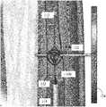
- FIG. 1shows an exemplary and non-limiting system for the intravascular placement of a medical device 100 .
- the system 100has a catheter apparatus component 110 including a guidewire 112 that is surrounded by a guidewire sheath 114 .
- the guidewire sheath 114is formed from a plastic, for example, a polymer or any other suitable, sterilizable material for a medical device.
- the guidewire sheath 114may be referred to as a micro catheter.
- the guidewire 112has a micro-anchor 116 on one end.
- the guidewire 112may be composed of stainless steel which may be monofilament or braided.
- the guidewire 112 and the micro-anchor 116may instead be composed of a shape-memory alloy, such as nitinol.
- the shape-memory alloymay be a copper-aluminum-nickel, or a nickel-titanium, and may be created by alloying zinc, copper, gold and iron.
- the guidewiremay be coated in Teflon, polyurethane, or another lubricious polymer.
- a small incisionis made in the skin at an entry site opening to a blood vessel, for example, the femoral artery.
- the catheter apparatus component 110including the guidewire sheath 114 and its enclosed guidewire 112 and micro-anchor 116 (in its collapsed position within the guidewire sheath 114 ), may then be guided into the blood vessel.
- the catheter apparatus component 110is flexible enough to travel through a tortuous path.
- a usertypically observes the travel of the catheter apparatus component 110 by x-ray or other technology as the catheter travels through the blood vessel.
- the micro-anchor 116remains inside of the guidewire sheath 114 .
- the catheter apparatus component 110is fed and guided until it reaches, for example, the superficial temporal artery in the side of a patient's face, or other appropriate artery.
- the guidewire 112may then be forced out of an end of the guidewire sheath 114 , causing the micro-anchor 116 to exit the guidewire sheath 114 and to deploy.
- the micro-anchor 116will then deploy to its original shape (i.e., expanded shape) within the superficial temporal artery, or other appropriate artery.
- the micro-anchor 116may be accessible regardless of the rotation of the micro-anchor 116 within the artery or other vessel.
- the size of the micro-anchoris selected for the artery or vessel.
- the diameter of the deployed or expanded micro-anchormay be any value or range of values between about 1.5 mm to 5 mm. It will be appreciated that the diameter may be less than 1.5 mm or more than 5 mm.
- the medical device 100also has an anchoring device 120 component.
- the devicemay include a pin portion 122 and a handle portion 124 .
- the handle portionmay take on various forms, such as, but not limited to, the embodiment shown in FIG. 1 , wherein the handle portion 124 is circular and is divided into three hollow sections by dividing member 126 .
- the dividing membermay be positioned to facilitate use of the anchoring device under a fluoroscope such that the handle portion 124 assists in aligning the pin portion 122 at the desired location. In this manner, the handle portion 124 provides means for aligning the pin portion 122 with the desired target location to intersect with the micro-anchor deployed in the vessel.
- the handle portion 124may be divided into four hollow sections.
- the pin portion 122is inserted substantially perpendicularly to the artery or other vessel in which the micro-anchor is deployed.
- the pin portion 122is guided to and through the micro-anchor 116 to stabilize the micro-anchor 116 , and, therefore the guidewire 112 .
- the stabilization of the guidewire 112increases the ease of subsequent medical treatments, such as angioplasty and stenting processes.
- Embodiments of the inventionare directed to a micro-anchor 116 that ensures better anchoring over prior art solutions.
- the micro-anchor 116is designed and configured to receive the pin portion 122 of the anchoring device 120 .
- the micro-anchor 116 described hereinmay provide greater control over the manipulation and positioning of a guidewire for the placement of medical devices.
- FIG. 2Ais an exemplary and non-limiting micro-anchor 116 A according to a first embodiment of the invention.
- the micro-anchor 116 Acomprises a first ring 200 and a second ring 204 , where the second ring is connected to the first ring at connection point 208 to essentially form a figure eight shaped micro-anchor.
- the rings 200 , 204are the same size. However, in other embodiments, the rings 200 , 204 may be different sizes. For example, ring 200 may be smaller than ring 204 ; in another example, ring 204 may be smaller than ring 200 .
- the first ring 200is oriented at a different angle than the second ring 204 .
- the second ring 204may be positioned at a 90 degree relative to the first ring 200 . It will be appreciated that the angle may be less than or more than 90 degrees.
- each two ringsform a figure-eight shape, and the plurality of rings forming a chain like connection of rings.
- Each of the different ringscan be oriented at a different angle to increase the likelihood that the pin portion 122 of the anchoring device 120 will engage with one of the rings.
- each ringcan be oriented at 45°, 90°, 135° and 180° respectively. It will be appreciated that other angles may be selected to provide for improved engagement of the pin portion 122 and the micro-anchor 116 A.
- ringsare shown to be in the shape of a circle, one of ordinary skill in the art will appreciate that other shapes may be used including, without limitation, ellipses and polygons (not shown).
- the micro-anchor 116 Ais connected to the guidewire 112 by connecting either or both the first ring 200 or the second ring 204 to the guidewire 112 .
- the first ring 200 and second ring 204are co-axial with one another and with the guidewire 112 .
- the first ring 200is co-planar with a longitudinal plane of the guidewire 112
- the second ring 204is not.
- the second ring 204may be coplanar with the longitudinal plan of the guidewire 112
- the first ring 200is not, or that neither of the rings 200 , 204 are coplanar with the longitudinal plane of the guidewire 112 .
- both rings 200 , 204 of the micro-anchor 116 Aare connected to the guidewire 112 at three different points: connection point 208 , connection point 212 and connection point 216 .
- Connection point 212is located on the first ring 200
- connection point 216is located on the second ring 204
- connection point 208is at the junction of the first ring 204 and second ring 208 .
- the connection points 212 and 216are located at opposite ends 220 , 224 of the micro-anchor 116 A.
- the connection point 212is closest to the guidewire sheath 114
- the connection point 216is farthest from the guidewire sheath 114 .
- connectionmay be done by molding, welding, pressing or the like as known to one of skill in the art. It will be appreciated that the connections may occur at other locations than those shown in FIG. 2 and that fewer or more than the number of connections illustrated may be used to attach the micro-anchor 116 A to the guidewire 112 .
- the guidewire 112has a short angulated tip 113 , the tip 113 being positioned outside the maximum scope of the deployed micro-anchor 116 A.
- the micro-anchor 116 Ais located a short distance from the tip.
- the micro-anchor 116 Amay be located any distance or range of distances between 2-15 mm from the distal tip. It will be appreciated that the distance may be less than 2 mm or more than 15 mm.
- the tip of the guidewire 112may be the micro-anchor 116 A itself (i.e., the guidewire does not include the angulated tip 113 ).
- the guidewire 112may be composed of stainless steel which may be monofilament or braided.
- the guidewire 112 and the micro-anchor 116 Amay instead be composed of a shape-memory alloy, such as nitinol.
- the shape-memory alloymay be a copper-aluminum-nickel, or a nickel-titanium, and may be created by alloying zinc, copper, gold and iron.
- the guidewire 112may be coated in Teflon, polyurethane, or another lubricious polymer. As it is made from a shape memory alloy exhibiting a temperature response at approximately body temperature, the micro-anchor 116 A will then deploy to its expanded shape within the superficial temporal artery, or other appropriate artery.
- the micro-anchor 116 A having the figure eight shapemay be formed by molding the micro-anchor 116 A out of a malleable material to have a shape similar to that shown in FIG. 2A .
- the rings 200 , 204may be formed first by bending a straight material, such as wire, into two separate rings, and then connecting the two rings together at the connection point by, for example, soldering, pressing, welding, etc.
- a wiremay be etched into the shape shown in FIG. 2A . It will be appreciated that a number of other techniques and processes for making the micro-anchor 116 A are contemplated, and the examples provided herein are not limiting.
- the micro-anchor 116 Ais delivered to a patient site as described above in a first, collapsed shape. At the patient site, the micro-anchor 116 A is deployed and expanded into its second, expanded shape, shown in FIG. 2A .
- the micro-anchor 116 Aexpands within the artery or vessel so that the micro-anchor 116 A engaged with the inner surface of the artery or vessel; alternatively, the micro-anchor 116 A expands within the artery or vessel so that the micro-anchor 116 A fills up a substantial portion but does not engage the vessel or artery.
- the micro-anchor 116 Amay be anchored at the patient site using the anchoring device 120 .
- the pin portion 122 of the anchoring device 120may be guided by the handle portion 124 to go through either one of the first ring 200 or the second ring 204 of the micro-anchor 116 A to anchor the guidewire 112 .
- FIG. 2Bshows a schematic diagram of the micro-anchor 116 A of FIG. 2A in a collapsed position prior to entering into the catheter 114 .
- FIG. 2Cshows a schematic diagram of the micro-anchor 116 A of FIG. 2A in a collapsed position partially placed into the catheter 114 .
- FIG. 3Ais an exemplary and non-limiting micro-anchor 116 B according to another embodiment of the invention.
- FIG. 3Bprovides an enlarged view of the micro-anchor 116 B.
- the micro-anchor 116 Bitself comprises a plurality of rings connect to one another. As shown in detail in FIG. 3B , the micro-anchor 116 B includes three rings 310 , 320 and 330 . Rings 310 , 320 and 330 each include a support 315 , 325 , and 335 , respectively.
- the support 315passes through an axis of the ring 310 and is connected to ring 310 at connection points 317 and 319
- support 325passes through an axis of the ring 320 and is connected to ring 320 at connection points 327 and 329
- support 325passes through ring 330 and is connected to ring 330 at 337 and 339 .
- Ring 310is connected to ring 320 at connection point 319
- ring 320is connected to ring 330 at connection point 329
- ring 330is connected to ring 310 at connection point 339 .
- the connectionmay be done by pressing, soldering, welding or the like.
- the micro-anchor 116 Bmay be formed by etching a wire.
- rings 310 , 320 , and 330are shown to be in the shape of a circle, one of ordinary skill in the art will appreciate that other shapes may be used including, without limitation, ellipses and polygons (not shown).
- the guidewire 112is split into a proximal portion and a distal portion. The guidewire 112 is further split at the proximal end of the distal portion to form first guidewire portion 340 and second guidewire portion 342 .
- First guidewire portion 340is connected to micro-anchor 116 B at connection point 344 .
- Second guidewire portion 342is connected to micro-anchor 116 B at connection point 346 . It will be appreciated that connections may occur at other places on the micro-anchor 116 B than those shown in FIGS. 3A and 3B .
- the micro-anchor 116 Bcan include guidewire connection elements that are similar to the guidewire portions 340 , 342 so that the micro-anchor 116 A has the shape shown in FIGS. 3A and 3B , and the guidewire connection elements are each connected to the guidewire at the same location.
- the rings 310 , 320 , 330are positioned such that when the micro-anchor 116 B is expanded, the rings 320 , 320 , 330 together form the outer surface of the micro-anchor 116 B.
- none of the supports 315 , 325 , 335are co-axial with the guidewire 112 or one another, and none of the supports 315 , 325 , 335 are parallel with another.
- the supports 315 , 325 , 335form a generally triangular shape when the micro-anchor is expanded. The positioning of the rings in this manner ensures that regardless of the angle respective of the pin 122 the micro-anchor 116 B is positioned, the pin 122 can successfully affix the micro-anchor 116 b within the vessel.
- the micro-anchor 116 Bis connected to a guidewire 112 on both ends of the micro-anchor 116 B.
- the guidewire 112has a short angulated tip 113 , the tip 113 being positioned outside the maximum scope of the deployed micro-anchor 116 B.
- the micro-anchor 116 Bmay instead be composed of a shape-memory alloy, such as nitinol.
- the shape-memory alloymay be a copper-aluminum-nickel, nickel-titanium or the like, and may be created by alloying, for example, zinc, copper, gold, iron, and the like.
- the micro-anchor 116 Bis made from a shape memory alloy exhibiting a temperature response at approximately body temperature, the micro-anchor 116 B will then deploy to its original shape within the superficial temporal artery, or other appropriate artery.
- the micro-anchor 116 Bis delivered to a patient site as described above in a first, collapsed shape. At the patient site, the micro-anchor 116 B is deployed and expanded into its second, expanded shape, shown in FIGS. 3A and 3B .
- the micro-anchor 116 Bexpands within the artery or vessel so that the micro-anchor 116 B engaged with the inner surface of the artery or vessel; alternatively, the micro-anchor 116 B expands within the artery or vessel so that the micro-anchor 116 B fills up a substantial portion but does not engage the vessel or artery.
- the micro-anchor 116 Bmay be anchored at the patient site using the anchoring device 120 .
- the pin portion 122 of the anchoring device 120may be guided by the handle portion 124 to go through any of the first ring 310 , second ring 320 and/or the space 360 between the third ring 330 and the guidewire 112 of the micro-anchor 116 A to anchor the guidewire 112 .
- the pin portion 122 of the anchoring device 120is shown passing through, and, therefore, engaging both the first ring 310 and the second ring 320 .
- FIG. 3Cshows a schematic diagram of the micro-anchor 116 B of FIG. 3A in a collapsed position prior to entering into the catheter 114 .
- FIG. 3Dshows a schematic diagram of the micro-anchor of 116 B of FIG. 3A in a collapsed position partially placed into the catheter 114 .
- FIG. 4is an exemplary and non-limiting micro-anchor 116 C according to another embodiment of the invention.
- the micro-anchor 116 Cincludes rings 410 and 420 , each having a support 415 , 425 .
- Support 415extends from connection point 417 to connection point 419 of the first ring 410 and support 425 extends from connection point 427 to connection point 429 of the second ring 420 .
- the rings 410 , 420are connected together only at connection point 408 , and the rings 410 , 420 are also only connected to the guidewire 112 at connection point 408 using known techniques.
- ring 410may connected to the guidewire at a first connection point and that ring 420 may be connected to the guidewire at a second, different location.
- the distance between the two connection pointsmay be selected to ensure a better change of engagement with one of the rings 410 , 420 .
- the rings 410 and 420each extend out at different angles relative to the longitudinal axis of the guidewire 112 . As shown in FIG. 4 , both rings 410 , 420 extend out at about a 30 degree angle relative to the longitudinal axis of the guidewire 112 . It will be appreciated that the angle may be any value or range of values between about 5 degrees and 90 degrees, and that the angle may also be less than 5 degrees or more than 90 degrees.
- rings 410 and 420While two rings 410 and 420 are shown, one of ordinary skill in the art would readily appreciate that any number of rings may be used without departing from the scope of the invention. Moreover, while elements 410 and 420 are shown as circles, one of ordinary skill in the art would readily appreciate that other shapes may be used, including without limitations ellipses and polygons.
- the micro-anchor 116 Cmay instead be composed of a shape-memory alloy, such as nitinol.
- the shape-memory alloymay be a copper-aluminum-nickel, nickel-titanium or the like, and may be created by alloying, for example, zinc, copper, gold, iron, and the like.
- the micro-anchor 116 Cis delivered to a patient site as described above in a first, collapsed shape. At the patient site, the micro-anchor 116 C is deployed and expanded into its second, expanded shape, shown in FIG. 4 .
- the micro-anchor 116 Cexpands within the artery or vessel so that the micro-anchor 116 C engaged with the inner surface of the artery or vessel; alternatively, the micro-anchor 116 C expands within the artery or vessel so that the micro-anchor 116 C fills up a substantial portion but does not engage the vessel or artery.
- the micro-anchor 116 Cmay be anchored at the patient site using the anchoring device 120 .
- the pin portion 122 of the anchoring device 120may be guided by the handle portion 124 to go through either of the first ring 410 and/or the second ring 420 .
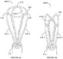
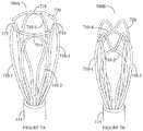
- FIGS. 5A, 6A and 7Adepict a two-petal micro-anchor 500 A, a three-petal micro-anchor 600 A and a four-petal micro-anchor 700 A, respectively, each shown in their respective open position.
- the guidewire 112 placed within the sheath 114ends with a plurality of petals 510 , 610 or 710 which form the micro-anchors 500 A, 600 A and 700 A respectively.
- the petalshave a generally narrow base near the guidewire sheath 114 , and, as the petals extend further away from the guidewire sheath 114 , the shape gradually expands into a larger, bulbous section.
- the petalsmay be formed by forming a wire into the shape of the petal and connecting them to the end of the guidewire using known methods. Alternatively, the petals may be formed by etching the end of the guidewire 112 to have the shape shown in FIGS. 5A, 6A and 7A .
- the micro-anchor 500 Aincludes two petals 510 - 1 and 510 - 2 and a ring 520 .
- the top tip of the petal 510 - 1is connected to ring 520 at a first point of contact 514 and the top tip of the petal 510 - 2 is connected to ring 520 at a second point of contact 518 .
- the connectionmay be done by pressing, soldering, welding or the like.
- the micro-anchor 600 Aincludes three petals 610 - 1 , 610 - 2 and 610 - 3 and a ring 620 .
- the top tip of the petal 610 - 1is connected to ring 620 at a first point of contact 614
- the top tip of the petal 510 - 2is connected to ring 620 at a second point of contact 618
- the top tip of the petal 510 - 3is connected to ring 620 at a third point of contact 612 .
- the connectionmay be done by pressing, soldering, welding or the like.
- the micro-anchor 500 Cincludes four petals 710 - 1 , 710 - 2 , 710 - 3 and 710 - 4 .
- the top tip of the petal 710 - 1is connected to ring 720 at a first point of contact 712
- the top tip of the petal 710 - 2is connected to ring 720 at a second point of contact 714
- the top tip of the petal 710 - 3is connected to ring 720 at a third point of contact 716
- the top tip of petal 710 - 4is connected to ring 720 at a fourth point of contact 718 .
- the connectionmay be done by pressing, soldering, welding or the like.
- FIGS. 5A, 6A and 7Aare merely exemplary and additional petals or differently-shaped petals may be implemented without departing from the scope of the invention.
- the micro-anchors 500 , 600 and 700are positioned at the end of the guidewire 112 (i.e., the micro-anchor 500 , 600 or 700 is the tip of the guidewire 112 ).
- the operation of the micro-anchors 500 , 600 or 700is similar to the operation discussed herein in that it is while within the sheath 114 is compressed to fit therein, and, when pushed outside of the sheath 114 , it resumes its open position, and may be used for anchoring purposes as described herein.
- the collapsed positions of the micro-anchors 500 , 600 , and 700are shown in FIGS. 5B, 6B and 7B respectively, as collapsed micro-anchors 500 B, 600 B and 700 B respectively.
- the micro-anchors 500 , 600 or 700may be composed of a shape-memory alloy, such as nitinol.
- the shape-memory alloymay be a copper-aluminum-nickel, or a nickel-titanium, and may be created by alloying zinc, copper, gold and iron.
- the micro-anchors 500 , 600 or 700will then deploy to their original shape within the superficial temporal artery, or other appropriate artery.
- the guidewire 112may extend through the micro-anchors 500 , 600 or 700 and may be further equipped with an angulated tip, such as angulated tip 113 described herein.
- the micro-anchors 500 , 600 or 700would be connected to the guidewire 112 in a manner similar to that previously described herein with reference to FIGS. 2-4 .
- the micro-anchor 500 , 600 or 700are delivered to a patient site as described above in a first, collapsed shape ( 500 B, 600 B or 700 B as the case may be).
- the micro-anchor 500 , 600 or 700is deployed and expanded into its second, expanded shape, shown in FIG. 5A, 6A or 7A , shown as 500 B, 600 B or 700 B respectively.
- micro-anchors 500 , 600 or 700expand within the artery or vessel so that the micro-anchors 500 , 600 or 700 engage with the inner surface of the artery or vessel; alternatively, the micro-anchors 500 , 600 or 700 expand within the artery or vessel so that the micro-anchors 500 , 600 or 700 fill up a substantial portion but do not engage the vessel or artery.
- the micro-anchors 500 , 600 or 700may be anchored at the patient site using the anchoring device 120 .
- the pin portion 122 of the anchoring device 120may be guided by the handle portion 124 to go through any one or combination of the petals 510 , 610 or 710 of the micro-anchors 500 , 600 or 700 respectively or spaces between petals 510 , 610 or 710 and the ring 520 to anchor the guidewire 112 .
- micro-anchor 800may be connected to a guidewire (not shown) that guides the micro-anchor 800 within a sheath 114 .
- the micro-anchoris shown in its opened position.
- the guidewiremay extend beyond the micro-anchor 800 and further have a bent tip as shown with respect to other embodiments detailed herein and which is not repeated yet once again.
- An anchoring pinmay be used to anchor the micro-anchor 800 in ways explained elsewhere herein.
- the micro-anchorincludes a plurality of inner petals 804 and a plurality of outer petals 808 .
- the micro-anchorincludes five inner petals 804 and five outer petals 808 ; however, it will be appreciated that the number of inner petals and the number of outer petals may be less than or more than five and that the number of inner petals and the number of outer petals need not be the same.
- each one of the outer petals 808is connected to two adjacent inner petals 804 .
- the petals 804 , 808may be connected as shown in FIG. 8 by, for example, pressing, soldering, welding or the like.
- the micro-anchor 800may be composed of a shape-memory alloy, such as nitinol.
- the shape-memory alloymay be a copper-aluminum-nickel, or a nickel-titanium, and may be created by alloying zinc, copper, gold and iron. As it is made from a shape memory alloy exhibiting a temperature response at approximately body temperature, the micro-anchors 800 will then deploy to their original shape within the superficial temporal artery, or other appropriate artery.
- the micro-anchor 800is delivered to a patient site as described above in a first, collapsed shape (not shown). At the patient site, the micro-anchor 800 is deployed and expanded into its second, expanded shape, shown in FIG. 8 .
- the micro-anchor 800expands within the artery or vessel so that the micro-anchor 800 engages with the inner surface of the artery or vessel; alternatively, the micro-anchor 800 expands within the artery or vessel so that the micro-anchor 800 fills up a substantial portion but do not engage the vessel or artery.
- the micro-anchor 800may be anchored at the patient site using the anchoring device 120 .
- the pin portion 122 of the anchoring device 120may be guided by the handle portion 124 to go through any one or combination of the inner petals 804 or outer petals 808 of the micro-anchor 800 respectively.
- FIGS. 9A and 9Bthere is shown another exemplary and non-limiting micro-anchor 900 in accordance with yet another embodiment of the invention.
- the micro-anchor 900is shown outside of a sheath 114 in FIG. 9A and within a sheath 114 in FIG. 9B .
- the micro-anchor 900differs from its predecessor micro-anchors described herein in that it has only a single mode, that is, the micro-anchor 900 does not expand or collapse.
- a guidewiremay extend beyond the micro-anchor 900 and further have a bent tip as shown with respect to other embodiments detailed herein and which is not repeated yet once again.
- the micro-anchor 900includes a proximal end 904 and a distal end 908 .
- the proximal end 904includes a number of openings 912 defined by structure 916
- the distal end 908includes a structure 920 connected to the structure 916 that defines a number of additional openings 924 .
- the additional openings 924are concentric with the openings 912 , but also include additional opening portions 928 that extend beyond the length of the openings 912 .
- An anchoring pinmay be used to anchor the micro-anchor 900 in ways explained elsewhere herein.
- the use of micro-anchor 900is of particular value in cases where it is not desirable or otherwise possible to use an expanding micro-anchor of the micro-anchors described herein which have expanding capabilities.
- the micro-anchor 900may be composed of a shape-memory alloy, such as nitinol.
- the shape-memory alloymay be a copper-aluminum-nickel, or a nickel-titanium, and may be created by alloying zinc, copper, gold and iron.
- the micro-anchors 900will then deploy to their original shape within the superficial temporal artery, or other appropriate artery.
- other metals and/or alloysmay be used, including but not limited to non-shape memory alloy.
- the presently disclosed systemmay be used to access and navigate a type III aortic arch.
- a first cathetersuch as a Simmons catheter or other catheter having a reverse curve or hook configuration, may be used to gain access to the ascending aorta and carotid artery and to secure the catheter in place.
- a micro catheter or guidewire sheathmay then be advanced through the first catheter and advanced into the carotid artery.
- a guidewire having a micro-anchor of any one of the types disclosed hereinis disposed within the micro catheter.
- the micro-anchorhas a tip that may be angled to facilitate selection of the external carotid artery and navigate the micro catheter to the desired location.
- the micro-anchormay be extended from the micro catheter allowing the micro-anchor to expand and be secured in the vessel with an anchoring device as discussed below.
- a conventional guidewiremay be used to advance the micro catheter to the desired location.
- the conventional guidewiremay be removed, and the guidewire having micro-anchor may be inserted and advanced through the catheter until the micro-anchor extends from the micro catheter and expands to be secured in the vessel.
- a carotid stenting or other proceduremay be performed. In this manner the system may provide a stabilized platform for intervention in tortuous arteries of the head, neck or other extremities.
- the intravascular anchor described hereinfacilitates the stenting of the internal carotid artery or common carotid artery.
- thisshould not be viewed as limiting the scope of the invention.
- the disclosed inventions as well as embodiments thereofmay apply to the stenting of the subclavian artery by anchoring in the radial artery. It may be further used, without limitation, for stenting in the lower extremity in situations of acute angulation or tortuosity at the aorto iliac bifurcation.
- a practitionercould access the common femoral artery using a retrograde contralateral approach and intervene in the opposite lower extremity by anchoring a device implemented according to the principles of the invention anywhere in the lower extremity.
Landscapes
- Health & Medical Sciences (AREA)
- Life Sciences & Earth Sciences (AREA)
- Engineering & Computer Science (AREA)
- Biomedical Technology (AREA)
- Veterinary Medicine (AREA)
- Animal Behavior & Ethology (AREA)
- Public Health (AREA)
- Heart & Thoracic Surgery (AREA)
- General Health & Medical Sciences (AREA)
- Hematology (AREA)
- Anesthesiology (AREA)
- Pulmonology (AREA)
- Biophysics (AREA)
- Cardiology (AREA)
- Oral & Maxillofacial Surgery (AREA)
- Transplantation (AREA)
- Vascular Medicine (AREA)
- Media Introduction/Drainage Providing Device (AREA)
- Surgical Instruments (AREA)
Abstract
Description
Claims (17)
Priority Applications (1)
| Application Number | Priority Date | Filing Date | Title |
|---|---|---|---|
| US14/638,438US10588766B2 (en) | 2012-11-21 | 2015-03-04 | Steerable intravascular anchor and method of operation |
Applications Claiming Priority (3)
| Application Number | Priority Date | Filing Date | Title |
|---|---|---|---|
| US201261728862P | 2012-11-21 | 2012-11-21 | |
| PCT/US2013/071271WO2014081947A1 (en) | 2012-11-21 | 2013-11-21 | System for the intravascular placement of a medical device |
| US14/638,438US10588766B2 (en) | 2012-11-21 | 2015-03-04 | Steerable intravascular anchor and method of operation |
Related Parent Applications (1)
| Application Number | Title | Priority Date | Filing Date |
|---|---|---|---|
| PCT/US2013/071271Continuation-In-PartWO2014081947A1 (en) | 2012-11-21 | 2013-11-21 | System for the intravascular placement of a medical device |
Publications (2)
| Publication Number | Publication Date |
|---|---|
| US20150174377A1 US20150174377A1 (en) | 2015-06-25 |
| US10588766B2true US10588766B2 (en) | 2020-03-17 |
Family
ID=50776559
Family Applications (2)
| Application Number | Title | Priority Date | Filing Date |
|---|---|---|---|
| US14/429,759Active2035-03-02US10639179B2 (en) | 2012-11-21 | 2013-11-21 | System for the intravascular placement of a medical device |
| US14/638,438Active2035-10-09US10588766B2 (en) | 2012-11-21 | 2015-03-04 | Steerable intravascular anchor and method of operation |
Family Applications Before (1)
| Application Number | Title | Priority Date | Filing Date |
|---|---|---|---|
| US14/429,759Active2035-03-02US10639179B2 (en) | 2012-11-21 | 2013-11-21 | System for the intravascular placement of a medical device |
Country Status (2)
| Country | Link |
|---|---|
| US (2) | US10639179B2 (en) |
| WO (1) | WO2014081947A1 (en) |
Families Citing this family (12)
| Publication number | Priority date | Publication date | Assignee | Title |
|---|---|---|---|---|
| US10213187B1 (en) | 2012-01-25 | 2019-02-26 | Mubin I. Syed | Method and apparatus for percutaneous superficial temporal artery access for carotid artery stenting |
| WO2014081947A1 (en) | 2012-11-21 | 2014-05-30 | Syed Mubin I | System for the intravascular placement of a medical device |
| US9636244B2 (en) | 2015-04-09 | 2017-05-02 | Mubin I. Syed | Apparatus and method for proximal to distal stent deployment |
| US11020256B2 (en) | 2015-10-30 | 2021-06-01 | Ram Medical Innovations, Inc. | Bifurcated “Y” anchor support for coronary interventions |
| US10327929B2 (en) | 2015-10-30 | 2019-06-25 | Ram Medical Innovations, Llc | Apparatus and method for stabilization of procedural catheter in tortuous vessels |
| US10492936B2 (en) | 2015-10-30 | 2019-12-03 | Ram Medical Innovations, Llc | Apparatus and method for improved access of procedural catheter in tortuous vessels |
| US10779976B2 (en)* | 2015-10-30 | 2020-09-22 | Ram Medical Innovations, Llc | Apparatus and method for stabilization of procedural catheter in tortuous vessels |
| US9980838B2 (en)* | 2015-10-30 | 2018-05-29 | Ram Medical Innovations Llc | Apparatus and method for a bifurcated catheter for use in hostile aortic arches |
| US10053693B2 (en) | 2016-01-19 | 2018-08-21 | Mubin I. Syed | Method for controlling obesity using minimally invasive means |
| US10173031B2 (en) | 2016-06-20 | 2019-01-08 | Mubin I. Syed | Interchangeable flush/selective catheter |
| WO2018164766A1 (en)* | 2017-03-06 | 2018-09-13 | Ram Medical Innovations Llc | Apparatus and method for improved access of procedural catheter in tortuous vessels |
| US11007075B2 (en) | 2018-02-18 | 2021-05-18 | Ram Medical Innovations, Inc. | Vascular access devices and methods for lower limb interventions |
Citations (176)
| Publication number | Priority date | Publication date | Assignee | Title |
|---|---|---|---|---|
| US4243040A (en) | 1979-09-17 | 1981-01-06 | Beecher William H | Extracting device for removing objects from human body passages |
| US4790331A (en) | 1986-12-02 | 1988-12-13 | Sherwood Medical Company | Method for placement of catheter in a blood vessel |
| US5098707A (en) | 1989-07-31 | 1992-03-24 | Merck & Co., Inc. | Imidazole compounds and their use as transglutaminase inhibitors |
| US5293772A (en) | 1992-01-17 | 1994-03-15 | Center For Innovative Technology | Instrumentation and method for evaluating platelet performance during clotting and dissolution of blood clots and for evaluating erythrocyte flexibility |
| US5344426A (en) | 1990-04-25 | 1994-09-06 | Advanced Cardiovascular Systems, Inc. | Method and system for stent delivery |
| US5419777A (en) | 1994-03-10 | 1995-05-30 | Bavaria Medizin Technologie Gmbh | Catheter for injecting a fluid or medicine |
| US5571135A (en) | 1993-10-22 | 1996-11-05 | Scimed Life Systems Inc. | Stent delivery apparatus and method |
| WO1996036269A2 (en) | 1995-05-09 | 1996-11-21 | Edoga John K | Methods and apparatus for treating abdominal aortic aneurysms |
| US5651366A (en) | 1994-09-19 | 1997-07-29 | Board Of Trustees Of The Leland Stanford Junior University | Forward viewing ultrasonic imaging catheter |
| US5662703A (en) | 1995-04-14 | 1997-09-02 | Schneider (Usa) Inc. | Rolling membrane stent delivery device |
| US5669924A (en) | 1995-10-26 | 1997-09-23 | Shaknovich; Alexander | Y-shuttle stent assembly for bifurcating vessels and method of using the same |
| US5690644A (en) | 1992-12-30 | 1997-11-25 | Schneider (Usa) Inc. | Apparatus for deploying body implantable stent |
| US5718702A (en) | 1992-08-12 | 1998-02-17 | Somnus Medical Technologies, Inc. | Uvula, tonsil, adenoid and sinus tissue treatment device and method |
| US5720735A (en) | 1997-02-12 | 1998-02-24 | Dorros; Gerald | Bifurcated endovascular catheter |
| US5766192A (en) | 1995-10-20 | 1998-06-16 | Zacca; Nadim M. | Atherectomy, angioplasty and stent method and apparatus |
| US5807330A (en) | 1996-12-16 | 1998-09-15 | University Of Southern California | Angioplasty catheter |
| US5813976A (en)* | 1996-04-02 | 1998-09-29 | Filipi; Charles J. | Stabilizing instrumentation for the performing of endoscopic surgical procedures |
| US5957901A (en) | 1997-10-14 | 1999-09-28 | Merit Medical Systems, Inc. | Catheter with improved spray pattern for pharmaco-mechanical thrombolysis therapy |
| US5997563A (en) | 1998-09-28 | 1999-12-07 | Medtronic, Inc. | Implantable stent having variable diameter |
| US6027462A (en) | 1998-07-30 | 2000-02-22 | Medtronic, Inc. | Method and apparatus for deflecting a screw-in-lead |
| US6059813A (en) | 1998-11-06 | 2000-05-09 | Scimed Life Systems, Inc. | Rolling membrane stent delivery system |
| US6070589A (en) | 1997-08-01 | 2000-06-06 | Teramed, Inc. | Methods for deploying bypass graft stents |
| US6152141A (en) | 1994-07-28 | 2000-11-28 | Heartport, Inc. | Method for delivery of therapeutic agents to the heart |
| US6245573B1 (en) | 1998-02-12 | 2001-06-12 | University Of Medicine And Dentistry Of New Jersey | Rapid assessment of the coagulant activity of blood |
| US6245017B1 (en) | 1998-10-30 | 2001-06-12 | Kabushiki Kaisha Toshiba | 3D ultrasonic diagnostic apparatus |
| US20010003985A1 (en) | 1997-03-06 | 2001-06-21 | Lafontaine Daniel M. | System and method for percutaneous coronary artery bypass |
| US20010049534A1 (en) | 1998-12-16 | 2001-12-06 | Fumedica Intertrade Ag | Device for inserting an aortic endoprosthesis |
| US20020077691A1 (en) | 2000-12-18 | 2002-06-20 | Advanced Cardiovascular Systems, Inc. | Ostial stent and method for deploying same |
| US6428567B2 (en) | 1997-08-13 | 2002-08-06 | Advanced Cardiovascular Systems, Inc. | Stent and catheter assembly and method for treating bifurcations |
| US20020123698A1 (en) | 1996-10-11 | 2002-09-05 | Transvascular, Inc. | Systems and methods for directing and snaring guidewires |
| US6450964B1 (en) | 2000-09-05 | 2002-09-17 | Advanced Cardiovascular Systems, Inc. | Imaging apparatus and method |
| US6464665B1 (en)* | 2000-07-05 | 2002-10-15 | Richard R. Heuser | Catheter apparatus and method for arterializing a vein |
| US20020156518A1 (en) | 2001-03-23 | 2002-10-24 | Hassan Tehrani | Branched aortic arch stent graft and method of deployment |
| US20020165535A1 (en) | 2000-05-16 | 2002-11-07 | Lesh Michael D. | Deflectable tip catheter with guidewire tracking mechanism |
| US6494875B1 (en) | 1998-08-24 | 2002-12-17 | Advanced Cardiovascular Systems, Inc. | Bifurcated catheter assembly |
| US6544278B1 (en) | 1998-11-06 | 2003-04-08 | Scimed Life Systems, Inc. | Rolling membrane stent delivery system |
| US20030088187A1 (en) | 2001-07-12 | 2003-05-08 | Vahid Saadat | Device for sensing parameters of a hollow body organ |
| US20030216721A1 (en) | 2002-01-15 | 2003-11-20 | The Regents Of The University Of Calfornia | System and method providing directional ultrasound therapy to skeletal joints |
| US20030229282A1 (en) | 1997-11-24 | 2003-12-11 | Burdette Everette C. | Real time brachytherapy spatial registration and visualization system |
| US6663613B1 (en) | 2000-01-25 | 2003-12-16 | Bacchus Vascular, Inc. | System and methods for clot dissolution |
| US20040073190A1 (en) | 2002-07-02 | 2004-04-15 | The Foundry Inc. | Methods and devices for treating aneurysms |
| US20040087995A1 (en) | 2002-08-22 | 2004-05-06 | Copa Vincent G. | Anastomosis device and related methods |
| US20040138734A1 (en) | 2001-04-11 | 2004-07-15 | Trivascular, Inc. | Delivery system and method for bifurcated graft |
| US6764505B1 (en) | 2001-04-12 | 2004-07-20 | Advanced Cardiovascular Systems, Inc. | Variable surface area stent |
| US20040147837A1 (en) | 2001-02-06 | 2004-07-29 | Macaulay Patrick E | Methods and apparatus for guided transluminal interventions using vessel wall penetrating catheters and other apparatus |
| US20040167463A1 (en) | 2003-02-21 | 2004-08-26 | Zawacki John A. | Multi-lumen catheter with separate distal tips |
| WO2004089249A1 (en) | 2003-04-03 | 2004-10-21 | William A. Cook Australia Pty. Ltd. | Branch stent graft deployment and method |
| US6808520B1 (en) | 1991-12-13 | 2004-10-26 | Endovascular Technologies, Inc. | Dual valve, flexible expandable sheath and method |
| US6837881B1 (en) | 2001-02-23 | 2005-01-04 | Coaxia, Inc. | Devices and methods for preventing distal embolization using flow reversal by partial occlusion of the brachiocephalic artery |
| US20050043779A1 (en) | 1999-12-10 | 2005-02-24 | Wilson W. Stan | Bifurcated stent delivery system having retractable sheath |
| US20050085841A1 (en) | 2003-04-24 | 2005-04-21 | Eversull Christian S. | Expandable sheath for delivering instruments and agents into a body lumen and methods for use |
| US20050101968A1 (en)* | 2003-11-12 | 2005-05-12 | Dadourian Daniel G. | Ostial locator device and methods for transluminal interventions |
| US20050113862A1 (en) | 2003-10-27 | 2005-05-26 | Besselink Petrus A. | Self-activating endoluminal device |
| US6929633B2 (en) | 2000-01-25 | 2005-08-16 | Bacchus Vascular, Inc. | Apparatus and methods for clot dissolution |
| US6932829B2 (en) | 2002-06-24 | 2005-08-23 | Cordis Corporation | Centering catheter |
| US20050222488A1 (en) | 2003-10-01 | 2005-10-06 | Ample Medical, Inc. | Devices, systems, and methods for reshaping a heart valve annulus |
| US20050234499A1 (en) | 2004-04-19 | 2005-10-20 | Scimed Life Systems, Inc. | Multi-lumen balloon catheter including manifold |
| US20050251160A1 (en) | 2004-05-07 | 2005-11-10 | Usgi Medical Inc. | Apparatus for manipulating and securing tissue |
| US20060025752A1 (en) | 2004-07-28 | 2006-02-02 | Broaddus William C | Coaxial catheter systems for transference of medium |
| US20060025844A1 (en) | 2004-07-28 | 2006-02-02 | Majercak David C | Reduced deployment force delivery device |
| US20060030923A1 (en) | 2004-08-06 | 2006-02-09 | Gunderson Richard C | Stent delivery system |
| US20060036218A1 (en) | 2002-09-20 | 2006-02-16 | Flowmedica, Inc. | Method and apparatus for selective material delivery via an intra-renal catheter |
| US20060155363A1 (en) | 2005-01-10 | 2006-07-13 | Laduca Robert | Apparatus and method for deploying an implantable device within the body |
| US20060200221A1 (en) | 2005-03-03 | 2006-09-07 | Andrzej Malewicz | Rolling membrane with hydraulic recapture means for self expanding stent |
| US20060257389A1 (en) | 2005-04-25 | 2006-11-16 | Jacob Binford | Diagnosis of blood clots using fibrin-binding proteins bound with contrast agents |
| US20060259063A1 (en)* | 2005-04-25 | 2006-11-16 | Bates Brian L | Wire guides having distal anchoring devices |
| US20060270900A1 (en) | 2005-05-26 | 2006-11-30 | Chin Albert K | Apparatus and methods for performing ablation |
| US20070016062A1 (en) | 2005-05-04 | 2007-01-18 | Byong-Ho Park | Multiple transducers for intravascular ultrasound imaging |
| US20070016019A1 (en) | 2003-09-29 | 2007-01-18 | Koninklijke Phillips Electronics N.V. | Ultrasonic cardiac volume quantification |
| US20070038061A1 (en) | 2005-06-24 | 2007-02-15 | Volcano Corporation | Three dimensional co-registration for intravascular diagnosis and therapy |
| US20070038293A1 (en) | 1999-04-09 | 2007-02-15 | St Goar Frederick G | Device and methods for endoscopic annuloplasty |
| US20070049867A1 (en) | 2005-08-05 | 2007-03-01 | Shindelman Larry E | System for treating chronic total occlusion caused by lower extremity arterial disease |
| US20070083215A1 (en) | 2005-10-07 | 2007-04-12 | Hamer Rochelle M | Conduit for interventional procedures |
| US20070118151A1 (en) | 2005-11-21 | 2007-05-24 | The Brigham And Women's Hospital, Inc. | Percutaneous cardiac valve repair with adjustable artificial chordae |
| US20070129719A1 (en) | 2005-05-26 | 2007-06-07 | Amar Kendale | Apparatus and methods for performing minimally-invasive surgical procedures |
| US7235083B1 (en) | 2003-09-10 | 2007-06-26 | Endovascular Technologies, Inc. | Methods and devices for aiding in situ assembly of repair devices |
| US20080039746A1 (en) | 2006-05-25 | 2008-02-14 | Medtronic, Inc. | Methods of using high intensity focused ultrasound to form an ablated tissue area containing a plurality of lesions |
| US20080114239A1 (en) | 2006-11-10 | 2008-05-15 | Penrith Corporation | Transducer array imaging system |
| US7393358B2 (en) | 2004-08-17 | 2008-07-01 | Boston Scientific Scimed, Inc. | Stent delivery system |
| US20080194993A1 (en)* | 2006-11-15 | 2008-08-14 | Mclaren Douglas E | Multi-dimensional loop tip elongated medical structures |
| US20080208309A1 (en) | 2007-02-22 | 2008-08-28 | Mohsin Saeed | Apparatus and method for implantation of a bifurcated endovascular prosthesis |
| US20080281398A1 (en) | 2007-05-07 | 2008-11-13 | Koss Alexander K | Stent delivery and deployment system |
| US20090005679A1 (en) | 2007-06-30 | 2009-01-01 | Ep Medsystems, Inc. | Ultrasound Image Processing To Render Three-Dimensional Images From Two-Dimensional Images |
| US20090018526A1 (en)* | 2005-08-25 | 2009-01-15 | John Melmouth Power | Devices and Methods for Perfusing an Organ |
| US20090036780A1 (en) | 2007-08-03 | 2009-02-05 | Innoscion, Llc | Wired and Wireless Remotely Controlled Ultrasonic Transducer and Imaging Apparatus |
| US20090093791A1 (en) | 1999-09-17 | 2009-04-09 | Heuser Richard R | Devices and methods for treating chronic total occlusion |
| US20090132019A1 (en) | 2007-11-15 | 2009-05-21 | Medtronic Vascular, Inc. | Bifurcate Stent Delivery Catheter |
| US20090171293A1 (en) | 2007-12-28 | 2009-07-02 | Wilson-Cook Medical Inc. | Self expanding wire guide |
| US20090177035A1 (en) | 2008-01-03 | 2009-07-09 | Chin Albert K | Endoscope instruments systems and methods for closed chest epicardial ablation |
| US20090240253A1 (en) | 2007-12-07 | 2009-09-24 | Wright Medical Technology, Inc. | Pin Centering Guide with Goniometer |
| US20090254116A1 (en) | 2008-04-03 | 2009-10-08 | Gardia Medical Ltd. | Retrieval catheter and methods of retrieving deployed medical devices |
| US20090270975A1 (en) | 1999-10-12 | 2009-10-29 | Gifford Iii Hanson S | Methods and devices for protecting a passageway in a body when advancing devices through the passageway |
| US20090319017A1 (en) | 2004-05-25 | 2009-12-24 | Chestnut Medical Technologies, Inc. | Vascular stenting for aneurysms |
| US20100016943A1 (en) | 2001-12-20 | 2010-01-21 | Trivascular2, Inc. | Method of delivering advanced endovascular graft |
| US7651520B2 (en) | 2006-05-30 | 2010-01-26 | Ostial Solutions, Llc | Means and method for the accurate placement of a stent at the ostium of an artery |
| US20100024818A1 (en) | 2008-07-29 | 2010-02-04 | Alex Stenzler | Closed suction catheter adapter with flush arrangement |
| US20100030256A1 (en) | 1997-11-12 | 2010-02-04 | Genesis Technologies Llc | Medical Devices and Methods |
| US20100030165A1 (en) | 2008-07-30 | 2010-02-04 | Terumo Kabushiki Kaisha | Catheter assembly |
| US20100069852A1 (en) | 2008-09-17 | 2010-03-18 | Gregory Scott Kelley | Delivery system for deployment of medical devices |
| US7740791B2 (en) | 2006-06-30 | 2010-06-22 | Advanced Cardiovascular Systems, Inc. | Method of fabricating a stent with features by blow molding |
| US20100168583A1 (en) | 2006-11-03 | 2010-07-01 | Research Triangle Institute | Enhanced ultrasound imaging probes using flexure mode piezoelectric transducers |
| US7758624B2 (en) | 2000-11-13 | 2010-07-20 | C. R. Bard, Inc. | Implant delivery device |
| US20100185161A1 (en) | 2002-09-30 | 2010-07-22 | Relievant Medsystems, Inc. | Systems and methods for navigating an instrument through bone |
| US20100185231A1 (en) | 2009-01-16 | 2010-07-22 | Lashinski Randall T | Intravascular Blood Filter |
| US7766961B2 (en) | 2003-06-05 | 2010-08-03 | Angio Dynamics, Inc. | Systems and methods for performing bi-lateral interventions or diagnosis in branched body lumens |
| US20100204708A1 (en) | 2010-02-23 | 2010-08-12 | Sanjiv Sharma | Carotid guiding catheter (sheath) for carotid percutaneous intervention/stenting with internal fixation device to prevent migration of the Carotid guiding catheter (sheath) |
| US20100268067A1 (en) | 2009-02-17 | 2010-10-21 | Inneroptic Technology Inc. | Systems, methods, apparatuses, and computer-readable media for image guided surgery |
| US20100272740A1 (en) | 2007-10-17 | 2010-10-28 | Alexey Vertegel | Micro- and nanoscale devices for delivery of active fibronolytic agents |
| US7828832B2 (en) | 2005-04-18 | 2010-11-09 | Medtronic Vascular, Inc. | Intravascular deployment device with improved deployment capability |
| WO2010129193A1 (en) | 2009-05-08 | 2010-11-11 | Koninklijke Philips Electronics, N.V. | Ultrasonic planning and guidance of implantable medical devices |
| US20100298922A1 (en) | 2009-05-22 | 2010-11-25 | Ulbrich Precision Metals Limited | Angioplasty Assembly |
| US7842026B2 (en) | 2005-12-29 | 2010-11-30 | Nmt Medical, Inc. | Syringe activated-valve for flushing a catheter and methods thereof |
| US20110009943A1 (en) | 2009-07-09 | 2011-01-13 | Paul Ram H | Delivery system with medical device release by evertable sleeve |
| WO2011011539A1 (en) | 2009-07-21 | 2011-01-27 | University Of Virginia Patent Foundation | Systems and methods for ultrasound imaging and insonation of microbubbles |
| US20110034987A1 (en) | 2009-08-04 | 2011-02-10 | Kennedy Kenneth C | Roll sleeve mechanism for proximal release stent |
| US20110071394A1 (en) | 2009-09-23 | 2011-03-24 | Fedinec James J | Central venous catheter kit with line gripping and needle localizing devices |
| US20110082533A1 (en) | 1996-11-04 | 2011-04-07 | Boston Scientific Scimed, Inc. | Extendible Stent Apparatus |
| US20110213459A1 (en) | 2010-02-26 | 2011-09-01 | Garrison Michi E | Systems and methods for transcatheter aortic valve treatment |
| WO2011106502A2 (en) | 2010-02-25 | 2011-09-01 | Mayo Foundation For Medical Education And Research | Delivering drugs to desired locations within a mammal |
| US20110224773A1 (en) | 1999-10-12 | 2011-09-15 | Gifford Hanson S | Methods and devices for protecting a passageway in a body when advancing devices through the passageway |
| WO2011137336A1 (en) | 2010-04-30 | 2011-11-03 | President And Fellows Of Harvard College | Motion compensating catheter device |
| US20110270375A1 (en) | 2003-10-14 | 2011-11-03 | Cook Medical Technologies Llc | Introducer for an iliac side branch device |
| US20120016343A1 (en) | 2010-07-19 | 2012-01-19 | Sukhjit Gill | Guiding catheter stabilization system |
| US20120020942A1 (en) | 2005-12-22 | 2012-01-26 | Organobalance, GMBH | Novel Lactobacillus Strains And Their Use Against Helicobacter Pylori |
| US20120029478A1 (en) | 2009-04-14 | 2012-02-02 | Terumo Kabushiki Kaisha | Guide wire for medical treatment |
| US20120035590A1 (en) | 2006-02-03 | 2012-02-09 | Pacesetter, Inc. | System and method for manipulating insertion pathways for accessing target sites |
| US20120034205A1 (en) | 2010-07-08 | 2012-02-09 | Alkon Daniel L | Pkc activators and anticoagulant in regimen for treating stroke |
| WO2012030101A2 (en) | 2010-09-03 | 2012-03-08 | (주)태웅메디칼 | Catheter for stent operation use |
| US8202309B2 (en) | 2005-05-19 | 2012-06-19 | Laboratoires Perouse | Kit for inserting a cavity-treatment element and method for preparing an associated treatment element |
| US20120169712A1 (en) | 2010-12-30 | 2012-07-05 | Hill Anthony D | Display of medical device position information in a volumetric rendering |
| US20120209375A1 (en) | 2011-02-11 | 2012-08-16 | Gilbert Madrid | Stability device for use with percutaneous delivery systems |
| US20120289945A1 (en) | 2011-05-13 | 2012-11-15 | Merit Medical Systems, Inc. | Releasably attached snare loop retrieval device and method of using the same |
| US8343181B2 (en) | 2007-03-01 | 2013-01-01 | Medtronic Vascular, Inc. | Method and apparatus for treating stenoses at bifurcated regions |
| US20130053792A1 (en) | 2011-08-24 | 2013-02-28 | Ablative Solutions, Inc. | Expandable catheter system for vessel wall injection and muscle and nerve fiber ablation |
| US8419767B2 (en) | 2010-05-04 | 2013-04-16 | Mustafa H. Al-Qbandi | Steerable atrial septal occluder implantation device with flexible neck |
| US20130296773A1 (en) | 2009-12-04 | 2013-11-07 | Cook Medical Technologies Llc | Multi-lumen catheter |
| US20130331921A1 (en) | 2012-06-08 | 2013-12-12 | Gary Roubin | Bifurcated catheter |
| US20130331819A1 (en) | 2004-12-17 | 2013-12-12 | Biocardia, Inc. | Method of Accessing a Contralateral Femoral Artery of a Patient |
| US8728144B2 (en) | 2005-12-29 | 2014-05-20 | Cook Medical Technologies Llc | Endoluminal device including a mechanism for proximal or distal fixation, and sealing and methods of use thereof |
| US8727988B2 (en) | 1995-10-13 | 2014-05-20 | Medtronic Vascular, Inc. | Tissue penetrating catheters having integral imaging transducers and their methods of use |
| US20140142427A1 (en) | 2012-11-16 | 2014-05-22 | Lightlab Imaging, Inc. | Automated Fluid Delivery Catheter and System |
| WO2014081947A1 (en) | 2012-11-21 | 2014-05-30 | Syed Mubin I | System for the intravascular placement of a medical device |
| US8740971B2 (en) | 2006-07-11 | 2014-06-03 | Gabriele Iannelli | Vascular prosthesis |
| US20140214002A1 (en) | 2013-01-27 | 2014-07-31 | Thermopeutix, Inc. | Bifurcation catheter with variable length occlusion elements |
| US20140228808A1 (en) | 2006-01-26 | 2014-08-14 | Otira Medical | Deflection Control Catheters, Support Catheters and Methods of Use |
| US20140358123A1 (en) | 2013-05-30 | 2014-12-04 | Terumo Kabushiki Kaisha | Treatment method using catheter assembly and catheter assembly |
| WO2014197839A2 (en) | 2013-06-07 | 2014-12-11 | Cedars-Sinai Medical Center | Vascular graft device placement system and method |
| US20150018942A1 (en) | 2012-11-12 | 2015-01-15 | Yen-Ni Hung | Method of implanting an aortic stent |
| US8998894B2 (en) | 2010-10-25 | 2015-04-07 | Medtronic Ardian Luxembourg S.A.R.L. | Catheter apparatuses having multi-electrode arrays for renal neuromodulation and associated systems and methods |
| US20150190576A1 (en) | 2005-05-02 | 2015-07-09 | Shi Zi Technology, Ltd. | Methods and devices for autoflush syringes |
| US20150201900A1 (en) | 2012-01-25 | 2015-07-23 | Mubin I. Syed | Multi-pane imaging transducer associated with a guidewire |
| US20150250991A1 (en) | 2014-03-05 | 2015-09-10 | Invatec S.P.A. | Catheter Assemblies and Methods for Stabilizing a Catheter Assembly Within a Subintimal Space |
| US20150352331A1 (en) | 2011-01-31 | 2015-12-10 | Robert E. HELM, JR. | Catheter-Dressing Systems With Integrated Flushing Mechanisms |
| US20150366536A1 (en) | 2010-11-08 | 2015-12-24 | Colibri Technologies Inc. | Systems and methods for improved visualization during minimally invasive procedures |
| US20150374261A1 (en) | 2009-06-12 | 2015-12-31 | Bard Access Systems, Inc. | Apparatus and Method for Catheter Navigation and Tip Location |
| US20160008058A1 (en) | 2014-02-06 | 2016-01-14 | Acublate, Inc. | Apparatus and method for self-guided ablation |
| US20160038724A1 (en) | 2013-03-15 | 2016-02-11 | Children's Medical Center Corporation | Shunt flusher |
| US9301830B2 (en) | 2011-03-17 | 2016-04-05 | Pq Bypass, Inc. | Differential dilation stent and method of use |
| US9314499B2 (en) | 2008-02-20 | 2016-04-19 | The General Hospital Corporation | Annexin A2 and tissue plasminogen activator for treating vascular disease |
| US20160120509A1 (en) | 2014-10-30 | 2016-05-05 | Mubin I. Syed | Hypodermic needle with enhanced ultrasound signature for carotid artery stenting |
| US20160296355A1 (en) | 2015-04-09 | 2016-10-13 | Mubin I. Syed | Apparatus and method for proximal to distal stent deployment |
| US20160338835A1 (en) | 2011-09-30 | 2016-11-24 | Bioventrix, Inc. | Trans-catheter ventricular reconstruction structures, methods, and systems for treatment of congestive heart failure and other conditions |
| WO2017074536A1 (en) | 2015-10-30 | 2017-05-04 | Syed Mubin I | Apparatus and method for stabilization of procedural catheter in tortuous vessels |
| WO2017074492A1 (en) | 2015-10-30 | 2017-05-04 | Syed Mubin I | Apparatus and method for a bifurcated catheter for use in hostile aortic arches |
| US20170135833A1 (en) | 2015-10-30 | 2017-05-18 | Mubin I. Syed | Apparatus and method for stabilization of procedural catheter in tortuous vessels |
| WO2017127127A1 (en) | 2016-01-19 | 2017-07-27 | Syed Mubin I | Method for controlling obesity using minimally invasive means |
| US20170304095A1 (en) | 2015-10-30 | 2017-10-26 | Mubin I. Syed | Apparatus and method for improved access of procedural catheter in tortuous vessels |
| US20170361062A1 (en) | 2016-06-20 | 2017-12-21 | Mubin I. Syed | Interchangeable flush/selective catheter |
| US9855705B2 (en) | 2011-05-09 | 2018-01-02 | Abbott Cardiovascular Systems Inc. | Method of increasing stent retention of bioabsorbable scaffolding with a sheath |
| US20180042743A1 (en) | 2015-10-30 | 2018-02-15 | Ram Medical, Llc | Bifurcated "y" anchor support for coronary interventions |
| US20180059124A1 (en) | 2016-08-24 | 2018-03-01 | Mubin I. Syed | APPARATUS AND METHOD FOR EARLY IDENTIFICATION OF tPA RESISTANCE FOR CLOT DISSOLUTION IN PATIENTS |
| US20180116780A1 (en) | 2013-03-01 | 2018-05-03 | St. Jude Medical, Cardiology Division, Inc. | Embolic protection device |
| WO2018164766A1 (en) | 2017-03-06 | 2018-09-13 | Ram Medical Innovations Llc | Apparatus and method for improved access of procedural catheter in tortuous vessels |
| WO2019070349A1 (en) | 2017-10-03 | 2019-04-11 | Ram Medical Innovations Llc | Bifurcated "y" anchor support for coronary interventions |
| WO2019160626A1 (en) | 2018-02-18 | 2019-08-22 | Ram Medical Innovations, Llc | Vascular access devices and methods for lower limb interventions |
| US20190336114A1 (en) | 2018-05-07 | 2019-11-07 | Mubin I. Syed | Internal jugular carotid closure device |
Family Cites Families (3)
| Publication number | Priority date | Publication date | Assignee | Title |
|---|---|---|---|---|
| US5070589A (en) | 1989-02-08 | 1991-12-10 | Westinghouse Electric Corp. | Process for servicing a jet pump hold down beam in a nuclear reactor |
| US5428567A (en) | 1994-05-09 | 1995-06-27 | International Business Machines Corporation | Memory structure to minimize rounding/trunction errors for n-dimensional image transformation |
| ES2835652T3 (en)* | 2011-02-25 | 2021-06-22 | Bard Inc C R | Medical component insertion device including a retractable needle |
- 2013
- 2013-11-21WOPCT/US2013/071271patent/WO2014081947A1/enactiveApplication Filing
- 2013-11-21USUS14/429,759patent/US10639179B2/enactiveActive
- 2015
- 2015-03-04USUS14/638,438patent/US10588766B2/enactiveActive
Patent Citations (216)
| Publication number | Priority date | Publication date | Assignee | Title |
|---|---|---|---|---|
| US4243040A (en) | 1979-09-17 | 1981-01-06 | Beecher William H | Extracting device for removing objects from human body passages |
| US4790331A (en) | 1986-12-02 | 1988-12-13 | Sherwood Medical Company | Method for placement of catheter in a blood vessel |
| US5098707A (en) | 1989-07-31 | 1992-03-24 | Merck & Co., Inc. | Imidazole compounds and their use as transglutaminase inhibitors |
| US5344426A (en) | 1990-04-25 | 1994-09-06 | Advanced Cardiovascular Systems, Inc. | Method and system for stent delivery |
| US6808520B1 (en) | 1991-12-13 | 2004-10-26 | Endovascular Technologies, Inc. | Dual valve, flexible expandable sheath and method |
| US5293772A (en) | 1992-01-17 | 1994-03-15 | Center For Innovative Technology | Instrumentation and method for evaluating platelet performance during clotting and dissolution of blood clots and for evaluating erythrocyte flexibility |
| US5718702A (en) | 1992-08-12 | 1998-02-17 | Somnus Medical Technologies, Inc. | Uvula, tonsil, adenoid and sinus tissue treatment device and method |
| US5690644A (en) | 1992-12-30 | 1997-11-25 | Schneider (Usa) Inc. | Apparatus for deploying body implantable stent |
| US5571135A (en) | 1993-10-22 | 1996-11-05 | Scimed Life Systems Inc. | Stent delivery apparatus and method |
| US5419777A (en) | 1994-03-10 | 1995-05-30 | Bavaria Medizin Technologie Gmbh | Catheter for injecting a fluid or medicine |
| US6152141A (en) | 1994-07-28 | 2000-11-28 | Heartport, Inc. | Method for delivery of therapeutic agents to the heart |
| US5651366A (en) | 1994-09-19 | 1997-07-29 | Board Of Trustees Of The Leland Stanford Junior University | Forward viewing ultrasonic imaging catheter |
| US5662703A (en) | 1995-04-14 | 1997-09-02 | Schneider (Usa) Inc. | Rolling membrane stent delivery device |
| WO1996036269A2 (en) | 1995-05-09 | 1996-11-21 | Edoga John K | Methods and apparatus for treating abdominal aortic aneurysms |
| US8727988B2 (en) | 1995-10-13 | 2014-05-20 | Medtronic Vascular, Inc. | Tissue penetrating catheters having integral imaging transducers and their methods of use |
| US5766192A (en) | 1995-10-20 | 1998-06-16 | Zacca; Nadim M. | Atherectomy, angioplasty and stent method and apparatus |
| US5669924A (en) | 1995-10-26 | 1997-09-23 | Shaknovich; Alexander | Y-shuttle stent assembly for bifurcating vessels and method of using the same |
| US5813976A (en)* | 1996-04-02 | 1998-09-29 | Filipi; Charles J. | Stabilizing instrumentation for the performing of endoscopic surgical procedures |
| US20020123698A1 (en) | 1996-10-11 | 2002-09-05 | Transvascular, Inc. | Systems and methods for directing and snaring guidewires |
| US20110082533A1 (en) | 1996-11-04 | 2011-04-07 | Boston Scientific Scimed, Inc. | Extendible Stent Apparatus |
| US5807330A (en) | 1996-12-16 | 1998-09-15 | University Of Southern California | Angioplasty catheter |
| US5720735A (en) | 1997-02-12 | 1998-02-24 | Dorros; Gerald | Bifurcated endovascular catheter |
| US20010003985A1 (en) | 1997-03-06 | 2001-06-21 | Lafontaine Daniel M. | System and method for percutaneous coronary artery bypass |
| US6070589A (en) | 1997-08-01 | 2000-06-06 | Teramed, Inc. | Methods for deploying bypass graft stents |
| US6428567B2 (en) | 1997-08-13 | 2002-08-06 | Advanced Cardiovascular Systems, Inc. | Stent and catheter assembly and method for treating bifurcations |
| US5957901A (en) | 1997-10-14 | 1999-09-28 | Merit Medical Systems, Inc. | Catheter with improved spray pattern for pharmaco-mechanical thrombolysis therapy |
| US20100030256A1 (en) | 1997-11-12 | 2010-02-04 | Genesis Technologies Llc | Medical Devices and Methods |
| US20030229282A1 (en) | 1997-11-24 | 2003-12-11 | Burdette Everette C. | Real time brachytherapy spatial registration and visualization system |
| US6245573B1 (en) | 1998-02-12 | 2001-06-12 | University Of Medicine And Dentistry Of New Jersey | Rapid assessment of the coagulant activity of blood |
| US6027462A (en) | 1998-07-30 | 2000-02-22 | Medtronic, Inc. | Method and apparatus for deflecting a screw-in-lead |
| US6494875B1 (en) | 1998-08-24 | 2002-12-17 | Advanced Cardiovascular Systems, Inc. | Bifurcated catheter assembly |
| US6780174B2 (en) | 1998-08-24 | 2004-08-24 | Advanced Cardiovascular Systems, Inc. | Bifurcated catheter assembly |
| US5997563A (en) | 1998-09-28 | 1999-12-07 | Medtronic, Inc. | Implantable stent having variable diameter |
| US6245017B1 (en) | 1998-10-30 | 2001-06-12 | Kabushiki Kaisha Toshiba | 3D ultrasonic diagnostic apparatus |
| US6544278B1 (en) | 1998-11-06 | 2003-04-08 | Scimed Life Systems, Inc. | Rolling membrane stent delivery system |
| US6059813A (en) | 1998-11-06 | 2000-05-09 | Scimed Life Systems, Inc. | Rolling membrane stent delivery system |
| US6942682B2 (en) | 1998-11-06 | 2005-09-13 | Boston Scientific Scimed, Inc. | Rolling membrane stent delivery system |
| US6238410B1 (en) | 1998-11-06 | 2001-05-29 | Scimed Life Systems, Inc. | Pulling membrane stent delivery system |
| US20010049534A1 (en) | 1998-12-16 | 2001-12-06 | Fumedica Intertrade Ag | Device for inserting an aortic endoprosthesis |
| US20070038293A1 (en) | 1999-04-09 | 2007-02-15 | St Goar Frederick G | Device and methods for endoscopic annuloplasty |
| US20090093791A1 (en) | 1999-09-17 | 2009-04-09 | Heuser Richard R | Devices and methods for treating chronic total occlusion |
| US20110224773A1 (en) | 1999-10-12 | 2011-09-15 | Gifford Hanson S | Methods and devices for protecting a passageway in a body when advancing devices through the passageway |
| US20110230830A1 (en) | 1999-10-12 | 2011-09-22 | Gifford Iii Hanson S | Methods and devices for protecting a passageway in a body when advancing devices through the passageway |
| US20090270975A1 (en) | 1999-10-12 | 2009-10-29 | Gifford Iii Hanson S | Methods and devices for protecting a passageway in a body when advancing devices through the passageway |
| US8092509B2 (en) | 1999-11-11 | 2012-01-10 | Angiomed Gmbh & Co. Medizintechnik Kg | Implant delivery device |
| US20050043779A1 (en) | 1999-12-10 | 2005-02-24 | Wilson W. Stan | Bifurcated stent delivery system having retractable sheath |
| US6663613B1 (en) | 2000-01-25 | 2003-12-16 | Bacchus Vascular, Inc. | System and methods for clot dissolution |
| US7763010B2 (en) | 2000-01-25 | 2010-07-27 | Bacchus Vascular Inc. | Apparatus and methods for clot dissolution |
| US8535290B2 (en) | 2000-01-25 | 2013-09-17 | Covidien Lp | Apparatus and methods for clot dissolution |
| US8241241B2 (en) | 2000-01-25 | 2012-08-14 | Tyco Healthcare Group Lp | Apparatus and methods for clot dissolution |
| US6929633B2 (en) | 2000-01-25 | 2005-08-16 | Bacchus Vascular, Inc. | Apparatus and methods for clot dissolution |
| US8986241B2 (en) | 2000-01-25 | 2015-03-24 | Covidien Lp | Apparatus and methods for clot dissolution |
| US20020165535A1 (en) | 2000-05-16 | 2002-11-07 | Lesh Michael D. | Deflectable tip catheter with guidewire tracking mechanism |
| US6464665B1 (en)* | 2000-07-05 | 2002-10-15 | Richard R. Heuser | Catheter apparatus and method for arterializing a vein |
| US6450964B1 (en) | 2000-09-05 | 2002-09-17 | Advanced Cardiovascular Systems, Inc. | Imaging apparatus and method |
| US7758624B2 (en) | 2000-11-13 | 2010-07-20 | C. R. Bard, Inc. | Implant delivery device |
| US20020077691A1 (en) | 2000-12-18 | 2002-06-20 | Advanced Cardiovascular Systems, Inc. | Ostial stent and method for deploying same |
| US20040147837A1 (en) | 2001-02-06 | 2004-07-29 | Macaulay Patrick E | Methods and apparatus for guided transluminal interventions using vessel wall penetrating catheters and other apparatus |
| US6837881B1 (en) | 2001-02-23 | 2005-01-04 | Coaxia, Inc. | Devices and methods for preventing distal embolization using flow reversal by partial occlusion of the brachiocephalic artery |
| US20020156518A1 (en) | 2001-03-23 | 2002-10-24 | Hassan Tehrani | Branched aortic arch stent graft and method of deployment |
| US20040138734A1 (en) | 2001-04-11 | 2004-07-15 | Trivascular, Inc. | Delivery system and method for bifurcated graft |
| US8119184B2 (en) | 2001-04-12 | 2012-02-21 | Advanced Cardiovascular Systems, Inc. | Method of making a variable surface area stent |
| US7674493B2 (en) | 2001-04-12 | 2010-03-09 | Advanced Cardiovascular Systems, Inc. | Method of making a variable surface area stent |
| US6764505B1 (en) | 2001-04-12 | 2004-07-20 | Advanced Cardiovascular Systems, Inc. | Variable surface area stent |
| US20030088187A1 (en) | 2001-07-12 | 2003-05-08 | Vahid Saadat | Device for sensing parameters of a hollow body organ |
| US20120022636A1 (en) | 2001-12-20 | 2012-01-26 | Trivascular, Inc. | Method of delivering advanced endovascular graft |
| US20100016943A1 (en) | 2001-12-20 | 2010-01-21 | Trivascular2, Inc. | Method of delivering advanced endovascular graft |
| US20030216721A1 (en) | 2002-01-15 | 2003-11-20 | The Regents Of The University Of Calfornia | System and method providing directional ultrasound therapy to skeletal joints |
| US6932829B2 (en) | 2002-06-24 | 2005-08-23 | Cordis Corporation | Centering catheter |
| US20040073190A1 (en) | 2002-07-02 | 2004-04-15 | The Foundry Inc. | Methods and devices for treating aneurysms |
| US20040087995A1 (en) | 2002-08-22 | 2004-05-06 | Copa Vincent G. | Anastomosis device and related methods |
| US20060036218A1 (en) | 2002-09-20 | 2006-02-16 | Flowmedica, Inc. | Method and apparatus for selective material delivery via an intra-renal catheter |
| US20100185161A1 (en) | 2002-09-30 | 2010-07-22 | Relievant Medsystems, Inc. | Systems and methods for navigating an instrument through bone |
| US20040167463A1 (en) | 2003-02-21 | 2004-08-26 | Zawacki John A. | Multi-lumen catheter with separate distal tips |
| WO2004089249A1 (en) | 2003-04-03 | 2004-10-21 | William A. Cook Australia Pty. Ltd. | Branch stent graft deployment and method |
| US20130131777A1 (en) | 2003-04-03 | 2013-05-23 | William A. Cook Australia Pty. Ltd. | Branch stent graft deployment and method |
| US20050085841A1 (en) | 2003-04-24 | 2005-04-21 | Eversull Christian S. | Expandable sheath for delivering instruments and agents into a body lumen and methods for use |
| US7766961B2 (en) | 2003-06-05 | 2010-08-03 | Angio Dynamics, Inc. | Systems and methods for performing bi-lateral interventions or diagnosis in branched body lumens |
| US7235083B1 (en) | 2003-09-10 | 2007-06-26 | Endovascular Technologies, Inc. | Methods and devices for aiding in situ assembly of repair devices |
| US20070016019A1 (en) | 2003-09-29 | 2007-01-18 | Koninklijke Phillips Electronics N.V. | Ultrasonic cardiac volume quantification |
| US20050222488A1 (en) | 2003-10-01 | 2005-10-06 | Ample Medical, Inc. | Devices, systems, and methods for reshaping a heart valve annulus |
| US20110270375A1 (en) | 2003-10-14 | 2011-11-03 | Cook Medical Technologies Llc | Introducer for an iliac side branch device |
| US20050113862A1 (en) | 2003-10-27 | 2005-05-26 | Besselink Petrus A. | Self-activating endoluminal device |
| US20050101968A1 (en)* | 2003-11-12 | 2005-05-12 | Dadourian Daniel G. | Ostial locator device and methods for transluminal interventions |
| US20050234499A1 (en) | 2004-04-19 | 2005-10-20 | Scimed Life Systems, Inc. | Multi-lumen balloon catheter including manifold |
| US20050251160A1 (en) | 2004-05-07 | 2005-11-10 | Usgi Medical Inc. | Apparatus for manipulating and securing tissue |
| US20090319017A1 (en) | 2004-05-25 | 2009-12-24 | Chestnut Medical Technologies, Inc. | Vascular stenting for aneurysms |
| US20060025752A1 (en) | 2004-07-28 | 2006-02-02 | Broaddus William C | Coaxial catheter systems for transference of medium |
| US20060025844A1 (en) | 2004-07-28 | 2006-02-02 | Majercak David C | Reduced deployment force delivery device |
| US7955370B2 (en) | 2004-08-06 | 2011-06-07 | Boston Scientific Scimed, Inc. | Stent delivery system |
| US20060030923A1 (en) | 2004-08-06 | 2006-02-09 | Gunderson Richard C | Stent delivery system |
| US7393358B2 (en) | 2004-08-17 | 2008-07-01 | Boston Scientific Scimed, Inc. | Stent delivery system |
| US20130331819A1 (en) | 2004-12-17 | 2013-12-12 | Biocardia, Inc. | Method of Accessing a Contralateral Femoral Artery of a Patient |
| US20060155363A1 (en) | 2005-01-10 | 2006-07-13 | Laduca Robert | Apparatus and method for deploying an implantable device within the body |
| US20060200221A1 (en) | 2005-03-03 | 2006-09-07 | Andrzej Malewicz | Rolling membrane with hydraulic recapture means for self expanding stent |
| US7828832B2 (en) | 2005-04-18 | 2010-11-09 | Medtronic Vascular, Inc. | Intravascular deployment device with improved deployment capability |
| US20060257389A1 (en) | 2005-04-25 | 2006-11-16 | Jacob Binford | Diagnosis of blood clots using fibrin-binding proteins bound with contrast agents |
| US20060259063A1 (en)* | 2005-04-25 | 2006-11-16 | Bates Brian L | Wire guides having distal anchoring devices |
| US20150190576A1 (en) | 2005-05-02 | 2015-07-09 | Shi Zi Technology, Ltd. | Methods and devices for autoflush syringes |
| US20070016062A1 (en) | 2005-05-04 | 2007-01-18 | Byong-Ho Park | Multiple transducers for intravascular ultrasound imaging |
| US8202309B2 (en) | 2005-05-19 | 2012-06-19 | Laboratoires Perouse | Kit for inserting a cavity-treatment element and method for preparing an associated treatment element |
| US20060270900A1 (en) | 2005-05-26 | 2006-11-30 | Chin Albert K | Apparatus and methods for performing ablation |
| US20070129719A1 (en) | 2005-05-26 | 2007-06-07 | Amar Kendale | Apparatus and methods for performing minimally-invasive surgical procedures |
| US20070038061A1 (en) | 2005-06-24 | 2007-02-15 | Volcano Corporation | Three dimensional co-registration for intravascular diagnosis and therapy |
| US20070049867A1 (en) | 2005-08-05 | 2007-03-01 | Shindelman Larry E | System for treating chronic total occlusion caused by lower extremity arterial disease |
| US20090018526A1 (en)* | 2005-08-25 | 2009-01-15 | John Melmouth Power | Devices and Methods for Perfusing an Organ |
| US20070083215A1 (en) | 2005-10-07 | 2007-04-12 | Hamer Rochelle M | Conduit for interventional procedures |
| US20070118151A1 (en) | 2005-11-21 | 2007-05-24 | The Brigham And Women's Hospital, Inc. | Percutaneous cardiac valve repair with adjustable artificial chordae |
| US20120020942A1 (en) | 2005-12-22 | 2012-01-26 | Organobalance, GMBH | Novel Lactobacillus Strains And Their Use Against Helicobacter Pylori |
| US8728144B2 (en) | 2005-12-29 | 2014-05-20 | Cook Medical Technologies Llc | Endoluminal device including a mechanism for proximal or distal fixation, and sealing and methods of use thereof |
| US7842026B2 (en) | 2005-12-29 | 2010-11-30 | Nmt Medical, Inc. | Syringe activated-valve for flushing a catheter and methods thereof |
| US20140228808A1 (en) | 2006-01-26 | 2014-08-14 | Otira Medical | Deflection Control Catheters, Support Catheters and Methods of Use |
| US20120035590A1 (en) | 2006-02-03 | 2012-02-09 | Pacesetter, Inc. | System and method for manipulating insertion pathways for accessing target sites |
| US20080039746A1 (en) | 2006-05-25 | 2008-02-14 | Medtronic, Inc. | Methods of using high intensity focused ultrasound to form an ablated tissue area containing a plurality of lesions |
| US7651520B2 (en) | 2006-05-30 | 2010-01-26 | Ostial Solutions, Llc | Means and method for the accurate placement of a stent at the ostium of an artery |
| US7740791B2 (en) | 2006-06-30 | 2010-06-22 | Advanced Cardiovascular Systems, Inc. | Method of fabricating a stent with features by blow molding |
| US8740971B2 (en) | 2006-07-11 | 2014-06-03 | Gabriele Iannelli | Vascular prosthesis |
| US20100168583A1 (en) | 2006-11-03 | 2010-07-01 | Research Triangle Institute | Enhanced ultrasound imaging probes using flexure mode piezoelectric transducers |
| US20080114239A1 (en) | 2006-11-10 | 2008-05-15 | Penrith Corporation | Transducer array imaging system |
| US20080194993A1 (en)* | 2006-11-15 | 2008-08-14 | Mclaren Douglas E | Multi-dimensional loop tip elongated medical structures |
| US20080208309A1 (en) | 2007-02-22 | 2008-08-28 | Mohsin Saeed | Apparatus and method for implantation of a bifurcated endovascular prosthesis |
| US8343181B2 (en) | 2007-03-01 | 2013-01-01 | Medtronic Vascular, Inc. | Method and apparatus for treating stenoses at bifurcated regions |
| US20080281398A1 (en) | 2007-05-07 | 2008-11-13 | Koss Alexander K | Stent delivery and deployment system |
| US20090005679A1 (en) | 2007-06-30 | 2009-01-01 | Ep Medsystems, Inc. | Ultrasound Image Processing To Render Three-Dimensional Images From Two-Dimensional Images |
| US20090036780A1 (en) | 2007-08-03 | 2009-02-05 | Innoscion, Llc | Wired and Wireless Remotely Controlled Ultrasonic Transducer and Imaging Apparatus |
| US20100272740A1 (en) | 2007-10-17 | 2010-10-28 | Alexey Vertegel | Micro- and nanoscale devices for delivery of active fibronolytic agents |
| US20090132019A1 (en) | 2007-11-15 | 2009-05-21 | Medtronic Vascular, Inc. | Bifurcate Stent Delivery Catheter |
| US20090240253A1 (en) | 2007-12-07 | 2009-09-24 | Wright Medical Technology, Inc. | Pin Centering Guide with Goniometer |
| US20090171293A1 (en) | 2007-12-28 | 2009-07-02 | Wilson-Cook Medical Inc. | Self expanding wire guide |
| US20090177035A1 (en) | 2008-01-03 | 2009-07-09 | Chin Albert K | Endoscope instruments systems and methods for closed chest epicardial ablation |
| US9314499B2 (en) | 2008-02-20 | 2016-04-19 | The General Hospital Corporation | Annexin A2 and tissue plasminogen activator for treating vascular disease |
| US20090254116A1 (en) | 2008-04-03 | 2009-10-08 | Gardia Medical Ltd. | Retrieval catheter and methods of retrieving deployed medical devices |
| US20100024818A1 (en) | 2008-07-29 | 2010-02-04 | Alex Stenzler | Closed suction catheter adapter with flush arrangement |
| US20100030165A1 (en) | 2008-07-30 | 2010-02-04 | Terumo Kabushiki Kaisha | Catheter assembly |
| US20100069852A1 (en) | 2008-09-17 | 2010-03-18 | Gregory Scott Kelley | Delivery system for deployment of medical devices |
| US8721714B2 (en) | 2008-09-17 | 2014-05-13 | Medtronic Corevalve Llc | Delivery system for deployment of medical devices |
| US20100185231A1 (en) | 2009-01-16 | 2010-07-22 | Lashinski Randall T | Intravascular Blood Filter |
| US20100268067A1 (en) | 2009-02-17 | 2010-10-21 | Inneroptic Technology Inc. | Systems, methods, apparatuses, and computer-readable media for image guided surgery |
| US20120029478A1 (en) | 2009-04-14 | 2012-02-02 | Terumo Kabushiki Kaisha | Guide wire for medical treatment |
| WO2010129193A1 (en) | 2009-05-08 | 2010-11-11 | Koninklijke Philips Electronics, N.V. | Ultrasonic planning and guidance of implantable medical devices |
| US20100298922A1 (en) | 2009-05-22 | 2010-11-25 | Ulbrich Precision Metals Limited | Angioplasty Assembly |
| US20150374261A1 (en) | 2009-06-12 | 2015-12-31 | Bard Access Systems, Inc. | Apparatus and Method for Catheter Navigation and Tip Location |
| US20110009943A1 (en) | 2009-07-09 | 2011-01-13 | Paul Ram H | Delivery system with medical device release by evertable sleeve |
| WO2011011539A1 (en) | 2009-07-21 | 2011-01-27 | University Of Virginia Patent Foundation | Systems and methods for ultrasound imaging and insonation of microbubbles |
| US20110034987A1 (en) | 2009-08-04 | 2011-02-10 | Kennedy Kenneth C | Roll sleeve mechanism for proximal release stent |
| US20110071394A1 (en) | 2009-09-23 | 2011-03-24 | Fedinec James J | Central venous catheter kit with line gripping and needle localizing devices |
| US20130296773A1 (en) | 2009-12-04 | 2013-11-07 | Cook Medical Technologies Llc | Multi-lumen catheter |
| US20100204708A1 (en) | 2010-02-23 | 2010-08-12 | Sanjiv Sharma | Carotid guiding catheter (sheath) for carotid percutaneous intervention/stenting with internal fixation device to prevent migration of the Carotid guiding catheter (sheath) |
| WO2011106502A2 (en) | 2010-02-25 | 2011-09-01 | Mayo Foundation For Medical Education And Research | Delivering drugs to desired locations within a mammal |
| US20140031925A1 (en) | 2010-02-26 | 2014-01-30 | Silk Road Medical, Inc. | Systems and methods for transcervical aortic valve treatment |
| US20110213459A1 (en) | 2010-02-26 | 2011-09-01 | Garrison Michi E | Systems and methods for transcatheter aortic valve treatment |
| WO2011137336A1 (en) | 2010-04-30 | 2011-11-03 | President And Fellows Of Harvard College | Motion compensating catheter device |
| US8419767B2 (en) | 2010-05-04 | 2013-04-16 | Mustafa H. Al-Qbandi | Steerable atrial septal occluder implantation device with flexible neck |
| US20120034205A1 (en) | 2010-07-08 | 2012-02-09 | Alkon Daniel L | Pkc activators and anticoagulant in regimen for treating stroke |
| US20120016343A1 (en) | 2010-07-19 | 2012-01-19 | Sukhjit Gill | Guiding catheter stabilization system |
| WO2012030101A2 (en) | 2010-09-03 | 2012-03-08 | (주)태웅메디칼 | Catheter for stent operation use |
| US8998894B2 (en) | 2010-10-25 | 2015-04-07 | Medtronic Ardian Luxembourg S.A.R.L. | Catheter apparatuses having multi-electrode arrays for renal neuromodulation and associated systems and methods |
| US20150366536A1 (en) | 2010-11-08 | 2015-12-24 | Colibri Technologies Inc. | Systems and methods for improved visualization during minimally invasive procedures |
| US20120169712A1 (en) | 2010-12-30 | 2012-07-05 | Hill Anthony D | Display of medical device position information in a volumetric rendering |
| US20150352331A1 (en) | 2011-01-31 | 2015-12-10 | Robert E. HELM, JR. | Catheter-Dressing Systems With Integrated Flushing Mechanisms |
| US20120209375A1 (en) | 2011-02-11 | 2012-08-16 | Gilbert Madrid | Stability device for use with percutaneous delivery systems |
| US9301830B2 (en) | 2011-03-17 | 2016-04-05 | Pq Bypass, Inc. | Differential dilation stent and method of use |
| US9855705B2 (en) | 2011-05-09 | 2018-01-02 | Abbott Cardiovascular Systems Inc. | Method of increasing stent retention of bioabsorbable scaffolding with a sheath |
| US20120289945A1 (en) | 2011-05-13 | 2012-11-15 | Merit Medical Systems, Inc. | Releasably attached snare loop retrieval device and method of using the same |
| US20130053792A1 (en) | 2011-08-24 | 2013-02-28 | Ablative Solutions, Inc. | Expandable catheter system for vessel wall injection and muscle and nerve fiber ablation |
| US20160338835A1 (en) | 2011-09-30 | 2016-11-24 | Bioventrix, Inc. | Trans-catheter ventricular reconstruction structures, methods, and systems for treatment of congestive heart failure and other conditions |
| US20150201900A1 (en) | 2012-01-25 | 2015-07-23 | Mubin I. Syed | Multi-pane imaging transducer associated with a guidewire |
| US20130331921A1 (en) | 2012-06-08 | 2013-12-12 | Gary Roubin | Bifurcated catheter |
| US20150018942A1 (en) | 2012-11-12 | 2015-01-15 | Yen-Ni Hung | Method of implanting an aortic stent |
| US20140142427A1 (en) | 2012-11-16 | 2014-05-22 | Lightlab Imaging, Inc. | Automated Fluid Delivery Catheter and System |
| US20150245933A1 (en)* | 2012-11-21 | 2015-09-03 | Mubin I. Syed | System for the intravascular placement of a medical device |
| WO2014081947A1 (en) | 2012-11-21 | 2014-05-30 | Syed Mubin I | System for the intravascular placement of a medical device |
| US20140214002A1 (en) | 2013-01-27 | 2014-07-31 | Thermopeutix, Inc. | Bifurcation catheter with variable length occlusion elements |
| US20180116780A1 (en) | 2013-03-01 | 2018-05-03 | St. Jude Medical, Cardiology Division, Inc. | Embolic protection device |
| US20160038724A1 (en) | 2013-03-15 | 2016-02-11 | Children's Medical Center Corporation | Shunt flusher |
| US20140358123A1 (en) | 2013-05-30 | 2014-12-04 | Terumo Kabushiki Kaisha | Treatment method using catheter assembly and catheter assembly |
| WO2014197839A2 (en) | 2013-06-07 | 2014-12-11 | Cedars-Sinai Medical Center | Vascular graft device placement system and method |
| US20160120673A1 (en) | 2013-06-07 | 2016-05-05 | Cedars-Sinai Medical Center | Vascular graft device placement system and method |
| US20160008058A1 (en) | 2014-02-06 | 2016-01-14 | Acublate, Inc. | Apparatus and method for self-guided ablation |
| US20150250991A1 (en) | 2014-03-05 | 2015-09-10 | Invatec S.P.A. | Catheter Assemblies and Methods for Stabilizing a Catheter Assembly Within a Subintimal Space |
| US20160120509A1 (en) | 2014-10-30 | 2016-05-05 | Mubin I. Syed | Hypodermic needle with enhanced ultrasound signature for carotid artery stenting |
| US9636244B2 (en) | 2015-04-09 | 2017-05-02 | Mubin I. Syed | Apparatus and method for proximal to distal stent deployment |
| US20170181876A1 (en) | 2015-04-09 | 2017-06-29 | Mubin I. Syed | Apparatus and method for proximal to distal stent deployment |
| US20160296355A1 (en) | 2015-04-09 | 2016-10-13 | Mubin I. Syed | Apparatus and method for proximal to distal stent deployment |
| EP3280355A1 (en) | 2015-04-09 | 2018-02-14 | Syed, Mubin I. | Apparatus and method for proximal to distal stent deployment |
| WO2016164215A1 (en) | 2015-04-09 | 2016-10-13 | Syed Mubin I | Apparatus and method for proximal to distal stent deployment |
| US20170135833A1 (en) | 2015-10-30 | 2017-05-18 | Mubin I. Syed | Apparatus and method for stabilization of procedural catheter in tortuous vessels |
| US20170119562A1 (en) | 2015-10-30 | 2017-05-04 | Mubin I. Syed | Apparatus and method for a bifurcated catheter for use in hostile aortic arches |
| CN108472124A (en) | 2015-10-30 | 2018-08-31 | 拉姆医学创新公司 | The device and method of bifurcated catheter in the bad arch of aorta |
| US20170304095A1 (en) | 2015-10-30 | 2017-10-26 | Mubin I. Syed | Apparatus and method for improved access of procedural catheter in tortuous vessels |
| WO2017074536A1 (en) | 2015-10-30 | 2017-05-04 | Syed Mubin I | Apparatus and method for stabilization of procedural catheter in tortuous vessels |
| CN108472472A (en) | 2015-10-30 | 2018-08-31 | 拉姆医学创新公司 | Stabilized device and method for the surgical catheters in tortuous conduit |
| US20180250147A1 (en) | 2015-10-30 | 2018-09-06 | Mubin I. Syed | Apparatus and method for stabilization of procedural catheter in tortuous vessels |
| EP3368123A1 (en) | 2015-10-30 | 2018-09-05 | Syed, Mubin I. | Apparatus and method for stabilization of procedural catheter in tortuous vessels |
| US20170119563A1 (en) | 2015-10-30 | 2017-05-04 | Mubin I. Syed | Apparatus and method for stabilization of procedural catheter in tortuous vessels |
| US20180042743A1 (en) | 2015-10-30 | 2018-02-15 | Ram Medical, Llc | Bifurcated "y" anchor support for coronary interventions |
| EP3367969A1 (en) | 2015-10-30 | 2018-09-05 | Syed, Mubin I. | Apparatus and method for a bifurcated catheter for use in hostile aortic arches |
| WO2017074492A1 (en) | 2015-10-30 | 2017-05-04 | Syed Mubin I | Apparatus and method for a bifurcated catheter for use in hostile aortic arches |
| US9980838B2 (en) | 2015-10-30 | 2018-05-29 | Ram Medical Innovations Llc | Apparatus and method for a bifurcated catheter for use in hostile aortic arches |
| EP3405261A1 (en) | 2016-01-19 | 2018-11-28 | Syed, Mubin I. | Method for controlling obesity using minimally invasive means |
| WO2017127127A1 (en) | 2016-01-19 | 2017-07-27 | Syed Mubin I | Method for controlling obesity using minimally invasive means |
| US20170361062A1 (en) | 2016-06-20 | 2017-12-21 | Mubin I. Syed | Interchangeable flush/selective catheter |
| WO2017222612A1 (en) | 2016-06-20 | 2017-12-28 | Ram Medical, Llc | Apparatus and method for stabilization of procedural catheter in tortuous vessels |
| WO2017222571A1 (en) | 2016-06-20 | 2017-12-28 | Syed Mubin I | Interchangeable flush/selective catheter |
| US20190091441A1 (en) | 2016-06-20 | 2019-03-28 | Mubin I. Syed | Interchangeable flush/selective catheter |
| CN109475722A (en) | 2016-06-20 | 2019-03-15 | 拉姆医学创新公司 | Stabilized device and method for the surgical catheters in curved blood vessel |
| US20180059124A1 (en) | 2016-08-24 | 2018-03-01 | Mubin I. Syed | APPARATUS AND METHOD FOR EARLY IDENTIFICATION OF tPA RESISTANCE FOR CLOT DISSOLUTION IN PATIENTS |
| EP3399944A1 (en) | 2017-03-06 | 2018-11-14 | Ram Medical Innovations LLC | Apparatus and method for improved access of procedural catheter in tortuous vessels |
| CN108882975A (en) | 2017-03-06 | 2018-11-23 | 拉姆医学创新公司 | For improving the close device and method of surgical catheters in tortuous blood vessel |
| WO2018164766A1 (en) | 2017-03-06 | 2018-09-13 | Ram Medical Innovations Llc | Apparatus and method for improved access of procedural catheter in tortuous vessels |
| WO2019070349A1 (en) | 2017-10-03 | 2019-04-11 | Ram Medical Innovations Llc | Bifurcated "y" anchor support for coronary interventions |
| WO2019160626A1 (en) | 2018-02-18 | 2019-08-22 | Ram Medical Innovations, Llc | Vascular access devices and methods for lower limb interventions |
| US20190255286A1 (en) | 2018-02-18 | 2019-08-22 | Ram Medical Innovations, Llc | Modified fixed flat wire bifurcated catheter and its application in lower extremity interventions |
| US20190254675A1 (en) | 2018-02-18 | 2019-08-22 | Ram Medical Innovations, Llc | Vascular access devices and methods for lower limb interventions |
| WO2019160625A1 (en) | 2018-02-18 | 2019-08-22 | Ram Medical Innovations, Llc | A modified fixed flat wire bifurcated catheter and its application in lower extremity interventions |
| US20190336114A1 (en) | 2018-05-07 | 2019-11-07 | Mubin I. Syed | Internal jugular carotid closure device |
Non-Patent Citations (32)
| Title |
|---|
| Beckman et al., Venous Thromboembolism: A Public Health Concern, Am J Prev Med., 2010, vol. 38(4), pp. S495-S501. |
| Blaney et al., Alteplase for the Treatment of Central Venous Catheter Occlusion in Children: Results of a Prospective, Open-Label, Single-Arm Study (The Cathflo Activase Pediatric Study), J Vase Interv Radiol, 2006, vol. 17 (11), pp. 1745-1751. |
| EP 16777055.1 Extended Search Report dated Feb. 12, 2019, 7 pages. |
| EP 16860409.8 Extended Search Report dated Jun. 27, 2019. |
| EP 16860437.9 Extended Search Report dated May 17, 2019. |
| EP 18725097.2 Extended Search Report dated Apr. 24, 2019, 9 pages. |
| Godwin, J., The Circulatory and Respiratory Systems, Z0250 Lab III, 2002, retrieved from: https://projects.ncsu.edu/cals/course/zo250/1ab-3.html. |
| International Preliminary Report on Patentability issued for PCT/US2016/047163 dated Dec. 25, 2018, 7 pages. |
| International Preliminary Report on Patentability issued for PCT/US2017/021188 dated Dec. 25, 2018, 9 pages. |
| International Preliminary Report on Patentability issued in International Application No. PCT/US2013/071271 dated May 26, 2015, 6 pages. |
| International Preliminary Report on Patentability issued in International Application No. PCT/US2016/024795 dated May 1, 2018, 10 pages. |
| International Preliminary Report on Patentability issued in International Application No. PCT/US2016/047165 dated May 1, 2018, 5 pages. |
| International Search Report and Written Opinion for International Application No. PCT/US2016/024795 dated Aug. 30, 2016, 14 pages. |
| International Search Report and Written Opinion for PCT/US2018/047372 dated Jan. 2, 2019, 8 pages. |
| International Search Report and Written Opinion for PCT/US2019/012727 dated Mar. 21, 2019, 12 pages. |
| International Search Report and Written Opinion for PCT/US2019/12745 dated Apr. 1, 2019, 10 pages. |
| International Search Report and Written Opinion issued for International Application No. PCT/US2016/024794 dated Jul. 1, 2016, 10 pages. |
| International Search Report and Written Opinion issued for International Application No. PCT/US2016/047163 dated Oct. 28, 2016, 9 pages. |
| International Search Report and Written Opinion issued for International Application No. PCT/US2016/047165 dated Jan. 5, 2017, 13 pages. |
| International Search Report and Written Opinion issued for International Application No. PCT/US2017/021188 dated May 10, 2017, 11 pages. |
| International Search Report and Written Opinion issued for PCT/US2018/012834 dated Mar. 15, 2018,13 pages. |
| International Search Report for PCT/US2013/071271 dated Feb. 10, 2014. |
| Meunier et al., Individual Lytic Efficacy of Recombinant Tissue Plasminogen Activator in an in-vitro Human Clot Model: Rate of Nonresponse Acad Emerg Med., 2013, vol. 20(5), pp. 449-455. |
| Office Action in U.S. Appl. No. 13/750,920 dated Nov. 5, 2015. |
| Office Action issued in U.S. Appl. No. 13/750,920 dated Apr. 8, 2015. |
| Response to Office Action in U.S. Appl. No. 13/750,920 dated Aug. 10, 2015. |
| Response to Office Action in U.S. Appl. No. 13/750,920 dated Feb. 11, 2016. |
| Schwartz et al., Intracardiac Echocardiography in Humans using a Small-Sized (6F), Low Frequency (125 MHz) Ultrasound Catheter Methods, Imaging Planes and Clinical Experience, Journal of the American College of Cardiology, 1993, vol. 21(1), pp. 189-198. |
| Shah, T., Radiopaque Polymer Formulations for Medical Devices, MDDI Medical Diagnostic and Device Industry: Materials, 2001, retrieved from: https://www.mddionline.com/radiopaque-polymer-formulations-medical-devices. |
| Stroke Treatments, American Heart Association, Retrieved from: Http://www.strokeassociation.org/STROKEORG/ AboutStroke/Treatment/Stroke-Treatments_UCM_310892_Article.jsp#V9Hrg2WfV_1. |
| Supplemental Response to Office Action in U.S. Appl. No. 13/750,920 dated Nov. 2, 2015. |
| Tripathi et al., Use of Tissue Plasminogen Activator for Rapoid Dissolution of Fibrin and Blood Clots in the Eye After Surgery for Claucomoa and Cataract in Humans, Drug Development Research, 1992, vol. 27(2), pp. 147-159. |
Also Published As
| Publication number | Publication date |
|---|---|
| US20150174377A1 (en) | 2015-06-25 |
| US10639179B2 (en) | 2020-05-05 |
| US20150245933A1 (en) | 2015-09-03 |
| WO2014081947A1 (en) | 2014-05-30 |
Similar Documents
| Publication | Publication Date | Title |
|---|---|---|
| US10588766B2 (en) | Steerable intravascular anchor and method of operation | |
| US20250160843A1 (en) | Endovascular interventions in neurovascular anatomy | |
| US20190142285A1 (en) | Pressure sensor, anchor, delivery system and method | |
| EP3318224B1 (en) | Stent delivery system, corresponding flow diversion device, and assembly method of flow diversion device | |
| US7846198B2 (en) | Vascular prosthesis and methods of use | |
| US7715903B2 (en) | Guide wire | |
| CN104918587B (en) | Methods and devices for flow occlusion during device exchange | |
| US11147699B2 (en) | Methods of intracerebral implant delivery | |
| US10232142B2 (en) | Conduit guiding tip | |
| US20140088678A1 (en) | Vascular stent with improved vessel wall apposition | |
| JP2017209532A (en) | Medical guidewire system with plural parallel guidewires | |
| US9456913B2 (en) | Implant introducer with helical trigger wire | |
| US10456554B2 (en) | Device delivery catheter having a curved distal tip | |
| US10932932B2 (en) | Delivery device with an expandable positioner for positioning a prosthesis | |
| KR20240011723A (en) | Fixation of a Guidewire Delivery Catheter in the Coronary Sinus Using a Mechanical Release Arm | |
| EP3389507B1 (en) | Introducer systems and devices for heart valve reductions | |
| US10661056B1 (en) | Guide catheter support instrument | |
| US11738188B2 (en) | Connection of intravascular interventional elements and elongate manipulation members | |
| CN120641165A (en) | Side-looking expandable frame and device for manipulating interventional devices | |
| US20150157475A1 (en) | Deflector for increased wall shear stress adjacent an arteriovenous fistula | |
| CN218784474U (en) | Intravascular stent conveying device and medical system | |
| EP4582129A1 (en) | Distal stabilizer |
Legal Events
| Date | Code | Title | Description |
|---|---|---|---|
| STPP | Information on status: patent application and granting procedure in general | Free format text:NON FINAL ACTION MAILED | |
| STPP | Information on status: patent application and granting procedure in general | Free format text:RESPONSE TO NON-FINAL OFFICE ACTION ENTERED AND FORWARDED TO EXAMINER | |
| STPP | Information on status: patent application and granting procedure in general | Free format text:NON FINAL ACTION MAILED | |
| AS | Assignment | Owner name:RAM MEDICAL INNOVATIONS, LLC, OHIO Free format text:ASSIGNMENT OF ASSIGNORS INTEREST;ASSIGNOR:SYED, MUBIN I.;REEL/FRAME:049923/0341 Effective date:20190731 | |
| STPP | Information on status: patent application and granting procedure in general | Free format text:RESPONSE TO NON-FINAL OFFICE ACTION ENTERED AND FORWARDED TO EXAMINER | |
| STPP | Information on status: patent application and granting procedure in general | Free format text:NOTICE OF ALLOWANCE MAILED -- APPLICATION RECEIVED IN OFFICE OF PUBLICATIONS | |
| STPP | Information on status: patent application and granting procedure in general | Free format text:PUBLICATIONS -- ISSUE FEE PAYMENT VERIFIED | |
| STCF | Information on status: patent grant | Free format text:PATENTED CASE | |
| AS | Assignment | Owner name:RAM MEDICAL INNOVATIONS, INC., OHIO Free format text:CHANGE OF NAME;ASSIGNOR:RAM MEDICAL INNOVATIONS LLC;REEL/FRAME:053864/0425 Effective date:20180815 | |
| MAFP | Maintenance fee payment | Free format text:PAYMENT OF MAINTENANCE FEE, 4TH YR, SMALL ENTITY (ORIGINAL EVENT CODE: M2551); ENTITY STATUS OF PATENT OWNER: SMALL ENTITY Year of fee payment:4 |