US10588611B2 - Implant retention attachment and method of use - Google Patents
Implant retention attachment and method of useDownload PDFInfo
- Publication number
- US10588611B2 US10588611B2US13/867,003US201313867003AUS10588611B2US 10588611 B2US10588611 B2US 10588611B2US 201313867003 AUS201313867003 AUS 201313867003AUS 10588611 B2US10588611 B2US 10588611B2
- Authority
- US
- United States
- Prior art keywords
- implant
- retention
- delivery
- wire
- delivery catheter
- Prior art date
- Legal status (The legal status is an assumption and is not a legal conclusion. Google has not performed a legal analysis and makes no representation as to the accuracy of the status listed.)
- Active, expires
Links
- 230000014759maintenance of locationEffects0.000titleclaimsabstractdescription641
- 239000007943implantSubstances0.000titleclaimsabstractdescription595
- 238000000034methodMethods0.000titledescription22
- 230000007246mechanismEffects0.000claimsabstractdescription121
- 230000000747cardiac effectEffects0.000description25
- 210000003157atrial septumAnatomy0.000description21
- 206010007559Cardiac failure congestiveDiseases0.000description14
- 230000000717retained effectEffects0.000description12
- 210000005245right atriumAnatomy0.000description12
- 206010019280Heart failuresDiseases0.000description10
- 230000001746atrial effectEffects0.000description10
- 238000003466weldingMethods0.000description10
- 208000008883Patent Foramen OvaleDiseases0.000description9
- 239000008280bloodSubstances0.000description9
- 210000004369bloodAnatomy0.000description9
- 239000000463materialSubstances0.000description9
- 208000013914atrial heart septal defectDiseases0.000description8
- 210000005246left atriumAnatomy0.000description8
- 208000003037Diastolic Heart FailureDiseases0.000description7
- 208000035478Interatrial communicationDiseases0.000description7
- 206010003664atrial septal defectDiseases0.000description7
- 210000003484anatomyAnatomy0.000description6
- 230000008569processEffects0.000description6
- 239000000126substanceSubstances0.000description6
- 208000008253Systolic Heart FailureDiseases0.000description5
- 239000000853adhesiveSubstances0.000description5
- 230000001070adhesive effectEffects0.000description5
- 210000005240left ventricleAnatomy0.000description5
- 230000002829reductive effectEffects0.000description5
- 208000002330Congenital Heart DefectsDiseases0.000description4
- 208000028831congenital heart diseaseDiseases0.000description4
- 230000006870functionEffects0.000description4
- QVGXLLKOCUKJST-UHFFFAOYSA-Natomic oxygenChemical compound[O]QVGXLLKOCUKJST-UHFFFAOYSA-N0.000description3
- 230000008901benefitEffects0.000description3
- 210000002837heart atriumAnatomy0.000description3
- 239000001301oxygenSubstances0.000description3
- 229910052760oxygenInorganic materials0.000description3
- 230000001154acute effectEffects0.000description2
- 210000004204blood vesselAnatomy0.000description2
- 230000008859changeEffects0.000description2
- 230000003247decreasing effectEffects0.000description2
- 201000010099diseaseDiseases0.000description2
- 208000037265diseases, disorders, signs and symptomsDiseases0.000description2
- 238000007373indentationMethods0.000description2
- 230000000670limiting effectEffects0.000description2
- 210000005241right ventricleAnatomy0.000description2
- 239000007787solidSubstances0.000description2
- 229910001220stainless steelInorganic materials0.000description2
- 201000003130ventricular septal defectDiseases0.000description2
- 208000031229CardiomyopathiesDiseases0.000description1
- 206010016803Fluid overloadDiseases0.000description1
- 206010024119Left ventricular failureDiseases0.000description1
- 208000009525MyocarditisDiseases0.000description1
- 239000004677NylonSubstances0.000description1
- 229920000954PolyglycolidePolymers0.000description1
- 239000004743PolypropyleneSubstances0.000description1
- 238000002679ablationMethods0.000description1
- 230000009471actionEffects0.000description1
- 239000000654additiveSubstances0.000description1
- 230000000996additive effectEffects0.000description1
- 229910045601alloyInorganic materials0.000description1
- 239000000956alloySubstances0.000description1
- 206010002022amyloidosisDiseases0.000description1
- 210000000709aortaAnatomy0.000description1
- 238000013459approachMethods0.000description1
- 238000010009beatingMethods0.000description1
- 239000011248coating agentSubstances0.000description1
- 238000000576coating methodMethods0.000description1
- 230000007547defectEffects0.000description1
- 230000010102embolizationEffects0.000description1
- 210000003191femoral veinAnatomy0.000description1
- 239000007789gasSubstances0.000description1
- 238000003384imaging methodMethods0.000description1
- 238000002513implantationMethods0.000description1
- 210000004072lungAnatomy0.000description1
- 239000002184metalSubstances0.000description1
- 230000004048modificationEffects0.000description1
- 238000012986modificationMethods0.000description1
- 208000010125myocardial infarctionDiseases0.000description1
- 208000031225myocardial ischemiaDiseases0.000description1
- 210000004165myocardiumAnatomy0.000description1
- 229910001000nickel titaniumInorganic materials0.000description1
- HLXZNVUGXRDIFK-UHFFFAOYSA-Nnickel titaniumChemical compound[Ti].[Ti].[Ti].[Ti].[Ti].[Ti].[Ti].[Ti].[Ti].[Ti].[Ti].[Ni].[Ni].[Ni].[Ni].[Ni].[Ni].[Ni].[Ni].[Ni].[Ni].[Ni].[Ni].[Ni].[Ni]HLXZNVUGXRDIFK-UHFFFAOYSA-N0.000description1
- 229920001778nylonPolymers0.000description1
- RVTZCBVAJQQJTK-UHFFFAOYSA-Noxygen(2-);zirconium(4+)Chemical compound[O-2].[O-2].[Zr+4]RVTZCBVAJQQJTK-UHFFFAOYSA-N0.000description1
- 230000001991pathophysiological effectEffects0.000description1
- 230000000149penetrating effectEffects0.000description1
- 239000004033plasticSubstances0.000description1
- 229920003023plasticPolymers0.000description1
- 229920000747poly(lactic acid)Polymers0.000description1
- 229920002463poly(p-dioxanone) polymerPolymers0.000description1
- 239000000622polydioxanoneSubstances0.000description1
- 229920000728polyesterPolymers0.000description1
- 239000004633polyglycolic acidSubstances0.000description1
- 239000004626polylactic acidSubstances0.000description1
- 229920000642polymerPolymers0.000description1
- -1polypropylenePolymers0.000description1
- 229920001155polypropylenePolymers0.000description1
- 210000003492pulmonary veinAnatomy0.000description1
- 238000005086pumpingMethods0.000description1
- 238000007634remodelingMethods0.000description1
- 239000010935stainless steelSubstances0.000description1
- 208000024891symptomDiseases0.000description1
- 238000012360testing methodMethods0.000description1
- 210000001519tissueAnatomy0.000description1
- 238000011282treatmentMethods0.000description1
- 238000011277treatment modalityMethods0.000description1
- 238000011144upstream manufacturingMethods0.000description1
- 230000002792vascularEffects0.000description1
- 210000001631vena cava inferiorAnatomy0.000description1
- 230000002861ventricularEffects0.000description1
- 230000003313weakening effectEffects0.000description1
- PAPBSGBWRJIAAV-UHFFFAOYSA-Nε-CaprolactoneChemical compoundO=C1CCCCCO1PAPBSGBWRJIAAV-UHFFFAOYSA-N0.000description1
Images


Classifications
- A—HUMAN NECESSITIES
- A61—MEDICAL OR VETERINARY SCIENCE; HYGIENE
- A61B—DIAGNOSIS; SURGERY; IDENTIFICATION
- A61B17/00—Surgical instruments, devices or methods
- A61B17/00234—Surgical instruments, devices or methods for minimally invasive surgery
- A—HUMAN NECESSITIES
- A61—MEDICAL OR VETERINARY SCIENCE; HYGIENE
- A61B—DIAGNOSIS; SURGERY; IDENTIFICATION
- A61B17/00—Surgical instruments, devices or methods
- A61B17/0057—Implements for plugging an opening in the wall of a hollow or tubular organ, e.g. for sealing a vessel puncture or closing a cardiac septal defect
- A—HUMAN NECESSITIES
- A61—MEDICAL OR VETERINARY SCIENCE; HYGIENE
- A61M—DEVICES FOR INTRODUCING MEDIA INTO, OR ONTO, THE BODY; DEVICES FOR TRANSDUCING BODY MEDIA OR FOR TAKING MEDIA FROM THE BODY; DEVICES FOR PRODUCING OR ENDING SLEEP OR STUPOR
- A61M27/00—Drainage appliance for wounds or the like, i.e. wound drains, implanted drains
- A61M27/002—Implant devices for drainage of body fluids from one part of the body to another
- A—HUMAN NECESSITIES
- A61—MEDICAL OR VETERINARY SCIENCE; HYGIENE
- A61B—DIAGNOSIS; SURGERY; IDENTIFICATION
- A61B17/00—Surgical instruments, devices or methods
- A61B17/0057—Implements for plugging an opening in the wall of a hollow or tubular organ, e.g. for sealing a vessel puncture or closing a cardiac septal defect
- A61B2017/00575—Implements for plugging an opening in the wall of a hollow or tubular organ, e.g. for sealing a vessel puncture or closing a cardiac septal defect for closure at remote site, e.g. closing atrial septum defects
- A61B2017/00584—Clips
- A—HUMAN NECESSITIES
- A61—MEDICAL OR VETERINARY SCIENCE; HYGIENE
- A61B—DIAGNOSIS; SURGERY; IDENTIFICATION
- A61B17/00—Surgical instruments, devices or methods
- A61B17/0057—Implements for plugging an opening in the wall of a hollow or tubular organ, e.g. for sealing a vessel puncture or closing a cardiac septal defect
- A61B2017/00575—Implements for plugging an opening in the wall of a hollow or tubular organ, e.g. for sealing a vessel puncture or closing a cardiac septal defect for closure at remote site, e.g. closing atrial septum defects
- A61B2017/00592—Elastic or resilient implements
- A—HUMAN NECESSITIES
- A61—MEDICAL OR VETERINARY SCIENCE; HYGIENE
- A61B—DIAGNOSIS; SURGERY; IDENTIFICATION
- A61B17/00—Surgical instruments, devices or methods
- A61B17/0057—Implements for plugging an opening in the wall of a hollow or tubular organ, e.g. for sealing a vessel puncture or closing a cardiac septal defect
- A61B2017/00575—Implements for plugging an opening in the wall of a hollow or tubular organ, e.g. for sealing a vessel puncture or closing a cardiac septal defect for closure at remote site, e.g. closing atrial septum defects
- A61B2017/00606—Implements H-shaped in cross-section, i.e. with occluders on both sides of the opening
- A—HUMAN NECESSITIES
- A61—MEDICAL OR VETERINARY SCIENCE; HYGIENE
- A61B—DIAGNOSIS; SURGERY; IDENTIFICATION
- A61B17/00—Surgical instruments, devices or methods
- A61B17/0057—Implements for plugging an opening in the wall of a hollow or tubular organ, e.g. for sealing a vessel puncture or closing a cardiac septal defect
- A61B2017/00575—Implements for plugging an opening in the wall of a hollow or tubular organ, e.g. for sealing a vessel puncture or closing a cardiac septal defect for closure at remote site, e.g. closing atrial septum defects
- A61B2017/00623—Introducing or retrieving devices therefor
Definitions
- blood that returns from the body to the right atriumis low in oxygen.
- This bloodpasses through the right ventricle to the lungs to be enriched with oxygen.
- the oxygen-rich bloodreturns to the left atrium, and then to the left ventricle. It is then pumped out to the body through the aorta, a large blood vessel that carries the blood to smaller blood vessels in the body.
- the right atrium and the left atriumare separated by a thin wall, called the atrial septum.
- CHFCongestive heart failure
- myocardial ischemiadue to, e.g., myocardial infarction
- cardiomyopathye.g., myocarditis, amyloidosis
- CHFis generally classified into systolic heart failure (SHF) or diastolic heart failure (DHF).
- SHFsystolic heart failure
- DHFdiastolic heart failure
- EFnormal ejection fraction
- stroke volumevolume of blood ejected out of the left ventricle
- EFejection fraction
- a systolic heart failurethe EF is decreased to less than 50%.
- a patient with SHFmay have an enlarged left ventricle because of cardiac remodeling developed to maintain an adequate stroke-volume. This pathophysiological phenomenon is often associated with increased atrial pressure and left ventricular filling pressure.
- DHFis a heart failure often without any major valve disease or any impediment to the systolic function of the left ventricle. Generally, DHF is the failure of the ventricle to adequately relax and expand, resulting in a decrease in the stroke volume of the heart. There are very few treatment options for patients suffering from DHF. DHF afflicts between 30% and 70% of CHF patients.
- septal occluderscan be used for transcatheter closure of congenital heart defects, such as the atrial septal defects or the patent foramen ovale; and atrial shunt devices can be used to treat congestive heart failures by allowing a small volume of blood to travel from the left side of the heart to the right side of the heart, thereby reducing the left atrial pressure.
- a cardiac implantis delivered through the femoral vein, to the inferior vena cava and, to the right atrium. As shown in FIG. 1 , as a delivery system enters the right atrium, it extends toward the atrial septum in an acute angle “ ⁇ ”. Most cardiac implants, as being deployed from the delivery system, are generally at a right angle to the longitudinal axis of the delivery system. Thus, when the implant is being deployed at the atrial septum but before released from the delivery system, the implant deployment position can be distorted by the strain imposed by the delivery system to the atrial septum.
- the implant deployment positioncan change in the process.
- the released implantcan be improperly deployed and must be retrieved to prevent embolization.
- the cliniciancan recapture the implant by using the implant retention mechanism or an implant retrieval mechanism.
- An aspect of the present teachingsprovides a delivery system having an implant retention mechanism.
- the implant retention mechanismallows a clinician to assess a deployed implant that is free from any distortion or under a reduced distortion caused by the strain imposed upon the delivery system by the atrial septum at an acute angle.
- Another aspect of the present teachingsis to provide a delivery system with an implant retention mechanism for delivering, for example, percutaneously, a cardiac implant.
- the delivery systemincludes a delivery sheath, a delivery catheter, and an implant retention mechanism.
- the delivery systemincludes a relatively flexible implant retention mechanism that retains an implant during its deployment.
- the relatively flexible implant retention mechanismincludes an implant retention string with a fixed end and a free end.
- the fixed end of the retention stringconnects to a portion of the delivery catheter.
- the free end of the stringextends from its fixed end, crosses a retention outlet on the implant device, extends proximally through a lumen of the delivery sheath, and exits the proximal end of the delivery sheath.
- the fixed end of the implant retention stringattaches to the delivery catheter by wrapping at least partially circumferentially around a portion of the delivery catheter in one or more loops and is trapped by the delivery sheath during the implant deployment.
- the delivery sheathis pulled proximally, exposing the wrapped loop of the fixed end of the retention string, allowing the loop to unravel itself, thereby releasing its attachment to the delivery catheter.
- the flexible retention stringis tied to the implant through the implant retention outlet, forming an exploding knot.
- both ends of the knotextend proximally through the lumen of the delivery sheath.
- the delivery systemincludes a relatively rigid implant retention mechanism.
- a relatively rigid implant retention mechanismincludes an implant retention wire with a fixed end attached to a portion of the delivery catheter and a free end extending from its fixed end, passing through a retention outlet on the implant device, extending proximally through a lumen of the delivery sheath, and releasably secured on the delivery system.
- the free end of the retention wireextends from its fixed end, crosses the implant retention outlet, and is releasably secured on the delivery system.
- the free end of the retention wireis released from its attachment to the delivery system, thereby releasing the implant.
- the retention wirehas elasticity or a shape memory, allowing the free end of the retention wire to be constrained by the delivery system, and allowing the retention wire to resume a relatively straight profile after its free end is released from the delivery system.
- the releasable securing of the free end of the retention wireis achieved by a dimensional interference.
- the delivery systemincludes a delivery sheath, a delivery catheter, and an implant retention mechanism.
- the implant retention mechanismincludes an elongated tube, an implant retention mandrel, and an implant retention wire.
- the elongated implant retention mandrelis slidably disposed within the elongated tube.
- the implant retention wirehas a fixed end connected to a portion of the implant retention mandrel and a free end releasably secured on the implant retention mechanism.
- the implant retention mechanismincludes an implant retention wire with a proximal end, a free end, and an elongated body extending between the proximal end and the free end.
- the implant retention wireis slidably disposed within a longitudinal lumen of the delivery catheter. During an implant delivery and deployment, the free end of the retention wire extends distally, crosses the implant retention outlet, turns and extends proximally. During the implant release, the implant retention wire extends distally until its free end extends beyond the distal end of the delivery system, thereby releasing the implant.
- the implant retention mechanismincludes a delivery catheter and a retention wire having a proximal end and a distal bend and a retention wire cavity on a distal end portion of the delivery catheter.
- the distal bend of the retention wireextends radially toward the longitudinal axis of the delivery system.
- the implant retention wirehas a “stowed” configuration and a radially expanded configuration. In its stowed configuration, the delivery sheath slides over the implant retention wire with the distal bend of the retention wire remaining inside the wire retention cavity, thereby retaining the implant. In its radially expanded configuration, the distal bend of the retention wire expands radially outward and releases the end of the distal bend of the retention wire from the wire retention cavity, thereby releasing the implant.
- the implant retention mechanismincludes a delivery catheter and a retention wire having a proximal end and a distal end and a retention wire cavity on a distal end portion of the delivery catheter.
- the retention wireextends through the implant retention outlet so that the distal end of the retention wire is positioned within the wire retention cavity on the delivery catheter.
- the implant retention mechanismincludes a wire retention cavity and an implant retention wire having a locked configuration and an unlocked configuration.
- the distal portion of the retention wirereleases the distal end of the retention wire from the wire retention cavity, thereby releasing the implant.
- the distal end of the retention wireremains inside the wire retention cavity and retains the implant.
- the implant retention mechanismincludes an elongated retention wire tube and a retention wire slidably disposed within the elongated retention wire tube.
- the retention wire tubehas a side open near its distal end on its tubular surface.
- the implant retention mechanismcomprises an elongated lumen and an implant retention wire having a locked configuration and an unlocked configuration.
- the distal end of the retention wirereleases the distal end of the retention wire from the elongated lumen of the retention distal to a side opening, and extends outside of the side opening of the tube, thereby releasing the implant.
- the distal end of the retention wireremains inside the elongated lumen of the retention distal to the side opening of the tube and retains the implant.
- a delivery systemincludes a delivery sheath, a delivery catheter and at least one implant retention wire.
- the delivery sheathhas a proximal end, a distal end, and an elongated lumen extending from its proximal end to the distal end and the delivery catheter is slidably disposed within the delivery sheath.
- the delivery catheteralso has a proximal end, a distal end, and at least one elongated lumen extending from the proximal end to the distal end and the at least one implant retention wire slidably disposed within the at least one elongated lumen.
- the delivery catheteralso includes at least one surface cavity deep enough to intersect with the elongated lumen.
- the implant retention wirehas a locked configuration and an unlocked configuration.
- the distal portion of the retention wireIn its locked configuration, the distal portion of the retention wire extends through the surface cavity intersecting the elongated lumen, extends through the implant retention outlet folded within, and retains the implant.
- the distal portion of the retention wireIn its unlocked configuration, the distal portion of the retention wire retracts from the surface cavity intersecting the elongated lumen, thereby releasing the implant.
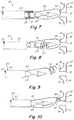
- FIG. 1is a perspective view of an exemplary medical device delivery system entering the right atrium of a heart in accordance with the present teachings
- FIG. 2is a perspective view of the exemplary medical device deployed at a target site between the left and right atrium of a heart in a constrained configuration
- FIG. 3is a perspective view of an exemplary medical device delivery system attaching to a deployed medical device according to the present teachings
- FIG. 4is a perspective view of an exemplary medical device delivery system of FIG. 3 , releasing a deployed medical device according to the present teachings;
- FIG. 6is a perspective view of an exemplary medical device delivery system attaching to a deployed medical device in accordance with the present teachings
- FIG. 8is a perspective view of an exemplary medical device delivery system in FIG. 7 releasing a deployed medical device in accordance with the present teachings;
- FIG. 11Ais a perspective view of an exemplary implant retention mechanism in FIG. 10 attaching to a deployed medical device in accordance with the present teachings;
- FIG. 11Bis a perspective view of an exemplary implant retention mechanism in FIG. 10 releasing a deployed medical device in accordance with the present teachings;
- FIG. 11Dis a perspective view of an exemplary implant retention mechanism in FIG. 10 releasing a deployed medical device in accordance with the present teachings
- FIG. 12is a perspective view of an exemplary medical device delivery system attaching to a deployed medical device in accordance with the present teachings
- FIG. 13is a perspective view of an exemplary medical device delivery system in FIG. 12 releasing a deployed medical device in accordance with the present teachings;
- FIG. 14Cis a perspective view of an exemplary implant retention mechanism in FIG. 12 attaching to a deployed medical device in accordance with the present teachings;
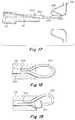
- FIG. 15is a perspective view of an exemplary medical device delivery system attaching to a deployed medical device in accordance with the present teachings
- FIG. 16is a perspective view of an exemplary medical device delivery system in FIG. 15 attaching to a deployed medical device in accordance with the present teachings;
- FIG. 17is a perspective view of an exemplary medical device delivery system in FIG. 15 releasing a deployed medical device in accordance with the present teachings;
- FIG. 18is a perspective view of an exemplary implant retention mechanism attaching to a deployed medical device in accordance with the present teachings
- FIG. 19is a perspective view of an exemplary implant retention mechanism attaching to a deployed medical device in accordance with the present teachings
- FIG. 20is a perspective view of an exemplary medical device delivery system attaching to a deployed medical device in accordance with the present teachings
- FIG. 21is a perspective view of an exemplary medical device delivery system in FIG. 20 releasing a deployed medical device in accordance with the present teachings;
- FIG. 22is a perspective view of an exemplary medical device delivery system attaching to a deployed medical device in accordance with the present teachings
- FIG. 23is a perspective view of an exemplary medical device delivery system in FIG. 22 releasing a deployed medical device in accordance with the present teachings;
- FIG. 25is a perspective view of an exemplary medical device delivery system attaching to a deployed medical device in accordance with the present teachings.
- FIG. 26is a perspective view of an exemplary medical device delivery system in FIG. 25 releasing a deployed medical device in accordance with the present teachings.
- the present teachingsprovide a delivery system comprising an implant retention mechanism for delivering a cardiac implant.
- the implant retention mechanismallows a clinician assesses an implant deployment with the implant free from strain imposed by the delivery system to the atrial septum.
- the present teachingscan be incorporated into delivery systems for many atrial implants, such as ASD closure devices, PFO closure implants, atria shunting devices, etc.
- a delivery systemgenerally can include a delivery sheath, a delivery catheter, and an implant retention mechanism.
- the delivery sheathhas a proximal end, a distal end, a longitudinal axis, and a longitudinal lumen extending from the proximal end to the distal end.
- the delivery catheteralso has a proximal end, a distal end, and a longitudinal axis. In some embodiments, the delivery catheter also has a longitudinal lumen extending from the proximal end to the distal end.
- an implantcan be folded into an elongated delivery configuration and stowed inside the longitudinal lumen of the delivery sheath.
- the distal end of the delivery catheteris in contact with the proximal end of the implant during the delivery.
- the implantin an elongated delivery configuration, slides over a distal end portion of the delivery catheter during the delivery.
- an implantcan be folded into an elongated delivery configuration and stowed inside the longitudinal lumen of the delivery catheter.
- proximalshall mean closest to the operator (less into the body) and “distal” shall mean furthest from the operator (further into the body). In positioning the medical device from a downstream access point, distal is more upstream and proximal is more downstream.
- delivery configurationrefers to the configuration of a device, such as an occluder, when it has a reduced profile in a delivery catheter.
- deployment configurationrefers to the configuration of a device, such as an occluder, when it is deployed from the catheter, such as at the desired implantation location.
- FIG. 2illustrates one such example, where a cardiac implant ( 10 ) is positioned through an aperture between the left and right atria.
- the term “aperture”refers to any anatomical anomalies such as a PFO, an ASD, a VSD, or an anatomical feature created for the purpose of creating a shunt. As shown in FIG.
- an exemplary implant deviceincludes a body portion ( 12 ), at least one distal flanges ( 14 ), and at least one proximal flanges ( 16 ) connecting to the body portion ( 12 ) at its distal end and the proximal end respectively.
- the body portion ( 12 ) of the implant deviceUpon deployment, as seen in FIG. 2 , the body portion ( 12 ) of the implant device is positioned through the aperture of the atrial septum, the distal flanges ( 14 ) of the device are positioned inside the left atrium contacting the septum, and the proximal flanges ( 16 ) of the device are positioned inside the right atrium contacting the septum.
- the distal flanges ( 14 ) and the proximal flanges ( 16 )are substantially annular and extend radially outward from the longitudinal axis of the body portion ( 12 ) as seen in FIG. 2 .
- the implant devicehas an elongated profile for percutaneous delivery through a delivery system and resumes a radially expanded profile upon deployment, as described in FIG. 2 .
- the implantexpands radially with its body portion ( 12 ) positioned through an aperture on the atrial septum, distal flange ( 14 ) apposed against the atrial septum in the left atrium, and proximal flange ( 16 ) apposed against the atrial septum in the right atrium.
- the implant deploymentis accomplished by either retracting the delivery sheath ( 22 ) proximally, or by extending the delivery catheter ( 24 ) distally, or a combination of both, thereby allowing the implant ( 10 ) exit the distal end of the delivery sheath, and resume its radially expanded profile.
- the implant deviceincludes at least one retention outlet working together with an implant retention mechanism.
- the retention outletis on the proximal flanges of the cardiac implant.
- the retention outletis on the body portion of the cardiac implant.
- the retention outletis on the distal portion of the cardiac implant.
- An implant retention outletis a hollow place in a solid body or surface of the implant which allows a wire or a filament to pass through one side of the outlet to the other side.
- an implant retention outletis a close loop, where an implant retention mechanism extends from one side of the solid body or surface of the cardiac implant to another, and can only be released by reversal of this movement.
- the present teachingsprovide a delivery system with an implant retention mechanism for percutaneous delivery of cardiac implants.
- the implant retention mechanismretains a deployed implant by engaging its implant retention outlet.
- a relatively flexible implant retention mechanismis used for implant retention.
- a relatively rigid implant retention mechanismis used for implant retention. Examples of these embodiments are described in detail below.
- a relatively flexible implant retention mechanismretains an implant during its deployment process, imposing minimum or no strain to the movement of the implant.
- the implant retention mechanismincludes a retention string that is not only strong enough to hold the implant securely, but also flexibly enough to allow the implant to be positioned naturally in the atrial septum and conform to the dynamic environment of a beating heart.
- the flexible implant retention mechanismis also strong enough to be used to retrieve a deployed implant by pulling the implant proximally back into its delivery catheter/sheath or a retrieval catheter/sheath.
- the flexible implant retention mechanismcan be used to guide implant retrieval by allowing an implant retrieval system to slide over the implant retention mechanism and locate/reach the implant.
- a flexible implant retention mechanismcan include an implant retention string. While the description above refers to strings, other terms, for example, filaments or sutures, are essentially interchangeable. One skilled in the art will also understand that certain metallic wires can also be used as the retention string, such as stainless steel wire, nitinol wire, etc. In addition, in some embodiments, each string, suture, or filament comprises one or more strings, sutures, or filaments.
- the implant retention stringcould be made from numerous materials, either polymeric or metallic.
- the polymeric retention string materialcan be polyglycolic acid (Biovek), polylactic acid, polydioxanone, and caprolactone, synthetics polypropylene, polyester or nylon etc.
- other non-absorbable retention string materialfor example, special silk, can be used.
- the cross section of the implant retention stringmay be circular or polygonal, such as square, or hexagonal. In another embodiment of the present teachings, the cross section of the implant retention string has a general diameter of 0.01 mm to 2 mm. In one embodiment of the present teachings, the implant retention string has a consistent cross section shape and size throughout its entire length. In another embodiment of the present teachings, the implant retention string has various shaped and sized cross section throughout its entire length. In one embodiment of the present teachings, the implant retention string has a length one to more than two times of the length of the delivery system.
- FIG. 3a delivery system ( 20 ) with a flexible implant retention mechanism ( 50 ) is used for delivering a cardiac implant ( 10 ).
- FIG. 3illustrates a cardiac implant ( 10 ) deployed in the heart (not shown) with an exemplary flexible implant retention mechanism ( 50 ) still engaging the implant ( 10 ).
- the delivery system ( 20 )includes a delivery sheath ( 22 ), which includes a distal end, a proximal end, and a longitudinal lumen extending, along a longitudinal axis, from the proximal end to the distal end; a delivery catheter ( 24 ), which includes a proximal end and a distal end and is slidably disposed within the longitudinal lumen of the delivery sheath ( 22 ); and a flexible implant retention mechanism ( 50 ), which includes, among others, an implant retention string ( 52 ) with a fixed end ( 54 ) and a free end ( 56 ).
- the exemplary implant retention mechanism ( 50 )includes a retention string ( 52 ) with a fixed end ( 54 ) (not shown) and a free end ( 56 ) (not shown).
- the fixed end of the retention stringis connected to a distal end portion of the delivery catheter ( 24 ).
- the free end ( 56 ) of the retention stringextends from the distal end portion of the delivery catheter ( 24 ), crosses the retention outlet ( 18 ) on the implant ( 10 ), extends proximally through the lumen of the delivery sheath ( 22 ), and exits the proximal end of the delivery sheath ( 22 ).
- the implant ( 10 )has a longitudinal lumen ( 8 ) extending from one end of the body portion ( 12 ) to the other end of the body portion ( 12 ), so that the body portion ( 12 ) of the implant ( 10 ) has an outer surface which faces, and contacts, the septum at atrial aperture, and an inner surface which faces the longitudinal lumen ( 8 ).
- the implant retention outlet ( 18 )is located on the body portion ( 12 ) of the implant ( 10 ).
- the free end ( 56 ) (not shown) of the flexible retention string ( 52 )extends along the outer surface of the body portion ( 10 ); crosses the implant retention outlet ( 18 ); extends proximally along the inner surface of the body portion ( 10 ), through the longitudinal lumen ( 8 ) of the body portion ( 12 ) of the implant ( 10 ), and further proximally through the longitudinal lumen of the delivery sheath ( 22 ); and exits the proximal end of the delivery sheath ( 22 ).
- the free end ( 56 ) of the flexible retention string ( 52 )extends along the longitudinal lumen ( 8 ) of the body portion ( 10 ) of the implant ( 10 ), crosses the implant retention outlet ( 18 ), extends proximally along the outer surface of the body portion ( 12 ), and further proximally through the lumen of the delivery sheath ( 22 ), and exits the proximal end of the delivery sheath ( 22 ).
- the implant retention outlet ( 18 )is located on a proximal flange ( 16 ) of the implant ( 10 ).
- the proximal flange ( 16 )retracts radially, forming an elongated proximal flange portion ( 16 ) with a longitudinal lumen, so that the elongated proximal flange portion ( 16 ) of the implant ( 10 ) has an outer surface which, when deployed, faces, and contacts, the septum at atrial aperture, and an inner surface which, when deployed, faces the right atrium.
- the free end ( 56 ) of the flexible retention string ( 52 )extends along the outer surface of the elongated proximal flange portion ( 16 ), crosses the implant retention outlet ( 18 ), extends proximally along the inner surface of the elongated proximal flange portion ( 16 ), further proximally through the lumen of the delivery sheath ( 22 ), and exits the proximal end of the delivery sheath ( 22 ).
- the free end ( 56 ) of the flexible retention string ( 52 )extends along the inner surface of the elongated proximal flange portion ( 16 ), crosses the implant retention outlet ( 18 ), extends proximally along the outer surface of the elongated proximal flange portion ( 16 ), further proximally through the lumen of the delivery sheath ( 22 ), and exits the proximal end of the delivery sheath ( 22 ).
- flexibility of the implant retention string ( 52 )allows a clinician to maintain contact with the implant ( 10 ), while the implant ( 10 ) conforms to the anatomy of the atrial septum. Such embodiment allows a clinician to assess the true status of an implant deployment before releasing the implant. Such embodiment also eliminates the risk of shifting the implant position when the implant is released from the delivery system ( 20 ).
- a cliniciancan use an implant retrieval mechanism, for example, by sliding it over the retention string ( 52 ), to retrieve the implant ( 10 ).
- a cliniciancan retrieve the implant ( 10 ) by retracting implant retention string ( 52 ) proximally, thereby pulling the implant ( 10 ) back into a delivery/retrieval sheath from the distal end.
- the fixed end of the flexible retention string ( 52 )is connected to the distal end portion of the delivery catheter ( 24 ) and the free end of the flexible retention string ( 52 ), after crossing the implant retention outlet, extends through the lumen of the delivery sheath ( 22 ).
- the fixed end ( 54 ) of the flexible retention string ( 52 )is connected to the distal end portion of the delivery catheter ( 24 ) and the free end ( 56 ) of the flexible retention string ( 52 ), after crossing the implant retention outlet, extends through the lumen of the delivery catheter ( 24 ).
- the fixed end ( 54 ) of the flexible retention string ( 52 )is connected to the distal end portion of the delivery sheath ( 22 ) and the free end ( 56 ) of the flexible retention string ( 52 ), after crossing the implant retention outlet, extends through the lumen of the delivery sheath ( 22 ).
- the fixed end ( 54 ) of the flexible retention string ( 52 )is connected to the distal end portion of the delivery sheath ( 22 ) and the free end ( 56 ) of the flexible retention string ( 52 ) after crossing the implant retention outlet, extends through the lumen of the delivery catheter ( 24 ).
- the fixed end ( 54 ) of the flexible retention string ( 52 )is connected to the delivery system handle (not shown) and the free end ( 56 ) of the flexible retention string ( 52 ), after crossing the implant retention outlet, extends through the lumen of the delivery catheter ( 24 ) or delivery sheath ( 22 ).
- the fixed end of the retention string ( 54 )(not shown) is then retracted proximally by pulling the delivery catheter ( 24 ) or delivery sheath ( 22 ) proximally, allowing the free end ( 56 ) of the flexible retention string ( 52 ) to move distally, releasing the string ( 52 ) from the implant retention outlet ( 18 ), and completely releasing the implant ( 10 ).
- FIGS. 5A-Dillustrate cross-section profiles of an exemplary delivery system ( 20 ) with a flexible implant retention mechanism ( 50 ).
- the cross-section of the delivery system ( 20 )includes an exemplary cross-section of the delivery sheath ( 22 ), an exemplary cross-section of the delivery catheter ( 24 ), and an exemplary cross-section of the flexible retention string ( 52 ).
- FIG. 5Aillustrates one embodiment of the present teachings, where a lumen is formed in the delivery sheath ( 22 ). This lumen is configured to contain a flexible retention string ( 52 ), both extending distally from its fixed end ( 54 ) to the implant ( 10 ), and extending proximally from the implant back to its free end ( 56 ).
- FIGS. 5C and 5Dillustrate exemplary embodiments of the cross-section profiles of the delivery system ( 20 ), it should be understood by those skilled in the art that other cross section profile can also be used to achieve the same or equivalent purpose
- the implanthas a retention outlet ( 18 ), as illustrated in FIG. 3 .
- the implanthas two retention outlets ( 18 a , 18 b ), positioned opposite from each other radially across a longitudinal axis of the implant ( 10 ).
- FIG. 6illustrates an implant being deployed while still being retained by the flexible retention mechanism to the delivery system.
- FIG. 6illustrates an implant being deployed while still being retained by the flexible retention mechanism to the delivery system.
- the free end ( 56 ) of the flexible retention string ( 52 )extends distally from the distal end portion of the delivery catheter ( 24 )/sheath ( 22 ), crosses the first implant retention outlet ( 18 a ), continuously extends radially across the longitudinal axis of the implant, crosses the second retention outlet ( 18 b ), extends proximally through the lumen of the delivery catheter ( 24 )/sheath ( 22 ), and exits from the proximal end of the delivery catheter ( 24 )/sheath ( 22 ).
- the implant retention outletsevenly distribute across the cross-section of the implant.
- the spacing between the retention outletsvaries from one to another.
- the flexible retention stringextends across all retention outlets.
- the retention stringextends across some of the retention outlets.
- the fixed end ( 54 ) of the flexible retention string ( 52 )is attached to the delivery catheter ( 24 )/sheath ( 22 ) by a mechanical means including a screw, a bolt, a clamp or the like; a chemical means, including an adhesive or the like; a thermal means, including ultrasonic welding, laser welding, overmolding, or the like; or other attachment means known to those skilled in the art.
- the fixed end ( 54 ) of the flexible retention string ( 52 )attaches to the delivery catheter ( 24 ) by wrapping circumferentially around a portion of the deliver catheter ( 24 ) in one or more loops, and such loop(s) are trapped by the delivery sheath ( 22 ) during the implant deployment preventing it from unwrapping itself.
- the wrapped loop of the flexible retention string ( 52 )remains trapped by the delivery sheath ( 22 ) so that the fixed end ( 54 ) of the flexible retention string ( 52 ) remains attached to the delivery catheter ( 24 ), and the implant retention string ( 52 ) maintains its hold to the implant ( 10 ).
- the delivery catheter ( 24 )can be retracted proximally within the lumen of the delivery sheath ( 22 ), thereby pulling the flexible retention string ( 52 ) proximally, and thereby pulling implant ( 10 ) proximally back into the delivery sheath ( 22 ).
- an implant retrieval mechanismcan slide over the flexible retention string ( 52 ) and capture the implant ( 10 ).
- the delivery sheath ( 22 )is pulled proximally, exposing the wrapped loop of the fixed end ( 54 ) of the flexible retention string ( 52 ).
- the fixed end ( 54 )releases its attachment to the delivery catheter ( 24 ).
- the free end ( 56 ) of the flexible retention string ( 52 )is then retracted proximally, as illustrated in FIG. 9 , pulling the newly freed fixed end ( 54 ) distally first, allowing the newly freed fixed end ( 54 ) of the flexible retention string ( 52 ) to be released from the implant ( 10 ) and to be completely removed from the body.
- the advantage of the embodiment as described in FIG. 7is that because the fixed end ( 54 ) of the flexible retention string ( 52 ) can be placed closer to the implant ( 10 ), the length of the flexible retention string ( 52 ) to be retracted by a clinician during the procedure is much shorter for releasing the implant ( 10 ), comparing to the embodiment described in FIG. 3 .
- the wrapped loopis trapped by the delivery sheath ( 22 ).
- the wrapped loop over the delivery catheter ( 24 )is trapped by another outer sheath that is slidably disposed over the delivery catheter ( 24 ).
- the fixed end ( 54 ) of the flexible retention string ( 52 )is wrapped around a portion of the delivery sheath ( 22 )
- the wrapped loopis trapped by another outer sheath that is slidably disposed over the delivery sheath ( 22 ).
- the circumference of the delivery catheter ( 24 )is modified circumferentially at the place where the fixed end ( 54 ) of the flexible retention string ( 52 ) is wrapped around. Such modification allows the overall circumference of the wrapped retention string align with the adjacent surface of the delivery catheter ( 24 ), so that no extra friction is introduced when the delivery catheter ( 24 ) slides inside the lumen of the delivery sheath ( 22 ), or outer sheath.
- the overall circumference of the delivery catheter at where the retention string wrapped aroundis greater than that of the adjacent surface of the delivery catheter ( 24 ) so that the wrapped loop is secured by the delivery sheath or outer sheath, preventing the loop from untying itself during an implant delivery and deployment.
- the present teachingsalso disclose other embodiments of the flexible implant retention mechanism.
- the flexible retention string ( 52 )is tied to the implant ( 10 ) through the implant retention outlet ( 18 ), forming an exploding knot ( 58 ).
- the term “exploding knot”means a knot that can untie itself with one tug of one end of the string, leaving no tangle.
- an exploding knotincludes one end of the flexible retention string ( 52 ), represented as “Fr” (i.e., free end), and the other end of the flexible retention string ( 52 ), represented as “Fi” (i.e., fixed end).
- Exploding knot ( 58 )requires a balance between being tight enough to hold the implant securely and being loose enough to let the string slide through when the “Fr” end is pulled.
- both “Fi” end and “Fr” ends of the flexible retention string ( 52 )extend proximally through the longitudinal lumen of the delivery catheter ( 24 )/sheath ( 22 ) similar to what has been described above, and exit the proximal end of the delivery catheter ( 24 )/sheath ( 22 ).
- the “Fi” end of the flexible retention string ( 52 )is held closely so that, the exploding knot ( 58 ) is secured, the flexible retention string ( 52 ) retains the implant firmly, and the implant ( 10 ) remains in contact with the clinician.
- such flexible retention string ( 52 )can be used to pull the implant ( 10 ) proximally back into the delivery sheath ( 22 ).
- an implant retrieval mechanismcan be advanced over the flexible retention string ( 52 ) and capture the implant ( 10 ).
- a clinicianpulls the “Fr” end of the flexible retention string ( 52 ) proximally to untie the exploding knot ( 58 ), and then retracts the “Fr” end of the flexible retention string ( 52 ) further proximally to allow the “Fi” end of the flexible retention string ( 52 ) to extend distally through the implant retention outlet ( 18 ), releasing the implant ( 10 ) from flexible retention string ( 52 ).
- a cliniciancan then retract the “Fi” end of the flexible retention string ( 52 ) proximally and release the implant ( 10 ).
- the flexible retention string ( 52 )is tied directly to the implant ( 10 ).
- the flexible retention string ( 52 )upon crossing the implant retention outlet ( 18 ), is tied to a portion of the delivery catheter ( 24 ) or the delivery sheath ( 22 ).
- the “Fi” end of the flexible retention string ( 52 )is held firmly throughout an implant delivery and deployment process.
- the “Fi” end of the flexible retention string ( 52 )is let free at where is close to the exploding knot.
- a cliniciancan further retract the “Fr” end of the flexible retention string ( 52 ) proximally, allow the “Fi” end of the retention string ( 52 ) to be released from the implant retention outlet ( 18 ), thereby releasing the implant ( 10 ).
- the advantage of such embodimentis that because the “Fi” end of the flexible retention string ( 52 ) is closer to the implant ( 10 ), the length of the flexible retention string ( 52 ) to be retracted by a clinician during the procedure is much shorter for releasing the implant ( 10 ), comparing to the embodiment described otherwise.
- FIGS. 11A-Billustrate the details of an example of an exploding knot ( 58 ) according to one embodiment of the present teachings.
- FIG. 11Aillustrates an exploding knot ( 58 ) having two coils ( 60 a , 60 b ) holding a double-over portion ( 62 ) of the string. The knot is tightened by pulling the “Fi” end of the string.
- a clinicianwould pull the “Fr” end of the string to pulled out the double-over portion ( 62 ) of the string from the two coils ( 60 a , 60 b ), thereby untying the exploding knots ( 58 ).
- the cliniciancan then release the retained implant by proximally pulling either the “Fr” end or the “Fi” end of the flexible retention string ( 52 ).
- FIGS. 11C-Dillustrate the details of another example of an exploding knot ( 58 ).
- FIG. 11Cillustrates that the knot is formed by forming a loop ( 78 ) at a portion of the flexible retention string ( 52 ) toward its “Fr” end. A portion towards the “Fi” end of the string ( 52 ) forms a first double-over ( 80 ) and extends through the loop ( 78 ). Then, the portion of the string toward the “Fr” end forms a second double-over ( 82 ) and extends through the loop of the first double-over ( 80 ). The knot ( 58 ) is tightened by pulling the “Fi” end of the string ( 52 ). To untie the knot, as illustrated in FIG.
- a clinicianpulls the “Fr” end of the string ( 52 ) so that the second double-over portion ( 82 ) of the string ( 52 ) is pulled out of the loop of the first double-over ( 80 ).
- the clinicianreleases the retained implant ( 10 ) by pulling the “Fi” end of the flexible retention string ( 52 ) to pull the first double-over portion ( 80 ) of the string ( 52 ) out of the first loop ( 78 ).
- the implantis then released by proximally pulling either the “Fr” end or the “Fi” end of the retention string ( 52 ).
- the present teachingsalso include a delivery system with a rigid implant retention mechanism. Similar to the above described flexible implant retention mechanisms, the rigid implant retention mechanism also imposes minimum or no strain to the implant so that a clinician can assess the true deployment status, i.e., that the deployment position will not be changed during or after releasing the implant.
- a rigid implant retention mechanismincludes an implant retention wire which holds the implant securely during implant delivery and deployment, and allows the implant to be positioned naturally against the atrial septum conforming to the dynamic environment of the heart.
- rigidis used here to arbitrarily differentiate some embodiments from other embodiments, in which the implant retention mechanism in the some embodiments is relatively (e.g., slightly, moderately, or significantly) more rigid than that in the other embodiments.
- the terms “rigid” and “relatively rigid”are interchangeable.
- the rigid implant retention mechanismcan be used to retrieve a deployed implant by pulling the implant back into its delivery catheter/sheath or a retrieval catheter/sheath.
- the rigid implant retention mechanismcan be used to guide implant retrieval by allowing an implant retrieval system to slide over the implant retention mechanism and locate/reach the implant.
- a rigid implant retention mechanismcan include an implant retention wire. While the description herein refers to wires, other terms, for example, cable or lead, are essentially interchangeable. In addition, in some embodiments, each wire, cable, or lead comprises one or more wires, cables, or leads.
- the implant retention wirecould be made of a variety of materials, including a metal, an alloy (e.g., a stainless steel or Nitinol), or a plastic.
- the cross section of the implant retention stringmay be circular or polygonal, such as square, or hexagonal.
- the implant retention wirehas a uniform diameter of 0.1 mm to 1 mm throughout its entire length.
- the implant retention wirehas a uniform diameter of 2 mm to 5 mm throughout its entire length.
- the implant retention wirecan have a smaller diameter toward its distal end portion for increased flexibility.
- the implant retention wirecan have a gradually decreased diameter from its proximal end toward its distal end.
- the implant retention wireincludes a reduced diameter “neck” portion to increase the flexibility at its distal end portion.
- FIG. 12a delivery system ( 110 ) with a rigid implant retention mechanism ( 120 ) is used for delivering a cardiac implant ( 100 ).
- FIG. 12illustrates a cardiac implant ( 100 ) deployed in the heart (not shown) with the rigid implant retention mechanism ( 120 ) still engaging the implant ( 100 ).
- the delivery system ( 110 )includes a delivery sheath ( 112 ) having a distal end, a proximal end, and a longitudinal lumen extending along a longitudinal axis from its proximal end to its distal end; a delivery catheter ( 114 ) having a proximal end and a distal end and slidably disposed within the longitudinal lumen of the delivery sheath ( 112 ); and a relatively rigid implant retention mechanism ( 120 ) having an implant retention wire ( 122 ) with a fixed end ( 124 ) and a free end ( 126 ).
- the implant retention mechanism ( 120 )includes a wire ( 122 ) with a fixed end ( 124 ) attached to a distal end portion of the delivery catheter ( 114 ) and a free end ( 126 ) extending from the distal end portion of the delivery catheter ( 114 ), crossing a retention outlet ( 108 ) on the implant device ( 100 ), extending proximally, and being then releasably secured by the delivery system ( 110 ), for example by the delivery sheath ( 112 ) alone, the delivery catheter ( 114 ) alone, or a combination of the delivery catheter ( 112 ) and delivery sheath ( 114 ).
- the implant device ( 100 )has a longitudinal lumen ( 106 ) extending from one end of the body portion ( 102 ) to the other end of the body portion ( 102 ), so that the body portion ( 102 ) of the implant ( 100 ) has an outer surface which faces, and contacts, the septum at atrial aperture, and an inner surface which faces the longitudinal lumen ( 106 ).
- the implant retention outlet ( 108 )is located on the body portion ( 102 ) of the implant ( 100 ).
- the free end ( 126 ) of the rigid retention wire ( 122 )extends along the outer surface of the body portion ( 102 ), crosses the implant retention outlet ( 108 ), extends proximally along the inner surface of the body portion ( 102 ), through the longitudinal lumen ( 106 ) of the body portion ( 102 ) of the implant ( 100 ), further proximally through the longitudinal lumen of the delivery sheath ( 112 ), and is releasably secured by the delivery system ( 110 ).
- the free end ( 126 ) of the rigid retention wire ( 122 )extends along the outer surface of the body portion ( 102 ), crosses the implant retention outlet ( 108 ), extends proximally along the inner surface of the body portion ( 102 ), through the longitudinal lumen ( 106 ) of the body portion ( 102 ) of the implant ( 100 ), further proximally through the longitudinal lumen of the delivery sheath ( 112 ), and is releasably secured by the delivery system ( 110 ).
- the implant retention outlet ( 108 )is located on a proximal flange ( 104 ) of the implant ( 100 ).
- the proximal flanges ( 104 )are retracted radially, forming an elongated proximal flange portion ( 104 ) with a longitudinal lumen, so that the elongated proximal flange portion ( 104 ) of the implant ( 100 ) has an outer surface which, when deployed, faces, and contacts, the septum at atrial aperture, and an inner surface which, when deployed, faces the right atrium.
- the free end ( 126 ) of the rigid retention wire ( 122 )extends along the inner surface of the elongated proximal flange portion ( 104 ), crosses the implant retention outlet ( 108 ), extends proximally along the outer surface of the elongated proximal flange portion ( 104 ), further proximally through the lumen of the delivery sheath ( 112 ), and is releasably secured by the delivery system ( 110 ).
- the flexibility of the implant retention wire ( 122 )allows a clinician to maintain contact with the implant ( 100 ), without introducing strain on the implant ( 100 ), thereby allowing an implant ( 100 ) to conform to the anatomy of the atrial septum.
- Such embodimentsallow a clinician to assess the true status of an implant deployment before releasing the implant.
- Such embodimentsalso eliminate the risk of shifting the implant position when the implant is released from the delivery system ( 110 ).
- a cliniciancan advance a device retrieval mechanism, for example, by sliding it over the retention wire ( 122 ), to retrieve the implant ( 100 ).
- a cliniciancan retrieve the implant ( 100 ) by retracting implant retention wire ( 122 ) proximally, thereby pulling the implant ( 100 ) back into a delivery/retrieval sheath from the distal end.
- the cliniciancan distally extend the delivery catheter ( 114 ) and/or proximally retract the delivery sheath ( 112 ) to slide a distal portion of the delivery catheter ( 114 ) outside of the deliver sheath ( 112 ).
- the cliniciancan distally extend the delivery catheter ( 114 ) and/or proximally retract the delivery sheath ( 112 ) to slide a distal portion of the delivery catheter ( 114 ) outside of the deliver sheath ( 112 ).
- the free end ( 126 ) of the retention wire ( 122 )is released from its attachment to the delivery catheter ( 114 ).
- the fixed end ( 124 ) of the retention wire ( 122 )is attached to the delivery catheter ( 114 ) by a mechanical means, including a screw, a bolt, or the like; a chemical means, including an adhesive and the like; a thermal means, including ultrasonic welding, laser welding, overmolding, or the like; or other suitable attachment means.
- the retention wire ( 122 )has an elasticity or a shape memory, allowing the free end ( 126 ) of the retention wire to be constrained by the delivery sheath ( 112 ) during implant delivery and deployment, and allowing the retention wire ( 122 ) to resume a relatively straight profile after its free end ( 126 ) released from the delivery sheath ( 112 ).
- the inner dimension of the delivery sheath ( 112 )can be slightly smaller than the combined outer circumference of the retention wire ( 122 ) and the delivery catheter ( 114 ).
- the portion of the outer surface of the delivery catheter ( 114 ) where the free end ( 126 ) of the retention wire ( 122 ) endsis modified so that the overall outer circumference of the delivery catheter ( 114 ) combining with the retention wire ( 122 ) aligns with the proximal adjacent outer surface of the delivery catheter ( 114 ).
- the outer circumference of the distal portion of the delivery catheter ( 114 ) to the modified portion of the delivery catheter ( 114 )remains unchanged.
- this portion ( 123 ) of the delivery catheter ( 114 ) combining with the retention wire ( 122 )creates an interference with the inner dimension of the delivery sheath ( 112 ), thereby securing the free end ( 126 ) of the retention wire ( 122 ).
- the free end ( 126 ) of the retention wire ( 122 )is secured because the outer dimension of the free end ( 126 ) of the retention wire ( 122 ) is greater than the key slot ( 130 ) on the outer surface of the delivery catheter ( 114 ), so that the combined outer dimension of the retention wire ( 122 ) and delivery catheter ( 114 ) remains greater than the inner dimension of the delivery sheath ( 112 ), thereby creating an interference securement.
- the outer profile of the free end ( 126 ) of the retention wire ( 122 )is greater than the portion of the retention wire ( 122 ) next to the free end ( 126 ), and the corresponding dimension of the key slot ( 130 ) is greater than the key way ( 128 ).
- the enlarged free end ( 126 ) of the retention wire ( 122 )is trapped even when the combined outer dimension of the free end ( 126 ) of the retention wire ( 122 ) and delivery catheter ( 114 ) is not greater than the inner dimension of the delivery sheath ( 112 ).
- FIG. 14Billustrates a ball configuration of the enlarged free end ( 126 ) of the retention wire ( 122 ) and a socket configuration of the key slot ( 130 ) on the delivery catheter ( 114 ) for holding the ball.
- FIG. 14Cillustrates a cone configuration of the enlarged free end ( 126 ) of the retention wire ( 122 ) with the largest dimension at the very end and a matching cone shaped key slot ( 130 ) for holding the cone.
- FIG. 14Dillustrates an enlarged coiled tip at the free end ( 126 ) of the retention wire ( 122 ) and a matching key slot ( 130 ) on the surface of the delivery catheter ( 114 ) for holding the coiled tip.
- the clinicianwithdraws the delivery sheath ( 112 ) proximally, completely exposing the free end ( 126 ) of the implant retention wire ( 122 ).
- the clinicianwithdraws the delivery catheter ( 114 ) further proximally, thereby releasing the free end ( 126 ) of the retention wire ( 122 ) from the implant retention outlet ( 108 ), thereby releasing the implant ( 100 ).
- the cross-section of the delivery catheter ( 114 )is modified for the implant retention wire ( 122 ). Similar to the embodiments shown in FIG. 5B , two lumens are formed between the delivery sheath ( 112 ) and the delivery catheter ( 114 ) with one for the retention wire ( 122 ) extending from its fixed end ( 124 ) to the implant ( 100 ), and the other for the retention wire ( 122 ) extending from its freed end ( 126 ) to the implant ( 100 ).
- only one lumenis formed between the delivery sheath ( 112 ) and the delivery catheter ( 114 ), which allow both the retention wire ( 122 ) extending from its fixed end ( 124 ) to the implant ( 100 ), and the retention wire ( 122 ) extending from the implant ( 100 ) to its freed end ( 126 ).
- a lumen ( 210 ) formed between the delivery sheath ( 112 ) and the delivery catheter ( 114 )holds an implant retention mechanism ( 200 ) including an elongated tube ( 202 ), an implant retention mandrel ( 204 ) and an implant retention wire ( 206 ). As illustrated in FIG.
- the elongated tube ( 202 )is slidably disposed within the lumen ( 210 ) firmed by the delivery sheath ( 112 ) and the delivery catheter ( 114 ), the elongated implant retention mandrel ( 204 ) is slidably disposed within the elongated tube ( 202 ), and the implant retention wire ( 206 ) having a fixed end connected to a distal end portion of the implant retention mandrel ( 204 ).
- the implant retention wire ( 206 )also has a free end which is releasably secured by the implant retention mechanism ( 200 ), such as between the elongated tube ( 202 ) and the implant retention mandrel ( 204 ).
- FIG. 15illustrates a deployed implant retained by a retention wire.
- the implantis free from constrain by the delivery sheath and the delivery catheter and is attached to the implant retention wire ( 206 ) with its free end stowed within the elongated tube ( 202 ) of the implant retention mechanism ( 200 ).
- a cliniciancan retract the entire implant retention mechanism ( 200 ) proximally with the free end of the retention wire ( 206 ) remaining inside the elongated tube ( 202 ), thereby pulling the implant back into the delivery sheath.
- a clinicianretracts the elongated tube ( 202 ) proximally while holding the retention mandrel ( 204 ) steady, releases the free end of the implant retention wire ( 206 ) from its constraint.
- the implant retention mandrel ( 204 )can be pushed distally while the elongated tube ( 202 ) is held steady, thereby exposing the free end of the implant retention wire ( 206 ).
- the retention wireresumes its predefined relatively straight profile.
- a cliniciancan then retract the implant retention mandrel ( 204 ) further proximally, allowing the free end of the retention wire ( 206 ) to be released from the implant retention outlet and thereby releasing the implant.
- the releasable securement of the free end of the retention wire ( 206 ) by the elongated tube ( 202 )is achieved by either an interference force or the elasticity or the shape memory property of the retention wire ( 206 ).
- the above-described details with reference to FIGS. 12-14are therefore incorporated herein.
- a distal end portion of the implant retention mandrel ( 204 )can be modified in such a way to accommodate the releasable securement of the free end of the retention wire ( 206 ).
- the above-described details with reference to FIGS. 12-14are therefore incorporated herein.
- implant retention wires ( 302 )are slidably disposed within a longitudinal lumen of the delivery sheath side by side to the delivery catheter. As illustrated in FIG. 18 , the proximal end ( 304 ) of the retention wire ( 302 ) extends outside of the proximal end ( 304 ) of the delivery sheath/catheter, and connects to the control of the implant retention wire ( 302 ).
- the free end ( 306 ) of the retention wire ( 302 )extends distally, crosses the implant retention outlet, turns and extends proximally, and enters the longitudinal lumen of the delivery catheter/sheath from its distal end.
- the resilient, elastic, or shape memory property of the retention wireallows the free end ( 306 ) of the retention wire ( 302 ) to remain inside the lumen during implant delivery and deployment.
- the resilient, elastic, or shape memory property of the retention wireallows the retention wire to resume its predefined relatively straight profile.
- the implant retention wire ( 302 )retains the implant at its retention outlet.
- a clinicianuses the control of the implant retention mechanism ( 300 ), retracts the implant retention wire ( 302 ) back into delivery catheter/sheath.
- a retrieval mechanismcan be incorporated with the delivery system and the implant retention mechanism for retrieving the deployed implant.
- the implant retention wire ( 302 )extends distally until its free end ( 306 ) beyond the distal end of the delivery catheter/sheath. As the free end ( 306 ) of the retention wire ( 300 ) exits the distal end of the delivery catheter/sheath, the distal portion of the retention wire ( 302 ) is straightened due to the resilient, elastic, or shape memory property. A clinician then retracts the retention wire ( 302 ) further proximally, allowing the free end ( 306 ) of the retention wire ( 302 ) to be released from the implant retention outlet, thereby releasing the implant.
- FIG. 19illustrates another embodiment of the present teachings where a bulge ( 310 ) is presented on a distal end portion of the retention wire ( 302 ) close to where the retention wire ( 302 ) crosses the implant retention outlet.
- a bulge ( 310 )is proximal to the retained implant and on the proximal end ( 304 ) side of the retention wire ( 302 ).
- the bulge ( 310 ) of the retention wire ( 302 )can be on the free end ( 306 ) side of the retention wire ( 302 ).
- the bulge ( 310 ) of the retention wire ( 302 )has a greater profile than the inner lumen of the delivery catheter/sheath.
- the bulge ( 310 ) of the retention wire ( 302 )creates an additional securement during an implant delivery and deployment.
- the bulge ( 310 )can have feature to capture free end ( 306 ) of retention wire ( 302 ).
- the bulgeis formed by extra material deposited on the retention wire by mechanism means, chemical means or thermal means; or an integrated part of the retention wire itself.
- a delivery systemincludes a delivery sheath having a distal end, a proximal end, and a longitudinal lumen extending along a longitudinal axis from its proximal end to its distal end; a delivery catheter having a proximal end and a distal end and slidably disposed within the longitudinal lumen of the delivery sheath; and rigid implant retention mechanism used for retaining an implant.
- FIG. 20only illustrates a distal portion of the delivery system 400 , with a delivery catheter ( 404 ) slidably disposed within the longitudinal lumen of the delivery sheath ( 402 ), and an implant retention mechanism retaining a deployed implant through the implant retention outlet.
- the implanthas a longitudinal lumen extending from one end of the body portion to the other end of the body portion, so that the body portion of the implant has an outer surface which faces, and contacts, the septum at atrial aperture, and an inner surface which faces the longitudinal lumen.
- the implant retention outletis located on the body portion of the implant.
- the implant retention outletis located on the proximal flanges of the implant.
- the implant retention outletis located on the distal flanges of the implant.
- the implantis stretched to an elongated delivery profile, with a proximal portion of the implant slidably disposed over a distal portion of the delivery catheter.
- the implant retention mechanismillustrated in FIG. 20 , includes a retention wire ( 408 ) having a proximal end (not shown) and a distal bend ( 410 ), and a retention wire cavity ( 412 ), for receiving the distal bend end of the retention wire, on a distal end portion of the delivery catheter ( 404 ).
- the proximal end of the retention wireconnects to the delivery catheter ( 404 ) by a mechanical means, for example, a screw, a bolt, or the like; a chemical means, for example, an adhesive or the like; a thermal means, for example, ultrasonic welding, laser welding, overmolding, or the like; or other suitable attachment means.
- the proximal end of the retention wireextends proximally inside the longitudinal lumen of the delivery sheath, and exits the proximal end of the delivery sheath.
- the retention wirecan have a radial bend ( 410 ) at its distal end toward the longitudinal axis of the delivery catheter and/or implant.
- the end of the distal bend ( 410 ) of the retention wire ( 408 )extends along the outer surface of the elongated implant, crosses the implant retention outlet on the implant, and reaches the retention wire cavity ( 412 ) on the delivery catheter ( 404 ).
- the retention wire cavity ( 412 )forms an angle of 5° to 90° with the longitudinal axis of the delivery catheter ( 404 ).
- the implant retention wire ( 408 )has a strained “stowed” configuration and a relaxed radially expanded configuration. In its stowed configuration, the delivery sheath slides over the implant retention wire ( 408 ) so that the distal bend ( 410 ) of the retention wire ( 408 ) remains inside the wire retention cavity ( 412 ), thereby allowing the implant retention mechanism retains the implant.
- the distal bend ( 410 ) of the retention wire ( 408 )expands radially outward, releasing the end of the distal bend ( 410 ) of the retention wire ( 408 ) from the retention wire cavity ( 412 ) and the implant retention outlet, thereby releasing the implant from its attachment to implant retention mechanism.
- the entire retention wire ( 408 ) including its distal bend ( 410 )is slidably disposed within the delivery sheath ( 402 ).
- the entire retention wire ( 408 ) including its distal bend ( 410 )is slidably disposed within the delivery sheath ( 402 ).
- only a proximal portion of the retention wire ( 408 )is disposed within the delivery sheath ( 402 ).
- the entire retention wire ( 408 ) including its proximal endis exposed outside of the delivery sheath ( 402 ).
- the entire retention wire ( 408 ) including its proximal endis exposed outside of the delivery sheath ( 402 ).
- only a distal portion of the retention wire ( 408 )is exposed outside of the delivery sheath ( 402 ).
- the delivery sheath ( 402 )includes a major longitudinal lumen for the delivery catheter ( 404 ) and a separate side retention wire lumen ( 406 ) for the retention wire ( 408 ) to be slidably disposed within.
- the delivery catheter ( 404 )is slidably disposed within the major longitudinal of the delivery sheath ( 402 ) and the retention wire ( 408 ) is slidably disposed within the side lumen ( 406 ).
- the delivery sheath ( 402 )has only one longitudinal lumen where both the delivery catheter ( 404 ) and the retention wire ( 408 ) are disposed within.
- the retention wirehas a size of 0.010′′, 0.011′′, 0.014′′, 0.018′′, 0.021′′, 0.028′′, 0.035′′, 0.038′′, 0.042′′ or 0.045′′. In other embodiments of the present teachings, the retention wire has a size in the range of 0.010′′ and 0.045′′.
- the implant retention wire ( 408 )retains the implant at its retention outlet as an implant is deployed.
- the implantis free from strain introduced by the delivery sheath and the delivery catheter.
- Such an embodimentallows a maximum freedom of movement of the implant, thereby allowing a deployed implant to be positioned naturally against/in the septum.
- a cliniciandecides that the implant deployment is not satisfactory, he/she can retract the entire implant retention mechanism, including the delivery catheter ( 404 ), implant retention wire ( 408 ) with its distal bend end remaining inside the retention wire cavity ( 412 ), proximally, thereby pulling the implant proximally back into the delivery sheath ( 402 ).
- a clinicianretracts the delivery sheath ( 402 ) proximally while holding the delivery catheter ( 404 ) steady, allowing the retention wire ( 408 ) resume its relaxed radially expanded configuration.
- the implant retention mechanismincluding the delivery catheter ( 404 ) and implant retention wire ( 408 ) is pushed distally while the delivery sheath ( 402 ) is held steady, allowing the retention wire ( 408 ) resume its relaxed radially expanded configuration.
- the distal bend of the implant retention wire ( 408 )extends radially outward, releases from the retention cavity on the delivery catheter ( 404 ) and implant retention outlet, and the implant is thereby released from the implant retention mechanism.
- the delivery system along with implant retention mechanismcan be removed from the body.
- FIGS. 22-23the implant can be retained via other exemplary embodiments of the retention wire.
- the embodiment illustrated in FIG. 22has a similar delivery system and implant configuration to what has been described above with reference to FIG. 20 .
- the above-described details referring FIGS. 20-21are therefore incorporated herein.
- FIG. 22only illustrates a distal portion of the delivery system ( 500 ), with a delivery catheter ( 504 ) slidably disposed within the longitudinal lumen of the delivery sheath ( 502 ), and an implant retention mechanism retaining a deployed implant through the implant retention outlet.
- the implant retention mechanismillustrated in FIG. 22 , includes a retention wire ( 508 ) having a proximal end (not shown) and a distal end ( 510 ), and a retention wire cavity ( 512 ), for receiving the distal end ( 510 ) of the retention wire ( 508 ), on a distal end portion of the delivery catheter ( 504 ).
- the proximal end of the retention wireconnects to the delivery catheter ( 504 ) by a mechanical means, for example, a screw, a bolt, or the like; a chemical means, for example, an adhesive or the like; a thermal means, for example, ultrasonic welding, laser welding, overmolding, or the like; or other suitable attachment means.
- a mechanical meansfor example, a screw, a bolt, or the like
- a chemical meansfor example, an adhesive or the like
- a thermal meansfor example, ultrasonic welding, laser welding, overmolding, or the like
- the proximal end of the retention wire ( 508 )extends proximally inside the longitudinal lumen of the delivery sheath ( 502 ), and exits the proximal end of the delivery sheath ( 502 ).
- the end of the distal bend ( 510 ) of the retention wire ( 508 )extends along the outer surface of the elongated implant, crosses the implant retention outlet on the implant, and reaches the retention wire cavity ( 512 ) on the delivery catheter ( 504 ).
- the implant retention wire ( 408 )has a locked configuration and an unlocked configuration.
- the distal end ( 510 ) of the retention wire ( 508 )remains inside the wire retention cavity ( 512 ), thereby allowing the implant retention mechanism to retain the implant.
- the distal end ( 510 ) of the retention wire ( 508 )is released from the retention wire cavity ( 512 ), thereby releasing the implant from its attachment to implant retention mechanism.
- the retention wire cavity ( 512 )forms an angle of 5° to 90° with the longitudinal axis of the delivery catheter ( 504 ).
- the retention wire ( 512 )is pushed slightly distally while the delivery catheter ( 504 ) remains steady, thereby keeping the distal end ( 510 ) of the retention wire ( 508 ) inside the retention wire cavity ( 512 ).
- the delivery catheter ( 504 )is pulled slightly proximally while the retention wire ( 512 ) is held steady, thereby keeping the distal end ( 510 ) of the retention wire ( 508 ) inside the retention wire cavity ( 512 ).
- other means known to those skilled in the artcan be used for keeping the distal end ( 510 ) of the retention wire ( 508 ) inside the retention wire cavity.
- the retention wire ( 508 )is pulled proximally while the delivery catheter ( 504 ) is held steady, releasing the distal end ( 510 ) of the retention wire ( 508 ) from the retention wire cavity ( 512 ).
- the delivery catheter ( 504 )is pushed distally while the retention wire ( 508 ) is held steady, releasing the distal end ( 510 ) of the retention wire ( 508 ) from the retention wire cavity ( 512 ).
- other means known to those skilled in the artcan be used to release the distal end ( 510 ) of the retention wire ( 508 ) from the retention wire cavity ( 512 ).
- the entire implant retention mechanismincluding the delivery catheter ( 504 ), implant retention wire ( 508 ) with its distal end ( 510 ) remaining inside the retention wire cavity ( 512 ), proximally, thereby pulling the implant proximally back into the delivery sheath ( 502 ).
- the implant retention wire ( 508 )As the distal end ( 510 ) of the implant retention wire ( 508 ) is being released from the retention wire cavity ( 512 ) on the delivery catheter ( 504 ) and implant retention outlet, the implant is released from the implant retention mechanism. At this point, the delivery system along with implant retention mechanism can be removed from the body.
- the delivery sheath ( 502 )includes a major longitudinal lumen for the delivery catheter ( 504 ) and a separate side retention wire lumen ( 506 ) for the retention wire ( 508 ) to be slidably disposed within.
- the delivery catheter ( 504 )is slidably disposed within the major longitudinal lumen of the delivery sheath ( 502 ) and the retention wire ( 508 ) is slidably disposed within the side lumen ( 506 ).
- the delivery sheath ( 502 )has only one longitudinal lumen where both the delivery catheter ( 504 ) and the retention wire ( 508 ) are disposed within.
- the retention wirehas a size of 0.010′′, 0.011′′, 0.014′′, 0.018′′, 0.021′′, 0.028′′, 0.035′′, 0.038′′, 0.042′′ or 0.045′′. In other embodiments of the present teachings, the retention wire has a size in the range of 0.010′′ and 0.045′′.
- FIG. 24illustrates another embodiment of the present teachings.
- the embodiment illustrated in FIG. 24has a similar delivery system and implant configuration to what has been described above with reference to FIG. 20 .
- the implant retention wire ( 608 )is slidably disposed within the elongated tube ( 610 ).
- the delivery sheath ( 602 )includes a major longitudinal lumen for the delivery catheter ( 604 ) and a separate side retention wire tube lumen ( 606 ) for the retention wire tube ( 610 ) to be slidably disposed within.
- the delivery sheath ( 602 )has only one lumen where both the delivery catheter ( 604 ) and retention wire tube ( 610 ) are disposed within.
- the retention wire tube ( 610 )is sized to hold a retention wire of 0.010′′, 0.011′′, 0.014′′, 0.018′′, 0.021′′, 0.028′′, 0.035′′, 0.038′′, 0.042′′ or 0.045′′.
- the retention tubeis sized to hold a retention wire having a size in the range of 0.010′′ and 0.045′′.
- the retention wire tube ( 610 )has a proximal end, a distal end, and an elongated longitudinal lumen for the retention wire ( 608 ) to be slidably disposed within.
- FIG. 24illustrates the distal end portion of the retention wire tube ( 610 ) retaining an implant.
- the retention wire tube ( 610 )has a side opening ( 612 ) near its distal end on its tubular surface.
- the implantis stretched to an elongated delivery profile, with a proximal portion of the implant slidably disposed over a distal portion of the delivery catheter and a distal portion of the retention wire tube ( 610 ), with the implant retention outlet overlapping the side opening on the retention wire tube.
- the distal end of the implant retention wire ( 608 )extends distally within the elongated lumen of the retention wire tube ( 610 ), exits the side opening ( 612 ) of the retention wire tube ( 610 ), further extends along the outer surface of the implant, crosses the implant retention outlet and back into the side opening ( 612 ) of the retention wire tube ( 610 ).
- the distal end of the retention wire ( 608 )is stowed inside the elongated lumen of the retention wire tube ( 610 ) distal to the side opening ( 612 ).
- the implant retention wire ( 608 )also has a locked configuration and an unlocked configuration. In its locked configuration, the distal end of the retention wire ( 608 ) remains inside the elongated lumen of the retention wire tube ( 610 ) distal to the side opening ( 612 ) of the retention wire tube ( 610 ), thereby allowing the implant retention mechanism to retain the implant.
- the distal end of the retention wire ( 608 )is released from the elongated lumen of the retention wire tube ( 610 ) distal to the side opening ( 612 ) of the retention wire tube ( 610 ), and extends outside of the side opening ( 612 ) of the retention wire tube ( 610 ), thereby releasing the implant from its attachment to the implant retention mechanism.
- the implantis retained by the implant retention mechanism as shown in FIG. 24 .
- the retention wire tubeis small and flexible comparing to the delivery catheter, the deployed implant therefore has a greater degree of freedom.
- This embodimentallows the implant to conform to the natural anatomy of the atrial septum as much as possible while still giving the clinician the ability to pull back the implant if necessary.
- a portion of the retention wire tube ( 610 )may have cuts ( 614 ) along its tubular surface to reduce the stiffness of the retention wire tube ( 610 ) and achieve greater flexibility to the implant retention mechanism.
- the cutcould be straight, or in the shape of a spiral, or other shape and form known to skilled artisan in the field.
- one or a series of cutsare used.
- a clinicianretracts the retention wire ( 608 ) proximally while holding the retention wire tube ( 610 ) steady, allowing the distal end of the retention wire ( 608 ) to be released from the longitudinal lumen distal to the side opening ( 612 ) on the retention wire tube ( 610 ).
- the retention wire tube ( 610 )is pushed distally while the retention wire ( 608 ) is held steady, allowing the distal end of the retention wire ( 608 ) to be released from the longitudinal lumen distal to the side opening ( 612 ) on the retention wire tube ( 610 ).
- the implant retention wire ( 608 )As the distal end of the implant retention wire ( 608 ) being released from the elongated lumen of the retention wire tube ( 610 ) distal to the side opening ( 612 ) and implant retention outlet, the implant is released from the implant retention mechanism. At this point, the delivery system along with implant retention mechanism can be removed from the body.
- FIG. 25illustrates another embodiment of the present teachings.
- the embodiment illustrated in FIG. 25also has a similar delivery system and implant configuration to what has been described above with reference to FIG. 20 .
- the delivery system ( 700 )can include a delivery sheath ( 702 ), a delivery catheter ( 704 ), and at least one implant retention wire ( 708 ).
- the delivery sheath ( 702 )has a proximal end, a distal end, and an elongated lumen extending from its proximal end to the distal end where the delivery catheter ( 704 ) is slidably disposed within.
- the delivery catheter ( 704 )also has a proximal end, a distal end, and at least one elongated lumen ( 706 ) extending from its proximal end distally for the at least one implant retention wire ( 708 ) to be slidably disposed within.
- the delivery catheter ( 704 )can also include at least one surface cavity ( 710 ) deep enough to intersect with the elongated lumen.
- the elongated lumen ( 706 ) within the delivery catheter ( 704 )extends from the proximal end of the delivery catheter ( 704 ) to the distal end of the delivery catheter ( 704 ).
- the elongated lumen ( 706 ) within the delivery catheter ( 704 )extends from the proximal end of the delivery catheter ( 704 ) to a stop distal to the distal end of the delivery catheter ( 704 ).
- the elongated lumen ( 706 )is sized to hold a retention wire ( 708 ) of 0.010′′, 0.011′′, 0.014′′, 0.018′′, 0.021′′, 0.028′′, 0.035′′, 0.038′′, 0.042′′ or 0.045′′.
- the elongated lumen ( 706 )is sized to hold a retention wire having a size in the range of 0.010′′ and 0.045′′.
- an implant retention outletis located on the folded proximal end portion of the implant, so that the implant retention wire ( 708 ) extends within the elongated lumen ( 706 ) of the delivery catheter ( 704 ), through the surface cavity ( 710 ) of the delivery catheter ( 704 ), crosses the implant retention outlet, and extends further into the distal end of the lumen ( 706 ).
- two implant retention wires ( 708 )are included in the delivery system ( 700 ).
- multiple implant retention wires ( 708 )are included in the delivery system ( 700 ).
- multiple implant retention wires ( 708 )are evenly distributed radially across the elongated axis of the delivery catheter ( 704 ), each intersecting a surface cavity ( 710 ) on the delivery catheter ( 704 ).
- multiple implant retention wires ( 708 )are randomly distributed radially across the elongated axis of the delivery catheter ( 704 ), each intersecting a surface cavity ( 710 ) on the delivery catheter ( 704 ).
- the implant retention wire ( 708 )has a locked configuration and an unlocked configuration.
- the distal portion of the retention wire ( 708 )extends through the surface cavity ( 710 ) intersecting the elongated lumen ( 706 ) and the implant retention outlet, thereby allowing the implant retention mechanism to retain the implant.
- the distal portion of the retention wire ( 708 )retracts proximally from the implant retention outlet, and the surface cavity ( 710 ) intersecting the elongated lumen ( 706 ), thereby releasing the implant from its attachment to implant retention mechanism.
- the implantafter the implant being deployed, the implant is retained by the implant retention mechanism as shown in FIG. 25 .
- the implantAs seen in this figure, a small portion of the implant is retained by the retention wire ( 708 ) and the rest portion of the implant conforms to the natural anatomy of the atrial septum.
- a cliniciandecides that the implant deployment is not satisfactory, he/she can retract the entire implant retention mechanism, including delivery catheter along with the implant retention wire in its locked configuration proximally, thereby pull the implant proximally back into the delivery sheath ( 702 ).
- a clinicianretracts the retention wire ( 708 ) proximally while holding the delivery catheter ( 704 ) steady, allowing the distal end ( 710 ) of the retention wire ( 708 ) extend proximally to the surface cavity ( 710 ) of the delivery catheter ( 704 ) and release the implant retention outlet.
- the delivery catheter ( 704 )is pushed distally while holding the retention wire ( 708 ), thereby releasing the retention wire ( 708 ) from the implant retention outlet.
- the implantis released completely.
- the delivery system along with implant retention mechanismcan be removed from the body.
- the term “catheter” or “sheath”encompasses any hollow instrument capable of penetrating body tissue or interstitial cavities and providing a conduit for selectively injecting a solution or gas.
- the term “catheter” or “sheath”is also intended to encompass any elongate body capable of serving as a conduit for one or more of the ablation, expandable or sensing elements.
- the term “catheter” or “sheath”can encompass either the outer catheter body or sheath or other instruments that can be introduced through such a sheath.
- cathetershould not be construed as meaning only a single instrument but rather is used to encompass both singular and plural instruments, including coaxial, nested, and other tandem arrangements. Moreover, the terms “sheath” or “catheter” are sometime used interchangeably to describe catheters having at least one lumen through which instruments or treatment modalities can pass.
- wiremight convey a more rigid piece than a string, a suture or a filament
- all these termsare essentially interchangeable and further include embodiments in which the wire, string, suture or filament is a hollow tube or conduit to allow another wire, as needed, to pass through its longitudinal axis.
- Each wire, string, suture and filamentcan comprise one or more wires, strings, sutures and filaments.
- the deviceis made of a polymer
Landscapes
- Health & Medical Sciences (AREA)
- Life Sciences & Earth Sciences (AREA)
- Surgery (AREA)
- Veterinary Medicine (AREA)
- General Health & Medical Sciences (AREA)
- Biomedical Technology (AREA)
- Heart & Thoracic Surgery (AREA)
- Public Health (AREA)
- Engineering & Computer Science (AREA)
- Animal Behavior & Ethology (AREA)
- Nuclear Medicine, Radiotherapy & Molecular Imaging (AREA)
- Medical Informatics (AREA)
- Molecular Biology (AREA)
- Cardiology (AREA)
- Hematology (AREA)
- Otolaryngology (AREA)
- Anesthesiology (AREA)
- Ophthalmology & Optometry (AREA)
- Surgical Instruments (AREA)
Abstract
Description
Claims (7)
Priority Applications (1)
| Application Number | Priority Date | Filing Date | Title |
|---|---|---|---|
| US13/867,003US10588611B2 (en) | 2012-04-19 | 2013-04-19 | Implant retention attachment and method of use |
Applications Claiming Priority (2)
| Application Number | Priority Date | Filing Date | Title |
|---|---|---|---|
| US201261635842P | 2012-04-19 | 2012-04-19 | |
| US13/867,003US10588611B2 (en) | 2012-04-19 | 2013-04-19 | Implant retention attachment and method of use |
Publications (2)
| Publication Number | Publication Date |
|---|---|
| US20130281988A1 US20130281988A1 (en) | 2013-10-24 |
| US10588611B2true US10588611B2 (en) | 2020-03-17 |
Family
ID=49380808
Family Applications (1)
| Application Number | Title | Priority Date | Filing Date |
|---|---|---|---|
| US13/867,003Active2035-01-20US10588611B2 (en) | 2012-04-19 | 2013-04-19 | Implant retention attachment and method of use |
Country Status (1)
| Country | Link |
|---|---|
| US (1) | US10588611B2 (en) |
Cited By (13)
| Publication number | Priority date | Publication date | Assignee | Title |
|---|---|---|---|---|
| US11160961B2 (en) | 2019-09-09 | 2021-11-02 | Shifamed Holdings, Llc | Adjustable shunts and associated systems and methods |
| US11253685B2 (en) | 2019-12-05 | 2022-02-22 | Shifamed Holdings, Llc | Implantable shunt systems and methods |
| US11622695B1 (en) | 2020-04-23 | 2023-04-11 | Shifamed Holdings, Llc | Intracardiac sensors with switchable configurations and associated systems and methods |
| US11633194B2 (en) | 2020-11-12 | 2023-04-25 | Shifamed Holdings, Llc | Adjustable implantable devices and associated methods |
| US11690609B2 (en) | 2006-11-07 | 2023-07-04 | Corvia Medical, Inc. | Devices and methods for the treatment of heart failure |
| US11759339B2 (en) | 2011-03-04 | 2023-09-19 | Corvia Medical, Inc. | Devices and methods for coronary sinus pressure relief |
| US11801369B2 (en) | 2020-08-25 | 2023-10-31 | Shifamed Holdings, Llc | Adjustable interatrial shunts and associated systems and methods |
| US20240058586A1 (en)* | 2022-08-19 | 2024-02-22 | Neovasc Medical Ltd. | Guide catheter for flow modifying device |
| US12090290B2 (en) | 2021-03-09 | 2024-09-17 | Shifamed Holdings, Llc | Shape memory actuators for adjustable shunting systems, and associated systems and methods |
| US12213817B2 (en) | 2020-04-23 | 2025-02-04 | Shifamed Holdings, Llc | Systems and methods for radiographic monitoring of shunts |
| US12303119B2 (en) | 2011-02-10 | 2025-05-20 | Corvia Medical, Inc. | Apparatus and methods to create and maintain an intra-atrial pressure relief opening |
| US12357792B2 (en) | 2019-01-04 | 2025-07-15 | Shifamed Holdings, Llc | Internal recharging systems and methods of use |
| US12440656B2 (en) | 2021-04-23 | 2025-10-14 | Shifamed Holdings, Llc | Power management for interatrial shunts and associated systems and methods |
Families Citing this family (44)
| Publication number | Priority date | Publication date | Assignee | Title |
|---|---|---|---|---|
| JP2007527742A (en) | 2004-02-03 | 2007-10-04 | アトリア メディカル インク | Apparatus and method for controlling pressure in a living body |
| WO2007083288A2 (en) | 2006-01-23 | 2007-07-26 | Atria Medical Inc. | Heart anchor device |
| US9232997B2 (en) | 2006-11-07 | 2016-01-12 | Corvia Medical, Inc. | Devices and methods for retrievable intra-atrial implants |
| WO2010128501A1 (en) | 2009-05-04 | 2010-11-11 | V-Wave Ltd. | Device and method for regulating pressure in a heart chamber |
| US20210161637A1 (en) | 2009-05-04 | 2021-06-03 | V-Wave Ltd. | Shunt for redistributing atrial blood volume |
| US12186176B2 (en) | 2009-05-04 | 2025-01-07 | V-Wave Ltd. | Shunt for redistributing atrial blood volume |
| US9757107B2 (en) | 2009-09-04 | 2017-09-12 | Corvia Medical, Inc. | Methods and devices for intra-atrial shunts having adjustable sizes |
| WO2012109557A2 (en) | 2011-02-10 | 2012-08-16 | Dc Devices, Inc. | Apparatus and methods to create and maintain an intra-atrial pressure relief opening |
| US11135054B2 (en) | 2011-07-28 | 2021-10-05 | V-Wave Ltd. | Interatrial shunts having biodegradable material, and methods of making and using same |
| US8951223B2 (en) | 2011-12-22 | 2015-02-10 | Dc Devices, Inc. | Methods and devices for intra-atrial shunts having adjustable sizes |
| US9028472B2 (en)* | 2011-12-23 | 2015-05-12 | Vessix Vascular, Inc. | Methods and apparatuses for remodeling tissue of or adjacent to a body passage |
| US9649480B2 (en) | 2012-07-06 | 2017-05-16 | Corvia Medical, Inc. | Devices and methods of treating or ameliorating diastolic heart failure through pulmonary valve intervention |
| US9775636B2 (en) | 2013-03-12 | 2017-10-03 | Corvia Medical, Inc. | Devices, systems, and methods for treating heart failure |
| EP2999412B1 (en) | 2013-05-21 | 2020-05-06 | V-Wave Ltd. | Apparatus for delivering devices for reducing left atrial pressure |
| US9730701B2 (en)* | 2014-01-16 | 2017-08-15 | Boston Scientific Scimed, Inc. | Retrieval wire centering device |
| US10675450B2 (en) | 2014-03-12 | 2020-06-09 | Corvia Medical, Inc. | Devices and methods for treating heart failure |
| US10993735B2 (en) | 2014-06-13 | 2021-05-04 | InterShunt Technologies, Inc. | Method and catheter for creating an interatrial aperture |
| US20160270810A1 (en) | 2014-06-13 | 2016-09-22 | InterShunt Technologies, Inc. | Method and catheter for creating an interatrial aperture |
| WO2015192109A1 (en) | 2014-06-13 | 2015-12-17 | InterShunt Technologies, Inc. | Method and catheter for creating an interatrial aperture |
| US11369405B2 (en) | 2014-06-13 | 2022-06-28 | InterShunt Technologies, Inc. | Method and septostomy device for creating an interatrial aperture |
| JP6799526B2 (en) | 2014-07-23 | 2020-12-16 | コルヴィア メディカル インコーポレイテッド | Equipment and methods for the treatment of heart failure |
| CN110141399B (en) | 2015-02-05 | 2021-07-27 | 卡迪尔维尔福股份有限公司 | Prosthetic valve with axial sliding frame |
| US9724507B2 (en) | 2015-03-13 | 2017-08-08 | Medtronic, Inc. | Interventional medical systems and associated tethering assemblies and methods |
| EP3291773A4 (en) | 2015-05-07 | 2019-05-01 | The Medical Research, Infrastructure, And Health Services Fund Of The Tel Aviv Medical Center | TEMPORARY INTERAURICULAR SHUNTS |
| US10531866B2 (en) | 2016-02-16 | 2020-01-14 | Cardiovalve Ltd. | Techniques for providing a replacement valve and transseptal communication |
| US20170340460A1 (en) | 2016-05-31 | 2017-11-30 | V-Wave Ltd. | Systems and methods for making encapsulated hourglass shaped stents |
| US10835394B2 (en) | 2016-05-31 | 2020-11-17 | V-Wave, Ltd. | Systems and methods for making encapsulated hourglass shaped stents |
| WO2018158747A1 (en) | 2017-03-03 | 2018-09-07 | V-Wave Ltd. | Shunt for redistributing atrial blood volume |
| US11291807B2 (en) | 2017-03-03 | 2022-04-05 | V-Wave Ltd. | Asymmetric shunt for redistributing atrial blood volume |
| US11793633B2 (en) | 2017-08-03 | 2023-10-24 | Cardiovalve Ltd. | Prosthetic heart valve |
| WO2019142152A1 (en) | 2018-01-20 | 2019-07-25 | V-Wave Ltd. | Devices and methods for providing passage between heart chambers |
| US11458287B2 (en) | 2018-01-20 | 2022-10-04 | V-Wave Ltd. | Devices with dimensions that can be reduced and increased in vivo, and methods of making and using the same |
| US10898698B1 (en) | 2020-05-04 | 2021-01-26 | V-Wave Ltd. | Devices with dimensions that can be reduced and increased in vivo, and methods of making and using the same |
| WO2020018697A1 (en) | 2018-07-18 | 2020-01-23 | W. L. Gore & Associates, Inc. | Implantable medical device deployment system |
| EP3897370B1 (en) | 2018-12-21 | 2025-06-11 | W. L. Gore & Associates, Inc. | Medical treatment system using measurement data from multiple sensors |
| US11612385B2 (en) | 2019-04-03 | 2023-03-28 | V-Wave Ltd. | Systems and methods for delivering implantable devices across an atrial septum |
| US12226602B2 (en) | 2019-04-03 | 2025-02-18 | V-Wave Ltd. | Systems for delivering implantable devices across an atrial septum |
| EP3972499A1 (en) | 2019-05-20 | 2022-03-30 | V-Wave Ltd. | Systems and methods for creating an interatrial shunt |
| EP4017384A1 (en) | 2019-08-22 | 2022-06-29 | Edwards Lifesciences Corporation | Puncture needles |
| CR20220218A (en) | 2019-11-14 | 2022-08-22 | Edwards Lifesciences Corp | Transcatheter medical implant delivery |
| CN112120832B (en)* | 2020-10-15 | 2024-12-03 | 江苏朴芃医疗科技有限公司 | Implant delivery device |
| US11234702B1 (en) | 2020-11-13 | 2022-02-01 | V-Wave Ltd. | Interatrial shunt having physiologic sensor |
| AU2023252664A1 (en) | 2022-04-14 | 2024-10-17 | V-Wave Ltd. | Interatrial shunt with expanded neck region |
| US12296122B2 (en) | 2023-10-18 | 2025-05-13 | V-Wave Ltd. | Hybrid devices with dimensions that can be adjusted in vivo and methods of manufacturing thereof |
Citations (196)
| Publication number | Priority date | Publication date | Assignee | Title |
|---|---|---|---|---|
| US4018228A (en) | 1975-02-24 | 1977-04-19 | Goosen Carl C | Surgical punch apparatus |
| US4705507A (en) | 1984-05-02 | 1987-11-10 | Boyles Paul W | Arterial catheter means |
| US5108420A (en) | 1991-02-01 | 1992-04-28 | Temple University | Aperture occlusion device |
| US5171233A (en) | 1990-04-25 | 1992-12-15 | Microvena Corporation | Snare-type probe |
| US5334217A (en) | 1992-01-21 | 1994-08-02 | Regents Of The University Of Minnesota | Septal defect closure device |
| US5387219A (en)* | 1992-09-23 | 1995-02-07 | Target Therapeutics | Medical retrieval snare with coil wrapped loop |
| US5429144A (en) | 1992-10-30 | 1995-07-04 | Wilk; Peter J. | Coronary artery by-pass method |
| WO1995027448A1 (en) | 1994-04-06 | 1995-10-19 | William Cook Europe A/S | A medical article for implantation into the vascular system of a patient |
| US5693090A (en) | 1994-04-27 | 1997-12-02 | Cardio Carbon Company, Ltd. | Heart valve prosthesis |
| US5702412A (en) | 1995-10-03 | 1997-12-30 | Cedars-Sinai Medical Center | Method and devices for performing vascular anastomosis |
| US5725552A (en) | 1994-07-08 | 1998-03-10 | Aga Medical Corporation | Percutaneous catheter directed intravascular occlusion devices |
| US5824071A (en) | 1996-09-16 | 1998-10-20 | Circulation, Inc. | Apparatus for treatment of ischemic heart disease by providing transvenous myocardial perfusion |
| US5876436A (en) | 1994-10-21 | 1999-03-02 | St. Jude Medical, Inc. | Rotatable cuff assembly for a heart valve prosthesis |
| US5911725A (en)* | 1997-08-22 | 1999-06-15 | Boury; Harb N. | Intraluminal retrieval catheter |
| US6050936A (en) | 1997-01-02 | 2000-04-18 | Myocor, Inc. | Heart wall tension reduction apparatus |
| US6123715A (en) | 1994-07-08 | 2000-09-26 | Amplatz; Curtis | Method of forming medical devices; intravascular occlusion devices |
| US6156055A (en) | 1999-03-23 | 2000-12-05 | Nitinol Medical Technologies Inc. | Gripping device for implanting, repositioning or extracting an object within a body vessel |
| US6190353B1 (en) | 1995-10-13 | 2001-02-20 | Transvascular, Inc. | Methods and apparatus for bypassing arterial obstructions and/or performing other transvascular procedures |
| US6193734B1 (en) | 1998-01-23 | 2001-02-27 | Heartport, Inc. | System for performing vascular anastomoses |
| US6258119B1 (en) | 1996-11-07 | 2001-07-10 | Myocardial Stents, Inc. | Implant device for trans myocardial revascularization |
| US20010029368A1 (en) | 1999-06-14 | 2001-10-11 | Dany Berube | End-firing microwave ablation instrument with horn reflection device |
| US6334864B1 (en) | 2000-05-17 | 2002-01-01 | Aga Medical Corp. | Alignment member for delivering a non-symmetric device with a predefined orientation |
| US20020020653A1 (en) | 2000-06-26 | 2002-02-21 | Davis Paul S.V. | Beverage and food carrier |
| US6350277B1 (en) | 1999-01-15 | 2002-02-26 | Scimed Life Systems, Inc. | Stents with temporary retaining bands |
| US6355052B1 (en) | 1996-02-09 | 2002-03-12 | Pfm Produkte Fur Die Medizin Aktiengesellschaft | Device for closure of body defect openings |
| US6355050B1 (en) | 1992-12-10 | 2002-03-12 | Abbott Laboratories | Device and method for suturing tissue |
| US6383195B1 (en) | 1998-04-13 | 2002-05-07 | Endoline, Inc. | Laparoscopic specimen removal apparatus |
| US20020062135A1 (en) | 1994-07-08 | 2002-05-23 | Microvena Corporation | Method and device for filtering body fluid |
| US6395017B1 (en) | 1996-11-15 | 2002-05-28 | C. R. Bard, Inc. | Endoprosthesis delivery catheter with sequential stage control |
| US6402777B1 (en) | 1996-03-13 | 2002-06-11 | Medtronic, Inc. | Radiopaque stent markers |
| US20020077698A1 (en) | 1998-06-26 | 2002-06-20 | Peredo Mario Osvaldo Vrandecic | Single suture biological tissue aortic stentless valve |
| US6409716B1 (en) | 1989-12-15 | 2002-06-25 | Scimed Life Systems, Inc. | Drug delivery |
| US20020082613A1 (en) | 1992-10-19 | 2002-06-27 | David Hathaway | Apparatus and method for positive closure of an internal tissue membrane opening |
| US20020082525A1 (en) | 2000-10-18 | 2002-06-27 | Oslund John C. | Rapid exchange delivery catheter |
| US6440152B1 (en) | 2000-07-28 | 2002-08-27 | Microvena Corporation | Defect occluder release assembly and method |
| US20020120277A1 (en)* | 2001-02-12 | 2002-08-29 | Hauschild Sidney F. | Foreign body retrieval device and method |
| US6454795B1 (en) | 1996-01-04 | 2002-09-24 | Endovascular Technologies, Inc. | High expansion ratio stent |
| US6458153B1 (en) | 1999-12-31 | 2002-10-01 | Abps Venture One, Ltd. | Endoluminal cardiac and venous valve prostheses and methods of manufacture and delivery thereof |
| US20020143289A1 (en) | 1997-11-04 | 2002-10-03 | Scimed Life Systems, Inc. | PMR device and method |
| US6468303B1 (en) | 2000-03-27 | 2002-10-22 | Aga Medical Corporation | Retrievable self expanding shunt |
| US20020161432A1 (en) | 2001-04-26 | 2002-10-31 | Mazzucco Daniel Clarke | Heart valve with rectangular orifice |
| US20020161424A1 (en) | 1998-02-13 | 2002-10-31 | Alan R. Rapacki | Delivering a conduit into a heart wall to place a coronary vessel in communication with a heart chamber and removing tissue from the vessel or heart wall to facilitate such communication |
| US20020165606A1 (en) | 1998-09-10 | 2002-11-07 | Wolf Scott J. | Valve designs for left ventricular conduits |
| US20020169377A1 (en) | 2000-04-13 | 2002-11-14 | Khairkhahan Alexander K. | Method and apparatus for accessing the left atrial appendage |
| US20020173742A1 (en) | 2001-04-20 | 2002-11-21 | Gad Keren | Methods and apparatus for reducing localized circulatory system pressure |
| US20020177894A1 (en) | 2001-04-16 | 2002-11-28 | Acosta George M. | Implantable venous valve |
| US20020183826A1 (en) | 2000-11-13 | 2002-12-05 | Angiomed Gmbh & Co. | Implant delivery device |
| US6527746B1 (en) | 2000-08-03 | 2003-03-04 | Ev3, Inc. | Back-loading catheter |
| US6626936B2 (en) | 1997-08-01 | 2003-09-30 | Boston Scientific Scimed, Inc. | Bioabsorbable marker having radiopaque constituents |
| US6645143B2 (en) | 1999-05-03 | 2003-11-11 | Tricardia, L.L.C. | Pressure/temperature/flow monitor device for vascular implantation |
| US6666885B2 (en) | 1999-04-16 | 2003-12-23 | Carbomedics Inc. | Heart valve leaflet |
| US20040044351A1 (en) | 2002-08-27 | 2004-03-04 | Gary Searle | Mechanical occluding device |
| US6712836B1 (en) | 1999-05-13 | 2004-03-30 | St. Jude Medical Atg, Inc. | Apparatus and methods for closing septal defects and occluding blood flow |
| US20040087937A1 (en) | 1994-05-10 | 2004-05-06 | Arthrocare Corporation | Systems for electrosurgical tissue treatment in conductive fluid |
| US20040093075A1 (en) | 2000-12-15 | 2004-05-13 | Titus Kuehne | Stent with valve and method of use thereof |
| US20040102719A1 (en) | 2002-11-22 | 2004-05-27 | Velocimed, L.L.C. | Guide wire control catheters for crossing occlusions and related methods of use |
| US20040111095A1 (en) | 2002-12-05 | 2004-06-10 | Cardiac Dimensions, Inc. | Medical device delivery system |
| US20040133236A1 (en) | 2001-12-19 | 2004-07-08 | Nmt Medical, Inc. | PFO closure device with flexible thrombogenic joint and improved dislodgement resistance |
| US20040143292A1 (en) | 2003-01-22 | 2004-07-22 | Marino Joseph A. | Laminated sheets for use in a fully retrievable occlusion device |
| US20040162514A1 (en) | 2003-02-14 | 2004-08-19 | Scout Medical Technologies | System and method for controlling differential pressure in a cardio-vascular system |
| US20040176788A1 (en) | 2003-03-07 | 2004-09-09 | Nmt Medical, Inc. | Vacuum attachment system |
| US20040193261A1 (en) | 1999-05-25 | 2004-09-30 | Eric Berreklouw | Fixing device, in particular for fixing to vascular wall tissue |
| US20040206363A1 (en) | 2003-04-17 | 2004-10-21 | Mccarthy Patrick M | Methods for reduction of pressure effects of cardiac tricuspid valve regurgitation |
| EP1470785A1 (en) | 2003-04-24 | 2004-10-27 | Medtronic Vascular, Inc. | Device for making a hole in a membrane |
| US20040236308A1 (en) | 2003-05-22 | 2004-11-25 | Atrium Medical Corp. | Kinetic isolation pressurization |
| US20040243143A1 (en) | 2003-05-27 | 2004-12-02 | Corcoran Michael P. | Flexible delivery device |
| US20040267306A1 (en) | 2003-04-11 | 2004-12-30 | Velocimed, L.L.C. | Closure devices, related delivery methods, and related methods of use |
| US6837901B2 (en) | 2001-04-27 | 2005-01-04 | Intek Technology L.L.C. | Methods for delivering, repositioning and/or retrieving self-expanding stents |
| US20050049692A1 (en) | 2003-09-02 | 2005-03-03 | Numamoto Michael J. | Medical device for reduction of pressure effects of cardiac tricuspid valve regurgitation |
| US6866679B2 (en) | 2002-03-12 | 2005-03-15 | Ev3 Inc. | Everting stent and stent delivery system |
| US20050065548A1 (en) | 2003-09-23 | 2005-03-24 | Marino Joseph A. | Right retrieval mechanism |
| US20050065589A1 (en) | 2003-07-25 | 2005-03-24 | Schneider Richard Lee | Method and anchor for medical implant placement, and method of anchor manufacture |
| US20050070934A1 (en) | 2003-09-30 | 2005-03-31 | Tanaka Don A. | Anastomosis wire ring device |
| US20050075655A1 (en) | 2003-09-30 | 2005-04-07 | Timothy Bumbalough | Applier having automated release of surgical device |
| US20050080400A1 (en) | 2003-05-27 | 2005-04-14 | Cardia, Inc. | Flexible medical device |
| US6911037B2 (en) | 1999-09-07 | 2005-06-28 | Ev3, Inc. | Retrievable septal defect closure device |
| US6913614B2 (en) | 2003-05-08 | 2005-07-05 | Cardia, Inc. | Delivery system with safety tether |
| US20050148925A1 (en) | 2001-04-20 | 2005-07-07 | Dan Rottenberg | Device and method for controlling in-vivo pressure |
| US20050165344A1 (en) | 2003-11-26 | 2005-07-28 | Dobak John D.Iii | Method and apparatus for treating heart failure |
| US20050187616A1 (en) | 2003-11-13 | 2005-08-25 | Fidel Realyvasquez | Methods and apparatus for valve repair |
| US6936058B2 (en) | 2000-10-18 | 2005-08-30 | Nmt Medical, Inc. | Over-the-wire interlock attachment/detachment mechanism |
| US20050222604A1 (en)* | 2004-03-31 | 2005-10-06 | Cook Incorporated | Self centering delivery catheter |
| US20050240205A1 (en) | 1998-11-06 | 2005-10-27 | St. Jude Medical Atg, Inc. | Medical grafting methods and apparatus |
| US20050267523A1 (en) | 2004-03-03 | 2005-12-01 | Nmt Medical Inc. | Delivery/recovery system for septal occluder |
| US20050273075A1 (en) | 2004-06-08 | 2005-12-08 | Peter Krulevitch | Method for delivering drugs to the adventitia using device having microprojections |
| US6979343B2 (en) | 2001-02-14 | 2005-12-27 | Ev3 Inc. | Rolled tip recovery catheter |
| US20050288722A1 (en) | 2002-09-26 | 2005-12-29 | Eigler Neal L | Implantable pressure transducer system optimized for anchoring and positioning |
| US20060009800A1 (en) | 2003-04-11 | 2006-01-12 | Velocimed Pfo, Inc. | Closure devices, related delivery methods, and related methods of use |
| US7001409B2 (en) | 2002-03-01 | 2006-02-21 | Aga Medical Corporation | Intravascular flow restrictor |
| US20060122646A1 (en) | 2004-12-08 | 2006-06-08 | Cardia, Inc. | Daisy design for occlusion device |
| US20060122647A1 (en) | 2004-09-24 | 2006-06-08 | Callaghan David J | Occluder device double securement system for delivery/recovery of such occluder device |
| US20060136043A1 (en) | 2004-12-22 | 2006-06-22 | Cully Edward H | Filament-wound implantable devices |
| US20060155305A1 (en) | 2002-09-11 | 2006-07-13 | Franz Freudenthal | Extraction device |
| US20060184088A1 (en) | 2002-06-11 | 2006-08-17 | Scout Medical Technologies, Llc | Device and method providing arterial blood flow for perfusion of ischemic myocardium |
| US7097653B2 (en) | 2000-01-04 | 2006-08-29 | Pfm Produkte Fur Die Medizin Aktiengesellschaft | Implant for the closing of defect openings in the body of a human or animal and a system for the placement of such an implant |
| US7105024B2 (en) | 2003-05-06 | 2006-09-12 | Aesculap Ii, Inc. | Artificial intervertebral disc |
| US20060241745A1 (en) | 2005-04-21 | 2006-10-26 | Solem Jan O | Blood flow controlling apparatus |
| US20060247680A1 (en) | 2004-04-08 | 2006-11-02 | Aga Medical Corporation | Flanged occlusion devices and methods |
| US20060253184A1 (en) | 2005-05-04 | 2006-11-09 | Kurt Amplatz | System for the controlled delivery of stents and grafts |
| US20060276882A1 (en) | 2005-04-11 | 2006-12-07 | Cook Incorporated | Medical device including remodelable material attached to frame |
| US20070027528A1 (en) | 2005-07-29 | 2007-02-01 | Cook Incorporated | Elliptical implantable device |
| US20070038295A1 (en) | 2005-08-12 | 2007-02-15 | Cook Incorporated | Artificial valve prosthesis having a ring frame |
| US20070043431A1 (en) | 2005-08-19 | 2007-02-22 | Cook Incorporated | Prosthetic valve |
| US20070088388A1 (en) | 2005-09-19 | 2007-04-19 | Opolski Steven W | Delivery device for implant with dual attachment sites |
| US20070118207A1 (en) | 2005-05-04 | 2007-05-24 | Aga Medical Corporation | System for controlled delivery of stents and grafts |
| US20070123934A1 (en) | 2005-09-26 | 2007-05-31 | Whisenant Brian K | Delivery system for patent foramen ovale closure device |
| US7226466B2 (en) | 2001-09-06 | 2007-06-05 | Nmt Medical, Inc. | Flexible delivery system |
| US20070168019A1 (en) | 2006-01-13 | 2007-07-19 | Aga Medical Corporation | Intravascular deliverable stent for reinforcement of vascular abnormalities |
| US20070185513A1 (en) | 2001-06-29 | 2007-08-09 | Woolfson Steven B | Method and apparatus for resecting and replacing an aortic valve |
| US20070209957A1 (en) | 2006-03-09 | 2007-09-13 | Sdgi Holdings, Inc. | Packaging system for medical devices |
| US20070225759A1 (en) | 2006-03-22 | 2007-09-27 | Daniel Thommen | Method for delivering a medical device to the heart of a patient |
| US20070265658A1 (en) | 2006-05-12 | 2007-11-15 | Aga Medical Corporation | Anchoring and tethering system |
| US20070270741A1 (en) | 2006-05-17 | 2007-11-22 | Hassett James A | Transseptal needle assembly and methods |
| US20080015619A1 (en) | 2005-11-14 | 2008-01-17 | Occlutech Gmbh | Occlusion device and surgical instrument and method for its implantion/explantation |
| US20080033425A1 (en) | 2006-05-30 | 2008-02-07 | Coherex Medical, Inc. | Methods, systems, and devices for sensing, measuring, and controlling closure of a patent foramen ovale |
| US20080033543A1 (en) | 2006-04-29 | 2008-02-07 | Gurskis Donnell W | Foldable prostheses, multiple component prosthetic heart valve assemblies, and apparatus and methods for delivering them |
| US20080039804A1 (en) | 2006-08-09 | 2008-02-14 | Coherex Medical, Inc. | Systems and devices for reducing the size of an internal tissue opening |
| US7338514B2 (en) | 2001-06-01 | 2008-03-04 | St. Jude Medical, Cardiology Division, Inc. | Closure devices, related delivery methods and tools, and related methods of use |
| US20080058940A1 (en) | 2006-08-22 | 2008-03-06 | Shing Sheng Wu | Artificial intervertebral disc |
| US20080071135A1 (en) | 2004-10-12 | 2008-03-20 | Alexander Shaknovich | System And Method For Assisted Partitioning Of Body Conduits |
| US20080086168A1 (en) | 2006-09-28 | 2008-04-10 | Ryan Cahill | Implant-catheter attachment mechanism using snare and method of use |
| US20080103508A1 (en) | 2006-11-01 | 2008-05-01 | Ali Serdar Karakurum | Apparatus and method for removal of foreign matter from a patient |
| WO2008058940A1 (en) | 2006-11-13 | 2008-05-22 | Medtentia Ab | Device and method for improving function of heart valve |
| US20080125861A1 (en) | 2002-11-15 | 2008-05-29 | Webler William E | Valve aptation assist device |
| US20080154302A1 (en) | 2002-03-15 | 2008-06-26 | Nmt Medical, Inc. | Coupling system useful in the placement of implants |
| US20080154351A1 (en) | 2006-09-06 | 2008-06-26 | Leewood Alan R | Stents With Biodegradable Connectors And Stabilizing Elements |
| US20080172123A1 (en) | 2007-01-16 | 2008-07-17 | Boston Scientific Scimed, Inc. | Bifurcated stent |
| US20080183279A1 (en) | 2007-01-29 | 2008-07-31 | Cook Incorporated | Prosthetic Valve with Slanted Leaflet Design |
| US20080188888A1 (en) | 2002-06-14 | 2008-08-07 | Ev3 Inc. | Rapid exchange catheters usable with embolic protection devices |
| US7419498B2 (en) | 2003-10-21 | 2008-09-02 | Nmt Medical, Inc. | Quick release knot attachment system |
| US20080215008A1 (en) | 2006-12-20 | 2008-09-04 | Nance Edward J | Expandable trans-septal sheath |
| US20080221582A1 (en)* | 2007-03-05 | 2008-09-11 | Pulmonx | Pulmonary stent removal device |
| US20080228264A1 (en) | 2007-03-12 | 2008-09-18 | St. Jude Medical, Inc. | Prosthetic heart valves with flexible leaflets |
| US20080249612A1 (en) | 2003-03-12 | 2008-10-09 | Cook Incorporated | Prosthetic valve that permits retrograde flow |
| US20080262592A1 (en) | 2007-04-23 | 2008-10-23 | Boston Scientific Scimed, Inc. | Intraluminary stent relocating apparatus |
| US7445630B2 (en) | 2004-05-05 | 2008-11-04 | Direct Flow Medical, Inc. | Method of in situ formation of translumenally deployable heart valve support |
| US20080312679A1 (en) | 2007-06-13 | 2008-12-18 | Cook Incorporated | Occluding device |
| US7473266B2 (en) | 2003-03-14 | 2009-01-06 | Nmt Medical, Inc. | Collet-based delivery system |
| US20090018562A1 (en) | 2007-07-12 | 2009-01-15 | Aga Medical Corporation | Percutaneous catheter directed intravascular occlusion devices |
| US20090025820A1 (en) | 2007-07-25 | 2009-01-29 | Aga Medical Corporation | Braided occlusion device having repeating expanded volume segments separated by articulation segments |
| US20090030495A1 (en) | 2007-07-25 | 2009-01-29 | Abbott Laboratories Vascular Enterprises Limited | System for controlled prosthesis deployment |
| US7485141B2 (en) | 2002-05-10 | 2009-02-03 | Cordis Corporation | Method of placing a tubular membrane on a structural frame |
| US20090062841A1 (en) | 2004-03-19 | 2009-03-05 | Aga Medical Corporation | Device for occluding vascular defects |
| US20090082803A1 (en) | 2007-09-26 | 2009-03-26 | Aga Medical Corporation | Braided vascular devices having no end clamps |
| US20090099647A1 (en) | 2007-10-12 | 2009-04-16 | Aga Medical Corporation | Multi-component vascular device |
| US20090112050A1 (en) | 2007-10-24 | 2009-04-30 | Circulite, Inc. | Transseptal cannula, tip, delivery system, and method |
| US20090112244A1 (en) | 2007-10-25 | 2009-04-30 | Franz Freudenthal | Snare mechanism for surgical retrieval |
| US7530995B2 (en) | 2003-04-17 | 2009-05-12 | 3F Therapeutics, Inc. | Device for reduction of pressure effects of cardiac tricuspid valve regurgitation |
| US20090171386A1 (en) | 2007-12-28 | 2009-07-02 | Aga Medical Corporation | Percutaneous catheter directed intravascular occlusion devices |
| US20090187214A1 (en) | 2008-01-18 | 2009-07-23 | Aga Medical Corporation | Percutaneous catheter directed intravascular occlusion device |
| US20090210048A1 (en) | 2008-02-18 | 2009-08-20 | Aga Medical Corporation | Stent/stent graft for reinforcement of vascular abnormalities and associated method |
| US20090209855A1 (en) | 2008-02-19 | 2009-08-20 | Aga Medical Corporation | Medical devices for treating a target site and associated method |
| US20090210047A1 (en) | 2008-02-18 | 2009-08-20 | Aga Medical Corporation | Stent graft for reinforcement of vascular abnormalities and associated method |
| US20090234443A1 (en) | 2005-01-20 | 2009-09-17 | Ottma Ruediger | Catheter for the Transvascular Implantation of Prosthetic Heart Valves |
| US20090264991A1 (en) | 2008-04-18 | 2009-10-22 | Cook Incorporated | Branched vessel prosthesis |
| US20090270840A1 (en) | 2008-03-28 | 2009-10-29 | Coherex Medical, Inc. | Delivery systems for a medical device and related methods |
| US7625392B2 (en) | 2006-02-03 | 2009-12-01 | James Coleman | Wound closure devices and methods |
| US20100023048A1 (en) | 2008-07-24 | 2010-01-28 | Aga Medical Corporation | Multi-layered medical device for treating a target site and associated method |
| US20100023046A1 (en) | 2008-07-24 | 2010-01-28 | Aga Medical Corporation | Multi-layered medical device for treating a target site and associated method |
| US20100022940A1 (en) | 2008-07-25 | 2010-01-28 | Medtronic Vascular, Inc. | Percutaneously Introduceable Shunt Devices and Methods |
| US20100023121A1 (en) | 2008-07-23 | 2010-01-28 | "Medeng" | Heart valve prosthesis |
| US20100030321A1 (en) | 2008-07-29 | 2010-02-04 | Aga Medical Corporation | Medical device including corrugated braid and associated method |
| US7658747B2 (en) | 2003-03-12 | 2010-02-09 | Nmt Medical, Inc. | Medical device for manipulation of a medical implant |
| US20100049307A1 (en) | 2008-08-25 | 2010-02-25 | Aga Medical Corporation | Stent graft having extended landing area and method for using the same |
| US20100057192A1 (en) | 2006-11-07 | 2010-03-04 | David Stephen Celermajer | Devices and methods for the treatment of heart failure |
| US20100063578A1 (en) | 2008-09-05 | 2010-03-11 | Aga Medical Corporation | Bifurcated medical device for treating a target site and associated method |
| US20100094335A1 (en) | 2008-09-05 | 2010-04-15 | Pulsar Vascular, Inc. | Systems and methods for supporting or occluding a physiological opening or cavity |
| US7699297B2 (en) | 2001-08-10 | 2010-04-20 | Irwin Industrial Tool Company | Increased and variable force and multi-speed clamps |
| US20100106235A1 (en) | 2008-10-27 | 2010-04-29 | Aga Medical Corporation | Multi-layer device with gap for treating a target site and associated method |
| US20100121370A1 (en) | 2008-11-11 | 2010-05-13 | Aga Medical Corporation | Asymmetrical medical devices for treating a target site and associated method |
| US20100131053A1 (en) | 2006-03-01 | 2010-05-27 | Cook Incorporated | Methods of reducing retrograde flow |
| US20100211046A1 (en) | 2009-02-18 | 2010-08-19 | Aga Medical Corporation | Medical device with stiffener wire for occluding vascular defects |
| US20100234881A1 (en) | 2002-05-06 | 2010-09-16 | St. Jude Medical, Cardiology Division, Inc. | Pfo closure devices and related methods of use |
| WO2010111666A1 (en) | 2009-03-26 | 2010-09-30 | Taheri Laduca Llc | Vascular implants and methods |
| US7842026B2 (en) | 2005-12-29 | 2010-11-30 | Nmt Medical, Inc. | Syringe activated-valve for flushing a catheter and methods thereof |
| US20100324588A1 (en) | 2009-06-17 | 2010-12-23 | Coherex Medical, Inc. | Medical device for modification of left atrial appendage and related systems and methods |
| US20110004296A1 (en) | 2007-09-13 | 2011-01-06 | Georg Lutter | Heart Valve Stent |
| US20110022079A1 (en) | 2009-01-08 | 2011-01-27 | Coherex Medical, Inc. | Medical device for modification of left atrial appendage and related systems and methods |
| US20110071623A1 (en) | 2006-11-07 | 2011-03-24 | Dc Devices, Inc. | Methods for deploying a prosthesis |
| US20110093062A1 (en) | 2009-02-09 | 2011-04-21 | St. Jude Medical | Inflatable minimally invasive system for delivering and securing an annular implant |
| US20110106149A1 (en) | 2001-12-19 | 2011-05-05 | Nmt Medical, Inc. | Septal occluder and associated methods |
| US20110130784A1 (en) | 2002-07-12 | 2011-06-02 | Ev3 Inc. | Catheter with occluding cuff |
| US20110190874A1 (en) | 2010-01-29 | 2011-08-04 | Dc Devices, Inc. | Devices and methods for reducing venous pressure |
| US20110213364A1 (en) | 2006-05-30 | 2011-09-01 | Coherex Medical, Inc. | Methods, systems, and devices for closing a patent foramen ovale using mechanical structures |
| US20110257723A1 (en) | 2006-11-07 | 2011-10-20 | Dc Devices, Inc. | Devices and methods for coronary sinus pressure relief |
| US8048147B2 (en) | 2007-06-27 | 2011-11-01 | Aga Medical Corporation | Branched stent/graft and method of fabrication |
| US20110306916A1 (en) | 2009-05-04 | 2011-12-15 | Yaacov Nitzan | Device and method for regulating pressure in a heart chamber |
| US20120053686A1 (en) | 2006-11-07 | 2012-03-01 | Dc Devices, Inc. | Prosthesis for reducing intra-cardiac pressure having an embolic filter |
| US20120165928A1 (en) | 2010-12-22 | 2012-06-28 | Yaacov Nitzan | Devices for reducing left atrial pressure, and methods of making and using same |
| US20120259263A1 (en) | 2006-11-07 | 2012-10-11 | Dc Devices, Inc. | Apparatus and methods to create and maintain an intra-atrial pressure relief opening |
| US20120265296A1 (en) | 2006-11-07 | 2012-10-18 | Dc Devices, Inc. | Atrial pressure regulation with control, sensing, monitoring and therapy delivery |
| US20120289971A1 (en)* | 2011-05-11 | 2012-11-15 | Merit Medical Systems, Inc. | Multiple lumen retrieval device and method of using |
| EP2537490A1 (en) | 2009-04-28 | 2012-12-26 | DC Devices, Inc. | Devices, systems and methods to treat heart failure |
| US20130178784A1 (en) | 2011-12-22 | 2013-07-11 | Dc Devices, Inc. | Methods and devices for intra-atrial shunts having adjustable sizes |
| US20130204175A1 (en) | 2012-02-03 | 2013-08-08 | Dc Devices, Inc. | Devices and methods for treating heart failure |
| WO2014150106A1 (en) | 2013-03-15 | 2014-09-25 | Dc Devices, Inc. | Devices and methods for retrievable intra-atrial implants |
- 2013
- 2013-04-19USUS13/867,003patent/US10588611B2/enactiveActive
Patent Citations (256)
| Publication number | Priority date | Publication date | Assignee | Title |
|---|---|---|---|---|
| US4018228A (en) | 1975-02-24 | 1977-04-19 | Goosen Carl C | Surgical punch apparatus |
| US4705507A (en) | 1984-05-02 | 1987-11-10 | Boyles Paul W | Arterial catheter means |
| US6409716B1 (en) | 1989-12-15 | 2002-06-25 | Scimed Life Systems, Inc. | Drug delivery |
| US5171233A (en) | 1990-04-25 | 1992-12-15 | Microvena Corporation | Snare-type probe |
| US5108420A (en) | 1991-02-01 | 1992-04-28 | Temple University | Aperture occlusion device |
| US5334217A (en) | 1992-01-21 | 1994-08-02 | Regents Of The University Of Minnesota | Septal defect closure device |
| US6077281A (en) | 1992-01-21 | 2000-06-20 | Regents Of The University Of Minnesota | Septal defect closure device |
| US5578045A (en) | 1992-01-21 | 1996-11-26 | Regents Of The University Of Minnesota | Septal defect closure device |
| US5387219A (en)* | 1992-09-23 | 1995-02-07 | Target Therapeutics | Medical retrieval snare with coil wrapped loop |
| US20020082613A1 (en) | 1992-10-19 | 2002-06-27 | David Hathaway | Apparatus and method for positive closure of an internal tissue membrane opening |
| US5429144A (en) | 1992-10-30 | 1995-07-04 | Wilk; Peter J. | Coronary artery by-pass method |
| US6355050B1 (en) | 1992-12-10 | 2002-03-12 | Abbott Laboratories | Device and method for suturing tissue |
| WO1995027448A1 (en) | 1994-04-06 | 1995-10-19 | William Cook Europe A/S | A medical article for implantation into the vascular system of a patient |
| US5693090A (en) | 1994-04-27 | 1997-12-02 | Cardio Carbon Company, Ltd. | Heart valve prosthesis |
| US20040087937A1 (en) | 1994-05-10 | 2004-05-06 | Arthrocare Corporation | Systems for electrosurgical tissue treatment in conductive fluid |
| US5725552A (en) | 1994-07-08 | 1998-03-10 | Aga Medical Corporation | Percutaneous catheter directed intravascular occlusion devices |
| US6123715A (en) | 1994-07-08 | 2000-09-26 | Amplatz; Curtis | Method of forming medical devices; intravascular occlusion devices |
| US20020072765A1 (en) | 1994-07-08 | 2002-06-13 | Microvena Corporation | Method and device for filtering body fluid |
| US20020095173A1 (en) | 1994-07-08 | 2002-07-18 | Microvena Corporation | Method and device for filtering body fluid |
| US20020062135A1 (en) | 1994-07-08 | 2002-05-23 | Microvena Corporation | Method and device for filtering body fluid |
| US20020095172A1 (en) | 1994-07-08 | 2002-07-18 | Microvena Corporation | Method and device for filtering body fluid |
| US5876436A (en) | 1994-10-21 | 1999-03-02 | St. Jude Medical, Inc. | Rotatable cuff assembly for a heart valve prosthesis |
| US5702412A (en) | 1995-10-03 | 1997-12-30 | Cedars-Sinai Medical Center | Method and devices for performing vascular anastomosis |
| US6190353B1 (en) | 1995-10-13 | 2001-02-20 | Transvascular, Inc. | Methods and apparatus for bypassing arterial obstructions and/or performing other transvascular procedures |
| US6454795B1 (en) | 1996-01-04 | 2002-09-24 | Endovascular Technologies, Inc. | High expansion ratio stent |
| US6355052B1 (en) | 1996-02-09 | 2002-03-12 | Pfm Produkte Fur Die Medizin Aktiengesellschaft | Device for closure of body defect openings |
| US6402777B1 (en) | 1996-03-13 | 2002-06-11 | Medtronic, Inc. | Radiopaque stent markers |
| US5824071A (en) | 1996-09-16 | 1998-10-20 | Circulation, Inc. | Apparatus for treatment of ischemic heart disease by providing transvenous myocardial perfusion |
| US6258119B1 (en) | 1996-11-07 | 2001-07-10 | Myocardial Stents, Inc. | Implant device for trans myocardial revascularization |
| US6395017B1 (en) | 1996-11-15 | 2002-05-28 | C. R. Bard, Inc. | Endoprosthesis delivery catheter with sequential stage control |
| US6050936A (en) | 1997-01-02 | 2000-04-18 | Myocor, Inc. | Heart wall tension reduction apparatus |
| US6626936B2 (en) | 1997-08-01 | 2003-09-30 | Boston Scientific Scimed, Inc. | Bioabsorbable marker having radiopaque constituents |
| US5911725A (en)* | 1997-08-22 | 1999-06-15 | Boury; Harb N. | Intraluminal retrieval catheter |
| US20020143289A1 (en) | 1997-11-04 | 2002-10-03 | Scimed Life Systems, Inc. | PMR device and method |
| US6193734B1 (en) | 1998-01-23 | 2001-02-27 | Heartport, Inc. | System for performing vascular anastomoses |
| US20020161424A1 (en) | 1998-02-13 | 2002-10-31 | Alan R. Rapacki | Delivering a conduit into a heart wall to place a coronary vessel in communication with a heart chamber and removing tissue from the vessel or heart wall to facilitate such communication |
| US6383195B1 (en) | 1998-04-13 | 2002-05-07 | Endoline, Inc. | Laparoscopic specimen removal apparatus |
| US20020077698A1 (en) | 1998-06-26 | 2002-06-20 | Peredo Mario Osvaldo Vrandecic | Single suture biological tissue aortic stentless valve |
| US6641610B2 (en) | 1998-09-10 | 2003-11-04 | Percardia, Inc. | Valve designs for left ventricular conduits |
| US20020165606A1 (en) | 1998-09-10 | 2002-11-07 | Wolf Scott J. | Valve designs for left ventricular conduits |
| US20050240205A1 (en) | 1998-11-06 | 2005-10-27 | St. Jude Medical Atg, Inc. | Medical grafting methods and apparatus |
| US6350277B1 (en) | 1999-01-15 | 2002-02-26 | Scimed Life Systems, Inc. | Stents with temporary retaining bands |
| US6156055A (en) | 1999-03-23 | 2000-12-05 | Nitinol Medical Technologies Inc. | Gripping device for implanting, repositioning or extracting an object within a body vessel |
| US6666885B2 (en) | 1999-04-16 | 2003-12-23 | Carbomedics Inc. | Heart valve leaflet |
| US6645143B2 (en) | 1999-05-03 | 2003-11-11 | Tricardia, L.L.C. | Pressure/temperature/flow monitor device for vascular implantation |
| US6712836B1 (en) | 1999-05-13 | 2004-03-30 | St. Jude Medical Atg, Inc. | Apparatus and methods for closing septal defects and occluding blood flow |
| US7524330B2 (en) | 1999-05-25 | 2009-04-28 | Eric Berreklouw | Fixing device, in particular for fixing to vascular wall tissue |
| US20040193261A1 (en) | 1999-05-25 | 2004-09-30 | Eric Berreklouw | Fixing device, in particular for fixing to vascular wall tissue |
| US20010029368A1 (en) | 1999-06-14 | 2001-10-11 | Dany Berube | End-firing microwave ablation instrument with horn reflection device |
| US6911037B2 (en) | 1999-09-07 | 2005-06-28 | Ev3, Inc. | Retrievable septal defect closure device |
| US6458153B1 (en) | 1999-12-31 | 2002-10-01 | Abps Venture One, Ltd. | Endoluminal cardiac and venous valve prostheses and methods of manufacture and delivery thereof |
| US7097653B2 (en) | 2000-01-04 | 2006-08-29 | Pfm Produkte Fur Die Medizin Aktiengesellschaft | Implant for the closing of defect openings in the body of a human or animal and a system for the placement of such an implant |
| US6468303B1 (en) | 2000-03-27 | 2002-10-22 | Aga Medical Corporation | Retrievable self expanding shunt |
| US20020169377A1 (en) | 2000-04-13 | 2002-11-14 | Khairkhahan Alexander K. | Method and apparatus for accessing the left atrial appendage |
| US20060009715A1 (en) | 2000-04-13 | 2006-01-12 | Khairkhahan Alexander K | Method and apparatus for accessing the left atrial appendage |
| US20020029061A1 (en) | 2000-05-17 | 2002-03-07 | Aga Medical Corp. | Alignment member for delivering a non-symmetrical device with a predefined orientation |
| US6334864B1 (en) | 2000-05-17 | 2002-01-01 | Aga Medical Corp. | Alignment member for delivering a non-symmetric device with a predefined orientation |
| US20020020653A1 (en) | 2000-06-26 | 2002-02-21 | Davis Paul S.V. | Beverage and food carrier |
| US6440152B1 (en) | 2000-07-28 | 2002-08-27 | Microvena Corporation | Defect occluder release assembly and method |
| US20020198563A1 (en) | 2000-07-28 | 2002-12-26 | Microvena Corporation | Defect occluder release assembly & method |
| US20090131978A1 (en) | 2000-07-28 | 2009-05-21 | Gainor John P | Defect occluder release assembly & method |
| US6527746B1 (en) | 2000-08-03 | 2003-03-04 | Ev3, Inc. | Back-loading catheter |
| US20090270909A1 (en) | 2000-08-03 | 2009-10-29 | Ev3 Inc. | Back-loading catheter |
| US20020082525A1 (en) | 2000-10-18 | 2002-06-27 | Oslund John C. | Rapid exchange delivery catheter |
| US6936058B2 (en) | 2000-10-18 | 2005-08-30 | Nmt Medical, Inc. | Over-the-wire interlock attachment/detachment mechanism |
| US20060004434A1 (en) | 2000-10-18 | 2006-01-05 | Forde Sean T | Over-the-wire interlock attachment/detachment mechanism |
| US20020183826A1 (en) | 2000-11-13 | 2002-12-05 | Angiomed Gmbh & Co. | Implant delivery device |
| US20040093075A1 (en) | 2000-12-15 | 2004-05-13 | Titus Kuehne | Stent with valve and method of use thereof |
| US20020120277A1 (en)* | 2001-02-12 | 2002-08-29 | Hauschild Sidney F. | Foreign body retrieval device and method |
| US6979343B2 (en) | 2001-02-14 | 2005-12-27 | Ev3 Inc. | Rolled tip recovery catheter |
| US7819890B2 (en) | 2001-02-14 | 2010-10-26 | Ev3 Inc. | Rolled tip recovery catheter |
| US20110004239A1 (en) | 2001-02-14 | 2011-01-06 | Ev3 Inc. | Rolled tip recovery catheter |
| US20020177894A1 (en) | 2001-04-16 | 2002-11-28 | Acosta George M. | Implantable venous valve |
| US20050148925A1 (en) | 2001-04-20 | 2005-07-07 | Dan Rottenberg | Device and method for controlling in-vivo pressure |
| US20020173742A1 (en) | 2001-04-20 | 2002-11-21 | Gad Keren | Methods and apparatus for reducing localized circulatory system pressure |
| US8091556B2 (en) | 2001-04-20 | 2012-01-10 | V-Wave Ltd. | Methods and apparatus for reducing localized circulatory system pressure |
| US20110218479A1 (en) | 2001-04-20 | 2011-09-08 | V-Wave Ltd. | Device and method for controlling in-vivo pressure |
| US20110218478A1 (en) | 2001-04-20 | 2011-09-08 | Gad Keren | Methods and apparatus for reducing localized circulatory system pressure |
| US20110218480A1 (en) | 2001-04-20 | 2011-09-08 | V-Wave Ltd. | Device and method for controlling in-vivo pressure |
| US20110218477A1 (en) | 2001-04-20 | 2011-09-08 | V- Wave Ltd., | Methods and apparatus for reducing localized circulatory system pressure |
| US20110218481A1 (en) | 2001-04-20 | 2011-09-08 | Dan Rottenberg | Device and method for controlling in-vivo pressure |
| US20020161432A1 (en) | 2001-04-26 | 2002-10-31 | Mazzucco Daniel Clarke | Heart valve with rectangular orifice |
| US6837901B2 (en) | 2001-04-27 | 2005-01-04 | Intek Technology L.L.C. | Methods for delivering, repositioning and/or retrieving self-expanding stents |
| US7338514B2 (en) | 2001-06-01 | 2008-03-04 | St. Jude Medical, Cardiology Division, Inc. | Closure devices, related delivery methods and tools, and related methods of use |
| US20070185513A1 (en) | 2001-06-29 | 2007-08-09 | Woolfson Steven B | Method and apparatus for resecting and replacing an aortic valve |
| US7699297B2 (en) | 2001-08-10 | 2010-04-20 | Irwin Industrial Tool Company | Increased and variable force and multi-speed clamps |
| US7226466B2 (en) | 2001-09-06 | 2007-06-05 | Nmt Medical, Inc. | Flexible delivery system |
| US20110106149A1 (en) | 2001-12-19 | 2011-05-05 | Nmt Medical, Inc. | Septal occluder and associated methods |
| US20040133236A1 (en) | 2001-12-19 | 2004-07-08 | Nmt Medical, Inc. | PFO closure device with flexible thrombogenic joint and improved dislodgement resistance |
| US7001409B2 (en) | 2002-03-01 | 2006-02-21 | Aga Medical Corporation | Intravascular flow restrictor |
| US6866679B2 (en) | 2002-03-12 | 2005-03-15 | Ev3 Inc. | Everting stent and stent delivery system |
| US20080154302A1 (en) | 2002-03-15 | 2008-06-26 | Nmt Medical, Inc. | Coupling system useful in the placement of implants |
| US7976564B2 (en) | 2002-05-06 | 2011-07-12 | St. Jude Medical, Cardiology Division, Inc. | PFO closure devices and related methods of use |
| US20100234881A1 (en) | 2002-05-06 | 2010-09-16 | St. Jude Medical, Cardiology Division, Inc. | Pfo closure devices and related methods of use |
| US7485141B2 (en) | 2002-05-10 | 2009-02-03 | Cordis Corporation | Method of placing a tubular membrane on a structural frame |
| US20060184088A1 (en) | 2002-06-11 | 2006-08-17 | Scout Medical Technologies, Llc | Device and method providing arterial blood flow for perfusion of ischemic myocardium |
| US20100179491A1 (en) | 2002-06-14 | 2010-07-15 | Ev3 Inc. | Rapid exchange catheters usable with embolic protection devices |
| US20080188888A1 (en) | 2002-06-14 | 2008-08-07 | Ev3 Inc. | Rapid exchange catheters usable with embolic protection devices |
| US20110130784A1 (en) | 2002-07-12 | 2011-06-02 | Ev3 Inc. | Catheter with occluding cuff |
| US20040044351A1 (en) | 2002-08-27 | 2004-03-04 | Gary Searle | Mechanical occluding device |
| US20060155305A1 (en) | 2002-09-11 | 2006-07-13 | Franz Freudenthal | Extraction device |
| US20050288722A1 (en) | 2002-09-26 | 2005-12-29 | Eigler Neal L | Implantable pressure transducer system optimized for anchoring and positioning |
| US20080125861A1 (en) | 2002-11-15 | 2008-05-29 | Webler William E | Valve aptation assist device |
| US7927370B2 (en) | 2002-11-15 | 2011-04-19 | Advanced Cardiovascular Systems, Inc. | Valve aptation assist device |
| US20040102719A1 (en) | 2002-11-22 | 2004-05-27 | Velocimed, L.L.C. | Guide wire control catheters for crossing occlusions and related methods of use |
| US20040111095A1 (en) | 2002-12-05 | 2004-06-10 | Cardiac Dimensions, Inc. | Medical device delivery system |
| US20040143292A1 (en) | 2003-01-22 | 2004-07-22 | Marino Joseph A. | Laminated sheets for use in a fully retrievable occlusion device |
| US20040162514A1 (en) | 2003-02-14 | 2004-08-19 | Scout Medical Technologies | System and method for controlling differential pressure in a cardio-vascular system |
| US20040176788A1 (en) | 2003-03-07 | 2004-09-09 | Nmt Medical, Inc. | Vacuum attachment system |
| US20080249612A1 (en) | 2003-03-12 | 2008-10-09 | Cook Incorporated | Prosthetic valve that permits retrograde flow |
| US7658747B2 (en) | 2003-03-12 | 2010-02-09 | Nmt Medical, Inc. | Medical device for manipulation of a medical implant |
| US7473266B2 (en) | 2003-03-14 | 2009-01-06 | Nmt Medical, Inc. | Collet-based delivery system |
| US20070016250A1 (en) | 2003-04-11 | 2007-01-18 | St. Jude Medical, Cardiology Division, Inc. | Closure devices, related delivery methods, and related methods of use |
| US20040267306A1 (en) | 2003-04-11 | 2004-12-30 | Velocimed, L.L.C. | Closure devices, related delivery methods, and related methods of use |
| US20060009800A1 (en) | 2003-04-11 | 2006-01-12 | Velocimed Pfo, Inc. | Closure devices, related delivery methods, and related methods of use |
| US7530995B2 (en) | 2003-04-17 | 2009-05-12 | 3F Therapeutics, Inc. | Device for reduction of pressure effects of cardiac tricuspid valve regurgitation |
| US7159593B2 (en) | 2003-04-17 | 2007-01-09 | 3F Therapeutics, Inc. | Methods for reduction of pressure effects of cardiac tricuspid valve regurgitation |
| US20040206363A1 (en) | 2003-04-17 | 2004-10-21 | Mccarthy Patrick M | Methods for reduction of pressure effects of cardiac tricuspid valve regurgitation |
| EP1470785A1 (en) | 2003-04-24 | 2004-10-27 | Medtronic Vascular, Inc. | Device for making a hole in a membrane |
| US7766966B2 (en) | 2003-05-06 | 2010-08-03 | Aesculap Implant Systems, Llc | Artificial intervertebral disc |
| US7105024B2 (en) | 2003-05-06 | 2006-09-12 | Aesculap Ii, Inc. | Artificial intervertebral disc |
| US6913614B2 (en) | 2003-05-08 | 2005-07-05 | Cardia, Inc. | Delivery system with safety tether |
| US20040236308A1 (en) | 2003-05-22 | 2004-11-25 | Atrium Medical Corp. | Kinetic isolation pressurization |
| US20050080400A1 (en) | 2003-05-27 | 2005-04-14 | Cardia, Inc. | Flexible medical device |
| US20040243143A1 (en) | 2003-05-27 | 2004-12-02 | Corcoran Michael P. | Flexible delivery device |
| US20050065589A1 (en) | 2003-07-25 | 2005-03-24 | Schneider Richard Lee | Method and anchor for medical implant placement, and method of anchor manufacture |
| US7317951B2 (en) | 2003-07-25 | 2008-01-08 | Integrated Sensing Systems, Inc. | Anchor for medical implant placement and method of manufacture |
| US20050049692A1 (en) | 2003-09-02 | 2005-03-03 | Numamoto Michael J. | Medical device for reduction of pressure effects of cardiac tricuspid valve regurgitation |
| US20050065548A1 (en) | 2003-09-23 | 2005-03-24 | Marino Joseph A. | Right retrieval mechanism |
| US20050070934A1 (en) | 2003-09-30 | 2005-03-31 | Tanaka Don A. | Anastomosis wire ring device |
| US20050075655A1 (en) | 2003-09-30 | 2005-04-07 | Timothy Bumbalough | Applier having automated release of surgical device |
| US7419498B2 (en) | 2003-10-21 | 2008-09-02 | Nmt Medical, Inc. | Quick release knot attachment system |
| US20050187616A1 (en) | 2003-11-13 | 2005-08-25 | Fidel Realyvasquez | Methods and apparatus for valve repair |
| US20050165344A1 (en) | 2003-11-26 | 2005-07-28 | Dobak John D.Iii | Method and apparatus for treating heart failure |
| US20070282157A1 (en) | 2004-02-03 | 2007-12-06 | Atria Medical Inc. | Device And Method For Controlling In-Vivo Pressure |
| US8070708B2 (en) | 2004-02-03 | 2011-12-06 | V-Wave Limited | Device and method for controlling in-vivo pressure |
| US20050267523A1 (en) | 2004-03-03 | 2005-12-01 | Nmt Medical Inc. | Delivery/recovery system for septal occluder |
| US7871419B2 (en) | 2004-03-03 | 2011-01-18 | Nmt Medical, Inc. | Delivery/recovery system for septal occluder |
| US20110112633A1 (en) | 2004-03-03 | 2011-05-12 | Nmt Medical, Inc. | Delivery/recovery system for septal occluder |
| US20090062841A1 (en) | 2004-03-19 | 2009-03-05 | Aga Medical Corporation | Device for occluding vascular defects |
| US20050222604A1 (en)* | 2004-03-31 | 2005-10-06 | Cook Incorporated | Self centering delivery catheter |
| US20060247680A1 (en) | 2004-04-08 | 2006-11-02 | Aga Medical Corporation | Flanged occlusion devices and methods |
| US7445630B2 (en) | 2004-05-05 | 2008-11-04 | Direct Flow Medical, Inc. | Method of in situ formation of translumenally deployable heart valve support |
| US20050273075A1 (en) | 2004-06-08 | 2005-12-08 | Peter Krulevitch | Method for delivering drugs to the adventitia using device having microprojections |
| US20060122647A1 (en) | 2004-09-24 | 2006-06-08 | Callaghan David J | Occluder device double securement system for delivery/recovery of such occluder device |
| US20080071135A1 (en) | 2004-10-12 | 2008-03-20 | Alexander Shaknovich | System And Method For Assisted Partitioning Of Body Conduits |
| US20060122646A1 (en) | 2004-12-08 | 2006-06-08 | Cardia, Inc. | Daisy design for occlusion device |
| US20060136043A1 (en) | 2004-12-22 | 2006-06-22 | Cully Edward H | Filament-wound implantable devices |
| US20090234443A1 (en) | 2005-01-20 | 2009-09-17 | Ottma Ruediger | Catheter for the Transvascular Implantation of Prosthetic Heart Valves |
| US20060276882A1 (en) | 2005-04-11 | 2006-12-07 | Cook Incorporated | Medical device including remodelable material attached to frame |
| US20060241745A1 (en) | 2005-04-21 | 2006-10-26 | Solem Jan O | Blood flow controlling apparatus |
| US20070118207A1 (en) | 2005-05-04 | 2007-05-24 | Aga Medical Corporation | System for controlled delivery of stents and grafts |
| US20060253184A1 (en) | 2005-05-04 | 2006-11-09 | Kurt Amplatz | System for the controlled delivery of stents and grafts |
| US20070027528A1 (en) | 2005-07-29 | 2007-02-01 | Cook Incorporated | Elliptical implantable device |
| US20070038295A1 (en) | 2005-08-12 | 2007-02-15 | Cook Incorporated | Artificial valve prosthesis having a ring frame |
| US20070043431A1 (en) | 2005-08-19 | 2007-02-22 | Cook Incorporated | Prosthetic valve |
| US20070088388A1 (en) | 2005-09-19 | 2007-04-19 | Opolski Steven W | Delivery device for implant with dual attachment sites |
| US20070123934A1 (en) | 2005-09-26 | 2007-05-31 | Whisenant Brian K | Delivery system for patent foramen ovale closure device |
| US20080015619A1 (en) | 2005-11-14 | 2008-01-17 | Occlutech Gmbh | Occlusion device and surgical instrument and method for its implantion/explantation |
| US7842026B2 (en) | 2005-12-29 | 2010-11-30 | Nmt Medical, Inc. | Syringe activated-valve for flushing a catheter and methods thereof |
| US20070168019A1 (en) | 2006-01-13 | 2007-07-19 | Aga Medical Corporation | Intravascular deliverable stent for reinforcement of vascular abnormalities |
| US7625392B2 (en) | 2006-02-03 | 2009-12-01 | James Coleman | Wound closure devices and methods |
| US20100131053A1 (en) | 2006-03-01 | 2010-05-27 | Cook Incorporated | Methods of reducing retrograde flow |
| US20070209957A1 (en) | 2006-03-09 | 2007-09-13 | Sdgi Holdings, Inc. | Packaging system for medical devices |
| US20070225759A1 (en) | 2006-03-22 | 2007-09-27 | Daniel Thommen | Method for delivering a medical device to the heart of a patient |
| US20080033543A1 (en) | 2006-04-29 | 2008-02-07 | Gurskis Donnell W | Foldable prostheses, multiple component prosthetic heart valve assemblies, and apparatus and methods for delivering them |
| US20070265658A1 (en) | 2006-05-12 | 2007-11-15 | Aga Medical Corporation | Anchoring and tethering system |
| US20070270741A1 (en) | 2006-05-17 | 2007-11-22 | Hassett James A | Transseptal needle assembly and methods |
| US20080033425A1 (en) | 2006-05-30 | 2008-02-07 | Coherex Medical, Inc. | Methods, systems, and devices for sensing, measuring, and controlling closure of a patent foramen ovale |
| US20110213364A1 (en) | 2006-05-30 | 2011-09-01 | Coherex Medical, Inc. | Methods, systems, and devices for closing a patent foramen ovale using mechanical structures |
| US20080039922A1 (en) | 2006-08-09 | 2008-02-14 | Coherex Medical, Inc. | Systems and devices for reducing the size of an internal tissue opening |
| US20080039804A1 (en) | 2006-08-09 | 2008-02-14 | Coherex Medical, Inc. | Systems and devices for reducing the size of an internal tissue opening |
| US20080119891A1 (en) | 2006-08-09 | 2008-05-22 | Coherex Medical, Inc. | Methods, systems and devices for reducing the size of an internal tissue opening |
| US20080058940A1 (en) | 2006-08-22 | 2008-03-06 | Shing Sheng Wu | Artificial intervertebral disc |
| US20080154351A1 (en) | 2006-09-06 | 2008-06-26 | Leewood Alan R | Stents With Biodegradable Connectors And Stabilizing Elements |
| US20080086168A1 (en) | 2006-09-28 | 2008-04-10 | Ryan Cahill | Implant-catheter attachment mechanism using snare and method of use |
| US20080103508A1 (en) | 2006-11-01 | 2008-05-01 | Ali Serdar Karakurum | Apparatus and method for removal of foreign matter from a patient |
| US20120259263A1 (en) | 2006-11-07 | 2012-10-11 | Dc Devices, Inc. | Apparatus and methods to create and maintain an intra-atrial pressure relief opening |
| US20100249910A1 (en) | 2006-11-07 | 2010-09-30 | Mcnamara Edward | Devices, systems and methods to treat heart failure |
| US20110295182A1 (en) | 2006-11-07 | 2011-12-01 | Dc Devices, Inc. | Methods for loading a prosthesis |
| US20110295183A1 (en) | 2006-11-07 | 2011-12-01 | Dc Devices, Inc. | Control devices for deploying a prosthesis |
| US20110295362A1 (en) | 2006-11-07 | 2011-12-01 | Dc Devices, Inc. | Prosthesis for retrieval and deployment |
| US20110071624A1 (en) | 2006-11-07 | 2011-03-24 | Dc Devices, Inc. | Devices for retrieving a prosthesis |
| US20100057192A1 (en) | 2006-11-07 | 2010-03-04 | David Stephen Celermajer | Devices and methods for the treatment of heart failure |
| US20110071623A1 (en) | 2006-11-07 | 2011-03-24 | Dc Devices, Inc. | Methods for deploying a prosthesis |
| US8043360B2 (en) | 2006-11-07 | 2011-10-25 | Dc Devices, Inc. | Devices, systems and methods to treat heart failure |
| US20120053686A1 (en) | 2006-11-07 | 2012-03-01 | Dc Devices, Inc. | Prosthesis for reducing intra-cardiac pressure having an embolic filter |
| US20110257723A1 (en) | 2006-11-07 | 2011-10-20 | Dc Devices, Inc. | Devices and methods for coronary sinus pressure relief |
| US8157860B2 (en) | 2006-11-07 | 2012-04-17 | Dc Devices, Inc. | Devices, systems and methods to treat heart failure |
| US8172896B2 (en) | 2006-11-07 | 2012-05-08 | Dc Devices, Inc. | Devices, systems and methods to treat heart failure |
| US20120130301A1 (en) | 2006-11-07 | 2012-05-24 | Dc Devices, Inc. | Intra-atrial implants to directionally shunt blood |
| US8252042B2 (en) | 2006-11-07 | 2012-08-28 | Dc Devices, Inc. | Devices, systems and methods to treat heart failure |
| US20120265296A1 (en) | 2006-11-07 | 2012-10-18 | Dc Devices, Inc. | Atrial pressure regulation with control, sensing, monitoring and therapy delivery |
| US20120289882A1 (en) | 2006-11-07 | 2012-11-15 | Mcnamara Edward | Intra-atrial implants having variable thicknesses to accomodate variable thickness in septum |
| US20110295366A1 (en) | 2006-11-07 | 2011-12-01 | Dc Devices, Inc. | Mounting tool for loading a prosthesis |
| US20120290062A1 (en) | 2006-11-07 | 2012-11-15 | Mcnamara Edward | Intra-atrial implants made of non-braided material |
| US20100249909A1 (en) | 2006-11-07 | 2010-09-30 | Mcnamara Edward | Devices, systems and methods to treat heart failure |
| US20100256548A1 (en) | 2006-11-07 | 2010-10-07 | Mcnamara Edward | Devices, systems and methods to treat heart failure |
| US20100256753A1 (en) | 2006-11-07 | 2010-10-07 | Mcnamara Edward | Devices, systems and methods to treat heart failure |
| US8460372B2 (en) | 2006-11-07 | 2013-06-11 | Dc Devices, Inc. | Prosthesis for reducing intra-cardiac pressure having an embolic filter |
| US20100298755A1 (en) | 2006-11-07 | 2010-11-25 | Mcnamara Edward | Devices, systems, and methods to treat heart failure having an improved flow-control mechanism |
| US20130231737A1 (en) | 2006-11-07 | 2013-09-05 | Dc Devices, Inc. | Intra-atrial implants made of non-braided material |
| US20130267885A1 (en) | 2006-11-07 | 2013-10-10 | Dc Devices, Inc. | Apparatus and methods to create and maintain an intra-atrial pressure relief opening |
| WO2008058940A1 (en) | 2006-11-13 | 2008-05-22 | Medtentia Ab | Device and method for improving function of heart valve |
| US20080215008A1 (en) | 2006-12-20 | 2008-09-04 | Nance Edward J | Expandable trans-septal sheath |
| US20080172123A1 (en) | 2007-01-16 | 2008-07-17 | Boston Scientific Scimed, Inc. | Bifurcated stent |
| US20080183279A1 (en) | 2007-01-29 | 2008-07-31 | Cook Incorporated | Prosthetic Valve with Slanted Leaflet Design |
| US20080221582A1 (en)* | 2007-03-05 | 2008-09-11 | Pulmonx | Pulmonary stent removal device |
| US20080228264A1 (en) | 2007-03-12 | 2008-09-18 | St. Jude Medical, Inc. | Prosthetic heart valves with flexible leaflets |
| US20080262592A1 (en) | 2007-04-23 | 2008-10-23 | Boston Scientific Scimed, Inc. | Intraluminary stent relocating apparatus |
| US20080312679A1 (en) | 2007-06-13 | 2008-12-18 | Cook Incorporated | Occluding device |
| US8048147B2 (en) | 2007-06-27 | 2011-11-01 | Aga Medical Corporation | Branched stent/graft and method of fabrication |
| US20110283871A1 (en) | 2007-06-27 | 2011-11-24 | Aga Medical Corporation | Branched stent/graft and method of fabrication |
| US20090018562A1 (en) | 2007-07-12 | 2009-01-15 | Aga Medical Corporation | Percutaneous catheter directed intravascular occlusion devices |
| US8034061B2 (en) | 2007-07-12 | 2011-10-11 | Aga Medical Corporation | Percutaneous catheter directed intravascular occlusion devices |
| US20110307000A1 (en) | 2007-07-12 | 2011-12-15 | Aga Medical Corporation | Percutaneous catheter directed intravascular occlusion devices |
| US20090025820A1 (en) | 2007-07-25 | 2009-01-29 | Aga Medical Corporation | Braided occlusion device having repeating expanded volume segments separated by articulation segments |
| US20090030495A1 (en) | 2007-07-25 | 2009-01-29 | Abbott Laboratories Vascular Enterprises Limited | System for controlled prosthesis deployment |
| US20110004296A1 (en) | 2007-09-13 | 2011-01-06 | Georg Lutter | Heart Valve Stent |
| US20090082803A1 (en) | 2007-09-26 | 2009-03-26 | Aga Medical Corporation | Braided vascular devices having no end clamps |
| US20090099647A1 (en) | 2007-10-12 | 2009-04-16 | Aga Medical Corporation | Multi-component vascular device |
| US20090112050A1 (en) | 2007-10-24 | 2009-04-30 | Circulite, Inc. | Transseptal cannula, tip, delivery system, and method |
| US20090112244A1 (en) | 2007-10-25 | 2009-04-30 | Franz Freudenthal | Snare mechanism for surgical retrieval |
| US20090171386A1 (en) | 2007-12-28 | 2009-07-02 | Aga Medical Corporation | Percutaneous catheter directed intravascular occlusion devices |
| US20090187214A1 (en) | 2008-01-18 | 2009-07-23 | Aga Medical Corporation | Percutaneous catheter directed intravascular occlusion device |
| US20090210048A1 (en) | 2008-02-18 | 2009-08-20 | Aga Medical Corporation | Stent/stent graft for reinforcement of vascular abnormalities and associated method |
| US20090210047A1 (en) | 2008-02-18 | 2009-08-20 | Aga Medical Corporation | Stent graft for reinforcement of vascular abnormalities and associated method |
| US20090209855A1 (en) | 2008-02-19 | 2009-08-20 | Aga Medical Corporation | Medical devices for treating a target site and associated method |
| US20090270840A1 (en) | 2008-03-28 | 2009-10-29 | Coherex Medical, Inc. | Delivery systems for a medical device and related methods |
| US20090264991A1 (en) | 2008-04-18 | 2009-10-22 | Cook Incorporated | Branched vessel prosthesis |
| US20100023121A1 (en) | 2008-07-23 | 2010-01-28 | "Medeng" | Heart valve prosthesis |
| US20100023046A1 (en) | 2008-07-24 | 2010-01-28 | Aga Medical Corporation | Multi-layered medical device for treating a target site and associated method |
| US20100023048A1 (en) | 2008-07-24 | 2010-01-28 | Aga Medical Corporation | Multi-layered medical device for treating a target site and associated method |
| US20100022940A1 (en) | 2008-07-25 | 2010-01-28 | Medtronic Vascular, Inc. | Percutaneously Introduceable Shunt Devices and Methods |
| US20100030321A1 (en) | 2008-07-29 | 2010-02-04 | Aga Medical Corporation | Medical device including corrugated braid and associated method |
| US20100049307A1 (en) | 2008-08-25 | 2010-02-25 | Aga Medical Corporation | Stent graft having extended landing area and method for using the same |
| US20100063578A1 (en) | 2008-09-05 | 2010-03-11 | Aga Medical Corporation | Bifurcated medical device for treating a target site and associated method |
| US20100094335A1 (en) | 2008-09-05 | 2010-04-15 | Pulsar Vascular, Inc. | Systems and methods for supporting or occluding a physiological opening or cavity |
| US20100106235A1 (en) | 2008-10-27 | 2010-04-29 | Aga Medical Corporation | Multi-layer device with gap for treating a target site and associated method |
| US20100121370A1 (en) | 2008-11-11 | 2010-05-13 | Aga Medical Corporation | Asymmetrical medical devices for treating a target site and associated method |
| US20110022079A1 (en) | 2009-01-08 | 2011-01-27 | Coherex Medical, Inc. | Medical device for modification of left atrial appendage and related systems and methods |
| US20110093062A1 (en) | 2009-02-09 | 2011-04-21 | St. Jude Medical | Inflatable minimally invasive system for delivering and securing an annular implant |
| US20100211046A1 (en) | 2009-02-18 | 2010-08-19 | Aga Medical Corporation | Medical device with stiffener wire for occluding vascular defects |
| WO2010111666A1 (en) | 2009-03-26 | 2010-09-30 | Taheri Laduca Llc | Vascular implants and methods |
| EP2537490A1 (en) | 2009-04-28 | 2012-12-26 | DC Devices, Inc. | Devices, systems and methods to treat heart failure |
| US20110306916A1 (en) | 2009-05-04 | 2011-12-15 | Yaacov Nitzan | Device and method for regulating pressure in a heart chamber |
| US20100324588A1 (en) | 2009-06-17 | 2010-12-23 | Coherex Medical, Inc. | Medical device for modification of left atrial appendage and related systems and methods |
| US20110190874A1 (en) | 2010-01-29 | 2011-08-04 | Dc Devices, Inc. | Devices and methods for reducing venous pressure |
| US20120165928A1 (en) | 2010-12-22 | 2012-06-28 | Yaacov Nitzan | Devices for reducing left atrial pressure, and methods of making and using same |
| US20120289971A1 (en)* | 2011-05-11 | 2012-11-15 | Merit Medical Systems, Inc. | Multiple lumen retrieval device and method of using |
| US20130178784A1 (en) | 2011-12-22 | 2013-07-11 | Dc Devices, Inc. | Methods and devices for intra-atrial shunts having adjustable sizes |
| US20130178783A1 (en) | 2011-12-22 | 2013-07-11 | Dc Devices, Inc. | Methods and devices for intra-atrial shunts having adjustable sizes |
| US20130184633A1 (en) | 2011-12-22 | 2013-07-18 | Dc Devices, Inc. | Methods, systems, and devices for resizable intra-atrial shunts |
| US20130184634A1 (en) | 2011-12-22 | 2013-07-18 | Dc Devices, Inc. | Methods and devices for intra-atrial shunts having selectable flow rates |
| US20130204175A1 (en) | 2012-02-03 | 2013-08-08 | Dc Devices, Inc. | Devices and methods for treating heart failure |
| WO2014150106A1 (en) | 2013-03-15 | 2014-09-25 | Dc Devices, Inc. | Devices and methods for retrievable intra-atrial implants |
Non-Patent Citations (40)
| Title |
|---|
| Ad et al., "A one way valved atrial septal patch: A new surgical techniques and its clinical applicaiton", The Journal of Thoracic and Cardivascular Surgery, vol. 111, Apr. 1996, pp. 841-848. |
| Althoff et al., "Long-Term Follow up of a Fenestrated Amplatzer Atrial Septal Occluder in Pulmonary Arterial Hypertension," Chest 2008, 133:183-85, 5 pages. |
| Atz et al., "Preoperative Management of Pulmonary Venous Hypertension in Hypoplastic Left Heart Syndrome With Restrictive Atrial Septal Defect", The American Journal of Cardiology, vol. 83, Apr. 15, 1999, pp. 1224-1228. |
| Bailey, "Nanotechnology in Prosthetic Heart Valves," date 2005, presentation, 31 pages. |
| Bolling, "Direct Flow Medical-My Valve is Better." Apr. 23, 2009, presentation, 21 pages. |
| Bolling, "Direct Flow Medical—My Valve is Better." Apr. 23, 2009, presentation, 21 pages. |
| Cheatham, John P., "Intervention in the critically ill neonate and infant with hypoplastic left heart syndrome and intact atrial septum", Journal of Interventional Cardiology, vol. 14, No. 3, 2001, pp. 357-366. |
| Coselli, Joseph S., "Not valve replacement: patientcu prosthetic mismatch rarely occurs," Texas Heart Insitute, Apr. 2009, 75 pages. |
| Design News, "Low Power Piezo Motion", http://www.designnews.com/document.asp?doc-id=229053&dfpPParams&dfpPParams=ht-13,aid-229053&dfpLayout=article, May 14, 2010, 3 pages. |
| Design News, "Low Power Piezo Motion", http://www.designnews.com/document.asp?doc—id=229053&dfpPParams&dfpPParams=ht—13,aid—229053&dfpLayout=article, May 14, 2010, 3 pages. |
| European Application Serial No. EP10772411.4, European Search Opinion and Suppiementary European Search Report dated Mar. 16, 2012, 5 pages. |
| European Application Serial No. EP12180631.9, European Search Report dated Nov. 19, 2012, 5 pages. |
| Gaudiani et al., "A Philosophical Approach to Mitral Valve Repair," Apr. 24, 2009, presentation, 28 pages. |
| Hijazi, "Valve Implantation, Ziyad M. Hijazi," May 10, 2007, presentation, 36 pages. |
| International Application Serial No. PCT/AU2007/001704, International Preliminary Report on Patentability, dated Aug. 22, 2008, 5 pages. |
| International Application Serial No. PCT/AU2007/001704, International Search Report, dated Jan. 16, 2008, 4 pages. |
| International Application Serial No. PCT/AU2007/001704, Written Opinion, dated Jan. 16, 2008, 5 pages. |
| International Application Serial No. PCT/US2010/026574, International Preliminary Report on Patentability, dated Nov. 10, 2011, 6 pages. |
| International Application Serial No. PCT/US2010/026574, International Search Report, dated Nov. 19, 2010, 5 pages. |
| International Application Serial No. PCT/US2010/058110, International Preliminary Report on Patentability, dated Nov. 27, 2012, 7 pages. |
| International Application Serial No. PCT/US2010/058110, International Search Report and Written Opinion, dated Aug. 26, 2011, 12 pages. |
| International Application Serial No. PCT/US2011/022895, International Search Report & Written Opinion, dated Oct. 24, 2011, 10 pages. |
| International Application Serial No. PCT/US2011/041841, International Preliminary Report on Patentability and Written Opinion, dated Jun. 6, 2013, 7 pages. |
| International Application Serial No. PCT/US2011/041841, International Search Report and Written Opinion, dated Feb. 9, 2012, 10 pages. |
| International Application Serial No. PCT/US2012/024680, International Preliminary Report on Patentability and Written Opinion, dated Aug. 22, 2013, 6 pages. |
| International Application Serial No. PCT/US2012/024680, International Search Report and Written Opinion, dated Oct. 23, 2012, 10 pages. |
| International Application Serial No. PCT/US2012/071588, International Search Report and Written Opinion, dated Apr. 19, 2013, DC Devices, Inc., 17 pages. |
| Larios et al., "The Use of an Artificial Foraminal Valve Prosthesis in the Closure of Interatrial and Interventricular Septal Defects," Dis. Chest. 1959: 36; 631-41, 11 pages. |
| Leon, "Transcatheter Aortic Valve Therapy: Summary Thoughts," Jun. 24, 2009, presentation, 19 pages. |
| Merchant et al., "Advances in Arrhythmia and Electrophysiology; Implantable Sensors for Heart Failure", Circ. Arrhythm. Electrophysiol., vol. 3, Dec. 2010, pp. 657-667. |
| Moses, "The Good, the Bad and the Ugly of Transcatheter AVR," Jul. 10, 2009, presentation, 28 pages. |
| O'Loughlin et al., "Insertion of a Fenestrated Amplatzer Atrial Sestosotomy Device for Severe Pulmonary Hypertension," Heart Lung Circ. 2006, 15(4):275-77, 3 pages. |
| Park et al., "Blade atrial septostomy: collaborative study", Circulation, Journal of the American Heart Association, vol. 66, No. 2, Aug. 1982, pp. 258-266. |
| Pedra et al., "Stent Implantation to Create Interatrial Communications in Patients With Complex Congenital Heart Disease", Catheterization and Cardiovascular Interventions 47, Jan. 27, 1999, pp. 310-313. |
| Perry et al., "Creation and Maintenance of an Adequate Interatrial Cornmunicationin left Atrioventricular Valve Atresia or Stenosis", The American Journal of Cardiology, vol. 58, Sep. 15, 1986, pp. 622-626. |
| Philips et al., "Ventriculofemoroatrial shunt: a viable alternative for the treatment of hydrocephalus", J. Neurosurg., vol. 86, Jun. 1997, pp. 1063-1066. |
| Sommer et al., "Transcatheter Creation of Atrial Septal Defect and Fontan Fenestration with "Butterfly" Stent Technique", Supplement to Journal of the American College of Cardiology, vol. 33, No. 2, Supplement A, Feb. 1999, 3 pages. |
| Stone, "Transcatheter Devices for Mitral Valve Repair, Surveying the Landscape," Jul. 10, 2009, presentation, 48 pages. |
| Stormer et al., "Comparative Study of in vitro Flow Characteristics between a Human Aortic Valve and a Designed Aortic Valve and Six Corresponding Types of Prosthetic Heart Valves," Eur. Surg. Res. 8: 117-131 (1976), 15 pages. |
| Watterson et al., "Very Small Pulmonary Arteries: Central End-to-Side Shunt", Ann. Thorac. Surg., vol. 52, No. 5, Nov. 1991, pp. 1132-1137. |
Cited By (17)
| Publication number | Priority date | Publication date | Assignee | Title |
|---|---|---|---|---|
| US11690609B2 (en) | 2006-11-07 | 2023-07-04 | Corvia Medical, Inc. | Devices and methods for the treatment of heart failure |
| US12303119B2 (en) | 2011-02-10 | 2025-05-20 | Corvia Medical, Inc. | Apparatus and methods to create and maintain an intra-atrial pressure relief opening |
| US11759339B2 (en) | 2011-03-04 | 2023-09-19 | Corvia Medical, Inc. | Devices and methods for coronary sinus pressure relief |
| US12357792B2 (en) | 2019-01-04 | 2025-07-15 | Shifamed Holdings, Llc | Internal recharging systems and methods of use |
| US12343487B2 (en) | 2019-09-09 | 2025-07-01 | Shifamed Holdings, Llc | Adjustable shunts and associated systems and methods |
| US11160961B2 (en) | 2019-09-09 | 2021-11-02 | Shifamed Holdings, Llc | Adjustable shunts and associated systems and methods |
| US12151071B2 (en) | 2019-09-09 | 2024-11-26 | Shifamed Holdings, Llc | Adjustable shunts and associated systems and methods |
| US11253685B2 (en) | 2019-12-05 | 2022-02-22 | Shifamed Holdings, Llc | Implantable shunt systems and methods |
| US12213817B2 (en) | 2020-04-23 | 2025-02-04 | Shifamed Holdings, Llc | Systems and methods for radiographic monitoring of shunts |
| US11622695B1 (en) | 2020-04-23 | 2023-04-11 | Shifamed Holdings, Llc | Intracardiac sensors with switchable configurations and associated systems and methods |
| US11801369B2 (en) | 2020-08-25 | 2023-10-31 | Shifamed Holdings, Llc | Adjustable interatrial shunts and associated systems and methods |
| US11633194B2 (en) | 2020-11-12 | 2023-04-25 | Shifamed Holdings, Llc | Adjustable implantable devices and associated methods |
| US11857197B2 (en) | 2020-11-12 | 2024-01-02 | Shifamed Holdings, Llc | Adjustable implantable devices and associated methods |
| US12090290B2 (en) | 2021-03-09 | 2024-09-17 | Shifamed Holdings, Llc | Shape memory actuators for adjustable shunting systems, and associated systems and methods |
| US12440656B2 (en) | 2021-04-23 | 2025-10-14 | Shifamed Holdings, Llc | Power management for interatrial shunts and associated systems and methods |
| US20240058586A1 (en)* | 2022-08-19 | 2024-02-22 | Neovasc Medical Ltd. | Guide catheter for flow modifying device |
| US12245961B2 (en)* | 2022-08-19 | 2025-03-11 | Shockwave Medical, Inc. | Guide catheter for flow modifying device |
Also Published As
| Publication number | Publication date |
|---|---|
| US20130281988A1 (en) | 2013-10-24 |
Similar Documents
| Publication | Publication Date | Title |
|---|---|---|
| US10588611B2 (en) | Implant retention attachment and method of use | |
| US11883294B2 (en) | Systems and devices for setting an anchor | |
| US10463477B2 (en) | Retrievable devices for treating heart failure | |
| AU2017272242B2 (en) | Tissue ligation devices and methods therefor | |
| US10675450B2 (en) | Devices and methods for treating heart failure | |
| EP4429568A2 (en) | Systems and methods for closure of tissue openings | |
| JP2024061794A (en) | Suture Management Devices and Methods | |
| CN110603010B (en) | Prosthetic valve delivery systems and methods | |
| HK40059583A (en) | Suture management device and methods | |
| HK1185244A1 (en) | System and method for transapical access and closure | |
| HK1185244B (en) | System and method for transapical access and closure |
Legal Events
| Date | Code | Title | Description |
|---|---|---|---|
| AS | Assignment | Owner name:DC DEVICES, INC., MASSACHUSETTS Free format text:ASSIGNMENT OF ASSIGNORS INTEREST;ASSIGNORS:MAGNIN, CHRISTOPHER J;FINCH, MATTHEW J;SUGIMOTO, HIROATSU;AND OTHERS;SIGNING DATES FROM 20130927 TO 20131002;REEL/FRAME:031368/0707 | |
| AS | Assignment | Owner name:CORVIA MEDICAL, INC., MASSACHUSETTS Free format text:CHANGE OF NAME;ASSIGNOR:DC DEVICES, INC.;REEL/FRAME:035973/0741 Effective date:20150619 | |
| STCB | Information on status: application discontinuation | Free format text:ABANDONED -- FAILURE TO RESPOND TO AN OFFICE ACTION | |
| STPP | Information on status: patent application and granting procedure in general | Free format text:DOCKETED NEW CASE - READY FOR EXAMINATION | |
| STPP | Information on status: patent application and granting procedure in general | Free format text:NON FINAL ACTION MAILED | |
| STPP | Information on status: patent application and granting procedure in general | Free format text:RESPONSE TO NON-FINAL OFFICE ACTION ENTERED AND FORWARDED TO EXAMINER | |
| STPP | Information on status: patent application and granting procedure in general | Free format text:NOTICE OF ALLOWANCE MAILED -- APPLICATION RECEIVED IN OFFICE OF PUBLICATIONS | |
| STPP | Information on status: patent application and granting procedure in general | Free format text:PUBLICATIONS -- ISSUE FEE PAYMENT VERIFIED | |
| STCF | Information on status: patent grant | Free format text:PATENTED CASE | |
| MAFP | Maintenance fee payment | Free format text:PAYMENT OF MAINTENANCE FEE, 4TH YR, SMALL ENTITY (ORIGINAL EVENT CODE: M2551); ENTITY STATUS OF PATENT OWNER: SMALL ENTITY Year of fee payment:4 |