US10588593B2 - X-ray CT apparatus and X-ray detector - Google Patents
X-ray CT apparatus and X-ray detectorDownload PDFInfo
- Publication number
- US10588593B2 US10588593B2US14/941,952US201514941952AUS10588593B2US 10588593 B2US10588593 B2US 10588593B2US 201514941952 AUS201514941952 AUS 201514941952AUS 10588593 B2US10588593 B2US 10588593B2
- Authority
- US
- United States
- Prior art keywords
- data
- analog
- ray
- radio
- detector
- Prior art date
- Legal status (The legal status is an assumption and is not a legal conclusion. Google has not performed a legal analysis and makes no representation as to the accuracy of the status listed.)
- Active, expires
Links
Images


Classifications
- A—HUMAN NECESSITIES
- A61—MEDICAL OR VETERINARY SCIENCE; HYGIENE
- A61B—DIAGNOSIS; SURGERY; IDENTIFICATION
- A61B6/00—Apparatus or devices for radiation diagnosis; Apparatus or devices for radiation diagnosis combined with radiation therapy equipment
- A61B6/56—Details of data transmission or power supply, e.g. use of slip rings
- A—HUMAN NECESSITIES
- A61—MEDICAL OR VETERINARY SCIENCE; HYGIENE
- A61B—DIAGNOSIS; SURGERY; IDENTIFICATION
- A61B6/00—Apparatus or devices for radiation diagnosis; Apparatus or devices for radiation diagnosis combined with radiation therapy equipment
- A61B6/02—Arrangements for diagnosis sequentially in different planes; Stereoscopic radiation diagnosis
- A61B6/03—Computed tomography [CT]
- A61B6/032—Transmission computed tomography [CT]
- A—HUMAN NECESSITIES
- A61—MEDICAL OR VETERINARY SCIENCE; HYGIENE
- A61B—DIAGNOSIS; SURGERY; IDENTIFICATION
- A61B6/00—Apparatus or devices for radiation diagnosis; Apparatus or devices for radiation diagnosis combined with radiation therapy equipment
- A61B6/42—Arrangements for detecting radiation specially adapted for radiation diagnosis
- A61B6/4208—Arrangements for detecting radiation specially adapted for radiation diagnosis characterised by using a particular type of detector
- A61B6/4233—Arrangements for detecting radiation specially adapted for radiation diagnosis characterised by using a particular type of detector using matrix detectors
- A—HUMAN NECESSITIES
- A61—MEDICAL OR VETERINARY SCIENCE; HYGIENE
- A61B—DIAGNOSIS; SURGERY; IDENTIFICATION
- A61B6/00—Apparatus or devices for radiation diagnosis; Apparatus or devices for radiation diagnosis combined with radiation therapy equipment
- A61B6/42—Arrangements for detecting radiation specially adapted for radiation diagnosis
- A61B6/4208—Arrangements for detecting radiation specially adapted for radiation diagnosis characterised by using a particular type of detector
- A61B6/4241—Arrangements for detecting radiation specially adapted for radiation diagnosis characterised by using a particular type of detector using energy resolving detectors, e.g. photon counting
- A—HUMAN NECESSITIES
- A61—MEDICAL OR VETERINARY SCIENCE; HYGIENE
- A61B—DIAGNOSIS; SURGERY; IDENTIFICATION
- A61B6/00—Apparatus or devices for radiation diagnosis; Apparatus or devices for radiation diagnosis combined with radiation therapy equipment
- A61B6/42—Arrangements for detecting radiation specially adapted for radiation diagnosis
- A61B6/4266—Arrangements for detecting radiation specially adapted for radiation diagnosis characterised by using a plurality of detector units
- A—HUMAN NECESSITIES
- A61—MEDICAL OR VETERINARY SCIENCE; HYGIENE
- A61B—DIAGNOSIS; SURGERY; IDENTIFICATION
- A61B6/00—Apparatus or devices for radiation diagnosis; Apparatus or devices for radiation diagnosis combined with radiation therapy equipment
- A61B6/44—Constructional features of apparatus for radiation diagnosis
- A61B6/4411—Constructional features of apparatus for radiation diagnosis the apparatus being modular
- A—HUMAN NECESSITIES
- A61—MEDICAL OR VETERINARY SCIENCE; HYGIENE
- A61B—DIAGNOSIS; SURGERY; IDENTIFICATION
- A61B6/00—Apparatus or devices for radiation diagnosis; Apparatus or devices for radiation diagnosis combined with radiation therapy equipment
- A61B6/44—Constructional features of apparatus for radiation diagnosis
- A61B6/4429—Constructional features of apparatus for radiation diagnosis related to the mounting of source units and detector units
- A61B6/4435—Constructional features of apparatus for radiation diagnosis related to the mounting of source units and detector units the source unit and the detector unit being coupled by a rigid structure
- A61B6/4441—Constructional features of apparatus for radiation diagnosis related to the mounting of source units and detector units the source unit and the detector unit being coupled by a rigid structure the rigid structure being a C-arm or U-arm
- A—HUMAN NECESSITIES
- A61—MEDICAL OR VETERINARY SCIENCE; HYGIENE
- A61B—DIAGNOSIS; SURGERY; IDENTIFICATION
- A61B6/00—Apparatus or devices for radiation diagnosis; Apparatus or devices for radiation diagnosis combined with radiation therapy equipment
- A61B6/44—Constructional features of apparatus for radiation diagnosis
- A61B6/4429—Constructional features of apparatus for radiation diagnosis related to the mounting of source units and detector units
- A61B6/4435—Constructional features of apparatus for radiation diagnosis related to the mounting of source units and detector units the source unit and the detector unit being coupled by a rigid structure
- A61B6/4447—Tiltable gantries
- A—HUMAN NECESSITIES
- A61—MEDICAL OR VETERINARY SCIENCE; HYGIENE
- A61B—DIAGNOSIS; SURGERY; IDENTIFICATION
- A61B6/00—Apparatus or devices for radiation diagnosis; Apparatus or devices for radiation diagnosis combined with radiation therapy equipment
- A61B6/56—Details of data transmission or power supply, e.g. use of slip rings
- A61B6/563—Details of data transmission or power supply, e.g. use of slip rings involving image data transmission via a network
- A—HUMAN NECESSITIES
- A61—MEDICAL OR VETERINARY SCIENCE; HYGIENE
- A61B—DIAGNOSIS; SURGERY; IDENTIFICATION
- A61B6/00—Apparatus or devices for radiation diagnosis; Apparatus or devices for radiation diagnosis combined with radiation therapy equipment
- A61B6/56—Details of data transmission or power supply, e.g. use of slip rings
- A61B6/566—Details of data transmission or power supply, e.g. use of slip rings involving communication between diagnostic systems
- G—PHYSICS
- G01—MEASURING; TESTING
- G01T—MEASUREMENT OF NUCLEAR OR X-RADIATION
- G01T1/00—Measuring X-radiation, gamma radiation, corpuscular radiation, or cosmic radiation
- G01T1/29—Measurement performed on radiation beams, e.g. position or section of the beam; Measurement of spatial distribution of radiation
- G01T1/2914—Measurement of spatial distribution of radiation
- G01T1/2985—In depth localisation, e.g. using positron emitters; Tomographic imaging (longitudinal and transverse section imaging; apparatus for radiation diagnosis sequentially in different planes, steroscopic radiation diagnosis)
- A—HUMAN NECESSITIES
- A61—MEDICAL OR VETERINARY SCIENCE; HYGIENE
- A61B—DIAGNOSIS; SURGERY; IDENTIFICATION
- A61B6/00—Apparatus or devices for radiation diagnosis; Apparatus or devices for radiation diagnosis combined with radiation therapy equipment
- A61B6/02—Arrangements for diagnosis sequentially in different planes; Stereoscopic radiation diagnosis
- A61B6/03—Computed tomography [CT]
- A61B6/032—Transmission computed tomography [CT]
- A61B6/035—Mechanical aspects of CT
Definitions
- X-ray detectors used in X-ray computed tomography (CT) apparatusesare those provided with a data acquisition system (DAS).
- DASdata acquisition system
- a general X-ray detector with DASamplifies analog signals based on detected X-rays in units of detector elements. After that, the X-ray detector converts the analog signals into digital signals, and controls the transmission of the digital signals in units of modules consisting of a number of detector elements.
- datais transferred via wire using a flexible printed circuit (FPC), a connector, and the like.
- FPCflexible printed circuit
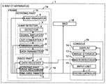
- FIG. 1is a block diagram illustrating the configuration of an X-ray CT apparatus according to an embodiment
- FIG. 3is a schematic diagram illustrating the internal structure of an X-ray detector of the embodiment
- FIG. 4is another schematic diagram illustrating the internal structure of the X-ray detector of the embodiment.
- FIG. 5is a flowchart of the operation of the X-ray CT apparatus of the embodiment.
- FIG. 6Ais a schematic diagram illustrating the internal structure of an X-ray detector according to a first comparative example of the embodiment.
- FIG. 6Bis a schematic diagram illustrating the internal structure of an X-ray detector according to a second comparative example of the embodiment.
- an X-ray CT apparatusincludes a fixed part, a rotating part, a detector, an analog-to-digital (A/D) converter, a data transmitter, and a wireless transceiver.
- the rotating partis configured to be rotatably attached to the fixed part to rotate around a subject.
- the detectoris arranged in the rotating part, and detects X-rays emitted from an irradiator and generates an analog signal.
- the A/D converteris arranged in the rotating part, and converts the analog signal to a digital signal.
- the data transmitteris arranged in the rotating part, and, upon receipt of the digital signal from the A/D converter, transmits the digital signal to a data receiver arranged in the fixed part.
- the wireless transceiverwirelessly transmits and receives signals in at least a part between the detector and the A/D converter or between the A/D converter and the data transmitter.
- FIG. 1is a block diagram of an X-ray CT apparatus 1 according to an embodiment.
- the X-ray CT apparatus 1 of the embodimentincludes a frame 1 a , a console 1 b , and a bed 16 .
- the frame 1 aincludes a rotating part 1 c and a fixed part 1 d .
- the fixed part 1 dis connected to, for example, an external power source (not illustrated), and supplies power and signals to parts constituting the rotating part 1 c via a power/signal supply unit such as a slip ring.
- the rotating part 1 cincludes an X-ray irradiator 4 , an X-ray detector 5 , and a data transmitter 10 , and is rotatably attached to the fixed part 1 d .
- FIG. 2is a perspective view of the X-ray CT apparatus 1 of the embodiment.
- Z-axisis an axis extending along the body axis of a patient (subject) placed on the bed 16
- Y-axisis an axis extending in the vertical directions
- X-axisis an axis extending perpendicular to the Z-axis and the Y-axis.
- the system controller 2notifies the frame control transmitter 3 of a control content for the X-ray irradiator 4 , a transmission controller 9 , the data receiver 11 , and the rotating-part drive mechanism 17 .
- the system controller 2displays a predetermined input screen on the display 14 at a predetermined timing. According to an instruction from the operator provided through the input unit 15 or at a predetermined timing, the system controller 2 displays an image on the display 14 based on image data stored in the image storage 13 .
- the system controller 2notifies the image reconstruction unit 12 of a control content for the transmission controller 9 .
- the system controller 2moves the bed 16 according to an instruction from the operator provided through the input unit 15 to move the position of a patient placed thereon.
- the X-ray detector 5includes a detector 6 , a signal amplifier 7 , an A/D converter 8 , and the transmission controller 9 .
- the X-ray detector 5is irradiated with X-rays by the X-ray irradiator 4 , and detects X-rays having passed through the patient placed on the bed 16 with the detector 6 .
- the detector 6generates analog signals based on the intensity of the X-rays detected and transmits the analog signals to the signal amplifier 7 .
- the signal amplifier 7amplifies the analog signals received from the detector 6 , and transmits them to the A/D converter 8 .
- the A/D converter 8converts the analog signals having been amplified and received from the signal amplifier 7 to digital signals, and transmits the digital signals to the transmission controller 9 .
- the transmission controller 9transmits the digital signals received from the A/D converter 8 to the data transmitter 10 according to the control content received from the frame control transmitter 3 .
- the configuration of the X-ray detector 5is described in detail later.
- the data transmitter 10transmits the digital signals received from the transmission controller 9 to the data receiver 11 using a communication means such as, for example, optical communication.
- the image reconstruction unit 12According to an instruction from the system controller 2 , the image reconstruction unit 12 generates image data based on the digital signals received from the data receiver 11 , and transmits the image data to the image storage 13 .
- the image storage 13stores the image data received from the image reconstruction unit 12 .
- the display 14displays an image based on the image data stored in the image storage 13 . Besides, according to an instruction from the system controller 2 , the display 14 displays a predetermined input screen.
- the input unit 15includes, for example, a mouse, a track ball, and a keyboard, and issues an instruction to the system controller 2 according to an input provided by the operator.
- the bed 16operates according to an instruction from the system controller 2 to move the position of the patient placed thereon in the directions of the X axis, the Y axis, and the Z axis.
- the rotating-part drive mechanism 17operates according to an instruction from the frame control transmitter 3 , and rotates the rotating part 1 c . In addition, according to an instruction from the frame control transmitter 3 , the rotating-part drive mechanism 17 stops the rotation of the rotating part 1 c.
- the configuration of the X-ray detector 5is described in detail below.
- FIGS. 3 and 4are schematic views illustrating the internal structure of the X-ray detector 5 of the embodiment.
- FIG. 3schematically illustrates an example of a cross-sectional view taken along a section line extending in the column direction.
- the horizontal directionindicates the column direction that corresponds to the Z-axis direction in FIG. 2
- the vertical directionindicates the Y-axis direction in FIG. 2 .
- the direction perpendicular to the paper surfaceindicates a channel direction that corresponds to the direction of the curvature of the detection surface of the X-ray detector 5 .
- the column directionmay be opposite to that indicated in FIG. 3 .
- the X-ray detector 5includes scintillators 21 , photodiode chips 22 , DAS chips 23 , substrates 24 , data-transfer radio-wave transmitters 25 , shields 26 , power-supply radio-wave receivers 27 , storage batteries 28 , a backplane 29 , data-transfer radio-wave receivers 30 , power-supply radio-wave transmitters 31 , and positioning pins 32 .
- the X-ray detector 5is inserted in a housing 20 in, for example, the direction indicated by arrow A (Z-axis direction) at the time of the manufacture or maintenance to be installed therein.
- the scintillators 21 and the photodiode chips 22correspond to, for example, the detector 6 in FIG. 1 .
- the DAS chips 23correspond to, for example, the signal amplifier 7 , the A/D converter 8 , and the transmission controller 9 in FIG. 1 .
- the data-transfer radio-wave transmitter 25faces the data-transfer radio-wave receiver 30
- the power-supply radio-wave receiver 27faces the power-supply radio-wave transmitter 31 .
- the distance between the data-transfer radio-wave transmitter 25 and the data-transfer radio-wave receiver 30 , and the distance between the power-supply radio-wave receiver 27 and the power-supply radio-wave transmitter 31are determined by, for example, the length of the positioning pin 32 or the depth of the recess. Note that although FIG. 3 illustrates an example in which the positioning pin 32 is arranged on the backplane 29 and the recess is formed in the substrate 24 , the positioning pin 32 may be arranged on the substrate 24 and the recess may be formed in the backplane 29 .
- the X-ray detector 5is provided with the scintillator 21 , the photodiode chip 22 , the DAS chip 23 , the substrate 24 , the data-transfer radio-wave transmitter 25 , the shield 26 , the power-supply radio-wave receiver 27 , the storage battery 28 , the data-transfer radio-wave receiver 30 , the power-supply radio-wave transmitter 31 , and the positioning pin 32 , for example, in units of modules 41 , which are divided in at least the body axis direction of the subject as illustrated in FIG. 4 .
- the X-ray detector 5includes, for example, four arrays of 38 (4 ⁇ 38) modules, in which arrays of four modules are arranged in the column direction, and arrays of 38 modules are arranged in the channel direction.
- the column directioncorresponds to the Z-axis direction in FIG. 2
- the channel directioncorresponds to the curvature direction of the detection surface of the X-ray detector 5 .
- X-rays emitted from the X-ray irradiator 4are collimated by a collimator (not illustrated), and then incident on the scintillator 21 .
- the scintillator 21converts the incident X-rays into light.
- the light generated in the scintillator 21is incident on the photodiode chip 22 .
- the photodiode chip 22includes, for example, (64 ⁇ 24) photodiode elements (detector elements), in which arrays of 64 photodiode elements are arranged in the column direction, and arrays of 24 photodiode elements are arranged in the channel direction.
- the photodiode chip 22generates analog signals based on the incident light in units of photodiode elements.
- the photodiode chip 22transmits the analog signals to the DAS chip 23 by differentiating them in units of photodiode elements.
- the data-transfer radio-wave transmitter 25is a wireless communication unit (wireless transceiver, wireless communication part, wireless communication circuit), and converts the digital signals received from the DAS chip 23 into radio waves of a predetermined frequency using electrical energy stored in the storage battery 28 .
- the data-transfer radio-wave transmitter 25transmits the radio waves to the data-transfer radio-wave receiver 30 in serial, for example, in units of arrays of photodiode elements of the modules 41 .
- the shield 26has, for example, radio-wave shielding function.
- the shield 26guides the radio waves transmitted from the data-transfer radio-wave transmitter 25 to the corresponding data-transfer radio-wave receiver 30 such that the radio waves are exchanged only between the data-transfer radio-wave transmitter 25 and the data-transfer radio-wave receiver 30 in a corresponding relationship so as not to affect the other modules 41 .
- the corresponding relationship as used hereinindicates the constituent elements of the same module 41 .
- the shield 26guides the radio wave transmitted from the power-supply radio-wave transmitter 31 to the corresponding power-supply radio-wave receiver 27 such that the radio wave is exchanged only between the power-supply radio-wave transmitter 31 and the power-supply radio-wave receiver 27 in a corresponding relationship so as not to affect the other modules 41 .
- the data-transfer radio-wave receiver 30is a wireless communication unit (wireless transceiver, wireless communication part, wireless communication circuit), and generates digital signals based on the radio waves transmitted from the data-transfer radio-wave transmitter 25 and guided by the shield 26 .
- the data-transfer radio-wave receiver 30transmits the digital signals to the data transmitter 10 .
- the power-supply radio-wave transmitter 31is a wireless power supply unit (radio power supply), and converts a current supplied from the fixed part 1 d into a radio wave.
- the power-supply radio-wave transmitter 31transmits the radio wave to the power-supply radio-wave receiver 27 .
- the power-supply radio-wave receiver 27is a wireless power supply unit (radio power supply), and converts the radio wave transmitted from the power-supply radio-wave transmitter 31 and guided by the shield 26 into a current.
- the power-supply radio-wave receiver 27sends the current to the storage battery 28 .
- the storage battery 28is charged by the current fed from the power-supply radio-wave receiver 27 , and stores electrical energy.
- the storage battery 28supplies the electrical energy stored therein to the data-transfer radio-wave transmitter 25 .
- step S 2the system controller 2 displays a predetermined input screen on the display 14 .
- the display 14displays a predetermined input screen thereon.
- the predetermined input screenis used to set, for example, the intensity of X-rays, the irradiation range of X-rays, the irradiation time of X-rays, the rotational speed of the rotating part 1 c , and the like, each of which is related to imaging.
- the operatorprovides an input to the input screen using the input unit 15 .
- the operatorplaces the patient on the bed 16 , and enters an instruction by using the input unit 15 to move the position of the patient to the imaging position.
- the system controller 2moves the position of the patient to the imaging position.
- the processproceeds to step S 3 .
- X-rays emitted from the X-ray irradiator 4are collimated by a collimator (not illustrated), and then incident on the scintillator 21 .
- the scintillator 21converts the incident X-rays into light.
- the light generated in the scintillator 21is incident on the photodiode chip 22 .
- the photodiode chip 22generates analog signals based on the incident light in units of photodiode elements.
- the photodiode chip 22transmits the analog signals to the DAS chip 23 by differentiating them.
- the DAS chip 23amplifies the analog signals received from the photodiode chip 22 in units of photodiode elements.
- the DAS chip 23then converts the analog signals into digital signals in units of photodiode elements. According to the control content received from the frame control transmitter 3 , the DAS chip 23 transmits the digital signals to the data-transfer radio-wave transmitter 25 .
- the data-transfer radio-wave transmitter 25converts the digital signals received from the DAS chip 23 into radio waves of a predetermined frequency using the electrical energy accumulated in the storage battery 28 from step S 1 .
- the data-transfer radio-wave transmitter 25transmits the radio waves to the data-transfer radio-wave receiver 30 .
- the shield 26guides the radio waves transmitted from the data-transfer radio-wave transmitter 25 to the corresponding data-transfer radio-wave receiver 30 such that the radio waves are exchanged only between the data-transfer radio-wave transmitter 25 and the data-transfer radio-wave receiver 30 in a corresponding relationship.
- the data-transfer radio-wave receiver 30generates digital signals based on the radio waves transmitted from the data-transfer radio-wave transmitter 25 and guided by the shield 26 .
- the data-transfer radio-wave receiver 30transmits the digital signals to the data transmitter 10 .
- the data transmitter 10transmits the digital signals received from the data-transfer radio-wave receiver 30 to the data receiver 11 using a communication means such as, for example, optical communication.
- the data receiver 11transmits the digital signals received from the data transmitter 10 to the image reconstruction unit 12 in the console 1 b .
- the processproceeds to step S 5 .
- step S 5the system controller 2 notifies the frame control transmitter 3 of a control content for stopping the irradiation of X-rays.
- the frame control transmitter 3transmits the notification from the system controller 2 to the X-ray irradiator 4 .
- the X-ray irradiator 4stops irradiating X-rays.
- the system controller 2notifies the frame control transmitter 3 of a control content for stopping the rotation of the rotating part 1 c .
- the frame control transmitter 3transmits the notification from the system controller 2 to the rotating-part drive mechanism 17 .
- the rotating-part drive mechanism 17operates according to the control content received from the frame control transmitter 3 and stops the rotation of the rotating part 1 c .
- the image reconstruction unit 12generates image data based on the digital signals received from the data receiver 11 and transmits the image data to the image storage 13 .
- the image storage 13stores the image data received from the image reconstruction unit 12 .
- the system controller 2displays an image on the display 14 based on the image data stored in the image storage 13 .
- the display 14displays the image based on the image data stored in the image storage 13 .
- step S 6the operator refers to the image displayed on the display 14 . Having finished referring to the image, the operator ends the operation of the X-ray CT apparatus 1 .
- the X-ray CT apparatus 1wirelessly transmits signals inside the X-ray detector 5 .
- FIG. 6Ais a schematic diagram illustrating an X-ray detector, which transmits signals by only wired communication, in a first comparative example of this embodiment.
- a connector top 34is fixed to the substrate 24
- a connector bottom 35is fixed to the backplane 29 .
- the connector top 34is connected to the connector bottom 35 only when the position of the positioning pin 32 matches the position of the recess in the substrate 24 .
- a digital signal from the DAS chip 23is transmitted via the connector top 34 and the connector bottom 35 to the data transmitter.
- the connector top 34 and the connector bottom 35include a plurality of pins for signal transmission, the number of which corresponds to the number of elements of one module, for example.
- the connector top 34cannot be connected to the connector bottom 35 , thereby possibly causing a defect in the product.
- signalsare transmitted wirelessly in this portion.
- FIG. 6Bis a schematic diagram illustrating another X-ray detector, which transmits data by only wired communication, in a second comparative example of this embodiment.
- the X-ray detector of the second comparative example as illustrated in FIG. 6Bfor example, one end of FPC 33 is fixed to the substrate 24 , and the other end of the FPC 33 is fixed to the connector top 34 .
- the connector bottom 35is fixed to the backplane 29 .
- the connector top 34 and the connector bottom 35 located on the opening side B of the housing 20are easy to be connected together in, for example, the manufacture or maintenance.
- the connector top 34 and the connector bottom 35 located on the inner side C of the housing 20are difficult to be connected together.
- signalsare transmitted wirelessly in this portion.
- the signal transmissioncan be carried out, and product defects are less likely to occur.
- these partsdo not need to be physically connected, which facilitates the installation of the X-ray detector 5 in the housing 20 .
- noise due to the vibration of the FPC and the connectorcan be reduced while the X-ray CT apparatus is in operation.
- a wireless communication unit of a second modulewhich is adjacent to the first module in the body axis direction of the subject, wirelessly transmits and receives signals at a second frequency that is different from the first frequency.
- signalscan be prevented from being wrongly transmitted and received between the data-transfer radio-wave transmitter 25 and the data-transfer radio-wave receiver 30 not in a corresponding relationship.
- a wireless communication unit of a second modulewhich is adjacent to the first module in the body axis direction of the subject, wirelessly transmits and receives signals at a second timing that is different from the first timing.
- signalscan be prevented from being wrongly transmitted and received between the data-transfer radio-wave transmitter 25 and the data-transfer radio-wave receiver 30 not in a corresponding relationship.
- the data-transfer radio-wave transmitter 25transmits and receives radio waves in all the modules.
- at least one of the modulesmay include a wired communication unit (wired communication circuit) that transmits and receives signals via wire in at least a part between the detector 6 and the A/D converter 8 or between the A/D converter 8 and the data transmitter 10 . That is, a first module of the plurality of modules that are divided in the Z-axis direction wirelessly transmits and receives signals through the wireless communication unit. Besides, a second module, which is different from the first module, transmits and receives signals via wire through the wired communication unit. The second module is located at the end of the modules.
- the connectorscan be easily connected to each other at the end.
- the inner side Cit is difficult to connect the connectors of the modules near the center at a distance from the end. Therefore, if signals are transmitted and received wirelessly in the part where connectors are difficult to be connected, a manufacturing defect is less likely to occur.
- signalsare converted into radio waves, and transmitted and received wirelessly in a part between the A/D converter 8 and the data transmitter 10 .
- Signalsmay be converted into radio waves, and transmitted and received wirelessly in at least a part between the detector 6 and the A/D converter 8 (e.g., between the detector 6 and the signal amplifier 7 or between the signal amplifier 7 and the A/D converter 8 ), between the detector 6 and the A/D converter 8 , between the A/D converter 8 and the transmission controller 9 , or between the transmission controller 9 and the data transmitter 10 .
- the wireless communication unitmay transmit and receive signals by optical communication using light.
- Electric poweris supplied wirelessly in a part between the A/D converter 8 and the data transmitter 10 .
- Electric powermay be supplied wirelessly in a part between the detector 6 and the A/D converter 8 (e.g., between the detector 6 and the signal amplifier 7 or between the signal amplifier 7 and the A/D converter 8 ).
- a currentis converted into a radio wave, and electric power is supplied based on the transmission and reception of the radio wave, it is not so limited, and the use of non-contact power transmission may suffice.
- electric powermay be supplied using electromagnetic induction between coils arranged at positions corresponding to the power-supply radio-wave transmitter 31 and the power-supply radio-wave receiver 27 .
- electric powermay be supplied by using so-called electromagnetic resonance method that utilizes the resonance of an electromagnetic field.
- At least an array of four modules arranged in the column directionmay be installed as one unit.
- the modulesmay be installed separately.
- the number of modules in one unitcan be arbitrarily determined, and, for example, two modules may be set as one unit.
- each moduleis provided with the positioning pin 32 .
- the positioning pin 32need not necessarily be provided to all the modules. For example, when one unit is made up of four modules, only two modules at both ends may be provided with the positioning pin 32 , and remaining two may be provided with no positioning pin.
- the X-ray detector 5includes modules which are divided in the column and channel directions.
- the X-ray detector 5may include a plurality of modules which are divided in only the channel direction.
- a plurality of modulesmay constitute only the center part of the X-ray detector 5 but the edges in the column and channel directions.
- the X-ray detector of the embodimentmay be applied to a medical imaging apparatus that uses a variety of X-ray detectors such as an X-ray imaging apparatus provided with an X-ray tube at one end of the C-shaped arm and an X-ray detector at the other end.
Landscapes
- Health & Medical Sciences (AREA)
- Life Sciences & Earth Sciences (AREA)
- Engineering & Computer Science (AREA)
- Medical Informatics (AREA)
- Physics & Mathematics (AREA)
- Molecular Biology (AREA)
- High Energy & Nuclear Physics (AREA)
- Heart & Thoracic Surgery (AREA)
- General Health & Medical Sciences (AREA)
- Pathology (AREA)
- Radiology & Medical Imaging (AREA)
- Biomedical Technology (AREA)
- Nuclear Medicine, Radiotherapy & Molecular Imaging (AREA)
- Biophysics (AREA)
- Surgery (AREA)
- Animal Behavior & Ethology (AREA)
- Optics & Photonics (AREA)
- Public Health (AREA)
- Veterinary Medicine (AREA)
- Computer Networks & Wireless Communication (AREA)
- General Physics & Mathematics (AREA)
- Spectroscopy & Molecular Physics (AREA)
- Mathematical Physics (AREA)
- Pulmonology (AREA)
- Theoretical Computer Science (AREA)
- Apparatus For Radiation Diagnosis (AREA)
- Measurement Of Radiation (AREA)
Abstract
Description
Claims (8)
Applications Claiming Priority (3)
| Application Number | Priority Date | Filing Date | Title |
|---|---|---|---|
| JP2013112143AJP2014230600A (en) | 2013-05-28 | 2013-05-28 | X-ray ct apparatus, and x-ray detector for x-ray ct apparatus |
| JP2013-112143 | 2013-05-28 | ||
| PCT/JP2014/061515WO2014192471A1 (en) | 2013-05-28 | 2014-04-24 | X-ray ct device and x-ray detector |
Related Parent Applications (1)
| Application Number | Title | Priority Date | Filing Date |
|---|---|---|---|
| PCT/JP2014/061515ContinuationWO2014192471A1 (en) | 2013-05-28 | 2014-04-24 | X-ray ct device and x-ray detector |
Publications (2)
| Publication Number | Publication Date |
|---|---|
| US20160066876A1 US20160066876A1 (en) | 2016-03-10 |
| US10588593B2true US10588593B2 (en) | 2020-03-17 |
Family
ID=51988510
Family Applications (1)
| Application Number | Title | Priority Date | Filing Date |
|---|---|---|---|
| US14/941,952Active2036-12-24US10588593B2 (en) | 2013-05-28 | 2015-11-16 | X-ray CT apparatus and X-ray detector |
Country Status (3)
| Country | Link |
|---|---|
| US (1) | US10588593B2 (en) |
| JP (1) | JP2014230600A (en) |
| WO (1) | WO2014192471A1 (en) |
Cited By (1)
| Publication number | Priority date | Publication date | Assignee | Title |
|---|---|---|---|---|
| US11166685B2 (en)* | 2018-08-03 | 2021-11-09 | Canon Medical Systems Corporation | Radiation detector and radiation detector module |
Families Citing this family (7)
| Publication number | Priority date | Publication date | Assignee | Title |
|---|---|---|---|---|
| JPWO2016140021A1 (en)* | 2015-03-05 | 2017-12-14 | 三井金属鉱業株式会社 | Ceramic cylindrical target material and cylindrical sputtering target |
| EP3234950B1 (en)* | 2015-10-30 | 2022-07-13 | Shanghai United Imaging Healthcare Co., Ltd. | Anti-scatter grid for radiation detector |
| JP6643104B2 (en)* | 2016-01-22 | 2020-02-12 | キヤノン株式会社 | Radiation imaging apparatus, control method of radiation imaging apparatus, radiation imaging system |
| KR20180090618A (en)* | 2017-02-03 | 2018-08-13 | 삼성전자주식회사 | X-ray detector |
| JP7269823B2 (en)* | 2019-08-07 | 2023-05-09 | キヤノンメディカルシステムズ株式会社 | X-ray CT device |
| CN112260764B (en)* | 2020-10-19 | 2022-04-01 | 中国核动力研究设计院 | Communication system and method based on rotary radioactive source |
| EP4289360A4 (en)* | 2021-03-11 | 2025-01-01 | National University Corporation Shizuoka University | RADIATION IMAGING DEVICE |
Citations (85)
| Publication number | Priority date | Publication date | Assignee | Title |
|---|---|---|---|---|
| US5530424A (en)* | 1994-09-16 | 1996-06-25 | General Electric Company | Apparatus and method for high data rate communication in a computerized tomography system |
| US5912942A (en)* | 1997-06-06 | 1999-06-15 | Schick Technologies, Inc. | X-ray detection system using active pixel sensors |
| US5991358A (en)* | 1997-12-31 | 1999-11-23 | Analogic Corporation | Data acquisition system for generating accurate projection data in a CT scanner |
| US6081576A (en)* | 1998-08-25 | 2000-06-27 | General Electric Company | Scalable data acquisition system |
| US6198791B1 (en)* | 1998-08-25 | 2001-03-06 | General Electric Company | Scalable multislice imaging system |
| US6292919B1 (en)* | 1998-08-25 | 2001-09-18 | General Electric Company | Methods and apparatus for exchanging data in an imaging system |
| US6292528B1 (en)* | 1998-10-28 | 2001-09-18 | U.S. Philips Corporation | Computer tomograph detector |
| US6972411B2 (en)* | 2002-10-03 | 2005-12-06 | Schick Technologies, Inc. | Method of event detection for intraoral image sensor |
| US7015478B2 (en)* | 2002-11-27 | 2006-03-21 | Canon Kabushiki Kaisha | X-ray imaging apparatus |
| US7072443B2 (en)* | 2002-10-03 | 2006-07-04 | Schick Technologies, Inc. | Intraoral image sensor |
| US7421063B2 (en)* | 2006-06-26 | 2008-09-02 | Canon Kabushiki Kaisha | Radiation imaging apparatus, radiation imaging system, and method of controlling radiation imaging apparatus |
| US7545914B2 (en)* | 2007-07-27 | 2009-06-09 | Fujifilm Corporation | Radiation image capturing system |
| US7561668B2 (en)* | 2007-08-09 | 2009-07-14 | Fujifilm Corporation | Radiation detecting cassette and radiation image capturing system |
| US7593507B2 (en)* | 2007-08-16 | 2009-09-22 | Fujifilm Corporation | Radiation image capturing system and method of setting minimum transmission radio-field intensity in such radiation image capturing system |
| US7638773B2 (en)* | 2007-07-23 | 2009-12-29 | Fujifilm Corporation | Cassette |
| US7655916B2 (en)* | 2007-08-10 | 2010-02-02 | Fujifilm Corporation | Radiation image capturing system |
| US20100080360A1 (en) | 2008-09-26 | 2010-04-01 | Fujifilm Corporation | Radiographic imaging table |
| US7712959B2 (en)* | 2007-08-23 | 2010-05-11 | Fujifilm Corporation | Bed for capturing radiation image and radiation image capturing system |
| US7732779B2 (en)* | 2007-09-27 | 2010-06-08 | Fujifilm Corporation | Radiation imaging apparatus |
| US7737427B2 (en)* | 2007-07-30 | 2010-06-15 | Fujifilm Corporation | Radiation image capturing system |
| US7740405B2 (en)* | 2007-08-20 | 2010-06-22 | Fujifilm Corporation | Cassette |
| US7767981B2 (en)* | 2007-07-30 | 2010-08-03 | Fujifilm Corporation | Radiation detecting cassette and medical system |
| US7772560B2 (en)* | 2007-08-16 | 2010-08-10 | Fujifilm Corporation | Radiation detecting cassette and radiation image capturing system |
| US7777192B2 (en)* | 2007-09-05 | 2010-08-17 | Fujifilm Corporation | Cassette system |
| US7777193B2 (en)* | 2007-09-28 | 2010-08-17 | Fujifilm Corporation | Radiation imaging apparatus |
| US7787594B2 (en)* | 2007-07-26 | 2010-08-31 | Fujifilm Corporation | Radiation image capturing method, radiation image capturing system and radiation information system for carrying out radiation image capturing method |
| US7807976B2 (en)* | 2008-02-29 | 2010-10-05 | Fujifilm Corporation | Radiation image detection apparatus and radiation image photographing system |
| US7829859B2 (en)* | 2007-07-27 | 2010-11-09 | Fujifilm Corporation | Radiation detecting cassette and radiation image capturing system |
| US7834322B2 (en)* | 2007-07-27 | 2010-11-16 | Fujifilm Corporation | Radiation image capturing system |
| US7847277B2 (en)* | 2007-07-30 | 2010-12-07 | Fujifilm Corporation | Radiation image capturing system |
| US7888649B2 (en)* | 2007-07-06 | 2011-02-15 | Fujifilm Corporation | Radiation image capturing system |
| US7894575B2 (en)* | 2008-09-29 | 2011-02-22 | Fujifilm Corporation | Radiation image capturing system |
| US7935931B2 (en)* | 2007-08-10 | 2011-05-03 | Fujifilm Corporation | Radiation image capturing system |
| US7991119B2 (en)* | 2008-12-12 | 2011-08-02 | Fujifilm Corporation | Radiation detecting apparatus, radiographic image capturing system, and radiographic image capturing method |
| US7999234B2 (en)* | 2008-01-29 | 2011-08-16 | Fujifilm Corporation | Cradle for use with radiation conversion device |
| US8050383B2 (en)* | 2008-09-02 | 2011-11-01 | Fujifilm Corporation | Radiographic apparatus and radiographic method |
| US8053727B2 (en)* | 2008-01-31 | 2011-11-08 | Fujifilm Corporation | Radiation conversion device and radiation image capturing system using the same |
| JP2011226902A (en) | 2010-04-20 | 2011-11-10 | Nec Tohoku Ltd | X-ray data acquisition device |
| US8080802B2 (en)* | 2008-12-26 | 2011-12-20 | Fujifilm Corporation | Radiation detecting apparatus, radiographic image capturing system, and radiographic image capturing method |
| US8112000B2 (en)* | 2008-01-30 | 2012-02-07 | Fujifilm Corporation | Electronic device |
| US8182147B2 (en)* | 2008-12-01 | 2012-05-22 | Fujifilm Corporation | Portable radiographic imaging device and radiographic imaging system |
| US8203446B2 (en)* | 2008-09-30 | 2012-06-19 | Fujifilm Corporation | Radio communication terminal |
| US8229202B2 (en)* | 2007-09-27 | 2012-07-24 | Fujifilm Corporation | Radiation imaging apparatus |
| US8259904B2 (en)* | 2009-03-19 | 2012-09-04 | Fujifilm Corporation | Radiographic image capturing system, radiation converter, processor, selector for selecting radiation converter and processor, program, method of selecting radiation converter and processor, and radiographic image capturing method |
| US8265225B2 (en)* | 2009-02-12 | 2012-09-11 | Fujifilm Corporation | Radiation imaging system, power supplying apparatus, charging apparatus, and radiation imaging method |
| US8270564B2 (en)* | 2008-12-01 | 2012-09-18 | Teratech Corporation | Digital integration with detector correction |
| JP2012187144A (en) | 2011-03-08 | 2012-10-04 | Toshiba Corp | Non-contact signal transmitting device, and x-ray ct apparatus |
| US8330597B2 (en)* | 2008-01-28 | 2012-12-11 | Fujifilm Corporation | Radiation detection apparatus and radiation image capturing system |
| US8334515B2 (en)* | 2008-12-08 | 2012-12-18 | Fujifilm Corporation | Radiation detecting apparatus, radiographic image capturing system, and radiographic image capturing method |
| US8334516B2 (en)* | 2009-03-24 | 2012-12-18 | Fujifilm Corporation | Radiation detecting apparatus, radiographic image capturing system, and radiographic image capturing method |
| US8357908B2 (en)* | 2007-07-27 | 2013-01-22 | Fujifilm Corporation | Radiation detecting cassette and radiation image picking-up system |
| US8378309B2 (en)* | 2010-10-19 | 2013-02-19 | Fujifilm Corporation | Radiation detector, radiographic image capturing system, radiation detection method, radiation detection program storage medium, and controller |
| US8421024B2 (en)* | 2008-01-28 | 2013-04-16 | Fujifilm Corporation | Cradle for use with radiation conversion device |
| US8451974B2 (en)* | 2003-04-25 | 2013-05-28 | Rapiscan Systems, Inc. | X-ray tomographic inspection system for the identification of specific target items |
| US8532262B2 (en)* | 2010-03-17 | 2013-09-10 | Fujifilm Corporation | Radiographic image capturing system |
| US8546777B2 (en)* | 2010-03-12 | 2013-10-01 | Fujifilm Corporation | Radiographic image capturing device |
| US8552392B2 (en)* | 2007-07-27 | 2013-10-08 | Fujifilm Corporation | Cassette and radiation image capturing system |
| US8654926B2 (en)* | 2008-12-12 | 2014-02-18 | Fujifilm Corporation | Radiation detecting apparatus, radiographic image capturing system, and radiographic image capturing method |
| US8675624B2 (en)* | 2009-11-13 | 2014-03-18 | Canon Kabushiki Kaisha | Radiation imaging system, method for radiation imaging system, and computer-readable storage medium |
| US8837669B2 (en)* | 2003-04-25 | 2014-09-16 | Rapiscan Systems, Inc. | X-ray scanning system |
| US8861678B2 (en)* | 2012-05-11 | 2014-10-14 | General Electric Company | Power and communication interface between a digital X-ray detector and an X-ray imaging system |
| US8885795B2 (en)* | 2010-10-14 | 2014-11-11 | Fujifilm Corporation | Radiation detector, radiographic image capturing system, radiation detection method, and radiation detection program storage medium |
| US8891733B2 (en)* | 2012-05-11 | 2014-11-18 | General Electric Company | Power and communication interface between a digital X-ray detector and an X-ray imaging system |
| US9111379B2 (en)* | 2012-06-28 | 2015-08-18 | Mobius Imaging, Llc | Method and system for X-ray CT imaging |
| US9125613B2 (en)* | 2012-06-12 | 2015-09-08 | Mobius Imaging, Llc | Detector system for imaging device |
| US9138195B2 (en)* | 2012-04-23 | 2015-09-22 | Analogic Corporation | Contactless communication signal transfer |
| US9380988B2 (en)* | 2013-02-12 | 2016-07-05 | Fujifilm Corporation | Electronic cassette for radiographic imaging |
| US9492137B2 (en)* | 2013-09-17 | 2016-11-15 | Fujifilm Corporation | Portable radiographic imaging apparatus and system |
| US9538107B2 (en)* | 2013-05-16 | 2017-01-03 | Koninklijke Philips N.V. | Imaging detector |
| US9536302B2 (en)* | 2012-03-06 | 2017-01-03 | Toshiba Medical Systems Corporation | Image processing apparatus, X-ray radiographic apparatus, and image processing method |
| US9532759B2 (en)* | 2012-08-30 | 2017-01-03 | Toshiba Medical Systems Corporation | X-ray CT apparatus, image processing apparatus, and image processing method |
| US9538978B2 (en)* | 2013-09-17 | 2017-01-10 | Fujifilm Corporation | Radiographic imaging system and access controller for communication access |
| US9585625B2 (en)* | 2007-09-25 | 2017-03-07 | Shimadzu Corporation | Radiographic apparatus |
| US9595101B2 (en)* | 2012-12-19 | 2017-03-14 | Toshiba Medical Systems Corporation | X-ray CT apparatus, image processing apparatus, and image processing method |
| US9655567B2 (en)* | 2009-02-06 | 2017-05-23 | Toshiba Medical Systems Corporation | Radiation diagnostic apparatus, X-ray computed tomography apparatus, and image processing method |
| US9681850B2 (en)* | 2013-08-27 | 2017-06-20 | Samsung Electronics Co., Ltd. | Method and apparatus for managing X-ray accumulation amount |
| US9689996B2 (en)* | 2013-04-05 | 2017-06-27 | General Electric Company | Integrated diode DAS detector |
| US9808159B2 (en)* | 2013-05-08 | 2017-11-07 | Makoto Shizukuishi | Solid-state image sensor and imaging apparatus including the same |
| US9810793B2 (en)* | 2012-11-27 | 2017-11-07 | Toshiba Medical Systems Corporation | X-ray CT apparatus and data detection system for X-ray CT apparatus |
| US9818182B2 (en)* | 2012-06-20 | 2017-11-14 | Hitachi, Ltd. | X-ray CT device |
| US9968323B2 (en)* | 2012-12-21 | 2018-05-15 | Toshiba Medical Systems Corporation | X-ray computed tomography apparatus |
| US10022100B2 (en)* | 2013-01-24 | 2018-07-17 | Toshiba Medical Systems Corporation | Medical image diagnostic apparatus, medical image processing apparatus, medical image processing method and gantry moving position determination method |
| US10217246B2 (en)* | 2012-12-28 | 2019-02-26 | Toshiba Medical Systems Corporation | X-ray computed tomography apparatus and control method |
| US10258296B2 (en)* | 2013-05-23 | 2019-04-16 | Toshiba Medical Systems Corporation | X-ray CT apparatus including processing circuitry to improve a spatial resolution in a row direction and a channel direction |
| US10357214B2 (en)* | 2013-04-26 | 2019-07-23 | Toshiba Medical Systems Corporation | Photon counting CT apparatus, light detection device, radiation detection device, and radiation analysis device |
- 2013
- 2013-05-28JPJP2013112143Apatent/JP2014230600A/enactivePending
- 2014
- 2014-04-24WOPCT/JP2014/061515patent/WO2014192471A1/ennot_activeCeased
- 2015
- 2015-11-16USUS14/941,952patent/US10588593B2/enactiveActive
Patent Citations (87)
| Publication number | Priority date | Publication date | Assignee | Title |
|---|---|---|---|---|
| US5530424A (en)* | 1994-09-16 | 1996-06-25 | General Electric Company | Apparatus and method for high data rate communication in a computerized tomography system |
| US5912942A (en)* | 1997-06-06 | 1999-06-15 | Schick Technologies, Inc. | X-ray detection system using active pixel sensors |
| US5991358A (en)* | 1997-12-31 | 1999-11-23 | Analogic Corporation | Data acquisition system for generating accurate projection data in a CT scanner |
| US6081576A (en)* | 1998-08-25 | 2000-06-27 | General Electric Company | Scalable data acquisition system |
| US6198791B1 (en)* | 1998-08-25 | 2001-03-06 | General Electric Company | Scalable multislice imaging system |
| US6292919B1 (en)* | 1998-08-25 | 2001-09-18 | General Electric Company | Methods and apparatus for exchanging data in an imaging system |
| US6292528B1 (en)* | 1998-10-28 | 2001-09-18 | U.S. Philips Corporation | Computer tomograph detector |
| US6972411B2 (en)* | 2002-10-03 | 2005-12-06 | Schick Technologies, Inc. | Method of event detection for intraoral image sensor |
| US7072443B2 (en)* | 2002-10-03 | 2006-07-04 | Schick Technologies, Inc. | Intraoral image sensor |
| US7015478B2 (en)* | 2002-11-27 | 2006-03-21 | Canon Kabushiki Kaisha | X-ray imaging apparatus |
| US8451974B2 (en)* | 2003-04-25 | 2013-05-28 | Rapiscan Systems, Inc. | X-ray tomographic inspection system for the identification of specific target items |
| US8837669B2 (en)* | 2003-04-25 | 2014-09-16 | Rapiscan Systems, Inc. | X-ray scanning system |
| US7421063B2 (en)* | 2006-06-26 | 2008-09-02 | Canon Kabushiki Kaisha | Radiation imaging apparatus, radiation imaging system, and method of controlling radiation imaging apparatus |
| US7888649B2 (en)* | 2007-07-06 | 2011-02-15 | Fujifilm Corporation | Radiation image capturing system |
| US7638773B2 (en)* | 2007-07-23 | 2009-12-29 | Fujifilm Corporation | Cassette |
| US7787594B2 (en)* | 2007-07-26 | 2010-08-31 | Fujifilm Corporation | Radiation image capturing method, radiation image capturing system and radiation information system for carrying out radiation image capturing method |
| US7545914B2 (en)* | 2007-07-27 | 2009-06-09 | Fujifilm Corporation | Radiation image capturing system |
| US8357908B2 (en)* | 2007-07-27 | 2013-01-22 | Fujifilm Corporation | Radiation detecting cassette and radiation image picking-up system |
| US8552392B2 (en)* | 2007-07-27 | 2013-10-08 | Fujifilm Corporation | Cassette and radiation image capturing system |
| US7834322B2 (en)* | 2007-07-27 | 2010-11-16 | Fujifilm Corporation | Radiation image capturing system |
| US7829859B2 (en)* | 2007-07-27 | 2010-11-09 | Fujifilm Corporation | Radiation detecting cassette and radiation image capturing system |
| US7767981B2 (en)* | 2007-07-30 | 2010-08-03 | Fujifilm Corporation | Radiation detecting cassette and medical system |
| US7737427B2 (en)* | 2007-07-30 | 2010-06-15 | Fujifilm Corporation | Radiation image capturing system |
| US7847277B2 (en)* | 2007-07-30 | 2010-12-07 | Fujifilm Corporation | Radiation image capturing system |
| US7561668B2 (en)* | 2007-08-09 | 2009-07-14 | Fujifilm Corporation | Radiation detecting cassette and radiation image capturing system |
| US7935931B2 (en)* | 2007-08-10 | 2011-05-03 | Fujifilm Corporation | Radiation image capturing system |
| US7655916B2 (en)* | 2007-08-10 | 2010-02-02 | Fujifilm Corporation | Radiation image capturing system |
| US7772560B2 (en)* | 2007-08-16 | 2010-08-10 | Fujifilm Corporation | Radiation detecting cassette and radiation image capturing system |
| US7593507B2 (en)* | 2007-08-16 | 2009-09-22 | Fujifilm Corporation | Radiation image capturing system and method of setting minimum transmission radio-field intensity in such radiation image capturing system |
| US7740405B2 (en)* | 2007-08-20 | 2010-06-22 | Fujifilm Corporation | Cassette |
| US7712959B2 (en)* | 2007-08-23 | 2010-05-11 | Fujifilm Corporation | Bed for capturing radiation image and radiation image capturing system |
| US7777192B2 (en)* | 2007-09-05 | 2010-08-17 | Fujifilm Corporation | Cassette system |
| US9585625B2 (en)* | 2007-09-25 | 2017-03-07 | Shimadzu Corporation | Radiographic apparatus |
| US7732779B2 (en)* | 2007-09-27 | 2010-06-08 | Fujifilm Corporation | Radiation imaging apparatus |
| US8229202B2 (en)* | 2007-09-27 | 2012-07-24 | Fujifilm Corporation | Radiation imaging apparatus |
| US7777193B2 (en)* | 2007-09-28 | 2010-08-17 | Fujifilm Corporation | Radiation imaging apparatus |
| US8421024B2 (en)* | 2008-01-28 | 2013-04-16 | Fujifilm Corporation | Cradle for use with radiation conversion device |
| US8330597B2 (en)* | 2008-01-28 | 2012-12-11 | Fujifilm Corporation | Radiation detection apparatus and radiation image capturing system |
| US7999234B2 (en)* | 2008-01-29 | 2011-08-16 | Fujifilm Corporation | Cradle for use with radiation conversion device |
| US8112000B2 (en)* | 2008-01-30 | 2012-02-07 | Fujifilm Corporation | Electronic device |
| US8053727B2 (en)* | 2008-01-31 | 2011-11-08 | Fujifilm Corporation | Radiation conversion device and radiation image capturing system using the same |
| US7807976B2 (en)* | 2008-02-29 | 2010-10-05 | Fujifilm Corporation | Radiation image detection apparatus and radiation image photographing system |
| US8050383B2 (en)* | 2008-09-02 | 2011-11-01 | Fujifilm Corporation | Radiographic apparatus and radiographic method |
| JP2010075454A (en) | 2008-09-26 | 2010-04-08 | Fujifilm Corp | Radiographic stand |
| US20100080360A1 (en) | 2008-09-26 | 2010-04-01 | Fujifilm Corporation | Radiographic imaging table |
| US7918603B2 (en)* | 2008-09-26 | 2011-04-05 | Fujifilm Corporation | Radiographic imaging table |
| US7894575B2 (en)* | 2008-09-29 | 2011-02-22 | Fujifilm Corporation | Radiation image capturing system |
| US8203446B2 (en)* | 2008-09-30 | 2012-06-19 | Fujifilm Corporation | Radio communication terminal |
| US8270564B2 (en)* | 2008-12-01 | 2012-09-18 | Teratech Corporation | Digital integration with detector correction |
| US8182147B2 (en)* | 2008-12-01 | 2012-05-22 | Fujifilm Corporation | Portable radiographic imaging device and radiographic imaging system |
| US8334515B2 (en)* | 2008-12-08 | 2012-12-18 | Fujifilm Corporation | Radiation detecting apparatus, radiographic image capturing system, and radiographic image capturing method |
| US7991119B2 (en)* | 2008-12-12 | 2011-08-02 | Fujifilm Corporation | Radiation detecting apparatus, radiographic image capturing system, and radiographic image capturing method |
| US8654926B2 (en)* | 2008-12-12 | 2014-02-18 | Fujifilm Corporation | Radiation detecting apparatus, radiographic image capturing system, and radiographic image capturing method |
| US8080802B2 (en)* | 2008-12-26 | 2011-12-20 | Fujifilm Corporation | Radiation detecting apparatus, radiographic image capturing system, and radiographic image capturing method |
| US9655567B2 (en)* | 2009-02-06 | 2017-05-23 | Toshiba Medical Systems Corporation | Radiation diagnostic apparatus, X-ray computed tomography apparatus, and image processing method |
| US8265225B2 (en)* | 2009-02-12 | 2012-09-11 | Fujifilm Corporation | Radiation imaging system, power supplying apparatus, charging apparatus, and radiation imaging method |
| US8259904B2 (en)* | 2009-03-19 | 2012-09-04 | Fujifilm Corporation | Radiographic image capturing system, radiation converter, processor, selector for selecting radiation converter and processor, program, method of selecting radiation converter and processor, and radiographic image capturing method |
| US8334516B2 (en)* | 2009-03-24 | 2012-12-18 | Fujifilm Corporation | Radiation detecting apparatus, radiographic image capturing system, and radiographic image capturing method |
| US8675624B2 (en)* | 2009-11-13 | 2014-03-18 | Canon Kabushiki Kaisha | Radiation imaging system, method for radiation imaging system, and computer-readable storage medium |
| US8546777B2 (en)* | 2010-03-12 | 2013-10-01 | Fujifilm Corporation | Radiographic image capturing device |
| US8532262B2 (en)* | 2010-03-17 | 2013-09-10 | Fujifilm Corporation | Radiographic image capturing system |
| JP2011226902A (en) | 2010-04-20 | 2011-11-10 | Nec Tohoku Ltd | X-ray data acquisition device |
| US8885795B2 (en)* | 2010-10-14 | 2014-11-11 | Fujifilm Corporation | Radiation detector, radiographic image capturing system, radiation detection method, and radiation detection program storage medium |
| US8378309B2 (en)* | 2010-10-19 | 2013-02-19 | Fujifilm Corporation | Radiation detector, radiographic image capturing system, radiation detection method, radiation detection program storage medium, and controller |
| JP2012187144A (en) | 2011-03-08 | 2012-10-04 | Toshiba Corp | Non-contact signal transmitting device, and x-ray ct apparatus |
| US9536302B2 (en)* | 2012-03-06 | 2017-01-03 | Toshiba Medical Systems Corporation | Image processing apparatus, X-ray radiographic apparatus, and image processing method |
| US9138195B2 (en)* | 2012-04-23 | 2015-09-22 | Analogic Corporation | Contactless communication signal transfer |
| US8891733B2 (en)* | 2012-05-11 | 2014-11-18 | General Electric Company | Power and communication interface between a digital X-ray detector and an X-ray imaging system |
| US8861678B2 (en)* | 2012-05-11 | 2014-10-14 | General Electric Company | Power and communication interface between a digital X-ray detector and an X-ray imaging system |
| US9125613B2 (en)* | 2012-06-12 | 2015-09-08 | Mobius Imaging, Llc | Detector system for imaging device |
| US9818182B2 (en)* | 2012-06-20 | 2017-11-14 | Hitachi, Ltd. | X-ray CT device |
| US9111379B2 (en)* | 2012-06-28 | 2015-08-18 | Mobius Imaging, Llc | Method and system for X-ray CT imaging |
| US9532759B2 (en)* | 2012-08-30 | 2017-01-03 | Toshiba Medical Systems Corporation | X-ray CT apparatus, image processing apparatus, and image processing method |
| US9810793B2 (en)* | 2012-11-27 | 2017-11-07 | Toshiba Medical Systems Corporation | X-ray CT apparatus and data detection system for X-ray CT apparatus |
| US9595101B2 (en)* | 2012-12-19 | 2017-03-14 | Toshiba Medical Systems Corporation | X-ray CT apparatus, image processing apparatus, and image processing method |
| US9968323B2 (en)* | 2012-12-21 | 2018-05-15 | Toshiba Medical Systems Corporation | X-ray computed tomography apparatus |
| US10217246B2 (en)* | 2012-12-28 | 2019-02-26 | Toshiba Medical Systems Corporation | X-ray computed tomography apparatus and control method |
| US10022100B2 (en)* | 2013-01-24 | 2018-07-17 | Toshiba Medical Systems Corporation | Medical image diagnostic apparatus, medical image processing apparatus, medical image processing method and gantry moving position determination method |
| US9380988B2 (en)* | 2013-02-12 | 2016-07-05 | Fujifilm Corporation | Electronic cassette for radiographic imaging |
| US9689996B2 (en)* | 2013-04-05 | 2017-06-27 | General Electric Company | Integrated diode DAS detector |
| US10357214B2 (en)* | 2013-04-26 | 2019-07-23 | Toshiba Medical Systems Corporation | Photon counting CT apparatus, light detection device, radiation detection device, and radiation analysis device |
| US9808159B2 (en)* | 2013-05-08 | 2017-11-07 | Makoto Shizukuishi | Solid-state image sensor and imaging apparatus including the same |
| US9538107B2 (en)* | 2013-05-16 | 2017-01-03 | Koninklijke Philips N.V. | Imaging detector |
| US10258296B2 (en)* | 2013-05-23 | 2019-04-16 | Toshiba Medical Systems Corporation | X-ray CT apparatus including processing circuitry to improve a spatial resolution in a row direction and a channel direction |
| US9681850B2 (en)* | 2013-08-27 | 2017-06-20 | Samsung Electronics Co., Ltd. | Method and apparatus for managing X-ray accumulation amount |
| US9538978B2 (en)* | 2013-09-17 | 2017-01-10 | Fujifilm Corporation | Radiographic imaging system and access controller for communication access |
| US9492137B2 (en)* | 2013-09-17 | 2016-11-15 | Fujifilm Corporation | Portable radiographic imaging apparatus and system |
Non-Patent Citations (1)
| Title |
|---|
| International Search Report dated Jun. 10, 2014 for PCT/JP2014/061515 filed Apr. 24, 2014 with English Translation. |
Cited By (1)
| Publication number | Priority date | Publication date | Assignee | Title |
|---|---|---|---|---|
| US11166685B2 (en)* | 2018-08-03 | 2021-11-09 | Canon Medical Systems Corporation | Radiation detector and radiation detector module |
Also Published As
| Publication number | Publication date |
|---|---|
| JP2014230600A (en) | 2014-12-11 |
| US20160066876A1 (en) | 2016-03-10 |
| WO2014192471A1 (en) | 2014-12-04 |
Similar Documents
| Publication | Publication Date | Title |
|---|---|---|
| US10588593B2 (en) | X-ray CT apparatus and X-ray detector | |
| CN101828926B (en) | Rail system and X-ray imaging apparatus using the same | |
| US10441816B2 (en) | Radiation therapy system | |
| CN106924889B (en) | a medical device | |
| CN106924887B (en) | a medical device | |
| JP2009226188A (en) | Radiation image capturing system | |
| CN104023641B (en) | X-ray detection submodule, X-ray detection module and X ray CT device | |
| US10034643B2 (en) | Apparatus and method for ordering imaging operations in an X-ray imaging system | |
| KR20130057653A (en) | Medical imaging apparatus | |
| CN103006250B (en) | Scanning device for medical detector | |
| US20120082288A1 (en) | Arrangement for the contactless transmission of energy and contactless transmission of data in a computed tomography system | |
| KR20070009440A (en) | Shooting system and transfer board shifter | |
| US9375193B2 (en) | Apparatus for wireless data and power transmission in a computed tomography system | |
| US20140093039A1 (en) | Radiography imaging and radiation detection system | |
| JP2012057954A5 (en) | ||
| CN109646819B (en) | Deflection bracket of accelerator | |
| CN110236586A (en) | A kind of CT high-resolution detector | |
| AU2012289817B2 (en) | An image-guided radiation therapy assembly | |
| JP6104714B2 (en) | Stand self-propelled X-ray CT system | |
| JP6425917B2 (en) | X-ray computed tomography apparatus, top control apparatus, and top control method | |
| JP2006334160A5 (en) | ||
| JP5677058B2 (en) | Bed apparatus and diagnostic imaging apparatus | |
| CN218651839U (en) | Medical imaging apparatus | |
| KR101460535B1 (en) | X-ray image apparatus | |
| JP2009219854A (en) | Device for transferring subject to be tested and imaging apparatus |
Legal Events
| Date | Code | Title | Description |
|---|---|---|---|
| AS | Assignment | Owner name:TOSHIBA MEDICAL SYSTEMS CORPORATION, JAPAN Free format text:ASSIGNMENT OF ASSIGNORS INTEREST;ASSIGNOR:YAMAZAKI, MASAHIKO;REEL/FRAME:037047/0638 Effective date:20151027 Owner name:KABUSHIKI KAISHA TOSHIBA, JAPAN Free format text:ASSIGNMENT OF ASSIGNORS INTEREST;ASSIGNOR:YAMAZAKI, MASAHIKO;REEL/FRAME:037047/0638 Effective date:20151027 | |
| AS | Assignment | Owner name:TOSHIBA MEDICAL SYSTEMS CORPORATION, JAPAN Free format text:ASSIGNMENT OF ASSIGNORS INTEREST;ASSIGNOR:KABUSHIKI KAISHA TOSHIBA;REEL/FRAME:039099/0626 Effective date:20160316 | |
| AS | Assignment | Owner name:TOSHIBA MEDICAL SYSTEMS CORPORATION, JAPAN Free format text:CORRECTIVE ASSIGNMENT TO CORRECT THE SERIAL NUMBER FOR 14354812 WHICH WAS INCORRECTLY CITED AS 13354812 PREVIOUSLY RECORDED ON REEL 039099 FRAME 0626. ASSIGNOR(S) HEREBY CONFIRMS THE ASSIGNMENT;ASSIGNOR:KABUSHIKI KAISHA TOSHIBA;REEL/FRAME:039609/0953 Effective date:20160316 | |
| STPP | Information on status: patent application and granting procedure in general | Free format text:NON FINAL ACTION MAILED | |
| STPP | Information on status: patent application and granting procedure in general | Free format text:RESPONSE TO NON-FINAL OFFICE ACTION ENTERED AND FORWARDED TO EXAMINER | |
| AS | Assignment | Owner name:CANON MEDICAL SYSTEMS CORPORATION, JAPAN Free format text:CHANGE OF NAME;ASSIGNOR:TOSHIBA MEDICAL SYSTEMS CORPORATION;REEL/FRAME:049879/0342 Effective date:20180104 | |
| STPP | Information on status: patent application and granting procedure in general | Free format text:FINAL REJECTION MAILED | |
| STPP | Information on status: patent application and granting procedure in general | Free format text:NOTICE OF ALLOWANCE MAILED -- APPLICATION RECEIVED IN OFFICE OF PUBLICATIONS | |
| STPP | Information on status: patent application and granting procedure in general | Free format text:PUBLICATIONS -- ISSUE FEE PAYMENT VERIFIED | |
| STCF | Information on status: patent grant | Free format text:PATENTED CASE | |
| MAFP | Maintenance fee payment | Free format text:PAYMENT OF MAINTENANCE FEE, 4TH YEAR, LARGE ENTITY (ORIGINAL EVENT CODE: M1551); ENTITY STATUS OF PATENT OWNER: LARGE ENTITY Year of fee payment:4 |