US10588504B2 - Multi-lumen-catheter system for a minimally-invasive treatment - Google Patents
Multi-lumen-catheter system for a minimally-invasive treatmentDownload PDFInfo
- Publication number
- US10588504B2 US10588504B2US15/331,858US201615331858AUS10588504B2US 10588504 B2US10588504 B2US 10588504B2US 201615331858 AUS201615331858 AUS 201615331858AUS 10588504 B2US10588504 B2US 10588504B2
- Authority
- US
- United States
- Prior art keywords
- flexible
- flexible tube
- catheter
- distal
- retractor
- Prior art date
- Legal status (The legal status is an assumption and is not a legal conclusion. Google has not performed a legal analysis and makes no representation as to the accuracy of the status listed.)
- Active
Links
- 238000011282treatmentMethods0.000titledescription25
- 238000004891communicationMethods0.000claimsdescription4
- 238000003780insertionMethods0.000abstractdescription26
- 230000037431insertionEffects0.000abstractdescription26
- 238000002324minimally invasive surgeryMethods0.000abstractdescription5
- 230000003902lesionEffects0.000description66
- 238000000034methodMethods0.000description33
- 239000000463materialSubstances0.000description26
- 208000037062PolypsDiseases0.000description24
- 210000001072colonAnatomy0.000description23
- 238000007667floatingMethods0.000description21
- 230000007246mechanismEffects0.000description17
- 210000001035gastrointestinal tractAnatomy0.000description9
- 230000000087stabilizing effectEffects0.000description9
- 238000005452bendingMethods0.000description8
- 238000013459approachMethods0.000description6
- 230000008901benefitEffects0.000description6
- 238000002224dissectionMethods0.000description6
- 230000002787reinforcementEffects0.000description6
- 208000018522Gastrointestinal diseaseDiseases0.000description5
- 230000008859changeEffects0.000description5
- HLXZNVUGXRDIFK-UHFFFAOYSA-Nnickel titaniumChemical compound[Ti].[Ti].[Ti].[Ti].[Ti].[Ti].[Ti].[Ti].[Ti].[Ti].[Ti].[Ni].[Ni].[Ni].[Ni].[Ni].[Ni].[Ni].[Ni].[Ni].[Ni].[Ni].[Ni].[Ni].[Ni]HLXZNVUGXRDIFK-UHFFFAOYSA-N0.000description5
- 229920000642polymerPolymers0.000description5
- 239000003381stabilizerSubstances0.000description5
- 238000005516engineering processMethods0.000description4
- 208000014674injuryDiseases0.000description4
- 239000002184metalSubstances0.000description4
- 229910001000nickel titaniumInorganic materials0.000description4
- 230000002441reversible effectEffects0.000description4
- 230000008733traumaEffects0.000description4
- 229920002614Polyether block amidePolymers0.000description3
- -1e.g.Substances0.000description3
- 230000036961partial effectEffects0.000description3
- 238000002271resectionMethods0.000description3
- 239000012781shape memory materialSubstances0.000description3
- 239000010935stainless steelSubstances0.000description3
- 229910001220stainless steelInorganic materials0.000description3
- 238000001356surgical procedureMethods0.000description3
- 230000000451tissue damageEffects0.000description3
- 231100000827tissue damageToxicity0.000description3
- 206010028980NeoplasmDiseases0.000description2
- 208000025865UlcerDiseases0.000description2
- 230000002159abnormal effectEffects0.000description2
- 239000002131composite materialSubstances0.000description2
- 230000008878couplingEffects0.000description2
- 238000010168coupling processMethods0.000description2
- 238000005859coupling reactionMethods0.000description2
- 230000007423decreaseEffects0.000description2
- 230000007547defectEffects0.000description2
- 230000006870functionEffects0.000description2
- 231100001014gastrointestinal tract lesionToxicity0.000description2
- 230000002439hemostatic effectEffects0.000description2
- 230000000670limiting effectEffects0.000description2
- 230000007170pathologyEffects0.000description2
- 229920002635polyurethanePolymers0.000description2
- 239000004814polyurethaneSubstances0.000description2
- 238000002360preparation methodMethods0.000description2
- 230000002829reductive effectEffects0.000description2
- 230000000717retained effectEffects0.000description2
- 231100000397ulcerToxicity0.000description2
- 238000012800visualizationMethods0.000description2
- 229920001651CyanoacrylatePolymers0.000description1
- 239000004593EpoxySubstances0.000description1
- 239000004677NylonSubstances0.000description1
- 239000004698PolyethyleneSubstances0.000description1
- 239000004642PolyimideSubstances0.000description1
- 239000004743PolypropyleneSubstances0.000description1
- 239000004809TeflonSubstances0.000description1
- 229920006362Teflon®Polymers0.000description1
- 239000000853adhesiveSubstances0.000description1
- 230000001070adhesive effectEffects0.000description1
- 229910045601alloyInorganic materials0.000description1
- 239000000956alloySubstances0.000description1
- 210000003484anatomyAnatomy0.000description1
- 210000001815ascending colonAnatomy0.000description1
- 239000011248coating agentSubstances0.000description1
- 238000000576coating methodMethods0.000description1
- 238000002052colonoscopyMethods0.000description1
- 230000000295complement effectEffects0.000description1
- 230000001010compromised effectEffects0.000description1
- NLCKLZIHJQEMCU-UHFFFAOYSA-Ncyano prop-2-enoateChemical classC=CC(=O)OC#NNLCKLZIHJQEMCU-UHFFFAOYSA-N0.000description1
- 230000003247decreasing effectEffects0.000description1
- 230000002183duodenal effectEffects0.000description1
- 230000000694effectsEffects0.000description1
- 239000013536elastomeric materialSubstances0.000description1
- 238000012976endoscopic surgical procedureMethods0.000description1
- 239000004811fluoropolymerSubstances0.000description1
- 229920002313fluoropolymerPolymers0.000description1
- 230000002496gastric effectEffects0.000description1
- 210000005095gastrointestinal systemAnatomy0.000description1
- 239000003292glueSubstances0.000description1
- 230000035876healingEffects0.000description1
- 239000000314lubricantSubstances0.000description1
- 238000004519manufacturing processMethods0.000description1
- 230000010534mechanism of actionEffects0.000description1
- 238000010899nucleationMethods0.000description1
- 229920001778nylonPolymers0.000description1
- 230000008520organizationEffects0.000description1
- RVTZCBVAJQQJTK-UHFFFAOYSA-Noxygen(2-);zirconium(4+)Chemical compound[O-2].[O-2].[Zr+4]RVTZCBVAJQQJTK-UHFFFAOYSA-N0.000description1
- 230000008807pathological lesionEffects0.000description1
- 229920000573polyethylenePolymers0.000description1
- 229920001721polyimidePolymers0.000description1
- 229920001155polypropylenePolymers0.000description1
- 229920001296polysiloxanePolymers0.000description1
- 238000005070samplingMethods0.000description1
- 239000007779soft materialSubstances0.000description1
- 229910000679solderInorganic materials0.000description1
- 230000006641stabilisationEffects0.000description1
- 238000011105stabilizationMethods0.000description1
- 239000013589supplementSubstances0.000description1
- BFKJFAAPBSQJPD-UHFFFAOYSA-NtetrafluoroetheneChemical compoundFC(F)=C(F)FBFKJFAAPBSQJPD-UHFFFAOYSA-N0.000description1
- 230000000007visual effectEffects0.000description1
Images


Classifications
- A—HUMAN NECESSITIES
- A61—MEDICAL OR VETERINARY SCIENCE; HYGIENE
- A61B—DIAGNOSIS; SURGERY; IDENTIFICATION
- A61B1/00—Instruments for performing medical examinations of the interior of cavities or tubes of the body by visual or photographical inspection, e.g. endoscopes; Illuminating arrangements therefor
- A61B1/32—Devices for opening or enlarging the visual field, e.g. of a tube of the body
- A—HUMAN NECESSITIES
- A61—MEDICAL OR VETERINARY SCIENCE; HYGIENE
- A61B—DIAGNOSIS; SURGERY; IDENTIFICATION
- A61B1/00—Instruments for performing medical examinations of the interior of cavities or tubes of the body by visual or photographical inspection, e.g. endoscopes; Illuminating arrangements therefor
- A61B1/00064—Constructional details of the endoscope body
- A61B1/00071—Insertion part of the endoscope body
- A61B1/0008—Insertion part of the endoscope body characterised by distal tip features
- A61B1/00082—Balloons
- A—HUMAN NECESSITIES
- A61—MEDICAL OR VETERINARY SCIENCE; HYGIENE
- A61B—DIAGNOSIS; SURGERY; IDENTIFICATION
- A61B1/00—Instruments for performing medical examinations of the interior of cavities or tubes of the body by visual or photographical inspection, e.g. endoscopes; Illuminating arrangements therefor
- A61B1/00064—Constructional details of the endoscope body
- A61B1/00071—Insertion part of the endoscope body
- A61B1/0008—Insertion part of the endoscope body characterised by distal tip features
- A61B1/00085—Baskets
- A—HUMAN NECESSITIES
- A61—MEDICAL OR VETERINARY SCIENCE; HYGIENE
- A61B—DIAGNOSIS; SURGERY; IDENTIFICATION
- A61B1/00—Instruments for performing medical examinations of the interior of cavities or tubes of the body by visual or photographical inspection, e.g. endoscopes; Illuminating arrangements therefor
- A61B1/00064—Constructional details of the endoscope body
- A61B1/00071—Insertion part of the endoscope body
- A61B1/0008—Insertion part of the endoscope body characterised by distal tip features
- A61B1/00087—Tools
- A—HUMAN NECESSITIES
- A61—MEDICAL OR VETERINARY SCIENCE; HYGIENE
- A61B—DIAGNOSIS; SURGERY; IDENTIFICATION
- A61B1/00—Instruments for performing medical examinations of the interior of cavities or tubes of the body by visual or photographical inspection, e.g. endoscopes; Illuminating arrangements therefor
- A61B1/00112—Connection or coupling means
- A61B1/00121—Connectors, fasteners and adapters, e.g. on the endoscope handle
- A61B1/00128—Connectors, fasteners and adapters, e.g. on the endoscope handle mechanical, e.g. for tubes or pipes
- A—HUMAN NECESSITIES
- A61—MEDICAL OR VETERINARY SCIENCE; HYGIENE
- A61B—DIAGNOSIS; SURGERY; IDENTIFICATION
- A61B1/00—Instruments for performing medical examinations of the interior of cavities or tubes of the body by visual or photographical inspection, e.g. endoscopes; Illuminating arrangements therefor
- A61B1/00147—Holding or positioning arrangements
- A61B1/00154—Holding or positioning arrangements using guiding arrangements for insertion
- A—HUMAN NECESSITIES
- A61—MEDICAL OR VETERINARY SCIENCE; HYGIENE
- A61B—DIAGNOSIS; SURGERY; IDENTIFICATION
- A61B1/00—Instruments for performing medical examinations of the interior of cavities or tubes of the body by visual or photographical inspection, e.g. endoscopes; Illuminating arrangements therefor
- A61B1/012—Instruments for performing medical examinations of the interior of cavities or tubes of the body by visual or photographical inspection, e.g. endoscopes; Illuminating arrangements therefor characterised by internal passages or accessories therefor
- A61B1/015—Control of fluid supply or evacuation
- A—HUMAN NECESSITIES
- A61—MEDICAL OR VETERINARY SCIENCE; HYGIENE
- A61B—DIAGNOSIS; SURGERY; IDENTIFICATION
- A61B1/00—Instruments for performing medical examinations of the interior of cavities or tubes of the body by visual or photographical inspection, e.g. endoscopes; Illuminating arrangements therefor
- A61B1/012—Instruments for performing medical examinations of the interior of cavities or tubes of the body by visual or photographical inspection, e.g. endoscopes; Illuminating arrangements therefor characterised by internal passages or accessories therefor
- A61B1/018—Instruments for performing medical examinations of the interior of cavities or tubes of the body by visual or photographical inspection, e.g. endoscopes; Illuminating arrangements therefor characterised by internal passages or accessories therefor for receiving instruments
- A—HUMAN NECESSITIES
- A61—MEDICAL OR VETERINARY SCIENCE; HYGIENE
- A61B—DIAGNOSIS; SURGERY; IDENTIFICATION
- A61B1/00—Instruments for performing medical examinations of the interior of cavities or tubes of the body by visual or photographical inspection, e.g. endoscopes; Illuminating arrangements therefor
- A61B1/31—Instruments for performing medical examinations of the interior of cavities or tubes of the body by visual or photographical inspection, e.g. endoscopes; Illuminating arrangements therefor for the rectum, e.g. proctoscopes, sigmoidoscopes, colonoscopes
- A—HUMAN NECESSITIES
- A61—MEDICAL OR VETERINARY SCIENCE; HYGIENE
- A61B—DIAGNOSIS; SURGERY; IDENTIFICATION
- A61B17/00—Surgical instruments, devices or methods
- A61B17/00234—Surgical instruments, devices or methods for minimally invasive surgery
- A—HUMAN NECESSITIES
- A61—MEDICAL OR VETERINARY SCIENCE; HYGIENE
- A61B—DIAGNOSIS; SURGERY; IDENTIFICATION
- A61B17/00—Surgical instruments, devices or methods
- A61B17/02—Surgical instruments, devices or methods for holding wounds open, e.g. retractors; Tractors
- A61B17/0206—Surgical instruments, devices or methods for holding wounds open, e.g. retractors; Tractors with antagonistic arms as supports for retractor elements
- A—HUMAN NECESSITIES
- A61—MEDICAL OR VETERINARY SCIENCE; HYGIENE
- A61B—DIAGNOSIS; SURGERY; IDENTIFICATION
- A61B17/00—Surgical instruments, devices or methods
- A61B17/02—Surgical instruments, devices or methods for holding wounds open, e.g. retractors; Tractors
- A61B17/0218—Surgical instruments, devices or methods for holding wounds open, e.g. retractors; Tractors for minimally invasive surgery
- A—HUMAN NECESSITIES
- A61—MEDICAL OR VETERINARY SCIENCE; HYGIENE
- A61M—DEVICES FOR INTRODUCING MEDIA INTO, OR ONTO, THE BODY; DEVICES FOR TRANSDUCING BODY MEDIA OR FOR TAKING MEDIA FROM THE BODY; DEVICES FOR PRODUCING OR ENDING SLEEP OR STUPOR
- A61M13/00—Insufflators for therapeutic or disinfectant purposes, i.e. devices for blowing a gas, powder or vapour into the body
- A—HUMAN NECESSITIES
- A61—MEDICAL OR VETERINARY SCIENCE; HYGIENE
- A61M—DEVICES FOR INTRODUCING MEDIA INTO, OR ONTO, THE BODY; DEVICES FOR TRANSDUCING BODY MEDIA OR FOR TAKING MEDIA FROM THE BODY; DEVICES FOR PRODUCING OR ENDING SLEEP OR STUPOR
- A61M39/00—Tubes, tube connectors, tube couplings, valves, access sites or the like, specially adapted for medical use
- A61M39/22—Valves or arrangement of valves
- A—HUMAN NECESSITIES
- A61—MEDICAL OR VETERINARY SCIENCE; HYGIENE
- A61B—DIAGNOSIS; SURGERY; IDENTIFICATION
- A61B17/00—Surgical instruments, devices or methods
- A61B17/04—Surgical instruments, devices or methods for suturing wounds; Holders or packages for needles or suture materials
- A61B17/0469—Suturing instruments for use in minimally invasive surgery, e.g. endoscopic surgery
- A—HUMAN NECESSITIES
- A61—MEDICAL OR VETERINARY SCIENCE; HYGIENE
- A61B—DIAGNOSIS; SURGERY; IDENTIFICATION
- A61B18/00—Surgical instruments, devices or methods for transferring non-mechanical forms of energy to or from the body
- A61B18/04—Surgical instruments, devices or methods for transferring non-mechanical forms of energy to or from the body by heating
- A—HUMAN NECESSITIES
- A61—MEDICAL OR VETERINARY SCIENCE; HYGIENE
- A61B—DIAGNOSIS; SURGERY; IDENTIFICATION
- A61B17/00—Surgical instruments, devices or methods
- A61B17/00234—Surgical instruments, devices or methods for minimally invasive surgery
- A61B2017/00238—Type of minimally invasive operation
- A61B2017/00269—Type of minimally invasive operation endoscopic mucosal resection EMR
- A—HUMAN NECESSITIES
- A61—MEDICAL OR VETERINARY SCIENCE; HYGIENE
- A61B—DIAGNOSIS; SURGERY; IDENTIFICATION
- A61B17/00—Surgical instruments, devices or methods
- A61B17/00234—Surgical instruments, devices or methods for minimally invasive surgery
- A61B2017/00292—Surgical instruments, devices or methods for minimally invasive surgery mounted on or guided by flexible, e.g. catheter-like, means
- A61B2017/003—Steerable
- A61B2017/00318—Steering mechanisms
- A61B2017/00331—Steering mechanisms with preformed bends
- A—HUMAN NECESSITIES
- A61—MEDICAL OR VETERINARY SCIENCE; HYGIENE
- A61B—DIAGNOSIS; SURGERY; IDENTIFICATION
- A61B17/00—Surgical instruments, devices or methods
- A61B17/00234—Surgical instruments, devices or methods for minimally invasive surgery
- A61B2017/00292—Surgical instruments, devices or methods for minimally invasive surgery mounted on or guided by flexible, e.g. catheter-like, means
- A61B2017/0034—Surgical instruments, devices or methods for minimally invasive surgery mounted on or guided by flexible, e.g. catheter-like, means adapted to be inserted through a working channel of an endoscope
- A—HUMAN NECESSITIES
- A61—MEDICAL OR VETERINARY SCIENCE; HYGIENE
- A61B—DIAGNOSIS; SURGERY; IDENTIFICATION
- A61B17/00—Surgical instruments, devices or methods
- A61B17/00234—Surgical instruments, devices or methods for minimally invasive surgery
- A61B2017/00353—Surgical instruments, devices or methods for minimally invasive surgery one mechanical instrument performing multiple functions, e.g. cutting and grasping
- A—HUMAN NECESSITIES
- A61—MEDICAL OR VETERINARY SCIENCE; HYGIENE
- A61B—DIAGNOSIS; SURGERY; IDENTIFICATION
- A61B17/00—Surgical instruments, devices or methods
- A61B2017/0046—Surgical instruments, devices or methods with a releasable handle; with handle and operating part separable
- A61B2017/00464—Surgical instruments, devices or methods with a releasable handle; with handle and operating part separable for use with different instruments
- A—HUMAN NECESSITIES
- A61—MEDICAL OR VETERINARY SCIENCE; HYGIENE
- A61B—DIAGNOSIS; SURGERY; IDENTIFICATION
- A61B17/00—Surgical instruments, devices or methods
- A61B2017/00477—Coupling
- A—HUMAN NECESSITIES
- A61—MEDICAL OR VETERINARY SCIENCE; HYGIENE
- A61B—DIAGNOSIS; SURGERY; IDENTIFICATION
- A61B17/00—Surgical instruments, devices or methods
- A61B2017/00535—Surgical instruments, devices or methods pneumatically or hydraulically operated
- A61B2017/00557—Surgical instruments, devices or methods pneumatically or hydraulically operated inflatable
- A—HUMAN NECESSITIES
- A61—MEDICAL OR VETERINARY SCIENCE; HYGIENE
- A61B—DIAGNOSIS; SURGERY; IDENTIFICATION
- A61B17/00—Surgical instruments, devices or methods
- A61B2017/00743—Type of operation; Specification of treatment sites
- A61B2017/00818—Treatment of the gastro-intestinal system
- A—HUMAN NECESSITIES
- A61—MEDICAL OR VETERINARY SCIENCE; HYGIENE
- A61B—DIAGNOSIS; SURGERY; IDENTIFICATION
- A61B17/00—Surgical instruments, devices or methods
- A61B2017/00831—Material properties
- A61B2017/00867—Material properties shape memory effect
- A—HUMAN NECESSITIES
- A61—MEDICAL OR VETERINARY SCIENCE; HYGIENE
- A61B—DIAGNOSIS; SURGERY; IDENTIFICATION
- A61B17/00—Surgical instruments, devices or methods
- A61B17/02—Surgical instruments, devices or methods for holding wounds open, e.g. retractors; Tractors
- A61B17/0218—Surgical instruments, devices or methods for holding wounds open, e.g. retractors; Tractors for minimally invasive surgery
- A61B2017/0225—Surgical instruments, devices or methods for holding wounds open, e.g. retractors; Tractors for minimally invasive surgery flexible, e.g. fabrics, meshes, or membranes
- A—HUMAN NECESSITIES
- A61—MEDICAL OR VETERINARY SCIENCE; HYGIENE
- A61B—DIAGNOSIS; SURGERY; IDENTIFICATION
- A61B17/00—Surgical instruments, devices or methods
- A61B17/34—Trocars; Puncturing needles
- A61B17/3417—Details of tips or shafts, e.g. grooves, expandable, bendable; Multiple coaxial sliding cannulas, e.g. for dilating
- A61B17/3421—Cannulas
- A61B2017/3445—Cannulas used as instrument channel for multiple instruments
- A—HUMAN NECESSITIES
- A61—MEDICAL OR VETERINARY SCIENCE; HYGIENE
- A61B—DIAGNOSIS; SURGERY; IDENTIFICATION
- A61B17/00—Surgical instruments, devices or methods
- A61B17/34—Trocars; Puncturing needles
- A61B17/3417—Details of tips or shafts, e.g. grooves, expandable, bendable; Multiple coaxial sliding cannulas, e.g. for dilating
- A61B17/3421—Cannulas
- A61B2017/345—Cannulas for introduction into a natural body opening
- A—HUMAN NECESSITIES
- A61—MEDICAL OR VETERINARY SCIENCE; HYGIENE
- A61B—DIAGNOSIS; SURGERY; IDENTIFICATION
- A61B18/00—Surgical instruments, devices or methods for transferring non-mechanical forms of energy to or from the body
- A61B2018/00571—Surgical instruments, devices or methods for transferring non-mechanical forms of energy to or from the body for achieving a particular surgical effect
- A61B2018/00601—Cutting
Definitions
- the teachings provided hereinare generally directed to improved methods and devices for operatively treating gastrointestinal disorders in a minimally-invasive manner.
- Endoscopic procedures involving the gastrointestinal systemoffer advantages over conventional surgery in that they are less invasive and may provide visualization. These procedures continue to evolve to address problems and provide new methods of treatment identified by those skilled in the art.
- One current problemincludes a lack of technology for an optimal minimally-invasive expansion of a working space adjacent to the target tissues that could otherwise collapse around the target lesion or defect during an operative treatment. Having the ability to effectively expand the working space could markedly facilitate an intra-luminal operation.
- An expanded working spaceallows the instruments and endoscope to be independently manipulated and properly visualized around the target tissue.
- One of skillwould appreciate having the ability to see and approach both the target tissue and the surrounding anatomy for reference, orientation, and surgical maneuvering.
- Another current problemincludes a lack of an endoscopic technology for organizing the endoscope, instruments, and working space in a manner that can maximize the working space for the treatment.
- the larger working spacecan improve the ability to manipulate the instruments (and endoscope) in a minimally-invasive manner from outside the body.
- Having a technology to overcome this problemwould provide the person of skill with a system and procedure that is more desirable for a removal of tissue.
- the teachings provided hereinare generally directed to improved methods and devices for operatively treating gastrointestinal disorders in a minimally-invasive manner.
- the systemsfor example, can include an endoscopic surgical suite.
- a system for performing minimally invasive procedures in a body lumen of a patientcomprising a flexible catheter having a first lumen configured and dimensioned to receive an endoscope therethrough and a second lumen configured and dimensioned to receive a first flexible tube therethrough.
- the first flexible tubeis movable through the second lumen and has a first channel (lumen) extending therethrough dimensioned and configured to receive a first endoscopic tool (instrument) for axial movement therein, the first flexible tube terminates in a distal opening and has a longitudinal axis and a distal portion movable to an angled (or curved) position with respect to the longitudinal axis.
- the distal portionincludes a first curve extending in a first direction with respect to the longitudinal axis and a second curve extending in a different direction with respect to the longitudinal axis.
- a retractor systemis positioned at a distal portion of the catheter, the retractor system including first and second flexible elements movable from a non-expanded insertion position to an expanded position forming an expanded cage to form a larger working space, the distal portion of the first flexible tube movable within the expanded cage wherein the first curve increases a distance to a target lesion from the distal opening of the first flexible tube.
- a coveringcan be provided for at least a portion of the retractor system, the covering having an opening to receive body tissue.
- the catheterhas a third lumen configured and dimensioned to receive a second flexible tube, the second flexible tube having a second channel (lumen) extending therethrough configured and dimensioned to receive a second endoscopic tool (instrument) for axial movement therein.
- the second flexible tubecan have a longitudinal axis and a distal portion movable to an angled (or curved) position with respect to the longitudinal axis.
- the distal portionincludes a first curve extending in a first direction with respect to the longitudinal axis and a second curve extending in a different direction with respect to the longitudinal axis.
- the second flexible tubecan be slidable axially within the third lumen and the distal portion of the second flexible tube can be movable within the expanded cage.
- first flexible tube and/or second flexible tubeare unattached to the catheter.
- distal tips of the flexible tubescan be substantially aligned with the longitudinal axis when positioned within the lumens of the catheter and return to the angled position when exposed from the second and third lumens.
- the cagefurther comprises third and fourth elements, wherein upon expansion of the retractor system to the expanded position the first, second, third and fourth elements move from their collapsed insertion position outwardly away from a longitudinal axis of the catheter to the expanded position.
- the system in some embodimentscan include a stabilizer movable from a first position to a second position to increase the stability and rigidity of the cage (retractor system).
- the cageincludes a fifth flexible element, and the stabilizer comprises a stabilizing element movable within a lumen of, or alternatively, over, the fifth element.
- the systemcan include an actuator positioned at a proximal region of the catheter and operably coupled to the first and second flexible elements to move the first and second elements between the non-expanded and expanded positions.
- a retaining (locking) mechanismis provided to maintain the actuator in one of several positions to retain (lock) the first and second elements in a desired expanded position.
- a release mechanismcan be provided for releasing the retaining mechanism.
- the systemin some embodiments includes a proximal coupler to retain a proximal portion of the first and second elements and a distal coupler to retain a distal portion of the first and second elements, wherein the proximal and distal couplers can include an opening dimensioned to receive the endoscope therethrough when the catheter is backloaded over the endoscope.
- a distal portion of the coveringis attached to the distal coupler and a proximal portion of the covering is attached to the proximal coupler.
- the coveringcan be closable to encapsulate tissue therein for removal.
- a flexible closing membersuch as a suture can be attached to the covering, wherein the flexible closing member is pulled to close the covering.
- a first and/or second transverse bridge membercan be provided.
- the first transverse bridge membercan be provided to join the first and second flexible elements to increase the rigidity of the retractor system.
- the second transverse bridge membercan be provided to join the third and fourth elements to increase the rigidity of the retractor system.
- a method for performing a minimally invasive procedure in a body lumen of a patientsuch as a gastrointestinal tract.
- the methodpreferably comprises the steps of placing a flexible catheter over a proximal region of a flexible endoscope, inserting the flexible endoscope in the body lumen to visualize target tissue, advancing the catheter over the endoscope, expanding a retractor system from a non-expanded insertion position to an expanded position to expand the body lumen to create a larger working space, and maneuvering a first flexible tube within the catheter, the first flexible tube having a double curved tip and being axially movable and rotatable within the catheter to locate and orient the curved tip.
- the distal portion of the flexible tubeincludes a first curve extending in a first direction with respect to the longitudinal axis and a second curve extending in a different direction with respect to the longitudinal axis.
- the methodpreferably further comprises the step of maneuvering a first endoscopic instrument (tool) within the first flexible tube, wherein the first flexible tube can be located at a selected position to define a fixed second curve and the endoscopic tool can be movable axially to adjust a distance between a distal tip of the first endoscopic tool and target tissue without changing the selected position or curvature of the fixed second curve.
- a first endoscopic instrumenttool
- the methodcan include the steps of a) maneuvering a second flexible tube within the catheter, the second flexible tube having a double curved tip (first and second curves extending in different directions) and being axially movable and rotatable within the catheter to locate and orient its distal curved tip; and b) maneuvering a second endoscopic tool within the second flexible tube, wherein the second flexible tube can be located at a selected position to define a fixed second curve and the second endoscopic tool can be movable axially to adjust a distance between a distal tip of the second endoscopic tool and the target tissue without changing the selected position or curvature of the fixed second curve.
- the distal tip of the first flexible tube and/or the distal tip of the second flexible tubeis normally curved and is in a substantially straightened position when in the confines of the catheter during insertion and automatically assumes a curved position when exposed from the confines of the catheter.
- first and second flexible tubesare independently axially movable and independently rotatable. In some embodiments, the flexible tubes are removably insertable through the catheter and remain unattached to the catheter.
- the first and second endoscopic toolsare angled toward the target tissue to achieve triangulation with the target tissue.
- the methodcan further include the step of inserting a working instrument through a working channel of the endoscope and into the working space created by the retractor system.
- the retractor systemcan include a covering, and the method can further include the step of closing the covering to encapsulate target tissue for removal.
- the methodcan further comprise the step of rigidifying the retractor.
- a controlis actuated to distally advance rigidifying structure with respect to the retractor system to rigidify and stabilize the retractor system.
- the teachings in another aspectinclude a floating, multi-lumen-catheter retractor system for ease of positioning in a subject.
- the systemscomprise a highly flexible outer tube configured for guiding a floating channel and a floating endoscope in an at least substantially floating arrangement within the system.
- This flexible outer tubecan have a lumen, a proximal end, and a distal end with a double curve.
- the floating channelcan serve as a guide through which a tool is manipulated in a treatment of a target tissue in a subject.
- the toolcan include a grasper, a forceps, a snare, a clamp, a scissor, a knife, a dissector, an endoscopic stapler, a tissue loop, a clip applier, a suture-delivering instrument, or an energy-based tissue coagulator or cutter.
- the floating channelcan have an elevator component for moving a bendable section to manipulate the tool.
- the floating channelcan be at least substantially attached to the lumen of the outer tube at a first proximal location and a first distal location, and be at least substantially floating in the lumen of the outer tube between the first proximal location and the first distal location.
- the floating endoscopecan be at least slidably-attached to the lumen of the outer tube at a second proximal location and a second distal location, and be at least substantially floating in the lumen of the outer tube between the second proximal location and second distal location.
- the floating arrangementcan increase the flexibility of the system and facilitate positioning the system in the subject for the treatment of the target tissue.
- the systems provided hereincan be used in several different methods of treatment.
- the systemscan be used in a method of treating a gastrointestinal lesion using a multidirectional and multi-angular approach to the lesion.
- the methodcan include positioning the system in a subject's gastrointestinal tract, the positioning including placing the retractor in proximity to a target lesion for a treatment; expanding the retractor to create the treatment space for use of the tool; improving visualization, for example, some lesions can be seen much better when tissue is retracted and stabilized; optimally positioning the target tissue in relation to the tool, for example, by optimizing the position of the duodenal papilla, facilitating its cannulation during a procedure; treating the target tissue with the tool; collapsing the retractor; and, withdrawing the system from the subject.
- the lesioncan include, for example, a perforation, a tissue pathology a polyp, a tumor, a bleed, a diverticuli, an ulcer, a cancerous tissue, an abnormal vessel, or
- FIG. 1is a perspective view of a first embodiment of a system for operatively treating gastrointestinal disorders in a minimally-invasive manner, the retractor system shown in the collapsed position.
- FIG. 2is a longitudinal cross-sectional view of the system of FIG. 1 .
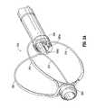
- FIG. 3is a perspective view similar to FIG. 1 illustrating the retractor system in the expanded position.
- FIG. 3Ais an alternate embodiment of the retractor system shown in the expanded position
- FIG. 4is a side view of the retractor system of FIG. 3 .
- FIG. 5illustrates the system of FIG. 1 being used to remove a lesion in a colon, the colon shown in a cutaway view to show the system in perspective, wherein the retractor system is in the expanded position, the tool channels extend from the catheter and the endoscopic tools extend from the tool channels.
- FIG. 6is a side view of the system of FIG. 5 .
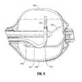
- FIG. 7is a front view of the system of FIG. 5 .
- FIG. 8illustrates the system inserted within the colon.
- FIG. 9illustrates a system of a copending commonly assigned prior application, the system shown to remove a lesion in a colon and having an asymmetric chamber, the colon shown in a cutaway view to show the system in perspective, wherein the retractor system is in the expanded position, the tool channels extend from the catheter and the endoscopic tools extend from the tool channels.
- FIGS. 10A and 10Bare side and front views, respectively, in partial cross section of the system of FIG. 9 .
- FIG. 11is a perspective view of an alternate embodiment of the system showing the catheter and two tool channels.
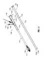
- FIG. 12is a perspective view of the catheter of FIG. 11 being inserted over the proximal end of the endoscope of FIG. 13 (prior to insertion of the endoscope into the colon), the retractor system shown in the collapsed position.
- FIG. 13illustrates insertion of the endoscope through the colon.
- FIG. 14is a perspective view showing the catheter of FIG. 11 being further advanced over the endoscope of FIG. 13 , the retractor system shown in the collapsed position.
- FIG. 15is a perspective view showing the catheter fully advanced over the endoscope to the desired position adjacent the target tissue, the retractor system shown in the collapsed position.
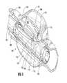
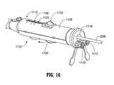
- FIG. 16is a perspective view of the proximal end of the catheter of FIG. 11 .
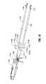
- FIGS. 17A and 17Bare side views in partial cross-section showing movement of the actuator from a proximal position to a distal position to advance the rigidifying structure to stiffen the retractor system.
- FIG. 17Cis a perspective view similar to FIG. 15 showing an alternate embodiment of the rigidifying structure.
- FIG. 17Dis a perspective view similar to FIG. 17C showing the rigidifying structure of FIG. 17C advanced over the flexible element.
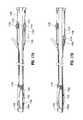
- FIG. 18is a perspective view showing the two tool channels (guides) adjacent the proximal end of the catheter of FIG. 11 for insertion therethrough.
- FIG. 18Ais a perspective view similar to FIG. 18 showing an alternate embodiment of the tool channels.
- FIG. 19Ais a perspective view illustrating the tool channels inserted into the catheter of FIG. 11 and FIG. 19B is a perspective view similar to FIG. 19A illustrating an alternative embodiment of the tool channels.
- FIGS. 20A and 20Bare side cross-sectional views showing movement of the actuator from a proximal position to a distal position to move the retractor system from the collapsed to the expanded position.
- FIG. 21Ais a view similar to FIG. 15 showing the retractor system in the expanded position and further illustrating the tool channels being advanced into the working space (chamber) created by the expansion of the retractor system.
- FIG. 21Bis a view similar to FIG. 21A illustrating an alternate embodiment wherein the tool channels are advanced from the catheter prior to expansion of the retractor system.
- FIG. 22is a view similar to FIG. 21A showing a first endoscopic instrument (tool) advanced from a first tool channel.
- FIG. 23is a view similar to FIG. 22 showing a second endoscopic instrument (tool) advanced from a second tool channel.
- toolan endoscopic instrument
- FIG. 24is a view similar to FIG. 23 showing both endoscopic instruments further advanced from the tool channels.
- FIG. 25is a view similar to FIG. 24 showing the endoscopic instruments further advanced from the tool channels to dissect the lesion on the colon wall.
- FIG. 26is a view similar to FIG. 25 showing the lesion which has been removed from the colon wall by the dissecting instrument placed within the retractor system and
- FIG. 26Ais a view similar to FIG. 26 showing an alternate embodiment without a rigidifying structure.
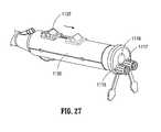
- FIG. 27is a perspective view of the proximal end of the catheter showing proximal movement of the actuator to return the retractor system to the collapsed position for removal from the colon.
- FIG. 28is a view similar to FIG. 26 showing the retractor system in the collapsed position with the lesion therein.
- FIG. 29is a view similar to FIG. 28 showing the covering member closed to encapsulate the lesion for removal.
- FIG. 30is a front view of the system in the expanded position of the retractor system and showing two channels extending from the catheter.
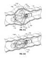
- FIGS. 31A and 31Bare cross-sectional views illustrating the switch for retaining the suture for closing the covering (bag).
- the teachings provided hereinare generally directed to improved methods and devices for operatively treating gastrointestinal disorders endoscopically (in a minimally-invasive manner).
- the systemsinclude an endoscopic surgical suite that is created by the systems disclosed herein.
- the surgical suitehas a reversibly-expandable retractor that expands substantially symmetrically, and the tool channels have a double curved configuration described in detail below which maximize the distance from the tool to the target tissue to thereby maximize space for one or more tools and/or an endoscope to each be maneuvered independently to visualize a target tissue and treat the target tissue from outside the patient in a minimally invasive manner.
- Embodiments taught hereincan provide, among other improvements, an increase in distance between tool ports and the target tissue to enhance the independent maneuverability and triangulation of each of the tools with respect to the target tissue. This increase in distance can also provide a way of obtaining a larger field of view.
- the systems taught hereincan (i) enable a working space to be configured around the target tissue in tortuous body lumens and orifices such as the gastrointestinal tract using controls from outside the body; (ii) provide a flexible, passageway for multiple surgical tools and instruments, such as endoscope and graspers, to be passed from outside the body towards the target tissues; and (iii) organize and control the instruments such as the grasper in the working space from outside the body.
- the catheteris placed over an articulating endoscope by inserting the articulating endoscope through a channel of the catheter; in other embodiments the catheter is placed over a flexible endoscope by backloading the catheter over a flexible endoscope, such as a conventional colonoscope. Then the endoscope, e.g., colonoscope, is inserted to a position adjacent the target tissue and then the catheter is advanced further over the flexible endoscope so the retractor is next to the target tissue.
- a flexible endoscopesuch as a conventional colonoscope
- the endoscopic working instruments (tools) for treating the target tissueare inserted directly through a respective lumen or channel of the multi-lumen catheter.
- the working instrumentscan have a double curve at a distal end which can automatically assume the double curved position when exposed from the catheter so it curves away and then toward the target tissue, or alternatively, the working instruments can have a mechanism actively controlled by the user to articulate/angle the distal tip to obtain the first and/or second curve. In either case, the working instruments would have the double curved configuration to maximize space as described below.
- a flexible tube(instrument guide) is inserted through the lumen or channel of the catheter and acts as a guide for the instrument. That is, the flexible tube is first inserted into the lumen or channel of the catheter and then the endoscopic instrument is inserted through the respective flexible tube.
- the flexible tubehas a double curve at a distal end which can automatically assume the double curved position when exposed from the catheter so it can curve away then toward the target tissue, or alternatively, the flexible tube can have a mechanism actively controlled by the user to articulate/angle the distal tip to obtain the first and/or second curve.
- the curving and maneuverability of the flexible tubescontrols the positioning and orientation of the endoscopic instruments, and therefore the endoscopic instruments need not be provided with a pre-curved tip or articulating mechanisms.
- the double curve wherein the distal end of the tubes curves downwardly away (as viewed in the orientation of FIG. 5 ) from the longitudinal axis of the tube and then upwardly toward and in some embodiments past the longitudinal axisincreases the distance from the opening in the tube to the target lesion as compared to a flexible tube with a single curve curving from the longitudinal axis toward the target lesion. This enhances access and maneuverability of the working tools inserted through the tubes. The same advantages are obtained with working tools with a double curve as compared to a tool with a single curve.
- Minimally-invasive surgeryis desirable to reduce trauma to the patient, speed the healing process, reduce risk and, thus, reduce the length and expense of a hospital stay by minimizing or avoiding tissue damage, or risk of tissue damage.
- Tissue triangulationwherein the tissue is triangulated between two endoscopic instruments, enhances access and maneuverability.
- FIGS. 1-7illustrate one embodiment of a system for operatively treating gastrointestinal disorders endoscopically in and in a minimally-invasive manner.
- the systemhas a flexible outer tube 105 configured for guiding one or more channels 110 and an endoscope 115 within the system 100 .
- the flexible outer tube 105has a lumen, a proximal end (not shown), and a distal end 108 to house, for example, the channel(s) and the endoscope during use of the system 100 .
- the lumencan extend from the proximal to the distal end so the tool channels 110 can be manipulated at a proximal end by the user.
- the outer tube 105can alternatively be a multi-luminal tube, so a separate lumen accommodates the endoscope and the individual tool channels, and during the use of the system 100 , the channel 110 can serve as a guide through which a tool 120 , 125 can be inserted and manipulated in a treatment of a target tissue 190 in the gastrointestinal tract (or other areas) of the subject.
- the channel 110can, for example, be in operable contact with an independently manipulable-and-articulable tool, and the channel can have an elevator component for moving a bendable section.
- the length of the channelin some embodiments is sufficient so it can extend out the proximal end of the outer tube 105 for manipulation by the user.
- the tool channels 110are bendable or articulable at a distal end so they angle away from the longitudinal axis and then toward the target tissue 190 .
- Such bendabilitycan be achieved by providing tool channels (guides) 110 of shape memory material with a shape memorized bent position as shown in FIG. 5 .
- the tool channels 110When contained within the lumen of the outer tube 105 for insertion, the tool channels 110 would have a substantially straightened position, and when advanced from the distal end of the outer tube 105 , would return to the double bent position of FIG. 5 having a first curve 112 and second curve 114 .
- the first curveextends downwardly away from the longitudinal axis and the second curve extends upwardly towards the longitudinal axis.
- the designation “downwardly” and “upwardly”changes.
- the objectiveis to have the distal opening in the tool channels (and/or endoscopic instruments) face toward the target tissue, e.g., target lesion.
- the tool channel 110can have a mechanism such as an elevator component or a control wire attached to a distal end which can be pulled by the user or pulled by an actuator to move the tool channel to the double bent position.
- the tool inserted through the tool channelcan be any tool known to one of skill.
- the tool 120 , 125can include a grasper, a forceps, a snare, a scissor, a knife, a dissector, a clamp, an endoscopic stapler, a tissue loop, a clip applier, a suture-delivering instrument, or an energy-based tissue coagulator or cutter.
- the bendability of the channel 110 for moving a bendable sectionoften a distal end of the channel 110 , manipulates, i.e., bends, the tool 120 , 125 positioned therein.
- At least one channel 110 and/or the endoscope 115can have at least substantial freedom to move within the outer tube 105 during operation, or “float,” such that the system 100 can be considered to be a floating, multi-lumen-catheter retractor system.
- the terms “tool” and “instrument”can be used interchangeably in some embodiments taught herein.
- the tool 120 , 125can be flexible, at least at a distal end such that when the tool channel 110 bends in a manner described herein, it also bends the tool which is positioned therein.
- the tool 120 , 125can be articulable or controllably bendable or composed of shape memory or other material so it bends without reliance on the bendability of the tool channels 110 .
- the endoscopecan have a working channel for insertion of a working instrument such as a grasper or dissector.
- the toolscan be provided with bendability characteristics so that they can be inserted directly through the lumen of the outer tube 105 without the need for tool channels.
- the toolsthemselves have the bendable or articulable feature so as not to rely on the tool channels for achieving the double curve and bending/angling toward the target tissue.
- the systemincludes a reversibly-expandable retractor 150 , as shown in FIG. 1 , that expands to form a treatment space or working chamber 160 in the subject.
- the retractor 150can be configured, for example, for the expansion to occur distal to the distal end 108 of the outer tube 105 .
- the retractor 150can include retractor elements 151 , 152 , 153 , 154 , along with a proximal coupler 198 operably connected to the retractor elements 151 , 152 , 153 , 154 , whether at least substantially attached and/or at least slidably-engaged to the retractor elements 151 , 152 , 153 , 154 , and a distal nexus or hub (or coupler) 199 for a distal point of an operable connection with the retractor elements 151 , 152 , 153 , 154 .
- the outer tubecan have any dimensions believed to be useful to one of skill for the purposes taught herein. Examples of such dimensions are provided in U.S. patent application Ser. No. 13/913,466, incorporated herein in its entirety by reference as noted above.
- the outer tubecan be manufactured from any materials know to be useful to one of skill for the purposes taught herein.
- the outer tubecan comprise a polymer, or perhaps a polymer having embedded wire reinforcement.
- the wire reinforcementcan be a mesh, a braid, a helical coil or any combination thereof.
- the wire reinforcementcan include any material believed by one of skill to be useful for the purposes set-forth herein. Such reinforcements are also described in U.S. patent application Ser. No. 13/913,466.
- the outer tubeshould be flexible, elastically bendable, but sufficiently stiff torsionally to transmit torque from the handle or proximal end of the system to the retractor or distal end of the system.
- the working spaceis formed to create a sufficient working distance for the tools for treatment, e.g., polyp dissection, to enhance maneuvering and manipulating the individual tools, enabling tissue triangulation.
- Working space distanceis also advantageously formed to enhance visibility of the target tissue.
- the double bend described hereinfurther enhances the working space.
- the systemscan include a multi-lumen catheter having at least 2 working channels for manipulating tools and an endoscope, each of the two working channels having 6 degrees of freedom that are independent from each other and the endoscope.
- the ability to independently manipulate the endoscope and toolsallows, for example, one instrument to retract the tissue or lesion away or substantially perpendicular to another instrument, for example, the dissecting instrument, while independently optimizing the endoscope's position and, hence, the view of the treatment area. This would facilitate the removal of tissue with clear margins.
- the channelscan manipulate the tools with several degrees of freedom, 6 degrees of freedom in some embodiments, providing a greatly enhanced maneuverability in the working area when compared to current state-of-the-art systems.
- the at least one independently manipulable-and-articulable toolcan be independently movable to various angles up to about 360 degrees.
- FIGS. 1-8illustrate how a system as taught herein can be positioned for treating a lesion in the ascending colon C, according to some embodiments.
- the description herein regarding removal of a polyp from the wall of the colonis shown and described by way of example as the system (as well as the other systems disclosed herein) can be used for other surgical applications and in other body spaces.
- the systemcan be inserted into the colon C in the non-expanded position of FIG. 1 to treat lesion 190 ( FIG. 5 ).
- a lesioncan be identified by endoscope 115 .
- a sheath or covercan be positioned over the retractor elements 151 , 152 , 153 , 154 to facilitate insertion, with the distal end of the sheath abutting the distal coupler 199 or alternatively overlying the distal coupler.
- the sheathis removed to expose the retractor elements for subsequent expansion to the position of FIG. 3 .
- the retractor elementscan be biased to an expanded position and retained in a collapsed delivery position by the sheath. In such embodiments, removal of the sheath to expose the retractor elements would enable the retractor elements to automatically expand to their expanded position of FIG. 3 .
- Expansion of the retractor elements 151 , 152 , 153 , 154creates a substantially symmetric working space 160 adjacent the lesion 190 .
- the retractor 150in some embodiments can be expanded by moving distal coupler 199 and proximal coupler 198 relative to one another, wherein as the distance between the couplers 199 , 198 , shortens, the retractor elements are forced more laterally with respect to the longitudinal axis of the outer tube (catheter) 105 .
- the retractor elementscan be operably connected to an actuator such that the actuator is moved to bow the retractor elements such as in the embodiment of FIG. 11 discussed in detail below.
- the retractor elementscan be composed of a shape memory such as Nitinol or other material such that when exposed from the outer tube or from a sheath covering the outer tube, they automatically return to their expanded configuration, e.g., their shape memorized expanded configuration.
- shape memorized retractor elementsonce exposed they would automatically move from the position of FIG. 1 to the position of FIG. 3 .
- the system 100has (i) at least one independently manipulable scope 115 , which can be articulable, to be used in viewing the lesion 190 , (ii) at least one tool channel 110 for at least one independently manipulable-and-articulable tool 120 , 125 to be used in the treating of the lesion 190 , and (iii) the retractor 150 .
- the retractor 150can be located distal to the distal end 108 of the outer tube 105 .
- the treating of the lesion 190can include, for example, (i) viewing the lesion 190 with the articulating scope 115 and (ii) using the at least one tool 120 , 125 in the treatment of the lesion 190 with a multidirectional and multi-angular approach to the lesion 190 .
- the independently manipulable-and-articulable scope 115 and the at least one tool 120 , 125can be independently movable axially in the working area 160 , independently rotatable in the working area 160 , and independently bendable in at least one direction in the working area 160 .
- the retractorprovides a larger working area 160 for the treating of the lesion 190 without overstretching, damaging or rupturing the colon.
- the endoscope 115can be articulated in the working space 160 toward the target lesion 190 to improve visibility.
- FIG. 5illustrates a multidirectional and multi-angular approach to the lesion 190 , showing the step of positioning the work area 160 , endoscope 115 , and tools 120 , 125 in relation to the lesion 190 .
- the retractor 150is expanded as shown in FIG. 5 , the user of the system 100 can view and approach the lesion 190 with the tools 120 , 125 from nearly any desired angle within the working space 160 .
- the tool channels 110 as described abovehave a first bend or curve 112 extending away from lesion 190 to increase the distance from the lesion and a second bend or curve 114 extending toward the lesion 190 so endoscopic tools inserted through the tool channels 110 can be directed toward the lesion 190 .
- the distance from the tool channel opening to the lesioncan be maximized and in some embodiments (by reducing the length of the tool channel distal of the second curve such as in FIG. 18A discussed below) be substantially equivalent to the distance from the tool channel opening to the lesion in the asymmetric chamber of FIGS. 9, 10A and 10B which illustrate the asymmetric chamber of copending commonly assigned application Ser. No. 13/913,466.
- the tool channels 110 as shownare advanced through the respective lumens in the multi-lumen catheter or tube 105 and the endoscopic tools or instruments are inserted through the tool channels 110 , with the distal ends of the tools extending distally of the respective tool channel 110 .
- the advantages of the tool channelsare described below in more detail in conjunction with the embodiment of FIG. 11 , and such advantages are applicable to this and other embodiments utilizing the tool channels.
- the endoscopic toolscan be inserted directly into the lumens of the catheter or tube, without the use of tool channels, provided they have the double bending/articulating characteristics described above which enable their manipulation without the use of bendable/articulatable tool channels.
- the different angling of the tools 120 , 125advantageously achieves tissue triangulation to facilitate access, maneuverability and removal of the lesion.
- the dissection tool for excising the lesion 190 from the gastrointestinal tractcan in some embodiments be in the form of an electrosurgical instrument, although other dissecting/excising tools can also be utilized.
- the excised lesion 190can be released into the retractor assembly in preparation for completion of the procedure.
- the tool for excision of the lesion 190can been replaced by another tool for closure of the lesion.
- the defectcan be closed by various methods such as mechanical (e.g., clips staples or structures), glue, electrosurgical energy, etc.
- the retractorcan be collapsed to contain the lesion 190 within the collapsed retractor elements 151 , 152 , 153 , 154 in preparation for removal of the system from the subject, including the use of an optional retractor cover which can be slid over the catheter to further encapsulate the lesion retained within the collapsed retractor elements.
- the distal nexus or hub 199is shown in the shape of a ring, although it can be virtually any shape desirable to one of skill, such as a cone, hemisphere, sphere, and the like, and it may or may not include a port for passage of the endoscope beyond the distal end of the system.
- the proximal coupler 198can be moved toward the distal coupler 199 , the distal coupler moved toward the proximal coupler 198 , or both couplers moved toward each other to reduce their distance to force the retractor elements radially outwardly.
- the extent of outward expansion of the retractor elementscan be controlled by controlling the distance between the proximal and distal couplers 198 , 199 .
- the retractor 150can be repeatedly moved between expanded and retracted positions as desired by adjusting the distance between the coupler 198 , 199 .
- Such controlled expansion of the retractor elementscan also be achieved by operatively coupling the proximal end of the retractor elements to an actuator as in the embodiment of FIG. 11 .
- the retractor elementscan be composed of a material, e.g., shape memory material, to automatically expand when exposed from a catheter or sheath.
- the retractorcan be reversibly stabilized by stiffening an otherwise flexible arrangement of the retractor 150 such as in the embodiment of FIG. 3 .
- the stabilization of the retractor 150can, in some embodiments, include a stabilizer having, for example, an at least substantially-rigid beam 175 to support the expanded retractor 150 .
- the substantially rigid beam 175can be substantially rectangular in cross-section, substantially circular in cross-section or of other cross-sectional shapes. It can be provided of the same or of a stiffer material than the retractor elements. It helps to create a more stabilized chamber as described herein.
- the beam 175can be formed by the more rigid element exposed when the retractor elements are exposed from the outer tube for expansion, or alternatively, can be advanced independently from the outer tube or formed by advancement of a rigidifying structure. More than one of the retractor elements can have a rigidifying structure such that one or more of the retractor elements 151 , 152 , 153 and 154 can be stabilized.
- the rigid beamcan be formed from a flexible beam, in some embodiments, by slidably inserting a rigid rod over a flexible tube that composes the flexible beam. More specifically, in this embodiment, the flexible beam slidably receives thereover a stabilizing or rigidifying structure such as a rigid rod.
- the rigidifying (stabilizing) structurecan be independently actuated by the user by actuating a control, such as a slidable lever, operably connected to the rigidifying structure, such that movement of the actuator distally advances the rigidifying structure over the flexible beam to thereby stiffen the beam.
- the flexible beamcan have a lumen to slidably receive therein a rigidifying structure such as a rigid rod.
- the structure in either versioncan optionally be retracted from the flexible beam to return the system back to the original more flexible state to aid collapsing of the retractor system.
- the beamcan be substantially circular in cross-section, although other cross-sectional shapes are also contemplated.
- the rigid beamlimits deflection of the distal end of the catheter which could otherwise occur by pressure exerted on the distal end by the body lumen wall.
- the at least substantially rigid beamprevents or inhibits deformation of the retractor during creation of forces on the retractor in the expansion and prevents or inhibits bending of the catheter tip.
- the forcesinclude forces from expanding tissue outwards as well as the initial forces applied on the retractor elements to create the working space.
- the rigid rodcan be a straight component comprising a rigid material, for example stainless steel or another metal or alloy, that is slidable in and out of the inner diameter (lumen) of the flexible tube (or alternatively over the outer diameter of the flexible tube).
- the rigid rodcan be pushed forward (i.e., orally) into (or alternatively over) the flexible tube to stiffen and straighten the flexible tube as in the embodiments described above.
- the flexible tube, or flexible beammay also comprise a series of rigid tubes having a flexible, non-stretchable cable passing through the lumens of the tubes.
- the series of rigid tubescan be separated using, for example, a compressible component such as a spring between each of the series of rigid tubes to provide a flexible non-overlapping configuration.
- the compressible componentscompress, and the rigid tubes overlap, converting the flexible beam into a rigid beam.
- Such alternative mechanismscan be utilized with any of the embodiments described herein.
- the retractorcan be unexpanded and flexible.
- the flexible beam of the retractorcan be straightened and stiffened as described herein. Since the system can be flexible and torsionally stiff, the proximal shaft or the handle can be easily rotated as desired relative to the location of the target lesion.
- the flexible beamcan include a polymer.
- the flexible beamcan be, for example, a flexible tube that is reinforced with metal wires, braids, or coils that include, for example, a metal such as a stainless steel or NITINOL.
- the flexible tubecan be kink resistant and transmit torque.
- the flexible tubecan comprise a combination of both flexible sections and rigid sections.
- a flexible sectioncan lie-between rigid sections, for example.
- Such flexible tubescan include composites of overlapping tubes joined using any method known to one of skill, including bonding using epoxy or cyanoacrylates, in some embodiments.
- FIG. 3Aillustrates an alternative embodiment of the retractor system 250 which is identical to the retractor system 150 of FIG. 3 except a rigid beam is not provided. Otherwise the components are identical to the retractor system 150 and are labeled for convenience in the “200” series so the system 250 includes retractor elements 251 , 252 , 253 and 254 , proximal hub 298 , distal hub 299 and tool channel (or instrument) lumens 206 a , 206 b.
- a bridge membercan be utilized to add stability to the retractor.
- the retractor system 150can include a bridge member 144 configured to maintain a desired orientation of the retractor elements during the expansion, the bridge member 144 operably stabilizing at least two 151 , 152 of the four retractor elements 151 , 152 , 153 , 154 . That is, in the embodiment of FIG. 3 , the bridge member 144 is attached to the two retractor elements 151 , 152 .
- the bridge member 144creates a transverse structure for the elements 151 , 152 , limiting side-to side movement.
- Bridge member 144can also include a second bridge section connected to bridge 144 and to retractor elements 153 and 154 thereby connecting all four retractor elements 151 , 152 , 153 , 154 .
- the bridge member 144can be a separate component or alternately integrally formed with one or both of the retractor elements 151 , 152 .
- the bridge membercan be composed of a material similar to the elements 151 , 152 or can be composed of a different material.
- Additional bridge memberscan be provided on the retractor elements to increase stability. Note that one or more bridge members can be used with the other retractor embodiments disclosed herein.
- the bridge member 144can be configured to reduce drag from surrounding tissue during use.
- the bridge member 144can be configured to facilitate a movement of the system in a gastrointestinal tract by designing the bridge member 144 to include a forward component 144 a that is inclined to facilitate forward movement orally, and a reverse component 144 b that is inclined to facilitate reverse movement anally.
- the bridgecan be designed to flex to prevent the retractor elements from collapsing towards each other or bending away from each other, while also providing some spring or elasticity to the system to comply gently with the tissue.
- the bridgecan comprise any suitable material that provides the material characteristics desired.
- the bridgecan be formed from a curved nitinol wire. The ends of the nitinol wires can be connected to the retractor elements using any manufacturing process deemed including, for example, tubing connectors, adhesives, or solder.
- the systems taught hereincan have an outer tube that is wire-reinforced, such as mesh, braided, or the like, to provide kink resistance and torqueability to the system, as well as to further facilitate a positioning of the system in the subject.
- wire-reinforcedsuch as mesh, braided, or the like
- FIG. 3shows multiple lumens 106 a , 106 b .
- Central lumen 106 ccan contain an endoscope such as endoscope 115 described above.
- Lumen 106 bcan contain a first working channel for a first endoscopic tool, and lumen 106 a can contain a second working channel for a second endoscopic tool.
- the working channelscan receive the first and second tools directly therein, or alternatively, receive tool channels (tool guides) described herein for angling the endoscopic tools slidably positioned therein.
- a channelcan be a separate component placed inside the outer tube, or it can be a space remaining in the lumen of the outer tube between separate components that were placed in the outer tube, the separate components including, for example, an endoscope, a working channel, an instrument, a guide, and the like.
- the retractor elementscan have a covering, which add bulk to the retractor elements 151 , 152 , 153 , 154 by increasing its cross-sectional diameter.
- the covering 151 a , 152 a , 153 a , 154 a( FIG. 3 ) extends over an intermediate portion of the respective retractor elements and can be in the form of a heat shrink tubing. The covering helps control expansion by providing a less flexible region.
- the retractorcan be unexpanded and flexible. This flexibility allows the retractor to bend to conform to the bends in the tortuous body lumen, so that it can be advanced with ease and not cause trauma to the lumen.
- the flexible beam of the retractorif provided, can be straightened and stiffened as described herein. Since the system can be flexible and torsionally stiff, the proximal shaft or the handle can be easily rotated as desired relative to the location of the target lesion.
- the endoscope and toolscan be maneuvered independently, for example, to access the lesion at a greater range of angles and improve the view of the lesion and ability to manipulate and dissect the lesion.
- a graspercan be advanced out of the instrument channel into the working space and flexed towards the polyp, grasp the polyp and retract the tissue to expose the base of the polyp for dissection by a dissection tool through the multi-channel systems taught herein.
- the systemcan be floating in the outer tube to enhance flexibility for positioning the system in a subject.
- floating systemis described in commonly assigned co-pending U.S. application Ser. No. 13/531,477, filed Jun. 22, 2012.
- the working (floating) channel and/or endoscopeare floating such that they are (i) at least substantially attached to the lumen of the outer tube at a first proximal location (not shown) and a first distal location and (ii) at least substantially floating in the lumen of the outer tube between the first proximal location (not shown) and the first distal location.
- the separate floating componentsincrease the flexibility and facilitate positioning the system in the subject for the treatment of the target tissue.
- Each tool channelcan be operatively connected to a handle in a manner as described below with respect to the embodiment of FIG. 11 .
- an actuatoris provided to control the angle of the tip by controlling the degree of proximal retraction of the pull wire, with further retraction further bending the tip and less retraction bending the tip to a lesser degree.
- More than one tool channelcan be provided, and the multiple tool channels can be controlled by a single actuator, or alternatively, a separate actuator can be provided for each tool channel.
- various mechanismscan be utilized to lock the actuator(s) in position to maintain the bent position of the tip of the tool channels.
- one or more of the tool channelscan have the pre double bent (double curve) tip which is substantially straight when in the insertion position within the confines of the multi-lumen tube (catheter) and returns to the double bent position when exposed from the confines of the catheter.
- the channels or guidescan be configured to control the trajectory and position of instruments such as forceps in the working space created by the retractor.
- a channelcan be removed from, or inserted through, the outer tube of the system.
- the channelscan be virtually any size considered by one of skill to be useful in the systems described herein.
- a channelcan have an inner diameter ranging from about 1 mm to about 5 mm, from about 2 mm to about 4 mm, from about 1 mm to about 3 mm, or any range therein.
- the length of the channelshould, of course, complement the length of the system.
- the channelcan have a length ranging from about 40′′ to about 72′′, from about 48′′ to about 60′′, from about 42′′ to about 70′′, from about 44′′ to about 68′′, or any range therein in increments of 1′′.
- the channelscan also comprise any material or configuration known to one of skill to be suitable for the uses described herein.
- the channelscan comprise a single polymer layer, multiple polymer layers, a wire reinforced layer, or a combination thereof.
- a side lumenwith a pull wire embedded between the inner layer and the outer layer.
- the side lumencan be located between the inner layer and the reinforcement layer, or the side lumen can be a part of the inner layer.
- the tool (working) channelsflexible tubes or guides positioned inside the outer tube provide a multi-lumen catheter having manipulable passages for independently manipulating tools from outside the body into the working space inside created by expansion of the retractor.
- two inner tubescan be positioned adjacent to the inner surface of the outer tube to provide, effectively, three separate channels.
- the two inner tubescan function as two independent tool channels while the space between these first two channels and the outer tube functions as a third channel.
- the third channelcan be substantially larger than the other two channels.
- the largest diameter channelcan be the channel for the endoscope.
- the inner tubescan be composed of various materials, such as a fluoropolymer such as TEFLON for lubricity to ease tool or endoscope passage and movements.
- a fluoropolymersuch as TEFLON
- Other materials that may be usedinclude, for example, polyethylene, polypropylene, PEBAX, nylon, polyurethane, silicone, and composites thereof, each of which may also be used with a lubricant coating.
- the tubesmay also comprise a metallic wire reinforcement such as a braid, mesh or helical coil, each of which may be embedded in the tube.
- the systems provided hereincan be used in several different methods of treatment.
- the systemscan be used in a method of treating a gastrointestinal lesion using a multidirectional and multi-angular approach to the lesion.
- the methodcan include positioning the system in a subject's gastrointestinal tract, the positioning including placing the retractor in proximity to a target lesion for a treatment; expanding the retractor to create the treatment space for use of the tool; treating the lesion with the tool; collapsing the retractor; and, withdrawing the system from the subject.
- the lesioncan include, for example, a perforation, a tissue pathology a polyp, a tumor, a cancerous tissue, a bleed, a diverticuli, an ulcer, an abnormal vessel, or an appendix.
- a cover or sheaththat covers a portion of the system, including the retractor during delivery of the retractor to a target site, during a treatment of a target tissue at the target site, during a removal of the target tissue, and/or during a removal of the system from the subject, or a combination thereof.
- the retractorhas elements (including the bridge members) that can catch, snag, or otherwise disturb or contact tissue during delivery, or removal, of the retractor to or from the target site.
- the sheathcovers a collapsed configuration of the retractor 150 to render an at least substantially smooth and/or atraumatic surface for a delivery of the retractor 150 to a target site (not shown) for a treatment of a target tissue (not shown).
- the treatment of the target tissuemay include, for example, a dissection of tissue that can be performed within the cover without intermingling the target tissue with the surrounding tissues.
- the dissected tissuemay be a cancerous or other tissue that is desirable to contain during treatment or removal by encapsulating it within the cover.
- the sheathforms a collection means for entrapping and/or pulling out resected tissue.
- cover and “sheath”can be used interchangeably, and one of skill can appreciate that such embodiments are open to improvements, as taught herein.
- the sheathis clear and is attached at one end to the distal hub or coupler and extends proximally past the proximal coupler or hub and is attached to the outer surface of the catheter.
- the sheathcan be attached at a proximal end to proximal coupler.
- the sheathcan be at least substantially closed around the retractor 150 during delivery, and can be designed to open as the retractor 150 is expanded to create the working space 160 for the treatment.
- the expansion of the retractor elements and the sheathcan be independent.
- the sheathcan be perforated longitudinally (not shown), designed such that the sheath opens upon expansion of the retractor through tearing of the perforation at the target site.
- a tongue-and-groove mechanismfor example a ZIPLOCK mechanism, can be used to at least substantially close a slit at the top of the retractor which can also open upon the expansion of the retractor at the target site.
- a larger perforation, or unclosed portioncan remain in the sheath to facilitate the tearing or opening of the sheath at the target site upon the expansion of the retractor 150 .
- the terms “slit” and “opening”can be used interchangeably.
- the sheathcan be reversibly opened, such that the sheath can be re-closable.
- a drawstring, cable, or wirecan be operably positioned in communication with the opening for the re-closing of the opening by pulling or pushing the drawstring, cable, or wire from outside the patient during the treatment.
- the edges of the openingcan form longitudinal pockets or channels for pulling or pushing the drawstring, cable, or wire as desired from outside the patient during the treatment, such as by routing the drawstring, cable, or wire through the system and, perhaps, through the handle as with the other actuation means.
- a drawstringis used to re-close the sheath, wherein the strings can be tensioned at the handle to close the slit, or loosened to allow the retractor to expand.
- the sheathhas a stiffening strip running transversely around the mid portion of the cage to facilitate the cage wires expanding without catching on the surrounding sheath.
- the stiffening stripcan be another layer of the sheath welded or glued onto the existing sheath. It can also be formed as a thickened area. Alternatively, a stiffer material can be inserted in the pocket running transversely. The stiffening material may be the same as that of the sheath.
- the expandable retractor elementsare expanded away from the sheath.
- the sheathcan remain open at a surface facing the target tissue to be treated, e.g., removed, from the patient's body.
- the sheathcan remain closed and be opened by an endoscopic tool to receive the removed lesion.
- FIGS. 11-30illustrate alternative embodiments of the system, designated generally by reference numeral 1100 .
- System 1100includes a multi-lumen catheter or tubular member 1110 configured to receive one or more tool channels or instrument guides (also referred to herein as flexible tubes).
- FIG. 11shows two tool channels 1122 and 1124 , it being understood that in some embodiments, only one tool channel can be utilized and in other embodiments more than two tool channels can be utilized, with the catheter provided with a sufficient number of lumens.
- the tool channels 1122 , 1124can be packaged as a kit with the catheter 1110 as shown in FIG. 11 . Alternatively, the tool channels 1122 , 1124 can be packaged separately. In other embodiments, the tool channels are packaged already inside the lumens of the catheter 1110 .
- Each tool channel 1122 , 1124has a lumen (channel) to receive an endoscopic instrument (tool) therethrough.
- Tool channel 1122has a double curve (bend) at its distal tip 1122 a defining a first curve (bend) 1122 b extending away (downwardly as viewed in the orientation of FIGS. 11 and 18 ) from the longitudinal axis and then transitioning into a second curve 1122 c extending in a second opposite direction (upwardly as viewed in the orientation of FIGS. 11 and 18 ) toward the longitudinal axis.
- Tool channel 1124similarly has a double curve (bend) at its distal tip 1124 a defining a first curve (bend) 1124 b extending away (downwardly as viewed in the orientation of FIGS.
- the first curveincreases the distance from the distal opening 1122 d , 1124 d of the tool channel to the target lesion as compared to a single curve which does not have a downward bend.
- the tool channels (flexible tubes or guides) 1122 and 1124are inserted through the proximal end of the catheter 1110 and advanced through respective lumens 1112 , 1114 in the catheter 1110 (see FIG. 12 ). As shown in FIG.
- the catheter 1110can include ports 1115 , 1117 , cooperating with the lumens 1112 , 1114 , respectively ( FIG. 12 ), which can include valves to maintain insufflation when the tool channels 1122 , 1124 are inserted therethrough and translated axially therein.
- the pre-bent tips 1122 a , 1124 aare preferably substantially straightened to facilitate advancement through the lumens.
- the tool channels 1122 , 1124are advanced sufficiently distally so the distal tips 1122 a , 1124 a are exposed from the confines of the walls of the catheter lumens 1112 , 1114 , the tips 1122 a , 1124 a , return to the pre-set double curved position.
- FIG. 18illustrates in phantom the straightened position of the tool channels 1122 , 1124 for movement within the catheter 1110 .
- the tool channels 1122 , 1124can be composed of superelastic material, although other materials to provide the curved tip which returns from a substantially straight insertion shape to a curved shape when exposed can also be used, such as stainless steel. Also, as in the other embodiments disclosed herein, shape memory properties of material such as Nitinol can be used with a memorized curved tip shape. In alternative embodiments as described above, the tool channels 1122 , 1124 can have a mechanism such as a pull wire which is actuated to bend its distal end. The tool channels 1122 , 1124 in the embodiments of FIGS.
- the tool channelscan be attached to the catheter, e.g., attached at proximal and distal ends to provide floating channels.
- the tool channels 1122 , 1124can optionally include markings 1123 , 1125 , respectively, at a region proximal to the catheter 1110 to provide a visual indicator to the user of the depth of insertion of the tool channels 1122 , 1124 through the catheter lumens 1112 , 1114 .
- the tool channels 1122 , 1124can have a luer fitting 1127 , 1129 , respectively, ( FIGS. 11 and 19A ) with a valve, at the proximal end which can close off backflow of insufflation gas from the body. This maintains insufflation when the endoscopic tool is inserted through the tool channels 1122 , 1124 as described below.
- the tool channelsin an alternate embodiment shown in FIG.
- valves 1121 A, 1121 Bare proximal of luer fittings 1127 ′, 1129 ′.
- the tool channels 1124 ′, 1126 ′are identical to tool channels 1124 , 1126 in all other respects.
- the distal tip of the tool channels 1122 , 1124extend radially beyond the longitudinal axis of the tool channel 1124 , 1126 so the distal opening is beyond the axis.
- the distal tip 1222 a , 1224 adoes not extend radially beyond the longitudinal axis so the distal opening is substantially aligned with the longitudinal axis of the tool channels 1124 , 1126 .
- This reduced length after (distal) the second curveincreases the distance from the distal open to the lesion and in some embodiments can be substantially equivalent to the distance obtained with the asymmetric chamber discussed above.
- the tool channels of FIG. 18Aare otherwise identical to the tool channels of FIG. 18 .
- the distal opening of the tool channelscould be below (as viewed in the orientation of FIG. 18A ) the longitudinal axis of the tool channels to further increase the distance from the distal opening to the target lesion.
- the tool channels 1122 , 1124can be composed of a flexible soft material, such as Pebax.
- a superelastic nitinol backbonecan in some embodiments be embedded in the wall of the Pebax material, e.g., within the curved portion. Other materials are also contemplated.
- Catheter 1110also preferably has a lumen 1116 (see e.g., FIG. 16 ) configured and dimensioned to receive an endoscope 1200 .
- the lumen 1116is dimensioned to receive a conventional endoscope, e.g., a conventional colonoscope, and the catheter 1110 is backloaded over the endoscope. This is described in more detail below in conjunction with the method of use.
- the lumen 1116can receive an articulating endoscope.
- the endoscopecan be inserted into the catheter and inserted into the body lumen.
- catheter 1110includes a handle housing 1130 at the proximal portion 1113 which contains two actuators: actuator 1132 for controlling movement of the retractor system 1150 and actuator 1134 for controlling movement of the rigidifying (stabilizing) structure, if provided.
- Catheter 1110also includes tubing 1139 having a luer coupling 1137 and a control switch 1175 (see FIGS. 31A, 31B ) for closing off an internal gasket 1176 .
- the suture 1172 for closing covering 1170is secured by the elastomeric gasket 1176 as the switch 1174 is moved from the position of FIG. 31A to the position of FIG. 31B . More particularly, in the initial position of FIG.
- the ball valve 1174seated in a slot in the housing 1179 , does not apply a force to the gasket 1176 .
- Thisenables the suture 1172 to freely move within the lumen of the catheter.
- the switch 1175is slid forward, thereby camming the ball 1174 downwardly (as viewed in the orientation of FIG. 31B ) to collapse the lumen in the gasket 1176 against the suture 1172 to thereby secure the suture 1172 .
- Catheter 1110also has tubing 1136 having a one-way stopcock 1038 to provide an insufflation port. This port can be used to supplement the insufflation gas provided by the endoscope 1200 .
- the insufflation gasflows through lumen 1116 in the area around the endoscope 1200 since the cross sectional dimension of the lumen 1116 exceeds the cross-sectional dimension of the endoscope 1200 to leave a sufficient gap.
- the tubings 1139 , 1136are positioned distal of the actuators 1132 , 1134 ,
- the retractor system 1150which forms a body lumen reshaping or reconfiguring system, and with initial reference to FIG. 12 , the retractor system 1150 is positioned at the distal portion 1111 of the catheter 1110 (distal of proximal hub 1140 ) and includes flexible retractor elements 1152 , 1154 1156 and 1158 .
- Retractor elements 1152 , 1154 , 1156 , 1158form the expandable elements which create the working chamber (space) within the body lumen and form a substantially symmetric cage to improve visibility and working space.
- the double curved tool channels(or alternatively double curved instruments) accommodate for this shaped chamber so as not to sacrifice distances from the target lesion which would otherwise occur if the tips had a single curve.
- retractor elements 1152 , 1154 , 1156 , 1158move from a collapsed insertion position wherein they preferably do not extend beyond the transverse dimension of the catheter 1110 to an expanded position wherein they bow laterally outwardly and have a transverse dimension extending beyond the transverse dimension of the catheter 1110 .
- the retractor elements 1152 , 1154 , 1156 , and 1158expand to both sides of a plane passing through the longitudinal axis of the catheter 1110 , thereby creating the substantially symmetric cage or working space 1151 .
- Retractor elements 1152 , 1154have a bridge member 1155 to add stability to the retractor and maintain a desired orientation of the retractor elements during the expansion.
- the bridge member 1155is attached to the two retractor elements 1152 , 1154 , preferably at an intermediate portion, to create a transverse structure for the elements 1152 , 1154 , limiting side-to side movement.
- bridge member 1155has a first arm 1155 a connected to retractor element 1152 and a second arm 1155 b attached to retractor element 1154 .
- the upper surface(as viewed in the orientation of FIG. 15 ) can be arcuate as shown.
- the bridge member 1155can be a separate component attached to the retractor elements by tubular elements 1159 a , 1159 b , which are attached to retractor elements 1152 , 1154 , respectively.
- the tubular element 1159 a , 1159 bhas a first opening to receive the retractor element and a second opening to receive an arm of the bridge member.
- the tubular elements 1159 a , 1159 balso bulk up the diameter of the retractor elements 1152 , 1154 since in some embodiments the retractor elements 1152 , 1154 are about 0.035 inches in diameter (although other dimensions are contemplated). Other methods of attachment of the bridge members are also contemplated.
- the bridge member 1155can be integrally formed with one both of the retractor elements 1152 , 1154 .
- the bridge member 1155can be composed of a material similar to the elements 1152 , 1154 or can be composed of a different material.
- the bridge member 1155can also include legs 1155 d and 1155 e which are connected to lower retractor elements 1158 , 1156 , respectively, to attach the bridge member to lower elements 1158 , 1156 , respectively, to add to the stability of the retractor system.
- These leg membersare preferably composed of soft elastomeric material such as polyurethane tubing to add more structure to the cage and facilitate expansion of the cage in a more predictable fashion.
- Additional bridge memberscan be provided on the retractor elements 1152 , 1154 to increase stability.
- the bridge member 1155can, in some embodiments, in the collapsed position, extend substantially axially as in FIGS. 15 and 17A , but change to angle inwardly (downwardly) toward the longitudinal axis of the catheter 1110 in the expanded position of the retractor elements 1152 , 1154 such as in FIG. 21A .
- An additional bridge member 1157extends between the two lower (as viewed in orientation of FIG. 15 ) retractor elements 1156 , 1158 .
- These elements 1156 , 1158can help open up the lower section of the retractor system 1150 , and help form the cage for the working space, and the bridge member(s) 1157 can help to stabilize these elements 1156 , 1158 , e.g., limit side to side movement.
- the bridge member 1157 as shownhas arms 1157 a , 1157 b connecting to elements 1156 , 1158 , respectively.
- the bridge member 1157can be a separate component attached to the retractor elements by tubular elements 1161 a , 1161 b which are attached to retractor elements 1156 , 1158 , respectively.
- the tubular elements 1161 a , 1161 bcan have a first opening to receive the element 1156 or 1158 and a second opening to receive an arm of the bridge member 1157 .
- Other ways of attaching the bridge member(s)are also contemplated.
- the bridge member 1157can be integrally formed with one or both of the retractor elements 1156 , 1158 .
- the bridge member 1157can be composed of a material similar to the elements 1156 , 1158 or can be composed of a different material.
- Additional bridge memberscan be provided on the retractor elements 1156 , 1158 to increase stability.
- the bridge member 1157can, in some embodiments, in the collapsed position, be substantially parallel with a longitudinal axis of the catheter 1110 or extend substantially axially such as in FIG. 15 and change to an angular position in the expanded position of the retractor elements.
- the catheter 1110includes a proximal coupler (cap) 1140 through which the retractor elements extend.
- Handle housing 1130includes a longitudinally extending slot 1131 ( FIG. 16 ) along which retractor actuator 1132 axially slides.
- the retractor elements 1152 , 1154 , 1156 , and 1158are coupled to the actuator 1132 via block 1146 , shown in FIGS. 20A and 20B . That is, each retractor element 1152 , 1154 , 1156 , 1158 has a proximal extension that extends through the respective lumen in the catheter 1150 and is connected at its proximal end to the block 1146 . In this manner, when the actuator 1132 is moved along axial slot 1131 from its proximal position of FIG.
- the block 1146is moved distally, thereby forcing the retractor elements 1152 , 1154 , 1156 , 1158 laterally outwardly since the elements 1152 , 1154 , 1156 , 1158 are fixedly attached to the distal coupler 1148 at their distal ends.
- the elements 1152 , 1154 , 1156 and 1158can be fixed within slots formed in the distal coupler 1148 .
- the proximal and distal couplers 1140 , 1148can have openings dimensioned to receive an endoscope when the catheter 1110 is backloaded over the endoscope as described below.
- Housing 1130can include a plurality of teeth (not shown) for engagement by a tooth coupled to the actuator 1132 , thereby forming a retaining or locking mechanism to retain the retractor elements in one of several select positions.
- a release mechanism for the retaining or locking mechanismcan be provided.
- retractor elementscan be utilized, including for example providing relatively movable couplers 1140 , 1148 to expand the retractor elements 1152 , 1154 , 1156 , 1158 in the same manner as the couplers described above, e.g., couplers 198 , 199 .
- the retractor elementscan also alternatively be made of self-expanding material, such as shape memory material, which expand when exposed from the catheter or sheath.
- Retractor elements 1152 , 1154 , 1156 , and/or 1158can optionally have a small crimp forming a flattened position at a distal end adjacent where they are anchored to the distal coupler 1148 . This reduces the bending stiffness at the point so it acts like a hinge to create a more predictable direction of expansion, e.g., to deflect upwardly (or downwardly) and slightly outwardly. This also decreases the amount of force required to initiate the bending.
- Such flattened portioncan also be used with the retractor elements of the other embodiments disclosed herein.
- the retractor system 1150can be configured to reversibly stiffen an otherwise flexible arrangement of the retractor 1150 .
- retractor system 1150can include a substantially-rigid beam to support the expanded retractor 1150 which helps to create a more stabilized chamber (or cage) as described herein.
- a flexible tube or beam 1160is provided in the collapsed configuration, whereas in FIG. 17B , the retractor system has a rigid beam that is formed from the flexible beam 1160 .
- the flexible beam 1160is in the form of a rod or tube 1165 having a lumen to slidably receive a stabilizing or rigidifying structure such as a rigid tube or rod (beam) 1162 .
- the rigidifying (stabilizing) structure 1162is independently actuated by the user by movement of actuator 1134 .
- Actuator 1134is slidably mounted within a longitudinally extending slot of housing 1130 .
- rigidifying structure 1162In the initial position of FIG. 17A , rigidifying structure 1162 is retracted within a lumen of the catheter and either not engaged, or only partially engaged, with flexible tube (or rod) 1160 .
- Rigidifying structure 1162is attached at is proximal end to sliding block 1164 which is operably connected to actuator 1134 .
- actuator 1134is slid distally to the position of FIG. 17B , thereby advancing sliding block 1164 and the attached stabilizing structure 1162 distally.
- the rigidifying structure 1162can optionally be removed from the flexible beam 1060 to return the system back to the original more flexible state to aid collapsing of the retractor system 1050 by sliding the actuator 1134 in the reverse direction (proximally) within the axial slot, thereby withdrawing rigidifying structure 1162 from the advanced position within flexible tube 1160 .
- the rigidifying structure 1164is in the form of a structure having a proximal and distal metal tubular structure joined by a flexible braid polyimide tube.
- other structuresare also contemplated.
- structures 1160 , 1162can be substantially circular in cross-section, although other cross-sectional shapes are also contemplated.
- the rigid beamlimits deflection of the distal end 1111 of the catheter 1110 which could otherwise occur by pressure exerted on the distal end by the body lumen wall.
- the actuatorcan include a connector 1135 having a tooth or pawl 1137 to engage a tooth on the rack 1138 positioned within housing 1130 to retain the rigidifying structure 1164 in one of several selected positions.
- the rigidifying structureis advanced over the flexible element. More specifically, flexible beam 1160 ′ is rigidified by movement of a rigidifying structure, e.g., tubular member 1162 ′, over the flexible beam 1160 ′. That is, rigidifying member 1162 ′ has a lumen configured and dimensioned to receive flexible beam 1160 ′ as it is passed thereover in the direction of the arrow of FIG. 17C . Note that flexible element 1152 has been removed from FIGS. 17C and 17D for clarity. Actuator 1134 , as well as alternative methods, can be utilized for such movement
- the retractor systemdoes not include a rigidifying structure.
- the retractor system 1350having retractor elements 1352 , 1354 , 1356 and 1358 , is the same as retractor system 1150 .
- a covering or cover 1170is preferably provided at a distal end of the catheter 1110 .
- Covering 1170 in the illustrated embodimentis mounted around the perimeter of the proximal coupler 1140 and the distal coupler 1148 .
- the cover 1170is pleated and sealed around the couplers (caps) 1140 , 1148 by a heat shrink wrap.
- the cover 1170is positioned around the elements 1152 , 1154 , 1156 , 1158 in the collapsed insertion position, with an opening in the cover 1170 facing toward the target tissue, e.g., the lesion to be removed. That is, in the orientation of FIG. 15 , the opening in cover 1170 faces upwardly.
- the cover 1170can be configured to have an opening in the collapsed position, or, alternatively, it can provided with a slit which can be opened due to stretching when the retractor elements 1152 , 1154 , 1156 , and 1158 are moved to the expanded position.
- the retractor elements 1152 , 1154are expanded, they move past the cover 1170 toward the target tissue.
- the edges of the cover 1170can be attached to the retractor elements 1152 , 1154 , 1156 , and 1158 thereby move with the retractor elements.
- the target tissueis removed by the endoscopic instruments described herein, the removed tissue is placed within the cover 1170 , and the cover 1170 is closed, e.g., by a suture or string 1172 shown in FIG.
- the suture 1172can be embedded in a wall of the cover 1170 or in pockets or channels formed in the cover 1170 , where it is permanently fixed at a distal anchor point, and pulled proximally to tension the suture 1172 and close the cover 1170 .
- the cover 1170by covering the retractor elements 1152 , 1154 , 1156 , 1158 can provide a smooth and atraumatic surface for the delivery of the retractor system to the target site.
- the cover 1170also helps to prevent unwanted tissue, e.g. the luminal walls, from entering through the spaces between the beam 1160 and retractor elements during the surgical procedure.
- the two ends of suture 1172extend out of tubing 1139 ( FIG. 11 ). Their proximal ends can be covered by a length of tubing to facilitate grasping by the user.
- the suture 1172extends through switch 1137 and tubing 1139 , through a dedicated lumen (channel) in the catheter, through the covering 1170 , and is looped at the distal cap (coupler) 1148 where it is attached (anchored). During the procedure, the suture 1172 remains untensioned. After the tissue is placed within the cover (bag) 1170 , the two proximal ends of the looped suture 1172 are pulled proximally to tension the suture 1172 to close the cover 1170 . The switch can then be moved to frictionally engage the suture 1172 to secure it so it locks in the tensioned position to maintain closure of the cover 1170 .
- FIG. 11The use of the system of FIG. 11 will now be described with reference to removing a lesion, such as a polyp, from a colon wall, it being understood, however, that the system 1100 can used for other procedures within the colon or the gastrointestinal tract, as well as used for other procedures in other body lumens or body spaces of a patient.
- a lesionsuch as a polyp
- a distal viewing endoscope 1200in which the system 1100 has been backloaded over the proximal end 1201 , is inserted through lumen A in the colon B in a procedure to remove the target polyp C from the wall of the colon B.
- the endoscope 1200 in this embodimentis a distal viewing scope with a wide distal viewing area of about 150-170 degree range so the polyp C and surrounding area can be visualized.
- the system 1100is further advanced over the endoscope 1200 .
- Distal coupler (cap) 1148has an opening 1148 a
- proximal coupler (cap) 1140has an opening communicating with the lumen 1116 ( FIG. 16 ) of the catheter 1110 to enable such backloading of the endoscope 1200 and advancement of the system 1100 thereover.
- the catheter 1110is advanced over the endoscope 1200 as shown in FIG. 14 until it reaches the target site as shown in FIG. 15 , with the retractor system 1150 aligned with the polyp C.
- the retractor system 1150in this insertion position of the catheter 1110 , the retractor system 1150 is in the non-expanded (or collapsed) position, with retractor elements 1152 , 1154 , 1156 , 1158 preferably not exceeding, or only slightly exceeding, the transverse dimension of the catheter 1110 . In this position, the retractor elements are covered by the covering 1170 . As shown, in this position, the distal end 1202 of the endoscope 1200 is preferably positioned at the end of proximal coupler 1140 and does not extend into the working space 1151 to thereby leave more room for maneuvering of the endoscopic instruments within the working space.
- endoscopecan extend into the working space 1151 .
- actuators 1134 and 1132are in their retracted position as shown in FIG. 16 .
- the actuator 1134is moved distally from the position of FIG. 17A to the position of FIG. 17B (see also the arrow in FIG. 16 ) to advance rigidifying structure 1162 from the retracted position to an advanced position within lumen 1165 of flexible tube 1160 .
- the retractor system 1150can alternatively be stiffened/stabilized by advancement of a rigidifying structure over the flexible element as shown in FIGS. 17C and 17D .
- an actuatoris not provided and this step is skipped.
- the retractor system 1150is now expanded.
- Actuator 1132is advanced distally from the position of FIG. 20A to the position of FIG. 20B (see also FIG. 19 ).
- This advances block 1146(which is operably coupled to retractor elements 1152 , 1154 , 1156 , and 1158 as discussed above) which forces retractor elements 1152 , 1154 , 1156 and 1158 laterally outwardly to the position of FIG. 20B , thereby creating the substantially symmetric working space (chamber).
- tool channels 1122 , 1124are inserted through the ports 1115 , 1117 in the proximal region of the catheter 1110 (see FIG. 19A ) and advanced by the user through the catheter lumens 1112 , 1114 so they extend out the distal openings of the lumens 1112 , 1114 and into the chamber 1151 as shown in FIG. 21A .
- their distal tips 1122 a , 1124 areturn to their double curved (double bent) position, curving downwardly, then upwardly (as viewed in the orientation of FIG. 21A ) toward the polyp C. Note in FIG.
- the retractor elementsare first expanded, followed by insertion of the tool channels 1122 , 1124 out of the catheter lumens 1112 , 1114 and into the working space 1151 .
- the tool channels 1122 , 1124can be inserted through the catheter lumens 1112 , 1114 and into the working space 1151 prior to expansion of the retractor elements 1152 , 1154 .
- This alternate methodis shown in FIG. 21B , with the tool channel tips 1122 a , 1122 b exposed, but the retractor system 1150 still in the non-expanded position.
- the tool channels 1122 , 1124can be independently rotated and/or moved axially to adjust their position with respect to the polyp C.
- the terms upwardly and downwardly as used hereinrefer to the orientation of the system in the referenced Figures. If the position of the system (and target tissue) changes, the orientation and terms would also change.
- endoscopic instrument (tool) 1210is inserted through the luer fitting 1129 ( FIG. 19A ) of the tool channel 1124 and advanced through the lumen (channel) of the tool channel.
- a first endoscopic instrument 1210extends from tool channel 1124 and follows the double curve of the tool channel 1124 .
- a second endoscopic instrument (tool) 1220is inserted through the luer fitting 1127 of tool channel 1122 and advanced through the lumen of the tool channel 1122 .
- the second endoscopic instrumentfollows the double curve of the tool channel 1122 .
- the tool channelscan include a valve, such as the hemostatic valves as shown in FIG.
- the endoscopic instruments 1210 , 1220can be moved further axially as shown in FIGS. 24 and 25 to extend further from the tool channels 1122 , 1124 to contact and treat, e.g., remove, the polyp C.
- This movement of the endoscopic instruments shown by comparing FIGS. 23-25shows the advantage of the tool channels 1122 , 1124 .
- the tool channels 1122 , 1124can be considered as defining a fixed curve, the fixed curve being the second curve 1122 c and 1124 c .
- endoscopic instruments 1210 , 1220are axially advanced, they move closer to the target polyp C, without a change in curvature and without a change in their axial position with respect to the polyp C, thus providing an extra degree of freedom.
- the endoscopic instrument 1210which in the illustrated embodiment is a grasper, applies tension on the polyp C while the electrosurgical dissector 1220 dissects/severs the polyp C from the colon wall B.
- Other endoscopic instruments for polyp removalcan also be utilized.
- a single tool channelcan be utilized and another endoscopic instrument, e.g., a grasper or a dissector, can be inserted through a working channel (lumen) of the endoscope.
- a working channele.g., a grasper or a dissector
- tissue triangulationcan be achieved as depicted by the dotted lines in FIG. 30 .
- the double curve(somewhat U-shaped tip) increases the distance of the distal openings in the tool channels 1122 , 1124 from the target tissue as compared to a tool channel with a single curve. This is especially advantageous when used with a substantially symmetric chamber which cannot form the same space as the asymmetric chamber described in the U.S. application Ser. No. 13/913,466 noted above as the colon or body lumen has a maximum expansion before it is overstretched or damaged.
- reshapingcan occur with an increased distance for the working instruments from the lesion and increased working space.
- the distance for the working instruments from the lesionwould be reduced compared to the asymmetric chamber if not for the double curve provided by the present invention. Maintaining this comparable increased distance can be appreciated by comparing FIGS. 6 and 10A as discussed above, and further by the shorter distal length of FIG. 18A .
- the asymmetric chamber of FIGS. 9 and 10Areconfigures the lumen to increase and optimize the working space around the target tissue (as it creates more space around the tissue) and increases the distance between the target tissue and opposite wall.
- a non-working spaceis expanded at the expense of the working space near the target tissue.
- the distance between the target tissue and longitudinal axis of the catheteris decreased.
- the distance from the target tissue to the tool guides (channels)is increased by the double bent tip, achieving the objective of positioning the distal opening in the tool guides as far away from the target tissue as possible.
- the first bendincreases the distance from the distal opening of the tool guide from the target tissue.
- the second benddirects the distal opening toward the target lesion.
- Actuator 1134can be moved proximally to return the retractor system to the more flexible condition if desired.
- Actuator 1132is moved proximally in the direction of the arrow of FIG. 27 to return the expanded retractor elements 1152 , 1154 , 1156 and 1158 to their collapsed position of FIG. 28 for removal of the catheter 1110 .
- the string or suture 1172is then tensioned to close the cover (bag) 1170 as shown in FIG. 29 , forming a bag to encapsulate the polyp C.
- the switch 1175can then be moved to the position of FIG.
- FIG. 29shows the retractor elements, bridge elements, beam etc. in phantom insider the bag/cover 1170 .
- endoscopic instrumentscan be used for partial tissue resection, for example, submucosal or subserosal resection.
- the endoscopic instrumentscould also be utilized for full thickness tissue resection.
- the instrumentsenable removal of the lesion with healthy tissue margins, thereby providing a complete, en-block removal of the pathological lesion.
- the handlecan be any of a variety of shapes to provide a desired or ergonomic position for operation of the system.
- the retractor actuatorcan be configured as a finger-activated button on the handle that slides back and forth through a slot in the handle to expand or collapse the retractor elements.
- a means for dynamically adjusting or ratcheting the retractor positioncan be provided along the handle slot to lock the position of the retractor elements in place when the retractor actuator button is not pressed.
- a button on the opposite side of the handlecan be operatively connected to the stabilizer subsystem to convert the flexible beam into a rigid beam, or convert the rigid beam into a flexible beam.
- the handlecan have inner channels routed axially, for example, within the body of the handle and in communication with ports for tools and endoscope introduction into the outer tube.
- the handlecan be configured to require that the stabilizer actuator is activated before the retractor actuator can be activated, serving as a “safety” mechanism in the operation of the system
Landscapes
- Health & Medical Sciences (AREA)
- Life Sciences & Earth Sciences (AREA)
- Surgery (AREA)
- Heart & Thoracic Surgery (AREA)
- Engineering & Computer Science (AREA)
- General Health & Medical Sciences (AREA)
- Animal Behavior & Ethology (AREA)
- Veterinary Medicine (AREA)
- Public Health (AREA)
- Biomedical Technology (AREA)
- Molecular Biology (AREA)
- Nuclear Medicine, Radiotherapy & Molecular Imaging (AREA)
- Medical Informatics (AREA)
- Optics & Photonics (AREA)
- Pathology (AREA)
- Physics & Mathematics (AREA)
- Biophysics (AREA)
- Radiology & Medical Imaging (AREA)
- Anesthesiology (AREA)
- Hematology (AREA)
- Mechanical Engineering (AREA)
- Pulmonology (AREA)
- Surgical Instruments (AREA)
Abstract
Description
Claims (20)
Priority Applications (3)
| Application Number | Priority Date | Filing Date | Title |
|---|---|---|---|
| US15/331,858US10588504B2 (en) | 2009-12-16 | 2016-10-22 | Multi-lumen-catheter system for a minimally-invasive treatment |
| US16/779,784US11406256B2 (en) | 2009-12-16 | 2020-02-03 | Multi-lumen-catheter system for a minimally-invasive treatment |
| US17/869,406US20220354360A1 (en) | 2009-12-16 | 2022-07-20 | Multi-lumen-catheter system for a minimally-invasive treatment |
Applications Claiming Priority (7)
| Application Number | Priority Date | Filing Date | Title |
|---|---|---|---|
| US28707709P | 2009-12-16 | 2009-12-16 | |
| US12/970,604US8506479B2 (en) | 2009-12-16 | 2010-12-16 | Substantially rigid and stable endoluminal surgical suite for treating a gastrointestinal lesion |
| US13/531,477US8932211B2 (en) | 2012-06-22 | 2012-06-22 | Floating, multi-lumen-catheter retractor system for a minimally-invasive, operative gastrointestinal treatment |
| US13/726,147US9161746B2 (en) | 2009-12-16 | 2012-12-23 | Substaintially rigid and stable endoluminal surgical suite for treating a gastrointestinal lesion |
| US13/913,466US9186131B2 (en) | 2009-12-16 | 2013-06-09 | Multi-lumen-catheter retractor system for a minimally-invasive, operative gastrointestinal treatment |
| US14/099,943US9565998B2 (en) | 2009-12-16 | 2013-12-07 | Multi-lumen-catheter retractor system for a minimally-invasive, operative gastrointestinal treatment |
| US15/331,858US10588504B2 (en) | 2009-12-16 | 2016-10-22 | Multi-lumen-catheter system for a minimally-invasive treatment |
Related Parent Applications (1)
| Application Number | Title | Priority Date | Filing Date |
|---|---|---|---|
| US14/099,943ContinuationUS9565998B2 (en) | 2009-12-16 | 2013-12-07 | Multi-lumen-catheter retractor system for a minimally-invasive, operative gastrointestinal treatment |
Related Child Applications (1)
| Application Number | Title | Priority Date | Filing Date |
|---|---|---|---|
| US16/779,784ContinuationUS11406256B2 (en) | 2009-12-16 | 2020-02-03 | Multi-lumen-catheter system for a minimally-invasive treatment |
Publications (2)
| Publication Number | Publication Date |
|---|---|
| US20170079636A1 US20170079636A1 (en) | 2017-03-23 |
| US10588504B2true US10588504B2 (en) | 2020-03-17 |
Family
ID=50728582
Family Applications (5)
| Application Number | Title | Priority Date | Filing Date |
|---|---|---|---|
| US14/099,943Expired - Fee RelatedUS9565998B2 (en) | 2009-12-16 | 2013-12-07 | Multi-lumen-catheter retractor system for a minimally-invasive, operative gastrointestinal treatment |
| US15/331,858ActiveUS10588504B2 (en) | 2009-12-16 | 2016-10-22 | Multi-lumen-catheter system for a minimally-invasive treatment |
| US15/418,720AbandonedUS20170135567A1 (en) | 2009-12-16 | 2017-01-28 | Multi-lumen-catheter system for a minimally-invasive treatment |
| US16/779,784Active2031-11-15US11406256B2 (en) | 2009-12-16 | 2020-02-03 | Multi-lumen-catheter system for a minimally-invasive treatment |
| US17/869,406PendingUS20220354360A1 (en) | 2009-12-16 | 2022-07-20 | Multi-lumen-catheter system for a minimally-invasive treatment |
Family Applications Before (1)
| Application Number | Title | Priority Date | Filing Date |
|---|---|---|---|
| US14/099,943Expired - Fee RelatedUS9565998B2 (en) | 2009-12-16 | 2013-12-07 | Multi-lumen-catheter retractor system for a minimally-invasive, operative gastrointestinal treatment |
Family Applications After (3)
| Application Number | Title | Priority Date | Filing Date |
|---|---|---|---|
| US15/418,720AbandonedUS20170135567A1 (en) | 2009-12-16 | 2017-01-28 | Multi-lumen-catheter system for a minimally-invasive treatment |
| US16/779,784Active2031-11-15US11406256B2 (en) | 2009-12-16 | 2020-02-03 | Multi-lumen-catheter system for a minimally-invasive treatment |
| US17/869,406PendingUS20220354360A1 (en) | 2009-12-16 | 2022-07-20 | Multi-lumen-catheter system for a minimally-invasive treatment |
Country Status (1)
| Country | Link |
|---|---|
| US (5) | US9565998B2 (en) |
Cited By (2)
| Publication number | Priority date | Publication date | Assignee | Title |
|---|---|---|---|---|
| US20210177244A1 (en)* | 2019-12-13 | 2021-06-17 | Boston Scientific Scimed, Inc. | Devices, systems, and methods for minimally invasive surgery in a body lumen |
| US11406256B2 (en)* | 2009-12-16 | 2022-08-09 | Boston Scientific Scimed, Inc. | Multi-lumen-catheter system for a minimally-invasive treatment |
Families Citing this family (48)
| Publication number | Priority date | Publication date | Assignee | Title |
|---|---|---|---|---|
| WO2010093603A1 (en) | 2009-02-11 | 2010-08-19 | Boston Scientific Scimed, Inc. | Insulated ablation catheter devices and methods of use |
| US12121209B2 (en) | 2014-02-11 | 2024-10-22 | Cornell University | Method and apparatus for providing increased visualization and manipulation of a body side wall |
| US10149601B2 (en) | 2009-12-15 | 2018-12-11 | Lumendi Ltd. | Method and apparatus for manipulating the side wall of a body lumen or body cavity so as to provide increased visualization of the same and/or increased access to the same, and/or for stabilizing instruments relative to the same |
| US11986150B2 (en) | 2009-12-15 | 2024-05-21 | Lumendi Ltd. | Method and apparatus for manipulating the side wall of a body lumen or body cavity so as to provide increased visualization of the same and/or increased access to the same, and/or for stabilizing instruments relative to the same |
| US9986893B2 (en) | 2009-12-15 | 2018-06-05 | Cornell University | Method and apparatus for manipulating the side wall of a body lumen or body cavity so as to provide increased visualization of the same and/or increased access to the same, and/or for stabilizing instruments relative to the same |
| WO2011084490A1 (en) | 2009-12-15 | 2011-07-14 | Cornell University | Method and apparatus for stabilizing, straightening, or expanding the wall of a lumen or cavity |
| US11877722B2 (en) | 2009-12-15 | 2024-01-23 | Cornell University | Method and apparatus for manipulating the side wall of a body lumen or body cavity |
| US10485401B2 (en) | 2009-12-15 | 2019-11-26 | Lumendi Ltd. | Method and apparatus for manipulating the side wall of a body lumen or body cavity so as to provide increased visualization of the same and/or increased access to the same, and/or for stabilizing instruments relative to the same |
| US10531869B2 (en) | 2009-12-16 | 2020-01-14 | Boston Scientific Scimed, Inc. | Tissue retractor for minimally invasive surgery |
| US10758116B2 (en) | 2009-12-16 | 2020-09-01 | Boston Scientific Scimed, Inc. | System for a minimally-invasive, operative gastrointestinal treatment |
| US12376737B1 (en) | 2009-12-16 | 2025-08-05 | Boston Scientific Scimed, Inc. | Tissue retractor for minimally invasive surgery |
| US8932211B2 (en) | 2012-06-22 | 2015-01-13 | Macroplata, Inc. | Floating, multi-lumen-catheter retractor system for a minimally-invasive, operative gastrointestinal treatment |
| ES2874194T3 (en) | 2009-12-16 | 2021-11-04 | Boston Scient Scimed Inc | Arrangements for making an endoluminal anatomical structure |
| US10595711B2 (en) | 2009-12-16 | 2020-03-24 | Boston Scientific Scimed, Inc. | System for a minimally-invasive, operative gastrointestinal treatment |
| US11344285B2 (en) | 2009-12-16 | 2022-05-31 | Boston Scientific Scimed, Inc. | Multi-lumen-catheter retractor system for a minimally-invasive, operative gastrointestinal treatment |
| US20140214063A1 (en)* | 2013-01-31 | 2014-07-31 | Olympus Medical Systems Corp. | Operative method for lumen |
| WO2015138317A1 (en) | 2014-03-10 | 2015-09-17 | Stryker Corporation | Limb positioning system |
| KR20240172766A (en)* | 2014-08-15 | 2024-12-10 | 어플라이드 메디컬 리소시스 코포레이션 | Natural orifice surgery system |
| JP2017529169A (en) | 2014-10-13 | 2017-10-05 | ボストン サイエンティフィック サイムド,インコーポレイテッドBoston Scientific Scimed,Inc. | Tissue diagnosis and treatment using mini-electrodes |
| WO2016065337A1 (en)* | 2014-10-24 | 2016-04-28 | Boston Scientific Scimed Inc. | Medical devices with a flexible electrode assembly coupled to an ablation tip |
| US9951904B2 (en) | 2015-03-24 | 2018-04-24 | Stryker Corporation | Rotatable seat clamps for rail clamp |
| JP7082052B2 (en) | 2015-09-03 | 2022-06-07 | ネプチューン メディカル インク. | A device for advancing the endoscope in the small intestine |
| KR102252846B1 (en) | 2016-03-01 | 2021-05-17 | 쿡 메디컬 테크놀러지스 엘엘씨 | Flexible endoscopic support system |
| WO2017151559A1 (en)* | 2016-03-01 | 2017-09-08 | Cook Medical Technologies Llc | Deflecting endoscope accessory channels |
| CN106073835B (en)* | 2016-06-06 | 2019-05-07 | 常州乐奥医疗科技股份有限公司 | Support of tunnel device under a kind of endoscopic mucosal |
| EP3500151A4 (en)* | 2016-08-18 | 2020-03-25 | Neptune Medical Inc. | DEVICE AND METHOD FOR IMPROVED VISUALIZATION OF THE SMALL BOWEL |
| CN110087526B (en)* | 2016-12-30 | 2022-01-14 | 波士顿科学国际有限公司 | System for minimally invasive treatment inside body cavity |
| CN110198654A (en)* | 2017-01-20 | 2019-09-03 | 波士顿科学国际有限公司 | System for minimal invasive operation |
| JP6886200B2 (en) | 2017-02-15 | 2021-06-16 | エンドケージス、エルエルシーEndocages, Llc | Endoscope assist device and endoscopy system |
| JP7379321B2 (en) | 2017-07-20 | 2023-11-14 | ネプチューン メディカル インク. | Dynamically rigid overtube |
| US10779708B2 (en) | 2017-08-08 | 2020-09-22 | Applied Endosolutions, Llc | Overtubes for endoscopes and related systems and methods |
| WO2019094708A1 (en)* | 2017-11-09 | 2019-05-16 | Caldera Medical, Inc. | Rotary instruments and methods for intrauterine tissue resection |
| CN108742922B (en)* | 2018-04-10 | 2023-04-28 | 中国人民解放军总医院 | Tissue retractor used in oral surgery |
| JP6951559B2 (en) | 2018-04-26 | 2021-10-20 | オリンパス株式会社 | Treatment system and overtube |
| CN112020333B (en) | 2018-04-26 | 2024-06-25 | 奥林巴斯株式会社 | Treatment system and distention device |
| CA3101095A1 (en)* | 2018-05-21 | 2019-11-28 | Gynesonics, Inc. | Methods and systems for in situ exchange |
| US12059128B2 (en) | 2018-05-31 | 2024-08-13 | Neptune Medical Inc. | Device and method for enhanced visualization of the small intestine |
| CN113038862B (en)* | 2018-07-16 | 2025-03-07 | 卢门迪公司 | Devices used to retract tissue under endoscopy |
| CN112714658A (en) | 2018-07-19 | 2021-04-27 | 海王星医疗公司 | Dynamic rigidized composite medical structure |
| US11793392B2 (en) | 2019-04-17 | 2023-10-24 | Neptune Medical Inc. | External working channels |
| WO2020214221A1 (en) | 2019-04-17 | 2020-10-22 | Neptune Medical Inc. | Dynamically rigidizing composite medical structures |
| US11278268B2 (en) | 2019-09-16 | 2022-03-22 | Inventio Lcc | Endoscopy tools and methods of use |
| CA3178444A1 (en) | 2020-03-30 | 2021-10-07 | Neptune Medical Inc. | Layered walls for rigidizing devices |
| WO2022104262A1 (en) | 2020-11-16 | 2022-05-19 | Lumendi Ltd. | Methods and apparatus for inverting a hollow sleeve and thereafter reverting an inverted hollow sleeve |
| KR20230133374A (en) | 2021-01-29 | 2023-09-19 | 넵튠 메디컬 인코포레이티드 | Device and method for preventing inadvertent movement of a dynamic stiffening device |
| US11911005B2 (en) | 2021-10-29 | 2024-02-27 | Applied Endosolutions, Llc | Endoscopic retraction assist devices and related systems and methods |
| KR20250003955A (en) | 2022-04-27 | 2025-01-07 | 넵튠 메디컬 인코포레이티드 | Sanitary outer covering for endoscope |
| US12330292B2 (en) | 2023-09-28 | 2025-06-17 | Neptune Medical Inc. | Telescoping robot |
Citations (154)
| Publication number | Priority date | Publication date | Assignee | Title |
|---|---|---|---|---|
| US457787A (en) | 1891-08-18 | Rectal | ||
| US1621159A (en) | 1925-11-27 | 1927-03-15 | Robert T Evans | Abdominoscope |
| US3517128A (en) | 1968-02-08 | 1970-06-23 | James R Hines | Surgical expanding arm dilator |
| US4040413A (en) | 1974-07-18 | 1977-08-09 | Fuji Photo Optical Co. Ltd. | Endoscope |
| US4083369A (en) | 1976-07-02 | 1978-04-11 | Manfred Sinnreich | Surgical instruments |
| US4224929A (en) | 1977-11-08 | 1980-09-30 | Olympus Optical Co., Ltd. | Endoscope with expansible cuff member and operation section |
| US4295464A (en) | 1980-03-21 | 1981-10-20 | Shihata Alfred A | Ureteric stone extractor with two ballooned catheters |
| US4519403A (en) | 1983-04-29 | 1985-05-28 | Medtronic, Inc. | Balloon lead and inflator |
| EP0163502A2 (en) | 1984-05-30 | 1985-12-04 | Devices For Vascular Intervention Inc. | Atherectomy device |
| US4611594A (en) | 1984-04-11 | 1986-09-16 | Northwestern University | Medical instrument for containment and removal of calculi |
| JPS63292935A (en) | 1987-05-26 | 1988-11-30 | Olympus Optical Co Ltd | Treatment jig guide apparatus for endoscope |
| US4966596A (en) | 1988-08-08 | 1990-10-30 | The Beth Israel Hospital Association | Laser atherectomy catheter |
| WO1991001773A1 (en) | 1989-08-01 | 1991-02-21 | Enrico Mangieri | Percutaneous mechanical dilating catheter for cardiac valves and blood vessels |
| US5025778A (en) | 1990-03-26 | 1991-06-25 | Opielab, Inc. | Endoscope with potential channels and method of using the same |
| US5059199A (en) | 1989-04-12 | 1991-10-22 | Olympus Optical Co., Ltd. | Treating device for endoscopes |
| US5087265A (en) | 1989-02-17 | 1992-02-11 | American Biomed, Inc. | Distal atherectomy catheter |
| US5112310A (en) | 1991-02-06 | 1992-05-12 | Grobe James L | Apparatus and methods for percutaneous endoscopic gastrostomy |
| US5197971A (en) | 1990-03-02 | 1993-03-30 | Bonutti Peter M | Arthroscopic retractor and method of using the same |
| US5386817A (en) | 1991-06-10 | 1995-02-07 | Endomedical Technologies, Inc. | Endoscope sheath and valve system |
| US5411508A (en) | 1991-10-29 | 1995-05-02 | The Trustees Of Columbia University In The City Of New York | Gastrointestinal approximating and tissue attaching device |
| US5423830A (en) | 1993-07-07 | 1995-06-13 | Schneebaum; Cary W. | Polyp retrieval method and associated instrument assembly |
| WO1996035469A1 (en) | 1995-05-10 | 1996-11-14 | Cardiogenesis Corporation | System for treating or diagnosing heart tissue |
| JPH08317928A (en) | 1995-05-26 | 1996-12-03 | Olympus Optical Co Ltd | Medical treatment apparatus |
| WO1996040347A1 (en) | 1995-06-07 | 1996-12-19 | Heartport, Inc. | Endovascular system for arresting the heart |
| JPH08336538A (en) | 1995-06-12 | 1996-12-24 | Olympus Optical Co Ltd | Vital operating appliance |
| JP2533732Y2 (en) | 1990-11-29 | 1997-04-23 | 株式会社トップ | Endoscope mounting balloon |
| US5655698A (en) | 1994-07-13 | 1997-08-12 | Yoon; Inbae | Surgical stapler with curved jaws |
| JPH1028691A (en) | 1996-07-18 | 1998-02-03 | Olympus Optical Co Ltd | Pressing extracting piece |
| US5716321A (en) | 1995-10-10 | 1998-02-10 | Conceptus, Inc. | Method for maintaining separation between a falloposcope and a tubal wall |
| US5722103A (en) | 1996-02-01 | 1998-03-03 | International Shoe Machine Corporation | Toe and side and heel lasting machine and method of lasting |
| US5776097A (en) | 1996-12-19 | 1998-07-07 | University Of California At Los Angeles | Method and device for treating intracranial vascular aneurysms |
| US5947983A (en) | 1998-03-16 | 1999-09-07 | Boston Scientific Corporation | Tissue cutting and stitching device and method |
| US5954731A (en)* | 1997-07-29 | 1999-09-21 | Yoon; Inbae | Surgical instrument with multiple rotatably mounted spreadable end effectors |
| US5997547A (en) | 1991-11-05 | 1999-12-07 | Nakao; Naomi L. | Surgical retrieval assembly and associated method |
| US6009877A (en) | 1994-06-24 | 2000-01-04 | Edwards; Stuart D. | Method for treating a sphincter |
| US6042596A (en) | 1990-03-02 | 2000-03-28 | General Surgical Innovations, Inc. | Method of performing balloon dissection |
| JP2000166936A (en) | 1998-12-09 | 2000-06-20 | Olympus Optical Co Ltd | Endoscopic treatment instrument |
| US6119913A (en) | 1996-06-14 | 2000-09-19 | Boston Scientific Corporation | Endoscopic stapler |
| US6142931A (en) | 1997-10-06 | 2000-11-07 | Olympus Optical Co., Ltd. | Guide tube unit for endoscope and method for resecting a tissue |
| US6142933A (en) | 1998-11-23 | 2000-11-07 | Ethicon Endo-Surgery, Inc. | Anoscope for hemorrhoidal surgery |
| JP2000325303A (en) | 1999-05-17 | 2000-11-28 | Olympus Optical Co Ltd | Endoscopic therapeutic device |
| US6203552B1 (en) | 1998-03-20 | 2001-03-20 | Cook Urological Incorporated | Minimally invasive medical retrieval device |
| US6214024B1 (en) | 1995-01-23 | 2001-04-10 | Russell U. Houser | Tissue cutting catheter and RF cutting method |
| US20010004947A1 (en) | 1998-04-21 | 2001-06-28 | Gary Lemke | Suspension and drive mechanism for a multi-surface vehicle |
| US6264086B1 (en) | 1994-12-07 | 2001-07-24 | Mcguckin, Jr. James F. | Surgical apparatus and method |
| US20010047169A1 (en) | 1997-07-24 | 2001-11-29 | Mcguckin James F. | Surgical biopsy device |
| US20010049497A1 (en) | 2000-03-24 | 2001-12-06 | Kalloo Anthony Nicolas | Methods and devices for diagnostic and therapeutic interventions in the peritoneal cavity |
| US6343731B1 (en) | 1998-06-19 | 2002-02-05 | Scimed Life Systems, Inc. | Method and device for full thickness resectioning of an organ |
| GB2365340A (en) | 2000-05-23 | 2002-02-20 | Queen Mary & Westfield College | Medical tissue resection device for removing tissue comprising a cavity of variable volume for receiving tissue & means for removing the tissue thus received |
| US6405732B1 (en) | 1994-06-24 | 2002-06-18 | Curon Medical, Inc. | Method to treat gastric reflux via the detection and ablation of gastro-esophageal nerves and receptors |
| US6423058B1 (en) | 1998-02-19 | 2002-07-23 | Curon Medical, Inc. | Assemblies to visualize and treat sphincters and adjoining tissue regions |
| US6428473B1 (en) | 2000-02-18 | 2002-08-06 | Genzyme Corporation | Illuminated rectal retractor |
| US20020123748A1 (en) | 1998-03-06 | 2002-09-05 | Curon Medical, Inc. | Apparatus to treat esophageal sphincters |
| US20020183593A1 (en) | 1998-06-22 | 2002-12-05 | Chin Albert K. | Cannula-based surgical instrument and method |
| US6494881B1 (en) | 1997-09-30 | 2002-12-17 | Scimed Life Systems, Inc. | Apparatus and method for electrode-surgical tissue removal having a selectively insulated electrode |
| US20020193660A1 (en) | 2001-06-19 | 2002-12-19 | Mallinckrodt Inc. | Balloon assisted endoscope for viewing a fetus during delivery |
| WO2003000139A1 (en) | 2001-06-26 | 2003-01-03 | Tyco Healthcare Group, Lp | Conduit harvesting instrument and mehtod |
| US20030023143A1 (en) | 2001-05-22 | 2003-01-30 | Asahi Kogaku Kogyo Kabushiki Kaisha | Endoscope |
| US20030050663A1 (en) | 2001-06-28 | 2003-03-13 | Stepan Khachin | Surgical device for retrieval of foreign objects from a body |
| US20030074015A1 (en) | 2001-10-16 | 2003-04-17 | Granit Medical Innovation, Inc. | Endoscopic retractor instrument and associated method |
| US20030135230A1 (en) | 2002-01-17 | 2003-07-17 | Massey Joseph B. | Steerable dilatation system, dilator, and related methods for stepped dilatation |
| US6616603B1 (en) | 2000-09-01 | 2003-09-09 | Sergio Bicocchi | Anoscope |
| US20030225432A1 (en) | 2002-05-31 | 2003-12-04 | Baptiste Reginald C. | Soft tissue retraction device for an endoscopic instrument |
| US20040034278A1 (en) | 2001-08-24 | 2004-02-19 | Adams Ronald D. | Endoscopic resection devices and related methods of use |
| US6695198B2 (en) | 1998-06-19 | 2004-02-24 | Scimed Life Systems, Inc. | Integrated surgical staple retainer for a full thickness resectioning device |
| US20040082859A1 (en) | 2002-07-01 | 2004-04-29 | Alan Schaer | Method and apparatus employing ultrasound energy to treat body sphincters |
| US20040158263A1 (en) | 2000-11-30 | 2004-08-12 | Mcalister Gary | Stapling and cutting in resectioning for full thickness resection devices |
| US6805273B2 (en) | 2002-11-04 | 2004-10-19 | Federico Bilotti | Surgical stapling instrument |
| US6808491B2 (en) | 2001-05-21 | 2004-10-26 | Syntheon, Llc | Methods and apparatus for on-endoscope instruments having end effectors and combinations of on-endoscope and through-endoscope instruments |
| WO2004103430A2 (en) | 2003-05-19 | 2004-12-02 | Usgi Medical Inc. | Endoluminal tool deployment system |
| US20040249367A1 (en) | 2003-01-15 | 2004-12-09 | Usgi Medical Corp. | Endoluminal tool deployment system |
| JP2005046274A (en) | 2003-07-31 | 2005-02-24 | Olympus Corp | Endoscope insertion aid |
| US6923806B2 (en) | 2000-04-27 | 2005-08-02 | Atricure Inc. | Transmural ablation device with spring loaded jaws |
| US20050177105A1 (en) | 2002-03-26 | 2005-08-11 | Haim Halperin | Vascular coupling device |
| US6938814B2 (en) | 2002-05-24 | 2005-09-06 | Boston Scientific Scimed, Inc. | Full thickness resectioning device |
| US20050234297A1 (en) | 2004-04-15 | 2005-10-20 | Wilson-Cook Medical, Inc. | Endoscopic surgical access devices and methods of articulating an external accessory channel |
| US20050234299A1 (en) | 2002-07-09 | 2005-10-20 | Jurgen Eitenmuller | Proctoscope |
| EP1588670A1 (en) | 2002-11-08 | 2005-10-26 | Olympus Corporation | Medical appliance through endoscope |
| US20050240147A1 (en) | 2004-04-21 | 2005-10-27 | Exploramed Ii, Inc. | Devices, systems and methods for diagnosing and treating sinusitus and other disorders of the ears, nose and/or throat |
| US20050251177A1 (en)* | 2004-05-07 | 2005-11-10 | Usgi Medical Inc. | Apparatus and methods for rapid deployment of tissue anchors |
| US20050272977A1 (en) | 2004-04-14 | 2005-12-08 | Usgi Medical Inc. | Methods and apparatus for performing endoluminal procedures |
| US20060074277A1 (en) | 2004-10-06 | 2006-04-06 | Kazuki Yoshida | Retractor |
| US20060100480A1 (en) | 2002-12-24 | 2006-05-11 | Usgi Medical Inc. | Apparatus and methods for achieving endoluminal access |
| US7059331B2 (en) | 1998-06-19 | 2006-06-13 | Boston Scientific Scimed, Inc. | Method and device for full thickness resectioning of an organ |
| US20060189845A1 (en)* | 2004-04-14 | 2006-08-24 | Usgi Medical Inc. | Methods and apparaus for off-axis visualization |
| US20060247662A1 (en) | 2005-04-27 | 2006-11-02 | Southern Illinois University | Material retrieval device and method of using |
| US20060264706A1 (en) | 2004-03-16 | 2006-11-23 | Gregory Piskun | Endoluminal treatment method and associated surgical assembly including tissue occlusion device |
| US20070005093A1 (en) | 2005-07-01 | 2007-01-04 | Cox John A | System for tissue dissection and retraction |
| US20070021778A1 (en) | 2005-06-24 | 2007-01-25 | Abbott Laboratories Abbott Vascular Devices | Apparatus and method for delivering a closure element |
| US7169115B2 (en) | 2003-09-29 | 2007-01-30 | Ethicon Endo-Surgery, Inc. | Endoscopic mucosal resection device with overtube and method of use |
| WO2007081601A2 (en) | 2006-01-10 | 2007-07-19 | Southern Illinois University | Material retrieval device and method of using |
| US7276066B2 (en) | 2003-10-29 | 2007-10-02 | Pentax Corporation | Medical instrument for endoscope |
| US20070255207A1 (en) | 2003-12-11 | 2007-11-01 | Masanori Hangai | Balloon Catheter |
| US20070287886A1 (en) | 2005-02-02 | 2007-12-13 | Voyage Medical Inc. | Tissue visualization and manipulation systems |
| US20070287889A1 (en) | 2006-06-13 | 2007-12-13 | Intuitive Surgical, Inc. | Retraction of tissue for single port entry, robotically assisted medical procedures |
| US20070293724A1 (en) | 2005-02-02 | 2007-12-20 | Voyage Medical, Inc. | Visualization apparatus for transseptal access |
| WO2008011163A2 (en) | 2006-07-21 | 2008-01-24 | Prescient Medical, Inc. | Conformable tissue contact catheter |
| US20080051629A1 (en) | 2003-07-29 | 2008-02-28 | Akira Sugiyama | Internal Treatment Apparatus for a Patient and an Internal Treatment System for a Patient |
| US20080132835A1 (en) | 2005-06-02 | 2008-06-05 | Olympus Corporation | Balloon catheter |
| US20080161645A1 (en) | 2005-02-10 | 2008-07-03 | G.I. View Ltd. | Advancement Techniques For Gastrointestinal Tool With Guiding Element |
| JP2008528239A (en) | 2005-02-02 | 2008-07-31 | ボエッジ メディカル, インコーポレイテッド | Organization visualization and manipulation system |
| US20080188868A1 (en) | 2006-12-01 | 2008-08-07 | Barry Weitzner | Direct drive endoscopy systems and methods |
| JP2008536552A (en) | 2005-04-11 | 2008-09-11 | ユーエスジーアイ メディカル インク. | Method and apparatus for off-axis visualization |
| US20080228209A1 (en) | 2004-03-08 | 2008-09-18 | Demello Richard M | System and method for removal of material from a blood vessel using a small diameter catheter |
| US20080249534A1 (en) | 2007-04-06 | 2008-10-09 | Gruber William H | Method and device for distending a gynecological cavity |
| US20080269557A1 (en) | 2007-04-25 | 2008-10-30 | Jacques Francois Bernard Marescaux | Surgical Method Utilizing Transluminal Endoscope and Instruments |
| US20080269559A1 (en) | 2005-11-04 | 2008-10-30 | Olympus Medical Systems Corp. | Endoscope system, endoscope, supporting member, and method of using endoscope system |
| US7445598B2 (en) | 2002-05-09 | 2008-11-04 | Tyco Healthcare Group Lp | Endoscopic organ retractor and method of using the same |
| US20080275300A1 (en) | 2007-04-27 | 2008-11-06 | Voyage Medical, Inc. | Complex shape steerable tissue visualization and manipulation catheter |
| US20080300454A1 (en) | 2007-05-31 | 2008-12-04 | Olympus Medical Systems Corp. | Treatment tool |
| US20090018500A1 (en) | 2007-07-09 | 2009-01-15 | Wilson-Cook Medical Inc. | Balloon catheter with deflation mechanism |
| CN201200436Y (en) | 2008-04-17 | 2009-03-04 | 丁国平 | Rotary cutter of celioscope for sample |
| WO2009059296A1 (en) | 2007-11-02 | 2009-05-07 | Cornell University | Method and apparatus for endoscopically treating rectal prolapse |
| US20090149716A1 (en)* | 2007-12-07 | 2009-06-11 | Socorro Medical, Inc. | Endoscopic system for accessing constrained surgical spaces |
| WO2009117696A1 (en) | 2008-03-21 | 2009-09-24 | Usgi Medical, Inc. | Steerable tool guide for use with flexible endoscopic medical devices |
| US20090287046A1 (en) | 2008-05-19 | 2009-11-19 | Ken Yamatani | Endoscopic surgical procedure and surgical apparatus |
| US20090312645A1 (en) | 2008-06-16 | 2009-12-17 | Boston Scientific Scimed, Inc. | Methods and Devices for Accessing Anatomic Structures |
| US20100049137A1 (en) | 2008-08-20 | 2010-02-25 | Cook Incorporated | Device for Crossing Occlusions and Method of Use Thereof |
| US20100106240A1 (en) | 2008-10-20 | 2010-04-29 | IMDS, Inc. | Systems and Methods for Aneurysm Treatment and Vessel Occlusion |
| US20100152590A1 (en) | 2008-12-08 | 2010-06-17 | Silicon Valley Medical Instruments, Inc. | System and catheter for image guidance and methods thereof |
| US20110065985A1 (en) | 2009-09-14 | 2011-03-17 | Richard Wolf Gmbh | Endoscopic instrument |
| US20110077498A1 (en) | 2009-09-29 | 2011-03-31 | Mcdaniel Benjamin D | Catheter with biased planar deflection |
| US7959559B2 (en) | 2006-03-29 | 2011-06-14 | Olympus Medical Systems Corp. | Endoscope insertion assisting device, endoscope apparatus, medical treatment device and endoscope insertion method |
| US20110160538A1 (en) | 2009-12-31 | 2011-06-30 | Sundaram Ravikumar | Surgical instruments for laparoscopic aspiration and retraction |
| US20110172491A1 (en) | 2009-10-01 | 2011-07-14 | Macroplata, Inc. | Detachable balloon catheter |
| WO2011084616A2 (en) | 2009-12-16 | 2011-07-14 | Macroplata, Inc. | Arrangements and methods for effecting an endoluminal anatomical structure |
| US20110245858A1 (en) | 2009-12-15 | 2011-10-06 | Jeffrey Milsom | Method and apparatus for stabilizing, straightening, expanding and/or flattening the side wall of a body lumen and/or body cavity so as to provide increased visualization of the same and/or increased access to the same, and/or for stabilizing instruments relative to the same |
| US20110306832A1 (en) | 2010-06-11 | 2011-12-15 | Bassan Harmanpreet | Folding endoscope and method of using the same |
| US20120083797A1 (en) | 2010-10-04 | 2012-04-05 | Ramiro Cabrera | Surgical retrieval apparatus |
| US20120095498A1 (en) | 2010-10-13 | 2012-04-19 | Ethicon Endo-Surgery, Inc. | Methods and devices for mechanical space creation at a surgical site |
| WO2012068048A1 (en) | 2010-11-16 | 2012-05-24 | Gore Enterprise Holdings, Inc. | Fenestration devices, systems, and methods |
| US20120165604A1 (en) | 2010-12-22 | 2012-06-28 | Ethicon Endo-Surgery, Inc. | Endoluminal fold creation |
| WO2012114569A1 (en) | 2011-02-25 | 2012-08-30 | トクセン工業株式会社 | Three-dimensional retractor |
| US20130090527A1 (en) | 2010-05-25 | 2013-04-11 | Arc Medical Design Limited | Covering for a medical scoping device |
| WO2013050880A2 (en) | 2011-10-04 | 2013-04-11 | AVNERI, Ben-Ami | Devices and methods for percutaneous endarterectomy |
| US20130172828A1 (en) | 2011-12-28 | 2013-07-04 | Gary S. Kappel | Endoscopic guide wire track |
| US20130274553A1 (en) | 2009-12-16 | 2013-10-17 | Macroplata, Inc. | Multi-lumen-catheter retractor system for a minimally-invasive, operative gastrointestinal treatment |
| US20130317303A1 (en) | 2006-08-31 | 2013-11-28 | Dignity Health | Inflatable Surgical Retractor |
| US8608652B2 (en) | 2009-11-05 | 2013-12-17 | Ethicon Endo-Surgery, Inc. | Vaginal entry surgical devices, kit, system, and method |
| WO2013192116A1 (en) | 2012-06-22 | 2013-12-27 | Macroplata Inc. | Multi-lumen-catheter retractor system for a minimally-invasive, operative gastrointestinal treatment |
| US20140316379A1 (en) | 2011-12-07 | 2014-10-23 | Becton, Dickinson And Company | Needle shielding assemblies and infusion devices for use therewith |
| WO2014200737A1 (en) | 2013-06-09 | 2014-12-18 | Macroplata Inc. | Multi-lumen-catheter retractor system for a minimally-invasive, operative gastrointestinal treatment |
| US8932326B2 (en) | 2008-06-10 | 2015-01-13 | Cornell University | Method and apparatus for repairing vascular abnormalities and/or other body lumen abnormalities using an endoluminal approach and a flowable forming material |
| WO2015026968A1 (en) | 2013-08-20 | 2015-02-26 | Brigham Young University | Surgical retractor |
| US20150150436A1 (en) | 2009-12-15 | 2015-06-04 | Cornell University | Method and apparatus for manipulating the side wall of a body lumen or body cavity so as to provide increased visualization of the same and/or increased access to the same, and/or for stabilizing instruments relative to the same |
| US20150157192A1 (en) | 2009-12-16 | 2015-06-11 | Macroplata, Inc. | System for a minimally-invasive, operative gastrointestinal treatment |
| US20150272564A1 (en) | 2009-12-16 | 2015-10-01 | Macroplata, Inc. | Tissue retractor for minimally invasive surgery |
| US20150351890A1 (en) | 2008-02-18 | 2015-12-10 | Covidien Lp | Device and method for deploying and attaching an implant to a biological tissue |
| WO2015191125A1 (en) | 2014-06-13 | 2015-12-17 | Leading Age Supplies LLC | Catheter having a tapered structure and balloon formed above a lower drainage hole |
| US20160081702A1 (en) | 2014-09-19 | 2016-03-24 | Endochoice, Inc. | Method of Attaching A Mesh to A Coated Loop Member of A Surgical Snare Device |
| US20160157843A1 (en) | 2014-12-04 | 2016-06-09 | Gyrus Medical Limited | Tissue bag and method of morcellating tissue |
| US9370379B2 (en) | 2009-10-05 | 2016-06-21 | Amendia, Inc. | Endoscopic soft tissue working space creation |
| US9375224B2 (en) | 2010-08-22 | 2016-06-28 | Anton Jansen | Device for removing tissue |
| US20160374658A1 (en) | 2009-12-16 | 2016-12-29 | Macroplata, Inc. | System for a minimally-invasive, operative gastrointestinal treatment |
Family Cites Families (32)
| Publication number | Priority date | Publication date | Assignee | Title |
|---|---|---|---|---|
| US827193A (en) | 1905-09-08 | 1906-07-31 | Arthur N Penland | Surgical instrument. |
| US2072346A (en) | 1934-10-04 | 1937-03-02 | Ward R Smith | Drainage tube |
| DE1466889B1 (en) | 1965-07-28 | 1970-04-23 | Eberhard Dr Regenbogen | Rectoscope for endoscopy of the area of the human intestine known as the sigma |
| US3557794A (en) | 1968-07-30 | 1971-01-26 | Us Air Force | Arterial dilation device |
| US4718406A (en) | 1982-06-28 | 1988-01-12 | The United States Of America As Represented By The Secretary Of The Navy | Fiber optics image scope (micro-endoscope), ureteroscope |
| JPH06296617A (en) | 1993-04-16 | 1994-10-25 | Olympus Optical Co Ltd | Basket forceps |
| EP0706345B1 (en) | 1993-07-01 | 2003-02-19 | Boston Scientific Limited | Imaging, electrical potential sensing, and ablation catheters |
| US5840031A (en) | 1993-07-01 | 1998-11-24 | Boston Scientific Corporation | Catheters for imaging, sensing electrical potentials and ablating tissue |
| JP2533732B2 (en) | 1993-07-19 | 1996-09-11 | 株式会社日立製作所 | Refrigeration equipment using scroll fluid machinery |
| US6159178A (en) | 1998-01-23 | 2000-12-12 | Heartport, Inc. | Methods and devices for occluding the ascending aorta and maintaining circulation of oxygenated blood in the patient when the patient's heart is arrested |
| CA2261192A1 (en) | 1999-02-16 | 2000-08-16 | Rd-Chus Inc. | Surgical extractor |
| SI1255506T1 (en) | 2000-02-18 | 2004-02-29 | E.V.R. Endovascular Researches S.A. | Endolumenal device for delivering and deploying an endolumenal expandable prosthesis |
| US6689125B1 (en)* | 2000-04-04 | 2004-02-10 | Spinalabs, Llc | Devices and methods for the treatment of spinal disorders |
| US20030045859A1 (en) | 2001-06-11 | 2003-03-06 | Larry Dominguez | Delivery system using balloon catheter |
| US6605078B2 (en) | 2001-11-26 | 2003-08-12 | Scimed Life Systems, Inc. | Full thickness resection device |
| JP4488280B2 (en) | 2002-06-07 | 2010-06-23 | オリンパス株式会社 | Endoscopic treatment tool and endoscope apparatus |
| US7122003B2 (en) | 2003-04-16 | 2006-10-17 | Granit Medical Innovations, Llc | Endoscopic retractor instrument and associated method |
| JP2005046247A (en) | 2003-07-31 | 2005-02-24 | Topcon Corp | Laser surgical device |
| ITMI20032278A1 (en) | 2003-11-21 | 2005-05-22 | Ethicon Endo Surgery Inc | DIAGNOSIS DEVICE |
| US7678117B2 (en) | 2004-06-07 | 2010-03-16 | Novare Surgical Systems, Inc. | Articulating mechanism with flex-hinged links |
| CN101048101B (en) | 2004-06-07 | 2012-11-14 | 诺瓦尔外科系统公司 | Articulation mechanism with flexibly articulated links |
| JP2006244071A (en) | 2005-03-02 | 2006-09-14 | Toshiba Corp | Information providing method, portal site system, and program |
| WO2008028022A2 (en) | 2006-09-01 | 2008-03-06 | Nidus Medical, Llc | Tissue visualization device having multi-segmented frame |
| US20080262492A1 (en) | 2007-04-11 | 2008-10-23 | Cambridge Endoscopic Devices, Inc. | Surgical Instrument |
| CA2732313A1 (en) | 2008-07-30 | 2010-02-04 | Cornell University | Method and apparatus for straightening and flattening the side wall of a body lumen or body cavity so as to provide three dimensional exposure of a lesion or abnormality within the body lumen or body cavity, and/or for stabilizing an instrument relative to the same |
| US9565998B2 (en)* | 2009-12-16 | 2017-02-14 | Boston Scientific Scimed, Inc. | Multi-lumen-catheter retractor system for a minimally-invasive, operative gastrointestinal treatment |
| US20120053485A1 (en) | 2010-09-01 | 2012-03-01 | Salient Surgical Technologies, Inc. | Catheter Having Needle And Expandable Support Member And Methods Of Use |
| US9345574B2 (en) | 2011-12-09 | 2016-05-24 | Edwards Lifesciences Corporation | Force-based heart valve sizer |
| US20160038018A1 (en) | 2013-03-13 | 2016-02-11 | Vantage Surgical Systems, Inc. | Merged trocar-obturator device for optical-entry in minimally invasive surgery |
| JP2015000280A (en) | 2013-06-18 | 2015-01-05 | コニカミノルタ株式会社 | Duct expansion device and endoscope system |
| CN103340679B (en) | 2013-07-16 | 2015-07-08 | 东南大学 | A new auxiliary system for gynecological surgery |
| EP3133975A4 (en) | 2014-04-21 | 2018-01-03 | Clph, Llc | Imaging apparatus and systems and methods for using them |
- 2013
- 2013-12-07USUS14/099,943patent/US9565998B2/ennot_activeExpired - Fee Related
- 2016
- 2016-10-22USUS15/331,858patent/US10588504B2/enactiveActive
- 2017
- 2017-01-28USUS15/418,720patent/US20170135567A1/ennot_activeAbandoned
- 2020
- 2020-02-03USUS16/779,784patent/US11406256B2/enactiveActive
- 2022
- 2022-07-20USUS17/869,406patent/US20220354360A1/enactivePending
Patent Citations (199)
| Publication number | Priority date | Publication date | Assignee | Title |
|---|---|---|---|---|
| US457787A (en) | 1891-08-18 | Rectal | ||
| US1621159A (en) | 1925-11-27 | 1927-03-15 | Robert T Evans | Abdominoscope |
| US3517128A (en) | 1968-02-08 | 1970-06-23 | James R Hines | Surgical expanding arm dilator |
| US4040413A (en) | 1974-07-18 | 1977-08-09 | Fuji Photo Optical Co. Ltd. | Endoscope |
| US4083369A (en) | 1976-07-02 | 1978-04-11 | Manfred Sinnreich | Surgical instruments |
| US4224929A (en) | 1977-11-08 | 1980-09-30 | Olympus Optical Co., Ltd. | Endoscope with expansible cuff member and operation section |
| US4295464A (en) | 1980-03-21 | 1981-10-20 | Shihata Alfred A | Ureteric stone extractor with two ballooned catheters |
| US4519403A (en) | 1983-04-29 | 1985-05-28 | Medtronic, Inc. | Balloon lead and inflator |
| US4611594A (en) | 1984-04-11 | 1986-09-16 | Northwestern University | Medical instrument for containment and removal of calculi |
| EP0163502A2 (en) | 1984-05-30 | 1985-12-04 | Devices For Vascular Intervention Inc. | Atherectomy device |
| JPS63292935A (en) | 1987-05-26 | 1988-11-30 | Olympus Optical Co Ltd | Treatment jig guide apparatus for endoscope |
| US4966596A (en) | 1988-08-08 | 1990-10-30 | The Beth Israel Hospital Association | Laser atherectomy catheter |
| US5087265A (en) | 1989-02-17 | 1992-02-11 | American Biomed, Inc. | Distal atherectomy catheter |
| US5059199A (en) | 1989-04-12 | 1991-10-22 | Olympus Optical Co., Ltd. | Treating device for endoscopes |
| WO1991001773A1 (en) | 1989-08-01 | 1991-02-21 | Enrico Mangieri | Percutaneous mechanical dilating catheter for cardiac valves and blood vessels |
| US5197971A (en) | 1990-03-02 | 1993-03-30 | Bonutti Peter M | Arthroscopic retractor and method of using the same |
| US6042596A (en) | 1990-03-02 | 2000-03-28 | General Surgical Innovations, Inc. | Method of performing balloon dissection |
| US5025778A (en) | 1990-03-26 | 1991-06-25 | Opielab, Inc. | Endoscope with potential channels and method of using the same |
| JP2533732Y2 (en) | 1990-11-29 | 1997-04-23 | 株式会社トップ | Endoscope mounting balloon |
| US5112310A (en) | 1991-02-06 | 1992-05-12 | Grobe James L | Apparatus and methods for percutaneous endoscopic gastrostomy |
| US5386817A (en) | 1991-06-10 | 1995-02-07 | Endomedical Technologies, Inc. | Endoscope sheath and valve system |
| US5411508A (en) | 1991-10-29 | 1995-05-02 | The Trustees Of Columbia University In The City Of New York | Gastrointestinal approximating and tissue attaching device |
| US5997547A (en) | 1991-11-05 | 1999-12-07 | Nakao; Naomi L. | Surgical retrieval assembly and associated method |
| US5423830A (en) | 1993-07-07 | 1995-06-13 | Schneebaum; Cary W. | Polyp retrieval method and associated instrument assembly |
| US6405732B1 (en) | 1994-06-24 | 2002-06-18 | Curon Medical, Inc. | Method to treat gastric reflux via the detection and ablation of gastro-esophageal nerves and receptors |
| US6009877A (en) | 1994-06-24 | 2000-01-04 | Edwards; Stuart D. | Method for treating a sphincter |
| US5655698A (en) | 1994-07-13 | 1997-08-12 | Yoon; Inbae | Surgical stapler with curved jaws |
| US6264086B1 (en) | 1994-12-07 | 2001-07-24 | Mcguckin, Jr. James F. | Surgical apparatus and method |
| US6214024B1 (en) | 1995-01-23 | 2001-04-10 | Russell U. Houser | Tissue cutting catheter and RF cutting method |
| WO1996035469A1 (en) | 1995-05-10 | 1996-11-14 | Cardiogenesis Corporation | System for treating or diagnosing heart tissue |
| JPH08317928A (en) | 1995-05-26 | 1996-12-03 | Olympus Optical Co Ltd | Medical treatment apparatus |
| WO1996040347A1 (en) | 1995-06-07 | 1996-12-19 | Heartport, Inc. | Endovascular system for arresting the heart |
| JPH08336538A (en) | 1995-06-12 | 1996-12-24 | Olympus Optical Co Ltd | Vital operating appliance |
| US5716321A (en) | 1995-10-10 | 1998-02-10 | Conceptus, Inc. | Method for maintaining separation between a falloposcope and a tubal wall |
| US5722103A (en) | 1996-02-01 | 1998-03-03 | International Shoe Machine Corporation | Toe and side and heel lasting machine and method of lasting |
| US6302311B1 (en) | 1996-06-14 | 2001-10-16 | Boston Scientific Corporation | Endoscopic stapler |
| US6119913A (en) | 1996-06-14 | 2000-09-19 | Boston Scientific Corporation | Endoscopic stapler |
| JPH1028691A (en) | 1996-07-18 | 1998-02-03 | Olympus Optical Co Ltd | Pressing extracting piece |
| US5776097A (en) | 1996-12-19 | 1998-07-07 | University Of California At Los Angeles | Method and device for treating intracranial vascular aneurysms |
| US20010047169A1 (en) | 1997-07-24 | 2001-11-29 | Mcguckin James F. | Surgical biopsy device |
| US5954731A (en)* | 1997-07-29 | 1999-09-21 | Yoon; Inbae | Surgical instrument with multiple rotatably mounted spreadable end effectors |
| US6494881B1 (en) | 1997-09-30 | 2002-12-17 | Scimed Life Systems, Inc. | Apparatus and method for electrode-surgical tissue removal having a selectively insulated electrode |
| US6142931A (en) | 1997-10-06 | 2000-11-07 | Olympus Optical Co., Ltd. | Guide tube unit for endoscope and method for resecting a tissue |
| US6423058B1 (en) | 1998-02-19 | 2002-07-23 | Curon Medical, Inc. | Assemblies to visualize and treat sphincters and adjoining tissue regions |
| US20120109178A1 (en) | 1998-03-06 | 2012-05-03 | Mederi Therapeutics Llc | Apparatus to treat esophageal sphincters |
| US20020123748A1 (en) | 1998-03-06 | 2002-09-05 | Curon Medical, Inc. | Apparatus to treat esophageal sphincters |
| US5947983A (en) | 1998-03-16 | 1999-09-07 | Boston Scientific Corporation | Tissue cutting and stitching device and method |
| US6203552B1 (en) | 1998-03-20 | 2001-03-20 | Cook Urological Incorporated | Minimally invasive medical retrieval device |
| US20010004947A1 (en) | 1998-04-21 | 2001-06-28 | Gary Lemke | Suspension and drive mechanism for a multi-surface vehicle |
| US20060191975A1 (en) | 1998-06-19 | 2006-08-31 | Boston Scientific Scimed, Inc. | Method and device for full thickness resectioning of an organ |
| US6343731B1 (en) | 1998-06-19 | 2002-02-05 | Scimed Life Systems, Inc. | Method and device for full thickness resectioning of an organ |
| US6840423B2 (en) | 1998-06-19 | 2005-01-11 | Scimed Life Systems, Inc. | Integrated surgical staple retainer for a full thickness resectioning device |
| US6695198B2 (en) | 1998-06-19 | 2004-02-24 | Scimed Life Systems, Inc. | Integrated surgical staple retainer for a full thickness resectioning device |
| US6866178B2 (en) | 1998-06-19 | 2005-03-15 | Boston Scientific Scimed, Inc. | Integrated surgical staple retainer for a full thickness resectioning device |
| US6874669B2 (en) | 1998-06-19 | 2005-04-05 | Boston Scientific Scimed, Inc. | Integrated surgical staple retainer for a full thickness resectioning device |
| US7059331B2 (en) | 1998-06-19 | 2006-06-13 | Boston Scientific Scimed, Inc. | Method and device for full thickness resectioning of an organ |
| US20020183593A1 (en) | 1998-06-22 | 2002-12-05 | Chin Albert K. | Cannula-based surgical instrument and method |
| US6142933A (en) | 1998-11-23 | 2000-11-07 | Ethicon Endo-Surgery, Inc. | Anoscope for hemorrhoidal surgery |
| JP2000166936A (en) | 1998-12-09 | 2000-06-20 | Olympus Optical Co Ltd | Endoscopic treatment instrument |
| JP2000325303A (en) | 1999-05-17 | 2000-11-28 | Olympus Optical Co Ltd | Endoscopic therapeutic device |
| US6428473B1 (en) | 2000-02-18 | 2002-08-06 | Genzyme Corporation | Illuminated rectal retractor |
| US20010049497A1 (en) | 2000-03-24 | 2001-12-06 | Kalloo Anthony Nicolas | Methods and devices for diagnostic and therapeutic interventions in the peritoneal cavity |
| US6923806B2 (en) | 2000-04-27 | 2005-08-02 | Atricure Inc. | Transmural ablation device with spring loaded jaws |
| GB2365340A (en) | 2000-05-23 | 2002-02-20 | Queen Mary & Westfield College | Medical tissue resection device for removing tissue comprising a cavity of variable volume for receiving tissue & means for removing the tissue thus received |
| US6616603B1 (en) | 2000-09-01 | 2003-09-09 | Sergio Bicocchi | Anoscope |
| US20040158263A1 (en) | 2000-11-30 | 2004-08-12 | Mcalister Gary | Stapling and cutting in resectioning for full thickness resection devices |
| JP2004529708A (en) | 2001-04-27 | 2004-09-30 | レックス メディカル リミテッド パートナーシップ | Surgical biopsy device |
| US6808491B2 (en) | 2001-05-21 | 2004-10-26 | Syntheon, Llc | Methods and apparatus for on-endoscope instruments having end effectors and combinations of on-endoscope and through-endoscope instruments |
| US20030023143A1 (en) | 2001-05-22 | 2003-01-30 | Asahi Kogaku Kogyo Kabushiki Kaisha | Endoscope |
| US20020193660A1 (en) | 2001-06-19 | 2002-12-19 | Mallinckrodt Inc. | Balloon assisted endoscope for viewing a fetus during delivery |
| WO2003000139A1 (en) | 2001-06-26 | 2003-01-03 | Tyco Healthcare Group, Lp | Conduit harvesting instrument and mehtod |
| US20040204725A1 (en) | 2001-06-26 | 2004-10-14 | Bayer Hanspeter Robert | Conduit harvesting instrument and method |
| US20030050663A1 (en) | 2001-06-28 | 2003-03-13 | Stepan Khachin | Surgical device for retrieval of foreign objects from a body |
| US7014646B2 (en) | 2001-08-24 | 2006-03-21 | Boston Scientific Scimed, Inc. | Endoscopic resection devices and related methods of use |
| US20040034278A1 (en) | 2001-08-24 | 2004-02-19 | Adams Ronald D. | Endoscopic resection devices and related methods of use |
| US7396329B2 (en) | 2001-10-16 | 2008-07-08 | Granit Medical Innovations, Llc | Endoscopic retractor instrument and associated method |
| US20030074015A1 (en) | 2001-10-16 | 2003-04-17 | Granit Medical Innovation, Inc. | Endoscopic retractor instrument and associated method |
| US20030225433A1 (en) | 2001-10-16 | 2003-12-04 | Granit Medical Innovation, Inc. | Endoscopic retractor instrument and associated method |
| US6913610B2 (en) | 2001-10-16 | 2005-07-05 | Granit Medical Innovations, Inc. | Endoscopic retractor instrument and associated method |
| US20030135230A1 (en) | 2002-01-17 | 2003-07-17 | Massey Joseph B. | Steerable dilatation system, dilator, and related methods for stepped dilatation |
| US20050177105A1 (en) | 2002-03-26 | 2005-08-11 | Haim Halperin | Vascular coupling device |
| US7445598B2 (en) | 2002-05-09 | 2008-11-04 | Tyco Healthcare Group Lp | Endoscopic organ retractor and method of using the same |
| US6938814B2 (en) | 2002-05-24 | 2005-09-06 | Boston Scientific Scimed, Inc. | Full thickness resectioning device |
| US20030225432A1 (en) | 2002-05-31 | 2003-12-04 | Baptiste Reginald C. | Soft tissue retraction device for an endoscopic instrument |
| US20040082859A1 (en) | 2002-07-01 | 2004-04-29 | Alan Schaer | Method and apparatus employing ultrasound energy to treat body sphincters |
| US20050234299A1 (en) | 2002-07-09 | 2005-10-20 | Jurgen Eitenmuller | Proctoscope |
| US6805273B2 (en) | 2002-11-04 | 2004-10-19 | Federico Bilotti | Surgical stapling instrument |
| EP1588670A1 (en) | 2002-11-08 | 2005-10-26 | Olympus Corporation | Medical appliance through endoscope |
| US20050251111A1 (en) | 2002-11-08 | 2005-11-10 | Olympus Corporation | Transendoscopic medical instrument |
| US20060100480A1 (en) | 2002-12-24 | 2006-05-11 | Usgi Medical Inc. | Apparatus and methods for achieving endoluminal access |
| US20040249367A1 (en) | 2003-01-15 | 2004-12-09 | Usgi Medical Corp. | Endoluminal tool deployment system |
| JP2007511247A (en) | 2003-05-19 | 2007-05-10 | ユーエスジーアイ メディカル, インコーポレイテッド | Lumen tool deployment system |
| WO2004103430A2 (en) | 2003-05-19 | 2004-12-02 | Usgi Medical Inc. | Endoluminal tool deployment system |
| US20080051629A1 (en) | 2003-07-29 | 2008-02-28 | Akira Sugiyama | Internal Treatment Apparatus for a Patient and an Internal Treatment System for a Patient |
| JP2005046274A (en) | 2003-07-31 | 2005-02-24 | Olympus Corp | Endoscope insertion aid |
| US7169115B2 (en) | 2003-09-29 | 2007-01-30 | Ethicon Endo-Surgery, Inc. | Endoscopic mucosal resection device with overtube and method of use |
| US7276066B2 (en) | 2003-10-29 | 2007-10-02 | Pentax Corporation | Medical instrument for endoscope |
| US20070255207A1 (en) | 2003-12-11 | 2007-11-01 | Masanori Hangai | Balloon Catheter |
| US20080228209A1 (en) | 2004-03-08 | 2008-09-18 | Demello Richard M | System and method for removal of material from a blood vessel using a small diameter catheter |
| US20060264706A1 (en) | 2004-03-16 | 2006-11-23 | Gregory Piskun | Endoluminal treatment method and associated surgical assembly including tissue occlusion device |
| US9661984B2 (en) | 2004-03-16 | 2017-05-30 | Macroplata, Inc. | Endoluminal treatment method and associated surgical assembly |
| US20100010296A1 (en) | 2004-03-16 | 2010-01-14 | Macroplata Systems, Llc | Endoluminal treatment method and associated surgical assembly including tissue occlusion device |
| US20060189845A1 (en)* | 2004-04-14 | 2006-08-24 | Usgi Medical Inc. | Methods and apparaus for off-axis visualization |
| US8277373B2 (en)* | 2004-04-14 | 2012-10-02 | Usgi Medical, Inc. | Methods and apparaus for off-axis visualization |
| US20050272977A1 (en) | 2004-04-14 | 2005-12-08 | Usgi Medical Inc. | Methods and apparatus for performing endoluminal procedures |
| US20050234297A1 (en) | 2004-04-15 | 2005-10-20 | Wilson-Cook Medical, Inc. | Endoscopic surgical access devices and methods of articulating an external accessory channel |
| US20050240147A1 (en) | 2004-04-21 | 2005-10-27 | Exploramed Ii, Inc. | Devices, systems and methods for diagnosing and treating sinusitus and other disorders of the ears, nose and/or throat |
| US20050251177A1 (en)* | 2004-05-07 | 2005-11-10 | Usgi Medical Inc. | Apparatus and methods for rapid deployment of tissue anchors |
| US20060074277A1 (en) | 2004-10-06 | 2006-04-06 | Kazuki Yoshida | Retractor |
| US20070293724A1 (en) | 2005-02-02 | 2007-12-20 | Voyage Medical, Inc. | Visualization apparatus for transseptal access |
| US7918787B2 (en) | 2005-02-02 | 2011-04-05 | Voyage Medical, Inc. | Tissue visualization and manipulation systems |
| US20070287886A1 (en) | 2005-02-02 | 2007-12-13 | Voyage Medical Inc. | Tissue visualization and manipulation systems |
| JP2008528239A (en) | 2005-02-02 | 2008-07-31 | ボエッジ メディカル, インコーポレイテッド | Organization visualization and manipulation system |
| US20080161645A1 (en) | 2005-02-10 | 2008-07-03 | G.I. View Ltd. | Advancement Techniques For Gastrointestinal Tool With Guiding Element |
| JP2008536552A (en) | 2005-04-11 | 2008-09-11 | ユーエスジーアイ メディカル インク. | Method and apparatus for off-axis visualization |
| WO2006110275A2 (en) | 2005-04-11 | 2006-10-19 | Usgi Medical Inc. | Methods and apparatus for off-axis visualization |
| US20060247662A1 (en) | 2005-04-27 | 2006-11-02 | Southern Illinois University | Material retrieval device and method of using |
| US20080132835A1 (en) | 2005-06-02 | 2008-06-05 | Olympus Corporation | Balloon catheter |
| US20090030369A1 (en) | 2005-06-02 | 2009-01-29 | Olympus Corporation | Balloon catheter |
| US20070021778A1 (en) | 2005-06-24 | 2007-01-25 | Abbott Laboratories Abbott Vascular Devices | Apparatus and method for delivering a closure element |
| US20070005093A1 (en) | 2005-07-01 | 2007-01-04 | Cox John A | System for tissue dissection and retraction |
| US20160038172A1 (en) | 2005-07-01 | 2016-02-11 | John A. Cox | System for tissue dissection and retraction |
| US9168053B2 (en) | 2005-07-01 | 2015-10-27 | John A. Cox | System for tissue dissection and retraction |
| US8007508B2 (en) | 2005-07-01 | 2011-08-30 | Cox John A | System for tissue dissection and retraction |
| US20080269559A1 (en) | 2005-11-04 | 2008-10-30 | Olympus Medical Systems Corp. | Endoscope system, endoscope, supporting member, and method of using endoscope system |
| WO2007081601A2 (en) | 2006-01-10 | 2007-07-19 | Southern Illinois University | Material retrieval device and method of using |
| JP2009523054A (en) | 2006-01-10 | 2009-06-18 | サザン・イリノイ・ユニバーシティ | Material recovery device and method of use |
| US7959559B2 (en) | 2006-03-29 | 2011-06-14 | Olympus Medical Systems Corp. | Endoscope insertion assisting device, endoscope apparatus, medical treatment device and endoscope insertion method |
| US20070287889A1 (en) | 2006-06-13 | 2007-12-13 | Intuitive Surgical, Inc. | Retraction of tissue for single port entry, robotically assisted medical procedures |
| US8517933B2 (en) | 2006-06-13 | 2013-08-27 | Intuitive Surgical Operations, Inc. | Retraction of tissue for single port entry, robotically assisted medical procedures |
| WO2008011163A2 (en) | 2006-07-21 | 2008-01-24 | Prescient Medical, Inc. | Conformable tissue contact catheter |
| US20080045842A1 (en) | 2006-07-21 | 2008-02-21 | Prescient Medical, Inc. | Conformable tissue contact catheter |
| US20130317303A1 (en) | 2006-08-31 | 2013-11-28 | Dignity Health | Inflatable Surgical Retractor |
| US20080188868A1 (en) | 2006-12-01 | 2008-08-07 | Barry Weitzner | Direct drive endoscopy systems and methods |
| JP2010511440A (en) | 2006-12-01 | 2010-04-15 | ボストン サイエンティフィック リミテッド | Direct drive endoscopy system and method |
| US20160106466A1 (en) | 2007-04-06 | 2016-04-21 | Hologic, Inc | Method and device for distending a gynecological cavity |
| US9259233B2 (en) | 2007-04-06 | 2016-02-16 | Hologic, Inc. | Method and device for distending a gynecological cavity |
| US20080249534A1 (en) | 2007-04-06 | 2008-10-09 | Gruber William H | Method and device for distending a gynecological cavity |
| US20080269557A1 (en) | 2007-04-25 | 2008-10-30 | Jacques Francois Bernard Marescaux | Surgical Method Utilizing Transluminal Endoscope and Instruments |
| US20080275300A1 (en) | 2007-04-27 | 2008-11-06 | Voyage Medical, Inc. | Complex shape steerable tissue visualization and manipulation catheter |
| US20080300454A1 (en) | 2007-05-31 | 2008-12-04 | Olympus Medical Systems Corp. | Treatment tool |
| US20090018500A1 (en) | 2007-07-09 | 2009-01-15 | Wilson-Cook Medical Inc. | Balloon catheter with deflation mechanism |
| US20090156996A1 (en) | 2007-11-02 | 2009-06-18 | Jeffrey Milsom | Method and apparatus for endoscopically treating rectal prolapse |
| WO2009059296A1 (en) | 2007-11-02 | 2009-05-07 | Cornell University | Method and apparatus for endoscopically treating rectal prolapse |
| US20150265268A1 (en) | 2007-12-07 | 2015-09-24 | Socorro Medical, Inc. | Endoscopic system for accessing constrained surgical spaces |
| WO2009076176A1 (en) | 2007-12-07 | 2009-06-18 | Edward Diao | Endoscopic system for accessing constrained surgical spaces |
| US20090149716A1 (en)* | 2007-12-07 | 2009-06-11 | Socorro Medical, Inc. | Endoscopic system for accessing constrained surgical spaces |
| US9050004B2 (en) | 2007-12-07 | 2015-06-09 | Socorro Medical, Inc. | Endoscopic system for accessing constrained surgical spaces |
| US20150351890A1 (en) | 2008-02-18 | 2015-12-10 | Covidien Lp | Device and method for deploying and attaching an implant to a biological tissue |
| WO2009117696A1 (en) | 2008-03-21 | 2009-09-24 | Usgi Medical, Inc. | Steerable tool guide for use with flexible endoscopic medical devices |
| CN201200436Y (en) | 2008-04-17 | 2009-03-04 | 丁国平 | Rotary cutter of celioscope for sample |
| US20090287046A1 (en) | 2008-05-19 | 2009-11-19 | Ken Yamatani | Endoscopic surgical procedure and surgical apparatus |
| US8764630B2 (en) | 2008-05-19 | 2014-07-01 | Olympus Medical Systems Corp. | Endoscopic surgical procedure and surgical apparatus |
| JP2009279406A (en) | 2008-05-19 | 2009-12-03 | Olympus Medical Systems Corp | Surgical apparatus |
| US8932326B2 (en) | 2008-06-10 | 2015-01-13 | Cornell University | Method and apparatus for repairing vascular abnormalities and/or other body lumen abnormalities using an endoluminal approach and a flowable forming material |
| US20090312645A1 (en) | 2008-06-16 | 2009-12-17 | Boston Scientific Scimed, Inc. | Methods and Devices for Accessing Anatomic Structures |
| US20100049137A1 (en) | 2008-08-20 | 2010-02-25 | Cook Incorporated | Device for Crossing Occlusions and Method of Use Thereof |
| US20100106240A1 (en) | 2008-10-20 | 2010-04-29 | IMDS, Inc. | Systems and Methods for Aneurysm Treatment and Vessel Occlusion |
| US20100152590A1 (en) | 2008-12-08 | 2010-06-17 | Silicon Valley Medical Instruments, Inc. | System and catheter for image guidance and methods thereof |
| CN102018493A (en) | 2009-09-14 | 2011-04-20 | 理查德·沃尔夫有限公司 | Endoscopic instrument |
| US20110065985A1 (en) | 2009-09-14 | 2011-03-17 | Richard Wolf Gmbh | Endoscopic instrument |
| US20110077498A1 (en) | 2009-09-29 | 2011-03-31 | Mcdaniel Benjamin D | Catheter with biased planar deflection |
| US20110172491A1 (en) | 2009-10-01 | 2011-07-14 | Macroplata, Inc. | Detachable balloon catheter |
| US9370379B2 (en) | 2009-10-05 | 2016-06-21 | Amendia, Inc. | Endoscopic soft tissue working space creation |
| US8608652B2 (en) | 2009-11-05 | 2013-12-17 | Ethicon Endo-Surgery, Inc. | Vaginal entry surgical devices, kit, system, and method |
| US20110245858A1 (en) | 2009-12-15 | 2011-10-06 | Jeffrey Milsom | Method and apparatus for stabilizing, straightening, expanding and/or flattening the side wall of a body lumen and/or body cavity so as to provide increased visualization of the same and/or increased access to the same, and/or for stabilizing instruments relative to the same |
| US8979884B2 (en) | 2009-12-15 | 2015-03-17 | Cornell University | Method and apparatus for stabilizing, straightening, expanding and/or flattening the side wall of a body lumen and/or body cavity so as to provide increased visualization of the same and/or increased access to the same, and/or for stabilizing instruments relative to the same |
| US20150150436A1 (en) | 2009-12-15 | 2015-06-04 | Cornell University | Method and apparatus for manipulating the side wall of a body lumen or body cavity so as to provide increased visualization of the same and/or increased access to the same, and/or for stabilizing instruments relative to the same |
| US9161746B2 (en) | 2009-12-16 | 2015-10-20 | Macroplata, Inc. | Substaintially rigid and stable endoluminal surgical suite for treating a gastrointestinal lesion |
| US20150272564A1 (en) | 2009-12-16 | 2015-10-01 | Macroplata, Inc. | Tissue retractor for minimally invasive surgery |
| US8506479B2 (en) | 2009-12-16 | 2013-08-13 | Macroplata, Inc. | Substantially rigid and stable endoluminal surgical suite for treating a gastrointestinal lesion |
| US20110224494A1 (en) | 2009-12-16 | 2011-09-15 | Macroplata, Inc. | Arrangements and methods for effecting an endoluminal anatomical structure |
| EP2512577A2 (en) | 2009-12-16 | 2012-10-24 | Macroplata, Inc. | Arrangements and methods for effecting an endoluminal anatomical structure |
| US20160374658A1 (en) | 2009-12-16 | 2016-12-29 | Macroplata, Inc. | System for a minimally-invasive, operative gastrointestinal treatment |
| WO2011084616A2 (en) | 2009-12-16 | 2011-07-14 | Macroplata, Inc. | Arrangements and methods for effecting an endoluminal anatomical structure |
| US20130274553A1 (en) | 2009-12-16 | 2013-10-17 | Macroplata, Inc. | Multi-lumen-catheter retractor system for a minimally-invasive, operative gastrointestinal treatment |
| US20150265818A1 (en) | 2009-12-16 | 2015-09-24 | Macroplata, Inc. | Substantially rigid and stable endoluminal surgical suite for treating a gastrointestinal lesion |
| US20150157192A1 (en) | 2009-12-16 | 2015-06-11 | Macroplata, Inc. | System for a minimally-invasive, operative gastrointestinal treatment |
| US20110160538A1 (en) | 2009-12-31 | 2011-06-30 | Sundaram Ravikumar | Surgical instruments for laparoscopic aspiration and retraction |
| US20130090527A1 (en) | 2010-05-25 | 2013-04-11 | Arc Medical Design Limited | Covering for a medical scoping device |
| US20110306832A1 (en) | 2010-06-11 | 2011-12-15 | Bassan Harmanpreet | Folding endoscope and method of using the same |
| US9375224B2 (en) | 2010-08-22 | 2016-06-28 | Anton Jansen | Device for removing tissue |
| JP2012075908A (en) | 2010-10-04 | 2012-04-19 | Tyco Healthcare Group Lp | Surgical retrieval apparatus |
| US20120083797A1 (en) | 2010-10-04 | 2012-04-05 | Ramiro Cabrera | Surgical retrieval apparatus |
| US8777961B2 (en) | 2010-10-04 | 2014-07-15 | Covidien Lp | Surgical retrieval apparatus |
| US20120095498A1 (en) | 2010-10-13 | 2012-04-19 | Ethicon Endo-Surgery, Inc. | Methods and devices for mechanical space creation at a surgical site |
| WO2012068048A1 (en) | 2010-11-16 | 2012-05-24 | Gore Enterprise Holdings, Inc. | Fenestration devices, systems, and methods |
| US20120165604A1 (en) | 2010-12-22 | 2012-06-28 | Ethicon Endo-Surgery, Inc. | Endoluminal fold creation |
| WO2012114569A1 (en) | 2011-02-25 | 2012-08-30 | トクセン工業株式会社 | Three-dimensional retractor |
| US20130324795A1 (en) | 2011-02-25 | 2013-12-05 | Osaka University | Three-dimensional retractor |
| WO2013050880A2 (en) | 2011-10-04 | 2013-04-11 | AVNERI, Ben-Ami | Devices and methods for percutaneous endarterectomy |
| US20140316379A1 (en) | 2011-12-07 | 2014-10-23 | Becton, Dickinson And Company | Needle shielding assemblies and infusion devices for use therewith |
| US20130172828A1 (en) | 2011-12-28 | 2013-07-04 | Gary S. Kappel | Endoscopic guide wire track |
| WO2013192116A1 (en) | 2012-06-22 | 2013-12-27 | Macroplata Inc. | Multi-lumen-catheter retractor system for a minimally-invasive, operative gastrointestinal treatment |
| WO2014200737A1 (en) | 2013-06-09 | 2014-12-18 | Macroplata Inc. | Multi-lumen-catheter retractor system for a minimally-invasive, operative gastrointestinal treatment |
| WO2015026968A1 (en) | 2013-08-20 | 2015-02-26 | Brigham Young University | Surgical retractor |
| WO2015191125A1 (en) | 2014-06-13 | 2015-12-17 | Leading Age Supplies LLC | Catheter having a tapered structure and balloon formed above a lower drainage hole |
| US20160081702A1 (en) | 2014-09-19 | 2016-03-24 | Endochoice, Inc. | Method of Attaching A Mesh to A Coated Loop Member of A Surgical Snare Device |
| US20160157843A1 (en) | 2014-12-04 | 2016-06-09 | Gyrus Medical Limited | Tissue bag and method of morcellating tissue |
Non-Patent Citations (24)
| Title |
|---|
| "Letter from Jeffrey M. Chamberlain, Senior Principal at Kacvinsky Daisak Bluni pllc to Michael J. Rye, Esq. c/o Cantor Colburn, LLP", dated Nov. 13, 2018, 3 pages. |
| "Letter from Kurt W. Lockwood, Principal at Kacvinsky Daisak Bluni pllc, to Philip G. Hampton, II c/o Haynes and Boone, LLP" dated Nov. 9, 2018, 16 pages. |
| "Letter from Michael J. Rye, Partner at Cantor Colburn LLP to Michael Mahoney, CEO at Boston Scientific Corporation", dated Oct. 17, 2017, 3 pages. |
| "Letter from Philip G. Hampton, II at Haynes and Boone, LLP to Kurt W. Lockwood, Esq. at Kacvinsky Daisak Bluni PLLC", dated Nov. 16, 2018, 2 pages. |
| "Oleg Shikhman vs. Bobcat Endoscopy, LLC (F/K/A/ LumenR LLC) and Gregory Piskun, M.D. Complaint", filed on Oct. 17, 2017, at Judicial District of Fairfield at Bridgeport, 25 pages. |
| "Oleg Shikhman vs. Bobcat Endoscopy, LLC (F/K/A/ LumenR LLC) and Gregory Piskun, M.D. Reply to Affirmative Defenses, Matters in Avoidance and Answer to Counterclaims", dated Dec. 12, 2018, 19 pages. |
| "Oleg Shikhman vs. Bobcat Endoscopy, LLC (F/K/A/ LumenR LLC) and Gregory Piskun, M.D., Answer, Special Defenses and Counterclaims", dated Sep. 13, 2018, 23 pages. |
| "Oleg Shikhman vs. Bobcat Endoscopy, LLC (F/K/A/ LumenR LLC) and Gregory Piskun, M.D., First Amended Answer, Affirmative Defenses and Counterclaims", dated Nov. 9, 2018, 24 pages. |
| "Sergey Kantsevoy v. LumenR LLC Complaint, Civil Action No. 17-359", filed Feb. 7, 2017, 18 pages. |
| "Sergey Kantsevoy v. LumenR LLC, Dr. Sergey Kantsevoy's Answer to LumenR LLC's Counterclaims", Civil Action No. 17-359 (ELH), filed Mar. 17, 2017, 8 pages. |
| "Sergey Kantsevoy vs. LumenR LLC, Answer, Affirmative Defenses and Counterclaims", Civil Action No. 17-cv-359 (ELH), filed Feb. 28, 2017, 25 pages. |
| Chinese Office Action dated May 12, 2009 for Chinese Application No. 200680028706.2. |
| European Communication for European Patent Application No. 14733912.1, dated Jun. 11, 2018, 2 pages. |
| European Search Report dated Jun. 1, 2014 for International Application No. PCT/US2014/040429. |
| European Search Report dated May 3, 2011 for European Patent Application No. 06789411.3. |
| International Search Report and Written Opinion dated (May 9, 2018), for PCT/US17/68991 13 pages. |
| International Search Report and Written Opinion dated May 6, 2016 for International Application No. PCT/US2016/016911. |
| International Search Report and Written Opinion for International Application No. PCT/US18/14388, dated Jun. 19, 2018, 9 pages. |
| International Search Report and Written Opinion for International Application No. PCT/US18/21779, dated Jun. 14, 2018, 10 pages. |
| International Search Report and Written Opinion for PCT application No. PCT/US17/50685, dated Dec. 14, 2017, 16 pages. |
| International Search Report and Written Opinion for PCT/US10/60802, dated Aug. 24, 2011, 12 pages. |
| Letter from Michael J. Rye, Partner at Cantor Colburn LLP to Jeffrey M. Chamberlain at Kacvinsky Daisak Bluni PLLC, dated Aug. 28, 2018, 2 pages. |
| The Extended PCT Search Report Application No. PCT/US2016/031355 dated Jul. 18, 2016. |
| Written Opinion dated Jun. 20, 2007 for International Application No. PCT/US06/30464. |
Cited By (3)
| Publication number | Priority date | Publication date | Assignee | Title |
|---|---|---|---|---|
| US11406256B2 (en)* | 2009-12-16 | 2022-08-09 | Boston Scientific Scimed, Inc. | Multi-lumen-catheter system for a minimally-invasive treatment |
| US20210177244A1 (en)* | 2019-12-13 | 2021-06-17 | Boston Scientific Scimed, Inc. | Devices, systems, and methods for minimally invasive surgery in a body lumen |
| US11832789B2 (en)* | 2019-12-13 | 2023-12-05 | Boston Scientific Scimed, Inc. | Devices, systems, and methods for minimally invasive surgery in a body lumen |
Also Published As
| Publication number | Publication date |
|---|---|
| US11406256B2 (en) | 2022-08-09 |
| US20140142393A1 (en) | 2014-05-22 |
| US20220354360A1 (en) | 2022-11-10 |
| US9565998B2 (en) | 2017-02-14 |
| US20170135567A1 (en) | 2017-05-18 |
| US20170079636A1 (en) | 2017-03-23 |
| US20200170499A1 (en) | 2020-06-04 |
Similar Documents
| Publication | Publication Date | Title |
|---|---|---|
| US11406256B2 (en) | Multi-lumen-catheter system for a minimally-invasive treatment | |
| EP3705021B1 (en) | Multi-lumen-catheter retractor system for a minimally-invasive, operative gastrointestinal treatment | |
| US11992180B2 (en) | Endoluminal device with retractor system | |
| US11471026B2 (en) | System for a minimally-invasive, operative gastrointestinal treatment | |
| US10595841B2 (en) | Multi-lumen-catheter retractor system for a minimally-invasive, operative gastrointestinal treatment | |
| US9554690B2 (en) | Endoluminal device with retractor system | |
| EP3669745A1 (en) | Multi-lumen-catheter retractor system for a minimally-invasive operative gastrointestinal treatment | |
| US12089830B2 (en) | Multi-lumen-catheter retractor system for a minimally-invasive, operative gastrointestinal treatment | |
| USRE48850E1 (en) | Multi-lumen-catheter retractor system for a minimally-invasive, operative gastrointestinal treatment | |
| US12376737B1 (en) | Tissue retractor for minimally invasive surgery | |
| US12440089B2 (en) | Endoluminal device with retractor system |
Legal Events
| Date | Code | Title | Description |
|---|---|---|---|
| AS | Assignment | Owner name:LUMENR, LLC., CALIFORNIA Free format text:ASSIGNMENT OF ASSIGNORS INTEREST;ASSIGNOR:MACROPLATA, INC.;REEL/FRAME:040809/0522 Effective date:20161101 Owner name:MACROPLATA, INC., NEW JERSEY Free format text:ASSIGNMENT OF ASSIGNORS INTEREST;ASSIGNORS:PISKUN, GREGORY;TO, JOHN;FABRO, MARIEL;AND OTHERS;SIGNING DATES FROM 20140502 TO 20140605;REEL/FRAME:040809/0473 Owner name:BOSTON SCIENTIFIC SCIMED, INC., MINNESOTA Free format text:ASSIGNMENT OF ASSIGNORS INTEREST;ASSIGNOR:LUMENR, LLC;REEL/FRAME:040809/0583 Effective date:20161101 | |
| STPP | Information on status: patent application and granting procedure in general | Free format text:NOTICE OF ALLOWANCE MAILED -- APPLICATION RECEIVED IN OFFICE OF PUBLICATIONS | |
| STPP | Information on status: patent application and granting procedure in general | Free format text:DOCKETED NEW CASE - READY FOR EXAMINATION | |
| STPP | Information on status: patent application and granting procedure in general | Free format text:NOTICE OF ALLOWANCE MAILED -- APPLICATION RECEIVED IN OFFICE OF PUBLICATIONS | |
| AS | Assignment | Owner name:LUMENR, PLLC, NEW JERSEY Free format text:CONSULTING AGREEMENT;ASSIGNOR:SHIKHMAN, OLEG;REEL/FRAME:050073/0530 Effective date:20090713 | |
| STPP | Information on status: patent application and granting procedure in general | Free format text:DOCKETED NEW CASE - READY FOR EXAMINATION | |
| STPP | Information on status: patent application and granting procedure in general | Free format text:NOTICE OF ALLOWANCE MAILED -- APPLICATION RECEIVED IN OFFICE OF PUBLICATIONS | |
| STPP | Information on status: patent application and granting procedure in general | Free format text:PUBLICATIONS -- ISSUE FEE PAYMENT RECEIVED | |
| STPP | Information on status: patent application and granting procedure in general | Free format text:PUBLICATIONS -- ISSUE FEE PAYMENT VERIFIED | |
| STCF | Information on status: patent grant | Free format text:PATENTED CASE | |
| MAFP | Maintenance fee payment | Free format text:PAYMENT OF MAINTENANCE FEE, 4TH YEAR, LARGE ENTITY (ORIGINAL EVENT CODE: M1551); ENTITY STATUS OF PATENT OWNER: LARGE ENTITY Year of fee payment:4 |