US10588498B2 - Video laryngoscope systems - Google Patents
Video laryngoscope systemsDownload PDFInfo
- Publication number
- US10588498B2 US10588498B2US14/891,137US201414891137AUS10588498B2US 10588498 B2US10588498 B2US 10588498B2US 201414891137 AUS201414891137 AUS 201414891137AUS 10588498 B2US10588498 B2US 10588498B2
- Authority
- US
- United States
- Prior art keywords
- laryngoscope
- blade
- patient
- blade surface
- intubation
- Prior art date
- Legal status (The legal status is an assumption and is not a legal conclusion. Google has not performed a legal analysis and makes no representation as to the accuracy of the status listed.)
- Expired - Fee Related
Links
- 238000003384imaging methodMethods0.000claimsabstractdescription88
- 238000002627tracheal intubationMethods0.000claimsabstractdescription65
- 238000003780insertionMethods0.000claimsdescription14
- 230000037431insertionEffects0.000claimsdescription14
- 210000003800pharynxAnatomy0.000claimsdescription5
- 210000002396uvulaAnatomy0.000claimsdescription4
- 238000005286illuminationMethods0.000claimsdescription3
- 238000010276constructionMethods0.000claims4
- 238000002576laryngoscopyMethods0.000description7
- 238000000034methodMethods0.000description6
- 210000003811fingerAnatomy0.000description4
- 238000012545processingMethods0.000description4
- 210000003813thumbAnatomy0.000description4
- 210000003437tracheaAnatomy0.000description4
- 210000001260vocal cordAnatomy0.000description4
- 239000002023woodSubstances0.000description4
- 238000004891communicationMethods0.000description3
- 210000003238esophagusAnatomy0.000description3
- 238000010586diagramMethods0.000description2
- 210000002409epiglottisAnatomy0.000description2
- 239000002184metalSubstances0.000description2
- 238000009825accumulationMethods0.000description1
- 210000003484anatomyAnatomy0.000description1
- 238000013459approachMethods0.000description1
- 239000008280bloodSubstances0.000description1
- 210000004369bloodAnatomy0.000description1
- 210000000845cartilageAnatomy0.000description1
- 238000005516engineering processMethods0.000description1
- 230000036512infertilityEffects0.000description1
- 238000012986modificationMethods0.000description1
- 230000004048modificationEffects0.000description1
- 210000004877mucosaAnatomy0.000description1
- 230000003287optical effectEffects0.000description1
- 230000028327secretionEffects0.000description1
- 230000000007visual effectEffects0.000description1
Images


Classifications
- A—HUMAN NECESSITIES
- A61—MEDICAL OR VETERINARY SCIENCE; HYGIENE
- A61B—DIAGNOSIS; SURGERY; IDENTIFICATION
- A61B1/00—Instruments for performing medical examinations of the interior of cavities or tubes of the body by visual or photographical inspection, e.g. endoscopes; Illuminating arrangements therefor
- A61B1/00002—Operational features of endoscopes
- A61B1/00039—Operational features of endoscopes provided with input arrangements for the user
- A61B1/00042—Operational features of endoscopes provided with input arrangements for the user for mechanical operation
- A—HUMAN NECESSITIES
- A61—MEDICAL OR VETERINARY SCIENCE; HYGIENE
- A61B—DIAGNOSIS; SURGERY; IDENTIFICATION
- A61B1/00—Instruments for performing medical examinations of the interior of cavities or tubes of the body by visual or photographical inspection, e.g. endoscopes; Illuminating arrangements therefor
- A61B1/04—Instruments for performing medical examinations of the interior of cavities or tubes of the body by visual or photographical inspection, e.g. endoscopes; Illuminating arrangements therefor combined with photographic or television appliances
- A61B1/05—Instruments for performing medical examinations of the interior of cavities or tubes of the body by visual or photographical inspection, e.g. endoscopes; Illuminating arrangements therefor combined with photographic or television appliances characterised by the image sensor, e.g. camera, being in the distal end portion
- A61B1/051—Details of CCD assembly
- A—HUMAN NECESSITIES
- A61—MEDICAL OR VETERINARY SCIENCE; HYGIENE
- A61B—DIAGNOSIS; SURGERY; IDENTIFICATION
- A61B1/00—Instruments for performing medical examinations of the interior of cavities or tubes of the body by visual or photographical inspection, e.g. endoscopes; Illuminating arrangements therefor
- A61B1/00002—Operational features of endoscopes
- A61B1/00039—Operational features of endoscopes provided with input arrangements for the user
- A—HUMAN NECESSITIES
- A61—MEDICAL OR VETERINARY SCIENCE; HYGIENE
- A61B—DIAGNOSIS; SURGERY; IDENTIFICATION
- A61B1/00—Instruments for performing medical examinations of the interior of cavities or tubes of the body by visual or photographical inspection, e.g. endoscopes; Illuminating arrangements therefor
- A61B1/00002—Operational features of endoscopes
- A61B1/00043—Operational features of endoscopes provided with output arrangements
- A61B1/00045—Display arrangement
- A61B1/0005—Display arrangement combining images e.g. side-by-side, superimposed or tiled
- A—HUMAN NECESSITIES
- A61—MEDICAL OR VETERINARY SCIENCE; HYGIENE
- A61B—DIAGNOSIS; SURGERY; IDENTIFICATION
- A61B1/00—Instruments for performing medical examinations of the interior of cavities or tubes of the body by visual or photographical inspection, e.g. endoscopes; Illuminating arrangements therefor
- A61B1/00002—Operational features of endoscopes
- A61B1/00043—Operational features of endoscopes provided with output arrangements
- A61B1/00045—Display arrangement
- A61B1/00052—Display arrangement positioned at proximal end of the endoscope body
- A—HUMAN NECESSITIES
- A61—MEDICAL OR VETERINARY SCIENCE; HYGIENE
- A61B—DIAGNOSIS; SURGERY; IDENTIFICATION
- A61B1/00—Instruments for performing medical examinations of the interior of cavities or tubes of the body by visual or photographical inspection, e.g. endoscopes; Illuminating arrangements therefor
- A61B1/00163—Optical arrangements
- A61B1/00174—Optical arrangements characterised by the viewing angles
- A61B1/00181—Optical arrangements characterised by the viewing angles for multiple fixed viewing angles
- A—HUMAN NECESSITIES
- A61—MEDICAL OR VETERINARY SCIENCE; HYGIENE
- A61B—DIAGNOSIS; SURGERY; IDENTIFICATION
- A61B1/00—Instruments for performing medical examinations of the interior of cavities or tubes of the body by visual or photographical inspection, e.g. endoscopes; Illuminating arrangements therefor
- A61B1/04—Instruments for performing medical examinations of the interior of cavities or tubes of the body by visual or photographical inspection, e.g. endoscopes; Illuminating arrangements therefor combined with photographic or television appliances
- A61B1/045—Control thereof
- A—HUMAN NECESSITIES
- A61—MEDICAL OR VETERINARY SCIENCE; HYGIENE
- A61B—DIAGNOSIS; SURGERY; IDENTIFICATION
- A61B1/00—Instruments for performing medical examinations of the interior of cavities or tubes of the body by visual or photographical inspection, e.g. endoscopes; Illuminating arrangements therefor
- A61B1/04—Instruments for performing medical examinations of the interior of cavities or tubes of the body by visual or photographical inspection, e.g. endoscopes; Illuminating arrangements therefor combined with photographic or television appliances
- A61B1/05—Instruments for performing medical examinations of the interior of cavities or tubes of the body by visual or photographical inspection, e.g. endoscopes; Illuminating arrangements therefor combined with photographic or television appliances characterised by the image sensor, e.g. camera, being in the distal end portion
- A—HUMAN NECESSITIES
- A61—MEDICAL OR VETERINARY SCIENCE; HYGIENE
- A61B—DIAGNOSIS; SURGERY; IDENTIFICATION
- A61B1/00—Instruments for performing medical examinations of the interior of cavities or tubes of the body by visual or photographical inspection, e.g. endoscopes; Illuminating arrangements therefor
- A61B1/267—Instruments for performing medical examinations of the interior of cavities or tubes of the body by visual or photographical inspection, e.g. endoscopes; Illuminating arrangements therefor for the respiratory tract, e.g. laryngoscopes, bronchoscopes
- A—HUMAN NECESSITIES
- A61—MEDICAL OR VETERINARY SCIENCE; HYGIENE
- A61M—DEVICES FOR INTRODUCING MEDIA INTO, OR ONTO, THE BODY; DEVICES FOR TRANSDUCING BODY MEDIA OR FOR TAKING MEDIA FROM THE BODY; DEVICES FOR PRODUCING OR ENDING SLEEP OR STUPOR
- A61M16/00—Devices for influencing the respiratory system of patients by gas treatment, e.g. ventilators; Tracheal tubes
- A61M16/04—Tracheal tubes
- A61M16/0488—Mouthpieces; Means for guiding, securing or introducing the tubes
Definitions
- the present disclosureis directed toward video laryngoscope systems.
- Video laryngoscopy for assisting tracheal intubationis a commonplace medical procedure alongside traditional direct view laryngoscopy and indirect view laryngoscopy using optical view tubes. Tracheal intubation can be further facilitated by the use of a video stylet in conjunction with a video laryngoscope.
- Video laryngoscopyincludes a handheld video laryngoscope and a display screen for instantaneously displaying an anatomically defined sequence of progressively imaged physiological structures during the manipulation of a laryngoscope blade from an initial blade insertion into a patient's mouth to a final blade position for assisting tracheal intubation.
- the anatomically defined sequence of progressively imaged physiological structuresincludes the following intubation significant landmarks: (1) the tongue and uvula, (2) the epiglottis, (3) the posterior cartilages and interarytenoid notch, (4) the glottic opening, and (5) the vocal cords.
- a laryngoscopeincluding a handle, a blade holding element, a detachable blade, means for viewing the laryngeal inlet of a patient and means for adjusting the viewing field.
- the Patel disclosurediscloses the laryngoscope is configured to be usable with at least two different detachable blades including inter alia straight blades, curved blades, and so-called difficult intubation blades.
- Patel paragraph [0013]discloses a blade holding element with a multi-camera system including two adjacent fixed cameras directed to two different viewing fields and intended to be used with different blades. Patel paragraph [0013] also discloses means for switching from one camera to the other so that a clinician may select to use the first camera for when the laryngoscope is fitted with a standard blade and the second camera when a difficult intubation blade is used.
- Patel paragraph [0014]discloses a blade holding element with a single movable or tiltable camera and mechanical or electronic means for remotely changing the position of the camera for positioning in a desired position to provide a clear, non-distorted view of a patient's laryngeal inlet.
- U.S. Pat. No. 5,800,344 to Wood, Sr. et al,discloses a video laryngoscope having an image sensor assembly mounted thereon for providing video imaging of a patient's airway passage.
- the Wood disclosurediscloses a fixed position image sensor and an image sensor assembly slidably mounted on a track formed on a curved section of a laryngoscope body so that sliding of the image sensor assembly along the track adjusts the distance of the assembly from a target and the orientation angle of the image sensor assembly.
- U.S. Pat. No. 8,398,545 to Chen et al.discloses a video laryngoscope with a movable image capturing unit similar to the Wood disclosure.
- the Chen disclosurediscloses a laryngoscope with a side mounted display and also a laryngoscope with an external display for reducing the volume and size of the laryngoscope.
- U.S. Pat. No. 8,652,033 to Berci et al.discloses a video intubation system that provides multiple streams to be simultaneously presented to a user.
- a video laryngoscopeprovides a first image stream and a video stylet provides a second image stream.
- the two image streamsmay be presented to the user on two different side-by-side monitors or a single monitor provided with a split screen.
- the video intubation systempresents a user with a view of the upper portion of a patient's anatomy via the laryngoscope as well as being presented with a view in front of the video stylet as the stylet is advanced through the trachea.
- US Patent Application Publication No. US 2012/0116156 to Ledermandiscloses a medical device includes a tube, at least one imaging sensor coupled to an endoscope in the tube, and a monitor application to monitor positioning of the tube in a medical patient by identifying expected anatomical features in images provided by the at least one sensor.
- the Lederman disclosurealso discloses a method for endotracheal intubation including receiving imaging frames from a sensor located in an endotracheal tube inserted through a patient's and processing the image frames to identify progression of anatomical features consistent with a proper placement of the endotracheal tube.
- the Lederman disclosurediscloses image processing to identify vocal cords, trachea, the esophagus, carina, and the like.
- the present inventionis directed toward video laryngoscope systems including an image capture module with at least two stationary imaging units longitudinally deployed along a laryngoscope blade for generating a corresponding number of different real-time video streams during manipulation of a laryngoscope blade from an initial blade insertion into a patient's mouth to a final blade position for assisting intubations of patients.
- the present inventionis based on the notion that a clinician performing an intubation will be assisted by the ability to select at least one real-time video stream from at least two different real-time video streams at a series of continuous locations of a laryngoscope blade along a patient's airway passage to orient the location of a laryngoscope blade tip in the patient's airway passage and recognize the aforesaid intubation significant landmarks.
- the video laryngoscope systems of the present inventioninclude a controller for controlling operation of the imaging module including inter alia real-time video display during intubation procedures, real-time video recording of intubation procedures, and the like.
- the controllerpreferably includes user controls which can be readily operated by a clinician performing an intubation, for example, for selecting which one or more real time video streams he wants to be view at a particular instance on a display screen.
- user controlscan be preferably provisioned on a laryngoscope handle for finger/thumb operation during an intubation.
- video laryngoscope systems of the present inventioncan include touch display screens for touch screen operation similar to a smartphone.
- one or more real time video streamscan be displayed on a display screen in accordance with a default setup which can be overridden by a clinician.
- the video laryngoscope systems of the present inventioncan include image processing software for processing the captured real time video streams prior to their display as disclosed in inter alia the aforementioned Lederman disclosure, the aforementioned Qui disclosure, and the like.
- image processing softwarefor processing the captured real time video streams prior to their display as disclosed in inter alia the aforementioned Lederman disclosure, the aforementioned Qui disclosure, and the like.
- processingincludes inter alia improving contour definition, improving boundary definition, automatic recognition of intubation significant landmarks, and the like.
- the video laryngoscope systems of the present inventionpreferably employ conventional imaging units.
- imaging unitspreferably include an illumination source, for example, a LED, and the like, for illuminating a patient's airway passage during intubation.
- imaging unitsinclude a digital imaging sensor, for example, a CCD, a CMOS chip, and the like.
- the laryngoscope bladescan be provisioned with anti-fogging arrangements for preventing fogging of the digital imaging sensors.
- One or more of the digital imaging sensorscan be tiltable similar to the aforementioned Patel disclosure.
- the video laryngoscope systems of the present inventioncan include mechanical or electronic means for remotely changing the tilt of a tiltable digital imaging sensor for positioning in a desired position.
- the video laryngoscope systems of the present inventioncan include a laryngoscope mounted display screen similar to the aforementioned Chen disclosure or an external display screen similar to the aforementioned Berci disclosure.
- Laryngoscope mounted display screenscan be mounted to enable traditional direct view laryngoscopy as well as video laryngoscopy.
- laryngoscope mounted display screenscan be mounted to enable video laryngoscopy only.
- the display screenscan display side-by-side image streams similar to aforementioned Berci disclosure.
- the video laryngoscope systems of the present inventioncan also be used with a video stylet for providing a stylet video stream for display on the display monitor.
- the video styletscan be re-usable items or disposable single use items.
- the cliniciancan select to display a real time video stream from a video stylet on the display screen either by itself or together with a real time video stream from one of the blade mounted imaging units.
- the present inventioncan be readily applied to the differing approaches regarding re-usable components and disposable single use components as exemplified in commercially available video laryngoscope systems.
- video laryngoscope systemsinclude inter alia the C-MAC by Karl Storz Endovision, Inc., Charlton, Mass., USA, the Glidescope by Verathon, and the like.
- disposable single use componentsinclude electronic sub-components.
- disposable single use componentsare employed for sterility purposes only and do not include electronic sub-components.
- the present inventioncan also be readily applied to disposable laryngoscope blades for detachable attachment to laryngoscope handles.
- the disposable laryngoscope bladescan be made from metal or plastic.
- Suitable metal laryngoscope bladesare disclosed in commonly assigned U.S. Pat. No. 7,736,304 to Pecherer.
- Suitable plastic laryngoscope bladesare disclosed in commonly assigned U.S. Pat. No. 5,879,304 to Shucman et al.
- the video laryngoscope systems of the present inventioncan be implemented with a wide range of conventional laryngoscope blade shapes and sizes for assisting in regular intubation and so-called difficult intubations.
- the laryngoscope blade shapesinclude inter alia Miller blades, Macintosh blades, Foregger-Magill blades, and the like.
- the laryngoscope bladescan be optionally provided with a guide channel for guiding an endotracheal tube.
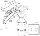
- FIG. 1is a combined pictorial view and block diagram of a video laryngoscope system for use with an endotracheal tube for intubation of a patient;
- FIG. 2is a pictorial view of a laryngoscope blade including a daisy chain of four imaging units of an image capture module of a video laryngoscope;
- FIG. 3is an enlarged view of the daisy chain of the image capture module
- FIG. 4is a schematic diagram showing three Field Of View (FOV) arrangements of the image capture module
- FIG. 5is a pictorial view of a laryngoscope handle including finger/thumb operated controls.
- FIGS. 6A to 6Cshow the use of the video laryngoscope system for assisting an intubation of a patient.
- FIGS. 1 to 5show a video laryngoscope system 100 for use with an endotracheal tube 200 and a video stylet 300 for assisting tracheal intubations of patients.
- the video laryngoscope system 100is preferably in communication with a healthcare facility computer system 400 including a healthcare facility database 401 for storing computer files 402 .
- the video laryngoscope system 100can generate patient intubation files compatible with standard Electronic Medical Record (EMR) programs.
- EMRElectronic Medical Record
- the video laryngoscope system 100can be in wired or wireless communication with the healthcare facility computer system 400 .
- the video laryngoscope system 100includes a handheld video laryngoscope 101 having a laryngoscope handle 102 and a laryngoscope blade 103 transversely extending from the laryngoscope handle 102 and terminating at a distal laryngoscope blade tip 104 .
- the laryngoscope handle 102includes a power source 106 preferably in the form of a rechargeable battery and an onboard display screen 107 .
- the laryngoscope blade 103has an underside blade surface 108 for deploying against a patient's tongue on insertion of the laryngoscope blade 103 into his mouth and an upperside blade surface 109 opposite the underside blade surface 108 .
- the video laryngoscope 101includes an image capture module 111 including stationary imaging units 112 deployed along the laryngoscope blade 103 at increasing lengths from the distal laryngoscope blade tip 104 .
- the imaging units 112are each capable of independently and simultaneously generating a real-time video stream of a patient's airway passage during an intubation for selective display on the display screen 107 .
- the video laryngoscope system 100includes a controller 113 for controlling the operation of the image capture module 111 including inter alia real-time video display during intubation procedures, real-time video recording of intubation procedures, and the like.
- the controller 113can also control the operation of the video stylet 300 .
- the controller 113is preferably in wireless communication with the video stylet 300 .
- FIG. 2shows the upperside blade surface 109 has a stepped configuration for forming an elongated guide channel 114 for supporting an endotracheal tube 200 during an intubation.
- the upperside blade surface 109includes a major blade surface 116 parallel and opposite the underside blade surface 108 , an upright blade surface 117 generally perpendicular to the major blade surface 116 and an uppermost blade surface 118 generally parallel to the major blade surface 116 and tapering theretowards.
- the image capture module 111preferably includes a so-called imaging unit daisy chain 119 of a series of at least two longitudinally spaced apart rigidly mounted imaging units 112 and in this case four imaging units 112 stationary mounted on the laryngoscope blade 103 .
- the imaging unit daisy chain 119is preferably deployed on the upright blade surface 117 . Alternatively, it can be deployed on the uppermost blade surface 118 as shown in dashed lines.
- the imaging unit daisy chain 119can be permanently or detachably mounted on the laryngoscope blade 103 .
- FIG. 2also shows a display screen 107 remote from the video laryngoscope 101 and simultaneously displaying two different real-time video streams captured by two different imaging units 112 .
- each imaging unit 112includes one or more illumination sources 121 and a digital imaging sensor 122 .
- the digital imaging sensors 122include inter alia a camera and one or more lenses.
- An exemplary wafer level CMOS camerais the 1.3M pixel camera cube from Kushan Q Technology Ltd which has a maximum diagonal FOV of 66°.
- the imaging units 122can have the same magnification and Field of View (FOV). Alternatively, the imaging units 122 can have different magnifications and FOVs.
- the image capture module 111includes at least a pair of imaging units 112 having a leading imaging unit 123 proximate the distal laryngoscope blade tip 104 and a trailing imaging unit 124 behind the leading imaging unit 123 relative to the distal laryngoscope blade tip 104 .
- the length denoted L the trailing imaging unit 124 is behind the leading imaging unit 123 relative to the distal laryngoscope blade tip 104depends on blade size and is at least 1 cm.
- FIG. 4shows three exemplary FOV arrangements as follows: First, the imaging units 123 and 124 have a non-overlapping FOV arrangement 126 . Second, the imaging units 123 and 124 have a partially overlapping FOV arrangement 127 . And third, the imaging units 123 and 124 have a fully overlapping FOV arrangement 128 with one FOV within the other FOV.
- the imaging units 123 and 124can be at different distances from the internal structures of a patient's airway passage that they are imaging at a particular location of the laryngoscope blade 103 therealong during an intubation, the leading imaging unit 123 and the trailing imaging unit 124 image different sized areas of different locations of a patient's airway passage at a particular location of the laryngoscope blade 103 .
- FIG. 5shows the controller 113 preferably includes finger/thumb operated controls 129 on the video laryngoscope 101 for enabling a clinician performing an intubation to readily operate the controller 113 to select which one or more real-time video streams he wants to view on the display screen 107 during the intubation.
- the finger/thumb operated controls 129can include inter alia push buttons, rotatable thumbscrews, and the like.
- the display screen 107can be a touchscreen for touchscreen operation. A clinician can also select to display the real time video stream from the video stylet 300 on the display screen 107 .
- a cliniciantypically selects to display the real time video stream from the video stylet 300 after the laryngoscope blade 103 is in its final blade position and the clinician has introduced the endotracheal tube 200 along the guide channel 114 thereby obstructing the blade mounted imaging units 112 .
- FIGS. 6A to 6CThe use of a video laryngoscope system 100 with a leading imaging unit 123 and a trailing imaging unit 124 is now described with reference to FIGS. 6A to 6C .
- FIG. 6Ashows that on initial blade insertion into a patient's mouth, the leading imaging unit 123 obtains a close-up view of the vallecula region of a patient while the trailing imaging unit 124 obtains a view of the patient's uvula and posterior pharynx.
- FIG. 6Bshows that as the video laryngoscope 101 is advanced down the patient's airway passage, the views obtained by the imaging units change.
- FIG. 4Bshows that as laryngoscope handle 102 is tilted upward, thereby advancing the laryngoscope blade 103 , the leading imaging unit 123 is positioned to obtain a close up view of a patient's vocal cords while the trailing imaging unit 124 is positioned to obtain a view of his interarytrnoid notch.
- FIG. 6Cshows that as the laryngoscope handle 102 is further tilted upward, thereby further advancing the laryngoscope blade 103 , the leading imaging unit 123 may be advanced so as to obtain a closer view of vocal cords of the patient, while the trailing imaging unit 124 may be positioned so as to maintain a view of the interarytrnoid notch and the esophagus thereby increasing the certainty of correct endotracheal tube placement.
Landscapes
- Health & Medical Sciences (AREA)
- Life Sciences & Earth Sciences (AREA)
- Surgery (AREA)
- Engineering & Computer Science (AREA)
- Biomedical Technology (AREA)
- Veterinary Medicine (AREA)
- Public Health (AREA)
- General Health & Medical Sciences (AREA)
- Animal Behavior & Ethology (AREA)
- Heart & Thoracic Surgery (AREA)
- Medical Informatics (AREA)
- Biophysics (AREA)
- Physics & Mathematics (AREA)
- Molecular Biology (AREA)
- Pathology (AREA)
- Optics & Photonics (AREA)
- Nuclear Medicine, Radiotherapy & Molecular Imaging (AREA)
- Radiology & Medical Imaging (AREA)
- Pulmonology (AREA)
- Otolaryngology (AREA)
- Physiology (AREA)
- Emergency Medicine (AREA)
- Anesthesiology (AREA)
- Hematology (AREA)
- Mechanical Engineering (AREA)
- Endoscopes (AREA)
Abstract
Description
Claims (17)
Applications Claiming Priority (3)
| Application Number | Priority Date | Filing Date | Title |
|---|---|---|---|
| IL22637913 | 2013-05-16 | ||
| IL226379 | 2013-05-16 | ||
| PCT/IL2014/050426WO2014184795A1 (en) | 2013-05-16 | 2014-05-15 | Video laryngoscope systems |
Related Parent Applications (1)
| Application Number | Title | Priority Date | Filing Date |
|---|---|---|---|
| PCT/IL2014/050426A-371-Of-InternationalWO2014184795A1 (en) | 2013-05-16 | 2014-05-15 | Video laryngoscope systems |
Related Child Applications (1)
| Application Number | Title | Priority Date | Filing Date |
|---|---|---|---|
| US16/792,565ContinuationUS20200178780A1 (en) | 2013-05-16 | 2020-02-17 | Video Laryngoscope Systems |
Publications (2)
| Publication Number | Publication Date |
|---|---|
| US20160095506A1 US20160095506A1 (en) | 2016-04-07 |
| US10588498B2true US10588498B2 (en) | 2020-03-17 |
Family
ID=51897843
Family Applications (2)
| Application Number | Title | Priority Date | Filing Date |
|---|---|---|---|
| US14/891,137Expired - Fee RelatedUS10588498B2 (en) | 2013-05-16 | 2014-05-15 | Video laryngoscope systems |
| US16/792,565AbandonedUS20200178780A1 (en) | 2013-05-16 | 2020-02-17 | Video Laryngoscope Systems |
Family Applications After (1)
| Application Number | Title | Priority Date | Filing Date |
|---|---|---|---|
| US16/792,565AbandonedUS20200178780A1 (en) | 2013-05-16 | 2020-02-17 | Video Laryngoscope Systems |
Country Status (5)
| Country | Link |
|---|---|
| US (2) | US10588498B2 (en) |
| EP (1) | EP2996539B1 (en) |
| AU (1) | AU2014266805B2 (en) |
| CA (1) | CA2912512C (en) |
| WO (1) | WO2014184795A1 (en) |
Cited By (4)
| Publication number | Priority date | Publication date | Assignee | Title |
|---|---|---|---|---|
| WO2021220214A1 (en)* | 2020-04-30 | 2021-11-04 | Sunildatta Krishnaji Jog | Device for simplified endotracheal intubation |
| US11206973B1 (en) | 2020-09-14 | 2021-12-28 | Kenneth Hiller | Laryngoscope |
| US11832800B2 (en) | 2022-02-09 | 2023-12-05 | Visurraga Enterprises Llc | Medical visualization and intubation systems |
| US12185923B2 (en) | 2019-03-14 | 2025-01-07 | Teleflex Medical Incorporated | Universal laryngoscope blade for both conventional handles and fiber-illuminated handles |
Families Citing this family (31)
| Publication number | Priority date | Publication date | Assignee | Title |
|---|---|---|---|---|
| US10299668B2 (en)* | 2005-10-21 | 2019-05-28 | Physio-Control, Inc. | Laryngoscope with handle-grip activated recording |
| US9913577B2 (en) | 2010-09-28 | 2018-03-13 | Obp Medical Corporation | Speculum |
| US10149957B2 (en) | 2013-10-03 | 2018-12-11 | University Of Utah Research Foundation | Tracheal intubation system including a laryngoscope |
| US10420538B2 (en) | 2015-02-05 | 2019-09-24 | Obp Medical Corporation | Illuminated surgical retractor |
| US9867602B2 (en) | 2015-02-05 | 2018-01-16 | Obp Medical Corporation | Illuminated surgical retractor |
| US9782061B2 (en) | 2015-03-04 | 2017-10-10 | Velosal Medical, Inc. | Video laryngoscopy device |
| US10939899B2 (en) | 2015-06-03 | 2021-03-09 | Obp Medical Corporation | End cap assembly for retractor and other medical devices |
| ES2968069T3 (en) | 2015-06-03 | 2024-05-07 | Obp Surgical Corp | Retractor |
| US10881387B2 (en) | 2015-06-03 | 2021-01-05 | Obp Medical Corporation | Retractor |
| CA2988923A1 (en)* | 2015-06-08 | 2016-12-15 | The General Hospital Corporation | Airway management and visualization device |
| US11166628B2 (en) | 2016-02-02 | 2021-11-09 | Physio-Control, Inc. | Laryngoscope with handle-grip activated recording |
| JP1588029S (en)* | 2016-05-13 | 2017-10-10 | ||
| JP1587914S (en)* | 2016-05-13 | 2017-10-10 | ||
| JP1588028S (en)* | 2016-05-13 | 2017-10-10 | ||
| JP1587913S (en)* | 2016-05-13 | 2017-10-10 | ||
| JP1588027S (en)* | 2016-05-13 | 2017-10-10 | ||
| US10722621B2 (en) | 2016-07-11 | 2020-07-28 | Obp Medical Corporation | Illuminated suction device |
| US10687793B2 (en) | 2017-07-18 | 2020-06-23 | Obp Medical Corporation | Minimally invasive no touch (MINT) procedure for harvesting the great saphenous vein (GSV) and venous hydrodissector and retractor for use during the MINT procedure |
| US10278572B1 (en) | 2017-10-19 | 2019-05-07 | Obp Medical Corporation | Speculum |
| US10799229B2 (en) | 2018-02-20 | 2020-10-13 | Obp Medical Corporation | Illuminated medical devices |
| EP4606345A2 (en) | 2018-02-20 | 2025-08-27 | CooperSurgical, Inc. | Illuminated medical devices |
| JP7037410B2 (en)* | 2018-03-28 | 2022-03-16 | 日本光電工業株式会社 | Intubation system |
| USD911521S1 (en) | 2019-02-19 | 2021-02-23 | Obp Medical Corporation | Handle for medical devices including surgical retractors |
| US11684251B2 (en)* | 2019-03-01 | 2023-06-27 | Covidien Ag | Multifunctional visualization instrument with orientation control |
| USD904607S1 (en) | 2019-05-07 | 2020-12-08 | Obp Medical Corporation | Nasal retractor |
| EP3854290A1 (en)* | 2020-01-24 | 2021-07-28 | Universität Zürich | Tip light laryngoscope for trans-tissue illumination |
| US10959609B1 (en) | 2020-01-31 | 2021-03-30 | Obp Medical Corporation | Illuminated suction device |
| US10966702B1 (en) | 2020-02-25 | 2021-04-06 | Obp Medical Corporation | Illuminated dual-blade retractor |
| WO2021245695A1 (en)* | 2020-06-01 | 2021-12-09 | Rajasekar Petthannan | System and method for a remote video laryngoscope |
| US20240315547A1 (en)* | 2020-12-03 | 2024-09-26 | Chih-Min Jen | Multi-view video laryngoscope, and spatula blade configured with multiple image capturing apparatuses |
| US12318080B2 (en) | 2023-07-21 | 2025-06-03 | Coopersurgical, Inc. | Illuminated surgical retractor capable of hand-held operation and of being mounted to a fixed frame |
Citations (22)
| Publication number | Priority date | Publication date | Assignee | Title |
|---|---|---|---|---|
| US5800344A (en) | 1996-10-23 | 1998-09-01 | Welch Allyn, Inc. | Video laryngoscope |
| US6139491A (en)* | 1997-11-13 | 2000-10-31 | Heine Optotechnik Gmbh & Co. Kg | Fibre-optic laryngoscope spatula with an exchangeable light-guide part |
| US6840903B2 (en)* | 2002-03-21 | 2005-01-11 | Nuvista Technology Corporation | Laryngoscope with image sensor |
| US20050279355A1 (en)* | 1999-05-04 | 2005-12-22 | Loubser Paul G | Superglottic and peri-laryngeal apparatus having video components for structural visualization and for placement of supraglottic, intraglottic, tracheal and esophageal conduits |
| US20060020171A1 (en)* | 2002-10-21 | 2006-01-26 | Gilreath Mark G | Intubation and imaging device and system |
| US20070179342A1 (en)* | 2006-01-12 | 2007-08-02 | Kb Port Llc | Wireless Laryngoscope with Internal Antennae and One Piece Construction Adapted for Laryngoscopy Training |
| US20080064926A1 (en)* | 2006-09-13 | 2008-03-13 | Tien-Sheng Chen | Laryngoscope with wireless image transmission |
| US20080177146A1 (en)* | 2007-01-19 | 2008-07-24 | Tien-Sheng Chen | Double Vision Endotracheal Tube Installation System |
| US20100081875A1 (en)* | 2003-07-15 | 2010-04-01 | EndoRobotics Inc. | Surgical Device For Minimal Access Surgery |
| US20100198009A1 (en)* | 2004-09-24 | 2010-08-05 | Vivid Medical, Inc. | Disposable endoscope and portable display |
| US20110137127A1 (en)* | 2009-12-08 | 2011-06-09 | Ai Medical Devices, Inc. | Dual screen intubation system |
| US20110263935A1 (en) | 2010-04-21 | 2011-10-27 | Chunyuan Qiu | Intubation systems and methods based on airway pattern identification |
| US20120078055A1 (en)* | 2010-09-23 | 2012-03-29 | George Berci | Video stylet with directable tip |
| US20120116156A1 (en) | 2009-04-28 | 2012-05-10 | Dror Lederman | Method and apparatus for automatic verification of endotracheal intubation |
| US20120190929A1 (en) | 2009-08-28 | 2012-07-26 | Indian Ocean Medical Inc. | Laryngoscope |
| WO2012172076A1 (en) | 2011-06-15 | 2012-12-20 | Medizinische Hochschule Hannover | Medical device for conducting a medical examination and/or intervention within a human or animal body |
| US8398545B2 (en) | 2007-01-19 | 2013-03-19 | Tien-Sheng Chen | Laryngoscope with a movable image-capturing unit |
| US8419634B2 (en)* | 2007-06-12 | 2013-04-16 | University Hospitals Of Cleveland | Apparatus and method for airway management |
| US8460184B2 (en)* | 2009-12-11 | 2013-06-11 | University Hospitals Of Cleveland | Airway management |
| US8814787B2 (en)* | 2009-04-02 | 2014-08-26 | University of Pittsburgh—of the Commonwealth System of Higher Education | Articulating laryngoscope |
| US8827899B2 (en)* | 2004-09-24 | 2014-09-09 | Vivid Medical, Inc. | Disposable endoscopic access device and portable display |
| US20150080655A1 (en)* | 2013-09-19 | 2015-03-19 | Physio-Control, Inc. | Multi-function video system |
Family Cites Families (1)
| Publication number | Priority date | Publication date | Assignee | Title |
|---|---|---|---|---|
| US20110245609A1 (en)* | 2010-03-30 | 2011-10-06 | Vadim Laser | Video adapter for laryngoscope |
- 2014
- 2014-05-15EPEP14798319.1Apatent/EP2996539B1/ennot_activeNot-in-force
- 2014-05-15WOPCT/IL2014/050426patent/WO2014184795A1/enactiveApplication Filing
- 2014-05-15CACA2912512Apatent/CA2912512C/enactiveActive
- 2014-05-15AUAU2014266805Apatent/AU2014266805B2/ennot_activeCeased
- 2014-05-15USUS14/891,137patent/US10588498B2/ennot_activeExpired - Fee Related
- 2020
- 2020-02-17USUS16/792,565patent/US20200178780A1/ennot_activeAbandoned
Patent Citations (27)
| Publication number | Priority date | Publication date | Assignee | Title |
|---|---|---|---|---|
| US5800344A (en) | 1996-10-23 | 1998-09-01 | Welch Allyn, Inc. | Video laryngoscope |
| US6139491A (en)* | 1997-11-13 | 2000-10-31 | Heine Optotechnik Gmbh & Co. Kg | Fibre-optic laryngoscope spatula with an exchangeable light-guide part |
| US20050279355A1 (en)* | 1999-05-04 | 2005-12-22 | Loubser Paul G | Superglottic and peri-laryngeal apparatus having video components for structural visualization and for placement of supraglottic, intraglottic, tracheal and esophageal conduits |
| US6840903B2 (en)* | 2002-03-21 | 2005-01-11 | Nuvista Technology Corporation | Laryngoscope with image sensor |
| US20060020171A1 (en)* | 2002-10-21 | 2006-01-26 | Gilreath Mark G | Intubation and imaging device and system |
| US20100081875A1 (en)* | 2003-07-15 | 2010-04-01 | EndoRobotics Inc. | Surgical Device For Minimal Access Surgery |
| US8827899B2 (en)* | 2004-09-24 | 2014-09-09 | Vivid Medical, Inc. | Disposable endoscopic access device and portable display |
| US20100198009A1 (en)* | 2004-09-24 | 2010-08-05 | Vivid Medical, Inc. | Disposable endoscope and portable display |
| US20070179342A1 (en)* | 2006-01-12 | 2007-08-02 | Kb Port Llc | Wireless Laryngoscope with Internal Antennae and One Piece Construction Adapted for Laryngoscopy Training |
| US20080064926A1 (en)* | 2006-09-13 | 2008-03-13 | Tien-Sheng Chen | Laryngoscope with wireless image transmission |
| US20080177146A1 (en)* | 2007-01-19 | 2008-07-24 | Tien-Sheng Chen | Double Vision Endotracheal Tube Installation System |
| US8398545B2 (en) | 2007-01-19 | 2013-03-19 | Tien-Sheng Chen | Laryngoscope with a movable image-capturing unit |
| US9326669B2 (en)* | 2007-06-12 | 2016-05-03 | University Hospitals Of Cleveland | Airway management |
| US8419634B2 (en)* | 2007-06-12 | 2013-04-16 | University Hospitals Of Cleveland | Apparatus and method for airway management |
| US8814787B2 (en)* | 2009-04-02 | 2014-08-26 | University of Pittsburgh—of the Commonwealth System of Higher Education | Articulating laryngoscope |
| US20120116156A1 (en) | 2009-04-28 | 2012-05-10 | Dror Lederman | Method and apparatus for automatic verification of endotracheal intubation |
| US9332896B2 (en)* | 2009-08-28 | 2016-05-10 | Indian Ocean Medical Inc. | Laryngoscope |
| US20120190929A1 (en) | 2009-08-28 | 2012-07-26 | Indian Ocean Medical Inc. | Laryngoscope |
| US20110137127A1 (en)* | 2009-12-08 | 2011-06-09 | Ai Medical Devices, Inc. | Dual screen intubation system |
| US8460184B2 (en)* | 2009-12-11 | 2013-06-11 | University Hospitals Of Cleveland | Airway management |
| US8894569B2 (en)* | 2010-04-21 | 2014-11-25 | Chunyuan Qiu | Intubation systems and methods based on airway pattern identification |
| US20110263935A1 (en) | 2010-04-21 | 2011-10-27 | Chunyuan Qiu | Intubation systems and methods based on airway pattern identification |
| US8652033B2 (en)* | 2010-09-23 | 2014-02-18 | Karl Storz Endovision, Inc. | Video stylet with directable tip |
| US20120078055A1 (en)* | 2010-09-23 | 2012-03-29 | George Berci | Video stylet with directable tip |
| US20140194684A1 (en)* | 2011-06-15 | 2014-07-10 | Medizinische Hochschule Hannover | Medical Device for Conducting a Medical Examination and/or Intervention Within a Human or Animal Body |
| WO2012172076A1 (en) | 2011-06-15 | 2012-12-20 | Medizinische Hochschule Hannover | Medical device for conducting a medical examination and/or intervention within a human or animal body |
| US20150080655A1 (en)* | 2013-09-19 | 2015-03-19 | Physio-Control, Inc. | Multi-function video system |
Non-Patent Citations (1)
| Title |
|---|
| European Search Report issued in European Patent Application No. 14798319.1 dated Jan. 11, 2017. |
Cited By (6)
| Publication number | Priority date | Publication date | Assignee | Title |
|---|---|---|---|---|
| US12185923B2 (en) | 2019-03-14 | 2025-01-07 | Teleflex Medical Incorporated | Universal laryngoscope blade for both conventional handles and fiber-illuminated handles |
| WO2021220214A1 (en)* | 2020-04-30 | 2021-11-04 | Sunildatta Krishnaji Jog | Device for simplified endotracheal intubation |
| US11206973B1 (en) | 2020-09-14 | 2021-12-28 | Kenneth Hiller | Laryngoscope |
| USD986416S1 (en) | 2020-09-14 | 2023-05-16 | Kenneth Hiller | Laryngoscope |
| USD1068073S1 (en) | 2020-09-14 | 2025-03-25 | Kenneth Hiller | Laryngoscope |
| US11832800B2 (en) | 2022-02-09 | 2023-12-05 | Visurraga Enterprises Llc | Medical visualization and intubation systems |
Also Published As
| Publication number | Publication date |
|---|---|
| CA2912512C (en) | 2020-01-07 |
| EP2996539A1 (en) | 2016-03-23 |
| US20160095506A1 (en) | 2016-04-07 |
| AU2014266805B2 (en) | 2017-06-15 |
| EP2996539A4 (en) | 2017-02-08 |
| AU2014266805A1 (en) | 2015-12-10 |
| EP2996539B1 (en) | 2020-10-14 |
| US20200178780A1 (en) | 2020-06-11 |
| CA2912512A1 (en) | 2014-11-20 |
| WO2014184795A1 (en) | 2014-11-20 |
Similar Documents
| Publication | Publication Date | Title |
|---|---|---|
| US20200178780A1 (en) | Video Laryngoscope Systems | |
| US8652033B2 (en) | Video stylet with directable tip | |
| Berkow et al. | The technology of video laryngoscopy | |
| US9949629B2 (en) | Endotracheal tube insertion device | |
| US5951461A (en) | Image-guided laryngoscope for tracheal intubation | |
| CN102573608B (en) | Laryngoscope | |
| US20150313445A1 (en) | System and Method of Scanning a Body Cavity Using a Multiple Viewing Elements Endoscope | |
| US20070173697A1 (en) | Combined flexible and rigid intubating video laryngoscope | |
| US9867956B2 (en) | Medical device for conducting a medical examination and/or intervention within a human or animal body | |
| KR20200088321A (en) | Multifunctional visualization device | |
| JP2008528131A (en) | Video-assisted laryngeal mask airway device | |
| JP6611704B2 (en) | Guided endotracheal intubation system | |
| US20050043590A1 (en) | Laryngoscope with image sensor | |
| US20130066151A1 (en) | Tracheal Intubation Device | |
| US20160250432A1 (en) | Method and apparatus for multi-camera intubation | |
| WO2008157170A4 (en) | Airway management | |
| JP2018507091A (en) | Endotracheal tube insertion device | |
| TW201821118A (en) | Endotracheal intubation system | |
| TW201703721A (en) | Egg shaped colonoscopy and the marching control method | |
| WO2020129076A1 (en) | Portable automated dynamic linearity fibreless video endoscopy devices | |
| CN109602383A (en) | A kind of multifunctional intellectual bronchoscopy system | |
| TWM493389U (en) | Tracheal intubation device | |
| Doyle | Video laryngoscopes and video-assisted airway management |
Legal Events
| Date | Code | Title | Description |
|---|---|---|---|
| AS | Assignment | Owner name:TRUPHATEK INTERNATIONAL LTD., ISRAEL Free format text:ASSIGNMENT OF ASSIGNORS INTEREST;ASSIGNORS:DAN, GABRIEL;ROSENBLATT, DAVID;REEL/FRAME:037785/0451 Effective date:20160218 | |
| STPP | Information on status: patent application and granting procedure in general | Free format text:DOCKETED NEW CASE - READY FOR EXAMINATION | |
| STPP | Information on status: patent application and granting procedure in general | Free format text:NON FINAL ACTION MAILED | |
| STPP | Information on status: patent application and granting procedure in general | Free format text:NOTICE OF ALLOWANCE MAILED -- APPLICATION RECEIVED IN OFFICE OF PUBLICATIONS | |
| ZAAA | Notice of allowance and fees due | Free format text:ORIGINAL CODE: NOA | |
| ZAAB | Notice of allowance mailed | Free format text:ORIGINAL CODE: MN/=. | |
| STPP | Information on status: patent application and granting procedure in general | Free format text:PUBLICATIONS -- ISSUE FEE PAYMENT RECEIVED | |
| STPP | Information on status: patent application and granting procedure in general | Free format text:PUBLICATIONS -- ISSUE FEE PAYMENT VERIFIED | |
| STCF | Information on status: patent grant | Free format text:PATENTED CASE | |
| AS | Assignment | Owner name:TELEFLEX LIFE SCIENCES PTE LTD., SINGAPORE Free format text:NUNC PRO TUNC ASSIGNMENT;ASSIGNOR:TRUPHATEK INTERNATIONAL LTD.;REEL/FRAME:063817/0254 Effective date:20230524 | |
| FEPP | Fee payment procedure | Free format text:MAINTENANCE FEE REMINDER MAILED (ORIGINAL EVENT CODE: REM.); ENTITY STATUS OF PATENT OWNER: LARGE ENTITY | |
| LAPS | Lapse for failure to pay maintenance fees | Free format text:PATENT EXPIRED FOR FAILURE TO PAY MAINTENANCE FEES (ORIGINAL EVENT CODE: EXP.); ENTITY STATUS OF PATENT OWNER: LARGE ENTITY | |
| STCH | Information on status: patent discontinuation | Free format text:PATENT EXPIRED DUE TO NONPAYMENT OF MAINTENANCE FEES UNDER 37 CFR 1.362 | |
| FP | Lapsed due to failure to pay maintenance fee | Effective date:20240317 |