US10588238B2 - Apparatus, system, and method for partitioning a storage-system chassis - Google Patents
Apparatus, system, and method for partitioning a storage-system chassisDownload PDFInfo
- Publication number
- US10588238B2 US10588238B2US15/708,069US201715708069AUS10588238B2US 10588238 B2US10588238 B2US 10588238B2US 201715708069 AUS201715708069 AUS 201715708069AUS 10588238 B2US10588238 B2US 10588238B2
- Authority
- US
- United States
- Prior art keywords
- storage
- chassis
- drive
- system partition
- carrierless
- Prior art date
- Legal status (The legal status is an assumption and is not a legal conclusion. Google has not performed a legal analysis and makes no representation as to the accuracy of the status listed.)
- Expired - Fee Related
Links
- 238000000034methodMethods0.000titleclaimsabstractdescription12
- 238000000638solvent extractionMethods0.000titleabstractdescription5
- 238000005192partitionMethods0.000claimsabstractdescription163
- 238000003860storageMethods0.000claimsabstractdescription119
- 229920003051synthetic elastomerPolymers0.000claimsdescription29
- 239000005061synthetic rubberSubstances0.000claimsdescription29
- 239000004033plasticSubstances0.000claimsdescription24
- 238000001746injection mouldingMethods0.000claimsdescription5
- 239000002184metalSubstances0.000claimsdescription5
- 238000000465mouldingMethods0.000claimsdescription4
- 230000007246mechanismEffects0.000description18
- 230000006870functionEffects0.000description8
- 239000000463materialSubstances0.000description5
- 238000013500data storageMethods0.000description4
- 230000014759maintenance of locationEffects0.000description3
- 238000004519manufacturing processMethods0.000description3
- 238000012986modificationMethods0.000description3
- 230000004048modificationEffects0.000description3
- 230000000717retained effectEffects0.000description3
- 239000003086colorantSubstances0.000description2
- 239000012050conventional carrierSubstances0.000description2
- 238000001816coolingMethods0.000description2
- 229920001971elastomerPolymers0.000description2
- 238000002955isolationMethods0.000description2
- 239000005060rubberSubstances0.000description2
- 230000035939shockEffects0.000description2
- 239000011359shock absorbing materialSubstances0.000description2
- 239000007787solidSubstances0.000description2
- 230000008867communication pathwayEffects0.000description1
- 239000004020conductorSubstances0.000description1
- 238000010586diagramMethods0.000description1
- 238000009826distributionMethods0.000description1
- 238000005516engineering processMethods0.000description1
- 230000003203everyday effectEffects0.000description1
- 239000003562lightweight materialSubstances0.000description1
- 230000003287optical effectEffects0.000description1
- 230000008569processEffects0.000description1
- 238000011084recoveryMethods0.000description1
- 230000001105regulatory effectEffects0.000description1
- 238000012360testing methodMethods0.000description1
- 238000012546transferMethods0.000description1
Images


Classifications
- H—ELECTRICITY
- H05—ELECTRIC TECHNIQUES NOT OTHERWISE PROVIDED FOR
- H05K—PRINTED CIRCUITS; CASINGS OR CONSTRUCTIONAL DETAILS OF ELECTRIC APPARATUS; MANUFACTURE OF ASSEMBLAGES OF ELECTRICAL COMPONENTS
- H05K7/00—Constructional details common to different types of electric apparatus
- H05K7/14—Mounting supporting structure in casing or on frame or rack
- H05K7/1485—Servers; Data center rooms, e.g. 19-inch computer racks
- H05K7/1488—Cabinets therefor, e.g. chassis or racks or mechanical interfaces between blades and support structures
- H05K7/1489—Cabinets therefor, e.g. chassis or racks or mechanical interfaces between blades and support structures characterized by the mounting of blades therein, e.g. brackets, rails, trays
- G—PHYSICS
- G11—INFORMATION STORAGE
- G11B—INFORMATION STORAGE BASED ON RELATIVE MOVEMENT BETWEEN RECORD CARRIER AND TRANSDUCER
- G11B33/00—Constructional parts, details or accessories not provided for in the other groups of this subclass
- G11B33/12—Disposition of constructional parts in the apparatus, e.g. of power supply, of modules
- G11B33/125—Disposition of constructional parts in the apparatus, e.g. of power supply, of modules the apparatus comprising a plurality of recording/reproducing devices, e.g. modular arrangements, arrays of disc drives
- G11B33/126—Arrangements for providing electrical connections, e.g. connectors, cables, switches
- G—PHYSICS
- G11—INFORMATION STORAGE
- G11B—INFORMATION STORAGE BASED ON RELATIVE MOVEMENT BETWEEN RECORD CARRIER AND TRANSDUCER
- G11B33/00—Constructional parts, details or accessories not provided for in the other groups of this subclass
- G11B33/12—Disposition of constructional parts in the apparatus, e.g. of power supply, of modules
- G11B33/125—Disposition of constructional parts in the apparatus, e.g. of power supply, of modules the apparatus comprising a plurality of recording/reproducing devices, e.g. modular arrangements, arrays of disc drives
- G11B33/127—Mounting arrangements of constructional parts onto a chassis
- G11B33/128—Mounting arrangements of constructional parts onto a chassis of the plurality of recording/reproducing devices, e.g. disk drives, onto a chassis
- G—PHYSICS
- G11—INFORMATION STORAGE
- G11B—INFORMATION STORAGE BASED ON RELATIVE MOVEMENT BETWEEN RECORD CARRIER AND TRANSDUCER
- G11B33/00—Constructional parts, details or accessories not provided for in the other groups of this subclass
- G11B33/14—Reducing influence of physical parameters, e.g. temperature change, moisture, dust
- G11B33/1406—Reducing the influence of the temperature
- G11B33/1413—Reducing the influence of the temperature by fluid cooling
- G11B33/142—Reducing the influence of the temperature by fluid cooling by air cooling
- H—ELECTRICITY
- H05—ELECTRIC TECHNIQUES NOT OTHERWISE PROVIDED FOR
- H05K—PRINTED CIRCUITS; CASINGS OR CONSTRUCTIONAL DETAILS OF ELECTRIC APPARATUS; MANUFACTURE OF ASSEMBLAGES OF ELECTRICAL COMPONENTS
- H05K7/00—Constructional details common to different types of electric apparatus
- H05K7/14—Mounting supporting structure in casing or on frame or rack
- H05K7/1485—Servers; Data center rooms, e.g. 19-inch computer racks
- H05K7/1487—Blade assemblies, e.g. blade cases or inner arrangements within a blade
- H—ELECTRICITY
- H05—ELECTRIC TECHNIQUES NOT OTHERWISE PROVIDED FOR
- H05K—PRINTED CIRCUITS; CASINGS OR CONSTRUCTIONAL DETAILS OF ELECTRIC APPARATUS; MANUFACTURE OF ASSEMBLAGES OF ELECTRICAL COMPONENTS
- H05K7/00—Constructional details common to different types of electric apparatus
- H05K7/20—Modifications to facilitate cooling, ventilating, or heating
- H05K7/20709—Modifications to facilitate cooling, ventilating, or heating for server racks or cabinets; for data centers, e.g. 19-inch computer racks
- H05K7/20718—Forced ventilation of a gaseous coolant
- H05K7/20727—Forced ventilation of a gaseous coolant within server blades for removing heat from heat source
Definitions
- a storage driveis typically removably secured within the storage-system chassis using a carrier mechanism that is attached to the storage drive.
- carrier mechanismsmay present unwanted limitations. For example, conventional carrier mechanisms may occupy significant amounts of space within a storage-system chassis that may be needed for cooling functions and/or that could have otherwise been used for additional storage drives. Additionally, conventional carrier mechanisms may add significant amounts of weight to a storage-system chassis and/or add significant amounts of time to storage-drive servicing tasks.
- a multi-purpose storage-system partitionmay include (1) a bottom that includes a keyhole fastener that is configured to (a) interlock with one of a plurality of keyhole openings of a removable drive-plane board having a front plurality of storage-drive connectors and a rear plurality of storage-drive connectors and (b) retain the removable drive-plane board within a storage-system chassis, (2) a front that includes a front plurality of storage-drive contact points configured to (a) retain a front plurality of carrierless storage drives within the storage-system chassis and (b) align the front plurality of carrierless storage drives with the front plurality of storage-drive connectors, (3) a rear that includes a rear plurality of storage-drive contact points configured to (a) retain a rear plurality of carrierless storage drives within the storage-system chassis and (b) align the rear plurality of carrierless storage drives with the rear plurality
- the front plurality of storage-drive contact pointsmay be configured to dampen movements of the front plurality of carrierless storage drives relative to movements of the storage-system chassis
- the rear plurality of storage-drive contact pointsmay be configured to dampen movements of the rear plurality of carrierless storage drives relative to the movements of the storage-system chassis.
- the front of the multi-purpose storage-system partitionmay be a multi-shot injection-molded part that includes a substantially rigid plastic portion and a synthetic rubber portion, and the front plurality of storage-drive contact points may be formed from the synthetic rubber portion.
- the rear of the multi-purpose storage-system partitionmay be a multi-shot injection-molded part that includes a substantially rigid plastic portion and a synthetic rubber portion, and the rear plurality of storage-drive contact points may be formed from the synthetic rubber portion.
- the multi-purpose storage-system partitionmay include a multi-shot injection-molded part that includes a substantially rigid plastic portion and a synthetic rubber portion, and the keyhole fastener may be formed from the substantially rigid plastic portion. Additionally or alternatively, the multi-purpose storage-system partition may include an injection-molded part and a metal bracket coupled to the injection-molded part and configured to stiffen the multi-purpose storage-system partition.
- the storage-system chassismay include a front through which air may be able to pass and a rear through which air may be able to pass and a fan coupled to the storage-system chassis that directs an airflow through the storage-system chassis from the front of the storage-system chassis to the rear of the storage-system chassis.
- the multi-purpose storage-system partitionmay include openings through which the airflow is able to pass.
- the openingsmay be slits, and each of the slits may be located between two of the front storage-drive contact points and configured to allow a portion of the airflow to flow between two of the front plurality of carrierless storage drives and two of the rear plurality of carrierless storage drives.
- the multi-purpose storage-system partitionmay include an additional plurality of keyhole openings, and each of the additional plurality of keyhole openings may be configured to interlock with a keyhole fastener of a drive-unseating member.
- a corresponding storage-system drawermay include (1) a chassis, (2) a removeable drive-plane board that includes (a) a plurality of keyhole openings, (b) a front plurality of storage-drive connectors, and (c) a rear plurality of storage-drive connectors, and (3) a multi-purpose storage-system partition coupled to the chassis that includes (a) a bottom that includes a keyhole fastener that is oriented downward relative to the chassis and configured to (i) interlock with one of the plurality of keyhole openings of the removable drive-plane board and (ii) retain the removable drive-plane board within the chassis, (b) a front that includes a front plurality of storage-drive contact points configured to (i) retain a front plurality of carrierless storage drives within the chassis and (ii) align the front plurality of carrierless storage drives with the front plurality of storage-drive connectors, and (c) a rear that includes a rear plurality of storage-drive contact points configured to (i) retain a
- the front plurality of storage-drive contact pointsmay be configured to dampen movements of the front plurality of carrierless storage drives relative to movements of the chassis
- the rear plurality of storage-drive contact pointsmay be configured to dampen movements of the rear plurality of carrierless storage drives relative to the movements of the chassis.
- the front of the multi-purpose storage-system partitionmay be a multi-shot injection-molded part that includes a substantially rigid plastic portion and a synthetic rubber portion, and the front plurality of storage-drive contact points may be formed from the synthetic rubber portion.
- the rear of the multi-purpose storage-system partitionmay be a multi-shot injection-molded part that includes a substantially rigid plastic portion and a synthetic rubber portion, and the rear plurality of storage-drive contact points may be formed from the synthetic rubber portion.
- the multi-purpose storage-system partitionmay include a multi-shot injection-molded part that includes a substantially rigid plastic portion and a synthetic rubber portion, and the keyhole fastener may be formed from the substantially rigid plastic portion.
- the multi-purpose storage-system partitionmay include an injection-molded part and a metal bracket coupled to the injection-molded part and configured to stiffen the multi-purpose storage-system partition.
- the multi-purpose storage-system partitionmay include a side having a fastener-retaining member
- the storage-system drawermay include a fastener that may be configured to engage the fastener-retaining member and couple the multi-purpose storage-system partition to a side of the chassis.
- the chassismay include a front through which air may be able to pass and a rear through which air may be able to pass
- the storage-system drawermay include a fan coupled to the chassis that directs an airflow through the chassis from the front of the chassis to the rear of the chassis
- the multi-purpose storage-system partitionmay include at least one opening through which the airflow may be able to pass.
- the at least one openingmay include a plurality of slits, and each of the plurality of slits may be located between two of the front storage-drive contact points and configured to allow a portion of the airflow to flow between two of the front plurality of carrierless storage drives and two of the rear plurality of carrierless storage drives.
- the multi-purpose storage-system partitionmay include an additional plurality of keyhole openings, and each of the additional plurality of keyhole openings may be configured to interlock with a keyhole fastener of a drive-unseating member.
- a methodmay include (1) molding, as part of a multi-shot injection-molding process, a first portion of a multi-purpose storage-system partition from a substantially rigid plastic and (2) molding, as part of the multi-shot injection-molding process, a second portion of the multi-purpose storage-system partition from a synthetic rubber.
- the first portion of the multi-purpose storage-system partitionmay include a bottom that includes a keyhole fastener configured to interlock with one of a plurality of keyhole openings of a removable drive-plane board having a plurality of storage-drive connectors and retain the removable drive-plane board within a storage-system chassis
- the second portion of the multi-purpose storage-system partitionmay include a plurality of storage-drive contact points configured to retain a plurality of carrierless storage drives within the storage-system chassis and align the plurality of carrierless storage drives with the plurality of storage-drive connectors.
- FIG. 1is a top view of an exemplary removable drive-plane board.
- FIG. 2is a bottom view of the exemplary removable drive-plane board illustrated in FIG. 1 .
- FIG. 3is a perspective view of the exemplary removable drive-plane board illustrated in FIG. 1 in a disconnected state.
- FIG. 4is a perspective view of exemplary storage-system drives and storage-system modules.
- FIG. 5is a perspective view of an exemplary storage-system drawer.
- FIG. 6is a perspective view of an exemplary data-center rack with several storage-system drawers.
- FIG. 7is a bottom view of the exemplary storage-system drawer illustrated in FIG. 5 .
- FIG. 8is a simplified perspective view of the exemplary storage-system drawer illustrated in FIG. 5 with exemplary multi-purpose storage-system partitions.
- FIG. 9is a simplified top view of the exemplary storage-system drawer illustrated in FIG. 5 showing another view of the exemplary multi-purpose storage-system partitions illustrated in FIG. 8 .
- FIG. 10is a close-up top view of one of the exemplary multi-purpose storage-system partitions illustrated in FIG. 8 .
- FIG. 11is a perspective view of two of the exemplary multi-purpose storage-system partitions illustrated in FIG. 8 while retaining storage drives.
- FIG. 12is a perspective view of the exemplary multi-purpose storage-system partitions illustrated in FIG. 11 without the storage drives.
- FIG. 13is a front view of one of the exemplary multi-purpose storage-system partitions illustrated in FIG. 8 .
- FIG. 14is a perspective view of a front of one of the exemplary multi-purpose storage-system partitions illustrated in FIG. 8 .
- FIG. 15is a rear view of one of the exemplary multi-purpose storage-system partitions illustrated in FIG. 8 .
- FIG. 16is a perspective view of a rear of one of the exemplary multi-purpose storage-system partitions illustrated in FIG. 8 .
- FIG. 17is a perspective view of exemplary storage-drive contact points.
- FIG. 18is a front view of the exemplary storage-drive contact points illustrated in FIG. 17 .
- FIG. 19is a bottom view of one of the exemplary multi-purpose storage-system partitions illustrated in FIG. 8 .
- FIG. 20is an exploded view of one of the exemplary multi-purpose storage-system partitions illustrated in FIG. 8 .
- FIG. 21is a front view of a portion of one of the exemplary multi-purpose storage-system partitions illustrated in FIG. 8 .
- FIG. 22is a close-up view of an exemplary keyhole opening interlocked with an exemplary keyhole fastener.
- FIG. 23is a flow diagram of an exemplary method for manufacturing a multi-purpose storage-system partition.
- FIG. 24is a close-up perspective view of an exemplary light pipe.
- the present disclosureis generally directed to systems and methods for partitioning a storage-system chassis.
- the multi-purpose storage-system partitions disclosed hereinmay be used in a storage-system chassis to (1) secure carrierless storage drives within the storage-system chassis, (2) provide structural support for the storage-system chassis, and/or (3) provide attachment points for other removable storage-system components, such as a removable drive-plane board, within the storage-system chassis.
- the multi-purpose storage-system partitions disclosed hereinmay be lightweight double-shot injection-molded partitions that include rubber contact points that securely position carrierless storage drives within the storage-system chassis and provide shock and vibration dampening and isolation for the carrierless storage drives.
- the multi-purpose storage-system partitions disclosed hereinmay also include vertical openings that allow air to pass through the storage-system chassis and through the storage drives secured by the multi-purpose storage-system partitions.
- Embodiments of the instant disclosuremay provide various features and advantages over conventional storage-drive retention mechanisms.
- the multi-purpose storage-system partitions disclosed hereinmay offer weight, space, and service-time savings over conventional storage-retention mechanisms by enabling storage drives to be removably secured within a storage-system chassis without a need for carrier mechanisms to be attached to the storage drives.
- the multi-purpose storage-system partitions disclosed hereinmay offer additional weight and space savings over conventional storage-drive retention mechanisms by performing both storage-drive retention functions and structural-support functions within a storage-system chassis.
- FIGS. 1-4detailed descriptions of an example removable drive-plane board.
- Detailed descriptions of an example storage-system drawerwill be provided in connection with FIGS. 5-7 .
- Detailed descriptions of example multi-purpose storage-system partitionswill be provided in connection with FIGS. 8-22 and 24 .
- Detailed descriptions of an example method for manufacturing a multi-purpose storage-system partitionwill be provided in connection with FIG. 23 .
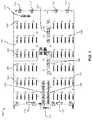
- FIG. 1shows a top view of an example removable drive-plane board 100 .
- Drive-plane board 100generally represents any structure that is adapted to connect the various active components (e.g., compute modules, storage drives, storage-controller modules, and input/output modules) that make up a storage system and/or secure the components within a chassis.
- active componentse.g., compute modules, storage drives, storage-controller modules, and input/output modules
- drive-plane board 100may be one or more printed circuit boards (PCBs) that include various connectors that are electrically connected by conductive traces.
- drive-plane board 100may be configured to support up to 72 storage drives, up to four fans, drive power control, sensors (e.g., temperature sensors or drawer open sensors), and power distribution.
- sensorse.g., temperature sensors or drawer open sensors
- drive-plane board 100may have a top 102 on which are mounted various types of connectors.
- top 102may include 72 storage-drive connectors 104 , two compute-module connectors 106 , two storage-controller connectors 108 , two I/O-module connectors 110 , four fan module connectors 112 , a front-panel connector 114 , and a power connector 116 .
- drive-plane board 100may include electrical conductors that electrically connect some or all of the connectors shown in FIG. 1 .
- Each of storage-drive connectors 104may be configured to interface with a single storage drive, such as one of storage drives 402 illustrated in FIG. 4 .
- the term “storage drive,” as used herein,generally refers to any device capable of storing electronic data.
- storage-drive connectors 104may be configured to interface with solid state drives, hard disk drives, and/or optical drives.
- storage-drive connectors 104may be configured to interface with two or more different types of storage drives.
- storage-drive connectors 104may be configured to interface with storage drives that have different physical form factors, that are made up of different types of storage (e.g., solid state or hard disk), that use different protocols, and/or that use different types of connectors.
- storage-drive connectors 104may be configured to interface with Serial Attached Small computer system interface (SAS) drives, Serial Advanced Technology Attachment (SATA) drives, and/or Non-Volatile Memory express (NVMe) drives.
- SASSerial Attached Small computer system interface
- SATASerial Advanced Technology Attachment
- NVMeNon-Volatile Memory express
- storage-drive connectors 104may be configured to enable hot-swapping of storage drives.
- Each of compute-module connectors 106may be configured to interface with a compute module, such as one of compute modules 408 in FIG. 4 .
- the term “compute module,” as used herein,generally refers to any server module whose primary function is computational and/or any server module whose primary function is to provide data storage services. In some examples, compute-module connectors 106 may be configured to interface with two or more different types of compute modules.
- Each of storage-controller connectors 108may be configured to interface with a storage-controller module, such as one of storage-controller modules 410 in FIG. 4 .
- storage-controller modulegenerally refers to any storage-system module whose primary function is to control and communicate with storage drives.
- I/O-module connectors 110may be configured to interface with an I/O module, such as one of I/O modules 412 in FIG. 4 .
- I/O modulegenerally refers to any storage-system module whose primary function is to facilitate data transfer in and out of a storage system.
- drive-plane board 100may include keyhole openings 105 that are configured to interlock with keyhole fasteners of one or more multi-purpose storage-system partitions, such as multi-purpose storage-system partitions 800 in FIG. 8 , that are contained within a storage-system chassis within which drive-plane board 100 may be removably installed.
- Drive-plane board 100may have few additional elements other than those illustrated in FIG. 1 .
- a bottom 202 of drive-plane board 100may include holes 204 that are sized to receive screws (e.g., screws 702 shown in FIG.
- drive-board 100may be made up of one or more separable pieces.
- drive-board 100may include front PCB 302 and a rear PCB 304 that may be electrically coupled via high-speed connectors 306 - 312 .
- high-speed connectors 306 - 312may provide power and communication pathways between the components of front PCB 302 and the components of rear PCB 304 .
- FIG. 5shows a perspective view of a storage-system drawer 500 .
- storage-system drawergenerally refers to any structure that is adapted to house the various components that make up a storage system.
- storage-system drawer 500may include a chassis (e.g., a metallic enclosure) made up of a front 502 , a left side 504 , a rear 506 , and a right side 508 .
- the chassis of storage-system drawer 500may be adapted to be housed in a data-center rack 600 as illustrated in FIG. 6 .
- storage-system drawer 500may be positioned on a support tray (such as support tray 602 ) coupled to a frame 604 of data-center rack 600 .
- data-center rackgenerally refers to any multi-system chassis structure for housing multiple storage-system drawers and chassis and/or providing support for one or more cables that connect to the storage-system drawers and chassis.
- a data-center rackmay also contain power supplies, network switches, and/or battery backup units.
- storage-system drawer 500may include slide mechanisms (e.g., drawer-slide mechanism 510 ) that are coupled to left side 504 and right side 508 and enable storage-system drawer 500 to be fully extended out of data-center rack 600 for servicing.
- storage-system drawer 500may include pull-handle 512 and pull-handle 514 configured to enable a technician to easily pull storage-system drawer 500 out from and return storage-system drawer 500 to data-center rack 600 .
- the chassis of storage-system drawer 500may be sized to house all of the storage-system components illustrated in FIG. 4 .
- storage-system drawer 500may be configured so that most of the storage-system components that are contained within storage-system drawer 500 may be serviced through the top side of storage-system drawer 500 .
- each storage drive contained in storage-system drawer 500may be secured within storage-system drawer 500 via a latch (e.g., a latch 528 ) adapted to hold the storage drive in place when closed and enable removal of the storage drive when open.
- a latche.g., a latch 528
- storage-system drawer 500may include one or more removable covers (e.g., removable covers 520 , 522 , 524 , and 526 ) that cover and provide access to other components contained within storage-system drawer 500 , such as a compute module, a storage-controller card, and/or cables.
- removable coverse.g., removable covers 520 , 522 , 524 , and 526 .
- storage-system drawer 500may be configured so that some of the storage-system components that are contained within storage-system drawer 500 may be serviced through the front, the bottom, or the rear of storage-system drawer 500 .
- storage-system drawer 500may include a fan module 516 and a fan module 518 removably attached to rear 506 .
- fan module 516 and fan module 518may include one or more fans that pull an airflow rearward through the chassis of storage-system drawer 500 for the purpose of cooling the storage-system components housed within storage-system drawer 500 .
- FIG. 7shows a bottom view of an open bottom 704 of storage-system drawer 500 with drive-plane board 100 installed.
- keyhole fasteners 700 and screws 702may retain drive-plane board 100 within storage-system drawer 500 .
- a close-up view of this interlocked positionis shown in FIG. 22 .
- Screws 702may be configured to screw into screw holes of one or more multi-purpose storage-system partitions, such as multi-purpose storage-system partitions 800 shown in FIG. 8 , and align the multi-purpose storage-system partitions, and the storage drives they retain, with drive-plane board 100 and storage-drive connectors 104 .
- screws 702may be thumbscrews.
- keyhole fasteners 700may be part of several multi-purpose storage-system partitions, such as multi-purpose storage-system partitions 800 shown in FIG. 8 , that are coupled to the chassis of storage-system drawer 500 .
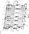
- FIG. 8shows a simplified perspective view of storage-system drawer 500 .
- storage-system drawer 500may include several multi-purpose storage-system partitions 800 .
- Each of multi-purpose storage-system partitions 800may be adapted to perform several functions within storage-system drawer 500 .
- each of multi-purpose storage-system partitions 800may include one or more of keyhole fasteners 700 that are configured to interlock with keyhole openings 105 of drive-plane board 100 .
- each of multi-purpose storage-system partitions 800may include storage-drive contact points that are adapted to retain carrierless storage drives within storage-system drawer 500 .
- each of multi-purpose storage-system partitions 800may be adapted to retain one side of six front storage drives and one side of six rear storage drives.
- storage-system drawer 500may include chassis partitions 802 and 804 that partition the chassis of storage-system drawer 500 into several compartments.
- each of left side 504 , right side 508 , chassis partition 802 , and chassis partition 804may include counterbore screw holes, such as counterbore screw holes 806 and 808 , that are spaced to ensure that each of multi-purpose storage-system partitions 800 are properly spaced within storage-system drawer 500 and properly aligned to drive-plane board 100 to allow for proper fittings of storage drives 402 .
- each of multi-purpose storage-system partitions 800may be coupled, via custom shoulder screws, to a side of the chassis of storage-system drawer 501 and one of chassis partitions 802 and 804 .
- multi-purpose storage-system partitions 800may provide structural support for the chassis of storage-system drawer 500 .
- multi-purpose storage-system partitions 800may be made from light weight materials, such as light-weight plastic.
- FIGS. 9 and 10show a simplified top view of storage-system drawer 500 and a close-up view of the top view of storage-system drawer 500 , respectively.
- the positions of multi-purpose storage-system partitions 800may be seen in relation to drive-plane board 100 .
- multi-purpose storage-system partition 800may be coupled to right side 508 of storage-system drawer 500 and chassis partition 804 .
- Multi-purpose storage-system partition 800may include storage-drive contact points 1002 that are configured to align carrierless storage drives with storage-drive connectors 104 of drive-plane board 100 , as shown.
- multi-purpose storage-system partition 800may be formed from translucent material and may glow to serve as an indicator of the state of one or more of the storage drives retained by multi-purpose storage-system partition 800 .
- multi-purpose storage-system partition 800may include an indicator, such as indicator 1004 , that may act as a conspicuous indicator of the state of an adjacent storage drive.
- all or a portion of indicator 1004may be formed from a transparent or translucent material to allow light from a light-emitting diode (LED) to pass through the indicator.
- Indicator 1004may be part of or be positioned at a distal end of a light pipe (e.g., one of light pipes 2018 illustrated in FIGS.
- an LEDmay be positioned at a proximal end of the light pipe.
- Multi-colored LEDsmay be used to cause the indicator to glow different colors to indicate different states (e.g., green may indicate that a drive is fully operational, amber may indicate that a drive needs to be serviced, etc.).
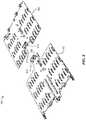
- FIGS. 11 and 12show perspective views of a multi-purpose storage-system partition 800 A and a multi-purpose storage-system partition 800 B.
- multi-purpose storage-system partition 800 A and multi-purpose storage-system partition 8008are shown retaining six storage drives.
- six latch mechanisms, such as latch 528are attached to multi-purpose storage-system partition 800 B and retain the top sides of the storage drives.
- each of multi-purpose storage-system partition 800 A and multi-purpose storage-system partition 8008may include several contact points, such as contact points 1002 , that retain the front and back of each of the storage drives.
- one or more drive-unseating mechanismssuch as drive-unseating mechanism 1200 in FIG.
- latch 528may lift drive-unseating mechanism 1200 that may be positioned under storage drive 402 , and drive-unseating mechanism 1200 may lift storage drive 402 sufficiently high enough to unseat storage drive 402 from its corresponding storage-drive connector 104 .
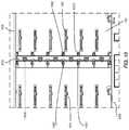
- FIGS. 13 and 14show a front view and a perspective view of a front 1300 of a multi-purpose storage-system partition 800 , respectively.
- front 1300may include various storage-drive contact points for retaining carrierless storage drives (e.g., standard storage drives without any additional carrier mechanisms) within storage-system drawer 500 .
- storage-drive contact points 1302 - 1308may be adapted to contact and retain the front and back of one side of a storage drive.
- storage-drive contact points 1310 - 1316may be adapted to contact and retain the front and back of one side of another storage drive.
- storage-drive contact points 1302 - 1308may be spaced to easily accept a storage drive and/or prevent the storage drive from moving relative to multi-purpose storage-system partition 800 .
- Storage-drive contact points 1302 - 1308may also apply a clamping force to the storage-drive and/or may dampen the motion of the storage drive relative to multi-purpose storage-system partition 800 and storage-system drawer 500 .
- Storage-drive contact points 1302 - 1316may be made of any suitable material.
- storage-drive contact points 1302 - 1316may be made of suitable shock-absorbing material, such as a synthetic rubber.
- front 1300 of multi-purpose storage-system partition 800may include various holes and/or openings.
- multi-purpose storage-system partition 800may include keyhole openings 1318 and 1320 configured to receive and retain a drive-unseating mechanism (e.g., drive-unseating mechanism 1200 in FIG. 12 ).
- Multi-purpose storage-system partition 800may also include vents 1322 and 1324 that enable air to pass through multi-purpose storage-system partition 800 , the storage drives retained by multi-purpose storage-system partition 800 , and storage-system drawer 500 .
- multi-purpose storage-system partition 800may include various features for helping a technician align storage drives with the contact points of multi-purpose storage-system partition 800 .
- multi-purpose storage-system partition 800may include alignment protrusions, such as protrusions 1326 and 1328 , located above each contact point of multi-purpose storage-system partition 800 . In some examples, these protrusions may help align a storage drive to multi-purpose storage-system partition 800 as it is being inserted into storage-system drawer 500 .
- multi-purpose storage-system partition 800may also include three keyhole fasteners 700 that may be configured to retain removable drive-plane board 100 within storage-system drawer 500 .
- multi-purpose storage-system partition 800may also include screw holes, such as screw holes 1400 and 1402 , that accept screws, such as screws 1401 and 1403 , that couple multi-purpose storage-system partition 800 to storage-system drawer 500 .
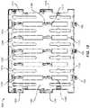
- FIGS. 15 and 16show a rear view and a perspective view of a rear 1500 of a multi-purpose storage-system partition 800 , respectively.
- rear 1500may include various storage-drive contact points for retaining carrierless storage drives within storage-system drawer 500 .
- storage-drive contact points 1502 - 1508may be adapted to contact and retain the front and back of one side of a storage drive.
- storage-drive contact points 1510 - 1516may be adapted to contact and retain the front and back of one side of another storage drive.
- storage-drive contact points 1502 - 1508may be spaced to easily accept a storage drive and/or prevent the storage drive from moving relative to multi-purpose storage-system partition 800 .
- Storage-drive contact points 1502 - 1508may also apply a clamping force to the storage-drive and/or may dampen the motion of the storage drive relative to multi-purpose storage-system partition 800 and storage-system drawer 500 .
- Storage-drive contact points 1502 - 1516may be made of any suitable material. In some examples, storage-drive contact points 1502 - 1516 may be made of suitable shock-absorbing material, such as a synthetic rubber.
- rear 1500 of multi-purpose storage-system partition 800may include various holes and/or openings.
- multi-purpose storage-system partition 800may include vents 1518 , 1520 , 1522 , and 1524 that enable air to pass through multi-purpose storage-system partition 800 , the storage drives retained by multi-purpose storage-system partition 800 , and storage-system drawer 500 .
- multi-purpose storage-system partition 800may include various features for helping a technician align storage drives with the contact points of multi-purpose storage-system partition 800 .
- multi-purpose storage-system partition 800may include alignment protrusions, such as protrusions 1526 and 1528 , located above each contact point of multi-purpose storage-system partition 800 .
- multi-purpose storage-system partition 800may also include screw holes, such as screw holes 1600 and 1602 , that accept screws that couple multi-purpose storage-system partition 800 to storage-system drawer 500 .
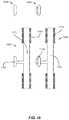
- FIGS. 17 and 18show a perspective view and a front view of storage-drive contact points 1502 - 1508 , respectively.
- storage-drive contact point 1506may include a nub 1700 with the same shape as storage-drive contact point 1502 and a planar portion 1702 with small protruding ridges (e.g., ridge 1708 )
- storage-drive contact point 1508may include a nub 1704 with the same shape as storage-drive contact point 1504 and a planar portion 1706 with small protruding ridges (e.g., ridge 1708 ).
- each of planar portions 1702 and 1704may be configured to apply a clamping force to the side of a storage-drive and/or dampen the motion of the storage drive relative to multi-purpose storage-system partition 800 and storage-system drawer 500 .
- FIG. 19shows a bottom view of a bottom 1900 of multi-purpose storage-system partition 800 .
- bottom 1900may include three keyhole fasteners 700 that may be configured to retain removable drive-plane board 100 within storage-system drawer 500 and a screw hole 1902 that accepts one of screws 702 in FIG. 7 that couples drive-plane board 100 to storage-system drawer 500 and aligns multi-purpose storage-system partition 800 to drive-plane board 100 to allow for proper alignment of storage drives 402 to storage-drive connectors 104 .
- FIG. 20shows an exploded view of multi-purpose storage-system partition 800 .
- multi-purpose storage-system partition 800may include a front portion 2002 , a rear portion 2004 , upper storage-drive contact points 2006 , lower storage-drive contact points 2008 , upper storage-drive contact points 2010 , lower storage-drive contact points 2012 , brace 1214 , screw-thread inserts 2016 , and light pipes 2018 .
- front portion 2002 , upper storage-drive contact points 2006 , and lower storage-drive contact points 2008may form a single injection-molded part.
- the injected-molded partmay be a double-shot injection-molded part that includes a substantially rigid plastic portion and a synthetic rubber portion.
- front portion 2002may form the substantially rigid plastic portion, and upper storage-drive contact points 2006 , and lower storage-drive contact points 2008 may form the synthetic rubber portion.
- Rear portion 2004 , upper storage-drive contact points 2010 , and lower storage-drive contact points 2012may similarly form a single injection-molded part.
- rear portion 2004may include protrusions, such as protrusion 2102 , around which upper storage-drive contact points 2010 may be formed and recesses, such as recess 2104 , within which lower storage-drive contact points 2012 may be formed.
- brace 1214may be constructed from metal and affixed to front portion 2002 to provide structural support for multi-purpose storage-system partition 800 .
- each of light pipes 2018may act as part of an indicator light (indicator 1004 in FIG. 10 ) that indicates the state of a storage drive.
- all or a portion of each light pipemay be formed from a transparent or translucent material to allow light from a light-emitting diode (LED) to pass through the light pipe.
- an LEDmay be positioned at a proximal end of each of light pipes 2018 .
- Multi-colored LEDsmay be used to cause the light pipe to glow different colors to indicate different states (e.g., green may indicate that a drive is fully operational, amber may indicate that a drive needs to be serviced, etc.).
- a close-up perspective view of a light pipe 2018is provided in FIG. 24 .
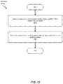
- FIG. 23shows, by way of example, a method for manufacturing portions of a multi-purpose storage-system partition via a double-shot injection-molding process.
- a first portion of a multi-purpose storage-system partitionmay be molded from a substantially rigid plastic.
- front portion 2002may be molded from a substantially rigid plastic.
- Rear portion 2004may likewise be molded from a substantially rigid plastic.
- a second portion of the multi-purpose storage-system partitionmay be molded from a synthetic rubber.
- upper storage-drive contact points 2006 and lower storage-drive contact points 2008may be molded around front portion 2002 from a synthetic rubber.
- upper storage-drive contact points 2010 and lower storage-drive contact points 2012may be molded around rear portion 2004 from synthetic rubber.
- the multi-purpose storage-system partitions disclosed hereinmay be used in a storage-system chassis to (1) secure carrierless storage drives within the storage-system chassis, (2) provide structural support for the storage-system chassis, and/or (3) provide attachment points for other removable storage-system components, such as a removable drive-plane board, within the storage-system chassis.
- the multi-purpose storage-system partitions disclosed hereinmay be lightweight double-shot injection-molded partitions that include rubber contact points that securely position carrierless storage drives within the storage-system chassis and provide shock and vibration dampening and isolation for the carrierless storage drives.
- the multi-purpose storage-system partitions disclosed hereinmay also include vertical openings that allow air to pass through the storage-system chassis and through the storage drives secured by the multi-purpose storage-system partitions.
Landscapes
- Engineering & Computer Science (AREA)
- Computer Hardware Design (AREA)
- General Engineering & Computer Science (AREA)
- Microelectronics & Electronic Packaging (AREA)
- Physics & Mathematics (AREA)
- Thermal Sciences (AREA)
- Drawers Of Furniture (AREA)
Abstract
Description
Claims (20)
Priority Applications (1)
| Application Number | Priority Date | Filing Date | Title |
|---|---|---|---|
| US15/708,069US10588238B2 (en) | 2017-09-18 | 2017-09-18 | Apparatus, system, and method for partitioning a storage-system chassis |
Applications Claiming Priority (1)
| Application Number | Priority Date | Filing Date | Title |
|---|---|---|---|
| US15/708,069US10588238B2 (en) | 2017-09-18 | 2017-09-18 | Apparatus, system, and method for partitioning a storage-system chassis |
Publications (2)
| Publication Number | Publication Date |
|---|---|
| US20190090374A1 US20190090374A1 (en) | 2019-03-21 |
| US10588238B2true US10588238B2 (en) | 2020-03-10 |
Family
ID=65720928
Family Applications (1)
| Application Number | Title | Priority Date | Filing Date |
|---|---|---|---|
| US15/708,069Expired - Fee RelatedUS10588238B2 (en) | 2017-09-18 | 2017-09-18 | Apparatus, system, and method for partitioning a storage-system chassis |
Country Status (1)
| Country | Link |
|---|---|
| US (1) | US10588238B2 (en) |
Cited By (2)
| Publication number | Priority date | Publication date | Assignee | Title |
|---|---|---|---|---|
| US10721833B1 (en)* | 2019-03-27 | 2020-07-21 | Hongfujin Precision Electronics (Tianjin) Co., Ltd. | Server |
| US11096308B2 (en)* | 2019-08-30 | 2021-08-17 | Inventec (Pudong) Technology Corporation | Processing assembly |
Families Citing this family (8)
| Publication number | Priority date | Publication date | Assignee | Title |
|---|---|---|---|---|
| US11039546B2 (en)* | 2015-12-25 | 2021-06-15 | Ting-Jui Wang | Pull-out aiding device and chassis-wall module with pull-out aiding function |
| US10687435B2 (en) | 2017-08-28 | 2020-06-16 | Facebook, Inc. | Apparatus, system, and method for enabling multiple storage-system configurations |
| US10736228B2 (en) | 2017-08-31 | 2020-08-04 | Facebook, Inc. | Removeable drive-plane apparatus, system, and method |
| US10537035B2 (en) | 2017-09-06 | 2020-01-14 | Facebook, Inc. | Apparatus, system, and method for securing hard drives in a storage chassis |
| US10558248B2 (en) | 2017-09-09 | 2020-02-11 | Facebook, Inc. | Apparatus, system, and method for indicating the status of and securing hard drives |
| US10757831B2 (en) | 2017-09-26 | 2020-08-25 | Facebook, Inc. | Apparatus, system, and method for reconfiguring air flow through a chassis |
| WO2020236166A1 (en)* | 2019-05-22 | 2020-11-26 | Hewlett-Packard Development Company, L.P. | Storage device carriers |
| TWI752754B (en)* | 2020-12-10 | 2022-01-11 | 好慶科技企業股份有限公司 | Package tray and computer case module including the package tray |
Citations (146)
| Publication number | Priority date | Publication date | Assignee | Title |
|---|---|---|---|---|
| US3601463A (en)* | 1970-05-22 | 1971-08-24 | Gen Motors Corp | Refrigerator cabinet encompassing a range of refrigerator volume |
| US3996500A (en) | 1975-06-16 | 1976-12-07 | Richco Plastic Company | Chassis connector and circuit board clip |
| USD294800S (en) | 1983-10-04 | 1988-03-22 | M.T.D. Medical Technology And Development Ltd. | Clip for supporting medical devices or the like on a support rail |
| US4969065A (en) | 1989-02-28 | 1990-11-06 | Petri Hector D | Spacer for circuit boards and circuit board assembly including same |
| US5262705A (en) | 1991-07-15 | 1993-11-16 | Nec Corporation | IC device for drive control of small hard disk drive unit |
| US5281149A (en) | 1992-07-06 | 1994-01-25 | Petri Hector D | Grounding circuit board standoff |
| US5724803A (en) | 1995-05-04 | 1998-03-10 | Hubbell Incorporated | Power supply chain with roller bar carrier |
| US5793614A (en) | 1996-09-03 | 1998-08-11 | Tektronix, Inc. | Injector/ejector for electronic module housing |
| US5957659A (en) | 1996-07-03 | 1999-09-28 | Matsushita Electric Industrial Co., Ltd. | Heat sink apparatus |
| US6021044A (en) | 1998-08-13 | 2000-02-01 | Data General Corporation | Heatsink assembly |
| US6109767A (en) | 1996-03-29 | 2000-08-29 | Minnesota Mining And Manufacturing Company | Honeycomb light and heat trap for projector |
| US6116375A (en) | 1995-11-16 | 2000-09-12 | Lorch; Frederick A. | Acoustic resonator |
| US6159031A (en) | 1999-06-07 | 2000-12-12 | Intel Corporation | Retention mechanism that can be used with different electronic assemblies |
| US6181549B1 (en) | 1997-06-24 | 2001-01-30 | Dell Products, L.P. | Chassis retaining system for an electronics rack |
| US6331915B1 (en) | 2000-06-13 | 2001-12-18 | Kenneth J. Myers | Lighting element including light emitting diodes, microprism sheet, reflector, and diffusing agent |
| US6385051B1 (en)* | 2000-03-13 | 2002-05-07 | Compaq Computer Corporation | Circuit board mounting apparatus and associated methods |
| US6404646B1 (en) | 2001-10-17 | 2002-06-11 | Enlight Corporation | PC board support adapted to support a PC board above a frame in a computer |
| US6469899B2 (en) | 2000-12-20 | 2002-10-22 | Compaq Information Technologies Group, L.P. | Modular rack-mount server arrangement |
| US6515854B1 (en) | 2000-07-31 | 2003-02-04 | Emc Corporation | Disk drive assembly with press fit lever |
| US6552915B2 (en) | 1999-05-31 | 2003-04-22 | Fujitsu Limited | Communications apparatus and plug-in unit |
| US20030123221A1 (en) | 2001-12-28 | 2003-07-03 | Yuan-Kun Liao | Computer with a removable add-on card fixing mechanism |
| US6621692B1 (en) | 2001-08-30 | 2003-09-16 | Emc Corporation | Computerized system having an interface apparatus with improved mounting features |
| US20030183448A1 (en) | 2002-03-29 | 2003-10-02 | Sleet Donovan Van | Acoustically insulated bezel |
| US20030200475A1 (en) | 2002-04-19 | 2003-10-23 | Eiji Komoto | Universal serial bus circuit and data structure |
| US20030200472A1 (en) | 2002-04-22 | 2003-10-23 | Kabushiki Kaisha Toshiba | Computer and power supply controlling method |
| US6695629B1 (en)* | 2002-10-25 | 2004-02-24 | Hewlett-Packard Development Company, L.P. | Low-profile mounting and connecting scheme for circuit boards |
| US6791843B1 (en) | 2003-06-11 | 2004-09-14 | Hewlett-Packard Development Company, L.P. | Parallel board connection system and method |
| US6798669B1 (en) | 2003-03-05 | 2004-09-28 | Inventec Corporation | Latching structure for motherboards |
| US6813165B2 (en) | 2002-11-18 | 2004-11-02 | Wistron Corporation | Board-locking fastener for fastening a motherboard on a housing of a computer |
| US20050057909A1 (en) | 2003-09-12 | 2005-03-17 | Mohamad El-Batal | Disk storage system with removable arrays of disk drives |
| US20050136747A1 (en)* | 2003-12-22 | 2005-06-23 | Panduit Corp. | Inductive and capacitive coupling balancing electrical connector |
| US20050182874A1 (en) | 2003-02-28 | 2005-08-18 | Herz John P. | Disk array controller and system with automated detection and control of both ATA and SCSI disk drives |
| US20050238421A1 (en) | 2004-04-21 | 2005-10-27 | Doerr Alan B | Latch assembly |
| US6995982B2 (en) | 2002-12-12 | 2006-02-07 | Dell Products L.P. | Spring loaded plunger for circuit board installation and removal |
| US7004764B2 (en) | 2004-06-25 | 2006-02-28 | Emc Corporation | Circuit board retainer |
| US20060075155A1 (en) | 2004-10-06 | 2006-04-06 | Dell Products L.P. | Information handling system including detection of serial attached small computer systems interface ("SAS") and serial advanced technology attachment ("SATA") devices |
| US20060134953A1 (en) | 2004-12-22 | 2006-06-22 | Adaptec, Inc. | Electronic module latching mechanism |
| US20060146507A1 (en)* | 2004-12-30 | 2006-07-06 | Tatung Co., Ltd. | Dual-usage fastener |
| US7084654B2 (en) | 2004-07-09 | 2006-08-01 | Sae Magnetics (H.K.) Ltd. | “2-step contact” clamping fixture for the flexible print circuit on a head gimbal assembly |
| US7088579B1 (en) | 2003-11-13 | 2006-08-08 | Storage Technology Corporation | Small form factor disk drive carrier |
| US20060274508A1 (en) | 2005-06-06 | 2006-12-07 | Stratus Technologies Bermuda Ltd. | Computer rack mounting system |
| US7167371B2 (en) | 2001-11-28 | 2007-01-23 | Hewlett-Packard Development Company, L.P. | Low profile latch activator |
| US20070195542A1 (en) | 2005-12-23 | 2007-08-23 | Ford Global Technologies, Llc | Illuminated door handle |
| US20070233781A1 (en) | 2006-03-31 | 2007-10-04 | Spectra Logic Corporation | High density array system having multiple storage units with active movable media drawers |
| US20070230111A1 (en) | 2006-03-31 | 2007-10-04 | Spectra Logic Corporation | High density array system with active movable media drawers |
| US20070234081A1 (en) | 2006-02-14 | 2007-10-04 | Fujitsu Limited | Disk enclosure |
| US7301778B1 (en) | 2006-05-04 | 2007-11-27 | Adlink Technology, Inc. | ATCA locking lever mounting structure |
| US7304855B1 (en) | 2003-03-03 | 2007-12-04 | Storage Technology Corporation | Canister-based storage system |
| US20080007913A1 (en) | 2006-07-06 | 2008-01-10 | Hybricon Corporation | Card Cage With Parallel Flow Paths Having Substantially Similar Lengths |
| US20080117569A1 (en) | 2006-11-20 | 2008-05-22 | Jia-Shunn Lee | Power-supplying device |
| US7411787B2 (en) | 2005-12-02 | 2008-08-12 | Hitachi, Ltd. | Storage control device |
| US20080195786A1 (en) | 2007-02-08 | 2008-08-14 | Inventec Corporation | Hard disk type detecting circuit and hard disk connecting port having the hard disk type detecting circuit |
| US7423354B2 (en) | 2003-12-25 | 2008-09-09 | Hitachi, Ltd. | Storage system |
| US20080264192A1 (en)* | 2007-04-30 | 2008-10-30 | Christensen Steven M | Printed Circuit Board Engagement Systems and Methods |
| US7505286B2 (en) | 2003-05-29 | 2009-03-17 | Sun Microsystems, Inc. | Printed circuit board assembly retention and support device |
| US7515413B1 (en) | 2007-04-27 | 2009-04-07 | Cisco Technology, Inc. | Fan field replaceable unit |
| US20090245745A1 (en) | 2008-03-28 | 2009-10-01 | Dennis Krampotich | Rear latch arrangement for sliding drawer |
| US20090271950A1 (en) | 2008-05-01 | 2009-11-05 | Fivetech Technology Inc. | Handle structure with locking unit |
| US20090274429A1 (en) | 2008-05-05 | 2009-11-05 | Dennis Krampotich | Front-access locking arrangement for sliding drawer |
| US20090310303A1 (en) | 2008-06-11 | 2009-12-17 | Advanced Digital Broadcast S.A. | Attachment assembly for mounting electronic devices |
| US7649750B2 (en) | 2007-05-30 | 2010-01-19 | T-Conn Precision Corporation | Latch for interface card |
| US20100195304A1 (en) | 2007-10-15 | 2010-08-05 | Fujitsu Limited | Printed circuit board unit and electronic apparatus |
| US20100296791A1 (en) | 2009-05-21 | 2010-11-25 | Elli Makrides-Saravanos | Fiber Optic Equipment Guides and Rails Configured with Stopping Position(s), and Related Equipment and Methods |
| US20110208937A1 (en) | 2009-04-21 | 2011-08-25 | Hitachi, Ltd. | Storage system, control methods for the same and programs |
| US8020902B1 (en) | 2006-01-13 | 2011-09-20 | Flextronics Ap, Llc | Integrated snap and handling feature |
| US20110273850A1 (en) | 2010-05-05 | 2011-11-10 | Inventec Corporation | Locking structure for draw-type electronic device |
| US20110299237A1 (en) | 2010-06-03 | 2011-12-08 | Wen-Peng Liang | Multi-level hard drive enclosure |
| US20110309730A1 (en) | 2010-06-22 | 2011-12-22 | Quality Craft Industries Inc. | Drawer latch |
| US20120004772A1 (en) | 2010-06-30 | 2012-01-05 | Carefusion 303, Inc. | Multi-lidded dispensing cartridge system |
| US20120020006A1 (en) | 2010-07-21 | 2012-01-26 | Inventec Corporation | Server |
| US8127059B1 (en) | 2005-09-02 | 2012-02-28 | Pmc-Sierra Us, Inc. | Apparatus for interconnecting hosts with storage devices |
| US20120134086A1 (en) | 2010-11-30 | 2012-05-31 | Inventec Corporation | Server |
| US8203851B2 (en) | 2009-02-09 | 2012-06-19 | Juniper Networks, Inc. | Retention-extraction device for removable cards in a chassis |
| US20120230815A1 (en) | 2011-03-08 | 2012-09-13 | Nidec Corporation | Ventilation fan |
| US20120257360A1 (en) | 2011-04-06 | 2012-10-11 | Hon Hai Precision Industry Co., Ltd. | Fixing apparatus for electronic device |
| US8310828B2 (en) | 2010-07-26 | 2012-11-13 | Xyratex Technology Limited | Storage enclosure and methods |
| US20120305745A1 (en) | 2011-05-31 | 2012-12-06 | Hon Hai Precision Industry Co., Ltd. | Fan mounting apparatus for an electronic device |
| US8331095B2 (en)* | 2010-02-09 | 2012-12-11 | Inventec Corporation | Storage |
| US20120320519A1 (en)* | 2011-06-20 | 2012-12-20 | Hon Hai Precision Industry Co., Ltd. | Storage device assembly |
| US8369080B2 (en) | 2011-02-25 | 2013-02-05 | Jui-Shu Huang | Removable hard disk drive bay |
| US20130050955A1 (en) | 2011-08-25 | 2013-02-28 | Lsi Corporation | Apparatus and systems having storage devices in a side accessible drive sled |
| US20130058054A1 (en) | 2011-09-07 | 2013-03-07 | Hon Hai Precision Industry Co., Ltd. | Fixing apparatus for expansion card |
| US8517054B2 (en) | 2010-01-18 | 2013-08-27 | Wistron Corporation | Flow resistance device |
| US20130258580A1 (en) | 2010-12-07 | 2013-10-03 | Fujitsu Limited | Storage apparatus and partition board used in storage apparatus |
| US8570720B2 (en) | 2011-05-03 | 2013-10-29 | Jeffrey Yao | CFAST duplication system |
| US20130325183A1 (en) | 2012-05-29 | 2013-12-05 | Carefusion 303, Inc. | Receptacle with dual-function actuator |
| US8636528B2 (en) | 2012-04-27 | 2014-01-28 | International Business Machines Corporation | Memory module connector with latch assist |
| US8657619B2 (en) | 2011-07-12 | 2014-02-25 | Wistron Corporation | Fixing mechanism for fixing a board and electronic device therewith |
| US20140111930A1 (en) | 2012-10-18 | 2014-04-24 | Dell Products L.P. | Adaptive information handling system rack rail mount |
| US20140118936A1 (en) | 2010-10-08 | 2014-05-01 | Etienne Merlet | Electronic module, guide rail of such a module and circuit board intended to be slotted into such a module |
| US8743549B2 (en)* | 2011-03-22 | 2014-06-03 | Amazon Technologies, Inc. | Modular mass storage system |
| US8749966B1 (en) | 2009-12-22 | 2014-06-10 | Emc Corporation | Data storage drive carrier |
| US20140187068A1 (en) | 2012-12-27 | 2014-07-03 | Cisco Technology, Inc. | High Insertion Force Ejector |
| US20140191636A1 (en) | 2013-01-10 | 2014-07-10 | Hon Hai Precision Industry Co., Ltd. | Electronic device enclosure with handle |
| US8848349B2 (en) | 2012-04-02 | 2014-09-30 | Wistron Corporation | Housing, a fastening member thereof and a display device incorporating the housing |
| US20140369002A1 (en) | 2013-06-18 | 2014-12-18 | Western Digital Technologies, Inc. | Fan plate |
| US8971052B2 (en) | 2012-04-03 | 2015-03-03 | Zhongshan Innocloud Intellectual Property Services Co., Ltd. | Fixing apparatus for expansion card |
| US20150156912A1 (en) | 2012-06-27 | 2015-06-04 | Huawei Technologies Co., Ltd. | Handle locking structure and electronic device having handle locking structure |
| US20150163946A1 (en) | 2012-11-07 | 2015-06-11 | Dell Products L.P. | Chassis drawer for modular information handling resources |
| US9066438B2 (en) | 2012-11-26 | 2015-06-23 | Wistron Corporation | Fixing mechanism for fixing an interface card of an electronic device and electronic device therewith |
| US9070419B1 (en) | 2014-12-04 | 2015-06-30 | Inventec (Pudong) Technology Corporation | Electronic apparatus with first and second sliding tray modules |
| US20150208548A1 (en) | 2014-01-22 | 2015-07-23 | Echostreams Innovative Solutions, Llc | Power supply having detachable fan |
| US9098233B2 (en) | 2013-01-23 | 2015-08-04 | Dot Hill Systems Corporation | Storage device carrier for high density storage system |
| US9101210B2 (en) | 2010-11-30 | 2015-08-11 | Wistron Corporation | Track type supporting mechanism and supporting system |
| US20150235673A1 (en) | 2012-07-11 | 2015-08-20 | Netgear, Inc. | Method and Apparatus for Providing Stackable Hard-Disk Drive Carrier Using Pull-Out Drawers |
| US9203188B1 (en) | 2013-11-06 | 2015-12-01 | Cisco Technology, Inc. | Single-motion trigger ejector with optical switch actuator |
| US20150380059A1 (en)* | 2014-06-26 | 2015-12-31 | HGST Netherlands B.V. | Hanging carrier for hdd |
| US20160018859A1 (en) | 2014-07-16 | 2016-01-21 | Wistron Corporation | Fixing mechanism and electronic device capable of assembling and disassembling an expansion card module |
| US20160042768A1 (en) | 2014-08-05 | 2016-02-11 | Quanta Computer Inc. | Horzontal coupling of vertically-oriented hard drive |
| US9274548B2 (en) | 2013-03-01 | 2016-03-01 | Seagate Technology Llc | Electronic apparatus comprising backplane and methods of assembling and disassembling |
| US9298230B2 (en)* | 2013-09-05 | 2016-03-29 | Hon Hai Precision Industry Co., Ltd. | Electronic device |
| US9313909B1 (en) | 2014-11-08 | 2016-04-12 | Jui-Shu Huang | Alignment device of a hard disk drive bay |
| US20160150667A1 (en) | 2014-11-26 | 2016-05-26 | Inventec (Pudong) Technology Corporation | Server |
| US20160150659A1 (en) | 2014-11-25 | 2016-05-26 | Super Micro Computer Inc. | Handle structure and server using the same |
| US9354003B2 (en) | 2014-04-10 | 2016-05-31 | Asia Vital Components Co., Ltd. | Heat sink fastening device and thermal module assembly using same |
| US9448601B1 (en)* | 2014-03-17 | 2016-09-20 | Amazon Technologies, Inc. | Modular mass storage system with controller |
| US9456519B2 (en) | 2013-12-23 | 2016-09-27 | Dell Products, L.P. | Single unit height storage sled with lateral storage device assembly supporting hot-removal of storage devices and slidable insertion and extraction from an information handling system rack |
| US9461389B2 (en) | 2012-08-27 | 2016-10-04 | Siemens Aktiengesellschaft | Securing and locking system for an electronic module |
| US20160330858A1 (en) | 2015-05-05 | 2016-11-10 | Facebook, Inc. | Component mounting assembly |
| US9538684B2 (en) | 2014-01-22 | 2017-01-03 | Quanta Computer, Inc. | Server device |
| US9545028B2 (en) | 2012-10-31 | 2017-01-10 | Fujitsu Limited | Electronic circuit unit and communication device |
| US9572276B2 (en) | 2014-11-06 | 2017-02-14 | Cinnos Technologies, Inc. | Smart mission critical rack |
| US9583877B1 (en) | 2015-04-10 | 2017-02-28 | Lockheed Martin Corporation | Insertion-extraction device for circuit card assemblies resident to the circuit receiving side |
| US9609778B1 (en) | 2015-10-05 | 2017-03-28 | Hewlett Packard Enterprise Development Lp | Server having a latch |
| US9763353B1 (en)* | 2015-03-23 | 2017-09-12 | Amazon Technologies, Inc. | Mass storage device retainer assembly |
| US9763350B2 (en) | 2013-01-23 | 2017-09-12 | Seagate Technology Llc | High density data storage system with improved storage device access |
| US9795052B2 (en) | 2015-09-10 | 2017-10-17 | Silverstone Technology Co., Ltd. | Handle structure and server using the same |
| US20170325361A1 (en)* | 2016-05-03 | 2017-11-09 | Quanta Computer Inc. | System with fresh air flow toward downstream components for cooling |
| US9936611B1 (en)* | 2014-03-17 | 2018-04-03 | Amazon Technologies, Inc. | Modular mass storage system |
| US9949407B1 (en) | 2015-05-29 | 2018-04-17 | Amazon Technologies, Inc. | Computer system with partial bypass cooling |
| US20180168071A1 (en) | 2015-06-23 | 2018-06-14 | Bripco Bvba | Data Centre Cooling System |
| US10058006B2 (en) | 2016-12-07 | 2018-08-21 | Dell Products L.P. | Lever release mechanism for information handling system chassis sled |
| US20180260349A1 (en) | 2017-03-13 | 2018-09-13 | American Megatrends, Inc. | System and method for detecting types of storage drives connected to backplane controller or enclosure management controller |
| US10165703B1 (en) | 2017-09-29 | 2018-12-25 | Facebook, Inc. | Data-center drawer and cable track assembly |
| US10178791B1 (en) | 2017-09-23 | 2019-01-08 | Facebook, Inc. | Apparatus, system, and method for securing computing components to printed circuit boards |
| US20190069440A1 (en)* | 2017-08-29 | 2019-02-28 | Facebook, Inc. | Apparatus, system, and method for directing air in a storage-system chassis |
| US20190069437A1 (en)* | 2017-08-28 | 2019-02-28 | Facebook, Inc. | Apparatus, system, and method for enabling multiple storage-system configurations |
| US20190069432A1 (en)* | 2017-08-31 | 2019-02-28 | Facebook, Inc. | Removeable drive-plane apparatus, system, and method |
| US20190073008A1 (en) | 2017-09-07 | 2019-03-07 | Facebook, Inc. | Apparatus, system, and method for detecting device types of storage devices |
| US20190075668A1 (en) | 2017-09-06 | 2019-03-07 | Facebook, Inc. | Apparatus, system, and method for securing hard drives in a storage chassis |
| US20190079565A1 (en) | 2017-09-09 | 2019-03-14 | Facebook, Inc. | Apparatus, system, and method for indicating the status of and securing hard drives |
| US20190090376A1 (en) | 2017-09-18 | 2019-03-21 | Facebook, Inc. | Apparatus, system, and method for resisting shock to a data-center rack |
| US10240615B1 (en) | 2017-09-23 | 2019-03-26 | Facebook, Inc. | Apparatus, system, and method for dampening vibrations generated by exhaust fans |
| US20190098795A1 (en) | 2017-09-26 | 2019-03-28 | Facebook, Inc. | Apparatus, system, and method for reconfiguring air flow through a chassis |
| US10264698B2 (en) | 2017-08-25 | 2019-04-16 | Facebook, Inc. | Systems and methods for mounting assembly pull-handles |
| US10372360B2 (en) | 2017-09-01 | 2019-08-06 | Facebook, Inc. | Apparatus, system, and method for reconfigurable media-agnostic storage |
- 2017
- 2017-09-18USUS15/708,069patent/US10588238B2/ennot_activeExpired - Fee Related
Patent Citations (149)
| Publication number | Priority date | Publication date | Assignee | Title |
|---|---|---|---|---|
| US3601463A (en)* | 1970-05-22 | 1971-08-24 | Gen Motors Corp | Refrigerator cabinet encompassing a range of refrigerator volume |
| US3996500A (en) | 1975-06-16 | 1976-12-07 | Richco Plastic Company | Chassis connector and circuit board clip |
| USD294800S (en) | 1983-10-04 | 1988-03-22 | M.T.D. Medical Technology And Development Ltd. | Clip for supporting medical devices or the like on a support rail |
| US4969065A (en) | 1989-02-28 | 1990-11-06 | Petri Hector D | Spacer for circuit boards and circuit board assembly including same |
| US5262705A (en) | 1991-07-15 | 1993-11-16 | Nec Corporation | IC device for drive control of small hard disk drive unit |
| US5281149A (en) | 1992-07-06 | 1994-01-25 | Petri Hector D | Grounding circuit board standoff |
| US5724803A (en) | 1995-05-04 | 1998-03-10 | Hubbell Incorporated | Power supply chain with roller bar carrier |
| US6116375A (en) | 1995-11-16 | 2000-09-12 | Lorch; Frederick A. | Acoustic resonator |
| US6109767A (en) | 1996-03-29 | 2000-08-29 | Minnesota Mining And Manufacturing Company | Honeycomb light and heat trap for projector |
| US5957659A (en) | 1996-07-03 | 1999-09-28 | Matsushita Electric Industrial Co., Ltd. | Heat sink apparatus |
| US5793614A (en) | 1996-09-03 | 1998-08-11 | Tektronix, Inc. | Injector/ejector for electronic module housing |
| US6181549B1 (en) | 1997-06-24 | 2001-01-30 | Dell Products, L.P. | Chassis retaining system for an electronics rack |
| US6021044A (en) | 1998-08-13 | 2000-02-01 | Data General Corporation | Heatsink assembly |
| US6552915B2 (en) | 1999-05-31 | 2003-04-22 | Fujitsu Limited | Communications apparatus and plug-in unit |
| US6159031A (en) | 1999-06-07 | 2000-12-12 | Intel Corporation | Retention mechanism that can be used with different electronic assemblies |
| US6385051B1 (en)* | 2000-03-13 | 2002-05-07 | Compaq Computer Corporation | Circuit board mounting apparatus and associated methods |
| US6331915B1 (en) | 2000-06-13 | 2001-12-18 | Kenneth J. Myers | Lighting element including light emitting diodes, microprism sheet, reflector, and diffusing agent |
| US6515854B1 (en) | 2000-07-31 | 2003-02-04 | Emc Corporation | Disk drive assembly with press fit lever |
| US6469899B2 (en) | 2000-12-20 | 2002-10-22 | Compaq Information Technologies Group, L.P. | Modular rack-mount server arrangement |
| US6621692B1 (en) | 2001-08-30 | 2003-09-16 | Emc Corporation | Computerized system having an interface apparatus with improved mounting features |
| US6404646B1 (en) | 2001-10-17 | 2002-06-11 | Enlight Corporation | PC board support adapted to support a PC board above a frame in a computer |
| US7167371B2 (en) | 2001-11-28 | 2007-01-23 | Hewlett-Packard Development Company, L.P. | Low profile latch activator |
| US20030123221A1 (en) | 2001-12-28 | 2003-07-03 | Yuan-Kun Liao | Computer with a removable add-on card fixing mechanism |
| US20030183448A1 (en) | 2002-03-29 | 2003-10-02 | Sleet Donovan Van | Acoustically insulated bezel |
| US20030200475A1 (en) | 2002-04-19 | 2003-10-23 | Eiji Komoto | Universal serial bus circuit and data structure |
| US20030200472A1 (en) | 2002-04-22 | 2003-10-23 | Kabushiki Kaisha Toshiba | Computer and power supply controlling method |
| US6695629B1 (en)* | 2002-10-25 | 2004-02-24 | Hewlett-Packard Development Company, L.P. | Low-profile mounting and connecting scheme for circuit boards |
| US6813165B2 (en) | 2002-11-18 | 2004-11-02 | Wistron Corporation | Board-locking fastener for fastening a motherboard on a housing of a computer |
| US6995982B2 (en) | 2002-12-12 | 2006-02-07 | Dell Products L.P. | Spring loaded plunger for circuit board installation and removal |
| US20050182874A1 (en) | 2003-02-28 | 2005-08-18 | Herz John P. | Disk array controller and system with automated detection and control of both ATA and SCSI disk drives |
| US7304855B1 (en) | 2003-03-03 | 2007-12-04 | Storage Technology Corporation | Canister-based storage system |
| US6798669B1 (en) | 2003-03-05 | 2004-09-28 | Inventec Corporation | Latching structure for motherboards |
| US7505286B2 (en) | 2003-05-29 | 2009-03-17 | Sun Microsystems, Inc. | Printed circuit board assembly retention and support device |
| US6791843B1 (en) | 2003-06-11 | 2004-09-14 | Hewlett-Packard Development Company, L.P. | Parallel board connection system and method |
| US6987674B2 (en) | 2003-09-12 | 2006-01-17 | Lsi Logic Corporation | Disk storage system with removable arrays of disk drives |
| US20050057909A1 (en) | 2003-09-12 | 2005-03-17 | Mohamad El-Batal | Disk storage system with removable arrays of disk drives |
| US7088579B1 (en) | 2003-11-13 | 2006-08-08 | Storage Technology Corporation | Small form factor disk drive carrier |
| US20050136747A1 (en)* | 2003-12-22 | 2005-06-23 | Panduit Corp. | Inductive and capacitive coupling balancing electrical connector |
| US7423354B2 (en) | 2003-12-25 | 2008-09-09 | Hitachi, Ltd. | Storage system |
| US20050238421A1 (en) | 2004-04-21 | 2005-10-27 | Doerr Alan B | Latch assembly |
| US7004764B2 (en) | 2004-06-25 | 2006-02-28 | Emc Corporation | Circuit board retainer |
| US7084654B2 (en) | 2004-07-09 | 2006-08-01 | Sae Magnetics (H.K.) Ltd. | “2-step contact” clamping fixture for the flexible print circuit on a head gimbal assembly |
| US20060075155A1 (en) | 2004-10-06 | 2006-04-06 | Dell Products L.P. | Information handling system including detection of serial attached small computer systems interface ("SAS") and serial advanced technology attachment ("SATA") devices |
| US20060134953A1 (en) | 2004-12-22 | 2006-06-22 | Adaptec, Inc. | Electronic module latching mechanism |
| US20060146507A1 (en)* | 2004-12-30 | 2006-07-06 | Tatung Co., Ltd. | Dual-usage fastener |
| US20060274508A1 (en) | 2005-06-06 | 2006-12-07 | Stratus Technologies Bermuda Ltd. | Computer rack mounting system |
| US8127059B1 (en) | 2005-09-02 | 2012-02-28 | Pmc-Sierra Us, Inc. | Apparatus for interconnecting hosts with storage devices |
| US7411787B2 (en) | 2005-12-02 | 2008-08-12 | Hitachi, Ltd. | Storage control device |
| US20070195542A1 (en) | 2005-12-23 | 2007-08-23 | Ford Global Technologies, Llc | Illuminated door handle |
| US8020902B1 (en) | 2006-01-13 | 2011-09-20 | Flextronics Ap, Llc | Integrated snap and handling feature |
| US20070234081A1 (en) | 2006-02-14 | 2007-10-04 | Fujitsu Limited | Disk enclosure |
| US20070230111A1 (en) | 2006-03-31 | 2007-10-04 | Spectra Logic Corporation | High density array system with active movable media drawers |
| US20070233781A1 (en) | 2006-03-31 | 2007-10-04 | Spectra Logic Corporation | High density array system having multiple storage units with active movable media drawers |
| US7301778B1 (en) | 2006-05-04 | 2007-11-27 | Adlink Technology, Inc. | ATCA locking lever mounting structure |
| US20080007913A1 (en) | 2006-07-06 | 2008-01-10 | Hybricon Corporation | Card Cage With Parallel Flow Paths Having Substantially Similar Lengths |
| US20080117569A1 (en) | 2006-11-20 | 2008-05-22 | Jia-Shunn Lee | Power-supplying device |
| US20080195786A1 (en) | 2007-02-08 | 2008-08-14 | Inventec Corporation | Hard disk type detecting circuit and hard disk connecting port having the hard disk type detecting circuit |
| US7515413B1 (en) | 2007-04-27 | 2009-04-07 | Cisco Technology, Inc. | Fan field replaceable unit |
| US20080264192A1 (en)* | 2007-04-30 | 2008-10-30 | Christensen Steven M | Printed Circuit Board Engagement Systems and Methods |
| US7649750B2 (en) | 2007-05-30 | 2010-01-19 | T-Conn Precision Corporation | Latch for interface card |
| US20100195304A1 (en) | 2007-10-15 | 2010-08-05 | Fujitsu Limited | Printed circuit board unit and electronic apparatus |
| US20090245745A1 (en) | 2008-03-28 | 2009-10-01 | Dennis Krampotich | Rear latch arrangement for sliding drawer |
| US20090271950A1 (en) | 2008-05-01 | 2009-11-05 | Fivetech Technology Inc. | Handle structure with locking unit |
| US20090274429A1 (en) | 2008-05-05 | 2009-11-05 | Dennis Krampotich | Front-access locking arrangement for sliding drawer |
| US20090310303A1 (en) | 2008-06-11 | 2009-12-17 | Advanced Digital Broadcast S.A. | Attachment assembly for mounting electronic devices |
| US8203851B2 (en) | 2009-02-09 | 2012-06-19 | Juniper Networks, Inc. | Retention-extraction device for removable cards in a chassis |
| US20110208937A1 (en) | 2009-04-21 | 2011-08-25 | Hitachi, Ltd. | Storage system, control methods for the same and programs |
| US20100296791A1 (en) | 2009-05-21 | 2010-11-25 | Elli Makrides-Saravanos | Fiber Optic Equipment Guides and Rails Configured with Stopping Position(s), and Related Equipment and Methods |
| US8749966B1 (en) | 2009-12-22 | 2014-06-10 | Emc Corporation | Data storage drive carrier |
| US8517054B2 (en) | 2010-01-18 | 2013-08-27 | Wistron Corporation | Flow resistance device |
| US8331095B2 (en)* | 2010-02-09 | 2012-12-11 | Inventec Corporation | Storage |
| US20110273850A1 (en) | 2010-05-05 | 2011-11-10 | Inventec Corporation | Locking structure for draw-type electronic device |
| US20110299237A1 (en) | 2010-06-03 | 2011-12-08 | Wen-Peng Liang | Multi-level hard drive enclosure |
| US20110309730A1 (en) | 2010-06-22 | 2011-12-22 | Quality Craft Industries Inc. | Drawer latch |
| US20120004772A1 (en) | 2010-06-30 | 2012-01-05 | Carefusion 303, Inc. | Multi-lidded dispensing cartridge system |
| US20120020006A1 (en) | 2010-07-21 | 2012-01-26 | Inventec Corporation | Server |
| US8310828B2 (en) | 2010-07-26 | 2012-11-13 | Xyratex Technology Limited | Storage enclosure and methods |
| US20140118936A1 (en) | 2010-10-08 | 2014-05-01 | Etienne Merlet | Electronic module, guide rail of such a module and circuit board intended to be slotted into such a module |
| US20120134086A1 (en) | 2010-11-30 | 2012-05-31 | Inventec Corporation | Server |
| US9101210B2 (en) | 2010-11-30 | 2015-08-11 | Wistron Corporation | Track type supporting mechanism and supporting system |
| US20130258580A1 (en) | 2010-12-07 | 2013-10-03 | Fujitsu Limited | Storage apparatus and partition board used in storage apparatus |
| US8369080B2 (en) | 2011-02-25 | 2013-02-05 | Jui-Shu Huang | Removable hard disk drive bay |
| US20120230815A1 (en) | 2011-03-08 | 2012-09-13 | Nidec Corporation | Ventilation fan |
| US8743549B2 (en)* | 2011-03-22 | 2014-06-03 | Amazon Technologies, Inc. | Modular mass storage system |
| US20120257360A1 (en) | 2011-04-06 | 2012-10-11 | Hon Hai Precision Industry Co., Ltd. | Fixing apparatus for electronic device |
| US8570720B2 (en) | 2011-05-03 | 2013-10-29 | Jeffrey Yao | CFAST duplication system |
| US20120305745A1 (en) | 2011-05-31 | 2012-12-06 | Hon Hai Precision Industry Co., Ltd. | Fan mounting apparatus for an electronic device |
| US20120320519A1 (en)* | 2011-06-20 | 2012-12-20 | Hon Hai Precision Industry Co., Ltd. | Storage device assembly |
| US8657619B2 (en) | 2011-07-12 | 2014-02-25 | Wistron Corporation | Fixing mechanism for fixing a board and electronic device therewith |
| US20130050955A1 (en) | 2011-08-25 | 2013-02-28 | Lsi Corporation | Apparatus and systems having storage devices in a side accessible drive sled |
| US20130058054A1 (en) | 2011-09-07 | 2013-03-07 | Hon Hai Precision Industry Co., Ltd. | Fixing apparatus for expansion card |
| US8848349B2 (en) | 2012-04-02 | 2014-09-30 | Wistron Corporation | Housing, a fastening member thereof and a display device incorporating the housing |
| US8971052B2 (en) | 2012-04-03 | 2015-03-03 | Zhongshan Innocloud Intellectual Property Services Co., Ltd. | Fixing apparatus for expansion card |
| US8636528B2 (en) | 2012-04-27 | 2014-01-28 | International Business Machines Corporation | Memory module connector with latch assist |
| US20130325183A1 (en) | 2012-05-29 | 2013-12-05 | Carefusion 303, Inc. | Receptacle with dual-function actuator |
| US20150156912A1 (en) | 2012-06-27 | 2015-06-04 | Huawei Technologies Co., Ltd. | Handle locking structure and electronic device having handle locking structure |
| US20150235673A1 (en) | 2012-07-11 | 2015-08-20 | Netgear, Inc. | Method and Apparatus for Providing Stackable Hard-Disk Drive Carrier Using Pull-Out Drawers |
| US9461389B2 (en) | 2012-08-27 | 2016-10-04 | Siemens Aktiengesellschaft | Securing and locking system for an electronic module |
| US20140111930A1 (en) | 2012-10-18 | 2014-04-24 | Dell Products L.P. | Adaptive information handling system rack rail mount |
| US9545028B2 (en) | 2012-10-31 | 2017-01-10 | Fujitsu Limited | Electronic circuit unit and communication device |
| US20150163946A1 (en) | 2012-11-07 | 2015-06-11 | Dell Products L.P. | Chassis drawer for modular information handling resources |
| US9066438B2 (en) | 2012-11-26 | 2015-06-23 | Wistron Corporation | Fixing mechanism for fixing an interface card of an electronic device and electronic device therewith |
| US20140187068A1 (en) | 2012-12-27 | 2014-07-03 | Cisco Technology, Inc. | High Insertion Force Ejector |
| US8944538B2 (en) | 2013-01-10 | 2015-02-03 | Hong Fu Jin Precision Industry (Shenzhen) Co., Ltd. | Electronic device enclosure with handle |
| US20140191636A1 (en) | 2013-01-10 | 2014-07-10 | Hon Hai Precision Industry Co., Ltd. | Electronic device enclosure with handle |
| US9098233B2 (en) | 2013-01-23 | 2015-08-04 | Dot Hill Systems Corporation | Storage device carrier for high density storage system |
| US9763350B2 (en) | 2013-01-23 | 2017-09-12 | Seagate Technology Llc | High density data storage system with improved storage device access |
| US9274548B2 (en) | 2013-03-01 | 2016-03-01 | Seagate Technology Llc | Electronic apparatus comprising backplane and methods of assembling and disassembling |
| US20140369002A1 (en) | 2013-06-18 | 2014-12-18 | Western Digital Technologies, Inc. | Fan plate |
| US9298230B2 (en)* | 2013-09-05 | 2016-03-29 | Hon Hai Precision Industry Co., Ltd. | Electronic device |
| US9203188B1 (en) | 2013-11-06 | 2015-12-01 | Cisco Technology, Inc. | Single-motion trigger ejector with optical switch actuator |
| US9456519B2 (en) | 2013-12-23 | 2016-09-27 | Dell Products, L.P. | Single unit height storage sled with lateral storage device assembly supporting hot-removal of storage devices and slidable insertion and extraction from an information handling system rack |
| US20150208548A1 (en) | 2014-01-22 | 2015-07-23 | Echostreams Innovative Solutions, Llc | Power supply having detachable fan |
| US9538684B2 (en) | 2014-01-22 | 2017-01-03 | Quanta Computer, Inc. | Server device |
| US9448601B1 (en)* | 2014-03-17 | 2016-09-20 | Amazon Technologies, Inc. | Modular mass storage system with controller |
| US9936611B1 (en)* | 2014-03-17 | 2018-04-03 | Amazon Technologies, Inc. | Modular mass storage system |
| US9354003B2 (en) | 2014-04-10 | 2016-05-31 | Asia Vital Components Co., Ltd. | Heat sink fastening device and thermal module assembly using same |
| US20150380059A1 (en)* | 2014-06-26 | 2015-12-31 | HGST Netherlands B.V. | Hanging carrier for hdd |
| US20160018859A1 (en) | 2014-07-16 | 2016-01-21 | Wistron Corporation | Fixing mechanism and electronic device capable of assembling and disassembling an expansion card module |
| US9454190B2 (en) | 2014-07-16 | 2016-09-27 | Wistron Corporation | Fixing mechanism and electronic device capable of assembling and disassembling an expansion card module |
| US20160042768A1 (en) | 2014-08-05 | 2016-02-11 | Quanta Computer Inc. | Horzontal coupling of vertically-oriented hard drive |
| US9572276B2 (en) | 2014-11-06 | 2017-02-14 | Cinnos Technologies, Inc. | Smart mission critical rack |
| US9313909B1 (en) | 2014-11-08 | 2016-04-12 | Jui-Shu Huang | Alignment device of a hard disk drive bay |
| US20160150659A1 (en) | 2014-11-25 | 2016-05-26 | Super Micro Computer Inc. | Handle structure and server using the same |
| US20160150667A1 (en) | 2014-11-26 | 2016-05-26 | Inventec (Pudong) Technology Corporation | Server |
| US9070419B1 (en) | 2014-12-04 | 2015-06-30 | Inventec (Pudong) Technology Corporation | Electronic apparatus with first and second sliding tray modules |
| US9763353B1 (en)* | 2015-03-23 | 2017-09-12 | Amazon Technologies, Inc. | Mass storage device retainer assembly |
| US9583877B1 (en) | 2015-04-10 | 2017-02-28 | Lockheed Martin Corporation | Insertion-extraction device for circuit card assemblies resident to the circuit receiving side |
| US20160330858A1 (en) | 2015-05-05 | 2016-11-10 | Facebook, Inc. | Component mounting assembly |
| US9949407B1 (en) | 2015-05-29 | 2018-04-17 | Amazon Technologies, Inc. | Computer system with partial bypass cooling |
| US20180168071A1 (en) | 2015-06-23 | 2018-06-14 | Bripco Bvba | Data Centre Cooling System |
| US9795052B2 (en) | 2015-09-10 | 2017-10-17 | Silverstone Technology Co., Ltd. | Handle structure and server using the same |
| US9609778B1 (en) | 2015-10-05 | 2017-03-28 | Hewlett Packard Enterprise Development Lp | Server having a latch |
| US20170325361A1 (en)* | 2016-05-03 | 2017-11-09 | Quanta Computer Inc. | System with fresh air flow toward downstream components for cooling |
| US10058006B2 (en) | 2016-12-07 | 2018-08-21 | Dell Products L.P. | Lever release mechanism for information handling system chassis sled |
| US20180260349A1 (en) | 2017-03-13 | 2018-09-13 | American Megatrends, Inc. | System and method for detecting types of storage drives connected to backplane controller or enclosure management controller |
| US10264698B2 (en) | 2017-08-25 | 2019-04-16 | Facebook, Inc. | Systems and methods for mounting assembly pull-handles |
| US20190069437A1 (en)* | 2017-08-28 | 2019-02-28 | Facebook, Inc. | Apparatus, system, and method for enabling multiple storage-system configurations |
| US20190069440A1 (en)* | 2017-08-29 | 2019-02-28 | Facebook, Inc. | Apparatus, system, and method for directing air in a storage-system chassis |
| US20190069432A1 (en)* | 2017-08-31 | 2019-02-28 | Facebook, Inc. | Removeable drive-plane apparatus, system, and method |
| US10372360B2 (en) | 2017-09-01 | 2019-08-06 | Facebook, Inc. | Apparatus, system, and method for reconfigurable media-agnostic storage |
| US20190075668A1 (en) | 2017-09-06 | 2019-03-07 | Facebook, Inc. | Apparatus, system, and method for securing hard drives in a storage chassis |
| US20190073008A1 (en) | 2017-09-07 | 2019-03-07 | Facebook, Inc. | Apparatus, system, and method for detecting device types of storage devices |
| US20190079565A1 (en) | 2017-09-09 | 2019-03-14 | Facebook, Inc. | Apparatus, system, and method for indicating the status of and securing hard drives |
| US20190090376A1 (en) | 2017-09-18 | 2019-03-21 | Facebook, Inc. | Apparatus, system, and method for resisting shock to a data-center rack |
| US10240615B1 (en) | 2017-09-23 | 2019-03-26 | Facebook, Inc. | Apparatus, system, and method for dampening vibrations generated by exhaust fans |
| US10178791B1 (en) | 2017-09-23 | 2019-01-08 | Facebook, Inc. | Apparatus, system, and method for securing computing components to printed circuit boards |
| US20190098795A1 (en) | 2017-09-26 | 2019-03-28 | Facebook, Inc. | Apparatus, system, and method for reconfiguring air flow through a chassis |
| US10165703B1 (en) | 2017-09-29 | 2018-12-25 | Facebook, Inc. | Data-center drawer and cable track assembly |
Non-Patent Citations (20)
| Title |
|---|
| Acoustic Attenuation; https://en.wikipedia.org/wiki/Acoustic_attenuation; Oct. 22, 2012. |
| Bisson; How Facebook Does Storage; https://thenewstack.io/facebook-storage. |
| Chuankeat Kho et al.; Apparatus, System, and Method for Dampening Vibrations Generated by Exhaust Fans; U.S. Appl. No. 15/713,609, filed Sep. 23, 2017. |
| Chuankeat Kho et al.; Apparatus, System, and Method for Resisting Shock to a Data-Center Rack; U.S. Appl. No. 15/708,075, filed Sep. 18, 2017. |
| Chuankeat Kho et al.; Removeable Drive-Plane Apparatus, System, and Method; U.S. Appl. No. 15/693,362, filed Aug. 31, 2017. |
| Chuankeat Kho et al.; Systems and Methods for Mounting Assembly Pull-Handles; U.S. Appl. No. 15/687,406, filed Aug. 25, 2017. |
| Chuankeat Kho; Apparatus, System, and Method for Securing Computing Components to Printed Circuit Boards; U.S. Appl. No. 15/713,607, filed Sep. 23, 2017. |
| Electromagnetic Shielding; https://en.wikipedia.org/wiki/Electromagnetic_shielding; May 15, 2016. |
| Jason Adrian et al.; Bryce Canyon Storage Specification; Jan. 31, 2017. |
| Jason Adrian; Introducing Bryce Canyon: Our next-generation storage platform; https://code.facebook.com/posts/1869788206569924/introducing-bryce-canyon-our-next-generation-storage-platform/; Mar. 8, 2017. |
| Jason David Adrian et al.; Apparatus, System, and Method for Enabling Multiple Storage-System Configurations; U.S. Appl. No. 15/688,830, filed Aug. 28, 2017. |
| Jason David Adrian et al.; Apparatus, System, and Method for Reconfigurable Media-Agnostic Storage ; U.S. Appl. No. 15/694,068, filed Sep. 1, 2017. |
| Jason David Adrian et al.; Apparatus, System, and Method for Securing Hard Drives in a Storage Chassis; U.S. Appl. No. 15/697,405, filed Sep. 6, 2017. |
| Jason David Adrian; An Apparatus, System, and Method for Reconfiguring Air Flow Through a Chassis; U.S. Appl. No. 15/716,251, filed Sep. 26, 2017. |
| Jason David Adrian; Apparatus, System, and Method for Detecting Device Types of Storage Devices; U.S. Appl. No. 15/698,540, filed Sep. 7, 2017. |
| Jason David Adrian; Apparatus, System, and Method for Directing Air in a Storage-System Chassis; U.S. Appl. No. 15/689,650, filed Aug. 29, 2017. |
| Jason David Adrian; Apparatus, System, and Method for Indicating the Status of and Securing Hard Drives; U.S. Appl. No. 15/700,112, filed Sep. 9, 2017. |
| Jason David Adrian; Data-Center Drawer and Cable Track Assembly; U.S. Appl. No. 15/720,647, filed Sep. 29, 2017. |
| Open Compute Project; http://opencompute.org/; as accessed Sep. 29, 2017. |
| What's the Difference Between SATA and SAS Hard Drives?; https://www.pickaweb.co.uk/kb/difference-between-sata-sas-hard-drives/. |
Cited By (2)
| Publication number | Priority date | Publication date | Assignee | Title |
|---|---|---|---|---|
| US10721833B1 (en)* | 2019-03-27 | 2020-07-21 | Hongfujin Precision Electronics (Tianjin) Co., Ltd. | Server |
| US11096308B2 (en)* | 2019-08-30 | 2021-08-17 | Inventec (Pudong) Technology Corporation | Processing assembly |
Also Published As
| Publication number | Publication date |
|---|---|
| US20190090374A1 (en) | 2019-03-21 |
Similar Documents
| Publication | Publication Date | Title |
|---|---|---|
| US10588238B2 (en) | Apparatus, system, and method for partitioning a storage-system chassis | |
| US11032934B1 (en) | Apparatus, system, and method for enabling multiple storage-system configurations | |
| US10736228B2 (en) | Removeable drive-plane apparatus, system, and method | |
| US10349554B2 (en) | Apparatus, system, and method for directing air in a storage-system chassis | |
| US10001819B2 (en) | Dual-sided rackmount modular data processing assembly | |
| US10206297B2 (en) | Meshed architecture rackmount storage assembly | |
| US9865980B2 (en) | Multi-node server platform | |
| EP2248230B1 (en) | Modular system and retractable assembly for electronic devices | |
| US5227957A (en) | Modular computer system with passive backplane | |
| US7362566B1 (en) | External removable hard disk drive system | |
| US8508929B2 (en) | Implementing enhanced cover-mounted, auto-docking for multiple DASD configurations | |
| US10372360B2 (en) | Apparatus, system, and method for reconfigurable media-agnostic storage | |
| US10810152B2 (en) | Storage device carrier assembly | |
| US10178807B2 (en) | Top loading cartridge | |
| US9807901B2 (en) | Multiple graphics processing unit platform | |
| US20160073554A1 (en) | Structural subassembly for use in an information handling system chassis | |
| US10025357B2 (en) | Enclosure system for computing equipment | |
| US9807902B2 (en) | Top loading cartridge | |
| CN108241412A (en) | Server rack | |
| US20160057887A1 (en) | Top loading cartridge | |
| CN108241413A (en) | Server rack | |
| US20140273556A1 (en) | High-density multidirectional midplane | |
| US7675744B2 (en) | Air distribution system compatible with disparate data storage systems | |
| US10928601B2 (en) | Network topology modules | |
| CN108241414B (en) | Server rack |
Legal Events
| Date | Code | Title | Description |
|---|---|---|---|
| FEPP | Fee payment procedure | Free format text:ENTITY STATUS SET TO UNDISCOUNTED (ORIGINAL EVENT CODE: BIG.); ENTITY STATUS OF PATENT OWNER: LARGE ENTITY | |
| AS | Assignment | Owner name:FACEBOOK, INC., CALIFORNIA Free format text:ASSIGNMENT OF ASSIGNORS INTEREST;ASSIGNORS:KHO , CHUANKEAT;ADRIAN, JASON DAVID;REEL/FRAME:043630/0926 Effective date:20170919 | |
| STPP | Information on status: patent application and granting procedure in general | Free format text:NON FINAL ACTION MAILED | |
| STPP | Information on status: patent application and granting procedure in general | Free format text:RESPONSE TO NON-FINAL OFFICE ACTION ENTERED AND FORWARDED TO EXAMINER | |
| STPP | Information on status: patent application and granting procedure in general | Free format text:NOTICE OF ALLOWANCE MAILED -- APPLICATION RECEIVED IN OFFICE OF PUBLICATIONS | |
| ZAAA | Notice of allowance and fees due | Free format text:ORIGINAL CODE: NOA | |
| ZAAB | Notice of allowance mailed | Free format text:ORIGINAL CODE: MN/=. | |
| STPP | Information on status: patent application and granting procedure in general | Free format text:PUBLICATIONS -- ISSUE FEE PAYMENT VERIFIED | |
| STCF | Information on status: patent grant | Free format text:PATENTED CASE | |
| AS | Assignment | Owner name:META PLATFORMS, INC., CALIFORNIA Free format text:CHANGE OF NAME;ASSIGNOR:FACEBOOK, INC.;REEL/FRAME:058871/0336 Effective date:20211028 | |
| FEPP | Fee payment procedure | Free format text:MAINTENANCE FEE REMINDER MAILED (ORIGINAL EVENT CODE: REM.); ENTITY STATUS OF PATENT OWNER: LARGE ENTITY | |
| LAPS | Lapse for failure to pay maintenance fees | Free format text:PATENT EXPIRED FOR FAILURE TO PAY MAINTENANCE FEES (ORIGINAL EVENT CODE: EXP.); ENTITY STATUS OF PATENT OWNER: LARGE ENTITY | |
| STCH | Information on status: patent discontinuation | Free format text:PATENT EXPIRED DUE TO NONPAYMENT OF MAINTENANCE FEES UNDER 37 CFR 1.362 | |
| FP | Lapsed due to failure to pay maintenance fee | Effective date:20240310 |