US10585442B2 - Securing product storage tanks against unauthorized delivery - Google Patents
Securing product storage tanks against unauthorized deliveryDownload PDFInfo
- Publication number
- US10585442B2 US10585442B2US15/966,200US201815966200AUS10585442B2US 10585442 B2US10585442 B2US 10585442B2US 201815966200 AUS201815966200 AUS 201815966200AUS 10585442 B2US10585442 B2US 10585442B2
- Authority
- US
- United States
- Prior art keywords
- delivery
- product type
- rcv
- storage tank
- control circuitry
- Prior art date
- Legal status (The legal status is an assumption and is not a legal conclusion. Google has not performed a legal analysis and makes no representation as to the accuracy of the status listed.)
- Active, expires
Links
Images


Classifications
- G—PHYSICS
- G05—CONTROLLING; REGULATING
- G05D—SYSTEMS FOR CONTROLLING OR REGULATING NON-ELECTRIC VARIABLES
- G05D7/00—Control of flow
- G05D7/06—Control of flow characterised by the use of electric means
- G05D7/0617—Control of flow characterised by the use of electric means specially adapted for fluid materials
- G05D7/0629—Control of flow characterised by the use of electric means specially adapted for fluid materials characterised by the type of regulator means
- G05D7/0676—Control of flow characterised by the use of electric means specially adapted for fluid materials characterised by the type of regulator means by action on flow sources
- B—PERFORMING OPERATIONS; TRANSPORTING
- B67—OPENING, CLOSING OR CLEANING BOTTLES, JARS OR SIMILAR CONTAINERS; LIQUID HANDLING
- B67D—DISPENSING, DELIVERING OR TRANSFERRING LIQUIDS, NOT OTHERWISE PROVIDED FOR
- B67D7/00—Apparatus or devices for transferring liquids from bulk storage containers or reservoirs into vehicles or into portable containers, e.g. for retail sale purposes
- B67D7/06—Details or accessories
- B67D7/32—Arrangements of safety or warning devices; Means for preventing unauthorised delivery of liquid
- B67D7/34—Means for preventing unauthorised delivery of liquid
- B67D7/344—Means for preventing unauthorised delivery of liquid by checking a correct coupling or coded information
- B67D7/346—Means for preventing unauthorised delivery of liquid by checking a correct coupling or coded information by reading a code
- B—PERFORMING OPERATIONS; TRANSPORTING
- B67—OPENING, CLOSING OR CLEANING BOTTLES, JARS OR SIMILAR CONTAINERS; LIQUID HANDLING
- B67D—DISPENSING, DELIVERING OR TRANSFERRING LIQUIDS, NOT OTHERWISE PROVIDED FOR
- B67D7/00—Apparatus or devices for transferring liquids from bulk storage containers or reservoirs into vehicles or into portable containers, e.g. for retail sale purposes
- B67D7/06—Details or accessories
- B67D7/32—Arrangements of safety or warning devices; Means for preventing unauthorised delivery of liquid
- B67D7/34—Means for preventing unauthorised delivery of liquid
- B67D7/344—Means for preventing unauthorised delivery of liquid by checking a correct coupling or coded information
- B67D7/348—Means for preventing unauthorised delivery of liquid by checking a correct coupling or coded information by interrogating an information transmitter, e.g. a transponder
- B—PERFORMING OPERATIONS; TRANSPORTING
- B67—OPENING, CLOSING OR CLEANING BOTTLES, JARS OR SIMILAR CONTAINERS; LIQUID HANDLING
- B67D—DISPENSING, DELIVERING OR TRANSFERRING LIQUIDS, NOT OTHERWISE PROVIDED FOR
- B67D7/00—Apparatus or devices for transferring liquids from bulk storage containers or reservoirs into vehicles or into portable containers, e.g. for retail sale purposes
- B67D7/06—Details or accessories
- B67D7/36—Arrangements of flow- or pressure-control valves
- G—PHYSICS
- G05—CONTROLLING; REGULATING
- G05B—CONTROL OR REGULATING SYSTEMS IN GENERAL; FUNCTIONAL ELEMENTS OF SUCH SYSTEMS; MONITORING OR TESTING ARRANGEMENTS FOR SUCH SYSTEMS OR ELEMENTS
- G05B19/00—Programme-control systems
- G05B19/02—Programme-control systems electric
- G05B19/04—Programme control other than numerical control, i.e. in sequence controllers or logic controllers
- G05B19/042—Programme control other than numerical control, i.e. in sequence controllers or logic controllers using digital processors
- G—PHYSICS
- G05—CONTROLLING; REGULATING
- G05B—CONTROL OR REGULATING SYSTEMS IN GENERAL; FUNCTIONAL ELEMENTS OF SUCH SYSTEMS; MONITORING OR TESTING ARRANGEMENTS FOR SUCH SYSTEMS OR ELEMENTS
- G05B19/00—Programme-control systems
- G05B19/02—Programme-control systems electric
- G05B19/18—Numerical control [NC], i.e. automatically operating machines, in particular machine tools, e.g. in a manufacturing environment, so as to execute positioning, movement or co-ordinated operations by means of programme data in numerical form
- G—PHYSICS
- G06—COMPUTING OR CALCULATING; COUNTING
- G06Q—INFORMATION AND COMMUNICATION TECHNOLOGY [ICT] SPECIALLY ADAPTED FOR ADMINISTRATIVE, COMMERCIAL, FINANCIAL, MANAGERIAL OR SUPERVISORY PURPOSES; SYSTEMS OR METHODS SPECIALLY ADAPTED FOR ADMINISTRATIVE, COMMERCIAL, FINANCIAL, MANAGERIAL OR SUPERVISORY PURPOSES, NOT OTHERWISE PROVIDED FOR
- G06Q10/00—Administration; Management
- G06Q10/08—Logistics, e.g. warehousing, loading or distribution; Inventory or stock management
- G06Q10/083—Shipping
- G06Q10/0832—Special goods or special handling procedures, e.g. handling of hazardous or fragile goods
- B—PERFORMING OPERATIONS; TRANSPORTING
- B67—OPENING, CLOSING OR CLEANING BOTTLES, JARS OR SIMILAR CONTAINERS; LIQUID HANDLING
- B67D—DISPENSING, DELIVERING OR TRANSFERRING LIQUIDS, NOT OTHERWISE PROVIDED FOR
- B67D7/00—Apparatus or devices for transferring liquids from bulk storage containers or reservoirs into vehicles or into portable containers, e.g. for retail sale purposes
- B67D7/04—Apparatus or devices for transferring liquids from bulk storage containers or reservoirs into vehicles or into portable containers, e.g. for retail sale purposes for transferring fuels, lubricants or mixed fuels and lubricants
- G—PHYSICS
- G05—CONTROLLING; REGULATING
- G05B—CONTROL OR REGULATING SYSTEMS IN GENERAL; FUNCTIONAL ELEMENTS OF SUCH SYSTEMS; MONITORING OR TESTING ARRANGEMENTS FOR SUCH SYSTEMS OR ELEMENTS
- G05B2219/00—Program-control systems
- G05B2219/10—Plc systems
- G05B2219/15—Plc structure of the system
- G05B2219/15117—Radio link, wireless
- G—PHYSICS
- G05—CONTROLLING; REGULATING
- G05B—CONTROL OR REGULATING SYSTEMS IN GENERAL; FUNCTIONAL ELEMENTS OF SUCH SYSTEMS; MONITORING OR TESTING ARRANGEMENTS FOR SUCH SYSTEMS OR ELEMENTS
- G05B2219/00—Program-control systems
- G05B2219/30—Nc systems
- G05B2219/36—Nc in input of data, input key till input tape
- G05B2219/36536—Inhibit, forbid, prevent execution of program if no tool or worpiece data
Definitions
- the inventionrelates to product delivery control and, more particularly, to securing product storage tanks against unauthorized delivery.
- Retail facilities selling liquid products stored in liquid storage tanksare located throughout the world.
- liquid storage tankse.g., gas stations
- productsare stored in bulk storage tanks, which are typically located underground.
- Each tankstores a unique petroleum product (e.g., gasoline, diesel, kerosene, etc.) to be dispensed through pump-dispensers at various retail facilities.
- the delivery of petroleum products (hereinafter, fuel) to retail facilitiesis conducted by a gravity drop from a compartment in a tanker truck. These tanker trucks are themselves loaded for delivery from larger tank systems located at wholesale distribution centers.
- Preventing unauthorized fuel deliveryis desirable for automotive fuel brands to maintain their brand products' exclusivity in the franchise retail gas stations, for fuel distributors in order to fulfill their exclusive relationships with retail gas stations, and to prevent contamination or improper mixing of fuel products.
- a business goal of fuel distributorsis to minimize unauthorized deliveries while maximizing the efficiency of authorized delivery operations. Unauthorized deliveries may take place at a time of fuel price fluctuations. When prices go down, the owner of a retail gas station might be tempted to purchase fuel from a freelance distributer at a lower price, breaching the long-term supply contract with a distributor.
- distributorstypically keep close track of their customers' inventory, but in practice, even with well monitored retail gas stations, distributors report that unauthorized deliveries cause them a loss of 2-20% of their total business. That is a loss of between 1.75 million and 17.5 million PER DAY for authorized distributors in the United States during the first six months of 2011 (calculation based on data from the Prime Supplier Report and the U.S. Energy Information Administration, which report that in the first half of 2011, total gasoline sales and deliveries was approximately 350 million gallons per day with an average distributor's margin of 50.25 per gallon).
- Remote controlled valveshave been previously used in other industries (e.g., water irrigation system), but have not been suitable for fuel or other industrial liquid products because (a) they do not support bulk liquid drops at very low hydrostatic pressure, (b) they are not effective for bidirectional flow, (c) they are hard to use in a flammable explosive environment, (d) they are not suited for battery operation due to energy consumption, and (e) they are typically unreliable, expensive, and difficult to use.
- the RCVs used hereinare suitable for allowing rapid bulk-liquid drops at any hydrostatic pressure, supporting bi-directional liquid flow and handling flammable liquids securely, including supporting ongoing maintenance, inspection and auditing activities without compromising on safety or security.
- the described embodimentsovercome the shortcomings of existing delivery systems by (a) providing automatic, real-time prevention of unauthorized deliveries, (b) eliminating post factum investigations, (c) minimizing the size of the professional control team, and (d) ensuring the quality of the delivered product by preventing contamination.
- the described embodimentsare independent of the delivered product type and are applicable for any industrial product (liquid or otherwise flowable, e.g., granular) for which unauthorized delivery or contamination by improper mixing of product types can occur.
- industrial productliquid or otherwise flowable, e.g., granular
- Detailed Descriptionis provided in terms of fuel distribution, which is a highly applicable market for the described embodiments.
- the challenges faced by distributors in the fuel marketare also the same as in other markets, e.g., milk, juice or hazardous agricultural liquids such as fertilizers and pesticides.
- a method of preventing contamination by a tanker truck in a bulk liquid storage tankmay include the steps of (a) providing an identification transmitter at an entry port of the bulk liquid storage tank, the identification transmitter storing an indication of a storage product type in the bulk storage tank; (b) communicating a delivery product type in the tanker truck to control circuitry in the tanker truck; (c) the identification transmitter communicating the storage product type to the control circuitry; and (d) the control circuitry comparing the delivery product type with the storage product type and controlling delivery based on a result of the comparison.
- a system for preventing contamination by a tanker truck in a bulk liquid storage tankmay include an identification transmitter positioned adjacent an access to the bulk liquid storage tank, where the identification transmitter is configured to store an indication of a storage product type in the bulk storage tank.
- a drop elbowmay connect the tanker truck to the liquid storage tank, where the identification transmitter may include a sensor that is configured to identify when the drop elbow has been connected.
- Control circuitry communicating with the identification modulemay be configured to identify a delivery product type in the tanker truck and to compare the delivery product type in the tanker truck with the storage product type. The control circuitry may be configured to control delivery of the delivery product type based on a result of the comparison.
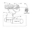
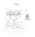
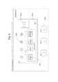
- FIG. 1is a schematic drawing showing a general overview of the system
- FIG. 2is a flowchart describing the method and process for initializing and installing the RCV
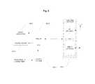
- FIG. 3is a flowchart describing the method and process for initializing and installing the CCU
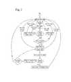
- FIG. 4is a flowchart describing the method and process for authorizing delivery of petroleum products at a retail gas station using the system of the described embodiments;
- FIG. 5is an authorized delivery audible alerts state diagram
- FIG. 6is a front-panel illustration CCU
- FIG. 7is a physical view of the RCV installed in a spill container
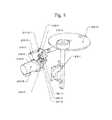
- FIG. 8is a detailed view of the RCV components and locking mechanism
- FIG. 9is a block diagram of the CCU
- FIG. 10is a block diagram of the RCV
- FIG. 11is a block diagram of the PTDU.
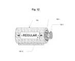
- FIG. 12is a schematic drawing of the PTDU.
- the inventionincludes methods, systems, computer software and products associated with securing storage tanks against the unauthorized transfer of flowable product from delivery vehicles (e.g., tanker trucks and rail cars) or the unauthorized loading of products from a storage tank into a delivery vehicle.
- delivery vehiclese.g., tanker trucks and rail cars
- the systemis comprised generally of a remote controlled valve (hereinafter, RCV), which is installed at the entry port of a liquid storage tank 210 and controls liquid flow into or out of the liquid storage tank 200 .
- RCVremote controlled valve
- a command and control unit (hereinafter, CCU) 120is installed in the cabin 110 of a tanker truck 100 or in a handheld mobile device, which controls the delivery process and includes product type push buttons that open the RCV to full flow.
- Other componentsinclude a visual display 120 - 2 , embedded audible alarm 120 - 3 to report on delivery status, RCV status, and system error indicator 102 - 5 .
- a tankerhas several compartments, each containing a specific product.
- Product type display units (hereinafter, PTDUs) 160are installed next to each compartment dispensing port 130 .
- the PTDU 160is manually set at the fuel depot station by the delivery person, which typically is the tanker truck driver, to display the type of product in the associated compartment (e.g., diesel, regular gasoline, etc.) at the time of product loading with optional active components that will communicate the product type to the CCU.
- the product type push buttoncan be also embedded in the PTDU 160 - 2 .
- Each RCVcarries saved information about the storage tank volume and product type. The delivery person will be required to confirm that the product type for delivery is the same type as the one in the storage tank prior to the delivery by pressing the correct fuel type push button.
- this processcan be replaced by an automatic process with a front end interface 160 - 5 (RF or wired), assuming the information about each compartment product type will be stored during the loading time at the fuel depot by means of retrieving the fuel depot loading arms at the time of loading.
- a communication link between the CCU and the RCVensures that only a pre-authorized CCU is granted access privileges to unload fuel into a liquid storage tank.
- An RCVis prepared and installed in accordance with the process, method and computer program shown in FIG. 2 .
- operational information for each RCVis registered in the logistics center database 300 ( FIG. 1 ) (S 2 ).
- the RCVis programmed with an RCV unique ID number, an operational password, gas station locations, fuel type, tank volume, and administrative password, etc. (S 3 ).
- the operational information from the logistics center databaseis loaded in the RCV database (S 4 ).
- the RCVis then installed at the entry port of the underground tank at the gas station in compliance with its embedded data (S 5 ).
- the RCVis mechanically compatible for integration with common top seal adaptors and is installed at the entry port of the fuel storage tank. After installation, access to the storage tank is blocked and can be opened only in response to an authorized CCU “Open” command.
- the CCUis initialized at the logistics center and installed in the tanker's cabin or in a mobile hand-held terminal.
- the preparation and implementationis achieved in accordance with the process, method and computer program shown in FIG. 3 .
- CCU initializationis started in step S 10 , and the operational information for each CCU is registered in the logistics center database (S 11 ).
- Operational dataincludes CCU ID number, truck ID, a list of served gas stations with RCV ID numbers and associated passwords, etc. (S 12 ).
- the CCU's databaseis loaded with the operational information from the logistics center database (S 13 ), and the CCU is installed in the truck cabin and operation is validated (S 14 ).
- the Logistics Centerprovides a unique identification code for each RCV and CCU.
- the CCUis loaded with a list of gas stations' passwords where that tanker is certified for delivery.
- the passwordsare loaded into the CCU's non-volatile memory and therefore protected against power failure.
- FIG. 4shows the step-by-step operational procedures of the invention.
- FIG. 9is a schematic block diagram of the CCU.
- the electronic circuitryis comprised of a Front End Interface 120 - 7 (RF or wired), RISC ⁇ P system 120 - 6 loaded with an operational program and database, a Power System 120 - 5 , which receives its power from the tanker truck's battery; and a front panel that is comprised of visual indicators 120 - 2 and an audible alarm 120 - 3 .
- the CCUis turned on at the retail gas station. Once operational with a communications medium (RF or Wired) in place, the CCU starts searching for RCVs, and the operational process proceeds according to FIG. 4 .
- RFcommunications medium
- the PTDU 160( FIG. 11 ) is installed on the tanker truck next to each compartment dispensing port.
- the basic PTDUis a mechanical indicator, widely used today in the fuel delivery industry and set by the driver at the fuel depot to remind him the type of product that was loaded into the specific compartment.
- the PTDU discussed in this inventionis an optional accessory to the CCU, and it is comprised of (1) a display 160 - 10 showing the product type stored in the linked compartment, (2) a selection knob 160 - 1 for selecting the product type to display at the time of product loading, and (3) a push button 160 - 2 via a power converter 160 - 3 that sends a command to the CCU to open or close the RCV along with the product type shown on the display.
- the CCUcould also be implemented in a mobile hand-held device.
- the fuel type push buttonscan be installed at the PTDU, which is operationally convenient, and in which case it will constitute a “distributed” CCU.
- the RCVis a low-power electromechanical valve system, controlled by an authorized CCU, and designed to work with petroleum products and other hazardous liquids.
- the RCVis installed at the entry port of an underground liquid storage tank. In the gas station application, it is installed inside a spill container 210 - 19 , screwed in between the bottom of the spill container at one end and a top seal adaptor at the other end.
- FIGS. 7 and 8show the RCV's physical layout
- FIG. 10is a schematic block diagram.
- the RCV's mechanical partsare comprised from a disk flap 210 - 10 .
- the flapcan be in an opened (90°) position or closed (0°) position (as shown in FIGS. 7 and 8 ).
- the flapis connected at its axis to a shaft or axle 210 - 11 .
- the shaftprovides a lock mechanism for the flap when it is in opened or closed positions and also has two magnets 210 - 12 that pull ferromagnetic read switches 210 - 13 to report that the flap is opened, closed or half way open.
- the shaftis moved by a cam 210 - 14 that is connected to a small electric motor 210 - 18 through a spring transmission 210 - 20 that preserves the energy in case of mechanical obstruction to the flap to allow the motor to shut down, while waiting for the mechanical obstruction to be removed.
- the axle 210 - 11 of the disk flapis secured to a cam plate 210 - 14 , which includes a cam slot therein.
- a cam driverincludes a cam pin disposed in the cam slot. The cam pin and slot arrangement serves to lock the disk flap in either the closed position or the opened position.
- a motor arm 210 - 15is connected to the other side of the transmission spring and is also equipped with a magnet 210 - 16 that activates ferromagnetic read switches 210 - 17 to indicate a max position of the motor, and power to the motor can be shut down.
- the cam driveris coupled with the motor via the spring transmission.
- the motoris operable to displace the spring transmission from a relaxed state to a compressed state regardless of a position of the disk flap.
- the spring transmissionis configured such that a force of the spring transmission in the compressed state is sufficient to displace the disk flap from/to the opened position to/from the closed position.
- electronic parts of the RCVinclude an RF or wired Front End Interface 210 - 7 , ⁇ P system 210 - 9 loaded with an operational program and database, and a valve 210 - 2 , whose open/closed status is controlled by a low-power drive 210 - 3 .
- the low power driveis activated by an electrical command sent from the RISC ⁇ P following a request from an authorized CCU.
- the RCVis powered by an internal battery 210 - 6 .
- the systemhas two modes of operations: (a) Delivery Mode and (b) Service mode.
- Delivery Modethe RCV's drop elbow sensor 210 - 1 detects a drop elbow 150 attached to the top seal adaptor for more than few seconds steadily.
- the RCV internal circuitryis activated, and the system attempts to establish communication with the CCU.
- the delivery processis performed according to FIG. 4 (described below).
- the valveIn the service mode, the valve may be opened for a limited time for maintenance purposes, e.g., measuring liquid level using a measuring rod.
- the maintenance personwill have a service version of the CCU that would allow opening the valve for a short time.
- the service mode operational processis described in FIG. 4 .
- the valveis normally closed, with liquid flow blocked. No power is required to hold the valve in this position.
- the valveis bi-directional for liquid flow.
- a closed valveis capable to allow controlled leakage into the underground. This can be accomplished by the size and/or shape of the valve relative to the product entry port. This capability is required to allow a return of a fuel sample taken for analysis purposes, without requiring opening the valve. This rate of controlled leakage should be low enough to cause no product mixing issues in the delivery mode if by mistake somebody is trying to deliver the wrong fuel type.
- FIGS. 4 and 5show operational processes relating to product delivery with the system of the described embodiments.
- deliveryis started in step S 20 , and a tanker truck 100 arrives at the gas station with a delivery order and parks next to the station's fuel tank entry ports (S 21 ).
- the delivery personuncovers and connects the vapor return port to the tanker vapor return port (S 22 ).
- the storage tank entry portis uncovered, the cap is removed, and the drop elbow is connected to the top seal adapter to connect the 4 ′′ hose 140 between the tanker's compartment API and top seal adapters (S 23 ).
- step S 24If the RCV senses the drop elbow transition (YES in S 24 ), the RCV with drop elbow connected enters into active mode and sends its location and ID to the CCU (S 25 ). After receiving the RCV's location and ID, if the RCV is on the CCU's authorized list (YES in S 26 ), the CCU sends the location's password to the RCV (S 27 ). If the RCV is not on the CCU's authorized list (NO in S 26 ), the RCV returns to sleep mode (S 28 ), and the process returns to step S 24 . In step S 24 , if the RCV does not detect the drop elbow transition (NO in S 24 ), the RCV remains closed, and its electronic circuitry stays in sleep mode (S 29 ). The system then waits until the drop elbow transition is detected.
- the RCVdetermines whether the password from the CCU is correct, and if so (YES in S 30 ), the system determines whether a time period that the drop elbow switch was on was less than a preset period, e.g., 3 seconds (S 42 ). If so, (YES in S 42 ), the system opens the valve in the service mode (S 43 ) and closes the valve (S 44 ) if the drop elbow switch is on or if the service mode time delay has passed.
- a preset periode.g. 3 seconds
- the systemchecks whether any other RCV is in active delivery (S 31 ) with a fuel type that is different from the one requested by the CCU (the system can allow for more than one delivery at the same time if the fuel type (or product) of the second delivery is identical to the active delivery and also assuming that the CCU has an additional fuel type indicator and push button (i.e., “resources”) for that type of fuel). If so (YES in S 31 ), the system waits until the active delivery for the other RCV is completed (S 45 ). If the password is incorrect (NO in S 30 ), the process returns to step S 28 , and the RCV returns to sleep mode.
- the systemchecks whether the CCU has enough resources to manage the delivery (S 46 ). If not (NO in S 46 ), the process goes to step S 45 , and if so (YES in S 46 ), the CCU display blinks a product type LED red, and an audible alarm alerts that the RCV is closed (S 32 ). The delivery person verifies that the blinking product-type LED matches the product type displayed on the PTDU and presses the fuel type pushbutton to start delivery (S 33 ).
- the CCUissues an “open valve” command to the RCV, turns off the audible alarm and visual alert, turns the product type LED to solid green, and product delivery commences (S 35 ). If the requested product type does not match the RCV product type (NO in S 34 ), a rejection tone sounds (S 36 ) and the process returns to step S 32 .
- step S 37the delivery person disconnects the drop elbow (S 37 ). With the drop elbow disconnected, the RCV wakes up and sends a completion message to the CCU and begins a countdown (e.g., one minute) to close the valve (S 38 ). If a “close” command from the CCU is received or the countdown limit is completed (YES in S 39 ), the RCV is closed and enters the sleep mode (S 40 ). The system waits for a “close” command from the CCU or completion of the time out period. In step S 41 , the system checks whether a drop elbow is connected, and if not (NO in S 41 ), delivery is complete. If a drop elbow is connected (YES in S 41 ), the process returns to step S 25 .
- FIG. 5illustrates operational processes relating to alert sounds by the CCU to notify the delivery person on exceptions that occur during the unloading process.
- the alarmmay be provided with varying tones to signify different errors, problems or successes.
- the alarmmay sound a drop elbow engaged tone.
- An error tonemay be sounded if an error condition is detected, and an alarm tone may be sounded if an alarm condition is detected.
- the alarmmay similarly include warning beats when the RCV is closed with the drop elbow engaged. After a user requests that the valve be opened, if the request is accepted, the alarm can sound an “acceptance” tone; otherwise, the alarm can sound a “rejection” tone. At that time, if the drop elbow is removed, the buzzer/alarm is silenced. If the drop elbow remains detected, the RCV closed warning beeps continue until an open valve request is accepted.
- the CCUis also designed to collect RCV maintenance and operational status at the station and will store that data in its internal memory to support product maintenance.
- the invention and the operational process described aboveresult in increased distributor revenue, improved product quality, the elimination of improper-product delivery, and insurance cost savings.
- the described systemserves to prevent the unauthorized delivery of product, allow authorized delivery, and control the flow of product at the entry port of a bulk storage tank.
- the systemprevents an unauthorized delivery vehicle that is hauling a product from loading or unloading cargo while enabling an authorized delivery vehicle to unload or load authorized cargo with minimal interruption.
- the described embodimentsare most preferably deployed in the area of fuel distribution, but the embodiments are equally applicable to any other product that involves controlling the transfer of product into or out of a bulk storage tank and a delivery vehicle, such as a tanker truck or rail car.
Landscapes
- Engineering & Computer Science (AREA)
- Mechanical Engineering (AREA)
- Business, Economics & Management (AREA)
- Physics & Mathematics (AREA)
- General Physics & Mathematics (AREA)
- Economics (AREA)
- Automation & Control Theory (AREA)
- Human Resources & Organizations (AREA)
- Theoretical Computer Science (AREA)
- Strategic Management (AREA)
- Tourism & Hospitality (AREA)
- Operations Research (AREA)
- General Business, Economics & Management (AREA)
- Marketing (AREA)
- Quality & Reliability (AREA)
- Entrepreneurship & Innovation (AREA)
- Development Economics (AREA)
- Human Computer Interaction (AREA)
- Manufacturing & Machinery (AREA)
- Management, Administration, Business Operations System, And Electronic Commerce (AREA)
- Loading And Unloading Of Fuel Tanks Or Ships (AREA)
Abstract
Description
Claims (10)
Priority Applications (3)
| Application Number | Priority Date | Filing Date | Title |
|---|---|---|---|
| US15/966,200US10585442B2 (en) | 2011-08-11 | 2018-04-30 | Securing product storage tanks against unauthorized delivery |
| US16/682,244US11194351B2 (en) | 2011-08-11 | 2019-11-13 | Securing product storage tanks against unauthorized delivery |
| US17/543,405US11860653B2 (en) | 2011-08-11 | 2021-12-06 | Preventing contamination in a bulk liquid storage tank |
Applications Claiming Priority (5)
| Application Number | Priority Date | Filing Date | Title |
|---|---|---|---|
| US201161522502P | 2011-08-11 | 2011-08-11 | |
| PCT/US2012/050287WO2013023129A1 (en) | 2011-08-11 | 2012-08-10 | Securing product storage tanks against unauthorized delivery |
| US201314117562A | 2013-11-13 | 2013-11-13 | |
| US15/358,736US9964962B2 (en) | 2011-08-11 | 2016-11-22 | Preventing contamination in a bulk liquid storage tank |
| US15/966,200US10585442B2 (en) | 2011-08-11 | 2018-04-30 | Securing product storage tanks against unauthorized delivery |
Related Parent Applications (1)
| Application Number | Title | Priority Date | Filing Date |
|---|---|---|---|
| US15/358,736ContinuationUS9964962B2 (en) | 2011-08-11 | 2016-11-22 | Preventing contamination in a bulk liquid storage tank |
Related Child Applications (1)
| Application Number | Title | Priority Date | Filing Date |
|---|---|---|---|
| US16/682,244ContinuationUS11194351B2 (en) | 2011-08-11 | 2019-11-13 | Securing product storage tanks against unauthorized delivery |
Publications (2)
| Publication Number | Publication Date |
|---|---|
| US20180246534A1 US20180246534A1 (en) | 2018-08-30 |
| US10585442B2true US10585442B2 (en) | 2020-03-10 |
Family
ID=47668983
Family Applications (5)
| Application Number | Title | Priority Date | Filing Date |
|---|---|---|---|
| US14/117,562Active2033-11-11US9523978B2 (en) | 2011-08-11 | 2012-08-10 | Securing product storage tanks against unauthorized delivery |
| US15/358,736ActiveUS9964962B2 (en) | 2011-08-11 | 2016-11-22 | Preventing contamination in a bulk liquid storage tank |
| US15/966,200Active2032-09-12US10585442B2 (en) | 2011-08-11 | 2018-04-30 | Securing product storage tanks against unauthorized delivery |
| US16/682,244ActiveUS11194351B2 (en) | 2011-08-11 | 2019-11-13 | Securing product storage tanks against unauthorized delivery |
| US17/543,405ActiveUS11860653B2 (en) | 2011-08-11 | 2021-12-06 | Preventing contamination in a bulk liquid storage tank |
Family Applications Before (2)
| Application Number | Title | Priority Date | Filing Date |
|---|---|---|---|
| US14/117,562Active2033-11-11US9523978B2 (en) | 2011-08-11 | 2012-08-10 | Securing product storage tanks against unauthorized delivery |
| US15/358,736ActiveUS9964962B2 (en) | 2011-08-11 | 2016-11-22 | Preventing contamination in a bulk liquid storage tank |
Family Applications After (2)
| Application Number | Title | Priority Date | Filing Date |
|---|---|---|---|
| US16/682,244ActiveUS11194351B2 (en) | 2011-08-11 | 2019-11-13 | Securing product storage tanks against unauthorized delivery |
| US17/543,405ActiveUS11860653B2 (en) | 2011-08-11 | 2021-12-06 | Preventing contamination in a bulk liquid storage tank |
Country Status (2)
| Country | Link |
|---|---|
| US (5) | US9523978B2 (en) |
| WO (1) | WO2013023129A1 (en) |
Cited By (1)
| Publication number | Priority date | Publication date | Assignee | Title |
|---|---|---|---|---|
| US11860653B2 (en) | 2011-08-11 | 2024-01-02 | Knappco, LLC | Preventing contamination in a bulk liquid storage tank |
Families Citing this family (12)
| Publication number | Priority date | Publication date | Assignee | Title |
|---|---|---|---|---|
| FR2992306B1 (en)* | 2012-06-20 | 2014-06-20 | Eurocopter France | PRESSURE FILLING SYSTEM OF A TANK, AND AN AIRCRAFT |
| EP2925667B1 (en) | 2012-11-08 | 2018-01-17 | Delaware Capital Formation, Inc. | Cross contamination control systems with fluid product id sensors |
| US10108936B1 (en) | 2013-12-13 | 2018-10-23 | Robert P. Garner | Electronic run ticket |
| US10207912B2 (en)* | 2014-11-07 | 2019-02-19 | Knappco Corporation | Crossover protection system graphical user interfaces |
| US10407296B2 (en) | 2016-10-12 | 2019-09-10 | Knappco Corporation | Optical fluid sensors for cross contamination control systems |
| US11537108B2 (en)* | 2017-08-11 | 2022-12-27 | Clariant International Ltd. | Systems and methods for mobile resource delivery and management |
| CA3077357A1 (en) | 2017-10-09 | 2019-04-18 | Knappco, LLC | Control systems for liquid product delivery vehicles |
| US10794049B2 (en) | 2018-01-24 | 2020-10-06 | ENASI Industries Inc. | Fluid management/control system |
| TR201921344A2 (en)* | 2019-12-24 | 2020-06-22 | Bulgurcu Berkehan | ELECTRONIC FUEL FILLING SYSTEM WITH INCREASED SAFETY |
| MX2020004235A (en)* | 2020-04-23 | 2022-01-14 | Edison Effect Company Sapi De Cv | System for the supply, monitoring, and control of fluids from sources of supply to fixed locations. |
| US11034574B1 (en)* | 2020-10-16 | 2021-06-15 | Brent Sisson | Fuel transport sensor system |
| US11866321B1 (en)* | 2021-04-12 | 2024-01-09 | Magellan Midstream Partners, L.P. | Fuel supply chain management system and method for integration of retail gas station, carrier tank trucks, and fuel terminal storage truck racks |
Citations (31)
| Publication number | Priority date | Publication date | Assignee | Title |
|---|---|---|---|---|
| US2620822A (en) | 1947-12-13 | 1952-12-09 | Russel A Peterson | Lock valve for fuel tanks |
| US3522670A (en)* | 1967-07-11 | 1970-08-04 | Newport News S & D Co | Apparatus for underwater mining |
| US3822866A (en) | 1971-09-15 | 1974-07-09 | Daester Fairtec Ag | Feeding, weighing and mixing apparatus |
| US4254328A (en)* | 1978-05-31 | 1981-03-03 | Ferranti Limited | Dispensing preset amounts of a product |
| US4553573A (en)* | 1983-10-20 | 1985-11-19 | Pepsico Inc. | Bulk syrup delivery system |
| US4658857A (en) | 1985-09-20 | 1987-04-21 | Surgeaco, Incorporated | Control valve with split disc |
| US4690306A (en) | 1985-08-12 | 1987-09-01 | Ciba-Geigy Corporation | Dispensing device for storing and applying at least one liquid or pasty substance |
| US4830230A (en)* | 1987-06-22 | 1989-05-16 | Marlen Research Corporation | Hydraulically controlled portioner apparatus |
| US4932005A (en)* | 1983-01-04 | 1990-06-05 | Birdwell J C | Fluid means for data transmission |
| US5222027A (en)* | 1990-12-14 | 1993-06-22 | Titan Industries, Inc. | Injector communications system |
| US5359522A (en)* | 1990-05-09 | 1994-10-25 | Ryan Michael C | Fluid delivery control apparatus |
| US5420775A (en)* | 1993-01-15 | 1995-05-30 | Thomas Industries, Inc. | Spray shield die cut from fixture carton flap |
| US5590812A (en)* | 1994-04-18 | 1997-01-07 | Fuji Electric Co., Ltd. | Product-delivery device for automatic vending machines |
| US6347723B1 (en)* | 1997-09-22 | 2002-02-19 | Bartec Componenten Und Systeme Gmbh | Method and security system for securing a flowable good |
| US6449869B1 (en)* | 1998-09-24 | 2002-09-17 | Glatt Systemtechnik Dresden Gmbh | Device and method for drying pourable products |
| US6611755B1 (en)* | 1999-12-19 | 2003-08-26 | Trimble Navigation Ltd. | Vehicle tracking, communication and fleet management system |
| US20050070391A1 (en)* | 2002-05-20 | 2005-03-31 | Folsom Technologies, Inc. | Hydraulic torque vectoring differential |
| US7028865B2 (en)* | 2002-02-05 | 2006-04-18 | Rpc Wiko Gmbh & Co. Kg | Dispenser for flowable products |
| US20060157149A1 (en) | 2005-01-14 | 2006-07-20 | Hillam John D | Preventing unauthorized delivery of liquid product ot a liquid product storage tank |
| US20060206246A1 (en)* | 2004-10-28 | 2006-09-14 | Walker Richard C | Second national / international management and security system for responsible global resourcing through technical management to brige cultural and economic desparity |
| US7292993B2 (en)* | 2001-02-08 | 2007-11-06 | Uzzo Anthony M | System for remotely managing bulk product storage |
| US20080091309A1 (en)* | 1998-01-15 | 2008-04-17 | Walker Richard C | Electrically controlled automated devices to operate, slow, guide, stop and secure, equipment and machinery for the purpose of controlling their unsafe, unattended, unauthorized, unlawful hazardous and/or legal use, with remote control and accountability worldwide |
| US20090293654A1 (en) | 2008-05-30 | 2009-12-03 | Woodward Governor Company | Tortionally Stiff, Thermally Isolating Shaft Coupling with Multiple Degrees of Freedom to Accommodate Misalignment |
| US20090314384A1 (en)* | 2008-06-23 | 2009-12-24 | Brakefield Michael C | Fuel transferring system and method of use |
| US20110120589A1 (en)* | 2009-05-20 | 2011-05-26 | Evans Kenneth R | Liquid transportation |
| US20110287166A1 (en)* | 2003-08-01 | 2011-11-24 | Driam Anlagenbau Gmbh | Method and device for the continuous coating of cores by means of a dragee making apparatus |
| US20120150344A1 (en)* | 2010-12-08 | 2012-06-14 | Danaher Uk Industries Limited | Fuel dispenser flow meter sensor fraud prevention |
| US9133013B2 (en)* | 2011-06-03 | 2015-09-15 | Curtis Roys | Method and structure for prevention of incorrect fueling operations |
| US20160045841A1 (en)* | 2013-03-15 | 2016-02-18 | Transtar Group, Ltd. | New and improved system for processing various chemicals and materials |
| US20160117636A1 (en)* | 2013-10-28 | 2016-04-28 | Nick MILLER | Systems and methods for fueling motor vehicles |
| US9523978B2 (en)* | 2011-08-11 | 2016-12-20 | Soneco Llc | Securing product storage tanks against unauthorized delivery |
Family Cites Families (9)
| Publication number | Priority date | Publication date | Assignee | Title |
|---|---|---|---|---|
| US4530463A (en)* | 1982-08-05 | 1985-07-23 | Hiniker Company | Control method and apparatus for liquid distributor |
| US5139044A (en)* | 1991-08-15 | 1992-08-18 | Otten Bernard J | Fluid control system |
| US5960840A (en)* | 1998-04-27 | 1999-10-05 | Link Research And Development, Inc. | Controlled product dispensing system |
| AU2003245485A1 (en)* | 2002-06-12 | 2003-12-31 | The Water System Group, Inc. | Purified water supply system |
| MX2007002937A (en)* | 2004-09-13 | 2008-03-05 | Argent Marine Operations Inc | System and process for transporting lng by non-self-propelled marine lng carrier. |
| US7455225B1 (en)* | 2005-02-22 | 2008-11-25 | Sabioso, Inc. | Method and system for monitoring and controlling goods while in transit |
| JP2009536097A (en)* | 2006-05-05 | 2009-10-08 | プラスコエナジー アイピー ホールディングス、エス.エル.、ビルバオ、シャフハウゼン ブランチ | Gas homogenization system |
| US7725273B2 (en)* | 2006-11-17 | 2010-05-25 | Jannotta Louis J | Apparatus for monitoring height of liquid in storage tank |
| US20080128453A1 (en)* | 2006-11-30 | 2008-06-05 | Flint Loc Security Llc | Dispenser security system |
- 2012
- 2012-08-10USUS14/117,562patent/US9523978B2/enactiveActive
- 2012-08-10WOPCT/US2012/050287patent/WO2013023129A1/enactiveApplication Filing
- 2016
- 2016-11-22USUS15/358,736patent/US9964962B2/enactiveActive
- 2018
- 2018-04-30USUS15/966,200patent/US10585442B2/enactiveActive
- 2019
- 2019-11-13USUS16/682,244patent/US11194351B2/enactiveActive
- 2021
- 2021-12-06USUS17/543,405patent/US11860653B2/enactiveActive
Patent Citations (33)
| Publication number | Priority date | Publication date | Assignee | Title |
|---|---|---|---|---|
| US2620822A (en) | 1947-12-13 | 1952-12-09 | Russel A Peterson | Lock valve for fuel tanks |
| US3522670A (en)* | 1967-07-11 | 1970-08-04 | Newport News S & D Co | Apparatus for underwater mining |
| US3822866A (en) | 1971-09-15 | 1974-07-09 | Daester Fairtec Ag | Feeding, weighing and mixing apparatus |
| US4254328A (en)* | 1978-05-31 | 1981-03-03 | Ferranti Limited | Dispensing preset amounts of a product |
| US4932005A (en)* | 1983-01-04 | 1990-06-05 | Birdwell J C | Fluid means for data transmission |
| US4553573A (en)* | 1983-10-20 | 1985-11-19 | Pepsico Inc. | Bulk syrup delivery system |
| US4690306A (en) | 1985-08-12 | 1987-09-01 | Ciba-Geigy Corporation | Dispensing device for storing and applying at least one liquid or pasty substance |
| US4658857A (en) | 1985-09-20 | 1987-04-21 | Surgeaco, Incorporated | Control valve with split disc |
| US4830230A (en)* | 1987-06-22 | 1989-05-16 | Marlen Research Corporation | Hydraulically controlled portioner apparatus |
| US5359522A (en)* | 1990-05-09 | 1994-10-25 | Ryan Michael C | Fluid delivery control apparatus |
| US5222027A (en)* | 1990-12-14 | 1993-06-22 | Titan Industries, Inc. | Injector communications system |
| US5420775A (en)* | 1993-01-15 | 1995-05-30 | Thomas Industries, Inc. | Spray shield die cut from fixture carton flap |
| US5590812A (en)* | 1994-04-18 | 1997-01-07 | Fuji Electric Co., Ltd. | Product-delivery device for automatic vending machines |
| US6347723B1 (en)* | 1997-09-22 | 2002-02-19 | Bartec Componenten Und Systeme Gmbh | Method and security system for securing a flowable good |
| US20080091309A1 (en)* | 1998-01-15 | 2008-04-17 | Walker Richard C | Electrically controlled automated devices to operate, slow, guide, stop and secure, equipment and machinery for the purpose of controlling their unsafe, unattended, unauthorized, unlawful hazardous and/or legal use, with remote control and accountability worldwide |
| US6449869B1 (en)* | 1998-09-24 | 2002-09-17 | Glatt Systemtechnik Dresden Gmbh | Device and method for drying pourable products |
| US6611755B1 (en)* | 1999-12-19 | 2003-08-26 | Trimble Navigation Ltd. | Vehicle tracking, communication and fleet management system |
| US7292993B2 (en)* | 2001-02-08 | 2007-11-06 | Uzzo Anthony M | System for remotely managing bulk product storage |
| US7028865B2 (en)* | 2002-02-05 | 2006-04-18 | Rpc Wiko Gmbh & Co. Kg | Dispenser for flowable products |
| US20050070391A1 (en)* | 2002-05-20 | 2005-03-31 | Folsom Technologies, Inc. | Hydraulic torque vectoring differential |
| US20110287166A1 (en)* | 2003-08-01 | 2011-11-24 | Driam Anlagenbau Gmbh | Method and device for the continuous coating of cores by means of a dragee making apparatus |
| US20060206246A1 (en)* | 2004-10-28 | 2006-09-14 | Walker Richard C | Second national / international management and security system for responsible global resourcing through technical management to brige cultural and economic desparity |
| US20060157149A1 (en) | 2005-01-14 | 2006-07-20 | Hillam John D | Preventing unauthorized delivery of liquid product ot a liquid product storage tank |
| US20090293654A1 (en) | 2008-05-30 | 2009-12-03 | Woodward Governor Company | Tortionally Stiff, Thermally Isolating Shaft Coupling with Multiple Degrees of Freedom to Accommodate Misalignment |
| US20090314384A1 (en)* | 2008-06-23 | 2009-12-24 | Brakefield Michael C | Fuel transferring system and method of use |
| US8905089B2 (en)* | 2009-05-20 | 2014-12-09 | Chs Inc. | Liquid transportation |
| US20110120589A1 (en)* | 2009-05-20 | 2011-05-26 | Evans Kenneth R | Liquid transportation |
| US20120150344A1 (en)* | 2010-12-08 | 2012-06-14 | Danaher Uk Industries Limited | Fuel dispenser flow meter sensor fraud prevention |
| US9133013B2 (en)* | 2011-06-03 | 2015-09-15 | Curtis Roys | Method and structure for prevention of incorrect fueling operations |
| US9523978B2 (en)* | 2011-08-11 | 2016-12-20 | Soneco Llc | Securing product storage tanks against unauthorized delivery |
| US9964962B2 (en)* | 2011-08-11 | 2018-05-08 | Soneco Llc | Preventing contamination in a bulk liquid storage tank |
| US20160045841A1 (en)* | 2013-03-15 | 2016-02-18 | Transtar Group, Ltd. | New and improved system for processing various chemicals and materials |
| US20160117636A1 (en)* | 2013-10-28 | 2016-04-28 | Nick MILLER | Systems and methods for fueling motor vehicles |
Cited By (1)
| Publication number | Priority date | Publication date | Assignee | Title |
|---|---|---|---|---|
| US11860653B2 (en) | 2011-08-11 | 2024-01-02 | Knappco, LLC | Preventing contamination in a bulk liquid storage tank |
Also Published As
| Publication number | Publication date |
|---|---|
| US20180246534A1 (en) | 2018-08-30 |
| US11194351B2 (en) | 2021-12-07 |
| US20170075362A1 (en) | 2017-03-16 |
| US9964962B2 (en) | 2018-05-08 |
| US20140316589A1 (en) | 2014-10-23 |
| US9523978B2 (en) | 2016-12-20 |
| US20220091621A1 (en) | 2022-03-24 |
| US11860653B2 (en) | 2024-01-02 |
| WO2013023129A1 (en) | 2013-02-14 |
| US20200081460A1 (en) | 2020-03-12 |
Similar Documents
| Publication | Publication Date | Title |
|---|---|---|
| US11860653B2 (en) | Preventing contamination in a bulk liquid storage tank | |
| US10534374B2 (en) | Cross contamination control systems with fluid product ID sensors | |
| US6363299B1 (en) | Dispenser system for preventing unauthorized fueling | |
| EP1594796B1 (en) | Apparatus for dispensing a substance | |
| US10738943B2 (en) | Filling station for gas bottles and filling method | |
| EP0736484B1 (en) | Fluid delivery control nozzle | |
| US5359522A (en) | Fluid delivery control apparatus | |
| HK1254297A1 (en) | Method for preventing cross contamination of fluids | |
| WO2009132347A1 (en) | Fuel delivery pathway control | |
| US10963855B2 (en) | Portable vehicle fueling kiosk | |
| JPH0655635B2 (en) | Carbon dioxide aeration and pressure supply valve | |
| US20190077579A1 (en) | Automated tamper proof fluid dispensing arrangement | |
| WO2011123938A1 (en) | Tank identification delivery interlock system and method | |
| CA2983752A1 (en) | Automated tamper proof fluid dispensing arrangement | |
| JP2020125145A (en) | Fuel oil delivery system and server |
Legal Events
| Date | Code | Title | Description |
|---|---|---|---|
| AS | Assignment | Owner name:SONECO LLC, MARYLAND Free format text:ASSIGNMENT OF ASSIGNORS INTEREST;ASSIGNOR:LICHTASH, AVRAHAM SHMUEL;REEL/FRAME:045666/0817 Effective date:20161118 | |
| FEPP | Fee payment procedure | Free format text:ENTITY STATUS SET TO UNDISCOUNTED (ORIGINAL EVENT CODE: BIG.); ENTITY STATUS OF PATENT OWNER: SMALL ENTITY | |
| FEPP | Fee payment procedure | Free format text:ENTITY STATUS SET TO SMALL (ORIGINAL EVENT CODE: SMAL); ENTITY STATUS OF PATENT OWNER: SMALL ENTITY | |
| STPP | Information on status: patent application and granting procedure in general | Free format text:DOCKETED NEW CASE - READY FOR EXAMINATION | |
| STPP | Information on status: patent application and granting procedure in general | Free format text:NON FINAL ACTION MAILED | |
| STPP | Information on status: patent application and granting procedure in general | Free format text:RESPONSE TO NON-FINAL OFFICE ACTION ENTERED AND FORWARDED TO EXAMINER | |
| STPP | Information on status: patent application and granting procedure in general | Free format text:NOTICE OF ALLOWANCE MAILED -- APPLICATION RECEIVED IN OFFICE OF PUBLICATIONS | |
| STPP | Information on status: patent application and granting procedure in general | Free format text:NOTICE OF ALLOWANCE MAILED -- APPLICATION RECEIVED IN OFFICE OF PUBLICATIONS | |
| STPP | Information on status: patent application and granting procedure in general | Free format text:PUBLICATIONS -- ISSUE FEE PAYMENT VERIFIED | |
| STCF | Information on status: patent grant | Free format text:PATENTED CASE | |
| AS | Assignment | Owner name:OPW, INC., OHIO Free format text:ASSIGNMENT OF ASSIGNORS INTEREST;ASSIGNOR:SONECO LLC;REEL/FRAME:056198/0667 Effective date:20201221 | |
| AS | Assignment | Owner name:KNAPPCO, LLC, OHIO Free format text:ASSIGNMENT OF ASSIGNORS INTEREST;ASSIGNOR:OPW, INC.;REEL/FRAME:056215/0828 Effective date:20210426 | |
| FEPP | Fee payment procedure | Free format text:ENTITY STATUS SET TO UNDISCOUNTED (ORIGINAL EVENT CODE: BIG.); ENTITY STATUS OF PATENT OWNER: LARGE ENTITY | |
| MAFP | Maintenance fee payment | Free format text:PAYMENT OF MAINTENANCE FEE, 4TH YEAR, LARGE ENTITY (ORIGINAL EVENT CODE: M1551); ENTITY STATUS OF PATENT OWNER: LARGE ENTITY Year of fee payment:4 |