US10583439B2 - Hydrodynamic focusing apparatus and methods - Google Patents
Hydrodynamic focusing apparatus and methodsDownload PDFInfo
- Publication number
- US10583439B2 US10583439B2US14/213,800US201414213800AUS10583439B2US 10583439 B2US10583439 B2US 10583439B2US 201414213800 AUS201414213800 AUS 201414213800AUS 10583439 B2US10583439 B2US 10583439B2
- Authority
- US
- United States
- Prior art keywords
- fluid
- focusing
- microfluidic
- channel
- vertical
- Prior art date
- Legal status (The legal status is an assumption and is not a legal conclusion. Google has not performed a legal analysis and makes no representation as to the accuracy of the status listed.)
- Active, expires
Links
- 238000000034methodMethods0.000titledescription14
- 238000009652hydrodynamic focusingMethods0.000titledescription3
- 239000012530fluidSubstances0.000claimsabstractdescription428
- 238000012545processingMethods0.000claimsabstractdescription20
- 239000000758substrateSubstances0.000claimsdescription70
- 239000002245particleSubstances0.000claimsdescription63
- 238000011144upstream manufacturingMethods0.000claimsdescription34
- 238000004891communicationMethods0.000claimsdescription28
- 230000007704transitionEffects0.000claimsdescription10
- 238000007689inspectionMethods0.000claimsdescription6
- 239000000523sampleSubstances0.000description103
- 230000003287optical effectEffects0.000description18
- 210000004027cellAnatomy0.000description16
- 230000004931aggregating effectEffects0.000description12
- 230000005670electromagnetic radiationEffects0.000description10
- 230000007246mechanismEffects0.000description8
- 238000000429assemblyMethods0.000description6
- 230000000712assemblyEffects0.000description6
- 230000008033biological extinctionEffects0.000description5
- 239000007788liquidSubstances0.000description4
- 230000007423decreaseEffects0.000description3
- 238000001514detection methodMethods0.000description3
- 239000011521glassSubstances0.000description3
- 238000004519manufacturing processMethods0.000description3
- 230000008569processEffects0.000description3
- VYPSYNLAJGMNEJ-UHFFFAOYSA-NSilicium dioxideChemical compoundO=[Si]=OVYPSYNLAJGMNEJ-UHFFFAOYSA-N0.000description2
- 238000004458analytical methodMethods0.000description2
- 239000011324beadSubstances0.000description2
- 230000015572biosynthetic processEffects0.000description2
- 230000000295complement effectEffects0.000description2
- 230000001419dependent effectEffects0.000description2
- 239000000463materialSubstances0.000description2
- 229910052751metalInorganic materials0.000description2
- 239000002184metalSubstances0.000description2
- 150000002739metalsChemical class0.000description2
- 238000012986modificationMethods0.000description2
- 230000004048modificationEffects0.000description2
- 238000012544monitoring processMethods0.000description2
- 108090000623proteins and genesProteins0.000description2
- 102000004169proteins and genesHuman genes0.000description2
- 238000007493shaping processMethods0.000description2
- 239000000126substanceSubstances0.000description2
- 238000010897surface acoustic wave methodMethods0.000description2
- 2380000101463D printingMethods0.000description1
- 241000894006BacteriaSpecies0.000description1
- 241000195493CryptophytaSpecies0.000description1
- 229920000089Cyclic olefin copolymerPolymers0.000description1
- 239000004713Cyclic olefin copolymerSubstances0.000description1
- 239000004793PolystyreneSubstances0.000description1
- 240000004808Saccharomyces cerevisiaeSpecies0.000description1
- 241000700605VirusesSpecies0.000description1
- 230000001133accelerationEffects0.000description1
- 230000009471actionEffects0.000description1
- 239000000654additiveSubstances0.000description1
- 230000000996additive effectEffects0.000description1
- 238000003491arrayMethods0.000description1
- 230000009286beneficial effectEffects0.000description1
- 230000008901benefitEffects0.000description1
- 230000005540biological transmissionEffects0.000description1
- 210000004369bloodAnatomy0.000description1
- 239000008280bloodSubstances0.000description1
- 210000001772blood plateletAnatomy0.000description1
- 210000001185bone marrowAnatomy0.000description1
- 239000005352borofloatSubstances0.000description1
- 239000000919ceramicSubstances0.000description1
- 239000003153chemical reaction reagentSubstances0.000description1
- 239000002131composite materialSubstances0.000description1
- 238000004163cytometryMethods0.000description1
- 239000004205dimethyl polysiloxaneSubstances0.000description1
- 235000013870dimethyl polysiloxaneNutrition0.000description1
- BFMYDTVEBKDAKJ-UHFFFAOYSA-Ldisodium;(2',7'-dibromo-3',6'-dioxido-3-oxospiro[2-benzofuran-1,9'-xanthene]-4'-yl)mercury;hydrateChemical compoundO.[Na+].[Na+].O1C(=O)C2=CC=CC=C2C21C1=CC(Br)=C([O-])C([Hg])=C1OC1=C2C=C(Br)C([O-])=C1BFMYDTVEBKDAKJ-UHFFFAOYSA-L0.000description1
- 238000006073displacement reactionMethods0.000description1
- 238000009826distributionMethods0.000description1
- 210000002308embryonic cellAnatomy0.000description1
- -1etc.)Chemical compound0.000description1
- 239000000835fiberSubstances0.000description1
- 239000012634fragmentSubstances0.000description1
- 239000005350fused silica glassSubstances0.000description1
- 239000007789gasSubstances0.000description1
- 238000005286illuminationMethods0.000description1
- 239000007943implantSubstances0.000description1
- 238000002347injectionMethods0.000description1
- 239000007924injectionSubstances0.000description1
- 238000001746injection mouldingMethods0.000description1
- 229910052500inorganic mineralInorganic materials0.000description1
- 230000003993interactionEffects0.000description1
- 238000005304joiningMethods0.000description1
- 210000000265leukocyteAnatomy0.000description1
- 239000002502liposomeSubstances0.000description1
- 238000003754machiningMethods0.000description1
- 238000005259measurementMethods0.000description1
- 239000012528membraneSubstances0.000description1
- 239000011707mineralSubstances0.000description1
- 230000000116mitigating effectEffects0.000description1
- CXQXSVUQTKDNFP-UHFFFAOYSA-NoctamethyltrisiloxaneChemical compoundC[Si](C)(C)O[Si](C)(C)O[Si](C)(C)CCXQXSVUQTKDNFP-UHFFFAOYSA-N0.000description1
- 210000003463organelleAnatomy0.000description1
- 230000037361pathwayEffects0.000description1
- 210000005259peripheral bloodAnatomy0.000description1
- 239000011886peripheral bloodSubstances0.000description1
- 230000002572peristaltic effectEffects0.000description1
- 238000004987plasma desorption mass spectroscopyMethods0.000description1
- 239000004033plasticSubstances0.000description1
- 229920003023plasticPolymers0.000description1
- 229920000435poly(dimethylsiloxane)Polymers0.000description1
- 229920003229poly(methyl methacrylate)Polymers0.000description1
- 239000004417polycarbonateSubstances0.000description1
- 229920000515polycarbonatePolymers0.000description1
- 239000004926polymethyl methacrylateSubstances0.000description1
- 229920002223polystyrenePolymers0.000description1
- 108010030416proteoliposomesProteins0.000description1
- 238000000746purificationMethods0.000description1
- 239000010453quartzSubstances0.000description1
- 230000005855radiationEffects0.000description1
- 230000009467reductionEffects0.000description1
- 230000004044responseEffects0.000description1
- 238000010008shearingMethods0.000description1
- 230000003595spectral effectEffects0.000description1
- 238000012360testing methodMethods0.000description1
- 230000001225therapeutic effectEffects0.000description1
- 238000002560therapeutic procedureMethods0.000description1
- 238000013519translationMethods0.000description1
Images


Classifications
- B—PERFORMING OPERATIONS; TRANSPORTING
- B01—PHYSICAL OR CHEMICAL PROCESSES OR APPARATUS IN GENERAL
- B01L—CHEMICAL OR PHYSICAL LABORATORY APPARATUS FOR GENERAL USE
- B01L3/00—Containers or dishes for laboratory use, e.g. laboratory glassware; Droppers
- B01L3/50—Containers for the purpose of retaining a material to be analysed, e.g. test tubes
- B01L3/502—Containers for the purpose of retaining a material to be analysed, e.g. test tubes with fluid transport, e.g. in multi-compartment structures
- B01L3/5027—Containers for the purpose of retaining a material to be analysed, e.g. test tubes with fluid transport, e.g. in multi-compartment structures by integrated microfluidic structures, i.e. dimensions of channels and chambers are such that surface tension forces are important, e.g. lab-on-a-chip
- B01L3/502769—Containers for the purpose of retaining a material to be analysed, e.g. test tubes with fluid transport, e.g. in multi-compartment structures by integrated microfluidic structures, i.e. dimensions of channels and chambers are such that surface tension forces are important, e.g. lab-on-a-chip characterised by multiphase flow arrangements
- B01L3/502776—Containers for the purpose of retaining a material to be analysed, e.g. test tubes with fluid transport, e.g. in multi-compartment structures by integrated microfluidic structures, i.e. dimensions of channels and chambers are such that surface tension forces are important, e.g. lab-on-a-chip characterised by multiphase flow arrangements specially adapted for focusing or laminating flows
- B01F13/0062—
- B—PERFORMING OPERATIONS; TRANSPORTING
- B01—PHYSICAL OR CHEMICAL PROCESSES OR APPARATUS IN GENERAL
- B01F—MIXING, e.g. DISSOLVING, EMULSIFYING OR DISPERSING
- B01F33/00—Other mixers; Mixing plants; Combinations of mixers
- B01F33/30—Micromixers
- B01F33/301—Micromixers using specific means for arranging the streams to be mixed, e.g. channel geometries or dispositions
- B01F33/3011—Micromixers using specific means for arranging the streams to be mixed, e.g. channel geometries or dispositions using a sheathing stream of a fluid surrounding a central stream of a different fluid, e.g. for reducing the cross-section of the central stream or to produce droplets from the central stream
- F—MECHANICAL ENGINEERING; LIGHTING; HEATING; WEAPONS; BLASTING
- F17—STORING OR DISTRIBUTING GASES OR LIQUIDS
- F17D—PIPE-LINE SYSTEMS; PIPE-LINES
- F17D1/00—Pipe-line systems
- F17D1/08—Pipe-line systems for liquids or viscous products
- F—MECHANICAL ENGINEERING; LIGHTING; HEATING; WEAPONS; BLASTING
- F17—STORING OR DISTRIBUTING GASES OR LIQUIDS
- F17D—PIPE-LINE SYSTEMS; PIPE-LINES
- F17D5/00—Protection or supervision of installations
- G—PHYSICS
- G01—MEASURING; TESTING
- G01N—INVESTIGATING OR ANALYSING MATERIALS BY DETERMINING THEIR CHEMICAL OR PHYSICAL PROPERTIES
- G01N15/00—Investigating characteristics of particles; Investigating permeability, pore-volume or surface-area of porous materials
- G01N15/10—Investigating individual particles
- G01N15/14—Optical investigation techniques, e.g. flow cytometry
- G01N15/1404—Handling flow, e.g. hydrodynamic focusing
- B—PERFORMING OPERATIONS; TRANSPORTING
- B01—PHYSICAL OR CHEMICAL PROCESSES OR APPARATUS IN GENERAL
- B01L—CHEMICAL OR PHYSICAL LABORATORY APPARATUS FOR GENERAL USE
- B01L2200/00—Solutions for specific problems relating to chemical or physical laboratory apparatus
- B01L2200/06—Fluid handling related problems
- B01L2200/0636—Focussing flows, e.g. to laminate flows
- B—PERFORMING OPERATIONS; TRANSPORTING
- B01—PHYSICAL OR CHEMICAL PROCESSES OR APPARATUS IN GENERAL
- B01L—CHEMICAL OR PHYSICAL LABORATORY APPARATUS FOR GENERAL USE
- B01L2300/00—Additional constructional details
- B01L2300/08—Geometry, shape and general structure
- B01L2300/0861—Configuration of multiple channels and/or chambers in a single devices
- B01L2300/0867—Multiple inlets and one sample wells, e.g. mixing, dilution
- F—MECHANICAL ENGINEERING; LIGHTING; HEATING; WEAPONS; BLASTING
- F16—ENGINEERING ELEMENTS AND UNITS; GENERAL MEASURES FOR PRODUCING AND MAINTAINING EFFECTIVE FUNCTIONING OF MACHINES OR INSTALLATIONS; THERMAL INSULATION IN GENERAL
- F16K—VALVES; TAPS; COCKS; ACTUATING-FLOATS; DEVICES FOR VENTING OR AERATING
- F16K99/00—Subject matter not provided for in other groups of this subclass
- F16K2099/0073—Fabrication methods specifically adapted for microvalves
- F16K2099/008—Multi-layer fabrications
- G—PHYSICS
- G01—MEASURING; TESTING
- G01N—INVESTIGATING OR ANALYSING MATERIALS BY DETERMINING THEIR CHEMICAL OR PHYSICAL PROPERTIES
- G01N15/00—Investigating characteristics of particles; Investigating permeability, pore-volume or surface-area of porous materials
- G01N15/10—Investigating individual particles
- G01N15/14—Optical investigation techniques, e.g. flow cytometry
- G01N15/1404—Handling flow, e.g. hydrodynamic focusing
- G01N15/1409—Handling samples, e.g. injecting samples
- G01N2015/1409—
- G—PHYSICS
- G01—MEASURING; TESTING
- G01N—INVESTIGATING OR ANALYSING MATERIALS BY DETERMINING THEIR CHEMICAL OR PHYSICAL PROPERTIES
- G01N15/00—Investigating characteristics of particles; Investigating permeability, pore-volume or surface-area of porous materials
- G01N15/10—Investigating individual particles
- G01N15/14—Optical investigation techniques, e.g. flow cytometry
- G01N15/1404—Handling flow, e.g. hydrodynamic focusing
- G01N15/1409—Handling samples, e.g. injecting samples
- G01N2015/1411—Features of sheath fluids
- G—PHYSICS
- G01—MEASURING; TESTING
- G01N—INVESTIGATING OR ANALYSING MATERIALS BY DETERMINING THEIR CHEMICAL OR PHYSICAL PROPERTIES
- G01N15/00—Investigating characteristics of particles; Investigating permeability, pore-volume or surface-area of porous materials
- G01N15/10—Investigating individual particles
- G01N15/14—Optical investigation techniques, e.g. flow cytometry
- G01N15/1404—Handling flow, e.g. hydrodynamic focusing
- G01N2015/1413—Hydrodynamic focussing
- G—PHYSICS
- G01—MEASURING; TESTING
- G01N—INVESTIGATING OR ANALYSING MATERIALS BY DETERMINING THEIR CHEMICAL OR PHYSICAL PROPERTIES
- G01N2203/00—Investigating strength properties of solid materials by application of mechanical stress
- G01N2203/02—Details not specific for a particular testing method
- G01N2203/026—Specifications of the specimen
- G01N2203/0262—Shape of the specimen
- G01N2203/0264—Beam
- Y—GENERAL TAGGING OF NEW TECHNOLOGICAL DEVELOPMENTS; GENERAL TAGGING OF CROSS-SECTIONAL TECHNOLOGIES SPANNING OVER SEVERAL SECTIONS OF THE IPC; TECHNICAL SUBJECTS COVERED BY FORMER USPC CROSS-REFERENCE ART COLLECTIONS [XRACs] AND DIGESTS
- Y10—TECHNICAL SUBJECTS COVERED BY FORMER USPC
- Y10T—TECHNICAL SUBJECTS COVERED BY FORMER US CLASSIFICATION
- Y10T137/00—Fluid handling
- Y10T137/206—Flow affected by fluid contact, energy field or coanda effect [e.g., pure fluid device or system]
- Y10T137/2076—Utilizing diverse fluids
- Y—GENERAL TAGGING OF NEW TECHNOLOGICAL DEVELOPMENTS; GENERAL TAGGING OF CROSS-SECTIONAL TECHNOLOGIES SPANNING OVER SEVERAL SECTIONS OF THE IPC; TECHNICAL SUBJECTS COVERED BY FORMER USPC CROSS-REFERENCE ART COLLECTIONS [XRACs] AND DIGESTS
- Y10—TECHNICAL SUBJECTS COVERED BY FORMER USPC
- Y10T—TECHNICAL SUBJECTS COVERED BY FORMER US CLASSIFICATION
- Y10T137/00—Fluid handling
- Y10T137/8158—With indicator, register, recorder, alarm or inspection means
- Y10T137/8359—Inspection means
Definitions
- this disclosurerelates to hydrodynamic focusing, in particular, in a microfluidic device. More specifically, the present disclosure relates to systems and methods for producing a sheath flow in a flow channel and, in particular, in a micro channel in a microfluidic device.
- Sheath flowis a particular type of laminar flow in which one layer of sample fluid, or a particle, is surrounded by another layer of focusing fluid on more than one side.
- the process of confining a particle stream in a fluidis referred to as a ‘sheath flow’ configuration.
- a sheath fluidmay envelop and pinch a sample fluid containing a number of particles.
- the flow of the sample fluid containing particles suspended thereinmay be narrowed almost to the outer diameter of particles in the center of the sheath fluid.
- the resulting sheath flowflows in a laminar state within an orifice or channel so that the particles are aligned and accurately pass through an orifice or channel in a single file row.
- Sheath flowis used in many applications where it is preferable to protect particles or fluids by a layer of sheath fluid, for example in applications wherein it is necessary to protect particles from air.
- particles to be sorted or analyzedare usually supplied to a measurement position in a central fluid current, which is surrounded by a particle free liquid sheath.
- Sheath flowis useful because it can position particles with respect to sensors or other components and prevent particles in the center fluid, which is surrounded by the sheath fluid, from touching the sides of the flow channel and thereby prevents clogging of the channel. Sheath flow allows for faster flow velocities and higher throughput of sample material. Faster flow velocity is possible without shredding cells in the center fluid because the sheath fluid protects the cells from potentially high shear forces at the walls of the flow channel.
- a microfluidic particle processing assemblyincluding a substrate and a flow channel formed in the substrate may be provided.
- the flow channelmay include an inlet, a fluid focusing region having an associated fluid focusing feature for focusing a particle within the flow channel, and an inspection region at least partially downstream of the fluid focusing region. Further, the flow channel may have first and second outlets.
- the fluid focusing features of the flow channel focusing regionmay include a core stream forming geometry.
- the core stream forming geometrymay further include a lateral fluid focusing region, a first vertical fluid focusing component, and a second vertical fluid focusing component.
- the first vertical fluid focusing componentmay include a vertical fluid focusing channel and the second vertical fluid focusing component may include a second vertical fluid focusing channel.
- the first vertical fluid focusing component and the second vertical fluid focusing componentmay be in communication with the fluid focusing region in opposite vertical directions.
- the first vertical fluid focusing componentmay provide a first vertical influence and the second vertical fluid focusing component may provide a second vertical influence in the opposite directions as the first vertical influence.
- the flow channelmay further include a sheath inlet in fluid communication with the sheath source.
- a sample inletmay be positioned within a sheath flow created by the sheath inlet to facilitate a co-axial flow of sheath and sample.
- the sample inletmay include a tapered or beveled inlet.
- the flow channelmay have a first width and a first height at the sample inlet.
- the flow channelmay a second width and a second height at a first transition point.
- the height of the flow channelmay be reduced between the sample inlet and the first transition point.
- the flow channelmay have a third width and a third height at a second transition point.
- the height of the flow channelmay remain constant between the first transition point and the second transition point and the width of the flow channel may be reduced between the first transition point and the second transition point.
- the third height and the third width of the flow channelmay be maintained through the inspection region.
- the flow channelmay transition from a square cross section to a rectangular cross section.
- the flow channelmay transition from a circular cross section to an elliptical cross section.
- the microfluidic assemblymay further include a plurality of flow channels as presented herein.
- the fluid focusing feature of the fluid focusing regionmay further include ultrasonic transducers for producing pressure waves in the focusing region of each flow channel.
- the ultrasonic transducersmay be an array of ultrasonic transducers for producing a standing pressure wave along the flow channel.
- a diverting mechanism in communication with the flow channelmay be provided.
- the diverting mechanismmay include a bubble valve.
- the diverting mechanismmay include an array of ultrasonic and/or standing acoustic wave transducers.
- the diverting mechanismmay include interdigitated transducers (IDT).
- a microfluidic chipmay include a substantially planar chip substrate having an upper surface and a lower surface.
- a microfluidic flow channelmay be provided within the chip substrate.
- a first inlet portmay be formed on the upper surface of the chip substrate for receiving a focusing fluid. The first inlet port may be in fluid communication with the microfluidic flow channel.
- the microfluidic flow channelmay include a first focusing fluid inlet configured to introduce focusing fluid from the first inlet port into the microfluidic channel in a first direction, a second focusing fluid inlet configured to introduce focusing fluid from the first inlet port into the microfluidic channel in a second direction, and a third focusing fluid inlet configured to introduce focusing fluid from the first inlet port into the microfluidic channel in a third direction.
- the microfluidic chipmay also include a second inlet port formed on the upper surface of the chip substrate for receiving a focusing fluid.
- the second inlet portmay be in fluid communication with the microfluidic flow channel.
- the microfluidic flow channelmay include a fourth focusing fluid inlet configured to introduce focusing fluid from the second inlet port into the microfluidic channel in a fourth direction.
- the second focusing fluid inletmay be configured to introduce focusing fluid from the second inlet port into the microfluidic channel in the second direction
- the third focusing fluid inletmay be configured to introduce focusing fluid from the second inlet port into the microfluidic channel in the third direction.
- the microfluidic flow channelmay include a fluid flow focusing region having an upstream end region and a downstream end region.
- the first focusing fluid inletmay be configured to introduce focusing fluid into the fluid flow focusing region in the upstream end region.
- the second and third focusing fluid inletsmay be configured to introduce focusing fluid into the fluid flow focusing region in the downstream end region.
- a microfluidic chipmay include a substantially planar substrate having an upper surface and a lower surface.
- a microfluidic channelmay be formed in the substantially planar substrate and may have an upper surface and a lower surface.
- An inlet portmay be formed on the upper surface of the substantially planar substrate and may be configured to receive a focusing fluid.
- a first focusing fluid channel in fluid communication with the inlet portmay be provided.
- the first focusing fluid channelmay be configured to introduce focusing fluid into the microfluidic channel via a first aperture in the upper surface of the microfluidic channel.
- a second focusing fluid channel in fluid communication with the inlet portmay be provided.
- the second focusing fluid channelmay be configured to introduce focusing fluid into the microfluidic channel via a second aperture in the lower surface of the microfluidic channel.
- the microfluidic channel and the first and second focusing fluid channelsmay be formed when a lower surface of an upper substrate layer and an upper surface of a lower substrate layer are joined together.
- the microfluidic channelmay lie in a first plane upstream of the first aperture and in a second plane downstream of the second aperture.
- At least one outlet portmay be formed on the upper surface of the substantially planar substrate and in fluid communication with the fluid flow focusing region.
- FIG. 1schematically illustrates an exemplary particle processing system according to the present disclosure.
- FIG. 2illustrates an exemplary microfluidic chip according to the present disclosure
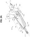
- FIG. 3Ais a top perspective view of a portion of a flow channel geometry with arrows schematically depicting flow of sample fluid and focusing fluid in accordance with certain embodiments described herein.
- FIG. 3Bis a bottom perspective view of a portion of a flow channel geometry in accordance with the embodiment of FIG. 3A , with arrows schematically depicting flow of sample fluid and focusing fluid in accordance with certain embodiments described herein.
- FIG. 3Cis top view of a portion of a flow channel geometry in accordance with the embodiment of FIG. 3A .
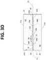
- FIG. 3Dis a cross-section through line 3 D- 3 D of FIG. 3C of a portion of a flow channel geometry in accordance with the embodiment of FIG. 3A
- FIG. 3Eis bottom view of a portion of a flow channel geometry in accordance with the embodiment of FIG. 3A .
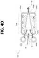
- FIG. 4Ais a top perspective view of a portion of a flow channel geometry with arrows schematically depicting flow of sample fluid and focusing fluid in accordance with certain embodiments described herein.
- FIG. 4Bis top view of a portion of a flow channel geometry in accordance with the embodiment of FIG. 4A .
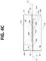
- FIG. 4Cis a cross-section through line 4 C- 4 C of FIG. 4B of a portion of a flow channel geometry in accordance with the embodiment of FIG. 4A .
- FIG. 4Dis bottom view of a portion of a flow channel geometry in accordance with the embodiment of FIG. 4A .
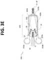
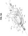
- FIG. 5Ais a top perspective view of a portion of a flow channel geometry with arrows schematically depicting flow of sample fluid and focusing fluid in accordance with certain embodiments described herein.
- FIG. 5Bis top view of a portion of a flow channel geometry in accordance with the embodiment of FIG. 5A .
- FIG. 5Cis a cross-section through line 5 C- 5 C of FIG. 5B of a portion of a flow channel geometry in accordance with the embodiment of FIG. 5A .
- FIG. 5Dis bottom view of a portion of a flow channel geometry in accordance with the embodiment of FIG. 5A .
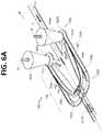
- FIG. 6Ais a top perspective view of a portion of a flow channel geometry with arrows schematically depicting flow of sample fluid and focusing fluid in accordance with certain embodiments described herein.
- FIG. 6Bis top view of a portion of a flow channel geometry in accordance with the embodiment of FIG. 6A .
- FIG. 6Cis a cross-section through line 6 C- 6 C of FIG. 6B of a portion of a flow channel geometry in accordance with the embodiment of FIG. 6A .
- FIG. 6Dis bottom view of a portion of a flow channel geometry in accordance with the embodiment of FIG. 6A .
- FIG. 7Ais top view of a portion of a substrate of the microfluidic chip, schematically illustrating micro channel geometry, in accordance with the embodiment of FIG. 5A , formed between an upper substrate layer and a lower substrate layer.
- FIG. 7Bis bottom view of a portion of an upper substrate layer in accordance with the embodiment of FIGS. 5A and 7A , schematically illustrating the micro channel geometry formed in the lower surface of the upper substrate layer.
- FIG. 7Cis top view of a portion of a lower substrate layer in accordance with the embodiment of FIGS. 5A and 7A , schematically illustrating the micro channel geometry formed in the upper surface of the lower substrate layer.
- a microfluidic particle (e.g., cell) analysis and/or sorting system for a microfluidic chipmay have a wide variety of applications as a therapeutic medical device enabling cell-based therapies, such as blood transfusion, bone marrow transplants, and/or mobilized peripheral blood implants.
- Embodiments of microfluidic sorting systemsmay be capable of selecting cells based on intrinsic characteristics as determined by interaction of light with the cells (e.g., scatter, reflection, and/or auto fluorescence) independent of protocols and necessary reagents.
- a microfluidic systemmay employ a closed, sterile, disposable cartridge including a microfluidic chip. The microfluidic system may process particles (e.g., cells) at high speeds, and deliver particles (e.g., cells) with high yield and high purity.
- Certain embodiments described hereinrelate systems and methods for producing a sheath flow in a flow channel and, in particular, in a micro channel in microfluidic devices.
- particlesincludes, but is not limited to, cells (e.g., blood platelets, white blood cells, tumorous cells, embryonic cells, spermatozoa, etc.), synthetic beads (e.g., polystyrene), organelles, and multi-cellular organisms.
- Particlesmay include liposomes, proteoliposomes, yeast, bacteria, viruses, pollens, algae, or the like.
- Particlesmay also refer to non-biological particles.
- particlesmay include metals, minerals, polymeric substances, glasses, ceramics, composites, or the like.
- particlesmay include cells, genetic material, RNA, DNA, fragments, proteins, etc. or bead, for example, with fluorochrome conjugated antibodies.
- microfluidic systemrefers to a system or device including at least one fluidic channel having microscale dimensions.
- the microfluidic systemmay be configured to handle, process, detect, analyze, eject, and/or sort a fluid sample and/or particles within a fluid sample.
- channelrefers to a pathway formed in or through a medium that allows for movement of fluids, such as liquids and gases.
- micro channelrefers to a channel, preferably formed in a microfluidic system or device, having cross-sectional dimensions in the range between about 1.0 ⁇ m and about 2000 ⁇ m, preferably between about 25 ⁇ m and about 500 ⁇ m, and most preferably between about 50 ⁇ m and about 300 ⁇ m.
- One of ordinary skill in the artwill be able to determine an appropriate volume and length of the micro channel for the desired application.
- the ranges aboveare intended to include the above-recited values as upper or lower limits.
- the micro channelmay have any selected cross-sectional shape or arrangement, non-limiting examples of which include a linear or non-linear configuration, a U-shaped or D-shaped configuration, and/or a rectangular, triangular, elliptical/oval, circular, square, or trapezoidal geometry.
- a microfluidic device or microfluidic chipmay include any suitable number of micro channels for transporting fluids.
- a microfluidic chipmay be provided as a disposable cartridge with a closed channel system.
- a particle processing system 200may be configured, dimensioned and adapted for analyzing, sorting, and/or processing (e.g., purifying, measuring, isolating, detecting, monitoring and/or enriching) particles (e.g., cells, microscopic particles, etc.) or the like.
- system 200may be a cytometer and/or a cell purification system or the like, although the present disclosure is not limited thereto. Rather, system 200 may take a variety of forms, and it is noted that the systems and methods described may be applied to other particle processing systems.
- system 200is a microfluidic flow sorter particle processing system (e.g., microfluidic chip based system) or the like.
- microfluidic flow sorter particle processing systeme.g., microfluidic chip based system
- Exemplary microfluidic flow sorter particle processing systems and components or the likeare disclosed, for example, in U.S. Pat. No. 8,529,161 (Ser. No. 13/179,084); U.S. Pat. No. 8,277,764 (Ser. No. 11/295,183); U.S. Pat. No. 8,123,044 (Ser. No. 11/800,469); U.S. Pat. No. 7,569,788 (Ser. No. 11/101,038); U.S. Pat. No. 7,492,522 (Ser. No.
- system 200may be a multi-channel or multi-jet flow sorter particle processing system (e.g., multiple capillaries or multiple fluid jet-based systems) or the like.
- exemplary multi-channel or multi-jet flow sorter particle processing systems and components or the likeare disclosed, for example, in US Patent Publication No. 2005/0112541 (Ser. No. 10/812,351), the entire contents of which is hereby incorporated by reference in its entirety.
- FIG. 1illustrates a system 200 suitable for implementing an illustrative embodiment of the present disclosure.
- System 200includes a microfluidic assembly 220 .
- Microfluidic assembly 220includes and/or is in communication with a particle inspection region and a sample fluid input region.
- Microfluidic assembly 220may include a plurality of micro channels for conveying a substance, such as particles or cells, therethrough.
- microfluidic assembly 220may be a combination of microfluidic chips, micro channels, cuvettes, capillaries, nozzles, or jets which may combine to produce a multichannel particle processing system.
- the micro channelstransport fluid and/or particles through the assembly 220 for processing, handling, and/or performing any suitable operation (e.g., on a liquid sample).
- Assembly 220may include any suitable number of micro channels for transporting fluids through assembly 220 .
- an optical detector system 226 for use with microfluidic assembly 220may be provided.
- Optical detector system 226may be configured for the interrogation of the particles flowing through or located within an interrogation region. Further, optical detector system 226 may monitor flow through a plurality of channels simultaneously. In exemplary embodiments, system 226 can inspect individual particles for one or more particular characteristics, such as size, form, fluorescence, optical scattering, as well as other characteristics.
- System 200also includes at least one electromagnetic radiation or light source 221 (e.g., a laser source or the like) for simultaneously or sequentially illuminating at least a portion of each of an interrogation region.
- the electromagnetic radiation source 221may be coupled to and/or in communication with beam shaping optics 225 (e.g., segmented mirror/mirrors or the like) for producing and forming a beam of electromagnetic radiation (e.g., light) 227 .
- the light source 221may be provide as one or more monochromatic light sources, polychromatic light sources, or any combination of the aforementioned.
- the electromagnetic radiation source(s) 221may have any suitable wavelength and one skilled in the art will recognize that any suitable light source(s) may be used.
- the one or more radiation beams 227may pass through an optical mask aligned with a plurality of particle-conveying micro channels in the microfluidic assembly 220 .
- the optical maskmay take the form of an array of pinholes (e.g., provided in an optically opaque layer) associated with the interrogation regions of the plurality of micro channels.
- Other spatial and/or spectral filter arraysmay be provided in the illumination and/or detection path of the particle processing system 200 .
- Optical extinctionrefers to the amount of electromagnetic radiation or light that a particle extinguishes, absorbs, or blocks.
- Angle dependent optical scatterrefers to the fraction of electromagnetic radiation that is scattered or bent at each angle away from or toward the incident electromagnetic radiation beam.
- Fluorescent electromagnetic radiationmay be electromagnetic radiation that is absorbed and/or scattered by molecules associated with a particle or cell and re-emitted at a different wavelength. In some instances, fluorescent detection may be performed using intrinsically fluorescent molecules.
- optical detector system 226may include one or more detector subsystems 230 to capture and observe the optical signals generated by the intersection of electromagnetic radiation beam 227 with a particle in a channel.
- Detector subsystems 230may include one or more extinction detector assemblies 231 for capturing extinction signals, one or more scatter detector assemblies 233 for capturing scatter signals, and one or more fluorescence detector assemblies 235 for capturing fluorescence signals.
- detector system 226may include at least one extinction detector assembly 231 , at least one scatter detector assembly 233 , and at least one fluorescence detector assembly 235 .
- Detector assemblies 231 , 233 , 235may include photomultipliers, photodiodes, cameras, or other suitable device(s).
- a detector subsystem 230may include one or more micro-lens systems 250 .
- a plurality of micro-lens systems 250may be provided as a micro-lens array 260 .
- detector subsystems 230may include fiber optics or other waveguide-type optical transmission elements to direct the signals to the sensor elements, one or more lenses, filters, mirrors, and/or other optical elements to collect, shape, transmit, etc. the signal exiting the interrogation region 222 and being received by the detector subsystems 230 .
- a single detector subsystem 230may be associated with a plurality of interrogation sites (e.g., microfluidic channels) and thus, may receive signals (simultaneously, sequentially, overlapping, non-overlapping, etc.) from each of the plurality of interrogation sites.
- the detector subsystems 230may be connected to electronics (not shown) to analyze the signals received from the detector assemblies and/or control one or more aspects of the particle sorting system 200 .
- microfluidic assembly 220may be configured as a microfluidic chip 20 and may include a substrate 21 having a plurality of channels 30 (e.g., micro channels) disposed or formed therein.
- the micro channels 30may be configured to transport fluid and/or particles through the microfluidic chip 20 for processing, handling, and/or performing any suitable operation on a liquid sample (e.g., a particle sorting system).
- a liquid samplee.g., a particle sorting system
- each micro channel 30may be a flow cytometer.
- the micro channels 30may be arranged parallel to each other.
- the microfluidic chip 20may include an input region 24 in which a sample containing particles (e.g., cells, etc.) is input into the microfluidic chip 20 for processing and an output region 26 for removing the processed sample from the microfluidic chip 20 .
- the substrate 21may be provided as a substantially planar substrate, i.e., having a first dimension (e.g., thickness t) much less than its other two dimensions (e.g., length L and width W). Further, the substrate 21 of the microfluidic chip 20 may include first and second major plane surfaces: an upper surface 21 a ; and a lower surface 21 b.
- the sample fluidmay be input via a sample inlet port 410 through the upper surface 21 a of the microfluidic chip 20 .
- Each micro channel 30may have an interrogation region 222 associated therewith. Particles in channels 30 may be detected while flowing through the interrogation regions 222 .
- individual particlesmay be inspected or measured for a particular characteristic, such as size, form, orientation, fluorescence intensity, etc. Interrogation regions 222 may be illuminated through the upper surface 21 a and/or the lower surface 21 b of the microfluidic chip 20 .
- the plurality of channels 30may be evenly distributed (i.e., evenly spaced) across the width W of the microfluidic chip 20 .
- a centerline-to-centerline spacing between the channels 30may range from 0.2 mm to 5.0 mm.
- the centerline-to-centerline spacing between the micro channels 30may be less than 4.0 mm, less than 3.0 mm, or even less than 1.0 mm.
- the centerline-to-centerline spacing between the micro channels 30may range from 2.5 mm to 3.0 mm.
- the centerline-to-centerline spacing between the micro channels 30may be less than 2.0 mm, less than 1.5 mm, or even less than 1.0 mm.
- the centerline-to-centerline spacing between the micro channels 30may range from 0.7 mm to 1.2 mm.
- the substrate 21 of the microfluidic chip 20may be formed with one or more substrate layers 60 . As shown in FIG. 2 , the substrate 21 may be formed by bonding or otherwise attaching an upper substrate layer 62 to a lower substrate layer 64 . In general, any number of layers may be used to form microfluidic chip 20 .
- the substrate layers 60 of the microfluidic chip 20may be glass (e.g., UV fused-silica, quartz, borofloat, etc.), PDMS, PMMA, COC, or any other suitably transmissive material.
- the thickness of the first substrate layer 62may range from approximately 100 ⁇ m up to approximately 1000 ⁇ m. In certain preferred embodiments, the thickness of substrate layer 62 may range from approximately 200 ⁇ m up to approximately 600 ⁇ m. For example, the thickness of substrate layer 62 may be approximately 400 ⁇ m. In other preferred embodiments, the thickness of substrate layer 62 may range from approximately 500 ⁇ m up to approximately 900 ⁇ m. By way of non-limiting examples, the thickness of substrate layer 62 may be approximately 700 ⁇ m or approximately 750 ⁇ m. In certain embodiments, the microfluidic chip 20 may be formed with only two substrate layers 62 , 64 .
- the microfluidic chip 20includes twenty-four micro channels 30 , although, in general, any number of micro channels 30 may be provided (e.g., as non-limiting examples, 2, 4, 8, 24, 36, 72, 144, or 288 channels). According to some embodiments, when microfluidic chip 20 has twenty-four micro channels 30 , the microfluidic chip 20 may have an overall width W ranging from 70 mm to 80 mm.
- each of the plurality of micro channels 30may include a sorting or diverting mechanism 28 for directing particles flowing within the channels 30 into various downstream channels.
- Sorting and/or divertingmay be accomplished through one or more mechanisms, which may include but are not limited to: mechanical displacement of the particle by deflecting a membrane with a piezoelectric actuator, thermal actuators, optical force techniques, dielectric methods (e.g., dielectrophoretic), ultrasonic transducers 27 (both bulk and/or surface), surface acoustic wave actuators, and other suitable sort mechanisms or techniques.
- a surface acoustic wave actuatormay be provided as an interdigitated transducer (IDT).
- IDTinterdigitated transducer
- Exemplary ultrasonic transducersare disclosed, for example, in U.S. patent Ser. Nos. 12/631,059 and 13/818,146, the entire contents of which are hereby incorporated by reference in their entirety.
- the particle processing system 200may include a receptacle or holder (not shown) for removably receiving microfluidic chip 20 . Further, the particle processing system 200 may include one or more stages for positioning the microfluidic chip 20 relative to the optical detection system 226 . The stages may allow for movement (translation and/or rotation) of the microfluidic chip 20 .
- a microfluidic chip having a micro channel for processing a sample fluidis provided.
- the micro channel 30may be in fluid communication with one or more sample inlet ports 410 (see FIG. 2 ) configured to receive a sample fluid S.
- the sample inlet ports 410may be in fluid communication with a sample reservoir, manifold, channel, well, test tube, etc.
- the micro channel 30may be in fluid communication with one or more focusing fluid inlet ports 450 (e.g., 450 a and 450 b ) configured to receive a focusing fluid SF.
- the focusing fluid inlet ports 450may be in fluid communication with a sheath fluid reservoir, manifold, channel, bag, bottle, container, etc.
- the micro channel 30may focus the sample by using focusing fluid (e.g., sheath fluid) and a core stream forming geometry 300 , for example, defined in the substrate 21 of the microfluidic chip 20 .
- the core stream forming geometry 300may be used to laminarly focus, streamline, decelerate, and/or accelerate the flow of the sample fluid S with a surrounding sheath of focusing fluid SF.
- the core stream forming geometry 300may include a lateral fluid focusing component (see, for example, lateral fluid focusing component 432 of the embodiment of FIGS. 3A-E ) and one or more vertical fluid focusing components (see, for example, vertical fluid focusing component 434 of FIGS. 3A-E ).
- lateralmay refer to a direction extending generally in the plane of the substantially planar microfluidic chip 20 and “vertical” may refer to a direction extending generally out of the plane of the microfluidic chip 20 .
- a sample fluid S flowing through the micro channel 30may enter the core stream forming geometry 400 along a longitudinal centerline CL (when viewed from above) of the core stream forming geometry 400 .
- Focusing fluid SFmay enter the core stream forming geometry 400 symmetrically with respect to the longitudinal centerline CL of the core stream forming geometry 400 .
- the focusing fluidmay enter the core stream forming geometry 400 at an upstream region 400 a of the core stream forming geometry and also at a downstream region of the core stream forming geometry 400 b .
- the sample fluid S and the focusing fluid SFmay be induced to flow through the micro channel 30 via any means known in the art, including one or more pumps (e.g., peristaltic pumps), ultrasonic drivers, etc.
- the core stream forming geometry 400may include a fluid focusing region 430 incorporated into a region of a flow channel 30 for generating a focused core stream flow wherein the focusing fluid SF shapes the sample stream S.
- the core stream forming geometry 400is illustrated as interior surfaces of a flow channel 30 in a microfluidic chip 20 , such as those microfluidic chips previously described.
- the illustrated core stream forming geometry 400provides improved sheath flow capabilities and thus improved sample focusing capabilities.
- the core stream forming geometry 400may be fabricated in plastics, polycarbonate, glass, metals, or other suitable materials using microfabrication, injection molding, stamping, machining, 3D printing or by other suitable fabrication techniques. As such, the core stream forming geometry 400 may be formed in a single substrate layer, or by a plurality of stacked layers.
- sheath inlets ports 450may be provided with conical inlet shapes that are each received at a sheath aggregating volume 422 .
- the sheath aggregating volumes 422may be provided with a single outlet or sheath fluid channel 442 , or multiple outlets or sheath fluid channels to further transport focusing fluid SF to flow channel 30 components.
- sheath inlet ports 450 a , 450 bare associated with a single micro channel 30 .
- Each sheath inlet port 450may provided with a single port outlet or sheath fluid channel 440 .
- Sheath fluid channel 440 ais illustrated as extending from sheath fluid inlet port 450 a and sheath fluid channel 440 b is illustrated as extending from sheath fluid inlet port 450 b .
- Each sheath fluid channel 440extends from an upstream region 430 a of the fluid focusing region 430 to a downstream region 430 b of the fluid focusing region 430 .
- Each sheath fluid channel 440is configured to transport focusing fluid SF from a sheath inlet port 450 to the micro channel 20 in the downstream region 430 b of the fluid focusing region 430 .
- the core stream forming geometry 400is symmetrically formed relative to a longitudinal centerline CL of the micro channel 30 (when viewed from above).
- a single sheath fluid inlet port 450may be provided and a branched sheath fluid channel may be configured transport focusing fluid form the single sheath fluid inlet port 450 to a plurality of regions of the core stream forming geometry 400 . Additionally, flow restrictions may be placed on one or more fluidic paths emanating from the sheath aggregating volume 422 .
- the fluid focusing region 430may include a lateral fluid focusing component 432 and a vertical fluid focusing component 434 , both of which may contribute to shaping the sample stream S and increasing the axial acceleration of both the focusing or sheath fluid FS and sample S through the flow channel 30 .
- the lateral fluid focusing componentmay include a lateral fluid focusing chamber 420 .
- the lateral fluid focusing chamber 420is provided with sample fluid S from a portion of the micro channel 30 in fluid communication with the sample inlet port 410 . Further, the lateral fluid focusing chamber 420 is provided with sheath or focusing fluid SF from the one or more sheath fluid inlet ports 450 .
- the lateral fluid focusing chamber 420is widest at its upstream end 420 a and narrowest at its downstream end 420 b .
- the chamber 420substantially linearly tapers symmetrically with respect to the centerline CL in the lateral direction.
- the chamber 420has a substantially constant thickness.
- the upstream end 420 ais provided as a substantially flat wall having two openings, one at each corner, for admitting focusing fluid SF.
- two sheath inlet ports 450 a , 450 bmay symmetrically introduce focusing fluid SF into the lateral fluid focusing chamber 420 .
- a relatively short channel 442 aextends between the sheath aggregating volume 422 a and the corner opening of the lateral fluid focusing chamber 420 .
- a relatively short channel 442 bextends between the sheath aggregating volume 422 b and laterally opposed corner opening of the lateral fluid focusing chamber 420 .
- focusing fluid SFenters chamber 420 from opposed lateral edges (or lateral sides) of the upstream end 420 a of focusing chamber 420 .
- a sample inlet portion 32 of the micro channel 30 transporting sample fluid Sextends beneath the plane of the lateral fluid focusing chamber 420 .
- the sample inlet portion 32 of micro channel 30is centered along the longitudinal centerline CL.
- the sample Sis injected into the plane of the focusing chamber 42 through the opening where the sample inlet portion 32 of the micro channel 30 and the lateral fluid focusing chamber 420 overlap OL.
- the length of the overlap OLis approximately a third of the length of the focusing chamber 420 .
- sample inlet portion 32 and the lateral fluid focusing chamber 420share a common opening (where otherwise they would have shared a common wall).
- Sample fluid Senters focusing chamber 420 from below via a symmetrically centered opening having a length equal to the overlap OL region and a width equal to the width of micro channel 30 .
- the sample stream Sjogs from the plane of the upstream micro channel 30 upward into the focusing fluid SF within the plane of the focusing chamber as it is introduced into the focusing chamber.
- the lateral dimension of the chamber 420decreases.
- an increasing inward force from the lateral sides of the chamber 420acts on the fluid within the chamber, thus tending to focus (e.g., constrict) the sample S in the middle of the lateral fluid focusing chamber 420 .
- the increasing inward forcefurther tends to accelerate both the sheath and the sample within the fluid focusing region 430 in the flow channel 30 .
- the vertical fluid focusing componentprovides a vertical upwardly-directed focusing force.
- vertical fluid focusing channels 440 a , 440 bintroduce focusing fluid FS from inlet ports 450 a , 450 b into the lateral fluid focusing chamber 420 at the downstream end 420 b .
- the vertical fluid focusing channels 440 a , 440 bextend under channel 30 .
- channel 440 aintersects the lower surface 30 b of channel 30 an opening or aperture forms a vertical focusing flow inlet 446 so that focusing fluid FS from channels 440 a , 440 b may enter channel 30 .
- the vertical fluid focusing channels 440 a , 440 bintroduce focusing fluid FS into fluid focusing chamber 420 at vertical focusing flow inlet 446 from below.
- the vertical fluid focusing channels 440 a , 440 bmay comprise a U-shaped or looping channel that branches away from the lateral fluid focusing chamber 420 and is provided in fluid communication at aperture region 446 with the lateral fluid focusing chamber 420 further downstream.
- the vertical fluid focusing channels 440may provide a means for diverting a portion of sheath fluid that may then be reintroduced into the flow channel 30 at a later point to focus the vertical position of the core stream of sample S.
- the sample Senters the fluid focusing region 430 at the upstream end 430 a in a plane P1 (see FIG. 3D ) below the plane P2 (see FIG. 3D ) in which the lateral fluid focusing chamber 420 is located.
- the sample Sis directed upward from plane P1 into the plane P2 of the lateral focusing chamber 420 in the overlapped region OL.
- the laterally focused sample within a sheath of focusing fluid(S+SF) is vertically focused upward by the introduction of focusing fluid SF at the vertical focusing flow inlet 446 from below.
- the focused streamexits the fluid focusing region 430 in the P2 (see FIG. 3D ) plane.
- FIG. 3Cis a top view of the core stream forming geometry 400 , including fluid focusing region 430 and lateral fluid focusing component 420 .
- a sample flow Sis illustrated entering the lateral focusing chamber 420 from the micro channel 30 .
- Focusing fluid flow SFis illustrated entering the lateral fluid focusing chamber 420 from each sheath inlet port 450 at the upstream region 420 b of the lateral fluid focusing chamber 420 . Further, the focusing fluid SF is introduced into the lateral fluid focusing chamber 420 from a lateral edge. In this particular embodiment, the focusing fluid SF is introduced into the lateral fluid focusing chamber 420 at a lateral, upstream corner of the fluid focusing chamber 420 .
- the width of the lateral fluid focusing chamber 420decreases in a downstream direction. In this particular embodiment, the width decreases linearly over a majority of the fluid focusing region 430 .
- the sheath flow SFprovides an increasing shearing force on the sample S, both accelerating the flow of the sample S, spacing out particles in the sample, and laterally focusing the sample flow into the center of the lateral fluid focusing chamber 420 .
- FIG. 3Drepresents a vertical cross-section along a longitudinal axis of the core stream forming geometry 400 .
- a first downwards vertical influence on the sample streamis created upon entry into the lateral fluid focusing chamber 420 , because the sample is introduced from under the lateral fluid focusing region 420 , so that its upward flow will be resisted by the sheath flow SF above it.
- a sample flow Senters the core stream forming geometry region via micro channel 30 and via sample inlet portion 32 .
- the sample Sreaches the end of the overlapped sample inlet region OL and moves upwards against a sheath flow SF in the plane of the lateral fluid focusing chamber 420 .
- the vertical fluid focusing channels 440 a , 440 bintroduce focusing fluid SF upward, thereby directing the sample S upwards and focusing the sample S away from the bottom of the flow channel 30 .
- FIG. 3Ddemonstrates two notably advantageous concepts.
- the representative sample flow Sreflects a non-perpendicular injection point of the sample S, e.g., via the sample inlet portion 32 .
- the sample inlet portion 32 of the micro channel 30may be configured to introduce the sample S in substantially a same flow direction (longitudinally) as the focusing fluid SF.
- multiple sheath fluid inlets for introducing focusing fluid SF into fluid focusing region 430may be provided.
- vertical fluid focusing channels 440 a , 440 bmay introduce focusing fluid SF at a vertical focusing flow inlet 446 .
- the core stream forming geometry 400accelerates and focuses the sample S and the sheath fluid SF around the centrally introduced sample S.
- the fluid focusing region 430focuses the sample S away from the sides of the micro channel.
- the vertically focusing component, joining the micro channel 30 downstream of the fluid focusing region 430provides additional focusing of the sample S within the focusing fluid SF.
- this secondary focusingfocuses the sample in a vertical direction from below the sample S.
- the combination of the lateral focusing and the vertical focusingprovides three-dimensional focusing of the sheath fluid around the sample.
- the resulting flowis hydrodynamically focused on all sides of the sample S away from the walls of the flow channel 30 , with the sample S being suspended as a focused core in the approximate center of the channel 30 .
- the sampleAfter being focused in the focusing region 430 , the sample may continue through an inspection region and a particle diverting and/or sorting region. Further, the particles may be aligned and/or oriented according to specific features in the following description and a sort action may be performed according to various mechanisms.
- FIGS. 4A-4D, 5A-5D and 6A-6Dintroduce various embodiments which include additional focusing regions, e.g., tertiary focusing regions, downstream of the secondary focusing regions.
- additional focusing regionse.g., tertiary focusing regions
- Fluid focusing region 530includes a vertical fluid focusing component 534 configured as a double horseshoe or double loop an including first and second sets of vertical fluid focusing channels 540 , 550 .
- This embodimentrelates to a core stream forming geometry 500 having a first pair of vertical fluid focusing channel 540 a , 540 b and second pair of vertical fluid focusing channel 550 a , 550 b configured to introduce opposing vertical fluid focusing sheath flows into lateral fluid focusing chamber 520 for an improved core stream formation.
- the first pair of vertical fluid focusing channel 540 a , 540 bintroduces focusing fluid SF into the downstream end 520 b of fluid focusing chamber 520 at vertical focusing flow inlet 548 (see FIG. 4C ) from above.
- the second pair of vertical fluid focusing channel 550 a , 550 bintroduces focusing fluid SF into the downstream end 520 b of fluid focusing chamber 520 at vertical focusing flow inlet 546 (see FIG. 4C ) from below.
- Vertical focusing flow inlet 548is located upstream of vertical focusing flow inlet 546 . Thus, after being laterally focused, the stream is vertically focused downward and then vertically focused upward.
- FIGS. 4A and 4Cshow that a sample inlet 52 (see FIG. 4A ) of the micro channel 30 is positioned at the same vertical plane as the lateral fluid focusing chamber 520 . Further, the lateral fluid focusing chamber 520 , the vertical fluid focusing channels 550 a , 550 b , and the sample inlet 52 all lie in the same plane, plane P1 (see FIG. 4C ). Additionally, vertical fluid focusing channels 540 a , 540 b lie in a plane P2 (see FIG. 4C ) above plane P1 (see FIG. 4C ).
- the vertical focusing channels 540 a , 540 b and the vertical focusing channels 550 a , 550 bintroduce opposing vertical focusing forces (via vertical focusing flow inlets 548 , 546 , respectively) that act on the sample S.
- the focused streamexits the fluid focusing region 530 in the P2 plane.
- a more focused and/or aligned sample core streammay result.
- fluid focusing region 530includes a lateral fluid focusing component 532 which includes lateral fluid focusing chamber 520 .
- the lateral fluid focusing chamber 520is widest at its upstream end 520 a and narrowest at its downstream end 520 b .
- the chamber 520substantially linearly tapers symmetrically with respect to the centerline CL in the lateral direction.
- the chamber 520has a substantially constant thickness.
- the upstream end 520 ais provided as a substantially flat wall having two openings, one at each corner, for admitting focusing fluid SF.
- two sheath inlet ports 450 a , 450 bmay symmetrically introduce focusing fluid SF into the lateral fluid focusing chamber 520 .
- a relatively short channel 542 aextends between the sheath aggregating volume 422 a and the corner opening of the lateral fluid focusing chamber 520 .
- a relatively short channel 542 bextends between the sheath aggregating volume 422 b and laterally opposed corner opening of the lateral fluid focusing chamber 520 .
- focusing fluid SFenters chamber 520 from opposed lateral edges (or lateral sides) of the upstream end 520 a of focusing chamber 520 .
- sample fluid Sdirectly flows into the chamber 520 , in the same plane P1 in which the chamber 520 is located, via a sample inlet 52 (see FIG. 4A ) of the micro channel 30 .
- focusing fluid SFflows into lateral fluid focusing chamber 520 from sheath inlet ports 450 .
- the focusing fluid SF from each inlet port 450may be divided into three sheath flow portions.
- a first focusing fluid portionmay enter the lateral fluid focusing chamber 520 at its upstream corners.
- the focusing fluid SFtends to focus the sample S in the center of the lateral fluid focusing channel 520 .
- a second focusing fluid portion from each inlet port 450may be diverted through a vertical fluid focusing channel 550 a (or 550 b ) and a third focusing fluid portion may be directed through a vertical fluid focusing channel 540 a (or 540 b ).
- the sheath aggregating volume 522may advantageously provide a greater cross sectional area than the end of the conical sheath inlet 450 , thus providing a beneficial volume for distributing focusing fluid at relatively high sheath flow rates through each of the sheath flow portions.
- the length the vertical focusing channels 540 a , 540 bis less than the length of vertical focusing channels 550 a , 550 b .
- the shorter length of vertical focusing channels 540 a , 540 bmeans that these channels have less resistance to flow of the focusing fluid therethrough (as compared to the vertical focusing channels 550 a , 550 b ).
- the volume of focusing fluid that may be introduced into the fluid focusing region 530 at vertical focusing flow inlet 548may be greater than the volume of focusing fluid that may be introduced into the fluid focusing region 530 at vertical focusing flow inlet 546 .
- the relative lengths of the vertical focusing channels 540 , 550may be modified in order control the vertical focusing of the stream.
- a difference in the focusing fluid flow through the first set of vertical focusing channels 540 and the second set of vertical focusing channels 550may provide for an improved ability to focus the vertical position of a core stream in a flow channel 30 .
- FIG. 4Ca vertical cross-section along a longitudinal axis of the core stream forming geometry 500 illustrates a core stream of sample S and a focusing fluid SF introduced into the flow channel 30 at substantially the same vertical position.
- Focusing fluid SF from the first set of vertical fluid focusing channels 540provides a downward focusing influence on the core stream of sample S, followed by an upward focusing influence from sheath fluid provided from the second set of vertical fluid focusing channels 550 .
- the portion of the flow channel 30 following the opposing vertical sheath flowsis at an elevated vertical position relative to the lateral fluid focusing chamber 520 and the sample inlet 52 .
- the portion of the flow channel 30 following the focusing regionmay be further manipulated in a region designed to impart orientation to particles in the core stream of sample.
- FIGS. 5A-5Dillustrate an alternative embodiment of the core stream forming geometry 600 having substantially the same vertical cross section as the embodiment of FIGS. 4A-4D (compare FIG. 4C with FIG. 4C ).
- sheath fluidpasses through from each sheath aggregating volume 422 into a tapered focused inlet 632 which immediately puts the focusing fluid into a trajectory for laterally focusing the core stream of sample fluid S.
- the tapered inlets 621 a , 621 bmay eliminate any fluid dead zone which may be caused by blunt entry geometries.
- the tapered inlets 621advantageously are configured to allow the focusing fluid SF to travel in an expanding inlet channel that so that the focusing fluid is travelling substantially parallel (or at a slight angle) to the sample fluid S flowing in the micro channel 30 immediately prior to the tapered inlets 621 merging with the channel 30 .
- This anglemay be less than 45 degrees from the longitudinal axis of the micro channel 30 . In preferred embodiments, this angle may be less than 30 degrees, less than 25 degrees, and even less than 20 degrees.
- the inlets 621may expand to the point of merger with the micro channel 30 .
- the configuration of the inlets 621provides a focusing fluid flow trajectory that may be substantially aligned with the sample fluid flow.
- enabling the focusing fluid SF to expand and travel substantially parallel to the sample S prior to mergingallows a laminar flow region to be established where all of the fluid is travelling in parallel as the fluids are merged.
- This streamlined mergingmay provide a substantial reduction in fluid mixing and turbulence at the point of merger.
- tapered inlets 621allow the lateral fluid focusing component 632 and the vertical fluid focusing component 634 to be somewhat isolated from each other.
- the upstream end of the vertical fluid focusing componentis upstream of where sample S enters the fluid focusing chamber 620 , thus mitigating any potential for sample S to inadvertently flow in the vertical fluid focusing component 634 .
- the lateral fluid focusing chamber 620has slightly convexly curved lateral edges.
- each of the first set of vertical fluid focusing channels 640 and the second vertical fluid focusing channels 650are also streamlined with a common inlet 655 .
- the cross-sectional areas of the vertical focusing channels 650 , 640need not be constant along their length, but may vary from one portion to another.
- the cross-sectional area of vertical fluid focusing channels 640may be larger than the flatter cross-section area of vertical fluid focusing channels 650 . This larger cross-sectional area of vertical fluid focusing channels 640 relative to the flatter cross section of vertical fluid focusing channels 650 may allow a greater flow of vertical focusing fluid to enter chamber 620 at vertical focusing flow inlet 648 (see FIG. 5C ) than at vertical focusing flow inlet 646 (see FIG. 5C ).
- the greater cross-sectional area and the shorter length of vertical focusing channels 640 a , 640 bmean that these channels have less resistance to flow of the focusing fluid therethrough (as compared to the vertical focusing channels 650 a , 650 b ).
- the volume of focusing fluid that may be introduced into the fluid focusing region 630 at vertical focusing flow inlet 648may be greater than the volume of focusing fluid that may be introduced into the fluid focusing region 630 at vertical focusing flow inlet 646 .
- the relative cross-sectional areas and/or the relative lengths of the vertical focusing channels 640 , 650may be modified in order control the vertical focusing of the stream.
- providing varying lengths, cross-sectional areas and/or non-constant cross-sectional areas for the different vertical fluid focusing channelsmay allow the vertical focusing forces to be balanced.
- aspects disclosed hereinallow the designer to tailor the focusing flows acting on the stream so as to optimize the position and/or shape of the focused stream within the channel.
- FIGS. 6A-6Dillustrate another embodiment of the core stream forming geometry 700 . Similar to the embodiment of FIGS. 5A-5D and as best shown in FIG. 6A , this embodiment also has streamlined fluid focusing flow components, such as a dedicated tapered inlet 721 extending into the lateral fluid focusing chamber 720 from the inlet port 450 and a common focusing fluid channel 755 connected directly to the sheath aggregating volume 422 of each sheath inlet 450 and supplying focusing fluid SF to the first and second sets of vertical fluid focusing channels 740 , 750 . Additionally, FIGS. 6A-6D illustrate an alternative vertical placement of some portions of each of the first vertical fluid focusing channel 740 and the second vertical fluid focusing channel 750 .
- streamlined fluid focusing flow componentssuch as a dedicated tapered inlet 721 extending into the lateral fluid focusing chamber 720 from the inlet port 450 and a common focusing fluid channel 755 connected directly to the sheath aggregating volume 422 of each sheath in
- the embodiment of FIGS. 6A-6Dare provided with a relatively large cross sectional areas of both the first set of vertical fluid focusing channels 740 and the second set of vertical fluid focusing channels 750 .
- This greater cross-sectional areaprovides less resistance to the focusing fluid entering the vertical fluid focusing component 734 relative to the focusing fluid enter the lateral fluid focusing component 732 .
- another way to balance and/or control the focusing forces acting on the sample Sis provided by controlling the relative fluidic resistances of the focusing fluid flow into the vertical fluid focusing component 734 and into the lateral fluid focusing component 732 .
- FIGS. 6A-6Dare provided with an enhanced sheath aggregating volume 422 in other to accommodate the relatively large cross sectional areas of both the first set of vertical fluid focusing channels 740 and the second set of vertical fluid focusing channels 750 .
- the vertical fluid focusing channels 740 , 750are configured with a reduced downstream cross-sectional area (as compared to the greater cross-sectional area provided in the upstream portion of the channels).
- substrate 21may be formed by bonding or otherwise attaching an upper substrate layer 62 to a lower substrate layer 64 .
- FIG. 7Aa top view of the substrate 21 is shown with the core stream forming geometry 300 visible through the top layer of the substrate.
- FIG. 7Ba lower surface 62 b of the upper substrate 62 of the substrate of FIG. 7A is shown. Portions of the fluid focusing components 300 ′ of the core stream forming geometry 300 are shown provided in the lower surface 62 b .
- FIG. 7Ba lower surface 62 b of the upper substrate 62 of the substrate of FIG. 7A is shown.
- Complementary portions of the fluid focusing components 300 ′′ core stream forming geometry 300are shown provided in the lower surface 62 b .
- FIG. 7Can upper surface 64 a of the lower substrate 64 of the substrate of FIG. 7 A is shown. Portions of the fluid focusing components are shown provided in the upper surface 64 a .
- the portions of the fluid focusing components 300 ′, 300 ′′ provided in these substrate layer surfacesmay be provided (via additive or subtractive manufacturing).
- a complicated core stream forming geometry 300such as the exemplary core stream forming geometries described herein, may be simply and efficiently provided with just two substrate layers. While the core stream forming geometry 300 depicted in the embodiment in FIGS. 7A-C is illustrated as the exemplary core stream forming geometry 600 of the embodiment of FIGS. 5A-D , it is appreciated that an upper substrate layer 62 and a lower substrate layer 64 may similarly be used to define any number of different stream forming geometries including, for example, any of the exemplary stream forming geometries 400 , 500 , 600 and 700 described herein, for example, with respect to the embodiments of FIGS. 3A-E , 4 A-D, 5 A-D and 6 A-D.
- features described for focusing a core streammay be combined with various features for monitoring, detecting, analyzing, and/or sorting particles of interest. See, e.g., U.S. Pat. Nos. 6,877,528, 6,808,075, and 7,298,478, which are hereby incorporated by reference in their entireties.
- the term “a” or “an” entityrefers to one or more of that entity.
- the terms “a” or “an”, “one or more” and “at least one”can be used interchangeably herein.
Landscapes
- Chemical & Material Sciences (AREA)
- Engineering & Computer Science (AREA)
- Health & Medical Sciences (AREA)
- Dispersion Chemistry (AREA)
- Analytical Chemistry (AREA)
- General Health & Medical Sciences (AREA)
- General Engineering & Computer Science (AREA)
- Mechanical Engineering (AREA)
- Chemical Kinetics & Catalysis (AREA)
- Pathology (AREA)
- Immunology (AREA)
- General Physics & Mathematics (AREA)
- Biochemistry (AREA)
- Life Sciences & Earth Sciences (AREA)
- Physics & Mathematics (AREA)
- Public Health (AREA)
- Water Supply & Treatment (AREA)
- Hematology (AREA)
- Clinical Laboratory Science (AREA)
- Automatic Analysis And Handling Materials Therefor (AREA)
- Physical Or Chemical Processes And Apparatus (AREA)
Abstract
Description
Claims (23)
Priority Applications (4)
| Application Number | Priority Date | Filing Date | Title |
|---|---|---|---|
| US14/213,800US10583439B2 (en) | 2013-03-14 | 2014-03-14 | Hydrodynamic focusing apparatus and methods |
| US16/813,255US11446665B2 (en) | 2013-03-14 | 2020-03-09 | Hydrodynamic focusing apparatus and methods |
| US17/944,867US12172163B2 (en) | 2013-03-14 | 2022-09-14 | Hydrodynamic focusing apparatus and methods |
| US18/953,925US20250144631A1 (en) | 2013-03-14 | 2024-11-20 | Hydrodynamic focusing apparatus and methods |
Applications Claiming Priority (2)
| Application Number | Priority Date | Filing Date | Title |
|---|---|---|---|
| US201361785734P | 2013-03-14 | 2013-03-14 | |
| US14/213,800US10583439B2 (en) | 2013-03-14 | 2014-03-14 | Hydrodynamic focusing apparatus and methods |
Related Child Applications (1)
| Application Number | Title | Priority Date | Filing Date |
|---|---|---|---|
| US16/813,255ContinuationUS11446665B2 (en) | 2013-03-14 | 2020-03-09 | Hydrodynamic focusing apparatus and methods |
Publications (2)
| Publication Number | Publication Date |
|---|---|
| US20140318645A1 US20140318645A1 (en) | 2014-10-30 |
| US10583439B2true US10583439B2 (en) | 2020-03-10 |
Family
ID=50686172
Family Applications (4)
| Application Number | Title | Priority Date | Filing Date |
|---|---|---|---|
| US14/213,800Active2036-01-16US10583439B2 (en) | 2013-03-14 | 2014-03-14 | Hydrodynamic focusing apparatus and methods |
| US16/813,255ActiveUS11446665B2 (en) | 2013-03-14 | 2020-03-09 | Hydrodynamic focusing apparatus and methods |
| US17/944,867ActiveUS12172163B2 (en) | 2013-03-14 | 2022-09-14 | Hydrodynamic focusing apparatus and methods |
| US18/953,925PendingUS20250144631A1 (en) | 2013-03-14 | 2024-11-20 | Hydrodynamic focusing apparatus and methods |
Family Applications After (3)
| Application Number | Title | Priority Date | Filing Date |
|---|---|---|---|
| US16/813,255ActiveUS11446665B2 (en) | 2013-03-14 | 2020-03-09 | Hydrodynamic focusing apparatus and methods |
| US17/944,867ActiveUS12172163B2 (en) | 2013-03-14 | 2022-09-14 | Hydrodynamic focusing apparatus and methods |
| US18/953,925PendingUS20250144631A1 (en) | 2013-03-14 | 2024-11-20 | Hydrodynamic focusing apparatus and methods |
Country Status (5)
| Country | Link |
|---|---|
| US (4) | US10583439B2 (en) |
| EP (2) | EP4220124A1 (en) |
| CN (1) | CN105283753B (en) |
| NZ (2) | NZ711384A (en) |
| WO (1) | WO2014153107A1 (en) |
Cited By (3)
| Publication number | Priority date | Publication date | Assignee | Title |
|---|---|---|---|---|
| US20200122937A1 (en)* | 2003-10-30 | 2020-04-23 | Cytonome/St, Llc | Multilayer hydrodynamic sheath flow structure |
| US11213824B2 (en) | 2017-03-29 | 2022-01-04 | The Research Foundation For The State University Of New York | Microfluidic device and methods |
| US11446665B2 (en)* | 2013-03-14 | 2022-09-20 | Cytonome/St, Llc | Hydrodynamic focusing apparatus and methods |
Families Citing this family (34)
| Publication number | Priority date | Publication date | Assignee | Title |
|---|---|---|---|---|
| US9943847B2 (en) | 2002-04-17 | 2018-04-17 | Cytonome/St, Llc | Microfluidic system including a bubble valve for regulating fluid flow through a microchannel |
| US11243494B2 (en) | 2002-07-31 | 2022-02-08 | Abs Global, Inc. | Multiple laminar flow-based particle and cellular separation with laser steering |
| US9260693B2 (en)* | 2004-12-03 | 2016-02-16 | Cytonome/St, Llc | Actuation of parallel microfluidic arrays |
| BRPI0518824B1 (en) | 2004-12-03 | 2017-11-28 | Cytonome/St, Llc | "PARTICLE CARTRIDGE FOR PARTICLE PROCESSING AND METHOD OF PROCESSING OF A SAMPLE" |
| US10908066B2 (en) | 2010-11-16 | 2021-02-02 | 1087 Systems, Inc. | Use of vibrational spectroscopy for microfluidic liquid measurement |
| CN105008895B (en)* | 2012-10-15 | 2019-02-15 | 纳诺赛莱克特生物医药股份有限公司 | System, apparatus and method for particle sorting |
| US10662408B2 (en) | 2013-03-14 | 2020-05-26 | Inguran, Llc | Methods for high throughput sperm sorting |
| US8961904B2 (en) | 2013-07-16 | 2015-02-24 | Premium Genetics (Uk) Ltd. | Microfluidic chip |
| US11796449B2 (en) | 2013-10-30 | 2023-10-24 | Abs Global, Inc. | Microfluidic system and method with focused energy apparatus |
| US10960396B2 (en) | 2014-05-16 | 2021-03-30 | Cytonome/St, Llc | Thermal activated microfluidic switching |
| JP2018509615A (en) | 2015-02-19 | 2018-04-05 | プレミアム ジェネティクス (ユーケー) リミテッド | Scanning infrared measurement system |
| JP6911021B2 (en)* | 2015-06-25 | 2021-07-28 | サイトノーム/エスティー・エルエルシー | Microfluidic devices and systems with acoustic manipulation |
| CN105149019B (en)* | 2015-06-29 | 2017-04-19 | 清华大学 | Micro-channel structure used for two-dimensional hydrodynamic focusing and microfluid chip |
| US9700891B2 (en) | 2015-11-13 | 2017-07-11 | International Business Machines Corporation | Integrated nanofluidic arrays for high capacity colloid separation |
| CN105854963B (en)* | 2016-04-06 | 2017-11-21 | 清华大学 | The micro-channel structure and micro-fluid chip of two dimensional fluid dynamic focus are realized using single channel sheath fluid |
| CN106769733B (en)* | 2017-01-10 | 2020-09-18 | 中国计量大学 | Ultrasonic focusing type river sediment concentration on-line measuring instrument |
| WO2018175411A1 (en) | 2017-03-20 | 2018-09-27 | Nanocellect Biomedical, Inc. | Systems, apparatuses, and methods for cell sorting and flow cytometry |
| CN106914288B (en)* | 2017-03-21 | 2019-01-29 | 武汉大学 | A kind of micro-fluidic high frequency sound focusing chip and preparation method thereof |
| JP2020534168A (en)* | 2017-09-21 | 2020-11-26 | エイエムピー・ロボティクス・コーポレーション | Systems and methods for robot suction grippers |
| CN107638836B (en)* | 2017-11-09 | 2023-10-03 | 东南大学 | Multiple emulsion preparation system |
| US20190283022A1 (en)* | 2018-03-15 | 2019-09-19 | Behrad Vahidi | Highly parallel microfluidic blood separation device |
| EP3796998A1 (en) | 2018-05-23 | 2021-03-31 | ABS Global, Inc. | Systems and methods for particle focusing in microchannels |
| CN109731621B (en) | 2019-01-02 | 2020-07-24 | 京东方科技集团股份有限公司 | Microfluidic substrate, preparation method thereof and microfluidic panel |
| US10962427B2 (en)* | 2019-01-10 | 2021-03-30 | Nextinput, Inc. | Slotted MEMS force sensor |
| CN113498362B (en)* | 2019-02-27 | 2023-01-20 | 京瓷株式会社 | Particle separation measuring device and particle separation measuring apparatus |
| EP4245140A3 (en) | 2019-04-18 | 2024-01-17 | ABS Global, Inc. | System and process for continuous addition of cryoprotectant |
| US10532357B1 (en)* | 2019-04-26 | 2020-01-14 | Genus Plc | Single-sheath microfluidic chip |
| CN110237873B (en)* | 2019-04-28 | 2024-05-07 | 杭州电子科技大学 | Sheath-flow-free micro-fluidic chip for particle separation based on surface acoustic wave |
| CN110343611B (en)* | 2019-08-14 | 2022-08-30 | 无锡研奥电子科技有限公司 | Micro-fluidic chip |
| US11628439B2 (en) | 2020-01-13 | 2023-04-18 | Abs Global, Inc. | Single-sheath microfluidic chip |
| JP7591575B2 (en)* | 2020-01-13 | 2024-11-28 | エイビーエス グローバル、インコーポレイテッド | Single-sheath microfluidic chip |
| CN115427783A (en)* | 2020-01-14 | 2022-12-02 | 福斯分析仪器公司 | hydrodynamic focusing device |
| EP4248190A4 (en) | 2020-11-23 | 2024-12-25 | ABS Global, Inc. | Modular flow cytometry systems and methods of processing samples |
| EP4484010A1 (en) | 2023-06-28 | 2025-01-01 | Instytut Chemii Fizycznej PAN | Microfluidic system with integrated single-mode optical fiber |
Citations (99)
| Publication number | Priority date | Publication date | Assignee | Title |
|---|---|---|---|---|
| US3649829A (en) | 1970-10-06 | 1972-03-14 | Atomic Energy Commission | Laminar flow cell |
| US4126425A (en) | 1977-06-15 | 1978-11-21 | Hatch Associates Ltd. | Gas mixer for sublimation purposes |
| US4503385A (en) | 1983-07-11 | 1985-03-05 | Becton, Dickinson And Company | Apparatus and method for regulating sheath fluid flow in a hydrodynamically focused fluid flow system |
| US4752131A (en) | 1984-04-04 | 1988-06-21 | Basf Aktiengesellschaft | Laser-optical arrangement for measuring the degree of dispersion in flowing systems |
| US4756427A (en) | 1984-09-11 | 1988-07-12 | Partec Ag | Method and apparatus for sorting particles |
| US4836039A (en) | 1986-09-12 | 1989-06-06 | Canadian Patents & Development Limited | Method and apparatus for introduction of a particulate sample for analysis |
| US4844610A (en) | 1988-04-29 | 1989-07-04 | Becton, Dickinson And Company | Backflow isolator and capture system |
| US4954715A (en) | 1989-06-26 | 1990-09-04 | Zoeld Tibor | Method and apparatus for an optimized multiparameter flow-through particle and cell analyzer |
| US4983038A (en) | 1987-04-08 | 1991-01-08 | Hitachi, Ltd. | Sheath flow type flow-cell device |
| US5021244A (en) | 1988-12-06 | 1991-06-04 | Cytogam, Inc. | Sex-associated membrane antibodies and their use for increasing the probability that offspring will be of a desired sex |
| US5030002A (en) | 1989-08-11 | 1991-07-09 | Becton, Dickinson And Company | Method and apparatus for sorting particles with a moving catcher tube |
| US5040890A (en) | 1987-11-25 | 1991-08-20 | Becton, Dickinson And Company | Sheathed particle flow controlled by differential pressure |
| US5135759A (en) | 1989-05-10 | 1992-08-04 | The United States Of America As Represented By The Secretary Of Agriculture | Method to preselect the sex of offspring |
| US5311290A (en) | 1992-09-30 | 1994-05-10 | Pulp And Paper Research Institute Of Canada | Imaging apparatus and method of fiber analysis |
| US5521079A (en) | 1994-01-24 | 1996-05-28 | The Regents Of The University Of California | Microcapsule generating system containing an air knife and method of encapsulating |
| US5808737A (en) | 1996-02-29 | 1998-09-15 | Sienna Biotech, Inc. | Pre-analysis chamber for a flow particle analyzer |
| WO1998043066A1 (en) | 1997-03-26 | 1998-10-01 | University Of Washington | Device and method for 3-dimensional alignment of particles in microfabricated flow channels |
| US5880835A (en) | 1992-02-18 | 1999-03-09 | Hitachi, Ltd. | Apparatus for investigating particles in a fluid, and a method of operation thereof |
| US5902745A (en) | 1995-09-22 | 1999-05-11 | Gore Hybrid Technologies, Inc. | Cell encapsulation device |
| WO1999060397A1 (en) | 1998-05-18 | 1999-11-25 | University Of Washington | Liquid analysis cartridge |
| US6053667A (en) | 1997-12-12 | 2000-04-25 | Mitsui High-Tec Inc. | Carrying apparatus for spherical objects |
| WO2000070080A1 (en) | 1999-05-17 | 2000-11-23 | Caliper Technologies Corp. | Focusing of microparticles in microfluidic systems |
| US6365106B1 (en) | 1999-01-21 | 2002-04-02 | Sysmex Corporation | Sheath flow cell and blood analyzer using the same |
| US20020097633A1 (en) | 2000-08-07 | 2002-07-25 | Nanostream,Inc. | Multi-stream microfluidic mixers |
| US20020149766A1 (en) | 2001-04-03 | 2002-10-17 | Ronald Bardell | Split focusing cytometer |
| US6473171B1 (en) | 1999-01-15 | 2002-10-29 | Coors Brewing Company | Biocompatible apparatus for ultrasensitive and rapid detection of contaminants in liquids |
| US6475364B1 (en) | 1999-02-02 | 2002-11-05 | Caliper Technologies Corp. | Methods, devices and systems for characterizing proteins |
| US6592821B1 (en) | 1999-05-17 | 2003-07-15 | Caliper Technologies Corp. | Focusing of microparticles in microfluidic systems |
| WO2003078972A1 (en) | 2002-03-14 | 2003-09-25 | Micronics, Inc. | Ribbon flow cytometry and cell sorting |
| US6663352B2 (en) | 2001-07-25 | 2003-12-16 | Itt Manufacturing Enterprises, Inc. | Method and apparatus for dynamically determining vapor pressure in pumping systems |
| US20040043506A1 (en)* | 2002-08-30 | 2004-03-04 | Horst Haussecker | Cascaded hydrodynamic focusing in microfluidic channels |
| US6710874B2 (en) | 2002-07-05 | 2004-03-23 | Rashid Mavliev | Method and apparatus for detecting individual particles in a flowable sample |
| US6749374B1 (en) | 1997-12-11 | 2004-06-15 | Ecotechnology, Ltd. | Flow development chamber for creating a vortex flow and a laminar flow |
| US20040120856A1 (en) | 2001-03-19 | 2004-06-24 | Per Andersson | Structural units that define fluidic functions |
| US20040169867A1 (en) | 2001-05-17 | 2004-09-02 | Dakocytomation Denmark A/S | Flow cytomer with active automated optical alignment system |
| US6808075B2 (en) | 2002-04-17 | 2004-10-26 | Cytonome, Inc. | Method and apparatus for sorting particles |
| WO2005022147A1 (en) | 2003-08-28 | 2005-03-10 | Celula, Inc. | Methods and apparatus for sorting cells using an optical switch in a microfluidic channel network |
| US6877528B2 (en) | 2002-04-17 | 2005-04-12 | Cytonome, Inc. | Microfluidic system including a bubble valve for regulating fluid flow through a microchannel |
| WO2005042137A2 (en) | 2003-10-30 | 2005-05-12 | Cytonome, Inc. | Multilayer hydrodynamic sheath flow structure |
| US20050112541A1 (en) | 2003-03-28 | 2005-05-26 | Monsanto Technology Llc | Apparatus, methods and processes for sorting particles and for providing sex-sorted animal sperm |
| US20060113190A1 (en) | 2002-12-27 | 2006-06-01 | Kurnik Ronald T | Microfluidic device and method for improved sample handling |
| US7105355B2 (en)* | 2001-07-18 | 2006-09-12 | The Regents Of The University Of Michigan | Flow cytometers and detection system of lesser size |
| US7116407B2 (en) | 1998-12-15 | 2006-10-03 | Union Biometrica, Inc. | System for axial pattern analysis of multicellular organisms |
| US7157274B2 (en) | 2002-06-24 | 2007-01-02 | Cytonome, Inc. | Method and apparatus for sorting particles |
| US20070014695A1 (en) | 2005-04-26 | 2007-01-18 | Applera Corporation | Systems and Methods for Multiple Analyte Detection |
| US7195920B2 (en) | 1997-12-31 | 2007-03-27 | Xy, Inc. | Collection systems for cytometer sorting of sperm |
| US7208265B1 (en) | 1999-11-24 | 2007-04-24 | Xy, Inc. | Method of cryopreserving selected sperm cells |
| US7242474B2 (en) | 2004-07-27 | 2007-07-10 | Cox James A | Cytometer having fluid core stream position control |
| US7298478B2 (en) | 2003-08-14 | 2007-11-20 | Cytonome, Inc. | Optical detector for a particle sorting system |
| US7355696B2 (en) | 2005-02-01 | 2008-04-08 | Arryx, Inc | Method and apparatus for sorting cells |
| US7402131B2 (en) | 2003-09-04 | 2008-07-22 | Arryx, Inc. | Multiple laminar flow-based particle and cellular separation with laser steering |
| US20080185057A1 (en) | 2005-05-02 | 2008-08-07 | Manu Prakash | Microfluidic Bubble Logic Devices |
| US7419784B2 (en) | 2002-04-02 | 2008-09-02 | Dubrow Robert S | Methods, systems and apparatus for separation and isolation of one or more sample components of a sample biological material |
| US7434982B2 (en) | 2003-05-30 | 2008-10-14 | Fujifilm Corporation | Micro mixing and reaction device |
| US7442339B2 (en) | 2004-03-31 | 2008-10-28 | Intel Corporation | Microfluidic apparatus, Raman spectroscopy systems, and methods for performing molecular reactions |
| US7452726B2 (en) | 2002-04-01 | 2008-11-18 | Fluidigm Corporation | Microfluidic particle-analysis systems |
| US20080311005A1 (en) | 2007-06-14 | 2008-12-18 | Samsung Electronics Co., Ltd. | Apparatus for focusing and detecting particles in sample and method of manufacturing the same |
| US20090116005A1 (en) | 2007-11-02 | 2009-05-07 | Motohiro Furuki | Fine particle measuring method, substrate for measurement, and measuring apparatus |
| US20090126516A1 (en) | 2006-03-09 | 2009-05-21 | Kazuki Yamamoto | Micro fluid device and trace liquid diluting method |
| US7553453B2 (en) | 2000-06-02 | 2009-06-30 | Honeywell International Inc. | Assay implementation in a microfluidic format |
| US20090178716A1 (en) | 2008-01-16 | 2009-07-16 | Acoustic Cytometry Systems, Inc. | System and Method for Acoustic Focusing Hardware and Implementations |
| US7569788B2 (en) | 2002-04-17 | 2009-08-04 | Cytonome/St, Llc | Method and apparatus for sorting particles |
| US20090201504A1 (en)* | 2005-08-09 | 2009-08-13 | Maxwell Sensors, Inc. | Hydrodynamic focusing for analyzing rectangular microbeads |
| US7638339B2 (en) | 2003-06-26 | 2009-12-29 | Intel Corporation | Hydrodynamic focusing devices |
| US7641856B2 (en) | 2004-05-14 | 2010-01-05 | Honeywell International Inc. | Portable sample analyzer with removable cartridge |
| US7751040B2 (en) | 2005-10-05 | 2010-07-06 | Digital Bio Technology Co., Ltd. | Microchip with expansion channel and flowcytometer using this microchip |
| US7772287B2 (en) | 2001-02-23 | 2010-08-10 | Japan Science & Technology Agency | Process and apparatus for producing emulsion and microcapsules |
| US7776268B2 (en) | 2005-10-13 | 2010-08-17 | Accuri Cytometers, Inc. | User interface for a fluidic system of a flow cytometer |
| US7802686B2 (en) | 2004-09-22 | 2010-09-28 | Fuji Xerox Co., Ltd. | Method and device for classifying fine particles |
| US7833421B2 (en) | 2005-10-25 | 2010-11-16 | Elmar Huymann | Degermination through cavitation |
| US7850907B2 (en) | 2003-06-26 | 2010-12-14 | Intel Corporation | Fabricating structures in micro-fluidic channels based on hydrodynamic focusing |
| US20110003303A1 (en) | 2009-06-10 | 2011-01-06 | Cynvenio Biosystems, Inc. | Sheath flow devices and methods |
| WO2011003073A1 (en) | 2009-07-02 | 2011-01-06 | Sony Corporation | System and method for the measurement of multiple emissions from multiple parallel flow channels in a flow cytometry system |
| US20110008817A1 (en) | 2009-07-08 | 2011-01-13 | Durack Gary P | Microfluidic device having a flow channel within a gain medium |
| US7993934B2 (en) | 2007-10-30 | 2011-08-09 | Fuji Xerox Co., Ltd. | Reaction method using a microreactor, and a microreactor |
| US20110196637A1 (en) | 2010-02-05 | 2011-08-11 | Cytonome/St, Llc | Particle processing systems and methods for normalization/calibration of same |
| US8123044B2 (en) | 2006-05-05 | 2012-02-28 | Cytonome/St, Llc | Actuation of parallel microfluidic arrays |
| WO2012027366A2 (en) | 2010-08-23 | 2012-03-01 | President And Fellows Of Harvard College | Acoustic waves in microfluidics |
| US20120097633A1 (en) | 2009-06-19 | 2012-04-26 | Presticorc | Anti-drip device for a bottle |
| US20120138152A1 (en) | 2010-12-02 | 2012-06-07 | Naval Research Laboratory | Tubular Array for Fluidic Focusing with Integrated Optical Access Region |
| US20120196314A1 (en) | 2007-09-10 | 2012-08-02 | The Penn State Research Foundation | Three-dimensional (3d) hydrodynamic focusing using a microfluidic device |
| US8277764B2 (en) | 2004-12-03 | 2012-10-02 | Cytonome/St, Llc | Unitary cartridge for particle processing |
| US20120277902A1 (en) | 2011-01-03 | 2012-11-01 | Cytonome/St, Llc | Method and Apparatus for Monitoring and Optimizing Microfluidic Particle Sorting |
| US8383043B2 (en) | 2004-05-14 | 2013-02-26 | Honeywell International Inc. | Analyzer system |
| US8426159B2 (en) | 2004-01-16 | 2013-04-23 | California Institute Of Technology | Microfluidic chemostat |
| US8487273B2 (en) | 2010-12-17 | 2013-07-16 | Sony Corporaiton | Microchip and particulate fractional collection apparatus |
| US8528427B2 (en) | 2010-10-29 | 2013-09-10 | Becton, Dickinson And Company | Dual feedback vacuum fluidics for a flow-type particle analyzer |
| US8573060B2 (en) | 2008-12-05 | 2013-11-05 | The Penn State Research Foundation | Particle focusing within a microfluidic device using surface acoustic waves |
| US20130334407A1 (en) | 2012-05-16 | 2013-12-19 | Cytonome/St, Llc | Large area, low f-number optical system |
| US20140027356A1 (en) | 2012-07-24 | 2014-01-30 | Sony Corporation | Microparticle sorting method |
| US20140085898A1 (en) | 2012-09-17 | 2014-03-27 | Cytonome/St, Llc | Focal plane shifting system |
| US8695618B2 (en) | 2010-12-22 | 2014-04-15 | Carnegie Mellon University | 3D chemical pattern control in 2D fluidics devices |
| US8808642B2 (en) | 2011-08-19 | 2014-08-19 | Logos Biosystems, Inc. | Microchip |
| US20140339445A1 (en) | 2013-03-14 | 2014-11-20 | Cytonome/St, Llc | Micro-lens systems for particle processing systems |
| WO2015009284A1 (en) | 2013-07-16 | 2015-01-22 | Premium Genetics (Uk) Ltd. | Microfluidic chip |
| US8961904B2 (en) | 2013-07-16 | 2015-02-24 | Premium Genetics (Uk) Ltd. | Microfluidic chip |
| US9486757B2 (en) | 2009-03-13 | 2016-11-08 | President And Fellows Of Harvard College | Scale-up of microfluidic devices |
| US9588100B2 (en) | 2013-10-30 | 2017-03-07 | Premium Genetics (Uk) Ltd | Microfluidic system and method with focused energy apparatus |
| US20170102381A1 (en) | 2004-10-12 | 2017-04-13 | President And Fellows Of Harvard College | Compartmentalised screening by microfluidic control |
Family Cites Families (26)
| Publication number | Priority date | Publication date | Assignee | Title |
|---|---|---|---|---|
| AU6541596A (en) | 1995-06-16 | 1997-01-15 | University Of Washington | Microfabricated differential extraction device and method |
| US11243494B2 (en) | 2002-07-31 | 2022-02-08 | Abs Global, Inc. | Multiple laminar flow-based particle and cellular separation with laser steering |
| US6825926B2 (en)* | 2002-11-19 | 2004-11-30 | International Remote Imaging Systems, Inc. | Flow cell for urinalysis diagnostic system and method of making same |
| US20050252840A1 (en) | 2004-05-13 | 2005-11-17 | Eksigent Technologies, Llc | Micromixer |
| US8398935B2 (en) | 2005-06-09 | 2013-03-19 | The United States Of America, As Represented By The Secretary Of The Navy | Sheath flow device and method |
| US7942568B1 (en) | 2005-06-17 | 2011-05-17 | Sandia Corporation | Active micromixer using surface acoustic wave streaming |
| US20110189714A1 (en)* | 2010-02-03 | 2011-08-04 | Ayliffe Harold E | Microfluidic cell sorter and method |
| US20090051372A1 (en) | 2006-10-30 | 2009-02-26 | Palaniappan Sethu | 3D fluid confined sample stream coulter flow cytometry |
| US7867778B2 (en) | 2007-02-23 | 2011-01-11 | Visiongate, Inc. | Fluid focusing for positional control of a specimen for 3-D imaging |
| US8273302B2 (en) | 2007-05-15 | 2012-09-25 | Panasonic Corporation | Component separation device |
| US20090001024A1 (en) | 2007-06-26 | 2009-01-01 | Porter Marc D | Using asymmetrical flow focusing to detect and enumerate magnetic particles in microscale flow systems with embedded magnetic-field sensors |
| JP4661942B2 (en) | 2008-05-13 | 2011-03-30 | ソニー株式会社 | Microchip and its channel structure |
| WO2009151624A1 (en)* | 2008-06-13 | 2009-12-17 | Xy, Inc. | Lubricious microfluidic flow path system |
| US8865003B2 (en) | 2008-09-26 | 2014-10-21 | Abbott Laboratories | Apparatus and method for separation of particles suspended in a liquid from the liquid in which they are suspended |
| JP2010151777A (en)* | 2008-11-19 | 2010-07-08 | Sony Corp | Microparticle analyzer, microchip, and method for analyzing microparticle |
| JP2010252785A (en) | 2009-03-31 | 2010-11-11 | Kanagawa Acad Of Sci & Technol | Cell concentration separator |
| US9625454B2 (en)* | 2009-09-04 | 2017-04-18 | The Research Foundation For The State University Of New York | Rapid and continuous analyte processing in droplet microfluidic devices |
| US10024819B2 (en)* | 2010-10-21 | 2018-07-17 | The Regents Of The University Of California | Microfluidics with wirelessly powered electronic circuits |
| US9821310B2 (en) | 2011-03-31 | 2017-11-21 | The University Of Akron | Two-stage microfluidic device for acoustic particle manipulation and methods of separation |
| US8727129B2 (en) | 2011-08-16 | 2014-05-20 | Lawrence Livermore National Security, Llc. | Microfluidic ultrasonic particle separators with engineered node locations and geometries |
| EP2864762A4 (en) | 2012-06-21 | 2016-01-20 | Stc Unm | SPATIALLY CORRELATED LIGHT COLLECTION FROM EXCITED MULTIPLE SAMPLING STREAMS USING A LIGHT SOURCE CONCENTRATED ON A LINE |
| CN105283753B (en)* | 2013-03-14 | 2020-07-10 | 塞通诺米/St有限责任公司 | Hydrodynamic focusing apparatus and method |
| CA2898740C (en)* | 2013-03-14 | 2018-09-11 | Inguran, Llc | Apparatus and methods for high throughput sperm sorting |
| US11796449B2 (en) | 2013-10-30 | 2023-10-24 | Abs Global, Inc. | Microfluidic system and method with focused energy apparatus |
| EP3108219B1 (en) | 2014-02-20 | 2020-04-01 | Malvern Panalytical Limited | Heterogeneous fluid sample characterization |
| CN107024744A (en) | 2016-01-29 | 2017-08-08 | 青岛海信宽带多媒体技术有限公司 | A kind of optical module and wavelength monitor method |
- 2014
- 2014-03-14CNCN201480028102.2Apatent/CN105283753B/enactiveActive
- 2014-03-14EPEP22214486.7Apatent/EP4220124A1/enactivePending
- 2014-03-14WOPCT/US2014/029090patent/WO2014153107A1/enactiveApplication Filing
- 2014-03-14NZNZ711384Apatent/NZ711384A/enunknown
- 2014-03-14EPEP14722885.2Apatent/EP2972212B1/enactiveActive
- 2014-03-14NZNZ743491Apatent/NZ743491A/enunknown
- 2014-03-14USUS14/213,800patent/US10583439B2/enactiveActive
- 2020
- 2020-03-09USUS16/813,255patent/US11446665B2/enactiveActive
- 2022
- 2022-09-14USUS17/944,867patent/US12172163B2/enactiveActive
- 2024
- 2024-11-20USUS18/953,925patent/US20250144631A1/enactivePending
Patent Citations (122)
| Publication number | Priority date | Publication date | Assignee | Title |
|---|---|---|---|---|
| US3649829A (en) | 1970-10-06 | 1972-03-14 | Atomic Energy Commission | Laminar flow cell |
| US4126425A (en) | 1977-06-15 | 1978-11-21 | Hatch Associates Ltd. | Gas mixer for sublimation purposes |
| US4503385A (en) | 1983-07-11 | 1985-03-05 | Becton, Dickinson And Company | Apparatus and method for regulating sheath fluid flow in a hydrodynamically focused fluid flow system |
| US4752131A (en) | 1984-04-04 | 1988-06-21 | Basf Aktiengesellschaft | Laser-optical arrangement for measuring the degree of dispersion in flowing systems |
| US4756427A (en) | 1984-09-11 | 1988-07-12 | Partec Ag | Method and apparatus for sorting particles |
| US4836039A (en) | 1986-09-12 | 1989-06-06 | Canadian Patents & Development Limited | Method and apparatus for introduction of a particulate sample for analysis |
| US4983038A (en) | 1987-04-08 | 1991-01-08 | Hitachi, Ltd. | Sheath flow type flow-cell device |
| US5040890A (en) | 1987-11-25 | 1991-08-20 | Becton, Dickinson And Company | Sheathed particle flow controlled by differential pressure |
| US4844610A (en) | 1988-04-29 | 1989-07-04 | Becton, Dickinson And Company | Backflow isolator and capture system |
| US5021244A (en) | 1988-12-06 | 1991-06-04 | Cytogam, Inc. | Sex-associated membrane antibodies and their use for increasing the probability that offspring will be of a desired sex |
| US5135759A (en) | 1989-05-10 | 1992-08-04 | The United States Of America As Represented By The Secretary Of Agriculture | Method to preselect the sex of offspring |
| US4954715A (en) | 1989-06-26 | 1990-09-04 | Zoeld Tibor | Method and apparatus for an optimized multiparameter flow-through particle and cell analyzer |
| US5030002A (en) | 1989-08-11 | 1991-07-09 | Becton, Dickinson And Company | Method and apparatus for sorting particles with a moving catcher tube |
| US5880835A (en) | 1992-02-18 | 1999-03-09 | Hitachi, Ltd. | Apparatus for investigating particles in a fluid, and a method of operation thereof |
| US5311290A (en) | 1992-09-30 | 1994-05-10 | Pulp And Paper Research Institute Of Canada | Imaging apparatus and method of fiber analysis |
| US5521079A (en) | 1994-01-24 | 1996-05-28 | The Regents Of The University Of California | Microcapsule generating system containing an air knife and method of encapsulating |
| US5902745A (en) | 1995-09-22 | 1999-05-11 | Gore Hybrid Technologies, Inc. | Cell encapsulation device |
| US5808737A (en) | 1996-02-29 | 1998-09-15 | Sienna Biotech, Inc. | Pre-analysis chamber for a flow particle analyzer |
| WO1998043066A1 (en) | 1997-03-26 | 1998-10-01 | University Of Washington | Device and method for 3-dimensional alignment of particles in microfabricated flow channels |
| US6159739A (en) | 1997-03-26 | 2000-12-12 | University Of Washington | Device and method for 3-dimensional alignment of particles in microfabricated flow channels |
| US6749374B1 (en) | 1997-12-11 | 2004-06-15 | Ecotechnology, Ltd. | Flow development chamber for creating a vortex flow and a laminar flow |
| US6053667A (en) | 1997-12-12 | 2000-04-25 | Mitsui High-Tec Inc. | Carrying apparatus for spherical objects |
| US7195920B2 (en) | 1997-12-31 | 2007-03-27 | Xy, Inc. | Collection systems for cytometer sorting of sperm |
| US6576194B1 (en) | 1998-05-18 | 2003-06-10 | University Of Washington | Sheath flow assembly |
| WO1999060397A1 (en) | 1998-05-18 | 1999-11-25 | University Of Washington | Liquid analysis cartridge |
| US6537501B1 (en) | 1998-05-18 | 2003-03-25 | University Of Washington | Disposable hematology cartridge |
| US7116407B2 (en) | 1998-12-15 | 2006-10-03 | Union Biometrica, Inc. | System for axial pattern analysis of multicellular organisms |
| US6473171B1 (en) | 1999-01-15 | 2002-10-29 | Coors Brewing Company | Biocompatible apparatus for ultrasensitive and rapid detection of contaminants in liquids |
| US6365106B1 (en) | 1999-01-21 | 2002-04-02 | Sysmex Corporation | Sheath flow cell and blood analyzer using the same |
| US6475364B1 (en) | 1999-02-02 | 2002-11-05 | Caliper Technologies Corp. | Methods, devices and systems for characterizing proteins |
| US6506609B1 (en) | 1999-05-17 | 2003-01-14 | Caliper Technologies Corp. | Focusing of microparticles in microfluidic systems |
| WO2000070080A1 (en) | 1999-05-17 | 2000-11-23 | Caliper Technologies Corp. | Focusing of microparticles in microfluidic systems |
| US6592821B1 (en) | 1999-05-17 | 2003-07-15 | Caliper Technologies Corp. | Focusing of microparticles in microfluidic systems |
| US7208265B1 (en) | 1999-11-24 | 2007-04-24 | Xy, Inc. | Method of cryopreserving selected sperm cells |
| US7553453B2 (en) | 2000-06-02 | 2009-06-30 | Honeywell International Inc. | Assay implementation in a microfluidic format |
| US20020097633A1 (en) | 2000-08-07 | 2002-07-25 | Nanostream,Inc. | Multi-stream microfluidic mixers |
| US6890093B2 (en) | 2000-08-07 | 2005-05-10 | Nanostream, Inc. | Multi-stream microfludic mixers |
| US7772287B2 (en) | 2001-02-23 | 2010-08-10 | Japan Science & Technology Agency | Process and apparatus for producing emulsion and microcapsules |
| US20040120856A1 (en) | 2001-03-19 | 2004-06-24 | Per Andersson | Structural units that define fluidic functions |
| US6674525B2 (en) | 2001-04-03 | 2004-01-06 | Micronics, Inc. | Split focusing cytometer |
| US20020149766A1 (en) | 2001-04-03 | 2002-10-17 | Ronald Bardell | Split focusing cytometer |
| US20040169867A1 (en) | 2001-05-17 | 2004-09-02 | Dakocytomation Denmark A/S | Flow cytomer with active automated optical alignment system |
| US7105355B2 (en)* | 2001-07-18 | 2006-09-12 | The Regents Of The University Of Michigan | Flow cytometers and detection system of lesser size |
| US6663352B2 (en) | 2001-07-25 | 2003-12-16 | Itt Manufacturing Enterprises, Inc. | Method and apparatus for dynamically determining vapor pressure in pumping systems |
| US7223371B2 (en) | 2002-03-14 | 2007-05-29 | Micronics, Inc. | Microfluidic channel network device |
| WO2003078972A1 (en) | 2002-03-14 | 2003-09-25 | Micronics, Inc. | Ribbon flow cytometry and cell sorting |
| US7452726B2 (en) | 2002-04-01 | 2008-11-18 | Fluidigm Corporation | Microfluidic particle-analysis systems |
| US7419784B2 (en) | 2002-04-02 | 2008-09-02 | Dubrow Robert S | Methods, systems and apparatus for separation and isolation of one or more sample components of a sample biological material |
| US6877528B2 (en) | 2002-04-17 | 2005-04-12 | Cytonome, Inc. | Microfluidic system including a bubble valve for regulating fluid flow through a microchannel |
| US7569788B2 (en) | 2002-04-17 | 2009-08-04 | Cytonome/St, Llc | Method and apparatus for sorting particles |
| US6808075B2 (en) | 2002-04-17 | 2004-10-26 | Cytonome, Inc. | Method and apparatus for sorting particles |
| US7157274B2 (en) | 2002-06-24 | 2007-01-02 | Cytonome, Inc. | Method and apparatus for sorting particles |
| US6710874B2 (en) | 2002-07-05 | 2004-03-23 | Rashid Mavliev | Method and apparatus for detecting individual particles in a flowable sample |
| US20040043506A1 (en)* | 2002-08-30 | 2004-03-04 | Horst Haussecker | Cascaded hydrodynamic focusing in microfluidic channels |
| US20060113190A1 (en) | 2002-12-27 | 2006-06-01 | Kurnik Ronald T | Microfluidic device and method for improved sample handling |
| US20050112541A1 (en) | 2003-03-28 | 2005-05-26 | Monsanto Technology Llc | Apparatus, methods and processes for sorting particles and for providing sex-sorted animal sperm |
| US7434982B2 (en) | 2003-05-30 | 2008-10-14 | Fujifilm Corporation | Micro mixing and reaction device |
| US7850907B2 (en) | 2003-06-26 | 2010-12-14 | Intel Corporation | Fabricating structures in micro-fluidic channels based on hydrodynamic focusing |
| US7638339B2 (en) | 2003-06-26 | 2009-12-29 | Intel Corporation | Hydrodynamic focusing devices |
| US7298478B2 (en) | 2003-08-14 | 2007-11-20 | Cytonome, Inc. | Optical detector for a particle sorting system |
| US7492522B2 (en) | 2003-08-14 | 2009-02-17 | Cytonome, Inc. | Optical detector for a particle sorting system |
| WO2005022147A1 (en) | 2003-08-28 | 2005-03-10 | Celula, Inc. | Methods and apparatus for sorting cells using an optical switch in a microfluidic channel network |
| US7402131B2 (en) | 2003-09-04 | 2008-07-22 | Arryx, Inc. | Multiple laminar flow-based particle and cellular separation with laser steering |
| US9446912B2 (en) | 2003-10-30 | 2016-09-20 | Cytonome/St, Llc | Multilayer hydrodynamic sheath flow structure |
| US7611309B2 (en) | 2003-10-30 | 2009-11-03 | Cytonome/St, Llc | Multilayer hydrodynamic sheath flow structure |
| US8529161B2 (en) | 2003-10-30 | 2013-09-10 | Cytonome/St, Llc | Multilayer hydrodynamic sheath flow structure |
| WO2005042137A2 (en) | 2003-10-30 | 2005-05-12 | Cytonome, Inc. | Multilayer hydrodynamic sheath flow structure |
| US20140050540A1 (en) | 2003-10-30 | 2014-02-20 | Cytonome/St, Llc | Multilayer hydrodynamic sheath flow structure |
| US20120009025A1 (en) | 2003-10-30 | 2012-01-12 | Cytonome/St, Llc | Multilayer Hydrodynamic Sheath Flow Structure |
| US20180208412A1 (en) | 2003-10-30 | 2018-07-26 | Cytonome/St, Llc | Multilayer hydrodynamic sheath flow structure |
| US9802767B2 (en) | 2003-10-30 | 2017-10-31 | Cytonome/St, Llc | Multilayer hydrodynamic sheath flow structure |
| US7311476B2 (en) | 2003-10-30 | 2007-12-25 | Cytonome, Inc. | Multilayer hydrodynamic sheath flow structure |
| US20050123450A1 (en)* | 2003-10-30 | 2005-06-09 | Cytonome, Inc. | Multilayer hydrodynamic sheath flow structure |
| US7997831B2 (en) | 2003-10-30 | 2011-08-16 | Cytonome/St, Llc | Multilayer hydrodynamic sheath flow structure |
| US8426159B2 (en) | 2004-01-16 | 2013-04-23 | California Institute Of Technology | Microfluidic chemostat |
| US7442339B2 (en) | 2004-03-31 | 2008-10-28 | Intel Corporation | Microfluidic apparatus, Raman spectroscopy systems, and methods for performing molecular reactions |
| US8383043B2 (en) | 2004-05-14 | 2013-02-26 | Honeywell International Inc. | Analyzer system |
| US7641856B2 (en) | 2004-05-14 | 2010-01-05 | Honeywell International Inc. | Portable sample analyzer with removable cartridge |
| US7242474B2 (en) | 2004-07-27 | 2007-07-10 | Cox James A | Cytometer having fluid core stream position control |
| US7760351B2 (en) | 2004-07-27 | 2010-07-20 | Honeywell International Inc. | Cytometer having fluid core stream position control |
| US7802686B2 (en) | 2004-09-22 | 2010-09-28 | Fuji Xerox Co., Ltd. | Method and device for classifying fine particles |
| US20170102381A1 (en) | 2004-10-12 | 2017-04-13 | President And Fellows Of Harvard College | Compartmentalised screening by microfluidic control |
| US8277764B2 (en) | 2004-12-03 | 2012-10-02 | Cytonome/St, Llc | Unitary cartridge for particle processing |
| US7355696B2 (en) | 2005-02-01 | 2008-04-08 | Arryx, Inc | Method and apparatus for sorting cells |
| US20070014695A1 (en) | 2005-04-26 | 2007-01-18 | Applera Corporation | Systems and Methods for Multiple Analyte Detection |
| US20080185057A1 (en) | 2005-05-02 | 2008-08-07 | Manu Prakash | Microfluidic Bubble Logic Devices |
| US20090201504A1 (en)* | 2005-08-09 | 2009-08-13 | Maxwell Sensors, Inc. | Hydrodynamic focusing for analyzing rectangular microbeads |
| US7751040B2 (en) | 2005-10-05 | 2010-07-06 | Digital Bio Technology Co., Ltd. | Microchip with expansion channel and flowcytometer using this microchip |
| US7776268B2 (en) | 2005-10-13 | 2010-08-17 | Accuri Cytometers, Inc. | User interface for a fluidic system of a flow cytometer |
| US7833421B2 (en) | 2005-10-25 | 2010-11-16 | Elmar Huymann | Degermination through cavitation |
| US20090126516A1 (en) | 2006-03-09 | 2009-05-21 | Kazuki Yamamoto | Micro fluid device and trace liquid diluting method |
| US8123044B2 (en) | 2006-05-05 | 2012-02-28 | Cytonome/St, Llc | Actuation of parallel microfluidic arrays |
| US20080311005A1 (en) | 2007-06-14 | 2008-12-18 | Samsung Electronics Co., Ltd. | Apparatus for focusing and detecting particles in sample and method of manufacturing the same |
| US20120196314A1 (en) | 2007-09-10 | 2012-08-02 | The Penn State Research Foundation | Three-dimensional (3d) hydrodynamic focusing using a microfluidic device |
| US7993934B2 (en) | 2007-10-30 | 2011-08-09 | Fuji Xerox Co., Ltd. | Reaction method using a microreactor, and a microreactor |
| US20090116005A1 (en) | 2007-11-02 | 2009-05-07 | Motohiro Furuki | Fine particle measuring method, substrate for measurement, and measuring apparatus |
| US20090178716A1 (en) | 2008-01-16 | 2009-07-16 | Acoustic Cytometry Systems, Inc. | System and Method for Acoustic Focusing Hardware and Implementations |
| US8573060B2 (en) | 2008-12-05 | 2013-11-05 | The Penn State Research Foundation | Particle focusing within a microfluidic device using surface acoustic waves |
| US9486757B2 (en) | 2009-03-13 | 2016-11-08 | President And Fellows Of Harvard College | Scale-up of microfluidic devices |
| US20110003303A1 (en) | 2009-06-10 | 2011-01-06 | Cynvenio Biosystems, Inc. | Sheath flow devices and methods |
| US8263387B2 (en) | 2009-06-10 | 2012-09-11 | Cynvenio Biosystems, Inc. | Sheath flow devices and methods |
| US20120301883A1 (en) | 2009-06-10 | 2012-11-29 | Cynvenio Biosystems, Inc. | Sheath flow devices and methods |
| US20120097633A1 (en) | 2009-06-19 | 2012-04-26 | Presticorc | Anti-drip device for a bottle |
| WO2011003073A1 (en) | 2009-07-02 | 2011-01-06 | Sony Corporation | System and method for the measurement of multiple emissions from multiple parallel flow channels in a flow cytometry system |
| US20110008817A1 (en) | 2009-07-08 | 2011-01-13 | Durack Gary P | Microfluidic device having a flow channel within a gain medium |
| US20110196637A1 (en) | 2010-02-05 | 2011-08-11 | Cytonome/St, Llc | Particle processing systems and methods for normalization/calibration of same |
| WO2012027366A2 (en) | 2010-08-23 | 2012-03-01 | President And Fellows Of Harvard College | Acoustic waves in microfluidics |
| US20130213488A1 (en)* | 2010-08-23 | 2013-08-22 | President And Fellows Of Harvard College | Acoustic waves in microfluidics |
| US8528427B2 (en) | 2010-10-29 | 2013-09-10 | Becton, Dickinson And Company | Dual feedback vacuum fluidics for a flow-type particle analyzer |
| US20120138152A1 (en) | 2010-12-02 | 2012-06-07 | Naval Research Laboratory | Tubular Array for Fluidic Focusing with Integrated Optical Access Region |
| US8651138B2 (en) | 2010-12-02 | 2014-02-18 | The United States Of America, As Represented By The Secretary Of The Navy | Tubular array for fluidic focusing with integrated optical access region |
| US8487273B2 (en) | 2010-12-17 | 2013-07-16 | Sony Corporaiton | Microchip and particulate fractional collection apparatus |
| US8695618B2 (en) | 2010-12-22 | 2014-04-15 | Carnegie Mellon University | 3D chemical pattern control in 2D fluidics devices |
| US20120277902A1 (en) | 2011-01-03 | 2012-11-01 | Cytonome/St, Llc | Method and Apparatus for Monitoring and Optimizing Microfluidic Particle Sorting |
| US8808642B2 (en) | 2011-08-19 | 2014-08-19 | Logos Biosystems, Inc. | Microchip |
| US20130334407A1 (en) | 2012-05-16 | 2013-12-19 | Cytonome/St, Llc | Large area, low f-number optical system |
| US20140027356A1 (en) | 2012-07-24 | 2014-01-30 | Sony Corporation | Microparticle sorting method |
| US20140085898A1 (en) | 2012-09-17 | 2014-03-27 | Cytonome/St, Llc | Focal plane shifting system |
| US20140339445A1 (en) | 2013-03-14 | 2014-11-20 | Cytonome/St, Llc | Micro-lens systems for particle processing systems |
| WO2015009284A1 (en) | 2013-07-16 | 2015-01-22 | Premium Genetics (Uk) Ltd. | Microfluidic chip |
| US8961904B2 (en) | 2013-07-16 | 2015-02-24 | Premium Genetics (Uk) Ltd. | Microfluidic chip |
| US9588100B2 (en) | 2013-10-30 | 2017-03-07 | Premium Genetics (Uk) Ltd | Microfluidic system and method with focused energy apparatus |
Non-Patent Citations (136)
| Title |
|---|
| Altendorf, Eric, et al. "Results obtained using a prototype microfluidics-based hematology analyzer." In Micro Total Analysis Systems 1998: Proceedings of the uTAS '98 Workshop, held in Banff, Canada, Oct. 13-16, 1998 (pp. 73-76). Springer Netherlands. Oct. 1998. |
| Australian Patent Examination Report No. 1, Patent Appl. No. 2011205167, dated Jul. 6, 2012. |
| Bardell et al., Microfluidic Disposables for Cellular and Chemical Detection - CFD. Model Results and Fluidic Verification Experiments. BIOS 2001 The International Symposium on Biomedical Optics. SPIE. May 21, 2001;4265:1-13. |
| Bousse et al., Novel Injection Schemes for Ultra-high Speed DNA Separations. Micro Total Analysis Systems. A. van den Berg (Ed). Kluwer Academic Press. pp. 415-418, (2000). |
| Bousse et al., Optimization of Sample Injection Components in Electrokinetic Microfluidic Systems. Twelfth IEEE International Conference on Micro Electro Mechanical Systems. pp. 309-314, Jan. 21, 1999. |
| Bunner, Deposition, (redacted). Inguran, LLC vs. ABS Global, Inc., et al., Case No. 17-CV-446. 432 pages, Jun. 15, 2018. |
| Chen et al., Experimental and Numerical Study of Electrokinetic and Pressure Drive Flows in Straight and Curved Micro-Channels. Micro Total Analysis Systems, J.M. Ramsey (Ed.), Kluwer Academic Publishers. pp. 609-610, (2001). |
| Chen et al., Microfluidic Switch for Embryo and Cell Sorting. The 12th International Conference on Solid State Sensors, Actuators and Microsystems. Jun. 8-12, 2003, pp. 659-662. |
| Chiu et al., Universally applicable three-dimensional hydrodynamic microfluidic flow focusing. Lab Chip. Feb. 22, 2013;13:1803-1809. |
| Comparison of Specifications in U.S. Pat. No. 6,506,609 (Ex. 1006) and U.S. Appl. No. 09/569,747 (Ex. 1008). Oct. 5, 2017, 60 pages. |
| Cytonome/ST, LLC is the Assignee of U.S. Pat. No. 7,311,476. The '476 Patent was involved in an Inter Partes Review proceeding under case number IPR2017-02163 (Institution Denied). |
| Cytonome/ST, LLC is the Assignee of U.S. Pat. No. 7,611,309. The '309 Patent was involved in an Inter Partes Review proceeding under case number IPR2017-02161 (Institution Denied). |
| Cytonome/ST, LLC is the Assignee of U.S. Pat. No. 8,529,161. The '161 Patent is involved in ongoing Inter Partes Review proceedings under case number IPR2017-02097. |
| Cytonome/ST, LLC is the Assignee of U.S. Pat. No. 9,446,912. The '912 Patent is involved in ongoing Inter Partes Review proceedings under case number IPR2017-02162. |
| Cytonome/ST, LLC, the assignee of the instant application, is a party to the case of Inguran, LLC d/b/a STGenetics, XY, LLC, and Cytonome/ST, LLC v. ABS Global, Inc., Genus PLC, and Premium Genetics (UK) Ltd in the United States District Court for the Western District of Wisconsin, Civil Action No. 17-cv-446. |
| Cytonome/St, LLC's Patent Owner Response. ABS Global, Inc., v. Cytonome/St, LLC. Case IPR2017-02097, U.S. Pat. No. 8,529,161. 74 pages, Aug. 1, 2018. |
| Cytonome/St, LLC's Patent Owner Response. ABS Global, Inc., v. Cytonome/St, LLC. Case IPR2017-02162, U.S. Pat. No. 9,446,912. 70 pages, Aug. 1, 2018. |
| Cytonome/St, LLC's Preliminary Response. ABS Global, Inc., v. Cytonome/St, LLC, Case No. IPR2017-02097, dated Jan. 18, 2018, 72 pages. |
| Cytonome/St, LLC's Preliminary Response. ABS Global, Inc., v. Cytonome/St, LLC, Case No. IPR2017-02161, dated Jan. 11, 2018, 69 pages. |
| Cytonome/St, LLC's Preliminary Response. ABS Global, Inc., v. Cytonome/St, LLC, Case No. IPR2017-02162, dated Jan. 11, 2018, 52 pages. |
| Cytonome/St, LLC's Preliminary Response. ABS Global, Inc., v. Cytonome/St, LLC, Case No. IPR2017-02163, dated Jan. 18, 2018, 69 pages. |
| Dean et al., Hydrodynamics Orientation of Sperm Heads for Flow Cytometry. Biophys J. Jul. 1978;23;7-13. |
| Decision Denying Institution of Inter Partes Review, 37 C.F.R. § 42.108. ABS Global, Inc. v. Cytonome/St, LLC. Case IPR2017-02161, U.S. Pat. No. 7,611,309. Entered Apr. 9, 2018. 32 pages. |
| Decision Denying Institution of Inter Partes Review, 37 C.F.R. § 42.108. ABS Global, Inc. v. Cytonome/St, LLC. Case IPR2017-02163, U.S. Pat. No. 7,311,476. Entered, Apr. 9, 2018. 28 pages. |
| Decision Granting Institution of Inter Partes Review, 37 C.F.R. § 42.108. ABS Global, Inc. v. Cytonome/St, LLC. Case IPR2017-02097, U.S. Pat. No. 8,529,161. Entered Apr. 17, 2018. 39 pages. |
| Decision Granting Institution of Inter Partes Review, 37 C.F.R. § 42.108. ABS Global, Inc. v. Cytonome/St, LLC. Case IPR2017-02162, U.S. Pat. No. 9,446,912. Entered Apr. 10, 2018. 26 pages. |
| Decision, Denying Petitioner's Request for Rehearing, ABS Global Inc. v. Cytonome/St, LLC. Case No. IPR2017-02161, U.S. Pat. No. 7,611,309. 9 pages, Dec. 13, 2018. |
| Decision, Denying Petitioner's Request for Rehearing, ABS Global Inc. v. Cytonome/St, LLC. Case No. IPR2017-02163, U.S. Pat. No. 7,311,476. 5 pages, Dec. 14, 2018. |
| Declaration of Dino Di Carlo, Ph.D. Case No. IPR2017-02097, ABS Global, Inc. vs. Cytonome/St, LLC. Oct. 5, 2017. 115 pages. |
| Declaration of Dino Di Carlo, Ph.D. Case No. IPR2017-02161, ABS Global, Inc. vs. Cytonome/St, LLC. Oct. 5, 2017. 105 pages. |
| Declaration of Dino Di Carlo, Ph.D. Case No. IPR2017-02162, ABS Global, Inc. vs. Cytonome/St, LLC. Oct. 5, 2017. 105 pages. |
| Declaration of Dino Di Carlo, Ph.D. Case No. IPR2017-02163, ABS Global, Inc. vs. Cytonome/St, LLC. Oct. 5, 2017. 101 pages. |
| Declaration of Ravi Kapur, Ph.D. Case No. IPR2017-02097, ABS Global, Inc. vs. Cytonome/St, LLC. Jan. 17, 2018. 17 pages. |
| Declaration of Ravi Kapur, Ph.D. Case No. IPR2017-02161, ABS Global, Inc. vs. Cytonome/St, LLC. Jan. 10, 2018. 17 pages. |
| Declaration of Ravi Kapur, Ph.D. Case No. IPR2017-02162, ABS Global, Inc. vs. Cytonome/St, LLC. Jul. 31, 2018. 30 pages. |
| Declaration of Ravi Kapur, Ph.D. Case No. IPR2017-02163, ABS Global, Inc. vs. Cytonome/St, LLC. Jan. 17, 2018. 15 pages. |
| Defendants' Answer and Counterclaims. Case: 3:17-cv-00446-wmc, Inguran, LLC d/b/a Stgenetics, XY, LLC, and Cytonome/St, LLC v. ABS Global, Inc., Genus PLC, and Premium Genetics (UK) Ltd., filed Oct. 18, 2017. 97 pages. |
| Defendants' Identification of Claim Terms and Proposed Constructions. Inguran, LLC d/b/a Stgenetics, XY, LLC, and Cytonome/St, LLC v. ABS Global, Inc. Genus PLC, and Premium Genetics (UK) Ltd. Case No. 17-cv-446. 7 pages, Apr. 12, 2018. |
| Defendants' Initial Invalidity Contentions Regarding U.S. Pat. Nos. 7,331,476, 7,661,309, 8,529,161, 9,446,912, 7,208,265, 9,365,822, and 9,524,860. Inguran, LLC d/b/a Stgenetics, XY, LLC, and Cytonome/St, LLC v ABS Global, Inc., Genus PLC, and Premium Genetics (UK) Ltd. Case No. 17-cv-446. 675 pages, dated Mar. 8, 2018. |
| Defendants' Response to Plaintiffs' Identification of Claim Terms and Proposed Constructions. Inguran, LLC d/b/a Stgenetics, XY, LLC, and Cytonome/St, LLC v ABS Global, Inc., Genus PLC, and Premium Genetics (UK) Ltd., Case No. 17-cv-446. 6 pages, dated May 10, 2018. |
| Deshpande et al, Numerical Framework for the Modeling of Electrokinetic Flow. SPiE Conference on Microfluidic Devices and Systems. Sep. 1998;3515:217-227. |
| Deshpande et al., CAD Analysis of PCR Well Containment. 2nd International Conference on Modeling and Simulation of Microsystems. pp. 350-354, Apr. 21, 1999. |
| Deshpande et al., Predictive Design of Reverse Injection Mechanism for Electrokinetic DNA Sample Injection. Solid-State Sensor and Actuator Workshop. pp. 128-133, Jun. 4-8, 2000. |
| Deshpande, Deposition, (redacted). Inguran, LLC vs. ABS Global, Inc., et al., Case No. 17-CV-446. 408 pages, Jun. 14, 2018. |
| Di Carlo, Dino, and Luke P. Lee. "Enhanced Velocity Gradients within Microfluidics for Cellular Manipulation." In Micro Total Analysis Systems 2002: Proceedings of the uTAS 2002 Symposium, held in Nara, Japan, Nov. 3-7, 2002. vol. 2. (pp. 799-801) Springer Netherlands, Nov. 2002. |
| Dittrich et al., An Integrated Microfluidic System for Reaction, High-Sensitivity Detection, and Sorting of Fluorescent Cells and Particles. Anal Chem. Sep. 16, 2003;75(21):5767-5774. |
| Examination Report Issued in European Application No. 14722885.2 dated Mar. 16, 2017. p. 1-9. |
| Exhibit A, Case: 3:17-cv-00446-wmc, filed Feb. 12, 2019, 82 pages. |
| Exhibit A, Case: 3:17-cv-00446-wmc, filed Oct. 18, 2017, 8 pages. |
| Exhibit B, Case: 3:17-cv-00446-wmc, filed Oct. 18, 2017, 10 pages. |
| Expert Report of Dino Di Carlo, Ph.D., Inguran, LLC d/b/a Stgenetics, XY, LLC, and Cytonome/St, LLC v. ABS Global, Inc., Genus PLC, and Premium Genetics (UK) Ltd. Case No. 17-cv-446. 762 pages, Jul. 23, 2018. |
| Final Written Decision, ABS Global, Inc. v. Cytonome/St, LLC , Case No. IPR2017-02097, U.S. Pat. No. 8,529,161. 52 pages, Apr. 16, 2019. |
| Final Written Decision, ABS Global, Inc. v. Cytonome/St, LLC , Case No. IPR2017-02162, U.S. Pat. No. 9,446,912. 38 pages, Apr. 8, 2019. |
| First Amended Joint Table of Terms Requiring Construction. Inguran, LLC d/b/a Stgenetics, XY, LLC, and Cytonome/St, LLC v. ABS Global, Inc., Genus PLC, and Premium Genetics (UK) Ltd., Civil Action No. 17-cv-446. 8 pages, Sep. 19, 2018. |
| First Examination Report Issued in New Zealand Application No. 711384 dated Jun. 23, 2017. p. 1-4. |
| First Office Action by State Intellectual Property Office of P.R. China for Chinese Application No. 201480028102.2 dated May 15, 2017. |
| Fulwyler et al., Hydrodynamic Orientation of Cells. The Journal of Histochemistry and Cytochemistry. Feb. 23, 1977;25(7):781-783. |
| Gilbert, Deposition, (redacted). Inguran, LLC vs. ABS Global, Inc., et al., Case No. 17-CV-446. 97 pages, Jun. 1, 2018. |
| Godin et al., Integrated Fluidic Photonics for Multi-Parameter In-Plane Detection in Microfluidic Flow Cytometry. Conference Proceedings-Lasers and Electro-Optics Society Annual Meeting-LEOS. pp. 605-606, Nov. 2006. |
| Godin et al., Integrated Fluidic Photonics for Multi-Parameter In-Plane Detection in Microfluidic Flow Cytometry. Conference Proceedings—Lasers and Electro-Optics Society Annual Meeting-LEOS. pp. 605-606, Nov. 2006. |
| Hara et al., Fabrication of On-chip Sorter Devices with Sub-micrometer Scale Channels and Self-aligned Microelectrodes. Y. Baba (Ed.), Micro Total Analysis Systems, vol. 1. 2002;124-126. |
| Harding et al., Using the Microcyte flow cytometer to monitor cell number, viability, and apoptosis in mammalian cell culture. Biotechnol Prog. Sep.-Oct. 2000;16(5):800-2. |
| Huh et al., Use of Air-Liquid Two-Phase Flow in Hydrophobic Microfluidic Channels for Disposable Flow Cytometers. Biomedical Microdevices. May 2002;4(2):141-149. |
| Ichiki et al., On-Chip Cell Sorter for Single Cell Expression Analysis. Micro Total Analysis Systems. Oct. 21-25 2001, pp. 271-273. |
| International Preliminary Report on Patentability issued in International Application No. PCT/US2004/036548, dated May 15, 2006. |
| International Preliminary Report on Patentability issued in International Application No. PCT/US2014/029090, dated Sep. 24, 2015. |
| International Search Report and Written Opinion issued in International Application No. PCT/US2004/36548, dated Mar. 17, 2006. |
| International Search Report and Written Opinion issued in International Application No. PCT/US2014/029090, dated Jul. 11, 2014. |
| Johnson et al., Sex preselection: high-speed flow cytometric sorting of X and Y sperm for maximum efficiency. Theriogenology. Dec. 1999;52(8):1323-41. |
| Joint Table of Terms Requiring Construction. Inguran, LLC d/b/a Stgenetics, XY, LLC, and Cytonome/St, LLC, v. ABS Global, Inc., Genus PLC, and Premium Genetics (UK) Ltd., dated Aug. 30, 2018. 8 pages. |
| Klank et al., PIV measurements in a microfluidic 3D-sheathing structure with three-dimensional flow behaviour. J Micromech Microeng. Oct. 3, 2002;12:862-869. |
| Klank, H., Goranovic, G., Kutter, J.P., Gjelstrup, H., Michelsen, J. and Westergaard, C.H.. "PIV measurements in a microfluidic 3D-sheathing structure with three-dimensional flow behaviour." Journal of Micromechanics and Microengineering, 12(6), p. 862, (Oct. 2002). |
| Kruger et al., Development of a microfluidic device for fluorescence activated cell sorting. J Micromech Microeng. Jun. 19, 2002;12:486-494. |
| Larsen et al., Microchip Coulter Particle Counter. Transducers '97, 1997 International Conference on Solid-State Sensors and Actuators. pp. 1319-1322, Jun. 16-19, 1997. |
| Lee et al., Hydrodynamic Focusing for a Micromachined Flow Cytometer. J Fluids Eng. Apr. 18, 2001;123(3):672-679. |
| Lee et al., Hydrodynamic Focusing for a Micromachined Flow Cytometer. Transactions of the ASME. Sep. 2001;123:672-679. |
| Lee et al., Micro flow cytometers with buried SU-8/SOG optical waveguides. Sensors and Actuators A. Jan. 15, 2003;103(1-2):165-170. |
| Lee et al., Micromachined pre-focused 1xN flow switches for continuous sample injection. Journal of Micromechanics and Microengineering. Aug. 9, 2001;11(5):567-573. |
| Lee et al., Micromachined pre-focusedM x N flow switches for continuous multi-sample injection. J Micromech Microeng. Oct. 12, 2001;11:654-661. |
| Lin et al., Vertical focusing device utilizing dielectrophoretic force and its application on microflow cytometer. Journal of Microelectromechanical Systems. Dec. 2004;13(5):923-932. |
| McClain et al., Flow Cytometry of Escherichia coli on Microfluidic Devices. Anal Chem. Nov. 2001;73:5334-5338. |
| Miyake et al., Investigation of Sheath Flow Chambers for flow Cytometers (Micro Machined Flow Chamber with Low Pressure Loss). JSME International Journal. Series B. Feb. 1997;40(1):106-113. |
| Miyake, Ryo, et al. "A development of micro sheath flow chamber." Micro Electro Mechanical Systems, MEMS '91, Proceedings. An Investigation of Micro Structures, Sensors, Actuators, Machines and Robots. IEEE. (Jan. 1991). DOI: 10.1109/MEMSYS.1991.114808. |
| Molho et al., Designing Corner Compensation for Electrophoresis in Compact Geometries. Micro Total Analysis Systems. A. van den Berg (Ed.), Kluwer Academic Pulbishers. pp. 287-290, (2000). |
| Molho et al., Fluid Transport Mechanisms in Microfluidic Devices. ASME International Mechanical Engineering Congress and Exposition. 8 pages, (1998). |
| New Zealand Office Action for Application No. 743491, dated Mar. 8, 2019, 3 pages. |
| Nieuwenhuis et al., Dynamic particle-shape measurements using a near-field optical sensor. Sensors. 2002 Jun. 12-14;130-133. |
| Nieuwenhuis et al., Dynamic particle-shape measurements using a near-field optical sensor. Sensors. Jun. 12-14, 2002;130-133. |
| Nieuwenhuis et al., Integrated Flow-Cells for Adjustable Sheath Flows. The Society for Microelectronics-Annual Report 2003. pp. 225-231, Sep. 2004. |
| Nieuwenhuis et al., Integrated Flow-Cells for Adjustable Sheath Flows. The Society for Microelectronics—Annual Report 2003. pp. 225-231, Sep. 2004. |
| Nieuwenhuis, J. H., Bastemeijer, J., Sarro, P. M., & Vellekoop, M. J. "Virtual Flow Channel: A Novel Microfluidics System with Orthogonal Dynamic Control of Sample Flow Dimensions." In Micro Total Analysis Systems 2002: Proceedings of uTAS 2002 Symposium, held in Nara, Japan, Nov. 3-7, 2002 (pp. 103-105). Springer Science +Business Media Dordrecht. Nov. 3, 2002. |
| Nieuwenhuis, J. H., Lee, S. S., Bastemeijer, J., & Vellekoop, M. J. "Particle-shape sensing-elements for integrated flow cytometer." In Micro Total Analysis Systems 2001: Proceedings of the uTAS 2001 Symposium, held in Monterey, CA, USA Oct. 21-25, 2001 (pp. 357-358). Springer Netherlands. Oct. 21, 2001. |
| Nieuwenhuis, Jeroen H., et al. "Integrated flow-cells for novel adjustable sheath flows." Lab on a Chip 3.2 (Mar. 2003): 56-61. |
| Opinion and Order for Case: 3:17-cv-00446-wmc, Inguran, LLC, Cytonome/St, LLC, and XY, LLC , v. ABS Global, Inc., Genus PLC, and Premium Genetics (UK) Ltd. 26 pages, Feb. 26, 2019. |
| Opinion and Order, Inguran, LLC, Cytonome/St, LLC, and XY, LLC v. ABS Global, Inc., Genus PLC, and Premium Genetics (UK) Ltd. 17-cv-446-wmc. 61 pages, Apr. 29, 2019. |
| Petition for Inter Partes Review. ABS Global, Inc., v. Cytonome/St, LLC, Case No. IPR2017-02097, dated Oct. 5, 2017, 84 pages. |
| Petition for Inter Partes Review. ABS Global, Inc., v. Cytonome/St, LLC, Case No. IPR2017-02161, dated Oct. 5, 2017, 82 pages. |
| Petition for Inter Partes Review. ABS Global, Inc., v. Cytonome/St, LLC, Case No. IPR2017-02162, dated Oct. 5, 2017, 87 pages. |
| Petition for Inter Partes Review. ABS Global, Inc., v. Cytonome/St, LLC, Case No. IPR2017-02163, dated Oct. 5, 2017, 78 pages. |
| Petitioner's Reply, ABS Global, Inc., v. Cytonome/St, LLC. Case IPR2017-02097, U.S. Pat. No. 8,529,161. 32 pages, Oct. 9, 2018. |
| Petitioner's Reply, ABS Global, Inc., v. Cytonome/St, LLC. Case IPR2017-02162, U.S. Pat. No. 9,446,912. 29 pages, Oct. 9, 2018. |
| Pinkel, D., and R. Stovel. "Flow chambers and sample handling." in Flow Cytometry: Instrumentation and Data Analysis, (Eds: M. Van Dilla et al.). Academic Press, Inc., Orlando, FL. (1985): pp. 91-99. |
| Plaintiffs' Disclusure of Claim Terms and Proposed Constructions. Inguran, LLC d/b/a Stgenetics, XY, LLC and Cytonome/St, LLC v ABS Global, Inc., Genus PLC and Premium Genetics (UK) Ltd. Civil Action No. 17-cv-446. 9 pages, dated Apr. 12, 2018. |
| Plaintiffs' Original Complaint. Case: 3:17-cv-00446, Inguran, LLC d/b/a Stgenetics, XY, LLC and Cytonome/St, LLC v. ABS Global, Inc., Genus PLC, and Premium Genetics (UK) LTD. Filed Jun. 7, 2017, 36 pages. |
| Plaintiffs' Responses to Defendants' Identification of Claim Terms and Proposed Constructions. Inguran, LLC d/b/a Stgenetics, XY, LLC and Cytonome/St, LLC v ABS Global, Inc., Genus PLC and Premium Genetics (UK) Ltd. Civil Action No. 17-cv-446. 9 pages, dated May 10, 2018. |
| Request for Rehearing, ABS Global, Inc. v. Cytonome/ST, LLC, Case No. IPR2017-02161, U.S. Pat. No. 7,611,309. 18 pages, May 9, 2018. |
| Request for Rehearing, ABS Global, Inc. v. Cytonome/ST, LLC, Case No. IPR2017-02163, U.S. Pat. No. 7,311,476. 14 pages, May 9, 2018. |
| Revocation Petition before the IPAB in respect of Indian Patent No. 240790. (IPAB Case No.: sr. no. 28/2017/PT/CHN in ORA). Petitioner: ABS Global, Inc., Respondents: 1. Cytonome/St, LLC, 2. The Controller of Patents. May 18, 2017. Includes Supporting Affidavit. 63 pages. |
| Scheduling Order 37 C.F.R. § 42.5. ABS Global, Inc., v. Cytonome/St, LLC. Case IPR2017-02097, Entered Apr. 17, 2018. 9 pages. |
| Shapiro, Howard M. "Practical flow cytometry." John Wiley and Sons, Hoboken, NJ. 4th Ed. (2003) pp. 55-57, pp. 166-169. |
| Shapiro, Howard M. "Practical flow cytometry." Wiley-Liss, Inc. 3rd Ed. (1995): pp. 15-17, pp. 133-135. |
| Shirasaki et al., On-chip cell sorting system using laser-induced heating of a thermoreversible gelation polymer to control flow. Anal Chem. Feb. 1, 2006;78(3):695-701. |
| Shoji et al., Particles and molecules handling in micro channels. Lab-on-a-Chip. R.E. Oosterbroek (Ed.), Elsevier B.V. pp. 205-214, (2003). |
| Simonnet et al., High-throughput and high-resolution flow cytometry in molded microfluidic devices. Anal Chem. Aug. 15, 2006;78(16):5653-63. |
| Sobek, D, Senturia, S.D, and Gray, M.L., "Microfabricated Fused Silica Flow Chambers for Flow Cytometry," Technical Digest of the IEEE Solid State Sensor and Actuator Workshop 1994, Hilton Head Island, SC, Jun. 13-16, 1994, pp. 260-263. |
| Sobek, D., A. Young, M.L. Gray, and S. Senturia, "A microfabricated flow chamber for optical measurements in fluids." Micro Electro Mechanical Systems, 1993, MEMS '93, Proceedings An Investigation of Micro Structures, Sensors, Actuators, Machines and Systems. IEEE. Feb. 10, 1993. |
| Sobek, Daniel. "Microfabricated fused silica flow chambers for flow cytometry." Diss. Massachusetts Institute of Technology, Sep. 1996. |
| St. John et al., Metrology and Simulation of Chcmical Transport in Microchannels. Proceedings of the 8th IEEE Solid-State Sensor and Actuator Workshop. Jun. 7-11, 1998;98:106-111. |
| Sundararajan et al., Three-dimensional hydrodynamic focusing in polydimethylsiloxane (PDMS) microchannels. Journal of Microelectromechanical Systems. Aug. 2004;13(4):559-567. |
| Tashiro, K., Sekiguchi, T., Shoji, S., Funatsu, T., Masumoto, W., & Sato, H. "Design and simulation of particles and biomolecules handling micro flow cells with three-dimensional sheath flow." In Micro Total Analysis Systems 2000: Proceedings of the uTAS Symposium, held in Enschede, The Netherlands, May 14-18, 2000 (pp. 209-212). Springer Netherlands. May 14, 2000. |
| Telleman et al., Cell Sorting in Microfluidic Systems. Micro Total Analysis Sytems '98. Oct. 13-16, 1998. Pages 39-44. |
| Tung et al., PDMS-based opto-fluidic micro flow cytometer with two-color, multi-angle fluorescence detection capability using PIN photodiodes. Sensors and Actuators B: Chemical. Mar. 2004;98(2-3):356-367. |
| Tung et al., Small volume low mechanical stress cytometry using computer-controlled Braille display microfluidics. Lab Chip. Nov. 2007;7(11):1497-503. |
| U.S. Appl. No. 10/979,848, filed Nov. 1, 2004, now U.S. Pat. No. 7,311,476, issued. |
| U.S. Appl. No. 11/998,557, filed Nov. 30, 2007, now U.S. Pat. No. 7,611,309, issued. |
| U.S. Appl. No. 12/610,753, filed Nov. 2, 2009, now U.S. Pat. No. 7,997,831, issued. |
| U.S. Appl. No. 13/179,084, filed Jul. 8, 2011, now U.S. Pat. No. 8,529,161, issued. |
| U.S. Appl. No. 13/830,316, filed Mar. 14, 2013, published, publication No. 2014-0273192. |
| U.S. Appl. No. 13/968,962, filed Aug. 16, 2013, now U.S. Pat. No. 9,446,912, issued. |
| U.S. Appl. No. 15/269,556, filed Sep. 19, 2016, now U.S. Pat. No. 9,802,767, issued. |
| U.S. Appl. No. 15/797,790, filed Oct. 30, 2017, publication No. 2018-0208412, published. |
| Wang et al., Measurements of scattered light on a microchip flow cytometer with integrated polymer based optical elements. Lab Chip. Aug. 2004;4(4):372-7. |
| Watson, The Early Fluidic and Optical Physics of Cytometry. Cytometry (Communications in Clinical Cytometry). Feb. 1999;38:2-14. |
| Weigl, Bernhard H., et al. "Design and rapid prototyping of thin-film laminate-based microfluidic devices." Biomedical Microdevices 3.4 (Dec. 2001): 267-274. |
| Wolff et al., Chip-Integrated Microfluidic System for Cell Sorting and Cell Culturing. Eurosensors XIV, the 14th European Conference on Solid-State Transducers. pp. 235-238, Aug. 27-30, 2000. |
| Wolff et al., Rare Event Cell Sorging in a Microfluidic System for Application in Prenatal Diagnosis. Micro Total Analysis Systems '98, Oct. 13-16, 1998. pp. 77-80. |
Cited By (6)
| Publication number | Priority date | Publication date | Assignee | Title |
|---|---|---|---|---|
| US20200122937A1 (en)* | 2003-10-30 | 2020-04-23 | Cytonome/St, Llc | Multilayer hydrodynamic sheath flow structure |
| US10689210B2 (en)* | 2003-10-30 | 2020-06-23 | Cytonome/St, Llc | Multilayer hydrodynamic sheath flow structure |
| US11446665B2 (en)* | 2013-03-14 | 2022-09-20 | Cytonome/St, Llc | Hydrodynamic focusing apparatus and methods |
| US12172163B2 (en) | 2013-03-14 | 2024-12-24 | Cytonome/St, Llc | Hydrodynamic focusing apparatus and methods |
| US11213824B2 (en) | 2017-03-29 | 2022-01-04 | The Research Foundation For The State University Of New York | Microfluidic device and methods |
| US11911763B2 (en) | 2017-03-29 | 2024-02-27 | The Research Foundation For The State University Of New York | Microfluidic device and methods |
Also Published As
| Publication number | Publication date |
|---|---|
| EP2972212B1 (en) | 2022-12-21 |
| US11446665B2 (en) | 2022-09-20 |
| WO2014153107A1 (en) | 2014-09-25 |
| EP4220124A1 (en) | 2023-08-02 |
| CN105283753A (en) | 2016-01-27 |
| EP2972212A1 (en) | 2016-01-20 |
| WO2014153107A8 (en) | 2015-08-06 |
| CN105283753B (en) | 2020-07-10 |
| US12172163B2 (en) | 2024-12-24 |
| US20250144631A1 (en) | 2025-05-08 |
| US20140318645A1 (en) | 2014-10-30 |
| NZ711384A (en) | 2018-06-29 |
| US20230077773A1 (en) | 2023-03-16 |
| US20200206741A1 (en) | 2020-07-02 |
| NZ743491A (en) | 2020-03-27 |
Similar Documents
| Publication | Publication Date | Title |
|---|---|---|
| US12172163B2 (en) | Hydrodynamic focusing apparatus and methods | |
| EP3555589B1 (en) | Method and apparatus for bulk microparticle sorting using a microfulidic channel | |
| US12188858B2 (en) | Microfluidic system with combined electrical and optical detection for high accuracy particle sorting and methods thereof | |
| KR101850548B1 (en) | Microparticle sorting apparatus, microchip module, and method of sorting microparticles | |
| KR101615177B1 (en) | Microchip, channel structure, fluid analyzing apparatus, particulate fractionating apparatus, and liquid feeding method | |
| JP4572973B2 (en) | Microchip and flow-feeding method in microchip | |
| JP2011145185A (en) | Flow-channel structure, microchip, and solution sending method | |
| JP6919215B2 (en) | Microchip and fine particle sorter | |
| JP5316530B2 (en) | Microchip and its channel structure | |
| WO2020054196A1 (en) | Channel unit for fine particle isolation and fine particle isolation device | |
| JP6965953B2 (en) | Microchip and fine particle analyzer | |
| US20240139741A1 (en) | Massively parallel cell analysis and sorting apparatus and methods | |
| EP4063827A1 (en) | Microchip, sample isolation kit, and microparticle isolation device | |
| WO2022024477A1 (en) | Microparticle batching device and microparticle batching method |
Legal Events
| Date | Code | Title | Description |
|---|---|---|---|
| AS | Assignment | Owner name:CYTONOME/ST, LLC, MASSACHUSETTS Free format text:ASSIGNMENT OF ASSIGNORS INTEREST;ASSIGNORS:SHARPE, JOHNATHAN CHARLES;KOKSAL, ERIN;BUCHANAN, KRISTOPHER SCOTT;AND OTHERS;SIGNING DATES FROM 20140602 TO 20140825;REEL/FRAME:033782/0832 | |
| AS | Assignment | Owner name:COMPASS BANK, TEXAS Free format text:SECURITY INTEREST;ASSIGNOR:CYTONOME/ST, LLC;REEL/FRAME:035310/0670 Effective date:20150318 | |
| STPP | Information on status: patent application and granting procedure in general | Free format text:NON FINAL ACTION MAILED | |
| STPP | Information on status: patent application and granting procedure in general | Free format text:RESPONSE TO NON-FINAL OFFICE ACTION ENTERED AND FORWARDED TO EXAMINER | |
| STPP | Information on status: patent application and granting procedure in general | Free format text:FINAL REJECTION MAILED | |
| STPP | Information on status: patent application and granting procedure in general | Free format text:RESPONSE AFTER FINAL ACTION FORWARDED TO EXAMINER | |
| STPP | Information on status: patent application and granting procedure in general | Free format text:NOTICE OF ALLOWANCE MAILED -- APPLICATION RECEIVED IN OFFICE OF PUBLICATIONS | |
| STPP | Information on status: patent application and granting procedure in general | Free format text:AWAITING TC RESP, ISSUE FEE PAYMENT VERIFIED | |
| STPP | Information on status: patent application and granting procedure in general | Free format text:PUBLICATIONS -- ISSUE FEE PAYMENT VERIFIED | |
| STPP | Information on status: patent application and granting procedure in general | Free format text:AWAITING TC RESP, ISSUE FEE PAYMENT VERIFIED | |
| STCF | Information on status: patent grant | Free format text:PATENTED CASE | |
| IPR | Aia trial proceeding filed before the patent and appeal board: inter partes review | Free format text:TRIAL NO: IPR2021-00088 Opponent name:ABS GLOBAL, INC. AND GENUS PLC Effective date:20201026 | |
| AS | Assignment | Owner name:CYTONOME/ST, LLC, MASSACHUSETTS Free format text:RELEASE BY SECURED PARTY;ASSIGNOR:BBVA USA, FORMERLY KNOWN AS COMPASS BANK;REEL/FRAME:055648/0553 Effective date:20210305 | |
| AS | Assignment | Owner name:BANK OF AMERICA, N.A., AS ADMINISTRATIVE AGENT, TEXAS Free format text:SECURITY INTEREST;ASSIGNOR:CYTONOME/ST, LLC;REEL/FRAME:055791/0578 Effective date:20210305 | |
| MAFP | Maintenance fee payment | Free format text:PAYMENT OF MAINTENANCE FEE, 4TH YEAR, LARGE ENTITY (ORIGINAL EVENT CODE: M1551); ENTITY STATUS OF PATENT OWNER: LARGE ENTITY Year of fee payment:4 | |
| IPRC | Trial and appeal board: inter partes review certificate | Kind code of ref document:K1 Free format text:INTER PARTES REVIEW CERTIFICATE; TRIAL NO. IPR2021-00088, OCT. 26, 2020 INTER PARTES REVIEW CERTIFICATE FOR PATENT 10,583,439, ISSUED MAR. 10, 2020, APPL. NO. 14/213,800, MAR. 14, 2014 INTER PARTES REVIEW CERTIFICATE ISSUED APR. 8, 2024 Effective date:20240408 |