US10583319B2 - Free weight bar stabilizer - Google Patents
Free weight bar stabilizerDownload PDFInfo
- Publication number
- US10583319B2 US10583319B2US15/856,230US201715856230AUS10583319B2US 10583319 B2US10583319 B2US 10583319B2US 201715856230 AUS201715856230 AUS 201715856230AUS 10583319 B2US10583319 B2US 10583319B2
- Authority
- US
- United States
- Prior art keywords
- carriage
- attached
- bar
- stabilizer
- hook
- Prior art date
- Legal status (The legal status is an assumption and is not a legal conclusion. Google has not performed a legal analysis and makes no representation as to the accuracy of the status listed.)
- Active, expires
Links
- 239000003381stabilizerSubstances0.000titleclaimsabstractdescription35
- 208000027418Wounds and injuryDiseases0.000description2
- 230000006378damageEffects0.000description2
- 208000014674injuryDiseases0.000description2
- 238000012986modificationMethods0.000description2
- 230000004048modificationEffects0.000description2
- 238000010626work up procedureMethods0.000description2
- 238000010276constructionMethods0.000description1
- 210000004394hip jointAnatomy0.000description1
- 210000003205muscleAnatomy0.000description1
- 230000000284resting effectEffects0.000description1
- 238000005096rolling processMethods0.000description1
- 230000000087stabilizing effectEffects0.000description1
- 238000005728strengtheningMethods0.000description1
Images


Classifications
- A—HUMAN NECESSITIES
- A63—SPORTS; GAMES; AMUSEMENTS
- A63B—APPARATUS FOR PHYSICAL TRAINING, GYMNASTICS, SWIMMING, CLIMBING, OR FENCING; BALL GAMES; TRAINING EQUIPMENT
- A63B21/00—Exercising apparatus for developing or strengthening the muscles or joints of the body by working against a counterforce, with or without measuring devices
- A63B21/06—User-manipulated weights
- A63B21/0615—User-manipulated weights pivoting about a fixed horizontal fulcrum
- A63B21/0617—User-manipulated weights pivoting about a fixed horizontal fulcrum with a changing moment as a function of the pivot angle
- A—HUMAN NECESSITIES
- A63—SPORTS; GAMES; AMUSEMENTS
- A63B—APPARATUS FOR PHYSICAL TRAINING, GYMNASTICS, SWIMMING, CLIMBING, OR FENCING; BALL GAMES; TRAINING EQUIPMENT
- A63B21/00—Exercising apparatus for developing or strengthening the muscles or joints of the body by working against a counterforce, with or without measuring devices
- A63B21/06—User-manipulated weights
- A63B21/078—Devices for bench press exercises, e.g. supports, guiding means
- A—HUMAN NECESSITIES
- A63—SPORTS; GAMES; AMUSEMENTS
- A63B—APPARATUS FOR PHYSICAL TRAINING, GYMNASTICS, SWIMMING, CLIMBING, OR FENCING; BALL GAMES; TRAINING EQUIPMENT
- A63B21/00—Exercising apparatus for developing or strengthening the muscles or joints of the body by working against a counterforce, with or without measuring devices
- A63B21/15—Arrangements for force transmissions
- A63B21/151—Using flexible elements for reciprocating movements, e.g. ropes or chains
- A63B21/154—Using flexible elements for reciprocating movements, e.g. ropes or chains using special pulley-assemblies
- A—HUMAN NECESSITIES
- A63—SPORTS; GAMES; AMUSEMENTS
- A63B—APPARATUS FOR PHYSICAL TRAINING, GYMNASTICS, SWIMMING, CLIMBING, OR FENCING; BALL GAMES; TRAINING EQUIPMENT
- A63B71/00—Games or sports accessories not covered in groups A63B1/00 - A63B69/00
- A63B71/0054—Features for injury prevention on an apparatus, e.g. shock absorbers
- A63B2071/0072—Limiting the applied force, torque, movement or speed
- A—HUMAN NECESSITIES
- A63—SPORTS; GAMES; AMUSEMENTS
- A63B—APPARATUS FOR PHYSICAL TRAINING, GYMNASTICS, SWIMMING, CLIMBING, OR FENCING; BALL GAMES; TRAINING EQUIPMENT
- A63B21/00—Exercising apparatus for developing or strengthening the muscles or joints of the body by working against a counterforce, with or without measuring devices
- A63B21/06—User-manipulated weights
- A63B21/072—Dumb-bells, bar-bells or the like, e.g. weight discs having an integral peripheral handle
- A63B21/0724—Bar-bells; Hand bars
- A—HUMAN NECESSITIES
- A63—SPORTS; GAMES; AMUSEMENTS
- A63B—APPARATUS FOR PHYSICAL TRAINING, GYMNASTICS, SWIMMING, CLIMBING, OR FENCING; BALL GAMES; TRAINING EQUIPMENT
- A63B21/00—Exercising apparatus for developing or strengthening the muscles or joints of the body by working against a counterforce, with or without measuring devices
- A63B21/06—User-manipulated weights
- A63B21/072—Dumb-bells, bar-bells or the like, e.g. weight discs having an integral peripheral handle
- A63B21/075—Dumb-bells, bar-bells or the like, e.g. weight discs having an integral peripheral handle with variable weights, e.g. weight systems with weight selecting means for bar-bells or dumb-bells
- A—HUMAN NECESSITIES
- A63—SPORTS; GAMES; AMUSEMENTS
- A63B—APPARATUS FOR PHYSICAL TRAINING, GYMNASTICS, SWIMMING, CLIMBING, OR FENCING; BALL GAMES; TRAINING EQUIPMENT
- A63B21/00—Exercising apparatus for developing or strengthening the muscles or joints of the body by working against a counterforce, with or without measuring devices
- A63B21/06—User-manipulated weights
- A63B21/078—Devices for bench press exercises, e.g. supports, guiding means
- A63B21/0783—Safety features for bar-bells, e.g. drop limiting means
- A—HUMAN NECESSITIES
- A63—SPORTS; GAMES; AMUSEMENTS
- A63B—APPARATUS FOR PHYSICAL TRAINING, GYMNASTICS, SWIMMING, CLIMBING, OR FENCING; BALL GAMES; TRAINING EQUIPMENT
- A63B2225/00—Miscellaneous features of sport apparatus, devices or equipment
- A63B2225/09—Adjustable dimensions
- A63B2225/093—Height
- A—HUMAN NECESSITIES
- A63—SPORTS; GAMES; AMUSEMENTS
- A63B—APPARATUS FOR PHYSICAL TRAINING, GYMNASTICS, SWIMMING, CLIMBING, OR FENCING; BALL GAMES; TRAINING EQUIPMENT
- A63B71/00—Games or sports accessories not covered in groups A63B1/00 - A63B69/00
- A63B71/0054—Features for injury prevention on an apparatus, e.g. shock absorbers
Definitions
- the present inventionrelates to the field of free weight training devices, and more particularly to a device that stabilizes the free weight bar when being used in lifting and exercising.
- Free weight training using a bar, with attached barbell platesis the most desirable way to increase strength with all types of athletes, at all levels.
- a major challenge in working with free weightsis to keep the bar stable while being used, particularly when loaded with numerous barbell plates.
- the bartends to tip from side-to-side, and roll down the neck when performing certain routines, such as the “good morning”.
- the liftermust fight the bar to keep the loaded bar under control, and preferably will have other individuals act as “spotters” to prevent the bar from moving out of control, and possibly causing injuries.
- lifterswork ‘heavy negatives’ to allow them to gradually work up to a heavier weight lifted.
- the lifterworks with a desired weight through an initial portion of the routine, and then uses a lighter weight at a later portion of the routine. The lighter weight portion of the routine is then gradually reduced until the desired heavier weight is applied during the entire routine.
- the present inventionprovides a free weight bar stabilizer, to be used with a standard size bar and attached barbell plates.
- the stabilizerincludes beams pivotally attached to a frame at a pivot point so that it is angularly movable in an arc between a raised position and a lowered position, and a carriage attached to the beams so that it is linearly movable radially out from the pivot point between a retracted position and an extended position.
- the carriageincludes spaced distal arms with attachment points for attaching the bar to support its opposing ends. The bar is thus freely movable within an envelope defined by the ranges of the simultaneous angular movement of the beam and the linear movement of the attachment points on the carriage.
- the free weight bar stabilizermay also include a carriage counterweight that simultaneously moves on the beam in the opposite direction of the carriage to counterbalance the weight of the carriage, so it does not add to the quantity of the weight being lifted and stops pull or push of the carriage in or out. Further, the bar stabilizer may include an assisting weight mechanism to assist when working heavy negatives, by providing a counterweight to reduce the actual weight being lifted at a predetermined point, as the beam moves toward the lowered position.
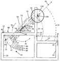
- FIG. 1is a perspective view of the free weight bar stabilizer of the present invention, showing the bar in a raised position supported on a vertical frame member;
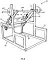
- FIG. 2is a perspective view similar to FIG. 1 , but showing the bar in a lowered position resting on the spotting rail;
- FIG. 3is a side elevation view of the bar stabilizer
- FIG. 4is a partial plan view, with structure eliminated to clearly show the carriage supported on the front section of the main beams;
- FIG. 5is an enlarged partial side elevational view showing the front section of the beam carrying the roller assembly of the carriage.
- FIG. 6is a partial plan view, with structure eliminated to clearly show the counterweight supported on the rear section of the main beams, and to show the linkage that interconnects the carriage and the counterweight.
- the free weight bar stabilizer that forms the basis of the present inventionis designated generally by the reference number 10 .
- the bar stabilizer 10includes a frame 20 , a pair of main beams 30 pivotally attached to the frame 20 , and a moveable carriage 40 supported on a front section 32 of the beams 30 .
- the stabilizer 10 shown in the drawingsfurther includes a carriage counterweight 60 supported on a rear section 34 of the beams 30 ; and also includes an assisting weight mechanism 80 . (not show in FIGS. 1-2 )
- the frame 20at each lateral side, supports a bearing 22 that receives a pivot shaft 24 disposed to rotate about a horizontal axis.
- the pivot shafts 24are positioned on each side of the frame 20 at an elevation of about thirty-six inches, which approximates the position of the hip joint of an average person.
- a beam 30is pivotally attached to each of the shafts 24 with a front section 32 and a rear sections 34 located fore and aft of the shafts 24 , respectively.
- the beams 30are disposed parallel to each other and move between a raised and lowered position in an arc shown by the directional arrow 36 .
- a linearly movable carriage 40is received on the front section 32 of each of the beams 30 .
- the carriage 40includes horizontally spaced arms 42 that each have a bearing 43 , with a set screw 44 , attached adjacent a bar receiving opening 45 at the distal end of the arms 42 .
- a roller assemblythat includes a roller bracket 48 carrying four rollers 50 , is attached to and movably interconnects the front section 32 of each of the beams 30 and a rear portion of the carriage 40 .
- a carriage brace 52assists and keeping the carriage arms 42 parallel to the front section 32 of the beams 30 .
- the carriage 40is linearly movable radially out from the beams 30 between a retracted and extended position shown by the directional arrow 46 .
- the combined angular range of motion of the beam 30 , and the linear range of motion of the bar receiving opening 45 on each of the carriage arms 42defines the envelope of operation 26 of the free weight stabilizer 10 .
- a standard Olympic bar 100is placed through the opening 45 and the bearing set screws 44 are tightened.
- the desired weightis added by attaching and securing barbell plates 150 at the ends of the bar 100 .
- the starting height of the bar 100may be anywhere in the envelope of operation 26 .
- FIG. 1shows the bar 100 on a bar rest 21 attached to a vertical member of the frame 20 at a starting height of about fifty-four inches, which approximates the position of the shoulders and neck of the average lifter.
- the envelope of operation 26 shownhas an upper limit defined by the location of the bar rest 21 , and a lower limit defined by the spotting rail 23 that extends out from the front of the frame 20 . If using the spotting rail 25 that is adjustable using pins 27 and holes 28 , as shown in dashed lines, the envelope of operation 26 would be reduced.
- brackets 62support a counterweight track 64 above and parallel to the rear section 34 of each of the beams 30 .
- a shaft 65extends transversely between the tracks 64 , and carries a counterweight 60 , secured by lock collars 68 , interior of each of the tracks 64 .
- a roller 70is attached at each end of the shaft 65 to engage the tracks 64 .
- the counterweights 60are attached to the rear section 34 of the beams 30 , and are moveable between a forward position and a rearward position as indicated by the directional arrow 66 .
- a linkageis provided to interconnect the carriage 40 and counterweight 60 . Using this linkage, as the carriage 40 moves from its retracted position to its extended position, the counterweight 60 simultaneously moves from its forward position to its rearward position.
- the linkageincludes two pulleys 72 , one attached to the front section 32 of the beams 30 and the other attached to the rear section 34 of the beams 30 by a pulley bracket 71 and a standoff 73 .
- a front section of cable 74has ends attached to an anchor 75 on the carriage 40 , and to an anchor 76 on the counterweight 60 .
- the cable 74is trained over the pulley 72 at the front section 32 of the beams 30 .
- a rear section of cable 74is also attached to the anchors 75 and 76 , and is trained over the pulley 72 at the rear section 34 of the beams 30 .
- Springs 78keep tension on the cable 74 .
- the movement of the carriage 40 in one directionresults in simultaneous movement of the counterweight 60 in the other direction to keep the beam 30 in balance.
- the lifterexperiences only the weight of the bar 100 and the attached barbell plates 150 .
- An assisting weight mechanism 80is provided that has an assisting weight bar rest 82 positioned at the rear of both sides of the frame 20 .
- An assisting weight bar pickup hook 84is carried on hook plate 86 attached at the rear section 34 of the beams 30 .
- the hook plates 86are connected by transverse tie bars 88 to keep them properly spaced and stabilized.
- Each of the hook plates 86are arcuate in shape, and include a number of openings 87 spaced in an arcuate path along the rear edge of the plates 86 .
- a selected one of the openings 87 on the hook plates 86is adapted to selectively receive and support a pickup hook 84 .
- Hooks 84attached at the same elevation on each of opposing plates 86 , are disposed to engage and lift and assisting weight bar 200 up from the bar rest 82 .
- the assist bar 200with any attached weights, is raised off the rest 82 , the total weight picked up becomes a counterweight to the front section 32 of the beams 30 that carries the weight of the main bar 100 and attached barbell plates 150 being lifted.
- the total weight being liftedis reduced at the predetermined point where the assist bar 200 is engaged by the hooks 84 and is raised.
- Changing the location of the pickup hooks 84 on the assist plates 86changes the point where the total weight being lifted is changed.
- the free weight bar stabilizer 10 of the present inventionis particularly useful as the device for strengthening the posterior muscle chain through the ‘good morning’ and the ‘Zercher’ lift routines. Other exercises such as squats, deadlifts, shrugs and various bench routines may also be performed using the bar stabilizer 10 .
- the assisting weight mechanism 80assists the lifter when working ‘heavy negatives’, by reducing the weight being lifted at a particular point in a routine, to allow the lifter to gradually work up to a heavier desired weight.
- the bar stabilizer 10allows the bar 100 to follow the lifter throughout the range of the movement within the working envelope of the bar 100 .
- the stabilizer 10prevents the bar 100 from tipping from side to side, and also prevents the bar 100 from rolling down the lifter's neck when approaching the lowest point of movement in the routine. Since the bar 100 is completely stabilized, the lifter can achieve the full depth of the routine, and the risk of injury is greatly reduced.
Landscapes
- Health & Medical Sciences (AREA)
- Life Sciences & Earth Sciences (AREA)
- Biophysics (AREA)
- Orthopedic Medicine & Surgery (AREA)
- General Health & Medical Sciences (AREA)
- Physical Education & Sports Medicine (AREA)
- Crystals, And After-Treatments Of Crystals (AREA)
- Cage And Drive Apparatuses For Elevators (AREA)
Abstract
Description
Claims (16)
Priority Applications (2)
| Application Number | Priority Date | Filing Date | Title |
|---|---|---|---|
| US15/856,230US10583319B2 (en) | 2017-12-28 | 2017-12-28 | Free weight bar stabilizer |
| US16/699,691US11247094B2 (en) | 2017-12-28 | 2019-12-01 | Free weight stabilizer bar |
Applications Claiming Priority (1)
| Application Number | Priority Date | Filing Date | Title |
|---|---|---|---|
| US15/856,230US10583319B2 (en) | 2017-12-28 | 2017-12-28 | Free weight bar stabilizer |
Related Child Applications (1)
| Application Number | Title | Priority Date | Filing Date |
|---|---|---|---|
| US16/699,691Continuation-In-PartUS11247094B2 (en) | 2017-12-28 | 2019-12-01 | Free weight stabilizer bar |
Publications (2)
| Publication Number | Publication Date |
|---|---|
| US20190201735A1 US20190201735A1 (en) | 2019-07-04 |
| US10583319B2true US10583319B2 (en) | 2020-03-10 |
Family
ID=67057892
Family Applications (1)
| Application Number | Title | Priority Date | Filing Date |
|---|---|---|---|
| US15/856,230Active2038-05-05US10583319B2 (en) | 2017-12-28 | 2017-12-28 | Free weight bar stabilizer |
Country Status (1)
| Country | Link |
|---|---|
| US (1) | US10583319B2 (en) |
Citations (19)
| Publication number | Priority date | Publication date | Assignee | Title |
|---|---|---|---|---|
| US4357010A (en)* | 1980-11-07 | 1982-11-02 | Telle Jerome R | Multipurpose exercising machine |
| US4406452A (en)* | 1981-12-24 | 1983-09-27 | Lapcevic Paul S | Weight lifting exercise device |
| US4746115A (en)* | 1987-03-09 | 1988-05-24 | Lahman Thomas E | Exercising device with controllable force pattern |
| US4858915A (en)* | 1986-07-02 | 1989-08-22 | Szabo William J | Weight-biased fitness machine |
| US5108095A (en)* | 1990-12-07 | 1992-04-28 | Southern Xercise, Inc. | Squat exercise apparatus |
| US5116297A (en)* | 1991-03-04 | 1992-05-26 | Stonecipher William L | Weight-lifting machine |
| US5217422A (en)* | 1992-01-06 | 1993-06-08 | Zel-X, Inc. | Compact exercise apparatus and method |
| US6482139B1 (en)* | 1999-01-18 | 2002-11-19 | Stanley Haag | Exercise apparatus |
| US20050148445A1 (en)* | 2004-01-05 | 2005-07-07 | Carle John T. | Weight exercise device |
| US20060040800A1 (en)* | 2004-08-19 | 2006-02-23 | Matt Slyter | Velocity weight training devices and method |
| US7104936B2 (en)* | 2003-05-27 | 2006-09-12 | Karlstrom David D | Strength and power training system |
| US7462141B1 (en)* | 2005-01-06 | 2008-12-09 | The United States Of America As Represented By The Administrator Of The National Aeronautics And Space Administration | Advanced resistive exercise device |
| US7488277B1 (en)* | 2000-11-17 | 2009-02-10 | Knapp Jeffrey M | Compact weightlifting frame system |
| US20090192026A1 (en)* | 2008-01-28 | 2009-07-30 | Mason Christopher M | Arm and shoulder lift apparatus |
| US8172731B1 (en)* | 2010-07-14 | 2012-05-08 | Ren Bredda | Gridiron power machine system |
| US8740760B2 (en)* | 2012-11-05 | 2014-06-03 | Ryan John York | Pivoting twin arm support for free weights |
| US20140256516A1 (en)* | 2013-03-07 | 2014-09-11 | Michael P. Calderone | Muscular evaluation and exercise device |
| US20160114205A1 (en)* | 2013-05-28 | 2016-04-28 | Marco Giunchi | Gymnastic machine |
| US9511258B2 (en)* | 2007-06-11 | 2016-12-06 | Richard J. Hoole | Weighted push-up exercise machine |
- 2017
- 2017-12-28USUS15/856,230patent/US10583319B2/enactiveActive
Patent Citations (19)
| Publication number | Priority date | Publication date | Assignee | Title |
|---|---|---|---|---|
| US4357010A (en)* | 1980-11-07 | 1982-11-02 | Telle Jerome R | Multipurpose exercising machine |
| US4406452A (en)* | 1981-12-24 | 1983-09-27 | Lapcevic Paul S | Weight lifting exercise device |
| US4858915A (en)* | 1986-07-02 | 1989-08-22 | Szabo William J | Weight-biased fitness machine |
| US4746115A (en)* | 1987-03-09 | 1988-05-24 | Lahman Thomas E | Exercising device with controllable force pattern |
| US5108095A (en)* | 1990-12-07 | 1992-04-28 | Southern Xercise, Inc. | Squat exercise apparatus |
| US5116297A (en)* | 1991-03-04 | 1992-05-26 | Stonecipher William L | Weight-lifting machine |
| US5217422A (en)* | 1992-01-06 | 1993-06-08 | Zel-X, Inc. | Compact exercise apparatus and method |
| US6482139B1 (en)* | 1999-01-18 | 2002-11-19 | Stanley Haag | Exercise apparatus |
| US7488277B1 (en)* | 2000-11-17 | 2009-02-10 | Knapp Jeffrey M | Compact weightlifting frame system |
| US7104936B2 (en)* | 2003-05-27 | 2006-09-12 | Karlstrom David D | Strength and power training system |
| US20050148445A1 (en)* | 2004-01-05 | 2005-07-07 | Carle John T. | Weight exercise device |
| US20060040800A1 (en)* | 2004-08-19 | 2006-02-23 | Matt Slyter | Velocity weight training devices and method |
| US7462141B1 (en)* | 2005-01-06 | 2008-12-09 | The United States Of America As Represented By The Administrator Of The National Aeronautics And Space Administration | Advanced resistive exercise device |
| US9511258B2 (en)* | 2007-06-11 | 2016-12-06 | Richard J. Hoole | Weighted push-up exercise machine |
| US20090192026A1 (en)* | 2008-01-28 | 2009-07-30 | Mason Christopher M | Arm and shoulder lift apparatus |
| US8172731B1 (en)* | 2010-07-14 | 2012-05-08 | Ren Bredda | Gridiron power machine system |
| US8740760B2 (en)* | 2012-11-05 | 2014-06-03 | Ryan John York | Pivoting twin arm support for free weights |
| US20140256516A1 (en)* | 2013-03-07 | 2014-09-11 | Michael P. Calderone | Muscular evaluation and exercise device |
| US20160114205A1 (en)* | 2013-05-28 | 2016-04-28 | Marco Giunchi | Gymnastic machine |
Also Published As
| Publication number | Publication date |
|---|---|
| US20190201735A1 (en) | 2019-07-04 |
Similar Documents
| Publication | Publication Date | Title |
|---|---|---|
| US5628715A (en) | Squat press exercise machine | |
| US9827460B2 (en) | Adjustable support for exercise system | |
| US10792532B1 (en) | Belt squat with cable-driven lever arm | |
| RU2403936C2 (en) | Training simulator for muscle-strengthening exercises and rehabilitation | |
| US10675502B2 (en) | Multi-functional exercise device | |
| US20020103058A1 (en) | Exercise arm apparatus with pivotal linkage system | |
| CA2623389C (en) | Training machine for strengthen training and rehabilitation | |
| US11247094B2 (en) | Free weight stabilizer bar | |
| US10729927B2 (en) | Exercise apparatus | |
| US4753437A (en) | Weightlifting exercise device | |
| US20060040810A1 (en) | Foldable gravity resistance gym | |
| US12296217B2 (en) | Dual action weightlifting machine with selectorized resistance | |
| US20240100390A1 (en) | Controlled squat strength-training machine | |
| EP3551300A1 (en) | Training device for carrying out balance, meditation and/or yoga exercises | |
| US20140287888A1 (en) | Bench halo | |
| US10583319B2 (en) | Free weight bar stabilizer | |
| US8944969B2 (en) | Rowing machine | |
| KR102340922B1 (en) | weight exercise equipment | |
| US20040097333A1 (en) | Fitness apparatus | |
| US11497958B2 (en) | Neck exercise apparatus | |
| DE102004027524A1 (en) | Multifunctional training device for strengthening the leg and back muscles comprises a seat consisting of a support rocker and a control rocker oscillating on a circular path | |
| US20140141941A1 (en) | Rowing machine | |
| KR102380657B1 (en) | Pectoralis Muscle Exercise Equipment | |
| KR102340918B1 (en) | weight up and down assembly of weight exercise equipment | |
| DE10119466A1 (en) | Training apparatus for arm muscles uses guide carriages on rail for continual adjustment of grip and lead arm travel circles to suit users arm dimensions |
Legal Events
| Date | Code | Title | Description |
|---|---|---|---|
| FEPP | Fee payment procedure | Free format text:ENTITY STATUS SET TO UNDISCOUNTED (ORIGINAL EVENT CODE: BIG.); ENTITY STATUS OF PATENT OWNER: SMALL ENTITY | |
| FEPP | Fee payment procedure | Free format text:ENTITY STATUS SET TO SMALL (ORIGINAL EVENT CODE: SMAL); ENTITY STATUS OF PATENT OWNER: SMALL ENTITY | |
| AS | Assignment | Owner name:ASSIST-A-LIFT, INC., IOWA Free format text:ASSIGNMENT OF ASSIGNORS INTEREST;ASSIGNORS:MORRIS, PATRICK A;BEAR, MORRIS R.;REEL/FRAME:045236/0034 Effective date:20180226 | |
| STPP | Information on status: patent application and granting procedure in general | Free format text:NON FINAL ACTION MAILED | |
| STPP | Information on status: patent application and granting procedure in general | Free format text:RESPONSE TO NON-FINAL OFFICE ACTION ENTERED AND FORWARDED TO EXAMINER | |
| STPP | Information on status: patent application and granting procedure in general | Free format text:PUBLICATIONS -- ISSUE FEE PAYMENT RECEIVED | |
| STCF | Information on status: patent grant | Free format text:PATENTED CASE | |
| MAFP | Maintenance fee payment | Free format text:PAYMENT OF MAINTENANCE FEE, 4TH YR, SMALL ENTITY (ORIGINAL EVENT CODE: M2551); ENTITY STATUS OF PATENT OWNER: SMALL ENTITY Year of fee payment:4 |