US10583058B2 - Person support apparatus having physiological sensor - Google Patents
Person support apparatus having physiological sensorDownload PDFInfo
- Publication number
- US10583058B2 US10583058B2US16/149,400US201816149400AUS10583058B2US 10583058 B2US10583058 B2US 10583058B2US 201816149400 AUS201816149400 AUS 201816149400AUS 10583058 B2US10583058 B2US 10583058B2
- Authority
- US
- United States
- Prior art keywords
- support apparatus
- controller
- sensor
- patient support
- person
- Prior art date
- Legal status (The legal status is an assumption and is not a legal conclusion. Google has not performed a legal analysis and makes no representation as to the accuracy of the status listed.)
- Active
Links
Images


Classifications
- A—HUMAN NECESSITIES
- A61—MEDICAL OR VETERINARY SCIENCE; HYGIENE
- A61B—DIAGNOSIS; SURGERY; IDENTIFICATION
- A61B5/00—Measuring for diagnostic purposes; Identification of persons
- A61B5/02—Detecting, measuring or recording for evaluating the cardiovascular system, e.g. pulse, heart rate, blood pressure or blood flow
- A61B5/0205—Simultaneously evaluating both cardiovascular conditions and different types of body conditions, e.g. heart and respiratory condition
- A61B5/02055—Simultaneously evaluating both cardiovascular condition and temperature
- A—HUMAN NECESSITIES
- A61—MEDICAL OR VETERINARY SCIENCE; HYGIENE
- A61G—TRANSPORT, PERSONAL CONVEYANCES, OR ACCOMMODATION SPECIALLY ADAPTED FOR PATIENTS OR DISABLED PERSONS; OPERATING TABLES OR CHAIRS; CHAIRS FOR DENTISTRY; FUNERAL DEVICES
- A61G7/00—Beds specially adapted for nursing; Devices for lifting patients or disabled persons
- A61G7/002—Beds specially adapted for nursing; Devices for lifting patients or disabled persons having adjustable mattress frame
- A61G7/005—Beds specially adapted for nursing; Devices for lifting patients or disabled persons having adjustable mattress frame tiltable around transverse horizontal axis, e.g. for Trendelenburg position
- A—HUMAN NECESSITIES
- A61—MEDICAL OR VETERINARY SCIENCE; HYGIENE
- A61B—DIAGNOSIS; SURGERY; IDENTIFICATION
- A61B5/00—Measuring for diagnostic purposes; Identification of persons
- A61B5/02—Detecting, measuring or recording for evaluating the cardiovascular system, e.g. pulse, heart rate, blood pressure or blood flow
- A61B5/024—Measuring pulse rate or heart rate
- A—HUMAN NECESSITIES
- A61—MEDICAL OR VETERINARY SCIENCE; HYGIENE
- A61B—DIAGNOSIS; SURGERY; IDENTIFICATION
- A61B5/00—Measuring for diagnostic purposes; Identification of persons
- A61B5/103—Measuring devices for testing the shape, pattern, colour, size or movement of the body or parts thereof, for diagnostic purposes
- A61B5/11—Measuring movement of the entire body or parts thereof, e.g. head or hand tremor or mobility of a limb
- A61B5/1113—Local tracking of patients, e.g. in a hospital or private home
- A61B5/1115—Monitoring leaving of a patient support, e.g. a bed or a wheelchair
- A—HUMAN NECESSITIES
- A61—MEDICAL OR VETERINARY SCIENCE; HYGIENE
- A61B—DIAGNOSIS; SURGERY; IDENTIFICATION
- A61B5/00—Measuring for diagnostic purposes; Identification of persons
- A61B5/103—Measuring devices for testing the shape, pattern, colour, size or movement of the body or parts thereof, for diagnostic purposes
- A61B5/11—Measuring movement of the entire body or parts thereof, e.g. head or hand tremor or mobility of a limb
- A61B5/1126—Measuring movement of the entire body or parts thereof, e.g. head or hand tremor or mobility of a limb using a particular sensing technique
- A—HUMAN NECESSITIES
- A61—MEDICAL OR VETERINARY SCIENCE; HYGIENE
- A61B—DIAGNOSIS; SURGERY; IDENTIFICATION
- A61B5/00—Measuring for diagnostic purposes; Identification of persons
- A61B5/68—Arrangements of detecting, measuring or recording means, e.g. sensors, in relation to patient
- A61B5/6887—Arrangements of detecting, measuring or recording means, e.g. sensors, in relation to patient mounted on external non-worn devices, e.g. non-medical devices
- A61B5/6892—Mats
- A—HUMAN NECESSITIES
- A61—MEDICAL OR VETERINARY SCIENCE; HYGIENE
- A61B—DIAGNOSIS; SURGERY; IDENTIFICATION
- A61B5/00—Measuring for diagnostic purposes; Identification of persons
- A61B5/103—Measuring devices for testing the shape, pattern, colour, size or movement of the body or parts thereof, for diagnostic purposes
- A61B5/11—Measuring movement of the entire body or parts thereof, e.g. head or hand tremor or mobility of a limb
- A61B5/1116—Determining posture transitions
- A61B5/1117—Fall detection
Definitions
- This disclosurerelates to person support apparatuses such as hospital beds. More particularly, the present disclosure relates to person support apparatuses having sensors that sense one or more conditions of the person or of the apparatus.
- Person support apparatusesinclude beds, chairs, stretchers, seats, mattresses, therapy surfaces, furniture, and the like, or other apparatuses that support a person.
- Hospital beds and stretchers, hospital mattresses, and wheelchairsare examples of such apparatuses that support persons.
- Consumer beds, chairs, and furnitureare also examples of such person support apparatuses, as are seats for vehicles, businesses, and venues.
- Vital signs monitorsmonitor one or more physiological parameters of a person, such as body temperature, pulse rate, heart rate, blood pressure, and respiratory rate, as well as other body signs, such as end-tidal CO2, SpO2 (saturation of oxygen in arterial blood flow), and other indicators of the person's physiological state.
- Position and movement detection systemsmonitor the position and/or movement of a person to determine if they are attempting to exit the support apparatus.
- a person support apparatusmay include a frame and a support surface cooperating with the frame to support a person.
- the person support apparatusmay also have a sensor coupled to one of the frame and the support surface, the sensor detecting at least one characteristic associated with the person.
- a controllermay be coupled to the sensor. In response to at least one of a condition of the frame, a condition of the support surface, a position of the person, or a condition of the person, the controller may operate to control the sensor by at least one of changing a gain of the sensor and changing a manner in which a signal from the sensor is filtered.
- the controllermay also be operable to turn the sensor on and off.
- the sensormay include a plurality of sensors and the controller may operate to control each of the plurality of sensors by at least one of changing a gain of each of the plurality of sensors and changing a manner in which signals from each of the plurality of sensors is filtered.
- the controllermay operate to turn off some of the plurality of sensors and to turn on others of the plurality of sensors.
- the determination by the controller as to which sensors may be turned off and which sensors may be turned onmay be based on a position of the person relative to the support surface or relative to the frame. Alternatively or additionally, the determination by the controller as to which sensors may be turned off and which sensors may be turned on may be based on movement of a first portion of the frame relative to a second portion of the frame.
- the controllermay be operable to implement via software at least one of a high pass filter, a low pass filter, and a band pass filter and/or the controller may be operable to selectively switch the sensor between being coupled to a high pass filter, a low pass filter, and a band pass filter.
- the controllermay be operable to filter out noise associated with at least one of a first electric component associated with the support surface and a second electric component associated with the frame.
- the controllermay be operable to filter out noise associated with separate medical equipment in a person's room based on information received from an electronic medical record (EMR) system.
- EMRelectronic medical record
- the sensormay comprise a force sensing load cell coupled to the frame or a pressure sensing strip coupled to the support surface or both.
- the support surfacemay comprise a mattress that may have inflatable bladders and the sensor may include a pressure sensor that measures pressure in at least one of the bladders.
- the sensormay sense at least one of the person's weight, heart rate, respiration rate, and temperature.
- the at least one characteristic associated with the person and sensed by the sensormy include at least one of a force profile, a pressure in a bladder, and a physiological characteristic.
- the controllermay adjust the gain of the sensor as a function of a difference between a first position of the person relative to one of the frame and the support surface and a second position of the person relative to one of the frame and the support surface.
- the controllermay be operable to prevent a user from accessing predetermined functions of the person support apparatus based on at least one of signal strength and clarity of a signal from the sensor.
- the sensormay include a plurality of sensors and the controller may control the gain of each of the plurality of sensors such that signal strength of an output signal of each of the plurality of sensors may be substantially equal.
- the sensormay include a first sensor and a second sensor and the controller may operate to amplify a signal from the first sensor when signal strength of the signal from the first sensor is less than that of the second sensor. Alternatively or additionally, a signal from the first sensor may be filtered when signal clarity of the signal from the first sensor is less than that of the second sensor.
- a systemmay be configured to select between a first sensor and a second sensor based on at least one of the position of a person on a person support surface, the pressure in support surface fluid bladders, a difference between the signal strength and/or clarity of the first sensor and a signal strength and/or clarity of a second sensor, and person support apparatus status information.
- a systemmay be configured to amplify and/or filter a signal from a first sensor as a function of at least one of a difference between the signal strength and/or clarity of the first sensor and a signal strength and/or clarity of a second sensor, the position of a person on a person support surface, the pressure in support surface fluid bladders, a comparison between a first sensor and second sensor, and person support apparatus status information.
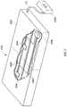
- FIG. 1is a perspective view of an embodiment of a person support apparatus according to one illustrative embodiment
- FIG. 2is perspective view of the person support surface of FIG. 1 according to one illustrative embodiment partially cut away to reveal sensors integrated therein;
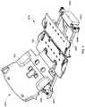
- FIG. 3is a perspective view of the upper frame according to one illustrative embodiment of the person support apparatus of FIG. 1 ;
- FIG. 4is a diagrammatic view of a control system for the person support apparatus of FIG. 1 according to one illustrative embodiment
- FIG. 5is a diagrammatic view of a control system for the person support apparatus of FIG. 1 according to another illustrative embodiment
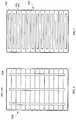
- FIG. 6is a top view of the fluid bladders within the person support surface of FIG. 2 with pressure sensors coupled across the bladders according to one illustrative embodiment
- FIG. 7is a top view of the fluid bladders within the person support surface of FIG. 2 with pressure sensors coupled along the bladders according to another illustrative embodiment
- FIG. 8is a top view of the fluid bladders within the person support surface of FIG. 2 with pressure sensors integrated in the bladders according to yet another illustrative embodiment
- FIG. 9is a flowchart for a procedure that can be executed by the control system of FIGS. 4 and/or 5 according to one illustrative embodiment
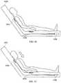
- FIG. 10is a partial diagrammatic view of a person in a first position with respect to the person support surface of FIG. 1 according to one illustrative embodiment
- FIG. 11is a partial diagrammatic view of a person in a second position with respect to the person support surface of FIG. 1 ;
- FIG. 12is a flowchart for a procedure that can be executed by the control system of FIGS. 4 and/or 5 according to one illustrative embodiment.
- FIG. 13is a flowchart for a procedure that can be executed by the control system of FIGS. 4 and/or 5 according to one illustrative embodiment.
- One illustrative embodiment of the present disclosureincludes a system configured to select between a first sensor and a second sensor based on at least one of the position of a person on a person support surface, the pressure in support surface fluid bladders, a difference between the signal strength and/or clarity of the first sensor and a signal strength and/or clarity of a second sensor, and person support apparatus status information.
- Another illustrative embodimentincludes a system configured to amplify and/or filter a signal from a first sensor as a function of at least one of a difference between the signal strength and/or clarity of the first sensor and a signal strength and/or clarity of a second sensor, the position of a person on a person support surface, the pressure in support surface fluid bladders, a comparison between a first sensor and second sensor, and person support apparatus status information.
- FIG. 1A person support apparatus 1010 according to an illustrative embodiment of the current disclosure is shown in FIG. 1 .
- the person support apparatus 10includes a head section H 1 , where the head and a portion of the torso of a person (not shown) can be positioned, and a foot section F 1 , where the feet of a person (not shown) can be positioned.
- the person support apparatus 1010includes a lower frame 1012 or base 1012 , an upper frame 1014 , a plurality of supports 1016 , a fluid supply 1018 , and a control system 1020 . In some embodiments, the person support apparatus 1010 includes only one support 1016 .
- the lower frame 1012includes at least one lower frame section that is supported by casters 1022 as shown in FIG. 1 .
- the person support apparatus 1010supports a person support surface 1024 or mattress 1024 on the upper frame 1014 as shown in FIGS. 1, 2 , & 6 - 8 .
- the person support surface 1024is configured to support a person (not shown) in multiple articulated positions.
- the person support surface 1024includes a back portion B 1 and a main portion M 1 .
- the person support surface 1024includes a cover 1026 or ticking 1026 that envelopes one or more support sections and/or layers having foam and/or fluid bladders 1028 .
- the person support surface 1024is configured to deliver therapy to the person, such as, for example, through sequential inflation/deflation of the fluid bladders 1028 , rapid changes in pressure of the fluid in the fluid bladders 1028 , and/or passing fluid through the person support surface 1024 .
- one or more portions of the surface 1024provides alternating pressure therapy, continuous lateral rotation therapy, low air loss therapy, boost assistance, percussion/vibration therapy, and/or other therapies.
- the person support surface 1024includes a coverlet (not shown) that overlies another person support surface 1024 and that is configured to deliver therapy to a person supported thereon.
- the supports 1016are coupled with the upper frame 1014 and the lower frame 1012 and define a vertical axis Z 1 that extends through the lower frame 1012 and the upper frame 1014 substantially perpendicular when the lower frame 1012 and the upper frame 1014 are parallel one another as shown in FIG. 1 .
- the supports 1016are lift mechanisms 1016 with a lift driver (not shown) that causes the lift mechanisms 1016 to expand and/or contract to raise and/or lower the upper frame 1014 with respect to the lower frame 1012 .
- the supports 1016include at least one of telescoping towers, scissor lifts, rotational lifts, hydraulic lifts or actuators, pneumatic lifts or actuators, linear actuators, electronic actuators, chain lifts, or other lift mechanisms.
- the supports 1016comprise at least one fixed column (not shown). According to some embodiments, the supports 1016 move the upper frame 1014 to a Trendelenburg/reverse Trendelenburg position and/or rotate the upper frame 1014 from side to side with respect to the lower frame 1012 .
- the upper frame 1014defines a longitudinal axis X 1 that extends at least the length of the person support apparatus 1010 through the head end H 1 and the foot end F 1 along the lateral center of the upper frame 1014 , and a lateral axis Y 1 that is perpendicular to the longitudinal axis X 1 and extends at least the width of the person support apparatus 1010 through the longitudinal center of the upper frame 1014 as shown in FIGS. 1 and 3 .
- the upper frame 1014includes a deck 1030 , an intermediate frame 1032 , and an upper frame base 1034 coupled to the supports 1016 which support the deck 1030 and the intermediate frame 1032 .
- the upper frame 1014also includes a footboard FB, a head board HB, and/or siderails SR supported by the intermediate frame 1032 .
- the upper frame 1014only includes a deck 1030 .
- the deck 1030has multiple sections, such as, a head deck section HD, a seat deck section SD, and a foot deck section FD, that are pivotably coupled to one another and/or the deck 1030 and articulate about the lateral axis Y 1 .
- the fluid supply 1018couples to the person support surface 1024 through a conduit C 1 and is configured to supply fluid to the fluid bladders 1028 of the person surface 1024 as shown in FIG. 3 .
- the fluid supply 1018also supplies fluid to the coverlet (not shown).
- the fluid supply 1018supplies gas to the person support surface 1024 .
- the fluid supply 1018includes a fluid source (not shown) such as an air blower (not shown) or an air compressor (not shown).
- the fluid supply 1018includes a user interface (not shown) and/or a controller (not shown) that controls the operation of the fluid source in response to an input from a user or control system, such as, control system 1020 .
- the control system 1020includes a plurality of sensors 1036 and control modules 1038 as shown in FIGS. 5 and 6 .
- the control system 1020is configured to control various functions of the person support apparatus 1010 including, but not limited to, for example, articulating the deck 1030 with respect to the intermediate frame 1032 , administering therapy to a person supported on the person support apparatus 1010 , alerting caregivers when a person is exiting the person support apparatus 1010 , alerting caregivers when a person is out of a desired position relative to the person support surface 1024 , output information processed by the control system 1020 to a display (not shown), etc.
- the control system 1020is coupled to the upper frame 1014 in some instances.
- control system 1020is coupled to the lower frame 1012 , supports 1016 , a siderail, and/or elsewhere on the person support apparatus 1010 .
- control system 1020is incorporated within or coupled to the person support surface 1024 .
- control modules 1038are integrated into a graphical user interface (not shown).
- control system 1020is integrated into an external network (not shown), such as, a hospital network, in communication with the person support apparatus 1010 .
- the sensors 1036are operatively coupled to the control modules 1038 and are configured to sense various parameters, including, but not limited to, for example, a person's physiological information, a position of a person on the person support apparatus 1010 and/or person support surface 1024 , a pressure of the fluid inside the bladders 1028 in the person support surface 1024 , or other various parameters.
- the sensors 1036comprise force sensors 1040 that are coupled to the upper frame 1014 and that are configured to measure force on the upper frame 1014 as shown in FIGS. 5 and 6 .
- the sensors 1036are force sensors 1040 that are configured to measure force on the upper frame 1014 and that are positioned between the intermediate frame 1032 and the upper frame base 1034 so as to couple the intermediate frame 1032 and deck 1030 to the upper frame base 1034 .
- the sensors 1036are force sensors 1040 that are integrated into the person support surface 1024 and that are configured to measure changes in force on the person support surface 1024 as shown in FIG. 2 .
- the force sensors 1040are coupled to the supports 1016 and/or the lower frame 1012 .
- the sensors 1036are integrated into the casters 1022 and/or are engaged by the casters 1022 . It is within the scope of this disclosure for the sensors 1036 to be integrated into the ticking 1026 such as being between the layers of the ticking 1026 .
- the force sensors 1040are load cells 1040 that are coupled proximate the corners of the intermediate frame 1032 .
- the force sensors 1040are piezoelectric sensors and/or elongated sensor strips or arrays. In other embodiments, the force sensors 1040 are other types of force sensors 1040 and are positioned in other locations on the upper frame 1014 and/or within the person support surface 1024 .
- the sensors 1036are pressure sensors 1042 that are integrated into the person support surface 1024 and that are configured to measure the pressure in/among the fluid bladders 1028 in the person support surface 1024 as shown in FIGS. 6-8 .
- the pressure sensors 1042are coupled between the bladders 1028 such that they allow communication between adjacent bladders 1028 . It some embodiments, the pressure sensors are situated within the bladders 1028 and measure the pressure within the bladder 1026 .
- the sensors 1036are physiological sensors 1044 that are integrated into the person support surface 1024 and that are configured to measure one or more physiological parameters of a person supported on the person support surface 1024 as shown in FIG. 2 .
- the force sensors 1040 and one or more of the pressure sensors 1042sense different physiological parameters in some embodiments.
- the physiological sensors 1044are used to sense the heart rate and/or respiration rate of a person supported on the person support surface 1024 .
- oen or more of the physiological sensors 1044sense the temperature of the person. It also contemplated by this disclosure for the physiological sensors 1044 to be configured to sense the movement and/or weight of the person on the person support surface 1024 .
- one or more of the physiological sensors 1044are configured to sense the relative humidity of a tissue on the person support surface 1024 .
- the physiological sensors 1044are pressure-strip sensors disposed on the fluid bladders 1028 along an axis parallel with the lateral axis Y 1 and/or along an axis parallel with the longitudinal axis X 1 .
- the control modules 1038are each configured to perform different operations in the illustrative example. However, in some embodiments, a single control module 1038 is configured to perform the multiple different operations. In some embodiments, a single control module 1038 is configured to perform operations independently or in conjunction with at least one other control module 1038 .
- a first control module 1038such as, a person position monitor module 1046 (PPM) is configured to detect the position of a person on the person support apparatus 1010 .
- a second control module 1038such as a therapy control module 1048 , is configured to sense and/or modify the pressure within the fluid bladders 1028 .
- a third control module 1038such as a physiological parameter monitor module 1050 , is configured to detect a person's physiological information.
- the control modules 1038are operatively coupled together through a network 1052 as shown in FIGS. 4 and 5 .
- the network 1052facilitates communication between the various modules and/or equipment connected to the network 1052 .
- the network 1052is a CAN network on a person-support apparatus 1010 .
- the network 1052comprises a hospital network (not shown).
- the network 1052includes other types of networks or communication protocols that facilitate communication between two or more devices. It is contemplated by this disclosure that the modules 1038 can be configured to connect to the network 1052 wirelessly, if desired.
- the control modules 1038negotiate with the network 1052 to be a network node.
- the control modules 1038are located at or on any node on the network 1052 and/or distributed across multiple nodes on the network 1052 .
- the control modules 1038are implemented using software and/or hardware. In some embodiments, the control modules 1038 are implemented in software and are configured to perform one or more operations as shown in FIGS. 4 and 5 . In some embodiments, the modules 1038 are configured to communicate via a memory mailbox where information from one module is sent to the memory address of a recipient module. In other embodiments, the software modules are configured to push information to a memory location, such as, a stack, that the control modules 1038 monitor or periodically check for information that the software modules subscribe to.
- control modules 1038are implemented using hardware.
- the control modules 1038include a controller 1054 or processor 1054 and memory 1056 as shown in FIGS. 4 and 5 .
- the controller 1054is provided as a single component or a collection of operatively coupled components; and is comprised of digital circuitry, analog circuitry, or a hybrid combination of both of these types.
- controller 1054has one or more components remotely located relative to the others in some instances.
- the controller 1054includes, for example, multiple processing units arranged to operate independently, in a pipeline processing arrangement, in a parallel processing arrangement, and/or such different arrangement as would occur to those skilled in the art.
- processor 1054is a programmable microprocessing device of a solid-state, integrated circuit type that includes one or more processing units and memory. It is within the scope of this disclosure for the controller 1054 to include one or more signal conditioners, modulators, demodulators, Arithmetic Logic Units (ALUs), Central Processing Units (CPUs), limiters, oscillators, control clocks, amplifiers, signal conditioners, filters, format converters, communication ports, clamps, delay devices, memory devices, and/or different circuitry or functional components as would occur to those skilled in the art to perform the desired communications.
- the controller 1054includes a computer network interface to communicate among various system components and/or components not included in the depicted system, as desired. The listed examples are not intended to be an exhaustive list of structures that are within the scope of controller 1054 , but are instead only a non-exhaustive list of such structures which can have substantial differences in the manner in which they are implemented and/or operate.
- the controller 1054is operatively coupled with the sensors 1036 and receives information from the sensors 1036 .
- one or more of the sensors 1036are operatively coupled to the network 1052 and the controller 1054 receives the information from the sensors 1036 and outputs from other modules 1038 via the network 1052 .
- one or more of the sensors 1036are configured to produce an analog data signal and are connected directly to the controller 1054 .
- one or more of the sensors 1036are configured to produce a digital data signal, e.g., a serial digital data signal, that is transmitted to the network 1052 , e.g., a Serial Peripheral Interface (SPI) network 1052 , to communicate with the controller 1054 .
- the signalsare stored in the memory 1056 , which is operatively coupled with the controller 1054 .
- the memory 1056is integrated into the controller 1054 .
- the controller 1054is configured to execute operating logic 1058 that defines various control, management, and/or regulation functions as shown in FIGS. 9, 12 and 13 .
- the software implemented modulesinclude operating logic 1058 .
- the operating logic 1058is in the form of software, firmware, and/or dedicated hardware, such as, a series of programmed instructions, code, electronic files, or commands using general purpose or special purpose programming languages or programs executed on one or more general purpose or special purpose computers, processors, other control circuitry, or networks; a hardwired state machine; and/or a different form as would occur to those skilled in the art.
- one of the control modules 1038is a patient position monitoring (PPM) module 1046 .
- the memory 1056 of the controller 1054includes operating logic 1058 with a number of software algorithms and other data that is executed by the controller 1054 to monitor patient movement relative to a reference load cell 1040 distribution, impending exit from the person support surface 1024 and/or exit therefrom.
- the operating logic 1058 for managing such functionsis in accordance with FIG. 5 in the form of a combined flowchart and/or state machine.
- the operating logic 1058is executed periodically by the controller 1054 , e.g., once every 200 ms, to monitor patient movement relative to a reference load cell 1040 distribution, impending exit from the mattress 1024 and/or exit from the mattress 1024 .
- the operating logic 1058begins with the controller 1054 determining whether the person position monitor module 1046 is armed, i.e., whether one of the patient monitoring modes was active, before the last power down of the person position monitor module 1046 .
- the patient monitoring modesincludes a patient movement (PM) mode wherein the person position monitor module 1046 is operable to monitor movement of a patient on the mattress 1024 by monitoring weight distribution among two or three of the four load cells 1040 relative to a predefined set of PM load cell threshold data, a patient exit (PE) mode wherein the person position monitor module 1046 is operable to monitor impending exit from the mattress 1024 by monitoring weight distribution of the four load cells 1040 relative to a predefined set of PE load cell threshold data, and a patient out-of-bed ( 00 B) mode wherein the person position monitor module 1046 is operable to monitor exit of the patient from the mattress 1024 by monitoring the patient weight distributed over the four load cells 1040 relative to an alined patient weight, wherein the armed weight corresponds to the patient weight distributed over the four load cells 1040 when the patient monitoring mode was armed as will be described in greater detail hereinafter.
- PMpatient movement
- PEpatient exit
- 00 Bpatient out-of-bed
- execution of the operating logic 1058causes the controller 1054 to execute a state machine preparation routine. If the controller 1054 instead determines that the person position monitor module 1046 was armed before the last system power down, execution of the operating logic 1058 advances to an Arming From Power Up Transition State of the state machine where the patient weight is processed to determine whether it is contained within a defined armed range prior to advancing to the PM Active State of the state machine to resume operation of the patient monitoring mode that was active at the last system power down.
- an Arming From Power Up Transition State of the state machinewhere the patient weight is processed to determine whether it is contained within a defined armed range prior to advancing to the PM Active State of the state machine to resume operation of the patient monitoring mode that was active at the last system power down.
- the controller 1054detects the ingress/egress of a person to/from the person-support apparatus 1010 by determining the center of gravity of the weight thereon.
- a person to/from the person-support apparatus 1010detects the center of gravity of the weight thereon.
- One example of such a systemcan be found in U.S. Pat. No. 5,276,432 to Travis, issued on Jan. 4, 1994.
- the controller 1054treats the upper frame 1014 as though it were disposed within a horizontal plane, extracts from the weight value measured by each load cell 1040 a portion which represents the weight of a patient, uses the extracted portions to calculate the location within the plane of a center of gravity of the patient, determines whether the location of the center of gravity is inside or outside a predetermined region which is a portion of the plane, and initiates an alarm when it is found that the center of gravity is located outside the predetermined region.
- a predetermined regionwhich is a portion of the plane
- the controller 1054 of the PPM module 1046includes operating logic 1058 in the form of procedure 1060 , for example, as shown in the flowchart of FIG. 9 .
- Procedure 1060includes operations/conditionals shown in blocks 1062 , 1064 , 1066 , 1068 , 1070 , and 1072 .
- Procedure 1060evaluates changes in the force profile (FP) for the surface 1024 as a function of the difference between the last sensed force values (LSFV) and the newly sensed force values (NSFV) as represented by the following equation:
- Procedure 1060begins with the operation of block 1062 where, in some embodiments, the force sensors 1040 post an electronic data signal representing at least one of an event and an amount of force on the network 1052 .
- the force sensors 1040post data signals continuously and/or over at predetermined intervals.
- the force sensors 1040post data signals in response to a query from a PPM module 1046 .
- the data signalsinclude information that identifies what operations and/or control modules 1038 the data can be utilized by. It should also be appreciated that posting can mean sending data out on a network.
- the sensors 1036are operatively coupled directly to specific control modules 1038 , for example, the force sensors 1040 being operatively coupled to the PPM module 1046 , the pressure sensors 1042 being operatively coupled to a therapy control module 1048 , and the physiological sensors 1044 being operatively coupled to a physiological parameter monitor module 1050 .
- the PPM module 1046examines the data signal posted by the force sensors 1040 on the network 1052 and determines whether or not the PPM module 1046 performs any operations that utilize the data as an input, i.e., whether or not the PPM module 1046 subscribes to the data signal.
- Other control modules 1038such as, the therapy control module 1048 and/or the physiological parameter monitor module 1050 , also subscribe to the force sensor 1040 data signal and receives the data as an input, while control modules 1038 that do not subscribe to the data disregard the data and wait for data signals to be posted that they do subscribe to.
- the controller 1054 of the PPM module 1046inputs the data into the control logic 1058 that utilizes the data as an input.
- the controller 1054stores the posted data in the memory 1056 and compares previously posted data and newly input data to determine changes in the force profile of a person on the surface 1024 , i.e., determine if and where a person has moved with respect to the surface 1024 .
- the controller 1054determines if changes in the force profile are greater than a predetermined threshold. Changes in the force profile can potentially signify that the person is positioned higher on the surface 1024 , i.e., more toward the head end H 1 of the person support apparatus 1010 , than desired; or that the person is positioned lower on the surface 1024 , i.e., more toward the foot end F 1 of the person support apparatus 1010 , than desired. See FIGS. 10 and 11 . In some embodiments, changes in the force profile is used to determine whether the person has moved to a side of the surface 1024 and/or how much they have moved with respect to the surface 1024 .
- Such a determinationis helpful in predicting whether the person is going to exit the person support apparatus 1010 , adjusting the sensitivity of the sensors 1036 to compensate for movement, when a person is beginning to wake up, and/or whether continued therapy in the new/current position is desirable, or various other situations.
- the controller 1054proceeds to determine whether or not the PPM system is armed, i.e., whether or not the PPM module 1046 is set to monitor the position of the person on the person support apparatus 1010 .
- a caregiver and/or the person on the person support apparatus 1010activates and deactivates the PPM system locally through a caregiver interface on the person support apparatus 1010 or remotely. If the PPM system is armed, then the controller 1054 generates an alert signal in the operation of block 1072 to alert a caregiver that the person on the person support apparatus 1010 is about to exit the person support apparatus 1010 .
- the controller 1054also communicates the amount the person has moved with respect to the person support apparatus 1010 .
- the controller 1054communicates the alert signal wirelessly or over a hospital network or an adverse condition alert system, such as, the Navicare® system sold by Hill-Rom Company, Inc., a caregiver station, a mobile paging device, a cellular phone, a pendant, over an intercom, or through other caregiver notification methods and devices. If the PPM system is not armed, then the controller 1054 returns to the operation of block 1062 .
- the controller 1054generates signals representative of an event, e.g., the person has moved toward the head section H 1 , and/or an amount that the person has moved with respect to the person support apparatus 1010 and post the signals back on the network 1052 before returning to operation 1062 since other control modules 1038 can subscribe to the output of the PPM module 1046 .
- the controller 1054prevents a user from accessing specific features on a user interface (not shown) based on the movement/positioning of the person on the person support surface 1024 .
- one of the control modules 1038is a therapy control module 1048 .
- the therapy control module 1048is operatively coupled to the pressure sensors 1042 and the fluid supply 1018 .
- the therapy control module 1048controls various therapies that are administered to the person, such as, lateral rotation, percussion vibration, low air loss, or other therapies.
- the therapy control module 1048includes operating logic 1058 in the form of procedure 1074 , for example, as shown in the flowchart of FIG. 12 .
- Procedure 1074includes the operations/conditionals of blocks 1076 , 1078 , 1080 , 1082 , and 1084 .
- Procedure 1074begins with the operation of block 1076 where, in some embodiments, the pressure sensors 1042 post an electronic data signal representing at least one of an event and an amount on the network 1052 .
- the therapy control module 1048examines the data signal posted by the pressure sensors 1042 on the network 1052 and determines whether or not the therapy control module 1048 performs any operations that utilize the data as an input, i.e., whether or not the therapy control module 1048 subscribes to the data signal.
- the controller 1054 of the therapy control module 1048inputs the data into the control logic that utilizes the data as an input.
- the controller 1054 of the therapy control module 1048inputs the data into the therapy control logic 1058 .
- the controller 1054stores the posted data in the memory 1056 and compares previously posted data and newly input data to determine changes in the pressure profile of a person on the surface 1024 , i.e., determine if, where, and by how much a person has moved with respect to the surface 1024 .
- the controller 1054determines if changes in the force profile are greater than a predetermined threshold. Changes in the pressure profile can potentially signify that the person is positioned higher on the surface 1024 , i.e., more toward the head end H 1 of the person support apparatus 1010 , than desired; or that the person is positioned lower on the surface 1024 , i.e., more toward the foot end F 1 of the person support apparatus 1010 , than desired. In some embodiments, changes in the pressure profile is used to determine whether the person has moved toward a side of the surface 1024 and/or how much they have moved with respect to the surface 1024 . Such a determination is helpful in predicting whether the person is going to exit the person support apparatus 1010 and/or whether therapy in the current position or a new position is desirable.
- the controller 1054determines in the conditional of block 1082 that the change in the force profile exceeded the predetermined threshold, the controller 1054 cooperates with the fluid supply 1018 to modify various characteristics of the support surface 1024 .
- the controller 1054cooperates with the fluid supply 1018 to adjust the pressure of the fluid within the fluid bladders 1028 as a function of the movement.
- the pressure in the fluid bladders 1028is changed to maintain a comfort level of a person by reducing the pressure in some bladders 1028 and increasing the pressure in other bladders 1028 to compensate for the movement of the person.
- the controller 1054cooperates with the fluid supply 1018 to adjust a therapy, such as, continuous lateral rotation, percussion vibration, or other therapies, as a function of the movement.
- a therapysuch as, continuous lateral rotation, percussion vibration, or other therapies
- the therapyis stopped completely or at least until the person moves back to within a predetermined range of the previous position.
- the controller 1054generates signals representative of an event, e.g., the pressure profile has changed, which can potentially signify movement of the person with respect to the surface 1024 , and/or an amount that the pressure has increased, or an amount the pressure profile has changed and post the signals back on the network 1052 before returning to operation 1076 , since other control modules 1038 subscribe to the output of therapy control module 1048 in some instances.
- one or more of the control modules 1038are a physiological parameter monitor module 1050 .
- the physiological parameter monitor module 1050is operatively coupled with the physiological sensors 1044 .
- the physiological parameter monitor module 1050includes operating logic 1058 in the form of procedure 1086 .
- procedure 1086evaluates changes in the physiological sensor signal strength and/or clarity (PS) for the surface 1024 to determine whether a first physiological sensor 1044 would provide a more desirable signal and should be used instead of a second physiological sensor 1044 .
- PSphysiological sensor signal strength and/or clarity
- Information from the PPM system of the person support apparatusmay be used to determine that the sensors 1044 on the left half of the apparatus should be turned on and the sensors on the right half 1044 should be turned off based on the position of the patient being more toward the left half of the apparatus, or vice versa.
- Other subsets of the sensorsmay be turned on and off in other scenarios such as, for example, turning on sensors in a seat section if the PPM system indicates that the patient is likely sitting up while turning off sensors in zones or sections of the person support apparatus that are no longer supporting a person.
- procedure 1086subscribes to data on the network 1052 and uses the data to determine what sensor 1036 or sensor array 1036 , i.e., physiological sensor 1044 or sensor array 1044 , should be activated or turned on to obtain the most desirable physiological signal.
- procedure 1086subscribes to output signals from the PPM module 1046 regarding the position of the person with respect to the surface 1024 and causes the physiological parameter monitor module 1050 to activate and/or receive input signals from different sensors 1036 as a function of the position of the person.
- procedure 1086subscribes to data on the network 1052 corresponding to the angle of articulation of the head deck section HD and causes the physiological parameter monitor module 1050 to activate and/or receive input signals from different sensors 1036 as a function of the angle of articulation of the head deck section HD.
- the physiological parameter monitor module 1050activates and/or receives input signals from a first sensor when the angle of articulation of the head deck section HD is less than a first angle and activates and/or receives input signals from a second sensor when the angle of articulation of the head deck section HD is greater than or equal to a second angle.
- the angleis about 30°.
- procedure 1086includes the operations/conditionals of blocks 1088 , 1090 , 1092 , 1094 , 1096 , and 1098 as shown in the flowchart of FIG. 13 .
- Procedure 1086begins with operation 1088 where, in some embodiments, a first physiological sensor 1044 posts an electronic data signal representing at least one of an event and an amount on the network 1052 .
- the controller 1054examines the data signal posted by a first physiological sensor 1044 and determines whether or not the physiological parameter monitor module 1050 performs any operations that utilize the data as an input, i.e., whether or not the physiological parameter monitor module 1050 subscribes to the data signal. If the controller determines that the module 1050 subscribes to the data, the first signal is stored in the memory 1056 .
- the controller 1054deactivates the first physiological sensor 1044 and activates a second physiological sensor 1044 .
- the first physiological sensor 1044 and the second physiological sensor 1044can both be active. Deactivating or turning off a sensor within the scope of this disclosure includes at least one of receiving information from the sensor but not using it, blocking and/or breaking communication with the sensor, and/or cutting power to the sensor.
- the second physiological sensor 1044posts an electronic data signal representing at least one of an event and an amount on the network 1052 in some instances.
- the controller 1054examines the data signal posted by a second physiological sensor 1044 and determines whether or not the physiological parameter monitor module 1050 subscribes to the data signal. If the controller 1054 determines that the module 1050 subscribes to the data, the first signal is stored in the memory 1056 . In the conditional of block 1096 , the controller 1054 compares the first sensed signal with the second sensed signal.
- the controller 1054determines that the signal from the first physiological sensor 1044 has a higher signal strength, i.e., amplitude, and/or clarity than the signal generated by the second physiological sensor 1044 , the controller deactivates the second physiological sensor 1044 and re-activate the first physiological sensor 1044 . In some instances, both physiological sensors 1044 are simultaneously active. If the controller 1054 determines that the signal from the first physiological sensor 1044 has a lower signal strength and/or clarity than the signal generated by the second physiological sensor 1044 , the controller 1054 continues to receive signals from the second physiological sensor 1044 in some embodiments.
- the controller 1054determines that the signal from the first physiological sensor 1044 has a lower signal strength and/or clarity than the signal generated by the second physiological sensor 1044 , the controller 1054 amplifies and/or filters the signal generated by the first physiological sensor 1044 to increase the signal strength and/or clarity of the first physiological sensor 1044 .
- the controllerdetermines if the difference between the first physiological sensor signal strength and/or clarity and the second physiological sensor signal strength and/or clarity is greater than a predetermined threshold. If the difference is greater than the predetermined threshold, then the controller 1054 generates an alert signal in operation 1102 to alert a caregiver. In some embodiments, the controller 1054 also communicates the value of the physiological sensor 1044 and posts back the value on the network 1052 .
- the controller 1054communicates the alert signal wirelessly or over a hospital network or an adverse condition alert system, such as, the Navicare® system sold by Hill-Rom Company, Inc., a caregiver station, a mobile paging device, a cellular phone, a pendant, over an intercom, or through other caregiver notification methods and devices. If the difference between the first physiological sensor signal strength and/or clarity and the second physiological sensor signal strength and/or clarity is not significant, then the controller 1054 returns to the operation of block 1088 .
- an adverse condition alert systemsuch as, the Navicare® system sold by Hill-Rom Company, Inc.
- the controller 1054generates signals representative of the difference between the first physiological sensor signal strength and/or clarity and the second physiological sensor signal strength and/or clarity and posts the signals back on the network 1052 before returning to the operation of block 1088 because other control modules 1038 subscribe to the output of the physiological parameter monitor module 1050 in some instances. In some embodiments, the controller 1054 prevents a user from accessing specific features on a user interface (not shown) based on the first physiological sensor signal strength and/or clarity and the second physiological sensor signal strength and/or clarity of the person on the person support surface 1024 .
- the sensitivity of a signal form a sensoris adjusted to improve its signal strength and/or clarity.
- One way of accomplishing thisis to change the gain of the sensor 1040 , 1042 , 1044 .
- One gain change techniqueis to use switches, such as transistors or micro-switches to selectively open circuit or close circuit various parallel resistors in a feedback loop of a respective operational amplifier circuit to which signals from sensors 1040 , 1042 , 1044 are input.
- the operational amplifier circuit in such embodimentsis considered to be part of the sensor.
- transistors or micro-switchesthat are selectively activated or deactivated to couple the signals from sensors 1040 , 1042 , 1044 to one or more filters, such as a high pass filter, a low pass filter and/or a band pass filter is also contemplated by this disclosure.
- Digital signal processorsthat are programmable to implement one or more high pass filters, low pass filters, and/or band pass filters are also within the scope of this disclosure.
- sensors that are included in person support apparatus 1010 and that have gain change and filtering capabilities associated therewithinclude moisture sensors, acoustic sensors, flow rate sensors, temperature sensors, force sensors, and pressure sensors, just to name a few.
- the frequency or frequencies that are filtered out from the signals of sensors 1040 , 1042 , 1044include, for example, those associated with a motor that moves one portion of apparatus 1010 relative to another portion (e.g., deck articulation motors, such as linear actuators, or lift system motors), those associated with components of a pneumatic system of apparatus 1010 (e.g., blowers or compressors used to inflate mattress 1024 ), those associated with room ventilation equipment or fans, those associated with mechanical noise (e.g., bearing noise curing deck articulation), and those associated with separate medical equipment such as patient ventilators, IV pumps, passive motion machines, and the like.
- deck articulation motorssuch as linear actuators, or lift system motors
- components of a pneumatic system of apparatus 1010e.g.
- control system 1020 of apparatus 1010receives information from a remote computer, such a computer associated with an electronic medical records (EMR) system to determine what types of separate medical equipment is being used with a particular person. Based on that information, system 1020 determines the appropriate frequency or frequencies to filter out from the signals from one or more of sensors 1040 , 1042 , 1044 .
- EMRelectronic medical records
- a look-up tableis provided in memory of control system 1020 with a list of “noise” frequencies associated with various types of medical equipment that are commonly used with persons to be supported on apparatus 1010 .
- system 1020performs its own analysis of signals from sensors 1040 , 1042 , 1044 before and after a particular component or piece of equipment starts operating or running and then determines the frequency or frequencies of the noise introduced into the signal as a result of the operation of the component or equipment. Thereafter, the appropriate frequency or frequencies is/are filtered out of the signals from sensors 1040 , 1042 , 1044 .
- system 1020adjusts the threshold criteria for sending alerts to caregivers depending upon whether particular components or pieces of equipment are being used.
- control system 1020is configured to change its operational characteristics based on the status of the person-support apparatus 1010 and/or the status of devices (not shown) coupled to the person-support apparatus 1010 and/or coupled to the person supported on the person-support apparatus 1010 .
- the controller 1054receives an input indicative that the angle of the head section of the deck has changed.
- the controller 1054is configured to stop receiving input signals from a sensor coupled to the head section and start receiving signals from a sensor in the seat section, apply various filters, such as, band-pass, low-pass, and/or high-pass filters, to the input signal to eliminate undesired noise, or increases/decreases the gain of the sensor as a function of the angle of the head section.
- the senor coupled to the head sectionis deactivated and the sensor in the seat section is activated.
- the controllerlooks up a device in a look-up table and/or compares the signal prior to a change in status of the signal with the signal after the change in status to determine what noise the change in status might have introduced into the signal to determine the appropriate filter(s) to apply.
- the controller 1054receives an input indicative that continuous lateral rotation therapy is being administered by the person support apparatus 1010 .
- Continuous lateral rotation therapyis used to rotate an occupant side to side to help reduce the risk of developing pressure ulcers.
- continuous lateral rotationis implemented through the inflation and/or deflation of fluid bladders in the mattress and/or by rotating the upper frame about the longitudinal axis X 1 .
- the controller 1054is configured to stop receiving input signals from a sensor coupled to one of the lateral sides of the person-support apparatus and start receiving signals from a sensor coupled to the other of the lateral sides of the person-support apparatus, apply various filters, such as, band-pass, low-pass, and/or high-pass filters, to the input signal to eliminate undesired noise, and/or increase/decrease the gain of the sensor as a function of the lateral rotation.
- filterssuch as, band-pass, low-pass, and/or high-pass filters
- the filter coupled to or adjacent one of the lateral sidesis deactivated and the sensor coupled to or adjacent the other of the lateral sides is activated.
- the activation/deactivation, filtering, and/or gain increase/decreaseis applied to individual sensors in an array of sensors where more than one sensor is communicating signals to the controller.
- the controller 1054receives an input indicative of the status of a device coupled to the person-support apparatus and/or the person on the person-support apparatus.
- the information that another device is coupled to the person and/or person-support apparatusis sometimes available from the EMR or is sometimes input by a caregiver.
- the deviceis in electronic communication, such as wireless or wired communication, with the person support apparatus 1010 .
- the controller 1054is configured to apply various filters, such as, band-pass, low-pass, and/or high-pass filters, to the input signal to eliminate undesired noise and/or change the gain of the sensors as a function of the device.
- the controllerlooks up the needed information concerning the device in a look-up table and/or compares the signal prior to change in status with the signal after the change in status to determine what noise the change in status might have introduced to the signal to determine the appropriate filter(s) to apply.
- the controller 1054also adjusts the parameters for any alarms that have been activated on the person-support apparatus, such as, PPM.
- the controller 1054modifies the operation of a single sensor or individual sensors in an array of sensors.
Landscapes
- Health & Medical Sciences (AREA)
- Life Sciences & Earth Sciences (AREA)
- General Health & Medical Sciences (AREA)
- Public Health (AREA)
- Veterinary Medicine (AREA)
- Animal Behavior & Ethology (AREA)
- Physics & Mathematics (AREA)
- Engineering & Computer Science (AREA)
- Heart & Thoracic Surgery (AREA)
- Biophysics (AREA)
- Pathology (AREA)
- Biomedical Technology (AREA)
- Medical Informatics (AREA)
- Molecular Biology (AREA)
- Surgery (AREA)
- Physiology (AREA)
- Cardiology (AREA)
- Dentistry (AREA)
- Oral & Maxillofacial Surgery (AREA)
- Pulmonology (AREA)
- Nursing (AREA)
- Rehabilitation Therapy (AREA)
- Measuring And Recording Apparatus For Diagnosis (AREA)
- General Physics & Mathematics (AREA)
- Business, Economics & Management (AREA)
- Emergency Management (AREA)
- Computer Networks & Wireless Communication (AREA)
- Gerontology & Geriatric Medicine (AREA)
- Signal Processing (AREA)
- Physical Education & Sports Medicine (AREA)
- Psychiatry (AREA)
- Computer Vision & Pattern Recognition (AREA)
- Artificial Intelligence (AREA)
- Anesthesiology (AREA)
- Air Conditioning Control Device (AREA)
- Burglar Alarm Systems (AREA)
- Computer Security & Cryptography (AREA)
- Measurement Of The Respiration, Hearing Ability, Form, And Blood Characteristics Of Living Organisms (AREA)
- Invalid Beds And Related Equipment (AREA)
Abstract
Description
ΔPP[P]=LSPV[PL]−NSPV[PN]
ΔPS[S]=FPS[SL]−SPS[SN]
Claims (20)
Priority Applications (1)
| Application Number | Priority Date | Filing Date | Title |
|---|---|---|---|
| US16/149,400US10583058B2 (en) | 2009-09-18 | 2018-10-02 | Person support apparatus having physiological sensor |
Applications Claiming Priority (10)
| Application Number | Priority Date | Filing Date | Title |
|---|---|---|---|
| US24382509P | 2009-09-18 | 2009-09-18 | |
| US24380609P | 2009-09-18 | 2009-09-18 | |
| US24374109P | 2009-09-18 | 2009-09-18 | |
| US24371409P | 2009-09-18 | 2009-09-18 | |
| US12/881,252US8525679B2 (en) | 2009-09-18 | 2010-09-14 | Sensor control for apparatuses for supporting and monitoring a person |
| US14/014,875US9013315B2 (en) | 2009-09-18 | 2013-08-30 | Sensor control for apparatuses for supporting and monitoring a person |
| US14/686,244US9549675B2 (en) | 2009-09-18 | 2015-04-14 | Sensor control for apparatuses for supporting and monitoring a person |
| US15/379,578US9775758B2 (en) | 2009-09-18 | 2016-12-15 | Person support apparatus having physiological sensor |
| US15/673,760US10111794B2 (en) | 2009-09-18 | 2017-08-10 | Person support apparatus having physiological sensor |
| US16/149,400US10583058B2 (en) | 2009-09-18 | 2018-10-02 | Person support apparatus having physiological sensor |
Related Parent Applications (1)
| Application Number | Title | Priority Date | Filing Date |
|---|---|---|---|
| US15/673,760ContinuationUS10111794B2 (en) | 2009-09-18 | 2017-08-10 | Person support apparatus having physiological sensor |
Publications (2)
| Publication Number | Publication Date |
|---|---|
| US20190029903A1 US20190029903A1 (en) | 2019-01-31 |
| US10583058B2true US10583058B2 (en) | 2020-03-10 |
Family
ID=43499781
Family Applications (9)
| Application Number | Title | Priority Date | Filing Date |
|---|---|---|---|
| US12/881,285Active2031-10-31US8525680B2 (en) | 2009-09-18 | 2010-09-14 | Apparatuses for supporting and monitoring a condition of a person |
| US12/881,252Active2031-10-22US8525679B2 (en) | 2009-09-18 | 2010-09-14 | Sensor control for apparatuses for supporting and monitoring a person |
| US14/011,833ActiveUS9044204B2 (en) | 2009-09-18 | 2013-08-28 | Apparatuses for supporting and monitoring a condition of a person |
| US14/014,875ActiveUS9013315B2 (en) | 2009-09-18 | 2013-08-30 | Sensor control for apparatuses for supporting and monitoring a person |
| US14/686,244ActiveUS9549675B2 (en) | 2009-09-18 | 2015-04-14 | Sensor control for apparatuses for supporting and monitoring a person |
| US14/689,588Active2030-09-19US9549705B2 (en) | 2009-09-18 | 2015-04-17 | Apparatuses for supporting and monitoring a condition of a person |
| US15/379,578ActiveUS9775758B2 (en) | 2009-09-18 | 2016-12-15 | Person support apparatus having physiological sensor |
| US15/673,760ActiveUS10111794B2 (en) | 2009-09-18 | 2017-08-10 | Person support apparatus having physiological sensor |
| US16/149,400ActiveUS10583058B2 (en) | 2009-09-18 | 2018-10-02 | Person support apparatus having physiological sensor |
Family Applications Before (8)
| Application Number | Title | Priority Date | Filing Date |
|---|---|---|---|
| US12/881,285Active2031-10-31US8525680B2 (en) | 2009-09-18 | 2010-09-14 | Apparatuses for supporting and monitoring a condition of a person |
| US12/881,252Active2031-10-22US8525679B2 (en) | 2009-09-18 | 2010-09-14 | Sensor control for apparatuses for supporting and monitoring a person |
| US14/011,833ActiveUS9044204B2 (en) | 2009-09-18 | 2013-08-28 | Apparatuses for supporting and monitoring a condition of a person |
| US14/014,875ActiveUS9013315B2 (en) | 2009-09-18 | 2013-08-30 | Sensor control for apparatuses for supporting and monitoring a person |
| US14/686,244ActiveUS9549675B2 (en) | 2009-09-18 | 2015-04-14 | Sensor control for apparatuses for supporting and monitoring a person |
| US14/689,588Active2030-09-19US9549705B2 (en) | 2009-09-18 | 2015-04-17 | Apparatuses for supporting and monitoring a condition of a person |
| US15/379,578ActiveUS9775758B2 (en) | 2009-09-18 | 2016-12-15 | Person support apparatus having physiological sensor |
| US15/673,760ActiveUS10111794B2 (en) | 2009-09-18 | 2017-08-10 | Person support apparatus having physiological sensor |
Country Status (3)
| Country | Link |
|---|---|
| US (9) | US8525680B2 (en) |
| EP (2) | EP2301429B1 (en) |
| JP (2) | JP5657315B2 (en) |
Cited By (2)
| Publication number | Priority date | Publication date | Assignee | Title |
|---|---|---|---|---|
| US11957632B2 (en) | 2020-10-02 | 2024-04-16 | Hill-Rom Services, Inc. | Wirelessly charged patient support apparatus system |
| US12097154B2 (en) | 2021-02-26 | 2024-09-24 | Hill-Rom Services, Inc. | Universal load cell features that characterize patient motion in three dimensions in a hospital bed |
Families Citing this family (192)
| Publication number | Priority date | Publication date | Assignee | Title |
|---|---|---|---|---|
| US7690059B2 (en)* | 2005-12-19 | 2010-04-06 | Stryker Corporation | Hospital bed |
| US20080077020A1 (en) | 2006-09-22 | 2008-03-27 | Bam Labs, Inc. | Method and apparatus for monitoring vital signs remotely |
| US20090163856A1 (en)* | 2007-12-19 | 2009-06-25 | Searete Llc, A Limited Liability Corporation Of The State Of Delaware | Treatment indications informed by a prior implant information |
| US20100036268A1 (en)* | 2008-08-07 | 2010-02-11 | Searete Llc, A Limited Liability Corporation Of The State Of Delaware | Circulatory monitoring systems and methods |
| US8636670B2 (en)* | 2008-05-13 | 2014-01-28 | The Invention Science Fund I, Llc | Circulatory monitoring systems and methods |
| US20090292213A1 (en)* | 2008-05-21 | 2009-11-26 | Searete Llc, A Limited Liability Corporation Of The State Of Delaware | Circulatory monitoring systems and methods |
| US20090281412A1 (en)* | 2007-12-18 | 2009-11-12 | Searete Llc, A Limited Liability Corporation Of The State Of Delaware | System, devices, and methods for detecting occlusions in a biological subject |
| US20090281413A1 (en)* | 2007-12-18 | 2009-11-12 | Searete Llc, A Limited Liability Corporation Of The State Of Delaware | Systems, devices, and methods for detecting occlusions in a biological subject |
| US9672471B2 (en)* | 2007-12-18 | 2017-06-06 | Gearbox Llc | Systems, devices, and methods for detecting occlusions in a biological subject including spectral learning |
| US20090287076A1 (en)* | 2007-12-18 | 2009-11-19 | Boyden Edward S | System, devices, and methods for detecting occlusions in a biological subject |
| US20090287110A1 (en)* | 2008-05-14 | 2009-11-19 | Searete Llc | Circulatory monitoring systems and methods |
| US9717896B2 (en)* | 2007-12-18 | 2017-08-01 | Gearbox, Llc | Treatment indications informed by a priori implant information |
| US20090287120A1 (en) | 2007-12-18 | 2009-11-19 | Searete Llc, A Limited Liability Corporation Of The State Of Delaware | Circulatory monitoring systems and methods |
| US8161826B1 (en)* | 2009-03-05 | 2012-04-24 | Stryker Corporation | Elastically stretchable fabric force sensor arrays and methods of making |
| WO2010103361A1 (en)* | 2009-03-09 | 2010-09-16 | Abb Research Ltd | Method for determining operator condition, device therefrom and their use in alarm response system in a facility |
| US20110301432A1 (en)* | 2010-06-07 | 2011-12-08 | Riley Carl W | Apparatus for supporting and monitoring a person |
| US8525680B2 (en) | 2009-09-18 | 2013-09-03 | Hill-Rom Services, Inc. | Apparatuses for supporting and monitoring a condition of a person |
| US8531307B2 (en)* | 2009-09-18 | 2013-09-10 | Hill-Rom Services, Inc. | Patient support surface index control |
| US20110234411A1 (en)* | 2010-03-29 | 2011-09-29 | Harrington John T | Occupant Support System and Associated Method of Operation |
| US8844073B2 (en)* | 2010-06-07 | 2014-09-30 | Hill-Rom Services, Inc. | Apparatus for supporting and monitoring a person |
| US9492341B2 (en) | 2010-10-08 | 2016-11-15 | Hill-Rom Services, Inc. | Hospital bed with graphical user interface having advanced functionality |
| JP5192577B2 (en)* | 2010-10-19 | 2013-05-08 | パナソニック株式会社 | Contact detection sensor, drive device, and nursing bed |
| US20120200423A1 (en)* | 2011-02-08 | 2012-08-09 | Avista Corporation | Outage Prediction With Next Generation Smart Grid |
| US20120259245A1 (en)* | 2011-04-08 | 2012-10-11 | Receveur Timothy J | Person support apparatus with activity and mobility sensing |
| US8826473B2 (en) | 2011-07-19 | 2014-09-09 | Hill-Rom Services, Inc. | Moisture detection system |
| WO2013076628A1 (en)* | 2011-11-21 | 2013-05-30 | Koninklijke Philips Electronics N.V. | A system and a method for improving a person's sleep |
| WO2013086197A1 (en)* | 2011-12-07 | 2013-06-13 | Howell Jason M | Deep vein thrombosis assembly and method of use |
| US10197259B2 (en) | 2012-01-09 | 2019-02-05 | L&P Property Management Company | Standalone capacitance sensor for furniture |
| US10555615B2 (en) | 2012-01-09 | 2020-02-11 | L&P Property Management Company | Calibration of detection features for automated furniture |
| US10334960B2 (en) | 2012-01-09 | 2019-07-02 | L&P Property Management Company | Drop-in occupancy detection component for furniture |
| US10048662B2 (en) | 2012-01-09 | 2018-08-14 | L&P Property Management Company | Characterization and calibration for automated furniture |
| US9337831B2 (en) | 2012-01-09 | 2016-05-10 | L&P Property Management Company | Capacitive wire sensing for furniture |
| US10197609B2 (en) | 2012-01-09 | 2019-02-05 | L&P Property Management Company | Capacitive sensing for automated furniture |
| US9655795B2 (en) | 2012-04-10 | 2017-05-23 | Hill-Rom Services, Inc. | Occupant support with a migration sensitive bladder and method for migration detection |
| CA2871060C (en)* | 2012-04-20 | 2022-10-04 | Life Support Technologies, Inc. | Methods and systems for monitoring a patient to reduce the incidence of pressure ulcers |
| WO2013177338A2 (en) | 2012-05-22 | 2013-11-28 | Hill-Rom Services, Inc. | Adverse event mitigation systems, methods and devices |
| EP2667313B1 (en) | 2012-05-22 | 2021-08-04 | Hill-Rom Services, Inc. | Adverse condition detection, assessment, and response system |
| EP2666406A3 (en) | 2012-05-22 | 2013-12-04 | Hill-Rom Services, Inc. | Occupant egress prediction systems, methods and devices |
| US9358168B2 (en) | 2012-09-04 | 2016-06-07 | Hill-Rom Services, Inc. | Patient position detection for patient support surface |
| US10238342B2 (en)* | 2012-10-05 | 2019-03-26 | Reqbo Aps | Method and device for prediction and detection of adverse events in bedridden people |
| US11410777B2 (en) | 2012-11-02 | 2022-08-09 | The University Of Chicago | Patient risk evaluation |
| US9177465B2 (en) | 2012-12-28 | 2015-11-03 | Hill-Rom Services, Inc. | Bed status system for a patient support apparatus |
| US9333136B2 (en) | 2013-02-28 | 2016-05-10 | Hill-Rom Services, Inc. | Sensors in a mattress cover |
| US9357922B2 (en)* | 2013-03-04 | 2016-06-07 | Hello Inc. | User or patient monitoring systems with one or more analysis tools |
| US9320434B2 (en)* | 2013-03-04 | 2016-04-26 | Hello Inc. | Patient monitoring systems and messages that send alerts to patients only when the patient is awake |
| US9427053B2 (en) | 2013-03-04 | 2016-08-30 | Hello Inc. | Wearable device with magnets magnetized through their widths or thickness |
| US9532716B2 (en) | 2013-03-04 | 2017-01-03 | Hello Inc. | Systems using lifestyle database analysis to provide feedback |
| US9330561B2 (en)* | 2013-03-04 | 2016-05-03 | Hello Inc. | Remote communication systems and methods for communicating with a building gateway control to control building systems and elements |
| US9367793B2 (en) | 2013-03-04 | 2016-06-14 | Hello Inc. | Wearable device with magnets distanced from exterior surfaces of the wearable device |
| US9398854B2 (en) | 2013-03-04 | 2016-07-26 | Hello Inc. | System with a monitoring device that monitors individual activities, behaviors or habit information and communicates with a database with corresponding individual base information for comparison |
| US9420857B2 (en) | 2013-03-04 | 2016-08-23 | Hello Inc. | Wearable device with interior frame |
| US9848776B2 (en) | 2013-03-04 | 2017-12-26 | Hello Inc. | Methods using activity manager for monitoring user activity |
| US9339188B2 (en)* | 2013-03-04 | 2016-05-17 | James Proud | Methods from monitoring health, wellness and fitness with feedback |
| US9149189B2 (en) | 2013-03-04 | 2015-10-06 | Hello, Inc. | User or patient monitoring methods using one or more analysis tools |
| US9530089B2 (en) | 2013-03-04 | 2016-12-27 | Hello Inc. | Wearable device with overlapping ends coupled by magnets of a selected width, length and depth |
| US9345404B2 (en)* | 2013-03-04 | 2016-05-24 | Hello Inc. | Mobile device that monitors an individuals activities, behaviors, habits or health parameters |
| US9392939B2 (en) | 2013-03-04 | 2016-07-19 | Hello Inc. | Methods using a monitoring device to monitor individual activities, behaviors or habit information and communicate with a database with corresponding individual base information for comparison |
| US9662015B2 (en) | 2013-03-04 | 2017-05-30 | Hello Inc. | System or device with wearable devices having one or more sensors with assignment of a wearable device user identifier to a wearable device user |
| US9427160B2 (en) | 2013-03-04 | 2016-08-30 | Hello Inc. | Wearable device with overlapping ends coupled by magnets positioned in the wearable device by an undercut |
| US9420856B2 (en) | 2013-03-04 | 2016-08-23 | Hello Inc. | Wearable device with adjacent magnets magnetized in different directions |
| US9424508B2 (en) | 2013-03-04 | 2016-08-23 | Hello Inc. | Wearable device with magnets having first and second polarities |
| US9704209B2 (en) | 2013-03-04 | 2017-07-11 | Hello Inc. | Monitoring system and device with sensors and user profiles based on biometric user information |
| US9361572B2 (en) | 2013-03-04 | 2016-06-07 | Hello Inc. | Wearable device with magnets positioned at opposing ends and overlapped from one side to another |
| US20140246502A1 (en) | 2013-03-04 | 2014-09-04 | Hello Inc. | Wearable devices with magnets encased by a material that redistributes their magnetic fields |
| US20130290427A1 (en) | 2013-03-04 | 2013-10-31 | Hello Inc. | Wearable device with unique user ID and telemetry system in communication with one or more social networks |
| US9432091B2 (en)* | 2013-03-04 | 2016-08-30 | Hello Inc. | Telemetry system with wireless power receiver and monitoring devices |
| US9445651B2 (en) | 2013-03-04 | 2016-09-20 | Hello Inc. | Wearable device with overlapping ends coupled by magnets |
| US9427189B2 (en) | 2013-03-04 | 2016-08-30 | Hello Inc. | Monitoring system and device with sensors that are responsive to skin pigmentation |
| US9436903B2 (en) | 2013-03-04 | 2016-09-06 | Hello Inc. | Wearable device with magnets with a defined distance between adjacent magnets |
| US9430938B2 (en) | 2013-03-04 | 2016-08-30 | Hello Inc. | Monitoring device with selectable wireless communication |
| US9406220B2 (en) | 2013-03-04 | 2016-08-02 | Hello Inc. | Telemetry system with tracking receiver devices |
| US9526422B2 (en) | 2013-03-04 | 2016-12-27 | Hello Inc. | System for monitoring individuals with a monitoring device, telemetry system, activity manager and a feedback system |
| US9553486B2 (en) | 2013-03-04 | 2017-01-24 | Hello Inc. | Monitoring system and device with sensors that is remotely powered |
| US9737214B2 (en) | 2013-03-04 | 2017-08-22 | Hello Inc. | Wireless monitoring of patient exercise and lifestyle |
| US9298882B2 (en) | 2013-03-04 | 2016-03-29 | Hello Inc. | Methods using patient monitoring devices with unique patient IDs and a telemetry system |
| US9634921B2 (en) | 2013-03-04 | 2017-04-25 | Hello Inc. | Wearable device coupled by magnets positioned in a frame in an interior of the wearable device with at least one electronic circuit |
| US9159223B2 (en) | 2013-03-04 | 2015-10-13 | Hello, Inc. | User monitoring device configured to be in communication with an emergency response system or team |
| US9204798B2 (en) | 2013-03-04 | 2015-12-08 | Hello, Inc. | System for monitoring health, wellness and fitness with feedback |
| US9345403B2 (en)* | 2013-03-04 | 2016-05-24 | Hello Inc. | Wireless monitoring system with activity manager for monitoring user activity |
| WO2014143634A1 (en) | 2013-03-14 | 2014-09-18 | Nunn Rob | Inflatable air mattress system with detection techniques |
| CA2906038C (en) | 2013-03-14 | 2018-02-13 | Select Comfort Corporation | Inflatable air mattress alert and monitoring system |
| US9635953B2 (en) | 2013-03-14 | 2017-05-02 | Sleepiq Labs Inc. | Inflatable air mattress autofill and off bed pressure adjustment |
| EP2967223B1 (en) | 2013-03-14 | 2017-11-15 | SleepIQ Labs Inc. | Inflatable air mattress with light controls |
| US8984687B2 (en) | 2013-03-14 | 2015-03-24 | Select Comfort Corporation | Partner snore feature for adjustable bed foundation |
| WO2014152793A1 (en) | 2013-03-14 | 2014-09-25 | Nunn Rob | Inflatable air mattress system architecture |
| JP6110008B2 (en) | 2013-03-14 | 2017-04-05 | セレクト コンフォート コーポレーションSelect Comfort Corporation | Inflatable air mattress snoring detection and response |
| WO2014152550A2 (en) | 2013-03-15 | 2014-09-25 | Stryker Corporation | Medical support apparatus |
| EP2968045A4 (en)* | 2013-03-15 | 2016-11-16 | Stryker Corp | PATIENT SUPPORT APPARATUS HAVING PATIENT INFORMATION SENSORS |
| US9320444B2 (en) | 2013-03-15 | 2016-04-26 | Stryker Corporation | Patient support apparatus with patient information sensors |
| US9993166B1 (en) | 2013-06-21 | 2018-06-12 | Fitbit, Inc. | Monitoring device using radar and measuring motion with a non-contact device |
| US10004451B1 (en) | 2013-06-21 | 2018-06-26 | Fitbit, Inc. | User monitoring system |
| US20160220198A1 (en)* | 2013-06-21 | 2016-08-04 | Hello Inc. | Mobile device that monitors an individuals activities, behaviors, habits or health parameters |
| US10058290B1 (en) | 2013-06-21 | 2018-08-28 | Fitbit, Inc. | Monitoring device with voice interaction |
| US9504416B2 (en) | 2013-07-03 | 2016-11-29 | Sleepiq Labs Inc. | Smart seat monitoring system |
| US9445751B2 (en) | 2013-07-18 | 2016-09-20 | Sleepiq Labs, Inc. | Device and method of monitoring a position and predicting an exit of a subject on or from a substrate |
| BR112015016190A2 (en)* | 2013-11-28 | 2017-07-11 | Koninklijke Philips Nv | sleep monitoring device for measuring a biophysical variable of a living being; method for measuring a biophysical variable of a living being; and computer program product |
| US10674832B2 (en) | 2013-12-30 | 2020-06-09 | Sleep Number Corporation | Inflatable air mattress with integrated control |
| CA2945694C (en) | 2013-12-30 | 2022-10-25 | Select Comfort Corporation | Inflatable air mattress with integrated control |
| EP3100592B1 (en)* | 2014-01-31 | 2020-04-08 | Signify Holding B.V. | Power distribution system |
| US20150351700A1 (en) | 2014-06-05 | 2015-12-10 | Morphy Inc. | Methods and systems for monitoring of human biological signals |
| US9694156B2 (en) | 2014-06-05 | 2017-07-04 | Eight Sleep Inc. | Bed device system and methods |
| EP2982358B1 (en) | 2014-08-08 | 2020-11-04 | Hill-Rom Services, Inc. | Systems, methods, and devices for treatment of sleep disorders |
| US10842426B2 (en)* | 2014-08-19 | 2020-11-24 | Kuo-Yuan Chang | Vital sign monitoring apparatus |
| EP2995242B1 (en) | 2014-09-11 | 2023-11-15 | Hill-Rom S.A.S. | Patient support apparatus |
| US10448749B2 (en) | 2014-10-10 | 2019-10-22 | Sleep Number Corporation | Bed having logic controller |
| US10786408B2 (en) | 2014-10-17 | 2020-09-29 | Stryker Corporation | Person support apparatuses with exit detection systems |
| US10292881B2 (en) | 2014-10-31 | 2019-05-21 | Hill-Rom Services, Inc. | Dynamic apnea therapy surface |
| EP3229666A4 (en)* | 2014-12-12 | 2018-07-25 | Nokia Technologies Oy | Device and method for determining a state of consciousness |
| EP3242576A4 (en) | 2015-01-05 | 2018-07-25 | Select Comfort Corporation | Bed with user occupancy tracking |
| CN104506832B (en)* | 2015-01-15 | 2017-12-12 | 罗普特(厦门)科技集团有限公司 | A kind of ship operator on duty condition detection method |
| JP6766052B2 (en)* | 2015-01-27 | 2020-10-07 | アップル インコーポレイテッドApple Inc. | Systems and methods for determining sleep quality |
| WO2016146889A1 (en)* | 2015-03-13 | 2016-09-22 | Emfit Oy | Mattress for resting or sleeping of a person |
| US9613516B2 (en)* | 2015-03-19 | 2017-04-04 | Ebay Inc. | System and methods for soiled garment detection and notification |
| US10910102B2 (en) | 2015-05-22 | 2021-02-02 | Hill-Rom Services, Inc. | In-bed patient identity verification and data collection |
| CN118078551A (en)* | 2015-05-29 | 2024-05-28 | 希尔-罗姆服务公司 | Patient support equipment |
| EP3108921B1 (en) | 2015-06-24 | 2018-10-03 | Hill-Rom S.A.S. | Patient support system for monitoring and controlling sleep |
| JP6685664B2 (en) | 2015-07-10 | 2020-04-22 | パラマウントベッド株式会社 | Patient status reporting device, patient status reporting system, and reporting method in patient status reporting device |
| WO2017019373A1 (en)* | 2015-07-27 | 2017-02-02 | L&P Property Management Company | Characterization and calibration for automated furniture |
| US20170028145A1 (en)* | 2015-07-30 | 2017-02-02 | General Electric Company | Method and system for controlling patient ventilation |
| US10149549B2 (en) | 2015-08-06 | 2018-12-11 | Sleep Number Corporation | Diagnostics of bed and bedroom environment |
| JP6697985B2 (en)* | 2015-09-04 | 2020-05-27 | パラマウントベッド株式会社 | Biometric information output device |
| US10154932B2 (en) | 2015-11-16 | 2018-12-18 | Eight Sleep Inc. | Adjustable bedframe and operating methods for health monitoring |
| US10105092B2 (en) | 2015-11-16 | 2018-10-23 | Eight Sleep Inc. | Detecting sleeping disorders |
| US20170135881A1 (en)* | 2015-11-16 | 2017-05-18 | Eight Sleep Inc. | Adjustable bedframe and operating methods |
| US9833081B2 (en)* | 2015-11-17 | 2017-12-05 | Dreamwell, Ltd. | Mattress with flexible pressure sensor |
| US10905609B2 (en) | 2015-11-20 | 2021-02-02 | Stryker Corporation | Patient support systems and methods for assisting caregivers with patient care |
| US11020295B2 (en) | 2015-12-22 | 2021-06-01 | Stryker Corporation | Patient support systems and methods for assisting caregivers with patient care |
| CN108430321B (en)* | 2015-12-23 | 2023-01-10 | 皇家飞利浦有限公司 | Devices, systems and methods for determining vital signs of a human |
| US10306016B2 (en)* | 2016-02-01 | 2019-05-28 | General Electric Company | System and method for scoped attributes |
| CN205494200U (en)* | 2016-02-02 | 2016-08-24 | 嘉兴市舒福德电动床有限公司 | Electric bed |
| EP3205268B1 (en) | 2016-02-11 | 2023-10-25 | Hill-Rom Services, Inc. | Hospital bed |
| WO2017138134A1 (en)* | 2016-02-12 | 2017-08-17 | 株式会社クマガワ | Pressure application control device for bedding |
| US10489661B1 (en) | 2016-03-08 | 2019-11-26 | Ocuvera LLC | Medical environment monitoring system |
| JP6719937B2 (en)* | 2016-03-24 | 2020-07-08 | パラマウントベッド株式会社 | Sleeper device |
| US10010271B2 (en)* | 2016-04-15 | 2018-07-03 | Hill-Rom Services, Inc. | Method and apparatus for monitoring and reporting on the status of an occupant of an occupant support |
| US10813806B2 (en) | 2016-05-24 | 2020-10-27 | Stryker Corporation | Medical support apparatus with stand assistance |
| US10512432B2 (en) | 2016-08-12 | 2019-12-24 | Apple Inc. | Vital signs monitoring system |
| AU2017279786B2 (en) | 2016-12-27 | 2023-04-13 | Stryker Corporation | Variable speed patient transfer apparatus |
| US10600204B1 (en) | 2016-12-28 | 2020-03-24 | Ocuvera | Medical environment bedsore detection and prevention system |
| US11172892B2 (en) | 2017-01-04 | 2021-11-16 | Hill-Rom Services, Inc. | Patient support apparatus having vital signs monitoring and alerting |
| US20240180499A1 (en)* | 2017-01-04 | 2024-06-06 | Hill-Rom Services, Inc. | Patient support apparatus having vital signs monitoring and alerting |
| US20210244352A1 (en)* | 2017-03-08 | 2021-08-12 | Praesidium, Inc. | Home occupant detection and monitoring system |
| CN110651309B (en)* | 2017-05-05 | 2022-08-02 | 豪倍照明公司 | Apparatus and method for controlling bluetooth occupancy sensor |
| WO2018217585A1 (en) | 2017-05-22 | 2018-11-29 | Apple Inc. | Multi-element piezo sensors for physiological measurements |
| US10912693B2 (en) | 2017-07-12 | 2021-02-09 | Hill-Rom Services, Inc. | Patient immersion and support surface life determination using RADAR and RFID |
| US10813809B2 (en) | 2017-07-12 | 2020-10-27 | Hill-Rom Services, Inc. | Patient immersion sensor using radar |
| EP3476380B1 (en) | 2017-10-24 | 2020-05-13 | Hill-Rom Services, Inc. | Modular turn assist apparatus and method therefor |
| US10977908B2 (en)* | 2017-11-30 | 2021-04-13 | Ricky Philippi | Proximity alert system |
| WO2019122412A1 (en) | 2017-12-22 | 2019-06-27 | Resmed Sensor Technologies Limited | Apparatus, system, and method for health and medical sensing |
| US11615688B2 (en) | 2017-12-22 | 2023-03-28 | Resmed Sensor Technologies Limited | Apparatus, system, and method for motion sensing |
| WO2019122414A1 (en) | 2017-12-22 | 2019-06-27 | Resmed Sensor Technologies Limited | Apparatus, system, and method for physiological sensing in vehicles |
| CN111770706B (en) | 2017-12-28 | 2023-06-02 | 数眠公司 | A bed with a snore detection feature |
| US11737938B2 (en) | 2017-12-28 | 2023-08-29 | Sleep Number Corporation | Snore sensing bed |
| CN111565694A (en)* | 2017-12-28 | 2020-08-21 | 四川金瑞麒智能科学技术有限公司 | Intelligent wheelchair system for monitoring physiological information |
| GB2584242B (en) | 2018-01-09 | 2022-09-14 | Eight Sleep Inc | Systems and methods for detecting a biological signal of a user of an article of furniture |
| GB2584241B (en) | 2018-01-19 | 2023-03-08 | Eight Sleep Inc | Sleep pod |
| US11847548B2 (en)* | 2018-02-23 | 2023-12-19 | Rockwell Collins, Inc. | Universal passenger seat system and data interface |
| US11504071B2 (en) | 2018-04-10 | 2022-11-22 | Hill-Rom Services, Inc. | Patient risk assessment based on data from multiple sources in a healthcare facility |
| US11908581B2 (en) | 2018-04-10 | 2024-02-20 | Hill-Rom Services, Inc. | Patient risk assessment based on data from multiple sources in a healthcare facility |
| IT201800006228A1 (en)* | 2018-06-12 | 2019-12-12 | Sensorized stretcher. | |
| JP7089953B2 (en)* | 2018-06-15 | 2022-06-23 | パラマウントベッド株式会社 | Support system |
| JP7284325B2 (en)* | 2018-06-15 | 2023-05-30 | パラマウントベッド株式会社 | support system |
| US10888224B2 (en)* | 2018-07-11 | 2021-01-12 | International Business Machines Corporation | Estimation model for motion intensity |
| US11355236B2 (en) | 2018-09-12 | 2022-06-07 | Stryker Corporation | Patient support apparatus communication systems |
| US12156729B2 (en)* | 2018-09-19 | 2024-12-03 | Mitsui Chemicals, Inc. | Human body detection device, bed device, and human body detection system |
| DE102019105532B4 (en)* | 2018-09-27 | 2025-02-20 | Co12 Gmbh | Support device for supporting a body part of a user |
| US11367535B2 (en) | 2018-09-30 | 2022-06-21 | Hill-Rom Services, Inc. | Patient care system for a home environment |
| CN109431501B (en)* | 2018-12-14 | 2021-07-20 | 武汉智普天创科技有限公司 | Head-wearing type brain wave detector |
| US10916119B2 (en) | 2018-12-27 | 2021-02-09 | Hill-Rom Services, Inc. | System and method for caregiver availability determination |
| DE102019000667A1 (en)* | 2019-01-31 | 2020-08-06 | Reha & Medi Hoffmann Gmbh | Mobilization wheelchair |
| US12042453B2 (en) | 2019-02-26 | 2024-07-23 | Hill-Rom Services, Inc. | Patient positioning apparatus and mattress |
| US11389352B2 (en) | 2019-04-07 | 2022-07-19 | Sleepme Inc. | Devices and methods to help prevent decubitus ulcers |
| US11049058B2 (en)* | 2019-06-04 | 2021-06-29 | Morgan Stanley Services Group Inc. | System and method for improving performance in an enterprise computing environment |
| US11800993B2 (en)* | 2019-06-28 | 2023-10-31 | Hill-Rom Services, Inc. | Exit monitoring system for patient support apparatus |
| CA3085085A1 (en) | 2019-08-20 | 2021-02-20 | Stryker Corporation | Person support apparatus with adjustable exit detection zones |
| CN110652133B (en)* | 2019-10-30 | 2025-01-07 | 安徽农业大学 | A multifunctional bed for elderly people with adaptive pressure relief |
| CA3163086A1 (en) | 2019-11-27 | 2021-06-03 | Stryker Corporation | Patient support apparatus with load cell assemblies |
| US11938068B2 (en) | 2019-12-30 | 2024-03-26 | Stryker Corporation | Patient transport apparatus drive systems |
| US11963916B2 (en) | 2019-12-30 | 2024-04-23 | Stryker Corporation | Track assembly for patient transport apparatus |
| US11679045B2 (en) | 2019-12-30 | 2023-06-20 | Stryker Corporation | Patient transport apparatus user interface |
| JP7504607B2 (en)* | 2020-02-05 | 2024-06-24 | 新東工業株式会社 | Nursing care support device and control program |
| US11877844B2 (en) | 2020-02-19 | 2024-01-23 | Hill-Rom Services, Inc. | Respiration detection using radar |
| US11638659B2 (en) | 2020-03-12 | 2023-05-02 | Light Tree Ventures Holding B.V. | Bed for therapeutic and recreational applications |
| US12042268B2 (en) | 2020-03-31 | 2024-07-23 | Hill-Rom Services, Inc. | Patient body monitoring using radar |
| US11490834B2 (en)* | 2020-05-13 | 2022-11-08 | Stryker Corporation | Patient support apparatus with automatic exit detection modes of operation |
| JP7045413B2 (en)* | 2020-05-19 | 2022-03-31 | パラマウントベッド株式会社 | Sleeper |
| US11076764B1 (en)* | 2020-08-24 | 2021-08-03 | Press-IR Inc. | Pressure sensitive mat system with dynamically calibratable pressure sensors and method for non-obtrusive monitoring of vital signs and other health metrics |
| EP4256900A4 (en) | 2020-12-03 | 2024-11-27 | Adasky, Ltd. | LENS CLEANING ARRANGEMENT |
| US20230127922A1 (en)* | 2021-08-31 | 2023-04-27 | Hill-Rom Services, Inc. | Bed scale noise compensation using a reference transducer |
| US20230081432A1 (en) | 2021-09-10 | 2023-03-16 | Welch Allyn, Inc. | Patient monitoring for alarm management |
| CN216797633U (en)* | 2021-12-20 | 2022-06-24 | 深圳市大耳马科技有限公司 | Information acquisition device |
| WO2024052857A1 (en)* | 2022-09-07 | 2024-03-14 | Umano Medical Inc. | System and method for monitoring a patient in a patient support apparatus using a contactless sensing device |
Citations (111)
| Publication number | Priority date | Publication date | Assignee | Title |
|---|---|---|---|---|
| US2194809A (en) | 1939-05-20 | 1940-03-26 | Jr Daniel William Powell | Diaphragmeter |
| US3325799A (en) | 1964-07-13 | 1967-06-13 | Edwia Greines Cohen | Mattress alarm |
| US3631438A (en) | 1968-10-31 | 1971-12-28 | Nat Res Dev | Apnoea alarms |
| US3644950A (en) | 1969-08-01 | 1972-02-29 | Milton Roy Co | Patient support system |
| US3727606A (en) | 1970-06-12 | 1973-04-17 | Airco Inc | Apnea detection device |
| US3836900A (en) | 1973-01-26 | 1974-09-17 | Fleet Electronics Ltd | Recording or alarm devices |
| US3996928A (en) | 1975-05-28 | 1976-12-14 | Marx Alvin J | Patient vital-signs automated measuring apparatus |
| US4146885A (en) | 1977-10-13 | 1979-03-27 | Lawson Jr William H | Infant bed and apnea alarm |
| US4195287A (en) | 1977-11-28 | 1980-03-25 | Mathis James C | Fire and absence detection and alarm system for bed occupants |
| US4245651A (en) | 1979-03-13 | 1981-01-20 | Frost James K | Detecting body movements |
| US4422458A (en) | 1980-04-28 | 1983-12-27 | Montefiore Hospital And Medical Center, Inc. | Method and apparatus for detecting respiratory distress |
| US4481686A (en) | 1982-03-25 | 1984-11-13 | Lacoste Francois R | Air fluidized bed for therapeutic use |
| US4483029A (en) | 1981-08-10 | 1984-11-20 | Support Systems International, Inc. | Fluidized supporting apparatus |
| US4485505A (en) | 1980-08-13 | 1984-12-04 | Paul Patrick R D | Ventilating, inflatable mattress |
| US4525885A (en) | 1980-02-26 | 1985-07-02 | Mediscus Products Limited | Support appliance for mounting on a standard hospital bed |
| US4559656A (en) | 1982-12-28 | 1985-12-24 | Hill-Rom Company, Inc. | Hospital bed with a weight-distributing lever system |
| US4564965A (en) | 1984-01-17 | 1986-01-21 | Support Systems International, Inc. | Fluidized patient support system |
| US4595023A (en) | 1981-11-16 | 1986-06-17 | Kenneth Bonnet | Apparatus and method for detecting body vibrations |
| US4602643A (en) | 1984-09-14 | 1986-07-29 | Dietz Henry G | Pneumatic breathing belt sensor with minimum space maintaining tapes |
| WO1986005965A1 (en) | 1985-04-10 | 1986-10-23 | Emergent Technology Corporation | Multi-channel ventilation monitor and method |
| US4637083A (en) | 1985-03-13 | 1987-01-20 | Support Systems International, Inc. | Fluidized patient support apparatus |
| US4657026A (en) | 1986-07-14 | 1987-04-14 | Tagg James R | Apnea alarm systems |
| US4677857A (en) | 1984-11-10 | 1987-07-07 | Wabco Westinghouse Fahrzeugbremsen Gmbh | Fastener arrangement for deformation sensor |
| US4681098A (en) | 1985-10-11 | 1987-07-21 | Lee Arnold St J | System, apparatus and method for gathering physiological data |
| US4694520A (en) | 1986-01-15 | 1987-09-22 | Ssi Medical Services, Inc. | Patient support apparatus |
| US4757825A (en) | 1985-10-31 | 1988-07-19 | Diamond Research Group, Inc. | Cardio-pulmonary activity monitor |
| US4799276A (en) | 1986-09-15 | 1989-01-24 | Ehud Kadish | Body rest with means for preventing pressure sores |
| US4838309A (en) | 1985-12-30 | 1989-06-13 | Ssi Medical Services, Inc. | Variable flow gas valve |
| US4889131A (en) | 1987-12-03 | 1989-12-26 | American Health Products, Inc. | Portable belt monitor of physiological functions and sensors therefor |
| US4907845A (en) | 1988-09-16 | 1990-03-13 | Salomon Sa | Bed patient monitoring system |
| US4934468A (en) | 1987-12-28 | 1990-06-19 | Hill-Rom Company, Inc. | Hospital bed for weighing patients |
| US4935968A (en) | 1985-05-10 | 1990-06-26 | Mediscus Products, Ltd. | Patient support appliances |
| US4942635A (en) | 1988-12-20 | 1990-07-24 | Ssi Medical Services, Inc. | Dual mode patient support system |
| US4949412A (en) | 1986-11-05 | 1990-08-21 | Air Plus, Inc. | Closed loop feedback air supply for air support beds |
| US4949414A (en) | 1989-03-09 | 1990-08-21 | Ssi Medical Services, Inc. | Modular low air loss patient support system and methods for automatic patient turning and pressure point relief |
| US4971065A (en) | 1985-02-11 | 1990-11-20 | Pearce Stephen D | Transducer for detecting apnea |
| US5010772A (en) | 1986-04-11 | 1991-04-30 | Purdue Research Foundation | Pressure mapping system with capacitive measuring pad |
| US5052067A (en) | 1989-03-09 | 1991-10-01 | Ssi Medical Services, Inc. | Bimodal system for pressurizing a low air loss patient support |
| US5057819A (en) | 1990-04-27 | 1991-10-15 | Valenti James J | Alarmed safety cushion |
| US5060174A (en) | 1990-04-18 | 1991-10-22 | Biomechanics Corporation Of America | Method and apparatus for evaluating a load bearing surface such as a seat |
| US5101828A (en) | 1991-04-11 | 1992-04-07 | Rutgers, The State University Of Nj | Methods and apparatus for nonivasive monitoring of dynamic cardiac performance |
| US5117518A (en) | 1988-03-14 | 1992-06-02 | Huntleigh Technology, Plc | Pressure controller |
| US5170364A (en) | 1990-12-06 | 1992-12-08 | Biomechanics Corporation Of America | Feedback system for load bearing surface |
| US5182826A (en) | 1989-03-09 | 1993-02-02 | Ssi Medical Services, Inc. | Method of blower control |
| US5184112A (en) | 1991-09-11 | 1993-02-02 | Gaymar Industries, Inc. | Bed patient position monitor |
| US5276432A (en) | 1992-01-15 | 1994-01-04 | Stryker Corporation | Patient exit detection mechanism for hospital bed |
| JPH06315424A (en) | 1991-02-19 | 1994-11-15 | Matsushita Electric Ind Co Ltd | Bed equipment |
| US5539942A (en) | 1993-12-17 | 1996-07-30 | Melou; Yves | Continuous airflow patient support with automatic pressure adjustment |
| US5588167A (en) | 1991-11-13 | 1996-12-31 | Ssi Medical Services, Inc. | Apparatus and method for managing waste from patient care maintenance and treatment |
| US5664270A (en) | 1994-07-19 | 1997-09-09 | Kinetic Concepts, Inc. | Patient interface system |
| US5794288A (en) | 1996-06-14 | 1998-08-18 | Hill-Rom, Inc. | Pressure control assembly for an air mattress |
| US5796059A (en) | 1996-03-19 | 1998-08-18 | Boon; Stephen W. | Pressure-sensitive switch apparatus |
| US5817146A (en) | 1995-11-09 | 1998-10-06 | Augustine Medical, Inc. | Patient warming system with IV fluid warmer |
| US5815864A (en) | 1996-04-02 | 1998-10-06 | Sytron Corporation | Microprocessor controller and method of initializing and controlling low air loss floatation mattress |
| US5829081A (en) | 1993-11-09 | 1998-11-03 | Teksource, Lc | Cushioning device formed from separate reshapable cells |
| US5873137A (en) | 1996-06-17 | 1999-02-23 | Medogar Technologies | Pnuematic mattress systems |
| US5934280A (en) | 1996-07-23 | 1999-08-10 | Support Systems International Industries | Method and a device having a tap-fed heel support region |
| US5964720A (en) | 1996-11-29 | 1999-10-12 | Adaptivity Devices Ltd. | Method and system for monitoring the physiological condition of a patient |
| US5970789A (en) | 1996-11-20 | 1999-10-26 | Hill-Rom, Inc. | Method and apparatus for evaluating a support surface |
| US6009580A (en) | 1996-12-23 | 2000-01-04 | Support Systems International Industries | Method and apparatus for supporting an element to be supported, in particular the body of a patient, making it possible to support said element at a predetermined float line |
| US6011477A (en) | 1997-07-23 | 2000-01-04 | Sensitive Technologies, Llc | Respiration and movement monitoring system |
| US6034526A (en) | 1996-07-23 | 2000-03-07 | Support Systems International Industries | Apparatus for controlling the inflation pressure of a mattress in response to deformation of the mattress using impedance measurement |
| US6067019A (en) | 1996-11-25 | 2000-05-23 | Hill-Rom, Inc. | Bed exit detection apparatus |
| US6079068A (en) | 1996-12-23 | 2000-06-27 | Support Systems International Industries | Method and apparatus for supporting an element to be supported, in particular the body of a patient, the apparatus having a support device independent from the control device |
| US6094762A (en) | 1998-02-09 | 2000-08-01 | Hill-Rom Industries, S.A. | Method and apparatus for supporting an element to be supported, in particular the body of a patient, and having an integrated system for achieving pressure equilibrium dynamically and automatically |
| US6208250B1 (en) | 1999-03-05 | 2001-03-27 | Hill-Rom, Inc. | Patient position detection apparatus for a bed |
| US6212718B1 (en) | 1998-03-31 | 2001-04-10 | Hill-Rom, Inc | Air-over-foam mattress |
| US20010004778A1 (en) | 1997-07-14 | 2001-06-28 | Heimbrock Richard H. | Stretcher foot pedal |
| US6386051B1 (en) | 1999-03-15 | 2002-05-14 | Denso Corporation | Load detection sensor unit for bedding with single output line |
| US6560804B2 (en) | 1997-11-24 | 2003-05-13 | Kci Licensing, Inc. | System and methods for mattress control in relation to patient distance |
| US6721980B1 (en) | 1998-10-28 | 2004-04-20 | Hill-Fom Services, Inc. | Force optimization surface apparatus and method |
| US6739006B2 (en) | 1997-11-07 | 2004-05-25 | Hill-Rom Services, Inc. | Head section support for a surgical table apparatus |
| WO2004045407A1 (en) | 2002-11-20 | 2004-06-03 | Hoana Medical, Inc. | Device and method for passive patient monitoring |
| US6813790B2 (en) | 2002-02-28 | 2004-11-09 | Gaymar Industries, Inc. | Self-adjusting cushioning device |
| US20050027416A1 (en) | 2003-07-18 | 2005-02-03 | Basir Otman Adam | Occupant heartbeat detection and monitoring system |
| US20050168341A1 (en) | 2000-05-05 | 2005-08-04 | Hill-Rom Services, Inc. | Caregiver and equipment monitoring and control system |
| US20050190062A1 (en) | 2003-12-04 | 2005-09-01 | Sullivan Patrick K. | Intelligent medical vigilance system |
| US20050190068A1 (en) | 2004-02-18 | 2005-09-01 | Gentry Jason M. | Method and system for integrating a passive sensor array with a mattress for patient monitoring |
| US6984207B1 (en) | 1999-09-14 | 2006-01-10 | Hoana Medical, Inc. | Passive physiological monitoring (P2M) system |
| US20060101581A1 (en) | 2004-10-29 | 2006-05-18 | Blanchard Frederick W | Patient support apparatus |
| US7077810B2 (en) | 2004-02-05 | 2006-07-18 | Earlysense Ltd. | Techniques for prediction and monitoring of respiration-manifested clinical episodes |
| US20060179952A1 (en) | 2005-02-17 | 2006-08-17 | The Boeing Company | Piezoelectric sensor, sensor array, and associated method for measuring pressure |
| US20070083125A1 (en) | 2005-08-31 | 2007-04-12 | Kabushiki Kaisha Toshiba | Apparatus and method of measuring biological information |
| US20070118054A1 (en) | 2005-11-01 | 2007-05-24 | Earlysense Ltd. | Methods and systems for monitoring patients for clinical episodes |
| US7242306B2 (en) | 2001-05-08 | 2007-07-10 | Hill-Rom Services, Inc. | Article locating and tracking apparatus and method |
| US7245956B2 (en) | 2004-07-15 | 2007-07-17 | Quantum Applied Science & Research, Inc. | Unobtrusive measurement system for bioelectric signals |
| US7248933B2 (en) | 2001-05-08 | 2007-07-24 | Hill-Rom Services, Inc. | Article locating and tracking system |
| US7253366B2 (en) | 2004-08-09 | 2007-08-07 | Hill-Rom Services, Inc. | Exit alarm for a hospital bed triggered by individual load cell weight readings exceeding a predetermined threshold |
| US7296312B2 (en) | 2002-09-06 | 2007-11-20 | Hill-Rom Services, Inc. | Hospital bed |
| US20070272450A1 (en) | 2003-12-12 | 2007-11-29 | Hill-Rom Services, Inc. | Seat Force Sensor |
| US7306564B2 (en) | 2003-11-26 | 2007-12-11 | Denso Corporation | Breath monitor |
| US7315535B2 (en) | 2001-03-30 | 2008-01-01 | Hill-Rom Services, Inc. | Information management system for bed data |
| US7314451B2 (en) | 2005-04-25 | 2008-01-01 | Earlysense Ltd. | Techniques for prediction and monitoring of clinical episodes |
| US7316171B2 (en) | 2002-11-07 | 2008-01-08 | Cb System Co. | Biosignal intensity measuring method, bedding state judging method, and bedding state monitoring device |
| US7319386B2 (en) | 2004-08-02 | 2008-01-15 | Hill-Rom Services, Inc. | Configurable system for alerting caregivers |
| US20080039736A1 (en) | 2004-03-01 | 2008-02-14 | Cb System Co. | Method for Determining Sleep Stages |
| US20080169931A1 (en) | 2007-01-17 | 2008-07-17 | Hoana Medical, Inc. | Bed exit and patient detection system |
| US20080269625A1 (en) | 2004-02-05 | 2008-10-30 | Earlysense Ltd. | Prediction and monitoring of clinical episodes |
| US20080275349A1 (en) | 2007-05-02 | 2008-11-06 | Earlysense Ltd. | Monitoring, predicting and treating clinical episodes |
| WO2008153912A1 (en) | 2007-06-05 | 2008-12-18 | 24Eight, Llc | Methods and apparatuses for measuring pressure points |
| US7472439B2 (en) | 2005-02-23 | 2009-01-06 | Stryker Canadian Management, Inc. | Hospital patient support |
| US7513163B2 (en) | 2005-08-24 | 2009-04-07 | Central Research Institute Of Electric Power Industry | Pressure sensor and device for measuring pressure |
| US7629890B2 (en) | 2003-12-04 | 2009-12-08 | Hoana Medical, Inc. | System and methods for intelligent medical vigilance with bed exit detection |
| US7926131B2 (en) | 1999-12-29 | 2011-04-19 | Hill-Rom Services, Inc. | Hospital bed |
| US20110234408A1 (en) | 1999-03-05 | 2011-09-29 | Dixon Stephen A | Body position monitoring system |
| EP2417908A1 (en) | 2010-08-12 | 2012-02-15 | Philips Intellectual Property & Standards GmbH | Device, system and method for measuring vital signs |
| US8159214B2 (en) | 2008-03-24 | 2012-04-17 | Olympus Medical Systems Corp. | Position detecting system |
| EP2335232B1 (en) | 2008-09-10 | 2012-08-15 | Koninklijke Philips Electronics N.V. | Bed exit warning system |
| US8281433B2 (en) | 2008-10-24 | 2012-10-09 | Hill-Rom Services, Inc. | Apparatuses for supporting and monitoring a person |
| US8525679B2 (en) | 2009-09-18 | 2013-09-03 | Hill-Rom Services, Inc. | Sensor control for apparatuses for supporting and monitoring a person |
| US8752220B2 (en) | 2009-07-10 | 2014-06-17 | Hill-Rom Services, Inc. | Systems for patient support, monitoring and treatment |
Family Cites Families (60)
| Publication number | Priority date | Publication date | Assignee | Title |
|---|---|---|---|---|
| US3613438A (en)* | 1969-10-09 | 1971-10-19 | Standard Oil Co | Apparatus for fuel efficiency testing |
| US4967195A (en) | 1986-05-08 | 1990-10-30 | Shipley Robert T | Hospital signaling and communications system |
| US5448996A (en)* | 1990-02-02 | 1995-09-12 | Lifesigns, Inc. | Patient monitor sheets |
| US5561412A (en) | 1993-07-12 | 1996-10-01 | Hill-Rom, Inc. | Patient/nurse call system |
| US6897780B2 (en) | 1993-07-12 | 2005-05-24 | Hill-Rom Services, Inc. | Bed status information system for hospital beds |
| US5738102A (en) | 1994-03-31 | 1998-04-14 | Lemelson; Jerome H. | Patient monitoring system |
| JP3491350B2 (en)* | 1994-09-14 | 2004-01-26 | 松下電器産業株式会社 | Bedtime equipment |
| JP3849152B2 (en)* | 1995-05-31 | 2006-11-22 | 松下電器産業株式会社 | Biological signal detector |
| JPH11342161A (en)* | 1998-04-03 | 1999-12-14 | Denso Corp | Bedsore preventing device |
| JP2000000214A (en)* | 1998-06-15 | 2000-01-07 | Arata Nemoto | Sleeping monitor device |
| JP2000000215A (en)* | 1998-06-15 | 2000-01-07 | Arata Nemoto | Sleep depth judgement and judgement device |
| JP3138451B2 (en)* | 1998-11-05 | 2001-02-26 | 鐘紡株式会社 | Patient monitoring device |
| US6067466A (en) | 1998-11-18 | 2000-05-23 | New England Medical Center Hospitals, Inc. | Diagnostic tool using a predictive instrument |
| JP3876327B2 (en)* | 1999-06-22 | 2007-01-31 | 株式会社アメニテックス | Vital signs detector |
| US7048697B1 (en)* | 1999-11-24 | 2006-05-23 | M-I-Laboratories Corporation | Biological information collecting device comprising closed pneumatic sound sensor |
| JP2002065639A (en)* | 2000-08-24 | 2002-03-05 | Keiso Kenkyusho:Kk | Measurement method, management method, measurement device, management device and management system |
| JP2002143101A (en)* | 2000-11-08 | 2002-05-21 | Akira Akimoto | Equipment for detecting abnormality in biological activity in period of sleeping in bed |
| GB0113212D0 (en) | 2001-05-31 | 2001-07-25 | Oxford Biosignals Ltd | Patient condition display |
| US6656125B2 (en) | 2001-06-01 | 2003-12-02 | Dale Julian Misczynski | System and process for analyzing a medical condition of a user |
| WO2003063684A2 (en) | 2002-01-25 | 2003-08-07 | Intellipatch, Inc. | Evaluation of a patient and prediction of chronic symptoms |
| WO2003079882A2 (en) | 2002-03-25 | 2003-10-02 | Ramot At Tel Aviv University Ltd. | Method and system for determining a risk of ulcer onset |
| JP4063618B2 (en)* | 2002-09-09 | 2008-03-19 | 株式会社山武 | Sleep monitoring system and monitoring device |
| US6884207B2 (en)* | 2002-10-25 | 2005-04-26 | Kraft Foods Holdings, Inc. | Fastener closure arrangement for flexible packages |
| JP3959338B2 (en)* | 2002-11-11 | 2007-08-15 | パラマウントベッド株式会社 | Bed entry / exit detection device |
| WO2004043249A1 (en)* | 2002-11-14 | 2004-05-27 | Advanced Medical Inc. | Organism data sensing device |
| JP2004313461A (en)* | 2003-04-16 | 2004-11-11 | Hitachi Engineering & Services Co Ltd | Method and system for remotely watching homebound patient's health condition |
| JP2005007067A (en)* | 2003-06-20 | 2005-01-13 | Matsushita Electric Ind Co Ltd | Detection device and detection method for bedridden person |
| US7396331B2 (en) | 2003-10-27 | 2008-07-08 | Home Guardian, Llc | System and process for non-invasive collection and analysis of physiological signals |
| JP3960298B2 (en)* | 2003-11-19 | 2007-08-15 | 株式会社デンソー | Sleeping and posture detection device |
| JP4584689B2 (en)* | 2003-11-27 | 2010-11-24 | 昭和電工株式会社 | Biological information measuring device, bed for biological information measuring device, and biological information measuring method |
| EP1735939A1 (en)* | 2004-03-29 | 2006-12-27 | Smart Internet Technology Crc Pty Limited | Digital license sharing system and method |
| US7557718B2 (en)* | 2004-04-30 | 2009-07-07 | Hill-Rom Services, Inc. | Lack of patient movement monitor and method |
| US7852208B2 (en) | 2004-08-02 | 2010-12-14 | Hill-Rom Services, Inc. | Wireless bed connectivity |
| US20060042631A1 (en)* | 2004-08-31 | 2006-03-02 | Martin James F | Apparatus to deliver oxygen to a patient |
| US7443303B2 (en) | 2005-01-10 | 2008-10-28 | Hill-Rom Services, Inc. | System and method for managing workflow |
| WO2006093855A2 (en)* | 2005-02-28 | 2006-09-08 | Rehabilitation Institute Of Chicago | Pneumatic support system for a wheel chair |
| US20090054735A1 (en) | 2005-03-08 | 2009-02-26 | Vanderbilt University Office Of Technology Transfer And Enterprise Development | System and method for remote monitoring of multiple healthcare patients |
| JP4582642B2 (en) | 2005-04-01 | 2010-11-17 | 株式会社タニタ | Sleep stage determination device |
| WO2006135845A2 (en)* | 2005-06-10 | 2006-12-21 | Hill-Rom Services, Inc. | Control for pressurized bladder in a patient support apparatus |
| CN101203172B (en)* | 2005-06-22 | 2012-11-14 | 皇家飞利浦电子股份有限公司 | An apparatus to measure the instantaneous patients acuity value |
| US7536739B2 (en)* | 2005-08-10 | 2009-05-26 | Kreg Medical, Inc. | Therapeutic mattress |
| JP2009514583A (en) | 2005-11-08 | 2009-04-09 | コーニンクレッカ フィリップス エレクトロニクス エヌ ヴィ | How to use clustering to detect important trends in multi-parameter patient monitoring and medical data |
| WO2008024561A2 (en)* | 2006-07-05 | 2008-02-28 | Stryker Corporation | A system for detecting and monitoring vital signs |
| US20100170043A1 (en)* | 2009-01-06 | 2010-07-08 | Bam Labs, Inc. | Apparatus for monitoring vital signs |
| JP4915568B2 (en)* | 2006-11-17 | 2012-04-11 | パナソニック株式会社 | Biological information detection apparatus and sleep environment control system |
| US8157730B2 (en) | 2006-12-19 | 2012-04-17 | Valencell, Inc. | Physiological and environmental monitoring systems and methods |
| WO2008096307A1 (en) | 2007-02-07 | 2008-08-14 | Philips Intellectual Property & Standards Gmbh | Sleep management |
| US20090062623A1 (en) | 2007-08-30 | 2009-03-05 | Kimberly-Clark Worldwide, Inc. | Identifying possible medical conditions of a patient |
| WO2009036150A2 (en) | 2007-09-11 | 2009-03-19 | Aid Networks, Llc | Wearable wireless electronic patient data communications and physiological monitoring device |
| US20090088606A1 (en) | 2007-09-28 | 2009-04-02 | Cuddihy Paul E | Systems and methods for patient specific adaptable telemonitoring alerts |
| US20090093686A1 (en) | 2007-10-08 | 2009-04-09 | Xiao Hu | Multi Automated Severity Scoring |
| JP4925333B2 (en)* | 2007-11-13 | 2012-04-25 | パナソニック株式会社 | Gain control device |
| US20090163774A1 (en) | 2007-12-20 | 2009-06-25 | Sudeesh Thatha | Managment and Diagnostic System for Patient Monitoring and Symptom Analysis |
| US20100312073A1 (en) | 2008-01-31 | 2010-12-09 | David Yarnitsky | Method of predicting pain medication efficacy |
| US8510126B2 (en) | 2008-02-24 | 2013-08-13 | The Regents Of The University Of California | Patient monitoring |
| WO2009108228A1 (en)* | 2008-02-25 | 2009-09-03 | Kingsdown, Inc. | Systems and methods for controlling a bedroom environment and for providing sleep data |
| US20090326339A1 (en) | 2008-06-26 | 2009-12-31 | Microsoft Corporation | Connected healthcare devices with real-time and proactive capture and relay of contextual information |
| GB0818544D0 (en)* | 2008-10-09 | 2008-11-19 | Oxford Biosignals Ltd | Improvements in or relating to multi-parameter monitoring |
| US20100099954A1 (en) | 2008-10-22 | 2010-04-22 | Zeo, Inc. | Data-driven sleep coaching system |
| US8444558B2 (en)* | 2009-01-07 | 2013-05-21 | Bam Labs, Inc. | Apparatus for monitoring vital signs having fluid bladder beneath padding |
- 2010
- 2010-09-14USUS12/881,285patent/US8525680B2/enactiveActive
- 2010-09-14USUS12/881,252patent/US8525679B2/enactiveActive
- 2010-09-15EPEP10176765.5Apatent/EP2301429B1/enactiveActive
- 2010-09-15JPJP2010207040Apatent/JP5657315B2/ennot_activeExpired - Fee Related
- 2010-09-15EPEP20100176767patent/EP2301430A3/ennot_activeWithdrawn
- 2010-09-15JPJP2010207041Apatent/JP2011136145A/enactivePending
- 2013
- 2013-08-28USUS14/011,833patent/US9044204B2/enactiveActive
- 2013-08-30USUS14/014,875patent/US9013315B2/enactiveActive
- 2015
- 2015-04-14USUS14/686,244patent/US9549675B2/enactiveActive
- 2015-04-17USUS14/689,588patent/US9549705B2/enactiveActive
- 2016
- 2016-12-15USUS15/379,578patent/US9775758B2/enactiveActive
- 2017
- 2017-08-10USUS15/673,760patent/US10111794B2/enactiveActive
- 2018
- 2018-10-02USUS16/149,400patent/US10583058B2/enactiveActive
Patent Citations (137)
| Publication number | Priority date | Publication date | Assignee | Title |
|---|---|---|---|---|
| US2194809A (en) | 1939-05-20 | 1940-03-26 | Jr Daniel William Powell | Diaphragmeter |
| US3325799A (en) | 1964-07-13 | 1967-06-13 | Edwia Greines Cohen | Mattress alarm |
| US3631438A (en) | 1968-10-31 | 1971-12-28 | Nat Res Dev | Apnoea alarms |
| US3644950A (en) | 1969-08-01 | 1972-02-29 | Milton Roy Co | Patient support system |
| US3727606A (en) | 1970-06-12 | 1973-04-17 | Airco Inc | Apnea detection device |
| US3836900A (en) | 1973-01-26 | 1974-09-17 | Fleet Electronics Ltd | Recording or alarm devices |
| US3996928A (en) | 1975-05-28 | 1976-12-14 | Marx Alvin J | Patient vital-signs automated measuring apparatus |
| US4146885A (en) | 1977-10-13 | 1979-03-27 | Lawson Jr William H | Infant bed and apnea alarm |
| US4195287A (en) | 1977-11-28 | 1980-03-25 | Mathis James C | Fire and absence detection and alarm system for bed occupants |
| US4245651A (en) | 1979-03-13 | 1981-01-20 | Frost James K | Detecting body movements |
| US4525885A (en) | 1980-02-26 | 1985-07-02 | Mediscus Products Limited | Support appliance for mounting on a standard hospital bed |
| US4422458A (en) | 1980-04-28 | 1983-12-27 | Montefiore Hospital And Medical Center, Inc. | Method and apparatus for detecting respiratory distress |
| US4485505A (en) | 1980-08-13 | 1984-12-04 | Paul Patrick R D | Ventilating, inflatable mattress |
| US4483029A (en) | 1981-08-10 | 1984-11-20 | Support Systems International, Inc. | Fluidized supporting apparatus |
| US4595023A (en) | 1981-11-16 | 1986-06-17 | Kenneth Bonnet | Apparatus and method for detecting body vibrations |
| US4481686A (en) | 1982-03-25 | 1984-11-13 | Lacoste Francois R | Air fluidized bed for therapeutic use |
| US4559656A (en) | 1982-12-28 | 1985-12-24 | Hill-Rom Company, Inc. | Hospital bed with a weight-distributing lever system |
| US4564965A (en) | 1984-01-17 | 1986-01-21 | Support Systems International, Inc. | Fluidized patient support system |
| US4602643A (en) | 1984-09-14 | 1986-07-29 | Dietz Henry G | Pneumatic breathing belt sensor with minimum space maintaining tapes |
| US4677857A (en) | 1984-11-10 | 1987-07-07 | Wabco Westinghouse Fahrzeugbremsen Gmbh | Fastener arrangement for deformation sensor |
| US4971065A (en) | 1985-02-11 | 1990-11-20 | Pearce Stephen D | Transducer for detecting apnea |
| US4637083A (en) | 1985-03-13 | 1987-01-20 | Support Systems International, Inc. | Fluidized patient support apparatus |
| WO1986005965A1 (en) | 1985-04-10 | 1986-10-23 | Emergent Technology Corporation | Multi-channel ventilation monitor and method |
| US4935968A (en) | 1985-05-10 | 1990-06-26 | Mediscus Products, Ltd. | Patient support appliances |
| US4681098A (en) | 1985-10-11 | 1987-07-21 | Lee Arnold St J | System, apparatus and method for gathering physiological data |
| US4757825A (en) | 1985-10-31 | 1988-07-19 | Diamond Research Group, Inc. | Cardio-pulmonary activity monitor |
| US4838309A (en) | 1985-12-30 | 1989-06-13 | Ssi Medical Services, Inc. | Variable flow gas valve |
| US4694520A (en) | 1986-01-15 | 1987-09-22 | Ssi Medical Services, Inc. | Patient support apparatus |
| US5010772A (en) | 1986-04-11 | 1991-04-30 | Purdue Research Foundation | Pressure mapping system with capacitive measuring pad |
| US4657026A (en) | 1986-07-14 | 1987-04-14 | Tagg James R | Apnea alarm systems |
| US4799276A (en) | 1986-09-15 | 1989-01-24 | Ehud Kadish | Body rest with means for preventing pressure sores |
| US4949412A (en) | 1986-11-05 | 1990-08-21 | Air Plus, Inc. | Closed loop feedback air supply for air support beds |
| US4889131A (en) | 1987-12-03 | 1989-12-26 | American Health Products, Inc. | Portable belt monitor of physiological functions and sensors therefor |
| US4934468A (en) | 1987-12-28 | 1990-06-19 | Hill-Rom Company, Inc. | Hospital bed for weighing patients |
| US5117518A (en) | 1988-03-14 | 1992-06-02 | Huntleigh Technology, Plc | Pressure controller |
| US4907845A (en) | 1988-09-16 | 1990-03-13 | Salomon Sa | Bed patient monitoring system |
| US4942635A (en) | 1988-12-20 | 1990-07-24 | Ssi Medical Services, Inc. | Dual mode patient support system |
| US4949414A (en) | 1989-03-09 | 1990-08-21 | Ssi Medical Services, Inc. | Modular low air loss patient support system and methods for automatic patient turning and pressure point relief |
| US5052067A (en) | 1989-03-09 | 1991-10-01 | Ssi Medical Services, Inc. | Bimodal system for pressurizing a low air loss patient support |
| US5182826A (en) | 1989-03-09 | 1993-02-02 | Ssi Medical Services, Inc. | Method of blower control |
| US5060174A (en) | 1990-04-18 | 1991-10-22 | Biomechanics Corporation Of America | Method and apparatus for evaluating a load bearing surface such as a seat |
| US5057819A (en) | 1990-04-27 | 1991-10-15 | Valenti James J | Alarmed safety cushion |
| US5283735A (en) | 1990-12-06 | 1994-02-01 | Biomechanics Corporation Of America | Feedback system for load bearing surface |
| US5170364A (en) | 1990-12-06 | 1992-12-08 | Biomechanics Corporation Of America | Feedback system for load bearing surface |
| JPH06315424A (en) | 1991-02-19 | 1994-11-15 | Matsushita Electric Ind Co Ltd | Bed equipment |
| US5101828A (en) | 1991-04-11 | 1992-04-07 | Rutgers, The State University Of Nj | Methods and apparatus for nonivasive monitoring of dynamic cardiac performance |
| US5184112A (en) | 1991-09-11 | 1993-02-02 | Gaymar Industries, Inc. | Bed patient position monitor |
| US5588167A (en) | 1991-11-13 | 1996-12-31 | Ssi Medical Services, Inc. | Apparatus and method for managing waste from patient care maintenance and treatment |
| US5276432A (en) | 1992-01-15 | 1994-01-04 | Stryker Corporation | Patient exit detection mechanism for hospital bed |
| US5829081A (en) | 1993-11-09 | 1998-11-03 | Teksource, Lc | Cushioning device formed from separate reshapable cells |
| US5539942A (en) | 1993-12-17 | 1996-07-30 | Melou; Yves | Continuous airflow patient support with automatic pressure adjustment |
| US5664270A (en) | 1994-07-19 | 1997-09-09 | Kinetic Concepts, Inc. | Patient interface system |
| US6493568B1 (en) | 1994-07-19 | 2002-12-10 | Kci Licensing, Inc. | Patient interface system |
| US5817146A (en) | 1995-11-09 | 1998-10-06 | Augustine Medical, Inc. | Patient warming system with IV fluid warmer |
| US5796059A (en) | 1996-03-19 | 1998-08-18 | Boon; Stephen W. | Pressure-sensitive switch apparatus |
| US5815864A (en) | 1996-04-02 | 1998-10-06 | Sytron Corporation | Microprocessor controller and method of initializing and controlling low air loss floatation mattress |
| US5794288A (en) | 1996-06-14 | 1998-08-18 | Hill-Rom, Inc. | Pressure control assembly for an air mattress |
| US5873137A (en) | 1996-06-17 | 1999-02-23 | Medogar Technologies | Pnuematic mattress systems |
| US5934280A (en) | 1996-07-23 | 1999-08-10 | Support Systems International Industries | Method and a device having a tap-fed heel support region |
| US6034526A (en) | 1996-07-23 | 2000-03-07 | Support Systems International Industries | Apparatus for controlling the inflation pressure of a mattress in response to deformation of the mattress using impedance measurement |
| US5970789A (en) | 1996-11-20 | 1999-10-26 | Hill-Rom, Inc. | Method and apparatus for evaluating a support surface |
| US6067019A (en) | 1996-11-25 | 2000-05-23 | Hill-Rom, Inc. | Bed exit detection apparatus |
| US5964720A (en) | 1996-11-29 | 1999-10-12 | Adaptivity Devices Ltd. | Method and system for monitoring the physiological condition of a patient |
| US6009580A (en) | 1996-12-23 | 2000-01-04 | Support Systems International Industries | Method and apparatus for supporting an element to be supported, in particular the body of a patient, making it possible to support said element at a predetermined float line |
| US6079068A (en) | 1996-12-23 | 2000-06-27 | Support Systems International Industries | Method and apparatus for supporting an element to be supported, in particular the body of a patient, the apparatus having a support device independent from the control device |
| US20010004778A1 (en) | 1997-07-14 | 2001-06-28 | Heimbrock Richard H. | Stretcher foot pedal |
| US6011477A (en) | 1997-07-23 | 2000-01-04 | Sensitive Technologies, Llc | Respiration and movement monitoring system |
| US6739006B2 (en) | 1997-11-07 | 2004-05-25 | Hill-Rom Services, Inc. | Head section support for a surgical table apparatus |
| US6560804B2 (en) | 1997-11-24 | 2003-05-13 | Kci Licensing, Inc. | System and methods for mattress control in relation to patient distance |
| US6094762A (en) | 1998-02-09 | 2000-08-01 | Hill-Rom Industries, S.A. | Method and apparatus for supporting an element to be supported, in particular the body of a patient, and having an integrated system for achieving pressure equilibrium dynamically and automatically |
| US6212718B1 (en) | 1998-03-31 | 2001-04-10 | Hill-Rom, Inc | Air-over-foam mattress |
| US7515059B2 (en) | 1998-10-28 | 2009-04-07 | Hill-Rom Services, Inc. | Patient support surface with physiological sensors |
| US7330127B2 (en) | 1998-10-28 | 2008-02-12 | Hill-Rom Services, Inc. | Force optimization surface apparatus and method |
| US6721980B1 (en) | 1998-10-28 | 2004-04-20 | Hill-Fom Services, Inc. | Force optimization surface apparatus and method |
| US20080060138A1 (en) | 1998-10-28 | 2008-03-13 | Price James H | Patient support surface with physiological sensors |
| US8525682B2 (en) | 1999-03-05 | 2013-09-03 | Hill-Rom Services, Inc. | Hospital bed having alert light |
| US8258963B2 (en) | 1999-03-05 | 2012-09-04 | Hill-Rom Services, Inc. | Body position monitoring system |
| US20110234408A1 (en) | 1999-03-05 | 2011-09-29 | Dixon Stephen A | Body position monitoring system |
| US6208250B1 (en) | 1999-03-05 | 2001-03-27 | Hill-Rom, Inc. | Patient position detection apparatus for a bed |
| US20010001235A1 (en) | 1999-03-05 | 2001-05-17 | Hill-Rom, Inc. | Bed control apparatus |
| US6386051B1 (en) | 1999-03-15 | 2002-05-14 | Denso Corporation | Load detection sensor unit for bedding with single output line |
| US6984207B1 (en) | 1999-09-14 | 2006-01-10 | Hoana Medical, Inc. | Passive physiological monitoring (P2M) system |
| US7926131B2 (en) | 1999-12-29 | 2011-04-19 | Hill-Rom Services, Inc. | Hospital bed |
| US20050168341A1 (en) | 2000-05-05 | 2005-08-04 | Hill-Rom Services, Inc. | Caregiver and equipment monitoring and control system |
| US7315535B2 (en) | 2001-03-30 | 2008-01-01 | Hill-Rom Services, Inc. | Information management system for bed data |
| US7242306B2 (en) | 2001-05-08 | 2007-07-10 | Hill-Rom Services, Inc. | Article locating and tracking apparatus and method |
| US7248933B2 (en) | 2001-05-08 | 2007-07-24 | Hill-Rom Services, Inc. | Article locating and tracking system |
| US6813790B2 (en) | 2002-02-28 | 2004-11-09 | Gaymar Industries, Inc. | Self-adjusting cushioning device |
| US20080010748A1 (en) | 2002-09-06 | 2008-01-17 | Menkedick Douglas J | Patient support apparatus having controller area network |
| US7296312B2 (en) | 2002-09-06 | 2007-11-20 | Hill-Rom Services, Inc. | Hospital bed |
| US7316171B2 (en) | 2002-11-07 | 2008-01-08 | Cb System Co. | Biosignal intensity measuring method, bedding state judging method, and bedding state monitoring device |
| WO2004045407A1 (en) | 2002-11-20 | 2004-06-03 | Hoana Medical, Inc. | Device and method for passive patient monitoring |
| US20040111045A1 (en) | 2002-11-20 | 2004-06-10 | Hoana Technologies, Inc. | Devices and methods for passive patient monitoring |
| US7183930B2 (en) | 2003-07-18 | 2007-02-27 | Intelligent Mechatronic Systems Inc. | Occupant heartbeat detection and monitoring system |
| US20050027416A1 (en) | 2003-07-18 | 2005-02-03 | Basir Otman Adam | Occupant heartbeat detection and monitoring system |
| US7306564B2 (en) | 2003-11-26 | 2007-12-11 | Denso Corporation | Breath monitor |
| US20050190062A1 (en) | 2003-12-04 | 2005-09-01 | Sullivan Patrick K. | Intelligent medical vigilance system |
| US7629890B2 (en) | 2003-12-04 | 2009-12-08 | Hoana Medical, Inc. | System and methods for intelligent medical vigilance with bed exit detection |
| US7304580B2 (en) | 2003-12-04 | 2007-12-04 | Hoana Medical, Inc. | Intelligent medical vigilance system |
| US20070272450A1 (en) | 2003-12-12 | 2007-11-29 | Hill-Rom Services, Inc. | Seat Force Sensor |
| US7459645B2 (en) | 2003-12-12 | 2008-12-02 | Hill-Rom Services, Inc. | Seat force sensor for a patient support |
| US7714238B2 (en) | 2003-12-12 | 2010-05-11 | Hill-Rom Services, Inc. | Mattress seat force sensing method |
| US20080114260A1 (en) | 2004-02-05 | 2008-05-15 | Earlysense Ltd. | Techniques for prediction and monitoring of coughing-manifested clinical episodes |
| US7077810B2 (en) | 2004-02-05 | 2006-07-18 | Earlysense Ltd. | Techniques for prediction and monitoring of respiration-manifested clinical episodes |
| US20080269625A1 (en) | 2004-02-05 | 2008-10-30 | Earlysense Ltd. | Prediction and monitoring of clinical episodes |
| US20050190068A1 (en) | 2004-02-18 | 2005-09-01 | Gentry Jason M. | Method and system for integrating a passive sensor array with a mattress for patient monitoring |
| US20080039736A1 (en) | 2004-03-01 | 2008-02-14 | Cb System Co. | Method for Determining Sleep Stages |
| US7245956B2 (en) | 2004-07-15 | 2007-07-17 | Quantum Applied Science & Research, Inc. | Unobtrusive measurement system for bioelectric signals |
| US7319386B2 (en) | 2004-08-02 | 2008-01-15 | Hill-Rom Services, Inc. | Configurable system for alerting caregivers |
| US7253366B2 (en) | 2004-08-09 | 2007-08-07 | Hill-Rom Services, Inc. | Exit alarm for a hospital bed triggered by individual load cell weight readings exceeding a predetermined threshold |
| US20060101581A1 (en) | 2004-10-29 | 2006-05-18 | Blanchard Frederick W | Patient support apparatus |
| US7127948B2 (en) | 2005-02-17 | 2006-10-31 | The Boeing Company | Piezoelectric sensor, sensor array, and associated method for measuring pressure |
| US20060179952A1 (en) | 2005-02-17 | 2006-08-17 | The Boeing Company | Piezoelectric sensor, sensor array, and associated method for measuring pressure |
| US7472439B2 (en) | 2005-02-23 | 2009-01-06 | Stryker Canadian Management, Inc. | Hospital patient support |
| US7314451B2 (en) | 2005-04-25 | 2008-01-01 | Earlysense Ltd. | Techniques for prediction and monitoring of clinical episodes |
| US7513163B2 (en) | 2005-08-24 | 2009-04-07 | Central Research Institute Of Electric Power Industry | Pressure sensor and device for measuring pressure |
| US20070083125A1 (en) | 2005-08-31 | 2007-04-12 | Kabushiki Kaisha Toshiba | Apparatus and method of measuring biological information |
| US20070118054A1 (en) | 2005-11-01 | 2007-05-24 | Earlysense Ltd. | Methods and systems for monitoring patients for clinical episodes |
| US7656299B2 (en) | 2007-01-17 | 2010-02-02 | Hoana Medical, Inc. | Bed exit and patient detection system |
| US20080169931A1 (en) | 2007-01-17 | 2008-07-17 | Hoana Medical, Inc. | Bed exit and patient detection system |
| US20080275349A1 (en) | 2007-05-02 | 2008-11-06 | Earlysense Ltd. | Monitoring, predicting and treating clinical episodes |
| WO2008153912A1 (en) | 2007-06-05 | 2008-12-18 | 24Eight, Llc | Methods and apparatuses for measuring pressure points |
| US8159214B2 (en) | 2008-03-24 | 2012-04-17 | Olympus Medical Systems Corp. | Position detecting system |
| EP2335232B1 (en) | 2008-09-10 | 2012-08-15 | Koninklijke Philips Electronics N.V. | Bed exit warning system |
| US8281433B2 (en) | 2008-10-24 | 2012-10-09 | Hill-Rom Services, Inc. | Apparatuses for supporting and monitoring a person |
| US8752220B2 (en) | 2009-07-10 | 2014-06-17 | Hill-Rom Services, Inc. | Systems for patient support, monitoring and treatment |
| US8525680B2 (en) | 2009-09-18 | 2013-09-03 | Hill-Rom Services, Inc. | Apparatuses for supporting and monitoring a condition of a person |
| US8525679B2 (en) | 2009-09-18 | 2013-09-03 | Hill-Rom Services, Inc. | Sensor control for apparatuses for supporting and monitoring a person |
| US20140002267A1 (en) | 2009-09-18 | 2014-01-02 | Carl W. Riley | Sensor control for apparatuses for supporting and monitoring a person |
| US9013315B2 (en) | 2009-09-18 | 2015-04-21 | Hill-Rom Services, Inc. | Sensor control for apparatuses for supporting and monitoring a person |
| US20150216451A1 (en) | 2009-09-18 | 2015-08-06 | Hill-Rom Services, Inc. | Sensor control for apparatuses for supporting and monitoring a person |
| US9549675B2 (en) | 2009-09-18 | 2017-01-24 | Hill-Rom Services, Inc. | Sensor control for apparatuses for supporting and monitoring a person |
| US20170095162A1 (en) | 2009-09-18 | 2017-04-06 | Hill-Rom Services, Inc. | Person support apparatus having physiological sensor |
| US9775758B2 (en) | 2009-09-18 | 2017-10-03 | Hill-Rom Services, Inc. | Person support apparatus having physiological sensor |
| US20170333274A1 (en) | 2009-09-18 | 2017-11-23 | Hill-Rom Services, Inc. | Person support apparatus having physiological sensor |
| US10111794B2 (en) | 2009-09-18 | 2018-10-30 | Hill-Rom Services, Inc. | Person support apparatus having physiological sensor |
| EP2417908A1 (en) | 2010-08-12 | 2012-02-15 | Philips Intellectual Property & Standards GmbH | Device, system and method for measuring vital signs |
Non-Patent Citations (1)
| Title |
|---|
| European search report from related EP 1- 17 6767 dated Jun. 30, 2011, 10 pages. |
Cited By (2)
| Publication number | Priority date | Publication date | Assignee | Title |
|---|---|---|---|---|
| US11957632B2 (en) | 2020-10-02 | 2024-04-16 | Hill-Rom Services, Inc. | Wirelessly charged patient support apparatus system |
| US12097154B2 (en) | 2021-02-26 | 2024-09-24 | Hill-Rom Services, Inc. | Universal load cell features that characterize patient motion in three dimensions in a hospital bed |
Also Published As
| Publication number | Publication date |
|---|---|
| US20190029903A1 (en) | 2019-01-31 |
| US8525680B2 (en) | 2013-09-03 |
| US20130342351A1 (en) | 2013-12-26 |
| US9775758B2 (en) | 2017-10-03 |
| EP2301430A2 (en) | 2011-03-30 |
| US20170095162A1 (en) | 2017-04-06 |
| US20140002267A1 (en) | 2014-01-02 |
| US9044204B2 (en) | 2015-06-02 |
| US9549705B2 (en) | 2017-01-24 |
| US20110068928A1 (en) | 2011-03-24 |
| US20150216474A1 (en) | 2015-08-06 |
| JP5657315B2 (en) | 2015-01-21 |
| US20110068935A1 (en) | 2011-03-24 |
| US10111794B2 (en) | 2018-10-30 |
| EP2301430A3 (en) | 2011-08-10 |
| US9549675B2 (en) | 2017-01-24 |
| US20170333274A1 (en) | 2017-11-23 |
| US20150216451A1 (en) | 2015-08-06 |
| JP2011120874A (en) | 2011-06-23 |
| EP2301429A1 (en) | 2011-03-30 |
| JP2011136145A (en) | 2011-07-14 |
| US8525679B2 (en) | 2013-09-03 |
| EP2301429B1 (en) | 2021-03-31 |
| US9013315B2 (en) | 2015-04-21 |
Similar Documents
| Publication | Publication Date | Title |
|---|---|---|
| US10583058B2 (en) | Person support apparatus having physiological sensor | |
| US8531307B2 (en) | Patient support surface index control | |
| EP2392304B1 (en) | Modifying a support apparatus based on a patient condition score | |
| EP2392303B1 (en) | Predicting the onset of an adverse condition for a person on a support apparatus | |
| US8281433B2 (en) | Apparatuses for supporting and monitoring a person | |
| US11872052B2 (en) | Modular turn assist apparatus and method therefor | |
| US11837363B2 (en) | Remote management of patient environment |
Legal Events
| Date | Code | Title | Description |
|---|---|---|---|
| FEPP | Fee payment procedure | Free format text:ENTITY STATUS SET TO UNDISCOUNTED (ORIGINAL EVENT CODE: BIG.); ENTITY STATUS OF PATENT OWNER: LARGE ENTITY | |
| STPP | Information on status: patent application and granting procedure in general | Free format text:DOCKETED NEW CASE - READY FOR EXAMINATION | |
| STPP | Information on status: patent application and granting procedure in general | Free format text:NON FINAL ACTION MAILED | |
| AS | Assignment | Owner name:JPMORGAN CHASE BANK, N.A., ILLINOIS Free format text:SECURITY AGREEMENT;ASSIGNORS:HILL-ROM HOLDINGS, INC.;HILL-ROM, INC.;HILL-ROM SERVICES, INC.;AND OTHERS;REEL/FRAME:050260/0644 Effective date:20190830 | |
| STPP | Information on status: patent application and granting procedure in general | Free format text:RESPONSE TO NON-FINAL OFFICE ACTION ENTERED AND FORWARDED TO EXAMINER | |
| STPP | Information on status: patent application and granting procedure in general | Free format text:NOTICE OF ALLOWANCE MAILED -- APPLICATION RECEIVED IN OFFICE OF PUBLICATIONS | |
| STPP | Information on status: patent application and granting procedure in general | Free format text:NOTICE OF ALLOWANCE MAILED -- APPLICATION RECEIVED IN OFFICE OF PUBLICATIONS | |
| STPP | Information on status: patent application and granting procedure in general | Free format text:PUBLICATIONS -- ISSUE FEE PAYMENT RECEIVED | |
| STCF | Information on status: patent grant | Free format text:PATENTED CASE | |
| AS | Assignment | Owner name:HILL-ROM HOLDINGS, INC., ILLINOIS Free format text:RELEASE OF SECURITY INTEREST AT REEL/FRAME 050260/0644;ASSIGNOR:JPMORGAN CHASE BANK, N.A.;REEL/FRAME:058517/0001 Effective date:20211213 Owner name:BARDY DIAGNOSTICS, INC., ILLINOIS Free format text:RELEASE OF SECURITY INTEREST AT REEL/FRAME 050260/0644;ASSIGNOR:JPMORGAN CHASE BANK, N.A.;REEL/FRAME:058517/0001 Effective date:20211213 Owner name:VOALTE, INC., FLORIDA Free format text:RELEASE OF SECURITY INTEREST AT REEL/FRAME 050260/0644;ASSIGNOR:JPMORGAN CHASE BANK, N.A.;REEL/FRAME:058517/0001 Effective date:20211213 Owner name:HILL-ROM, INC., ILLINOIS Free format text:RELEASE OF SECURITY INTEREST AT REEL/FRAME 050260/0644;ASSIGNOR:JPMORGAN CHASE BANK, N.A.;REEL/FRAME:058517/0001 Effective date:20211213 Owner name:WELCH ALLYN, INC., NEW YORK Free format text:RELEASE OF SECURITY INTEREST AT REEL/FRAME 050260/0644;ASSIGNOR:JPMORGAN CHASE BANK, N.A.;REEL/FRAME:058517/0001 Effective date:20211213 Owner name:ALLEN MEDICAL SYSTEMS, INC., ILLINOIS Free format text:RELEASE OF SECURITY INTEREST AT REEL/FRAME 050260/0644;ASSIGNOR:JPMORGAN CHASE BANK, N.A.;REEL/FRAME:058517/0001 Effective date:20211213 Owner name:HILL-ROM SERVICES, INC., ILLINOIS Free format text:RELEASE OF SECURITY INTEREST AT REEL/FRAME 050260/0644;ASSIGNOR:JPMORGAN CHASE BANK, N.A.;REEL/FRAME:058517/0001 Effective date:20211213 Owner name:BREATHE TECHNOLOGIES, INC., CALIFORNIA Free format text:RELEASE OF SECURITY INTEREST AT REEL/FRAME 050260/0644;ASSIGNOR:JPMORGAN CHASE BANK, N.A.;REEL/FRAME:058517/0001 Effective date:20211213 | |
| MAFP | Maintenance fee payment | Free format text:PAYMENT OF MAINTENANCE FEE, 4TH YEAR, LARGE ENTITY (ORIGINAL EVENT CODE: M1551); ENTITY STATUS OF PATENT OWNER: LARGE ENTITY Year of fee payment:4 |