US10582933B2 - Oscillating surgical cutting tool - Google Patents
Oscillating surgical cutting toolDownload PDFInfo
- Publication number
- US10582933B2 US10582933B2US15/928,885US201815928885AUS10582933B2US 10582933 B2US10582933 B2US 10582933B2US 201815928885 AUS201815928885 AUS 201815928885AUS 10582933 B2US10582933 B2US 10582933B2
- Authority
- US
- United States
- Prior art keywords
- cutting tool
- surgical cutting
- cutter
- shank
- surgical
- Prior art date
- Legal status (The legal status is an assumption and is not a legal conclusion. Google has not performed a legal analysis and makes no representation as to the accuracy of the status listed.)
- Active, expires
Links
- 239000000463materialSubstances0.000claimsabstractdescription16
- 238000000576coating methodMethods0.000claimsdescription4
- 229910000997High-speed steelInorganic materials0.000claimsdescription2
- RTAQQCXQSZGOHL-UHFFFAOYSA-NTitaniumChemical compound[Ti]RTAQQCXQSZGOHL-UHFFFAOYSA-N0.000claimsdescription2
- NRTOMJZYCJJWKI-UHFFFAOYSA-NTitanium nitrideChemical compound[Ti]#NNRTOMJZYCJJWKI-UHFFFAOYSA-N0.000claimsdescription2
- 229910052719titaniumInorganic materials0.000claimsdescription2
- 239000010936titaniumSubstances0.000claimsdescription2
- 239000011248coating agentSubstances0.000claims3
- 230000003534oscillatory effectEffects0.000abstractdescription4
- 238000001356surgical procedureMethods0.000abstractdescription3
- 210000000988bone and boneAnatomy0.000description7
- 210000000845cartilageAnatomy0.000description6
- 238000000034methodMethods0.000description3
- 230000009471actionEffects0.000description2
- 238000010276constructionMethods0.000description2
- 210000001519tissueAnatomy0.000description2
- INZDTEICWPZYJM-UHFFFAOYSA-N1-(chloromethyl)-4-[4-(chloromethyl)phenyl]benzeneChemical compoundC1=CC(CCl)=CC=C1C1=CC=C(CCl)C=C1INZDTEICWPZYJM-UHFFFAOYSA-N0.000description1
- 230000008859changeEffects0.000description1
- 150000001875compoundsChemical class0.000description1
- 230000004048modificationEffects0.000description1
- 238000012986modificationMethods0.000description1
- 230000010355oscillationEffects0.000description1
- 210000004872soft tissueAnatomy0.000description1
- 229910000679solderInorganic materials0.000description1
Images


Classifications
- A—HUMAN NECESSITIES
- A61—MEDICAL OR VETERINARY SCIENCE; HYGIENE
- A61B—DIAGNOSIS; SURGERY; IDENTIFICATION
- A61B17/00—Surgical instruments, devices or methods
- A61B17/32—Surgical cutting instruments
- A61B17/320068—Surgical cutting instruments using mechanical vibrations, e.g. ultrasonic
- A—HUMAN NECESSITIES
- A61—MEDICAL OR VETERINARY SCIENCE; HYGIENE
- A61B—DIAGNOSIS; SURGERY; IDENTIFICATION
- A61B17/00—Surgical instruments, devices or methods
- A61B17/14—Surgical saws
- A61B17/142—Surgical saws with reciprocating saw blades, e.g. with cutting edges at the distal end of the saw blades
- A61B17/144—Surgical saws with reciprocating saw blades, e.g. with cutting edges at the distal end of the saw blades with cutting edges at the side of the saw blades
- A—HUMAN NECESSITIES
- A61—MEDICAL OR VETERINARY SCIENCE; HYGIENE
- A61B—DIAGNOSIS; SURGERY; IDENTIFICATION
- A61B17/00—Surgical instruments, devices or methods
- A61B17/16—Instruments for performing osteoclasis; Drills or chisels for bones; Trepans
- A61B17/1613—Component parts
- A61B17/162—Chucks or tool parts which are to be held in a chuck
- A—HUMAN NECESSITIES
- A61—MEDICAL OR VETERINARY SCIENCE; HYGIENE
- A61B—DIAGNOSIS; SURGERY; IDENTIFICATION
- A61B17/00—Surgical instruments, devices or methods
- A61B17/16—Instruments for performing osteoclasis; Drills or chisels for bones; Trepans
- A61B17/1659—Surgical rasps, files, planes, or scrapers
- A—HUMAN NECESSITIES
- A61—MEDICAL OR VETERINARY SCIENCE; HYGIENE
- A61B—DIAGNOSIS; SURGERY; IDENTIFICATION
- A61B17/00—Surgical instruments, devices or methods
- A61B17/32—Surgical cutting instruments
- A61B17/320016—Endoscopic cutting instruments, e.g. arthroscopes, resectoscopes
- A61B17/32002—Endoscopic cutting instruments, e.g. arthroscopes, resectoscopes with continuously rotating, oscillating or reciprocating cutting instruments
- A—HUMAN NECESSITIES
- A61—MEDICAL OR VETERINARY SCIENCE; HYGIENE
- A61B—DIAGNOSIS; SURGERY; IDENTIFICATION
- A61B17/00—Surgical instruments, devices or methods
- A61B17/16—Instruments for performing osteoclasis; Drills or chisels for bones; Trepans
- A61B17/1613—Component parts
- A61B17/1615—Drill bits, i.e. rotating tools extending from a handpiece to contact the worked material
- A—HUMAN NECESSITIES
- A61—MEDICAL OR VETERINARY SCIENCE; HYGIENE
- A61B—DIAGNOSIS; SURGERY; IDENTIFICATION
- A61B17/00—Surgical instruments, devices or methods
- A61B17/16—Instruments for performing osteoclasis; Drills or chisels for bones; Trepans
- A61B17/1613—Component parts
- A61B17/1622—Drill handpieces
- A61B17/1624—Drive mechanisms therefor
- A—HUMAN NECESSITIES
- A61—MEDICAL OR VETERINARY SCIENCE; HYGIENE
- A61B—DIAGNOSIS; SURGERY; IDENTIFICATION
- A61B17/00—Surgical instruments, devices or methods
- A61B17/16—Instruments for performing osteoclasis; Drills or chisels for bones; Trepans
- A61B17/1613—Component parts
- A61B17/1633—Sleeves, i.e. non-rotating parts surrounding the bit shaft, e.g. the sleeve forming a single unit with the bit shaft
- A—HUMAN NECESSITIES
- A61—MEDICAL OR VETERINARY SCIENCE; HYGIENE
- A61B—DIAGNOSIS; SURGERY; IDENTIFICATION
- A61B17/00—Surgical instruments, devices or methods
- A61B17/16—Instruments for performing osteoclasis; Drills or chisels for bones; Trepans
- A61B17/1637—Hollow drills or saws producing a curved cut, e.g. cylindrical
- A—HUMAN NECESSITIES
- A61—MEDICAL OR VETERINARY SCIENCE; HYGIENE
- A61B—DIAGNOSIS; SURGERY; IDENTIFICATION
- A61B17/00—Surgical instruments, devices or methods
- A61B17/00234—Surgical instruments, devices or methods for minimally invasive surgery
- A61B2017/00238—Type of minimally invasive operation
- A61B2017/00261—Discectomy
- B—PERFORMING OPERATIONS; TRANSPORTING
- B27—WORKING OR PRESERVING WOOD OR SIMILAR MATERIAL; NAILING OR STAPLING MACHINES IN GENERAL
- B27B—SAWS FOR WOOD OR SIMILAR MATERIAL; COMPONENTS OR ACCESSORIES THEREFOR
- B27B19/00—Other reciprocating saws with power drive; Fret-saws
- B27B19/006—Other reciprocating saws with power drive; Fret-saws with oscillating saw blades; Hand saws with oscillating saw blades
Definitions
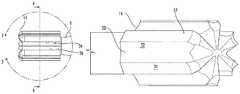
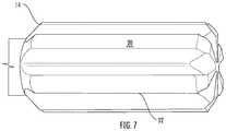
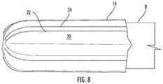
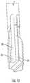
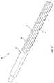
- the first end 8 of the shank 2includes a cutter 14 , the cutter including an outside diameter 16 ; the cutter 14 including two or more flutes 18 , each flute 18 extending parallel to the longitudinal axis 4 and extending inward from the outside diameter 16 toward the longitudinal axis 4 , forming a recessed flute channel 20 ; each flute channel 20 having a pair of opposing sidewalls 22 , 24 and a cylindrical radius at the base of each flute.
- Each sidewallforms a face 26 of a cutting edge 42 extending along the length of each flute channel 20 so that each flute channel 20 provides two opposing faces 26 providing cutting edges 42 , allowing the cutter to cut in both directions when rotationally oscillated around the longitudinal axis 4 .
Landscapes
- Health & Medical Sciences (AREA)
- Life Sciences & Earth Sciences (AREA)
- Surgery (AREA)
- Engineering & Computer Science (AREA)
- Medical Informatics (AREA)
- Veterinary Medicine (AREA)
- Biomedical Technology (AREA)
- Heart & Thoracic Surgery (AREA)
- Nuclear Medicine, Radiotherapy & Molecular Imaging (AREA)
- Molecular Biology (AREA)
- Animal Behavior & Ethology (AREA)
- General Health & Medical Sciences (AREA)
- Public Health (AREA)
- Dentistry (AREA)
- Orthopedic Medicine & Surgery (AREA)
- Oral & Maxillofacial Surgery (AREA)
- Mechanical Engineering (AREA)
- Surgical Instruments (AREA)
Abstract
Description
Claims (17)
Priority Applications (7)
| Application Number | Priority Date | Filing Date | Title |
|---|---|---|---|
| US15/928,885US10582933B2 (en) | 2018-03-22 | 2018-03-22 | Oscillating surgical cutting tool |
| AU2018264064AAU2018264064A1 (en) | 2018-03-22 | 2018-11-12 | Oscillating surgical cutting tool |
| CN201811340348.XACN110292415B (en) | 2018-03-22 | 2018-11-12 | Vibrating surgical cutting tools |
| EP18205734.9AEP3542741B1 (en) | 2018-03-22 | 2018-11-12 | Oscillating surgical cutting tool |
| CA3023868ACA3023868A1 (en) | 2018-03-22 | 2018-11-13 | Oscillating surgical cutting tool |
| US16/773,564US11766266B2 (en) | 2018-03-22 | 2020-01-27 | Oscillating surgical cutting tool |
| US18/454,135US20240041473A1 (en) | 2018-03-22 | 2023-08-23 | Oscillating surgical cutting tool |
Applications Claiming Priority (1)
| Application Number | Priority Date | Filing Date | Title |
|---|---|---|---|
| US15/928,885US10582933B2 (en) | 2018-03-22 | 2018-03-22 | Oscillating surgical cutting tool |
Related Child Applications (1)
| Application Number | Title | Priority Date | Filing Date |
|---|---|---|---|
| US16/773,564ContinuationUS11766266B2 (en) | 2018-03-22 | 2020-01-27 | Oscillating surgical cutting tool |
Publications (2)
| Publication Number | Publication Date |
|---|---|
| US20190290290A1 US20190290290A1 (en) | 2019-09-26 |
| US10582933B2true US10582933B2 (en) | 2020-03-10 |
Family
ID=64559432
Family Applications (3)
| Application Number | Title | Priority Date | Filing Date |
|---|---|---|---|
| US15/928,885Active2038-09-04US10582933B2 (en) | 2018-03-22 | 2018-03-22 | Oscillating surgical cutting tool |
| US16/773,564Active2040-03-11US11766266B2 (en) | 2018-03-22 | 2020-01-27 | Oscillating surgical cutting tool |
| US18/454,135PendingUS20240041473A1 (en) | 2018-03-22 | 2023-08-23 | Oscillating surgical cutting tool |
Family Applications After (2)
| Application Number | Title | Priority Date | Filing Date |
|---|---|---|---|
| US16/773,564Active2040-03-11US11766266B2 (en) | 2018-03-22 | 2020-01-27 | Oscillating surgical cutting tool |
| US18/454,135PendingUS20240041473A1 (en) | 2018-03-22 | 2023-08-23 | Oscillating surgical cutting tool |
Country Status (5)
| Country | Link |
|---|---|
| US (3) | US10582933B2 (en) |
| EP (1) | EP3542741B1 (en) |
| CN (1) | CN110292415B (en) |
| AU (1) | AU2018264064A1 (en) |
| CA (1) | CA3023868A1 (en) |
Cited By (3)
| Publication number | Priority date | Publication date | Assignee | Title |
|---|---|---|---|---|
| USD915591S1 (en)* | 2019-01-25 | 2021-04-06 | Beijing Smtp Technology Co., Ltd. | Ultrasonic cutter head for medical purpose |
| US20240041474A1 (en)* | 2020-12-11 | 2024-02-08 | Stryker European Operations Limited | Surgical Cutting Tool Having A Plurality Of Protuberances And Method Of Manufacturing The Same |
| US20250127522A1 (en)* | 2023-10-24 | 2025-04-24 | Medtronic Ps Medical, Inc. | Surgical bur with improved cutting and method of improving cutting effectiveness |
Families Citing this family (8)
| Publication number | Priority date | Publication date | Assignee | Title |
|---|---|---|---|---|
| USD884172S1 (en)* | 2018-01-12 | 2020-05-12 | Peter L. Bono | Surgical cutting tool |
| USD882792S1 (en)* | 2018-01-31 | 2020-04-28 | Beijing Smtp Technology Co., Ltd. | Ultrasonic cutter head with slotting umbrella |
| US10582933B2 (en) | 2018-03-22 | 2020-03-10 | Capstone Surgical Techologies, LLC | Oscillating surgical cutting tool |
| CN112155676B (en)* | 2020-09-02 | 2025-09-05 | 深圳核心医疗科技股份有限公司 | Surgical opening device |
| US12096946B2 (en)* | 2021-01-28 | 2024-09-24 | Globus Medical, Inc. | Vertebral disc cutter and method |
| US20220330994A1 (en)* | 2021-03-30 | 2022-10-20 | Globus Medical, Inc. | Bi-directional drill point screw |
| CN113857780A (en)* | 2021-07-20 | 2021-12-31 | 宋国俊 | Machining method of reaming tool for minimally invasive surgery |
| US20240156470A1 (en)* | 2022-11-16 | 2024-05-16 | Medtronic Ps Medical, Inc. | Oscillating surgical bone removal tool with fluted cutting head |
Citations (67)
| Publication number | Priority date | Publication date | Assignee | Title |
|---|---|---|---|---|
| US1154159A (en) | 1915-07-12 | 1915-09-21 | Asa Ashworth | Bit for valve-grinders. |
| DE570977C (en) | 1931-10-09 | 1933-02-22 | Wilhelm Ludowici Dr Ing | Dining and serving table |
| US1979905A (en)* | 1932-07-02 | 1934-11-06 | Arderne Scott Thesen Ltd | Process and apparatus for the manufacture of moldings and shaped sections from fiberboards, wood pulp boards, crushed cane boards, beaver boards, and the like |
| US2029114A (en)* | 1934-12-07 | 1936-01-28 | Milne William | Stone saw |
| US2557429A (en) | 1949-10-28 | 1951-06-19 | Zimmer Mfg Company | Surgical bone saw drive |
| US2659398A (en)* | 1951-06-08 | 1953-11-17 | Hervey G Marvin | Kerf planing saw |
| US2795247A (en)* | 1954-07-07 | 1957-06-11 | Skil Corp | Reversible circular saw |
| US2815746A (en)* | 1957-04-10 | 1957-12-10 | Cons Diamond Tool Corp | Cut-off blades for abrasive bodies and their production |
| US2831295A (en) | 1955-09-21 | 1958-04-22 | Gulton Ind Inc | Ultrasonic drill |
| US3064399A (en)* | 1958-08-04 | 1962-11-20 | Norton Co | Diamond cut-off wheel |
| US3128755A (en)* | 1962-10-01 | 1964-04-14 | Vanguard Abrasive Corp | Undercut resistant diamond abrasive saw blade |
| US3203140A (en)* | 1962-02-22 | 1965-08-31 | Diamant Boart Sa | Cutting disc with diamonded segments |
| US3347289A (en)* | 1961-04-05 | 1967-10-17 | Vyzk A Vyv Ustav Drevardsky | Apparatus for rip sawing of logs and timbers |
| US3577579A (en) | 1969-10-29 | 1971-05-04 | John P Duve | Electric toothbrush |
| US3657845A (en)* | 1969-06-14 | 1972-04-25 | Shinji Sekiya | Resinoid pocketed cutoff and grinding wheel and method of making same |
| US3937222A (en)* | 1973-11-09 | 1976-02-10 | Surgical Design Corporation | Surgical instrument employing cutter means |
| US4081704A (en) | 1976-02-13 | 1978-03-28 | Skil Corporation | Powered hand-held tool with unitary sub-assembly mounted by the tool housing sections |
| BE861446A (en) | 1976-12-22 | 1978-03-31 | Leuenberger Roland | PROCESS FOR DRILLING HARD PARTS, IN SURGERY, AND APPARATUS FOR ITS IMPLEMENTATION |
| JPS5613462A (en) | 1979-07-10 | 1981-02-09 | Sumitomo Metal Ind Ltd | Line pipe steel with superior hydrogen sulfide crack resistance |
| US4267814A (en)* | 1979-12-06 | 1981-05-19 | Federal-Mogul Corporation | Abrasive saw blade for trapezoidal grooving |
| JPS5826771B2 (en) | 1979-07-03 | 1983-06-04 | ユリイ イグナテイエビツチ ドドノフ | Magnetron type microwave device |
| US4461198A (en)* | 1980-04-30 | 1984-07-24 | Grassmann Guenther | Sawblade |
| EP0148304A1 (en) | 1984-01-12 | 1985-07-17 | Storz, Karl, Dr.med. h.c. | Operating instrument with an ultrasonic drill probe |
| US4550708A (en)* | 1983-07-06 | 1985-11-05 | Federal-Mogul Corporation | Abrasive cutting wheel for cutting rock-like material |
| US4705017A (en)* | 1985-08-19 | 1987-11-10 | Federal-Mogul Corporation | Stress resistant abrasive cutting wheel |
| US4706659A (en)* | 1984-12-05 | 1987-11-17 | Regents Of The University Of Michigan | Flexible connecting shaft for intramedullary reamer |
| EP0261260A1 (en) | 1986-09-23 | 1988-03-30 | Heinz-Jürgen List | Surgical bone drill |
| US4739745A (en)* | 1985-05-21 | 1988-04-26 | N E D Corp. | Circular diamond saw blade incorporating a novel cutting segment |
| US4854295A (en)* | 1988-06-01 | 1989-08-08 | Federal-Mogul Corporation | Wear resistant abrasive cutting wheel |
| US4932935A (en) | 1986-09-15 | 1990-06-12 | Barry Swartz | Assisted lipectomy device |
| US5018276A (en)* | 1989-05-09 | 1991-05-28 | Kaken Corporation Limited | Tooth structure of rotary saw blade and method of forming the same |
| WO1991007116A1 (en) | 1989-11-14 | 1991-05-30 | Braun Aktiengesellschaft | Electric toothbrush with rotary bristle carrier |
| US5184597A (en)* | 1990-04-27 | 1993-02-09 | Edward Chiuminatta | Apparatus and method for cutting unhardened concrete |
| US5522829A (en) | 1992-04-16 | 1996-06-04 | Arthur D. Little Enterprises, Inc. | Surgical cutting instrument |
| US6015420A (en)* | 1997-03-06 | 2000-01-18 | Scimed Life Systems, Inc. | Atherectomy device for reducing damage to vessels and/or in-vivo stents |
| US6021538A (en) | 1995-06-24 | 2000-02-08 | Braun Aktiengesellschaft | Brush section for an electric toothbrush |
| US20010005909A1 (en)* | 1999-04-30 | 2001-06-28 | Findlay Thomas R. Findlay Thomas R. | Percutaneous material removal device tip |
| US6321738B1 (en)* | 1998-08-28 | 2001-11-27 | Diamond Products Joint Venture | Diamond saw blade |
| WO2002015799A1 (en) | 2000-08-25 | 2002-02-28 | Nanxiang Gao | Sternum cutting apparatus |
| CN1338910A (en) | 1999-02-02 | 2002-03-06 | 库尔斯恩蒂斯股份公司 | Device for removing bone grafts |
| US6422229B1 (en)* | 2000-06-29 | 2002-07-23 | Advanced Micro Devices, Inc. | Saw blade for cutting integrated circuit package boards |
| US20020194975A1 (en)* | 2001-06-08 | 2002-12-26 | Bishop Ralph Carl | Saw blades with tiers of teeth |
| US20040050603A1 (en) | 2000-02-23 | 2004-03-18 | Jaeger Eduard A. | Mounting arrangement for vehicle power source |
| US6721986B2 (en) | 2001-06-28 | 2004-04-20 | Qingping Zhuan | Electric toothbrush |
| CA2513071A1 (en) | 2003-01-09 | 2004-07-29 | Synthes (U.S.A.) | Device for converting a rotary motion into an oscillating motion |
| CN2629654Y (en) | 2003-06-19 | 2004-08-04 | 北京茵普兰人工关节有限公司 | Portable cutting tool for operation |
| US6790215B2 (en)* | 1999-04-30 | 2004-09-14 | Edwards Lifesciences Corporation | Method of use for percutaneous material removal device and tip |
| US6878051B2 (en)* | 2003-02-05 | 2005-04-12 | Saint-Gobain Abrasives Technology Company | Saw blade with shaped gullets |
| US20060130622A1 (en)* | 2004-12-22 | 2006-06-22 | 3M Innovative Properties Company | Circular blade and methods for using same |
| EP1690649A1 (en) | 2005-02-10 | 2006-08-16 | Makita Corporation | Power tool |
| US20060229624A1 (en) | 2005-03-31 | 2006-10-12 | Zimmer Technology, Inc. | Orthopaedic cutting instrument and method |
| WO2007008703A2 (en) | 2005-07-08 | 2007-01-18 | Conceptual Gray, Llc | Apparatus and method thereof for drilling holes in discrete controlled increments |
| GB2430396A (en) | 2005-09-23 | 2007-03-28 | Thomas Hoogland | A surgical drill |
| KR20070119513A (en) | 2006-06-14 | 2007-12-20 | 브루그 로드 아게, 홀딩 | Heat insulation pipe |
| US20080108010A1 (en) | 2006-11-07 | 2008-05-08 | Wen-Hao Wang | Illuminator for a dental drill |
| WO2009151926A2 (en) | 2008-05-23 | 2009-12-17 | Spine View, Inc. | Method and devices for treating spinal stenosis |
| US20110015635A1 (en) | 2009-07-17 | 2011-01-20 | Aryan Henry E | Apparatus and method for facilitating intervertebral arthrodesis and disc space preparation as part of treatment of spinal degenerative disease |
| US20110196404A1 (en) | 2010-02-11 | 2011-08-11 | Ethicon Endo-Surgery, Inc. | Ultrasonic surgical instruments with moving cutting implement |
| US8007506B2 (en)* | 2006-06-30 | 2011-08-30 | Atheromed, Inc. | Atherectomy devices and methods |
| US20110295270A1 (en) | 2007-01-10 | 2011-12-01 | Ethicon Endo-Surgery, Inc. | Surgical instrument with wireless communication between a control unit of a robotic system and remote sensor |
| US20130245629A1 (en) | 2012-03-14 | 2013-09-19 | Stryker Corporation | Surgical drill with drive shaft and drill bit that, after disengaging the drill bit from the drive shaft, allows the drill bit to be driven in reverse |
| WO2014150514A1 (en) | 2013-03-15 | 2014-09-25 | Misonix, Incorporated | Ultrasonic surgical drill and associated surgical method |
| WO2015006296A1 (en) | 2013-07-09 | 2015-01-15 | Stryker Corporation | Surgical drill having brake that, upon the drill bit penetrating through bone, prevents further insertion of the drill bit |
| US8943634B2 (en) | 2011-05-02 | 2015-02-03 | Water Pik, Inc. | Mechanically-driven, sonic toothbrush system |
| US20150135915A1 (en)* | 2013-11-15 | 2015-05-21 | C. & E. Fein Gmbh | Saw Blade For An Oscillatingly Driven Saw |
| US20170231643A1 (en)* | 2016-02-12 | 2017-08-17 | Greatbatch Ltd. | Cutting heads for intramedullary reamers |
| US20180042618A1 (en)* | 2016-08-14 | 2018-02-15 | Greatbatch Ltd. | Cutting head for an intramedullary reamer |
Family Cites Families (54)
| Publication number | Priority date | Publication date | Assignee | Title |
|---|---|---|---|---|
| US2834158A (en) | 1955-01-28 | 1958-05-13 | Gulton Ind Inc | Ultrasonic drill |
| US2825186A (en) | 1956-02-27 | 1958-03-04 | Gulton Ind Inc | Ultrasonic drill |
| US3058199A (en)* | 1960-05-26 | 1962-10-16 | Dixie Tool Ind Inc | Cutting tool |
| GB1170845A (en) | 1967-08-11 | 1969-11-19 | Derouter Brothers Ltd | Improved Portable Power Operated Saw |
| DE2427716B1 (en) | 1974-06-08 | 1975-11-13 | Paul Dr Brinckmann | Bone saws for medical purposes |
| SE7707082L (en)* | 1976-07-06 | 1978-01-07 | Scheicher Hans | DRILLING HEAD AND BONE DRILL, IN PARTICULAR FOR THE PREPARATION OF BENCH CAVITES FOR RECEIVING ENOSSAL PROTETICAL ELEMENTS, AND AN ENOSSAL ODONTOLOGICAL HALF IMPLANT |
| USD262630S (en) | 1979-01-19 | 1982-01-12 | Robert W. Lee | Drill bit |
| JPS5826771U (en) | 1981-08-10 | 1983-02-21 | ソニー株式会社 | Cassette ejection mechanism in recording/playback equipment |
| US4596243A (en) | 1983-05-25 | 1986-06-24 | Bray Robert S | Surgical methods and apparatus for bone removal |
| US4556347A (en) | 1984-05-11 | 1985-12-03 | Lockheed Corporation | Split-point twist drill |
| US5092875A (en) | 1990-04-30 | 1992-03-03 | Mclees Donald J | Bone saw for tendon transplant surgery |
| WO1993025151A1 (en) | 1992-06-12 | 1993-12-23 | Larry Steven Nichter | Wire driver and method |
| US5269355A (en)* | 1992-09-08 | 1993-12-14 | Bowen Randal G | Cutting wheel for stump-grinding apparatus |
| SE508466C2 (en) | 1993-09-14 | 1998-10-12 | Seco Tools Ab | Drill |
| US5626444A (en)* | 1994-03-09 | 1997-05-06 | Campian; Jonathon | Rotary cutting tool |
| US5728118A (en) | 1995-03-29 | 1998-03-17 | Linvatec Corporation | Apparatus and method for harvesting a bone-tendon-bone ligament graft |
| US7540875B2 (en) | 1998-06-01 | 2009-06-02 | Avatar Design & Development, Inc. | Surgical cutting tool with automatically retractable blade assembly |
| US6083228A (en) | 1998-06-09 | 2000-07-04 | Michelson; Gary K. | Device and method for preparing a space between adjacent vertebrae to receive an insert |
| EP1681021A3 (en) | 1998-06-09 | 2009-04-15 | Warsaw Orthopedic, Inc. | Abrading element for preparing a space between adjacent vertebral bodies |
| US6267542B1 (en) | 1999-01-15 | 2001-07-31 | Avraham Salmon | Drill bit having a chiseless bit tip |
| US6234725B1 (en)* | 1999-12-14 | 2001-05-22 | Jonathan R. Campian | Rotary cutting tool |
| US7387612B2 (en) | 2001-03-28 | 2008-06-17 | Cybersonics, Inc. | Floating probe for ultrasonic transducers |
| US6498421B1 (en) | 2001-06-15 | 2002-12-24 | Amega Lab, L.L.C. | Ultrasonic drilling device with arc-shaped probe |
| US20030204199A1 (en) | 2002-04-30 | 2003-10-30 | Novak Theodore A. D. | Device and method for ultrasonic tissue excision with tissue selectivity |
| DE10243104A1 (en) | 2002-09-17 | 2004-03-25 | Gebr. Brasseler Gmbh & Co. Kg | Rotating ceramic tool with a ceramic cutting head bonded to a ceramic or metal support shaft |
| US20040147934A1 (en) | 2002-10-18 | 2004-07-29 | Kiester P. Douglas | Oscillating, steerable, surgical burring tool and method of using the same |
| US6899685B2 (en) | 2003-01-24 | 2005-05-31 | Acueity, Inc. | Biopsy device |
| US7090442B2 (en) | 2003-12-09 | 2006-08-15 | The Boeing Company | Shaper router and method |
| ATE441376T1 (en) | 2003-12-17 | 2009-09-15 | Depuy Spine Inc | INSTRUMENTS AND PROCEDURES FOR BONE ANCHOR PROCEDURES AND SPINAL BAR REDUCTION |
| US7842044B2 (en) | 2003-12-17 | 2010-11-30 | Depuy Spine, Inc. | Instruments and methods for bone anchor engagement and spinal rod reduction |
| US8025662B2 (en) | 2004-03-25 | 2011-09-27 | Symmetry Medical, Inc. | Bidirectional reaming cutter |
| US8092475B2 (en) | 2005-04-15 | 2012-01-10 | Integra Lifesciences (Ireland) Ltd. | Ultrasonic horn for removal of hard tissue |
| US8142460B2 (en) | 2005-04-15 | 2012-03-27 | Integra Lifesciences (Ireland) Ltd. | Bone abrading ultrasonic horns |
| US8282661B2 (en)* | 2005-06-06 | 2012-10-09 | Concept Matrix, Llc | Multi-blade curette tool |
| KR20070019513A (en) | 2005-10-26 | 2007-02-15 | 김용철 | Easy to assemble metal balls |
| US8465491B2 (en) | 2006-06-01 | 2013-06-18 | Osteo Innovations Llc | Bone drill |
| US8480673B2 (en) | 2006-06-01 | 2013-07-09 | Osteo Innovations Llc | Cavity creation device and methods of use |
| WO2008103606A2 (en) | 2007-02-20 | 2008-08-28 | Gabriel Institute, Inc. | Bone drill and methods of treatment delivery |
| MX2009010707A (en) | 2007-04-04 | 2010-03-26 | Alexandria Res Technologies Llc | Apparatus and method for sculpting the surface of a joint. |
| US8353912B2 (en) | 2007-06-01 | 2013-01-15 | Misonix, Incorporated | Ultrasonic spinal surgery method |
| US20090024129A1 (en) | 2007-07-19 | 2009-01-22 | Jeremy Gordon | Perforator with inner and outer drills and a drive head, the inner drill configured to move against the outer drill in order to disengage from the drive head |
| GB0809494D0 (en)* | 2008-05-23 | 2008-07-02 | Osteocare Internat Ltd | A drill bit for use in surgery |
| US20110184447A1 (en) | 2010-01-26 | 2011-07-28 | Warsaw Orthopedic, Inc. | Surgical cutting tool and method |
| US8951272B2 (en)* | 2010-02-11 | 2015-02-10 | Ethicon Endo-Surgery, Inc. | Seal arrangements for ultrasonically powered surgical instruments |
| US20110319895A1 (en)* | 2010-06-25 | 2011-12-29 | Depuy Mitek, Inc. | Fluted bone awl and method of use |
| TWI494076B (en) | 2011-04-18 | 2015-08-01 | Univ Nat Central | Medical drill |
| EP2750862B1 (en)* | 2011-09-01 | 2016-07-06 | Covidien LP | Catheter with helical drive shaft and methods of manufacture |
| US9232952B2 (en)* | 2012-04-16 | 2016-01-12 | Medtronic Ps Medical, Inc. | Surgical bur with non-paired flutes |
| US9232953B2 (en) | 2012-10-08 | 2016-01-12 | Peter Bono | Cutting tool for bone, cartilage, and disk removal |
| US20140150620A1 (en)* | 2012-11-30 | 2014-06-05 | Irwin Industrial Tool Company | Saw Blade Having Different Material Teeth and Method of Manufacture |
| EP3035871B1 (en) | 2013-08-21 | 2019-05-29 | Michael J. Scianamblo | Bone drill |
| USD779670S1 (en) | 2015-06-15 | 2017-02-21 | Echo Therapeutics, Inc. | Abrasion device with abrasive tip |
| USD800903S1 (en) | 2016-02-09 | 2017-10-24 | Medtronic Ps Medical, Inc. | Surgical tool |
| US10582933B2 (en) | 2018-03-22 | 2020-03-10 | Capstone Surgical Techologies, LLC | Oscillating surgical cutting tool |
- 2018
- 2018-03-22USUS15/928,885patent/US10582933B2/enactiveActive
- 2018-11-12AUAU2018264064Apatent/AU2018264064A1/ennot_activeAbandoned
- 2018-11-12CNCN201811340348.XApatent/CN110292415B/enactiveActive
- 2018-11-12EPEP18205734.9Apatent/EP3542741B1/enactiveActive
- 2018-11-13CACA3023868Apatent/CA3023868A1/enactivePending
- 2020
- 2020-01-27USUS16/773,564patent/US11766266B2/enactiveActive
- 2023
- 2023-08-23USUS18/454,135patent/US20240041473A1/enactivePending
Patent Citations (105)
| Publication number | Priority date | Publication date | Assignee | Title |
|---|---|---|---|---|
| US1154159A (en) | 1915-07-12 | 1915-09-21 | Asa Ashworth | Bit for valve-grinders. |
| DE570977C (en) | 1931-10-09 | 1933-02-22 | Wilhelm Ludowici Dr Ing | Dining and serving table |
| US1979905A (en)* | 1932-07-02 | 1934-11-06 | Arderne Scott Thesen Ltd | Process and apparatus for the manufacture of moldings and shaped sections from fiberboards, wood pulp boards, crushed cane boards, beaver boards, and the like |
| US2029114A (en)* | 1934-12-07 | 1936-01-28 | Milne William | Stone saw |
| US2557429A (en) | 1949-10-28 | 1951-06-19 | Zimmer Mfg Company | Surgical bone saw drive |
| US2659398A (en)* | 1951-06-08 | 1953-11-17 | Hervey G Marvin | Kerf planing saw |
| US2795247A (en)* | 1954-07-07 | 1957-06-11 | Skil Corp | Reversible circular saw |
| US2831295A (en) | 1955-09-21 | 1958-04-22 | Gulton Ind Inc | Ultrasonic drill |
| US2815746A (en)* | 1957-04-10 | 1957-12-10 | Cons Diamond Tool Corp | Cut-off blades for abrasive bodies and their production |
| US3064399A (en)* | 1958-08-04 | 1962-11-20 | Norton Co | Diamond cut-off wheel |
| US3347289A (en)* | 1961-04-05 | 1967-10-17 | Vyzk A Vyv Ustav Drevardsky | Apparatus for rip sawing of logs and timbers |
| US3203140A (en)* | 1962-02-22 | 1965-08-31 | Diamant Boart Sa | Cutting disc with diamonded segments |
| US3128755A (en)* | 1962-10-01 | 1964-04-14 | Vanguard Abrasive Corp | Undercut resistant diamond abrasive saw blade |
| US3657845A (en)* | 1969-06-14 | 1972-04-25 | Shinji Sekiya | Resinoid pocketed cutoff and grinding wheel and method of making same |
| US3577579A (en) | 1969-10-29 | 1971-05-04 | John P Duve | Electric toothbrush |
| US3937222A (en)* | 1973-11-09 | 1976-02-10 | Surgical Design Corporation | Surgical instrument employing cutter means |
| US4081704A (en) | 1976-02-13 | 1978-03-28 | Skil Corporation | Powered hand-held tool with unitary sub-assembly mounted by the tool housing sections |
| GB1550577A (en) | 1976-12-22 | 1979-08-15 | Leuenberger Roland | Methods of and apparatus for surgical drilling |
| BE861446A (en) | 1976-12-22 | 1978-03-31 | Leuenberger Roland | PROCESS FOR DRILLING HARD PARTS, IN SURGERY, AND APPARATUS FOR ITS IMPLEMENTATION |
| FI773650A7 (en) | 1976-12-22 | 1978-06-23 | Roland Leuenberger | FOERFARANDE FOER BORRANDE AV HAOL I HAORDA AEMNEN FOER KIRURGISKA AENDAMAOL OCH ANORDNING FOER GENOMFOERANDE AV FOERFARANDE |
| NL7713563A (en) | 1976-12-22 | 1978-06-26 | Leuenberger Roland | PROCEDURE FOR DRILLING HOLES IN HARD MATERIALS DURING OPERATIONS AND THE EQUIPMENT THEREOF. |
| DE2730227A1 (en) | 1976-12-22 | 1978-06-29 | Roland Leuenberger | DEVICE FOR PROCESSING HARD BODY PARTS, IN PARTICULAR BONES |
| JPS5380789A (en) | 1976-12-22 | 1978-07-17 | Leuenberger Roland | Method of and device for perforating hard material by surgical treatment |
| FR2374886A1 (en) | 1976-12-22 | 1978-07-21 | Leuenberger Roland | PROCESS FOR DRILLING HARD PARTS, IN SURGERY, AND APPARATUS FOR ITS IMPLEMENTATION |
| US4111208A (en) | 1976-12-22 | 1978-09-05 | Roland Leuenberger | Process for drilling holes in hard materials, in surgical procedures, and apparatus for carrying out the process |
| CH610753A5 (en) | 1976-12-22 | 1979-05-15 | Roland Leuenberger | |
| NO774411L (en) | 1976-12-22 | 1978-06-23 | Roland Leuenberger | PROCEDURE FOR DRILLING HOLES IN HARD MATERIALS FOR SURGICAL INTERVENTIONS AND APPARATUS FOR ITS PERFORMANCE |
| ES465719A1 (en) | 1976-12-22 | 1980-12-16 | Leuenberger Roland | Process for drilling holes in hard materials, in surgical procedures, and apparatus for carrying out the process |
| IT1081824B (en) | 1976-12-22 | 1985-05-21 | Leuenberger Roland | PARTIDURE DRILLING PROCEDURE, AND APPARATUS FOR ITS REALIZATION |
| AT370608B (en) | 1976-12-22 | 1983-04-25 | Leuenberger Roland | DEVICE FOR DRILLING HARD PARTS IN SURGERY |
| CA1112970A (en) | 1976-12-22 | 1981-11-24 | Roland Leuenberger | Process for drilling holes in hard material in surgical procedures, and apparatus for carrying out the process |
| JPS5826771B2 (en) | 1979-07-03 | 1983-06-04 | ユリイ イグナテイエビツチ ドドノフ | Magnetron type microwave device |
| JPS5613462A (en) | 1979-07-10 | 1981-02-09 | Sumitomo Metal Ind Ltd | Line pipe steel with superior hydrogen sulfide crack resistance |
| US4267814A (en)* | 1979-12-06 | 1981-05-19 | Federal-Mogul Corporation | Abrasive saw blade for trapezoidal grooving |
| US4461198A (en)* | 1980-04-30 | 1984-07-24 | Grassmann Guenther | Sawblade |
| US4550708A (en)* | 1983-07-06 | 1985-11-05 | Federal-Mogul Corporation | Abrasive cutting wheel for cutting rock-like material |
| EP0148304A1 (en) | 1984-01-12 | 1985-07-17 | Storz, Karl, Dr.med. h.c. | Operating instrument with an ultrasonic drill probe |
| US4706659A (en)* | 1984-12-05 | 1987-11-17 | Regents Of The University Of Michigan | Flexible connecting shaft for intramedullary reamer |
| US4739745A (en)* | 1985-05-21 | 1988-04-26 | N E D Corp. | Circular diamond saw blade incorporating a novel cutting segment |
| US4705017A (en)* | 1985-08-19 | 1987-11-10 | Federal-Mogul Corporation | Stress resistant abrasive cutting wheel |
| US4932935A (en) | 1986-09-15 | 1990-06-12 | Barry Swartz | Assisted lipectomy device |
| EP0261260A1 (en) | 1986-09-23 | 1988-03-30 | Heinz-Jürgen List | Surgical bone drill |
| US4854295A (en)* | 1988-06-01 | 1989-08-08 | Federal-Mogul Corporation | Wear resistant abrasive cutting wheel |
| US5018276A (en)* | 1989-05-09 | 1991-05-28 | Kaken Corporation Limited | Tooth structure of rotary saw blade and method of forming the same |
| WO1991007116A1 (en) | 1989-11-14 | 1991-05-30 | Braun Aktiengesellschaft | Electric toothbrush with rotary bristle carrier |
| US5184597A (en)* | 1990-04-27 | 1993-02-09 | Edward Chiuminatta | Apparatus and method for cutting unhardened concrete |
| US5522829A (en) | 1992-04-16 | 1996-06-04 | Arthur D. Little Enterprises, Inc. | Surgical cutting instrument |
| US6021538A (en) | 1995-06-24 | 2000-02-08 | Braun Aktiengesellschaft | Brush section for an electric toothbrush |
| US6015420A (en)* | 1997-03-06 | 2000-01-18 | Scimed Life Systems, Inc. | Atherectomy device for reducing damage to vessels and/or in-vivo stents |
| US6321738B1 (en)* | 1998-08-28 | 2001-11-27 | Diamond Products Joint Venture | Diamond saw blade |
| CN1338910A (en) | 1999-02-02 | 2002-03-06 | 库尔斯恩蒂斯股份公司 | Device for removing bone grafts |
| US20010005909A1 (en)* | 1999-04-30 | 2001-06-28 | Findlay Thomas R. Findlay Thomas R. | Percutaneous material removal device tip |
| US6790215B2 (en)* | 1999-04-30 | 2004-09-14 | Edwards Lifesciences Corporation | Method of use for percutaneous material removal device and tip |
| US20040050603A1 (en) | 2000-02-23 | 2004-03-18 | Jaeger Eduard A. | Mounting arrangement for vehicle power source |
| US6422229B1 (en)* | 2000-06-29 | 2002-07-23 | Advanced Micro Devices, Inc. | Saw blade for cutting integrated circuit package boards |
| WO2002015799A1 (en) | 2000-08-25 | 2002-02-28 | Nanxiang Gao | Sternum cutting apparatus |
| US20020194975A1 (en)* | 2001-06-08 | 2002-12-26 | Bishop Ralph Carl | Saw blades with tiers of teeth |
| US6721986B2 (en) | 2001-06-28 | 2004-04-20 | Qingping Zhuan | Electric toothbrush |
| EP1581374A1 (en) | 2003-01-09 | 2005-10-05 | SYNTHES AG Chur | Device for translating a rotational motion into an oscillating motion |
| JP2006512954A (en) | 2003-01-09 | 2006-04-20 | ジンテーズ アクチエンゲゼルシャフト クール | A device that converts rotational motion into vibration |
| AU2003200831A1 (en) | 2003-01-09 | 2004-08-10 | Synthes Gmbh | Device for translating a rotational motion into an oscillating motion |
| WO2004062863A1 (en) | 2003-01-09 | 2004-07-29 | Synthes Ag Chur | Device for translating a rotational motion into an oscillating motion |
| CL2004000025A1 (en) | 2003-01-09 | 2005-03-18 | Synthes Gmbh | DEVICE FOR TRANSFORMING A ROTATING MOVEMENT IN AN OSCILLATING MOVEMENT APPLICABLE TO A SURGICAL DEVICE FOR SAWING BONES, IS FORMED BY A FIRST ROTATING TREE AND A SECOND OSCILLATING TREE WITH COAXIAL LONGITUDINAL AXES, AND A |
| JP4481173B2 (en) | 2003-01-09 | 2010-06-16 | ジンテーズ ゲゼルシャフト ミト ベシュレンクテル ハフツング | A device that converts rotational motion into vibration |
| AR042807A1 (en) | 2003-01-09 | 2005-07-06 | Synthes Ag | DEVICE FOR TRANSFORMING A ROTATING MOVEMENT IN AN OSCILLATING ROTATING MOVEMENT |
| CA2513071A1 (en) | 2003-01-09 | 2004-07-29 | Synthes (U.S.A.) | Device for converting a rotary motion into an oscillating motion |
| US20050283175A1 (en) | 2003-01-09 | 2005-12-22 | Peter Tanner | Device for converting a rotary motion into an oscillating motion |
| US6878051B2 (en)* | 2003-02-05 | 2005-04-12 | Saint-Gobain Abrasives Technology Company | Saw blade with shaped gullets |
| CN2629654Y (en) | 2003-06-19 | 2004-08-04 | 北京茵普兰人工关节有限公司 | Portable cutting tool for operation |
| US20060130622A1 (en)* | 2004-12-22 | 2006-06-22 | 3M Innovative Properties Company | Circular blade and methods for using same |
| EP1690649A1 (en) | 2005-02-10 | 2006-08-16 | Makita Corporation | Power tool |
| US20060229624A1 (en) | 2005-03-31 | 2006-10-12 | Zimmer Technology, Inc. | Orthopaedic cutting instrument and method |
| US7922720B2 (en) | 2005-03-31 | 2011-04-12 | Zimmer Technology, Inc. | Orthopaedic cutting instrument and method |
| US20090177202A1 (en) | 2005-03-31 | 2009-07-09 | Zimmer Technology, Inc. | Orthopaedic cutting instrument and method |
| WO2007008703A2 (en) | 2005-07-08 | 2007-01-18 | Conceptual Gray, Llc | Apparatus and method thereof for drilling holes in discrete controlled increments |
| CN101267774A (en) | 2005-09-23 | 2008-09-17 | 霍格兰德·托马斯 | Surgical drill, surgical drill set, system for cutting bone and method for removing bone |
| KR20080070631A (en) | 2005-09-23 | 2008-07-30 | 토마스 후그란드 | Surgical drills, surgical drill sets, bone cutting systems and bone removal methods |
| KR101333472B1 (en) | 2005-09-23 | 2013-11-26 | 토마스 후그란드 | A surgical drill, a set of surgical drills, a system for cutting bone and a method for removing bone |
| WO2007039141A2 (en) | 2005-09-23 | 2007-04-12 | Thomas Hoogland | A surgical drill, a set of surgical drills, a system for cutting bone and a method for removing bone |
| EP1937160A2 (en) | 2005-09-23 | 2008-07-02 | Thomas Hoogland | A surgical drill, a set of surgical drills, a system for cutting bone and a method for removing bone |
| GB2430396A (en) | 2005-09-23 | 2007-03-28 | Thomas Hoogland | A surgical drill |
| KR20070119513A (en) | 2006-06-14 | 2007-12-20 | 브루그 로드 아게, 홀딩 | Heat insulation pipe |
| US8007506B2 (en)* | 2006-06-30 | 2011-08-30 | Atheromed, Inc. | Atherectomy devices and methods |
| US20080108010A1 (en) | 2006-11-07 | 2008-05-08 | Wen-Hao Wang | Illuminator for a dental drill |
| US20120211546A1 (en) | 2007-01-10 | 2012-08-23 | Ethicon Endo-Surgery, Inc. | Drive interface for operably coupling a manipulatable surgical tool to a robot |
| US20110295270A1 (en) | 2007-01-10 | 2011-12-01 | Ethicon Endo-Surgery, Inc. | Surgical instrument with wireless communication between a control unit of a robotic system and remote sensor |
| WO2009151926A2 (en) | 2008-05-23 | 2009-12-17 | Spine View, Inc. | Method and devices for treating spinal stenosis |
| US20110015635A1 (en) | 2009-07-17 | 2011-01-20 | Aryan Henry E | Apparatus and method for facilitating intervertebral arthrodesis and disc space preparation as part of treatment of spinal degenerative disease |
| US20150119916A1 (en) | 2010-02-11 | 2015-04-30 | Ethicon Endo-Surgery, Inc. | Ultrasonic surgical instruments with moving cutting implement |
| WO2011100313A1 (en) | 2010-02-11 | 2011-08-18 | Ethicon Endo-Surgery, Inc. | Ultrasonic surgical instruments with moving cutting implement |
| US20110196404A1 (en) | 2010-02-11 | 2011-08-11 | Ethicon Endo-Surgery, Inc. | Ultrasonic surgical instruments with moving cutting implement |
| CN102781349A (en) | 2010-02-11 | 2012-11-14 | 伊西康内外科公司 | Ultrasonic surgical instruments with moving cutting implement |
| EP2533703A1 (en) | 2010-02-11 | 2012-12-19 | Ethicon Endo-Surgery, Inc. | Ultrasonic surgical instruments with moving cutting implement |
| JP2013519434A (en) | 2010-02-11 | 2013-05-30 | エシコン・エンド−サージェリィ・インコーポレイテッド | Surgical ultrasonic instrument with a driven cutting tool |
| CA2788918A1 (en) | 2010-02-11 | 2011-08-18 | Ethicon Endo-Surgery, Inc. | Ultrasonic surgical instruments with moving cutting implement |
| AU2011215901A1 (en) | 2010-02-11 | 2012-08-16 | Ethicon Endo-Surgery, Inc. | Ultrasonic surgical instruments with moving cutting implement |
| JP5826771B2 (en) | 2010-02-11 | 2015-12-02 | エシコン・エンド−サージェリィ・インコーポレイテッドEthicon Endo−Surgery,Inc. | Surgical ultrasonic instrument with a driven cutting tool |
| US8943634B2 (en) | 2011-05-02 | 2015-02-03 | Water Pik, Inc. | Mechanically-driven, sonic toothbrush system |
| WO2012166476A1 (en) | 2011-05-27 | 2012-12-06 | Ethicon Endo - Surgery, Inc. | Surgical instrument with wireless communication between a control unit of a robotic system and remote sensor |
| US20130245629A1 (en) | 2012-03-14 | 2013-09-19 | Stryker Corporation | Surgical drill with drive shaft and drill bit that, after disengaging the drill bit from the drive shaft, allows the drill bit to be driven in reverse |
| WO2014150514A1 (en) | 2013-03-15 | 2014-09-25 | Misonix, Incorporated | Ultrasonic surgical drill and associated surgical method |
| WO2015006296A1 (en) | 2013-07-09 | 2015-01-15 | Stryker Corporation | Surgical drill having brake that, upon the drill bit penetrating through bone, prevents further insertion of the drill bit |
| US20150135915A1 (en)* | 2013-11-15 | 2015-05-21 | C. & E. Fein Gmbh | Saw Blade For An Oscillatingly Driven Saw |
| US20170231643A1 (en)* | 2016-02-12 | 2017-08-17 | Greatbatch Ltd. | Cutting heads for intramedullary reamers |
| US20180042618A1 (en)* | 2016-08-14 | 2018-02-15 | Greatbatch Ltd. | Cutting head for an intramedullary reamer |
Non-Patent Citations (5)
| Title |
|---|
| Cutting Tool, Drill Bit, End Mill, Internet catalogue, http://lzqtool.com/include/search.aspx?keycode=c-grade&type=1&language=en, (Retrieved Feb. 7, 2018). |
| MasterCut Tool Corp., Bur Series, Metric, (2018). |
| MasterCut Tool Corp., Bur Series, US, (2010). |
| News & Notes, British Dental Journal, vol. 191, No. 7, pp. 410-411 (Oct. 13, 2001). |
| Tungsten Carbide Drills Mills & Burs, Internet catalogue, http://chinatungsten.com/picture-bank/tungsten-carbide-drills.html, (Retrieved Feb. 7, 2018). |
Cited By (3)
| Publication number | Priority date | Publication date | Assignee | Title |
|---|---|---|---|---|
| USD915591S1 (en)* | 2019-01-25 | 2021-04-06 | Beijing Smtp Technology Co., Ltd. | Ultrasonic cutter head for medical purpose |
| US20240041474A1 (en)* | 2020-12-11 | 2024-02-08 | Stryker European Operations Limited | Surgical Cutting Tool Having A Plurality Of Protuberances And Method Of Manufacturing The Same |
| US20250127522A1 (en)* | 2023-10-24 | 2025-04-24 | Medtronic Ps Medical, Inc. | Surgical bur with improved cutting and method of improving cutting effectiveness |
Also Published As
| Publication number | Publication date |
|---|---|
| CN110292415B (en) | 2024-08-06 |
| US20200155167A1 (en) | 2020-05-21 |
| CA3023868A1 (en) | 2019-09-22 |
| US20190290290A1 (en) | 2019-09-26 |
| AU2018264064A1 (en) | 2019-10-10 |
| EP3542741B1 (en) | 2022-07-20 |
| US20240041473A1 (en) | 2024-02-08 |
| CN110292415A (en) | 2019-10-01 |
| US11766266B2 (en) | 2023-09-26 |
| EP3542741A1 (en) | 2019-09-25 |
Similar Documents
| Publication | Publication Date | Title |
|---|---|---|
| US11766266B2 (en) | Oscillating surgical cutting tool | |
| CA2494062C (en) | A drill bit and method for producing a drill bit | |
| CN103025461B (en) | end mill | |
| CA2578787C (en) | Helical flute end mill with multi-section cutting edge | |
| US20060212060A1 (en) | Arthroscopic shaver and method of manufacturing same | |
| JP4261969B2 (en) | Tool for dishing, deburring and / or spindle-shaped holes | |
| JPH1170127A (en) | Stagger cut teeth | |
| JP6359419B2 (en) | drill | |
| JP4620199B2 (en) | Drill with handle with spiral groove to transport chips | |
| RU2004130365A (en) | CERAMIC DRILL FOR HIGH SPEED DRILLING | |
| JP2020506018A5 (en) | ||
| JP6729853B2 (en) | Drill | |
| JPH1043193A (en) | Cutter for bone cutting | |
| HK40014853A (en) | Oscillating surgical cutting tool | |
| HK40014853B (en) | Oscillating surgical cutting tool | |
| JP2003275913A (en) | Drill | |
| JP4370966B2 (en) | Grooved tool | |
| JP2001025912A (en) | Ball end mill | |
| WO2024176439A1 (en) | Drill | |
| JP2009233851A (en) | Grooved tool | |
| JP4610102B2 (en) | Ball end mill | |
| JP3639227B2 (en) | Drilling tools for brittle materials | |
| JP2649015B2 (en) | Drill | |
| JP3754270B2 (en) | Taper blade end mill | |
| JP4206778B2 (en) | Center drill |
Legal Events
| Date | Code | Title | Description |
|---|---|---|---|
| AS | Assignment | Owner name:BONO, PETER L., MICHIGAN Free format text:ASSIGNMENT OF ASSIGNORS INTEREST;ASSIGNORS:BONO, PETER L.;LARK, JAMES D.;SCALES, JOHN S.;REEL/FRAME:045319/0611 Effective date:20180314 | |
| FEPP | Fee payment procedure | Free format text:ENTITY STATUS SET TO UNDISCOUNTED (ORIGINAL EVENT CODE: BIG.); ENTITY STATUS OF PATENT OWNER: SMALL ENTITY | |
| FEPP | Fee payment procedure | Free format text:ENTITY STATUS SET TO SMALL (ORIGINAL EVENT CODE: SMAL); ENTITY STATUS OF PATENT OWNER: SMALL ENTITY | |
| STPP | Information on status: patent application and granting procedure in general | Free format text:DOCKETED NEW CASE - READY FOR EXAMINATION | |
| STPP | Information on status: patent application and granting procedure in general | Free format text:NOTICE OF ALLOWANCE MAILED -- APPLICATION RECEIVED IN OFFICE OF PUBLICATIONS | |
| STPP | Information on status: patent application and granting procedure in general | Free format text:PUBLICATIONS -- ISSUE FEE PAYMENT RECEIVED | |
| STCF | Information on status: patent grant | Free format text:PATENTED CASE | |
| AS | Assignment | Owner name:CAPSTONE SURGICAL TECHNOLOGIES, LLC, MICHIGAN Free format text:ASSIGNMENT OF ASSIGNORS INTEREST;ASSIGNOR:BONO, PETER L.;REEL/FRAME:057844/0893 Effective date:20211013 | |
| AS | Assignment | Owner name:GLOBUS MEDICAL, INC., PENNSYLVANIA Free format text:ASSIGNMENT OF ASSIGNORS INTEREST;ASSIGNOR:CAPSTONE SURGICAL TECHNOLOGIES, LLC;REEL/FRAME:058521/0563 Effective date:20211104 | |
| FEPP | Fee payment procedure | Free format text:ENTITY STATUS SET TO UNDISCOUNTED (ORIGINAL EVENT CODE: BIG.); ENTITY STATUS OF PATENT OWNER: LARGE ENTITY | |
| MAFP | Maintenance fee payment | Free format text:PAYMENT OF MAINTENANCE FEE, 4TH YEAR, LARGE ENTITY (ORIGINAL EVENT CODE: M1551); ENTITY STATUS OF PATENT OWNER: LARGE ENTITY Year of fee payment:4 |