US10581685B2 - Method for automatic tracking of hybrid fiber coaxial upstream service upgrades - Google Patents
Method for automatic tracking of hybrid fiber coaxial upstream service upgradesDownload PDFInfo
- Publication number
- US10581685B2 US10581685B2US14/563,680US201414563680AUS10581685B2US 10581685 B2US10581685 B2US 10581685B2US 201414563680 AUS201414563680 AUS 201414563680AUS 10581685 B2US10581685 B2US 10581685B2
- Authority
- US
- United States
- Prior art keywords
- cpe device
- response
- cpe
- query
- network
- Prior art date
- Legal status (The legal status is an assumption and is not a legal conclusion. Google has not performed a legal analysis and makes no representation as to the accuracy of the status listed.)
- Active
Links
Images


Classifications
- H—ELECTRICITY
- H04—ELECTRIC COMMUNICATION TECHNIQUE
- H04L—TRANSMISSION OF DIGITAL INFORMATION, e.g. TELEGRAPHIC COMMUNICATION
- H04L41/00—Arrangements for maintenance, administration or management of data switching networks, e.g. of packet switching networks
- H04L41/08—Configuration management of networks or network elements
- H04L41/085—Retrieval of network configuration; Tracking network configuration history
- H04L41/0853—Retrieval of network configuration; Tracking network configuration history by actively collecting configuration information or by backing up configuration information
- H—ELECTRICITY
- H04—ELECTRIC COMMUNICATION TECHNIQUE
- H04B—TRANSMISSION
- H04B3/00—Line transmission systems
- H04B3/02—Details
- H04B3/46—Monitoring; Testing
- H—ELECTRICITY
- H04—ELECTRIC COMMUNICATION TECHNIQUE
- H04L—TRANSMISSION OF DIGITAL INFORMATION, e.g. TELEGRAPHIC COMMUNICATION
- H04L12/00—Data switching networks
- H04L12/28—Data switching networks characterised by path configuration, e.g. LAN [Local Area Networks] or WAN [Wide Area Networks]
- H04L12/40—Bus networks
- H04L12/403—Bus networks with centralised control, e.g. polling
- H—ELECTRICITY
- H04—ELECTRIC COMMUNICATION TECHNIQUE
- H04L—TRANSMISSION OF DIGITAL INFORMATION, e.g. TELEGRAPHIC COMMUNICATION
- H04L41/00—Arrangements for maintenance, administration or management of data switching networks, e.g. of packet switching networks
- H04L41/08—Configuration management of networks or network elements
- H04L41/0803—Configuration setting
- H04L41/0813—Configuration setting characterised by the conditions triggering a change of settings
- H04L41/082—Configuration setting characterised by the conditions triggering a change of settings the condition being updates or upgrades of network functionality
- H—ELECTRICITY
- H04—ELECTRIC COMMUNICATION TECHNIQUE
- H04L—TRANSMISSION OF DIGITAL INFORMATION, e.g. TELEGRAPHIC COMMUNICATION
- H04L41/00—Arrangements for maintenance, administration or management of data switching networks, e.g. of packet switching networks
- H04L41/12—Discovery or management of network topologies
- H—ELECTRICITY
- H04—ELECTRIC COMMUNICATION TECHNIQUE
- H04N—PICTORIAL COMMUNICATION, e.g. TELEVISION
- H04N21/00—Selective content distribution, e.g. interactive television or video on demand [VOD]
- H04N21/20—Servers specifically adapted for the distribution of content, e.g. VOD servers; Operations thereof
- H04N21/21—Server components or server architectures
- H04N21/222—Secondary servers, e.g. proxy server, cable television Head-end
- H—ELECTRICITY
- H04—ELECTRIC COMMUNICATION TECHNIQUE
- H04N—PICTORIAL COMMUNICATION, e.g. TELEVISION
- H04N21/00—Selective content distribution, e.g. interactive television or video on demand [VOD]
- H04N21/20—Servers specifically adapted for the distribution of content, e.g. VOD servers; Operations thereof
- H04N21/23—Processing of content or additional data; Elementary server operations; Server middleware
- H04N21/236—Assembling of a multiplex stream, e.g. transport stream, by combining a video stream with other content or additional data, e.g. inserting a URL [Uniform Resource Locator] into a video stream, multiplexing software data into a video stream; Remultiplexing of multiplex streams; Insertion of stuffing bits into the multiplex stream, e.g. to obtain a constant bit-rate; Assembling of a packetised elementary stream
- H04N21/23614—Multiplexing of additional data and video streams
- H—ELECTRICITY
- H04—ELECTRIC COMMUNICATION TECHNIQUE
- H04N—PICTORIAL COMMUNICATION, e.g. TELEVISION
- H04N21/00—Selective content distribution, e.g. interactive television or video on demand [VOD]
- H04N21/20—Servers specifically adapted for the distribution of content, e.g. VOD servers; Operations thereof
- H04N21/23—Processing of content or additional data; Elementary server operations; Server middleware
- H04N21/238—Interfacing the downstream path of the transmission network, e.g. adapting the transmission rate of a video stream to network bandwidth; Processing of multiplex streams
- H04N21/2385—Channel allocation; Bandwidth allocation
- H—ELECTRICITY
- H04—ELECTRIC COMMUNICATION TECHNIQUE
- H04N—PICTORIAL COMMUNICATION, e.g. TELEVISION
- H04N21/00—Selective content distribution, e.g. interactive television or video on demand [VOD]
- H04N21/20—Servers specifically adapted for the distribution of content, e.g. VOD servers; Operations thereof
- H04N21/23—Processing of content or additional data; Elementary server operations; Server middleware
- H04N21/239—Interfacing the upstream path of the transmission network, e.g. prioritizing client content requests
- H—ELECTRICITY
- H04—ELECTRIC COMMUNICATION TECHNIQUE
- H04N—PICTORIAL COMMUNICATION, e.g. TELEVISION
- H04N21/00—Selective content distribution, e.g. interactive television or video on demand [VOD]
- H04N21/40—Client devices specifically adapted for the reception of or interaction with content, e.g. set-top-box [STB]; Operations thereof
- H04N21/43—Processing of content or additional data, e.g. demultiplexing additional data from a digital video stream; Elementary client operations, e.g. monitoring of home network or synchronising decoder's clock; Client middleware
- H04N21/434—Disassembling of a multiplex stream, e.g. demultiplexing audio and video streams, extraction of additional data from a video stream; Remultiplexing of multiplex streams; Extraction or processing of SI; Disassembling of packetised elementary stream
- H04N21/4348—Demultiplexing of additional data and video streams
- H—ELECTRICITY
- H04—ELECTRIC COMMUNICATION TECHNIQUE
- H04N—PICTORIAL COMMUNICATION, e.g. TELEVISION
- H04N21/00—Selective content distribution, e.g. interactive television or video on demand [VOD]
- H04N21/60—Network structure or processes for video distribution between server and client or between remote clients; Control signalling between clients, server and network components; Transmission of management data between server and client, e.g. sending from server to client commands for recording incoming content stream; Communication details between server and client
- H04N21/61—Network physical structure; Signal processing
- H04N21/6106—Network physical structure; Signal processing specially adapted to the downstream path of the transmission network
- H04N21/6118—Network physical structure; Signal processing specially adapted to the downstream path of the transmission network involving cable transmission, e.g. using a cable modem
- H—ELECTRICITY
- H04—ELECTRIC COMMUNICATION TECHNIQUE
- H04N—PICTORIAL COMMUNICATION, e.g. TELEVISION
- H04N21/00—Selective content distribution, e.g. interactive television or video on demand [VOD]
- H04N21/60—Network structure or processes for video distribution between server and client or between remote clients; Control signalling between clients, server and network components; Transmission of management data between server and client, e.g. sending from server to client commands for recording incoming content stream; Communication details between server and client
- H04N21/61—Network physical structure; Signal processing
- H04N21/6156—Network physical structure; Signal processing specially adapted to the upstream path of the transmission network
- H04N21/6168—Network physical structure; Signal processing specially adapted to the upstream path of the transmission network involving cable transmission, e.g. using a cable modem
- H—ELECTRICITY
- H04—ELECTRIC COMMUNICATION TECHNIQUE
- H04N—PICTORIAL COMMUNICATION, e.g. TELEVISION
- H04N21/00—Selective content distribution, e.g. interactive television or video on demand [VOD]
- H04N21/60—Network structure or processes for video distribution between server and client or between remote clients; Control signalling between clients, server and network components; Transmission of management data between server and client, e.g. sending from server to client commands for recording incoming content stream; Communication details between server and client
- H04N21/65—Transmission of management data between client and server
- H04N21/654—Transmission by server directed to the client
- H04N21/6547—Transmission by server directed to the client comprising parameters, e.g. for client setup
- H—ELECTRICITY
- H04—ELECTRIC COMMUNICATION TECHNIQUE
- H04N—PICTORIAL COMMUNICATION, e.g. TELEVISION
- H04N7/00—Television systems
- H04N7/10—Adaptations for transmission by electrical cable
- H04N7/102—Circuits therefor, e.g. noise reducers, equalisers, amplifiers
- H—ELECTRICITY
- H04—ELECTRIC COMMUNICATION TECHNIQUE
- H04N—PICTORIAL COMMUNICATION, e.g. TELEVISION
- H04N7/00—Television systems
- H04N7/22—Adaptations for optical transmission
Definitions
- a hybrid fiber-coaxial (HFC) networkis a broadband network that combines optical fiber and coaxial cable.
- the HFC networktypically provides two-way communication between a cable operator's headend facility and a subscriber's location.
- the headend facilitycollects and processes communication signals, and distributes the signals to the subscriber's location using a downstream communication path.
- Customer premises equipment (CPE)typically a set-top box, gateway, or cable modem, at the subscriber's location receives the communication signals on the downstream communication path, and transmits other communication signals to the headend facility using an upstream communication path.
- CPECustomer premises equipment
- the headendprocesses all of the upstream and downstream traffic in an HFC cable plant.
- the cable television industry in the United Statesutilizes a split spectrum allocation that has upstream channels at 5-42 MHz, and downstream channels at 54-1000 MHz.
- the cable television industry in the rest of the worldutilizes a split stream allocation that has upstream channels at 5-65 MHz, and downstream channels at 88-860 MHz.
- Radio frequency over glassa telecommunications network design that replaces the coax portion of the HFC network with a single-fiber passive optical network (PON), can support an expended upstream spectrum split.
- DOCSISData Over Cable Service Interface Specification
- the DOCSIS 3.1 standardcan support an upstream/downstream spectrum split at 200 MHz.
- FIG. 1is a block diagram that illustrates one embodiment of the hardware components of a system for determining upstream transmission capability in an HFC cable plant.
- FIG. 2is a block diagram that illustrates, in detail, one embodiment of the hardware components shown in FIG. 1 .
- FIG. 3is a network diagram that illustrates one exemplary embodiment of a method for determining upstream transmission capability in an HFC cable plant.
- FIG. 4is a flow diagram that illustrates one embodiment of a method for determining upstream transmission capability in an HFC cable plant.
- FIG. 1is a block diagram that illustrates one embodiment of the hardware components of a system for determining upstream transmission capability in an HFC cable plant.
- An HFC cable plant network 100is a data and video content network that connects a cable television headend 110 , and a network upgrade controller 120 , to customer premises equipment (CPE) 152 at a subscriber location 150 .
- the HFC cable plant network 100may include any number of interconnected CPE 152 , and subscriber location 150 components.
- the CPE 152is a device, such as a cable modem, gateway, or set-top box, that the network upgrade controller 120 may interrogate to determine the status of the device.
- the CPE 152is an internet protocol (IP) addressable device.
- IPinternet protocol
- the connection between the headend 110 and the subscriber location 150typically passes through one or more hub 130 or node 140 components.
- the combination of hub 130 and node 140 componentstransition the connection from fiber at the headend 110 to coaxial at the subscriber location 150 .
- the hub 130 and node 140 componentsinclude active and passive network components that the cable operator replaces when upgrading the HFC cable plant network 100 , for example, to upgrade the upstream transmission capability.
- the headend 110is a master facility for receiving television signals that are processed and distributed through the HFC cable plant network 100 .
- the signals processed and distributed at the headend 110include communications traffic such as data signals, voice signals, video signals, and the like.
- the headend 110includes a cable modem termination system (CMTS) 112 to provide high-speed data services, such as cable Internet or voice over Internet Protocol, to cable subscribers.
- the CMTS 112includes an Ethernet interface to the Internet and telephone networks, and a radio frequency (RF) interface to the subscriber location 150 .
- the CMTS 112routes upstream and downstream traffic between the Internet and telephone networks, and the CPE 152 at the subscriber location 150 , through the regional or local hub 130 and node 140 components.
- the headend 110also includes a signal transmission 114 component to deliver the video signals to the CPE 152 at the subscriber location 150 .
- the signal transmission 114 componentis a quadrature amplitude modulation (QAM) signal transmission.
- QAMquadrature amplitude
- the network upgrade controller 120is a general-purpose server computer that communicates with the CPE 152 at a subscriber location 150 through the headend 110 .
- the network upgrade controller 120is a computer program resident in the CMTS 122 .
- the network upgrade controller 120queries the CPE 152 at a subscriber location 150 to determine whether the cable operator has upgraded the HFC cable plant network 100 components associated with the CPE 152 to implement the change to the upstream spectrum split frequency.
- the upgrade of the HFC cable plant network 100 to change the upstream spectrum split frequencyis a major undertaking because the cable operator needs to swap out every plant component that includes a diplexer, including both passive and active network components.
- a devicesubtends from a component when the device extends under the component in a topological structure of a network.
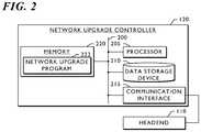
- FIG. 2is a block diagram that illustrates, in detail, one embodiment of the hardware components shown in FIG. 1 . Specifically, FIG. 2 illustrates, in detail, one embodiment of the network upgrade controller 120 .
- the network upgrade controller 120 shown in FIG. 2is a general-purpose computer.
- a bus 200is a communication medium connecting a processor 205 , data storage device 210 (such as a serial ATA (SATA) hard disk drive, optical drive, small computer system interface (SCSI) disk, flash memory, or the like), communication interface 215 , and memory 220 (such as random access memory (RAM), dynamic RAM (DRAM), non-volatile computer memory, flash memory, or the like).
- the communication interface 215allows for two-way communication of data and content between the network upgrade controller 120 and headend 110 , and between the network upgrade controller 120 and CPE 152 via the headend 110 .
- the processor 205 of the network upgrade controller 120performs the disclosed methods by executing sequences of operational instructions that comprise each computer program resident in, or operative on, the memory 220 .
- the memory 220may include operating system, administrative, and database programs that support the programs disclosed in this application.
- the configuration of the memory 220 of the network upgrade controller 120includes a network upgrade program 222 .
- the network upgrade program 222performs the method disclosed in the exemplary embodiments depicted in FIG. 3 and FIG. 4 .
- the processor 205When the processor 205 performs the disclosed method, it stores intermediate results in the memory 220 or data storage device 210 .
- the processor 205may swap these programs, or portions thereof, in and out of the memory 220 as needed, and thus may include fewer than all of these programs at any one time.
- FIG. 3is a network diagram that illustrates one exemplary embodiment of a method for determining upstream transmission capability in an HFC cable plant.
- the exemplary network diagram shown in FIG. 3depicts an area 300 , a portion of the HFC cable plant network 100 , that includes a headend 110 , hub 130 and node 140 components, and CPE 152 devices.
- Each CPE 152 device shown in FIG. 3subtends from either a hub 130 or node 140 component.
- Hub N 130subtends from the headend 110 .
- Node N 1 140 , Node N 2 140 , and Node N 3 140subtend from Hub N 130 .
- CPE N 11 152 , CPE N 12 152 , and CPE N 13 152subtend from Node N 1 140 .
- Node N 2 A 140 and Node N 2 B 140subtend from Node N 2 140 .
- CPE N 2 A 1 152 , CPE N 2 A 2 152 , and CPE N 2 A 3 152subtend from Node N 2 A 140 .
- CPE N 2 B 1 152 , CPE N 2 B 2 152 , CPE N 2 B 3 152 , and CPE N 2 B 4 152subtend from Node N 2 B 140 .
- CPE N 31 152 and CPE N 32 152subtend from Node N 3 140 .
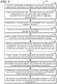
- FIG. 4is a flow diagram that illustrates one embodiment of a method for determining upstream transmission capability in an HFC cable plant.
- the process 400starts by identifying network components in an area of the HFC cable plant network 100 to check for upstream upgrade (step 405 ).
- the cable operatorupgrades each network component, including active and passive network components, in the area that includes a diplexer to utilize the expanded upstream frequencies.
- the area to check for upstream upgradeis the entire HFC cable plant network 100 .
- the areais a subnet, or a portion, of the entire HFC cable plant network 100 .
- the process 400 shown in FIG. 4continues by identifying the CPE 152 devices that subtend from the network components in the area and are capable of transmitting upstream in the newly available frequencies (step 410 ). If the upstream upgrade process misses even one network component in the area, the CPE 152 devices that subtend from any upgraded network component that the upstream upgrade process missed may not work properly in the expanded upstream frequencies. In one embodiment, the CPE 152 devices that the process 400 identifies have the capability of receiving downstream transmissions from the headend 110 in the frequency band to be upgraded, but not all devices have the capability of transmitting in the frequency band to be upgraded.
- the process 400 shown in FIG. 4continues by configuring a downstream transmission that includes a marker channel (step 415 ).
- the marker channelis an existing quadrature amplitude modulation (QAM) channel.
- the marker channelis a continuous tone sent at a frequency within the band of frequencies that the cable operator is converting from downstream to upstream transmissions.
- the configuring of the downstream transmissionincludes configuring a receiver on CMTS 112 that can receive signals within the upgrade frequency band.
- the process 400 shown in FIG. 4continues by initiating the downstream transmission that includes the marker channel to each CPE 152 device in the area (step 420 ).
- the configuring of the downstream transmissionincludes configuring a receiver on the CMTS 112
- the CMTS 112performs the sending of the downstream transmission.
- the process 400 shown in FIG. 4continues by sending a query to each CPE 152 device in the area requesting the status of the downstream marker channel (step 425 ).
- the process 400selects a representative selection of CPE 152 devices in the area such that each area under consideration has at least one CPE 152 device queried with the same results as if all devices were queried.
- the process 400then receives a response from each CPE 152 device in the area to determine the extent of the upstream transmission upgrade in the area by classifying each CPE 152 device as either an upgraded CPE device or an unaffected CPE device (step 430 ).
- the process 400can still proceed.
- a CPE 152 device in the areareceives the query requesting the status of the downstream marker channel (step 425 ) and sends a response that includes a tune success
- the process 400classifies the CPE 152 device as an unaffected CPE device (step 430 ) because the marker channel is still present at the CPE device 152 .
- the process 400classifies the CPE 152 device as an upgraded CPE device (step 430 ) because the marker channel is not present at the CPE device 152 .
- the CPE 152 devices that subtend from those network componentswill not detect the marker channel in the downstream transmission because those network components will prevent the downstream transmission from succeeding.
- the process 400 shown in FIG. 4continues by sending a query to each CPE 152 device in the area classified as an upgraded CPE device to verify the status of the upstream transmission upgrade (step 435 ).
- the query to each CPE 152 device in the area classified as an upgraded CPE deviceis a request to respond upstream on one or more of the frequencies within the upgraded frequency band.
- the configuring of the downstream transmissionincludes configuring a receiver on the CMTS 112 , the CMTS 112 performs the sending of the request to respond upstream on one or more of the frequencies within the upgraded frequency band.
- the process 400determines the upstream transmission capability of each upgraded CPE device based on a response, or absence of a response, from each upgraded CPE device (step 440 ).
- the process 400receives a response from the upgraded CPE device, the upgrade of the upstream transmission path is correct.
- the process 400does not receive a response from the upgraded CPE device, the upgrade of the upstream transmission path is not correct.
- the verificationincludes generating a report of each upgraded CPE device and whether that device responded on the selected frequency or frequencies within the upgraded frequency band.
- the process 400 shown in FIG. 4continues by determining a status of each network component based on the classification of each CPE 152 device subtending from the network component (step 445 ). In one embodiment, the process 400 determines the status of each network component after verification of the upstream transmission upgrade of the CPE 152 devices that subtend from those network components.
- the process 400 shown in FIG. 4continues by determining the upstream transmission capability in the area based on the determined status of each network component (step 450 ).
- the process 400generates a report of the network components and the status of the upstream transmission upgrade for each network component.
- the process 400generates a network topology that illustrates each network component and CPE 152 device in the area, and an indication that each network component or CPE 152 device has been successfully confirmed to have been upgraded.
- the network topologymarks each network branch with incomplete network upgrades based upon the network topology map and responses from the CPE 152 devices.
- the report, or list, of network components, or the network topologyare tools that allow the administrator of the area, or HFC cable plant network 100 , to determine the progress of the upstream transmission upgrade in the HFC cable plant network 100 .
- an exemplary network topologymay indicate that CPE N 31 and CPE N 32 are unaffected CPE devices because the query requesting the status of the downstream marker channel (step 425 ) elicited a tune success response from CPE N 31 and CPE N 32 (step 430 ).
- the administrator of the area 300would determine that the upstream upgrade is not complete for the area 300 , and would know that Node N 3 140 is likely a component that was not upgraded.
- the network topologymay also indicate that CPE N 2 A 1 and CPE N 2 B 2 are upgraded CPE devices because the query requesting the status of the downstream marker channel (step 425 ) elicited a tune failure response from CPE N 2 A 1 and CPE N 2 B 2 (step 430 ). If the network topology indicates, however, that the query verifying the status of the upstream transmission upgrade (step 435 ) elicited a tune success response from CPE N 2 B 2 (step 440 ) and a tune failure response from CPE N 2 A 1 , then the network topology would indicate that Node N 2 and Node N 2 B were both upgraded, but that the upgrade of Node N 2 is complete and the upgrade of Node N 2 A is not yet complete.
- the area 300 depicted in FIG. 3is a simplified network topology.
- a typical HFC cable plant network 100may include many thousands of network components that the administrator needs to examine to determine upstream transmission capability in an HFC cable plant, and to certify that the upstream upgrade is complete.
Landscapes
- Engineering & Computer Science (AREA)
- Signal Processing (AREA)
- Multimedia (AREA)
- Computer Networks & Wireless Communication (AREA)
- Two-Way Televisions, Distribution Of Moving Picture Or The Like (AREA)
- Data Exchanges In Wide-Area Networks (AREA)
Abstract
Description
Claims (19)
Priority Applications (5)
| Application Number | Priority Date | Filing Date | Title |
|---|---|---|---|
| US14/563,680US10581685B2 (en) | 2014-12-08 | 2014-12-08 | Method for automatic tracking of hybrid fiber coaxial upstream service upgrades |
| PT151937646TPT3032824T (en) | 2014-12-08 | 2015-11-09 | Method for automatic tracking of hybrid fiber coaxial upstream service upgrades |
| GB1519775.9AGB2533211B (en) | 2014-12-08 | 2015-11-09 | Method for automatic tracking of hybrid fiber coaxial upstream service upgrades |
| EP15193764.6AEP3032824B1 (en) | 2014-12-08 | 2015-11-09 | Method for automatic tracking of hybrid fiber coaxial upstream service upgrades |
| ES15193764TES2820750T3 (en) | 2014-12-08 | 2015-11-09 | Method for automatic tracking of coax and fiber hybrid upstream service updates |
Applications Claiming Priority (1)
| Application Number | Priority Date | Filing Date | Title |
|---|---|---|---|
| US14/563,680US10581685B2 (en) | 2014-12-08 | 2014-12-08 | Method for automatic tracking of hybrid fiber coaxial upstream service upgrades |
Publications (2)
| Publication Number | Publication Date |
|---|---|
| US20160164758A1 US20160164758A1 (en) | 2016-06-09 |
| US10581685B2true US10581685B2 (en) | 2020-03-03 |
Family
ID=54782408
Family Applications (1)
| Application Number | Title | Priority Date | Filing Date |
|---|---|---|---|
| US14/563,680ActiveUS10581685B2 (en) | 2014-12-08 | 2014-12-08 | Method for automatic tracking of hybrid fiber coaxial upstream service upgrades |
Country Status (5)
| Country | Link |
|---|---|
| US (1) | US10581685B2 (en) |
| EP (1) | EP3032824B1 (en) |
| ES (1) | ES2820750T3 (en) |
| GB (1) | GB2533211B (en) |
| PT (1) | PT3032824T (en) |
Families Citing this family (1)
| Publication number | Priority date | Publication date | Assignee | Title |
|---|---|---|---|---|
| CA3175654A1 (en)* | 2021-09-17 | 2023-03-17 | Comcast Cable Communications, Llc | Network management for band splits |
Citations (13)
| Publication number | Priority date | Publication date | Assignee | Title |
|---|---|---|---|---|
| US20020056134A1 (en)* | 2000-06-30 | 2002-05-09 | Shuji Abe | Transmission/reception integrated radio-frequency apparatus |
| US20020144290A1 (en)* | 2001-03-27 | 2002-10-03 | Shlomo Ovadia | System and related methods facilitating the rapid detection and acquisition of a data channel in a cable modem |
| US20030016701A1 (en)* | 2001-07-23 | 2003-01-23 | Hinson Scott R. | Distributed block frequency converter |
| WO2005048510A2 (en) | 2003-11-05 | 2005-05-26 | Arris International, Inc. | Method and system for providing video and data traffic packets from the same device |
| US20060235476A1 (en)* | 2005-04-18 | 2006-10-19 | Gunderson Bruce D | Method and apparatus for identifying oversensing using far-field intracardiac electrograms and marker channels |
| US20090074423A1 (en)* | 2007-09-17 | 2009-03-19 | Tellabs Vienna, Inc. | Method and apparatus for configuring an optical network terminal |
| US20110145809A1 (en)* | 2009-12-15 | 2011-06-16 | Samsung Electronics Co. Ltd. | Method and apparatus for upgrading software in customer premise equipment |
| US20130125182A1 (en)* | 2011-11-10 | 2013-05-16 | General Instrument Corporation | Tunable rf return path filter with automatic channel plan detection |
| US20130322504A1 (en)* | 2012-06-04 | 2013-12-05 | Cisco Technology, Inc. | System and method for discovering and verifying a hybrid fiber-coaxial topology in a cable network environment |
| US8910230B2 (en)* | 2010-01-22 | 2014-12-09 | Gainspeed, Inc. | Method of transforming HFC CATV analog fiber transmission to digital fiber transmission |
| US8938769B2 (en)* | 2010-01-22 | 2015-01-20 | Gainspeed, Inc. | Virtual converged cable access platforms for HFC cable networks |
| US9015270B2 (en)* | 2010-10-08 | 2015-04-21 | Time Warner Cable Enterprises Llc | Apparatus and methods for enforcing content protection rules during data transfer between devices |
| US9692612B2 (en)* | 2010-01-22 | 2017-06-27 | Alcatel-Lucent Usa Inc. | Distributed CCAP cable modem termination system |
Family Cites Families (3)
| Publication number | Priority date | Publication date | Assignee | Title |
|---|---|---|---|---|
| US2013332A (en)* | 1931-03-21 | 1935-09-03 | Patent & Licensing Corp | Building material and method of and apparatus for making same |
| US11076189B2 (en)* | 2009-03-30 | 2021-07-27 | Time Warner Cable Enterprises Llc | Personal media channel apparatus and methods |
| CN104348720B (en)* | 2013-07-25 | 2018-05-04 | 中兴通讯股份有限公司 | A kind of multi-domain path calculates the processing method and path-calculating element of failure |
- 2014
- 2014-12-08USUS14/563,680patent/US10581685B2/enactiveActive
- 2015
- 2015-11-09PTPT151937646Tpatent/PT3032824T/enunknown
- 2015-11-09EPEP15193764.6Apatent/EP3032824B1/enactiveActive
- 2015-11-09GBGB1519775.9Apatent/GB2533211B/ennot_activeExpired - Fee Related
- 2015-11-09ESES15193764Tpatent/ES2820750T3/enactiveActive
Patent Citations (13)
| Publication number | Priority date | Publication date | Assignee | Title |
|---|---|---|---|---|
| US20020056134A1 (en)* | 2000-06-30 | 2002-05-09 | Shuji Abe | Transmission/reception integrated radio-frequency apparatus |
| US20020144290A1 (en)* | 2001-03-27 | 2002-10-03 | Shlomo Ovadia | System and related methods facilitating the rapid detection and acquisition of a data channel in a cable modem |
| US20030016701A1 (en)* | 2001-07-23 | 2003-01-23 | Hinson Scott R. | Distributed block frequency converter |
| WO2005048510A2 (en) | 2003-11-05 | 2005-05-26 | Arris International, Inc. | Method and system for providing video and data traffic packets from the same device |
| US20060235476A1 (en)* | 2005-04-18 | 2006-10-19 | Gunderson Bruce D | Method and apparatus for identifying oversensing using far-field intracardiac electrograms and marker channels |
| US20090074423A1 (en)* | 2007-09-17 | 2009-03-19 | Tellabs Vienna, Inc. | Method and apparatus for configuring an optical network terminal |
| US20110145809A1 (en)* | 2009-12-15 | 2011-06-16 | Samsung Electronics Co. Ltd. | Method and apparatus for upgrading software in customer premise equipment |
| US8910230B2 (en)* | 2010-01-22 | 2014-12-09 | Gainspeed, Inc. | Method of transforming HFC CATV analog fiber transmission to digital fiber transmission |
| US8938769B2 (en)* | 2010-01-22 | 2015-01-20 | Gainspeed, Inc. | Virtual converged cable access platforms for HFC cable networks |
| US9692612B2 (en)* | 2010-01-22 | 2017-06-27 | Alcatel-Lucent Usa Inc. | Distributed CCAP cable modem termination system |
| US9015270B2 (en)* | 2010-10-08 | 2015-04-21 | Time Warner Cable Enterprises Llc | Apparatus and methods for enforcing content protection rules during data transfer between devices |
| US20130125182A1 (en)* | 2011-11-10 | 2013-05-16 | General Instrument Corporation | Tunable rf return path filter with automatic channel plan detection |
| US20130322504A1 (en)* | 2012-06-04 | 2013-12-05 | Cisco Technology, Inc. | System and method for discovering and verifying a hybrid fiber-coaxial topology in a cable network environment |
Non-Patent Citations (8)
| Title |
|---|
| "Data Over Cable Service Interface Specifications: DOCSIS 3.0, Physical Layer Specification", Document No. CM-SP-PHYv3.0-I04-070518, Cable Television Laboratories, Inc., May 2007. |
| "Data-Over-Cable Service Interface Specifications: DOCSIS 3.1, Physical Layer Specification", Document No. CM-SP-PHYv3.1-I01-131029, Cable Television Laboratories, Inc., Oct. 2013. |
| D. Urban, "Comparison of Techniques for HFC Upstream Capacity Increase", National Cable & Telecommunications Association (NCTA), 2010 Spring Technical Forum Proceedings (2010). |
| Examination Report, RE: European Application No. 15193764.6, dated Nov. 20, 2018. |
| Great Britain Combined Search and Examination Report, RE: Application No. GB1519775.9, dated Jan. 5, 2016. |
| J. Chapman, "Taking the DOCSIS Upstream to a Gigabit Per Second", National Cable & Telecommunications Association (NCTA), 2010 Spring Technical Forum Proceedings (2010). |
| P. Miguelez, "Making Room for DOCSIS 3.1 and EPoC-Is your cable plant ready for an OFDM world?", National Cable & Telecommunications Association (NCTA), 2013 Spring Technical Forum Proceedings (2013). |
| P. Miguelez, "Making Room for DOCSIS 3.1 and EPoC—Is your cable plant ready for an OFDM world?", National Cable & Telecommunications Association (NCTA), 2013 Spring Technical Forum Proceedings (2013). |
Also Published As
| Publication number | Publication date |
|---|---|
| EP3032824B1 (en) | 2020-08-05 |
| EP3032824A3 (en) | 2016-07-13 |
| GB201519775D0 (en) | 2015-12-23 |
| PT3032824T (en) | 2020-10-01 |
| US20160164758A1 (en) | 2016-06-09 |
| ES2820750T3 (en) | 2021-04-22 |
| EP3032824A2 (en) | 2016-06-15 |
| GB2533211A (en) | 2016-06-15 |
| GB2533211B (en) | 2018-06-27 |
Similar Documents
| Publication | Publication Date | Title |
|---|---|---|
| US9419862B2 (en) | System and method for discovering and verifying a hybrid fiber-coaxial topology in a cable network environment | |
| US8649421B2 (en) | Cable modem for network measurements | |
| US10021000B2 (en) | Provisioning in support of an embedded cable modem MAC address | |
| US9699507B2 (en) | Addressing and locating in-line coaxial cable devices within customer premises in cable-based networks | |
| US10498783B2 (en) | Non-DSG mechanisms for aligning client devices with their multicast data flows in a DOCSIS network environment | |
| US20250184254A1 (en) | Network management for band splits | |
| US11363063B2 (en) | Botnet detection and mitigation | |
| US11588842B2 (en) | Network anomaly detection and mitigation simulation tool | |
| US10945036B2 (en) | Set top box security tracking | |
| US11611787B1 (en) | Systems and methods for signaling host devices via a broadcast channel with grouping filters | |
| US10581685B2 (en) | Method for automatic tracking of hybrid fiber coaxial upstream service upgrades | |
| US12261762B2 (en) | Detecting and localizing cable plant impairments using full band capture spectrum analysis | |
| CN107683584B (en) | HFC network topology discovery method, network equipment and network system | |
| US20230268956A1 (en) | Docsis radio frequency (rf) leakage management | |
| US11398967B1 (en) | Leakage detection on hybrid fiber-coaxial (HFC) access networks | |
| US9813763B2 (en) | Application for in-field discovery, diagnosis and repair of a set-top device | |
| US9900406B1 (en) | Method and apparatus for demand-based cable upstream channel assignment | |
| US20230362152A1 (en) | Mobile dynamic application packet kit (apk) | |
| KR100960141B1 (en) | Cable modem and distribution center that provides Internet service and broadcasting service and its service providing method | |
| US12114025B2 (en) | Video client management of video service feature flags | |
| US9525582B1 (en) | Selectively ordering application of provisioning from multiple sources for network equipment | |
| US12238464B2 (en) | Remote configuration and monitoring of smart amplifiers in cable systems | |
| US8806553B1 (en) | Prioritized channel scanning | |
| CN106330969B (en) | A kind of packet identification method during CM is online in CMC system | |
| TW202301835A (en) | System and method for identifying network equipment from a remote location |
Legal Events
| Date | Code | Title | Description |
|---|---|---|---|
| AS | Assignment | Owner name:ARRIS ENTERPRISES, INC., GEORGIA Free format text:ASSIGNMENT OF ASSIGNORS INTEREST;ASSIGNOR:ANSLEY, CAROL J.;REEL/FRAME:034539/0989 Effective date:20141208 | |
| AS | Assignment | Owner name:BANK OF AMERICA, N.A., AS ADMINISTRATIVE AGENT, NORTH CAROLINA Free format text:SECURITY INTEREST;ASSIGNORS:ARRIS GROUP, INC.;ARRIS ENTERPRISES, INC.;ARRIS INTERNATIONAL LIMITED;AND OTHERS;REEL/FRAME:036020/0789 Effective date:20150618 Owner name:BANK OF AMERICA, N.A., AS ADMINISTRATIVE AGENT, NO Free format text:SECURITY INTEREST;ASSIGNORS:ARRIS GROUP, INC.;ARRIS ENTERPRISES, INC.;ARRIS INTERNATIONAL LIMITED;AND OTHERS;REEL/FRAME:036020/0789 Effective date:20150618 | |
| AS | Assignment | Owner name:ARRIS ENTERPRISES LLC, PENNSYLVANIA Free format text:CHANGE OF NAME;ASSIGNOR:ARRIS ENTERPRISES INC;REEL/FRAME:041995/0031 Effective date:20151231 | |
| STPP | Information on status: patent application and granting procedure in general | Free format text:NON FINAL ACTION MAILED | |
| AS | Assignment | Owner name:TEXSCAN CORPORATION, PENNSYLVANIA Free format text:TERMINATION AND RELEASE OF SECURITY INTEREST IN PATENTS;ASSIGNOR:BANK OF AMERICA, N.A., AS ADMINISTRATIVE AGENT;REEL/FRAME:050721/0401 Effective date:20190404 Owner name:POWER GUARD, INC., PENNSYLVANIA Free format text:TERMINATION AND RELEASE OF SECURITY INTEREST IN PATENTS;ASSIGNOR:BANK OF AMERICA, N.A., AS ADMINISTRATIVE AGENT;REEL/FRAME:050721/0401 Effective date:20190404 Owner name:NEXTLEVEL SYSTEMS (PUERTO RICO), INC., PENNSYLVANI Free format text:TERMINATION AND RELEASE OF SECURITY INTEREST IN PATENTS;ASSIGNOR:BANK OF AMERICA, N.A., AS ADMINISTRATIVE AGENT;REEL/FRAME:050721/0401 Effective date:20190404 Owner name:ARRIS GLOBAL SERVICES, INC., PENNSYLVANIA Free format text:TERMINATION AND RELEASE OF SECURITY INTEREST IN PATENTS;ASSIGNOR:BANK OF AMERICA, N.A., AS ADMINISTRATIVE AGENT;REEL/FRAME:050721/0401 Effective date:20190404 Owner name:ARRIS INTERNATIONAL LIMITED, PENNSYLVANIA Free format text:TERMINATION AND RELEASE OF SECURITY INTEREST IN PATENTS;ASSIGNOR:BANK OF AMERICA, N.A., AS ADMINISTRATIVE AGENT;REEL/FRAME:050721/0401 Effective date:20190404 Owner name:ARCHIE U.S. HOLDINGS LLC, PENNSYLVANIA Free format text:TERMINATION AND RELEASE OF SECURITY INTEREST IN PATENTS;ASSIGNOR:BANK OF AMERICA, N.A., AS ADMINISTRATIVE AGENT;REEL/FRAME:050721/0401 Effective date:20190404 Owner name:GIC INTERNATIONAL HOLDCO LLC, PENNSYLVANIA Free format text:TERMINATION AND RELEASE OF SECURITY INTEREST IN PATENTS;ASSIGNOR:BANK OF AMERICA, N.A., AS ADMINISTRATIVE AGENT;REEL/FRAME:050721/0401 Effective date:20190404 Owner name:ARRIS ENTERPRISES, INC., PENNSYLVANIA Free format text:TERMINATION AND RELEASE OF SECURITY INTEREST IN PATENTS;ASSIGNOR:BANK OF AMERICA, N.A., AS ADMINISTRATIVE AGENT;REEL/FRAME:050721/0401 Effective date:20190404 Owner name:JERROLD DC RADIO, INC., PENNSYLVANIA Free format text:TERMINATION AND RELEASE OF SECURITY INTEREST IN PATENTS;ASSIGNOR:BANK OF AMERICA, N.A., AS ADMINISTRATIVE AGENT;REEL/FRAME:050721/0401 Effective date:20190404 Owner name:GIC INTERNATIONAL CAPITAL LLC, PENNSYLVANIA Free format text:TERMINATION AND RELEASE OF SECURITY INTEREST IN PATENTS;ASSIGNOR:BANK OF AMERICA, N.A., AS ADMINISTRATIVE AGENT;REEL/FRAME:050721/0401 Effective date:20190404 Owner name:BIG BAND NETWORKS, INC., PENNSYLVANIA Free format text:TERMINATION AND RELEASE OF SECURITY INTEREST IN PATENTS;ASSIGNOR:BANK OF AMERICA, N.A., AS ADMINISTRATIVE AGENT;REEL/FRAME:050721/0401 Effective date:20190404 Owner name:ARRIS SOLUTIONS, INC., PENNSYLVANIA Free format text:TERMINATION AND RELEASE OF SECURITY INTEREST IN PATENTS;ASSIGNOR:BANK OF AMERICA, N.A., AS ADMINISTRATIVE AGENT;REEL/FRAME:050721/0401 Effective date:20190404 Owner name:ARRIS HOLDINGS CORP. OF ILLINOIS, INC., PENNSYLVAN Free format text:TERMINATION AND RELEASE OF SECURITY INTEREST IN PATENTS;ASSIGNOR:BANK OF AMERICA, N.A., AS ADMINISTRATIVE AGENT;REEL/FRAME:050721/0401 Effective date:20190404 Owner name:ARRIS GROUP, INC., PENNSYLVANIA Free format text:TERMINATION AND RELEASE OF SECURITY INTEREST IN PATENTS;ASSIGNOR:BANK OF AMERICA, N.A., AS ADMINISTRATIVE AGENT;REEL/FRAME:050721/0401 Effective date:20190404 Owner name:ARCHIE U.S. MERGER LLC, PENNSYLVANIA Free format text:TERMINATION AND RELEASE OF SECURITY INTEREST IN PATENTS;ASSIGNOR:BANK OF AMERICA, N.A., AS ADMINISTRATIVE AGENT;REEL/FRAME:050721/0401 Effective date:20190404 Owner name:ARRIS TECHNOLOGY, INC., PENNSYLVANIA Free format text:TERMINATION AND RELEASE OF SECURITY INTEREST IN PATENTS;ASSIGNOR:BANK OF AMERICA, N.A., AS ADMINISTRATIVE AGENT;REEL/FRAME:050721/0401 Effective date:20190404 Owner name:NEXTLEVEL SYSTEMS (PUERTO RICO), INC., PENNSYLVANIA Free format text:TERMINATION AND RELEASE OF SECURITY INTEREST IN PATENTS;ASSIGNOR:BANK OF AMERICA, N.A., AS ADMINISTRATIVE AGENT;REEL/FRAME:050721/0401 Effective date:20190404 Owner name:ARRIS HOLDINGS CORP. OF ILLINOIS, INC., PENNSYLVANIA Free format text:TERMINATION AND RELEASE OF SECURITY INTEREST IN PATENTS;ASSIGNOR:BANK OF AMERICA, N.A., AS ADMINISTRATIVE AGENT;REEL/FRAME:050721/0401 Effective date:20190404 | |
| AS | Assignment | Owner name:ARRIS ENTERPRISES LLC, GEORGIA Free format text:CHANGE OF NAME;ASSIGNOR:ARRIS ENTERPRISES, INC.;REEL/FRAME:049586/0470 Effective date:20151231 | |
| AS | Assignment | Owner name:WILMINGTON TRUST, NATIONAL ASSOCIATION, AS COLLATE Free format text:PATENT SECURITY AGREEMENT;ASSIGNOR:ARRIS ENTERPRISES LLC;REEL/FRAME:049820/0495 Effective date:20190404 Owner name:JPMORGAN CHASE BANK, N.A., NEW YORK Free format text:ABL SECURITY AGREEMENT;ASSIGNORS:COMMSCOPE, INC. OF NORTH CAROLINA;COMMSCOPE TECHNOLOGIES LLC;ARRIS ENTERPRISES LLC;AND OTHERS;REEL/FRAME:049892/0396 Effective date:20190404 Owner name:JPMORGAN CHASE BANK, N.A., NEW YORK Free format text:TERM LOAN SECURITY AGREEMENT;ASSIGNORS:COMMSCOPE, INC. OF NORTH CAROLINA;COMMSCOPE TECHNOLOGIES LLC;ARRIS ENTERPRISES LLC;AND OTHERS;REEL/FRAME:049905/0504 Effective date:20190404 Owner name:WILMINGTON TRUST, NATIONAL ASSOCIATION, AS COLLATERAL AGENT, CONNECTICUT Free format text:PATENT SECURITY AGREEMENT;ASSIGNOR:ARRIS ENTERPRISES LLC;REEL/FRAME:049820/0495 Effective date:20190404 | |
| STPP | Information on status: patent application and granting procedure in general | Free format text:RESPONSE TO NON-FINAL OFFICE ACTION ENTERED AND FORWARDED TO EXAMINER | |
| STPP | Information on status: patent application and granting procedure in general | Free format text:NOTICE OF ALLOWANCE MAILED -- APPLICATION RECEIVED IN OFFICE OF PUBLICATIONS | |
| STPP | Information on status: patent application and granting procedure in general | Free format text:PUBLICATIONS -- ISSUE FEE PAYMENT VERIFIED | |
| STCF | Information on status: patent grant | Free format text:PATENTED CASE | |
| AS | Assignment | Owner name:WILMINGTON TRUST, DELAWARE Free format text:SECURITY INTEREST;ASSIGNORS:ARRIS SOLUTIONS, INC.;ARRIS ENTERPRISES LLC;COMMSCOPE TECHNOLOGIES LLC;AND OTHERS;REEL/FRAME:060752/0001 Effective date:20211115 | |
| MAFP | Maintenance fee payment | Free format text:PAYMENT OF MAINTENANCE FEE, 4TH YEAR, LARGE ENTITY (ORIGINAL EVENT CODE: M1551); ENTITY STATUS OF PATENT OWNER: LARGE ENTITY Year of fee payment:4 | |
| AS | Assignment | Owner name:APOLLO ADMINISTRATIVE AGENCY LLC, NEW YORK Free format text:SECURITY INTEREST;ASSIGNORS:ARRIS ENTERPRISES LLC;COMMSCOPE TECHNOLOGIES LLC;COMMSCOPE INC., OF NORTH CAROLINA;AND OTHERS;REEL/FRAME:069889/0114 Effective date:20241217 | |
| AS | Assignment | Owner name:RUCKUS WIRELESS, LLC (F/K/A RUCKUS WIRELESS, INC.), NORTH CAROLINA Free format text:RELEASE OF SECURITY INTEREST AT REEL/FRAME 049905/0504;ASSIGNOR:JPMORGAN CHASE BANK, N.A., AS COLLATERAL AGENT;REEL/FRAME:071477/0255 Effective date:20241217 Owner name:COMMSCOPE TECHNOLOGIES LLC, NORTH CAROLINA Free format text:RELEASE OF SECURITY INTEREST AT REEL/FRAME 049905/0504;ASSIGNOR:JPMORGAN CHASE BANK, N.A., AS COLLATERAL AGENT;REEL/FRAME:071477/0255 Effective date:20241217 Owner name:COMMSCOPE, INC. OF NORTH CAROLINA, NORTH CAROLINA Free format text:RELEASE OF SECURITY INTEREST AT REEL/FRAME 049905/0504;ASSIGNOR:JPMORGAN CHASE BANK, N.A., AS COLLATERAL AGENT;REEL/FRAME:071477/0255 Effective date:20241217 Owner name:ARRIS SOLUTIONS, INC., NORTH CAROLINA Free format text:RELEASE OF SECURITY INTEREST AT REEL/FRAME 049905/0504;ASSIGNOR:JPMORGAN CHASE BANK, N.A., AS COLLATERAL AGENT;REEL/FRAME:071477/0255 Effective date:20241217 Owner name:ARRIS TECHNOLOGY, INC., NORTH CAROLINA Free format text:RELEASE OF SECURITY INTEREST AT REEL/FRAME 049905/0504;ASSIGNOR:JPMORGAN CHASE BANK, N.A., AS COLLATERAL AGENT;REEL/FRAME:071477/0255 Effective date:20241217 Owner name:ARRIS ENTERPRISES LLC (F/K/A ARRIS ENTERPRISES, INC.), NORTH CAROLINA Free format text:RELEASE OF SECURITY INTEREST AT REEL/FRAME 049905/0504;ASSIGNOR:JPMORGAN CHASE BANK, N.A., AS COLLATERAL AGENT;REEL/FRAME:071477/0255 Effective date:20241217 |