US10581650B2 - Enhancing isolation in radio frequency multiplexers - Google Patents
Enhancing isolation in radio frequency multiplexersDownload PDFInfo
- Publication number
- US10581650B2 US10581650B2US15/220,181US201615220181AUS10581650B2US 10581650 B2US10581650 B2US 10581650B2US 201615220181 AUS201615220181 AUS 201615220181AUS 10581650 B2US10581650 B2US 10581650B2
- Authority
- US
- United States
- Prior art keywords
- radio frequency
- ports
- multiplexer
- filters
- isolation
- Prior art date
- Legal status (The legal status is an assumption and is not a legal conclusion. Google has not performed a legal analysis and makes no representation as to the accuracy of the status listed.)
- Active
Links
- 238000002955isolationMethods0.000titleclaimsabstractdescription96
- 230000002708enhancing effectEffects0.000titledescription6
- 238000004891communicationMethods0.000claimsdescription47
- 230000004044responseEffects0.000claimsdescription17
- 230000002776aggregationEffects0.000claimsdescription3
- 238000004220aggregationMethods0.000claimsdescription3
- 230000006870functionEffects0.000description38
- 238000012546transferMethods0.000description29
- 238000010897surface acoustic wave methodMethods0.000description14
- 230000008878couplingEffects0.000description11
- 238000010168coupling processMethods0.000description11
- 238000005859coupling reactionMethods0.000description11
- 238000005516engineering processMethods0.000description10
- 230000008901benefitEffects0.000description8
- 238000000034methodMethods0.000description8
- 238000003780insertionMethods0.000description7
- 230000037431insertionEffects0.000description7
- 239000000463materialSubstances0.000description5
- 238000004590computer programMethods0.000description4
- 230000001413cellular effectEffects0.000description3
- 230000008859changeEffects0.000description3
- 230000001934delayEffects0.000description3
- 238000001914filtrationMethods0.000description3
- 239000000919ceramicSubstances0.000description2
- 238000013461designMethods0.000description2
- 238000004088simulationMethods0.000description2
- 230000009471actionEffects0.000description1
- 238000013459approachMethods0.000description1
- 230000005540biological transmissionEffects0.000description1
- 239000003990capacitorSubstances0.000description1
- 238000006243chemical reactionMethods0.000description1
- 238000007796conventional methodMethods0.000description1
- 230000001419dependent effectEffects0.000description1
- 230000005670electromagnetic radiationEffects0.000description1
- 238000010348incorporationMethods0.000description1
- 230000010365information processingEffects0.000description1
- 230000010354integrationEffects0.000description1
- 238000005259measurementMethods0.000description1
- 230000007246mechanismEffects0.000description1
- 238000012986modificationMethods0.000description1
- 230000004048modificationEffects0.000description1
- 230000009467reductionEffects0.000description1
- 238000012827research and developmentMethods0.000description1
- 230000035945sensitivityEffects0.000description1
- 239000010409thin filmSubstances0.000description1
Images


Classifications
- H—ELECTRICITY
- H04—ELECTRIC COMMUNICATION TECHNIQUE
- H04L—TRANSMISSION OF DIGITAL INFORMATION, e.g. TELEGRAPHIC COMMUNICATION
- H04L25/00—Baseband systems
- H04L25/02—Details ; arrangements for supplying electrical power along data transmission lines
- H04L25/03—Shaping networks in transmitter or receiver, e.g. adaptive shaping networks
- H04L25/03891—Spatial equalizers
- H04L25/03949—Spatial equalizers equalizer selection or adaptation based on feedback
- H—ELECTRICITY
- H04—ELECTRIC COMMUNICATION TECHNIQUE
- H04B—TRANSMISSION
- H04B1/00—Details of transmission systems, not covered by a single one of groups H04B3/00 - H04B13/00; Details of transmission systems not characterised by the medium used for transmission
- H04B1/005—Details of transmission systems, not covered by a single one of groups H04B3/00 - H04B13/00; Details of transmission systems not characterised by the medium used for transmission adapting radio receivers, transmitters andtransceivers for operation on two or more bands, i.e. frequency ranges
- H04B1/0053—Details of transmission systems, not covered by a single one of groups H04B3/00 - H04B13/00; Details of transmission systems not characterised by the medium used for transmission adapting radio receivers, transmitters andtransceivers for operation on two or more bands, i.e. frequency ranges with common antenna for more than one band
- H04B1/0057—Details of transmission systems, not covered by a single one of groups H04B3/00 - H04B13/00; Details of transmission systems not characterised by the medium used for transmission adapting radio receivers, transmitters andtransceivers for operation on two or more bands, i.e. frequency ranges with common antenna for more than one band using diplexing or multiplexing filters for selecting the desired band
Definitions
- Certain embodiments of the disclosurerelate to radio frequency (RF) multiplexers that may be used in multi-band communication receivers, transmitters, or transceivers, for example. More specifically, certain embodiments of the disclosure relate to a method and system for enhancing isolation in RF multiplexers.
- RFradio frequency
- RF multiplexersare multi-port networks and are components of communication systems that support multiple frequency bands or simultaneous transmit and receive functions in a Frequency Division Duplex (FDD) scheme.
- FDDFrequency Division Duplex
- High selectivity, low insertion loss, high isolation between ports, compact size, ability to handle large signals (power handling), high linearity, manufacturability, and low costmay be some of the desired features for RF multiplexers.
- the RF duplexera three-port network, is the most common form of RF multiplexer, where the ports are nominally connected to an antenna, a transmitter, and a receiver of an FDD communication system.
- RF switchescan select the appropriate RF filters and duplexers that correspond to the desired RF frequency bands.
- Some wireless communication standardsrequire simultaneous operation of the receiver or transmitter at multiple frequency bands to achieve higher capacity, diversity, or data rate.
- the fourth generation wireless standardscommonly referred to as 4G, envision Carrier Aggregation (CA) to increase the total bandwidth to the user.
- CACarrier Aggregation
- RF multiplexerscan be used.
- An RF multiplexerin its simplest form, is a 1 ⁇ N network that includes 1 nominal input and N nominal output ports, where N is a positive integer.
- Nis a positive integer.
- the transfer functions from the input to each of the N output portsare non-overlapping in frequency while the N output ports are isolated at their respective frequency bands. In other words, the transfer functions from each of the output ports to every other output port should have a small magnitude at the frequency bands corresponding to those two ports.
- Conventional 1 ⁇ N RF multiplexersinclude RF Band-Pass Filters (BPF) with distinct passband frequencies that are connected to a common port using a passive network or a number of passive networks.
- BPFBand-Pass Filters
- the passive network or networkscan ensure proper impedance at all frequency bands of interest and may assist in enhancing the frequency response.
- Linearity, noise, and power handling requirementsmight lead to utilization of passive RF filters and multiplexers in many applications.
- the performance of passive RF filters and multiplexersmay be limited by the quality factor (Q) of the components that are used in their realization.
- Qquality factor
- the filter selectivity as well as passband requirementmay lead to a filter topology and filter order. For a given RF filter or duplexer topology and order, insertion loss may reduce with the increase of component Q.
- capacitors, inductors, or transmission linescan be used to realize passive RF filters and duplexers.
- Electromagnetic resonators, including waveguide resonators and dielectric resonators,can also be used to realize passive filters and duplexers. The quality factor of such components is proportional to their overall physical size. As such, it has been difficult to realize compact low-loss selective passive RF filters and duplexers using electromagnetic components and resonators.
- Piezoelectric materialcan be used to realize compact high-Q resonators.
- Surface acoustic wave (SAW) resonatorshave been widely used to realize compact low-loss selective RF filters and duplexers as well as oscillators.
- Bulk acoustic wave (BAW) resonatorshave been used to construct high-performance RF filters and duplexers as well as oscillators.
- Ceramic resonators and micro electro mechanical system (MEMS) resonators with high quality factorhave also been used in frequency generation as well as filtering applications.
- RF SAW filters and duplexershave been used widely in wireless communications such as cellular phones, wireless local area network (WLAN) transceivers, global positioning system (GPS) receivers, cordless phones, and so forth.
- RF SAW filtershave been used as band-select filters, image-reject filters, intermediate frequency (IF) filters, transmitter noise or spur reduction filters, and so forth.
- a smartphonemay have several SAW resonators, SAW filters, and SAW duplexers to support various communication systems and standards.
- BAW resonatorsthat have lower loss (or higher Q) or are more compact, especially at higher frequencies, compared with SAW resonators. Therefore, RF filters and duplexers that use BAW resonators may have lower insertion loss, or higher selectivity, or smaller form factor compared with those that utilize SAW resonators especially at higher frequencies.
- Thin film bulk acoustic resonators (FBAR) and solidly mounted resonator (SMR)are common examples of BAW resonators.
- Modern wireless communication standardsdesignate many different operational frequency bands to support the increase in the overall wireless capacity and reach.
- current cellular phone standardsmay include RF frequency bands that span around 700 MHz to around 4000 MHz.
- the frequency spacing between adjacent frequency bands or channels within the same application or different applicationsmay be reduced. This may be done, for instance, by reducing the guard bands in wireless standard or by placing the transmit and receive frequency bands in an FDD scheme closer to each other.
- RF filters and duplexers with higher selectivitymay be required. More selective RF filters and duplexers that utilize a given component or technology (SAW, BAW, etc.) may incur more in-band insertion loss.
- the higher RF filter or duplexer insertion lossmay reduce the wireless receiver noise figure and sensitivity, increase the wireless transmitter power consumption or reduce the transmitted power, and/or deteriorate the overall performance of a communication system.
- the choice of technologymay depend on the technical performance, such as power consumption as well as economic and business considerations such as cost, size, and time to market. For instance, while one technology may offer a better performance compared with another technology, it may not be adopted for a commercial system that is cost sensitive. In the case of RF filters and duplexers, it may be desirable to use a technology that leads to the lowest-cost and/or most-compact solution, as long as a predetermined performance criterion is met. In other words, a more expensive or larger solution may not be adopted, even if it offers a better performance as compared with an alternative solution that meets an acceptable performance level at a lower cost and/or size.
- RF filters and multiplexers that use BAW resonatorsmay offer lower loss compared with RF filters and multiplexers that use SAW resonators for a given set of specifications, the higher relative cost of BAW technology, as well as its relatively smaller number of suppliers, may disfavor their usage in certain applications and standards.
- Other considerationsmay be the ease of integration with the rest of the components in a communication system. For instance, there may be performance, business, or economic advantages to integrate RF filters and multiplexers with low noise amplifiers (LNA), power amplifiers (PA), transmit/receive (T/R) or band-select switches, impedance matching networks, etc.
- LNAlow noise amplifiers
- PApower amplifiers
- T/Rtransmit/receive
- a modern wireless communication devicesuch as a smartphone, may have a number of SAW filters and multiplexers as well as a number of BAW filter and duplexers.
- Each SAW or BAW filter or duplexermay be used for a specific communication application, standard, or frequency band.
- a conventional method to design acoustic resonator based filters and duplexeris to decide upon the number of resonators to be used depending on the required stopband rejection in the case of filters or the required isolation in the case of duplexers.
- the larger the number of resonators used in filter designthe larger may be the order of the filter and the sharper may be the filter roll-off around passband. Sharper filter roll-off may mean higher stopband rejection.
- the number of resonators used in the TX and RX filters of the duplexermay determine the total isolation from TX to RX.
- the larger the order of the TX and RX filtersi.e., the larger the number of resonators used in them), the larger may be the amount of isolation between TX and RX.
- the insertion loss in the filter and duplexermay be directly proportional to the number of the resonators used.
- the larger the order of the filter and the TX and RX filter, the largermay be the loss of the filter and duplexer, respectively.
- a system and/or method for enhancing isolation in RF multiplexerssubstantially as shown in and/or described in connection with at least one of the figures, as set forth more completely in the claims.
- An objective of this disclosureis to enable realization of RF multiplexers with high isolation between the ports. Another objective of this disclosure is to enhance the isolation of RF multiplexers by adding isolation enhancement networks.
- Represented simulation results of various embodimentsare only for illustrative reasons, and are not meant to cover all possible responses that various embodiments enable.
- some of the presented simulation resultsmight cover filters with a single passband and at least one stopband (or notch) in their transfer functions. Filters with multiple passbands or stopbands may also be realized using the embodiments or other teachings of this disclosure. Filters whose transfer functions fundamentally change as a function of at least one stimulus may also be realized using the embodiments or other teachings of this disclosure.
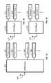
- FIGS. 1A-1Cillustrate various applications of an RF multiplexer in the front-end of a multi-band communication system.
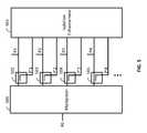
- FIGS. 2A-2Billustrate two realizations of an RF multiplexer that includes individual band-pass filters and impedance matching passive network(s).
- FIGS. 3A-3Iillustrate a representative frequency response of an RF multiplexer.
- FIG. 4illustrates an embodiment of an RF multiplexer with an added isolation enhancement network.
- FIG. 5illustrates an embodiment of an RF multiplexer with an added isolation enhancement network that uses passive coupling networks to sample the signals present at individual ports (sampled ports).
- FIG. 6illustrates an embodiment of an isolation cancellation network that includes passive networks between multiplexer ports and sampled ports.
- FIGS. 7A-7Billustrate two embodiments of an RF multiplexer with an added isolation enhancement network that use either a passive combiner or multiple coupling networks to couple multiple processed signals through passive networks into each sampled port.
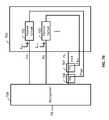
- FIG. 8shows an embodiment of a passive network used in the isolation enhancement network consisting of a filter and an equalizer.
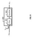
- FIG. 9shows an embodiment of a passive equalizer that includes parallel branches of attenuators, phase shifters, and delay elements.
- FIG. 10shows an embodiment of a passive variable equalizer that includes parallel branches of variable attenuators, variable phase shifters, and variable delay elements.
- FIG. 11shows one application of the RF multiplexer with isolation enhancement in the front-end of a multi-band communication system.
- FIG. 12shows another application of the RF multiplexer with isolation enhancement in the front-end of a multi-band communication system.
- FIG. 13shows another application of the RF multiplexer with isolation enhancement in the front-end of a multi-band communication system.
- FIG. 14shows an embodiment of a controllable multiplexer with isolation enhancement in conjunction with a communication transceiver.
- FIG. 15illustrates an embodiment of a tunable or reconfigurable multiplexer with a tunable or reconfigurable isolation enhancement network.
- FIG. 16shows an embodiment of a tunable or reconfigurable multiplexer with a tunable or reconfigurable isolation enhancement in conjunction with a communication transceiver.
- FIG. 17shows another application of the RF multiplexer with isolation enhancement in the front-end of a multi-band communication system.
- FIG. 18shows an embodiment of an N ⁇ M RF multiplexer with N input and N ⁇ M output ports.
- FIG. 19shows an embodiment of an N ⁇ M RF multiplexer with isolation enhancement network with N input and N ⁇ M output ports.
- FIG. 20shows an embodiment of an N ⁇ M RF multiplexer with isolation enhancement network in the front-end of a multi-band communication system that supports N antenna ports and N ⁇ M transmit/receive ports.
- FIG. 21shows an embodiment of an RF multiplexer with isolation enhancement network.
- FIG. 22shows an embodiment of a radio frequency front-end of a two-antenna FDD scheme with isolation enhancement.
- circuitand “circuitry” refer to physical electronic components (i.e. hardware) and any software and/or firmware (“code”) which may configure the hardware, be executed by the hardware, and/or otherwise be associated with the hardware.
- codesoftware and/or firmware
- “and/or”means any one or more of the items in the list joined by “and/or”.
- x and/or ymeans any element of the three-element set ⁇ (x), (y), (x, y) ⁇ .
- x, y, and/or zmeans any element of the seven-element set ⁇ (x), (y), (z), (x, y), (x, z), (y, z), (x, y, z) ⁇ .
- the term “exemplary”means serving as a non-limiting example, instance, or illustration.
- the terms “e.g.,” and “for example”set off lists of one or more non-limiting examples, instances, or illustrations.
- Relational terms such as “first” and “second” and the likemay be used solely to distinguish one entity or action from another, without necessarily requiring or implying any actual relationship or order between them.
- the terms “comprises,” “comprising,” and any other variation thereof when used in connection with a list of elements in the specification or claimsare intended to indicate that the list is not exclusive and that other elements may be included.
- an element preceded by an “a” or an “an”does not, without further constraints, preclude the existence of additional elements of the identical type.
- the disclosurehas application in multi-band, multi-standard, and multi-function wireless communication systems. For instance, it can be configured to support carrier aggregation in a wireless communication standard. It can be configured to support frequency division duplex communication system. It can be applied to hand-portable platforms such as smartphones, tablets, cell phones, laptops, etc. that support wireless communications. The disclosure can also be applied to wireless communication base stations, including micro-, pico-, and femto-base stations, repeaters, and signal boosters.
- FIG. 1Aillustrates an embodiment of a frequency multiplexer 100 that enables connecting a number of transmitters 101 , 102 , . . . and receivers 103 , 104 , . . . to one or more common antennas such as a common antenna 105 .
- the transmitters 101 , 102 , . . . and receivers 103 , 104 , . . .need not be separate and may be realized as a single multi-band, multi-standard, or multi-function transceiver.
- FIG. 1Billustrates an embodiment of a frequency multiplexer 110 that enables connecting a number of transmitters 111 , 112 , . . . to one or more common antennas such as a common antenna 113 . It is noted that the transmitters 111 , 112 , . . . need not be separate and may be realized as a single multi-band, multi-standard, or multi-function transmitter.
- FIG. 1Cillustrates an embodiment of a frequency multiplexer 120 that enables connecting a number of receivers 121 , 122 , . . . to one or more common antennas such as a common antenna 123 . It is noted that the receivers 121 , 122 , . . . need not be separate and may be realized as a single multi-band, multi-standard, or multi-function receiver.
- FIG. 2Aillustrates a realization of a frequency multiplexer 200 that enables connecting ports P 1 , P 2 , P 3 , . . . to a common port P 0 .
- the signal path from each port to the common port P 0includes a band-selective filter and an impedance matching network.
- the signal path from port P 1 to the common port P 0includes a band-pass filter 201 and an impedance matching network 204 .
- the signal path from port P 2 to the common port P 0includes a band-pass filter 202 and an impedance matching network 205
- the signal path from port P 3 to the common port P 0includes a band-pass filter 204 and an impedance matching network 206 .
- common port P 0is coupled to an antenna, while ports P 1 , P 2 , P 3 , . . . correspond to transmitter or receiver ports.
- FIG. 2Billustrates a realization of a frequency multiplexer 210 that enables connecting ports P 1 , P 2 , P 3 , . . . to a common port P 0 .
- the signal path from each port to the common port P 0includes a band-selective filter 211 , 212 , 213 , . . . and a common passive network 215 .
- the common passive network 215might be used for impedance matching, enhancing the isolation between various ports or signal paths, providing additional filtering, or other purposes.
- common port P 0is coupled to an antenna, while ports P 1 , P 2 , P 3 , . . . correspond to transmitter or receiver ports.
- the multiplexermay be constructed by a proper combination of duplexers, filters, passive components, etc.
- the isolation enhancement methods covered in this disclosureare applicable to such multiplexers as well.
- FIGS. 3A-3Iillustrate frequency-domain response of a multiplexer.
- the frequency multiplexeris designed to multiplex three different frequency bands designated as Band 1 , Band 2 , and Band 3 , each with a different frequency band and bandwidth.
- FIG. 3Aillustrates the magnitude transfer function between port 1 (P 1 ) and common port 0 (P 0 ) as
- the transfer functionis a band-pass response selecting Band 1 .
- typical frequency multiplexersare passive, the magnitude of the power transfer function between any two ports cannot exceed unity which corresponds to zero in the common decibel units.
- FIG. 3Dillustrates the magnitude transfer function between port 2 (P 2 ) and common port 0 (P 0 ) as
- the transfer functionis a band-pass response selecting Band 2 .
- typical frequency multiplexersare passive, the magnitude of the power transfer function between any two ports cannot exceed unity which corresponds to zero in the common decibel units.
- FIG. 3Gillustrates the magnitude transfer function between port 3 (P 3 ) and common port 0 (P 0 ) as
- the transfer functionis a band-pass response selecting Band 3 .
- typical frequency multiplexersare passive, the magnitude of the power transfer function between any two ports cannot exceed unity which corresponds to zero in the common decibel units.
- FIG. 3Billustrates the desirable regions for the magnitude transfer function between ports 1 and 2 as
- FIG. 3Eillustrates the desirable regions for the magnitude transfer function between ports 2 and 1 as
- will be the same as
- FIG. 3Cillustrates the desirable regions for the magnitude transfer function between ports 1 and 3 as ISA in this frequency multiplexer.
- ports 1 and 3are isolated in both of their corresponding frequency bands Band 1 and Band 3 .
- FIG. 3Hillustrates the desirable regions for the magnitude transfer function between ports 3 and 1 as
- ports 3 and 1are isolated in both of their corresponding frequency bands Band 3 and Band 1 .
- In fact, in a reciprocal network,
- FIG. 3Fillustrates the desirable regions for the magnitude transfer function between ports 2 and 3 as
- FIG. 3Iillustrates the desirable regions for the magnitude transfer function between ports 3 and 2 as
- FIG. 4shows an embodiment of the present disclosure where an isolation enhancement network 401 is connected to a multiplexer 400 so that the mutual isolation between ports P 1 , P 2 , P 3 , P 4 , . . . is enhanced compared with the inherent isolation of the multiplexer ports P′ 1 , P′ 2 , P′ 3 , P′ 4 , . . . .
- FIG. 5shows an embodiment of the present disclosure where an isolation enhancement network 501 is connected to a multiplexer 500 so that the mutual isolation between ports P 1 , P 2 , P 3 , P 4 , . . . is enhanced compared with the inherent isolation of the multiplexer ports P′ 1 , P′ 2 , P′ 3 , P′ 4 , . . .
- Isolation enhancement network 501interfaces with the multiplexer 500 through multiplexer ports P 1 , P 2 , P 3 , P 4 , . . . as well as through coupled portions of the signals on those ports designated as P′ 1 , P′ 2 , P′ 3 , P′ 4 , . . . .
- couplersare designed to transfer most of the power to the Pi ports and less of the power to the P′i ports where i is an integer number corresponding to ports 1 , 2 , 3 , 4 , etc.
- 10 dB couplersmay be used where 90% of the power is transferred to ports Pi and 10% of the power is transferred to ports P′i.
- One advantage of such realizationsis lower insertion loss between the common port P 0 and the multiplexed ports P 1 , P 2 , P 3 , P 4 , etc.
- FIG. 6is an embodiment of an isolation enhancement network 600 that can be used in the configuration shown in FIG. 5 as block 501 .
- a passive circuit 601that has a high input impedance Z in,m , Z in,n , . . . at some frequency range of interest.
- each port Pmmay be low at some other frequency range of interest facilitating power delivery.
- Passive blocks 601 , 602 , etc.are hence designed to provide desired driving point impedance levels at different frequency ranges.
- any of the passive blocks 601 , 602 , etc.may include a passive filter at its input so that it enables power delivery only at filter's passband frequencies.
- FIGS. 7A-7Bshow two embodiments of the present disclosure where isolation enhancement networks are coupled to multiplexers.
- the operation of the isolation enhancement network 701may be explained as in the following.
- Passive circuits 702 , 703 , . . .are designed to have high input impedance at the frequencies corresponding to ports Pm, Pn, . . . . Therefore, for instance, signals at port Pm within the frequency range corresponding to port Pm will primarily enter the multiplexer 700 and do not enter the isolation enhancement network 701 .
- passive network 702is designed in such a way that such a coupled signal cancels the unwanted leakage from port Pm to port Pk (through the nonideal multiplexer 701 ).
- passive circuit 702is designed so that its transfer function combined with that of the coupling network (e.g., passive combiner 704 and coupler 705 in FIG. 7A or coupler 706 in FIG. 7B ) is the same (or very close) to the unwanted leakage transfer function between ports Pm and Pk in the non-ideal multiplier 700 .
- the coupling networke.g., passive combiner 704 and coupler 705 in FIG. 7A or coupler 706 in FIG. 7B
- the passive network 800includes a filter 801 and an equalizer 802 .
- Filter 801may be designed to offer high input impedance, Z in,m , at a frequency range of interest which can be different than the passband of the filter. In fact, if filter 801 is lossless and passive, the input impedance of the filter is reflective within the filter passband.
- Equalizer 802may be designed to modify the amplitude and phase responses at a frequency range of interest which may or may not overlap with the frequency range of interest for which the filter offers high input impedance.
- FIG. 9shows an embodiment of passive equalizer 900 that may include attenuators 901 , 904 , 907 , . . . , phase shifters 902 , 905 , 908 , . . . , and time delays 903 , 906 , 909 , . . . .
- the passive equalizerincludes parallel branches where each branch includes attenuator, phase shifter, and time delay. It is noted that not all paths must include all of the attenuator, phase shifter, and time delay. For instance, one branch may include attenuator and phase shifter. It is also noted that these blocks need not be implemented as separate blocks with only one function.
- amplitude controlattenuator
- phase shiftingand time delay
- these blocksmay achieve their desired function only at a range of frequencies.
- a blockmay offer time delay only at a desired range of frequencies.
- the number of parallel branches in the equalizermay be one or higher to offer equalization across a wider range of frequencies.
- a group delay associated with a narrowband circuit at a frequency band or frequency bands of interestmay be used in realization of the time delay.
- FIG. 10shows an embodiment of a passive equalizer 1000 that may include variable attenuators 1001 , 1004 , 1007 , . . . , variable phase shifters 1002 , 1005 , 1008 , . . . , and variable time delays 1003 , 1006 , 1009 , . . . .
- the passive equalizerincludes parallel branches where each branch includes a variable attenuator, a variable phase shifter, and a variable time delay. It is noted that not all paths must include all of the variable attenuator, the variable phase shifter, and the variable time delay. For instance, one branch may include the variable attenuator and the variable phase shifter. It is noted that not all these blocks must be variable.
- some of the attenuators, phase shifters, and time delaysmay be fixed and some may be variable. It is also noted that these blocks need not be implemented as separate blocks with only one function. For instance, one block may simultaneously achieve two or three functions of the variable amplitude control (attenuator), variable phase shifting, and variable time delay. Furthermore, these blocks may achieve their desired function only at a range of frequencies. For instance, a block may offer variable time delay only at a desired range of frequencies. The number of parallel branches in the equalizer may be set to offer equalization across a wider range of frequencies. Variable blocks might be used to modify the frequency range of interest or to accommodate for wanted or unwanted changes in other circuitry such as temperature.
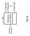
- FIG. 11shows an embodiment of a multiplexer with isolation enhancement 1100 that is used to interface multiple transmit frequency bands, TX Band # 1 , TX Band # 2 , . . . , TX Band #N (N is a positive integer) to a common antenna interface.
- Transmit bandsmay correspond to different transmitters operating at different frequency bands. Some of the transmit bands may correspond to one transmitter that works at more than one frequency band. This scheme may be used, for instance, in a multi-band wireless communication device.
- FIG. 12shows an embodiment of a multiplexer with isolation enhancement 1200 that is used to interface multiple receive frequency bands, RX Band # 1 , RX Band # 2 , . . . , RX Band #M (M is a positive integer) to a common antenna interface.
- Receive bandsmay correspond to different receivers operating at different frequency bands. Some of the receive bands may correspond to one receiver that works at more than one frequency band. This scheme may be used, for instance, in a multi-band wireless communication device.
- FIG. 13shows an embodiment of a multiplexer with isolation enhancement 1300 that is used to interface multiple transmit frequency bands, TX Band # 1 , TX Band # 2 , . . . , TX Band #N, and multiple receive frequency bands RX Band # 1 , RX Band # 2 , . . . , RX Band #M to a common antenna interface.
- Transmit bandsmay correspond to different transmitters operating at different frequency bands. Some of the transmit bands may correspond to one transmitter that works at more than one frequency band. Receive bands may correspond to different receivers operating at different frequency bands. Some of the receive bands may correspond to one receiver that works at more than one frequency band. This scheme may be used, for instance, in a multi-band wireless communication device.
- FIG. 14shows an embodiment of a multiplexer with isolation enhancement 1400 that interfaces with transceiver 1401 .
- Port P 0 of the multiplexer with isolation enhancement 1400may correspond to an antenna interface.
- Ports P 1 , P 2 , P 3 , . . .may correspond to transmit or receive frequency bands.
- Transceivermay send certain information CAL to the multiplexer with isolation enhancement. This information, for instance, may correspond to locations of frequency bands or quality of information captured or processed in the transceiver. This information, for instance, may be applied to the variable blocks of the multiplexer with isolation enhancement. This scheme may be applicable to multi-band communication systems.
- FIG. 15shows an embodiment of a tunable or reconfigurable multiplexer 1500 with tunable or reconfigurable isolation enhancement network 1501 that interface with each other through ports P′ 1 , P′ 2 , P′ 3 , P′ 4 , . . . Port P 0 is the common port of the tunable or reconfigurable multiplexer.
- Tunable or reconfigurable schememay be applicable in multi-band multi-standard communication systems. Tunability or reconfigurability may be in response to a change in the desired frequency bands or standards. It might be in response to desired or undesired changes.
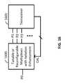
- FIG. 16shows an embodiment of a tunable or reconfigurable multiplexer with isolation enhancement 1600 that interfaces with transceiver 1601 .
- Port P 0 of the multiplexer with isolation enhancement 1600may correspond to an antenna interface.
- Ports P 1 , P 2 , P 3 , . . .may correspond to transmit or receive frequency bands.
- Transceivermay send certain information CAL to the tunable or reconfigurable multiplexer with isolation enhancement. This information, for instance, may correspond to locations of frequency bands or quality of information captured or processed in the transceiver. This information, for instance, may be applied to the variable blocks of the multiplexer with isolation enhancement. This scheme may be applicable to multi-band multi-standard communication systems.
- Tunability or reconfigurabilitymay be in response to a change in the desired frequency bands or standards. It might be in response to desired or undesired changes.
- one or more of the tunable components in the multiplexer 1600may be tuned with an application of at least one electrical stimulus.
- the at least one electrical stimulusmay be provided by the transceiver 1601 according to the information captured by the transceiver 1601 or processed by a signal processor in the transceiver 1601 .
- FIG. 17shows an embodiment of a multiplexer with isolation enhancement 1700 that interfaces a number of transmit and receive frequency bands to a common antenna interface.
- each port of the multiplexer with isolation enhancement 1700may correspond to multiple receive or transmit frequency bands. Frequency bands corresponding to the same port may be adjacent, close, or far from each other. This scheme may facilitate a more effective interface to a transmitter, receive, or transceiver. For instance, multiple bands may be more effectively interfaced with a single amplifier in the receiver or transmitter paths.
- FIG. 18shows an embodiment of a multiplexer 1800 that interfaces multiple common ports P 1 , P 2 , . . . to a set of other ports P 11 , P 12 , . . . , P 1 N, and P 21 , P 22 , . . . , P 2 M, and . . . .
- This schememay be applicable, for instance, to a multi-antenna communication system where each common port P 1 , P 2 , . . . corresponds to an antenna interface.
- Ports P 11 , P 12 , . . . , P 1 Nmay correspond to information at bands 1 , 2 , . . . , N, respectively, intended for port P 1 .
- Ports P 21 , P 22 , . . . , P 2 Mmay correspond to information at bands 1 , 2 , . . . , M, respectively, intended for port P 2 .
- the isolation between any two pair of the information bands (P 11 , P 12 , . . . , P 1 N, P 21 , P 22 , . . . , P 2 M), whether they correspond to the same antenna or not,should be high. Therefore, the proposed isolation enhancement scheme may be applied to all pairs of information bands.
- FIG. 19shows an embodiment of a multiplexer 1900 that couples to isolation enhancement network 1901 through ports P′ 11 , P′ 12 , . . . , PIN, P′ 21 , P′ 22 , . . . , P′ 2 M, . . . .
- This schememay be applicable, for instance, to a multi-antenna communication system where each port P 1 , P 2 , . . . corresponds to an antenna interface.
- Ports P 11 , P 12 , . . . , P 1 Nmay correspond to information at bands 1 , 2 , . . . , N, respectively, intended for port P 1 .
- P 2 Mmay correspond to information at bands 1 , 2 , . . . , M, respectively, intended for port P 2 .
- the isolation enhancement network 1901enhances the isolation not only between ports that correspond to each antenna interface port, but also between ports that correspond to different antenna interface ports. It should be noted that the requirements for the building blocks that enhance the isolation between the ports corresponding to the same antenna may be very different compared to those corresponding to different antennas. For instance, a common leakage path between ports corresponding to different antenna is through the electromagnetic radiation (antenna coupling). An unwanted leakage signal through this path may undergo a large propagation delay that may lead to the requirement for large time delay blocks in the isolation enhancement block. It is noted that multiplexer 1900 may be constructed of individual blocks.
- multiplexer 1900may be constructed out of a few duplexers.
- isolation enhancement network 1901may be constructed of individual blocks.
- a two antenna FDD systemsuch as a 2 ⁇ 2 multi input multi output (MIMO) FDD scheme.
- MIMOmulti input multi output
- Such a systemmay have two antennas coupled to two transceivers (or a 2 ⁇ 2 MIMO transceiver).
- MIMOmulti input multi output
- a separate duplexermay be used for each of the two antennas. While the isolation between the transmit and receive ports of each duplexer may be sufficient; but, the signals from a transmitter corresponding to either antenna may leak to the receiver corresponding to the other antenna. This unwanted coupling may be through the air (antenna coupling).
- the isolation enhancement networkshould compensate for such unwanted leakage to ensure sufficient isolation between each transmitter and both receivers.
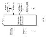
- FIG. 20illustrates an embodiment of multiplexer with isolation enhancement 2000 that interfaces with antenna interface ports designated as Antenna Interface 1 , Antenna Interface 2 , . . . and a number of transmit/receive ports designated as TX/RX Band # 1 , TX/RX Band # 2 , . . . , TX/RX Band #P, corresponding to Antenna Interface 1 , TX/RX Band # 1 , TX/RX Band # 2 , . . . , TX/RX Band # 0 , corresponding to Antenna Interface 2 , . . . .
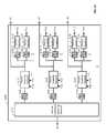
- FIG. 21illustrates an embodiment of a multiplexer with isolation enhancement 2100 that interfaces common port P 0 with ports P 1 , P 2 , P 3 , . . . .
- the multiplexerincludes band-select filters 2110 , 2120 , 2130 , . . . , each corresponding to a specific range of frequencies.
- a general passive networke.g., passive impedance matching network 2101
- This network 2101may improve impedance matching, enhance isolation, provide additional filtering, etc.
- Isolation enhancementis applied to ports P 1 , P 2 , P 3 , . . . .
- Each portinterfaces with other ports through parallel combination of filters and equalizers.
- port P 1interfaces with port P 2 through filter 2120 _ 1 and passive equalizer 2112 , and ultimately a passive coupling network 2121 .
- filter 2120 _ 1may be designed to have a similar or substantially the same frequency response as filter 2120 .
- Passive equalizer 2112may be designed to align the signals in the cancellation paths in phase, amplitude, and delay with the originally leaked signal between ports P 1 and P 2 at frequency range of interest.
- port P 1interfaces with port P 2 through filter 2130 _ 1 and passive equalizer 2113 , and ultimately a passive coupling network 2131 .
- filter 2130 _ 1may be designed to have a similar or substantially the same frequency response as filter 2130 .
- Passive equalizer 2113may be designed to align the signals in the cancellation paths in phase, amplitude, and delay with the originally leaked signal between ports P 1 and P 3 at frequency range of interest. Similar isolation enhancement paths between other ports are also included.
- all components in the multiplex 2100may be integrated in a single package.
- the multiplexer 2100may be integrated with one or more of the following in the same package: one or more radio frequency amplifiers, one or more radio frequency switches, one or more radio frequency filters, and one or more other radio frequency multiplexers.
- FIG. 22illustrates an embodiment of an radio frequency front-end 2200 of a two-antenna FDD scheme with isolation enhancement.
- the RF front-end 2200interfaces with two antenna interfaces, namely, antenna interface 1 and antenna interface 2 , to two pairs of transmit and receive ports specified as TX 1 , RX 1 , TX 2 , and RX 2 .
- this front-end 2200may be applied to a 2 ⁇ 2 MIMO scheme that supports frequency division duplexing.
- frequency duplexers 2201 and 2202provide sufficient isolation between their transmit and receive ports. In other words, there is sufficient isolation between ports TX 1 and RX 1 of duplexer 2201 , and there is sufficient isolation between ports TX 2 and RX 2 of duplexer 2202 .
- Isolation enhancement networkswhich comprise filters 2203 and 2205 , and passive equalizers 2204 and 2206 enhance the isolation between these ports.
- Filters 2203 and 2205offer high input impedances (Z in,1 and Z in,2 ) at the transmit frequencies and low input impedance at the receive frequencies.
- Passive equalizers 2204 and 2206ensure that the transfer function of the cancellation paths is similar (or very close) to that of the leakage paths at the receive frequencies. More networks may be added between the ports to enhance the isolation further and at different frequencies.
- the schemeneed not have identical features or topologies with respect to various ports.
- the number and topologies of filters, passive equalizers, and passive coupling networksneed not be the same for different ports P 1 , P 2 , P 3 , . . . .
- the inherent isolation between various multiplexer portsmay be different among different ports, requiring different levels of enhancement.
- the required isolation between various portsmay be different and application- or standard-dependent.
- active componentsmay be used in filters, equalizers, impedance matching networks, and coupling networks.
- variable componentsmay include active components to enable tunability or reconfigurability.
- inventions of the disclosuremay provide a non-transitory computer readable medium and/or storage medium, and/or a non-transitory machine readable medium and/or storage medium, having stored thereon, a machine code and/or a computer program having at least one code section executable by a machine and/or a computer, thereby causing the machine and/or computer to perform the steps as described herein for enhancing isolation in RF multiplexers.
- aspects of the present disclosuremay be realized in hardware, software, or a combination of hardware and software.
- the present disclosuremay be realized in a centralized fashion in at least one computer system or in a distributed fashion where different elements are spread across several interconnected computer systems. Any kind of computer system or other apparatus adapted for carrying out the methods described herein is suited.
- a typical combination of hardware and softwaremay be a general-purpose computer system with a computer program that, when being loaded and executed, controls the computer system such that it carries out the methods described herein.
- Computer program in the present contextmeans any expression, in any language, code or notation, of a set of instructions intended to cause a system having an information processing capability to perform a particular function either directly or after either or both of the following: a) conversion to another language, code or notation; b) reproduction in a different material form.
Landscapes
- Engineering & Computer Science (AREA)
- Computer Networks & Wireless Communication (AREA)
- Signal Processing (AREA)
- Physics & Mathematics (AREA)
- Mathematical Physics (AREA)
- Power Engineering (AREA)
- Transceivers (AREA)
Abstract
Description
Claims (20)
Priority Applications (1)
| Application Number | Priority Date | Filing Date | Title |
|---|---|---|---|
| US15/220,181US10581650B2 (en) | 2015-09-08 | 2016-07-26 | Enhancing isolation in radio frequency multiplexers |
Applications Claiming Priority (2)
| Application Number | Priority Date | Filing Date | Title |
|---|---|---|---|
| US201562215450P | 2015-09-08 | 2015-09-08 | |
| US15/220,181US10581650B2 (en) | 2015-09-08 | 2016-07-26 | Enhancing isolation in radio frequency multiplexers |
Publications (2)
| Publication Number | Publication Date |
|---|---|
| US20170070405A1 US20170070405A1 (en) | 2017-03-09 |
| US10581650B2true US10581650B2 (en) | 2020-03-03 |
Family
ID=58189638
Family Applications (1)
| Application Number | Title | Priority Date | Filing Date |
|---|---|---|---|
| US15/220,181ActiveUS10581650B2 (en) | 2015-09-08 | 2016-07-26 | Enhancing isolation in radio frequency multiplexers |
Country Status (1)
| Country | Link |
|---|---|
| US (1) | US10581650B2 (en) |
Cited By (1)
| Publication number | Priority date | Publication date | Assignee | Title |
|---|---|---|---|---|
| US20210091751A1 (en)* | 2019-09-19 | 2021-03-25 | Skyworks Solutions, Inc. | Multiplexer with reduced phase spreading |
Families Citing this family (16)
| Publication number | Priority date | Publication date | Assignee | Title |
|---|---|---|---|---|
| US10547336B2 (en)* | 2015-10-23 | 2020-01-28 | Qorvo Us, Inc. | Radio frequency circuitry for carrier aggregation |
| US10560867B2 (en) | 2016-12-29 | 2020-02-11 | Qorvo Us, Inc. | Reducing intermodulation distortion in a radio frequency circuit |
| US10587292B2 (en)* | 2018-04-27 | 2020-03-10 | Avago Technologies International Sales Pte. Limited | Multiplexer with switched filter branch including high-Q components |
| US11374549B2 (en) | 2018-06-15 | 2022-06-28 | Resonant Inc. | Filter using transversely-excited film bulk acoustic resonators with divided frequency-setting dielectric layers |
| CN109462741B (en)* | 2018-12-12 | 2020-12-29 | 航天恒星空间技术应用有限公司 | Multi-band digital image transmission terminal |
| CN110212926A (en)* | 2019-06-27 | 2019-09-06 | 博为科技有限公司 | A kind of signal processing apparatus |
| WO2021142125A1 (en)* | 2020-01-08 | 2021-07-15 | Formfactor, Inc. | Beamforming device testing |
| EP4179629B1 (en)* | 2020-07-08 | 2025-09-03 | Telefonaktiebolaget LM ERICSSON (PUBL) | Duplexer, multiplexer and multiband filter |
| US11343125B2 (en)* | 2020-07-08 | 2022-05-24 | Huawei Technologies Co., Ltd. | Multiplexer with embedded equalization |
| US11405017B2 (en)* | 2020-10-05 | 2022-08-02 | Resonant Inc. | Acoustic matrix filters and radios using acoustic matrix filters |
| US11658639B2 (en) | 2020-10-05 | 2023-05-23 | Murata Manufacturing Co., Ltd. | Transversely-excited film bulk acoustic resonator matrix filters with noncontiguous passband |
| US11405019B2 (en) | 2020-10-05 | 2022-08-02 | Resonant Inc. | Transversely-excited film bulk acoustic resonator matrix filters |
| US11476834B2 (en) | 2020-10-05 | 2022-10-18 | Resonant Inc. | Transversely-excited film bulk acoustic resonator matrix filters with switches in parallel with sub-filter shunt capacitors |
| US11929733B2 (en) | 2020-10-05 | 2024-03-12 | Murata Manufacturing Co., Ltd. | Transversely-excited film bulk acoustic resonator matrix filters with input and output impedances matched to radio frequency front end elements |
| US11728784B2 (en) | 2020-10-05 | 2023-08-15 | Murata Manufacturing Co., Ltd. | Transversely-excited film bulk acoustic resonator matrix filters with split die sub-filters |
| CN114500277B (en)* | 2021-12-15 | 2023-12-05 | 三维通信股份有限公司 | Parameter configuration method and device for multi-band radio frequency chip and electronic device |
Citations (154)
| Publication number | Priority date | Publication date | Assignee | Title |
|---|---|---|---|---|
| US2561212A (en) | 1949-12-15 | 1951-07-17 | Bell Telephone Labor Inc | Microwave hybrid branching systems |
| US3025463A (en) | 1957-11-22 | 1962-03-13 | Eino J Luoma | Apparatus for measurement of complex reflection coefficient |
| US3453638A (en) | 1966-03-22 | 1969-07-01 | Communications Inc | Multiplex package |
| US3704409A (en) | 1971-05-24 | 1972-11-28 | Avco Corp | Digital reflection coefficient detector |
| US3800218A (en) | 1973-02-07 | 1974-03-26 | Jerrold Electronics Corp | R. f. impedance bridge for measuring reflection coefficient |
| US4029902A (en) | 1975-10-22 | 1977-06-14 | Hughes Aircraft Company | Contiguous channel multiplexer |
| US4146851A (en) | 1977-06-23 | 1979-03-27 | Gte Laboratories Incorporated | Acoustic surface wave device |
| US4427936A (en) | 1981-06-22 | 1984-01-24 | Microwave Development Labs | Reflection coefficient measurements |
| US4464675A (en) | 1982-08-04 | 1984-08-07 | Rca Corporation | Low frequency digital comb filter system |
| US4489271A (en) | 1979-01-15 | 1984-12-18 | Riblet Gordon P | Reflection coefficient measurements |
| US4694266A (en) | 1986-07-29 | 1987-09-15 | R. F. Monolithic, Inc. | Notch filter |
| US4721901A (en) | 1986-03-24 | 1988-01-26 | Hercules Incorporated | Method and apparatus for reflection coefficient measurements |
| US4963945A (en) | 1989-04-07 | 1990-10-16 | Plessey Electronic Systems Corp. | Band rejection filtering arrangement |
| US4964945A (en) | 1988-12-09 | 1990-10-23 | Minnesota Mining And Manufacturing Company | Lift off patterning process on a flexible substrate |
| US4968967A (en) | 1988-10-14 | 1990-11-06 | U.S. Philips Corporation | Continuously transmitting and receiving radar |
| US5408690A (en) | 1990-10-01 | 1995-04-18 | Murata Mfg. Co., Ltd. | Antenna supervising apparatus comprising a standing wave ratio measuring unit |
| WO1995015018A1 (en) | 1993-11-24 | 1995-06-01 | Filtronic Comtek Plc | Hybrid notch filter |
| US5483248A (en) | 1993-08-10 | 1996-01-09 | Hughes Aircraft Company | Continuous transverse stub element devices for flat plate antenna arrays |
| US5493246A (en) | 1994-09-06 | 1996-02-20 | Motorola, Inc. | Circuit and method of canceling leakage current in an analog array |
| US5525945A (en) | 1994-01-27 | 1996-06-11 | Martin Marietta Corp. | Dielectric resonator notch filter with a quadrature directional coupler |
| US5574400A (en) | 1994-03-31 | 1996-11-12 | Nec Corporation | Feedforward amplifier with reduced distortion in wide band |
| US5691978A (en) | 1995-04-07 | 1997-11-25 | Signal Science, Inc. | Self-cancelling full-duplex RF communication system |
| US5781084A (en) | 1993-12-15 | 1998-07-14 | Filtronic Comtek Plc | Microwave reflection filter including a ladder network of resonators having progressively smaller Q values |
| US6178310B1 (en) | 1996-12-30 | 2001-01-23 | Lg Information & Communications, Ltd. | Transmitting and receiving antenna voltage standing wave ratios measuring circuit of base station in mobile communication system |
| US6194980B1 (en) | 1999-05-19 | 2001-02-27 | Rockwell Collins, Inc. | Quadrature hybrid RF combining system |
| EP1091497A1 (en) | 1999-08-24 | 2001-04-11 | Telefonaktiebolaget L M Ericsson (Publ) | Transmitter leakage cancellation circuit for co-located GPS receiver |
| US6229992B1 (en) | 1994-11-15 | 2001-05-08 | University Of Bristol | Full-duplex radio transmitter/receiver |
| US6262637B1 (en) | 1999-06-02 | 2001-07-17 | Agilent Technologies, Inc. | Duplexer incorporating thin-film bulk acoustic resonators (FBARs) |
| US6297711B1 (en) | 1992-08-07 | 2001-10-02 | R. A. Miller Industries, Inc. | Radio frequency multiplexer for coupling antennas to AM/FM/WB, CB/WB, and cellular telephone apparatus |
| US20020089396A1 (en) | 2001-01-11 | 2002-07-11 | Kazushige Noguchi | Saw filter with an attenuation pole including a band-pass ladder type of saw filter having a saw resonator |
| US6496061B1 (en) | 2000-10-10 | 2002-12-17 | Conexant Systems, Inc. | High efficiency multiple power level amplifier |
| US20030109077A1 (en) | 2001-12-07 | 2003-06-12 | Samsung Electro-Mechanics Co., Ltd. | Method for fabricating surface acoustic wave filter packages |
| US20040000425A1 (en) | 2002-06-26 | 2004-01-01 | White George E. | Methods for fabricating three-dimensional all organic interconnect structures |
| US6721544B1 (en)* | 2000-11-09 | 2004-04-13 | Intel Corporation | Duplexer structure for coupling a transmitter and a receiver to a common antenna |
| US20040127178A1 (en) | 2002-12-30 | 2004-07-01 | Motorola, Inc. | Tunable duplexer |
| US20040152426A1 (en)* | 2002-11-08 | 2004-08-05 | Tdk Corporation | Front-end module and communication terminal |
| US20040180633A1 (en) | 2002-12-18 | 2004-09-16 | Toshifumi Nakatani | Radio communication apparatus, radio communication method, antenna apparatus and first duplexer |
| US6819302B2 (en) | 2003-01-15 | 2004-11-16 | Lockheed Martin Corporation | Dual port helical-dipole antenna and array |
| US20050070232A1 (en) | 2003-09-26 | 2005-03-31 | Phil Mages | Systems and methods that employ a balanced duplexer |
| US6946847B2 (en) | 2002-02-08 | 2005-09-20 | Daihen Corporation | Impedance matching device provided with reactance-impedance table |
| US20050245213A1 (en) | 2004-04-28 | 2005-11-03 | Takayuki Hirano | Communication apparatus |
| US20050289632A1 (en) | 2004-06-01 | 2005-12-29 | Brooks Paul D | Controlled isolation splitter apparatus and methods |
| US20060019611A1 (en) | 2004-07-21 | 2006-01-26 | Nokia Corporation | Distributed balanced duplexer |
| US7072614B1 (en) | 1999-06-07 | 2006-07-04 | Kasperkovitz Wolfdietrich Geor | Communication device |
| US7116966B2 (en) | 2002-09-13 | 2006-10-03 | Murata Manufacturing Co., Ltd. | Transmitting/receiving filter device and communication device |
| US20070105509A1 (en) | 2005-11-09 | 2007-05-10 | Texas Instruments Inc. | RF transmission leakage mitigator, method of mitigating an RF transmission leakage and CDMA tranceiver employing the same |
| US7250830B2 (en) | 2004-12-30 | 2007-07-31 | M/A Com Inc. | Dual band full duplex mobile radio |
| US7283793B1 (en) | 2002-05-15 | 2007-10-16 | Broadcom Corporation | Package filter and combiner network |
| US7330500B2 (en) | 2001-12-07 | 2008-02-12 | Socovar S.E.C. | Adjustable electronic duplexer |
| US7369811B2 (en) | 2004-04-30 | 2008-05-06 | Wj Communications, Inc. | System and method for sensitivity optimization of RF receiver using adaptive nulling |
| US20080128901A1 (en) | 2006-11-30 | 2008-06-05 | Peter Zurcher | Micro-electro-mechanical systems device and integrated circuit device integrated in a three-dimensional semiconductor structure |
| US20080227409A1 (en) | 2007-03-13 | 2008-09-18 | Qualcomm Incorporated | Wireless receiver with notch filter to reduce effects of transmit signal leakage |
| US20080240000A1 (en) | 2007-03-28 | 2008-10-02 | Kidd Phillip Clifford | System and method for radio operation in umts bands i and iv utilizing a single receiving port |
| US20080261519A1 (en) | 2006-03-16 | 2008-10-23 | Cellynx, Inc. | Dual cancellation loop wireless repeater |
| US20090054008A1 (en) | 2005-01-31 | 2009-02-26 | Matsushita Electric Industrial Co., Ltd. | Multimode communication apparatus |
| US20090125253A1 (en) | 2007-11-08 | 2009-05-14 | Triasx Pty Ltd. | Passive intermodulation test apparatus |
| US20090121797A1 (en) | 2007-08-22 | 2009-05-14 | Chris Karabatsos | High Frequency Digital Oscillator-on-Demand with Synchronization |
| US20090253385A1 (en) | 2008-04-08 | 2009-10-08 | Paul Wilkinson Dent | System and Method for Adaptive Antenna Impedance Matching |
| US20090252252A1 (en) | 2008-04-07 | 2009-10-08 | Qualcomm Incorporated | Highly linear embedded filtering passive mixer |
| US7623005B2 (en) | 2005-05-11 | 2009-11-24 | Telefonaktiebolaget L M Ericsson (Publ) | Filter combiner |
| US20090289744A1 (en) | 2008-05-22 | 2009-11-26 | Kevin Miyashiro | Electronically tunable, absorptive, low-loss notch filter |
| US7633435B2 (en) | 2004-08-24 | 2009-12-15 | Bae Systems Information And Electronic Systems Integration Inc. | Duplexer for simultaneous transmit and receive radar systems |
| US7636388B2 (en) | 2004-07-01 | 2009-12-22 | Broadcom Corporation | Channel fault detection for channel diagnostic systems |
| US20100002620A1 (en) | 2006-09-01 | 2010-01-07 | Qualcomm Incorporated | Repeater having dual receiver or transmitter antenna configuration with adaptation for increased isolation |
| US20100084146A1 (en) | 2008-10-08 | 2010-04-08 | Smith International, Inc. | Ball seat sub |
| US7711329B2 (en) | 2003-11-12 | 2010-05-04 | Qualcomm, Incorporated | Adaptive filter for transmit leakage signal rejection |
| US20100109771A1 (en) | 2007-02-23 | 2010-05-06 | Hynix Semiconductor, Inc. | Repeating system and method for cancellation of feedback interference signal with pre-distortion function |
| US20100127795A1 (en) | 2007-05-29 | 2010-05-27 | Thomas Bauer | Multiband Filter |
| US20100134700A1 (en) | 2007-06-28 | 2010-06-03 | Jean-Luc Robert | Channel filter, in particular for a digital television receiver |
| US20100148886A1 (en) | 2007-12-18 | 2010-06-17 | Fujitsu Limited | Duplexer, module including a duplexer and communication apparatus |
| US20100177917A1 (en) | 2008-12-23 | 2010-07-15 | Gn Resound A/S | Adaptive feedback gain correction |
| US7804383B2 (en) | 2006-08-28 | 2010-09-28 | Stmicroelectronics Sa | Coupled lamb wave resonators filter |
| KR20100134324A (en) | 2009-06-15 | 2010-12-23 | 엘지이노텍 주식회사 | Bandpass Filters and Band Cutoff Filters |
| US20100323654A1 (en) | 2009-06-23 | 2010-12-23 | Qualcomm Incorporated | High dynamic range receiver front-end with q-enhancement |
| US7894779B2 (en) | 2006-06-22 | 2011-02-22 | Honeywell International Inc. | Apparatus and method for transmitting and receiving multiple radio signals over a single antenna |
| US20110069644A1 (en) | 2009-09-21 | 2011-03-24 | Kmw Inc. | Apparatus for Sharing a Wireless Communication Base Station |
| US20110080229A1 (en) | 2009-10-01 | 2011-04-07 | Peter Kenington | Filtering device and a method for filtering a signal |
| US20110080856A1 (en) | 2009-10-01 | 2011-04-07 | Peter Kenington | Duplexer and method for separating a transmit signal and a receive signal |
| US20110134810A1 (en) | 2009-12-07 | 2011-06-09 | Hitachi Media Electronics Co., Ltd. | Module for use in mobile communication terminal and mobile communication terminal applying the same therein |
| US20110140803A1 (en) | 2009-11-02 | 2011-06-16 | Kmw Inc. | Radio Frequency Filter |
| US20110227664A1 (en) | 2008-12-01 | 2011-09-22 | Nortel Networks Limited | Frequency Agile Filter Using a Digital Filter and Bandstop Filtering |
| US20110256857A1 (en) | 2010-04-20 | 2011-10-20 | Intersil Americas Inc. | Systems and Methods for Improving Antenna Isolation Using Signal Cancellation |
| US20120007605A1 (en) | 2008-12-08 | 2012-01-12 | Johannes Benedikt | High frequency measurement system |
| US8135348B2 (en) | 2007-03-27 | 2012-03-13 | Qualcomm, Incorporated | Rejection of transmit signal leakage in wireless communication device |
| US20120063496A1 (en) | 2010-09-13 | 2012-03-15 | Renesas Electronics Corporation | Wireless Transmitters |
| US20120075069A1 (en) | 2010-09-23 | 2012-03-29 | North Carolina State University | Reversibly deformable and mechanically tunable fluidic antennas |
| US8149742B1 (en) | 2009-06-26 | 2012-04-03 | Rockwell Collins, Inc. | System and method for receiving and transmitting signals |
| US20120140860A1 (en) | 2010-12-01 | 2012-06-07 | Qualcomm Incorporated | Non-linear adaptive scheme for cancellation of transmit out of band emissions |
| US8199681B2 (en) | 2008-12-12 | 2012-06-12 | General Electric Company | Software radio frequency canceller |
| US20120154071A1 (en) | 2010-12-21 | 2012-06-21 | Avago Technologies Wireless IP ( Singapore) Pte. Ltd. | Combined balun and imedance matching circuit |
| US20120163245A1 (en) | 2010-12-24 | 2012-06-28 | Hitachi Media Electronics Co., Ltd. | Module for mobile communication terminal and mobile communication terminal |
| US20120161784A1 (en) | 2009-06-05 | 2012-06-28 | Mesuro Limited | High frequency measurement apparatus and method with load pull |
| US20120194269A1 (en) | 2011-02-01 | 2012-08-02 | Hiercomm, Inc. | Passive amplifier |
| US20120201153A1 (en) | 2011-02-03 | 2012-08-09 | Dinesh Bharadia | Adaptive techniques for full duplex communications |
| US20120212304A1 (en) | 2011-02-18 | 2012-08-23 | Cemin Zhang | Absorptive tunable bandstop filter with wide tuning range and electrically tunable all-pass filter useful therein |
| US20120230227A1 (en) | 2011-03-09 | 2012-09-13 | Holger Weiss | Filter arrangement |
| US20130016634A1 (en) | 2011-07-12 | 2013-01-17 | Telefonaktiebolaget L M Ericsson (Publ) | Electronic duplexer |
| US20130063299A1 (en) | 2010-02-16 | 2013-03-14 | Cavitid Inc. | Systems, Methods and Apparatuses for Remote Device Detection |
| US20130065542A1 (en) | 2010-02-16 | 2013-03-14 | Cavitid, Inc., | Spectral Filtering Systems |
| US20130079641A1 (en) | 2008-05-27 | 2013-03-28 | Volusonics Medical Imaging Ltd. | Ultrasound garment |
| US20130083703A1 (en) | 2011-10-04 | 2013-04-04 | Rf Micro Devices, Inc. | Tunable duplexer architecture |
| US8422412B2 (en) | 2009-04-29 | 2013-04-16 | Quellan, Inc. | Duplexer and switch enhancement |
| US20130109330A1 (en) | 2011-10-26 | 2013-05-02 | Qualcomm Incorporated | Impedance balancing for transmitter to receiver rejection |
| US20130113576A1 (en) | 2011-11-04 | 2013-05-09 | Taiyo Yuden Co., Ltd. | Duplexer, filter and communication module |
| US20130130619A1 (en) | 2010-04-26 | 2013-05-23 | Astrium Limited | Dual n-port mpa |
| US20130154887A1 (en) | 2011-12-15 | 2013-06-20 | Paul W. Hein | Antenna testing enclosures and methods for testing antenna systems therewith |
| US20130201880A1 (en) | 2012-02-07 | 2013-08-08 | Rf Micro Devices, Inc. | Tunable duplexer architecture |
| US8514035B2 (en) | 2009-12-30 | 2013-08-20 | Broadcom Corporation | RF front-end with on-chip transmitter/receiver isolation using a gyrator |
| US20130222059A1 (en) | 2012-02-28 | 2013-08-29 | Telefonaktiebolaget L M Ericsson (Publ) | Fir/iir filter predistorter for power amplifiers exhibiting short-term and/or long-term memory effects |
| US20130245976A1 (en) | 2012-03-19 | 2013-09-19 | Telefonaktiebolaget L M Ericsson (Publ) | Measurement of Voltage Standing Wave Ratio of Antenna System |
| US20130242809A1 (en) | 2011-12-16 | 2013-09-19 | Hitachi Media Electronics Co., Ltd. | Mobile communication terminal module and mobile communication terminal |
| US20130241669A1 (en) | 2012-03-14 | 2013-09-19 | Broadcom Corporation | Adjustable duplexer system |
| US20130241655A1 (en) | 2012-03-19 | 2013-09-19 | Auriga Measurement Systems, LLC | Linearization Circuit and Related Techniques |
| US20130301488A1 (en) | 2012-02-08 | 2013-11-14 | The Board Of Trustees Of The Leland Stanford Junior University | Systems and methods for cancelling interference using multiple attenuation delays |
| US8600329B1 (en) | 2012-10-04 | 2013-12-03 | Raytheon Company | Interference signal canceller |
| US20130321097A1 (en) | 2012-05-29 | 2013-12-05 | Rf Micro Devices, Inc. | Vswr tolerant tunable hybrid duplexer |
| US8620246B2 (en) | 2006-01-14 | 2013-12-31 | Blackberry Limited | Adaptive impedance matching module (AIMM) control architectures |
| DE102012107877A1 (en) | 2012-08-27 | 2014-02-27 | Epcos Ag | duplexer |
| US20140103946A1 (en) | 2012-10-12 | 2014-04-17 | National Instruments Ireland Resources Limited | Device for Actively Improved Impedance Synthesis |
| EP2733855A1 (en) | 2012-11-15 | 2014-05-21 | Telefonaktiebolaget L M Ericsson (publ) | Transceiver front-end |
| US20140169236A1 (en) | 2012-12-13 | 2014-06-19 | Kumu Networks | Feed forward signal cancellation |
| US8761026B1 (en) | 2013-04-25 | 2014-06-24 | Space Systems/Loral, Llc | Compact microstrip hybrid coupled input multiplexer |
| US20140194073A1 (en) | 2013-01-04 | 2014-07-10 | Telefonaktiebolaget L M Ericsson (Publ) | Digital suppression of transmitter intermodulation in receiver |
| US20140204808A1 (en) | 2013-01-18 | 2014-07-24 | Kumu Networks | Tuning algorithm for multi-tap signal cancellation circuit |
| WO2014133625A2 (en) | 2012-12-11 | 2014-09-04 | University Of Southern California | Passive leakage cancellation networks for duplexers and coexisting wireless communication systems |
| US20140348018A1 (en) | 2011-02-03 | 2014-11-27 | The Board Of Trustees Of The Leland Stanford Junior University | Self-interference cancellation |
| EP2814172A1 (en) | 2013-06-10 | 2014-12-17 | Alcatel Lucent | Filter for RF applications |
| US8957742B2 (en) | 2008-09-24 | 2015-02-17 | Blackberry Limited | Methods for tuning an adaptive impedance matching network with a look-up table |
| US20150049841A1 (en) | 2013-05-22 | 2015-02-19 | Telefonaktiebolaget L M Ericsson (Publ) | Linearization of intermodulation bands for concurrent dual-band power amplifiers |
| US20150118978A1 (en) | 2013-10-25 | 2015-04-30 | Rf Micro Devices, Inc. | Transmit and receive rf multiplexer |
| US20150163044A1 (en) | 2013-12-10 | 2015-06-11 | University Of Southern California | Enhancing Isolation and Impedance Matching in Hybrid-Based Cancellation Networks and Duplexers |
| US20150236842A1 (en) | 2014-02-14 | 2015-08-20 | University Of Southern California | Hybrid-based cancellation in presence of antenna mismatch |
| US20150236395A1 (en) | 2014-02-14 | 2015-08-20 | University Of Southern California | Reflection and hybrid reflection filters |
| US20150236390A1 (en) | 2014-02-19 | 2015-08-20 | University Of Southern California | Miniature acoustic resonator-based filters and duplexers with cancellation methodology |
| US20150295697A1 (en)* | 2014-04-10 | 2015-10-15 | Taiyo Yuden Co., Ltd. | Multiplexer |
| US20150295559A1 (en)* | 2014-04-09 | 2015-10-15 | Avago Technologies General Ip (Singapore) Pte. Ltd. | Multiplexer using multiple tuned output impedances for reduced harmonic generation |
| US9214718B2 (en) | 2012-03-08 | 2015-12-15 | Apple Inc. | Methods for characterizing tunable radio-frequency elements |
| EP2960981A1 (en) | 2013-02-19 | 2015-12-30 | Osaka Prefecture University Public Corporation | Waveguide-type image rejection filter, single-sideband receiver utilizing same, frequency divider, and sideband-separating receiver |
| US20160050031A1 (en) | 2014-08-14 | 2016-02-18 | Qualcomm Incorporated | Automated blind coefficient control in analog active interference cancellation |
| WO2016063108A1 (en) | 2014-10-21 | 2016-04-28 | Telefonaktiebolaget L M Ericsson (Publ) | Radio frequency multiplexer |
| US20160134325A1 (en) | 2013-06-18 | 2016-05-12 | Telefonaktiebolaget L M Ericsson (Publ) | A duplex unit |
| US9379920B1 (en)* | 2015-05-08 | 2016-06-28 | Xilinx, Inc. | Decision feedback equalization with precursor inter-symbol interference reduction |
| US20160204821A1 (en) | 2015-01-13 | 2016-07-14 | Apple Inc. | Electronic Device With Impedance Measurement Circuitry |
| US20160211870A1 (en) | 2015-01-21 | 2016-07-21 | Mediatek Inc. | Detection Path Design for Communication Systems |
| US9450553B2 (en) | 2014-03-28 | 2016-09-20 | Intel IP Corporation | Apparatus and a method for amplifying a transmit signal |
| US9479214B2 (en) | 2013-11-25 | 2016-10-25 | Raytheon Company | Wideband active radio frequency interference cancellation system |
| US9500727B2 (en) | 2012-04-20 | 2016-11-22 | Regents Of The University Of Minnesota | System and method for control of RF circuits for use with an MRI system |
| US20160380608A1 (en)* | 2015-06-29 | 2016-12-29 | Skyworks Solutions, Inc. | Multiplexers having hybrid circuits with resonators |
| US20160380706A1 (en) | 2015-06-26 | 2016-12-29 | Intel IP Corporation | Architecture and control of analog self-interference cancellation |
| US9543630B2 (en) | 2014-06-13 | 2017-01-10 | Sumitomo Electric Industries, Ltd. | Electronic device |
| US20170026061A1 (en)* | 2015-06-23 | 2017-01-26 | Skyworks Solutions, Inc. | Wideband multiplexer for radio-frequency applications |
| US20170030339A1 (en) | 2015-07-28 | 2017-02-02 | Northrop Grumman Systems Corporation | Hybrid power system |
| US20170063412A1 (en)* | 2015-08-28 | 2017-03-02 | Skyworks Solutions, Inc. | Tunable notch filter and contour tuning circuit |
| US20170070368A1 (en) | 2015-09-08 | 2017-03-09 | Abtum Inc. | Reflection coefficient reader |
- 2016
- 2016-07-26USUS15/220,181patent/US10581650B2/enactiveActive
Patent Citations (168)
| Publication number | Priority date | Publication date | Assignee | Title |
|---|---|---|---|---|
| US2561212A (en) | 1949-12-15 | 1951-07-17 | Bell Telephone Labor Inc | Microwave hybrid branching systems |
| US3025463A (en) | 1957-11-22 | 1962-03-13 | Eino J Luoma | Apparatus for measurement of complex reflection coefficient |
| US3453638A (en) | 1966-03-22 | 1969-07-01 | Communications Inc | Multiplex package |
| US3704409A (en) | 1971-05-24 | 1972-11-28 | Avco Corp | Digital reflection coefficient detector |
| US3800218A (en) | 1973-02-07 | 1974-03-26 | Jerrold Electronics Corp | R. f. impedance bridge for measuring reflection coefficient |
| US4029902A (en) | 1975-10-22 | 1977-06-14 | Hughes Aircraft Company | Contiguous channel multiplexer |
| US4146851A (en) | 1977-06-23 | 1979-03-27 | Gte Laboratories Incorporated | Acoustic surface wave device |
| US4489271A (en) | 1979-01-15 | 1984-12-18 | Riblet Gordon P | Reflection coefficient measurements |
| US4427936A (en) | 1981-06-22 | 1984-01-24 | Microwave Development Labs | Reflection coefficient measurements |
| US4464675A (en) | 1982-08-04 | 1984-08-07 | Rca Corporation | Low frequency digital comb filter system |
| US4721901A (en) | 1986-03-24 | 1988-01-26 | Hercules Incorporated | Method and apparatus for reflection coefficient measurements |
| US4694266A (en) | 1986-07-29 | 1987-09-15 | R. F. Monolithic, Inc. | Notch filter |
| US4968967A (en) | 1988-10-14 | 1990-11-06 | U.S. Philips Corporation | Continuously transmitting and receiving radar |
| US4964945A (en) | 1988-12-09 | 1990-10-23 | Minnesota Mining And Manufacturing Company | Lift off patterning process on a flexible substrate |
| US4963945A (en) | 1989-04-07 | 1990-10-16 | Plessey Electronic Systems Corp. | Band rejection filtering arrangement |
| US5408690A (en) | 1990-10-01 | 1995-04-18 | Murata Mfg. Co., Ltd. | Antenna supervising apparatus comprising a standing wave ratio measuring unit |
| US6297711B1 (en) | 1992-08-07 | 2001-10-02 | R. A. Miller Industries, Inc. | Radio frequency multiplexer for coupling antennas to AM/FM/WB, CB/WB, and cellular telephone apparatus |
| US5483248A (en) | 1993-08-10 | 1996-01-09 | Hughes Aircraft Company | Continuous transverse stub element devices for flat plate antenna arrays |
| WO1995015018A1 (en) | 1993-11-24 | 1995-06-01 | Filtronic Comtek Plc | Hybrid notch filter |
| US5781084A (en) | 1993-12-15 | 1998-07-14 | Filtronic Comtek Plc | Microwave reflection filter including a ladder network of resonators having progressively smaller Q values |
| US5525945A (en) | 1994-01-27 | 1996-06-11 | Martin Marietta Corp. | Dielectric resonator notch filter with a quadrature directional coupler |
| US5574400A (en) | 1994-03-31 | 1996-11-12 | Nec Corporation | Feedforward amplifier with reduced distortion in wide band |
| US5493246A (en) | 1994-09-06 | 1996-02-20 | Motorola, Inc. | Circuit and method of canceling leakage current in an analog array |
| US6229992B1 (en) | 1994-11-15 | 2001-05-08 | University Of Bristol | Full-duplex radio transmitter/receiver |
| US5691978A (en) | 1995-04-07 | 1997-11-25 | Signal Science, Inc. | Self-cancelling full-duplex RF communication system |
| US6178310B1 (en) | 1996-12-30 | 2001-01-23 | Lg Information & Communications, Ltd. | Transmitting and receiving antenna voltage standing wave ratios measuring circuit of base station in mobile communication system |
| US6194980B1 (en) | 1999-05-19 | 2001-02-27 | Rockwell Collins, Inc. | Quadrature hybrid RF combining system |
| US6262637B1 (en) | 1999-06-02 | 2001-07-17 | Agilent Technologies, Inc. | Duplexer incorporating thin-film bulk acoustic resonators (FBARs) |
| US7072614B1 (en) | 1999-06-07 | 2006-07-04 | Kasperkovitz Wolfdietrich Geor | Communication device |
| EP1091497A1 (en) | 1999-08-24 | 2001-04-11 | Telefonaktiebolaget L M Ericsson (Publ) | Transmitter leakage cancellation circuit for co-located GPS receiver |
| US6496061B1 (en) | 2000-10-10 | 2002-12-17 | Conexant Systems, Inc. | High efficiency multiple power level amplifier |
| US6721544B1 (en)* | 2000-11-09 | 2004-04-13 | Intel Corporation | Duplexer structure for coupling a transmitter and a receiver to a common antenna |
| US20020089396A1 (en) | 2001-01-11 | 2002-07-11 | Kazushige Noguchi | Saw filter with an attenuation pole including a band-pass ladder type of saw filter having a saw resonator |
| US20030109077A1 (en) | 2001-12-07 | 2003-06-12 | Samsung Electro-Mechanics Co., Ltd. | Method for fabricating surface acoustic wave filter packages |
| US7330500B2 (en) | 2001-12-07 | 2008-02-12 | Socovar S.E.C. | Adjustable electronic duplexer |
| US6946847B2 (en) | 2002-02-08 | 2005-09-20 | Daihen Corporation | Impedance matching device provided with reactance-impedance table |
| US7283793B1 (en) | 2002-05-15 | 2007-10-16 | Broadcom Corporation | Package filter and combiner network |
| US20040000425A1 (en) | 2002-06-26 | 2004-01-01 | White George E. | Methods for fabricating three-dimensional all organic interconnect structures |
| US7116966B2 (en) | 2002-09-13 | 2006-10-03 | Murata Manufacturing Co., Ltd. | Transmitting/receiving filter device and communication device |
| US20040152426A1 (en)* | 2002-11-08 | 2004-08-05 | Tdk Corporation | Front-end module and communication terminal |
| US20040180633A1 (en) | 2002-12-18 | 2004-09-16 | Toshifumi Nakatani | Radio communication apparatus, radio communication method, antenna apparatus and first duplexer |
| US20040127178A1 (en) | 2002-12-30 | 2004-07-01 | Motorola, Inc. | Tunable duplexer |
| US6819302B2 (en) | 2003-01-15 | 2004-11-16 | Lockheed Martin Corporation | Dual port helical-dipole antenna and array |
| US20050070232A1 (en) | 2003-09-26 | 2005-03-31 | Phil Mages | Systems and methods that employ a balanced duplexer |
| US7123883B2 (en) | 2003-09-26 | 2006-10-17 | Nokia Corporation | Systems and methods that employ a balanced duplexer |
| US7711329B2 (en) | 2003-11-12 | 2010-05-04 | Qualcomm, Incorporated | Adaptive filter for transmit leakage signal rejection |
| US20050245213A1 (en) | 2004-04-28 | 2005-11-03 | Takayuki Hirano | Communication apparatus |
| US7369811B2 (en) | 2004-04-30 | 2008-05-06 | Wj Communications, Inc. | System and method for sensitivity optimization of RF receiver using adaptive nulling |
| US20050289632A1 (en) | 2004-06-01 | 2005-12-29 | Brooks Paul D | Controlled isolation splitter apparatus and methods |
| US7636388B2 (en) | 2004-07-01 | 2009-12-22 | Broadcom Corporation | Channel fault detection for channel diagnostic systems |
| US20060019611A1 (en) | 2004-07-21 | 2006-01-26 | Nokia Corporation | Distributed balanced duplexer |
| US7633435B2 (en) | 2004-08-24 | 2009-12-15 | Bae Systems Information And Electronic Systems Integration Inc. | Duplexer for simultaneous transmit and receive radar systems |
| US7250830B2 (en) | 2004-12-30 | 2007-07-31 | M/A Com Inc. | Dual band full duplex mobile radio |
| US20090054008A1 (en) | 2005-01-31 | 2009-02-26 | Matsushita Electric Industrial Co., Ltd. | Multimode communication apparatus |
| US7623005B2 (en) | 2005-05-11 | 2009-11-24 | Telefonaktiebolaget L M Ericsson (Publ) | Filter combiner |
| US20070105509A1 (en) | 2005-11-09 | 2007-05-10 | Texas Instruments Inc. | RF transmission leakage mitigator, method of mitigating an RF transmission leakage and CDMA tranceiver employing the same |
| US8620246B2 (en) | 2006-01-14 | 2013-12-31 | Blackberry Limited | Adaptive impedance matching module (AIMM) control architectures |
| US8942657B2 (en) | 2006-01-14 | 2015-01-27 | Blackberry Limited | Adaptive matching network |
| US20080261519A1 (en) | 2006-03-16 | 2008-10-23 | Cellynx, Inc. | Dual cancellation loop wireless repeater |
| US7894779B2 (en) | 2006-06-22 | 2011-02-22 | Honeywell International Inc. | Apparatus and method for transmitting and receiving multiple radio signals over a single antenna |
| US7804383B2 (en) | 2006-08-28 | 2010-09-28 | Stmicroelectronics Sa | Coupled lamb wave resonators filter |
| US20100002620A1 (en) | 2006-09-01 | 2010-01-07 | Qualcomm Incorporated | Repeater having dual receiver or transmitter antenna configuration with adaptation for increased isolation |
| US20080128901A1 (en) | 2006-11-30 | 2008-06-05 | Peter Zurcher | Micro-electro-mechanical systems device and integrated circuit device integrated in a three-dimensional semiconductor structure |
| US20100109771A1 (en) | 2007-02-23 | 2010-05-06 | Hynix Semiconductor, Inc. | Repeating system and method for cancellation of feedback interference signal with pre-distortion function |
| US20080227409A1 (en) | 2007-03-13 | 2008-09-18 | Qualcomm Incorporated | Wireless receiver with notch filter to reduce effects of transmit signal leakage |
| US8135348B2 (en) | 2007-03-27 | 2012-03-13 | Qualcomm, Incorporated | Rejection of transmit signal leakage in wireless communication device |
| US20080240000A1 (en) | 2007-03-28 | 2008-10-02 | Kidd Phillip Clifford | System and method for radio operation in umts bands i and iv utilizing a single receiving port |
| US20100127795A1 (en) | 2007-05-29 | 2010-05-27 | Thomas Bauer | Multiband Filter |
| US20100134700A1 (en) | 2007-06-28 | 2010-06-03 | Jean-Luc Robert | Channel filter, in particular for a digital television receiver |
| US20090121797A1 (en) | 2007-08-22 | 2009-05-14 | Chris Karabatsos | High Frequency Digital Oscillator-on-Demand with Synchronization |
| US20090125253A1 (en) | 2007-11-08 | 2009-05-14 | Triasx Pty Ltd. | Passive intermodulation test apparatus |
| US20100148886A1 (en) | 2007-12-18 | 2010-06-17 | Fujitsu Limited | Duplexer, module including a duplexer and communication apparatus |
| US20090252252A1 (en) | 2008-04-07 | 2009-10-08 | Qualcomm Incorporated | Highly linear embedded filtering passive mixer |
| US20090253385A1 (en) | 2008-04-08 | 2009-10-08 | Paul Wilkinson Dent | System and Method for Adaptive Antenna Impedance Matching |
| US20090289744A1 (en) | 2008-05-22 | 2009-11-26 | Kevin Miyashiro | Electronically tunable, absorptive, low-loss notch filter |
| US8013690B2 (en) | 2008-05-22 | 2011-09-06 | TeraSys Technologies LLC | Electronically tunable, absorptive, low-loss notch filter |
| US20130079641A1 (en) | 2008-05-27 | 2013-03-28 | Volusonics Medical Imaging Ltd. | Ultrasound garment |
| US8957742B2 (en) | 2008-09-24 | 2015-02-17 | Blackberry Limited | Methods for tuning an adaptive impedance matching network with a look-up table |
| US20100084146A1 (en) | 2008-10-08 | 2010-04-08 | Smith International, Inc. | Ball seat sub |
| US8385871B2 (en) | 2008-12-01 | 2013-02-26 | Rockstar Consortium Us Lp | Frequency agile filter using a digital filter and bandstop filtering |
| US20110227664A1 (en) | 2008-12-01 | 2011-09-22 | Nortel Networks Limited | Frequency Agile Filter Using a Digital Filter and Bandstop Filtering |
| US20120007605A1 (en) | 2008-12-08 | 2012-01-12 | Johannes Benedikt | High frequency measurement system |
| US8199681B2 (en) | 2008-12-12 | 2012-06-12 | General Electric Company | Software radio frequency canceller |
| US20100177917A1 (en) | 2008-12-23 | 2010-07-15 | Gn Resound A/S | Adaptive feedback gain correction |
| US8422412B2 (en) | 2009-04-29 | 2013-04-16 | Quellan, Inc. | Duplexer and switch enhancement |
| US20120161784A1 (en) | 2009-06-05 | 2012-06-28 | Mesuro Limited | High frequency measurement apparatus and method with load pull |
| KR20100134324A (en) | 2009-06-15 | 2010-12-23 | 엘지이노텍 주식회사 | Bandpass Filters and Band Cutoff Filters |
| US20100323654A1 (en) | 2009-06-23 | 2010-12-23 | Qualcomm Incorporated | High dynamic range receiver front-end with q-enhancement |
| US8149742B1 (en) | 2009-06-26 | 2012-04-03 | Rockwell Collins, Inc. | System and method for receiving and transmitting signals |
| US20110069644A1 (en) | 2009-09-21 | 2011-03-24 | Kmw Inc. | Apparatus for Sharing a Wireless Communication Base Station |
| US20110080229A1 (en) | 2009-10-01 | 2011-04-07 | Peter Kenington | Filtering device and a method for filtering a signal |
| US20110080856A1 (en) | 2009-10-01 | 2011-04-07 | Peter Kenington | Duplexer and method for separating a transmit signal and a receive signal |
| US20110140803A1 (en) | 2009-11-02 | 2011-06-16 | Kmw Inc. | Radio Frequency Filter |
| US8749321B2 (en) | 2009-11-02 | 2014-06-10 | Kmw Inc. | Radio frequency filter |
| US20110134810A1 (en) | 2009-12-07 | 2011-06-09 | Hitachi Media Electronics Co., Ltd. | Module for use in mobile communication terminal and mobile communication terminal applying the same therein |
| US8514035B2 (en) | 2009-12-30 | 2013-08-20 | Broadcom Corporation | RF front-end with on-chip transmitter/receiver isolation using a gyrator |
| US20130065542A1 (en) | 2010-02-16 | 2013-03-14 | Cavitid, Inc., | Spectral Filtering Systems |
| US20130063299A1 (en) | 2010-02-16 | 2013-03-14 | Cavitid Inc. | Systems, Methods and Apparatuses for Remote Device Detection |
| US20110256857A1 (en) | 2010-04-20 | 2011-10-20 | Intersil Americas Inc. | Systems and Methods for Improving Antenna Isolation Using Signal Cancellation |
| US20130130619A1 (en) | 2010-04-26 | 2013-05-23 | Astrium Limited | Dual n-port mpa |
| US20120063496A1 (en) | 2010-09-13 | 2012-03-15 | Renesas Electronics Corporation | Wireless Transmitters |
| US20120075069A1 (en) | 2010-09-23 | 2012-03-29 | North Carolina State University | Reversibly deformable and mechanically tunable fluidic antennas |
| US20120140860A1 (en) | 2010-12-01 | 2012-06-07 | Qualcomm Incorporated | Non-linear adaptive scheme for cancellation of transmit out of band emissions |
| US20120154071A1 (en) | 2010-12-21 | 2012-06-21 | Avago Technologies Wireless IP ( Singapore) Pte. Ltd. | Combined balun and imedance matching circuit |
| US20120163245A1 (en) | 2010-12-24 | 2012-06-28 | Hitachi Media Electronics Co., Ltd. | Module for mobile communication terminal and mobile communication terminal |
| US20120194269A1 (en) | 2011-02-01 | 2012-08-02 | Hiercomm, Inc. | Passive amplifier |
| US20140348018A1 (en) | 2011-02-03 | 2014-11-27 | The Board Of Trustees Of The Leland Stanford Junior University | Self-interference cancellation |
| US20120201173A1 (en) | 2011-02-03 | 2012-08-09 | Mayank Jain | Single channel full duplex wireless communications |
| US20120201153A1 (en) | 2011-02-03 | 2012-08-09 | Dinesh Bharadia | Adaptive techniques for full duplex communications |
| US20120212304A1 (en) | 2011-02-18 | 2012-08-23 | Cemin Zhang | Absorptive tunable bandstop filter with wide tuning range and electrically tunable all-pass filter useful therein |
| US20120230227A1 (en) | 2011-03-09 | 2012-09-13 | Holger Weiss | Filter arrangement |
| US20130016634A1 (en) | 2011-07-12 | 2013-01-17 | Telefonaktiebolaget L M Ericsson (Publ) | Electronic duplexer |
| US20130083703A1 (en) | 2011-10-04 | 2013-04-04 | Rf Micro Devices, Inc. | Tunable duplexer architecture |
| US9048805B2 (en) | 2011-10-04 | 2015-06-02 | Rf Micro Devices, Inc. | Tunable duplexer architecture |
| US20130109330A1 (en) | 2011-10-26 | 2013-05-02 | Qualcomm Incorporated | Impedance balancing for transmitter to receiver rejection |
| US20130113576A1 (en) | 2011-11-04 | 2013-05-09 | Taiyo Yuden Co., Ltd. | Duplexer, filter and communication module |
| US20130154887A1 (en) | 2011-12-15 | 2013-06-20 | Paul W. Hein | Antenna testing enclosures and methods for testing antenna systems therewith |
| US20130242809A1 (en) | 2011-12-16 | 2013-09-19 | Hitachi Media Electronics Co., Ltd. | Mobile communication terminal module and mobile communication terminal |
| US20130201880A1 (en) | 2012-02-07 | 2013-08-08 | Rf Micro Devices, Inc. | Tunable duplexer architecture |
| US20130201882A1 (en) | 2012-02-07 | 2013-08-08 | Rf Micro Devices, Inc. | Tunable hybrid coupler |
| US20130201881A1 (en) | 2012-02-07 | 2013-08-08 | Rf Micro Devices, Inc. | Rf transceiver with distributed filtering topology |
| US20130301488A1 (en) | 2012-02-08 | 2013-11-14 | The Board Of Trustees Of The Leland Stanford Junior University | Systems and methods for cancelling interference using multiple attenuation delays |
| US20130222059A1 (en) | 2012-02-28 | 2013-08-29 | Telefonaktiebolaget L M Ericsson (Publ) | Fir/iir filter predistorter for power amplifiers exhibiting short-term and/or long-term memory effects |
| US9214718B2 (en) | 2012-03-08 | 2015-12-15 | Apple Inc. | Methods for characterizing tunable radio-frequency elements |
| US20130241669A1 (en) | 2012-03-14 | 2013-09-19 | Broadcom Corporation | Adjustable duplexer system |
| US20130241655A1 (en) | 2012-03-19 | 2013-09-19 | Auriga Measurement Systems, LLC | Linearization Circuit and Related Techniques |
| US20130245976A1 (en) | 2012-03-19 | 2013-09-19 | Telefonaktiebolaget L M Ericsson (Publ) | Measurement of Voltage Standing Wave Ratio of Antenna System |
| US9500727B2 (en) | 2012-04-20 | 2016-11-22 | Regents Of The University Of Minnesota | System and method for control of RF circuits for use with an MRI system |
| US20130321097A1 (en) | 2012-05-29 | 2013-12-05 | Rf Micro Devices, Inc. | Vswr tolerant tunable hybrid duplexer |
| WO2014032883A1 (en) | 2012-08-27 | 2014-03-06 | Epcos Ag | Duplexer |
| DE102012107877A1 (en) | 2012-08-27 | 2014-02-27 | Epcos Ag | duplexer |
| US8600329B1 (en) | 2012-10-04 | 2013-12-03 | Raytheon Company | Interference signal canceller |
| US20140103946A1 (en) | 2012-10-12 | 2014-04-17 | National Instruments Ireland Resources Limited | Device for Actively Improved Impedance Synthesis |
| EP2733855A1 (en) | 2012-11-15 | 2014-05-21 | Telefonaktiebolaget L M Ericsson (publ) | Transceiver front-end |
| US9490866B2 (en) | 2012-12-11 | 2016-11-08 | University Of Southern California | Passive leakage cancellation networks for duplexers and coexisting wireless communication systems |
| WO2014133625A2 (en) | 2012-12-11 | 2014-09-04 | University Of Southern California | Passive leakage cancellation networks for duplexers and coexisting wireless communication systems |
| US20140376419A1 (en) | 2012-12-11 | 2014-12-25 | University Of Southern California | Passive leakage cancellation networks for duplexers and coexisting wireless communication systems |
| US20140169236A1 (en) | 2012-12-13 | 2014-06-19 | Kumu Networks | Feed forward signal cancellation |
| US20140194073A1 (en) | 2013-01-04 | 2014-07-10 | Telefonaktiebolaget L M Ericsson (Publ) | Digital suppression of transmitter intermodulation in receiver |
| US20140204808A1 (en) | 2013-01-18 | 2014-07-24 | Kumu Networks | Tuning algorithm for multi-tap signal cancellation circuit |
| EP2960981A1 (en) | 2013-02-19 | 2015-12-30 | Osaka Prefecture University Public Corporation | Waveguide-type image rejection filter, single-sideband receiver utilizing same, frequency divider, and sideband-separating receiver |
| US8761026B1 (en) | 2013-04-25 | 2014-06-24 | Space Systems/Loral, Llc | Compact microstrip hybrid coupled input multiplexer |
| US20150049841A1 (en) | 2013-05-22 | 2015-02-19 | Telefonaktiebolaget L M Ericsson (Publ) | Linearization of intermodulation bands for concurrent dual-band power amplifiers |
| EP2814172A1 (en) | 2013-06-10 | 2014-12-17 | Alcatel Lucent | Filter for RF applications |
| US20160134325A1 (en) | 2013-06-18 | 2016-05-12 | Telefonaktiebolaget L M Ericsson (Publ) | A duplex unit |
| US20150118978A1 (en) | 2013-10-25 | 2015-04-30 | Rf Micro Devices, Inc. | Transmit and receive rf multiplexer |
| US9479214B2 (en) | 2013-11-25 | 2016-10-25 | Raytheon Company | Wideband active radio frequency interference cancellation system |
| WO2015089091A1 (en) | 2013-12-10 | 2015-06-18 | University Of Southern California | Enhancing isolation and impedance matching in hybrid-based cancellation networks and duplexers |
| US9590794B2 (en) | 2013-12-10 | 2017-03-07 | University Of Southern California | Enhancing isolation and impedance matching in hybrid-based cancellation networks and duplexers |
| US20150163044A1 (en) | 2013-12-10 | 2015-06-11 | University Of Southern California | Enhancing Isolation and Impedance Matching in Hybrid-Based Cancellation Networks and Duplexers |
| US20150236395A1 (en) | 2014-02-14 | 2015-08-20 | University Of Southern California | Reflection and hybrid reflection filters |
| US20150236842A1 (en) | 2014-02-14 | 2015-08-20 | University Of Southern California | Hybrid-based cancellation in presence of antenna mismatch |
| US20150236390A1 (en) | 2014-02-19 | 2015-08-20 | University Of Southern California | Miniature acoustic resonator-based filters and duplexers with cancellation methodology |
| US9450553B2 (en) | 2014-03-28 | 2016-09-20 | Intel IP Corporation | Apparatus and a method for amplifying a transmit signal |
| US20150295559A1 (en)* | 2014-04-09 | 2015-10-15 | Avago Technologies General Ip (Singapore) Pte. Ltd. | Multiplexer using multiple tuned output impedances for reduced harmonic generation |
| US20150295697A1 (en)* | 2014-04-10 | 2015-10-15 | Taiyo Yuden Co., Ltd. | Multiplexer |
| US9543630B2 (en) | 2014-06-13 | 2017-01-10 | Sumitomo Electric Industries, Ltd. | Electronic device |
| US20160050031A1 (en) | 2014-08-14 | 2016-02-18 | Qualcomm Incorporated | Automated blind coefficient control in analog active interference cancellation |
| WO2016063108A1 (en) | 2014-10-21 | 2016-04-28 | Telefonaktiebolaget L M Ericsson (Publ) | Radio frequency multiplexer |
| US20160204821A1 (en) | 2015-01-13 | 2016-07-14 | Apple Inc. | Electronic Device With Impedance Measurement Circuitry |
| US20160211870A1 (en) | 2015-01-21 | 2016-07-21 | Mediatek Inc. | Detection Path Design for Communication Systems |
| US9379920B1 (en)* | 2015-05-08 | 2016-06-28 | Xilinx, Inc. | Decision feedback equalization with precursor inter-symbol interference reduction |
| US20170026061A1 (en)* | 2015-06-23 | 2017-01-26 | Skyworks Solutions, Inc. | Wideband multiplexer for radio-frequency applications |
| US20160380706A1 (en) | 2015-06-26 | 2016-12-29 | Intel IP Corporation | Architecture and control of analog self-interference cancellation |
| US20160380608A1 (en)* | 2015-06-29 | 2016-12-29 | Skyworks Solutions, Inc. | Multiplexers having hybrid circuits with resonators |
| US20170030339A1 (en) | 2015-07-28 | 2017-02-02 | Northrop Grumman Systems Corporation | Hybrid power system |
| US20170063412A1 (en)* | 2015-08-28 | 2017-03-02 | Skyworks Solutions, Inc. | Tunable notch filter and contour tuning circuit |
| US20170070368A1 (en) | 2015-09-08 | 2017-03-09 | Abtum Inc. | Reflection coefficient reader |
Non-Patent Citations (22)
| Title |
|---|
| EESR for European Appl. No. 13876497.2, dated Jul. 4, 2016. |
| Hunter et al., "Passive Microwave Receive Filter Networks Using Low-Q Resonators," IEEE Microwave Magazine, pp. 46-53, (2005). |
| ISR and Written Opinion for PCT Application No. PCT/US2015/016642, dated Jun. 25, 2015. |
| ISR and Written Opinion for PCT/2016/054646, dated Dec. 29, 2016. |
| ISR and Written Opinion for PCT/U52014/069372, dated Mar. 3, 2015. |
| ISR and Written Opinion for PCT/U52015/015930, dated May 27, 2015. |
| ISR and Written Opinion for PCT/U52015/016145, dated May 20, 2015. |
| ISR for Application No. PCT/US2016/050466, dated Nov. 29, 2016. |
| Kannangara et al., "Analysis of an Adaptive Wideband Duplexer With Double-Loop Cancellation," IEEE Transactions on Vehicular Technology, vol. 56, No. 4, pp. 1761-1982, (2007). |
| Korean International Searching Authority, ISR and Written Opinion for PCT/U52013/074155, dated Sep. 23, 2014. |
| Laforge et al., "Diplexer design implementing highly miniaturized multilayer superconducting hybrids and filters," IEEE Transactions on Applied Superonductivity, pp. 47-54, (2009). |
| Marcatili et al., "Band-Splitting Filter," Bell System Technical Journal, pp. 197-212, (1961). |
| Matthaei et al., "Microwave Filters, Impedance-Matching Networks, and Coupling Structures," Chapter 14: Directional, Channel-Separation Filters and Traveling-WAve Ring-Resonators, pp. 843-887, Copyright 1980 Artech House, Inc., Dedham, MA; reprint of edition published by McGraw-Hill Book Company, 1964. |
| Matthaei et al., "Microwave Filters, Impedance-Matching Networks, and Coupling Structures," Chapter 16: Multiplexer Design, pp. 965-1000, Copyright 1980 Artech House, Inc., Dedham, MA; reprint of edition published by McGraw-Hill Book Company, 1964. |
| Notice of Allowance for U.S. Appl. No. 14/102,244, dated Jul. 20, 2016. |
| Office Action for U.S. Appl. No. 14/102,244, dated Jun. 15, 2015. |
| Office Action for U.S. Appl. No. 14/102,244, dated Sep. 22, 2015. |
| Office Action for U.S. Appl. No. 14/622,627, dated May 20, 2016. |
| Office Action for U.S. Appl. No. 14/626,572, dated Jul. 15, 2016. |
| Office Action for U.S. Appl. No. 14/626,572, dated Jul. 29, 2015. |
| Office Action for U.S. Appl. No. 14/626,572, dated Mar. 31, 2016. |
| Phudpong et al., "Nonlinear Matched Reflection Mode and stop Filters for Frequency Selective Limiting Applications," Microwave Symposium Conference, IEEE/MTT-S International, pp. 1043-1046, (2007). |
Cited By (2)
| Publication number | Priority date | Publication date | Assignee | Title |
|---|---|---|---|---|
| US20210091751A1 (en)* | 2019-09-19 | 2021-03-25 | Skyworks Solutions, Inc. | Multiplexer with reduced phase spreading |
| US11705886B2 (en)* | 2019-09-19 | 2023-07-18 | Skyworks Solutions, Inc. | Multiplexer with reduced phase spreading |
Also Published As
| Publication number | Publication date |
|---|---|
| US20170070405A1 (en) | 2017-03-09 |
Similar Documents
| Publication | Publication Date | Title |
|---|---|---|
| US10581650B2 (en) | Enhancing isolation in radio frequency multiplexers | |
| US10673472B2 (en) | Hybrid-coupler-based radio frequency multiplexers | |
| US9871543B2 (en) | Miniature acoustic resonator-based filters and duplexers with cancellation methodology | |
| CN110048735B (en) | System and method for radio frequency filter | |
| US10615949B2 (en) | Hybrid-based cancellation in presence of antenna mismatch | |
| US10855246B2 (en) | Enhancing isolation in hybrid-based radio frequency duplexers and multiplexers | |
| KR102140190B1 (en) | Device including a switching unit and applications thereof | |
| US10038458B2 (en) | Reflection-based radio-frequency multiplexers | |
| US9866201B2 (en) | All-acoustic duplexers using directional couplers | |
| KR20110104510A (en) | Frequency-variable Filter Using Digital Filter and Band Stop Filtering | |
| US10057902B2 (en) | Module with duplexers and filters | |
| KR20220161194A (en) | Switchable acoustic wave filter and related multiplexers | |
| HK40085603A (en) | Switchable acoustic wave filter and related multiplexers |
Legal Events
| Date | Code | Title | Description |
|---|---|---|---|
| AS | Assignment | Owner name:ABTUM INC., CALIFORNIA Free format text:ASSIGNMENT OF ASSIGNORS INTEREST;ASSIGNORS:HASHEMI, HOSSEIN;ANALUI, BEHNAM;REEL/FRAME:039492/0795 Effective date:20160725 | |
| AS | Assignment | Owner name:QORVO US, INC., NORTH CAROLINA Free format text:ASSIGNMENT OF ASSIGNORS INTEREST;ASSIGNOR:ABTUM INC.;REEL/FRAME:048167/0974 Effective date:20181217 | |
| STPP | Information on status: patent application and granting procedure in general | Free format text:DOCKETED NEW CASE - READY FOR EXAMINATION | |
| STPP | Information on status: patent application and granting procedure in general | Free format text:NOTICE OF ALLOWANCE MAILED -- APPLICATION RECEIVED IN OFFICE OF PUBLICATIONS | |
| STPP | Information on status: patent application and granting procedure in general | Free format text:AWAITING TC RESP., ISSUE FEE NOT PAID | |
| FEPP | Fee payment procedure | Free format text:ENTITY STATUS SET TO UNDISCOUNTED (ORIGINAL EVENT CODE: BIG.); ENTITY STATUS OF PATENT OWNER: LARGE ENTITY | |
| STPP | Information on status: patent application and granting procedure in general | Free format text:DOCKETED NEW CASE - READY FOR EXAMINATION | |
| STPP | Information on status: patent application and granting procedure in general | Free format text:NOTICE OF ALLOWANCE MAILED -- APPLICATION RECEIVED IN OFFICE OF PUBLICATIONS | |
| STCF | Information on status: patent grant | Free format text:PATENTED CASE | |
| CC | Certificate of correction | ||
| MAFP | Maintenance fee payment | Free format text:PAYMENT OF MAINTENANCE FEE, 4TH YEAR, LARGE ENTITY (ORIGINAL EVENT CODE: M1551); ENTITY STATUS OF PATENT OWNER: LARGE ENTITY Year of fee payment:4 |