US10578870B2 - Exit pupil expander - Google Patents
Exit pupil expanderDownload PDFInfo
- Publication number
- US10578870B2 US10578870B2US15/659,732US201715659732AUS10578870B2US 10578870 B2US10578870 B2US 10578870B2US 201715659732 AUS201715659732 AUS 201715659732AUS 10578870 B2US10578870 B2US 10578870B2
- Authority
- US
- United States
- Prior art keywords
- optical channel
- channel body
- light
- wedge
- exit pupil
- Prior art date
- Legal status (The legal status is an assumption and is not a legal conclusion. Google has not performed a legal analysis and makes no representation as to the accuracy of the status listed.)
- Active, expires
Links
- 210000001747pupilAnatomy0.000titleclaimsabstractdescription140
- 230000003287optical effectEffects0.000claimsabstractdescription112
- 238000003384imaging methodMethods0.000claimsabstractdescription16
- 230000003190augmentative effectEffects0.000claimsabstractdescription6
- 230000007613environmental effectEffects0.000claimsdescription13
- 230000002207retinal effectEffects0.000description6
- 230000008901benefitEffects0.000description5
- 238000010586diagramMethods0.000description5
- 238000010168coupling processMethods0.000description4
- 238000005859coupling reactionMethods0.000description4
- 239000010409thin filmSubstances0.000description4
- 230000000007visual effectEffects0.000description4
- 210000001525retinaAnatomy0.000description3
- 239000007787solidSubstances0.000description3
- 230000008878couplingEffects0.000description2
- 238000001228spectrumMethods0.000description2
- 230000002411adverseEffects0.000description1
- 230000004075alterationEffects0.000description1
- 239000003086colorantSubstances0.000description1
- 230000000694effectsEffects0.000description1
- 239000011521glassSubstances0.000description1
- 210000003128headAnatomy0.000description1
- 230000008447perceptionEffects0.000description1
- 230000002093peripheral effectEffects0.000description1
- 230000001902propagating effectEffects0.000description1
Images


Classifications
- G—PHYSICS
- G02—OPTICS
- G02B—OPTICAL ELEMENTS, SYSTEMS OR APPARATUS
- G02B27/00—Optical systems or apparatus not provided for by any of the groups G02B1/00 - G02B26/00, G02B30/00
- G02B27/01—Head-up displays
- G02B27/017—Head mounted
- G02B27/0172—Head mounted characterised by optical features
- G—PHYSICS
- G02—OPTICS
- G02B—OPTICAL ELEMENTS, SYSTEMS OR APPARATUS
- G02B27/00—Optical systems or apparatus not provided for by any of the groups G02B1/00 - G02B26/00, G02B30/00
- G02B27/0081—Optical systems or apparatus not provided for by any of the groups G02B1/00 - G02B26/00, G02B30/00 with means for altering, e.g. enlarging, the entrance or exit pupil
- G—PHYSICS
- G02—OPTICS
- G02B—OPTICAL ELEMENTS, SYSTEMS OR APPARATUS
- G02B27/00—Optical systems or apparatus not provided for by any of the groups G02B1/00 - G02B26/00, G02B30/00
- G02B27/42—Diffraction optics, i.e. systems including a diffractive element being designed for providing a diffractive effect
- G02B27/4205—Diffraction optics, i.e. systems including a diffractive element being designed for providing a diffractive effect having a diffractive optical element [DOE] contributing to image formation, e.g. whereby modulation transfer function MTF or optical aberrations are relevant
- G—PHYSICS
- G02—OPTICS
- G02B—OPTICAL ELEMENTS, SYSTEMS OR APPARATUS
- G02B27/00—Optical systems or apparatus not provided for by any of the groups G02B1/00 - G02B26/00, G02B30/00
- G02B27/01—Head-up displays
- G02B27/0101—Head-up displays characterised by optical features
- G02B2027/0112—Head-up displays characterised by optical features comprising device for genereting colour display
Definitions
- the described inventionrelates to optical channels, and more particularly to controlling the color space across the output grating of an optical exit pupil expander such as may be disposed in a head-wearable imaging device/computer that projects an image directly in front of a user's eye.
- Certain wearable computerssuch as those embodied as eyeglasses or virtual technology goggles project an image directly in front of a user's eye.
- eyeglass type devicesthese projections are see-through so the user can see the projected data in the near field while the visual real-world in the far field remains largely unobscured.
- virtual reality devicesthe user is isolated from perceiving the real world so the display needs to fill the user's entire field of vision.
- One challenge with such wearable displaysis to produce an adequate eye-box in which the viewer can view the data that is projected by the micro-display.
- Such an the eye-box for see-through displaysmeasures about 10-12 mm in the vertical and in the horizontal and the eye relief is in the range of 20-30 mm.
- the eye boxis necessarily larger and often the eye relief is a bit longer.
- Retinal scanning display devicesproject the image directly on the user's retina so the eye-box is smaller and the eye relief is closer to zero. Due to the nature of such wearable devices the space constraints limit the reach of the optics and so one challenge is to keep that eye-box from shrinking to only a few mm, given the optical train (often located at the side of the user's head for see-through displays) is limited by practical limits to the size of such wearable devices. These size limits to the optical train also adversely affect the color space seen by the user. Color space may be a peripheral matter for see through displays where only data is being displayed but is critical for virtual reality devices whose effectiveness relies on the display persuading a certain level of the user's consciousness that the scene represents more than only a virtual world.
- the exit pupil expanderis the optical component that would replace the geometric optics that have traditionally been used to expand the size of the eye-box in head-wearable visual devices.
- the exit pupilis a virtual aperture in that only rays which pass through this virtual aperture can exit the system.
- the exit pupilis the image of the aperture stop in the optics that follow it.
- the term exit pupilis sometimes also used to refer to the diameter of the virtual aperture.
- an exit pupil expander of a wearable virtual reality or see-through deviceis designed to display for near-distance viewing.
- Numerical aperture expanderis a less common term sometimes used with reference to retinal scanning displays which project an image through the pupil directly on the user's retina.
- the numerical aperture of the light emanating from display pixelsdetermines the exit pupil size, and retinal scanning displays project a rastered image about the size of the user's eye pupil at an intermediate plane.
- Retinal scanning displayscan be used for virtual reality applications.
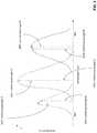
- FIG. 1demonstrates with parallel front and back surfaces of the EPE.
- Incident light 102enters the EPE 100 via the back surface 104 and encounters an input grating 106 .
- Lightpropagates inside the EPE 100 by multiple total internal reflections (TIR) and the color space is controlled by having a stack of EPE plates, for example separate plates for red (R) and green (G) as well as blue (B) primary color bands.
- TIRtotal internal reflections
- Rred
- Ggreen
- Bblue
- Light exiting the EPE 100is expanded by these internal reflections and passes through an output grating 108 and exits normal to the front surface 110 , which is parallel to the opposed back surface 104 . This plate stacking necessarily complicates the design and raises its cost.
- the individual beams in FIG. 1represent different colors (R, G, B) each defining a different wavelength ⁇ .
- an optical channelcomprising an entrance pupil enabling light to enter the optical channel, an exit pupil enabling the light to exit the optical channel, a back surface adjacent to the entrance pupil, and a front surface opposite the back surface.
- the optical channelis configured such that a first distance at the entrance pupil between the front surface and the back surface is different from a second distance at the exit pupil between the front surface and the back surface.
- a head-wearable imaging devicecomprising a micro display and an exit pupil expander.
- the head-wearable imaging devicemay for example be a virtual reality device or an augmented reality device.
- the exit pupil expandercomprises: an entrance pupil configured to in-couple light from the micro-display; an exit pupil configured to out-couple light from the exit pupil expander; a back surface adjacent to the entrance pupil; and a front surface opposite the back surface.
- the exit pupil expanderis geometrically configured such that the light defining a center wavelength that enters the optical channel at the entrance pupil perpendicular to the back surface experiences angularly varying total internal reflection between the front and back surfaces such that the light that exits the optical channel perpendicular to the exit pupil is at a wavelength shifted from the center wavelength.
- the exit pupil expandermay be as described above for the optical channel according to the second aspect of these teachings.
- FIG. 1is a schematic diagram illustrating a prior art exit pupil expander with parallel front and back surfaces according to the prior art.
- FIG. 2is a schematic diagram illustrating a wedge-shaped exit pupil expander with non-parallel front and back surfaces according to an embodiment of these teachings.
- FIG. 5is similar to FIG. 2 but further illustrating a compensating wedge for see-through (non-virtual reality) type applications according to an example embodiment.
- FIG. 7is a schematic diagram of an exit pupil expander that includes a main channel or body with a thin film wedge overlay that imposes the angularly varying total internal reflection according to these teachings.
- FIG. 8is a schematic diagram of a wedge-type exit pupil expander similar to that of FIG. 2 , but along with the inset FIG. 8A which is similar to FIG. 3 these more fully illustrate exit pupil expansion of only a single wavelength/color.
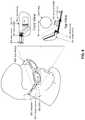
- FIG. 9is a perspective view of a non-virtual reality headset which is one type of device 900 in which embodiments of these teachings may be disposed, with front and top views particularly illustrating one example for placement of an EPE.
- Certain non-limiting embodiments of these teachingsprovide a wedge-shaped EPE (exit pupil expander) plate for controlling color space as generally shown at FIG. 2 .
- the front 210 and opposed back 204 surfaces of the EPE 200are non-parallel.
- These surfaces 204 , 210refer to internal reflective surfaces upon which the light reflects within the optical channel/EPE 200 and are sometimes referred to as plates.
- Light 202propagates inside the EPE 200 through total internal reflection from these surfaces 204 , 210 and experiences a varying degree of angular variation due to non-parallelism of these surfaces/plates 204 , 210 .
- the angular spread of the out-coupled lightis affected and a user sees the angular shift as a color change of the light source as compared to the incident light 202 that was input through the back surface 204 at the input grating 206 . That is, the wedge-shaped EPE 200 shifts the diffracted light from the central emitted wavelength of the light source, which in FIG. 2 is represented as the incident light 202 . Improved color balance is achieved by controlling the wedge-shape of the EPE 200 .
- the light reflecting off these surfaces 204 , 210 propagating inside the wedge-shaped EPE 200 by TIRexperiences a varying degree of angular variation, as a result of the non-parallelism of the surfaces/plates 204 , 210 .
- LEDslight-emitting diodes
- the userwill see the resulting angular shift as a color change of the light source because the diffracted light is shifted from the dominant or from the central-emitted wavelength of the LED.
- the optical channel/EPE 200 of FIG. 2is configured such that a first distance 220 at the entrance pupil/input grating 206 between the front surface 210 and the back surface 204 is different from a second distance 222 at the exit pupil/output grating 208 between the front surface 210 and the back surface 204 .
- the specific location of these distances 220 , 222 in FIG. 2is to avoid obscuring the ray traces through the channel; the appropriate locations would follow one particular ray of a given wavelength from input to output pupil (which are delineated in the drawings as input and output gratings) of the channel/EPE 200 .
- the extent of the wedgeis such that this wavelength ray tracing is not relevant to these distances, where for example a smallest first distance 220 anywhere along the entrance pupil/input grating 206 is larger than a largest second distance 222 anywhere along the exit pupil/output grating 208 .
- FIGS. 1 and 2quantitatively. Assuming for simplicity that the characteristics of the input grating and the output grating are identical, the output coupled light experiences a color shift across the output grating.
- FIG. 2the improved color balance achieved by the wedged plates 204 , 210 is shown. If the wedge angle ⁇ shown at FIG. 2 is chosen appropriately, the color shift across the output grating 208 is offset by the shift in the central wavelength of the respective light sources for R, G, and B. In FIG. 2 the central wavelength is followed with solid lines, and the shifted wavelengths are shown in dashed lines.
- FIG. 3This is also shown in FIG. 3 , where the spectra of the light sources are shown, with solid line indicators for the central (peak) wavelengths for Blue 301 C; Green 302 C and Red 303 C as well as dashed line indicators for the shifted wavelengths for Blue 301 S; Green 302 S and Red 303 S as seen by the user when the EPE is wedge-shaped as shown by the FIG. 2 example embodiment.
- FIG. 4reproduces the calculations for the color shifting plotted at FIG. 3 .
- FIG. 4also shows the angular differences between the diffracted input and output angles. If the value of the angle ⁇ were set to zero the resulting EPE would be as shown at FIG. 1 and the calculations shown at FIG. 4 would return to the original (input) wavelength and the output angles would be equal to the input angles.
- the basic wedge-shaped EPE 200is only one of several EPE designs that will produce a color shift in the out-coupled light according to these teachings. While the FIG. 2 example shows the wedge narrowing between the input 202 (input grating 206 ) and the output (output grating 210 ) a similar color shifting benefit can be achieved with an expanding or widening wedge shape.
- FIG. 5illustrates how a basic wedge-shape such as that shown at FIG. 2 can be adapted for a see-through display such as an eye-glass mounted micro-display that is transparent to visible light from the user's environment.
- a see-through displaysuch as an eye-glass mounted micro-display that is transparent to visible light from the user's environment.
- Like reference numbersdenote similar features as detailed above with respect to FIG. 2 .
- the incident light 202 forming the image to be projected in front of or on the user's eyeis designated 502 A in FIG. 5 to distinguish over the incident environmental light 502 B that the user perceives directly that is not subject to internal reflection off the non-parallel surfaces 204 , 210 within the EPE 200 .
- That incident environmental light 502 Bpasses through a compensating wedge 500 that defines opposed surfaces 510 , 504 such that the surface 510 adjacent to the wedge-shaped EPE 200 is parallel to the back surface 204 of the EPE 200 and the surface opposite the EPE 200 is parallel to the front surface 210 of the EPE 200 .
- the compensating wedgewidens to exactly match across the expanse of the compensating wedge 500 (or at least across the entrance and exit pupils of that compensating wedge 500 ).
- the angle ⁇ shown for the EPE 200is the same angle ⁇ used for the compensating wedge 500 but offset 180 degrees (shown as 180 ⁇ on the compensating wedge 500 ).
- segment-wise wedged EPE 600defines three distinct segments 600 A, 600 B, 600 C through which the incident light 602 propagates.
- Incident light 602 from the computer of the overall optical headset/eyeglass device forming the image to be projectedis in-coupled through the back surface 604 A of the first segment 600 A which defines a narrowing wedge between opposed internal reflective surfaces 604 A and 610 A. From this first segment 600 A the light continues through the second segment 600 B which has parallel opposed internal reflective surfaces 604 B, 610 B.
- the lightcontinues into the third segment 600 C where it is out coupled 612 after reflecting between back 604 C and front 610 C surfaces which also define a narrowing wedge.
- At least input and output gratings similar to those shown at FIG. 2are assumed though not shown at FIG. 6 , and further the second segment 600 B with parallel opposed surfaces 604 B, 610 B may also incorporate diffraction gratings along those surfaces.
- FIG. 7illustrates a further embodiment of an EPE 700 in which there is a thin film wedge 714 overlying the front surface with a thin air gap 718 between the thin film wedge 714 and the main EPE body 712 .
- Optical mediums other than airmay also be used for this thin gap.
- the main EPE body 712has parallel opposed surfaces 704 A, 710 A.
- incident light 702enters through the back surface 704 A at the input grating 706 and is refracted internal of the channel between those surfaces 704 A, 710 A.
- the wedge overlay 714is disposed opposite that input pupil such that the first refraction at the input grating directs the light towards the wedge overlay 714 , which extends along only a portion of the main EPE body 712 .
- the extent of that portiondepends on the characteristics of that first diffraction angle and the wavelength or wavelengths the designer selects for evanescent coupling back into the optical channel of the main EPE body 712 .
- the example at FIG. 7shows blue and red light are incident 702 ; blue at the left and red at the right of the input grating 706 .
- the blue lightreflects into the thin film wedge 714 which extends far enough that a portion of this same blue light is also reflected from its front surface 710 B through its back surface 704 B to re-enter the main EPE body 712 .
- the distal end 716 of the wedge overlay 714prevents similar reflection of the red light that entered the wedge overlay 714 from being reflected back into that main EPE body 712 .
- the ‘leaky’ input lightcan be filtered in and other wavelengths of light can be filtered out by selection of the wedge angle of the wedge overlay 714 and the position of the distal end 716 (for a given input grating 706 ).
- the output grating 708is disposed along the rear surface 704 A to show the advantages of these teachings do not depend on light being out-coupled from the surface opposite where it was in-coupled, and this feature can be incorporated into any of the other examples herein (except for the see-through embodiment of FIG. 5 it would be realized by in-coupling and out-coupling through the front surface 210 to retain the see-through feature).
- Some conventionsprefer to name the surface adjacent to the output grating as the front surface, in which case surface 704 A of FIG.
- the front surface and surface 710 Awould be named the back/rear surface; the terms front and back or rear surfaces as used herein merely designate opposing surfaces and the input/output pupils are specifically illustrated so there is no ambiguity.
- the micro-display which provides the image seen by the useris not particularly shown at FIGS. 1-8 ; the micro-display and optical engine of the host device is the source of the incident light 702 that is in-coupled to the EPE via the input grating and out-coupled from it via the output grating.
- Micro-displays and optical engines to drive themare well known in the head-wearable visual imaging arts; these known micro-displays and optical engines are suitable for providing the image that is in-coupled to the EPE embodiments described herein and need not be further detailed.
- optical devicessuch as retinal scanning displays the image is projected directly on the user's retina and such embodiments may or may not have any output grating at the exit pupil of the EPE.
- FIG. 8illustrates a basic wedge-type EPE 200 similar to that shown at FIG. 2 but illustrating field of view aspects of these teachings; the inset at FIG. 8A is similar in kind to the data plot of FIG. 3 .
- the user's field of viewis illustrated for only one color, blue which is incident 202 across the entire input grating 206 at zero degrees (normal to the plane of the grating).
- the solid arrows out-coupled from the output grating 208represent the directions of the central peak of the color, and this central peak is also delineated at the inset with a solid arrow.
- the dashed arrows out-coupled from the output grating 208show the side of the spectrum color that are coupled towards the user's pupil 850 , where the dashed arrows p 1 , p 2 and p 3 also illustrated at the inset. Note that those dashed arrows are on either side of the color peak even for this basic wedge design.
- the field of viewhas the color error that is imposed by the non-parallel channel of the EPE 200 , so long as this error is not otherwise compensated within the EPE 200 .
- One particular technical effect of embodiments of these teachingsis an improved color space provided by augmented reality and virtual reality viewing devices, and at a reduced cost.
- Such augmented reality or virtual reality deviceswould need to be designed such that the characteristics of the diffraction gratings take into account the wedge angle ⁇ but this would be an engineering matter more than compensated by volume sales of these retail end user devices.
- an optical channelcomprising an entrance pupil enabling light to enter the optical channel; an exit pupil enabling the light to exit the optical channel; a back surface 204 adjacent to the entrance pupil; and a front surface 210 opposite the back surface.
- the entrance pupilis designated by the input grating 206 and the exit pupil is designated by the output grating 208 ; while typical embodiments will have such gratings at those entrance and exit pupils the gratings themselves are not an essential part of the novel aspects of the optical channel/EPE presented herein.
- the optical channel/EPEis geometrically configured, that is its shape is designed, such that the light defining a center wavelength that enters the optical channel at the entrance pupil perpendicular to the back surface experiences angularly varying total internal reflection between the front and back surfaces such that the light that exits the optical channel perpendicular to the exit pupil is at a wavelength shifted from the center wavelength.
- the dashed lines exiting the output grating 208are perpendicular, and FIG. 3 as well as the inset FIG. 8A illustrate the shift of the dashed line wavelengths as compared to the solid-line peak which is the wavelength that entered the channel at the input grating 206 .
- the center wavelength (solid line) of the lightis expanded by the angularly varying total internal reflection such that a) a first portion of the expanded light that exits the optical channel perpendicular to the exit pupil (the dashed lines) is at a wavelength shifted from the center wavelength; and b) a second portion of the expanded light that exits the optical channel non-perpendicular to the exit pupil (the solid lines) is at the center wavelength.
- the solid versus dashed line peaks at both FIGS. 3 and 8Ashow that this second portion of the expanded light that exits the optical channel non-perpendicular to the exit pupil exhibits a greater intensity than the first portion of the expanded light that exits the optical channel perpendicular to the exit pupil.
- the optical channelis geometrically configured such that the front surface and the back surface are non-parallel. While flat non-parallel surfaces are shown curved surfaces can also be employed to take advantage of these teachings.
- the front surface 210is adjacent to the exit pupil and the optical channel 200 is a see-through exit pupil expander further comprising a compensating wedge 500 disposed adjacent to a portion of the back surface 204 opposite the exit pupil, and this compensating wedge is transparent to incident environmental light 502 B and is further geometrically configured to offset angular variance that the optical channel 200 imposes on incident environmental light 502 B that passes into the optical channel via the compensating wedge.
- FIG. 6demonstrated an example of a segmented EPE 600 , and in this case the front and back surfaces define at least first ( 600 B) and second ( 600 A and/or 600 C) discrete geometric segments of the optical channel, wherein the front and back surfaces are parallel in the first discrete geometric segment 600 B and non-parallel in at least the second discrete geometric segment 600 A/ 600 C.
- FIG. 7Another embodiment shown particularly at FIG. 7 had the optical channel/EPE comprising a main channel or body 712 and a wedge overlay 714 .
- the front and back surfaces mentioned abovewould be considered the front 710 A and rear 704 A surfaces of the main channel 712 ;
- the wedge overlaywould define non-parallel front 710 B and back 704 B overlay surfaces;
- the wedge overlaywould be disposed adjacent to the front surface 710 A of the main channel opposite the entrance pupil; and at least some of the angularly varying total internal reflection between the front and back surfaces are between the front surface 710 B of the wedge overlay 714 and the back surface 704 A of the main channel 712 .
- a particularly useful aspect of the wedge overlay conceptis that disposition of a distal end 716 of the wedge overlay 714 relative to the entrance pupil filters incident light 702 passing through the entrance pupil such that only wavelengths above or below a threshold experience the angularly varying total internal reflection while remaining wavelengths experience total internal reflection that is not angularly varying.
- such an optical channel 200comprises an entrance pupil enabling light 202 to enter the optical channel; an exit pupil enabling the light to exit the optical channel; a back surface 204 adjacent to the entrance pupil; and a front surface 210 opposite the back surface.
- the drawingsdepict the entrance pupil as the input grating 206 and the exit pupil as the output grating 208 , and such gratings may be common to most implementations but are not essential, particularly the output grating is not needed if the host device is of the retinal scanning variety.
- the optical channelis configured such that a first distance 220 at the entrance pupil between the front surface 210 and the back surface 204 is different from a second distance 222 at the exit pupil between the front surface 210 and the back surface 204 .
- the front and back surfaces of the optical channelare configured to form a continuous wedge defining an angle ⁇ that quantifies an amount of non-parallelism between them.
- Those particularly illustrated embodimentshave the first distance greater than the second distance, but an opposite arrangement is also possible within these teachings.
- FIG. 5 embodimentis shown as a continuous wedge this is a non-limiting feature of the see-through/non-virtual reality embodiment of the exit pupil expander where the front surface 210 is adjacent to the exit pupil.
- the see-through exit pupil expanderfurther comprises a compensating wedge 500 disposed adjacent to a portion of the back surface 204 opposite the exit pupil, and as detailed above this compensating wedge is transparent to incident environmental light 502 B and geometrically configured to offset exit pupil expansion that the optical channel/EPE 200 imposes on incident environmental light 502 B that passes into the optical channel/EPE via the compensating wedge 500 .
- the FIG. 6 embodimenthas the front and back surfaces defining at least first and second discrete geometric segments of the optical channel, wherein the front and back surfaces are parallel in the first discrete geometric segment and non-parallel in at least the second discrete geometric segment as detailed above in the functional description of the FIG. 6 embodiment.
- optical channelcomprising a main channel 712 and a wedge overlay 714 , and this also is fully described above in the functional description of this embodiment.
- Embodiments of these teachingsinclude the overall host device in which such an optical channel/EPE may be deployed.
- a host deviceis shown by example at FIG. 9 as a head-wearable imaging device which comprises a micro display that would be disposed at the image source 904 and an exit pupil expander disposed between the source 904 and the eyepiece as shown.
- the exit pupil expandermay be as detailed more particularly above with entrance and exit pupils to respectively in-couple and out-couple light from the micro-display and front and back surfaces to angularly vary the total internal reflection of the light passing between those pupils.
- the head-wearable imaging deviceis a virtual reality imaging device that isolates the user's field of view from the surrounding environment.
- the head-wearable imaging deviceis an augmented reality device such as the particular example shown at FIG. 9 , in which case there may further be a compensating wedge along the lines of the example at FIG. 5 and disposed opposite the exit pupil such that incident environmental light 502 B passes into the exit pupil expander 200 through the compensating wedge 500 and passes out of the exit pupil expander through the exit pupil without total internal reflection.
- FIG. 9is a perspective view of a non-virtual reality headset which is one type of device 900 in which embodiments of these teachings may be disposed.
- the EPE 200would be disposed to lie along the user's temple when the device is worn, either within the earpiece 902 or separately but substantially alongside the earpiece as FIG. 9 specifically shows.
- the EPE 200may be disposed along the user's temple as FIG. 9 illustrates, or it may be disposed to run laterally along the user's face from the temple to the eye center.
- the image source 904may generate the image itself, in others it may include a wireless receiver that receives the digitized image over a Bluetooth or other wireless connection and simply renders the received image for visual presentation.
Landscapes
- Physics & Mathematics (AREA)
- General Physics & Mathematics (AREA)
- Optics & Photonics (AREA)
Abstract
Description
Claims (16)
Priority Applications (4)
| Application Number | Priority Date | Filing Date | Title |
|---|---|---|---|
| US15/659,732US10578870B2 (en) | 2017-07-26 | 2017-07-26 | Exit pupil expander |
| US16/748,193US11567324B2 (en) | 2017-07-26 | 2020-01-21 | Exit pupil expander |
| US18/145,416US11927759B2 (en) | 2017-07-26 | 2022-12-22 | Exit pupil expander |
| US18/432,547US20240176148A1 (en) | 2017-07-26 | 2024-02-05 | Exit pupil expander |
Applications Claiming Priority (1)
| Application Number | Priority Date | Filing Date | Title |
|---|---|---|---|
| US15/659,732US10578870B2 (en) | 2017-07-26 | 2017-07-26 | Exit pupil expander |
Related Child Applications (1)
| Application Number | Title | Priority Date | Filing Date |
|---|---|---|---|
| US16/748,193ContinuationUS11567324B2 (en) | 2017-07-26 | 2020-01-21 | Exit pupil expander |
Publications (2)
| Publication Number | Publication Date |
|---|---|
| US20190033592A1 US20190033592A1 (en) | 2019-01-31 |
| US10578870B2true US10578870B2 (en) | 2020-03-03 |
Family
ID=65138240
Family Applications (4)
| Application Number | Title | Priority Date | Filing Date |
|---|---|---|---|
| US15/659,732Active2038-01-10US10578870B2 (en) | 2017-07-26 | 2017-07-26 | Exit pupil expander |
| US16/748,193Active2037-11-21US11567324B2 (en) | 2017-07-26 | 2020-01-21 | Exit pupil expander |
| US18/145,416ActiveUS11927759B2 (en) | 2017-07-26 | 2022-12-22 | Exit pupil expander |
| US18/432,547PendingUS20240176148A1 (en) | 2017-07-26 | 2024-02-05 | Exit pupil expander |
Family Applications After (3)
| Application Number | Title | Priority Date | Filing Date |
|---|---|---|---|
| US16/748,193Active2037-11-21US11567324B2 (en) | 2017-07-26 | 2020-01-21 | Exit pupil expander |
| US18/145,416ActiveUS11927759B2 (en) | 2017-07-26 | 2022-12-22 | Exit pupil expander |
| US18/432,547PendingUS20240176148A1 (en) | 2017-07-26 | 2024-02-05 | Exit pupil expander |
Country Status (1)
| Country | Link |
|---|---|
| US (4) | US10578870B2 (en) |
Cited By (29)
| Publication number | Priority date | Publication date | Assignee | Title |
|---|---|---|---|---|
| US11189252B2 (en) | 2018-03-15 | 2021-11-30 | Magic Leap, Inc. | Image correction due to deformation of components of a viewing device |
| US11187923B2 (en) | 2017-12-20 | 2021-11-30 | Magic Leap, Inc. | Insert for augmented reality viewing device |
| US11200870B2 (en) | 2018-06-05 | 2021-12-14 | Magic Leap, Inc. | Homography transformation matrices based temperature calibration of a viewing system |
| US11199713B2 (en) | 2016-12-30 | 2021-12-14 | Magic Leap, Inc. | Polychromatic light out-coupling apparatus, near-eye displays comprising the same, and method of out-coupling polychromatic light |
| US11204491B2 (en) | 2018-05-30 | 2021-12-21 | Magic Leap, Inc. | Compact variable focus configurations |
| US11210808B2 (en) | 2016-12-29 | 2021-12-28 | Magic Leap, Inc. | Systems and methods for augmented reality |
| US11216086B2 (en) | 2018-08-03 | 2022-01-04 | Magic Leap, Inc. | Unfused pose-based drift correction of a fused pose of a totem in a user interaction system |
| US11280937B2 (en) | 2017-12-10 | 2022-03-22 | Magic Leap, Inc. | Anti-reflective coatings on optical waveguides |
| US11347960B2 (en) | 2015-02-26 | 2022-05-31 | Magic Leap, Inc. | Apparatus for a near-eye display |
| US11425189B2 (en) | 2019-02-06 | 2022-08-23 | Magic Leap, Inc. | Target intent-based clock speed determination and adjustment to limit total heat generated by multiple processors |
| US11445232B2 (en) | 2019-05-01 | 2022-09-13 | Magic Leap, Inc. | Content provisioning system and method |
| US11510027B2 (en) | 2018-07-03 | 2022-11-22 | Magic Leap, Inc. | Systems and methods for virtual and augmented reality |
| US11514673B2 (en) | 2019-07-26 | 2022-11-29 | Magic Leap, Inc. | Systems and methods for augmented reality |
| US11521296B2 (en) | 2018-11-16 | 2022-12-06 | Magic Leap, Inc. | Image size triggered clarification to maintain image sharpness |
| US11567324B2 (en)* | 2017-07-26 | 2023-01-31 | Magic Leap, Inc. | Exit pupil expander |
| US11579441B2 (en) | 2018-07-02 | 2023-02-14 | Magic Leap, Inc. | Pixel intensity modulation using modifying gain values |
| US11598651B2 (en) | 2018-07-24 | 2023-03-07 | Magic Leap, Inc. | Temperature dependent calibration of movement detection devices |
| US11624929B2 (en) | 2018-07-24 | 2023-04-11 | Magic Leap, Inc. | Viewing device with dust seal integration |
| US11630507B2 (en) | 2018-08-02 | 2023-04-18 | Magic Leap, Inc. | Viewing system with interpupillary distance compensation based on head motion |
| US11737832B2 (en) | 2019-11-15 | 2023-08-29 | Magic Leap, Inc. | Viewing system for use in a surgical environment |
| US11740466B1 (en) | 2020-03-20 | 2023-08-29 | Apple Inc. | Optical systems with scanning mirror input couplers |
| US11762623B2 (en) | 2019-03-12 | 2023-09-19 | Magic Leap, Inc. | Registration of local content between first and second augmented reality viewers |
| US11856479B2 (en) | 2018-07-03 | 2023-12-26 | Magic Leap, Inc. | Systems and methods for virtual and augmented reality along a route with markers |
| US11885871B2 (en) | 2018-05-31 | 2024-01-30 | Magic Leap, Inc. | Radar head pose localization |
| US12016719B2 (en) | 2018-08-22 | 2024-06-25 | Magic Leap, Inc. | Patient viewing system |
| US12033081B2 (en) | 2019-11-14 | 2024-07-09 | Magic Leap, Inc. | Systems and methods for virtual and augmented reality |
| US12044851B2 (en) | 2018-12-21 | 2024-07-23 | Magic Leap, Inc. | Air pocket structures for promoting total internal reflection in a waveguide |
| US12164978B2 (en) | 2018-07-10 | 2024-12-10 | Magic Leap, Inc. | Thread weave for cross-instruction set architecture procedure calls |
| US12442967B2 (en) | 2021-09-22 | 2025-10-14 | Apple Inc. | Optical systems having gradient index optical structures |
Families Citing this family (4)
| Publication number | Priority date | Publication date | Assignee | Title |
|---|---|---|---|---|
| US12148105B2 (en)* | 2022-03-30 | 2024-11-19 | Snap Inc. | Surface normals for pixel-aligned object |
| US12254577B2 (en) | 2022-04-05 | 2025-03-18 | Snap Inc. | Pixel depth determination for object |
| GB2618554B (en)* | 2022-05-10 | 2024-10-02 | Envisics Ltd | Compact head-up display and waveguide therefor |
| US12429953B2 (en) | 2022-12-09 | 2025-09-30 | Snap Inc. | Multi-SoC hand-tracking platform |
Citations (11)
| Publication number | Priority date | Publication date | Assignee | Title |
|---|---|---|---|---|
| US20100079841A1 (en)* | 2008-09-26 | 2010-04-01 | Nokia Corporation | Device and a method for polarized illumination of a micro-display |
| US7719767B2 (en) | 2008-06-27 | 2010-05-18 | Industrial Technology Research Institute | Composite light division device and image apparatus using the same |
| US20110216266A1 (en) | 2010-03-02 | 2011-09-08 | Microsoft Corporation | Wedge backlight with diffraction grating |
| US8064138B2 (en) | 2003-10-09 | 2011-11-22 | International Business Machines Corporation | Dispersive element, diffraction grating, color display device, demultiplexer, and diffraction grating manufacture |
| US8400537B2 (en) | 2008-11-13 | 2013-03-19 | Omnivision Technologies, Inc. | Image sensors having gratings for color separation |
| US8508848B2 (en) | 2007-12-18 | 2013-08-13 | Nokia Corporation | Exit pupil expanders with wide field-of-view |
| CN103513422A (en) | 2013-09-27 | 2014-01-15 | 上海理工大学 | Perspective display device |
| US20140140654A1 (en) | 2012-11-16 | 2014-05-22 | Sbg Labs, Inc. | Transparent waveguide display |
| US20170115487A1 (en)* | 2015-10-23 | 2017-04-27 | Microsoft Technology Licensing, Llc | Holographic display |
| US20170192239A1 (en)* | 2016-01-06 | 2017-07-06 | Naoki Nakamura | Light guide, virtual image display device, and light guide unit |
| US20170329137A1 (en)* | 2016-05-16 | 2017-11-16 | Jani Kari Tapio Tervo | Wedges for light transformation |
Family Cites Families (496)
| Publication number | Priority date | Publication date | Assignee | Title |
|---|---|---|---|---|
| US6541736B1 (en) | 2001-12-10 | 2003-04-01 | Usun Technology Co., Ltd. | Circuit board/printed circuit board having pre-reserved conductive heating circuits |
| US4344092A (en) | 1980-10-21 | 1982-08-10 | Circon Corporation | Miniature video camera means for video system |
| US4652930A (en) | 1984-11-19 | 1987-03-24 | Rca Corporation | Television camera structure |
| US4810080A (en) | 1987-09-03 | 1989-03-07 | American Optical Corporation | Protective eyewear with removable nosepiece and corrective spectacle |
| US5142684A (en) | 1989-06-23 | 1992-08-25 | Hand Held Products, Inc. | Power conservation in microprocessor controlled devices |
| US4997268A (en) | 1989-07-24 | 1991-03-05 | Dauvergne Hector A | Corrective lens configuration |
| US5074295A (en) | 1989-08-03 | 1991-12-24 | Jamie, Inc. | Mouth-held holder |
| JPH0712944Y2 (en) | 1989-08-24 | 1995-03-29 | 株式会社アドバンテスト | Electronic component mounting board temperature protection structure |
| US5007727A (en) | 1990-02-26 | 1991-04-16 | Alan Kahaney | Combination prescription lens and sunglasses assembly |
| US5396635A (en) | 1990-06-01 | 1995-03-07 | Vadem Corporation | Power conservation apparatus having multiple power reduction levels dependent upon the activity of the computer system |
| US5240220A (en) | 1990-09-12 | 1993-08-31 | Elbex Video Ltd. | TV camera supporting device |
| DE69225826T2 (en) | 1991-03-22 | 1998-10-15 | Nippon Kogaku Kk | Optical apparatus for correcting the image shift |
| WO1993001743A1 (en) | 1991-07-22 | 1993-02-04 | Adair Edwin Lloyd | Sterile video microscope holder for operating room |
| US5251635A (en) | 1991-09-03 | 1993-10-12 | General Electric Company | Stereoscopic X-ray fluoroscopy system using radiofrequency fields |
| US5224198A (en) | 1991-09-30 | 1993-06-29 | Motorola, Inc. | Waveguide virtual image display |
| CA2061117C (en) | 1991-12-02 | 1998-09-29 | Neta J. Amit | Apparatus and method for distributed program stack |
| US5497463A (en) | 1992-09-25 | 1996-03-05 | Bull Hn Information Systems Inc. | Ally mechanism for interconnecting non-distributed computing environment (DCE) and DCE systems to operate in a network system |
| US5937202A (en) | 1993-02-11 | 1999-08-10 | 3-D Computing, Inc. | High-speed, parallel, processor architecture for front-end electronics, based on a single type of ASIC, and method use thereof |
| US5410763A (en) | 1993-02-11 | 1995-05-02 | Etablissments Bolle | Eyeshield with detachable components |
| US5682255A (en) | 1993-02-26 | 1997-10-28 | Yeda Research & Development Co. Ltd. | Holographic optical devices for the transmission of optical signals of a plurality of channels |
| US6023288A (en) | 1993-03-31 | 2000-02-08 | Cairns & Brother Inc. | Combination head-protective helmet and thermal imaging apparatus |
| EP0632360A1 (en) | 1993-06-29 | 1995-01-04 | Xerox Corporation | Reducing computer power consumption by dynamic voltage and frequency variation |
| US5455625A (en) | 1993-09-23 | 1995-10-03 | Rosco Inc. | Video camera unit, protective enclosure and power circuit for same, particularly for use in vehicles |
| US5835061A (en) | 1995-06-06 | 1998-11-10 | Wayport, Inc. | Method and apparatus for geographic-based communications service |
| US5826092A (en) | 1995-09-15 | 1998-10-20 | Gateway 2000, Inc. | Method and apparatus for performance optimization in power-managed computer systems |
| US5864365A (en) | 1996-01-26 | 1999-01-26 | Kaman Sciences Corporation | Environmentally controlled camera housing assembly |
| US6064749A (en) | 1996-08-02 | 2000-05-16 | Hirota; Gentaro | Hybrid tracking for augmented reality using both camera motion detection and landmark tracking |
| US5854872A (en) | 1996-10-08 | 1998-12-29 | Clio Technologies, Inc. | Divergent angle rotator system and method for collimating light beams |
| US8005254B2 (en) | 1996-11-12 | 2011-08-23 | Digimarc Corporation | Background watermark processing |
| US6012811A (en) | 1996-12-13 | 2000-01-11 | Contour Optik, Inc. | Eyeglass frames with magnets at bridges for attachment |
| JP3651204B2 (en) | 1996-12-18 | 2005-05-25 | トヨタ自動車株式会社 | Stereoscopic image display device, stereoscopic image display method, and recording medium |
| JP3465528B2 (en) | 1997-04-22 | 2003-11-10 | 三菱瓦斯化学株式会社 | New resin for optical materials |
| ES2280096T3 (en) | 1997-08-29 | 2007-09-01 | Kabushiki Kaisha Sega Doing Business As Sega Corporation | IMAGE PROCESSING SYSTEM AND IMAGE PROCESSING METHOD. |
| JPH11142783A (en) | 1997-11-12 | 1999-05-28 | Olympus Optical Co Ltd | Image display device |
| US6385735B1 (en) | 1997-12-15 | 2002-05-07 | Intel Corporation | Method and apparatus for limiting processor clock frequency |
| US6191809B1 (en) | 1998-01-15 | 2001-02-20 | Vista Medical Technologies, Inc. | Method and apparatus for aligning stereo images |
| US6076927A (en) | 1998-07-10 | 2000-06-20 | Owens; Raymond L. | Adjustable focal length eye glasses |
| JP2000099332A (en) | 1998-09-25 | 2000-04-07 | Hitachi Ltd | Remote procedure call optimization method and program execution method using the same |
| US6415388B1 (en) | 1998-10-30 | 2002-07-02 | Intel Corporation | Method and apparatus for power throttling in a microprocessor using a closed loop feedback system |
| US6918667B1 (en) | 1998-11-02 | 2005-07-19 | Gary Martin Zelman | Auxiliary eyewear attachment apparatus |
| US6487319B1 (en) | 1998-11-18 | 2002-11-26 | Sarnoff Corporation | Apparatus and method for identifying the location of a coding unit |
| US7111290B1 (en) | 1999-01-28 | 2006-09-19 | Ati International Srl | Profiling program execution to identify frequently-executed portions and to assist binary translation |
| US6556245B1 (en) | 1999-03-08 | 2003-04-29 | Larry Allan Holmberg | Game hunting video camera |
| US7119819B1 (en) | 1999-04-06 | 2006-10-10 | Microsoft Corporation | Method and apparatus for supporting two-dimensional windows in a three-dimensional environment |
| US6375369B1 (en) | 1999-04-22 | 2002-04-23 | Videolarm, Inc. | Housing for a surveillance camera |
| AU2001233019A1 (en) | 2000-01-28 | 2001-08-07 | Intersense, Inc. | Self-referenced tracking |
| JP4921634B2 (en) | 2000-01-31 | 2012-04-25 | グーグル インコーポレイテッド | Display device |
| KR100487543B1 (en) | 2000-09-01 | 2005-05-03 | 엘지전자 주식회사 | Cpu scheduling method |
| JP4646374B2 (en) | 2000-09-29 | 2011-03-09 | オリンパス株式会社 | Image observation optical system |
| TW522256B (en) | 2000-12-15 | 2003-03-01 | Samsung Electronics Co Ltd | Wearable display system |
| US6715089B2 (en) | 2001-01-22 | 2004-03-30 | Ati International Srl | Reducing power consumption by estimating engine load and reducing engine clock speed |
| US20020108064A1 (en) | 2001-02-07 | 2002-08-08 | Patrick Nunally | System and method for optimizing power/performance in network-centric microprocessor-controlled devices |
| US6807352B2 (en) | 2001-02-11 | 2004-10-19 | Georgia Tech Research Corporation | Optical waveguides with embedded air-gap cladding layer and methods of fabrication thereof |
| US6931596B2 (en) | 2001-03-05 | 2005-08-16 | Koninklijke Philips Electronics N.V. | Automatic positioning of display depending upon the viewer's location |
| US20020140848A1 (en) | 2001-03-30 | 2002-10-03 | Pelco | Controllable sealed chamber for surveillance camera |
| EP1249717A3 (en) | 2001-04-10 | 2005-05-11 | Matsushita Electric Industrial Co., Ltd. | Antireflection coating and optical element using the same |
| JPWO2002088913A1 (en) | 2001-04-27 | 2004-08-19 | インターナショナル・ビジネス・マシーンズ・コーポレーションInternational Business Maschines Corporation | Method and apparatus for controlling the operating speed of a processor |
| JP4682470B2 (en) | 2001-07-16 | 2011-05-11 | 株式会社デンソー | Scan type display device |
| US6622253B2 (en) | 2001-08-02 | 2003-09-16 | Scientific-Atlanta, Inc. | Controlling processor clock rate based on thread priority |
| US6762845B2 (en) | 2001-08-23 | 2004-07-13 | Zygo Corporation | Multiple-pass interferometry |
| US7101048B2 (en) | 2001-09-25 | 2006-09-05 | Cambridge Flat Protection Displays Limited | Flat-panel projection display |
| US6833955B2 (en) | 2001-10-09 | 2004-12-21 | Planop Planar Optics Ltd. | Compact two-plane optical device |
| AU2002361572A1 (en) | 2001-10-19 | 2003-04-28 | University Of North Carolina At Chape Hill | Methods and systems for dynamic virtual convergence and head mountable display |
| JP3834615B2 (en) | 2001-11-02 | 2006-10-18 | 独立行政法人産業技術総合研究所 | Image display method and system |
| US7076674B2 (en) | 2001-12-19 | 2006-07-11 | Hewlett-Packard Development Company L.P. | Portable computer having dual clock mode |
| JP2003329873A (en) | 2001-12-27 | 2003-11-19 | Fujikura Ltd | Optical fiber gripper with positioning mechanism, optical fiber adapter, and optical fiber processing device |
| US6592220B1 (en) | 2002-01-30 | 2003-07-15 | Lak Cheong | Eyeglass frame with removably mounted lenses |
| US7305020B2 (en) | 2002-02-04 | 2007-12-04 | Vizionware, Inc. | Method and system of reducing electromagnetic interference emissions |
| US6999087B2 (en) | 2002-03-12 | 2006-02-14 | Sun Microsystems, Inc. | Dynamically adjusting sample density in a graphics system |
| EP1351117A1 (en) | 2002-04-03 | 2003-10-08 | Hewlett-Packard Company | Data processing system and method |
| AU2003223746A1 (en) | 2002-04-25 | 2003-11-10 | Arc International | Apparatus and method for managing integrated circuit designs |
| US6849558B2 (en) | 2002-05-22 | 2005-02-01 | The Board Of Trustees Of The Leland Stanford Junior University | Replication and transfer of microstructures and nanostructures |
| KR100382232B1 (en) | 2002-05-31 | 2003-05-09 | Palm Palm Tech | Mobile terminal having enhanced power managing function and power managing method thereof |
| US7046515B1 (en) | 2002-06-06 | 2006-05-16 | Raytheon Company | Method and apparatus for cooling a circuit component |
| US7155617B2 (en) | 2002-08-01 | 2006-12-26 | Texas Instruments Incorporated | Methods and systems for performing dynamic power management via frequency and voltage scaling |
| US6714157B2 (en) | 2002-08-02 | 2004-03-30 | The Boeing Company | Multiple time-interleaved radar operation using a single radar at different angles |
| KR100480786B1 (en) | 2002-09-02 | 2005-04-07 | 삼성전자주식회사 | Integrated type optical head with coupler |
| US20040111248A1 (en) | 2002-09-04 | 2004-06-10 | Granny Nicola V. | Polymorphic computational system and method |
| US7500126B2 (en) | 2002-12-04 | 2009-03-03 | Nxp B.V. | Arrangement and method for controlling power modes of hardware resources |
| US7306337B2 (en) | 2003-03-06 | 2007-12-11 | Rensselaer Polytechnic Institute | Calibration-free gaze tracking under natural head movement |
| DE10311972A1 (en) | 2003-03-18 | 2004-09-30 | Carl Zeiss | Head-mounted display (HMD) apparatus for use with eyeglasses, has optical projector that is fastened to rack, and under which eyeglasses are positioned when rack and eyeglasses are attached together |
| AU2003901272A0 (en) | 2003-03-19 | 2003-04-03 | Martin Hogan Pty Ltd | Improvements in or relating to eyewear attachments |
| US7294360B2 (en) | 2003-03-31 | 2007-11-13 | Planar Systems, Inc. | Conformal coatings for micro-optical elements, and method for making the same |
| US20040205757A1 (en) | 2003-04-09 | 2004-10-14 | Pering Trevor A. | Performance scheduling using multiple constraints |
| CN100416340C (en) | 2003-04-25 | 2008-09-03 | 微型光学公司 | binocular viewing system |
| US20060132914A1 (en) | 2003-06-10 | 2006-06-22 | Victor Weiss | Method and system for displaying an informative image against a background image |
| US20040268159A1 (en) | 2003-06-30 | 2004-12-30 | Microsoft Corporation | Power profiling |
| US7134031B2 (en) | 2003-08-04 | 2006-11-07 | Arm Limited | Performance control within a multi-processor system |
| US7434083B1 (en) | 2004-01-06 | 2008-10-07 | Apple Inc. | Method and apparatus for the generation and control of clock signals |
| JP4699699B2 (en) | 2004-01-15 | 2011-06-15 | 株式会社東芝 | Beam light scanning apparatus and image forming apparatus |
| US7269590B2 (en) | 2004-01-29 | 2007-09-11 | Yahoo! Inc. | Method and system for customizing views of information associated with a social network user |
| US7418170B2 (en) | 2004-03-29 | 2008-08-26 | Sony Corporation | Optical device and virtual image display device |
| JP4364047B2 (en) | 2004-04-14 | 2009-11-11 | オリンパス株式会社 | Display device, imaging device |
| CN100350792C (en) | 2004-04-14 | 2007-11-21 | 奥林巴斯株式会社 | Image capturing apparatus |
| US7219245B1 (en) | 2004-06-03 | 2007-05-15 | Advanced Micro Devices, Inc. | Adaptive CPU clock management |
| US20060019723A1 (en) | 2004-06-29 | 2006-01-26 | Pieter Vorenkamp | Automatic control of power save operation in a portable communication device utilizing historical usage information |
| GB0416038D0 (en) | 2004-07-16 | 2004-08-18 | Portland Press Ltd | Document display system |
| WO2006007868A1 (en) | 2004-07-22 | 2006-01-26 | Pirelli & C. S.P.A. | Integrated wavelength selective grating-based filter |
| WO2006020846A2 (en) | 2004-08-11 | 2006-02-23 | THE GOVERNMENT OF THE UNITED STATES OF AMERICA as represented by THE SECRETARY OF THE NAVY Naval Research Laboratory | Simulated locomotion method and apparatus |
| US8109635B2 (en) | 2004-08-12 | 2012-02-07 | Ophthalmic Imaging Systems | Integrated retinal imager and method |
| US9030532B2 (en) | 2004-08-19 | 2015-05-12 | Microsoft Technology Licensing, Llc | Stereoscopic image display |
| US7029114B2 (en) | 2004-09-03 | 2006-04-18 | E'lite Optik U.S. L.P. | Eyewear assembly with auxiliary frame and lens assembly |
| KR101294551B1 (en) | 2004-09-16 | 2013-08-07 | 가부시키가이샤 니콘 | MgF2 OPTICAL THIN FILM CONTAINING AMORPHOUS SILICON OXIDE BINDER, OPTICAL DEVICE HAVING SAME, AND METHOD FOR PRODUCING SUCH MgF2 OPTICAL THIN FILM |
| US20060090092A1 (en) | 2004-10-25 | 2006-04-27 | Verhulst Anton H | Clock timing adjustment |
| US7536567B2 (en) | 2004-12-10 | 2009-05-19 | Hewlett-Packard Development Company, L.P. | BIOS-based systems and methods of processor power management |
| US20060126181A1 (en) | 2004-12-13 | 2006-06-15 | Nokia Corporation | Method and system for beam expansion in a display device |
| US8619365B2 (en) | 2004-12-29 | 2013-12-31 | Corning Incorporated | Anti-reflective coating for optical windows and elements |
| GB0502453D0 (en) | 2005-02-05 | 2005-03-16 | Cambridge Flat Projection | Flat panel lens |
| US7573640B2 (en) | 2005-04-04 | 2009-08-11 | Mirage Innovations Ltd. | Multi-plane optical apparatus |
| US20060250322A1 (en) | 2005-05-09 | 2006-11-09 | Optics 1, Inc. | Dynamic vergence and focus control for head-mounted displays |
| US7948683B2 (en) | 2006-05-14 | 2011-05-24 | Holochip Corporation | Fluidic lens with manually-adjustable focus |
| US7644148B2 (en) | 2005-05-16 | 2010-01-05 | Hewlett-Packard Development Company, L.P. | Historical data based workload allocation |
| US20090303599A1 (en) | 2005-06-03 | 2009-12-10 | Nokia Corporation | General diffractive optics method for expanding an exit pupil |
| US7364306B2 (en) | 2005-06-20 | 2008-04-29 | Digital Display Innovations, Llc | Field sequential light source modulation for a digital display system |
| JP4776285B2 (en) | 2005-07-01 | 2011-09-21 | ソニー株式会社 | Illumination optical device and virtual image display device using the same |
| JP4660787B2 (en) | 2005-08-25 | 2011-03-30 | 隆広 西岡 | glasses |
| US7739524B2 (en) | 2005-08-29 | 2010-06-15 | The Invention Science Fund I, Inc | Power consumption management |
| US20080043334A1 (en) | 2006-08-18 | 2008-02-21 | Mirage Innovations Ltd. | Diffractive optical relay and method for manufacturing the same |
| US20070058248A1 (en) | 2005-09-14 | 2007-03-15 | Nguyen Minh T | Sport view binocular-zoom lens focus system |
| US7869128B2 (en) | 2005-09-27 | 2011-01-11 | Konica Minolta Holdings, Inc. | Head mounted display |
| US20100232016A1 (en) | 2005-09-28 | 2010-09-16 | Mirage Innovations Ltd. | Stereoscopic Binocular System, Device and Method |
| US7835785B2 (en) | 2005-10-04 | 2010-11-16 | Ascension Technology Corporation | DC magnetic-based position and orientation monitoring system for tracking medical instruments |
| US11428937B2 (en) | 2005-10-07 | 2022-08-30 | Percept Technologies | Enhanced optical and perceptual digital eyewear |
| US8696113B2 (en) | 2005-10-07 | 2014-04-15 | Percept Technologies Inc. | Enhanced optical and perceptual digital eyewear |
| US20070081123A1 (en) | 2005-10-07 | 2007-04-12 | Lewis Scott W | Digital eyewear |
| US9658473B2 (en) | 2005-10-07 | 2017-05-23 | Percept Technologies Inc | Enhanced optical and perceptual digital eyewear |
| KR101193331B1 (en) | 2005-10-14 | 2012-10-19 | 엘지전자 주식회사 | Power Consumption Management System and Method in the Graphic Apparatus |
| EP1943556B1 (en) | 2005-11-03 | 2009-02-11 | Mirage Innovations Ltd. | Binocular optical relay device |
| EP1949147B1 (en) | 2005-11-18 | 2012-03-21 | Nanocomp Oy Ltd. | Method of producing a diffraction grating element |
| EP1952189B1 (en) | 2005-11-21 | 2016-06-01 | Microvision, Inc. | Display with image-guiding substrate |
| US7917573B2 (en) | 2005-11-30 | 2011-03-29 | International Business Machines Corporation | Measuring and reporting processor capacity and processor usage in a computer system with processors of different speed and/or architecture |
| JP2007199841A (en) | 2006-01-24 | 2007-08-09 | Seiko Epson Corp | Electronic device controller, bus control device |
| WO2007085682A1 (en) | 2006-01-26 | 2007-08-02 | Nokia Corporation | Eye tracker device |
| JP2007219106A (en) | 2006-02-16 | 2007-08-30 | Konica Minolta Holdings Inc | Optical device for expanding diameter of luminous flux, video display device and head mount display |
| US7461535B2 (en) | 2006-03-01 | 2008-12-09 | Memsic, Inc. | Multi-temperature programming for accelerometer |
| IL174170A (en) | 2006-03-08 | 2015-02-26 | Abraham Aharoni | Device and method for binocular alignment |
| US7353134B2 (en) | 2006-03-09 | 2008-04-01 | Dean A. Cirielli | Three-dimensional position and motion telemetry input |
| JP5129229B2 (en) | 2006-03-15 | 2013-01-30 | グーグル・インコーポレーテッド | Automatic display of resized images |
| JP2007273733A (en) | 2006-03-31 | 2007-10-18 | Tdk Corp | Manufacturing method of solid state electrolytic capacitor |
| CN101460882B (en) | 2006-06-02 | 2010-10-27 | 诺基亚公司 | Apparatus and method for providing color separation in exit pupil expander and electronic device |
| US7692855B2 (en) | 2006-06-28 | 2010-04-06 | Essilor International Compagnie Generale D'optique | Optical article having a temperature-resistant anti-reflection coating with optimized thickness ratio of low index and high index layers |
| US9015501B2 (en) | 2006-07-13 | 2015-04-21 | International Business Machines Corporation | Structure for asymmetrical performance multi-processors |
| US7724980B1 (en) | 2006-07-24 | 2010-05-25 | Adobe Systems Incorporated | System and method for selective sharpening of images |
| US8214660B2 (en) | 2006-07-26 | 2012-07-03 | International Business Machines Corporation | Structure for an apparatus for monitoring and controlling heat generation in a multi-core processor |
| US7640449B2 (en) | 2006-08-17 | 2009-12-29 | Via Technologies, Inc. | Systems and methods for dynamic clock frequencies for low power design |
| US9582060B2 (en) | 2006-08-31 | 2017-02-28 | Advanced Silicon Technologies Llc | Battery-powered device with reduced power consumption based on an application profile data |
| US20080068557A1 (en) | 2006-09-20 | 2008-03-20 | Gilbert Menduni | Lens holding frame |
| WO2008038058A1 (en) | 2006-09-28 | 2008-04-03 | Nokia Corporation | Beam expansion with three-dimensional diffractive elements |
| RU2009119058A (en) | 2006-10-31 | 2010-12-10 | Ой Модинес Лтд. (Fi) | OUTPUT LIGHT STRUCTURE FOR LIGHT DEVICE |
| US20080146942A1 (en) | 2006-12-13 | 2008-06-19 | Ep Medsystems, Inc. | Catheter Position Tracking Methods Using Fluoroscopy and Rotational Sensors |
| WO2008071830A1 (en) | 2006-12-14 | 2008-06-19 | Nokia Corporation | Display device having two operating modes |
| JP4847351B2 (en) | 2007-01-11 | 2011-12-28 | キヤノン株式会社 | Diffractive optical element and diffraction grating using the same |
| US7418368B2 (en) | 2007-01-18 | 2008-08-26 | International Business Machines Corporation | Method and system for testing processor cores |
| JP4348441B2 (en) | 2007-01-22 | 2009-10-21 | 国立大学法人 大阪教育大学 | Position detection apparatus, position detection method, data determination apparatus, data determination method, computer program, and storage medium |
| US8726681B2 (en) | 2007-01-23 | 2014-05-20 | Hewlett-Packard Development Company, L.P. | Method and system of cooling components of a computer system |
| US8374673B2 (en) | 2007-01-25 | 2013-02-12 | Warsaw Orthopedic, Inc. | Integrated surgical navigational and neuromonitoring system having automated surgical assistance and control |
| US20090017910A1 (en) | 2007-06-22 | 2009-01-15 | Broadcom Corporation | Position and motion tracking of an object |
| JP5194530B2 (en) | 2007-04-09 | 2013-05-08 | 凸版印刷株式会社 | Image display device and image display method |
| US7733439B2 (en) | 2007-04-30 | 2010-06-08 | Qualcomm Mems Technologies, Inc. | Dual film light guide for illuminating displays |
| EP3667399A1 (en) | 2007-06-04 | 2020-06-17 | Magic Leap, Inc. | A diffractive beam expander |
| US8060759B1 (en) | 2007-06-29 | 2011-11-15 | Emc Corporation | System and method of managing and optimizing power consumption in a storage system |
| JP2009090689A (en) | 2007-10-03 | 2009-04-30 | Calsonic Kansei Corp | Head-up display |
| DE102008005817A1 (en) | 2008-01-24 | 2009-07-30 | Carl Zeiss Ag | Optical display device |
| US8494229B2 (en) | 2008-02-14 | 2013-07-23 | Nokia Corporation | Device and method for determining gaze direction |
| JP2009244869A (en) | 2008-03-11 | 2009-10-22 | Panasonic Corp | Display apparatus, display method, goggle-type head-mounted display, and vehicle |
| US8197088B2 (en) | 2008-06-13 | 2012-06-12 | Barco, Inc. | Vertical handling apparatus for a display |
| JP5181860B2 (en) | 2008-06-17 | 2013-04-10 | セイコーエプソン株式会社 | Pulse width modulation signal generation apparatus, image display apparatus including the same, and pulse width modulation signal generation method |
| US8250389B2 (en) | 2008-07-03 | 2012-08-21 | International Business Machines Corporation | Profiling an application for power consumption during execution on a plurality of compute nodes |
| US10885471B2 (en) | 2008-07-18 | 2021-01-05 | Disney Enterprises, Inc. | System and method for providing location-based data on a wireless portable device |
| US7850306B2 (en) | 2008-08-28 | 2010-12-14 | Nokia Corporation | Visual cognition aware display and visual data transmission architecture |
| JP5805537B2 (en) | 2008-10-14 | 2015-11-04 | オブロング・インダストリーズ・インコーポレーテッド | Multi-process interactive system and method |
| WO2010065786A1 (en) | 2008-12-03 | 2010-06-10 | St. Jude Medical, Atrial Fibrillation Division, Inc. | System and method for determining the positioin of the tip of a medical catheter within the body of a patient |
| US20100153934A1 (en) | 2008-12-12 | 2010-06-17 | Peter Lachner | Prefetch for systems with heterogeneous architectures |
| US8325088B2 (en) | 2009-02-04 | 2012-12-04 | Google Inc. | Mobile device battery management |
| US8699141B2 (en) | 2009-03-13 | 2014-04-15 | Knowles Electronics, Llc | Lens assembly apparatus and method |
| JP5121764B2 (en) | 2009-03-24 | 2013-01-16 | 株式会社東芝 | Solid-state imaging device |
| US9095436B2 (en) | 2009-04-14 | 2015-08-04 | The Invention Science Fund I, Llc | Adjustable orthopedic implant and method for treating an orthopedic condition in a subject |
| US9383823B2 (en) | 2009-05-29 | 2016-07-05 | Microsoft Technology Licensing, Llc | Combining gestures beyond skeletal |
| US20110022870A1 (en) | 2009-07-21 | 2011-01-27 | Microsoft Corporation | Component power monitoring and workload optimization |
| US8758125B2 (en) | 2009-07-24 | 2014-06-24 | Wms Gaming, Inc. | Controlling event-driven behavior of wagering game objects |
| JP2011033993A (en) | 2009-08-05 | 2011-02-17 | Sharp Corp | Information presenting apparatus and method for presenting information |
| US8738949B2 (en) | 2009-08-31 | 2014-05-27 | Empire Technology Development Llc | Power management for processor |
| JP5316391B2 (en) | 2009-08-31 | 2013-10-16 | ソニー株式会社 | Image display device and head-mounted display |
| US20110050640A1 (en) | 2009-09-03 | 2011-03-03 | Niklas Lundback | Calibration for a Large Scale Multi-User, Multi-Touch System |
| US11320571B2 (en) | 2012-11-16 | 2022-05-03 | Rockwell Collins, Inc. | Transparent waveguide display providing upper and lower fields of view with uniform light extraction |
| EP2494454A4 (en) | 2009-10-30 | 2013-05-15 | Intel Corp | Two way communication support for heterogeneous processors of a computer platform |
| US8305502B2 (en) | 2009-11-11 | 2012-11-06 | Eastman Kodak Company | Phase-compensated thin-film beam combiner |
| US8605209B2 (en) | 2009-11-24 | 2013-12-10 | Gregory Towle Becker | Hurricane damage recording camera system |
| US8909962B2 (en) | 2009-12-16 | 2014-12-09 | Qualcomm Incorporated | System and method for controlling central processing unit power with guaranteed transient deadlines |
| US9244533B2 (en) | 2009-12-17 | 2016-01-26 | Microsoft Technology Licensing, Llc | Camera navigation for presentations |
| US8751854B2 (en) | 2009-12-21 | 2014-06-10 | Empire Technology Development Llc | Processor core clock rate selection |
| US8565554B2 (en) | 2010-01-09 | 2013-10-22 | Microsoft Corporation | Resizing of digital images |
| KR101099137B1 (en) | 2010-01-29 | 2011-12-27 | 주식회사 팬택 | Method and Apparatus for Providing Augmented Reality Information in Mobile Communication System |
| US8549339B2 (en) | 2010-02-26 | 2013-10-01 | Empire Technology Development Llc | Processor core communication in multi-core processor |
| US8467133B2 (en) | 2010-02-28 | 2013-06-18 | Osterhout Group, Inc. | See-through display with an optical assembly including a wedge-shaped illumination system |
| US11275482B2 (en) | 2010-02-28 | 2022-03-15 | Microsoft Technology Licensing, Llc | Ar glasses with predictive control of external device based on event input |
| WO2011107831A1 (en) | 2010-03-04 | 2011-09-09 | Nokia Corporation | Optical apparatus and method for expanding an exit pupil |
| US9547910B2 (en) | 2010-03-04 | 2017-01-17 | Honeywell International Inc. | Method and apparatus for vision aided navigation using image registration |
| JP5499854B2 (en) | 2010-04-08 | 2014-05-21 | ソニー株式会社 | Optical position adjustment method for head mounted display |
| US8118499B2 (en) | 2010-05-19 | 2012-02-21 | LIR Systems, Inc. | Infrared camera assembly systems and methods |
| US20110291964A1 (en) | 2010-06-01 | 2011-12-01 | Kno, Inc. | Apparatus and Method for Gesture Control of a Dual Panel Electronic Device |
| JP5923696B2 (en) | 2010-06-08 | 2016-05-25 | アキム株式会社 | Table device for angular velocity sensor inspection |
| JP2012015774A (en) | 2010-06-30 | 2012-01-19 | Toshiba Corp | Stereoscopic image processing device and stereoscopic image imaging method |
| US8560876B2 (en) | 2010-07-06 | 2013-10-15 | Sap Ag | Clock acceleration of CPU core based on scanned result of task for parallel execution controlling key word |
| US8601288B2 (en) | 2010-08-31 | 2013-12-03 | Sonics, Inc. | Intelligent power controller |
| US8854594B2 (en) | 2010-08-31 | 2014-10-07 | Cast Group Of Companies Inc. | System and method for tracking |
| KR101479262B1 (en) | 2010-09-02 | 2015-01-12 | 주식회사 팬택 | Method and apparatus for authorizing use of augmented reality information |
| JP5632693B2 (en) | 2010-09-28 | 2014-11-26 | 任天堂株式会社 | Information processing program, information processing apparatus, information processing method, and information processing system |
| US20120081392A1 (en) | 2010-09-30 | 2012-04-05 | Apple Inc. | Electronic device operation adjustment based on face detection |
| US8688926B2 (en) | 2010-10-10 | 2014-04-01 | Liqid Inc. | Systems and methods for optimizing data storage among a plurality of solid state memory subsystems |
| KR101260576B1 (en) | 2010-10-13 | 2013-05-06 | 주식회사 팬택 | User Equipment and Method for providing AR service |
| WO2012055049A1 (en) | 2010-10-26 | 2012-05-03 | Optotune Ag | Variable focus lens having two liquid chambers |
| WO2012062681A1 (en) | 2010-11-08 | 2012-05-18 | Seereal Technologies S.A. | Display device, in particular a head-mounted display, based on temporal and spatial multiplexing of hologram tiles |
| US20120113235A1 (en) | 2010-11-08 | 2012-05-10 | Sony Corporation | 3d glasses, systems, and methods for optimized viewing of 3d video content |
| JP5854593B2 (en) | 2010-11-17 | 2016-02-09 | キヤノン株式会社 | Multilayer diffractive optical element |
| US9304319B2 (en) | 2010-11-18 | 2016-04-05 | Microsoft Technology Licensing, Llc | Automatic focus improvement for augmented reality displays |
| US9213405B2 (en) | 2010-12-16 | 2015-12-15 | Microsoft Technology Licensing, Llc | Comprehension and intent-based content for augmented reality displays |
| US10391277B2 (en) | 2011-02-18 | 2019-08-27 | Voxel Rad, Ltd. | Systems and methods for 3D stereoscopic angiovision, angionavigation and angiotherapeutics |
| US20160187654A1 (en) | 2011-02-28 | 2016-06-30 | Microsoft Technology Licensing, Llc | See-through near-eye display glasses with a light transmissive wedge shaped illumination system |
| US8949637B2 (en) | 2011-03-24 | 2015-02-03 | Intel Corporation | Obtaining power profile information with low overhead |
| KR20160084502A (en) | 2011-03-29 | 2016-07-13 | 퀄컴 인코포레이티드 | Modular mobile connected pico projectors for a local multi-user collaboration |
| US8856571B2 (en) | 2011-04-05 | 2014-10-07 | Apple Inc. | Adjusting device performance over multiple time domains |
| KR101210163B1 (en) | 2011-04-05 | 2012-12-07 | 엘지이노텍 주식회사 | Optical sheet and method of fabricating the same |
| US8856355B2 (en) | 2011-05-09 | 2014-10-07 | Samsung Electronics Co., Ltd. | Systems and methods for facilitating communication between mobile devices and display devices |
| JP2012235036A (en) | 2011-05-09 | 2012-11-29 | Shimadzu Corp | Thick copper foil printed wiring board for mounting heating component and manufacturing method of the same |
| US20150077312A1 (en) | 2011-05-13 | 2015-03-19 | Google Inc. | Near-to-eye display having adaptive optics |
| KR101547740B1 (en) | 2011-06-01 | 2015-08-26 | 엠파이어 테크놀로지 디벨롭먼트 엘엘씨 | Structured light projection for motion detection in augmented reality |
| US9087267B2 (en) | 2011-06-10 | 2015-07-21 | Image Vision Labs, Inc. | Image scene recognition |
| US10606066B2 (en) | 2011-06-21 | 2020-03-31 | Gholam A. Peyman | Fluidic light field camera |
| US20120326948A1 (en) | 2011-06-22 | 2012-12-27 | Microsoft Corporation | Environmental-light filter for see-through head-mounted display device |
| US9675304B2 (en) | 2011-06-27 | 2017-06-13 | Koninklijke Philips N.V. | Live 3D angiogram using registration of a surgical tool curve to an X-ray image |
| US9100587B2 (en) | 2011-07-22 | 2015-08-04 | Naturalpoint, Inc. | Hosted camera remote control |
| US8548290B2 (en) | 2011-08-23 | 2013-10-01 | Vuzix Corporation | Dynamic apertured waveguide for near-eye display |
| US10670876B2 (en)* | 2011-08-24 | 2020-06-02 | Digilens Inc. | Waveguide laser illuminator incorporating a despeckler |
| US9342610B2 (en) | 2011-08-25 | 2016-05-17 | Microsoft Technology Licensing, Llc | Portals: registered objects as virtualized, personalized displays |
| EP3309602A1 (en) | 2011-08-29 | 2018-04-18 | Vuzix Corporation | Controllable waveguide for near-eye display applications |
| US9025252B2 (en) | 2011-08-30 | 2015-05-05 | Microsoft Technology Licensing, Llc | Adjustment of a mixed reality display for inter-pupillary distance alignment |
| US9213163B2 (en) | 2011-08-30 | 2015-12-15 | Microsoft Technology Licensing, Llc | Aligning inter-pupillary distance in a near-eye display system |
| KR101407670B1 (en) | 2011-09-15 | 2014-06-16 | 주식회사 팬택 | Mobile terminal, server and method for forming communication channel using augmented reality |
| US8998414B2 (en) | 2011-09-26 | 2015-04-07 | Microsoft Technology Licensing, Llc | Integrated eye tracking and display system |
| US9835765B2 (en) | 2011-09-27 | 2017-12-05 | Canon Kabushiki Kaisha | Optical element and method for manufacturing the same |
| US8847988B2 (en) | 2011-09-30 | 2014-09-30 | Microsoft Corporation | Exercising applications for personal audio/visual system |
| US9125301B2 (en) | 2011-10-18 | 2015-09-01 | Integrated Microwave Corporation | Integral heater assembly and method for carrier or host board of electronic package assembly |
| US8782454B2 (en) | 2011-10-28 | 2014-07-15 | Apple Inc. | System and method for managing clock speed based on task urgency |
| US9678102B2 (en) | 2011-11-04 | 2017-06-13 | Google Inc. | Calibrating intertial sensors using an image sensor |
| US8891918B2 (en) | 2011-11-17 | 2014-11-18 | At&T Intellectual Property I, L.P. | Methods, systems, and products for image displays |
| US20130162940A1 (en) | 2011-12-27 | 2013-06-27 | Zoom Focus Eyeware, LLC | Spectacles With Removable Optics |
| EP2797657B1 (en) | 2011-12-30 | 2019-03-13 | St. Jude Medical, Atrial Fibrillation Division, Inc. | System and method for detection and avoidance of collisions of robotically-controlled medical devices |
| US8608309B2 (en) | 2011-12-30 | 2013-12-17 | A New Vision Llc | Eyeglass system |
| KR101655137B1 (en) | 2012-02-04 | 2016-09-07 | 엠파이어 테크놀로지 디벨롭먼트 엘엘씨 | Core-level dynamic voltage and frequency scaling in a chip multiporcessor |
| JP5942456B2 (en) | 2012-02-10 | 2016-06-29 | ソニー株式会社 | Image processing apparatus, image processing method, and program |
| GB2499635B (en) | 2012-02-23 | 2014-05-14 | Canon Kk | Image processing for projection on a projection screen |
| US9704220B1 (en) | 2012-02-29 | 2017-07-11 | Google Inc. | Systems, methods, and media for adjusting one or more images displayed to a viewer |
| EP2688060A4 (en) | 2012-03-22 | 2015-08-05 | Sony Corp | Display device, image processing device, and image processing method, as well as computer program |
| US10013511B2 (en) | 2012-04-09 | 2018-07-03 | Purdue Research Foundation | System and method for energy usage accounting in software applications |
| US20130278633A1 (en) | 2012-04-20 | 2013-10-24 | Samsung Electronics Co., Ltd. | Method and system for generating augmented reality scene |
| CN104471463B (en) | 2012-05-03 | 2018-02-13 | 诺基亚技术有限公司 | Image providing device, method and computer program |
| US20130318084A1 (en) | 2012-05-22 | 2013-11-28 | Xockets IP, LLC | Processing structured and unstructured data using offload processors |
| US8989535B2 (en) | 2012-06-04 | 2015-03-24 | Microsoft Technology Licensing, Llc | Multiple waveguide imaging structure |
| US9671566B2 (en) | 2012-06-11 | 2017-06-06 | Magic Leap, Inc. | Planar waveguide apparatus with diffraction element(s) and system employing same |
| US9113291B2 (en) | 2012-06-18 | 2015-08-18 | Qualcomm Incorporated | Location detection within identifiable pre-defined geographic areas |
| US8848741B2 (en) | 2012-06-21 | 2014-09-30 | Breakingpoint Systems, Inc. | High-speed CLD-based TCP segmentation offload |
| US9767720B2 (en) | 2012-06-25 | 2017-09-19 | Microsoft Technology Licensing, Llc | Object-centric mixed reality space |
| US9645394B2 (en) | 2012-06-25 | 2017-05-09 | Microsoft Technology Licensing, Llc | Configured virtual environments |
| US9696547B2 (en) | 2012-06-25 | 2017-07-04 | Microsoft Technology Licensing, Llc | Mixed reality system learned input and functions |
| TW201403299A (en) | 2012-07-04 | 2014-01-16 | Acer Inc | Central processor control method |
| US8605764B1 (en) | 2012-07-09 | 2013-12-10 | Microvision, Inc. | Laser diode junction temperature compensation |
| US9031283B2 (en) | 2012-07-12 | 2015-05-12 | Qualcomm Incorporated | Sensor-aided wide-area localization on mobile devices |
| US9923840B2 (en) | 2012-08-20 | 2018-03-20 | Donald Kevin Cameron | Improving performance and security of multi-processor systems by moving thread execution between processors based on data location |
| CN102829880B (en) | 2012-08-23 | 2014-04-16 | 江苏物联网研究发展中心 | High-performance MEMS (Micro Electro Mechanical System) thermopile infrared detector based on black silicon and preparation method thereof |
| EP2893388B1 (en) | 2012-09-03 | 2016-08-03 | SensoMotoric Instruments Gesellschaft für innovative Sensorik mbH | Head mounted system and method to compute and render a stream of digital images using a head mounted system |
| KR102044054B1 (en) | 2012-09-12 | 2019-11-12 | 소니 주식회사 | Image control device and image control method |
| KR101923723B1 (en) | 2012-09-17 | 2018-11-29 | 한국전자통신연구원 | Metaverse client terminal and method for providing metaverse space for user interaction |
| US9177404B2 (en) | 2012-10-31 | 2015-11-03 | Qualcomm Incorporated | Systems and methods of merging multiple maps for computer vision based tracking |
| US9576183B2 (en) | 2012-11-02 | 2017-02-21 | Qualcomm Incorporated | Fast initialization for monocular visual SLAM |
| US9584382B2 (en) | 2012-11-28 | 2017-02-28 | At&T Intellectual Property I, L.P. | Collecting and using quality of experience information |
| US20140168260A1 (en) | 2012-12-13 | 2014-06-19 | Paul M. O'Brien | Waveguide spacers within an ned device |
| US20140340498A1 (en) | 2012-12-20 | 2014-11-20 | Google Inc. | Using distance between objects in touchless gestural interfaces |
| US8988574B2 (en) | 2012-12-27 | 2015-03-24 | Panasonic Intellectual Property Corporation Of America | Information communication method for obtaining information using bright line image |
| US20150355481A1 (en) | 2012-12-31 | 2015-12-10 | Esight Corp. | Apparatus and method for fitting head mounted vision augmentation systems |
| US10716469B2 (en) | 2013-01-25 | 2020-07-21 | Wesley W. O. Krueger | Ocular-performance-based head impact measurement applied to rotationally-centered impact mitigation systems and methods |
| US9336629B2 (en) | 2013-01-30 | 2016-05-10 | F3 & Associates, Inc. | Coordinate geometry augmented reality process |
| GB201301764D0 (en) | 2013-01-31 | 2013-03-20 | Adlens Ltd | Actuation of fluid-filled lenses |
| WO2014124706A1 (en) | 2013-02-15 | 2014-08-21 | Adlens Limited | Adjustable lens and article of eyewear |
| US8884663B2 (en) | 2013-02-25 | 2014-11-11 | Advanced Micro Devices, Inc. | State machine for low-noise clocking of high frequency clock |
| US10437591B2 (en) | 2013-02-26 | 2019-10-08 | Qualcomm Incorporated | Executing an operating system on processors having different instruction set architectures |
| US9600068B2 (en) | 2013-03-13 | 2017-03-21 | Sony Interactive Entertainment Inc. | Digital inter-pupillary distance adjustment |
| US9854014B2 (en) | 2013-03-14 | 2017-12-26 | Google Inc. | Motion data sharing |
| EP2972547B1 (en) | 2013-03-15 | 2024-10-23 | Immy Inc. | Head mounted display with non-pupil forming optical path |
| US9779517B2 (en) | 2013-03-15 | 2017-10-03 | Upskill, Inc. | Method and system for representing and interacting with augmented reality content |
| EP2979446A1 (en) | 2013-03-26 | 2016-02-03 | Seiko Epson Corporation | Head-mounted display device, control method of head-mounted display device, and display system |
| JP6337418B2 (en) | 2013-03-26 | 2018-06-06 | セイコーエプソン株式会社 | Head-mounted display device and method for controlling head-mounted display device |
| US9079399B2 (en) | 2013-05-16 | 2015-07-14 | Océ-Technologies B.V. | Method for operating a printing system |
| US9235395B2 (en) | 2013-05-30 | 2016-01-12 | National Instruments Corporation | Graphical development and deployment of parallel floating-point math functionality on a system with heterogeneous hardware components |
| JP6232763B2 (en) | 2013-06-12 | 2017-11-22 | セイコーエプソン株式会社 | Head-mounted display device and method for controlling head-mounted display device |
| JP5967597B2 (en) | 2013-06-19 | 2016-08-10 | パナソニックIpマネジメント株式会社 | Image display device and image display method |
| US9256987B2 (en) | 2013-06-24 | 2016-02-09 | Microsoft Technology Licensing, Llc | Tracking head movement when wearing mobile device |
| US9998863B2 (en) | 2013-08-19 | 2018-06-12 | Estimote Polska Sp. Z O. O. | System and method for providing content using beacon systems |
| CN105593746A (en) | 2013-08-27 | 2016-05-18 | 弗拉梅里公司 | Removable eyeglass lens and frame platform |
| WO2015047312A1 (en) | 2013-09-27 | 2015-04-02 | Intel Corporation | Techniques for tracing wakelock usage |
| US9256072B2 (en) | 2013-10-02 | 2016-02-09 | Philip Scott Lyren | Wearable electronic glasses that detect movement of a real object copies movement of a virtual object |
| US20150097719A1 (en) | 2013-10-03 | 2015-04-09 | Sulon Technologies Inc. | System and method for active reference positioning in an augmented reality environment |
| US20150123966A1 (en) | 2013-10-03 | 2015-05-07 | Compedia - Software And Hardware Development Limited | Interactive augmented virtual reality and perceptual computing platform |
| US9996797B1 (en) | 2013-10-31 | 2018-06-12 | Leap Motion, Inc. | Interactions with virtual objects for machine control |
| KR102189115B1 (en) | 2013-11-11 | 2020-12-09 | 삼성전자주식회사 | System on-chip having a symmetric multi-processor, and method of determining a maximum operating clock frequency for the same |
| US9286725B2 (en) | 2013-11-14 | 2016-03-15 | Nintendo Co., Ltd. | Visually convincing depiction of object interactions in augmented reality images |
| CN105706028B (en) | 2013-11-19 | 2018-05-29 | 麦克赛尔株式会社 | Projection type image display device |
| US10234699B2 (en) | 2013-11-26 | 2019-03-19 | Sony Corporation | Head-mounted display |
| IL313875A (en) | 2013-11-27 | 2024-08-01 | Magic Leap Inc | Virtual and augmented reality systems and methods |
| US20160327798A1 (en) | 2014-01-02 | 2016-11-10 | Empire Technology Development Llc | Augmented reality (ar) system |
| US9524580B2 (en) | 2014-01-06 | 2016-12-20 | Oculus Vr, Llc | Calibration of virtual reality systems |
| US11103122B2 (en) | 2014-07-15 | 2021-08-31 | Mentor Acquisition One, Llc | Content presentation in head worn computing |
| US10228562B2 (en) | 2014-02-21 | 2019-03-12 | Sony Interactive Entertainment Inc. | Realtime lens aberration correction from eye tracking |
| US9383630B2 (en) | 2014-03-05 | 2016-07-05 | Mygo, Llc | Camera mouth mount |
| US9871741B2 (en) | 2014-03-10 | 2018-01-16 | Microsoft Technology Licensing, Llc | Resource management based on device-specific or user-specific resource usage profiles |
| US9251598B2 (en) | 2014-04-10 | 2016-02-02 | GM Global Technology Operations LLC | Vision-based multi-camera factory monitoring with dynamic integrity scoring |
| US11137601B2 (en) | 2014-03-26 | 2021-10-05 | Mark D. Wieczorek | System and method for distanced interactive experiences |
| US20170123775A1 (en) | 2014-03-26 | 2017-05-04 | Empire Technology Development Llc | Compilation of application into multiple instruction sets for a heterogeneous processor |
| JP6442149B2 (en) | 2014-03-27 | 2018-12-19 | オリンパス株式会社 | Image display device |
| US20150301955A1 (en) | 2014-04-21 | 2015-10-22 | Qualcomm Incorporated | Extending protection domains to co-processors |
| US10424103B2 (en) | 2014-04-29 | 2019-09-24 | Microsoft Technology Licensing, Llc | Display device viewer gaze attraction |
| US9626802B2 (en) | 2014-05-01 | 2017-04-18 | Microsoft Technology Licensing, Llc | Determining coordinate frames in a dynamic environment |
| WO2016018487A2 (en) | 2014-05-09 | 2016-02-04 | Eyefluene, Inc. | Systems and methods for biomechanically-based eye signals for interacting with real and virtual objects |
| CA2950432C (en) | 2014-05-30 | 2022-01-04 | Magic Leap, Inc. | Methods and systems for generating virtual content display with a virtual or augmented reality apparatus |
| EP2952850A1 (en) | 2014-06-03 | 2015-12-09 | Optotune AG | Optical device, particularly for tuning the focal length of a lens of the device by means of optical feedback |
| JP2017153498A (en) | 2014-06-17 | 2017-09-07 | 日本電産コパル電子株式会社 | Pressure-sensitive sensor and pressure-sensitive catheter |
| JP6917710B2 (en) | 2014-07-01 | 2021-08-11 | ソニーグループ株式会社 | Information processing equipment and methods |
| RU2603238C2 (en)* | 2014-07-15 | 2016-11-27 | Самсунг Электроникс Ко., Лтд. | Light-guide structure, holographic optical device and imaging system |
| US9865089B2 (en) | 2014-07-25 | 2018-01-09 | Microsoft Technology Licensing, Llc | Virtual reality environment with real world objects |
| WO2016017254A1 (en) | 2014-08-01 | 2016-02-04 | ソニー株式会社 | Information processing device, information processing method, and program |
| US9615806B2 (en) | 2014-08-20 | 2017-04-11 | David Byron Douglas | Method and apparatus for creation and display of artifact-corrected three dimentional (3D) volumetric data from biplane fluoroscopic image acquisition |
| JP6690538B2 (en) | 2014-08-28 | 2020-04-28 | ソニー株式会社 | Image processing apparatus and image processing system |
| US20160077338A1 (en) | 2014-09-16 | 2016-03-17 | Steven John Robbins | Compact Projection Light Engine For A Diffractive Waveguide Display |
| US9494799B2 (en) | 2014-09-24 | 2016-11-15 | Microsoft Technology Licensing, Llc | Waveguide eye tracking employing switchable diffraction gratings |
| US10176625B2 (en) | 2014-09-25 | 2019-01-08 | Faro Technologies, Inc. | Augmented reality camera for use with 3D metrology equipment in forming 3D images from 2D camera images |
| US20160093269A1 (en) | 2014-09-26 | 2016-03-31 | Pixtronix, Inc. | Laser-Pumped Phosphor Backlight and Methods |
| CN112925100B (en) | 2014-09-29 | 2023-10-31 | 奇跃公司 | Optical system |
| US9612722B2 (en) | 2014-10-31 | 2017-04-04 | Microsoft Technology Licensing, Llc | Facilitating interaction between users and their environments using sounds |
| US10371936B2 (en) | 2014-11-10 | 2019-08-06 | Leo D. Didomenico | Wide angle, broad-band, polarization independent beam steering and concentration of wave energy utilizing electronically controlled soft matter |
| US20170243403A1 (en) | 2014-11-11 | 2017-08-24 | Bent Image Lab, Llc | Real-time shared augmented reality experience |
| IL235642B (en) | 2014-11-11 | 2021-08-31 | Lumus Ltd | Compact head-mounted display system protected by a hyperfine structure |
| US10794728B2 (en) | 2014-12-19 | 2020-10-06 | Invensense, Inc. | Device and method for sensor calibration |
| WO2016106220A1 (en) | 2014-12-22 | 2016-06-30 | Dimensions And Shapes, Llc | Headset vision system for portable devices |
| JP2016126134A (en) | 2014-12-26 | 2016-07-11 | シャープ株式会社 | Display device and wearable device |
| US10154239B2 (en) | 2014-12-30 | 2018-12-11 | Onpoint Medical, Inc. | Image-guided surgery with surface reconstruction and augmented reality visualization |
| US10018844B2 (en) | 2015-02-09 | 2018-07-10 | Microsoft Technology Licensing, Llc | Wearable image display system |
| US9696795B2 (en) | 2015-02-13 | 2017-07-04 | Leap Motion, Inc. | Systems and methods of creating a realistic grab experience in virtual reality/augmented reality environments |
| US10180734B2 (en) | 2015-03-05 | 2019-01-15 | Magic Leap, Inc. | Systems and methods for augmented reality |
| WO2016146963A1 (en) | 2015-03-16 | 2016-09-22 | Popovich, Milan, Momcilo | Waveguide device incorporating a light pipe |
| WO2016149536A1 (en) | 2015-03-17 | 2016-09-22 | Ocutrx Vision Technologies, Llc. | Correction of vision defects using a visual display |
| US20160287337A1 (en) | 2015-03-31 | 2016-10-06 | Luke J. Aram | Orthopaedic surgical system and method for patient-specific surgical procedure |
| EP3745167A1 (en) | 2015-04-07 | 2020-12-02 | Magic Leap, Inc. | Diffraction grating and method of manufacture |
| US9779554B2 (en) | 2015-04-10 | 2017-10-03 | Sony Interactive Entertainment Inc. | Filtering and parental control methods for restricting visual activity on a head mounted display |
| EP3164776B1 (en) | 2015-04-20 | 2019-07-31 | SZ DJI Technology Co., Ltd. | Systems and methods for thermally regulating sensor operation |
| WO2016171705A1 (en) | 2015-04-23 | 2016-10-27 | Leia Inc. | Dual light guide grating-based backlight and electronic display using same |
| US10909464B2 (en) | 2015-04-29 | 2021-02-02 | Microsoft Technology Licensing, Llc | Semantic locations prediction |
| US9664569B2 (en) | 2015-05-15 | 2017-05-30 | Google Inc. | Circuit board configurations facilitating operation of heat sensitive sensor components |
| KR20160139727A (en) | 2015-05-28 | 2016-12-07 | 엘지전자 주식회사 | Glass type terminal and method of controlling the same |
| GB2539009A (en) | 2015-06-03 | 2016-12-07 | Tobii Ab | Gaze detection method and apparatus |
| KR20190087292A (en) | 2015-06-15 | 2019-07-24 | 시리트 엘엘씨 | Method and system for communication using beam forming antenna |
| CN107683497B (en) | 2015-06-15 | 2022-04-08 | 索尼公司 | Information processing apparatus, information processing method, and program |
| FR3037672B1 (en) | 2015-06-16 | 2017-06-16 | Parrot | DRONE COMPRISING IMPROVED COMPENSATION MEANS THROUGH THE INERTIAL CENTER BASED ON TEMPERATURE |
| US9519084B1 (en) | 2015-06-18 | 2016-12-13 | Oculus Vr, Llc | Securing a fresnel lens to a refractive optical element |
| WO2017004695A1 (en) | 2015-07-06 | 2017-01-12 | Frank Jones | Methods and devices for demountable head mounted displays |
| US11190681B1 (en) | 2015-07-10 | 2021-11-30 | Snap Inc. | Systems and methods for DSP fast boot |
| US20170100664A1 (en) | 2015-10-12 | 2017-04-13 | Osterhout Group, Inc. | External user interface for head worn computing |
| US20170038607A1 (en) | 2015-08-04 | 2017-02-09 | Rafael Camara | Enhanced-reality electronic device for low-vision pathologies, and implant procedure |
| US9781246B2 (en) | 2015-08-28 | 2017-10-03 | Qualcomm Incorporated | Augmenting reality using a small cell |
| US9489027B1 (en) | 2015-08-31 | 2016-11-08 | Wave Resource Strategies, Inc. | System and method for the accurate recordation of power consumption in a computing device utilizing power profiles |
| US9880611B2 (en) | 2015-08-31 | 2018-01-30 | Google Llc | Energy saving mode for electronic devices |
| US20170061696A1 (en) | 2015-08-31 | 2017-03-02 | Samsung Electronics Co., Ltd. | Virtual reality display apparatus and display method thereof |
| JP6615541B2 (en) | 2015-09-02 | 2019-12-04 | 株式会社バンダイナムコアミューズメント | Projection system |
| US20150378407A1 (en) | 2015-09-04 | 2015-12-31 | Mediatek Inc. | Loading-Based Dynamic Voltage And Frequency Scaling |
| CN112839111B (en) | 2015-09-11 | 2024-02-02 | 亚马逊科技公司 | System, method, and medium for customizable event-triggered computation at edge locations |
| JP6824967B2 (en) | 2015-09-18 | 2021-02-03 | オーリス ヘルス インコーポレイテッド | Tubular net navigation |
| US10082865B1 (en) | 2015-09-29 | 2018-09-25 | Rockwell Collins, Inc. | Dynamic distortion mapping in a worn display |
| GB2542853B (en) | 2015-10-02 | 2021-12-15 | Cambridge Consultants | Processing apparatus and methods |
| US10241332B2 (en) | 2015-10-08 | 2019-03-26 | Microsoft Technology Licensing, Llc | Reducing stray light transmission in near eye display using resonant grating filter |
| US9983709B2 (en) | 2015-11-02 | 2018-05-29 | Oculus Vr, Llc | Eye tracking using structured light |
| NZ742518A (en) | 2015-11-04 | 2019-08-30 | Magic Leap Inc | Dynamic display calibration based on eye-tracking |
| US9671615B1 (en) | 2015-12-01 | 2017-06-06 | Microsoft Technology Licensing, Llc | Extended field of view in near-eye display using wide-spectrum imager |
| US10025060B2 (en) | 2015-12-08 | 2018-07-17 | Oculus Vr, Llc | Focus adjusting virtual reality headset |
| US10445860B2 (en) | 2015-12-08 | 2019-10-15 | Facebook Technologies, Llc | Autofocus virtual reality headset |
| DE102015122055B4 (en) | 2015-12-17 | 2018-08-30 | Carl Zeiss Ag | Optical system and method for transmitting a source image |
| US20170185261A1 (en) | 2015-12-28 | 2017-06-29 | Htc Corporation | Virtual reality device, method for virtual reality |
| US10838116B2 (en) | 2016-01-06 | 2020-11-17 | University Of Utah Research Foundation | Low-power large aperture adaptive lenses for smart eyeglasses |
| US9978180B2 (en) | 2016-01-25 | 2018-05-22 | Microsoft Technology Licensing, Llc | Frame projection for augmented reality environments |
| US9891436B2 (en) | 2016-02-11 | 2018-02-13 | Microsoft Technology Licensing, Llc | Waveguide-based displays with anti-reflective and highly-reflective coating |
| JP6686505B2 (en) | 2016-02-15 | 2020-04-22 | セイコーエプソン株式会社 | Head-mounted image display device |
| JP6686504B2 (en) | 2016-02-15 | 2020-04-22 | セイコーエプソン株式会社 | Head-mounted image display device |
| JP6544447B2 (en) | 2016-02-18 | 2019-07-17 | 富士電機株式会社 | Signal transmission device |
| US10667981B2 (en) | 2016-02-29 | 2020-06-02 | Mentor Acquisition One, Llc | Reading assistance system for visually impaired |
| US9880441B1 (en) | 2016-09-08 | 2018-01-30 | Osterhout Group, Inc. | Electrochromic systems for head-worn computer systems |
| US20170256096A1 (en) | 2016-03-07 | 2017-09-07 | Google Inc. | Intelligent object sizing and placement in a augmented / virtual reality environment |
| CN111329553B (en) | 2016-03-12 | 2021-05-04 | P·K·朗 | Devices and methods for surgery |
| US10223605B2 (en) | 2016-03-18 | 2019-03-05 | Colorvision International, Inc. | Interactive virtual aquarium simulation system and associated methods |
| US12303253B2 (en) | 2016-03-31 | 2025-05-20 | Zoll Medical Corporation | Systems and methods of tracking patient movement |
| US11067797B2 (en) | 2016-04-07 | 2021-07-20 | Magic Leap, Inc. | Systems and methods for augmented reality |
| EP3236211A1 (en) | 2016-04-21 | 2017-10-25 | Thomson Licensing | Method and apparatus for estimating a pose of a rendering device |
| US10197804B2 (en) | 2016-04-25 | 2019-02-05 | Microsoft Technology Licensing, Llc | Refractive coating for diffractive optical elements |
| KR102522502B1 (en) | 2016-04-26 | 2023-04-17 | 매직 립, 인코포레이티드 | Electromagnetic tracking with augmented reality systems |
| US20170312032A1 (en) | 2016-04-27 | 2017-11-02 | Arthrology Consulting, Llc | Method for augmenting a surgical field with virtual guidance content |
| WO2017193012A1 (en) | 2016-05-06 | 2017-11-09 | Magic Leap, Inc. | Metasurfaces with asymetric gratings for redirecting light and methods for fabricating |
| US10241346B2 (en) | 2016-05-07 | 2019-03-26 | Microsoft Technology Licensing, Llc | Degrees of freedom for diffraction elements in wave expander |
| US11228770B2 (en) | 2016-05-16 | 2022-01-18 | Qualcomm Incorporated | Loop sample processing for high dynamic range and wide color gamut video coding |
| GB201609027D0 (en) | 2016-05-23 | 2016-07-06 | Bae Systems Plc | Waveguide manufacturing method |
| US10078377B2 (en) | 2016-06-09 | 2018-09-18 | Microsoft Technology Licensing, Llc | Six DOF mixed reality input by fusing inertial handheld controller with hand tracking |
| US9939647B2 (en) | 2016-06-20 | 2018-04-10 | Microsoft Technology Licensing, Llc | Extended field of view in near-eye display using optically stitched imaging |
| US10114440B2 (en) | 2016-06-22 | 2018-10-30 | Razer (Asia-Pacific) Pte. Ltd. | Applying power management based on a target time |
| US10372184B2 (en) | 2016-06-28 | 2019-08-06 | Renesas Electronics America Inc. | Method and apparatus for implementing power modes in microcontrollers using power profiles |
| WO2018008232A1 (en) | 2016-07-04 | 2018-01-11 | ソニー株式会社 | Information processing device, information processing method, and program |
| CN109417608B (en) | 2016-07-07 | 2021-02-02 | 日立乐金光科技株式会社 | video display device |
| TW201803289A (en) | 2016-07-11 | 2018-01-16 | 原相科技股份有限公司 | Wireless transceiver apparatus and method capable of controlling gain(s) of amplifier(s) by detecting power of interference signal in the air with considerations of power saving and smaller circuit area |
| US10838210B2 (en) | 2016-07-25 | 2020-11-17 | Magic Leap, Inc. | Imaging modification, display and visualization using augmented and virtual reality eyewear |
| PL3494695T3 (en) | 2016-08-04 | 2024-02-19 | Dolby Laboratories Licensing Corporation | Single depth tracked accommodation-vergence solutions |
| EP3494447B1 (en) | 2016-08-04 | 2021-05-19 | Reification Inc. | Methods for simultaneous localization and mapping (slam) and related apparatus and systems |
| US10278167B2 (en) | 2016-08-12 | 2019-04-30 | Qualcomm Incorporated | Downlink control channel structure for low latency applications |
| US10676345B2 (en) | 2016-08-15 | 2020-06-09 | Y-Sensors Ltd. | Temperature stabilized MEMS device |
| US10481317B2 (en) | 2016-08-22 | 2019-11-19 | Magic Leap, Inc. | Nanograting method and apparatus |
| US10690936B2 (en) | 2016-08-29 | 2020-06-23 | Mentor Acquisition One, Llc | Adjustable nose bridge assembly for headworn computer |
| US20180067779A1 (en) | 2016-09-06 | 2018-03-08 | Smartiply, Inc. | AP-Based Intelligent Fog Agent |
| US11839433B2 (en) | 2016-09-22 | 2023-12-12 | Medtronic Navigation, Inc. | System for guided procedures |
| KR102626257B1 (en) | 2016-09-26 | 2024-01-16 | 매직 립, 인코포레이티드 | Calibration of magnetic and optical sensors in a virtual reality or augmented reality display system |
| US10134192B2 (en) | 2016-10-17 | 2018-11-20 | Microsoft Technology Licensing, Llc | Generating and displaying a computer generated image on a future pose of a real world object |
| US10373297B2 (en) | 2016-10-26 | 2019-08-06 | Valve Corporation | Using pupil location to correct optical lens distortion |
| KR20190067917A (en) | 2016-11-02 | 2019-06-17 | 인튜어티브 서지컬 오퍼레이션즈 인코포레이티드 | Continuous political system and method for visual guided surgery |
| US10735691B2 (en) | 2016-11-08 | 2020-08-04 | Rockwell Automation Technologies, Inc. | Virtual reality and augmented reality for industrial automation |
| EP3320829A1 (en) | 2016-11-10 | 2018-05-16 | E-Health Technical Solutions, S.L. | System for integrally measuring clinical parameters of visual function |
| KR102573744B1 (en) | 2016-11-23 | 2023-09-01 | 삼성디스플레이 주식회사 | Display device and method of driving the same |
| WO2018097831A1 (en) | 2016-11-24 | 2018-05-31 | Smith Joshua R | Light field capture and rendering for head-mounted displays |
| JP6917701B2 (en) | 2016-11-30 | 2021-08-11 | キヤノン株式会社 | Information processing device, control method and program of information processing device |
| JPWO2018101394A1 (en) | 2016-12-01 | 2019-10-24 | ソニー株式会社 | Information processing apparatus, information processing method, and program |
| US10185151B2 (en) | 2016-12-20 | 2019-01-22 | Facebook Technologies, Llc | Waveguide display with a small form factor, a large field of view, and a large eyebox |
| CN108885533B (en) | 2016-12-21 | 2021-05-07 | 杰创科科技有限公司 | Combining virtual reality and augmented reality |
| US10203252B2 (en) | 2016-12-29 | 2019-02-12 | Industrial Technology Research Institute | Microelectromechanical apparatus having a measuring range selector |
| EP3563215A4 (en) | 2016-12-29 | 2020-08-05 | Magic Leap, Inc. | Automatic control of wearable display device based on external conditions |
| WO2018125812A1 (en) | 2017-01-02 | 2018-07-05 | Gauss Surgical, Inc. | Tracking surgical items with prediction of duplicate imaging of items |
| US10489975B2 (en) | 2017-01-04 | 2019-11-26 | Daqri, Llc | Environmental mapping system |
| US10436594B2 (en) | 2017-01-17 | 2019-10-08 | Blind InSites, LLC | Devices, systems, and methods for navigation and usage guidance in a navigable space using wireless communication |
| US9978118B1 (en) | 2017-01-25 | 2018-05-22 | Microsoft Technology Licensing, Llc | No miss cache structure for real-time image transformations with data compression |
| CN110476090B (en) | 2017-01-27 | 2023-04-25 | 奇跃公司 | Antireflective coating for supersurfaces |
| US20180218545A1 (en) | 2017-01-31 | 2018-08-02 | Daqri, Llc | Virtual content scaling with a hardware controller |
| US12153723B2 (en) | 2017-03-06 | 2024-11-26 | Universal City Studios Llc | Systems and methods for layered virtual features in an amusement park environment |
| US20180260218A1 (en) | 2017-03-07 | 2018-09-13 | Vinodh Gopal | Instruction set architectures for fine-grained heterogeneous processing |
| EP3376279B1 (en) | 2017-03-13 | 2022-08-31 | Essilor International | Optical device for a head-mounted display, and head-mounted device incorporating it for augmented reality |
| US10452123B2 (en) | 2017-03-30 | 2019-10-22 | Google Llc | Predictive power saving and screen dimming for computing devices |
| US10642045B2 (en) | 2017-04-07 | 2020-05-05 | Microsoft Technology Licensing, Llc | Scanner-illuminated LCOS projector for head mounted display |
| US10241545B1 (en) | 2017-06-01 | 2019-03-26 | Facebook Technologies, Llc | Dynamic distortion correction for optical compensation |
| US11132533B2 (en) | 2017-06-07 | 2021-09-28 | David Scott Dreessen | Systems and methods for creating target motion, capturing motion, analyzing motion, and improving motion |
| US11236993B1 (en) | 2017-06-08 | 2022-02-01 | Facebook Technologies, Llc | Depth sensing using a time of flight system including a scanning beam in combination with a single photon avalanche diode array |
| GB201709199D0 (en) | 2017-06-09 | 2017-07-26 | Delamont Dean Lindsay | IR mixed reality and augmented reality gaming system |
| US10623896B1 (en) | 2017-06-18 | 2020-04-14 | Moovit App Global Ltd. | System and method for determining transit stop location |
| US10022192B1 (en) | 2017-06-23 | 2018-07-17 | Auris Health, Inc. | Automatically-initialized robotic systems for navigation of luminal networks |
| US20190196690A1 (en) | 2017-06-23 | 2019-06-27 | Zyetric Virtual Reality Limited | First-person role playing interactive augmented reality |
| US10402448B2 (en) | 2017-06-28 | 2019-09-03 | Google Llc | Image retrieval with deep local feature descriptors and attention-based keypoint descriptors |
| US10578870B2 (en)* | 2017-07-26 | 2020-03-03 | Magic Leap, Inc. | Exit pupil expander |
| US20190056591A1 (en) | 2017-08-18 | 2019-02-21 | Microsoft Technology Licensing, Llc | Optical waveguide with multiple antireflective coatings |
| WO2019040493A1 (en) | 2017-08-21 | 2019-02-28 | The Trustees Of Columbia University In The City Of New York | Systems and methods for augmented reality guidance |
| US9948612B1 (en) | 2017-09-27 | 2018-04-17 | Citrix Systems, Inc. | Secure single sign on and conditional access for client applications |
| US10437065B2 (en) | 2017-10-03 | 2019-10-08 | Microsoft Technology Licensing, Llc | IPD correction and reprojection for accurate mixed reality object placement |
| US20190137788A1 (en) | 2017-11-08 | 2019-05-09 | Interstol Trading Co. Inc. | Lens assembly including magnet assembly components for mounting onto an eye glass frame |
| US10317680B1 (en) | 2017-11-09 | 2019-06-11 | Facebook Technologies, Llc | Optical aberration correction based on user eye position in head mounted displays |
| DK3482802T3 (en) | 2017-11-13 | 2021-03-01 | Vr Coaster Gmbh & Co Kg | DEVICE FOR EXPERIENCE A VIRTUAL REALITY SIMULATION IN AN UNDERWATER WORLD |
| US10599259B2 (en) | 2017-11-20 | 2020-03-24 | Google Llc | Virtual reality / augmented reality handheld controller sensing |
| KR102411287B1 (en) | 2017-11-22 | 2022-06-22 | 삼성전자 주식회사 | Apparatus and method for controlling media output level |
| AU2018375665A1 (en) | 2017-12-01 | 2020-05-14 | Rhodan Marine Systems Of Florida, Llc | Dynamic augmented reality headset system |
| US10916059B2 (en) | 2017-12-06 | 2021-02-09 | Universal City Studios Llc | Interactive video game system having an augmented virtual representation |
| US10636198B2 (en) | 2017-12-28 | 2020-04-28 | Beijing Jingdong Shangke Information Technology Co., Ltd. | System and method for monocular simultaneous localization and mapping |
| US10620430B2 (en) | 2018-01-12 | 2020-04-14 | Microsoft Technology Licensing, Llc | Geometrically multiplexed RGB lasers in a scanning MEMS display system for HMDS |
| US10773169B2 (en) | 2018-01-22 | 2020-09-15 | Google Llc | Providing multiplayer augmented reality experiences |
| US11348257B2 (en) | 2018-01-29 | 2022-05-31 | Philipp K. Lang | Augmented reality guidance for orthopedic and other surgical procedures |
| US11386572B2 (en) | 2018-02-03 | 2022-07-12 | The Johns Hopkins University | Calibration system and method to align a 3D virtual scene and a 3D real world for a stereoscopic head-mounted display |
| US10422989B2 (en) | 2018-02-06 | 2019-09-24 | Microsoft Technology Licensing, Llc | Optical systems including a single actuator and multiple fluid-filled optical lenses for near-eye-display devices |
| GB201805301D0 (en) | 2018-03-29 | 2018-05-16 | Adlens Ltd | Improvements In Or Relating To Variable Focusing Power Optical Devices |
| US10997746B2 (en) | 2018-04-12 | 2021-05-04 | Honda Motor Co., Ltd. | Feature descriptor matching |
| US10504288B2 (en) | 2018-04-17 | 2019-12-10 | Patrick Piemonte & Ryan Staake | Systems and methods for shared creation of augmented reality |
| JP6779939B2 (en) | 2018-04-19 | 2020-11-04 | グリー株式会社 | Game device, control method and control program |
| US10969486B2 (en) | 2018-04-26 | 2021-04-06 | SCRRD, Inc. | Augmented reality platform and method for use of same |
| US10740966B2 (en) | 2018-05-14 | 2020-08-11 | Microsoft Technology Licensing, Llc | Fake thickness on a two-dimensional object |
| US10825424B2 (en) | 2018-06-05 | 2020-11-03 | Magic Leap, Inc. | Homography transformation matrices based temperature calibration of a viewing system |
| WO2019245865A1 (en) | 2018-06-19 | 2019-12-26 | Tornier, Inc. | Mixed reality indication of points at which 3d bone and implant models collide |
| WO2020010226A1 (en) | 2018-07-03 | 2020-01-09 | Magic Leap, Inc. | Systems and methods for virtual and augmented reality |
| CN109223121A (en) | 2018-07-31 | 2019-01-18 | 广州狄卡视觉科技有限公司 | Based on medical image Model Reconstruction, the cerebral hemorrhage puncturing operation navigation system of positioning |
| US10854004B2 (en) | 2018-08-24 | 2020-12-01 | Facebook, Inc. | Multi-device mapping and collaboration in augmented-reality environments |
| US10902678B2 (en) | 2018-09-06 | 2021-01-26 | Curious Company, LLC | Display of hidden information |
| CN110942518B (en) | 2018-09-24 | 2024-03-29 | 苹果公司 | Contextual Computer Generated Reality (CGR) digital assistant |
| US11017217B2 (en) | 2018-10-09 | 2021-05-25 | Midea Group Co., Ltd. | System and method for controlling appliances using motion gestures |
| US10838488B2 (en) | 2018-10-10 | 2020-11-17 | Plutovr | Evaluating alignment of inputs and outputs for virtual environments |
| US10678323B2 (en) | 2018-10-10 | 2020-06-09 | Plutovr | Reference frames for virtual environments |
| US10516853B1 (en) | 2018-10-10 | 2019-12-24 | Plutovr | Aligning virtual representations to inputs and outputs |
| US10776933B2 (en) | 2018-12-06 | 2020-09-15 | Microsoft Technology Licensing, Llc | Enhanced techniques for tracking the movement of real-world objects for improved positioning of virtual objects |
| US10970547B2 (en) | 2018-12-07 | 2021-04-06 | Microsoft Technology Licensing, Llc | Intelligent agents for managing data associated with three-dimensional objects |
| US11216150B2 (en) | 2019-06-28 | 2022-01-04 | Wen-Chieh Geoffrey Lee | Pervasive 3D graphical user interface with vector field functionality |
| CA3146658A1 (en) | 2019-07-11 | 2021-01-14 | Elo Labs, Inc. | Interactive personal training system |
| US11174153B2 (en) | 2019-08-21 | 2021-11-16 | Invensense, Inc. | Package level thermal gradient sensing |
| US11209656B1 (en) | 2020-10-05 | 2021-12-28 | Facebook Technologies, Llc | Methods of driving light sources in a near-eye display |
- 2017
- 2017-07-26USUS15/659,732patent/US10578870B2/enactiveActive
- 2020
- 2020-01-21USUS16/748,193patent/US11567324B2/enactiveActive
- 2022
- 2022-12-22USUS18/145,416patent/US11927759B2/enactiveActive
- 2024
- 2024-02-05USUS18/432,547patent/US20240176148A1/enactivePending
Patent Citations (11)
| Publication number | Priority date | Publication date | Assignee | Title |
|---|---|---|---|---|
| US8064138B2 (en) | 2003-10-09 | 2011-11-22 | International Business Machines Corporation | Dispersive element, diffraction grating, color display device, demultiplexer, and diffraction grating manufacture |
| US8508848B2 (en) | 2007-12-18 | 2013-08-13 | Nokia Corporation | Exit pupil expanders with wide field-of-view |
| US7719767B2 (en) | 2008-06-27 | 2010-05-18 | Industrial Technology Research Institute | Composite light division device and image apparatus using the same |
| US20100079841A1 (en)* | 2008-09-26 | 2010-04-01 | Nokia Corporation | Device and a method for polarized illumination of a micro-display |
| US8400537B2 (en) | 2008-11-13 | 2013-03-19 | Omnivision Technologies, Inc. | Image sensors having gratings for color separation |
| US20110216266A1 (en) | 2010-03-02 | 2011-09-08 | Microsoft Corporation | Wedge backlight with diffraction grating |
| US20140140654A1 (en) | 2012-11-16 | 2014-05-22 | Sbg Labs, Inc. | Transparent waveguide display |
| CN103513422A (en) | 2013-09-27 | 2014-01-15 | 上海理工大学 | Perspective display device |
| US20170115487A1 (en)* | 2015-10-23 | 2017-04-27 | Microsoft Technology Licensing, Llc | Holographic display |
| US20170192239A1 (en)* | 2016-01-06 | 2017-07-06 | Naoki Nakamura | Light guide, virtual image display device, and light guide unit |
| US20170329137A1 (en)* | 2016-05-16 | 2017-11-16 | Jani Kari Tapio Tervo | Wedges for light transformation |
Non-Patent Citations (1)
| Title |
|---|
| Tan et al., "A New Type Holographic Display Based on a Wedge-shaped Waveguide and Its Keystone Predistortion", Proceedings of SPIE, vol. 7232, Feb. 2009, pp. 72320V-1-72320V-8. |
Cited By (48)
| Publication number | Priority date | Publication date | Assignee | Title |
|---|---|---|---|---|
| US11756335B2 (en) | 2015-02-26 | 2023-09-12 | Magic Leap, Inc. | Apparatus for a near-eye display |
| US11347960B2 (en) | 2015-02-26 | 2022-05-31 | Magic Leap, Inc. | Apparatus for a near-eye display |
| US11210808B2 (en) | 2016-12-29 | 2021-12-28 | Magic Leap, Inc. | Systems and methods for augmented reality |
| US12131500B2 (en) | 2016-12-29 | 2024-10-29 | Magic Leap, Inc. | Systems and methods for augmented reality |
| US11790554B2 (en) | 2016-12-29 | 2023-10-17 | Magic Leap, Inc. | Systems and methods for augmented reality |
| US11199713B2 (en) | 2016-12-30 | 2021-12-14 | Magic Leap, Inc. | Polychromatic light out-coupling apparatus, near-eye displays comprising the same, and method of out-coupling polychromatic light |
| US11874468B2 (en) | 2016-12-30 | 2024-01-16 | Magic Leap, Inc. | Polychromatic light out-coupling apparatus, near-eye displays comprising the same, and method of out-coupling polychromatic light |
| US11927759B2 (en) | 2017-07-26 | 2024-03-12 | Magic Leap, Inc. | Exit pupil expander |
| US11567324B2 (en)* | 2017-07-26 | 2023-01-31 | Magic Leap, Inc. | Exit pupil expander |
| US11280937B2 (en) | 2017-12-10 | 2022-03-22 | Magic Leap, Inc. | Anti-reflective coatings on optical waveguides |
| US12298473B2 (en) | 2017-12-10 | 2025-05-13 | Magic Leap, Inc. | Anti-reflective coatings on optical waveguides |
| US11953653B2 (en) | 2017-12-10 | 2024-04-09 | Magic Leap, Inc. | Anti-reflective coatings on optical waveguides |
| US11762222B2 (en) | 2017-12-20 | 2023-09-19 | Magic Leap, Inc. | Insert for augmented reality viewing device |
| US11187923B2 (en) | 2017-12-20 | 2021-11-30 | Magic Leap, Inc. | Insert for augmented reality viewing device |
| US12366769B2 (en) | 2017-12-20 | 2025-07-22 | Magic Leap, Inc. | Insert for augmented reality viewing device |
| US11189252B2 (en) | 2018-03-15 | 2021-11-30 | Magic Leap, Inc. | Image correction due to deformation of components of a viewing device |
| US11908434B2 (en) | 2018-03-15 | 2024-02-20 | Magic Leap, Inc. | Image correction due to deformation of components of a viewing device |
| US11776509B2 (en) | 2018-03-15 | 2023-10-03 | Magic Leap, Inc. | Image correction due to deformation of components of a viewing device |
| US11204491B2 (en) | 2018-05-30 | 2021-12-21 | Magic Leap, Inc. | Compact variable focus configurations |
| US11885871B2 (en) | 2018-05-31 | 2024-01-30 | Magic Leap, Inc. | Radar head pose localization |
| US11200870B2 (en) | 2018-06-05 | 2021-12-14 | Magic Leap, Inc. | Homography transformation matrices based temperature calibration of a viewing system |
| US11579441B2 (en) | 2018-07-02 | 2023-02-14 | Magic Leap, Inc. | Pixel intensity modulation using modifying gain values |
| US12001013B2 (en) | 2018-07-02 | 2024-06-04 | Magic Leap, Inc. | Pixel intensity modulation using modifying gain values |
| US11856479B2 (en) | 2018-07-03 | 2023-12-26 | Magic Leap, Inc. | Systems and methods for virtual and augmented reality along a route with markers |
| US11510027B2 (en) | 2018-07-03 | 2022-11-22 | Magic Leap, Inc. | Systems and methods for virtual and augmented reality |
| US12379981B2 (en) | 2018-07-10 | 2025-08-05 | Magic Leap, Inc. | Thread weave for cross-instruction set architectureprocedure calls |
| US12164978B2 (en) | 2018-07-10 | 2024-12-10 | Magic Leap, Inc. | Thread weave for cross-instruction set architecture procedure calls |
| US11598651B2 (en) | 2018-07-24 | 2023-03-07 | Magic Leap, Inc. | Temperature dependent calibration of movement detection devices |
| US12247846B2 (en) | 2018-07-24 | 2025-03-11 | Magic Leap, Inc. | Temperature dependent calibration of movement detection devices |
| US11624929B2 (en) | 2018-07-24 | 2023-04-11 | Magic Leap, Inc. | Viewing device with dust seal integration |
| US11630507B2 (en) | 2018-08-02 | 2023-04-18 | Magic Leap, Inc. | Viewing system with interpupillary distance compensation based on head motion |
| US11216086B2 (en) | 2018-08-03 | 2022-01-04 | Magic Leap, Inc. | Unfused pose-based drift correction of a fused pose of a totem in a user interaction system |
| US11960661B2 (en) | 2018-08-03 | 2024-04-16 | Magic Leap, Inc. | Unfused pose-based drift correction of a fused pose of a totem in a user interaction system |
| US11609645B2 (en) | 2018-08-03 | 2023-03-21 | Magic Leap, Inc. | Unfused pose-based drift correction of a fused pose of a totem in a user interaction system |
| US12254141B2 (en) | 2018-08-03 | 2025-03-18 | Magic Leap, Inc. | Unfused pose-based drift correction of a fused pose of a totem in a user interaction system |
| US12016719B2 (en) | 2018-08-22 | 2024-06-25 | Magic Leap, Inc. | Patient viewing system |
| US11521296B2 (en) | 2018-11-16 | 2022-12-06 | Magic Leap, Inc. | Image size triggered clarification to maintain image sharpness |
| US12044851B2 (en) | 2018-12-21 | 2024-07-23 | Magic Leap, Inc. | Air pocket structures for promoting total internal reflection in a waveguide |
| US11425189B2 (en) | 2019-02-06 | 2022-08-23 | Magic Leap, Inc. | Target intent-based clock speed determination and adjustment to limit total heat generated by multiple processors |
| US11762623B2 (en) | 2019-03-12 | 2023-09-19 | Magic Leap, Inc. | Registration of local content between first and second augmented reality viewers |
| US11445232B2 (en) | 2019-05-01 | 2022-09-13 | Magic Leap, Inc. | Content provisioning system and method |
| US12267545B2 (en) | 2019-05-01 | 2025-04-01 | Magic Leap, Inc. | Content provisioning system and method |
| US11514673B2 (en) | 2019-07-26 | 2022-11-29 | Magic Leap, Inc. | Systems and methods for augmented reality |
| US12249035B2 (en) | 2019-07-26 | 2025-03-11 | Magic Leap, Inc. | System and method for augmented reality with virtual objects behind a physical surface |
| US12033081B2 (en) | 2019-11-14 | 2024-07-09 | Magic Leap, Inc. | Systems and methods for virtual and augmented reality |
| US11737832B2 (en) | 2019-11-15 | 2023-08-29 | Magic Leap, Inc. | Viewing system for use in a surgical environment |
| US11740466B1 (en) | 2020-03-20 | 2023-08-29 | Apple Inc. | Optical systems with scanning mirror input couplers |
| US12442967B2 (en) | 2021-09-22 | 2025-10-14 | Apple Inc. | Optical systems having gradient index optical structures |
Also Published As
| Publication number | Publication date |
|---|---|
| US20190033592A1 (en) | 2019-01-31 |
| US11567324B2 (en) | 2023-01-31 |
| US20230131587A1 (en) | 2023-04-27 |
| US20240176148A1 (en) | 2024-05-30 |
| US20200159024A1 (en) | 2020-05-21 |
| US11927759B2 (en) | 2024-03-12 |
Similar Documents
| Publication | Publication Date | Title |
|---|---|---|
| US11927759B2 (en) | Exit pupil expander | |
| US8913324B2 (en) | Display illumination light guide | |
| JP6994940B2 (en) | Head-mounted imaging device using optical coupling | |
| US8736963B2 (en) | Two-dimensional exit-pupil expansion | |
| US9989763B2 (en) | Imaging using multiple different narrow bands of light having respective different emission peaks | |
| US8885997B2 (en) | NED polarization system for wavelength pass-through | |
| TW202026685A (en) | Light-guide display with reflector | |
| CN210243962U (en) | Optical structure for augmented reality display and augmented reality display | |
| US10962782B2 (en) | Exit pupil expansion via curved waveguide | |
| CN107076986B (en) | Imaging optics and data glasses | |
| EP2887128A1 (en) | NED polarization system for wavelength pass-through | |
| US11906743B2 (en) | Display for augmented reality or virtual reality | |
| WO2023028093A1 (en) | Double-sided waveguide | |
| US20230305305A1 (en) | Compensated diffractive waveguide for off-axis in-coupling and viewing | |
| GB2571389A (en) | Optical structure for augmented reality display | |
| US20240192423A1 (en) | Image display device and image display method | |
| US20250321425A1 (en) | Waveguide stack architecture with high red efficiency | |
| US20240219643A1 (en) | Optical Apparatus, Modules and Devices | |
| US20240264355A1 (en) | Optical waveguide arrangement with improved capacity | |
| WO2025024700A1 (en) | Multi-plate split coupler waveguide system | |
| WO2023235402A2 (en) | Waveguide stack architecture with high red efficiency |
Legal Events
| Date | Code | Title | Description |
|---|---|---|---|
| AS | Assignment | Owner name:NOKIA TECHNOLOGIES OY, FINLAND Free format text:ASSIGNMENT OF ASSIGNORS INTEREST;ASSIGNOR:KIMMEL, JYRKI SAKARI;REEL/FRAME:043210/0109 Effective date:20170727 | |
| STPP | Information on status: patent application and granting procedure in general | Free format text:NON FINAL ACTION MAILED | |
| AS | Assignment | Owner name:MAGIC LEAP, INC., FLORIDA Free format text:ASSIGNMENT OF ASSIGNORS INTEREST;ASSIGNOR:NOKIA TECHNOLGIES LTD;REEL/FRAME:049399/0158 Effective date:20190313 | |
| STPP | Information on status: patent application and granting procedure in general | Free format text:RESPONSE TO NON-FINAL OFFICE ACTION ENTERED AND FORWARDED TO EXAMINER | |
| AS | Assignment | Owner name:MAGIC LEAP, INC., FLORIDA Free format text:ASSIGNMENT OF ASSIGNORS INTEREST;ASSIGNOR:NOKIA TECHNOLOGIES OY;REEL/FRAME:049719/0250 Effective date:20190627 | |
| STPP | Information on status: patent application and granting procedure in general | Free format text:FINAL REJECTION MAILED | |
| AS | Assignment | Owner name:JP MORGAN CHASE BANK, N.A., NEW YORK Free format text:PATENT SECURITY AGREEMENT;ASSIGNORS:MAGIC LEAP, INC.;MOLECULAR IMPRINTS, INC.;MENTOR ACQUISITION ONE, LLC;REEL/FRAME:050138/0287 Effective date:20190820 | |
| STPP | Information on status: patent application and granting procedure in general | Free format text:NOTICE OF ALLOWANCE MAILED -- APPLICATION RECEIVED IN OFFICE OF PUBLICATIONS | |
| AS | Assignment | Owner name:CITIBANK, N.A., NEW YORK Free format text:ASSIGNMENT OF SECURITY INTEREST IN PATENTS;ASSIGNOR:JPMORGAN CHASE BANK, N.A.;REEL/FRAME:050967/0138 Effective date:20191106 | |
| STPP | Information on status: patent application and granting procedure in general | Free format text:PUBLICATIONS -- ISSUE FEE PAYMENT VERIFIED | |
| STCF | Information on status: patent grant | Free format text:PATENTED CASE | |
| MAFP | Maintenance fee payment | Free format text:PAYMENT OF MAINTENANCE FEE, 4TH YEAR, LARGE ENTITY (ORIGINAL EVENT CODE: M1551); ENTITY STATUS OF PATENT OWNER: LARGE ENTITY Year of fee payment:4 |