US10578812B2 - Methods for forming connectorized fiber optic cabling - Google Patents
Methods for forming connectorized fiber optic cablingDownload PDFInfo
- Publication number
- US10578812B2 US10578812B2US16/380,419US201916380419AUS10578812B2US 10578812 B2US10578812 B2US 10578812B2US 201916380419 AUS201916380419 AUS 201916380419AUS 10578812 B2US10578812 B2US 10578812B2
- Authority
- US
- United States
- Prior art keywords
- fiber
- fiber optic
- optical fibers
- optic cabling
- connector housing
- Prior art date
- Legal status (The legal status is an assumption and is not a legal conclusion. Google has not performed a legal analysis and makes no representation as to the accuracy of the status listed.)
- Active
Links
- 239000000835fiberSubstances0.000titleclaimsabstractdescription185
- 238000000034methodMethods0.000titledescription27
- 239000013307optical fiberSubstances0.000claimsabstractdescription73
- 239000004593EpoxySubstances0.000claimsdescription17
- 230000014759maintenance of locationEffects0.000claimsdescription6
- 239000011159matrix materialSubstances0.000claims2
- 230000008878couplingEffects0.000claims1
- 238000010168coupling processMethods0.000claims1
- 238000005859coupling reactionMethods0.000claims1
- 230000007704transitionEffects0.000abstractdescription9
- 239000000463materialSubstances0.000description13
- 239000011247coating layerSubstances0.000description10
- 239000000853adhesiveSubstances0.000description8
- 230000001070adhesive effectEffects0.000description8
- 230000000712assemblyEffects0.000description5
- 238000000429assemblyMethods0.000description5
- 239000010410layerSubstances0.000description5
- 230000008901benefitEffects0.000description4
- 238000005253claddingMethods0.000description4
- 239000003365glass fiberSubstances0.000description4
- 239000007788liquidSubstances0.000description4
- 238000012986modificationMethods0.000description4
- 230000004048modificationEffects0.000description4
- 229920001169thermoplasticPolymers0.000description4
- 239000004416thermosoftening plasticSubstances0.000description3
- 238000005452bendingMethods0.000description2
- 239000011521glassSubstances0.000description2
- 238000000465mouldingMethods0.000description2
- 229920002725thermoplastic elastomerPolymers0.000description2
- NIXOWILDQLNWCW-UHFFFAOYSA-MAcrylateChemical compound[O-]C(=O)C=CNIXOWILDQLNWCW-UHFFFAOYSA-M0.000description1
- 239000004760aramidSubstances0.000description1
- 229920006231aramid fiberPolymers0.000description1
- 239000011248coating agentSubstances0.000description1
- 238000000576coating methodMethods0.000description1
- 239000003086colorantSubstances0.000description1
- 230000000295complement effectEffects0.000description1
- 239000002131composite materialSubstances0.000description1
- 238000010276constructionMethods0.000description1
- 238000002788crimpingMethods0.000description1
- 230000003247decreasing effectEffects0.000description1
- 230000001066destructive effectEffects0.000description1
- 229920001971elastomerPolymers0.000description1
- 230000007613environmental effectEffects0.000description1
- 239000011152fibreglassSubstances0.000description1
- 239000011213glass-filled polymerSubstances0.000description1
- 238000009434installationMethods0.000description1
- 230000013011matingEffects0.000description1
- 239000002184metalSubstances0.000description1
- 229920000728polyesterPolymers0.000description1
- 230000001681protective effectEffects0.000description1
- 230000000717retained effectEffects0.000description1
- 239000002356single layerSubstances0.000description1
- 230000001131transforming effectEffects0.000description1
Images


Classifications
- G—PHYSICS
- G02—OPTICS
- G02B—OPTICAL ELEMENTS, SYSTEMS OR APPARATUS
- G02B6/00—Light guides; Structural details of arrangements comprising light guides and other optical elements, e.g. couplings
- G02B6/24—Coupling light guides
- G02B6/36—Mechanical coupling means
- G02B6/38—Mechanical coupling means having fibre to fibre mating means
- G02B6/3807—Dismountable connectors, i.e. comprising plugs
- G02B6/3887—Anchoring optical cables to connector housings, e.g. strain relief features
- G—PHYSICS
- G02—OPTICS
- G02B—OPTICAL ELEMENTS, SYSTEMS OR APPARATUS
- G02B6/00—Light guides; Structural details of arrangements comprising light guides and other optical elements, e.g. couplings
- G02B6/24—Coupling light guides
- G02B6/36—Mechanical coupling means
- G02B6/38—Mechanical coupling means having fibre to fibre mating means
- G02B6/3807—Dismountable connectors, i.e. comprising plugs
- G02B6/3873—Connectors using guide surfaces for aligning ferrule ends, e.g. tubes, sleeves, V-grooves, rods, pins, balls
- G02B6/3885—Multicore or multichannel optical connectors, i.e. one single ferrule containing more than one fibre, e.g. ribbon type
- G—PHYSICS
- G02—OPTICS
- G02B—OPTICAL ELEMENTS, SYSTEMS OR APPARATUS
- G02B6/00—Light guides; Structural details of arrangements comprising light guides and other optical elements, e.g. couplings
- G02B6/24—Coupling light guides
- G02B6/36—Mechanical coupling means
- G02B6/38—Mechanical coupling means having fibre to fibre mating means
- G02B6/3807—Dismountable connectors, i.e. comprising plugs
- G02B6/381—Dismountable connectors, i.e. comprising plugs of the ferrule type, e.g. fibre ends embedded in ferrules, connecting a pair of fibres
- G02B6/3818—Dismountable connectors, i.e. comprising plugs of the ferrule type, e.g. fibre ends embedded in ferrules, connecting a pair of fibres of a low-reflection-loss type
- G02B6/3821—Dismountable connectors, i.e. comprising plugs of the ferrule type, e.g. fibre ends embedded in ferrules, connecting a pair of fibres of a low-reflection-loss type with axial spring biasing or loading means
- G—PHYSICS
- G02—OPTICS
- G02B—OPTICAL ELEMENTS, SYSTEMS OR APPARATUS
- G02B6/00—Light guides; Structural details of arrangements comprising light guides and other optical elements, e.g. couplings
- G02B6/24—Coupling light guides
- G02B6/36—Mechanical coupling means
- G02B6/38—Mechanical coupling means having fibre to fibre mating means
- G02B6/3807—Dismountable connectors, i.e. comprising plugs
- G02B6/3833—Details of mounting fibres in ferrules; Assembly methods; Manufacture
- G02B6/3834—Means for centering or aligning the light guide within the ferrule
- G—PHYSICS
- G02—OPTICS
- G02B—OPTICAL ELEMENTS, SYSTEMS OR APPARATUS
- G02B6/00—Light guides; Structural details of arrangements comprising light guides and other optical elements, e.g. couplings
- G02B6/24—Coupling light guides
- G02B6/36—Mechanical coupling means
- G02B6/38—Mechanical coupling means having fibre to fibre mating means
- G02B6/3807—Dismountable connectors, i.e. comprising plugs
- G02B6/3873—Connectors using guide surfaces for aligning ferrule ends, e.g. tubes, sleeves, V-grooves, rods, pins, balls
- G02B6/3882—Connectors using guide surfaces for aligning ferrule ends, e.g. tubes, sleeves, V-grooves, rods, pins, balls using rods, pins or balls to align a pair of ferrule ends
- G—PHYSICS
- G02—OPTICS
- G02B—OPTICAL ELEMENTS, SYSTEMS OR APPARATUS
- G02B6/00—Light guides; Structural details of arrangements comprising light guides and other optical elements, e.g. couplings
- G02B6/24—Coupling light guides
- G02B6/36—Mechanical coupling means
- G02B6/38—Mechanical coupling means having fibre to fibre mating means
- G02B6/3807—Dismountable connectors, i.e. comprising plugs
- G02B6/3887—Anchoring optical cables to connector housings, e.g. strain relief features
- G02B6/38875—Protection from bending or twisting
- G—PHYSICS
- G02—OPTICS
- G02B—OPTICAL ELEMENTS, SYSTEMS OR APPARATUS
- G02B6/00—Light guides; Structural details of arrangements comprising light guides and other optical elements, e.g. couplings
- G02B6/24—Coupling light guides
- G02B6/36—Mechanical coupling means
- G02B6/38—Mechanical coupling means having fibre to fibre mating means
- G02B6/3807—Dismountable connectors, i.e. comprising plugs
- G02B6/3887—Anchoring optical cables to connector housings, e.g. strain relief features
- G02B6/3888—Protection from over-extension or over-compression
- G—PHYSICS
- G02—OPTICS
- G02B—OPTICAL ELEMENTS, SYSTEMS OR APPARATUS
- G02B6/00—Light guides; Structural details of arrangements comprising light guides and other optical elements, e.g. couplings
- G02B6/24—Coupling light guides
- G02B6/36—Mechanical coupling means
- G02B6/38—Mechanical coupling means having fibre to fibre mating means
- G02B6/3807—Dismountable connectors, i.e. comprising plugs
- G02B6/3833—Details of mounting fibres in ferrules; Assembly methods; Manufacture
- G02B6/3855—Details of mounting fibres in ferrules; Assembly methods; Manufacture characterised by the method of anchoring or fixing the fibre within the ferrule
- G02B6/3861—Adhesive bonding
- G—PHYSICS
- G02—OPTICS
- G02B—OPTICAL ELEMENTS, SYSTEMS OR APPARATUS
- G02B6/00—Light guides; Structural details of arrangements comprising light guides and other optical elements, e.g. couplings
- G02B6/24—Coupling light guides
- G02B6/36—Mechanical coupling means
- G02B6/38—Mechanical coupling means having fibre to fibre mating means
- G02B6/3807—Dismountable connectors, i.e. comprising plugs
- G02B6/3898—Tools, e.g. handheld; Tuning wrenches; Jigs used with connectors, e.g. for extracting, removing or inserting in a panel, for engaging or coupling connectors, for assembling or disassembling components within the connector, for applying clips to hold two connectors together or for crimping
- G—PHYSICS
- G02—OPTICS
- G02B—OPTICAL ELEMENTS, SYSTEMS OR APPARATUS
- G02B6/00—Light guides; Structural details of arrangements comprising light guides and other optical elements, e.g. couplings
- G02B6/44—Mechanical structures for providing tensile strength and external protection for fibres, e.g. optical transmission cables
- G02B6/4479—Manufacturing methods of optical cables
- G02B6/448—Ribbon cables
Definitions
- the present inventionrelates to communications cabling and, more particularly, to connectorized fiber optic cabling and methods for forming the same.
- Fiber array connectorsare commonly employed to terminate multi-fiber fiber optic cables. Such connectors require that the fibers of the cable be arranged in a row or side-by- side, aligned configuration. In some cases, multiple, stacked layers or rows of fibers may be used.
- One method for providing fibers so arrangedis to use ribbonized cabling. However, ribbonized cabling may suffer from drawbacks in bendability and cost.
- Another methodis to use loose tube fiber cabling, ribbonize a relatively long section (e.g., from about 2 to 8 inches) of the fibers and install furcation tubing and other components on the cabling. This method using furcation tubing may suffer from various drawbacks in cost, bendability, installation requirements, etc. For example, epoxy typically must be used to secure a transition between the cable and the furcation tubing.
- a connectorized fiber optic cabling assemblyincludes a loose tube fiber optic cable and a connector assembly.
- the cablehas a termination end and includes: an optical fiber bundle including a plurality of optical fibers; at least one strength member; and a jacket surrounding the optical fiber bundle and the at least one strength member.
- the connector assemblyincludes a rigid portion and defines at least one fiber passage.
- the connector assemblyis mounted on the termination end of the cable such that the optical fiber bundle extends through at least a portion of the at least one fiber passage.
- the plurality of optical fibers of the optical fiber bundlehave a ribbonized configuration in the rigid portion of the connector assembly and a loose, non-ribbonized configuration outside the rigid portion. The plurality of optical fibers undergo a transition from the ribbonized configuration to the loose, non-ribbonized configuration in the rigid portion of the connector assembly.
- the rigid portion of the connector assemblyincludes a rigid connector housing.
- a method for forming a connectorized fiber optic cabling assemblyincludes providing a loose tube fiber optic cable having a termination end and including: an optical fiber bundle including a plurality of optical fibers having a loose, non-ribbonized configuation; at least one strength member; and a jacket surrounding the optical fiber bundle and the at least one strength member.
- the methodfurther includes mounting a connector assembly including a rigid portion and defining at least one fiber passage on the termination end of the cable such that the optical fiber bundle extends through at least a portion of the at least one fiber passage, and such that the plurality of optical fibers of the optical fiber bundle have a ribbonized configuration in the rigid portion of the connector assembly and a loose, non-ribbonized configuration outside the rigid portion, and the plurality of optical fibers undergo a transition from the ribbonized configuration to the loose, non-ribbonized configuration in the rigid portion of the connector assembly.
- the rigid portion of the connector assemblyincludes a rigid connector housing.
- a connectorized fiber optic cabling assemblyincludes a loose tube fiber optic cable and a connector assembly.
- the loose tube fiber optic cablehas a termination end and includes: an optical fiber bundle including a plurality of optical fibers; at least one strength member; and a jacket surrounding the optical fiber bundle and the at least one strength member.
- the connector assemblyis mounted directly on the termination end of the cable.
- the plurality of optical fibers of the optical fiber bundlehave a ribbonized configuration in the connector assembly and a loose, non-ribbonized configuration outside the connector assembly and in the cable.
- the cableis a round, loose tube cable.
- a method for forming a connectorized fiber optic cabling, assemblyincludes providing a loose tube fiber optic cable having a termination end and including: an optical fiber bundle including a plurality of optical fibers; at least one strength member; and a jacket surrounding the optical fiber bundle and the at least one strength member.
- the methodfurther includes mounting a connector assembly directly on the termination end of the cable such that the plurality of optical fibers of the optical fiber bundle have a ribbonized configuration in the connector assembly and a loose, non-ribbonized configuration outside the connector assembly and in the cable.
- the cableis a round, loose tube cable.
- FIG. 1is a front perspective view of a connectorized cabling in accordance with embodiments of the present invention.
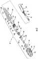
- FIG. 2is a front exploded, perspective view of the connectorized cabling of FIG. 1 .
- FIG. 3is a rear exploded, perspective view of the connectorized cabling of FIG. 1 .
- FIG. 4is a cross-sectional view of the connectorized cabling of FIG. 1 taken along the line 4 - 4 of FIG. 1 .
- FIG. 5is a cross-sectional view of the connectorized cabling of FIG. 1 taken along the line 5 - 5 of FIG. 1 .
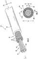
- FIG. 6is an enlarged, fragmentary view of a cable forming a part of the connectorized cabling of FIG. 1 .
- FIG. 7is a cross-sectional view of an optical fiber forming a part of the cable of FIG. 6 .
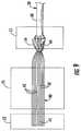
- FIGS. 8-13illustrate method steps for forming the connectorized cabling of FIG. 1 in accordance with method embodiments of the present invention.
- FIG. 14is a fragmentary, perspective view of a cordage in accordance with embodiments of the present invention.
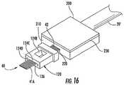
- FIGS. 15-47illustrate method steps for forming a connectorized cable in accordance with further embodiments of the present invention
- spatially relative termssuch as “under”, “below”, “lower”, “over”, “upper” and the like, may be used herein for ease of description to describe one element or features relationship to another element(s) or feature(s) as illustrated in the figures. It will be understood that the spatially relative terms are intended to encompass different orientations of the device in use or operation in addition to the orientation depicted in the figures. For example, if the device in the figures is inverted, elements described as “under” or “beneath” other elements or features would then be oriented “over” the other elements or features. Thus, the exemplary term “under” can encompass both an orientation of over and under. The device may be otherwise oriented (rotated 90 degrees or at other orientations) and the spatially relative descriptors used herein interpreted accordingly.
- the connectorized cabling 10includes a cable 20 and a connector assembly 100 .
- the connector assembly 100may be an optical fiber array or multi-fiber push-on (MPO) type connector (which may also be referred to as an oval connector).
- MPOmulti-fiber push-on
- the connector assembly 100may be a plug connector as shown or, alternatively, a female jack connector with suitable modifications.
- the cable 20may be a breakout or subunit cable from a larger cable including multiple cable subunits and one or more additional jackets.
- the cable 20is constructed as disclosed in co-assigned U.S. patent application Ser. No. 11/412,616, filed Apr. 27, 2006, entitled Fiber Optic Cables and Methods for Forming the Same, the disclosure of which is incorporated herein by reference.
- the cable 20includes generally a plurality of non-buffered optical fibers 42 (collectively forming a fiber bundle 40 ), a plurality of strength members or yarns 52 (collectively forming a yarn bundle 50 ), and a protective jacket 60 .
- the cable 20is round in cross-section and the foregoing groups of components are substantially concentrically positioned about and extend together along a length axis L-L.
- the fiber bundle 40includes at least eight (8) non-buffered optical fibers 42 .
- the fiber bundle 40includes twelve (12) non-buffered optical fibers 42 .
- the optical fibers 110are loose with respect to one another so that they have no particular, fixed relative orientation.
- the optical fiber 42includes a glass fiber 43 , which includes a glass core 43 A and a surrounding glass cladding 43 B.
- the glass fiber 43may be constructed in any suitable manner.
- each of the core 43 A and the cladding 43 Bmay include one or more concentric segments or layers, may be doped, etc.
- the glass fiber 43may be formed of any suitable materials and using any suitable methods.
- a coating layer 44surrounds the cladding 43 B.
- the coating layer 44provides environmental protection for the glass fiber 43 .
- the coating layer 44consists of a single coating layer; however, multiple concentric layers may be applied to form the overall layer 44 .
- the coating layer 44is formed of a UV light-cured acrylate.
- the coating layers 44 of the respective optical fibers 42may have different colors for color-coding purposes.
- the optical fiber 42is an optical fiber constructed as commonly referred to as a “bare optical fiber” or a “non-buffered optical fiber”.
- the overall diameter D 1 of the optical fiber 42is in the range of from about 235 to 265 ⁇ m.
- the thickness T 1 of the coating layer 44is no greater than about 70.5 ⁇ m.
- the overall diameter D 1is between about 235 to 265 ⁇ m and the thickness T 1 of the coating layer 44 is no greater than about 70.5 ⁇ m.
- the diameter D 2 of the core 43 Ais between about 6 and 64 ⁇ m and the diameter D 3 of the cladding 43 B is between about 115 and 135 ⁇ m.
- the bundle 50 of the strength yarns 52at least partially surrounds the optical fiber bundle 40 .
- the strength yarns 52may be formed of any suitable material.
- the strength yarns 52are aramid fibers. Other suitable materials may include fiberglass or polyester.
- the strength yarns 52each have a denier in the range of from about 250 to 3000.
- the strength yarn bundle 50includes between about 2 and 10 ends or strands of the strength yarns 52 (which may each include hundreds of filaments).
- the jacket 60surrounds the yarn bundle 50 and the optical fiber bundle 40 , which reside in a longitudinal passage defined in the jacket 60 .
- the jacket 60may be formed of any suitable material such as a polymeric material.
- the jacket 60is formed of a thermoplastic polymer.
- the thickness of the jacket 60is between about 0.20 and 1.0 mm.
- the outer diameter D 4 ( FIG. 6 ) of the jacket 60i.e., the outer diameter of the cable 20
- the cable 20may be generally regarded as a 3.0 mm cable.
- the inner diameter of the jacket passageis greater than the combined cross-sectional diameter of the optical fiber bundle 40 and the strength yarn bundle 50 so that at least the optical fibers 42 are loose and able to float within the jacket passage (i.e., move freely with respect to the jacket 60 ).
- both the optical fibers 42 and the strength yarns 52are loose and can float within the jacket passage (i.e., can move freely with respect to the jacket 60 ).
- at least a portion of the volume of the jacket passageis not filled by the optical fibers 42 or the strength yarns 52 to allow movement of the optical fibers 42 and the strength yarns 52 within the jacket passage.
- the cable 20may be referred to as a “round, loose tube cable”.
- a non-round (e,g, oval) loose tube fiber optic cablecan be employed instead.
- the connector assembly 100includes a connector housing 105 , a ferrule 120 , epoxy 128 ( FIGS. 4 and 5 ), a ferrule boot 130 , ferrule pins 132 , a pin retainer 134 , a spring 136 , a crimp sleeve 150 , and a strain relief boot 160 .
- the connector housing 105includes a front housing 110 and a rear housing 140 . These components will be discussed in more detail below.
- the front housing 110includes an inner part 112 and an outer part 114 that are relatively slidable.
- a passage 116extends through the front housing 110 .
- the passage 116has a generally oval or rectangular lateral cross-section.
- the front housing 110is substantially rigid.
- the front housing 110may be formed of any suitable material.
- the front housing 110is formed of a thermoplastic.
- the front housing 110is formed of a polymeric material such as polyethermide.
- the front housing 110has a flexural modulus of at least about 2 Gpa.
- the front housing 110may be formed using any suitable method such as molding.
- the ferrule 120defines a cavity 122 and a rear opening 124 A and a top opening 1240 each communicating with the cavity 122 .
- Fiber holes 124 C and pin holes 124 Dextend longitudinally through the ferrule 120 .
- the fiber holes 124 Care configured in side-by-side alignment across the width of the ferrule 120 .
- the ferrule 120has a front face 126 .
- the ferrule 120may be formed using any suitable materials and techniques. According to some embodiments, the ferrule 120 is formed of a polymeric material and, according to some embodiments, a composite material such as a glass filled polymer.
- the ferrule boot 130is tubular and may be formed of rubber.
- the ferrule pins 132 , the pin retainer 134 , the spring 136 and the crimp sleeve 150may be formed of a suitable metal.
- the epoxy 128may be a low stress thermal cure epoxy.
- the rear housing 140includes a front section 142 and a rear section 144 .
- a pair of opposed latch tabs 142 Aextend laterally outwardly from the front section 142 .
- Ribs 144 Aare formed on the rear section 144 .
- a passage 146extends longitudinally through the rear housing 140 from a rear opening 148 A to a front opening 148 B. According to some embodiments, the passage 146 and the front openings 148 A, 148 B are generally oval or rectangular as shown.
- the rear housing 140is substantially rigid.
- the rear housing 140may be formed of any suitable material.
- the rear housing 140is formed of thermoplastic.
- the rear housing 140is formed of a polymeric material such as polyethermide.
- the rear housing 140has a flexural modulus of at least about 2 GPa.
- the rear housing 140may be formed using any suitable technique, such as molding.
- the strain relief boot 160includes a rear section 161 A and a front section 161 B.
- a passage 162extends longitudinally through the strain relief boot 160 from a rear opening 162 A to a front opening 162 B.
- the passage 162has a generally cylindrical rear section 162 C and a generally oval or rectangular front section 162 D.
- Outer ribs 164are formed on the rear section 161 A.
- Opposed top and bottom retention ribs 166extend inwardly into the passage 162 adjacent the front opening 162 B.
- the strain relief boot 160may be formed of any suitable material. According to some embodiments, the strain relief boot 160 is firmed of a polymeric material. According to some embodiments, the strain relief boot 160 is formed of thermoplastic, thermoplastic elastomer, or thermoplastic rubber. According to some embodiments, the strain relief boot 160 has a flexural modulus of between about 0.05 and 0.5 GPa and according to some embodiments, the flexural modulus may be higher with segmented strain relief designed to allow additional flex. The strain relief boot 160 may be formed using any suitable technique. According to some embodiments, the strain relief boot 160 is molded.
- the fibers 42extend through the fiber holes 124 C in the ferrule 120 such that fiber ends 45 are located at the front face 126 of the ferrule 120 .
- the fibers 42are secured in the ferrule 120 by the epoxy 128 .
- the ferrule 120is positioned in the front housing passage 116 such that a portion of the ferrule 120 extends forwardly of the front housing 110 .
- the rear housing 140is coupled to the front housing 110 by the tabs 142 A such that the front section 142 is retained in the passage 116 .
- the ferrule boot 130 and the spring 136surround the fibers 42 .
- the ferrule 120is held in the passage 116 by the pin retainer 134 , which is held in place by the spring 136 , which is braced by the inner housing 140 .
- the pins 132extend through the pin holes 124 D such that they protrude from the front face 126 .
- the pins 132are also held in place by the pin retainer 134 .
- the strength yarn bundle 50 and the jacket 60are secured to the rear housing 140 by the crimp ring 150 . More particularly, segments of the yarn bundle 50 and the jacket 60 are captured between the rear section 144 of the rear housing 140 and the crimp sleeve 150 , which is crimped in place.
- the strain relief boot 160is secured to the rear housing 140 by the ribs 166 , which engage the front edge of the crimp sleeve 150 .
- the rear section 144is positioned in the front passage section 162 D.
- a layer of tape 70 or adhesivemay be present on the fiber bundle 40 within the front housing 110 and/or the rear housing 140 and/or a rear portion of the ferrule inside the epoxy 128 .
- the fiber bundle 40extends from the front face 126 , through the front housing 110 , the ferrule 120 , the ferrule boot 130 , the spring 136 , the rear housing 140 , the crimp sleeve 150 and the strain relief boot 160 .
- the fiber bundle 40has three segments or sections, as follows: a ribbonized fiber section 40 A, a non-ribbonized fiber section 40 B, and a fiber transition section 40 C between the sections 40 A and 4013 .
- the fibers 42are aligned in ordered, side-by-side relation with one another (which may be referred to as a “ribbon configuration”).
- the portions of the fibers 42 in the ribbonized section 40 Aare disposed and extend generally in a single row or common plane as shown to provide a relatively wide, thin construction.
- the fibers 42are generally loose and disposed in various non-mutual planes.
- the fibers 42in the non-ribbonized section 40 B the fibers 42 have a generally round configuration.
- the transition section 40 Cthe fibers 42 are undergoing a transition (i.e., changing, converting, transforming or transiting) from the loose configuration to the ribbonized configuration.
- the ribbonized section 40 Ahas a length L 1 ( FIG. 4 ) of at least about 5 mm. According to some embodiments, the length L 1 is between about 5 and 10 mm. According to sonic embodiments, the transition section 40 C has a length L 2 ( FIG. 4 ) of between about 20 and 30 mm.
- the connector assembly 100has a fixed or rigid region or portion R 1 on the plug side and a strain relief or bendable region or portion R 2 on the cable side.
- the connector assembly 100prevents the segment of the cable 20 therein from being bent
- the rigid portion R 1may extend rearwardly beyond the rear opening of the housing 105 .
- the connector assembly 100may permit non-destructive bending of the cable 20 .
- the strain relief boot 160can be bent with decreasing amounts of strain relief and bend radius limitation from the rear housing 140 to the boot rear opening 162 A.
- the strain relief boot 160may limit the cable bend angle to a gradual bend to thereby prevent or reduce bend related fiber breaks and/or performance losses.
- at least a portion of the strain relief boot 160is semi-rigid to provide controlled fiber bend.
- Termination of the connector assembly 100 on the cable 20 in accordance with embodiments of the present inventionmay be regarded as a round, loose tube fiber cable to array connector direct termination.
- the connector assembly 100receives a round, loose tube fiber cable section and the fiber bundle of the round, loose cable section is converted or reconfigured to a ribbonized fiber bundle within the rigid portion R 1 of the connector assembly 100 .
- the entirety of the ribbonized fiber section 40 Ais contained in the rigid portion R 1 .
- none of the ribbonized fiber bundleis located where it can be bent in use. This termination allows for the benefits of round, loose fiber cabling up to the connector termination.
- a round, loose cable segmentmay be easier to bend, may be bendable with less loss of cable performance, and may have less or no preferential bending limitations.
- termination in accordance with embodiments of the present inventionmay obviate the need for furcation tubing and the related expense, mess and effort.
- the strain relief boot passage 162has a rear section 162 A that is round in cross-section a e., cylindrical) and properly sized to complement the round cable 20 . In this way, the strain relief boot 160 may properly engage the directly terminated round cable to provide suitable strain relief thereto,
- the connectorized cabling 10is a cabling or cordage as shown in FIG. 14 including a length of the cable 20 having a first termination end 20 A and a second opposing termination end 20 B, and a respective connector assembly 100 installed directly on either termination end 20 A, 20 B of the cable 20 .
- the two connector assemblies 100may be configured the same or differently from one another.
- the optical fibers 42extend from the termination end 20 A to the termination end 20 B.
- the strength yarns 52are crimped or otherwise secured directly to both connector assemblies 100 as described herein.
- the strength yarns 52extend continuously from one connector assembly 100 to the other and provide strain relief at both connector assemblies.
- the jacket 60also extends continuously from and is directly secured to each connector assembly 100 .
- Connectorized cables in accordance with embodiments of the present inventionsuch as the connectorized cabling 10 may be formed using methods in accordance with embodiments of the present invention.
- the connectorized cable 10can be assembled as follows.
- the strain relief boot 160 , the crimp sleeve 150 and the rear housing 140are slid onto the cable 20 and out of the way as shown in FIG. 8 (which is a front perspective view).
- the cable 20is cut or trimmed such that a section of the strength member bundle 50 extends beyond the jacket 60 a length L 4 , and a section of the fiber bundle 40 extends beyond the strength yarn bundle 50 a length L 3 .
- the length L 3is at least about 45 mm.
- the length L 4is at least about 2 mm.
- the jacket 60is longitudinally cut on opposed lateral sides to form opposed side slits 62 and opposed top and bottom jacket flaps 64 .
- the length L 5 of the slits 62is at least about 13 mm.
- the jacket flaps 64 and end segments 54 of the yarns 52are folded back onto the jacket 60 as shown in FIG. 9 and secured in place, for example, using a jacket clamp C 1 .
- the fiber bundle 40is then ribbonized using any suitable technique.
- the fibers 42 of the fiber bundle 40are inserted into a fiber alignment tool or ribbonizing fixture F 1 such that the fibers 42 are properly relatively positioned and aligned.
- the fixture F 1may be grooved or non-grooved.
- a fiber clamp C 2may be applied to the free ends 45 of the fibers 42 to temporarily secure the fiber bundle 40 in the ribbonized configuration.
- Tape 70( FIG. 10 ) is applied to the ribbonized segment of the fiber bundle 40 to permanently or semi-permanently secure the segment in ribbonized configuration.
- a liquid adhesive or the likemay be applied to the ribbonized segment of the fiber bundle 40 .
- a Fujikura FAT-04 toolis used to apply an adhesive to the ribbonized fibers.
- the length of the gap between the rear edge of the ribbonizing tape 70 (or adhesive) and the base of the jacket flaps 64is 15 mm or less.
- the end section of the fiber bundle 40is then stripped to remove the tape 70 or adhesive thereon and the fiber coating layer 44 .
- a thermal heat stripping toolsuch as a Fujiura HJS-02 Hot Jacket Stripper in conjunction with a Fujikura FH-12 modified to accommodate the round cable may be used to strip the fibers 42 .
- a bare fiber section 41 Ais formed extending from the fiber free ends 45 to a taped fiber section 41 B.
- the bare fiber section 41 Alikewise has a ribbonized configuration.
- the spring 136 and the ferrule boot 130are slid onto the ribbonized fiber bundle 40 .
- the bare fibers of the fiber section 41 Aare inserted into and through respective ferrule fiber holes 124 C.
- the epoxy 128is injected or otherwise introduced into the ferrule cavity 122 through the top opening 124 B and cured to secure the fibers 42 in the fiber holes 124 C. Portions of the fibers 42 can then be cleaved and the front face 126 may be polished as needed.
- the ferrule pins 132 and the pin retainer 134are installed on the ferrule 120 .
- the front housing 110is mounted on the ferrule 120 .
- the spring 136 and the rear housing 140are slid forward until the rear housing 140 latches with the front housing 110 .
- the jacket flaps 64 and the end sections 54 of the strength yarns 52are folded forward around the rear section 144 of the rear housing 140 .
- the crimp sleeve 150is then slid forward over the jacket flaps 64 , the yarn end sections 54 and the rear housing rear section 144 .
- the crimp sleeve 150is then crimped (e.g., using a suitable tool) to secure the jacket flaps 64 and the yarn ends 54 to the rear section 144 .
- strain relief boot 160is then slid forward on the cable 20 until the retention tabs or ribs 166 engage the front edge of the crimp sleeve 150 ,
- the foregoing procedureis executed in a factory.
- the ribbonized sectionmay include multiple, stacked rows of the fibers in side-by-side alignment.
- a fiber optic cable 20 ′is connectorized without the use of any tape (such as tape 70 of FIG. 10 above) or liquid adhesive. These methods arc described below with reference to FIGS. 15-17 . These methods may be used to attach the connector assembly 100 described above to the fiber optic cable 20 ′.
- the fiber optic cable 20 ′may be identical to the fiber optic cable 20 described above, except that it does not include either the tape 70 or any liquid adhesive.
- operationsmay begin by sliding the strain relief boot 160 , the crimp sleeve 150 , the rear housing 140 and the spring 136 onto the cable 20 ′ and out of the way.
- the cable 20 ′may then be cut such that a section of the fiber bundle 40 extends beyond the both the strength yarn bundle 50 and the jacket 60 .
- the jacket 60is longitudinally cut on opposed lateral sides to form opposed side slits 62 and opposed top and bottom jacket flaps 64 .
- the jacket flaps 64 and end segments of the strength yarn bundle 50are then folded back onto the jacket 60 and may secured in place, for example, using a jacket clamp (not shown). In some embodiments of these methods, the use of this jacket clamp may not be necessary.
- the fiber bundle 40is then ribbonized using a fiber alignment tool 200 such that the fibers 42 are properly positioned and aligned.
- the fiber alignment tool 200may include a base 210 and a cap 230 .
- the base 210may include a groove 220 that receives the fibers 42 .
- a single groove 220may be provided, while in other embodiments, individual grooves (not shown) may be provided for each of the fibers 42 .
- the groove 220may be omitted, and other means (e.g., posts) may be used to facilitate properly positioning and aligning the fibers 42 .
- the cap 230may comprise a hinged cap.
- magnetsmay be included in either the base 210 or the cap 230 . These magnets may be used to hold the cap 230 in place on the base 210 once the fibers 43 have been inserted into the base 210 and properly positioned and aligned. The cap 230 holds the fibers 42 in their proper position and alignment within the base 210 with sufficient force such that the fibers 42 do not move relative to each other during, normal handling, fiber coating stripping and connector assembly. As described below, the fiber alignment tool 200 may be removed once epoxy 128 is inserted into the ferrule boot 130 and cured.
- the base 210 of the fiber alignment tool 200is positioned under the exposed fibers 42 and under the end portion of the jacket 60 (in some embodiments the fiber alignment tool 200 need not be positioned under the jacket 60 ).
- the fibers 42are then positioned, for example, in the groove 220 in the base 210 of the fiber alignment tool 200 .
- the fibers 42transition into a ribbonized configuration in the fiber alignment tool 200 , and are positioned in the proper order, but have a loose configuration behind the fiber alignment, tool 200 .
- the cap 230is closed onto the base 210 such the fiber alignment tool 200 holds the ends of the fibers 42 in the ribbonized configuration.
- a thermal heat stripping tool(or other appropriate device) is used to strip the fiber coating layer 44 from the end sections of the fibers 42 that extend beyond the fiber alignment tool 200 .
- a bare fiber section 41 Ais formed that has a ribbonized configuration.
- the ferrule boot 130may be slid onto the fibers 42 (in the manner discussed below) before this stripping operation is performed.
- epoxy 128is injected or otherwise introduced into the cavity 122 of ferrule 120 through the top opening 124 B.
- a vacuummay be used to draw the epoxy 128 through the ferrule 120 .
- the bare fiber section 41 A of the ribbonized fiber bundle 40is then slid through the epoxy 128 and into the ferrule fiber hole 124 C (this is done while the fiber alignment tool 200 remains in place).
- the ferrule boot 130is then pushed into the rear opening 124 A in the ferrule 120 .
- the epoxy 128is cured to secure the fibers 42 in the fiber hole 124 C. Once the epoxy 128 has been cured, the fiber alignment tool 200 may be removed.
- Portions of the fibers 42can then be cleaved and the front face 126 of ferrule 120 may be polished as needed.
- the ferrule pins 132 and the pin retainer 134may then be installed on the ferrule 120 , and the front housing 110 may be mounted on the ferrule 120 (see FIGS. 2-3 ).
- the spring 136 and the rear housing 140are slid forward until the rear housing 140 latches with the front housing 110 .
- the connectorized cable assemblymay be completed by performing the crimping operations discussed above with respect to FIG. 13 .
- the, spring 136may alternatively be placed over the fibers 42 in front of the split portion of the jacket 60 instead of being placed onto the cable 20 ′ in the manner discussed above with reference to FIG. 15 .
- the alignment tool 200may include a cutout portion (not shown) that receives the spring 136 during assembly of the ferrule 120 .
- the fiber alignment tool 200may be used to hold the fibers 42 in proper alignment until after the epoxy 128 , the bare fiber section 41 A and the ferrule boot 130 are inserted into the ferrule 120 and the epoxy 128 cured, thereby allowing the operation of adding a tape 70 or liquid adhesive to the exposed fibers 42 to be omitted.
- the fibers 42are in ribbonized configuration within the ferrule boot 130 , but have a loose fiber configuration immediately behind the ferrule boot 130 .
- ferrule pins 132may be omitted to form a female connector assembly for use with, the male connector assembly 100 as illustrated.
- the pins 132 of the male connector assembly 100may be received in the pin holes of the female connector assembly to facilitate alignment between the respective mating fiber ends.
- the male and female connector assembliesmay be held together by an adapter, for example.
Landscapes
- Physics & Mathematics (AREA)
- General Physics & Mathematics (AREA)
- Optics & Photonics (AREA)
- Mechanical Coupling Of Light Guides (AREA)
Abstract
Description
Claims (22)
Priority Applications (5)
| Application Number | Priority Date | Filing Date | Title |
|---|---|---|---|
| US16/380,419US10578812B2 (en) | 2005-06-08 | 2019-04-10 | Methods for forming connectorized fiber optic cabling |
| US16/788,042US10859773B2 (en) | 2005-06-08 | 2020-02-11 | Methods for forming connectorized fiber optic cabling |
| US17/090,638US11112568B2 (en) | 2005-06-08 | 2020-11-05 | Connectorized fiber optic cabling assembly |
| US17/396,427US11474309B2 (en) | 2005-06-08 | 2021-08-06 | Connectorized fiber optic cabling assembly |
| US17/929,517US12222560B2 (en) | 2005-06-08 | 2022-09-02 | Connectorized fiber optic cabling assembly |
Applications Claiming Priority (10)
| Application Number | Priority Date | Filing Date | Title |
|---|---|---|---|
| US68849305P | 2005-06-08 | 2005-06-08 | |
| US68849205P | 2005-06-08 | 2005-06-08 | |
| US11/438,647US7537393B2 (en) | 2005-06-08 | 2006-05-22 | Connectorized fiber optic cabling and methods for forming the same |
| US12/423,435US7758257B2 (en) | 2005-06-08 | 2009-04-14 | Methods for forming connectorized fiber optic cabling |
| US12/818,586US8992098B2 (en) | 2005-06-08 | 2010-06-18 | Methods for forming connectorized fiber optic cabling |
| US14/625,647US9229174B2 (en) | 2005-06-08 | 2015-02-19 | Methods for forming connnectorized fiber optic cabling |
| US14/959,289US9690057B2 (en) | 2005-06-08 | 2015-12-04 | Methods for forming connectorized fiber optic cabling |
| US15/613,731US10012805B2 (en) | 2005-06-08 | 2017-06-05 | Methods for forming connectorized fiber optic cabling |
| US16/025,112US10302878B2 (en) | 2005-06-08 | 2018-07-02 | Methods for forming connectorized fiber optic cabling |
| US16/380,419US10578812B2 (en) | 2005-06-08 | 2019-04-10 | Methods for forming connectorized fiber optic cabling |
Related Parent Applications (1)
| Application Number | Title | Priority Date | Filing Date |
|---|---|---|---|
| US16/025,112ContinuationUS10302878B2 (en) | 2005-06-08 | 2018-07-02 | Methods for forming connectorized fiber optic cabling |
Related Child Applications (1)
| Application Number | Title | Priority Date | Filing Date |
|---|---|---|---|
| US16/788,042ContinuationUS10859773B2 (en) | 2005-06-08 | 2020-02-11 | Methods for forming connectorized fiber optic cabling |
Publications (2)
| Publication Number | Publication Date |
|---|---|
| US20190331863A1 US20190331863A1 (en) | 2019-10-31 |
| US10578812B2true US10578812B2 (en) | 2020-03-03 |
Family
ID=68292386
Family Applications (5)
| Application Number | Title | Priority Date | Filing Date |
|---|---|---|---|
| US16/380,419ActiveUS10578812B2 (en) | 2005-06-08 | 2019-04-10 | Methods for forming connectorized fiber optic cabling |
| US16/788,042ActiveUS10859773B2 (en) | 2005-06-08 | 2020-02-11 | Methods for forming connectorized fiber optic cabling |
| US17/090,638ActiveUS11112568B2 (en) | 2005-06-08 | 2020-11-05 | Connectorized fiber optic cabling assembly |
| US17/396,427ActiveUS11474309B2 (en) | 2005-06-08 | 2021-08-06 | Connectorized fiber optic cabling assembly |
| US17/929,517Active2026-11-10US12222560B2 (en) | 2005-06-08 | 2022-09-02 | Connectorized fiber optic cabling assembly |
Family Applications After (4)
| Application Number | Title | Priority Date | Filing Date |
|---|---|---|---|
| US16/788,042ActiveUS10859773B2 (en) | 2005-06-08 | 2020-02-11 | Methods for forming connectorized fiber optic cabling |
| US17/090,638ActiveUS11112568B2 (en) | 2005-06-08 | 2020-11-05 | Connectorized fiber optic cabling assembly |
| US17/396,427ActiveUS11474309B2 (en) | 2005-06-08 | 2021-08-06 | Connectorized fiber optic cabling assembly |
| US17/929,517Active2026-11-10US12222560B2 (en) | 2005-06-08 | 2022-09-02 | Connectorized fiber optic cabling assembly |
Country Status (1)
| Country | Link |
|---|---|
| US (5) | US10578812B2 (en) |
Cited By (1)
| Publication number | Priority date | Publication date | Assignee | Title |
|---|---|---|---|---|
| US10859773B2 (en) | 2005-06-08 | 2020-12-08 | Commscope, Inc. Of North Carolina | Methods for forming connectorized fiber optic cabling |
Families Citing this family (6)
| Publication number | Priority date | Publication date | Assignee | Title |
|---|---|---|---|---|
| MX372735B (en) | 2014-01-13 | 2020-06-19 | Tyco Electronics Shanghai Co Ltd | FIBER OPTIC CONNECTOR. |
| US11353664B1 (en)* | 2019-08-21 | 2022-06-07 | Senko Advanced Components, Inc. | Fiber optic connector |
| US12345925B2 (en) | 2020-05-29 | 2025-07-01 | Commscope Technologies Llc | Telecommunications connector with latch release mechanism |
| US20230341633A1 (en)* | 2020-08-21 | 2023-10-26 | Nitto Denko Corporation | Optical fiber connector member and method of producing the optical fiber connector member |
| WO2023159209A1 (en)* | 2022-02-21 | 2023-08-24 | Commscope Technologies Llc | Fiber optic connector |
| CN114706139B (en)* | 2022-05-09 | 2025-08-19 | 深圳市雅合科技有限公司 | Spring detection device for assembling optical fiber connector |
Citations (108)
| Publication number | Priority date | Publication date | Assignee | Title |
|---|---|---|---|---|
| FR2296190A1 (en) | 1974-12-27 | 1976-07-23 | Int Standard Electric Corp | HIGH RESISTANCE OPTICAL FIBER CABLE |
| US4045121A (en) | 1976-01-22 | 1977-08-30 | The Deutsch Company Electronic Components Division | Optical fiber connector |
| US4102561A (en) | 1975-07-02 | 1978-07-25 | Corning Glass Works | Optical waveguide connector |
| US4252407A (en) | 1977-11-24 | 1981-02-24 | Compagnie Generale D'electricite S.A. | Fibre-to-fibre connector for multifibre optical fibre cables |
| JPS5784405A (en) | 1980-11-13 | 1982-05-26 | Nippon Telegr & Teleph Corp <Ntt> | Optical cable for urgent rehabilitation and optical cable urgent rehabilitation executing method using said cable |
| US4337923A (en) | 1980-09-23 | 1982-07-06 | Smith Jackson A | Fibre optical cable pulling eye |
| US4447121A (en) | 1981-11-06 | 1984-05-08 | Amp Incorporated | Connector for fiber optic member |
| EP0126509A2 (en) | 1983-05-19 | 1984-11-28 | Philips Patentverwaltung GmbH | Optical cable element or cable, and method of making it |
| US4515435A (en) | 1982-08-10 | 1985-05-07 | Cooper Industries, Inc. | Thermally stabilized fiber optic cable |
| JPS6118282A (en) | 1984-06-20 | 1986-01-27 | シーメンス、アクチエンゲゼルシヤフト | X-ray diagnostic equipment |
| US4595839A (en) | 1982-09-30 | 1986-06-17 | Tetra-Tech, Inc. | Bidirectional optical electronic converting connector with integral preamplification |
| US4626067A (en) | 1982-07-29 | 1986-12-02 | Cooper Industries, Inc. | Method of breaking out and terminating fiber optic elements from a multifiber cable |
| US4648688A (en) | 1982-05-24 | 1987-03-10 | Amp Incorporated | Connector for fiber optic member including polishing fixture and method of terminating same |
| US4690498A (en) | 1984-04-19 | 1987-09-01 | Societa Cavi Pirelli S.P.A. | Pressure resistant submarine optical fiber cable |
| JPS6347670A (en) | 1986-08-14 | 1988-02-29 | Mitsubishi Electric Corp | Analog signal input circuit |
| JPS6392908A (en) | 1986-10-07 | 1988-04-23 | Tech Res & Dev Inst Of Japan Def Agency | Emergency connection method of optical cable |
| JPS63167324A (en) | 1986-12-29 | 1988-07-11 | Fujikura Ltd | Method for switching connection of optical fibers |
| US4893893A (en) | 1986-01-31 | 1990-01-16 | American Telephone And Telegraph Co., At&T Bell Laboratories | Strengthened buffered optical fiber |
| US4949894A (en) | 1984-06-07 | 1990-08-21 | Olin Corporation | Method and apparatus for forming ultra-small optical fiber cable assemblies |
| US5073043A (en) | 1990-09-06 | 1991-12-17 | Dimarco Brain A | Cable jacket restraint in optical fiber connectors |
| US5076881A (en) | 1989-07-14 | 1991-12-31 | At&T Bell Laboratories | Apparatus for fabricating an optical fiber ribbon |
| US5125063A (en) | 1990-11-08 | 1992-06-23 | At&T Bell Laboratories | Lightweight optical fiber cable |
| US5160569A (en) | 1991-08-08 | 1992-11-03 | Siecor Corporation | Tool for preparing optical ribbons |
| US5171802A (en) | 1985-11-25 | 1992-12-15 | The Goodyear Tire & Rubber Company | Self-emulsifiable resin powder from acrylic acid polymer |
| JPH05142454A (en) | 1991-03-25 | 1993-06-11 | Corning Inc | Composite buffer cable |
| US5231685A (en) | 1989-11-28 | 1993-07-27 | Kel Corporation | Multi-way electro-optic connector assemblies and optical fiber ferrule assemblies therefor |
| US5252050A (en) | 1992-01-31 | 1993-10-12 | Siecor Corporation | Optical fiber ribbonizer |
| US5402512A (en) | 1993-07-15 | 1995-03-28 | General Motors Corporation | Fiber optic star and transmission assembly |
| US5475782A (en) | 1994-05-16 | 1995-12-12 | Adc Telecommununications, Inc. | Crimp for fiber optic connector |
| JPH085868A (en) | 1994-06-22 | 1996-01-12 | Sumitomo Electric Ind Ltd | Optical cable coupling auxiliary member and optical cable coupling method |
| US5600097A (en) | 1994-11-04 | 1997-02-04 | Lucent Technologies Inc. | Fire resistant cable for use in local area network |
| US5611016A (en) | 1996-06-07 | 1997-03-11 | Lucent Technologies Inc. | Dispersion-balanced optical cable |
| US5630003A (en) | 1995-11-30 | 1997-05-13 | Lucent Technologies Inc. | Loose tube fiber optic cable |
| JPH09243886A (en) | 1996-03-06 | 1997-09-19 | Fujikura Ltd | Non-metallic optical fiber cable |
| US5684910A (en) | 1996-06-24 | 1997-11-04 | Lucent Technologies Inc. | Buffered optical fiber having a strippable buffer layer |
| US5689090A (en) | 1995-10-13 | 1997-11-18 | Lucent Technologies Inc. | Fire resistant non-halogen riser cable |
| US5739473A (en) | 1995-07-31 | 1998-04-14 | Lucent Technologies Inc. | Fire resistant cable for use in local area network |
| US5740295A (en) | 1994-11-02 | 1998-04-14 | Lucent Technologies Inc. | Low fiber count optical cable |
| US5745627A (en) | 1995-12-28 | 1998-04-28 | Lucent Technologies Inc. | Composite cable for fiber-to-the-curb architecture using centralized power |
| US5751879A (en) | 1995-12-28 | 1998-05-12 | Lucent Technologies Inc. | Wound optical fiber cable including robust component cable(s) and a system for manufacture of the cable |
| US5771324A (en) | 1996-05-03 | 1998-06-23 | Laser Power Corporation | Polarization-preserving fiber optic assembly |
| US5806175A (en)* | 1996-12-20 | 1998-09-15 | Siecor Corporation | Crimp assembly for connecting an optical fiber ribbon cord to a connector |
| US5838864A (en) | 1997-04-30 | 1998-11-17 | Lucent Technologies Inc. | Optical cable having an improved strength system |
| US5857051A (en) | 1997-04-21 | 1999-01-05 | Lucent Technologies Inc. | High density riser and plenum breakout cables for indoor and outdoor cable applications |
| US5857046A (en) | 1997-02-12 | 1999-01-05 | The Whitaker Corporation | Strain relief |
| US5867620A (en) | 1997-07-28 | 1999-02-02 | Molex Incorporated | Fixture for fabricating a fiber optic connector ferrule |
| US5878182A (en) | 1997-06-05 | 1999-03-02 | Lucent Technologies Inc. | Optical fiber having a low-dispersion slope in the erbium amplifier region |
| WO1999028773A2 (en) | 1997-12-01 | 1999-06-10 | Telefonaktiebolaget Lm Ericsson (Publ) | Connection means for optical fibres |
| US5913003A (en) | 1997-01-10 | 1999-06-15 | Lucent Technologies Inc. | Composite fiber optic distribution cable |
| US6019521A (en)* | 1998-02-09 | 2000-02-01 | The Whitaker Corporation | Optical fiber connector |
| USRE36592E (en) | 1994-07-01 | 2000-02-29 | Siecor Corporation | Optical receiver stub fitting |
| US6108475A (en) | 1997-12-22 | 2000-08-22 | Lucent Technologies Inc. | Optical fiber cable products having a stress indicating capability and process for making same |
| JP2000235132A (en) | 1999-02-16 | 2000-08-29 | Fujikura Ltd | Optical connector |
| EP1039323A1 (en) | 1999-03-23 | 2000-09-27 | W.L. GORE & ASSOCIATES | Ferrule for optical fibres |
| US6160939A (en) | 1999-03-31 | 2000-12-12 | Lucent Technologies Inc. | Optical cable having a filling material with stable viscosity and yield stress |
| US6178278B1 (en) | 1997-11-13 | 2001-01-23 | Alcatel | Indoor/outdoor dry optical fiber cable |
| US6185351B1 (en) | 1999-10-15 | 2001-02-06 | Lucent Technologies, Inc. | All-dielectric, self-supporting, loose-tube cable with optical fiber ribbons |
| US6185352B1 (en) | 2000-02-24 | 2001-02-06 | Siecor Operations, Llc | Optical fiber ribbon fan-out cables |
| US6205277B1 (en) | 1999-02-19 | 2001-03-20 | Lucent Technologies Inc. | Dry core optical fiber cables for premises applications and methods of manufacture |
| WO2001033276A1 (en) | 1999-10-29 | 2001-05-10 | Corning Cable Systems Llc | Fiber optic drop cable |
| US6264374B1 (en) | 1998-09-09 | 2001-07-24 | Amphenol Corporation | Arrangement for integrating a rectangular fiber optic connector into a cylindrical connector |
| EP1122566A2 (en) | 2000-02-04 | 2001-08-08 | Panduit Corporation | Fiber optic connection system |
| US6305850B1 (en) | 1998-12-31 | 2001-10-23 | Corning Cable Systems Llc | Multifiber alignment adapter and associated fiber optic connector subassembly |
| US6317543B1 (en) | 1999-11-19 | 2001-11-13 | Lucent Technologies Inc. | Cable with lubricated optical fibers and process of lubricating optical fibers |
| US6317542B1 (en) | 1999-09-15 | 2001-11-13 | Lucent Technologies, Inc. | Fiber optic cables with multiple stacks of optical fiber ribbons |
| US6324324B1 (en) | 2000-01-12 | 2001-11-27 | Lucent Technologies Inc. | Communication cable having reduced jacket shrinkage |
| JP2002148480A (en) | 2000-06-23 | 2002-05-22 | Molex Inc | Fiber optic connectors |
| JP2002148481A (en) | 2000-06-23 | 2002-05-22 | Molex Inc | Fiber optic connectors |
| US6442318B1 (en) | 1999-11-23 | 2002-08-27 | Schott Fiber Optics, Inc. | Prefabricated optical fiber ribbon cable for connectorizing with a terminal connector and methods of connectorizing and fabricating the same |
| US6464408B1 (en) | 1998-12-28 | 2002-10-15 | Computer Crafts, Inc. | Fiber optic connectors |
| US20020164130A1 (en) | 2001-05-07 | 2002-11-07 | Elkins Robert B. | Fiber optic module attachment including a fiber locating connector |
| US6485196B2 (en) | 2000-09-14 | 2002-11-26 | The Furukawa Electric Co., Ltd. | Optical fiber cord fixing component |
| US6491445B1 (en) | 1999-12-08 | 2002-12-10 | The Whitaker Corporation | Crimp plug for a connector |
| US20030068147A1 (en) | 2001-10-10 | 2003-04-10 | Alcatel | Optical fiber cable with protection system for optical fiber ribbon stack |
| EP1310814A1 (en) | 2001-11-12 | 2003-05-14 | Corning Cable Systems LLC | A high density optical fibre cable |
| JP2003140013A (en) | 2001-10-30 | 2003-05-14 | Shoden Corp | Fiber optic cable |
| US6567592B1 (en) | 2000-09-29 | 2003-05-20 | Corning Cable Systems Llc | Optical cables with flexible strength sections |
| US20030113079A1 (en) | 2001-12-18 | 2003-06-19 | Alcatel | Fiber optic central tube cable with bundled support member |
| US6585421B1 (en) | 2000-09-15 | 2003-07-01 | Corning Cable Systems Llc | Spacer and strain relief for fiber optic connectors |
| US6655433B1 (en) | 1999-11-30 | 2003-12-02 | Nippon Telegraph And Telephone Corporation | Optical fiber ribbonizing apparatus |
| US20040052474A1 (en) | 2002-09-13 | 2004-03-18 | Fitel U.S.A. Corporation | Robust fiber connector |
| US6738555B1 (en) | 2001-03-28 | 2004-05-18 | Corning Cable Systems Llc | Furcation kit |
| US20040126069A1 (en) | 2002-12-30 | 2004-07-01 | Jong Michael De | Flexible, multi-fiber fiber optic jumper |
| US6775444B1 (en) | 2003-02-28 | 2004-08-10 | Corning Cable Systems Llc | Fiber optic assemblies and methods of making the same |
| US6796721B2 (en) | 2001-11-15 | 2004-09-28 | The Furukawa Electric Co., Ltd. | Optical connector |
| US6807347B2 (en) | 2001-06-25 | 2004-10-19 | Corning Cable Systems Llc | High density fiber optic cable |
| US6816663B2 (en) | 2003-04-07 | 2004-11-09 | Fitel Usa Corp. | Unitary fan-out device for optical ribbon cables |
| US6848838B2 (en) | 2002-09-19 | 2005-02-01 | 3M Innovative Properties Company | Optical fiber plug |
| US20050053343A1 (en) | 2002-11-07 | 2005-03-10 | Ho-Soon Lee | Optical fiber cable for access network |
| US6870996B2 (en) | 2002-09-19 | 2005-03-22 | 3M Innovative Properties Company | Optical fiber plug including fiber positioning holder |
| US6922511B2 (en) | 2003-03-31 | 2005-07-26 | Corning Cable Systems Llc | Fiber optic assemblies and cables having subunits with a security feature |
| JP2005208430A (en) | 2004-01-23 | 2005-08-04 | Showa Electric Wire & Cable Co Ltd | Optical cable |
| US6934451B2 (en) | 2003-06-28 | 2005-08-23 | General Dynamics Advanced Information Systems, Inc. | Mount for use in optical fiber hydrophone array |
| US20050244115A1 (en) | 2004-04-28 | 2005-11-03 | Furukawa Electric North America, Inc. | High count optical fiber cable |
| US6971803B2 (en) | 2004-03-12 | 2005-12-06 | Corning Cable Systems Llc | Multi-fiber ferrule with an alignment portion |
| US20060045452A1 (en) | 2004-08-26 | 2006-03-02 | Williams Martin R | Method and apparatus for reduction of optical coupling between pump lasers and photodetectors in optical amplifiers |
| US7010206B1 (en) | 2004-09-08 | 2006-03-07 | Corning Incorporated | Coated optical fiber and optical fiber coating system including a fast-gelling primary coating |
| US20060093278A1 (en) | 2004-11-03 | 2006-05-04 | Elkins Robert B Ii | Pre-connectorized fiber optic distribution cable having overmolded access location |
| US20060159407A1 (en) | 2005-01-18 | 2006-07-20 | Adc Telecommunications, Inc. | Low shrink telecommunications cable and methods for manufacturing the same |
| US20060159408A1 (en) | 2003-02-19 | 2006-07-20 | Kwang-Il Kim | All-dielectric, self-supporting, loose-tube optical fiber cable |
| US20060198595A1 (en) | 2005-03-07 | 2006-09-07 | Us Conec Ltd. | Transition assembly for high density optical fiber applications and a method of making the same |
| US7149392B2 (en) | 2004-08-30 | 2006-12-12 | Molex Incorporated | Round multi-fiber cable assembly and a method of forming same |
| US20060280413A1 (en) | 2005-06-08 | 2006-12-14 | Commscope Solutions Properties, Llc | Fiber optic cables and methods for forming the same |
| US20070081774A1 (en) | 2005-03-23 | 2007-04-12 | Masayoshi Suzuki | Optical fiber structure and method of manufacturing same |
| US20070183727A1 (en) | 2006-02-03 | 2007-08-09 | Schott Corporation | Conduit bundles including first-type and second-type conduits with disparate properties |
| US20080267569A1 (en) | 2004-11-05 | 2008-10-30 | Alessandro Ginocchio | Water-Blocked Optical Cable and Process for the Production Thereof |
| US7537393B2 (en)* | 2005-06-08 | 2009-05-26 | Commscope, Inc. Of North Carolina | Connectorized fiber optic cabling and methods for forming the same |
| US8992098B2 (en)* | 2005-06-08 | 2015-03-31 | Commscope, Inc. Of North Carolina | Methods for forming connectorized fiber optic cabling |
Family Cites Families (23)
| Publication number | Priority date | Publication date | Assignee | Title |
|---|---|---|---|---|
| JPS54163396A (en) | 1978-06-14 | 1979-12-25 | Noboru Tsuya | Method of producing dielectric substance |
| DE3002473A1 (en) | 1980-01-24 | 1981-09-17 | Teldix Gmbh, 6900 Heidelberg | DETACHABLE COUPLING TO CONNECT, IN PARTICULAR, SEVERAL LIGHTWAVE GUIDES |
| JPS6014011A (en) | 1983-07-04 | 1985-01-24 | Yoshikane Ikutake | Chimney |
| JPS60141011A (en) | 1983-12-28 | 1985-07-26 | Nec Corp | Collector saturation suppression circuit |
| EP0307518B1 (en) | 1984-06-08 | 1993-07-28 | The Whitaker Corporation | High precision fiber optic connectors |
| JPS6118282U (en) | 1984-07-04 | 1986-02-01 | 株式会社日立製作所 | man conveyor tread |
| US4744629A (en) | 1985-08-16 | 1988-05-17 | Augat Inc. | Multifiber optical cable connector |
| JPS6270805A (en) | 1985-09-25 | 1987-04-01 | Furukawa Electric Co Ltd:The | Optical/metal composite cable terminal section |
| JPS6347670U (en) | 1986-09-16 | 1988-03-31 | ||
| US4787706A (en) | 1987-02-03 | 1988-11-29 | American Telephone And Telegraph Company, At&T Bell Laboratories | Duplex optical fiber connector |
| JPS63121572A (en) | 1987-10-12 | 1988-05-25 | Nissan Motor Co Ltd | Rear-wheel steering gear |
| US5016968A (en) | 1989-09-27 | 1991-05-21 | At&T Bell Laboratories | Duplex optical fiber connector and cables terminated therewith |
| US5828804A (en) | 1996-10-15 | 1998-10-27 | Panduit Corp. | Fiber optic connector system |
| US6648520B2 (en) | 2001-09-28 | 2003-11-18 | Corning Cable Systems Llc | Fiber optic plug |
| US6422760B1 (en) | 2001-01-31 | 2002-07-23 | Molex Incorporated | Fiber optic connector module |
| JP3835670B2 (en) | 2001-03-06 | 2006-10-18 | 株式会社フジクラ | Optical fiber branch core with multi-fiber optical connector |
| JP4141684B2 (en) | 2001-12-28 | 2008-08-27 | 株式会社フジクラ | Optical fiber cord with connector and optical fiber cable with connector |
| US6771861B2 (en) | 2002-05-07 | 2004-08-03 | Corning Cable Systems Llc | High performance, flexible optical fiber furcation |
| JP2004219953A (en) | 2003-01-17 | 2004-08-05 | Kddi Submarine Cable Systems Inc | Optical fiber retaining method and apparatus |
| US7001081B2 (en) | 2003-05-22 | 2006-02-21 | 3M Innovative Properties Company | Strain relief boot with flexible extension for guiding fiber optic cable |
| US10578812B2 (en) | 2005-06-08 | 2020-03-03 | Commscope, Inc. Of North Carolina | Methods for forming connectorized fiber optic cabling |
| JP6118282B2 (en) | 2014-02-28 | 2017-04-19 | 富士フイルム株式会社 | Ion exchange membrane and method for producing the same |
| JP6347670B2 (en) | 2014-05-23 | 2018-06-27 | 紀伊産業株式会社 | Overmold container manufacturing equipment |
- 2019
- 2019-04-10USUS16/380,419patent/US10578812B2/enactiveActive
- 2020
- 2020-02-11USUS16/788,042patent/US10859773B2/enactiveActive
- 2020-11-05USUS17/090,638patent/US11112568B2/enactiveActive
- 2021
- 2021-08-06USUS17/396,427patent/US11474309B2/enactiveActive
- 2022
- 2022-09-02USUS17/929,517patent/US12222560B2/enactiveActive
Patent Citations (127)
| Publication number | Priority date | Publication date | Assignee | Title |
|---|---|---|---|---|
| FR2296190A1 (en) | 1974-12-27 | 1976-07-23 | Int Standard Electric Corp | HIGH RESISTANCE OPTICAL FIBER CABLE |
| US4102561A (en) | 1975-07-02 | 1978-07-25 | Corning Glass Works | Optical waveguide connector |
| US4045121A (en) | 1976-01-22 | 1977-08-30 | The Deutsch Company Electronic Components Division | Optical fiber connector |
| US4252407A (en) | 1977-11-24 | 1981-02-24 | Compagnie Generale D'electricite S.A. | Fibre-to-fibre connector for multifibre optical fibre cables |
| US4337923A (en) | 1980-09-23 | 1982-07-06 | Smith Jackson A | Fibre optical cable pulling eye |
| JPS5784405A (en) | 1980-11-13 | 1982-05-26 | Nippon Telegr & Teleph Corp <Ntt> | Optical cable for urgent rehabilitation and optical cable urgent rehabilitation executing method using said cable |
| US4447121A (en) | 1981-11-06 | 1984-05-08 | Amp Incorporated | Connector for fiber optic member |
| US4648688A (en) | 1982-05-24 | 1987-03-10 | Amp Incorporated | Connector for fiber optic member including polishing fixture and method of terminating same |
| US4626067A (en) | 1982-07-29 | 1986-12-02 | Cooper Industries, Inc. | Method of breaking out and terminating fiber optic elements from a multifiber cable |
| US4515435A (en) | 1982-08-10 | 1985-05-07 | Cooper Industries, Inc. | Thermally stabilized fiber optic cable |
| US4595839A (en) | 1982-09-30 | 1986-06-17 | Tetra-Tech, Inc. | Bidirectional optical electronic converting connector with integral preamplification |
| US4659174A (en) | 1983-05-19 | 1987-04-21 | U.S. Philips Corporation | Optical cable element and cable, respectively, and method of manufacturing same |
| JPS6041011A (en) | 1983-05-19 | 1985-03-04 | エヌ・ベ−・フイリツプス・フル−イランペンフアブリケン | Optical cable element, optical cable and manufacturing method thereof |
| EP0126509A2 (en) | 1983-05-19 | 1984-11-28 | Philips Patentverwaltung GmbH | Optical cable element or cable, and method of making it |
| US4690498A (en) | 1984-04-19 | 1987-09-01 | Societa Cavi Pirelli S.P.A. | Pressure resistant submarine optical fiber cable |
| US4949894A (en) | 1984-06-07 | 1990-08-21 | Olin Corporation | Method and apparatus for forming ultra-small optical fiber cable assemblies |
| JPS6118282A (en) | 1984-06-20 | 1986-01-27 | シーメンス、アクチエンゲゼルシヤフト | X-ray diagnostic equipment |
| US5171802A (en) | 1985-11-25 | 1992-12-15 | The Goodyear Tire & Rubber Company | Self-emulsifiable resin powder from acrylic acid polymer |
| US4893893A (en) | 1986-01-31 | 1990-01-16 | American Telephone And Telegraph Co., At&T Bell Laboratories | Strengthened buffered optical fiber |
| JPS6347670A (en) | 1986-08-14 | 1988-02-29 | Mitsubishi Electric Corp | Analog signal input circuit |
| JPS6392908A (en) | 1986-10-07 | 1988-04-23 | Tech Res & Dev Inst Of Japan Def Agency | Emergency connection method of optical cable |
| JPS63167324A (en) | 1986-12-29 | 1988-07-11 | Fujikura Ltd | Method for switching connection of optical fibers |
| US5076881A (en) | 1989-07-14 | 1991-12-31 | At&T Bell Laboratories | Apparatus for fabricating an optical fiber ribbon |
| US5231685A (en) | 1989-11-28 | 1993-07-27 | Kel Corporation | Multi-way electro-optic connector assemblies and optical fiber ferrule assemblies therefor |
| US5073043A (en) | 1990-09-06 | 1991-12-17 | Dimarco Brain A | Cable jacket restraint in optical fiber connectors |
| US5125063A (en) | 1990-11-08 | 1992-06-23 | At&T Bell Laboratories | Lightweight optical fiber cable |
| JPH05142454A (en) | 1991-03-25 | 1993-06-11 | Corning Inc | Composite buffer cable |
| US5160569A (en) | 1991-08-08 | 1992-11-03 | Siecor Corporation | Tool for preparing optical ribbons |
| US5252050A (en) | 1992-01-31 | 1993-10-12 | Siecor Corporation | Optical fiber ribbonizer |
| US5402512A (en) | 1993-07-15 | 1995-03-28 | General Motors Corporation | Fiber optic star and transmission assembly |
| US5475782A (en) | 1994-05-16 | 1995-12-12 | Adc Telecommununications, Inc. | Crimp for fiber optic connector |
| JPH085868A (en) | 1994-06-22 | 1996-01-12 | Sumitomo Electric Ind Ltd | Optical cable coupling auxiliary member and optical cable coupling method |
| USRE36592E (en) | 1994-07-01 | 2000-02-29 | Siecor Corporation | Optical receiver stub fitting |
| US5740295A (en) | 1994-11-02 | 1998-04-14 | Lucent Technologies Inc. | Low fiber count optical cable |
| US5600097A (en) | 1994-11-04 | 1997-02-04 | Lucent Technologies Inc. | Fire resistant cable for use in local area network |
| US5739473A (en) | 1995-07-31 | 1998-04-14 | Lucent Technologies Inc. | Fire resistant cable for use in local area network |
| US5689090A (en) | 1995-10-13 | 1997-11-18 | Lucent Technologies Inc. | Fire resistant non-halogen riser cable |
| US5630003A (en) | 1995-11-30 | 1997-05-13 | Lucent Technologies Inc. | Loose tube fiber optic cable |
| US5745627A (en) | 1995-12-28 | 1998-04-28 | Lucent Technologies Inc. | Composite cable for fiber-to-the-curb architecture using centralized power |
| US5751879A (en) | 1995-12-28 | 1998-05-12 | Lucent Technologies Inc. | Wound optical fiber cable including robust component cable(s) and a system for manufacture of the cable |
| JPH09243886A (en) | 1996-03-06 | 1997-09-19 | Fujikura Ltd | Non-metallic optical fiber cable |
| US5771324A (en) | 1996-05-03 | 1998-06-23 | Laser Power Corporation | Polarization-preserving fiber optic assembly |
| CN1185589A (en) | 1996-06-07 | 1998-06-24 | 卢森特技术有限公司 | Dispersion Balanced Optical Cable |
| US5611016A (en) | 1996-06-07 | 1997-03-11 | Lucent Technologies Inc. | Dispersion-balanced optical cable |
| US5684910A (en) | 1996-06-24 | 1997-11-04 | Lucent Technologies Inc. | Buffered optical fiber having a strippable buffer layer |
| US5806175A (en)* | 1996-12-20 | 1998-09-15 | Siecor Corporation | Crimp assembly for connecting an optical fiber ribbon cord to a connector |
| US5913003A (en) | 1997-01-10 | 1999-06-15 | Lucent Technologies Inc. | Composite fiber optic distribution cable |
| US5857046A (en) | 1997-02-12 | 1999-01-05 | The Whitaker Corporation | Strain relief |
| US5857051A (en) | 1997-04-21 | 1999-01-05 | Lucent Technologies Inc. | High density riser and plenum breakout cables for indoor and outdoor cable applications |
| US5838864A (en) | 1997-04-30 | 1998-11-17 | Lucent Technologies Inc. | Optical cable having an improved strength system |
| US5878182A (en) | 1997-06-05 | 1999-03-02 | Lucent Technologies Inc. | Optical fiber having a low-dispersion slope in the erbium amplifier region |
| US5867620A (en) | 1997-07-28 | 1999-02-02 | Molex Incorporated | Fixture for fabricating a fiber optic connector ferrule |
| US6178278B1 (en) | 1997-11-13 | 2001-01-23 | Alcatel | Indoor/outdoor dry optical fiber cable |
| WO1999028773A2 (en) | 1997-12-01 | 1999-06-10 | Telefonaktiebolaget Lm Ericsson (Publ) | Connection means for optical fibres |
| US6224269B1 (en) | 1997-12-01 | 2001-05-01 | Telefonaktiebolaget Lm Ericsson (Publ) | Connection means for optical fibres |
| JP2001525557A (en) | 1997-12-01 | 2001-12-11 | テレフオンアクチーボラゲツト エル エム エリクソン(パブル) | Optical fiber connection device |
| US6108475A (en) | 1997-12-22 | 2000-08-22 | Lucent Technologies Inc. | Optical fiber cable products having a stress indicating capability and process for making same |
| US6019521A (en)* | 1998-02-09 | 2000-02-01 | The Whitaker Corporation | Optical fiber connector |
| US6264374B1 (en) | 1998-09-09 | 2001-07-24 | Amphenol Corporation | Arrangement for integrating a rectangular fiber optic connector into a cylindrical connector |
| US6464408B1 (en) | 1998-12-28 | 2002-10-15 | Computer Crafts, Inc. | Fiber optic connectors |
| US6554487B2 (en) | 1998-12-28 | 2003-04-29 | Computer Crafts, Inc. | Fiber optic connectors |
| US6305850B1 (en) | 1998-12-31 | 2001-10-23 | Corning Cable Systems Llc | Multifiber alignment adapter and associated fiber optic connector subassembly |
| JP2000235132A (en) | 1999-02-16 | 2000-08-29 | Fujikura Ltd | Optical connector |
| US6205277B1 (en) | 1999-02-19 | 2001-03-20 | Lucent Technologies Inc. | Dry core optical fiber cables for premises applications and methods of manufacture |
| EP1039323A1 (en) | 1999-03-23 | 2000-09-27 | W.L. GORE & ASSOCIATES | Ferrule for optical fibres |
| US6160939A (en) | 1999-03-31 | 2000-12-12 | Lucent Technologies Inc. | Optical cable having a filling material with stable viscosity and yield stress |
| US6317542B1 (en) | 1999-09-15 | 2001-11-13 | Lucent Technologies, Inc. | Fiber optic cables with multiple stacks of optical fiber ribbons |
| US6185351B1 (en) | 1999-10-15 | 2001-02-06 | Lucent Technologies, Inc. | All-dielectric, self-supporting, loose-tube cable with optical fiber ribbons |
| WO2001033276A1 (en) | 1999-10-29 | 2001-05-10 | Corning Cable Systems Llc | Fiber optic drop cable |
| US6256438B1 (en) | 1999-10-29 | 2001-07-03 | Siecor Operations, Llc | Fiber optic drop cable |
| US6317543B1 (en) | 1999-11-19 | 2001-11-13 | Lucent Technologies Inc. | Cable with lubricated optical fibers and process of lubricating optical fibers |
| US6442318B1 (en) | 1999-11-23 | 2002-08-27 | Schott Fiber Optics, Inc. | Prefabricated optical fiber ribbon cable for connectorizing with a terminal connector and methods of connectorizing and fabricating the same |
| US6655433B1 (en) | 1999-11-30 | 2003-12-02 | Nippon Telegraph And Telephone Corporation | Optical fiber ribbonizing apparatus |
| US6491445B1 (en) | 1999-12-08 | 2002-12-10 | The Whitaker Corporation | Crimp plug for a connector |
| US6324324B1 (en) | 2000-01-12 | 2001-11-27 | Lucent Technologies Inc. | Communication cable having reduced jacket shrinkage |
| EP1122566A2 (en) | 2000-02-04 | 2001-08-08 | Panduit Corporation | Fiber optic connection system |
| US6575640B2 (en) | 2000-02-04 | 2003-06-10 | Panduit Corp. | Fiber optic connection system |
| US6185352B1 (en) | 2000-02-24 | 2001-02-06 | Siecor Operations, Llc | Optical fiber ribbon fan-out cables |
| JP2002148480A (en) | 2000-06-23 | 2002-05-22 | Molex Inc | Fiber optic connectors |
| JP2002148481A (en) | 2000-06-23 | 2002-05-22 | Molex Inc | Fiber optic connectors |
| US6485196B2 (en) | 2000-09-14 | 2002-11-26 | The Furukawa Electric Co., Ltd. | Optical fiber cord fixing component |
| US6585421B1 (en) | 2000-09-15 | 2003-07-01 | Corning Cable Systems Llc | Spacer and strain relief for fiber optic connectors |
| US6567592B1 (en) | 2000-09-29 | 2003-05-20 | Corning Cable Systems Llc | Optical cables with flexible strength sections |
| US6738555B1 (en) | 2001-03-28 | 2004-05-18 | Corning Cable Systems Llc | Furcation kit |
| US20020164130A1 (en) | 2001-05-07 | 2002-11-07 | Elkins Robert B. | Fiber optic module attachment including a fiber locating connector |
| US6807347B2 (en) | 2001-06-25 | 2004-10-19 | Corning Cable Systems Llc | High density fiber optic cable |
| US20030068147A1 (en) | 2001-10-10 | 2003-04-10 | Alcatel | Optical fiber cable with protection system for optical fiber ribbon stack |
| JP2003140013A (en) | 2001-10-30 | 2003-05-14 | Shoden Corp | Fiber optic cable |
| US20030091307A1 (en) | 2001-11-12 | 2003-05-15 | Hurley William C. | High density fiber optic cable |
| US20050196113A1 (en) | 2001-11-12 | 2005-09-08 | Hurley William C. | High density fiber optic cable |
| EP1310814A1 (en) | 2001-11-12 | 2003-05-14 | Corning Cable Systems LLC | A high density optical fibre cable |
| US6796721B2 (en) | 2001-11-15 | 2004-09-28 | The Furukawa Electric Co., Ltd. | Optical connector |
| US20030113079A1 (en) | 2001-12-18 | 2003-06-19 | Alcatel | Fiber optic central tube cable with bundled support member |
| US6987916B2 (en) | 2001-12-18 | 2006-01-17 | Alcatel | Fiber optic central tube cable with bundled support member |
| US20040052474A1 (en) | 2002-09-13 | 2004-03-18 | Fitel U.S.A. Corporation | Robust fiber connector |
| US6848838B2 (en) | 2002-09-19 | 2005-02-01 | 3M Innovative Properties Company | Optical fiber plug |
| US6870996B2 (en) | 2002-09-19 | 2005-03-22 | 3M Innovative Properties Company | Optical fiber plug including fiber positioning holder |
| US20050053343A1 (en) | 2002-11-07 | 2005-03-10 | Ho-Soon Lee | Optical fiber cable for access network |
| US20040126069A1 (en) | 2002-12-30 | 2004-07-01 | Jong Michael De | Flexible, multi-fiber fiber optic jumper |
| US6764221B1 (en) | 2002-12-30 | 2004-07-20 | Corning Calde Systems Llc | Flexible, multi-fiber fiber optic jumper |
| US20060159408A1 (en) | 2003-02-19 | 2006-07-20 | Kwang-Il Kim | All-dielectric, self-supporting, loose-tube optical fiber cable |
| US6775444B1 (en) | 2003-02-28 | 2004-08-10 | Corning Cable Systems Llc | Fiber optic assemblies and methods of making the same |
| US6922511B2 (en) | 2003-03-31 | 2005-07-26 | Corning Cable Systems Llc | Fiber optic assemblies and cables having subunits with a security feature |
| US6816663B2 (en) | 2003-04-07 | 2004-11-09 | Fitel Usa Corp. | Unitary fan-out device for optical ribbon cables |
| US6934451B2 (en) | 2003-06-28 | 2005-08-23 | General Dynamics Advanced Information Systems, Inc. | Mount for use in optical fiber hydrophone array |
| JP2005208430A (en) | 2004-01-23 | 2005-08-04 | Showa Electric Wire & Cable Co Ltd | Optical cable |
| US6971803B2 (en) | 2004-03-12 | 2005-12-06 | Corning Cable Systems Llc | Multi-fiber ferrule with an alignment portion |
| US20050244115A1 (en) | 2004-04-28 | 2005-11-03 | Furukawa Electric North America, Inc. | High count optical fiber cable |
| US20060045452A1 (en) | 2004-08-26 | 2006-03-02 | Williams Martin R | Method and apparatus for reduction of optical coupling between pump lasers and photodetectors in optical amplifiers |
| US7149392B2 (en) | 2004-08-30 | 2006-12-12 | Molex Incorporated | Round multi-fiber cable assembly and a method of forming same |
| US7010206B1 (en) | 2004-09-08 | 2006-03-07 | Corning Incorporated | Coated optical fiber and optical fiber coating system including a fast-gelling primary coating |
| US20060093278A1 (en) | 2004-11-03 | 2006-05-04 | Elkins Robert B Ii | Pre-connectorized fiber optic distribution cable having overmolded access location |
| US20080267569A1 (en) | 2004-11-05 | 2008-10-30 | Alessandro Ginocchio | Water-Blocked Optical Cable and Process for the Production Thereof |
| US20060159407A1 (en) | 2005-01-18 | 2006-07-20 | Adc Telecommunications, Inc. | Low shrink telecommunications cable and methods for manufacturing the same |
| US7280732B2 (en) | 2005-03-07 | 2007-10-09 | Us Conec, Ltd. | Transition assembly for high density optical fiber applications and a method of making the same |
| US20060198595A1 (en) | 2005-03-07 | 2006-09-07 | Us Conec Ltd. | Transition assembly for high density optical fiber applications and a method of making the same |
| US20070081774A1 (en) | 2005-03-23 | 2007-04-12 | Masayoshi Suzuki | Optical fiber structure and method of manufacturing same |
| US7537393B2 (en)* | 2005-06-08 | 2009-05-26 | Commscope, Inc. Of North Carolina | Connectorized fiber optic cabling and methods for forming the same |
| US20060280413A1 (en) | 2005-06-08 | 2006-12-14 | Commscope Solutions Properties, Llc | Fiber optic cables and methods for forming the same |
| US7742667B2 (en) | 2005-06-08 | 2010-06-22 | Commscope, Inc. Of North Carolina | Fiber optic cables and methods for forming the same |
| US7758257B2 (en)* | 2005-06-08 | 2010-07-20 | Commscope, Inc. Of North Carolina | Methods for forming connectorized fiber optic cabling |
| US8992098B2 (en)* | 2005-06-08 | 2015-03-31 | Commscope, Inc. Of North Carolina | Methods for forming connectorized fiber optic cabling |
| US9229174B2 (en) | 2005-06-08 | 2016-01-05 | Commscope, Inc. Of North Carolina | Methods for forming connnectorized fiber optic cabling |
| US9690057B2 (en)* | 2005-06-08 | 2017-06-27 | Commscope, Inc. Of North Carolina | Methods for forming connectorized fiber optic cabling |
| US10012805B2 (en) | 2005-06-08 | 2018-07-03 | Commscope, Inc. Of North Carolina | Methods for forming connectorized fiber optic cabling |
| US10302878B2 (en) | 2005-06-08 | 2019-05-28 | Commscope, Inc. Of North Carolina | Methods for forming connectorized fiber optic cabling |
| US20070183727A1 (en) | 2006-02-03 | 2007-08-09 | Schott Corporation | Conduit bundles including first-type and second-type conduits with disparate properties |
Non-Patent Citations (16)
| Title |
|---|
| Cables Plus, LLC, "New Product Release-Chameleon High-Density Fiber Optic Solution," 2007, 1 page. |
| Cables Plus, LLC, "New Product Release—Chameleon High-Density Fiber Optic Solution," 2007, 1 page. |
| Canadian Office Action corresponding to Canadian Application No. 2,610,858; dated Dec. 21, 2011; 4 pages. |
| Canadian Office Action Corresponding to Canadian Application No. 2,610,858; dated Sep. 12, 2011; 3 pages. |
| Corning, Lanscape.RTM. Solutions, "Plug & Play AnyLAN Systems," Dec. 2009, 12 pages. |
| European Office Action for European Patent Application No. 10184040.3, dated Dec. 6, 2013, 5 pages. |
| European Search Report Corresponding to European Application No. 10 18 4040; dated Nov. 7, 2012; 7 pages. |
| International Search Report and the Written Opinion of the International Searching Authority for PCT Application No. PCT/US2006/018027 dated Sep. 28, 2006. |
| Molex, "MTP* Optical Round Ribbon Cable Assemblies," 2004, 2 pages. |
| Oliver et al., "The loose-tube advantage for data center applications," Dec. 2006, pp. 21-23, Cabling Installation & Maintenance. |
| US Conec LTD., "Improved, smaller ribbonizing tool for MT termination," Jul. 2006, 3 pages. |
| US Conec LTD., "MTP.RTM. Brand Connectors," 2009, 3 pages. |
| US Conec LTD., "MTP.RTM. Connector Installation Onto 3 mm Jacketed Round Cable With Loose Fibers," Apr. 15, 2006, 13 pages. |
| US Conec LTD., "New MTP connector kit designed for round cable," Jul. 2006, 3 pages. |
| US Conec.RTM. LTD., "MTP.RTM. Housing Assembly Procedure for Cabled Multifiber Optical Ribbon," EG-0024, Sep. 2001, 4 pages. |
| US Conec.RTM. LTD., "MTP.RTM. Termination Procedure for Cabled Multifiber Optical Ribbon," EG-0023, Jul. 2001, 7 pages. |
Cited By (5)
| Publication number | Priority date | Publication date | Assignee | Title |
|---|---|---|---|---|
| US10859773B2 (en) | 2005-06-08 | 2020-12-08 | Commscope, Inc. Of North Carolina | Methods for forming connectorized fiber optic cabling |
| US11112568B2 (en) | 2005-06-08 | 2021-09-07 | Commscope, Inc. Of North Carolina | Connectorized fiber optic cabling assembly |
| US11474309B2 (en) | 2005-06-08 | 2022-10-18 | Commscope, Inc. Of North Carolina | Connectorized fiber optic cabling assembly |
| US20230105688A1 (en)* | 2005-06-08 | 2023-04-06 | Commscope, Inc. Of North Carolina | Methods for forming connectorized fiber optic cabling |
| US12222560B2 (en)* | 2005-06-08 | 2025-02-11 | Commscope, Inc. Of North Carolina | Connectorized fiber optic cabling assembly |
Also Published As
| Publication number | Publication date |
|---|---|
| US20190331863A1 (en) | 2019-10-31 |
| US11474309B2 (en) | 2022-10-18 |
| US20200257062A1 (en) | 2020-08-13 |
| US20210132301A1 (en) | 2021-05-06 |
| US11112568B2 (en) | 2021-09-07 |
| US10859773B2 (en) | 2020-12-08 |
| US12222560B2 (en) | 2025-02-11 |
| US20220026646A1 (en) | 2022-01-27 |
| US20230105688A1 (en) | 2023-04-06 |
Similar Documents
| Publication | Publication Date | Title |
|---|---|---|
| US10302878B2 (en) | Methods for forming connectorized fiber optic cabling | |
| US7537393B2 (en) | Connectorized fiber optic cabling and methods for forming the same | |
| US11474309B2 (en) | Connectorized fiber optic cabling assembly | |
| US12405430B2 (en) | Fiber optic connector | |
| US9151923B2 (en) | Methods of connectorizing multi-core fiber optic cables and related apparatus | |
| US6764221B1 (en) | Flexible, multi-fiber fiber optic jumper | |
| US11630267B2 (en) | Ferrule boot for optical connectors | |
| US20240061183A1 (en) | Pitch conversion ferrule boot |
Legal Events
| Date | Code | Title | Description |
|---|---|---|---|
| FEPP | Fee payment procedure | Free format text:ENTITY STATUS SET TO UNDISCOUNTED (ORIGINAL EVENT CODE: BIG.); ENTITY STATUS OF PATENT OWNER: LARGE ENTITY | |
| AS | Assignment | Owner name:COMMSCOPE, INC. OF NORTH CAROLINA, NORTH CAROLINA Free format text:ASSIGNMENT OF ASSIGNORS INTEREST;ASSIGNORS:ANDERSON, TIMOTHY W.;CASE, RICHARD L.;REEL/FRAME:049846/0550 Effective date:20100617 | |
| STPP | Information on status: patent application and granting procedure in general | Free format text:NOTICE OF ALLOWANCE MAILED -- APPLICATION RECEIVED IN OFFICE OF PUBLICATIONS | |
| STPP | Information on status: patent application and granting procedure in general | Free format text:PUBLICATIONS -- ISSUE FEE PAYMENT RECEIVED | |
| STCF | Information on status: patent grant | Free format text:PATENTED CASE | |
| AS | Assignment | Owner name:WILMINGTON TRUST, DELAWARE Free format text:SECURITY INTEREST;ASSIGNORS:ARRIS SOLUTIONS, INC.;ARRIS ENTERPRISES LLC;COMMSCOPE TECHNOLOGIES LLC;AND OTHERS;REEL/FRAME:060752/0001 Effective date:20211115 | |
| MAFP | Maintenance fee payment | Free format text:PAYMENT OF MAINTENANCE FEE, 4TH YEAR, LARGE ENTITY (ORIGINAL EVENT CODE: M1551); ENTITY STATUS OF PATENT OWNER: LARGE ENTITY Year of fee payment:4 | |
| AS | Assignment | Owner name:JPMORGAN CHASE BANK, N.A., AS COLLATERAL AGENT, NEW YORK Free format text:PATENT SECURITY AGREEMENT (ABL);ASSIGNORS:ARRIS ENTERPRISES LLC;COMMSCOPE TECHNOLOGIES LLC;COMMSCOPE, INC. OF NORTH CAROLINA;REEL/FRAME:067252/0657 Effective date:20240425 Owner name:JPMORGAN CHASE BANK, N.A., AS COLLATERAL AGENT, NEW YORK Free format text:PATENT SECURITY AGREEMENT (TERM);ASSIGNORS:ARRIS ENTERPRISES LLC;COMMSCOPE TECHNOLOGIES LLC;COMMSCOPE, INC. OF NORTH CAROLINA;REEL/FRAME:067259/0697 Effective date:20240425 | |
| AS | Assignment | Owner name:APOLLO ADMINISTRATIVE AGENCY LLC, NEW YORK Free format text:SECURITY INTEREST;ASSIGNORS:ARRIS ENTERPRISES LLC;COMMSCOPE TECHNOLOGIES LLC;COMMSCOPE INC., OF NORTH CAROLINA;AND OTHERS;REEL/FRAME:069889/0114 Effective date:20241217 | |
| AS | Assignment | Owner name:COMMSCOPE TECHNOLOGIES LLC, NORTH CAROLINA Free format text:RELEASE OF SECURITY INTEREST AT REEL/FRAME 067259/0697;ASSIGNOR:JPMORGAN CHASE BANK, N.A., AS COLLATERAL AGENT;REEL/FRAME:069790/0575 Effective date:20241217 Owner name:COMMSCOPE, INC. OF NORTH CAROLINA, NORTH CAROLINA Free format text:RELEASE OF SECURITY INTEREST AT REEL/FRAME 067259/0697;ASSIGNOR:JPMORGAN CHASE BANK, N.A., AS COLLATERAL AGENT;REEL/FRAME:069790/0575 Effective date:20241217 Owner name:ARRIS ENTERPRISES LLC (F/K/A ARRIS ENTERPRISES, INC.), NORTH CAROLINA Free format text:RELEASE OF SECURITY INTEREST AT REEL/FRAME 067259/0697;ASSIGNOR:JPMORGAN CHASE BANK, N.A., AS COLLATERAL AGENT;REEL/FRAME:069790/0575 Effective date:20241217 |