US10578098B2 - Medical fluid delivery device actuated via motive fluid - Google Patents
Medical fluid delivery device actuated via motive fluidDownload PDFInfo
- Publication number
- US10578098B2 US10578098B2US16/355,101US201916355101AUS10578098B2US 10578098 B2US10578098 B2US 10578098B2US 201916355101 AUS201916355101 AUS 201916355101AUS 10578098 B2US10578098 B2US 10578098B2
- Authority
- US
- United States
- Prior art keywords
- fluid
- pump
- process fluid
- motive
- valve
- Prior art date
- Legal status (The legal status is an assumption and is not a legal conclusion. Google has not performed a legal analysis and makes no representation as to the accuracy of the status listed.)
- Active
Links
Images


Classifications
- F—MECHANICAL ENGINEERING; LIGHTING; HEATING; WEAPONS; BLASTING
- F04—POSITIVE - DISPLACEMENT MACHINES FOR LIQUIDS; PUMPS FOR LIQUIDS OR ELASTIC FLUIDS
- F04B—POSITIVE-DISPLACEMENT MACHINES FOR LIQUIDS; PUMPS
- F04B45/00—Pumps or pumping installations having flexible working members and specially adapted for elastic fluids
- F04B45/04—Pumps or pumping installations having flexible working members and specially adapted for elastic fluids having plate-like flexible members, e.g. diaphragms
- F04B45/053—Pumps having fluid drive
- A—HUMAN NECESSITIES
- A61—MEDICAL OR VETERINARY SCIENCE; HYGIENE
- A61M—DEVICES FOR INTRODUCING MEDIA INTO, OR ONTO, THE BODY; DEVICES FOR TRANSDUCING BODY MEDIA OR FOR TAKING MEDIA FROM THE BODY; DEVICES FOR PRODUCING OR ENDING SLEEP OR STUPOR
- A61M1/00—Suction or pumping devices for medical purposes; Devices for carrying-off, for treatment of, or for carrying-over, body-liquids; Drainage systems
- A61M1/36—Other treatment of blood in a by-pass of the natural circulatory system, e.g. temperature adaptation, irradiation ; Extra-corporeal blood circuits
- A61M1/3621—Extra-corporeal blood circuits
- A61M1/3666—Cardiac or cardiopulmonary bypass, e.g. heart-lung machines
- A—HUMAN NECESSITIES
- A61—MEDICAL OR VETERINARY SCIENCE; HYGIENE
- A61M—DEVICES FOR INTRODUCING MEDIA INTO, OR ONTO, THE BODY; DEVICES FOR TRANSDUCING BODY MEDIA OR FOR TAKING MEDIA FROM THE BODY; DEVICES FOR PRODUCING OR ENDING SLEEP OR STUPOR
- A61M1/00—Suction or pumping devices for medical purposes; Devices for carrying-off, for treatment of, or for carrying-over, body-liquids; Drainage systems
- A61M1/14—Dialysis systems; Artificial kidneys; Blood oxygenators ; Reciprocating systems for treatment of body fluids, e.g. single needle systems for hemofiltration or pheresis
- A—HUMAN NECESSITIES
- A61—MEDICAL OR VETERINARY SCIENCE; HYGIENE
- A61M—DEVICES FOR INTRODUCING MEDIA INTO, OR ONTO, THE BODY; DEVICES FOR TRANSDUCING BODY MEDIA OR FOR TAKING MEDIA FROM THE BODY; DEVICES FOR PRODUCING OR ENDING SLEEP OR STUPOR
- A61M1/00—Suction or pumping devices for medical purposes; Devices for carrying-off, for treatment of, or for carrying-over, body-liquids; Drainage systems
- A61M1/36—Other treatment of blood in a by-pass of the natural circulatory system, e.g. temperature adaptation, irradiation ; Extra-corporeal blood circuits
- A61M1/3621—Extra-corporeal blood circuits
- A61M1/3666—Cardiac or cardiopulmonary bypass, e.g. heart-lung machines
- A61M1/3667—Cardiac or cardiopulmonary bypass, e.g. heart-lung machines with assisted venous return
- A—HUMAN NECESSITIES
- A61—MEDICAL OR VETERINARY SCIENCE; HYGIENE
- A61M—DEVICES FOR INTRODUCING MEDIA INTO, OR ONTO, THE BODY; DEVICES FOR TRANSDUCING BODY MEDIA OR FOR TAKING MEDIA FROM THE BODY; DEVICES FOR PRODUCING OR ENDING SLEEP OR STUPOR
- A61M5/00—Devices for bringing media into the body in a subcutaneous, intra-vascular or intramuscular way; Accessories therefor, e.g. filling or cleaning devices, arm-rests
- A61M5/14—Infusion devices, e.g. infusing by gravity; Blood infusion; Accessories therefor
- A61M5/142—Pressure infusion, e.g. using pumps
- A61M5/14212—Pumping with an aspiration and an expulsion action
- A61M5/14224—Diaphragm type
- A—HUMAN NECESSITIES
- A61—MEDICAL OR VETERINARY SCIENCE; HYGIENE
- A61M—DEVICES FOR INTRODUCING MEDIA INTO, OR ONTO, THE BODY; DEVICES FOR TRANSDUCING BODY MEDIA OR FOR TAKING MEDIA FROM THE BODY; DEVICES FOR PRODUCING OR ENDING SLEEP OR STUPOR
- A61M60/00—Blood pumps; Devices for mechanical circulatory actuation; Balloon pumps for circulatory assistance
- A61M60/10—Location thereof with respect to the patient's body
- A61M60/104—Extracorporeal pumps, i.e. the blood being pumped outside the patient's body
- A61M60/109—Extracorporeal pumps, i.e. the blood being pumped outside the patient's body incorporated within extracorporeal blood circuits or systems
- A61M60/113—Extracorporeal pumps, i.e. the blood being pumped outside the patient's body incorporated within extracorporeal blood circuits or systems in other functional devices, e.g. dialysers or heart-lung machines
- A—HUMAN NECESSITIES
- A61—MEDICAL OR VETERINARY SCIENCE; HYGIENE
- A61M—DEVICES FOR INTRODUCING MEDIA INTO, OR ONTO, THE BODY; DEVICES FOR TRANSDUCING BODY MEDIA OR FOR TAKING MEDIA FROM THE BODY; DEVICES FOR PRODUCING OR ENDING SLEEP OR STUPOR
- A61M60/00—Blood pumps; Devices for mechanical circulatory actuation; Balloon pumps for circulatory assistance
- A61M60/30—Medical purposes thereof other than the enhancement of the cardiac output
- A61M60/36—Medical purposes thereof other than the enhancement of the cardiac output for specific blood treatment; for specific therapy
- A61M60/38—Blood oxygenation
- A—HUMAN NECESSITIES
- A61—MEDICAL OR VETERINARY SCIENCE; HYGIENE
- A61M—DEVICES FOR INTRODUCING MEDIA INTO, OR ONTO, THE BODY; DEVICES FOR TRANSDUCING BODY MEDIA OR FOR TAKING MEDIA FROM THE BODY; DEVICES FOR PRODUCING OR ENDING SLEEP OR STUPOR
- A61M60/00—Blood pumps; Devices for mechanical circulatory actuation; Balloon pumps for circulatory assistance
- A61M60/40—Details relating to driving
- A61M60/424—Details relating to driving for positive displacement blood pumps
- A61M60/427—Details relating to driving for positive displacement blood pumps the force acting on the blood contacting member being hydraulic or pneumatic
- A61M60/43—Details relating to driving for positive displacement blood pumps the force acting on the blood contacting member being hydraulic or pneumatic using vacuum at the blood pump, e.g. to accelerate filling
- F—MECHANICAL ENGINEERING; LIGHTING; HEATING; WEAPONS; BLASTING
- F04—POSITIVE - DISPLACEMENT MACHINES FOR LIQUIDS; PUMPS FOR LIQUIDS OR ELASTIC FLUIDS
- F04B—POSITIVE-DISPLACEMENT MACHINES FOR LIQUIDS; PUMPS
- F04B23/00—Pumping installations or systems
- F04B23/04—Combinations of two or more pumps
- F—MECHANICAL ENGINEERING; LIGHTING; HEATING; WEAPONS; BLASTING
- F04—POSITIVE - DISPLACEMENT MACHINES FOR LIQUIDS; PUMPS FOR LIQUIDS OR ELASTIC FLUIDS
- F04B—POSITIVE-DISPLACEMENT MACHINES FOR LIQUIDS; PUMPS
- F04B43/00—Machines, pumps, or pumping installations having flexible working members
- F04B43/02—Machines, pumps, or pumping installations having flexible working members having plate-like flexible members, e.g. diaphragms
- F04B43/025—Machines, pumps, or pumping installations having flexible working members having plate-like flexible members, e.g. diaphragms two or more plate-like pumping members in parallel
- F—MECHANICAL ENGINEERING; LIGHTING; HEATING; WEAPONS; BLASTING
- F04—POSITIVE - DISPLACEMENT MACHINES FOR LIQUIDS; PUMPS FOR LIQUIDS OR ELASTIC FLUIDS
- F04B—POSITIVE-DISPLACEMENT MACHINES FOR LIQUIDS; PUMPS
- F04B43/00—Machines, pumps, or pumping installations having flexible working members
- F04B43/02—Machines, pumps, or pumping installations having flexible working members having plate-like flexible members, e.g. diaphragms
- F04B43/06—Pumps having fluid drive
- F04B43/073—Pumps having fluid drive the actuating fluid being controlled by at least one valve
- F04B43/0733—Pumps having fluid drive the actuating fluid being controlled by at least one valve with fluid-actuated pump inlet or outlet valves; with two or more pumping chambers in series
- F—MECHANICAL ENGINEERING; LIGHTING; HEATING; WEAPONS; BLASTING
- F04—POSITIVE - DISPLACEMENT MACHINES FOR LIQUIDS; PUMPS FOR LIQUIDS OR ELASTIC FLUIDS
- F04B—POSITIVE-DISPLACEMENT MACHINES FOR LIQUIDS; PUMPS
- F04B43/00—Machines, pumps, or pumping installations having flexible working members
- F04B43/02—Machines, pumps, or pumping installations having flexible working members having plate-like flexible members, e.g. diaphragms
- F04B43/06—Pumps having fluid drive
- F04B43/073—Pumps having fluid drive the actuating fluid being controlled by at least one valve
- F04B43/0736—Pumps having fluid drive the actuating fluid being controlled by at least one valve with two or more pumping chambers in parallel
- F—MECHANICAL ENGINEERING; LIGHTING; HEATING; WEAPONS; BLASTING
- F04—POSITIVE - DISPLACEMENT MACHINES FOR LIQUIDS; PUMPS FOR LIQUIDS OR ELASTIC FLUIDS
- F04B—POSITIVE-DISPLACEMENT MACHINES FOR LIQUIDS; PUMPS
- F04B45/00—Pumps or pumping installations having flexible working members and specially adapted for elastic fluids
- F04B45/04—Pumps or pumping installations having flexible working members and specially adapted for elastic fluids having plate-like flexible members, e.g. diaphragms
- F04B45/043—Pumps or pumping installations having flexible working members and specially adapted for elastic fluids having plate-like flexible members, e.g. diaphragms two or more plate-like pumping flexible members in parallel
- F—MECHANICAL ENGINEERING; LIGHTING; HEATING; WEAPONS; BLASTING
- F04—POSITIVE - DISPLACEMENT MACHINES FOR LIQUIDS; PUMPS FOR LIQUIDS OR ELASTIC FLUIDS
- F04B—POSITIVE-DISPLACEMENT MACHINES FOR LIQUIDS; PUMPS
- F04B45/00—Pumps or pumping installations having flexible working members and specially adapted for elastic fluids
- F04B45/04—Pumps or pumping installations having flexible working members and specially adapted for elastic fluids having plate-like flexible members, e.g. diaphragms
- F04B45/053—Pumps having fluid drive
- F04B45/0536—Pumps having fluid drive the actuating fluid being controlled by one or more valves
- F—MECHANICAL ENGINEERING; LIGHTING; HEATING; WEAPONS; BLASTING
- F04—POSITIVE - DISPLACEMENT MACHINES FOR LIQUIDS; PUMPS FOR LIQUIDS OR ELASTIC FLUIDS
- F04B—POSITIVE-DISPLACEMENT MACHINES FOR LIQUIDS; PUMPS
- F04B53/00—Component parts, details or accessories not provided for in, or of interest apart from, groups F04B1/00 - F04B23/00 or F04B39/00 - F04B47/00
- F04B53/10—Valves; Arrangement of valves
- F04B53/109—Valves; Arrangement of valves inlet and outlet valve forming one unit
- F—MECHANICAL ENGINEERING; LIGHTING; HEATING; WEAPONS; BLASTING
- F04—POSITIVE - DISPLACEMENT MACHINES FOR LIQUIDS; PUMPS FOR LIQUIDS OR ELASTIC FLUIDS
- F04B—POSITIVE-DISPLACEMENT MACHINES FOR LIQUIDS; PUMPS
- F04B7/00—Piston machines or pumps characterised by having positively-driven valving
- F04B7/02—Piston machines or pumps characterised by having positively-driven valving the valving being fluid-actuated
- F04B7/0266—Piston machines or pumps characterised by having positively-driven valving the valving being fluid-actuated the inlet and discharge means being separate members
- F04B7/0275—Piston machines or pumps characterised by having positively-driven valving the valving being fluid-actuated the inlet and discharge means being separate members and being deformable, e.g. membranes
- A—HUMAN NECESSITIES
- A61—MEDICAL OR VETERINARY SCIENCE; HYGIENE
- A61M—DEVICES FOR INTRODUCING MEDIA INTO, OR ONTO, THE BODY; DEVICES FOR TRANSDUCING BODY MEDIA OR FOR TAKING MEDIA FROM THE BODY; DEVICES FOR PRODUCING OR ENDING SLEEP OR STUPOR
- A61M2202/00—Special media to be introduced, removed or treated
- A61M2202/04—Liquids
- A61M2202/0413—Blood
- A—HUMAN NECESSITIES
- A61—MEDICAL OR VETERINARY SCIENCE; HYGIENE
- A61M—DEVICES FOR INTRODUCING MEDIA INTO, OR ONTO, THE BODY; DEVICES FOR TRANSDUCING BODY MEDIA OR FOR TAKING MEDIA FROM THE BODY; DEVICES FOR PRODUCING OR ENDING SLEEP OR STUPOR
- A61M60/00—Blood pumps; Devices for mechanical circulatory actuation; Balloon pumps for circulatory assistance
- A61M60/80—Constructional details other than related to driving
- A61M60/845—Constructional details other than related to driving of extracorporeal blood pumps
- A61M60/847—Constructional details other than related to driving of extracorporeal blood pumps arranged in a cassette
- A—HUMAN NECESSITIES
- A61—MEDICAL OR VETERINARY SCIENCE; HYGIENE
- A61M—DEVICES FOR INTRODUCING MEDIA INTO, OR ONTO, THE BODY; DEVICES FOR TRANSDUCING BODY MEDIA OR FOR TAKING MEDIA FROM THE BODY; DEVICES FOR PRODUCING OR ENDING SLEEP OR STUPOR
- A61M60/00—Blood pumps; Devices for mechanical circulatory actuation; Balloon pumps for circulatory assistance
- A61M60/80—Constructional details other than related to driving
- A61M60/845—Constructional details other than related to driving of extracorporeal blood pumps
- A61M60/851—Valves
- A—HUMAN NECESSITIES
- A61—MEDICAL OR VETERINARY SCIENCE; HYGIENE
- A61N—ELECTROTHERAPY; MAGNETOTHERAPY; RADIATION THERAPY; ULTRASOUND THERAPY
- A61N5/00—Radiation therapy
- A61N5/10—X-ray therapy; Gamma-ray therapy; Particle-irradiation therapy
- A61N5/1001—X-ray therapy; Gamma-ray therapy; Particle-irradiation therapy using radiation sources introduced into or applied onto the body; brachytherapy
- A61N2005/1019—Sources therefor
- A61N2005/1021—Radioactive fluid
- F—MECHANICAL ENGINEERING; LIGHTING; HEATING; WEAPONS; BLASTING
- F04—POSITIVE - DISPLACEMENT MACHINES FOR LIQUIDS; PUMPS FOR LIQUIDS OR ELASTIC FLUIDS
- F04B—POSITIVE-DISPLACEMENT MACHINES FOR LIQUIDS; PUMPS
- F04B2201/00—Pump parameters
- F04B2201/06—Valve parameters
- F04B2201/0601—Opening times
- F—MECHANICAL ENGINEERING; LIGHTING; HEATING; WEAPONS; BLASTING
- F04—POSITIVE - DISPLACEMENT MACHINES FOR LIQUIDS; PUMPS FOR LIQUIDS OR ELASTIC FLUIDS
- F04B—POSITIVE-DISPLACEMENT MACHINES FOR LIQUIDS; PUMPS
- F04B2201/00—Pump parameters
- F04B2201/06—Valve parameters
- F04B2201/0605—Leakage over a valve
- Y—GENERAL TAGGING OF NEW TECHNOLOGICAL DEVELOPMENTS; GENERAL TAGGING OF CROSS-SECTIONAL TECHNOLOGIES SPANNING OVER SEVERAL SECTIONS OF THE IPC; TECHNICAL SUBJECTS COVERED BY FORMER USPC CROSS-REFERENCE ART COLLECTIONS [XRACs] AND DIGESTS
- Y10—TECHNICAL SUBJECTS COVERED BY FORMER USPC
- Y10T—TECHNICAL SUBJECTS COVERED BY FORMER US CLASSIFICATION
- Y10T137/00—Fluid handling
- Y10T137/7722—Line condition change responsive valves
- Y10T137/7837—Direct response valves [i.e., check valve type]
- Y10T137/7838—Plural
- Y10T137/7843—Integral resilient member forms plural valves
Definitions
- Certain embodiments described hereinrelate generally to the field of fluid transfer. More particularly, some embodiments described herein relate to fluid transfer having a relatively small amount or no amount of impurities introduced to the fluid being transferred and/or relatively little or no damage to the fluid being transferred.
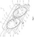
- FIG. 1is a perspective view of an embodiment of a double diaphragm blood pump.
- FIG. 2is an exploded perspective view of the double diaphragm blood pump of FIG. 1 .
- FIG. 3is a perspective view of an inner side of an embodiment of a valve plate.
- FIG. 4is a plan view of one side of an embodiment of a pump body with a portion of the interior of the pump body shown in phantom and a portion of an opposite side of the pump body shown in phantom.
- FIG. 5is a perspective view of the inner side of an embodiment of a chamber plate with interior features thereof shown in phantom.
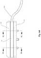
- FIG. 6Ais a perspective view of an embodiment of diaphragm media before regions have been formed.
- FIG. 6Bis a perspective view of the diaphragm media of FIG. 6A after the regions have been formed.
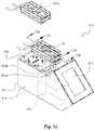
- FIG. 7is an exploded perspective view of an embodiment of a forming fixture used to form the regions in the diaphragm.
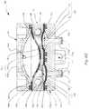
- FIG. 8Ais a cross-sectional view of a forming fixture after a diaphragm media has been loaded to form the regions in the chamber diaphragm.
- FIG. 8Bis a cross-sectional view such as the view in FIG. 8A showing the forming fixture after the regions in the diaphragm media have been formed.
- FIG. 9Ais a side view of the double diaphragm pump of FIG. 1 which shows cutting lines 9 B- 9 B and 9 C- 9 C.
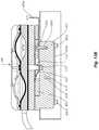
- FIG. 9Bis a cross-sectional view of the double diaphragm pump of FIG. 1 taken along cutting line 9 B- 9 B in FIG. 9A .
- FIG. 9Cis a cross-sectional view of the double diaphragm pump of FIG. 1 taken along cutting line 9 C- 9 C in FIG. 9A .
- FIG. 10is a cross-sectional view of another embodiment of the double diaphragm pump of FIG. 1 taken along cutting line 9 B- 9 B in FIG. 9A showing valve bypass passages.
- FIG. 11is a cross-sectional perspective view of another embodiment of a diaphragm pump.
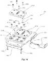
- FIG. 12is a partially exploded perspective view of two double diaphragm blood pumps configured for operative association with a reusable pump control system.
- FIG. 13Ais a partial cross-sectional view of a double diaphragm pump and manifold taken along cutting line 13 A- 13 A in FIG. 12 .
- FIG. 13Bis a partial cross-sectional view of a double diaphragm pump and manifold taken along cutting line 13 B- 13 B in FIG. 12 .
- FIG. 14is a partially exploded perspective view of an embodiment of a manifold mounting assembly.
- FIG. 15is a perspective view of an embodiment of a manifold base with a portion of the interior features of the manifold base shown in phantom.
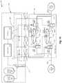
- FIG. 16is a schematic view of an embodiment of a double diaphragm pump as used in a method and system for transferring fluid.
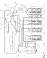
- FIG. 17is a schematic view of an embodiment of a cardiopulmonary by-pass system that includes multiple double diaphragm pumps.
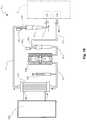
- FIG. 18is a schematic view of an embodiment of a heart-assist system using an embodiment of the double diaphragm pump.
- FIG. 19is a schematic view of an embodiment of a hemodialysis system using an embodiment of the double diaphragm pump to effect flow through the system.
- FIG. 20is a chart showing an example of the pressure over time of blood entering and also of blood exiting an embodiment of a double diaphragm pump of the system depicted in FIG. 17 when configured for relatively constant flow operation.
- FIG. 21is a chart showing an example of the pressure over time of blood entering and also of blood exiting an embodiment of a double diaphragm pump of the system depicted in FIG. 18 when the pump is configured for pulsatile outflow operation and relatively constant inflow operation.
- FIG. 22Ais a chart showing an example of the pressure over time of blood entering and also of blood exiting an embodiment of a double diaphragm pump of the system depicted in FIG. 19 , as well as the pressure over time of blood exiting the dialyzer, when the pump is configured for use in a hemodialysis procedure and controlled for relatively constant inflow operation and relatively constant outflow operation.
- FIG. 22Bis a chart showing an example of the pressure over time of blood entering and also of blood exiting the double diaphragm pump in the system depicted in FIG. 19 , as well as the pressure over time of blood exiting the dialyzer, when the pump is configured for use in a hemodialysis procedure and controlled for relatively constant inflow operation and pulsatile outflow operation.
- first inlet valve portalfor fluid communication between inlet channel 138 i and first inlet valve seat 111 i
- first outlet valve portalfor fluid communication between first outlet valve seat 111 o and outlet channel 138 o
- FIGS. 1-6B and 9A-11Various views of an illustrative embodiment of a pump are provided in FIGS. 1-6B and 9A-11 .
- FIGS. 7-8Brelate to an embodiment of a forming fixture used to shape regions of a chamber diaphragm which can be used in a pump.
- An embodiment of pumping system utilizing a double diaphragm pumpis shown in FIGS. 12-15 .
- FIG. 16provides a schematic view of an embodiment of a system utilizing a double diaphragm pump.
- the schematic views provided in FIGS. 17-19illustrate various applications of embodiments of double diaphragm pumps in medical applications in which blood is pumped.
- FIG. 2the chamber diaphragms illustrated in FIG. 2 will be referred to as 140 a and 140 b , and various diaphragm blood pumps are referred to in FIG. 17 as 100 b , 100 c , 100 d , etc.
- a pump body in one embodimentis referred to in FIG. 9C as 110 and a pump body in another embodiment is referred to in FIG. 10 as 110 ′.
- Certain diaphragm pumpscan have application as a single use disposable medical blood pump.
- a pumpcan be used to move blood through an extracorporeal circuit.
- An advantage of pumping blood with certain pumps as described hereinis that, in various embodiments, a relatively small amount, a minimal amount, a negligible amount, or even no amount of synthetic pump material particles is released into the flow of blood that is caused by rubbing, sliding, or straining of materials typically used in other types of pump mechanisms to energize fluid flow.
- Synthetic particulates generated by certain pumps that move fluids to and from a patienthave the potential to create adverse health effects including embolisms or microembolisms in the vascular system. Further, the toxicity of materials introduced or generated by such pumps can be delivered to the patient and can be left residing in the vascular system of the patient.
- a pneumatically actuated diaphragm pumpcan be advantageous because of the inherent control that may be achieved for delivering fluids within physiologically acceptable pressure ranges. For example, if a blockage occurs in the process fluid lines connected to an embodiment of a pump, some embodiments of the pump may only generate pressure in the process fluid at a level that is at or near those of the motive fluid pressures that are driving the pump. In the case of pumping blood, such a pump can reduce or eliminate excessive pressures or high vacuums in the fluid lines that can potentially damage blood or cause air embolisms by out-gassing the blood under high suction levels.
- Some embodiments of pumping systems that may be used in single-use disposable medical applicationscan advantageously be comprised of a removable and/or separable disposable pumping component and a reusable pump control system.
- the disposable pumping componentcan be packaged and pre-sterilized for use in a medical application related to an individual patient.
- the disposable pumping componentcan be coupled in operative association with the reusable pump control system for a single patient during a medical application, and then removed and disposed.
- the reusable pump control systemcan be isolated from the flow of biological fluids and may selectively control and operate a plurality of disposable pumping components-one or more for each of a multiple number of patients or applications, in some instances-without being sterilized between uses.
- the removable/disposable pumping componentmay include pump chambers, inlet and outlet valves, inlet and outlet lines, and other components which are in contact with the blood or biological fluid.
- the removable/disposable pumping componentcomprises a double diaphragm pump.
- the double diaphragm pumpcan be configured and designed with a plurality of pump chambers, flow paths, valves, etc. that are specifically designed for a particular application.
- some embodiments of double diaphragm pumpscan be configured for use in such medical applications as cardiopulmonary bypass, surgical perfusion support, heart assist, and hemodialysis, as further described below.
- double diaphragm pumpsalso enable fluids to be transferred in a wide variety of other fields.
- such pumpscan be used in the transfer of high purity process fluids.
- Some embodiments of double diaphragm pumpscan be advantageous in transferring high purity process fluids, as the pump avoids, minimizes, or otherwise reduces the introduction or generation of contaminants or particulate matter that can be transferred downstream by reducing or eliminating rubbing and sliding components within the pump. Downstream transfer of contaminants or particulate matter may effect the desired outcome of using the high purity process fluid.
- some pumpscan be operated to gently move fluid from a source to a destination.
- FIG. 1provides a perspective view of an embodiment of a double diaphragm pump at 100 .
- the pump 100can comprise a plurality of housing members or housing components, which in some embodiments may be substantially rigid, as discussed below.
- the housing memberscomprise a pump body 110 , a chamber plate 160 and a valve plate 170 .
- the pump 100further comprises a plurality of diaphragms.
- the pump 100comprises one or more chamber diaphragms 140 a , 140 b , which can be located between chamber plate 160 and pump body 110 , and further comprises one or more valve diaphragms 150 a , 150 b , which can be located between valve plate 170 and pump body 110 .
- the chamber diaphragms 140 a, b and valve diaphragms 150 a, bare not identified in FIG. 1 but are shown in FIGS. 2, 9B, and 9C . While these diaphragms may not necessarily extend to the perimeter of pump body 110 , chamber plate 160 , or valve plate 170 , in some embodiments, the media can extend to the perimeter or beyond so that the media protrudes beyond an outer edge of the pump body 110 . As further discussed below, in some embodiments, manifold cover plate 190 seals or closes motive fluid passages defined by chamber plate 160 .
- FIG. 1 and FIG. 4show features related to the inlet and outlet lines for the passage of process fluid through the pump body 110 .
- inlet line 180 iis connected with inlet channel 138 i and outlet line 180 o is connected with outlet channel 138 o , as shown.
- Inlet channel 138 i and outlet channel 138 oare shown in more detail in FIG. 4 , FIGS. 9B-10 and FIG. 16 .
- representative connections between inlet line 180 i and inlet channel 138 i and between outlet line 180 o and outlet channel 138 oare shown. Similar connections can be made to other external fluid lines or devices.
- the connection between these componentscan include solvent bonding, adhesives, mechanical fittings (including barbed nipple tube fittings), or other methods well known in the art.
- FIG. 2Some of the components which comprise the valves and the pump chambers are shown in FIG. 2 , however, the valves and the pump chambers are not identified in FIG. 2 , as this figure represents an exploded perspective view of a double diaphragm pump 100 .
- certain embodiments of the double diaphragm pump 100can comprise a first inlet valve 101 i , first outlet valve 101 o , second inlet valve 102 i , second outlet valve 102 o , first pump chamber 103 a , and second pump chamber 103 b .
- FIG. 9B-9C and FIG. 10certain embodiments of the double diaphragm pump 100 can comprise a first inlet valve 101 i , first outlet valve 101 o , second inlet valve 102 i , second outlet valve 102 o , first pump chamber 103 a , and second pump chamber 103 b .
- valve plate 170comprises grooves 177 i , 177 o , 178 i , and 178 o (see FIG. 3 ) for receiving o-rings 192 a - d .
- chamber plate 160can comprise grooves for receiving o-rings 193 a, b.
- the diaphragms 140 a, b and 150 a, b and pump body 110can be fabricated with similar materials that will bond together when heated.
- fluorinated ethylene propylene (FEP) materialscan be used for both of the diaphragms 140 a, b , 150 a, b and the pump body 110 , and heat can be used to bond the diaphragms to the body.
- heat sealable materialsthat can be used for both of the diaphragms 140 a, b , 150 a, b and the pump body 110 include polyvinylchloride (PVC), polyurethane (PU), and polypropylene (PP).
- PVCpolyvinylchloride
- PUpolyurethane
- PPpolypropylene
- an adhesivesuch as Scotch Weld Acrylic DP-8005 adhesive manufactured by 3M-Industrial Business, Industrial Adhesives and Tapes Division, St. Paul, Minn., is used to attach the chamber plate 160 assembly posts 169 a - d and air bosses 162 a, b (see, e.g., FIG. 5 ) to the valve plate 170 assembly holes 179 a - f (see, e.g., FIG. 3 ).
- Components of a double diaphragm pump 100can be assembled together in any other suitable manner, such as via mechanical fasteners (for example nuts and bolts, clamps, screws, etc.); adhesives; welding; bonding; or other mechanisms. These mechanisms are all examples of means for maintaining the plates and body together and sealing chambers created between the plates and body.
- FIG. 2provides the best view of the chamber diaphragms 140 a, b and valve diaphragms 150 a, b .
- each diaphragm 140 a, b and 150 a, bhas a specific region corresponding with a particular chamber. In some embodiments, the regions are preformed or pre-shaped prior to assembly of the pump 100 .
- a single diaphragmis used between pump body 110 and chamber plate 160 and/or a single diaphragm is used between pump body 110 and valve plate 170 . In other embodiments, two or more diaphragms are utilized between one or more sets of neighboring components, which can provide a pump 100 with one or more redundant layers for safety purposes.
- each chamber or valveuses a separate diaphragm or diaphragms that are not integrated into a multi-chamber diaphragm.
- the separate diaphragmscan also include preformed or pre-shaped actuation regions.
- the actuation regionsare configured to move between a natural shape and an inversion of the natural shape without significant stretching, as further discussed below.
- the actuation regionscan be configured to flex, in some embodiments. Methods for forming diaphragms with pre-shaped regions are discussed below with reference to FIGS. 6A, 6B, 7, 8A, and 8B .
- the preformed actuation regions of chamber diaphragm 140 ainclude first pump chamber region 141 a and second pump chamber region 141 b .
- the preformed actuation regions of valve diaphragm 150 ainclude first inlet valve region 151 i , first outlet valve region 151 o , second inlet valve region 152 i , and second outlet valve region 152 o .
- Each media 140 a, b and 150 a, bcan also have holes 142 a - f (see FIG. 6A ) for manufacturing and assembly, as further discussed below.
- first pump chamber 103 ais divided by first pump chamber region 141 a into first pump chamber cavity 113 a and first actuation cavity 161 a .
- second pump chamber 103 bis divided by second pump chamber region 141 b into second pump chamber cavity 113 b and second actuation cavity 161 b .
- Each of the valves 101 i , 101 o , 102 i , and 102 ois also divided by its respective diaphragm regions.
- each of valves 101 i , 101 o , 102 i and 102 ocomprises an actuation cavity and a valve seat.
- the valve seatsinclude first inlet valve seat 111 i , first outlet valve seat 111 o , second inlet valve seat 112 i , and second outlet valve seat 112 o .
- the actuation cavitiesinclude actuation cavity 171 i of first inlet valve 101 i , actuation cavity 171 o of first outlet valve 101 o , actuation cavity 172 i of second inlet valve 102 i and actuation cavity 172 o of second outlet valve 102 o .
- a given valve seat/actuation cavity paircan define a valve chamber through which a diaphragm region can move.
- the first outlet valve region 151 ocan move within a valve chamber that is comprised of the first outlet valve seat 111 o and the actuation cavity 171 o.
- the flow paths of the process fluid in some embodiments of the double diaphragm pump 100are described below with reference to FIG. 4 and FIG. 16 .
- the flow pathis also described with reference to FIGS. 9A-10 .
- the components of double diaphragm pump 100are described below with occasional reference to the flow path. However, it should be understood that a process fluid is pumped into and out of first pump chamber 103 a and second pump chamber 103 b so that the process fluid enters and exits pump body 110 .
- the different regions of the diaphragm mediaare moved by alternating applications of pressure and vacuum to the pump chambers and valves to pump the process fluid into and out of pump chambers 103 a and 103 b and allow or prevent flow through valves 101 i , 101 o , 102 i , and 102 o .
- the pressure and vacuumcan be provided by one or more fluids (also referred to as motive fluids) at differing pressure levels.
- the motive fluids used with a pump 100comprise air. Accordingly, reference throughout this disclosure may be made to “air” when describing the movement of motive fluid or when describing components associated with and/or that contact motive fluid during operation of a pump 100 . Such references are not intended to be limiting, but rather, are made only to facilitate the discussion herein. For any such reference, other suitable fluids are also possible, such as, for example one or more liquids and/or gases.
- different regions of the chamber diaphragms 140 a and 140 b and valve diaphragms 150 a and 150 bcan be moved by applying pressure of the motive fluid which is greater than the pressure of the process fluid at the process fluid destination, receiver, or return 239 (see FIG. 16 ) and alternating with application of pressure of the motive fluid which is less than the pressure of the process fluid at the process fluid source 238 (see FIG. 16 ).
- the double diaphragm pump 100delivers a fluid at a pressure in a range of between about 0 mmHg (millimeters of mercury) and about 1500 mmHg, between about 50 mmHg and about 500 mmHg, between about 50 mmHg and about 700 mmHg, or between about 80 mmHg and about 500 mmHg.
- the double diaphragm pump 100may receive fluid from a source or generate suction in a range of between about ⁇ 500 mmHg and about 0 mmHg, between about ⁇ 250 mmHg and about 0 mmHg, between about ⁇ 120 mmHg and about 0 mmHg, or at an amount that is less than the fluid pressure at the process fluid source 238 .
- bloodis received into the pump and delivered from the pump in a range between about ⁇ 250 mmHg and about 500 mmHg.
- blood pressure in a patient vasculature systemis typically in a range of 0 mmHg to 200 mmHg, depending on the location of blood in the system and condition of the patient, the blood pump 100 may operate at higher pressures and with vacuum assisted suction to overcome pressure losses in the extracorporeal circuit. These pressure losses can occur as blood flows through cannulae, connection lines, blood treatment devices, filters, reservoirs, and connectors.
- the blood pumpmay be operated to cause the blood to be drawn from and return to the patient vascular system at safe levels.
- These safe levels of blood pressure at the fluid source 238may be above 0 mmHg and the blood pressure at the fluid return 239 may be below 150 mmHg.
- the bloodmay also be drawn into the pump without a vacuum source supplied to the pump (e.g., by application of about O mmHg relative pressure via a vacuum source or vent 230 ). Gravity feed into the pump may also be used to assist in filling the pump chambers.
- the process fluid source 238is at an elevated pressure and at an elevated location from the pump and the resultant blood pressure at the pump causes the pump valves and chambers to vent the motive fluid and actuate the diaphragms when the pressure source 220 is removed (e.g., about 20 mmHg relative to atmosphere and located 24 inches higher in elevation).
- a motive fluid at a pressure higher than the elevated pressure of the blood entering the pump and also higher than the pressure at the fluid return 239can be used to operate the pump and expel the process fluid from the pump 100 to deliver blood through an external circuit to the process fluid return 239 at acceptable physiological pressures (e.g., in some cases at about an average pressure of 80 mmHg).
- FIG. 3 and FIGS. 9B-9Cshow actuation cavity 171 i of first inlet valve 102 i , actuation cavity 171 o of first outlet valve 102 o , actuation cavity 172 i of second inlet valve 102 i , and actuation cavity 172 o of second outlet valve 102 o .
- Passages 173 i , 173 o , 174 i , and 174 oprovide fluid communication to the actuation cavities through the air transfer bosses 176 a - d .
- the air transfer bosses 176 a - dmay also be referred to as connections, connectors, posts, protrusions, interfaces, passageways. These terms can also be used to describe other bosses described herein.
- FIG. 5shows the chamber plate 160 , which can include first chamber actuation cavity 161 a and second chamber actuation cavity 161 b .
- the chamber plate 160can include passages 163 a and 163 b .
- the manifold plate 190can be sealed over passages 163 a and 163 b .
- passage 163 aprovides fluid communication to actuation cavity 161 a via opening 164 a
- passage 163 bprovides fluid communication to actuation cavity 161 b via opening 164 b.
- actuation cavities 161 a, bare defined by cavity surfaces 165 a, b that extend to outer perimeters 168 a, b , respectively.
- the cavity surfaces 165 a, bcan include recesses 166 a, b , respectively.
- An edge of each recess 166 a, bis shown with dashed lines in the embodiment illustrated in FIG. 5 .
- one or more of the recesses 166 a, bare substantially rounded, and may be concavely rounded.
- the cavity surfaces 165 a, bcan include inclined regions 166 c, d that extend from the recesses 166 a, b and outer rims 167 a, b of the actuation cavities 161 a, b , respectively.
- the inclined regions 166 c, dare also rounded, and may be convexly rounded.
- rounded recesses 166 a, b and rounded inclined regions 166 c, dcan limit the mechanical strain and increase cyclic life induced by limiting the minimum radius of bending curvature of the integrated diaphragm media 140 a, b in the diaphragm actuation region 141 a, b between the constrained edge of the diaphragm actuation region and a slope inflection point of the diaphragm actuation region as the diaphragm actuation region 141 a, b transitions between end-of-stoke positions.
- FIG. 4shows a plan view of a first face or a first side of pump body 110 , and illustrates first inlet valve seat 111 i , first outlet valve seat 111 o , second inlet valve seat 112 i and second outlet valve seat 112 o .
- First pump chamber cavity 113 a and second pump chamber cavity 113 bwhich are located on the opposite face or side of pump body 110 , are shown in phantom.
- Each valve seathas a groove 121 i , 121 o , 122 i , 122 o around a corresponding rim 135 i , 135 o , 136 i , 136 o .
- a valve portal 131 i , 131 o , 132 i , 132 oprovides fluid communication between each valve seat and its corresponding line.
- inlet channel 138 iwhich is shown in phantom, is in fluid communication with first inlet valve portal 131 i and second inlet valve portal 132 i .
- outlet channel 138 owhich is also partially shown in phantom and partially shown in the broken section view, is in fluid communication with first outlet valve portal 131 o and second outlet valve portal 132 o.
- Chamber passages or channels 133 i and 133 oprovide fluid communication respectively between first inlet valve seat 111 i and first pump chamber cavity 113 a and between first outlet valve seat 111 o and first pump chamber cavity 113 a
- fluid communication between second inlet valve seat 112 i and second pump chamber cavity 113 b and between second outlet valve seat 112 o and second pump chamber cavity 113 bis achieved, respectively, via chamber channels 134 i and 134 o .
- This configurationpermits first inlet valve seat 111 i and second inlet valve seat 112 i to be in fluid communication with inlet channel 138 i and to alternatively receive process fluid.
- first outlet valve seat 111 o and second outlet valve seat 112 oare in fluid communication with outlet channel 138 o and alternatively deliver process fluid.
- FIG. 4also shows other features of the pump chamber cavities 113 a and 113 b .
- Surfaces of each pump chamber cavitywhich can be recessed surfaces, are identified respectively at 114 a and 114 b with an inclined region for each identified at 115 a and 115 b , respectively.
- a rim 116 a, b and a perimeter 117 a, bare also identified for each of the pump chamber cavities 113 a, b , respectively.
- the perimeters of the valve seatsare also shown in FIG. 4 .
- the perimeter of first inlet valve seat 111 i and the first outlet valve seat 111 oare respectively shown in phantom and identified as 118 i and 118 o .
- the perimeter of second inlet valve seat 112 i and the second outlet valve seat 112 oare respectively identified at 119 i and 119 o.
- the pump chamber cavities 113 a, bcan define a smooth transition from a face of the pump body 110 to the recessed surfaces 114 a, b .
- the perimeters 117 a, b of the pump chamber cavities 113 a, bare located at a substantially planar face of the pump body 110 .
- the rims 116 a, bcan be substantially rounded, and can provide a smooth transition from the planar face at the perimeters 117 a, b to the inclined regions 115 a, b.
- valve seats 111 i , 111 o , 112 i , 112 ocan define a smooth transition from a face of the pump body 110 to a more recessed portion of the pump body 110 .
- the valve seat 111 ican smoothly slope inward from the perimeter 118 i , which can be at a substantially planar first face of the pump body 110 , toward a more recessed portion of the valve seat 111 i that is closer to an opposite face of the pump body 110 .
- smooth, tangent, or rounded transitionssuch as just described can limit the mechanical strain by limiting the minimum radius of bending curvature of the diaphragm actuation region between the constrained perimeter of the diaphragm and a slope inflection point in the diaphragm as the diaphragm actuation region transitions between end-of-stoke positions.
- Reduced mechanical straincan result in a longer lifespan of the chamber diaphragms 140 a, b and valve diaphragms 150 a, b , in certain embodiments.
- the diaphragmsare constrained to flex at the smooth or rounded transitions (e.g., to flex over the rounded lips 116 a, b ).
- the amount of strain induced in a flexing diaphragmis inversely related to the radius of curvature in these regions; as a result, longer mechanical life of the diaphragms can be achieved with relatively gradually sloping transition regions.
- relatively sharp transitions in these regionscan cause the diaphragm to flex across a plastic-like hinge.
- a diaphragm actuation regioncould incur high cyclic strain in certain of such embodiments, and might rapidly fail due to cyclic fatigue.
- valve diaphragms 150 a , 150 bcan have additional support as the diaphragms rest on seat rims 135 i , 135 o , 136 i , and 136 o in a closed valve position, which can be at a position near a preformed dome height of the valve diaphragm valve regions 151 i , 151 o , 152 i , 152 o .
- the diaphragm valvesdesirably actuate from an open to a closed position at a differential pressure less than that provided by the pressure source 220 and at a differential pressure level less (e.g., less negative) than that provided by the vacuum source 230 (see FIG. 16 ). This can allow the valves to quickly open and close prior to the pump chamber causing a substantial amount of process fluid to flow back through the closing valves.
- chamber diaphragms 140 a, b and valve diaphragms 150 a, bhave actuation regions, which are pre-shaped or formed prior to assembly of the pump 100 , as further discussed below.
- the actuation regionscan protrude from a plane defined by a relatively flat portion of a diaphragm 140 a, b , in some embodiments.
- the actuation regionsnaturally protrude and/or are naturally rounded in a convex manner when in a first state or resting state, and can be transitioned to a concave orientation when in a second state or displaced state.
- the second statecan be stable or metastable, in some embodiments, and the actuation regions can define a variety of other shapes in the first and/or the second states.
- the actuation regionscan be readily transitioned between the first and second states, and the regions can deform, flex, or otherwise change shape by application of a relatively small amount of pressure, as compared with a substantially flat diaphragm without actuation regions which is stretched to conform to the same shape of the first or second state of an actuation region.
- FIG. 6Bdepicts chamber diaphragm 140 a after the formation of first pump chamber region 141 a and second pump chamber region 141 b .
- Preforming the chamber regions 141 a, b of the chamber diaphragms 150 a, b and the valve regions 151 i , 151 o , 152 i , 152 o of the valve diaphragms 140 a, bcan enable the valve regions to be seated and the chamber regions to move fluid into and out of the chambers based only on sufficient pressure (positive or negative) for movement of the regions, in some arrangements. Stated otherwise, after these regions of the diaphragm film material have been formed by, for example, heat forming or stretching, the regions can move in response to fluid pressure with low strain as each valve or chamber cycles like a fluid isolating membrane.
- the diaphragm regionsare preformed in such a manner that the cord length of the valve regions and the chamber regions remains substantially constant while cycling. In other embodiments, the diaphragm regions stretch by a relatively small amount.
- One method to quantify diaphragm stretchis the change in cord length as the diaphragm flexes from end-of-stroke positions, where the cord length is the length of a cord if positioned on the surface of the diaphragm such that the cord extends from one point on the perimeter of the formed region and continues through the center point of the region to a second point on the perimeter of the formed region, with the first and second points being opposite from each other relative to the center point.
- the cord lengthcan change by less than about 10%, less than about 5%, or less than about 3% during each pump cycle.
- the cord lengthcan be sufficient to enable the diaphragm regions 150 a, b and 151 i , 151 o , 152 i , 152 o to flex and pump the fluid in the pump chamber and to flex and controllably seal the fluid flow through the pump valves at the same or substantially the same pressures.
- the valve regionscan be seated without application of additional pressure, as compared with the pressure used to move the region of the diaphragm within the pump chamber.
- the mechanical cycle life of the diaphragmcan be increased by minimizing material strain when flexing from one end-of-stroke condition to the other end-of-stroke condition, and the diaphragm can be capable of reaching the end-of-stroke condition without (or substantially without) the material of the diaphragm stretching.
- the amount of pressure needed to actuate the diaphragm regionis low and the lifespan of the diaphragm media is extended due to the gentler cycling.
- the material strain caused by in-plane stretchingcan be controlled by the support of the pump chamber and valve cavities at end-of-stroke conditions, and long mechanical life of the diaphragms can be achieved.
- higher ratios of the maximum distance between opposing sides of a perimeter or perimeter width (e.g., the diameter of a circumference) of a diaphragm region 141 a, b , 151 i , 151 o , 152 i , 152 o to a dome height of the regioncan promote long mechanical cyclic life of the diaphragms 140 a, b , 150 a, b without material fatigue failure.
- the dome height of a regionis defined as the maximum distance from a plane defined by a maximum perimeter of the region (e.g., a maximum circumference of the region) to any portion of the diaphragm material that comprises the region along a line normal to the plane.
- dome heightis a broad term and is not limited to situations in which an actuation region 141 a, b , 151 i , 151 o , 152 i , 152 o shaped substantially as a rounded dome.
- a region having a substantially pyramidal configurationcould also define a dome height.
- the diaphragm mediais reshaped when traveling between end-of-stroke positions and the reshaping can cause the material to strain.
- the diaphragm materialin some embodiments creates relatively sharp folds in order for the dome to move from one end-of-stroke condition to another which can cause relatively high material strain and a relatively short mechanical life for the diaphragm.
- the size of some embodiments of the double diaphragm pump 100can be relatively large, which can increase material costs and other costs for manufacturing the pump 100 .
- the ratio of the perimeter width to the dome height of the actuation regions 141 a, b of the chamber diaphragms 140 a, bis between 4:1 and about 30:1, between about 5:1 and about 20:1, or between about 6:1 and about 10:1. In some embodiments, the ratio is about 8:1.
- the actuation regions 141 a, bhave diameters of about 2.7 inches and dome heights of about 0.36 inches.
- the actuation regions 141 a, bcan have a stroke volume of about 25 cubic centimeters (cc) when the dome moves from one end-of-stroke position to the other.
- the ratio of the diameter to the preformed dome height of the actuation cavities 171 i , 171 o , 172 i , 172 o of the valve diaphragms 150 a , 150 bis between about 4:1 and about 30:1, between about 5:1 and about 20:1, or between about 6:1 and about 10:1. In some embodiments, the ratio is about 8:1. In certain of such embodiments, the actuation cavities 171 i , 171 o , 172 i , 172 o have diameters of about 1.12 inches and dome heights of around 0.14 inches.
- the actuation cavities 171 i , 171 o , 172 i , 172 ocan have a valve actuation stroke volume of about 1.5 cubic centimeters (cc) when the dome moves from one end-of-stroke position to the other.
- a certain pressure differential level between the fluid on one side of a diaphragm and the actuation chamber pressure on the other side of the diaphragmis provided to overcome the structural stiffness of the diaphragms. If the structural stiffness of the diaphragms is too high, the pressure used to actuate the regions 141 a, b , 151 i , 151 o , 152 i , 152 o may exceed the desired operating pressure of the pump.
- the diaphragmsdesirably have enough structural rigidity to not plastically deform under the operating pressures and also to bridge over regions of the diaphragms that are not supported at their end-of-stoke positions.
- the differential pressure used to actuate the chamber diaphragms 140 a , 140 b and valve diaphragms 150 a , 150 bis in a range of between about 5 mmHg and about 200 mmHg, between about 20 mmHg and about 100 mmHg, or between about 30 mmHg and about 60 mmHg.
- a relatively small initial pressure differentialis sufficient to actuate preformed regions 141 a, b , from a first end-of-stroke position to a second end-of-stroke position.
- a relatively small initial pressure differentialis sufficient to actuate preformed regions 151 i , 151 o , 152 i , 152 o from an open valve position to a closed valve position.
- the valvecan remain in the closed position so long as the fluid pressure that acts on one side of the associated region to maintain the valve in the closed position exceeds the fluid pressure on the opposite side of the region by an amount greater than the amount of pressure required to actuate the valve.
- the region 151 ocan be actuated from the closed valve position illustrated in FIG. 98 to an open valve position when the pressure in the first chamber cavity 113 a exceeds the pressure in the actuation cavity 171 o by an amount greater than the pressure required to move the region 151 o out of the closed orientation.
- a valvecan be maintained in the closed position when a differential pressure on opposite sides of a diaphragm actuation region is less than about 300 mmHg, less than about 200 mmHg, less than about 100 mmHg, less than about 50 mmHg, less than about 25 mmHg, less than about 10 mmHg, less than about 10 mmHg, or is about 0 mmHg.
- a valvecan be maintained in the open position when a differential pressure on opposite sides of a diaphragm actuation region is less than about 300 mmHg, less than about 200 mmHg, less than about 100 mmHg, less than about 50 mmHg, less than about 25 mmHg, less than about 10 mmHg, less than about 10 mmHg, or is about 0 mmHg.
- Some embodimentscan include diaphragms 140 a, b , 150 a, b that comprise elastomeric material in a flat sheet configuration. Certain of such embodiments, however, can exhibit performance characteristics that are not present or are much less pronounced in some embodiments that include diaphragms 140 a, b , 150 a, b having actuation regions 141 a, b , 151 i , 151 o , 152 i , 152 o .
- operation of the pumpcan cause repeated in-plane stretching of diaphragm material as displacement volumes are created, which can cause a diaphragm to fail as a result of low cycle, high strain material fatigue.
- the pressure and suction levels needed to stretch the material by an amount sufficient to actuate the valvescan exceed the available pressure level in the pressure source 220 and/or the available vacuum level in the vacuum source 230 (see FIG. 16 ). Therefore, such embodiments might employ higher levels of pressure and vacuum to actuate the valves 101 i , 101 o , 102 i , 102 o to prevent the fluid pressures created in the pumping chambers 103 a, b from overcoming the valve actuation pressures.
- variation in fluid pressurescan be created in the pumping chambers 103 a, b during a pumping stroke.
- the diaphragmstretches to fill and discharge fluid and uses a dynamically changing portion of the pressure supplied to the pump chamber 103 a, b in the stretching process.
- the pressure within the pump chamber as the chamber fills with fluidis related to the difference between the pressure supplied by a pressure source and the changing amount of pressure used to actuate and stretch the flat sheet diaphragm in its travel through a stroke.
- Some embodiments that include actuation regions 141 a, b 151 i , 151 o , 152 i , 152 othus can provide inlet line 180 i and/or outlet line 180 o pressures that have fewer spikes or fluctuations as a result of the actuation regions 141 a, b , 151 i , 151 o , 152 i , 152 o transitioning between first and second states.
- each of the diaphragms 140 a , 140 b , 150 a , 150 bis formed from a film having a substantially uniform thickness.
- the thickness of a diaphragmmay be selected based on a variety of factors, such as the material or materials of which the diaphragm is composed, the size of the valve or chamber in which the diaphragm moves, etc.
- a diaphragmcan be configured to separate a motive fluid from the process fluid during all stages of a stroke cycle and can be supported intermittently by surface features of the pump cavities (such as, for example, the seat rims 135 i , 135 o , 136 i , 136 o of the inlet and outlet valves 101 i , 101 o , 102 i , 102 o and/or the recesses 114 a, b , 166 a, b of the pump chambers 103 a, b ) when at an end of a stroke cycle.
- the pump cavitiessuch as, for example, the seat rims 135 i , 135 o , 136 i , 136 o of the inlet and outlet valves 101 i , 101 o , 102 i , 102 o and/or the recesses 114 a, b , 166 a, b of the pump chambers 103 a, b
- the diaphragm media thicknessis sufficiently thick to provide a substantially impermeable barrier between the process fluid and the motive fluid and to provide sufficient stiffness to resist substantial deformation when pressed against the surface features of the pump cavities.
- the diaphragm thicknessis also sufficiently flexible or pliable to transition between open and closed valve positions or between filled and discharged chamber positions with application of relatively small pressure differentials.
- a thin diaphragmcan have a lower level of mechanical strain when cycled between open and closed valve positions or between filled and discharged chamber positions than can a thicker diaphragm of otherwise like construction.
- the lower cyclic strain of a thin diaphragmcan increase the lifespan of the diaphragm before mechanical failure of the material.
- the diaphragm mediahas a thickness in a range between about 0.001 inches and about 0.060 inches, between about 0.002 inches and about 0.040 inches, between about 0.005 inches and about 0.020 inches, or between about 0.005 and about 0.010 inches.
- higher ratios of minimum radius of bending curvature of the profile of the flexing portion of a preformed diaphragm to the diaphragm thicknessmay increase diaphragm cyclic life as the diaphragm transitions from one end-of-stroke position to another. In various embodiments, this ratio is in a range between about 5:1 and about 100:1, between about 10:1 and about 50:1, or between about 20:1 and about 30:1. In one embodiment, the diaphragm has a minimum radius of bending curvature of 0.25 inches and a diaphragm thickness of about 0.010 inches with a resulting ratio of 25:1.
- FIG. 6Adepicts an embodiment of a chamber diaphragm 140 before the regions 141 a , 141 b have been preformed or pre-stretched.
- the diaphragmhas been cut from a sheet of film.
- the diaphragminitially has a substantially uniform thickness and is then shaped to yield preformed or pre-stretched regions.
- FIG. 6Bdepicts chamber diaphragm 140 as it appears after being formed in forming fixture 300 as shown in FIGS. 7-8B .
- Other methods of forming actuation regions 141 a , 141 b in the diaphragm 140are also possible, and the example described with respect to FIGS. 7-8B is merely provided by way of illustration.
- FIGS. 7-8Bdepict the use of heat and vacuum to shape the regions 141 a, b of a diaphragm 140 .
- Many combinations of pressure, vacuum, and heatcould also be used separately or together to form the regions in the diaphragms. For example, if only pressure is used, the residual stresses in the diaphragm shapes can cause the diaphragm form to change as the diaphragms are repeatedly cycled. In other embodiments, pressure is used to form the diaphragm regions and then the diaphragms are annealed by heating.
- the chamber diaphragms 140 a, bare made of FEP film material that has a thickness of about 0.007 inches and a formed region perimeter of about 2.7 inches is overformed to a dome height of about 0.72 inches under pressure, then heated to approximately 60° C. for about 2 hours for a resulting dome height of about 0.36 inches.
- the chamber diaphragms 140 a, bare made of PTFE film material that has a thickness of about 0.010 inches and a formed region diameter of 2.7 inches is overformed to a dome height of about 0.58 inches under pressure, then heated to approximately 60° C. for about 2 hours for a resulting dome height of about 0.36 inches.
- the preformed diaphragm regionshave a thickness in a range from about 0.001 inches to about 0.060 inches, from about 0.002 inches to about 0.040 inches, from about 0.005 inches to about 0.020 inches, or from about 0.005 to about 0.010 inches.
- FIG. 7depicts first plate 310 and second plate 320 of forming fixture 300 in an exploded view. Because forming fixture 300 is shown being used to produce a chamber diaphragm 140 (such as either of the diaphragms 140 a or 140 b ), the o-rings depicted include o-rings 193 a , 193 b .
- First plate 310can include chamber region recesses 311 a, b that are circumscribed by o-ring grooves 312 a, b .
- Plate 320has portals 321 a, b to allow heat to reach areas of the diaphragm that are being formed.
- FIG. 8Ashows a cross-sectional view of fixture 300 with a diaphragm media 140 between first plate 310 and second plate 320 .
- the fixture 300can be clamped together with mechanical fasteners or other assembly mechanisms to hold the diaphragm in position and seal the chambers created between the diaphragm and the chamber region recesses 311 a, b .
- a vacuumis placed in fluid communication with these chambers via passage 318 , which can include openings 313 a, b into the chamber region recesses 311 a, b , respectively.
- a heater 330(such as, for example, an infrared heater) is positioned to heat the regions of the diaphragm that are to be pre-shaped.
- the diaphragmis substantially planar upon initial positioning between the first plate 310 and the second plate 310 .
- the diaphragm film materialcan sag to a substantially non-planar configuration as it is heated and is exposed to a pressure differential, and the diaphragm material can conform to the surfaces 314 a, b (see FIG. 8B ) of the chamber region recesses 311 a, b to form first pump chamber region 141 a and second pump chamber region 141 b .
- the first plate 310acts as a heat sink when regions of the diaphragm sag and come in contact therewith, and can prevent the diaphragm material from reaching a material transition temperature. Thus, in some embodiments, regions are fully formed after contact is made between the sagging portion of the diaphragm media and the first plate 310 .
- FIG. 8Bshows the fully formed chamber diaphragm 140 with the infrared heater removed.
- the chamber diaphragms 140 a, bare made of FEP film material with a thickness of about 0.007 inches and assembled in a forming fixture 300 that is at a temperature of about 20° C. to about 40° C.
- a vacuum of about ⁇ 10 psiis applied to passage 318 and an infrared heater 330 with a heater surface 331 operating at a temperature of 315° C. is positioned substantially parallel to and about 1.5 inches away from the surface of the flat diaphragm for about 1 minute. The heater is then removed.
- a diaphragm 140 formed via thermoforming techniquesretains its shape as it is repeatedly cycled in the pump because internal stresses in the diaphragm material are relieved during the heat forming process.
- FIGS. 7-8Bdepict the forming of chamber diaphragm 140 a and 140 b
- a forming fixtureconfigured uniquely to form the valve diaphragm regions and similar to forming fixture 300 can be used to form valve regions 151 i , 151 o , 152 i , and 152 o in valve diaphragms 150 a and 150 b.
- FIGS. 98 and 9Care transverse cross-sectional views taken along the cutting lines shown in FIG. 9A to show the operation of an embodiment of first inlet valve chamber 101 i , first outlet valve chamber 101 o , second inlet valve chamber 102 i , second outlet valve chamber 102 o , first pump chamber 103 a , and second pump chamber 103 b .
- FIGS. 9B and 9Calso show the operation of first chamber diaphragm region 141 a and second chamber diaphragm region 141 b of chamber diaphragms 140 a, b.
- FIG. 9Bshows first inlet valve chamber 101 i , first outlet valve chamber 101 o , and first pump chamber 103 a at the end of a fluid draw stroke.
- the first chamber diaphragm region 141 a of chamber diaphragms 140 a, bis shown at an end-of-stroke position, where pressure has been applied through passage 173 o to first outlet valve chamber 101 o and vacuum is supplied through passage 173 i to first inlet valve chamber 101 i and also through passage 163 a , as identified in FIG. 5 , to first pump chamber 103 a .
- first outlet valve chamber 101 oPressure in first outlet valve chamber 101 o causes outlet valve region 151 o of valve diaphragms 150 a 150 b to move (e.g., flex) and rest on or in close proximity to first outlet valve seat rim 135 o , which in some instances can result in a substantially fluid-tight seal.
- the seal thus formedcan substantially prevent fluid communication between first pump chamber 103 a and outlet channel 138 o via chamber channel 131 o.
- suction in first outlet valve chamber 101 ocauses first inlet valve region 151 i of valve diaphragms 150 a , 150 b to move (e.g., flex) away from first inlet valve seat rim 135 i , thereby permitting fluid communication between inlet channel 138 i and first pump chamber 103 a via chamber channel 131 i .
- Suction provided via passage 163 acan simultaneously move first pump chamber region 141 a of chamber diaphragms 140 a, b away from the pump body 110 .
- the suctioncan continue to move chamber region 141 a after fluid communication between inlet channel 138 i and first pump chamber 103 a has been established, and can draw process fluid into the first pump chamber 103 a .
- Process fluidcan proceed through inlet line 180 i (see, e.g., FIG. 1 ), through inlet channel 138 i , through valve portal 131 i , into first inlet valve chamber 101 i , through chamber channel 133 i , and into first pump chamber 103 a.
- FIG. 9Cshows the second inlet valve chamber 102 i , second outlet valve chamber 102 o and second pump chamber 103 b at the end of a fluid expel stroke.
- the second chamber diaphragm region 141 b of chamber diaphragms 140 a , 140 bis shown at an end-of-stroke position where pressure has been applied through passage 174 i to second inlet valve chamber 101 i and through passage 164 b (see also FIG. 5 ) to second pump chamber 103 b , and a vacuum has been supplied through passage 174 o to second outlet valve chamber 102 o .
- pressure in second inlet valve chamber 102 iprevents fluid communication between inlet channel 138 i and second pump chamber 103 b via chamber channel 134 i and valve portal 132 i by flexing second inlet valve region 152 i of chamber diaphragms 150 a , 150 b to rest on or in close proximity to second inlet valve seat rim 136 i .
- suction applied to second outlet valve chamber 102 oflexes first outlet valve region 152 o of chamber diaphragms 150 a , 150 b away from second outlet valve seat rim 136 o and allows fluid communication between second pump chamber 103 b and outlet channel 138 o via chamber channel 134 o and valve portal 132 o .
- pressure provided to chamber 103 bcontinues to push against second pump chamber region 141 b of chamber diaphragms 140 a , 140 b and expels process fluid through chamber channel 134 o into second outlet valve chamber 102 o and then through valve portal 132 o into outlet channel 138 o , which is in fluid communication with outlet line 180 o.
- the inlet valves 101 i , 102 iactively control ingress of process fluid into the first and second pump chambers 103 a, b
- the outlet valves 101 o , 102 iactively control egress of process fluid from the first and second pump chambers 103 a, b , respectively.
- the term “actively control”means that the valves 101 i , 101 o , 102 i , 102 o can be actuated without dependency on the direction of the flow of process fluid through the pump 100 .
- the actuation medium that controls the transitioning and positioning of the valves 101 i , 101 o , 102 i , 102 ocan do so independent of the reversal of flow of process fluid through the valve.
- a preformed diaphragm regiondefines its natural preformed shape when in an end-of-stroke position.
- the preformed region 152 o shown in FIG. 9Ccan be in its natural state in the illustrated end-of-stroke position.
- the preformed regioncan define an inversion of the natural preformed shape.
- the preformed region 152 ois in its natural preformed shape when in the end-of stroke position shown in FIG.
- the preformed region 152 ocan be in its natural preformed shape when in an end-of-stroke position at or near the seat rim 136 o and can transition to an inversion of the preformed shape at an opposite end-of-stroke position.
- a preformed diaphragm regionit can be desirable for a preformed diaphragm region to be in its natural preformed shape when at an end-of-stroke position, as this can reduce strain on the diaphragm region in certain arrangements.
- the diaphragm regioncan pass through its preformed shape before reaching an end-of-stroke position, which may, in some instances, cause the region to stretch in order to reach the end-of-stroke position.
- the diaphragm regionmay be prevented from achieving its natural preformed shape when operating within a pump chamber or valve chamber.
- the pause in displacement of fluid during the duration of time at the end-of-strokecan cause a pulsatile output flow in the outlet line 180 o .
- FIG. 10shows another embodiment of a double diaphragm pump 100 ′ shown in cross-section with a view such as that shown in FIG. 9B .
- the pump 100 ′is configured to stall if air is drawn into the pump 100 ′ along with the process fluid.
- Such air intakecould be due, in some rare instances, to negative suction in the inlet line that entrains air through a leak in a fitting or, in other rare instances, at the connection to a patient or by inadvertent error by the practitioners.
- the pump body 110 ′can include bypass channels 139 i , 139 o that allow continuous or uninterrupted fluid communication between the inlet channel 138 i and the first pumping chamber 103 a and between the first pumping chamber 103 a and the outlet channel 138 o , respectively.
- bypass channels 139 i , 139 othat allow continuous or uninterrupted fluid communication between the inlet channel 138 i and the first pumping chamber 103 a and between the first pumping chamber 103 a and the outlet channel 138 o , respectively.
- the bypass channel 139 oprovides a fluid path from the pumping chamber 103 a to the groove 121 o , which is in fluid communication with the outlet channel 138 o (compare FIG. 4 ).
- the pump body 110 ′can include similar bypass channels that provide continuous or uninterrupted fluid communication between the inlet channel 138 i and the second pumping chamber 103 b and between the second pumping chamber 103 b and the outlet channel 138 o.
- the bypass channels 139 i , 139 ocan have flow areas that are much smaller than those defined by the valve portals 131 i , 131 o and chamber channels 133 i , 133 o .
- a volume of aircan flow through an opening at a faster rate than a like volume of liquid. Accordingly, in the event of a significant volume of air being introduced into inlet channel 138 i along with process fluid, the double diaphragm pump 100 will cause liquid to flow less efficiently through the pump, and air will fill the pump chambers 103 a , 103 b through the bypass channels 139 i , 139 o and then return back through the bypass channels and may prevent continually expelling air into the outlet channel 138 o and then into the outlet line 180 o.
- a mixture of process fluid and airmay enter the first chamber 103 a from the inlet channel 138 i during a fluid draw stroke.
- air within the chamber 103 amay preferentially exit the chamber 103 a via the bypass channel 139 i and return to inlet channel 138 i .
- This air, and possibly additional air received via the inlet channel 138 imay gather or collect in the chamber 103 a and may cycle back and forth through the bypass channels 139 i , 139 o over the course of repeated intake and expel strokes.
- sufficient airmay gather in the chamber 103 a to cause the pump 100 ′ to operate less efficiently or to stall.
- the amount of blood that can be drawn into the chamber 103 a and subsequently expelled from the chamber 103 acan decrease due to the presence of the air.
- the pump 100comprises a mounting hook 175 .
- the mounting hook 175extends from the valve plate 170 in a direction substantially orthogonal to a plane defined by a base surface of the valve plate 170 .
- the mounting hook 175can define an opening 175 a .
- the hook 175extends in substantially the same direction as the bosses 176 a - d .
- the hook 175 and bosses 176 a - dare further discussed below.
- the double diaphragm pump 100is constructed with the inlet and outlet valve chambers 101 i , 101 o , 102 i , 102 o and the pump chambers 103 a, b located on the same side of the pump body 110 .
- the pump chambers 103 a, bcan also be located on opposite sides of the pump body 110 while the inlet and outlet valves 101 i , 102 i , 101 o , 102 o can be located on the opposite side of the pump body 110 from their associated pump chamber 103 a, b .
- the pump body 110can be constructed with more than two pump cavities 103 a, b , more than two inlet valves 101 i , 102 i , and more than two outlet valves 112 i , 112 o to cooperatively work in pumping a single fluid. Also, multiple double diaphragm pumps 100 can be constructed on a single pump body 110 .
- the diaphragms 140 a, b , 150 a, bcan also have more valve regions 151 i , 151 o , 152 i , 152 o and pump chamber regions 141 a , 141 b than those shown in the depicted embodiments.
- Components of the double diaphragm pump 100 , or portions thereof, that are exposed to a process fluidcan be constructed of any suitable material that is compatible with the process fluid.
- the pump 100comprises any suitable blood-compatible material, whether currently known in the art or yet to be devised.
- suitable blood-compatible materialcan include plastic materials, such as polycarbonate (PC), polyvinyl chloride (PVC), polypropylene (PP), polyethylene (PE), polytetrafluoroethylene (PTFE), polyperfluoroalkoxyethylene (PFA), fluorinated ethylene propylene (FEP), and polyurethane (PU).
- plastic materialssuch as polycarbonate (PC), polyvinyl chloride (PVC), polypropylene (PP), polyethylene (PE), polytetrafluoroethylene (PTFE), polyperfluoroalkoxyethylene (PFA), fluorinated ethylene propylene (FEP), and polyurethane (PU).
- metal materialscan be used, such as stainless steel 316L and/
- the chamber diaphragms 140 a , 140 b and valve diaphragms 150 a , 150 bmay be formed from a polymer or an elastomer.
- polymers that have high endurance to cyclic flexingmay be used, such as, for example, a fluorpolymer, such as polytetrafluoroethylene (PTFE), polyperfluoroalkoxyethylene (PFA), or fluorinated ethylene propylene (FEP).
- PTFEpolytetrafluoroethylene
- PFApolyperfluoroalkoxyethylene
- FEPfluorinated ethylene propylene
- an elastomeric materialsuch as silicone or polyurethane can be used for the diaphragms 140 a, b , 150 a, b .
- supporting structuresbe configured so as to prevent plastic hinges (e.g., relatively sharp bends in material where the diaphragm is forced by pressure into contact with features in the actuation cavities) that may cause cyclic failure.
- components of the pump 100 that do not contact a process fluidcan be constructed of any of a variety of materials without consideration of possible incompatibilities among the materials and the process fluid.
- materials used for the chamber plate 160 and valve plate 170can be any suitable plastic or metal material.
- the chamber plate 160 and the valve plate 170are substantially rigid and can be relatively inflexible.
- the inlet line 180 i and outlet line 180 ocan be made from any suitable material, and can be compatible with the process fluid.
- the lines 180 i , 180 ocomprise a blood compatible PVC material containing softening plasticizers, such as Tygon® S-95-E tubing available from Saint Gobain Performance Plastics, Akron, Ohio.
- FIG. 11illustrates an embodiment of a pump 1100 .
- the pump 1100can include features such as those described above with respect to the illustrated embodiments of the pumps 100 and 100 ′. Accordingly, features of the pump 1100 are identified with reference numerals incremented by 1000 relative to reference numerals used to identify like features of the pumps 100 , 100 ′.
- the pump 1100can be in fluid communication with an inlet line 1180 i and an outlet line 1180 o .
- the pump 1100can comprise a pump body 1110 , which can define an inlet channel 1138 i in fluid communication with the inlet line 1180 i and an outlet channel 1138 o in fluid communication with the outlet line 1180 o .
- the pump 1100can further comprise a chamber plate 1160 , which can cooperate with the pump body 1110 to at least partially define a first pump chamber 1103 a , a first inlet valve 1101 i , and a first outlet valve 1101 o .
- one or more diaphragms 1140are included between the pump body 1110 and the chamber plate 1160 .
- the one or more diaphragms 1140can include one or more diaphragm actuations regions 1141 a , 1151 i , 1151 o configured to move within the first pump chamber 1103 a , the first inlet valve 1101 i , and the first outlet valve 1101 o , respectively.
- the pump body 1110 , the chamber plate 1160 , and the one or more diaphragms 1140further define a second pump chamber, a second inlet valve, and a second outlet valve (not shown) such as the illustrated first pump chamber 1103 a , first inlet valve 1101 i , and first outlet valve 1101 o , respectively.
- the inlet channel 1138 ican extend between the first inlet valve 1101 i and the second inlet valve
- the outlet channel 1138 ocan extend between the first outlet valve 1101 o and the second outlet valve.
- the first inlet valve 1101 iincludes a seat rim 1135 i and the second inlet valve 1101 o includes a seat rim 1135 o .
- the pump body 1110can define a chamber channel 1133 i that provides fluid communication between the seat rim 1135 i of the first inlet valve 1101 i and the first pump chamber 1103 a and can define another chamber channel 1133 o that provides fluid communication between the pump chamber 1103 a and the seat rim 1135 o of the first outlet valve 1101 o .
- the diaphragm actuation region 1151 iis configured to selectively permit fluid communication between the inlet channel 1138 i and the chamber channel 1133 i .
- the diaphragm actuation region 1151 ocan be configured to selectively permit fluid communication between the chamber channel 1133 o and the outlet channel 1138 o.
- the chamber plate 1160defines a motive fluid passage 1173 i in fluid communication with the first inlet valve 1101 i , a motive fluid passage 1173 o in fluid communication with the first outlet valve 1101 o , and a motive fluid passage 1163 a a in fluid communication with the first pump chamber 1103 a .
- the motive fluid passages 1173 i , 1173 o , and 1163 acan be at least partially defined by motive fluid transfer bosses 1176 a , 1176 b , and 1162 a , respectively.
- the bosses 1176 a , 1176 b , and 1162 aare configured to be connected with a motive fluid control device.
- motive fluidis provided to the valves 1101 i , 1101 o and the pump chamber 1103 a to actuate the diaphragm actuation regions 1151 i , 1151 o , and 1141 a , respectively.
- motive fluid at a first pressurecan be provided to both the first inlet valve 1101 i and the first pump chamber 1103 a
- motive fluid at a second pressurecan be provided to the first outlet valve 1101 o.
- a pump assembly 450can include a reusable control base or pump control system 451 and one or more double diaphragm pumps 100 , 100 a .
- the control system 451 and one or more diaphragm pumps 100 , 100 acan be configured to selectively couple and decouple.
- the one or more diaphragm pumps 100 , 100 acan be used with the control system 451 in a single procedure or a limited number of procedures, removed from the control system 451 , and then discarded. Additional diaphragm pumps 100 , 100 a can replace the discarded diaphragm pumps 100 , 100 a in one or more additional procedures.
- the control system 451can be used in multiple procedures (whether of the same or different variety) with a plurality of disposable diaphragm pumps 100 , 100 a.
- control system 451can control the manner in which the pumps 100 , 100 a operate.
- the control system 451can operate a set of pumps 100 , 100 a in a variety of different modes, depending on the type of procedure involved.
- the control system 451is reconfigurable, such that the manner in which the control system 451 controls the pumps 100 , 100 a can be altered.
- the control system 451can comprise a fluid logic system configured to direct motive fluids from different sources (e.g., motive fluids at different pressure levels) to different portions of each pump 100 , 100 a , and in further embodiments, can alternate which motive fluids sources are directed to the portions of the pumps 100 , 100 a.
- control system 451comprises a processor 452 , which can comprise any suitable logic processor or controller, and may comprise, for example, an on-board computer.
- processor 452is configured to run executable computer code, and can include volatile and/or non-volatile memory.
- the processor 452can be configured to communicate with other devices, and may be part of a network.
- the control system 451includes a user control interface 453 .
- the interface 453can be of any suitable variety, and can be configured to communicate information to and/or from the processor 452 .
- the interface 453can include one or more display screens, touch screens, keyboards, mouse controllers, switches, indicators, and/or speakers.
- instructionscan be provided to the processor 452 via the interface 453 .
- the processor 452is capable of operating in a variety of different modes and the interface 453 can be used to select among the available modes.
- the interface 453may also be used to program the processor 452 to operate in a new or different mode.
- control system 451comprises one or more pneumatic regulators and/or vacuum generators, which can control the pressure level of a pressure source 220 and/or a vacuum source 230 (see FIG. 16 ); one or more motive fluid valves 210 (see FIG. 16 ), which can comprise one or more air valves, and/or other pneumatic control and conditioning devices; and/or other suitable control hardware.
- the pressure source and vacuum sourcecan be supplied to the control system by connections to external systems that are configured to supply pressurized gases or suction of gases.
- such components and devicescan be in communication with and/or controlled by the processor 452 (e.g. the setting of the pneumatic regulators that control the pressure level in a motive fluid source may be controlled by the processor).
- the control system 451comprises an enclosure 454 and a manifold mounting assembly 400 .
- the enclosure 454 and the manifold mounting assembly 400cooperate to form a cavity in which one or more components of the control system 451 (e.g., the processor 452 , pressure source 220 , and/or vacuum source 230 ) are contained.
- the manifold mounting assembly 400can be configured to interface with one or more pumps 100 , 100 a and to selectively couple the pumps 100 , 100 a with the system 451 .
- FIG. 12shows an embodiment of a pump 100 in locked engagement with the manifold mounting assembly 400 and a second pump 100 a disengaged from the manifold mounting assembly 400 .
- the illustrated embodimentis particularly suited for use with one or two pumps 100 , 100 a .
- the mounting assembly 400can be used with more pumps than pumps 100 , 100 a.
- FIG. 14illustrates a partially exploded perspective view of an embodiment of the manifold mounting assembly 400 .
- the illustrated embodimentincludes two pump mounting areas 405 a, b , each of which includes similar components and features. Accordingly, for convenience and not by way of limitation, the following discussion may refer to a feature of one of the pump mounting areas 405 a, b without referring to a like feature of the other mounting area, or may refer to like features interchangeably.
- Other embodimentscan include more than two pump mounting areas 405 a, b and/or can include pump mounting areas that include dissimilar features.
- each pump mounting area 405 a, b of the manifold mounting assembly 400comprises a manifold cover 402 a, b .
- the manifold cover 402 bcan extend over and substantially shield a series of air transfer bosses 407 (see also FIG. 15 ).
- the cover 402 bcan define an opening associated with each air transfer boss 407 of the manifold mounting assembly 400 for receiving an air transfer boss 162 a,b or 176 a - d of a pump 100 a .
- the air transfer bosses 162 a,b , 176 a - d of the pump 100 acan extend through the openings and into the air transfer bosses 407 .
- the manifold cover 402 bcan further define an opening through which a mounting hook 175 can extend (see FIGS. 9C and 13B ).
- each air transfer boss 407can receive a sealing element, such as an o-ring 431 a - e , to facilitate or enable creation of a fluid-tight seal between the air transfer bosses 407 and the air bosses 162 a, b , 176 a - d of the pump 100 a .
- a sealing elementsuch as an o-ring 431 a - e
- the manifold cover 402 bcan be placed over the air transfer bosses 407 and secured to the manifold mounting assembly 400 via any suitable fastener, such as one or more screws 434 a - d .
- each o-ring 431 a - eis retained between and is in fluid-tight contact with a ridge of an air transfer boss 407 and an underside of the manifold cover 402 b.
- the manifold mounting assembly 400comprises latches 403 a, b that interact with the mounting hook 175 (see FIGS. 9C and 13B ) of a pump 100 to selectively secure the pump 100 to the manifold mounting assembly 400 .
- the latch 403 acan move outward or inward relative to a pump 100 .
- the latch 403is moved inward relative to the pump 100 and advanced through the mounting hook 175 to secure the pump 100 to the manifold mounting assembly 400 , and is moved outward relative to the pump 100 and removed from the opening 175 a defined by the hook 175 to permit removal of the pump 100 (see FIG. 13B ).
- the latch 403 acomprises a catch 406 (see FIG. 13B ).
- the catchcan provide leveraged force against the mounting hook 175 as it is slid forward to assist in energizing the radial o-ring seals 431 a - f for creating sealed fluid interfaces between pump 100 and manifold mounting assembly 400 .
- a screw 432 b and a washer 433 bare used in conjunction with a manifold plate 410 to constrain the motion and positioning of latch 403 b .
- the screw 432 aextends through the washer 433 a , through an opening in the latch 403 b , and into the manifold plate 410 .
- one or more other mechanismsmay be used to selectively attach a pump 100 to the manifold mounting assembly 400 .
- clips, bolts, screws, clamps, or other fastenerscould be used.
- the manifold mounting assembly 400includes one or more brackets 435 a, b and fasteners 436 a - d , which can be used to secure the manifold mounting assembly 400 to enclosure 454 .
- the manifold mounting assembly 400includes air passages 417 , 418 (see also FIGS. 13A and 13B ).
- air passage 417provides fluid communication between a first supply port A and air transfer bosses 411 , 415 , and 416 and air passage 418 provides fluid communication between a second supply port B and air transfer bosses 412 , 413 , and 414 .
- the supply ports A, Bare in fluid communication with a motive fluid control valve 210 (see FIG. 16 ), which can be configured to selectively permit one or more motive fluids to flow to or from the supply ports A, B.
- the air transfer bosses 162 a, b , 176 a - d of the pump 100are in fluid communication with the air transfer bosses 411 - 416 of the manifold mounting assembly 400 .
- the air transfer bosses 412 , 413 , and 414are connected with air transfer bosses 176 c , 162 b , and 176 b of the double diaphragm pump 100 to provide for actuation of the second inlet valve 102 i , second pump chamber 103 b , and first outlet valve 101 o .
- the air transfer bosses 411 , 415 , and 416are connected with air transfer bosses 176 d , 162 a , 176 a of the air diaphragm pump 100 to provide for actuation of the first inlet valve 101 i , first pump chamber 103 a , and second outlet valve 102 o.
- the air passages 417 , 418include restrictions 421 , 422 , respectively.
- the air passages 417 , 418can include transfer passages to redirect the flow of motive fluid toward the air transfer bosses 411 - 416 (see FIGS. 13A and 15 ).
- the transfer passages associated with air transfer bosses 412 and 415are smaller than those associated with air transfer bosses 411 , 413 , 414 , and 416 .
- the restrictions 421 , 422comprise the smaller transfer passages, and can reduce the rate of change in motive fluid pressure in pump chambers 103 a, b by restricting air flow through air transfer bosses 412 and 415 as compared with the rate of change in motive fluid pressure in valve chambers by not significantly restricting air flow to or from the bosses 411 , 413 , 414 , and 416 .
- Thispermits the inlet and outlet valves to open and close rapidly relative to the filling and discharging of the pump chambers.
- the volume of the valves 101 i , 101 o , 102 i , 102 ois also smaller than the volume of the pump chambers 103 a, b , which can permit the valves to remain open or closed during a substantial portion of a given stroke cycle.
- pressure sensorscan be placed in fluid communication with the air transfer passages on the pump side of the restrictions 421 , 422 . The process fluid inlet pressure to the pump and outlet pressure from the pump can be monitored due to the motive fluid pressure at these locations and the process fluid pressure are closely related when the diaphragm regions 141 a, b are not in an end-of-stroke position during the pump cycle.
- control system 451is capable of actuating the flow control valves 101 i , 101 o , 102 i , 102 o and the pump chambers 103 a, b using a single level of pressure in one of the passages 417 , 418 and a single level of suction in the other passage 417 , 418 during a given stroke or portion of a stroke.
- Such a configurationcan reduce the number of air valves, air regulators, and air control devices (such as those described below) used by the pump control system 451 , which can, in some cases, reduce the manufacturing costs, reduce the complexity, decrease the potential probability of mechanical failure, and/or increase the ease of use and/or the reliability of the pump assembly 450 .
- FIG. 16depicts a schematic illustration of another embodiment of the pump assembly 450 , and includes like reference numerals to identify like features disclosed in other figures of the present disclosure.
- the pump assembly 450can comprise a motive fluid logic system 460 configured to control a double diaphragm pump 100 .
- the motive fluid logic system 460comprises the control system 451 (see FIG. 12 ).
- the logic system 460can comprise a processor 452 such as described above.
- the processor 452is in communication (e.g., electrical, wireless, or other communication) with a valve controller 212 and can control the operation thereof.
- the processor 452is pre-programmed with one or more operational modes by which it controls the controller 212 , and in further embodiments, the processor 452 can be reconfigurable.
- valve controller 212is configured to effect transition of a motive fluid valve 210 among a variety of operational states.
- valve controller 212comprises an electrical actuator (or controller) or a pneumatic actuator (or controller), which can transition the valve 210 among the operational states.
- the valve 210is configured to operate in two or more positions and may include a resting state, a first state, and a second state.
- the resting, disconnected, closed, or shutoff state of the valve 210corresponds with the middle rectangular section
- the first operational statecorresponds with the top rectangular section
- the second operational statecorresponds with the bottom rectangular section.
- the resting state of the valve 210substantially prevents fluid communication between the pump 100 and the pressure source 220 and vacuum source 230 .
- the valve 210can be positioned in this state, for example, during installation and removal of the pump 100 or during a pump “off” condition or pump “shut down” condition.
- the valve 210provides fluid communication between a pressure source 220 and the supply port A and between a vacuum source 230 and the supply port B when in the first state, and provides fluid communication between the pressure source 220 and the supply port B and between the vacuum source 230 and the supply port A when in the second state.
- the valve 210passes through the resting state when transitioning between the first and the second operational states.
- the first and second operational states of the valve 210can be positioned adjacent to each other such that the valve 210 does not pass through the resting state in transitioning between the first and second operational states.
- multiple motive fluid valves 210can be used.
- the pressure source 220can comprise any suitable source of motive fluid such as, for example, an air compressor, a pressurized canister, connection to a pressurized air line, etc.
- the vacuum source 230can comprise any suitable source of motive fluid (or, in some instances, a relative lack thereof), such as, for example, a connection to a rarefied air line or a vacuum generator or an air compressor configured to evacuate or partially evacuate a chamber.
- the vacuum source 230comprises a vent to atmosphere, and the pressure source 220 is pressurized to a level that exceeds that of atmospheric pressure.
- the pressure source 220 and/or the vacuum source 230can comprise one or more pneumatic regulators to help achieve a relatively constant pressure level.
- the pressure source 220can comprise a first motive fluid, such as compressed air at a first pressure level (e.g., about 300 mmHg (millimeters of mercury)), and the vacuum source 230 can comprise a second motive fluid, such as rarefied air at a second pressure level (e.g., about ⁇ 200 mmHg vacuum pressure).
- a first motive fluidsuch as compressed air at a first pressure level (e.g., about 300 mmHg (millimeters of mercury)
- the vacuum source 230can comprise a second motive fluid, such as rarefied air at a second pressure level (e.g., about ⁇ 200 mmHg vacuum pressure).
- the pump 100is in fluid communication with a process fluid source 238 , which can comprise any fluid for which pumping is desired.
- the process fluid source 238comprises blood circulating in the vasculature of a patient.
- Other fluids at a variety of pressures and/or at a variety of viscosity levelsare also possible.
- the pump 100can further be in fluid communication with the process fluid source 238 via the inlet line 180 i .
- the pump 100can further be in fluid communication with a process fluid destination, discharge, receiver, or return 239 via the outlet line 180 o .
- the process fluid source 238 and the process fluid return 239are at about the same pressure.
- the process fluid source 238is at a lower pressure than the process fluid return 239 .
- Other arrangements and configurationsare also possible.
- FIG. 16illustrates that the motive fluid of pressure source 220 and the vacuum source 230 , respectively, are in selective fluid communication with pump 100 via the manifold mounting assembly 400 .
- the vacuum source 220(which may be a vent) can be at a pressure that is less than the process fluid source 238 pressure to allow intake of the process fluid into the pumping chambers
- the pressure source 230can be at a pressure level that is greater than that of the process fluid return 239 .
- the pressure levels or suction levelscan be selectively controlled by pressure regulators (not shown in FIG. 16 ) or other devices to the desired levels for pumping the process fluid.
- the pressure level of motive fluid provided by the pressure source 220can be between about 0 mmHg and about 1000 mmHg, between about 50 mmHg and about 500 mmHg, or between about 100 mmHg and about 200 mmHg. In various embodiments, the pressure level of motive fluid provided by the vacuum source 230 can be between about ⁇ 500 mmHg and about 0 mmHg, between about ⁇ 250 mmHg, or between about ⁇ 100 mmHg and about ⁇ 50 mmHg.
- control valve 210is alternated between operational states to cyclically apply pressure and vacuum to supply ports A and B prior to the chamber diaphragms 140 a, b reaching the end-of-stroke or pump chamber surfaces 114 a , 114 b and/or the chamber cavity surfaces 165 a, b .
- the pressure and flow of the process liquid at the process fluid receiver 230can be maintained at a substantially constant level.
- the flowcan be restricted by the capacities of fluid carrying components that may be located between the process fluid source 238 and the inlet line 180 i and/or between the outlet line 180 o and the process fluid receiver 239 .
- the pressure levels of the pressure source 220 and/or the vacuum source 230 and/or the operational speed or cycling rate of the valve 210can be adjusted to achieve a desired flow rate of the process fluid.
- the pressure levels of the sources 220 , 230 and/or the cycling rate (or rates) of the valve 210can be selectively changed to cause the double diaphragm pump 100 to operate in one or more different desired operating modes.
- the valve 210can switch the first supply port A from being in fluid communication with the pressure source 220 to being in fluid communication with the vacuum source 230 and can substantially simultaneously switch the second supply port B from being in fluid communication with the vacuum source 230 to being in fluid communication with the pressure source 220 .
- the change in supply sources 220 , 230can cause the chamber diaphragms 140 a, b to switch stroke direction prior to one of the pump chambers 103 a, b being completely filled and prior to the other pump chamber 103 a, b being completely emptied.
- the pump chambers 103 a, boperating opposite from each other (e.g., one chamber 103 a draws process fluid from the fluid source 238 while the other chamber 103 b expels process fluid to the fluid return 239 ), the pump 100 can draw process fluid and expel process fluid at a substantially constant rate.
- the pump 100can be controlled to provide a substantially constant draw pattern or fill rate and a pulsatile discharge pattern by adjusting the cyclic speed of the control valve 210 , the vacuum level of the vacuum source 230 , and/or the pressure level of the pressure source 220 .
- one of the chamber diaphragm regions 141 a, bcan switch stroke direction prior to completely filling one of the chambers 103 a, b with process fluid when the valve 210 transitions from an open state to a closed state, and can completely discharge the contents of the chamber 103 a, b and contact one of the chamber cavity surfaces 114 a, b for a period of time before the valve 210 transitions from the closed state back to the open state.
- the other chamber diaphragm region 141 a, bcan reach the end-of-stroke condition when it completely discharges the contents of the other chamber 103 a, b and can be in contact with the other chamber cavity surface 114 a, b for a period of time prior to the valve 210 transitioning from a closed state to an open state, and can fail to reach the fill end-of-stroke condition of the chamber 103 a, b with process fluid prior to the valve 210 transitioning from the open state back to the closed state.
- the pumpcan operate in a pulsatile fill pattern and substantially constant discharge pattern.
- one of the chamber diaphragm regions 141 a, bcan permit one of the chambers 103 a, b to completely fill with process fluid and can contact one of the cavity surfaces 165 a, b for a period of time before the valve 210 transitions from a substantially full state to a partially emptied state, and can fail to completely discharge the contents of the chamber 103 a, b before the valve 210 transitions from the partially emptied state back to the substantially full state.
- the other chamber diaphragm region 141 a, bcan fail to completely discharge the contents of the other chamber 103 a, b before the valve 210 transitions from a partially emptied state to a substantially full state, and can permit the other chamber 103 a, b to completely fill with process fluid and can contact the other cavity surface 165 a, b for a period of time before the valve 210 transitions from the substantially full state back to the partially emptied state.
- supplying motive fluid to the double diaphragm pump 100are also possible.
- multiple air control valves 210may be employed.
- a common motive fluid supply to one or more of the valves 101 i , 101 o , 102 i , 102 o and/or a common motive fluid supply provided to the pump chambers 103 a , 103 bcan instead be replaced with a separate supply of motive fluid to each valve 101 , 102 and chamber 103 .
- certain embodiments of the two air transfer passages 417 , 418could be replaced with six separate passages (one for each air transfer boss 411 - 416 ).
- valves 101 i , 101 o , 102 i , 102 o and chambers 103 a, bcan be sequenced electronically to provide operating modes such as those described above.
- operating a pump in a flow forward mode and then in a flow reverse modeby changing the sequencing of actuating the valves 101 i , 101 o , 102 i , 102 o and chambers 103 a, b can also be achieved.
- individual control of the pump valves 101 i , 101 o , 102 i , 102 o and pump chambers 103 a, bcan also allow other pump operating modes that can create constant (or substantially constant) and pulsatile flow from the process fluid source 238 to the process fluid receiver 239 (or vice versa).
- time delays between allowing fluid communication between motive fluid sources (e.g., sources 220 , 230 ) and one or more of the chambers 103 a, b and valves 101 i , 101 o , 102 i , 102 o using individual controlscan be advantageous.
- FIG. 17is a schematic illustration of an embodiment of a cardiopulmonary bypass system 700 that includes multiple double diaphragm blood pumps 100 b - f .
- the system 700can further include one or more reservoirs 706 , blood oxygenators 701 , fluid conduits, such as tubing segments 702 , 705 , catheters 704 , 712 , cannulae 703 , 709 , medical fluid sources 711 , heat exchangers, and/or filtration units.
- Certain embodiments of the system 700include components and sub-systems that are not shown in FIG. 17 for purposes of clarity. However, it will be understood that such components and sub-systems are conventional and readily available from numerous well-known sources.
- the system 700uses cannulae that are either inserted directly into the right atrium of the heart (as illustrated in FIG. 17 ), to the vena cava, or at another desired location of the patient P.
- Interconnections between devices or components of the system 700can include, in some embodiments, segments of surgical tubing.
- segments of surgical tubingFor example, in some embodiments, conventional 3 ⁇ 8 or 1 ⁇ 4 inch inner diameter surgical polyvinylchloride tubing is used.
- one or more of the diaphragm blood pumps 100 b - fmay have separately selectable and controllable pressure levels.
- each blood pump 100 b - fis connected to a separate pressure source 220 and/or a separate vacuum source 230 .
- one or more of the pumps 100 b - fcan include a valve 210 that cycles at a different rate.
- one or more of the pumps 100 b - fshare a common pressure source 220 and/or vacuum source 230 .
- pneumatic regulatorscan be placed in line from the main pressure source 220 and vacuum source 230 to create unique pressure and/or suction levels for each pump 100 b - f.
- one or more of the diaphragm blood pumps 100 b - fmay have separate motive fluid control valves 210 , and one or more controllers 212 associated with each control valve 210 may operate the pumps 100 b - f at different rates, which may be dependent upon the function the pump serves within the cardiopulmonary by-pass system 700 .
- a single processor 452controls the one or more valve controllers 212 and the cycle rates or cycle patterns of the one or more valves 210 .
- multiple processorsmay provide the pumps 100 b - f with different pumping rates and/or modes.
- the reservoir 706is supplied with blood flow from the patient P from the venous return catheter 704 via the venous tubing segment 705 and from the interconnections with the diaphragm blood pumps 100 c 100 d , and may be interconnected with other components of the system 700 .
- Bloodcan be pumped from the reservoir 706 using a double diaphragm blood pump 100 b , through the blood oxygenator 701 , and back to the patient P via arterial tubing segment 702 and arterial cannula 703 .
- the double diaphragm pump 100 bmay be operated in a manner that provides pulsatile blood flow to the patient P through the arterial cannula 703 .
- a time delay between the cyclically controlled discharge of the pump chambers 103 a, b , such as described above,can cause the pump 100 b to create a more physiological “heart-like” flow through the circuit.
- Many of the components in the system 700can act to dampen the effect of pulsation created by the pump 100 b before the blood is returned to the patient P.
- the pump 100 bcan be controlled to offset these effects.
- a processor 452includes programmed instructions and/or implements one or more algorithms to counteract pulsation dampening provided by the system 700 .
- the processor 452can utilize information regarding the amount of dampening provided by the system to dynamically alter operation of the pump 100 b and thereby provide a desired pulsatile pumping pattern.
- the system 700includes one or more flow meters or pressure sensors (not shown) that provide information to the processor 452 regarding the pressure and/or the flow rate of blood within the tubing segment 702 .
- the pump 100 boperates in a mode that creates a substantially constant flow into the venous return catheter 704 from the patient P and a pulsatile outlet flow out of the arterial cannula 703 and to the patient P. Dampening of the pump-created pulsations in the various reservoirs, tubing segments, and other devices in the circuit may occur. The dampening effects can be offset by controlling the vacuum source 220 , pressure source 230 , and pump cycle rate to cause the pump 100 b to expel fluid at a faster rate than blood is drawn, which can create an end-of-stroke discharge condition during each pump stroke.
- the pump 100 bcan exhibit substantially equivalent discharge and fill times, which can create a substantially constant flow into the venous return catheter 704 from the patient and a substantially constant flow out of the arterial cannula 703 and into the patient P.
- Pump-created process fluid pressure pulsationscan be dampened by the various reservoirs, tubing segments, and other devices in the circuit causing a substantially uniform flow into and out of the extracorporeal circuit.
- flow rates through the pumpcan be in a range of, for example, between about 1.0 and about 7.0 liters per minute, between about 1.0 and about 5.0 liters per minute, between about 1.0 and about 3.0 liters per minute, no more than about 7.0 liters per minute, no more than about 6.0 liters per minute, no more than about 5.0 liters per minute, no more than about 4.0 liters per minute, no more than about 3.0 liters per minute, no less than about 1.0 liters per minute, no less than about 2.0 liters per minute, or no less than about 3.0 liters per minute, depending on the medical procedure involved.
- bloodmay be removed and recovered from a surgical field via one or more suction devices 713 that can be positioned or manipulated in the surgical field and interconnected to a diaphragm blood pump 100 c .
- suction devices 713that can be suitable for operation with the pump 100 c are available, for example, from Medtronic DLP, Inc. of Grand Rapids, Mich.
- Bloodcan also be recovered through the vent catheter 712 , which may be placed inside a cavity of the heart or other cavity of a patient to withdraw blood and control the pressure or suction level inside the cavity.
- the vent catheter 712may be placed inside a cavity of the heart or other cavity of a patient to withdraw blood and control the pressure or suction level inside the cavity.
- the recovered bloodmay be sequestered in a separate reservoir (not shown) and may be selectively returned to the reservoir 706 .
- the recovered bloodmay also be processed through a system (not shown) configured to clean the blood before it is returned to the reservoir 706 .
- flow rates through the diaphragm blood pumps 100 c , 100 d used to effect blood flow from patient P via the suction device 713 and the vent catheter 712 to the reservoir 706can be in the range of between about 0 and about 1.0 liters/minute, depending on the medical procedure being performed.
- a medical fluid source 711is coupled with a pump 100 f .
- the medical fluid source 711comprises cardioplegia fluid, which can be mixed with blood and supplied to the patient P by operation of the diaphragm blood pumps 100 e, f .
- controlling the cardioplegia fluid mixture and delivery ratecan be accomplished by controlling the discharge pressure of one or more of the pumps 100 e, f .
- the pressure level of one or more pressure sources 220 and/or vacuum sources 230 associated with one or more of the pumps 100 e, fcan be adjusted.
- the process fluid discharged from one or more of the pumps 100 e, fcan be passed through one or more flow restrictors (not shown).
- the rate of flowcan be nearly constant at a given pressure difference across the restrictors, even with small changes in fluid conditions, such as temperature and/or viscosity fluctuations.
- one or more flowmeterscan be included in the outlet fluid lines of one or more of the pumps 100 e, f and can sense the flow rate of fluid discharged from the pumps 100 e, f .
- the one or more flowmeterscan provide feedback information regarding the flow rate to one or more processors 452 that control the pumps 100 e, f .
- the pressure level in the pressure source 220 and/or the vacuum source 230can be adjusted in response to the feedback information to cause the flow rate from the pumps 100 e, f to increase or decrease to obtain a desired level of mixing and a desired delivery rate of mixed fluid to the patient P.
- the cycle rate at which diaphragm actuation regions of a given pump 100 e, f are actuatedcan be adjusted to provide increased or decreased fluid flow from that pump 100 e, f .
- appropriately mixed and/or heated or cooled cardioplegia fluidcan be delivered via a tubing segment and cardioplegia cannula 709 to the patient P.
- the pumps 100 b - fcan provide desirable pressure levels for the system 700 .
- the pumps 100 b - fmay be safer than pumps conventionally used in some of the applications described above, such as roller pumps.
- certain embodiments of the pumps 100 b - fhave limited capability to generate high pressure and/or high suction levels that may damage the blood in the system 700 and/or that might otherwise be hazardous to the patient P.
- the pressure sources 220 , 230can be at pressure levels that limit the amount of pressure and/or suction provided to extracorporeal blood within the system 700 .
- the pressure of extracorporeal blood within the systemis within a of between about ⁇ 250 mmHg and about 500 mmHg, between about ⁇ 200 mmHg and about 400 mmHg, or between about ⁇ 100 mmHg and about 300 mmHg.
- the pressure of extracorporeal blood within the system 700is no less than about ⁇ 250 mmHg, no less than about ⁇ 200 mmHg, no less than about ⁇ 150 mmHg, no less than about ⁇ 100 mmHg, no greater than about 500 mmHg, no greater than about 400 mmHg, no greater than about 300 mmHg, or no greater than about 200 mmHg.
- the pumps 100 b - fdo not significantly raise the temperature of blood within the system 700 if a vascular access connection to the patient P is somehow degraded or a blockage occurs in the system 700 .
- the pumps 100 b - fchange (e.g., raise) the temperature of extracorporeal blood within the system 700 by no more than about 3° C., no more than about 4° C., no more than about 5° C., or no more than about 6° C.
- FIG. 18is a schematic illustration showing an embodiment of a heart-assist system 750 that comprises a double diaphragm pump 100 g .
- the pump 100 gcan be attached to an inlet line 180 i and an outlet line 180 o .
- the inlet line 180 iprovides fluid communication between the vasculature of the patient P and the pump 100 g .
- the inlet line 180 iis attached to a lower pressure blood vessel, such as a vein or ventricle, via a cannula or an anastomosis attachment 753 .
- each of the inlet lines 180 i and outlet lines 180 ocomprises a tubing segment.
- the tubing sectionsmay be percutaneous and can allow the pump 100 g to run externally to the patient P.
- the heart-assist system 750comprises additional components and devices that are known in the art (not shown).
- the heart-assist system 750comprises one or more reservoirs, air bubble traps, filters, and/or other devices.
- the system 750can provide flow rates to or from the patient P in the range of about 1.0 liters/minute to about 8.0 liters/minute, depending on the amount of heart support needed.
- the pump 100 gcomprises pump chambers 103 a , 103 b that each have a volume of between about 15 cubic centimeters and about 50 cubic centimeters, between about 20 cubic centimeters and about 30 cubic centimeters, no more than about 25 cubic centimeters, or about 25 cubic centimeters.
- the pump 100 gis operated at a rate between about 10 and about 200 cycles per minute, between about 90 and about 130 cycles per minute, between about 100 and about 120 cycles per minute, no more than about 200 cycles per minute, no more than about 150 cycles per minute, no more than about 120 cycles per minute, no less than about 10 cycles per minute, no less than about 50 cycles per minute, no less than about 100 cycles per minute, or about 120 cycles per minute.
- the pump 100 gcan deliver blood to the patient P at a rate between about 2 liters per minute and about 8 liters per minute, between about 3 liters per minute and about 7 liters per minute, or between about 4 liters per minute and about 6 liters per minute.
- the volume of the pump chambers 103 a , 103 b of a pump 100 g and the number of cycles per minute at which the pump 100 g operatescan be adjusted to provide a desired flow rate.
- relatively lower cycles per minutecan lengthen the life expectancy of the pump 100 g and/or can aid in providing pulsatile blood flow to a patient that mimics a heartbeat.
- FIG. 19schematically illustrates a hemodialysis system that includes an extracorporeal circuit 800 .
- the circuit 800includes a diaphragm pump 100 h , a dialyzer 810 , and a dialyzing liquid system 820 .
- the circuit 800can be in fluid communication with a patient P. Blood can be withdrawn from the patient P at a blood source 238 and can be returned to the patient P at a blood receiver 239 . Blood can flow through the circuit 800 in the direction of the arrows.
- bloodflows from the patient P to a drip chamber 803 via tubing 802 , from the drip chamber 803 to the pump 100 h via tubing 805 , and from the pump 100 h to the dialyzer 810 via tubing 807 .
- Bloodflows from the dialyzer 810 to a drip chamber 812 via tubing 811 , and from the drip chamber 811 to the patient P via tubing 814 .
- uptake from the process fluid source 238 and discharge to the process fluid receiver 239occurs via needles punctured into an artery to vein fistula or graft shunt, or alternatively, from a catheter positioned in a large central vein.
- blood pressurecan be measured and monitored by means of a pressure sensor, such as a piezo-resistive pressure transducer 804 a that can be connected to the drip chamber 803 , whereby a hydrophobic membrane filter (not shown) serves to prevent contamination of the blood.
- venous reflux pressure in the portion of the circuit 800 between dialyzer 810 and the patient Pcan be measured by means of a pressure transducer 804 b .
- Pressure sensorscan be used at other portions of the circuit 800 .
- pressure sensorscan be used to monitor the pressure levels of blood entering and exiting the pump 100 h .
- Pressure sensorscan also be used to determine the pressure levels of motive fluid provided to the pump 100 h.
- the blood pump 100 heffects the flow of blood in the extracorporeal circuit 800 .
- a heparin pump 808provides for continuous feed of a desired heparin dose to prevent blood coagulation.
- the dialyzing liquid system 820causes dialyzing liquid to flow through the dialyzer 810 and acts as a receiver of excess fluid and toxins removed from the blood that flows through the dialyzer.
- the components of the extracorporeal blood circuit 800are connected with each other via suitable safety devices known in the art or yet to be devised.
- an air detector 825is included between the dialyzer 810 and the patient P.
- the air detector 825can be configured to prevent infusion of blood foam or air, which may have entered the extracorporeal circuit 800 , into the patient P.
- the air detector 825recognizes whether air bubbles or microfoam are present in the drip chamber 812 or elsewhere in the circuit 800 .
- the air detector 825can be in communication with a processor 452 (see, e.g., FIG. 16 ), which may switch off the blood pump 100 f in response to information received from the detector 825 .
- the pump 100 hmay similarly be deactivated in response to other information regarding the circuit 800 .
- the sensors 804 a, bmay detect an undesirable increase or decrease of the arterial or venous pressure above or below a threshold level. The information can be used to deactivate the pump 100 h Similarly, the pump 100 h may be deactivated as a result of a blood leak.
- the pump 100 hmay be operatively associated with a control system 451 , which may include an interface 453 .
- the interface 453can display or otherwise signal information received from sensors within the circuit 800 .
- information regarding the pressure of blood in the circuit 800is used to adjust the pressure level of motive fluid delivered to the pump 100 h .
- the pressure transducers 804 a, bare configured to communicate with a processor 452 (see, e.g., FIG. 12 ), such as by one or more electrical or wireless connections.
- the processor 452can utilize the information thus received to selectively control the pressure levels of motive fluid delivered from motive fluid sources, such as the sources 220 , 230 , in a manner such as described above (e.g., via one or more pressure regulators) and/or to control cycle rates and stroke durations of the pump 100 h .
- the pressure levels of the motive fluid from the pressure sources 220 , 230 and the cycle rates at which fluid communication is alternately established between distinct sets of valves and pump chambersis adjusted such that substantially constant fluid flow is established from the patient P to the extracorporeal circuit 800 and/or from the extracorporeal circuit 800 to the patient P.
- the pump 100 hprovides pulsatile flow to the dialyzer 810 and essentially constant flow from the patient P to the extracorporeal circuit 800 .
- the pump 100 hcan provide desirable pressure levels for the extra corporeal circuit 800 .
- the pump 100 hmay be safer than conventional dialysis pumps, such as roller pumps.
- certain embodiments of the pump 100 hhave limited capability to generate high pressure and/or high suction levels that may damage the blood in the circuit 800 and/or that might otherwise be hazardous to the patient P.
- some embodiments of the pump 100 hdoes not significantly raise the temperature of blood within the circuit under such conditions of connection degradation or blockage.
- the diaphragm blood pump 100 fgenerates two overlapping substantially square wave inflow pressure profiles and outflow pressure profiles during the pumping cycle which can result in a substantially constant blood inflow pressure and/or a substantially constant blood outflow pressure.
- the inflow and outflow pressurescan be set near or within safety limits to provide maximum process fluid flow without triggering pressure limit alarms.
- the pressure profile generated by conventional roller pumps used in hemodialysis proceduresis somewhat sinusoidal and may only operate at the maximum pressure level for a short duration of the pumping cycle. Accordingly, in some embodiments, as compared with such conventional pumps, the pump 100 h can achieve higher blood flows at the same peak pressure limits. Higher flow rates can reduce the duration of a given hemodialysis procedure.
- the inflow rate and/or the outflow rate of the pump 100 hcan be controlled or balanced (e.g., via the processor 452 ) to be substantially continuous with little pulsation of pressures or flow, as compared to some roller pumps that cannot simultaneously control the inflow pressure, outflow pressure, and flowrate.
- the pump 100 hcan be configured to operate in a manner similar to conventional roller pumps, if desired.
- FIGS. 20, 21, 22A, and 22BNon-limiting examples will now be discussed with reference to FIGS. 20, 21, 22A, and 22B . These examples provide illustrations of performance capabilities of some embodiments, and are not intended to limit the foregoing disclosure in any respect.
- FIG. 20is a chart showing an example of pressure over time during a single pump cycle of an embodiment of a pump 100 b used in a simulation of a cardiopulmonary bypass system such as the system 700 of FIG. 17 .
- the chartdepicts the pressure over time of blood entering the pump 100 b (illustrated by the curve “Pump In”) and also depicts the pressure over time of blood exiting the pump 100 b (illustrated by the curve “Pump Out”).
- the pump 100 bwas operated in a mode for approximately uniform flow entering an extracorporeal circuit and approximately uniform flow exiting the circuit.
- the valley of the “Pump Out” line at the time coordinate of 0.2 secondsis relatively more shallow (e.g., has a minimum value of between about 200 and about 300 mmHg) and/or may be relatively more constricted (i.e., span over a shorter time period)
- the peak of the “Pump In” line at the time coordinate of 0.2 secondsis smaller (e.g., has a maximum valve of between about 0 and about 100 mmHg) and/or may be relatively more constricted.
- the inflow to the pump 100 b and outflow from the pump 100 bare approximately uniform.
- approximately uniformwhen used to describe a flow rate is a broad term and signifies that over a single pump cycle, the maximum flow rate deviates from the average flow rate by no more than about 25% of the average flow rate during the pump cycle.
- flow and pressure pulsations created by a pump 100 bcan be dampened by the various reservoirs, tubing segments, and other devices in a circuit, and can result in more uniform flow rates and pressures.
- the uptake flow rate at a blood source 238 (e.g., a patient) and/or a delivery flow rate at a blood delivery destination 239 (e.g., a patient)can be essentially constant during a pump cycle.
- the term “essentially constant” when used to describe a flow rateis a broad term and signifies that over a single pump cycle, the maximum flow rate deviates from an average flow rate by no more than about 10% of the average flow rate during the pump cycle.
- the pump 100 b used to create the chart of FIG. 20comprised two chambers, each having a displacement volume of about 25 milliliters.
- the chartillustrates the pump 100 b as having operated at 200 millisecond per stroke (i.e., 400 millisecond per cycle or 150 cycles per minute).
- the pressure level in the pressure source 220was established at 390 mmHg
- the level of suction in the suction sourcewas established at ⁇ 125 mmHg
- the flow rate of blood effected by pump 100 bwas about 4 to 5 liters per minute.
- Connections lines 180 i and 180 owere comprised of plasticized PVC tubing with an inner diameter of 0.375 inches.
- FIG. 21is a chart showing an example of pressure over time during a single pump cycle of an embodiment of a pump 100 g used in a simulation of a heart assist system such as the system 750 of FIG. 18 .
- the chartdepicts the pressure over time during a single pump cycle of blood entering the pump 100 g (illustrated by the curve “Pump In”) and also depicts the pressure over time of blood exiting the pump 100 g (illustrated by the curve “Pump Out”).
- the pump 100 gwas operated in a mode for relatively uniform flow entering an extracorporeal circuit and pulsatile outflow from the circuit.
- the pump 100 g of the present example or of other embodiments of the pumpcan be altered such that the inflow to the extracorporeal circuit is more uniform than that shown.
- the peak of the “Pump In” line at the time coordinate of about 0.45 secondsis smaller (e.g., has a maximum valve of between about 20 and about 80 mmHg) and/or may be relatively more constricted.
- the pulsatile characteristics of the outflow from the extracorporeal circuitmay be modified, as briefly discussed below.
- the pump 100 g used to create the chart of FIG. 21comprised two chambers with each chamber having a displacement volume of about 25 milliliters.
- the chartillustrates the pump 100 g as having operated at 500 millisecond per stroke (i.e., 1 second per cycle or 60 cycles per minute).
- the pressure level in the pressure source 220was established at 300 mmHg and the level of suction in the suction source was established at 0 mmHg.
- the flowrate of blood effected by pump 100 gwas around 3 liters per minute. Shorter more pronounced pulse widths can be generated by extending the cycle time or increasing the pressure level in the pressure source 220 .
- the pumpwas located about 30 inches below the fluid source 238 creating a positive pressure head of about 50 mmHg.
- Connections lines 180 i and 180 owere comprised of plasticized PVC tubing with an inner diameter of 0.375 inches.
- the outlet line 180 o inner diameterwas further reduced to 0.25 inches inner diameter for simulating a percutaneous access and arterial connection 754 .
- the blood flowing through the connection linescaused pressure drops to and from the pump and the blood was delivered to the blood return 239 at less than 100 mmHg.
- the blood pump 100 g of the illustrated examplecan create high pressures in the blood to overcome line losses, and as a result, a much smaller lumen can be used to access the vasculature of a patient P.
- FIG. 22Ais a chart showing an example of pressure over time during a single pump cycle of an embodiment of a pump 100 h used in a simulation of a hemodialysis system such as the system 800 of FIG. 19 .
- the chartdepicts the pressure over time during a single pump cycle of blood entering the pump 100 h (illustrated by the curve “Pump In”), the pressure over time of blood exiting the pump 100 h (illustrated by the curve “Pump Out”), and also depicts the pressure over time of blood exiting the dialyzer 810 (illustrated by the curve “Dialyzer Out”).
- the pump 100 hwas operated in a mode for relatively uniform flow entering the circuit and relatively uniform flow exiting the extracorporeal circuit.
- the chartillustrates the pump 100 h as having operated at 3 seconds per stroke (i.e., 6 seconds per cycle or 10 cycles per minute).
- the pressure level in the pressure source 220was established below about 390 mmHg, which caused the dialyzer out pressure to remain below about 250 mmHg, and the level of suction in the suction source was established above about 250 mmHg.
- the pump 100 h used to create the chart of FIG. 22Acomprised two chambers with each chamber having a displacement volume of about 25 milliliters.
- the flowrate of blood effected by pump 100 hwas about 250 to about 350 milliliters per minute.
- Connection lines 180 i and 180 owere comprised of plasticized PVC tubing with an inner diameter of 0.25 inches and connected to a commonly used disposable hemodialysis circuit with 16 gauge hemodialysis needles as the connections to fluid source 238 and fluid return 239 . Most of the flow-driven pressure losses in the hemodialysis circuit 800 occurred through the needles and the dialyzer 810 .
- FIG. 22Bis a chart showing an example of pressure over time during a single pump cycle of an embodiment of a pump 100 h used in a simulation of a hemodialysis system such as the system 800 of FIG. 19 .
- the chartdepicts the pressure over time during a single pump cycle of blood entering the pump 100 h (illustrated by the curve “Pump In”), the pressure over time of blood exiting the pump 100 h (illustrated by the curve “Pump Out”), and also depicts the pressure over time of blood exiting the dialyzer 810 (illustrated by the curve “Dialyzer Out”).
- the pump 100 hwas operated in a mode for relatively uniform flow entering the circuit and pulsatile flow exiting the extracorporeal circuit.
- the pump 100 his illustrated as having operated at 3 seconds per stroke (i.e., 6 seconds per cycle or 10 cycles per minute). Shorter, more pronounced pulse widths can be generated by extending the cycle time or increasing the pressure level in the pressure source 220 .
- the pressure level in the pressure source 220was established below about 360 mmHg, which caused the dialyzer out pressure to remain below about 250 mmHg, and the level of suction in the suction source was established above about ⁇ 160 mmHg.
- the pump 100 h used to create the chart of FIG. 22Bcomprised two chambers with each chamber having a displacement volume of about 25 milliliters.
- the flowrate of blood effected by pump 100 gwas about 200 to about 300 milliliters per minute.
- Connections lines 180 i and 180 owere comprised of plasticized PVC tubing with an inner diameter of 0.25 inches and connected to a commonly used disposable hemodialysis circuit with 16 gauge hemodialysis needles as the connections to fluid source 238 and fluid return 239 . Most of the hemodialysis circuit blood flow pressure losses occurred through the needles and the dialyzer 810 . A more pronounced pulsation can be achieved at a given flowrate with a combination of longer cycle times, larger bore needles, and lower flow resistance of the dialyzer.
- the first and second pump chambers 103 a, bare examples of first and second means for selectively drawing process fluid from a process fluid source (e.g., the fluid source 238 ) and selectively expelling process fluid to a process fluid delivery destination (e.g., the process fluid delivery destination 239 );
- the first and second inlet valves 101 i , 102 iare examples of first and second means for selectively permitting process fluid to flow to the first and second means for selectively drawing process fluid from a process fluid source and selectively expelling process fluid to a process fluid delivery destination, respectively;
- the first and second outlet valves 101 o , 102 oare examples of first and second means for selectively permitting process fluid to flow from the first and second means for selectively drawing process fluid from a process fluid source and selectively expelling process fluid to a process fluid delivery destination, respectively.
- the term “and/or”is a conjunction that is either inclusive or exclusive. Accordingly, the term “and/or” either signifies the presence of two or more things in a group or signifies that one selection may be made from a group of alternatives.
Landscapes
- Health & Medical Sciences (AREA)
- Engineering & Computer Science (AREA)
- Heart & Thoracic Surgery (AREA)
- Mechanical Engineering (AREA)
- General Engineering & Computer Science (AREA)
- Cardiology (AREA)
- Veterinary Medicine (AREA)
- Animal Behavior & Ethology (AREA)
- General Health & Medical Sciences (AREA)
- Public Health (AREA)
- Biomedical Technology (AREA)
- Hematology (AREA)
- Life Sciences & Earth Sciences (AREA)
- Anesthesiology (AREA)
- Vascular Medicine (AREA)
- Pulmonology (AREA)
- Emergency Medicine (AREA)
- Urology & Nephrology (AREA)
- Reciprocating Pumps (AREA)
- External Artificial Organs (AREA)
Abstract
Description
Claims (26)
Priority Applications (1)
| Application Number | Priority Date | Filing Date | Title |
|---|---|---|---|
| US16/355,101US10578098B2 (en) | 2005-07-13 | 2019-03-15 | Medical fluid delivery device actuated via motive fluid |
Applications Claiming Priority (6)
| Application Number | Priority Date | Filing Date | Title |
|---|---|---|---|
| US69926205P | 2005-07-13 | 2005-07-13 | |
| US11/484,061US7717682B2 (en) | 2005-07-13 | 2006-07-11 | Double diaphragm pump and related methods |
| US11/945,177US8197231B2 (en) | 2005-07-13 | 2007-11-26 | Diaphragm pump and related methods |
| US13/472,099US8932032B2 (en) | 2005-07-13 | 2012-05-15 | Diaphragm pump and pumping systems |
| US14/558,021US10670005B2 (en) | 2005-07-13 | 2014-12-02 | Diaphragm pumps and pumping systems |
| US16/355,101US10578098B2 (en) | 2005-07-13 | 2019-03-15 | Medical fluid delivery device actuated via motive fluid |
Related Parent Applications (1)
| Application Number | Title | Priority Date | Filing Date |
|---|---|---|---|
| US14/558,021ContinuationUS10670005B2 (en) | 2005-07-13 | 2014-12-02 | Diaphragm pumps and pumping systems |
Publications (2)
| Publication Number | Publication Date |
|---|---|
| US20190209768A1 US20190209768A1 (en) | 2019-07-11 |
| US10578098B2true US10578098B2 (en) | 2020-03-03 |
Family
ID=46329861
Family Applications (7)
| Application Number | Title | Priority Date | Filing Date |
|---|---|---|---|
| US11/945,177Active2028-12-19US8197231B2 (en) | 2005-07-13 | 2007-11-26 | Diaphragm pump and related methods |
| US13/472,099Active2026-07-14US8932032B2 (en) | 2005-07-13 | 2012-05-15 | Diaphragm pump and pumping systems |
| US14/558,021ActiveUS10670005B2 (en) | 2005-07-13 | 2014-12-02 | Diaphragm pumps and pumping systems |
| US16/355,141ActiveUS10590924B2 (en) | 2005-07-13 | 2019-03-15 | Medical fluid pumping system including pump and machine chassis mounting regime |
| US16/355,170ActiveUS11384748B2 (en) | 2005-07-13 | 2019-03-15 | Blood treatment system having pulsatile blood intake |
| US16/355,101ActiveUS10578098B2 (en) | 2005-07-13 | 2019-03-15 | Medical fluid delivery device actuated via motive fluid |
| US17/835,500ActiveUS12392335B2 (en) | 2005-07-13 | 2022-06-08 | Medical fluid pumping system having backflow prevention |
Family Applications Before (5)
| Application Number | Title | Priority Date | Filing Date |
|---|---|---|---|
| US11/945,177Active2028-12-19US8197231B2 (en) | 2005-07-13 | 2007-11-26 | Diaphragm pump and related methods |
| US13/472,099Active2026-07-14US8932032B2 (en) | 2005-07-13 | 2012-05-15 | Diaphragm pump and pumping systems |
| US14/558,021ActiveUS10670005B2 (en) | 2005-07-13 | 2014-12-02 | Diaphragm pumps and pumping systems |
| US16/355,141ActiveUS10590924B2 (en) | 2005-07-13 | 2019-03-15 | Medical fluid pumping system including pump and machine chassis mounting regime |
| US16/355,170ActiveUS11384748B2 (en) | 2005-07-13 | 2019-03-15 | Blood treatment system having pulsatile blood intake |
Family Applications After (1)
| Application Number | Title | Priority Date | Filing Date |
|---|---|---|---|
| US17/835,500ActiveUS12392335B2 (en) | 2005-07-13 | 2022-06-08 | Medical fluid pumping system having backflow prevention |
Country Status (1)
| Country | Link |
|---|---|
| US (7) | US8197231B2 (en) |
Cited By (3)
| Publication number | Priority date | Publication date | Assignee | Title |
|---|---|---|---|---|
| US20220235753A1 (en)* | 2019-10-18 | 2022-07-28 | Healtell (Guangzhou) Medical Technology Co., Ltd. | Microfluidic chip pumps and methods thereof |
| US11478578B2 (en) | 2012-06-08 | 2022-10-25 | Fresenius Medical Care Holdings, Inc. | Medical fluid cassettes and related systems and methods |
| US20240068583A1 (en)* | 2021-01-08 | 2024-02-29 | Novoheart International Limited | Low pressure valve assemblies |
Families Citing this family (100)
| Publication number | Priority date | Publication date | Assignee | Title |
|---|---|---|---|---|
| DE10224750A1 (en) | 2002-06-04 | 2003-12-24 | Fresenius Medical Care De Gmbh | Device for the treatment of a medical fluid |
| US7744553B2 (en) | 2003-12-16 | 2010-06-29 | Baxter International Inc. | Medical fluid therapy flow control systems and methods |
| US7935074B2 (en)* | 2005-02-28 | 2011-05-03 | Fresenius Medical Care Holdings, Inc. | Cassette system for peritoneal dialysis machine |
| US8197231B2 (en) | 2005-07-13 | 2012-06-12 | Purity Solutions Llc | Diaphragm pump and related methods |
| US20140199193A1 (en) | 2007-02-27 | 2014-07-17 | Deka Products Limited Partnership | Blood treatment systems and methods |
| US7794141B2 (en)* | 2006-04-14 | 2010-09-14 | Deka Products Limited Partnership | Thermal and coductivity sensing systems, devices and methods |
| US10537671B2 (en) | 2006-04-14 | 2020-01-21 | Deka Products Limited Partnership | Automated control mechanisms in a hemodialysis apparatus |
| US8366316B2 (en) | 2006-04-14 | 2013-02-05 | Deka Products Limited Partnership | Sensor apparatus systems, devices and methods |
| US8273049B2 (en) | 2007-02-27 | 2012-09-25 | Deka Products Limited Partnership | Pumping cassette |
| US9717834B2 (en) | 2011-05-24 | 2017-08-01 | Deka Products Limited Partnership | Blood treatment systems and methods |
| US8042563B2 (en) | 2007-02-27 | 2011-10-25 | Deka Products Limited Partnership | Cassette system integrated apparatus |
| US8357298B2 (en) | 2007-02-27 | 2013-01-22 | Deka Products Limited Partnership | Hemodialysis systems and methods |
| US8393690B2 (en) | 2007-02-27 | 2013-03-12 | Deka Products Limited Partnership | Enclosure for a portable hemodialysis system |
| US8562834B2 (en) | 2007-02-27 | 2013-10-22 | Deka Products Limited Partnership | Modular assembly for a portable hemodialysis system |
| US8491184B2 (en) | 2007-02-27 | 2013-07-23 | Deka Products Limited Partnership | Sensor apparatus systems, devices and methods |
| KR102444304B1 (en) | 2007-02-27 | 2022-09-19 | 데카 프로덕츠 리미티드 파트너쉽 | hemodialysis system |
| US20090107335A1 (en) | 2007-02-27 | 2009-04-30 | Deka Products Limited Partnership | Air trap for a medical infusion device |
| US8409441B2 (en) | 2007-02-27 | 2013-04-02 | Deka Products Limited Partnership | Blood treatment systems and methods |
| US9028691B2 (en) | 2007-02-27 | 2015-05-12 | Deka Products Limited Partnership | Blood circuit assembly for a hemodialysis system |
| US8425471B2 (en)* | 2007-02-27 | 2013-04-23 | Deka Products Limited Partnership | Reagent supply for a hemodialysis system |
| AU2008226308A1 (en)* | 2007-03-13 | 2008-09-18 | Medela Holding Ag | Membrane suction pump unit |
| US9308307B2 (en)* | 2007-09-13 | 2016-04-12 | Fresenius Medical Care Holdings, Inc. | Manifold diaphragms |
| US8597505B2 (en) | 2007-09-13 | 2013-12-03 | Fresenius Medical Care Holdings, Inc. | Portable dialysis machine |
| US8240636B2 (en) | 2009-01-12 | 2012-08-14 | Fresenius Medical Care Holdings, Inc. | Valve system |
| US8105487B2 (en) | 2007-09-25 | 2012-01-31 | Fresenius Medical Care Holdings, Inc. | Manifolds for use in conducting dialysis |
| US9358331B2 (en) | 2007-09-13 | 2016-06-07 | Fresenius Medical Care Holdings, Inc. | Portable dialysis machine with improved reservoir heating system |
| WO2009049235A2 (en)* | 2007-10-12 | 2009-04-16 | Deka Products Limited Partnership | Systems, devices and methods for cardiopulmonary treatment and procedures |
| US20100056975A1 (en)* | 2008-08-27 | 2010-03-04 | Deka Products Limited Partnership | Blood line connector for a medical infusion device |
| US8771508B2 (en)* | 2008-08-27 | 2014-07-08 | Deka Products Limited Partnership | Dialyzer cartridge mounting arrangement for a hemodialysis system |
| US8114276B2 (en)* | 2007-10-24 | 2012-02-14 | Baxter International Inc. | Personal hemodialysis system |
| CA3057807C (en) | 2007-11-29 | 2021-04-20 | Thomas P. Robinson | System and method for conducting hemodialysis and hemofiltration |
| US11975128B2 (en) | 2008-01-23 | 2024-05-07 | Deka Products Limited Partnership | Medical treatment system and methods using a plurality of fluid lines |
| US8708950B2 (en) | 2010-07-07 | 2014-04-29 | Deka Products Limited Partnership | Medical treatment system and methods using a plurality of fluid lines |
| US11833281B2 (en) | 2008-01-23 | 2023-12-05 | Deka Products Limited Partnership | Pump cassette and methods for use in medical treatment system using a plurality of fluid lines |
| US9078971B2 (en) | 2008-01-23 | 2015-07-14 | Deka Products Limited Partnership | Medical treatment system and methods using a plurality of fluid lines |
| JP5595930B2 (en)* | 2008-01-23 | 2014-09-24 | デカ・プロダクツ・リミテッド・パートナーシップ | Disposable components for fluid line automatic connection systems |
| US10089443B2 (en) | 2012-05-15 | 2018-10-02 | Baxter International Inc. | Home medical device systems and methods for therapy prescription and tracking, servicing and inventory |
| EP3586946B1 (en) | 2008-10-07 | 2023-03-29 | Fresenius Medical Care Holdings, Inc. | Priming system and method for dialysis systems |
| US20100084588A1 (en)* | 2008-10-07 | 2010-04-08 | Diamond Offshore Drilling, Inc. | Deepwater Hydraulic Control System |
| EA024555B1 (en) | 2008-10-30 | 2016-09-30 | Фрезениус Медикал Кеа Холдингс, Инк. | Modular, portable dialysis system |
| EP2379889B1 (en) | 2008-12-19 | 2015-09-30 | Stobbe Tech A/s | Electronically controlled diaphragm pump |
| US8192401B2 (en) | 2009-03-20 | 2012-06-05 | Fresenius Medical Care Holdings, Inc. | Medical fluid pump systems and related components and methods |
| WO2010114932A1 (en) | 2009-03-31 | 2010-10-07 | Xcorporeal, Inc. | Modular reservoir assembly for a hemodialysis and hemofiltration system |
| WO2010121741A1 (en)* | 2009-04-23 | 2010-10-28 | Fresenius Medical Care Deutschland Gmbh | Valve device, valve core, external functional device, treatment device as well as method |
| WO2011008858A1 (en)* | 2009-07-15 | 2011-01-20 | Fresenius Medical Care Holdings, Inc. | Medical fluid cassettes and related systems and methods |
| US8720913B2 (en) | 2009-08-11 | 2014-05-13 | Fresenius Medical Care Holdings, Inc. | Portable peritoneal dialysis carts and related systems |
| CN104841030B (en) | 2009-10-30 | 2017-10-31 | 德卡产品有限公司 | For the apparatus and method for the disconnection for detecting intravascular access device |
| CN102227549A (en)* | 2010-02-24 | 2011-10-26 | 丰田自动车株式会社 | Control devices for internal combustion engines |
| US8596648B2 (en)* | 2010-10-22 | 2013-12-03 | Oshkosh Corporation | Pump for vehicle suspension system |
| DE102010053973A1 (en) | 2010-12-09 | 2012-06-14 | Fresenius Medical Care Deutschland Gmbh | Medical device with a heater |
| WO2012087798A2 (en) | 2010-12-20 | 2012-06-28 | Fresenius Medical Care Holdings, Inc. | Medical fluid cassettes and related systems and methods |
| JP5736779B2 (en)* | 2011-01-07 | 2015-06-17 | セイコーエプソン株式会社 | Fluid ejection device |
| US9072648B2 (en)* | 2011-03-01 | 2015-07-07 | Fka Distributing Co., Llc | Body massage apparatus |
| US9624915B2 (en) | 2011-03-09 | 2017-04-18 | Fresenius Medical Care Holdings, Inc. | Medical fluid delivery sets and related systems and methods |
| MX341315B (en) | 2011-04-21 | 2016-08-12 | Fresenius Medical Care Holdings Inc | Medical fluid pumping systems and related devices and methods. |
| EP3205362B1 (en) | 2011-05-24 | 2022-07-06 | DEKA Products Limited Partnership | Hemodialysis system |
| TWI448413B (en)* | 2011-09-07 | 2014-08-11 | Ind Tech Res Inst | Pneumatic micro pump |
| US9186449B2 (en) | 2011-11-01 | 2015-11-17 | Fresenius Medical Care Holdings, Inc. | Dialysis machine support assemblies and related systems and methods |
| JP6027129B2 (en) | 2011-11-04 | 2016-11-16 | デカ・プロダクツ・リミテッド・パートナーシップ | Medical systems that use multiple fluid lines |
| US20130213506A1 (en)* | 2012-02-20 | 2013-08-22 | Microjet Technology Co., Ltd | Fluid transportation device |
| WO2013168551A1 (en)* | 2012-05-09 | 2013-11-14 | 株式会社村田製作所 | Cooling device and heating/cooling device |
| US9500188B2 (en) | 2012-06-11 | 2016-11-22 | Fresenius Medical Care Holdings, Inc. | Medical fluid cassettes and related systems and methods |
| US9201036B2 (en) | 2012-12-21 | 2015-12-01 | Fresenius Medical Care Holdings, Inc. | Method and system of monitoring electrolyte levels and composition using capacitance or induction |
| US9157786B2 (en) | 2012-12-24 | 2015-10-13 | Fresenius Medical Care Holdings, Inc. | Load suspension and weighing system for a dialysis machine reservoir |
| DE102013102397B4 (en)* | 2013-03-11 | 2020-01-02 | Bürkert Werke GmbH | Dosing system, housing part for a dosing unit and dosing unit |
| US9561323B2 (en) | 2013-03-14 | 2017-02-07 | Fresenius Medical Care Holdings, Inc. | Medical fluid cassette leak detection methods and devices |
| US12421952B2 (en) | 2013-03-15 | 2025-09-23 | Deka Products Limited Partnership | Reciprocating diaphragm pumps for blood treatment systems and methods |
| US10117985B2 (en) | 2013-08-21 | 2018-11-06 | Fresenius Medical Care Holdings, Inc. | Determining a volume of medical fluid pumped into or out of a medical fluid cassette |
| US20150065994A1 (en)* | 2013-08-29 | 2015-03-05 | Positive Care Ltd. | Posterior breast massage unit |
| US9354640B2 (en) | 2013-11-11 | 2016-05-31 | Fresenius Medical Care Holdings, Inc. | Smart actuator for valve |
| CN105828944B (en)* | 2013-11-22 | 2018-02-02 | 瑞尼克斯有限公司 | Without channel pump and its method and application |
| EP3084276B1 (en)* | 2013-12-19 | 2019-07-17 | GE Healthcare Bio-Sciences AB | Remotely actuated valve for a biological liquid treatment system |
| US8960010B1 (en) | 2013-12-23 | 2015-02-24 | Fresenius Medical Care Holdings, Inc. | Automatic detection and adjustment of a pressure pod diaphragm |
| US10173003B2 (en)* | 2014-03-07 | 2019-01-08 | Carefusion 303, Inc. | Syringe flush protection valve and method |
| DE102014103506A1 (en)* | 2014-03-14 | 2015-09-17 | Fresenius Medical Care Deutschland Gmbh | Blood treatment cassette with dished foil valve and blood treatment device |
| DE102014103491A1 (en) | 2014-03-14 | 2015-09-17 | Fresenius Medical Care Deutschland Gmbh | Blood treatment cassette with foil valve and inelastic spacer as well as blood treatment device |
| DE102014103490A1 (en)* | 2014-03-14 | 2015-09-17 | Fresenius Medical Care Deutschland Gmbh | Blood treatment cassette with foil valve and elastic spacer as well as blood treatment device |
| CN105263542A (en)* | 2014-04-22 | 2016-01-20 | 弗雷塞尼斯医疗保健控股公司 | Manifold diaphragms |
| EP3698826A1 (en) | 2014-06-05 | 2020-08-26 | DEKA Products Limited Partnership | System for calculating a change in fluid volume in a pumping chamber |
| CA2957067C (en)* | 2014-09-26 | 2019-02-19 | Fresenius Medical Care Holdings, Inc. | Pressure output device for extracorporeal hemodialysis machine |
| US20160112783A1 (en)* | 2014-10-21 | 2016-04-21 | Comhear, Inc. | Speaker retainer |
| US11090422B2 (en)* | 2015-05-13 | 2021-08-17 | MAQUET CARDIOPULMONARY GmbH | Equipment docking interface with latch mechanism for heart-lung machine |
| WO2017161319A1 (en)* | 2016-03-18 | 2017-09-21 | Deka Products Limited Partnership | Pressure control gaskets for operating pump cassette membranes |
| WO2017177174A1 (en) | 2016-04-08 | 2017-10-12 | Oshkosh Corporation | Leveling system for lift device |
| EP3318226B1 (en) | 2016-11-03 | 2021-01-06 | This AG | Clean venturi aspiration |
| DE102016015207A1 (en)* | 2016-12-21 | 2018-06-21 | Fresenius Medical Care Deutschland Gmbh | Actuating device and method for operating an actuating device and diaphragm pump with an actuating device and a diaphragm pump device and a blood treatment device with a diaphragm pump |
| US10729839B2 (en) | 2017-10-03 | 2020-08-04 | Baxter International Inc. | Modular medical fluid management assemblies, machines and methods |
| EP3717041A4 (en)* | 2017-11-29 | 2021-06-09 | Serenno Medical | A dual active valve fluid pressure operated positive displacement pump |
| MX2020010294A (en) | 2018-03-30 | 2020-10-28 | Deka Products Lp | Liquid pumping cassettes and associated pressure distribution manifold and related methods. |
| JP7178838B2 (en)* | 2018-09-11 | 2022-11-28 | 大研医器株式会社 | Connection member, pump casing and injection device provided with said connection member |
| US10845826B2 (en)* | 2018-09-24 | 2020-11-24 | VE Innovation I, LLC | Diaphragmatic damper |
| EP3873554B1 (en)* | 2018-12-21 | 2024-11-20 | Tc1 Llc | Implantable blood pump assembly including pressure sensor and methods of assembling same |
| JP6770055B2 (en)* | 2018-12-27 | 2020-10-14 | 日機装株式会社 | Mounting member |
| JP7270657B2 (en) | 2019-02-04 | 2023-05-10 | 富士フイルム株式会社 | CELL CULTURE DEVICE, CELL CULTURE METHOD, AND PRODUCT MANUFACTURING METHOD |
| US11202859B2 (en)* | 2019-11-20 | 2021-12-21 | B Braun Medical Inc. | Cassette with free flow prevention for infusion pump |
| CN111255667B (en)* | 2020-01-15 | 2021-11-02 | 东方红卫星移动通信有限公司 | Piezoelectric actuating micro-driver of low-orbit satellite microfluidic system |
| CN114251255B (en)* | 2020-09-25 | 2024-02-09 | 研能科技股份有限公司 | Micro fluid conveying device |
| TWI755075B (en)* | 2020-09-25 | 2022-02-11 | 研能科技股份有限公司 | Miniature fluid transportation device |
| CN116557276A (en)* | 2022-01-28 | 2023-08-08 | 国家能源投资集团有限责任公司 | Oil way system of diaphragm compressor and oil supplementing method thereof |
| GB202205883D0 (en)* | 2022-04-22 | 2022-06-08 | Cytiva Sweden Ab | Pump for a bioprocessing system |
Citations (764)
| Publication number | Priority date | Publication date | Assignee | Title |
|---|---|---|---|---|
| US329773A (en) | 1885-11-03 | perry | ||
| US862867A (en) | 1906-03-28 | 1907-08-06 | Lewis Watson Eggleston | Pneumatic pumping apparatus. |
| US1029232A (en) | 1911-10-24 | 1912-06-11 | Frederick J Schaefer | Air-pump. |
| US1946343A (en) | 1933-02-13 | 1934-02-06 | Erospha Inc | Fluid actuator and pump |
| US2308974A (en) | 1939-11-01 | 1943-01-19 | Lyndus E Harper | Positive displacement pump |
| US2311229A (en) | 1941-04-19 | 1943-02-16 | Oliver United Filters Inc | Pump |
| US2356738A (en) | 1943-02-12 | 1944-08-29 | Hans C Brugger | Pump |
| US2383193A (en) | 1943-11-01 | 1945-08-21 | Oliver United Felters Inc | Diaphragm pump |
| US2529028A (en) | 1947-07-31 | 1950-11-07 | Landon Standard Pools | Chemical feeder |
| US2658526A (en) | 1948-04-23 | 1953-11-10 | Chefford Master Mfg Co Inc | Diaphragm for pumps |
| US2711134A (en) | 1950-07-26 | 1955-06-21 | Infilco Inc | Chemical feeder |
| US2726019A (en) | 1951-01-12 | 1955-12-06 | Alco Valve Co | Dispensing solenoid valve |
| US2732807A (en) | 1956-01-31 | Diaphragm pump | ||
| US2740259A (en) | 1952-05-01 | 1956-04-03 | Hughes Aircraft Co | Apparatus for converting gas pressure to hydraulic pressure |
| US2755745A (en) | 1951-05-28 | 1956-07-24 | Harold L Lewis | Self watering container |
| US2821930A (en) | 1953-06-12 | 1958-02-04 | Ici Ltd | Diaphragm operated delivery pumps |
| US2836121A (en) | 1953-06-12 | 1958-05-27 | Lindsay H Browne | Pumps |
| US2843050A (en) | 1954-02-15 | 1958-07-15 | Lyndus E Harper | Diaphragm sludge or chemical pump |
| US2855144A (en) | 1955-11-07 | 1958-10-07 | Air Shields | Driving apparatus for lung ventilators |
| US2861596A (en) | 1956-02-27 | 1958-11-25 | Harold N Ipsen | Heat exchanger baffle system |
| US2871795A (en) | 1956-02-29 | 1959-02-03 | American Viscose Corp | Double acting diaphragm pump |
| US2886281A (en) | 1957-03-05 | 1959-05-12 | Otis Eng Co | Control valve |
| US2895653A (en) | 1957-06-27 | 1959-07-21 | American Nat Bank | Measuring and dispensing valve |
| US2920573A (en) | 1956-12-22 | 1960-01-12 | Schaurte Paul | Diaphragm feed pump |
| US2980032A (en) | 1959-02-27 | 1961-04-18 | Brown Engine Products Inc | Fuel pump |
| US3013575A (en) | 1959-09-25 | 1961-12-19 | Persson Gustav Folke | Siphon pump |
| US3036526A (en) | 1959-06-26 | 1962-05-29 | Eugene C Hise | Metal diaphragm pumps |
| US3039399A (en) | 1959-12-07 | 1962-06-19 | Foregger Company Inc | Pump |
| US3045601A (en) | 1953-07-28 | 1962-07-24 | Gen Motors Corp | Mechanical heart pump or the like |
| US3083943A (en) | 1959-07-06 | 1963-04-02 | Anbrey P Stewart Jr | Diaphragm-type valve |
| US3148624A (en) | 1961-06-21 | 1964-09-15 | Alan W Baldwin | Hydraulic pump |
| US3151783A (en) | 1961-06-19 | 1964-10-06 | Borg Warner | Fluid pressure actuated metering device |
| US3208721A (en) | 1963-04-30 | 1965-09-28 | Raybestos Manhattan Inc | Valve diaphragm |
| US3216415A (en) | 1962-09-04 | 1965-11-09 | Corning Glass Works | Surgical mask |
| US3240152A (en) | 1964-02-21 | 1966-03-15 | Panther Pumps & Equipment Co | Valve apparatus |
| US3252623A (en) | 1965-07-22 | 1966-05-24 | C F Liquidation Corp | Apparatus for monitoring dispensing of liquid |
| US3256825A (en) | 1964-09-04 | 1966-06-21 | Alexander S Limpert | Slurry pump |
| US3285182A (en) | 1964-12-17 | 1966-11-15 | Harry E Pinkerton | Diaphragm metering pump |
| US3286577A (en) | 1964-05-13 | 1966-11-22 | Atlas Bolt And Screw Company | Shouldered washer and fastening element |
| US3307481A (en) | 1964-04-03 | 1967-03-07 | Renault | Apparatus for generating oil spray for working on metals with cutting tools |
| US3310281A (en) | 1965-11-16 | 1967-03-21 | Grinnell Corp | Diaphragm valve |
| US3314371A (en) | 1965-09-22 | 1967-04-18 | St Barnabas Free Home Inc | Diaphragm pump |
| US3318324A (en) | 1964-03-25 | 1967-05-09 | Arthur P Ruth | Air replenishing device for air pressure operated water supply system |
| US3323786A (en) | 1964-05-06 | 1967-06-06 | Gomma Antivibranti Applic | Resilient suspension system, more particularly for motor vehicle |
| US3379216A (en) | 1964-11-16 | 1968-04-23 | Mercier Olaer Patent Corp | Pressure vessel |
| US3386388A (en) | 1966-06-22 | 1968-06-04 | Rosenberg David | Hydraulically actuated pump |
| US3387566A (en) | 1966-01-10 | 1968-06-11 | Ici Australia Ltd | Fluid operated prime mover |
| US3397216A (en) | 1963-10-30 | 1968-08-13 | Union Carbide Corp | Coordination complexes of metal halides and pentavalent phosphorus compounds |
| US3461808A (en) | 1967-07-03 | 1969-08-19 | Wood John Co | Diaphragm hand pumps |
| US3491675A (en) | 1967-05-08 | 1970-01-27 | Polaroid Corp | Photographic treating apparatus |
| US3508848A (en) | 1968-07-05 | 1970-04-28 | Singer General Precision | Pneumatic pump |
| US3514227A (en) | 1968-02-14 | 1970-05-26 | Rupp Co Warren | Pump |
| US3533387A (en) | 1968-04-19 | 1970-10-13 | Tomoichi Kaneko | Fuel pump for miniature internal combustion engines or the like |
| US3556465A (en) | 1969-06-09 | 1971-01-19 | Rkl Controls | Diaphragm valve assembly and method of making same |
| US3645992A (en) | 1967-03-02 | 1972-02-29 | Du Pont Canada | Process for preparation of homogenous random partly crystalline copolymers of ethylene with other alpha-olefins |
| US3652187A (en) | 1970-10-29 | 1972-03-28 | Amicon Corp | Pump |
| US3655603A (en) | 1969-12-26 | 1972-04-11 | Bendix Corp | Resin impregnated fibrous material having low friction |
| US3654953A (en) | 1969-11-13 | 1972-04-11 | Electrolux Ab | Valve means for controlling discharge of waste liquid into pneumatic sewage disposal system |
| US3656873A (en) | 1970-11-06 | 1972-04-18 | Peter Schiff | Pulsatile by-pass blood pump |
| US3661060A (en) | 1970-08-05 | 1972-05-09 | Duriron Co | Diaphragms for high pressure compressors and pumps |
| US3666379A (en) | 1970-07-17 | 1972-05-30 | Pennwalt Corp | Tandem diaphragm metering pump for corrosive fluids |
| US3668978A (en) | 1970-06-03 | 1972-06-13 | Duriron Co | Diaphragms for high pressure compressors and pumps |
| US3685789A (en) | 1970-09-21 | 1972-08-22 | Robertshaw Controls Co | Pneumatic control system and pneumatic control device for such a system or the like |
| US3689025A (en) | 1970-07-30 | 1972-09-05 | Elmer P Kiser | Air loaded valve |
| US3693611A (en) | 1970-02-24 | 1972-09-26 | Minnesota Mining & Mfg | Valve for stethoscopic monitoring |
| US3697197A (en) | 1970-08-06 | 1972-10-10 | Waterous Co | Ice cream pump |
| US3718552A (en) | 1970-12-21 | 1973-02-27 | C Mortell | Method and apparatus for electrolytically recovering metals |
| US3727623A (en) | 1970-11-27 | 1973-04-17 | Sybron Corp | Diaphragm valve |
| US3741687A (en) | 1970-04-15 | 1973-06-26 | Nystroem Ernst Holger Bertil | Jet-actuated membrane pump |
| US3743245A (en) | 1971-12-10 | 1973-07-03 | Amp Inc | Rotary cam axially actuated diaphragm valve |
| US3776107A (en) | 1972-07-03 | 1973-12-04 | Monogram Ind Inc | Diaphragm pump for a recirculating toilet |
| US3781141A (en) | 1971-07-12 | 1973-12-25 | Dorr Oliver Inc | Air pressure actuated single-acting diaphragm pump |
| US3785378A (en) | 1972-04-06 | 1974-01-15 | C Stewart | Flow control valve for intravenous fluids |
| US3800794A (en) | 1970-12-30 | 1974-04-02 | Ivac Corp | Method and apparatus for fluid flow control |
| US3807406A (en) | 1971-06-25 | 1974-04-30 | Bio Medicus Inc | Instrument surgical with suction device |
| US3807906A (en) | 1971-04-03 | 1974-04-30 | Pumpenfabrik Urach | Diaphragm pumps for delivering liquid or gaseous media |
| US3814548A (en) | 1971-08-05 | 1974-06-04 | Rupp Co Warren | Diaphragm pump apparatus |
| US3816034A (en) | 1971-03-12 | 1974-06-11 | Dorr Oliver Inc | Diaphragm pumps and actuating system therefor |
| US3838946A (en) | 1971-07-12 | 1974-10-01 | Dorr Oliver Inc | Air pressure-actuated double-acting diaphragm pump |
| US3927955A (en) | 1971-08-23 | 1975-12-23 | East West Medical Products Inc | Medical cassette pump |
| US3955901A (en) | 1973-10-23 | 1976-05-11 | Hamilton Thomas W | Membrane pump |
| US3966358A (en) | 1973-11-09 | 1976-06-29 | Medac Gesellschaft Fur Klinische Spezialpraparate Mbh | Pump assembly |
| US3985133A (en) | 1974-05-28 | 1976-10-12 | Imed Corporation | IV pump |
| US3985135A (en) | 1975-03-31 | 1976-10-12 | Baxter Laboratories, Inc. | Dual chamber reservoir |
| US3995774A (en) | 1975-09-12 | 1976-12-07 | Diamond International Corporation | Liquid dispenser having deformable diaphragm type pump |
| US4008710A (en) | 1973-08-11 | 1977-02-22 | Horst Chmiel | Blood pump |
| US4021164A (en) | 1974-10-16 | 1977-05-03 | Ab Piab | Pump having reciprocating pumping means |
| US4021149A (en) | 1975-12-15 | 1977-05-03 | Tmb Industrial Maintenance Ltd. | Fluid driven reciprocating pump |
| US4026669A (en) | 1975-07-14 | 1977-05-31 | Baxter Laboratories, Inc. | Variable capacity reservoir assembly |
| US4042311A (en) | 1975-03-08 | 1977-08-16 | Aioi Seiki Kabushiki Kaisha | Pump fluid motor carrying spool valve for distributor valve actuation |
| GB1483702A (en) | 1976-01-14 | 1977-08-24 | Instr Constr & Maintenance Ltd | Fluid valve |
| US4046610A (en) | 1974-10-07 | 1977-09-06 | Lilja Duane F | Fluid product reservoir and method |
| US4047844A (en) | 1975-12-08 | 1977-09-13 | Searle Cardio-Pulmonary Systems Inc. | Blood pumping system |
| DE2628238A1 (en) | 1976-06-24 | 1978-01-05 | Gerhard Dr Ing Kunz | Valve for maintaining constant back pressure - has pressure actuated diaphragm separating supply pressure chamber and feed chamber |
| US4089342A (en) | 1974-08-09 | 1978-05-16 | Giuseppe Stradella | Dispensing device for respiration apparatus having one or more floating valves operating according to an improved system with pivots free from mechanical connections |
| US4093406A (en) | 1976-08-25 | 1978-06-06 | Applied Power Inc. | Fluid operated hydraulic pump including noise reduction means |
| US4104008A (en) | 1976-06-16 | 1978-08-01 | Schmidt Kranz & Co. | Pump having fluid-actuated motor controlled by fluid-actuated distributor |
| US4121236A (en) | 1975-07-04 | 1978-10-17 | Microbox Dr. Welp Gmbh & Co. | Aperture card camera with device for spraying the exposed film |
| US4121584A (en) | 1976-10-15 | 1978-10-24 | R. Scott Turner | Method and apparatus for controlling the dispensing of fluid |
| US4123204A (en) | 1977-01-03 | 1978-10-31 | Scholle Corporation | Double-acting, fluid-operated pump having pilot valve control of distributor motor |
| DE2827648A1 (en) | 1977-06-24 | 1979-01-18 | Au Anthony Soot Wang | PNEUMATICALLY CONTROLLED PRESSURE RELIEF VALVE, ESPECIALLY FOR MEDICAL APPLICATIONS |
| US4135496A (en) | 1976-01-30 | 1979-01-23 | Institut Kardiologii Imeni A.L. Myasnikova Akademii Meditsinskikh Nauk Sssr | Extracorporeal circulation apparatus |
| US4142523A (en) | 1976-03-31 | 1979-03-06 | Koninklijke Emballage Industrie Van Leer B.V. | Flow control device for the intravenous administration of liquids |
| US4142524A (en) | 1977-06-02 | 1979-03-06 | Andros Incorporated | Cassette for intravenous delivery system |
| US4151184A (en) | 1976-02-13 | 1979-04-24 | The Upjohn Company | 2,2-Difluoro-13,14-didehydro-PGE1 compounds |
| US4150922A (en) | 1975-06-27 | 1979-04-24 | Battelle Memorial Institute | Electromagnet motor control for constant volume pumping |
| US4152098A (en) | 1977-01-03 | 1979-05-01 | Clark Ivan P | Micropump |
| US4158530A (en) | 1974-07-01 | 1979-06-19 | Bernstein Robert E | Pumping apparatus comprising two collapsible chambers |
| US4162876A (en) | 1976-01-28 | 1979-07-31 | Erwin Kolfertz | Electromagnetically driven diaphragm pump |
| US4181245A (en) | 1978-02-17 | 1980-01-01 | Baxter Travenol Laboratories, Inc. | Casette for use with an I.V. infusion controller |
| US4185759A (en) | 1978-02-17 | 1980-01-29 | Baxter Travenol Laboratories, Inc. | Fluid-flow limiting apparatus for use with intravenous-solution administering equipment |
| JPS5551977A (en) | 1978-10-06 | 1980-04-16 | Aisin Seiki Co Ltd | Diaphragm pump device |
| US4199307A (en) | 1977-07-05 | 1980-04-22 | Andros Incorporated | Medical infusion system |
| US4205238A (en) | 1978-02-17 | 1980-05-27 | Baxter Travenol Laboratories, Inc. | Digital electronic apparatus and casette sized for intravenous fluid-flow limiting equipment |
| US4204538A (en) | 1978-06-07 | 1980-05-27 | Imed Corporation | Cassette for intravenous controller |
| GB2036168A (en) | 1977-10-11 | 1980-06-25 | Madan & Co Ltd C | Diaphragm pumps |
| US4214237A (en) | 1979-02-21 | 1980-07-22 | Baxter Travenol Laboratories, Inc. | Electrical indicator means for indicating the correct position of a casette in flow controlling |
| US4222127A (en) | 1978-06-02 | 1980-09-16 | Donachy And Pierce | Blood pump and method of pumping blood |
| US4222813A (en) | 1979-01-22 | 1980-09-16 | Dennison Manufacturing Company | Bottle transport system |
| US4230844A (en) | 1978-09-28 | 1980-10-28 | E. I. Du Pont De Nemours And Company | Processes for the preparation of polymeric thickeners and uses thereof |
| US4236880A (en) | 1979-03-09 | 1980-12-02 | Archibald Development Labs, Inc. | Nonpulsating IV pump and disposable pump chamber |
| US4261356A (en) | 1978-10-23 | 1981-04-14 | Baxter Travenol Laboratories, Inc. | Method and apparatus for controlling the dispensing of fluid |
| US4262668A (en) | 1979-04-06 | 1981-04-21 | Baxter Travenol Laboratories, Inc. | Fixed volume infusion device |
| US4262824A (en) | 1978-02-17 | 1981-04-21 | Baxter Travenol Laboratories, Inc. | Low-current E-frame electronic magnet with a permanent magnet armature for an I. V. valving controller |
| US4264020A (en) | 1977-04-26 | 1981-04-28 | Compagnie Des Metaux Precieux | Manual dispenser for pasty material held in a reservoir under pressure |
| US4265601A (en) | 1978-09-05 | 1981-05-05 | Harold Mandroian | Three valve precision pump apparatus with head pressure flowthrough protection |
| US4265506A (en) | 1979-08-17 | 1981-05-05 | Amp Incorporated | Filtered connector assembly |
| US4265600A (en) | 1978-09-05 | 1981-05-05 | Harold Mandroian | Pump apparatus |
| US4266657A (en) | 1978-01-25 | 1981-05-12 | C. L. Frost & Son, Inc. | Chain bracket with strengthened chain supports |
| US4273121A (en) | 1978-02-17 | 1981-06-16 | Andros Incorporated | Medical infusion system |
| US4276004A (en) | 1978-06-14 | 1981-06-30 | Messerschmitt-Boelkow-Biochm Gesellschaft Mit Beschrankter Haftung | Infusion pump |
| US4277226A (en) | 1979-03-09 | 1981-07-07 | Avi, Inc. | IV Pump with empty supply reservoir and occlusion detector |
| US4303376A (en) | 1979-07-09 | 1981-12-01 | Baxter Travenol Laboratories, Inc. | Flow metering cassette and controller |
| US4304260A (en) | 1979-11-01 | 1981-12-08 | Turner Charles R | Flexible diaphragm valve device |
| US4308978A (en) | 1980-01-24 | 1982-01-05 | Peter Bayly Associates Australia Pty. Ltd. | Dispensing device |
| US4321939A (en) | 1979-11-02 | 1982-03-30 | Fenwick Harry T | Multi-liquid flow proportioning device |
| US4322201A (en) | 1979-03-09 | 1982-03-30 | Avi, Inc. | IV Pump with back pressure control |
| US4332254A (en) | 1980-11-17 | 1982-06-01 | Advanced Catheter Systems, Inc. | System for filling and inflating and deflating a vascular dilating cathether assembly |
| US4333452A (en) | 1977-06-24 | 1982-06-08 | Au Anthony S | Pressure control systems |
| US4364386A (en) | 1980-12-08 | 1982-12-21 | Imed Corporation | Apparatus for converting a pump to a controller |
| GB2101232A (en) | 1981-06-24 | 1983-01-12 | Cordis Dow Corp | Blood pump |
| US4370983A (en) | 1971-01-20 | 1983-02-01 | Lichtenstein Eric Stefan | Computer-control medical care system |
| US4381180A (en) | 1981-07-13 | 1983-04-26 | Sell John R | Double diaphragm pump with controlling slide valve and adjustable stroke |
| US4382753A (en) | 1979-03-09 | 1983-05-10 | Avi, Inc. | Nonpulsating IV pump and disposable pump chamber |
| EP0086731A2 (en) | 1982-02-16 | 1983-08-24 | José Luis Bozal Gonzalez | Volumetric pumping system for dosed infusion by means of an elastic membrane, for medical purposes |
| US4410322A (en) | 1979-03-09 | 1983-10-18 | Avi, Inc. | Nonpulsating TV pump and disposable pump chamber |
| US4411651A (en) | 1981-05-26 | 1983-10-25 | Pacesetter Systems, Inc. | Device and method useful in monitoring fluid flow in a drug injector |
| US4412553A (en) | 1981-06-25 | 1983-11-01 | Baxter Travenol Laboratories, Inc. | Device to control the transmembrane pressure in a plasmapheresis system |
| US4421506A (en) | 1982-01-08 | 1983-12-20 | Anatros Corporation | Flow-regulating enteric feeding pump |
| US4430048A (en) | 1980-12-29 | 1984-02-07 | Lewa Herbert Ott Gmbh & Co. | Diaphragm pump with a diaphragm clamped in pressure-balancing arrangement |
| US4431019A (en) | 1981-06-25 | 1984-02-14 | Baxter Travenol Laboratories, Inc. | Fluid flow control device |
| US4436620A (en) | 1977-05-09 | 1984-03-13 | Baxter Travenol Laboratories, Inc. | Integral hydraulic circuit for hemodialysis apparatus |
| US4453931A (en) | 1980-08-01 | 1984-06-12 | Oximetrix, Inc. | Intravenous metering device |
| US4453932A (en) | 1980-08-01 | 1984-06-12 | Oximetrix, Inc. | Intravenous metering device |
| WO1984002473A1 (en) | 1982-12-28 | 1984-07-05 | Baxter Travenol Lab | Prepackaged fluid processing module having pump and valve elements operable in response to applied pressures |
| US4468177A (en) | 1981-04-27 | 1984-08-28 | Strimling Walter E | Diaphragm pump arrangement in which alternately expanded and contracted chambers are used independently |
| US4479762A (en) | 1982-12-28 | 1984-10-30 | Baxter Travenol Laboratories, Inc. | Prepackaged fluid processing module having pump and valve elements operable in response to applied pressures |
| US4479761A (en) | 1982-12-28 | 1984-10-30 | Baxter Travenol Laboratories, Inc. | Actuator apparatus for a prepackaged fluid processing module having pump and valve elements operable in response to externally applied pressures |
| US4479760A (en) | 1982-12-28 | 1984-10-30 | Baxter Travenol Laboratories, Inc. | Actuator apparatus for a prepackaged fluid processing module having pump and valve elements operable in response to applied pressures |
| US4483665A (en) | 1982-01-19 | 1984-11-20 | Tritec Industries, Inc. | Bellows-type pump and metering system |
| US4490621A (en) | 1982-04-14 | 1984-12-25 | Muroran Institute Of Technology | Method and apparatus for generating electric power by waves |
| US4493709A (en) | 1982-01-25 | 1985-01-15 | Quest Medical, Inc. | Metering device for intravenous fluids |
| US4496294A (en) | 1981-12-22 | 1985-01-29 | Champion Spark Plug Company | Diaphragm pump |
| US4497760A (en) | 1983-03-02 | 1985-02-05 | Minnesota Mining And Manufacturing Company | Cable sheath repair method |
| US4501300A (en) | 1982-11-01 | 1985-02-26 | Hewlett-Packard Company | Continuous catheter flushing apparatus |
| US4511616A (en) | 1983-02-14 | 1985-04-16 | Dennison Mfg. Company | Anticounterfeit magnetic metallized labels |
| US4514295A (en) | 1981-08-05 | 1985-04-30 | Fresenius Ag | Dialysis apparatus |
| US4515792A (en) | 1982-09-30 | 1985-05-07 | Ciba-Geigy Corporation | Tetracyclic heterocycles and antidepressant compositions thereof |
| US4515017A (en) | 1983-11-21 | 1985-05-07 | Advanced Technology Laboratories, Inc. | Oscillating ultrasound scanhead |
| DE3441054A1 (en) | 1983-11-09 | 1985-05-15 | E.I. Du Pont De Nemours And Co., Wilmington, Del. | DOUBLE UNIT PUMP WITH CONSTANT FLOW RATE |
| US4519792A (en) | 1982-12-06 | 1985-05-28 | Abbott Laboratories | Infusion pump system |
| US4523598A (en) | 1981-09-05 | 1985-06-18 | B.A.T. Cigarettenfabriken Gmbh | Process for improving the filling capacity of tobacco material |
| US4527411A (en) | 1982-01-22 | 1985-07-09 | Kubota Ltd. | Process for producing walking bar members for continuous casting |
| US4536201A (en) | 1983-11-29 | 1985-08-20 | Gambro Lundia Ab | System for venting gases in fluids passing through a conduit |
| US4538638A (en) | 1984-03-08 | 1985-09-03 | The Dow Chemical Company | Plastic lined diaphragm valve |
| US4542735A (en) | 1983-10-04 | 1985-09-24 | Thorn Emi Gas Appliances Limited | Gas fires |
| US4550066A (en) | 1984-11-01 | 1985-10-29 | Combustion Engineering, Inc. | Solid electrolyte |
| US4550134A (en) | 1983-09-13 | 1985-10-29 | Idemitsu Petrochemical Co., Ltd. | Polyolefin resin composition |
| US4552552A (en) | 1982-02-16 | 1985-11-12 | Fresenius Ag | Pump system for use with dialysis and like apparatus |
| US4553910A (en) | 1981-11-04 | 1985-11-19 | Nebo Pumps Pty. Ltd. | Pulse driven hydraulic pump |
| US4558715A (en) | 1984-05-16 | 1985-12-17 | Kowatachi International, Ltd. | Apparatus for injecting measured quantities of liquid into a fluid stream |
| US4559044A (en) | 1982-08-03 | 1985-12-17 | Quest Medical, Inc. | Volumetric metering unit for intravenous fluid addition |
| US4569378A (en) | 1982-12-13 | 1986-02-11 | National Instrument Company Inc. | Filling machine with tandem-operated diaphragm filling units |
| WO1986001115A1 (en) | 1984-08-04 | 1986-02-27 | Braun Karl Theo | Device for pumping liquids which are highly sensitive to mechanical strains |
| US4573883A (en) | 1985-03-01 | 1986-03-04 | Baylor College Of Medicine | Disposable blood pump |
| US4583920A (en) | 1983-12-28 | 1986-04-22 | M&T Chemicals Inc. | Positive displacement diaphragm pumps employing displacer valves |
| US4586738A (en) | 1985-01-14 | 1986-05-06 | General Motors Corporation | Molded plastic bumper and mounting bracket assembly |
| US4597412A (en) | 1982-09-29 | 1986-07-01 | Stark Anton W | Valve for sequential chemical operations |
| US4605396A (en) | 1985-02-25 | 1986-08-12 | Warner-Lambert Company | Gravity flow cassette with rotary valve |
| US4606374A (en) | 1983-04-05 | 1986-08-19 | Nupro Company | Valve |
| US4611578A (en) | 1983-05-03 | 1986-09-16 | Forschungsgesellschaft fur Biomedizinischs Technik E.V. Goethestrasse | Redundant piston pump for the operation of single or multiple chambered pneumatic blood pumps |
| US4623328A (en) | 1984-10-29 | 1986-11-18 | Mcneilab, Inc. | Pump monitor for photoactivation patient treatment system |
| US4624625A (en) | 1981-10-08 | 1986-11-25 | Hewlett-Packard Company | High pressure metering pump |
| US4627419A (en) | 1984-08-29 | 1986-12-09 | The Board Of Regents, The University Of Texas | Blood pump apparatus and method |
| US4627837A (en) | 1984-05-30 | 1986-12-09 | German Gonzalo | Catheter device |
| US4628499A (en) | 1984-06-01 | 1986-12-09 | Scientific-Atlanta, Inc. | Linear servoactuator with integrated transformer position sensor |
| US4634430A (en) | 1984-03-07 | 1987-01-06 | Fresenius Ag | Pump arrangement for medical purposes |
| US4636149A (en) | 1985-05-13 | 1987-01-13 | Cordis Corporation | Differential thermal expansion driven pump |
| US4639245A (en) | 1985-12-20 | 1987-01-27 | Oximetrix, Inc. | Fluid infusion pump driver |
| US4643713A (en) | 1984-11-05 | 1987-02-17 | Baxter Travenol Laboratories, Inc. | Venous reservoir |
| US4644897A (en) | 1985-10-01 | 1987-02-24 | Graco Robotics, Inc. | Modular robotic finishing work center |
| US4646781A (en) | 1985-05-07 | 1987-03-03 | Pacesetter Infusion, Ltd. | Diaphragm valve for medication infusion pump |
| US4657490A (en) | 1985-03-27 | 1987-04-14 | Quest Medical, Inc. | Infusion pump with disposable cassette |
| US4662598A (en) | 1982-12-02 | 1987-05-05 | Bermad Kibbutz Evron | Sleeve valve with integral control chamber |
| US4662906A (en) | 1984-04-12 | 1987-05-05 | Pall Corporation | Cardiotomy reservoir |
| WO1987003065A1 (en) | 1985-11-15 | 1987-05-21 | Nippon Sanso Kabushiki Kaisha | Oxygen temperature raising device, and high-temperature oxygen lance and burner for finely powdered solid fuel, each equipped with said device |
| US4676467A (en) | 1985-10-31 | 1987-06-30 | Cobe Laboratories, Inc. | Apparatus for supporting a fluid flow cassette |
| US4684106A (en) | 1983-04-05 | 1987-08-04 | Nupro Company | Valve |
| US4690621A (en) | 1986-04-15 | 1987-09-01 | Advanced Control Engineering | Filter pump head assembly |
| US4703913A (en) | 1982-09-22 | 1987-11-03 | California Institute Of Technology | Diaphragm valve |
| US4705259A (en) | 1984-06-26 | 1987-11-10 | Electricite De France (Service National) | Device for sealing an opening and slide valve comprising such a device |
| US4710166A (en) | 1985-11-08 | 1987-12-01 | Quest Medical, Inc. | Automated drug additive infusion system |
| EP0257279A1 (en) | 1986-07-14 | 1988-03-02 | Baxter International Inc. | Integrated membrane oxygenator, heat exchanger and reservoir |
| US4735558A (en) | 1986-04-08 | 1988-04-05 | Staar Surgical Company | Peristaltic pump latching mechanism |
| US4741678A (en) | 1984-03-07 | 1988-05-03 | C. R. Bard, Inc. | Pulsatile pump |
| US4746436A (en) | 1981-06-25 | 1988-05-24 | Baxter Travenol Laboratories, Inc. | Membrane plasmapheresis apparatus and process which utilize a flexible wall to variably restrict the flow of plasma filtrate and thereby stabilize transmembrane pressure |
| US4755228A (en) | 1986-05-12 | 1988-07-05 | Nichias Corporation | Molding material |
| US4755111A (en) | 1986-06-11 | 1988-07-05 | Nuovopignone Industrie Meccaniche E Fonderia S.P.A. | Pumping device, particularly suitable for compressing fluids on deep sea-bottoms |
| US4758238A (en) | 1985-09-25 | 1988-07-19 | Alcon Laboratories, Inc. | Fast response tubeless vacuum aspiration collection cassette |
| US4759264A (en) | 1985-11-18 | 1988-07-26 | Critikon, Inc. | Parenteral solution diaphragm pump |
| US4763051A (en) | 1985-02-12 | 1988-08-09 | Deutsche Forschungs- Und Versuchsanstalt Fur Luft- Und Raumfahrt E.V. | Driving and positioning system |
| US4768547A (en) | 1985-11-18 | 1988-09-06 | Critikon, Inc. | Parenteral solution pump assembly |
| US4773218A (en) | 1985-06-18 | 1988-09-27 | Ngk Spark Plug Co., Ltd. | Pulse actuated hydraulic pump |
| US4778451A (en) | 1986-03-04 | 1988-10-18 | Kamen Dean L | Flow control system using boyle's law |
| US4781715A (en) | 1986-04-30 | 1988-11-01 | Temple University Of The Commonwealth System Of Higher Education | Cardiac prosthesis having integral blood pressure sensor |
| US4787825A (en) | 1984-09-27 | 1988-11-29 | Myron Mantell | Failure sensing device for a diaphragm pump |
| US4818186A (en) | 1987-05-01 | 1989-04-04 | Abbott Laboratories | Drive mechanism for disposable fluid infusion pumping cassette |
| US4818190A (en) | 1987-12-01 | 1989-04-04 | Pacesetter Infusion, Ltd. | Cassette loading and latching apparatus for a medication infusion system |
| US4817503A (en) | 1987-09-22 | 1989-04-04 | Yamada Yuki Seizo Co., Ltd. | Diaphragm pump with pressure chamber having a ribbed wall |
| US4821761A (en) | 1987-05-15 | 1989-04-18 | Baxter Travenol Laboratories, Inc. | Closed loop pump control system |
| US4826482A (en) | 1986-03-04 | 1989-05-02 | Kamen Dean L | Enhanced pressure measurement flow control system |
| EP0314379A1 (en) | 1987-10-26 | 1989-05-03 | D.F. Laboratories Ltd. | A diaphragm and a diaphragm-actuated fluid-transfer control device |
| US4830586A (en) | 1987-12-21 | 1989-05-16 | The Aro Corporation | Double acting diaphragm pump |
| US4840542A (en) | 1985-03-27 | 1989-06-20 | Quest Medical, Inc. | Infusion pump with direct pressure sensing |
| US4842584A (en) | 1987-05-01 | 1989-06-27 | Abbott Laboratories | Disposable fluid infusion pumping chamber cassette and drive mechanism thereof |
| US4846636A (en) | 1986-09-02 | 1989-07-11 | Critikon, Inc. | Parenteral solution pump assembly |
| US4850980A (en) | 1987-12-04 | 1989-07-25 | Fisher Scientific Company | I.V. pump cassette |
| US4850817A (en) | 1987-12-01 | 1989-07-25 | Pacesetter Infusion, Ltd. | Mechanical drive system for a medication infusion system |
| US4854832A (en) | 1987-08-17 | 1989-08-08 | The Aro Corporation | Mechanical shift, pneumatic assist pilot valve for diaphragm pump |
| US4856335A (en) | 1987-10-21 | 1989-08-15 | The Expert System Technologies, Inc. | Method of establishing standard composite material properties |
| US4856340A (en) | 1987-12-01 | 1989-08-15 | Minimed Technologies | Pressure diaphragm for a medication infusion system |
| US4857048A (en) | 1987-05-29 | 1989-08-15 | Hewlett-Packard Company | IV pump and disposable flow chamber with flow control |
| US4858883A (en) | 1987-12-11 | 1989-08-22 | Integrated Fluidics, Inc. | Valve with flexible sheet member |
| US4869282A (en) | 1988-12-09 | 1989-09-26 | Rosemount Inc. | Micromachined valve with polyimide film diaphragm |
| US4872813A (en) | 1987-12-01 | 1989-10-10 | Pacesetter Infusion, Ltd. | Disposable cassette for a medication infusion system |
| US4874297A (en) | 1988-12-19 | 1989-10-17 | Collins Arthur R | Radial pump |
| US4882346A (en) | 1987-06-16 | 1989-11-21 | The United States Of America As Reprsented By The Department Of Health And Human Services | Chemical differentiating agents |
| US4888011A (en) | 1988-07-07 | 1989-12-19 | Abiomed, Inc. | Artificial heart |
| US4894164A (en) | 1986-10-30 | 1990-01-16 | Fresenius Ag | Apparatus for treating blood in an extracorporeal circuit |
| US4896215A (en) | 1987-09-18 | 1990-01-23 | English Electric Valve Company Limited | Imaging apparatus with flexible interface for controlling different image sensor types |
| US4900305A (en) | 1988-06-27 | 1990-02-13 | Queen's University At Kingston | Ambulatory infusion pump |
| US4902282A (en) | 1984-10-09 | 1990-02-20 | Baxter Travenol Labs. Inc. | Tuned cycler set |
| US4906260A (en) | 1987-08-03 | 1990-03-06 | Gelman Sciences, Inc. | Self-priming intravenous filter |
| US4917348A (en) | 1988-11-14 | 1990-04-17 | Oden Corporation | Filling nozzle cut-off valve |
| US4927411A (en) | 1987-05-01 | 1990-05-22 | Abbott Laboratories | Drive mechanism for disposable fluid infusion pumping cassette |
| US4935125A (en) | 1987-09-01 | 1990-06-19 | Shibuya Kogyo Co., Ltd. | Dialysis system |
| US4938742A (en) | 1988-02-04 | 1990-07-03 | Smits Johannes G | Piezoelectric micropump with microvalves |
| US4944487A (en) | 1989-05-08 | 1990-07-31 | Lee Company | Diaphragm valve |
| US4950134A (en) | 1988-12-27 | 1990-08-21 | Cybor Corporation | Precision liquid dispenser |
| DE4006785A1 (en) | 1989-03-03 | 1990-09-06 | Passavant Werke | Blocking control for pipeline - incorporates expanding membrane stretched under inspection hatch and inflated to seal pipe |
| US4969866A (en) | 1988-03-16 | 1990-11-13 | Aisin Seiki Kabushiki Kaisha | Apparatus for driving a medical appliance |
| US4974774A (en) | 1986-03-26 | 1990-12-04 | Aisin Seiki Kabushiki Kaisha | Medical appliance driving apparatus |
| US4974754A (en) | 1987-11-30 | 1990-12-04 | Alphasem Ag | Metering apparatus for metering and delivering fluid or pasty substances and use of said metering apparatus |
| US4976162A (en) | 1987-09-03 | 1990-12-11 | Kamen Dean L | Enhanced pressure measurement flow control system |
| US4981418A (en) | 1989-07-25 | 1991-01-01 | Osmonics, Inc. | Internally pressurized bellows pump |
| EP0410125A1 (en) | 1989-07-27 | 1991-01-30 | Tetra Dev-Co | Piston unit with rolling membrane |
| US4995864A (en) | 1989-08-15 | 1991-02-26 | Imed Corporation | Dual chamber pumping apparatus |
| US4997464A (en) | 1990-03-23 | 1991-03-05 | Kopf Henry B | Deaeration apparatus |
| US5002471A (en) | 1987-07-20 | 1991-03-26 | D.F. Laboratories Ltd. | Disposable cell and diaphragm pump for use of same |
| US5006050A (en) | 1988-12-09 | 1991-04-09 | James E. Cooke | High accuracy disposable cassette infusion pump |
| JPH0396850A (en) | 1989-09-08 | 1991-04-22 | Fuji Electric Co Ltd | Electrolytic cell for polarization measurement |
| US5011368A (en) | 1989-01-09 | 1991-04-30 | Alcatel Cit | Vacuum pump of the type having a Gaede channel |
| EP0432146A2 (en) | 1986-10-15 | 1991-06-12 | Baxter International Inc. | Component separation apparatus |
| US5024644A (en) | 1988-12-02 | 1991-06-18 | B. Bunch Company, Inc. | Continuous form stationery folding and cutting machine |
| US5036886A (en) | 1988-12-12 | 1991-08-06 | Olson Controls, Inc. | Digital servo valve system |
| US5038640A (en) | 1990-02-08 | 1991-08-13 | Hughes Tool Company | Titanium carbide modified hardfacing for use on bearing surfaces of earth boring bits |
| US5044901A (en) | 1987-11-13 | 1991-09-03 | Bellco S.P.A. | Pulsatile pump for extra-corporeal circulation |
| US5061236A (en) | 1990-07-16 | 1991-10-29 | Baxter International Inc. | Venous reservoir with improved inlet configuration and integral screen for bubble removal |
| US5062770A (en) | 1989-08-11 | 1991-11-05 | Systems Chemistry, Inc. | Fluid pumping apparatus and system with leak detection and containment |
| US5062774A (en) | 1989-12-01 | 1991-11-05 | Abbott Laboratories | Solution pumping system including disposable pump cassette |
| US5088515A (en)* | 1989-05-01 | 1992-02-18 | Kamen Dean L | Valve system with removable fluid interface |
| US5092377A (en) | 1990-09-21 | 1992-03-03 | S. C. Johnson & Son, Inc. | Bucket and fluid-metering device therefor |
| US5092414A (en) | 1989-11-08 | 1992-03-03 | Charles Packaging Corporation | Straight line fill-to-weight machine |
| US5095141A (en) | 1990-12-19 | 1992-03-10 | Amoco Corporation | Process for pseudocumene oxidation to trimellitic acid with mother liquor recycle |
| US5098377A (en) | 1988-09-06 | 1992-03-24 | Baxter International Inc. | Multimodal displacement pump and dissolution system for same |
| US5098262A (en) | 1990-12-28 | 1992-03-24 | Abbott Laboratories | Solution pumping system with compressible pump cassette |
| US5100699A (en) | 1989-08-24 | 1992-03-31 | Minnesota Mining And Manufacturing Company | Method and apparatus for precision pumping, ratioing, and dispensing of work fluid(s) |
| US5100380A (en) | 1984-02-08 | 1992-03-31 | Abbott Laboratories | Remotely programmable infusion system |
| US5108367A (en) | 1984-02-08 | 1992-04-28 | Abbott Laboratories | Pressure responsive multiple input infusion system |
| EP0484575A1 (en) | 1990-11-07 | 1992-05-13 | Abel-Pumpen Gmbh & Co. Kg | Device for pumping mud and for adding a dosed filtering assistance agent |
| US5116021A (en) | 1986-03-04 | 1992-05-26 | Deka Products Limited Partnership | Quick-disconnect valve |
| US5116316A (en) | 1991-02-25 | 1992-05-26 | Baxter International Inc. | Automatic in-line reconstitution system |
| JPH04191755A (en) | 1990-11-27 | 1992-07-10 | Fuji Xerox Co Ltd | Recording device |
| US5145331A (en) | 1991-07-29 | 1992-09-08 | J. Wagner Gmbh | Diaphragm pump |
| US5146713A (en) | 1991-05-02 | 1992-09-15 | American Sterilizer Company | Hydraulic door operating system for autoclaves and sterilizers |
| US5151019A (en) | 1988-11-04 | 1992-09-29 | Danby Medical Engineering Ltd. | Pumping device having inlet and outlet valves adjacent opposed sides of a tube deforming device |
| US5158529A (en) | 1990-03-29 | 1992-10-27 | Aisin Seiki Kabushiki Kaisha | Pumping device for operating an intra-aortic balloon |
| US5158210A (en) | 1990-06-13 | 1992-10-27 | Du Benjamin R | Condiment dispensing device |
| WO1992019868A1 (en) | 1991-05-02 | 1992-11-12 | The Aro Corporation | Diaphragm and piston pump |
| US5167387A (en) | 1991-07-25 | 1992-12-01 | Vigyan, Inc. | Porous airfoil and process |
| US5167837A (en) | 1989-03-28 | 1992-12-01 | Fas-Technologies, Inc. | Filtering and dispensing system with independently activated pumps in series |
| US5171029A (en) | 1990-04-26 | 1992-12-15 | Minnesota Mining And Manufacturing Company | Seal construction for pump apparatus |
| JPH053118A (en) | 1991-06-25 | 1993-01-08 | Matsushita Electric Works Ltd | Protection circuit for latch type electromagnet |
| US5178182A (en) | 1986-03-04 | 1993-01-12 | Deka Products Limited Partnership | Valve system with removable fluid interface |
| US5193990A (en) | 1986-03-04 | 1993-03-16 | Deka Products Limited Partnership | Fluid management system with auxiliary dispensing chamber |
| US5193977A (en) | 1991-11-22 | 1993-03-16 | Don Dame | Flexible membrane sealless centrifugal pump |
| US5201636A (en) | 1991-02-19 | 1993-04-13 | Milton Roy Company | Stator current based malfunction detecting system in a variable flow delivery pump |
| US5205722A (en) | 1991-06-04 | 1993-04-27 | Hammond John M | Metering pump |
| US5211201A (en) | 1986-03-04 | 1993-05-18 | Deka Products Limited Partnership | Intravenous fluid delivery system with air elimination |
| US5213485A (en) | 1989-03-10 | 1993-05-25 | Wilden James K | Air driven double diaphragm pump |
| US5232434A (en) | 1990-10-05 | 1993-08-03 | Aisin Seiki Kabushiki Kaisha | Fluid feeding pump unit |
| US5242384A (en) | 1989-11-13 | 1993-09-07 | Davol, Inc. | Blood pumping and processing system |
| US5247434A (en) | 1991-04-19 | 1993-09-21 | Althin Medical, Inc. | Method and apparatus for kidney dialysis |
| US5249932A (en) | 1991-10-07 | 1993-10-05 | Erik Van Bork | Apparatus for controlling diaphragm extension in a diaphragm metering pump |
| US5252041A (en) | 1992-04-30 | 1993-10-12 | Dorr-Oliver Incorporated | Automatic control system for diaphragm pumps |
| US5252044A (en) | 1992-10-20 | 1993-10-12 | Medflow, Inc. | Parenteral fluid pump with disposable cassette |
| US5259352A (en) | 1992-02-06 | 1993-11-09 | Andreas Stihl | Membrane fuel pump for a membrane carburetor |
| US5261798A (en) | 1991-11-08 | 1993-11-16 | Almatec Technische Innovationen Gmbh | Double membrane pump |
| US5262068A (en) | 1991-05-17 | 1993-11-16 | Millipore Corporation | Integrated system for filtering and dispensing fluid having fill, dispense and bubble purge strokes |
| US5269811A (en) | 1989-11-30 | 1993-12-14 | National Research Council Of Canada | Primary fluid actuated, secondary fluid propelling system |
| JPH062650A (en) | 1992-06-16 | 1994-01-11 | F D K Eng:Kk | Measuring pumping device |
| US5279504A (en) | 1992-11-02 | 1994-01-18 | Williams James F | Multi-diaphragm metering pump |
| US5279556A (en) | 1989-04-28 | 1994-01-18 | Sharp Kabushiki Kaisha | Peristaltic pump with rotary encoder |
| US5292384A (en) | 1992-07-17 | 1994-03-08 | Martin Marietta Energy Systems, Inc. | Cr-W-V bainitic/ferritic steel with improved strength and toughness and method of making |
| US5302093A (en) | 1992-05-01 | 1994-04-12 | Mcgaw, Inc. | Disposable cassette with negative head height fluid supply and method |
| DE4336336A1 (en) | 1992-11-23 | 1994-05-26 | Lang Volker | Cassette infusion system |
| JPH06154314A (en) | 1992-11-17 | 1994-06-03 | Nikkiso Co Ltd | Automatic peritoneal dialysis machine |
| US5324422A (en) | 1993-03-03 | 1994-06-28 | Baxter International Inc. | User interface for automated peritoneal dialysis systems |
| US5330425A (en) | 1992-04-30 | 1994-07-19 | Utterberg David S | Blow molded venous drip chamber for hemodialysis |
| WO1994015660A1 (en) | 1993-01-05 | 1994-07-21 | Berney Jean Claude | Powered-plunger infusion device |
| US5332372A (en) | 1992-04-20 | 1994-07-26 | Warren Rupp, Inc. | Modular double-diaphragm pump |
| US5342182A (en) | 1992-02-25 | 1994-08-30 | The Regents Of The University Of Michigan | Self regulating blood pump with controlled suction |
| US5344292A (en)* | 1992-08-20 | 1994-09-06 | Ryder International Corporation | Fluid pumping system and apparatus |
| WO1994020155A1 (en) | 1993-03-03 | 1994-09-15 | Deka Products Limited Partnership | Peritoneal dialysis system and method employing pumping cassette |
| US5353837A (en) | 1986-03-04 | 1994-10-11 | Deka Products Limited Partnership | Quick-disconnect valve |
| USD351470S (en) | 1993-03-03 | 1994-10-11 | Baxter International Inc. | Peritoneal dialysis cycler |
| US5368452A (en) | 1993-07-20 | 1994-11-29 | Graco Inc. | Double diaphragm pump having two-stage air valve actuator |
| US5378126A (en) | 1992-12-30 | 1995-01-03 | Abbott Laboratories | Diaphragm cassette for solution pumping system |
| US5391060A (en) | 1993-05-14 | 1995-02-21 | The Aro Corporation | Air operated double diaphragm pump |
| US5395351A (en) | 1993-09-29 | 1995-03-07 | Baxter International Inc. | Self-valving connector and interface system and a method of using same |
| US5401963A (en) | 1993-11-01 | 1995-03-28 | Rosemount Analytical Inc. | Micromachined mass spectrometer |
| US5413626A (en) | 1992-12-23 | 1995-05-09 | Norddeutsche Affinerie Aktiengesellschaft | Process for the wet cleaning of gases |
| US5415528A (en) | 1992-12-18 | 1995-05-16 | Abbott Laboratories | Solution pumping for maximizing output while minimizing uneven pumping pressures |
| US5421208A (en) | 1994-05-19 | 1995-06-06 | Baxter International Inc. | Instantaneous volume measurement system and method for non-invasively measuring liquid parameters |
| US5423738A (en) | 1992-03-13 | 1995-06-13 | Robinson; Thomas C. | Blood pumping and processing system |
| US5427509A (en) | 1993-12-22 | 1995-06-27 | Baxter International Inc. | Peristaltic pump tube cassette with angle pump tube connectors |
| US5429485A (en) | 1992-12-18 | 1995-07-04 | Minnesota Mining And Manufacturing Company | Plural inlet pumping cassette with integral manifold |
| US5431626A (en) | 1993-03-03 | 1995-07-11 | Deka Products Limited Partnership | Liquid pumping mechanisms for peritoneal dialysis systems employing fluid pressure |
| US5431634A (en) | 1992-03-06 | 1995-07-11 | Baxter International Inc. | Ambulatory pump |
| US5431627A (en) | 1993-11-12 | 1995-07-11 | Abbott Laboratories | Cassette identification system for use with a multi-program drug infusion pump |
| US5437542A (en) | 1991-08-28 | 1995-08-01 | Mks Instruments, Inc. | Positive displacement pump system |
| US5438510A (en) | 1993-03-03 | 1995-08-01 | Deka Products Limited Partnership | User interface and monitoring functions for automated peritoneal dialysis systems |
| US5441636A (en) | 1993-02-12 | 1995-08-15 | Cobe Laboratories, Inc. | Integrated blood treatment fluid module |
| US5441392A (en) | 1990-06-07 | 1995-08-15 | Humanteknik Ab | Apparatus for repetitively dispensing a measured volume of liquid |
| US5445506A (en) | 1993-12-22 | 1995-08-29 | Baxter International Inc. | Self loading peristaltic pump tube cassette |
| US5447286A (en) | 1994-01-21 | 1995-09-05 | Deka Products Limited Partnership | High flow valve |
| US5462417A (en) | 1993-12-22 | 1995-10-31 | Baxter International Inc. | Peristaltic pump with linear pump roller positioning mechanism |
| US5462416A (en) | 1993-12-22 | 1995-10-31 | Baxter International Inc. | Peristaltic pump tube cassette for blood processing systems |
| US5464352A (en) | 1992-11-13 | 1995-11-07 | Alcatel Components Limited | Electrical connector assembly |
| US5474683A (en) | 1993-03-03 | 1995-12-12 | Deka Products Limited Partnership | Peritoneal dialysis systems and methods employing pneumatic pressure and temperature-corrected liquid volume measurements |
| US5476368A (en) | 1992-08-20 | 1995-12-19 | Ryder International Corporation | Sterile fluid pump diaphragm construction |
| US5476378A (en) | 1993-04-09 | 1995-12-19 | Shrinkfast Marketing | Turbine device for hot air generation |
| US5478211A (en) | 1994-03-09 | 1995-12-26 | Baxter International Inc. | Ambulatory infusion pump |
| US5480294A (en) | 1993-12-22 | 1996-01-02 | Baxter International Inc. | Peristaltic pump module having jaws for gripping a peristaltic pump tube cassett |
| US5482440A (en) | 1993-12-22 | 1996-01-09 | Baxter Int | Blood processing systems using a peristaltic pump module with valve and sensing station for operating a peristaltic pump tube cassette |
| US5482438A (en) | 1994-03-09 | 1996-01-09 | Anderson; Robert L. | Magnetic detent and position detector for fluid pump motor |
| US5482446A (en) | 1994-03-09 | 1996-01-09 | Baxter International Inc. | Ambulatory infusion pump |
| US5484239A (en) | 1993-12-22 | 1996-01-16 | Baxter International Inc. | Peristaltic pump and valve assembly for fluid processing systems |
| US5486286A (en) | 1991-04-19 | 1996-01-23 | Althin Medical, Inc. | Apparatus for performing a self-test of kidney dialysis membrane |
| JPH0828722A (en) | 1994-07-20 | 1996-02-02 | Cleanup Corp | Flow switching valve |
| US5490765A (en) | 1993-05-17 | 1996-02-13 | Cybor Corporation | Dual stage pump system with pre-stressed diaphragms and reservoir |
| US5499906A (en) | 1994-08-08 | 1996-03-19 | Ivac Corporation | IV fluid delivery system |
| US5499909A (en) | 1993-11-17 | 1996-03-19 | Aisin Seiki Kabushiki Kaisha Of Kariya | Pneumatically driven micro-pump |
| US5502096A (en) | 1993-10-25 | 1996-03-26 | Shin-Etsu Chemical Co., Ltd. | Room temperature quick curable organopolysiloxane composition |
| US5503538A (en) | 1992-03-24 | 1996-04-02 | Laboratoire Aguettant | Infusion pump for medicinal liquids |
| US5514069A (en) | 1993-12-22 | 1996-05-07 | Baxter International Inc. | Stress-bearing umbilicus for a compact centrifuge |
| US5520523A (en) | 1992-06-22 | 1996-05-28 | Nippondenso Co., Ltd. | Diaphragm-type pump |
| US5522998A (en) | 1993-03-18 | 1996-06-04 | Fresenius Ag | Hemodialysis apparatus having a single balance chamber and method of dialyzing blood therewith |
| US5524865A (en) | 1993-11-15 | 1996-06-11 | Kabushiki-Kaisha Motoyama Seisakusho | Diaphragm valve structure |
| US5527161A (en) | 1992-02-13 | 1996-06-18 | Cybor Corporation | Filtering and dispensing system |
| US5538405A (en) | 1994-07-01 | 1996-07-23 | Baxter International Inc. | Peristaltic pulse pumping systems and methods |
| US5540568A (en) | 1993-07-26 | 1996-07-30 | National Instrument Co., Inc. | Disposable rolling diaphragm filling unit |
| US5547453A (en) | 1993-12-22 | 1996-08-20 | Baxter International Inc. | Centrifuge with sloped rotational axis and functional components mounted on complementing sloped panel |
| WO1996025064A2 (en) | 1995-02-17 | 1996-08-22 | Velcro Industries B.V. | Touch fastener with magnetic attractant |
| EP0728509A2 (en) | 1995-02-24 | 1996-08-28 | Fresenius AG | Apparatus for eliminating gas bubbles from medical liquid |
| US5551942A (en) | 1993-12-22 | 1996-09-03 | Baxter International Inc. | Centrifuge with pivot-out, easy-load processing chamber |
| US5551941A (en) | 1993-10-14 | 1996-09-03 | E. I. Du Pont De Nemours And Company | Automatic sample container handling centrifuge and a rotor for use therein |
| US5554011A (en) | 1994-10-27 | 1996-09-10 | Symbiosis Corporation | Medical fluid pump powered by a constant source of vacuum |
| US5554108A (en) | 1991-11-06 | 1996-09-10 | Tambrands Inc. | Sanitary tampon |
| US5554013A (en) | 1992-05-01 | 1996-09-10 | Mcgaw, Inc. | Disposable cassette with negative head height fluid supply |
| US5558506A (en) | 1994-03-03 | 1996-09-24 | Simmons; John M. | Pneumatically shifted reciprocating pump |
| US5567118A (en) | 1995-02-14 | 1996-10-22 | Itt Fluid Technology Corporation | Non-lubricated, air-actuated, pump-operating, shuttle valve arrangement, in a reciprocating pump |
| US5573385A (en) | 1993-05-19 | 1996-11-12 | Asti Sae | Dual chamber pump |
| US5578070A (en) | 1992-04-30 | 1996-11-26 | Medisystems Technology Corporation | Blow molded venous drip chamber for hemodialysis |
| US5588816A (en) | 1993-05-26 | 1996-12-31 | Quest Medical, Inc. | Disposable cassette for cardioplegia delivery system |
| US5593290A (en)* | 1994-12-22 | 1997-01-14 | Eastman Kodak Company | Micro dispensing positive displacement pump |
| US5601420A (en) | 1994-09-12 | 1997-02-11 | Ivac Medical Systems, Inc. | Interlock, latching, and retaining mechanism for an infusion pump |
| US5614677A (en) | 1994-06-03 | 1997-03-25 | Fresenius Ag | Diaphragm gage for measuring the pressure of a fluid |
| US5624409A (en) | 1994-06-10 | 1997-04-29 | Fluidsense Corporation | Variable-pulse dynamic fluid flow controller |
| WO1997016214A1 (en) | 1995-10-30 | 1997-05-09 | Cerato B.V. | Dialysis device |
| US5628908A (en) | 1993-03-03 | 1997-05-13 | Deka Products Limited Partnership | Peritoneal dialysis systems and methods employing a liquid distribution and pump cassette with self-contained air isolation and removal |
| US5630710A (en) | 1994-03-09 | 1997-05-20 | Baxter International Inc. | Ambulatory infusion pump |
| US5641892A (en) | 1995-06-07 | 1997-06-24 | Deka Products Limited Partnership | Intravenous-line air-detection system |
| US5640995A (en) | 1995-03-14 | 1997-06-24 | Baxter International Inc. | Electrofluidic standard module and custom circuit board assembly |
| US5641405A (en) | 1994-06-17 | 1997-06-24 | Baxter International Inc. | Method and apparatus for purified pulse peritoneal dialysis using a single pump |
| US5643205A (en) | 1992-04-30 | 1997-07-01 | Medisystems Technology Corporation | Blood air trap chamber |
| US5645531A (en) | 1993-05-26 | 1997-07-08 | Quest Medical, Inc. | Constant pressure blood mixture delivery system and method |
| US5647733A (en) | 1995-12-01 | 1997-07-15 | Pulsafeeder Inc. | Diaphragm metering pump having modular construction |
| US5653251A (en) | 1995-03-06 | 1997-08-05 | Reseal International Limited Partnership | Vacuum actuated sheath valve |
| US5656032A (en) | 1989-06-16 | 1997-08-12 | Science Incorporated | Fluid delivery apparatus and method of making same |
| US5658133A (en) | 1994-03-09 | 1997-08-19 | Baxter International Inc. | Pump chamber back pressure dissipation apparatus and method |
| US5660722A (en) | 1994-07-13 | 1997-08-26 | Fresenius Ag | Hemo(dia)filtration apparatus and filtrate flow regulator |
| US5669724A (en) | 1995-05-16 | 1997-09-23 | Brother Kogyo Kabushiki Kaisha | Simplified paper passage in a printer |
| US5669764A (en) | 1994-10-07 | 1997-09-23 | Bayer Corporation | Pneumatic diaphragm pump |
| WO1997037703A1 (en) | 1996-04-10 | 1997-10-16 | Baxter International Inc. | Volumetric infusion pump |
| US5687633A (en) | 1996-07-09 | 1997-11-18 | Westinghouse Air Brake Company | Insert type member for use in a flexible type pump diaphragm |
| US5698262A (en) | 1996-05-06 | 1997-12-16 | Libbey-Owens-Ford Co. | Method for forming tin oxide coating on glass |
| US5709534A (en) | 1994-08-08 | 1998-01-20 | Ivac Corporation | IV fluid delivery system |
| US5713865A (en) | 1991-11-15 | 1998-02-03 | Deka Products Limited Partnership | Intravenous-line air-elimination system |
| US5713888A (en) | 1990-10-31 | 1998-02-03 | Baxter International, Inc. | Tissue implant systems |
| USD390654S (en) | 1996-04-26 | 1998-02-10 | Baxter International Inc. | Volumetric infusion pump |
| US5718567A (en) | 1993-09-25 | 1998-02-17 | Forschungszentrum Karlsruhe Gmbh | Micro diaphragm pump |
| US5718565A (en) | 1992-10-12 | 1998-02-17 | Leybold Aktiengesellschaft | Apparatus and process for operating a dry-compression vacuum pump |
| RU2105194C1 (en) | 1995-09-27 | 1998-02-20 | Российский федеральный ядерный центр - Всероссийский научно-исследовательский институт технической физики | Pneumatically-driven pump |
| US5725363A (en) | 1994-01-25 | 1998-03-10 | Forschungszentrum Karlsruhe Gmbh | Micromembrane pump |
| US5741121A (en) | 1994-08-08 | 1998-04-21 | Alaris Medical Systems, Inc. | IV fluid delivery system |
| US5741125A (en) | 1994-05-11 | 1998-04-21 | Debiotech S.A. | Peristaltic pump device having an insert cassette of reduced complexity |
| US5743170A (en) | 1996-03-27 | 1998-04-28 | Wilden Pump & Engineering Co. | Diaphragm mechanism for an air driven diaphragm pump |
| US5746708A (en) | 1993-12-22 | 1998-05-05 | Baxter International Inc. | Peristaltic pump tube holder with pump tube shield and cover |
| US5755683A (en) | 1995-06-07 | 1998-05-26 | Deka Products Limited Partnership | Stopcock valve |
| WO1998022165A1 (en) | 1996-11-22 | 1998-05-28 | Therakos, Inc. | Integrated cassette for controlling fluid having an integral filter |
| WO1998022167A1 (en) | 1996-11-22 | 1998-05-28 | Therakos, Inc. | Apparatus for pumping fluid at a steady flow rate |
| US5764034A (en) | 1996-04-10 | 1998-06-09 | Baxter International Inc. | Battery gauge for a battery operated infusion pump |
| EP0848193A1 (en) | 1996-11-20 | 1998-06-17 | Sergio Perez Corbalan | Flow valve operated by flow transfer means which regulate small flows of control |
| US5771914A (en) | 1997-02-13 | 1998-06-30 | Baxter International Inc. | Flexible fluid junction |
| US5772637A (en) | 1995-06-07 | 1998-06-30 | Deka Products Limited Partnership | Intravenous-line flow-control system |
| US5772635A (en) | 1995-05-15 | 1998-06-30 | Alaris Medical Systems, Inc. | Automated infusion system with dose rate calculator |
| US5775371A (en) | 1995-03-08 | 1998-07-07 | Abbott Laboratories | Valve control |
| US5782575A (en) | 1993-02-24 | 1998-07-21 | Deka Products Limited Partnership | Ultrasonically welded joint |
| US5782805A (en) | 1996-04-10 | 1998-07-21 | Meinzer; Randolph | Medical infusion pump |
| US5788215A (en) | 1995-12-29 | 1998-08-04 | Rymed Technologies | Medical intravenous administration line connectors having a luer or pressure activated valve |
| US5799207A (en) | 1995-03-28 | 1998-08-25 | Industrial Technology Research Institute | Non-blocking peripheral access architecture having a register configure to indicate a path selection for data transfer between a master, memory, and an I/O device |
| US5816775A (en) | 1994-11-25 | 1998-10-06 | Fujikoki Mfg. Co., Ltd. | Drainage pump with interposed disk |
| US5816779A (en) | 1994-05-13 | 1998-10-06 | Abbott Laboratories | Disposable fluid infusion pumping cassette having an interrelated flow control and pressure monitoring arrangement |
| US5836750A (en) | 1997-10-09 | 1998-11-17 | Honeywell Inc. | Electrostatically actuated mesopump having a plurality of elementary cells |
| US5840151A (en) | 1993-02-04 | 1998-11-24 | Baxter International Inc. | Apparatus and dies for forming peelable tube assemblies |
| US5843035A (en) | 1996-04-10 | 1998-12-01 | Baxter International Inc. | Air detector for intravenous infusion system |
| US5848881A (en) | 1995-11-30 | 1998-12-15 | Compagnie De Developpement Aguettant Parc Scientifique Tony-Garnier | Liquid drug infusion pump |
| US5863184A (en) | 1995-04-18 | 1999-01-26 | J. Wagner Gmbh | Diaphragm pump apparatus |
| US5873853A (en) | 1995-05-23 | 1999-02-23 | Baxter International Inc. | Portable pump apparatus for continuous ambulatory peritoneal dialysis and a method for providing same |
| US5906598A (en) | 1993-12-22 | 1999-05-25 | Baxter International Inc. | Self-priming drip chamber with extended field of vision |
| GB2331796A (en) | 1997-11-27 | 1999-06-02 | Envirovalve Ltd | Inflatable bladder valve |
| US5924448A (en) | 1993-09-29 | 1999-07-20 | C.R. Bard, Inc. | Infinitely variable pneumatic pulsatile pump |
| US5925011A (en) | 1995-08-30 | 1999-07-20 | Baxter International Inc. | System and method for providing sterile fluids for admixed solutions in automated peritoneal dialysis |
| US5932987A (en) | 1998-04-14 | 1999-08-03 | Millipore Corporation | Variable step rate precision pumping apparatus |
| US5934885A (en) | 1994-10-07 | 1999-08-10 | Bayer Corporation | Reagent pump assembly |
| US5935099A (en) | 1992-09-09 | 1999-08-10 | Sims Deltec, Inc. | Drug pump systems and methods |
| US5938634A (en) | 1995-09-08 | 1999-08-17 | Baxter International Inc. | Peritoneal dialysis system with variable pressure drive |
| EP0947814A2 (en) | 1998-03-30 | 1999-10-06 | Fresenius Medical Care Deutschland GmbH | Procedure for obtaining an airtight connection between two diaphragms |
| EP0956876A1 (en) | 1998-04-01 | 1999-11-17 | Fresenius Medical Care Deutschland GmbH | Cassette for the delivery of fluids, especially dialysis fluids |
| JPH11324923A (en) | 1998-05-15 | 1999-11-26 | Ckd Corp | Double pump |
| US5993174A (en) | 1994-08-23 | 1999-11-30 | Nikkiso Co., Ltd. | Pulsation free pump |
| US6003835A (en) | 1996-09-12 | 1999-12-21 | Mannesmann Aktiengesellschaft | Diaphragm valve |
| DE19837667A1 (en) | 1998-08-19 | 2000-03-02 | Fresenius Medical Care De Gmbh | Multifunction sensor |
| JP2000070358A (en) | 1998-09-01 | 2000-03-07 | Nissho Corp | Medical pump |
| US6036668A (en) | 1994-01-25 | 2000-03-14 | Fresenius Ag | Process and device for the conveyance and measuring of medical liquids |
| US6036680A (en) | 1997-01-27 | 2000-03-14 | Baxter International Inc. | Self-priming solution lines and a method and system for using same |
| US6042784A (en) | 1997-03-01 | 2000-03-28 | Fresenius Medical Care Deutschland Gmbh | Method and apparatus for ultrafiltration in hemodialysis |
| US6041801A (en) | 1998-07-01 | 2000-03-28 | Deka Products Limited Partnership | System and method for measuring when fluid has stopped flowing within a line |
| US6053191A (en) | 1997-02-13 | 2000-04-25 | Hussey; James J. | Mud-saver valve |
| WO2000023140A1 (en) | 1998-10-16 | 2000-04-27 | Mission Medical, Inc. | Blood processing system |
| US6065389A (en) | 1996-08-29 | 2000-05-23 | Knf Neuberger Gmbh | Diaphragm pump |
| US6071090A (en) | 1996-08-12 | 2000-06-06 | Smc Corporation | Process pump |
| US6074359A (en) | 1994-04-06 | 2000-06-13 | Baxter International Inc. | Method and apparatus for a tidal oscillating pulse peritoneal dialysis |
| WO2000033898A1 (en) | 1998-12-09 | 2000-06-15 | Rheotec Ag | Peristaltic pump tube system for pumping gaseous and liquid media |
| US6079959A (en) | 1996-07-15 | 2000-06-27 | Saint-Gobain Performance Plastics Corporation | Reciprocating pump |
| US6099492A (en) | 1991-03-12 | 2000-08-08 | Le Boeuf; Guy | Electronic apparatus for blood transfusion |
| US6106246A (en) | 1998-10-05 | 2000-08-22 | Trebor International, Inc. | Free-diaphragm pump |
| US6109881A (en) | 1998-01-09 | 2000-08-29 | Snodgrass; Ocie T. | Gas driven pump for the dispensing and filtering of process fluid |
| US6118207A (en) | 1997-11-12 | 2000-09-12 | Deka Products Limited Partnership | Piezo-electric actuator operable in an electrolytic fluid |
| US6126403A (en) | 1997-09-18 | 2000-10-03 | Yamada T.S. Co., Ltd. | Diaphragm pump |
| US6132187A (en) | 1999-02-18 | 2000-10-17 | Ericson; Paul Leonard | Flex-actuated bistable dome pump |
| US6136565A (en) | 1996-10-18 | 2000-10-24 | Baxter Biotech Technology Sarl | Methods of reducing the levels of protoporphyrin IX in recombinant hemoglobin preparations |
| US6152705A (en) | 1998-07-15 | 2000-11-28 | Wilden Pump & Engineering Co. | Air drive pumps and components therefor |
| US6154605A (en) | 1998-02-16 | 2000-11-28 | Sataco Co., Ltd. | Control device for diaphragm pump |
| EP1055853A2 (en) | 1999-05-20 | 2000-11-29 | Caterpillar Inc. | Poppet valve |
| DE19919572A1 (en) | 1999-04-29 | 2000-11-30 | Fresenius Medical Care De Gmbh | Determining gaseous component of dialysis fluid, blood etc. by detecting pump chamber pressure and piston capacity |
| US6158966A (en) | 1997-04-30 | 2000-12-12 | Sgs-Thompson Microelectronics S.A. | Volumetric control of the flow of a filtering pump |
| US6158972A (en) | 1999-03-16 | 2000-12-12 | Federal-Mogul World Wide, Inc. | Two stage pulse pump |
| JP2000346214A (en) | 1999-06-07 | 2000-12-15 | Watanabegumi:Kk | Balloon valve |
| US6164621A (en) | 1999-07-09 | 2000-12-26 | Deka Products Limited Partnership | Simplified piezoelectric valve |
| US6165154A (en) | 1995-06-07 | 2000-12-26 | Deka Products Limited Partnership | Cassette for intravenous-line flow-control system |
| US6168394B1 (en) | 1999-06-18 | 2001-01-02 | Wilden Pump & Engineering Co. | Air driven double diaphragm pump |
| US6173959B1 (en) | 1996-02-14 | 2001-01-16 | Mikuni Adec Corporation | Diaphragm-holding synthetic resin assembly |
| WO2001004584A1 (en) | 1999-07-09 | 2001-01-18 | Sawatec Ag | Dosing device for liquids |
| US6179801B1 (en) | 1995-06-07 | 2001-01-30 | Gambro, Inc. | Extracorporeal blood processing methods and apparatus |
| US6178996B1 (en) | 1998-12-28 | 2001-01-30 | Mks Japan, Inc. | Flow rate control apparatus |
| US6184356B1 (en) | 1989-05-10 | 2001-02-06 | Baxter Biotech Technology Sarl | Production and use of multimeric hemoglobins |
| US6189857B1 (en) | 1971-04-13 | 2001-02-20 | The United States Of America As Represented By The United States Department Of Energy | Fluid-actuated rapid closure valve |
| US6190136B1 (en) | 1999-08-30 | 2001-02-20 | Ingersoll-Rand Company | Diaphragm failure sensing apparatus and diaphragm pumps incorporating same |
| US6192745B1 (en) | 1995-09-06 | 2001-02-27 | Engineering Technology Associates, Inc. | Method and system for simulating vehicle and roadway interaction |
| US6200287B1 (en) | 1997-09-05 | 2001-03-13 | Gambro, Inc. | Extracorporeal blood processing methods and apparatus |
| WO2001017605A1 (en) | 1999-09-03 | 2001-03-15 | Baxter International Inc. | Blood separation systems and methods using a multiple function pump station to perform different on-line processing tasks |
| WO2001017607A1 (en) | 1999-09-03 | 2001-03-15 | Baxter International Inc. | Blood processing systems and methods with on-line mixing of replacement fluids |
| US6208107B1 (en) | 1999-12-03 | 2001-03-27 | Abbott Laboratories | Use of digital current ramping to reduce audible noise in stepper motor |
| US6206644B1 (en) | 1999-08-06 | 2001-03-27 | Microbar Systems, Inc. | Compact dual pump |
| US6210361B1 (en) | 1997-08-22 | 2001-04-03 | Deka Products Limited Partnership | System for delivering intravenous drugs |
| US6223130B1 (en) | 1998-11-16 | 2001-04-24 | Deka Products Limited Partnership | Apparatus and method for detection of a leak in a membrane of a fluid flow control system |
| US6228047B1 (en) | 1997-07-28 | 2001-05-08 | 1274515 Ontario Inc. | Method and apparatus for performing peritoneal dialysis |
| US6227807B1 (en) | 1999-02-02 | 2001-05-08 | Eric Chase | Constant flow fluid pump |
| US6229753B1 (en) | 1999-08-31 | 2001-05-08 | Mitsubishi Denki Kabushiki Kaisha | Semiconductor memory device capable of accurate control of internally produced power supply potential |
| US6227824B1 (en) | 1995-09-15 | 2001-05-08 | HAN-SCHICKARD-GESELLSCHAFT FüR ANGEWANDTE FORSCHUNG E.V. | Fluid pump without non-return valves |
| US6234919B1 (en) | 1999-09-23 | 2001-05-22 | Marion Tom Mizeracki | Table tennis handle-less racquet and multipurpose combination table |
| US6234989B1 (en) | 1995-06-07 | 2001-05-22 | Gambro, Inc. | Extracorporeal blood processing methods and apparatus |
| US6234773B1 (en) | 1994-12-06 | 2001-05-22 | B-Braun Medical, Inc. | Linear peristaltic pump with reshaping fingers interdigitated with pumping elements |
| US6238576B1 (en) | 1998-10-13 | 2001-05-29 | Koganei Corporation | Chemical liquid supply method and apparatus thereof |
| US6250502B1 (en) | 1999-09-20 | 2001-06-26 | Daniel A. Cote | Precision dispensing pump and method of dispensing |
| US6261065B1 (en) | 1999-09-03 | 2001-07-17 | Baxter International Inc. | System and methods for control of pumps employing electrical field sensing |
| US6267242B1 (en) | 1997-04-17 | 2001-07-31 | Johnson & Johnson Medical Kabushiki Kaisha | Chemical indicator sheets and packaging bags for sterilization made with the use of the same |
| US6270673B1 (en) | 1999-09-03 | 2001-08-07 | Baxter International Inc. | Door latching assembly for holding a fluid pressure actuated cassette during use |
| US6280406B1 (en) | 1997-09-12 | 2001-08-28 | Gambro, Inc | Extracorporeal blood processing system |
| US6281145B1 (en) | 1998-06-05 | 2001-08-28 | Tokyo Electron Limited | Apparatus and method for applying process solution |
| US6285155B1 (en) | 1999-10-29 | 2001-09-04 | Abbott Laboratories | Pseudo half-step motor drive method and apparatus |
| US6284142B1 (en) | 1999-09-03 | 2001-09-04 | Baxter International Inc. | Sensing systems and methods for differentiating between different cellular blood species during extracorporeal blood separation or processing |
| US6286566B1 (en) | 1996-11-20 | 2001-09-11 | Fluid Research Corporation | Method and apparatus for accurately dispensing liquids and solids |
| US6293926B1 (en) | 1999-11-10 | 2001-09-25 | Alcon Universal Ltd. | Peristaltic pump and cassette |
| US6294094B1 (en) | 1999-09-03 | 2001-09-25 | Baxter International Inc. | Systems and methods for sensing red blood cell hematocrit |
| US6296450B1 (en) | 1999-09-03 | 2001-10-02 | Baxter International Inc. | Systems and methods for control of pumps employing gravimetric sensing |
| US6297322B1 (en) | 1999-09-09 | 2001-10-02 | Baxter International Inc. | Cycloolefin blends and method for solvent bonding polyolefins |
| US6299029B1 (en) | 1999-05-06 | 2001-10-09 | L'oreal | Diaphragm pump comprising on at least a portion of its periphery preferred deformation zone and a receptacle fitted therewith |
| US6305793B1 (en) | 1998-01-23 | 2001-10-23 | Hewlett-Packard Company | Diaphragm pump having an integral pressure plate |
| US20010034502A1 (en) | 2000-03-29 | 2001-10-25 | Moberg Sheldon B. | Methods, apparatuses, and uses for infusion pump fluid pressure and force detection |
| US20010038796A1 (en) | 2000-03-16 | 2001-11-08 | Eberhard Schluecker | Nonrespiratory diaphragm chucking |
| US6315754B1 (en) | 1997-08-15 | 2001-11-13 | Therox, Inc. | System and method for high pressure delivery of gas-supersaturated fluids |
| US6315707B1 (en) | 1999-09-03 | 2001-11-13 | Baxter International Inc. | Systems and methods for seperating blood in a rotating field |
| US6322488B1 (en) | 1999-09-03 | 2001-11-27 | Baxter International Inc. | Blood separation chamber with preformed blood flow passages and centralized connection to external tubing |
| WO2001090334A2 (en) | 2000-05-25 | 2001-11-29 | Incyte Genomics, Inc. | Drug metabolizing enzymes |
| US6325775B1 (en) | 1999-09-03 | 2001-12-04 | Baxter International Inc. | Self-contained, transportable blood processsing device |
| US6337049B1 (en) | 1998-08-28 | 2002-01-08 | Yehuda Tamari | Soft shell venous reservoir |
| US6343539B1 (en) | 1999-11-10 | 2002-02-05 | Benjamin R. Du | Multiple layer pump diaphragm |
| US6343614B1 (en) | 1998-07-01 | 2002-02-05 | Deka Products Limited Partnership | System for measuring change in fluid flow rate within a line |
| DE10042324C1 (en) | 2000-08-29 | 2002-02-07 | Fresenius Medical Care De Gmbh | Blood dialysis device has feed line provided with 2 parallel branches for single needle and dual needle operating modes |
| US6345962B1 (en) | 2000-05-22 | 2002-02-12 | Douglas E. Sutter | Fluid operated pump |
| USRE37553E1 (en) | 1996-05-29 | 2002-02-19 | Waters Investments Limited | Bubble detection and recovery in a liquid pumping system |
| US6348156B1 (en) | 1999-09-03 | 2002-02-19 | Baxter International Inc. | Blood processing systems and methods with sensors to detect contamination due to presence of cellular components or dilution due to presence of plasma |
| US6350110B1 (en) | 2000-03-31 | 2002-02-26 | B&G International | Multiport metering pump |
| WO2002025225A1 (en) | 2000-09-20 | 2002-03-28 | Fluid Management, Inc. | Fluid dispensers |
| WO2002025146A1 (en) | 2000-09-20 | 2002-03-28 | Fresenius Medial Care Deutschland Gmbh | Valve |
| US6364857B1 (en) | 1995-06-07 | 2002-04-02 | Deka Products Limited Partnership | Cassette for intravenous-line flow-control system |
| US6367669B1 (en) | 2000-12-14 | 2002-04-09 | Asm Assembly Automation Ltd. | Fluid dispensing apparatus |
| US20020045851A1 (en) | 2000-10-04 | 2002-04-18 | Minoru Suzuki | Peritoneal dialysis apparatus |
| US6383158B1 (en) | 1998-12-01 | 2002-05-07 | Dsu Medical Corporation | Dialysis pressure monitoring with clot suppression |
| US6382934B2 (en) | 1997-09-04 | 2002-05-07 | Almatec Maschinenbau Gmbh | Reversing valve for a compressed air membrane pump |
| US6382923B1 (en) | 1999-07-20 | 2002-05-07 | Deka Products Ltd. Partnership | Pump chamber having at least one spacer for inhibiting the pumping of a gas |
| DE10053441A1 (en) | 2000-10-27 | 2002-05-16 | Fresenius Medical Care De Gmbh | Disposable cassette with sealing membrane and valve actuator therefor |
| US20020072718A1 (en) | 1999-11-03 | 2002-06-13 | Brugger James M. | Set for blood processing |
| US6406276B1 (en) | 1986-03-04 | 2002-06-18 | Deka Products Limited Partnership | Constant-pressure fluid supply system with multiple fluid capability |
| US6409696B1 (en) | 1995-06-07 | 2002-06-25 | Gambro, Inc. | Extracorporeal blood processing methods and apparatus |
| US6416293B1 (en) | 1999-07-20 | 2002-07-09 | Deka Products Limited Partnership | Pumping cartridge including a bypass valve and method for directing flow in a pumping cartridge |
| US6416295B1 (en) | 1999-09-03 | 2002-07-09 | Smc Kabushiki Kaisha | Vacuum-generating unit |
| US20020107474A1 (en) | 2000-10-10 | 2002-08-08 | Joachim Noack | Method for determining the intraperitoneal volume and device for peritoneal dialysis |
| US6446611B2 (en) | 2000-03-06 | 2002-09-10 | Nippon Carburetor Co., Ltd. (Kabushikikaisha Nihon Kikaki Seisakusho) | Pulsation type diaphragm pump |
| US6455676B1 (en) | 1997-05-02 | 2002-09-24 | Baxter Biotech Technology Sarl | Hemoglobin mutants with increased soluble expression and/or reduced nitric oxide scavenging |
| US20020147423A1 (en) | 1997-02-14 | 2002-10-10 | Nxstage Medical Inc. | Systems and methods for performing blood processing and/or fluid exchange procedures |
| US6471855B1 (en) | 2000-11-22 | 2002-10-29 | Baxter International Inc. | Cassette with integral separation device |
| US6481980B1 (en)* | 1999-09-03 | 2002-11-19 | Baxter International Inc. | Fluid flow cassette with pressure actuated pump and valve stations |
| US6489896B1 (en) | 2000-11-03 | 2002-12-03 | Baxter International Inc. | Air in-line sensor for ambulatory drug infusion pump |
| US6494694B2 (en) | 2001-04-25 | 2002-12-17 | Abbott Laboratories | Disposable infusion cassette with low air bubble retention and improved valves |
| US6497676B1 (en) | 2000-02-10 | 2002-12-24 | Baxter International | Method and apparatus for monitoring and controlling peritoneal dialysis therapy |
| US6497674B1 (en) | 1995-06-07 | 2002-12-24 | Gambro, Inc. | Extracorporeal blood processing methods and apparatus |
| US6503062B1 (en) | 2000-07-10 | 2003-01-07 | Deka Products Limited Partnership | Method for regulating fluid pump pressure |
| US20030018395A1 (en) | 2001-07-18 | 2003-01-23 | Crnkovich Martin J. | Method and system for controlling a medical device |
| US20030028144A1 (en) | 1995-04-20 | 2003-02-06 | Duchon Douglas J. | Angiographic injector system with multiple processor redundancy |
| US6519569B1 (en) | 1999-12-01 | 2003-02-11 | B. Braun Medical, Inc. | Security infusion pump with bar code reader |
| US20030029451A1 (en) | 2001-08-07 | 2003-02-13 | Blair Mark S. | Remote control and tactile feedback system for medical apparatus |
| US6524231B1 (en) | 1999-09-03 | 2003-02-25 | Baxter International Inc. | Blood separation chamber with constricted interior channel and recessed passage |
| US6529573B2 (en) | 2001-03-09 | 2003-03-04 | The Regents Of The University Of California | Proton recoil scintillator neutron rem meter |
| US20030045772A1 (en) | 2001-08-16 | 2003-03-06 | Sanford Reich | Physiological heart pump control |
| US20030042181A1 (en) | 2001-09-03 | 2003-03-06 | Klaus Metzner | Measuring apparatus and a measuring method for the determination of parameters of medical fluids |
| US6554587B2 (en) | 2000-11-16 | 2003-04-29 | Shurflo Pump Manufacturing Company, Inc. | Pump and diaphragm for use therein |
| US6558343B1 (en) | 1998-04-02 | 2003-05-06 | Debiotech S.A. | Device for peritoneal dialysis and method for using said device |
| US20030100882A1 (en) | 2001-11-26 | 2003-05-29 | Josef Beden | Device for the treatment of a medical fluid |
| US6572604B1 (en) | 2000-11-07 | 2003-06-03 | Baxter International Inc. | Occlusion detection method and system for ambulatory drug infusion pump |
| US6575599B1 (en) | 1998-09-08 | 2003-06-10 | Ushiodenki Kabushiki Kaisha | Light source device for projection apparatus |
| US6579253B1 (en) | 1997-02-14 | 2003-06-17 | Nxstage Medical, Inc. | Fluid processing systems and methods using extracorporeal fluid flow panels oriented within a cartridge |
| US6589028B1 (en) | 1999-02-02 | 2003-07-08 | Artema Medical Ab | Diaphragm pump |
| US20030136189A1 (en) | 2002-01-22 | 2003-07-24 | Brian Lauman | Capacitance fluid volume measurement |
| US6603229B1 (en) | 2000-11-15 | 2003-08-05 | Tri-Tech, Inc. | Linear actuator with threaded captivation sleeve, captive lead screw, and spring pre-load adjustment |
| US6604908B1 (en) | 1999-07-20 | 2003-08-12 | Deka Products Limited Partnership | Methods and systems for pulsed delivery of fluids from a pump |
| EP1353069A2 (en) | 2002-04-12 | 2003-10-15 | Bayer Aktiengesellschaft | Diaphragm pump |
| US20030200812A1 (en) | 2002-04-30 | 2003-10-30 | David Kuhn | Apparatus and method for sealing pressure sensor membranes |
| US6645177B1 (en) | 1999-02-09 | 2003-11-11 | Alaris Medical Systems, Inc. | Directly engaged syringe driver system |
| US6644930B1 (en) | 1999-04-09 | 2003-11-11 | Oy Pro-Hydro Ab | Method and arrangement for pumping a material using a dual chamber pump system |
| US20030220607A1 (en) | 2002-05-24 | 2003-11-27 | Don Busby | Peritoneal dialysis apparatus |
| US20030220627A1 (en) | 2002-04-11 | 2003-11-27 | Distler Carl Ray | System and method for delivering a target volume of fluid |
| US20030217961A1 (en) | 2002-05-24 | 2003-11-27 | Peter Hopping | Electrically insulated automated dialysis system |
| US20030218623A1 (en) | 2002-05-24 | 2003-11-27 | Andrea Krensky | Graphical user interface for automated dialysis system |
| US20030220605A1 (en) | 2002-05-24 | 2003-11-27 | Bowman Joseph H. | Disposable medical fluid unit having rigid frame |
| US20030217957A1 (en) | 2002-05-24 | 2003-11-27 | Bowman Joseph H. | Heat seal interface for a disposable medical fluid unit |
| US20030220608A1 (en) | 2002-05-24 | 2003-11-27 | Bruce Huitt | Method and apparatus for controlling medical fluid pressure |
| US20030220599A1 (en) | 2002-05-24 | 2003-11-27 | Lundtveit Loren M. | One-piece tip protector and organizer |
| US6663355B2 (en) | 2000-06-28 | 2003-12-16 | Kabushiki Kaisha Toyoda Jidoshokki Seisakusho | Variable displacement compressor |
| US6670323B1 (en) | 1999-11-12 | 2003-12-30 | Baxter International, Inc. | Reduced side-effect hemoglobin compositions |
| US20040001766A1 (en) | 2002-05-14 | 2004-01-01 | Maianti Edgardo Costa | Unit for pumping fluid, particularly blood |
| US6672841B1 (en) | 1997-09-26 | 2004-01-06 | Fresenius Medical Care Deutschland Gmbh | Pumping and metering device |
| US20040019313A1 (en) | 2002-07-19 | 2004-01-29 | Childers Robert W. | Systems, methods and apparatuses for pumping cassette-based therapies |
| US20040019320A1 (en) | 2002-07-19 | 2004-01-29 | Childers Robert W. | Systems and metods for performing peritoneal dialysis |
| US20040031756A1 (en) | 2002-07-19 | 2004-02-19 | Terumo Kabushiki Kaisha | Peritoneal dialysis apparatus and control method thereof |
| US6695593B1 (en) | 1998-10-05 | 2004-02-24 | Trebor International, Inc. | Fiber optics systems for high purity pump diagnostics |
| US6709417B1 (en) | 1995-06-07 | 2004-03-23 | Deka Products Limited Partnership | Valve for intravenous-line flow-control system |
| US20040064080A1 (en) | 2002-09-27 | 2004-04-01 | Edward Cruz | Dialysis machine having combination display and handle |
| US20040067161A1 (en) | 2001-01-08 | 2004-04-08 | Mikael Axelsson | Coupling device and medical line set including same |
| US6723062B1 (en) | 1999-09-03 | 2004-04-20 | Baxter International Inc. | Fluid pressure actuated blood pumping systems and methods with continuous inflow and pulsatile outflow conditions |
| US6725726B1 (en) | 1998-01-24 | 2004-04-27 | Memscap As | Pressure dome for connecting a transducer with a sealed fluid system |
| US20040082903A1 (en) | 2002-07-19 | 2004-04-29 | Micheli Brian R. | Systems and methods for peritoneal dialysis |
| US6730055B2 (en) | 2000-03-09 | 2004-05-04 | Gambro Inc. | Extracorporeal blood processing methods and apparatus |
| US6746514B2 (en) | 2002-08-08 | 2004-06-08 | Baxter International Inc. | Gas venting device and a system and method for venting a gas from a liquid delivery system |
| US20040109769A1 (en) | 2002-04-12 | 2004-06-10 | Bayer Aktiengesellschaft | Diaphragm pump |
| US20040115068A1 (en) | 2002-09-27 | 2004-06-17 | Steffen Hansen | Membrane pump with stretchable pump membrane |
| US6752599B2 (en)* | 2000-06-09 | 2004-06-22 | Alink M, Inc. | Apparatus for photoresist delivery |
| US6758975B2 (en) | 2001-02-16 | 2004-07-06 | Piedmont Renal Clinic, Pa | Automated peritoneal dialysis system and process with in-line sterilization of dialysate |
| US6759007B1 (en) | 1999-09-03 | 2004-07-06 | Baxter International Inc. | Blood processing systems and methods employing fluid pressure actuated pumps and valves |
| US6759014B2 (en) | 2001-01-26 | 2004-07-06 | Symyx Technologies, Inc. | Apparatus and methods for parallel processing of multiple reaction mixtures |
| US20040136843A1 (en)* | 2002-04-12 | 2004-07-15 | Bayer Aktiengesellschaft | Diaphragm pump |
| US20040135078A1 (en) | 2002-07-24 | 2004-07-15 | Deka Products Limited Partnership | Optical displacement sensor for infusion devices |
| US6764761B2 (en) | 2002-05-24 | 2004-07-20 | Baxter International Inc. | Membrane material for automated dialysis system |
| US6768425B2 (en) | 2000-12-21 | 2004-07-27 | Insulet Corporation | Medical apparatus remote control and method |
| US6774517B2 (en) | 2000-02-01 | 2004-08-10 | Tritex Corporation | Injection molded threaded rotor and manufacture method |
| US20040156745A1 (en) | 1999-09-03 | 2004-08-12 | Baxter International Inc. | Blood processing systems and methods that employ an in-line, flexible leukofilter |
| US6790195B2 (en) | 1995-06-07 | 2004-09-14 | Gambro Inc | Extracorporeal blood processing methods and apparatus |
| US6790014B2 (en) | 2002-11-06 | 2004-09-14 | John C. Bowen | Fluid cooled diaphragms for diaphragm compressors |
| US6790198B1 (en) | 1999-12-01 | 2004-09-14 | B-Braun Medical, Inc. | Patient medication IV delivery pump with wireless communication to a hospital information management system |
| US6796215B1 (en) | 1999-08-26 | 2004-09-28 | Knf Neuberger Gmbh | Membrane pump |
| US20040195190A1 (en) | 2002-10-24 | 2004-10-07 | Kyungyoon Min | Separation apparatus and method |
| US6824354B2 (en) | 2000-12-13 | 2004-11-30 | Oliver Laing | Pump with selectable suction ports |
| US20040238416A1 (en) | 1997-02-14 | 2004-12-02 | Burbank Jeffrey H. | Blood processing machine fluid circuit cartridge |
| US6828125B1 (en) | 1989-05-10 | 2004-12-07 | Baxter Biotech Technology, S.A.R.L. | DNA encoding fused di-alpha globins and use thereof |
| US6830553B1 (en) | 1997-02-14 | 2004-12-14 | Nxstage Medical, Inc. | Blood treatment systems and methods that maintain sterile extracorporeal processing conditions |
| US6846161B2 (en) | 2002-10-24 | 2005-01-25 | Baxter International Inc. | Blood component processing systems and methods using fluid-actuated pumping elements that are integrity tested prior to use |
| US20050054968A1 (en) | 2003-09-05 | 2005-03-10 | Gambro Dasco S.P.A. | Blood chamber for extracorporeal blood circuits and a process for manufacturing the blood chamber |
| US6865981B2 (en) | 2003-03-11 | 2005-03-15 | Ingersoll-Rand Company | Method of producing a pump |
| US6872315B2 (en) | 2000-06-21 | 2005-03-29 | Roche Diagnostics Corporation | Pump for low flow rates |
| US20050074340A1 (en) | 2003-10-01 | 2005-04-07 | Agency For Science, Technology And Research | Micro-pump |
| US6877713B1 (en) | 1999-07-20 | 2005-04-12 | Deka Products Limited Partnership | Tube occluder and method for occluding collapsible tubes |
| US6889765B1 (en) | 2001-12-03 | 2005-05-10 | Smith Lift, Inc. | Submersible well pumping system with improved flow switching mechanism |
| EP1529545A2 (en) | 2003-11-07 | 2005-05-11 | Gambro Lundia AB | Integrated blood treatment module |
| US20050118041A1 (en) | 2003-11-28 | 2005-06-02 | Shinya Yamamoto | Diaphragm pump |
| US6905479B1 (en) | 1999-07-20 | 2005-06-14 | Deka Products Limited Partnership | Pumping cartridge having an integrated filter and method for filtering a fluid with the cartridge |
| US20050126998A1 (en) | 2003-10-28 | 2005-06-16 | Childers Robert W. | Priming, integrity and head height methods and apparatuses for medical fluid systems |
| US20050139002A1 (en) | 2003-12-26 | 2005-06-30 | Alps Electric Co., Ltd. | Pump actuated by diaphragm |
| US6929751B2 (en) | 2002-05-24 | 2005-08-16 | Baxter International Inc. | Vented medical fluid tip protector methods |
| US6935617B2 (en) | 2002-07-26 | 2005-08-30 | Applera Corporation | Valve assembly for microfluidic devices, and method for opening and closing the same |
| US20050197612A1 (en) | 2000-09-12 | 2005-09-08 | Chf Solutions Inc. | Blood pump having a disposable blood filter with integrated pressure sensors |
| US6949079B1 (en) | 1999-09-03 | 2005-09-27 | Baxter International Inc. | Programmable, fluid pressure actuated blood processing systems and methods |
| US20050230292A1 (en) | 2002-06-04 | 2005-10-20 | Josef Beden | Device for treating a medical liquid |
| US6957952B1 (en) | 1998-10-05 | 2005-10-25 | Trebor International, Inc. | Fiber optic system for detecting pump cycles |
| US6971859B2 (en) | 2003-11-28 | 2005-12-06 | Kabushiki Kaisha Toyota Jidoshokki | Diaphragm unit |
| US6973922B2 (en) | 2003-08-04 | 2005-12-13 | Honda Motor Co., Ltd. | Fuel supply control system for engine |
| US6978798B2 (en) | 2002-07-18 | 2005-12-27 | Honeywell International, Inc. | Gas flow control |
| US20060002823A1 (en) | 2000-09-11 | 2006-01-05 | Feldstein Mark J | Fluidics system |
| US6998993B2 (en) | 2003-03-14 | 2006-02-14 | Macronix International Co. Ltd. | Photoresist pump dispense detection system |
| US20060045766A1 (en) | 2004-09-02 | 2006-03-02 | Herbert Harttig | Micropump for delivering liquids at low delivery rates in a push/pull operating mode |
| US7008153B2 (en) | 2003-04-15 | 2006-03-07 | Sandvik Ab Sandviken | Machine spindle having a gas spring-operated tool-clamping mechanism |
| US7014605B2 (en) | 2004-04-15 | 2006-03-21 | Paul Weatherbee | Pulsatile blood pumping system |
| US20060079826A1 (en) | 2002-09-11 | 2006-04-13 | Josef Beden | Method for returning blood from a blood treatment device, and device for carrying out this method |
| US20060195064A1 (en) | 2005-02-28 | 2006-08-31 | Fresenius Medical Care Holdings, Inc. | Portable apparatus for peritoneal dialysis therapy |
| US7114531B2 (en) | 2004-07-13 | 2006-10-03 | David James Silva | System and method for purging high purity interfaces |
| US7115107B2 (en) | 2001-06-15 | 2006-10-03 | Gambro Lundia Ab | Blood circuit for a dialysis machine and corresponding dialysis machine |
| US7134849B1 (en) | 2003-04-22 | 2006-11-14 | Trebor International, Inc. | Molded disposable pneumatic pump |
| US20060261526A1 (en) | 2005-04-29 | 2006-11-23 | Ulrich Bantle | Shock absorber |
| US7153286B2 (en) | 2002-05-24 | 2006-12-26 | Baxter International Inc. | Automated dialysis system |
| US7160087B2 (en) | 2003-09-19 | 2007-01-09 | Hospira, Inc. | Pump tube set handling system |
| WO2007006030A2 (en) | 2005-06-30 | 2007-01-11 | Mallinckrodt Inc. | Dual chamber syringe |
| WO2007013049A1 (en) | 2005-07-24 | 2007-02-01 | Carmeli Adahan | Wound closure and drainage system |
| US7198072B2 (en) | 2004-07-13 | 2007-04-03 | David James Silva | Purgeable manifold system |
| US20070100873A1 (en) | 2005-10-27 | 2007-05-03 | Hitachi, Ltd. | Information retrieving system |
| US20070112297A1 (en) | 2005-02-28 | 2007-05-17 | Plahey Kulwinder S | Cassette system for peritoneal dialysis machine |
| JP2007120446A (en) | 2005-10-31 | 2007-05-17 | Yoshishige Miyazawa | Air-driven diaphragm pump |
| US20070122291A1 (en) | 2005-10-17 | 2007-05-31 | Octec Inc. | Liquid chemical supply system having a plurality of pressure detectors |
| US7232435B2 (en) | 2004-02-06 | 2007-06-19 | Medtronic, Inc. | Delivery of a sympatholytic cardiovascular agent to the central nervous system to counter heart failure and pathologies associated with heart failure |
| US20070140873A1 (en) | 2004-03-18 | 2007-06-21 | Precision Dispensing Systems Limited | Pump |
| US7255680B1 (en) | 1999-10-27 | 2007-08-14 | Cardinal Health 303, Inc. | Positive pressure infusion system having downstream resistance measurement capability |
| US7258534B2 (en) | 2003-09-22 | 2007-08-21 | Hospira, Inc. | Fluid delivery device identification and loading system |
| US20070193940A1 (en) | 2003-02-07 | 2007-08-23 | Gambro Lundia Ab | Integrated module for blood treatment |
| US7261559B2 (en) | 2005-04-01 | 2007-08-28 | Ultradent Products, Inc. | Syringe delivery system for dispensing a dental composite or other highly viscous material |
| US20070201993A1 (en) | 2006-02-28 | 2007-08-30 | Terentiev Alexandre N | Disposable pumping apparatus based on flexible vessels in pressurized containers |
| CN200943571Y (en) | 2006-09-07 | 2007-09-05 | 陈黎明 | Pneumatic double diaphragm pump |
| US7267661B2 (en) | 2002-06-17 | 2007-09-11 | Iradimed Corporation | Non-magnetic medical infusion device |
| US7273465B2 (en) | 2000-10-12 | 2007-09-25 | Renal Solutions, Inc. | Device and methods for body fluid flow control in extracorporeal fluid treatments |
| US7306578B2 (en) | 2002-01-04 | 2007-12-11 | Deka Products Limited Partnership | Loading mechanism for infusion pump |
| US7318819B2 (en) | 2004-08-05 | 2008-01-15 | Woo Young Medical Co., Ltd | Automatic locking valve for medication injection |
| US20080015493A1 (en) | 2003-11-05 | 2008-01-17 | Baxter International Inc. | Medical fluid pumping system having real time volume determination |
| US7331935B2 (en) | 2004-12-21 | 2008-02-19 | Becton, Dickinson And Company | Syringe assembly having disabling mechanism |
| US7338469B2 (en) | 1997-08-28 | 2008-03-04 | Specialized Health Products Inc. | Pre-filled retractable needle injection device |
| US7345025B2 (en) | 2001-07-10 | 2008-03-18 | Johnson & Johnson Research Pty. Limited | Methods for genetic modification of hematopoietic progenitor cells and uses of the modified cells |
| US7347836B2 (en) | 1992-09-09 | 2008-03-25 | Smiths Medical, Inc. | Drug pump systems and methods |
| US20080077068A1 (en) | 2005-07-13 | 2008-03-27 | Purity Solutions Llc | Diaphragm pump and related methods |
| US20080125693A1 (en) | 2006-08-31 | 2008-05-29 | Gavin David A | Peritoneal dialysis systems and related methods |
| US20080138223A1 (en) | 2003-10-30 | 2008-06-12 | Deka Products Limited Partnership | System and Method for Pumping Fluid Using A Pump Cassette |
| US7398183B2 (en) | 2003-10-07 | 2008-07-08 | Hospira, Inc. | Medication management system |
| US7399637B2 (en) | 2004-04-19 | 2008-07-15 | Medtronic, Inc. | Blood coagulation test cartridge, system, and method |
| US7404809B2 (en) | 2004-10-12 | 2008-07-29 | Iradimed Corporation | Non-magnetic medical infusion device |
| US20080208103A1 (en) | 2007-02-27 | 2008-08-28 | Deka Products Limited Partnership | Pumping Cassette |
| US7422905B2 (en) | 2004-02-27 | 2008-09-09 | Medtronic, Inc. | Blood coagulation test cartridge, system, and method |
| US20080216898A1 (en) | 2007-02-27 | 2008-09-11 | Deka Products Limited Partnership | Cassette System Integrated Apparatus |
| US20080240929A1 (en) | 2007-03-30 | 2008-10-02 | Deka Products Limited Partnership | Pumping Cassette |
| US7479522B2 (en) | 2005-11-09 | 2009-01-20 | Momentive Performance Materials Inc. | Silicone elastomer composition |
| US7481628B2 (en) | 2005-03-01 | 2009-01-27 | Kabushiki Kaisha Toyota Jidoshokki | Diaphragm pump |
| US7517199B2 (en) | 2004-11-17 | 2009-04-14 | Proportion Air Incorporated | Control system for an air operated diaphragm pump |
| US7517387B2 (en) | 2002-06-24 | 2009-04-14 | Gambro Lundia Ab | Gas separation devices |
| US20090099498A1 (en) | 2007-10-12 | 2009-04-16 | Deka Products Limited Partnership | Systems, Devices and Methods for Cardiopulmonary Treatment and Procedures |
| US20090095679A1 (en) | 2007-02-27 | 2009-04-16 | Deka Products Limited Partnership | Hemodialysis systems and methods |
| US7527483B1 (en) | 2004-11-18 | 2009-05-05 | Carl J Glauber | Expansible chamber pneumatic system |
| US20090137940A1 (en) | 2007-11-26 | 2009-05-28 | Purity Solutions Llc | Diaphragm pump and related systems and methods |
| DE102007059239A1 (en) | 2007-12-07 | 2009-06-10 | Thomas Magnete Gmbh | Diaphragm, and reciprocating diaphragm pump |
| US7554179B2 (en) | 2005-02-08 | 2009-06-30 | Stats Chippac Ltd. | Multi-leadframe semiconductor package and method of manufacture |
| US7553295B2 (en) | 2002-06-17 | 2009-06-30 | Iradimed Corporation | Liquid infusion apparatus |
| US20090169402A1 (en) | 2005-11-14 | 2009-07-02 | Johan Stenberg | Membrane Pump |
| US7556616B2 (en) | 2003-10-30 | 2009-07-07 | Hospira, Inc. | Medical device system |
| US20090212248A1 (en) | 2008-02-27 | 2009-08-27 | Eugeniusz Kozak | Solenoid-actuated diaphragm valve |
| US7594801B2 (en) | 2001-12-27 | 2009-09-29 | Koganei Corporation | Chemical liquid apparatus and deaerating method |
| US7618948B2 (en) | 2002-11-26 | 2009-11-17 | Medtronic, Inc. | Devices, systems and methods for improving and/or cognitive function through brain delivery of siRNA |
| US7645258B2 (en) | 1999-12-01 | 2010-01-12 | B. Braun Medical, Inc. | Patient medication IV delivery pump with wireless communication to a hospital information management system |
| US7658598B2 (en) | 2005-10-24 | 2010-02-09 | Proportionair, Incorporated | Method and control system for a pump |
| US7658958B2 (en) | 2003-04-07 | 2010-02-09 | Tetra Laval Holding & Finance S.A. | Method and an apparatus for producing ice confection |
| US7699966B2 (en) | 2004-05-17 | 2010-04-20 | Medtronic, Inc. | Point of care heparin determination system |
| US7705880B2 (en) | 2007-01-17 | 2010-04-27 | Nice Systems Ltd. | Device, system and method for encoding employing redundancy and switching capabilities |
| US20100104458A1 (en) | 2004-03-18 | 2010-04-29 | Precision Dispensing Systems Limited | pump |
| US7717682B2 (en)* | 2005-07-13 | 2010-05-18 | Purity Solutions Llc | Double diaphragm pump and related methods |
| US7766055B2 (en) | 1999-06-28 | 2010-08-03 | California Institute Of Technology | Microfabricated elastomeric valve and pump systems |
| US20100211044A1 (en) | 2006-05-17 | 2010-08-19 | Alcon Manufacturing, Lted. | Battery operated surgical hand piece with disposable end |
| US7794141B2 (en) | 2006-04-14 | 2010-09-14 | Deka Products Limited Partnership | Thermal and coductivity sensing systems, devices and methods |
| US7801097B2 (en) | 2004-08-18 | 2010-09-21 | Siemens Aktiengesellschaft | Setting up of a wireless network by determining and utilizing local topology information |
| US20100241062A1 (en) | 2009-03-20 | 2010-09-23 | Fresenius Medical Care Holdings, Inc. | Medical fluid pump systems and related components and methods |
| US7811067B2 (en) | 2006-04-19 | 2010-10-12 | Wilden Pump And Engineering Llc | Air driven pump with performance control |
| US20100286614A1 (en) | 2009-05-08 | 2010-11-11 | Lawrence Scott Ring | In-Line Fluid Transfer Devices And Ambulatory Infusion Devices Including The Same |
| US20110015610A1 (en) | 2009-07-15 | 2011-01-20 | Fresenius Medical Care Holdings, Inc. | Medical fluid cassettes and related systems and methods |
| US20110041935A1 (en) | 2004-10-13 | 2011-02-24 | Rheonix, Inc. | Microfluidic pump and valve structures and fabrication methods |
| US7901376B2 (en) | 2007-07-05 | 2011-03-08 | Baxter International Inc. | Dialysis cassette having multiple outlet valve |
| US7909795B2 (en) | 2007-07-05 | 2011-03-22 | Baxter International Inc. | Dialysis system having disposable cassette and interface therefore |
| WO2011045167A1 (en) | 2009-10-15 | 2011-04-21 | Gambro Lundia Ab | Membrane pump system |
| US20110092895A1 (en) | 2007-10-01 | 2011-04-21 | Baxter International Inc. | Dialysis systems having spiraling fluid air separation chambers |
| US20110125085A1 (en) | 2008-01-23 | 2011-05-26 | Deka Research & Development | Disposable components for fluid line autoconnect systems and methods |
| US20110137237A1 (en) | 2007-10-01 | 2011-06-09 | Baxter International Inc. | Dialysis systems and methods having vibration-aided air removal |
| US7981280B2 (en) | 2006-01-06 | 2011-07-19 | Renal Solutions, Inc. | Recirculation of blood in an extracorporeal blood treatment system |
| US7998101B2 (en) | 2003-07-28 | 2011-08-16 | Renal Solutions, Inc. | Devices and methods for body fluid flow control in extracorporeal fluid treatment |
| US8047815B2 (en) | 2007-07-13 | 2011-11-01 | Integrated Designs L.P. | Precision pump with multiple heads |
| US20110293450A1 (en) | 2010-06-01 | 2011-12-01 | Micropump, Inc. | Pump magnet housing with integrated sensor element |
| US20110303598A1 (en) | 2003-11-05 | 2011-12-15 | Baxter Healthcare S.A. | Hemodialysis system with separate blood cassette |
| US20120065581A1 (en) | 2007-10-01 | 2012-03-15 | Baxter Healthcare S.A. | Dialysis systems and methods including cassette with air removal |
| US8142397B2 (en) | 2007-05-16 | 2012-03-27 | Smiths Medical Asd, Inc. | Pump module method for a medical fluid dispensing system |
| US20120123322A1 (en) | 2010-07-07 | 2012-05-17 | Deka Products Limited Partnership | Medical treatment system and methods using a plurality of fluid lines |
| US20120230844A1 (en) | 2011-03-09 | 2012-09-13 | Fresenius Medical Care Holdings, Inc. | Medical fluid delivery sets and related systems and methods |
| US8292600B2 (en) | 2004-11-17 | 2012-10-23 | Proportion-Air, Incorporated | Control system for an air operated diaphragm pump |
| US20120271226A1 (en) | 2011-04-21 | 2012-10-25 | Fresenius Medical Care Holdings, Inc. | Medical fluid pumping systems and related devices and methods |
| US20120308412A1 (en) | 2009-12-23 | 2012-12-06 | Jean-Denis Rochat | Diaphragm Metering Pump Device for Medical Use |
| US8360750B2 (en) | 2006-09-04 | 2013-01-29 | Bran+Luebbe Gmbh | Pump device |
| US8409441B2 (en) | 2007-02-27 | 2013-04-02 | Deka Products Limited Partnership | Blood treatment systems and methods |
| US20130155105A1 (en) | 2011-12-19 | 2013-06-20 | Nokia Corporation | Method and apparatus for providing seamless interaction in mixed reality |
| US20130184638A1 (en) | 2008-01-23 | 2013-07-18 | Deka Products Limited Partnership | Medical treatment system and methods using a plurality of fluid lines |
| US8512553B2 (en) | 2007-07-05 | 2013-08-20 | Baxter International Inc. | Extracorporeal dialysis ready peritoneal dialysis machine |
| US8562834B2 (en) | 2007-02-27 | 2013-10-22 | Deka Products Limited Partnership | Modular assembly for a portable hemodialysis system |
| US20130331774A1 (en) | 2012-06-08 | 2013-12-12 | Fresenius Medical Care Holdings, Inc. | Medical fluid cassettes and related systems and methods |
| US20130330208A1 (en) | 2012-06-11 | 2013-12-12 | Fresenius Medical Care Holdings, Inc. | Medical fluid cassettes and related systems and methods |
Family Cites Families (13)
| Publication number | Priority date | Publication date | Assignee | Title |
|---|---|---|---|---|
| US628566A (en)* | 1898-12-05 | 1899-07-11 | Martin Vay | Rotary engine. |
| US2755134A (en)* | 1955-06-28 | 1956-07-17 | Allied Chem & Dye Corp | Atomizing spray for oil gas production |
| DE1137229B (en)* | 1960-07-25 | 1962-09-27 | Diessel Molkereimaschinen Fabr | Device for the automatic removal of proportional samples from a material flowing under overpressure |
| US3902490A (en)* | 1974-03-27 | 1975-09-02 | Univ Utah | Portable artificial kidney system |
| CA1110137A (en)* | 1976-05-24 | 1981-10-06 | Ingemar H. Lundquist | Intravenous liquid pumping system and method |
| SE412939B (en)* | 1977-09-09 | 1980-03-24 | Kaelle Eur Control | HYDRAULIC DRIVE DEPLACEMENT PUMP SEPARATELY FOR PUMPING OF THICK AND WIRING MEDIA |
| JPH0828722B2 (en) | 1988-06-25 | 1996-03-21 | 富士通電装株式会社 | Data transmission control method |
| US5116136A (en) | 1989-06-01 | 1992-05-26 | Massachusetts Institute Of Technology | Temperature measurements using thermistor elements |
| JPH0628130Y2 (en) | 1990-01-22 | 1994-08-03 | 株式会社メテク | Metering pump for adjusting the amount of water removed |
| JPH062650Y2 (en) | 1990-05-29 | 1994-01-26 | 幸雄 関根 | Electrode holder for electrocardiography |
| EP0626516B1 (en)* | 1993-04-15 | 1997-06-04 | KNF Neuberger GmbH | Lubricant-free vacuum pump arrangement |
| US6538061B2 (en)* | 2001-05-16 | 2003-03-25 | General Electric Company | Cosmetic compositions using polyether siloxane copolymer network compositions |
| JP2003010317A (en)* | 2001-07-02 | 2003-01-14 | Nippon Colin Co Ltd | Dialyzer |
- 2007
- 2007-11-26USUS11/945,177patent/US8197231B2/enactiveActive
- 2012
- 2012-05-15USUS13/472,099patent/US8932032B2/enactiveActive
- 2014
- 2014-12-02USUS14/558,021patent/US10670005B2/enactiveActive
- 2019
- 2019-03-15USUS16/355,141patent/US10590924B2/enactiveActive
- 2019-03-15USUS16/355,170patent/US11384748B2/enactiveActive
- 2019-03-15USUS16/355,101patent/US10578098B2/enactiveActive
- 2022
- 2022-06-08USUS17/835,500patent/US12392335B2/enactiveActive
Patent Citations (912)
| Publication number | Priority date | Publication date | Assignee | Title |
|---|---|---|---|---|
| US2732807A (en) | 1956-01-31 | Diaphragm pump | ||
| US329773A (en) | 1885-11-03 | perry | ||
| US862867A (en) | 1906-03-28 | 1907-08-06 | Lewis Watson Eggleston | Pneumatic pumping apparatus. |
| US1029232A (en) | 1911-10-24 | 1912-06-11 | Frederick J Schaefer | Air-pump. |
| US1946343A (en) | 1933-02-13 | 1934-02-06 | Erospha Inc | Fluid actuator and pump |
| US2308974A (en) | 1939-11-01 | 1943-01-19 | Lyndus E Harper | Positive displacement pump |
| US2311229A (en) | 1941-04-19 | 1943-02-16 | Oliver United Filters Inc | Pump |
| US2356738A (en) | 1943-02-12 | 1944-08-29 | Hans C Brugger | Pump |
| US2383193A (en) | 1943-11-01 | 1945-08-21 | Oliver United Felters Inc | Diaphragm pump |
| US2529028A (en) | 1947-07-31 | 1950-11-07 | Landon Standard Pools | Chemical feeder |
| US2658526A (en) | 1948-04-23 | 1953-11-10 | Chefford Master Mfg Co Inc | Diaphragm for pumps |
| US2711134A (en) | 1950-07-26 | 1955-06-21 | Infilco Inc | Chemical feeder |
| US2726019A (en) | 1951-01-12 | 1955-12-06 | Alco Valve Co | Dispensing solenoid valve |
| US2755745A (en) | 1951-05-28 | 1956-07-24 | Harold L Lewis | Self watering container |
| US2740259A (en) | 1952-05-01 | 1956-04-03 | Hughes Aircraft Co | Apparatus for converting gas pressure to hydraulic pressure |
| US2821930A (en) | 1953-06-12 | 1958-02-04 | Ici Ltd | Diaphragm operated delivery pumps |
| US2836121A (en) | 1953-06-12 | 1958-05-27 | Lindsay H Browne | Pumps |
| US3045601A (en) | 1953-07-28 | 1962-07-24 | Gen Motors Corp | Mechanical heart pump or the like |
| US2843050A (en) | 1954-02-15 | 1958-07-15 | Lyndus E Harper | Diaphragm sludge or chemical pump |
| US2855144A (en) | 1955-11-07 | 1958-10-07 | Air Shields | Driving apparatus for lung ventilators |
| US2861596A (en) | 1956-02-27 | 1958-11-25 | Harold N Ipsen | Heat exchanger baffle system |
| US2871795A (en) | 1956-02-29 | 1959-02-03 | American Viscose Corp | Double acting diaphragm pump |
| US2920573A (en) | 1956-12-22 | 1960-01-12 | Schaurte Paul | Diaphragm feed pump |
| US2886281A (en) | 1957-03-05 | 1959-05-12 | Otis Eng Co | Control valve |
| US2895653A (en) | 1957-06-27 | 1959-07-21 | American Nat Bank | Measuring and dispensing valve |
| US2980032A (en) | 1959-02-27 | 1961-04-18 | Brown Engine Products Inc | Fuel pump |
| US3036526A (en) | 1959-06-26 | 1962-05-29 | Eugene C Hise | Metal diaphragm pumps |
| US3083943A (en) | 1959-07-06 | 1963-04-02 | Anbrey P Stewart Jr | Diaphragm-type valve |
| US3013575A (en) | 1959-09-25 | 1961-12-19 | Persson Gustav Folke | Siphon pump |
| US3039399A (en) | 1959-12-07 | 1962-06-19 | Foregger Company Inc | Pump |
| US3151783A (en) | 1961-06-19 | 1964-10-06 | Borg Warner | Fluid pressure actuated metering device |
| US3148624A (en) | 1961-06-21 | 1964-09-15 | Alan W Baldwin | Hydraulic pump |
| US3216415A (en) | 1962-09-04 | 1965-11-09 | Corning Glass Works | Surgical mask |
| US3208721A (en) | 1963-04-30 | 1965-09-28 | Raybestos Manhattan Inc | Valve diaphragm |
| US3397216A (en) | 1963-10-30 | 1968-08-13 | Union Carbide Corp | Coordination complexes of metal halides and pentavalent phosphorus compounds |
| US3240152A (en) | 1964-02-21 | 1966-03-15 | Panther Pumps & Equipment Co | Valve apparatus |
| US3318324A (en) | 1964-03-25 | 1967-05-09 | Arthur P Ruth | Air replenishing device for air pressure operated water supply system |
| US3307481A (en) | 1964-04-03 | 1967-03-07 | Renault | Apparatus for generating oil spray for working on metals with cutting tools |
| US3323786A (en) | 1964-05-06 | 1967-06-06 | Gomma Antivibranti Applic | Resilient suspension system, more particularly for motor vehicle |
| US3286577A (en) | 1964-05-13 | 1966-11-22 | Atlas Bolt And Screw Company | Shouldered washer and fastening element |
| US3256825A (en) | 1964-09-04 | 1966-06-21 | Alexander S Limpert | Slurry pump |
| US3379216A (en) | 1964-11-16 | 1968-04-23 | Mercier Olaer Patent Corp | Pressure vessel |
| US3285182A (en) | 1964-12-17 | 1966-11-15 | Harry E Pinkerton | Diaphragm metering pump |
| US3252623A (en) | 1965-07-22 | 1966-05-24 | C F Liquidation Corp | Apparatus for monitoring dispensing of liquid |
| US3314371A (en) | 1965-09-22 | 1967-04-18 | St Barnabas Free Home Inc | Diaphragm pump |
| US3310281A (en) | 1965-11-16 | 1967-03-21 | Grinnell Corp | Diaphragm valve |
| US3387566A (en) | 1966-01-10 | 1968-06-11 | Ici Australia Ltd | Fluid operated prime mover |
| US3386388A (en) | 1966-06-22 | 1968-06-04 | Rosenberg David | Hydraulically actuated pump |
| US3645992A (en) | 1967-03-02 | 1972-02-29 | Du Pont Canada | Process for preparation of homogenous random partly crystalline copolymers of ethylene with other alpha-olefins |
| US3491675A (en) | 1967-05-08 | 1970-01-27 | Polaroid Corp | Photographic treating apparatus |
| US3461808A (en) | 1967-07-03 | 1969-08-19 | Wood John Co | Diaphragm hand pumps |
| US3514227A (en) | 1968-02-14 | 1970-05-26 | Rupp Co Warren | Pump |
| US3533387A (en) | 1968-04-19 | 1970-10-13 | Tomoichi Kaneko | Fuel pump for miniature internal combustion engines or the like |
| US3508848A (en) | 1968-07-05 | 1970-04-28 | Singer General Precision | Pneumatic pump |
| US3556465A (en) | 1969-06-09 | 1971-01-19 | Rkl Controls | Diaphragm valve assembly and method of making same |
| US3654953A (en) | 1969-11-13 | 1972-04-11 | Electrolux Ab | Valve means for controlling discharge of waste liquid into pneumatic sewage disposal system |
| US3655603A (en) | 1969-12-26 | 1972-04-11 | Bendix Corp | Resin impregnated fibrous material having low friction |
| US3693611A (en) | 1970-02-24 | 1972-09-26 | Minnesota Mining & Mfg | Valve for stethoscopic monitoring |
| US3741687A (en) | 1970-04-15 | 1973-06-26 | Nystroem Ernst Holger Bertil | Jet-actuated membrane pump |
| US3668978A (en) | 1970-06-03 | 1972-06-13 | Duriron Co | Diaphragms for high pressure compressors and pumps |
| US3666379A (en) | 1970-07-17 | 1972-05-30 | Pennwalt Corp | Tandem diaphragm metering pump for corrosive fluids |
| US3689025A (en) | 1970-07-30 | 1972-09-05 | Elmer P Kiser | Air loaded valve |
| US3661060A (en) | 1970-08-05 | 1972-05-09 | Duriron Co | Diaphragms for high pressure compressors and pumps |
| US3697197A (en) | 1970-08-06 | 1972-10-10 | Waterous Co | Ice cream pump |
| US3685789A (en) | 1970-09-21 | 1972-08-22 | Robertshaw Controls Co | Pneumatic control system and pneumatic control device for such a system or the like |
| US3652187A (en) | 1970-10-29 | 1972-03-28 | Amicon Corp | Pump |
| US3656873A (en) | 1970-11-06 | 1972-04-18 | Peter Schiff | Pulsatile by-pass blood pump |
| US3727623A (en) | 1970-11-27 | 1973-04-17 | Sybron Corp | Diaphragm valve |
| US3718552A (en) | 1970-12-21 | 1973-02-27 | C Mortell | Method and apparatus for electrolytically recovering metals |
| US3800794A (en) | 1970-12-30 | 1974-04-02 | Ivac Corp | Method and apparatus for fluid flow control |
| US4370983A (en) | 1971-01-20 | 1983-02-01 | Lichtenstein Eric Stefan | Computer-control medical care system |
| US3816034A (en) | 1971-03-12 | 1974-06-11 | Dorr Oliver Inc | Diaphragm pumps and actuating system therefor |
| US3807906A (en) | 1971-04-03 | 1974-04-30 | Pumpenfabrik Urach | Diaphragm pumps for delivering liquid or gaseous media |
| US6189857B1 (en) | 1971-04-13 | 2001-02-20 | The United States Of America As Represented By The United States Department Of Energy | Fluid-actuated rapid closure valve |
| US3807406A (en) | 1971-06-25 | 1974-04-30 | Bio Medicus Inc | Instrument surgical with suction device |
| US3838946A (en) | 1971-07-12 | 1974-10-01 | Dorr Oliver Inc | Air pressure-actuated double-acting diaphragm pump |
| US3781141A (en) | 1971-07-12 | 1973-12-25 | Dorr Oliver Inc | Air pressure actuated single-acting diaphragm pump |
| US3814548A (en) | 1971-08-05 | 1974-06-04 | Rupp Co Warren | Diaphragm pump apparatus |
| US3927955A (en) | 1971-08-23 | 1975-12-23 | East West Medical Products Inc | Medical cassette pump |
| US3743245A (en) | 1971-12-10 | 1973-07-03 | Amp Inc | Rotary cam axially actuated diaphragm valve |
| US3785378A (en) | 1972-04-06 | 1974-01-15 | C Stewart | Flow control valve for intravenous fluids |
| US3776107A (en) | 1972-07-03 | 1973-12-04 | Monogram Ind Inc | Diaphragm pump for a recirculating toilet |
| US4008710A (en) | 1973-08-11 | 1977-02-22 | Horst Chmiel | Blood pump |
| US3955901A (en) | 1973-10-23 | 1976-05-11 | Hamilton Thomas W | Membrane pump |
| US3966358A (en) | 1973-11-09 | 1976-06-29 | Medac Gesellschaft Fur Klinische Spezialpraparate Mbh | Pump assembly |
| US3985133A (en) | 1974-05-28 | 1976-10-12 | Imed Corporation | IV pump |
| US4158530A (en) | 1974-07-01 | 1979-06-19 | Bernstein Robert E | Pumping apparatus comprising two collapsible chambers |
| US4089342A (en) | 1974-08-09 | 1978-05-16 | Giuseppe Stradella | Dispensing device for respiration apparatus having one or more floating valves operating according to an improved system with pivots free from mechanical connections |
| US4046610A (en) | 1974-10-07 | 1977-09-06 | Lilja Duane F | Fluid product reservoir and method |
| US4021164A (en) | 1974-10-16 | 1977-05-03 | Ab Piab | Pump having reciprocating pumping means |
| US4042311A (en) | 1975-03-08 | 1977-08-16 | Aioi Seiki Kabushiki Kaisha | Pump fluid motor carrying spool valve for distributor valve actuation |
| US3985135A (en) | 1975-03-31 | 1976-10-12 | Baxter Laboratories, Inc. | Dual chamber reservoir |
| US4150922A (en) | 1975-06-27 | 1979-04-24 | Battelle Memorial Institute | Electromagnet motor control for constant volume pumping |
| US4121236A (en) | 1975-07-04 | 1978-10-17 | Microbox Dr. Welp Gmbh & Co. | Aperture card camera with device for spraying the exposed film |
| US4026669A (en) | 1975-07-14 | 1977-05-31 | Baxter Laboratories, Inc. | Variable capacity reservoir assembly |
| US3995774A (en) | 1975-09-12 | 1976-12-07 | Diamond International Corporation | Liquid dispenser having deformable diaphragm type pump |
| US4047844A (en) | 1975-12-08 | 1977-09-13 | Searle Cardio-Pulmonary Systems Inc. | Blood pumping system |
| US4021149A (en) | 1975-12-15 | 1977-05-03 | Tmb Industrial Maintenance Ltd. | Fluid driven reciprocating pump |
| GB1483702A (en) | 1976-01-14 | 1977-08-24 | Instr Constr & Maintenance Ltd | Fluid valve |
| US4162876A (en) | 1976-01-28 | 1979-07-31 | Erwin Kolfertz | Electromagnetically driven diaphragm pump |
| US4135496A (en) | 1976-01-30 | 1979-01-23 | Institut Kardiologii Imeni A.L. Myasnikova Akademii Meditsinskikh Nauk Sssr | Extracorporeal circulation apparatus |
| US4151184A (en) | 1976-02-13 | 1979-04-24 | The Upjohn Company | 2,2-Difluoro-13,14-didehydro-PGE1 compounds |
| US4142523A (en) | 1976-03-31 | 1979-03-06 | Koninklijke Emballage Industrie Van Leer B.V. | Flow control device for the intravenous administration of liquids |
| US4104008A (en) | 1976-06-16 | 1978-08-01 | Schmidt Kranz & Co. | Pump having fluid-actuated motor controlled by fluid-actuated distributor |
| DE2628238A1 (en) | 1976-06-24 | 1978-01-05 | Gerhard Dr Ing Kunz | Valve for maintaining constant back pressure - has pressure actuated diaphragm separating supply pressure chamber and feed chamber |
| US4093406A (en) | 1976-08-25 | 1978-06-06 | Applied Power Inc. | Fluid operated hydraulic pump including noise reduction means |
| US4121584A (en) | 1976-10-15 | 1978-10-24 | R. Scott Turner | Method and apparatus for controlling the dispensing of fluid |
| US4152098A (en) | 1977-01-03 | 1979-05-01 | Clark Ivan P | Micropump |
| US4123204A (en) | 1977-01-03 | 1978-10-31 | Scholle Corporation | Double-acting, fluid-operated pump having pilot valve control of distributor motor |
| US4264020A (en) | 1977-04-26 | 1981-04-28 | Compagnie Des Metaux Precieux | Manual dispenser for pasty material held in a reservoir under pressure |
| US4436620A (en) | 1977-05-09 | 1984-03-13 | Baxter Travenol Laboratories, Inc. | Integral hydraulic circuit for hemodialysis apparatus |
| US4142524A (en) | 1977-06-02 | 1979-03-06 | Andros Incorporated | Cassette for intravenous delivery system |
| US4178940A (en) | 1977-06-24 | 1979-12-18 | Au Anthony S | Pressure control systems |
| DE2827648A1 (en) | 1977-06-24 | 1979-01-18 | Au Anthony Soot Wang | PNEUMATICALLY CONTROLLED PRESSURE RELIEF VALVE, ESPECIALLY FOR MEDICAL APPLICATIONS |
| US4333452A (en) | 1977-06-24 | 1982-06-08 | Au Anthony S | Pressure control systems |
| US4199307A (en) | 1977-07-05 | 1980-04-22 | Andros Incorporated | Medical infusion system |
| GB2036168A (en) | 1977-10-11 | 1980-06-25 | Madan & Co Ltd C | Diaphragm pumps |
| US4266657A (en) | 1978-01-25 | 1981-05-12 | C. L. Frost & Son, Inc. | Chain bracket with strengthened chain supports |
| US4262824A (en) | 1978-02-17 | 1981-04-21 | Baxter Travenol Laboratories, Inc. | Low-current E-frame electronic magnet with a permanent magnet armature for an I. V. valving controller |
| US4205238A (en) | 1978-02-17 | 1980-05-27 | Baxter Travenol Laboratories, Inc. | Digital electronic apparatus and casette sized for intravenous fluid-flow limiting equipment |
| US4273121A (en) | 1978-02-17 | 1981-06-16 | Andros Incorporated | Medical infusion system |
| US4185759A (en) | 1978-02-17 | 1980-01-29 | Baxter Travenol Laboratories, Inc. | Fluid-flow limiting apparatus for use with intravenous-solution administering equipment |
| US4181245A (en) | 1978-02-17 | 1980-01-01 | Baxter Travenol Laboratories, Inc. | Casette for use with an I.V. infusion controller |
| US4222127A (en) | 1978-06-02 | 1980-09-16 | Donachy And Pierce | Blood pump and method of pumping blood |
| US4204538A (en) | 1978-06-07 | 1980-05-27 | Imed Corporation | Cassette for intravenous controller |
| US4276004A (en) | 1978-06-14 | 1981-06-30 | Messerschmitt-Boelkow-Biochm Gesellschaft Mit Beschrankter Haftung | Infusion pump |
| US4265600A (en) | 1978-09-05 | 1981-05-05 | Harold Mandroian | Pump apparatus |
| US4265601A (en) | 1978-09-05 | 1981-05-05 | Harold Mandroian | Three valve precision pump apparatus with head pressure flowthrough protection |
| US4230844A (en) | 1978-09-28 | 1980-10-28 | E. I. Du Pont De Nemours And Company | Processes for the preparation of polymeric thickeners and uses thereof |
| JPS5551977A (en) | 1978-10-06 | 1980-04-16 | Aisin Seiki Co Ltd | Diaphragm pump device |
| US4261356A (en) | 1978-10-23 | 1981-04-14 | Baxter Travenol Laboratories, Inc. | Method and apparatus for controlling the dispensing of fluid |
| US4222813A (en) | 1979-01-22 | 1980-09-16 | Dennison Manufacturing Company | Bottle transport system |
| US4214237A (en) | 1979-02-21 | 1980-07-22 | Baxter Travenol Laboratories, Inc. | Electrical indicator means for indicating the correct position of a casette in flow controlling |
| US4382753A (en) | 1979-03-09 | 1983-05-10 | Avi, Inc. | Nonpulsating IV pump and disposable pump chamber |
| US4410322A (en) | 1979-03-09 | 1983-10-18 | Avi, Inc. | Nonpulsating TV pump and disposable pump chamber |
| US4236880A (en) | 1979-03-09 | 1980-12-02 | Archibald Development Labs, Inc. | Nonpulsating IV pump and disposable pump chamber |
| US4277226A (en) | 1979-03-09 | 1981-07-07 | Avi, Inc. | IV Pump with empty supply reservoir and occlusion detector |
| US4322201A (en) | 1979-03-09 | 1982-03-30 | Avi, Inc. | IV Pump with back pressure control |
| US4262668A (en) | 1979-04-06 | 1981-04-21 | Baxter Travenol Laboratories, Inc. | Fixed volume infusion device |
| US4303376A (en) | 1979-07-09 | 1981-12-01 | Baxter Travenol Laboratories, Inc. | Flow metering cassette and controller |
| US4265506A (en) | 1979-08-17 | 1981-05-05 | Amp Incorporated | Filtered connector assembly |
| US4304260A (en) | 1979-11-01 | 1981-12-08 | Turner Charles R | Flexible diaphragm valve device |
| US4321939A (en) | 1979-11-02 | 1982-03-30 | Fenwick Harry T | Multi-liquid flow proportioning device |
| US4308978A (en) | 1980-01-24 | 1982-01-05 | Peter Bayly Associates Australia Pty. Ltd. | Dispensing device |
| US4453931A (en) | 1980-08-01 | 1984-06-12 | Oximetrix, Inc. | Intravenous metering device |
| US4453932A (en) | 1980-08-01 | 1984-06-12 | Oximetrix, Inc. | Intravenous metering device |
| US4332254A (en) | 1980-11-17 | 1982-06-01 | Advanced Catheter Systems, Inc. | System for filling and inflating and deflating a vascular dilating cathether assembly |
| US4364386A (en) | 1980-12-08 | 1982-12-21 | Imed Corporation | Apparatus for converting a pump to a controller |
| US4430048A (en) | 1980-12-29 | 1984-02-07 | Lewa Herbert Ott Gmbh & Co. | Diaphragm pump with a diaphragm clamped in pressure-balancing arrangement |
| US4468177A (en) | 1981-04-27 | 1984-08-28 | Strimling Walter E | Diaphragm pump arrangement in which alternately expanded and contracted chambers are used independently |
| US4411651A (en) | 1981-05-26 | 1983-10-25 | Pacesetter Systems, Inc. | Device and method useful in monitoring fluid flow in a drug injector |
| GB2101232A (en) | 1981-06-24 | 1983-01-12 | Cordis Dow Corp | Blood pump |
| US4411603A (en) | 1981-06-24 | 1983-10-25 | Cordis Dow Corp. | Diaphragm type blood pump for medical use |
| US4746436A (en) | 1981-06-25 | 1988-05-24 | Baxter Travenol Laboratories, Inc. | Membrane plasmapheresis apparatus and process which utilize a flexible wall to variably restrict the flow of plasma filtrate and thereby stabilize transmembrane pressure |
| US4412553A (en) | 1981-06-25 | 1983-11-01 | Baxter Travenol Laboratories, Inc. | Device to control the transmembrane pressure in a plasmapheresis system |
| US4431019A (en) | 1981-06-25 | 1984-02-14 | Baxter Travenol Laboratories, Inc. | Fluid flow control device |
| US4381180A (en) | 1981-07-13 | 1983-04-26 | Sell John R | Double diaphragm pump with controlling slide valve and adjustable stroke |
| US4514295A (en) | 1981-08-05 | 1985-04-30 | Fresenius Ag | Dialysis apparatus |
| US4523598A (en) | 1981-09-05 | 1985-06-18 | B.A.T. Cigarettenfabriken Gmbh | Process for improving the filling capacity of tobacco material |
| US4624625A (en) | 1981-10-08 | 1986-11-25 | Hewlett-Packard Company | High pressure metering pump |
| US4553910A (en) | 1981-11-04 | 1985-11-19 | Nebo Pumps Pty. Ltd. | Pulse driven hydraulic pump |
| US4496294A (en) | 1981-12-22 | 1985-01-29 | Champion Spark Plug Company | Diaphragm pump |
| US4421506A (en) | 1982-01-08 | 1983-12-20 | Anatros Corporation | Flow-regulating enteric feeding pump |
| US4483665A (en) | 1982-01-19 | 1984-11-20 | Tritec Industries, Inc. | Bellows-type pump and metering system |
| US4527411A (en) | 1982-01-22 | 1985-07-09 | Kubota Ltd. | Process for producing walking bar members for continuous casting |
| US4493709A (en) | 1982-01-25 | 1985-01-15 | Quest Medical, Inc. | Metering device for intravenous fluids |
| US4552552A (en) | 1982-02-16 | 1985-11-12 | Fresenius Ag | Pump system for use with dialysis and like apparatus |
| EP0086731A2 (en) | 1982-02-16 | 1983-08-24 | José Luis Bozal Gonzalez | Volumetric pumping system for dosed infusion by means of an elastic membrane, for medical purposes |
| US4490621A (en) | 1982-04-14 | 1984-12-25 | Muroran Institute Of Technology | Method and apparatus for generating electric power by waves |
| US4559044A (en) | 1982-08-03 | 1985-12-17 | Quest Medical, Inc. | Volumetric metering unit for intravenous fluid addition |
| US4703913A (en) | 1982-09-22 | 1987-11-03 | California Institute Of Technology | Diaphragm valve |
| US4597412A (en) | 1982-09-29 | 1986-07-01 | Stark Anton W | Valve for sequential chemical operations |
| US4515792A (en) | 1982-09-30 | 1985-05-07 | Ciba-Geigy Corporation | Tetracyclic heterocycles and antidepressant compositions thereof |
| US4501300A (en) | 1982-11-01 | 1985-02-26 | Hewlett-Packard Company | Continuous catheter flushing apparatus |
| US4662598A (en) | 1982-12-02 | 1987-05-05 | Bermad Kibbutz Evron | Sleeve valve with integral control chamber |
| US4519792A (en) | 1982-12-06 | 1985-05-28 | Abbott Laboratories | Infusion pump system |
| US4569378A (en) | 1982-12-13 | 1986-02-11 | National Instrument Company Inc. | Filling machine with tandem-operated diaphragm filling units |
| US4479762A (en) | 1982-12-28 | 1984-10-30 | Baxter Travenol Laboratories, Inc. | Prepackaged fluid processing module having pump and valve elements operable in response to applied pressures |
| WO1984002473A1 (en) | 1982-12-28 | 1984-07-05 | Baxter Travenol Lab | Prepackaged fluid processing module having pump and valve elements operable in response to applied pressures |
| US4479760A (en) | 1982-12-28 | 1984-10-30 | Baxter Travenol Laboratories, Inc. | Actuator apparatus for a prepackaged fluid processing module having pump and valve elements operable in response to applied pressures |
| US4479761A (en) | 1982-12-28 | 1984-10-30 | Baxter Travenol Laboratories, Inc. | Actuator apparatus for a prepackaged fluid processing module having pump and valve elements operable in response to externally applied pressures |
| US4511616A (en) | 1983-02-14 | 1985-04-16 | Dennison Mfg. Company | Anticounterfeit magnetic metallized labels |
| US4497760A (en) | 1983-03-02 | 1985-02-05 | Minnesota Mining And Manufacturing Company | Cable sheath repair method |
| US4684106A (en) | 1983-04-05 | 1987-08-04 | Nupro Company | Valve |
| US4606374A (en) | 1983-04-05 | 1986-08-19 | Nupro Company | Valve |
| US4611578A (en) | 1983-05-03 | 1986-09-16 | Forschungsgesellschaft fur Biomedizinischs Technik E.V. Goethestrasse | Redundant piston pump for the operation of single or multiple chambered pneumatic blood pumps |
| US4550134A (en) | 1983-09-13 | 1985-10-29 | Idemitsu Petrochemical Co., Ltd. | Polyolefin resin composition |
| US4542735A (en) | 1983-10-04 | 1985-09-24 | Thorn Emi Gas Appliances Limited | Gas fires |
| US4543044A (en) | 1983-11-09 | 1985-09-24 | E. I. Du Pont De Nemours And Company | Constant-flow-rate dual-unit pump |
| DE3441054A1 (en) | 1983-11-09 | 1985-05-15 | E.I. Du Pont De Nemours And Co., Wilmington, Del. | DOUBLE UNIT PUMP WITH CONSTANT FLOW RATE |
| US4515017A (en) | 1983-11-21 | 1985-05-07 | Advanced Technology Laboratories, Inc. | Oscillating ultrasound scanhead |
| US4536201A (en) | 1983-11-29 | 1985-08-20 | Gambro Lundia Ab | System for venting gases in fluids passing through a conduit |
| US4583920A (en) | 1983-12-28 | 1986-04-22 | M&T Chemicals Inc. | Positive displacement diaphragm pumps employing displacer valves |
| US5304126A (en) | 1984-02-08 | 1994-04-19 | Abbott Laboratories | Infusion system having plural fluid flow lines |
| US5100380A (en) | 1984-02-08 | 1992-03-31 | Abbott Laboratories | Remotely programmable infusion system |
| US5108367A (en) | 1984-02-08 | 1992-04-28 | Abbott Laboratories | Pressure responsive multiple input infusion system |
| US4741678A (en) | 1984-03-07 | 1988-05-03 | C. R. Bard, Inc. | Pulsatile pump |
| US4634430A (en) | 1984-03-07 | 1987-01-06 | Fresenius Ag | Pump arrangement for medical purposes |
| US4538638A (en) | 1984-03-08 | 1985-09-03 | The Dow Chemical Company | Plastic lined diaphragm valve |
| US4662906A (en) | 1984-04-12 | 1987-05-05 | Pall Corporation | Cardiotomy reservoir |
| US4558715A (en) | 1984-05-16 | 1985-12-17 | Kowatachi International, Ltd. | Apparatus for injecting measured quantities of liquid into a fluid stream |
| US4627837A (en) | 1984-05-30 | 1986-12-09 | German Gonzalo | Catheter device |
| US4628499A (en) | 1984-06-01 | 1986-12-09 | Scientific-Atlanta, Inc. | Linear servoactuator with integrated transformer position sensor |
| US4705259A (en) | 1984-06-26 | 1987-11-10 | Electricite De France (Service National) | Device for sealing an opening and slide valve comprising such a device |
| WO1986001115A1 (en) | 1984-08-04 | 1986-02-27 | Braun Karl Theo | Device for pumping liquids which are highly sensitive to mechanical strains |
| US4627419A (en) | 1984-08-29 | 1986-12-09 | The Board Of Regents, The University Of Texas | Blood pump apparatus and method |
| US4787825A (en) | 1984-09-27 | 1988-11-29 | Myron Mantell | Failure sensing device for a diaphragm pump |
| US4902282A (en) | 1984-10-09 | 1990-02-20 | Baxter Travenol Labs. Inc. | Tuned cycler set |
| US4623328A (en) | 1984-10-29 | 1986-11-18 | Mcneilab, Inc. | Pump monitor for photoactivation patient treatment system |
| US4550066A (en) | 1984-11-01 | 1985-10-29 | Combustion Engineering, Inc. | Solid electrolyte |
| US4643713A (en) | 1984-11-05 | 1987-02-17 | Baxter Travenol Laboratories, Inc. | Venous reservoir |
| US4586738A (en) | 1985-01-14 | 1986-05-06 | General Motors Corporation | Molded plastic bumper and mounting bracket assembly |
| US4763051A (en) | 1985-02-12 | 1988-08-09 | Deutsche Forschungs- Und Versuchsanstalt Fur Luft- Und Raumfahrt E.V. | Driving and positioning system |
| US4605396A (en) | 1985-02-25 | 1986-08-12 | Warner-Lambert Company | Gravity flow cassette with rotary valve |
| US4573883A (en) | 1985-03-01 | 1986-03-04 | Baylor College Of Medicine | Disposable blood pump |
| US4657490A (en) | 1985-03-27 | 1987-04-14 | Quest Medical, Inc. | Infusion pump with disposable cassette |
| US4840542A (en) | 1985-03-27 | 1989-06-20 | Quest Medical, Inc. | Infusion pump with direct pressure sensing |
| US4646781A (en) | 1985-05-07 | 1987-03-03 | Pacesetter Infusion, Ltd. | Diaphragm valve for medication infusion pump |
| US4636149A (en) | 1985-05-13 | 1987-01-13 | Cordis Corporation | Differential thermal expansion driven pump |
| US4773218A (en) | 1985-06-18 | 1988-09-27 | Ngk Spark Plug Co., Ltd. | Pulse actuated hydraulic pump |
| US4758238A (en) | 1985-09-25 | 1988-07-19 | Alcon Laboratories, Inc. | Fast response tubeless vacuum aspiration collection cassette |
| US4644897A (en) | 1985-10-01 | 1987-02-24 | Graco Robotics, Inc. | Modular robotic finishing work center |
| US4676467A (en) | 1985-10-31 | 1987-06-30 | Cobe Laboratories, Inc. | Apparatus for supporting a fluid flow cassette |
| US4710166A (en) | 1985-11-08 | 1987-12-01 | Quest Medical, Inc. | Automated drug additive infusion system |
| US4928605A (en) | 1985-11-15 | 1990-05-29 | Nippon Sanso Kabushiki Kaisha | Oxygen heater, hot oxygen lance having an oxygen heater and pulverized solid fuel burner |
| WO1987003065A1 (en) | 1985-11-15 | 1987-05-21 | Nippon Sanso Kabushiki Kaisha | Oxygen temperature raising device, and high-temperature oxygen lance and burner for finely powdered solid fuel, each equipped with said device |
| US4768547A (en) | 1985-11-18 | 1988-09-06 | Critikon, Inc. | Parenteral solution pump assembly |
| US4759264A (en) | 1985-11-18 | 1988-07-26 | Critikon, Inc. | Parenteral solution diaphragm pump |
| US4639245A (en) | 1985-12-20 | 1987-01-27 | Oximetrix, Inc. | Fluid infusion pump driver |
| US5178182A (en) | 1986-03-04 | 1993-01-12 | Deka Products Limited Partnership | Valve system with removable fluid interface |
| US5211201A (en) | 1986-03-04 | 1993-05-18 | Deka Products Limited Partnership | Intravenous fluid delivery system with air elimination |
| US4778451A (en) | 1986-03-04 | 1988-10-18 | Kamen Dean L | Flow control system using boyle's law |
| US6406276B1 (en) | 1986-03-04 | 2002-06-18 | Deka Products Limited Partnership | Constant-pressure fluid supply system with multiple fluid capability |
| US5353837A (en) | 1986-03-04 | 1994-10-11 | Deka Products Limited Partnership | Quick-disconnect valve |
| US4826482A (en) | 1986-03-04 | 1989-05-02 | Kamen Dean L | Enhanced pressure measurement flow control system |
| US5116021A (en) | 1986-03-04 | 1992-05-26 | Deka Products Limited Partnership | Quick-disconnect valve |
| US5241985A (en) | 1986-03-04 | 1993-09-07 | Deka Products Limited Partnership | Flow control valve system |
| US4808161A (en) | 1986-03-04 | 1989-02-28 | Kamen Dean L | Pressure-measurement flow control system |
| US5193990A (en) | 1986-03-04 | 1993-03-16 | Deka Products Limited Partnership | Fluid management system with auxiliary dispensing chamber |
| US4974774A (en) | 1986-03-26 | 1990-12-04 | Aisin Seiki Kabushiki Kaisha | Medical appliance driving apparatus |
| US4735558A (en) | 1986-04-08 | 1988-04-05 | Staar Surgical Company | Peristaltic pump latching mechanism |
| US4690621A (en) | 1986-04-15 | 1987-09-01 | Advanced Control Engineering | Filter pump head assembly |
| US4781715A (en) | 1986-04-30 | 1988-11-01 | Temple University Of The Commonwealth System Of Higher Education | Cardiac prosthesis having integral blood pressure sensor |
| US4755228A (en) | 1986-05-12 | 1988-07-05 | Nichias Corporation | Molding material |
| US4755111A (en) | 1986-06-11 | 1988-07-05 | Nuovopignone Industrie Meccaniche E Fonderia S.P.A. | Pumping device, particularly suitable for compressing fluids on deep sea-bottoms |
| EP0257279A1 (en) | 1986-07-14 | 1988-03-02 | Baxter International Inc. | Integrated membrane oxygenator, heat exchanger and reservoir |
| US4846636A (en) | 1986-09-02 | 1989-07-11 | Critikon, Inc. | Parenteral solution pump assembly |
| EP0432146A2 (en) | 1986-10-15 | 1991-06-12 | Baxter International Inc. | Component separation apparatus |
| US4894164A (en) | 1986-10-30 | 1990-01-16 | Fresenius Ag | Apparatus for treating blood in an extracorporeal circuit |
| US4818186A (en) | 1987-05-01 | 1989-04-04 | Abbott Laboratories | Drive mechanism for disposable fluid infusion pumping cassette |
| US4842584A (en) | 1987-05-01 | 1989-06-27 | Abbott Laboratories | Disposable fluid infusion pumping chamber cassette and drive mechanism thereof |
| US4927411A (en) | 1987-05-01 | 1990-05-22 | Abbott Laboratories | Drive mechanism for disposable fluid infusion pumping cassette |
| US4821761A (en) | 1987-05-15 | 1989-04-18 | Baxter Travenol Laboratories, Inc. | Closed loop pump control system |
| US4857048A (en) | 1987-05-29 | 1989-08-15 | Hewlett-Packard Company | IV pump and disposable flow chamber with flow control |
| US4882346A (en) | 1987-06-16 | 1989-11-21 | The United States Of America As Reprsented By The Department Of Health And Human Services | Chemical differentiating agents |
| US5002471A (en) | 1987-07-20 | 1991-03-26 | D.F. Laboratories Ltd. | Disposable cell and diaphragm pump for use of same |
| US4906260A (en) | 1987-08-03 | 1990-03-06 | Gelman Sciences, Inc. | Self-priming intravenous filter |
| US4854832A (en) | 1987-08-17 | 1989-08-08 | The Aro Corporation | Mechanical shift, pneumatic assist pilot valve for diaphragm pump |
| US4935125A (en) | 1987-09-01 | 1990-06-19 | Shibuya Kogyo Co., Ltd. | Dialysis system |
| US4976162A (en) | 1987-09-03 | 1990-12-11 | Kamen Dean L | Enhanced pressure measurement flow control system |
| US4896215A (en) | 1987-09-18 | 1990-01-23 | English Electric Valve Company Limited | Imaging apparatus with flexible interface for controlling different image sensor types |
| US4817503A (en) | 1987-09-22 | 1989-04-04 | Yamada Yuki Seizo Co., Ltd. | Diaphragm pump with pressure chamber having a ribbed wall |
| US4856335A (en) | 1987-10-21 | 1989-08-15 | The Expert System Technologies, Inc. | Method of establishing standard composite material properties |
| EP0314379A1 (en) | 1987-10-26 | 1989-05-03 | D.F. Laboratories Ltd. | A diaphragm and a diaphragm-actuated fluid-transfer control device |
| US5044901A (en) | 1987-11-13 | 1991-09-03 | Bellco S.P.A. | Pulsatile pump for extra-corporeal circulation |
| US4974754A (en) | 1987-11-30 | 1990-12-04 | Alphasem Ag | Metering apparatus for metering and delivering fluid or pasty substances and use of said metering apparatus |
| US4850817A (en) | 1987-12-01 | 1989-07-25 | Pacesetter Infusion, Ltd. | Mechanical drive system for a medication infusion system |
| US4818190A (en) | 1987-12-01 | 1989-04-04 | Pacesetter Infusion, Ltd. | Cassette loading and latching apparatus for a medication infusion system |
| US4872813A (en) | 1987-12-01 | 1989-10-10 | Pacesetter Infusion, Ltd. | Disposable cassette for a medication infusion system |
| US4856340A (en) | 1987-12-01 | 1989-08-15 | Minimed Technologies | Pressure diaphragm for a medication infusion system |
| US4850980A (en) | 1987-12-04 | 1989-07-25 | Fisher Scientific Company | I.V. pump cassette |
| US4858883A (en) | 1987-12-11 | 1989-08-22 | Integrated Fluidics, Inc. | Valve with flexible sheet member |
| US4830586A (en) | 1987-12-21 | 1989-05-16 | The Aro Corporation | Double acting diaphragm pump |
| US4938742A (en) | 1988-02-04 | 1990-07-03 | Smits Johannes G | Piezoelectric micropump with microvalves |
| US4969866A (en) | 1988-03-16 | 1990-11-13 | Aisin Seiki Kabushiki Kaisha | Apparatus for driving a medical appliance |
| US4900305A (en) | 1988-06-27 | 1990-02-13 | Queen's University At Kingston | Ambulatory infusion pump |
| US4888011A (en) | 1988-07-07 | 1989-12-19 | Abiomed, Inc. | Artificial heart |
| US5098377A (en) | 1988-09-06 | 1992-03-24 | Baxter International Inc. | Multimodal displacement pump and dissolution system for same |
| US5151019A (en) | 1988-11-04 | 1992-09-29 | Danby Medical Engineering Ltd. | Pumping device having inlet and outlet valves adjacent opposed sides of a tube deforming device |
| US4917348A (en) | 1988-11-14 | 1990-04-17 | Oden Corporation | Filling nozzle cut-off valve |
| US5024644A (en) | 1988-12-02 | 1991-06-18 | B. Bunch Company, Inc. | Continuous form stationery folding and cutting machine |
| US5006050A (en) | 1988-12-09 | 1991-04-09 | James E. Cooke | High accuracy disposable cassette infusion pump |
| US4869282A (en) | 1988-12-09 | 1989-09-26 | Rosemount Inc. | Micromachined valve with polyimide film diaphragm |
| US5036886A (en) | 1988-12-12 | 1991-08-06 | Olson Controls, Inc. | Digital servo valve system |
| US4874297A (en) | 1988-12-19 | 1989-10-17 | Collins Arthur R | Radial pump |
| US4950134A (en) | 1988-12-27 | 1990-08-21 | Cybor Corporation | Precision liquid dispenser |
| US5011368A (en) | 1989-01-09 | 1991-04-30 | Alcatel Cit | Vacuum pump of the type having a Gaede channel |
| DE4006785A1 (en) | 1989-03-03 | 1990-09-06 | Passavant Werke | Blocking control for pipeline - incorporates expanding membrane stretched under inspection hatch and inflated to seal pipe |
| US5213485A (en) | 1989-03-10 | 1993-05-25 | Wilden James K | Air driven double diaphragm pump |
| US5167837A (en) | 1989-03-28 | 1992-12-01 | Fas-Technologies, Inc. | Filtering and dispensing system with independently activated pumps in series |
| US6105829A (en) | 1989-03-28 | 2000-08-22 | Millipore Investment Holdings, Ltd. | Fluid dispensing system |
| US5279556A (en) | 1989-04-28 | 1994-01-18 | Sharp Kabushiki Kaisha | Peristaltic pump with rotary encoder |
| US5088515A (en)* | 1989-05-01 | 1992-02-18 | Kamen Dean L | Valve system with removable fluid interface |
| US4944487A (en) | 1989-05-08 | 1990-07-31 | Lee Company | Diaphragm valve |
| US6828125B1 (en) | 1989-05-10 | 2004-12-07 | Baxter Biotech Technology, S.A.R.L. | DNA encoding fused di-alpha globins and use thereof |
| US6184356B1 (en) | 1989-05-10 | 2001-02-06 | Baxter Biotech Technology Sarl | Production and use of multimeric hemoglobins |
| US5656032A (en) | 1989-06-16 | 1997-08-12 | Science Incorporated | Fluid delivery apparatus and method of making same |
| US4981418A (en) | 1989-07-25 | 1991-01-01 | Osmonics, Inc. | Internally pressurized bellows pump |
| EP0410125A1 (en) | 1989-07-27 | 1991-01-30 | Tetra Dev-Co | Piston unit with rolling membrane |
| US5062770A (en) | 1989-08-11 | 1991-11-05 | Systems Chemistry, Inc. | Fluid pumping apparatus and system with leak detection and containment |
| US4995864A (en) | 1989-08-15 | 1991-02-26 | Imed Corporation | Dual chamber pumping apparatus |
| JPH0388978A (en) | 1989-08-15 | 1991-04-15 | Imed Corp | Two-compartment pump |
| US5100699A (en) | 1989-08-24 | 1992-03-31 | Minnesota Mining And Manufacturing Company | Method and apparatus for precision pumping, ratioing, and dispensing of work fluid(s) |
| JPH0396850A (en) | 1989-09-08 | 1991-04-22 | Fuji Electric Co Ltd | Electrolytic cell for polarization measurement |
| US5092414A (en) | 1989-11-08 | 1992-03-03 | Charles Packaging Corporation | Straight line fill-to-weight machine |
| US5242384A (en) | 1989-11-13 | 1993-09-07 | Davol, Inc. | Blood pumping and processing system |
| US5269811A (en) | 1989-11-30 | 1993-12-14 | National Research Council Of Canada | Primary fluid actuated, secondary fluid propelling system |
| US5062774A (en) | 1989-12-01 | 1991-11-05 | Abbott Laboratories | Solution pumping system including disposable pump cassette |
| US5038640A (en) | 1990-02-08 | 1991-08-13 | Hughes Tool Company | Titanium carbide modified hardfacing for use on bearing surfaces of earth boring bits |
| US4997464A (en) | 1990-03-23 | 1991-03-05 | Kopf Henry B | Deaeration apparatus |
| US5158529A (en) | 1990-03-29 | 1992-10-27 | Aisin Seiki Kabushiki Kaisha | Pumping device for operating an intra-aortic balloon |
| US5171029A (en) | 1990-04-26 | 1992-12-15 | Minnesota Mining And Manufacturing Company | Seal construction for pump apparatus |
| US5441392A (en) | 1990-06-07 | 1995-08-15 | Humanteknik Ab | Apparatus for repetitively dispensing a measured volume of liquid |
| US5158210A (en) | 1990-06-13 | 1992-10-27 | Du Benjamin R | Condiment dispensing device |
| US5061236A (en) | 1990-07-16 | 1991-10-29 | Baxter International Inc. | Venous reservoir with improved inlet configuration and integral screen for bubble removal |
| US5092377A (en) | 1990-09-21 | 1992-03-03 | S. C. Johnson & Son, Inc. | Bucket and fluid-metering device therefor |
| US5232434A (en) | 1990-10-05 | 1993-08-03 | Aisin Seiki Kabushiki Kaisha | Fluid feeding pump unit |
| US5713888A (en) | 1990-10-31 | 1998-02-03 | Baxter International, Inc. | Tissue implant systems |
| EP0484575A1 (en) | 1990-11-07 | 1992-05-13 | Abel-Pumpen Gmbh & Co. Kg | Device for pumping mud and for adding a dosed filtering assistance agent |
| JPH04191755A (en) | 1990-11-27 | 1992-07-10 | Fuji Xerox Co Ltd | Recording device |
| US5095141A (en) | 1990-12-19 | 1992-03-10 | Amoco Corporation | Process for pseudocumene oxidation to trimellitic acid with mother liquor recycle |
| US5098262A (en) | 1990-12-28 | 1992-03-24 | Abbott Laboratories | Solution pumping system with compressible pump cassette |
| US5201636A (en) | 1991-02-19 | 1993-04-13 | Milton Roy Company | Stator current based malfunction detecting system in a variable flow delivery pump |
| US5116316A (en) | 1991-02-25 | 1992-05-26 | Baxter International Inc. | Automatic in-line reconstitution system |
| US6099492A (en) | 1991-03-12 | 2000-08-08 | Le Boeuf; Guy | Electronic apparatus for blood transfusion |
| US5247434A (en) | 1991-04-19 | 1993-09-21 | Althin Medical, Inc. | Method and apparatus for kidney dialysis |
| US5486286A (en) | 1991-04-19 | 1996-01-23 | Althin Medical, Inc. | Apparatus for performing a self-test of kidney dialysis membrane |
| WO1992019868A1 (en) | 1991-05-02 | 1992-11-12 | The Aro Corporation | Diaphragm and piston pump |
| US5146713A (en) | 1991-05-02 | 1992-09-15 | American Sterilizer Company | Hydraulic door operating system for autoclaves and sterilizers |
| US5262068A (en) | 1991-05-17 | 1993-11-16 | Millipore Corporation | Integrated system for filtering and dispensing fluid having fill, dispense and bubble purge strokes |
| US5205722A (en) | 1991-06-04 | 1993-04-27 | Hammond John M | Metering pump |
| JPH053118A (en) | 1991-06-25 | 1993-01-08 | Matsushita Electric Works Ltd | Protection circuit for latch type electromagnet |
| US5167387A (en) | 1991-07-25 | 1992-12-01 | Vigyan, Inc. | Porous airfoil and process |
| US5145331A (en) | 1991-07-29 | 1992-09-08 | J. Wagner Gmbh | Diaphragm pump |
| US5437542A (en) | 1991-08-28 | 1995-08-01 | Mks Instruments, Inc. | Positive displacement pump system |
| US5249932A (en) | 1991-10-07 | 1993-10-05 | Erik Van Bork | Apparatus for controlling diaphragm extension in a diaphragm metering pump |
| US5554108A (en) | 1991-11-06 | 1996-09-10 | Tambrands Inc. | Sanitary tampon |
| US5261798A (en) | 1991-11-08 | 1993-11-16 | Almatec Technische Innovationen Gmbh | Double membrane pump |
| US5713865A (en) | 1991-11-15 | 1998-02-03 | Deka Products Limited Partnership | Intravenous-line air-elimination system |
| US5193977A (en) | 1991-11-22 | 1993-03-16 | Don Dame | Flexible membrane sealless centrifugal pump |
| US5259352A (en) | 1992-02-06 | 1993-11-09 | Andreas Stihl | Membrane fuel pump for a membrane carburetor |
| US5527161A (en) | 1992-02-13 | 1996-06-18 | Cybor Corporation | Filtering and dispensing system |
| US5342182A (en) | 1992-02-25 | 1994-08-30 | The Regents Of The University Of Michigan | Self regulating blood pump with controlled suction |
| US5431634A (en) | 1992-03-06 | 1995-07-11 | Baxter International Inc. | Ambulatory pump |
| US5423738A (en) | 1992-03-13 | 1995-06-13 | Robinson; Thomas C. | Blood pumping and processing system |
| US5503538A (en) | 1992-03-24 | 1996-04-02 | Laboratoire Aguettant | Infusion pump for medicinal liquids |
| US5332372A (en) | 1992-04-20 | 1994-07-26 | Warren Rupp, Inc. | Modular double-diaphragm pump |
| US5643205A (en) | 1992-04-30 | 1997-07-01 | Medisystems Technology Corporation | Blood air trap chamber |
| US5578070A (en) | 1992-04-30 | 1996-11-26 | Medisystems Technology Corporation | Blow molded venous drip chamber for hemodialysis |
| US5252041A (en) | 1992-04-30 | 1993-10-12 | Dorr-Oliver Incorporated | Automatic control system for diaphragm pumps |
| US5330425A (en) | 1992-04-30 | 1994-07-19 | Utterberg David S | Blow molded venous drip chamber for hemodialysis |
| US6110410A (en) | 1992-05-01 | 2000-08-29 | Mcgaw, Inc. | Method of making a disposable cassette with negative head height fluid supply |
| US5302093A (en) | 1992-05-01 | 1994-04-12 | Mcgaw, Inc. | Disposable cassette with negative head height fluid supply and method |
| US5554013A (en) | 1992-05-01 | 1996-09-10 | Mcgaw, Inc. | Disposable cassette with negative head height fluid supply |
| JPH062650A (en) | 1992-06-16 | 1994-01-11 | F D K Eng:Kk | Measuring pumping device |
| US5520523A (en) | 1992-06-22 | 1996-05-28 | Nippondenso Co., Ltd. | Diaphragm-type pump |
| US5292384A (en) | 1992-07-17 | 1994-03-08 | Martin Marietta Energy Systems, Inc. | Cr-W-V bainitic/ferritic steel with improved strength and toughness and method of making |
| US5476368A (en) | 1992-08-20 | 1995-12-19 | Ryder International Corporation | Sterile fluid pump diaphragm construction |
| US5344292A (en)* | 1992-08-20 | 1994-09-06 | Ryder International Corporation | Fluid pumping system and apparatus |
| US5935099A (en) | 1992-09-09 | 1999-08-10 | Sims Deltec, Inc. | Drug pump systems and methods |
| US7347836B2 (en) | 1992-09-09 | 2008-03-25 | Smiths Medical, Inc. | Drug pump systems and methods |
| US7654976B2 (en) | 1992-09-09 | 2010-02-02 | Smiths Medical Asd, Inc. | Drug pump systems and methods |
| US5718565A (en) | 1992-10-12 | 1998-02-17 | Leybold Aktiengesellschaft | Apparatus and process for operating a dry-compression vacuum pump |
| US5252044A (en) | 1992-10-20 | 1993-10-12 | Medflow, Inc. | Parenteral fluid pump with disposable cassette |
| US5279504A (en) | 1992-11-02 | 1994-01-18 | Williams James F | Multi-diaphragm metering pump |
| US5464352A (en) | 1992-11-13 | 1995-11-07 | Alcatel Components Limited | Electrical connector assembly |
| JPH06154314A (en) | 1992-11-17 | 1994-06-03 | Nikkiso Co Ltd | Automatic peritoneal dialysis machine |
| DE4336336A1 (en) | 1992-11-23 | 1994-05-26 | Lang Volker | Cassette infusion system |
| US5609572A (en) | 1992-11-23 | 1997-03-11 | Lang; Volker | Cassette infusion system |
| US5415528A (en) | 1992-12-18 | 1995-05-16 | Abbott Laboratories | Solution pumping for maximizing output while minimizing uneven pumping pressures |
| US5429485A (en) | 1992-12-18 | 1995-07-04 | Minnesota Mining And Manufacturing Company | Plural inlet pumping cassette with integral manifold |
| US5413626A (en) | 1992-12-23 | 1995-05-09 | Norddeutsche Affinerie Aktiengesellschaft | Process for the wet cleaning of gases |
| US5378126A (en) | 1992-12-30 | 1995-01-03 | Abbott Laboratories | Diaphragm cassette for solution pumping system |
| WO1994015660A1 (en) | 1993-01-05 | 1994-07-21 | Berney Jean Claude | Powered-plunger infusion device |
| US5840151A (en) | 1993-02-04 | 1998-11-24 | Baxter International Inc. | Apparatus and dies for forming peelable tube assemblies |
| US5441636A (en) | 1993-02-12 | 1995-08-15 | Cobe Laboratories, Inc. | Integrated blood treatment fluid module |
| US5782575A (en) | 1993-02-24 | 1998-07-21 | Deka Products Limited Partnership | Ultrasonically welded joint |
| US5421823A (en) | 1993-03-03 | 1995-06-06 | Deka Products Limited Partnership | Peritoneal dialysis methods that emulate gravity flow |
| US5438510A (en) | 1993-03-03 | 1995-08-01 | Deka Products Limited Partnership | User interface and monitoring functions for automated peritoneal dialysis systems |
| EP0856321A1 (en) | 1993-03-03 | 1998-08-05 | Deka Products Limited Partnership | Pumping apparatus for a peritoneal dialysis system |
| US5324422A (en) | 1993-03-03 | 1994-06-28 | Baxter International Inc. | User interface for automated peritoneal dialysis systems |
| US5989423A (en) | 1993-03-03 | 1999-11-23 | Deka Products Limited Partnership | Disposable cassette, delivery set and system for peritoneal dialysis |
| WO1994020155A1 (en) | 1993-03-03 | 1994-09-15 | Deka Products Limited Partnership | Peritoneal dialysis system and method employing pumping cassette |
| US5628908A (en) | 1993-03-03 | 1997-05-13 | Deka Products Limited Partnership | Peritoneal dialysis systems and methods employing a liquid distribution and pump cassette with self-contained air isolation and removal |
| USD351470S (en) | 1993-03-03 | 1994-10-11 | Baxter International Inc. | Peritoneal dialysis cycler |
| US5474683A (en) | 1993-03-03 | 1995-12-12 | Deka Products Limited Partnership | Peritoneal dialysis systems and methods employing pneumatic pressure and temperature-corrected liquid volume measurements |
| US5350357A (en) | 1993-03-03 | 1994-09-27 | Deka Products Limited Partnership | Peritoneal dialysis systems employing a liquid distribution and pumping cassette that emulates gravity flow |
| US5634896A (en) | 1993-03-03 | 1997-06-03 | Deka Products Limited Partnership | Liquid pumping mechanisms for peritoneal dialysis systems employing fluid pressure |
| US5431626A (en) | 1993-03-03 | 1995-07-11 | Deka Products Limited Partnership | Liquid pumping mechanisms for peritoneal dialysis systems employing fluid pressure |
| US5522998A (en) | 1993-03-18 | 1996-06-04 | Fresenius Ag | Hemodialysis apparatus having a single balance chamber and method of dialyzing blood therewith |
| US5476378A (en) | 1993-04-09 | 1995-12-19 | Shrinkfast Marketing | Turbine device for hot air generation |
| US5391060A (en) | 1993-05-14 | 1995-02-21 | The Aro Corporation | Air operated double diaphragm pump |
| US5490765A (en) | 1993-05-17 | 1996-02-13 | Cybor Corporation | Dual stage pump system with pre-stressed diaphragms and reservoir |
| US5573385A (en) | 1993-05-19 | 1996-11-12 | Asti Sae | Dual chamber pump |
| US5645531A (en) | 1993-05-26 | 1997-07-08 | Quest Medical, Inc. | Constant pressure blood mixture delivery system and method |
| US5588816A (en) | 1993-05-26 | 1996-12-31 | Quest Medical, Inc. | Disposable cassette for cardioplegia delivery system |
| CN1099103A (en) | 1993-07-20 | 1995-02-22 | 格雷科有限公司 | Double diaphragm pump with two-stage air valve |
| US5368452A (en) | 1993-07-20 | 1994-11-29 | Graco Inc. | Double diaphragm pump having two-stage air valve actuator |
| US5540568A (en) | 1993-07-26 | 1996-07-30 | National Instrument Co., Inc. | Disposable rolling diaphragm filling unit |
| US5718567A (en) | 1993-09-25 | 1998-02-17 | Forschungszentrum Karlsruhe Gmbh | Micro diaphragm pump |
| US5924448A (en) | 1993-09-29 | 1999-07-20 | C.R. Bard, Inc. | Infinitely variable pneumatic pulsatile pump |
| US5395351A (en) | 1993-09-29 | 1995-03-07 | Baxter International Inc. | Self-valving connector and interface system and a method of using same |
| US5551941A (en) | 1993-10-14 | 1996-09-03 | E. I. Du Pont De Nemours And Company | Automatic sample container handling centrifuge and a rotor for use therein |
| US5502096A (en) | 1993-10-25 | 1996-03-26 | Shin-Etsu Chemical Co., Ltd. | Room temperature quick curable organopolysiloxane composition |
| US5401963A (en) | 1993-11-01 | 1995-03-28 | Rosemount Analytical Inc. | Micromachined mass spectrometer |
| US5431627A (en) | 1993-11-12 | 1995-07-11 | Abbott Laboratories | Cassette identification system for use with a multi-program drug infusion pump |
| US5524865A (en) | 1993-11-15 | 1996-06-11 | Kabushiki-Kaisha Motoyama Seisakusho | Diaphragm valve structure |
| US5499909A (en) | 1993-11-17 | 1996-03-19 | Aisin Seiki Kabushiki Kaisha Of Kariya | Pneumatically driven micro-pump |
| US5480294A (en) | 1993-12-22 | 1996-01-02 | Baxter International Inc. | Peristaltic pump module having jaws for gripping a peristaltic pump tube cassett |
| US5445506A (en) | 1993-12-22 | 1995-08-29 | Baxter International Inc. | Self loading peristaltic pump tube cassette |
| US5462416A (en) | 1993-12-22 | 1995-10-31 | Baxter International Inc. | Peristaltic pump tube cassette for blood processing systems |
| US5547453A (en) | 1993-12-22 | 1996-08-20 | Baxter International Inc. | Centrifuge with sloped rotational axis and functional components mounted on complementing sloped panel |
| US5690602A (en) | 1993-12-22 | 1997-11-25 | Baxter International Inc. | Centrifuge with pivot-out, easy-load processing chamber |
| US5462417A (en) | 1993-12-22 | 1995-10-31 | Baxter International Inc. | Peristaltic pump with linear pump roller positioning mechanism |
| US5551942A (en) | 1993-12-22 | 1996-09-03 | Baxter International Inc. | Centrifuge with pivot-out, easy-load processing chamber |
| US5482440A (en) | 1993-12-22 | 1996-01-09 | Baxter Int | Blood processing systems using a peristaltic pump module with valve and sensing station for operating a peristaltic pump tube cassette |
| US5906598A (en) | 1993-12-22 | 1999-05-25 | Baxter International Inc. | Self-priming drip chamber with extended field of vision |
| US5484239A (en) | 1993-12-22 | 1996-01-16 | Baxter International Inc. | Peristaltic pump and valve assembly for fluid processing systems |
| US5746708A (en) | 1993-12-22 | 1998-05-05 | Baxter International Inc. | Peristaltic pump tube holder with pump tube shield and cover |
| US5427509A (en) | 1993-12-22 | 1995-06-27 | Baxter International Inc. | Peristaltic pump tube cassette with angle pump tube connectors |
| US5514069A (en) | 1993-12-22 | 1996-05-07 | Baxter International Inc. | Stress-bearing umbilicus for a compact centrifuge |
| US5868696A (en) | 1993-12-22 | 1999-02-09 | Baxter International Inc. | Peristaltic pump tube holder with pump tube shield and cover |
| US5996634A (en) | 1993-12-22 | 1999-12-07 | Baxter International Inc | Stress-bearing umbilicus for a compact centrifuge |
| US5447286A (en) | 1994-01-21 | 1995-09-05 | Deka Products Limited Partnership | High flow valve |
| US5570716A (en) | 1994-01-21 | 1996-11-05 | Deka Products Limited Partnership | Inflation control system |
| US6036668A (en) | 1994-01-25 | 2000-03-14 | Fresenius Ag | Process and device for the conveyance and measuring of medical liquids |
| US5725363A (en) | 1994-01-25 | 1998-03-10 | Forschungszentrum Karlsruhe Gmbh | Micromembrane pump |
| US5558506A (en) | 1994-03-03 | 1996-09-24 | Simmons; John M. | Pneumatically shifted reciprocating pump |
| US5658133A (en) | 1994-03-09 | 1997-08-19 | Baxter International Inc. | Pump chamber back pressure dissipation apparatus and method |
| US5482446A (en) | 1994-03-09 | 1996-01-09 | Baxter International Inc. | Ambulatory infusion pump |
| US5478211A (en) | 1994-03-09 | 1995-12-26 | Baxter International Inc. | Ambulatory infusion pump |
| US5630710A (en) | 1994-03-09 | 1997-05-20 | Baxter International Inc. | Ambulatory infusion pump |
| US5551850A (en) | 1994-03-09 | 1996-09-03 | Baxter International Inc. | Pump chamber and valve assembly |
| US5482438A (en) | 1994-03-09 | 1996-01-09 | Anderson; Robert L. | Magnetic detent and position detector for fluid pump motor |
| US6074359A (en) | 1994-04-06 | 2000-06-13 | Baxter International Inc. | Method and apparatus for a tidal oscillating pulse peritoneal dialysis |
| US5741125A (en) | 1994-05-11 | 1998-04-21 | Debiotech S.A. | Peristaltic pump device having an insert cassette of reduced complexity |
| US5816779A (en) | 1994-05-13 | 1998-10-06 | Abbott Laboratories | Disposable fluid infusion pumping cassette having an interrelated flow control and pressure monitoring arrangement |
| US5421208A (en) | 1994-05-19 | 1995-06-06 | Baxter International Inc. | Instantaneous volume measurement system and method for non-invasively measuring liquid parameters |
| US5614677A (en) | 1994-06-03 | 1997-03-25 | Fresenius Ag | Diaphragm gage for measuring the pressure of a fluid |
| US5624409A (en) | 1994-06-10 | 1997-04-29 | Fluidsense Corporation | Variable-pulse dynamic fluid flow controller |
| US5641405A (en) | 1994-06-17 | 1997-06-24 | Baxter International Inc. | Method and apparatus for purified pulse peritoneal dialysis using a single pump |
| US5538405A (en) | 1994-07-01 | 1996-07-23 | Baxter International Inc. | Peristaltic pulse pumping systems and methods |
| US5660722A (en) | 1994-07-13 | 1997-08-26 | Fresenius Ag | Hemo(dia)filtration apparatus and filtrate flow regulator |
| JPH0828722A (en) | 1994-07-20 | 1996-02-02 | Cleanup Corp | Flow switching valve |
| US5741121A (en) | 1994-08-08 | 1998-04-21 | Alaris Medical Systems, Inc. | IV fluid delivery system |
| US5499906A (en) | 1994-08-08 | 1996-03-19 | Ivac Corporation | IV fluid delivery system |
| US5709534A (en) | 1994-08-08 | 1998-01-20 | Ivac Corporation | IV fluid delivery system |
| US5993174A (en) | 1994-08-23 | 1999-11-30 | Nikkiso Co., Ltd. | Pulsation free pump |
| US5601420A (en) | 1994-09-12 | 1997-02-11 | Ivac Medical Systems, Inc. | Interlock, latching, and retaining mechanism for an infusion pump |
| US5669764A (en) | 1994-10-07 | 1997-09-23 | Bayer Corporation | Pneumatic diaphragm pump |
| US5934885A (en) | 1994-10-07 | 1999-08-10 | Bayer Corporation | Reagent pump assembly |
| US5902096A (en) | 1994-10-07 | 1999-05-11 | Bayer Corporation | Diaphragm pump having multiple rigid layers with inlet and outlet check valves |
| US5554011A (en) | 1994-10-27 | 1996-09-10 | Symbiosis Corporation | Medical fluid pump powered by a constant source of vacuum |
| US5816775A (en) | 1994-11-25 | 1998-10-06 | Fujikoki Mfg. Co., Ltd. | Drainage pump with interposed disk |
| US6234773B1 (en) | 1994-12-06 | 2001-05-22 | B-Braun Medical, Inc. | Linear peristaltic pump with reshaping fingers interdigitated with pumping elements |
| US5593290A (en)* | 1994-12-22 | 1997-01-14 | Eastman Kodak Company | Micro dispensing positive displacement pump |
| US5567118A (en) | 1995-02-14 | 1996-10-22 | Itt Fluid Technology Corporation | Non-lubricated, air-actuated, pump-operating, shuttle valve arrangement, in a reciprocating pump |
| WO1996025064A2 (en) | 1995-02-17 | 1996-08-22 | Velcro Industries B.V. | Touch fastener with magnetic attractant |
| EP0728509A2 (en) | 1995-02-24 | 1996-08-28 | Fresenius AG | Apparatus for eliminating gas bubbles from medical liquid |
| US5653251A (en) | 1995-03-06 | 1997-08-05 | Reseal International Limited Partnership | Vacuum actuated sheath valve |
| US5775371A (en) | 1995-03-08 | 1998-07-07 | Abbott Laboratories | Valve control |
| DE69618766T2 (en) | 1995-03-08 | 2002-08-08 | Abbott Laboratories, Abbott Park | TIMING |
| US5640995A (en) | 1995-03-14 | 1997-06-24 | Baxter International Inc. | Electrofluidic standard module and custom circuit board assembly |
| US5799207A (en) | 1995-03-28 | 1998-08-25 | Industrial Technology Research Institute | Non-blocking peripheral access architecture having a register configure to indicate a path selection for data transfer between a master, memory, and an I/O device |
| US5863184A (en) | 1995-04-18 | 1999-01-26 | J. Wagner Gmbh | Diaphragm pump apparatus |
| US20030028144A1 (en) | 1995-04-20 | 2003-02-06 | Duchon Douglas J. | Angiographic injector system with multiple processor redundancy |
| US5772635A (en) | 1995-05-15 | 1998-06-30 | Alaris Medical Systems, Inc. | Automated infusion system with dose rate calculator |
| US5669724A (en) | 1995-05-16 | 1997-09-23 | Brother Kogyo Kabushiki Kaisha | Simplified paper passage in a printer |
| US5873853A (en) | 1995-05-23 | 1999-02-23 | Baxter International Inc. | Portable pump apparatus for continuous ambulatory peritoneal dialysis and a method for providing same |
| US6409696B1 (en) | 1995-06-07 | 2002-06-25 | Gambro, Inc. | Extracorporeal blood processing methods and apparatus |
| US6165154A (en) | 1995-06-07 | 2000-12-26 | Deka Products Limited Partnership | Cassette for intravenous-line flow-control system |
| US5772637A (en) | 1995-06-07 | 1998-06-30 | Deka Products Limited Partnership | Intravenous-line flow-control system |
| US6364857B1 (en) | 1995-06-07 | 2002-04-02 | Deka Products Limited Partnership | Cassette for intravenous-line flow-control system |
| US6497674B1 (en) | 1995-06-07 | 2002-12-24 | Gambro, Inc. | Extracorporeal blood processing methods and apparatus |
| US5641892A (en) | 1995-06-07 | 1997-06-24 | Deka Products Limited Partnership | Intravenous-line air-detection system |
| US5755683A (en) | 1995-06-07 | 1998-05-26 | Deka Products Limited Partnership | Stopcock valve |
| US6709417B1 (en) | 1995-06-07 | 2004-03-23 | Deka Products Limited Partnership | Valve for intravenous-line flow-control system |
| US6179801B1 (en) | 1995-06-07 | 2001-01-30 | Gambro, Inc. | Extracorporeal blood processing methods and apparatus |
| US6196987B1 (en) | 1995-06-07 | 2001-03-06 | Gambro, Inc. | Extracorporeal blood processing methods and apparatus |
| US6231537B1 (en) | 1995-06-07 | 2001-05-15 | Gambro, Inc. | Extracorporeal blood processing methods and apparatus |
| US6790195B2 (en) | 1995-06-07 | 2004-09-14 | Gambro Inc | Extracorporeal blood processing methods and apparatus |
| US6361518B1 (en) | 1995-06-07 | 2002-03-26 | Gambro Inc. | Extracorporeal blood processing methods and apparatus |
| US6234989B1 (en) | 1995-06-07 | 2001-05-22 | Gambro, Inc. | Extracorporeal blood processing methods and apparatus |
| US5925011A (en) | 1995-08-30 | 1999-07-20 | Baxter International Inc. | System and method for providing sterile fluids for admixed solutions in automated peritoneal dialysis |
| US6192745B1 (en) | 1995-09-06 | 2001-02-27 | Engineering Technology Associates, Inc. | Method and system for simulating vehicle and roadway interaction |
| US5938634A (en) | 1995-09-08 | 1999-08-17 | Baxter International Inc. | Peritoneal dialysis system with variable pressure drive |
| US6227824B1 (en) | 1995-09-15 | 2001-05-08 | HAN-SCHICKARD-GESELLSCHAFT FüR ANGEWANDTE FORSCHUNG E.V. | Fluid pump without non-return valves |
| RU2105194C1 (en) | 1995-09-27 | 1998-02-20 | Российский федеральный ядерный центр - Всероссийский научно-исследовательский институт технической физики | Pneumatically-driven pump |
| WO1997016214A1 (en) | 1995-10-30 | 1997-05-09 | Cerato B.V. | Dialysis device |
| US5848881A (en) | 1995-11-30 | 1998-12-15 | Compagnie De Developpement Aguettant Parc Scientifique Tony-Garnier | Liquid drug infusion pump |
| US5647733A (en) | 1995-12-01 | 1997-07-15 | Pulsafeeder Inc. | Diaphragm metering pump having modular construction |
| US5667368A (en) | 1995-12-01 | 1997-09-16 | Pulsafeeder, Inc. | Diaphragm metering pump including improved leak detection diaphragm |
| US5788215A (en) | 1995-12-29 | 1998-08-04 | Rymed Technologies | Medical intravenous administration line connectors having a luer or pressure activated valve |
| US6173959B1 (en) | 1996-02-14 | 2001-01-16 | Mikuni Adec Corporation | Diaphragm-holding synthetic resin assembly |
| US5743170A (en) | 1996-03-27 | 1998-04-28 | Wilden Pump & Engineering Co. | Diaphragm mechanism for an air driven diaphragm pump |
| US5843035A (en) | 1996-04-10 | 1998-12-01 | Baxter International Inc. | Air detector for intravenous infusion system |
| US6013057A (en) | 1996-04-10 | 2000-01-11 | Baxter International Inc. | Volumetric infusion pump |
| US5782805A (en) | 1996-04-10 | 1998-07-21 | Meinzer; Randolph | Medical infusion pump |
| WO1997037703A1 (en) | 1996-04-10 | 1997-10-16 | Baxter International Inc. | Volumetric infusion pump |
| US5764034A (en) | 1996-04-10 | 1998-06-09 | Baxter International Inc. | Battery gauge for a battery operated infusion pump |
| US6068612A (en) | 1996-04-10 | 2000-05-30 | Baxter International Inc. | Air detector |
| US6129517A (en) | 1996-04-10 | 2000-10-10 | Baxter International Inc | Volumetric infusion pump |
| US5842841A (en) | 1996-04-10 | 1998-12-01 | Baxter International, Inc. | Volumetric infusion pump with transverse tube loader |
| USD390654S (en) | 1996-04-26 | 1998-02-10 | Baxter International Inc. | Volumetric infusion pump |
| US5698262A (en) | 1996-05-06 | 1997-12-16 | Libbey-Owens-Ford Co. | Method for forming tin oxide coating on glass |
| USRE37553E1 (en) | 1996-05-29 | 2002-02-19 | Waters Investments Limited | Bubble detection and recovery in a liquid pumping system |
| US5687633A (en) | 1996-07-09 | 1997-11-18 | Westinghouse Air Brake Company | Insert type member for use in a flexible type pump diaphragm |
| US6079959A (en) | 1996-07-15 | 2000-06-27 | Saint-Gobain Performance Plastics Corporation | Reciprocating pump |
| US6071090A (en) | 1996-08-12 | 2000-06-06 | Smc Corporation | Process pump |
| US6065389A (en) | 1996-08-29 | 2000-05-23 | Knf Neuberger Gmbh | Diaphragm pump |
| US6003835A (en) | 1996-09-12 | 1999-12-21 | Mannesmann Aktiengesellschaft | Diaphragm valve |
| US6136565A (en) | 1996-10-18 | 2000-10-24 | Baxter Biotech Technology Sarl | Methods of reducing the levels of protoporphyrin IX in recombinant hemoglobin preparations |
| EP0848193A1 (en) | 1996-11-20 | 1998-06-17 | Sergio Perez Corbalan | Flow valve operated by flow transfer means which regulate small flows of control |
| US5769387A (en) | 1996-11-20 | 1998-06-23 | Perez C.; Sergio | Flow valves operated by flow transfer means which regulate small flows of control |
| US6286566B1 (en) | 1996-11-20 | 2001-09-11 | Fluid Research Corporation | Method and apparatus for accurately dispensing liquids and solids |
| WO1998022165A1 (en) | 1996-11-22 | 1998-05-28 | Therakos, Inc. | Integrated cassette for controlling fluid having an integral filter |
| US5921951A (en) | 1996-11-22 | 1999-07-13 | Therakos, Inc. | Apparatus for pumping fluid at a steady flow rate |
| WO1998022167A1 (en) | 1996-11-22 | 1998-05-28 | Therakos, Inc. | Apparatus for pumping fluid at a steady flow rate |
| US6491656B1 (en) | 1996-11-22 | 2002-12-10 | Therakos, Inc. | Integrated cassette for controlling fluid having an integral filter |
| US6036680A (en) | 1997-01-27 | 2000-03-14 | Baxter International Inc. | Self-priming solution lines and a method and system for using same |
| US6053191A (en) | 1997-02-13 | 2000-04-25 | Hussey; James J. | Mud-saver valve |
| US5771914A (en) | 1997-02-13 | 1998-06-30 | Baxter International Inc. | Flexible fluid junction |
| US6830553B1 (en) | 1997-02-14 | 2004-12-14 | Nxstage Medical, Inc. | Blood treatment systems and methods that maintain sterile extracorporeal processing conditions |
| US20040238416A1 (en) | 1997-02-14 | 2004-12-02 | Burbank Jeffrey H. | Blood processing machine fluid circuit cartridge |
| US7147613B2 (en) | 1997-02-14 | 2006-12-12 | Nxstage Medical, Inc. | Measurement of fluid pressure in a blood treatment device |
| US20020147423A1 (en) | 1997-02-14 | 2002-10-10 | Nxstage Medical Inc. | Systems and methods for performing blood processing and/or fluid exchange procedures |
| US6852090B2 (en) | 1997-02-14 | 2005-02-08 | Nxstage Medical, Inc. | Fluid processing systems and methods using extracorporeal fluid flow panels oriented within a cartridge |
| US6579253B1 (en) | 1997-02-14 | 2003-06-17 | Nxstage Medical, Inc. | Fluid processing systems and methods using extracorporeal fluid flow panels oriented within a cartridge |
| US6042784A (en) | 1997-03-01 | 2000-03-28 | Fresenius Medical Care Deutschland Gmbh | Method and apparatus for ultrafiltration in hemodialysis |
| US6267242B1 (en) | 1997-04-17 | 2001-07-31 | Johnson & Johnson Medical Kabushiki Kaisha | Chemical indicator sheets and packaging bags for sterilization made with the use of the same |
| US6158966A (en) | 1997-04-30 | 2000-12-12 | Sgs-Thompson Microelectronics S.A. | Volumetric control of the flow of a filtering pump |
| US7049406B2 (en) | 1997-05-02 | 2006-05-23 | Baxter Biotech Technology Sarl | Hemoglobin mutants with increased soluble expression and/or reduced nitric oxide scavenging |
| US6455676B1 (en) | 1997-05-02 | 2002-09-24 | Baxter Biotech Technology Sarl | Hemoglobin mutants with increased soluble expression and/or reduced nitric oxide scavenging |
| US6228047B1 (en) | 1997-07-28 | 2001-05-08 | 1274515 Ontario Inc. | Method and apparatus for performing peritoneal dialysis |
| US6315754B1 (en) | 1997-08-15 | 2001-11-13 | Therox, Inc. | System and method for high pressure delivery of gas-supersaturated fluids |
| US6210361B1 (en) | 1997-08-22 | 2001-04-03 | Deka Products Limited Partnership | System for delivering intravenous drugs |
| US6726656B2 (en) | 1997-08-22 | 2004-04-27 | Deka Products Limited Partnership | System for controlling flow through a line during intravenous drug delivery |
| US7338469B2 (en) | 1997-08-28 | 2008-03-04 | Specialized Health Products Inc. | Pre-filled retractable needle injection device |
| US6382934B2 (en) | 1997-09-04 | 2002-05-07 | Almatec Maschinenbau Gmbh | Reversing valve for a compressed air membrane pump |
| US6200287B1 (en) | 1997-09-05 | 2001-03-13 | Gambro, Inc. | Extracorporeal blood processing methods and apparatus |
| US6764460B2 (en) | 1997-09-12 | 2004-07-20 | Gambro Inc. | Extracorporeal blood processing system |
| US6280406B1 (en) | 1997-09-12 | 2001-08-28 | Gambro, Inc | Extracorporeal blood processing system |
| US6126403A (en) | 1997-09-18 | 2000-10-03 | Yamada T.S. Co., Ltd. | Diaphragm pump |
| US6672841B1 (en) | 1997-09-26 | 2004-01-06 | Fresenius Medical Care Deutschland Gmbh | Pumping and metering device |
| US5836750A (en) | 1997-10-09 | 1998-11-17 | Honeywell Inc. | Electrostatically actuated mesopump having a plurality of elementary cells |
| US6316864B1 (en) | 1997-11-12 | 2001-11-13 | Deka Products Limited Partnership | Piezo-electric actuator operable in an electrolytic fluid |
| US6118207A (en) | 1997-11-12 | 2000-09-12 | Deka Products Limited Partnership | Piezo-electric actuator operable in an electrolytic fluid |
| GB2331796A (en) | 1997-11-27 | 1999-06-02 | Envirovalve Ltd | Inflatable bladder valve |
| US6109881A (en) | 1998-01-09 | 2000-08-29 | Snodgrass; Ocie T. | Gas driven pump for the dispensing and filtering of process fluid |
| US6305793B1 (en) | 1998-01-23 | 2001-10-23 | Hewlett-Packard Company | Diaphragm pump having an integral pressure plate |
| US6725726B1 (en) | 1998-01-24 | 2004-04-27 | Memscap As | Pressure dome for connecting a transducer with a sealed fluid system |
| US6154605A (en) | 1998-02-16 | 2000-11-28 | Sataco Co., Ltd. | Control device for diaphragm pump |
| US6484383B1 (en) | 1998-03-30 | 2002-11-26 | Fresenius Medical Care Deutschland Gmbh | Method of airtight bonding of two membranes |
| EP0947814A2 (en) | 1998-03-30 | 1999-10-06 | Fresenius Medical Care Deutschland GmbH | Procedure for obtaining an airtight connection between two diaphragms |
| EP0956876A1 (en) | 1998-04-01 | 1999-11-17 | Fresenius Medical Care Deutschland GmbH | Cassette for the delivery of fluids, especially dialysis fluids |
| US6743201B1 (en) | 1998-04-01 | 2004-06-01 | Fresenius Medical Care Deutschland Gmbh | Cassette for delivering fluids, especially dialysis fluids |
| JPH11347115A (en) | 1998-04-01 | 1999-12-21 | Fresenius Medical Care Deutsche Gmbh | Cassette for distributing fluid, especially dialytic solution |
| US6558343B1 (en) | 1998-04-02 | 2003-05-06 | Debiotech S.A. | Device for peritoneal dialysis and method for using said device |
| US5932987A (en) | 1998-04-14 | 1999-08-03 | Millipore Corporation | Variable step rate precision pumping apparatus |
| JPH11324923A (en) | 1998-05-15 | 1999-11-26 | Ckd Corp | Double pump |
| US6281145B1 (en) | 1998-06-05 | 2001-08-28 | Tokyo Electron Limited | Apparatus and method for applying process solution |
| US20010037763A1 (en) | 1998-06-05 | 2001-11-08 | Masatoshi Deguchi | Apparatus and method for applying process solution |
| US6041801A (en) | 1998-07-01 | 2000-03-28 | Deka Products Limited Partnership | System and method for measuring when fluid has stopped flowing within a line |
| US6343614B1 (en) | 1998-07-01 | 2002-02-05 | Deka Products Limited Partnership | System for measuring change in fluid flow rate within a line |
| US6065941A (en) | 1998-07-01 | 2000-05-23 | Deka Products Limited Partnership | System for measuring when fluid has stopped flowing within a line |
| US6520747B2 (en) | 1998-07-01 | 2003-02-18 | Deka Products Limited Partnership | System for measuring change in fluid flow rate within a line |
| US6152705A (en) | 1998-07-15 | 2000-11-28 | Wilden Pump & Engineering Co. | Air drive pumps and components therefor |
| DE19837667A1 (en) | 1998-08-19 | 2000-03-02 | Fresenius Medical Care De Gmbh | Multifunction sensor |
| US6542761B1 (en) | 1998-08-19 | 2003-04-01 | Fresenius Medical Care Deutschland Gmbh | Multifunction sensor |
| US6337049B1 (en) | 1998-08-28 | 2002-01-08 | Yehuda Tamari | Soft shell venous reservoir |
| JP2000070358A (en) | 1998-09-01 | 2000-03-07 | Nissho Corp | Medical pump |
| US6575599B1 (en) | 1998-09-08 | 2003-06-10 | Ushiodenki Kabushiki Kaisha | Light source device for projection apparatus |
| US6402486B1 (en) | 1998-10-05 | 2002-06-11 | Trebor International, Inc. | Free-diaphragm pump |
| US6695593B1 (en) | 1998-10-05 | 2004-02-24 | Trebor International, Inc. | Fiber optics systems for high purity pump diagnostics |
| US6957952B1 (en) | 1998-10-05 | 2005-10-25 | Trebor International, Inc. | Fiber optic system for detecting pump cycles |
| US6106246A (en) | 1998-10-05 | 2000-08-22 | Trebor International, Inc. | Free-diaphragm pump |
| US6238576B1 (en) | 1998-10-13 | 2001-05-29 | Koganei Corporation | Chemical liquid supply method and apparatus thereof |
| WO2000023140A1 (en) | 1998-10-16 | 2000-04-27 | Mission Medical, Inc. | Blood processing system |
| US6695803B1 (en) | 1998-10-16 | 2004-02-24 | Mission Medical, Inc. | Blood processing system |
| US6223130B1 (en) | 1998-11-16 | 2001-04-24 | Deka Products Limited Partnership | Apparatus and method for detection of a leak in a membrane of a fluid flow control system |
| US6755801B2 (en) | 1998-12-01 | 2004-06-29 | Dsu Medical Corporation | Dialysis pressure monitoring with clot suppression |
| US6514225B1 (en) | 1998-12-01 | 2003-02-04 | Dsu Medical Corporation | Dialysis pressure monitoring with clot suppression |
| US6383158B1 (en) | 1998-12-01 | 2002-05-07 | Dsu Medical Corporation | Dialysis pressure monitoring with clot suppression |
| WO2000033898A1 (en) | 1998-12-09 | 2000-06-15 | Rheotec Ag | Peristaltic pump tube system for pumping gaseous and liquid media |
| US6178996B1 (en) | 1998-12-28 | 2001-01-30 | Mks Japan, Inc. | Flow rate control apparatus |
| US6227807B1 (en) | 1999-02-02 | 2001-05-08 | Eric Chase | Constant flow fluid pump |
| US6589028B1 (en) | 1999-02-02 | 2003-07-08 | Artema Medical Ab | Diaphragm pump |
| US6645177B1 (en) | 1999-02-09 | 2003-11-11 | Alaris Medical Systems, Inc. | Directly engaged syringe driver system |
| US7338472B2 (en) | 1999-02-09 | 2008-03-04 | Cardinal Health 303, Inc. | Directly engaged syringe driver system |
| US6132187A (en) | 1999-02-18 | 2000-10-17 | Ericson; Paul Leonard | Flex-actuated bistable dome pump |
| US6158972A (en) | 1999-03-16 | 2000-12-12 | Federal-Mogul World Wide, Inc. | Two stage pulse pump |
| US6644930B1 (en) | 1999-04-09 | 2003-11-11 | Oy Pro-Hydro Ab | Method and arrangement for pumping a material using a dual chamber pump system |
| DE19919572A1 (en) | 1999-04-29 | 2000-11-30 | Fresenius Medical Care De Gmbh | Determining gaseous component of dialysis fluid, blood etc. by detecting pump chamber pressure and piston capacity |
| US6299029B1 (en) | 1999-05-06 | 2001-10-09 | L'oreal | Diaphragm pump comprising on at least a portion of its periphery preferred deformation zone and a receptacle fitted therewith |
| EP1055853A2 (en) | 1999-05-20 | 2000-11-29 | Caterpillar Inc. | Poppet valve |
| JP2000346214A (en) | 1999-06-07 | 2000-12-15 | Watanabegumi:Kk | Balloon valve |
| US6168394B1 (en) | 1999-06-18 | 2001-01-02 | Wilden Pump & Engineering Co. | Air driven double diaphragm pump |
| US7766055B2 (en) | 1999-06-28 | 2010-08-03 | California Institute Of Technology | Microfabricated elastomeric valve and pump systems |
| US6220295B1 (en) | 1999-07-09 | 2001-04-24 | Deka Products Limited Partnership | Three way piezoelectric valve |
| EP1072868A1 (en) | 1999-07-09 | 2001-01-31 | Sawatec Ag | Dosing device for liquids |
| US6164621A (en) | 1999-07-09 | 2000-12-26 | Deka Products Limited Partnership | Simplified piezoelectric valve |
| WO2001004584A1 (en) | 1999-07-09 | 2001-01-18 | Sawatec Ag | Dosing device for liquids |
| US6604908B1 (en) | 1999-07-20 | 2003-08-12 | Deka Products Limited Partnership | Methods and systems for pulsed delivery of fluids from a pump |
| US6663359B2 (en) | 1999-07-20 | 2003-12-16 | Deka Products Limited Partnership | Pump chamber having at least one spacer for inhibiting the pumping of a gas |
| US6877713B1 (en) | 1999-07-20 | 2005-04-12 | Deka Products Limited Partnership | Tube occluder and method for occluding collapsible tubes |
| US6749403B2 (en) | 1999-07-20 | 2004-06-15 | Deka Products Limited Partnership | Methods for controlling a pump's flow rate by pulsed discharge |
| US8556225B2 (en) | 1999-07-20 | 2013-10-15 | Deka Products Limited Partnership | Pump chamber configured to contain a residual fluid volume for inhibiting the pumping of a gas |
| US6416293B1 (en) | 1999-07-20 | 2002-07-09 | Deka Products Limited Partnership | Pumping cartridge including a bypass valve and method for directing flow in a pumping cartridge |
| US6905479B1 (en) | 1999-07-20 | 2005-06-14 | Deka Products Limited Partnership | Pumping cartridge having an integrated filter and method for filtering a fluid with the cartridge |
| US20050100450A1 (en) | 1999-07-20 | 2005-05-12 | Deka Products Limited Partnership | Methods and systems for pulsed delivery of fluids from a pump |
| US6382923B1 (en) | 1999-07-20 | 2002-05-07 | Deka Products Ltd. Partnership | Pump chamber having at least one spacer for inhibiting the pumping of a gas |
| US6206644B1 (en) | 1999-08-06 | 2001-03-27 | Microbar Systems, Inc. | Compact dual pump |
| US6796215B1 (en) | 1999-08-26 | 2004-09-28 | Knf Neuberger Gmbh | Membrane pump |
| US6190136B1 (en) | 1999-08-30 | 2001-02-20 | Ingersoll-Rand Company | Diaphragm failure sensing apparatus and diaphragm pumps incorporating same |
| US6229753B1 (en) | 1999-08-31 | 2001-05-08 | Mitsubishi Denki Kabushiki Kaisha | Semiconductor memory device capable of accurate control of internally produced power supply potential |
| US6322488B1 (en) | 1999-09-03 | 2001-11-27 | Baxter International Inc. | Blood separation chamber with preformed blood flow passages and centralized connection to external tubing |
| US6348156B1 (en) | 1999-09-03 | 2002-02-19 | Baxter International Inc. | Blood processing systems and methods with sensors to detect contamination due to presence of cellular components or dilution due to presence of plasma |
| US7195607B2 (en) | 1999-09-03 | 2007-03-27 | Baxter International Inc. | Programmable, fluid pressure actuated blood processing systems and methods |
| WO2001017607A1 (en) | 1999-09-03 | 2001-03-15 | Baxter International Inc. | Blood processing systems and methods with on-line mixing of replacement fluids |
| US6270673B1 (en) | 1999-09-03 | 2001-08-07 | Baxter International Inc. | Door latching assembly for holding a fluid pressure actuated cassette during use |
| US6315707B1 (en) | 1999-09-03 | 2001-11-13 | Baxter International Inc. | Systems and methods for seperating blood in a rotating field |
| US6325775B1 (en) | 1999-09-03 | 2001-12-04 | Baxter International Inc. | Self-contained, transportable blood processsing device |
| US6261065B1 (en) | 1999-09-03 | 2001-07-17 | Baxter International Inc. | System and methods for control of pumps employing electrical field sensing |
| WO2001017605A1 (en) | 1999-09-03 | 2001-03-15 | Baxter International Inc. | Blood separation systems and methods using a multiple function pump station to perform different on-line processing tasks |
| US6949079B1 (en) | 1999-09-03 | 2005-09-27 | Baxter International Inc. | Programmable, fluid pressure actuated blood processing systems and methods |
| US6524231B1 (en) | 1999-09-03 | 2003-02-25 | Baxter International Inc. | Blood separation chamber with constricted interior channel and recessed passage |
| US20050234384A1 (en) | 1999-09-03 | 2005-10-20 | Baxter International Inc. | Fluid pressure actuated blood pumping systems and methods with continuous inflow and pulsatile outflow conditions |
| US6481980B1 (en)* | 1999-09-03 | 2002-11-19 | Baxter International Inc. | Fluid flow cassette with pressure actuated pump and valve stations |
| US20060161092A1 (en) | 1999-09-03 | 2006-07-20 | Tom Westberg | Blood separation systems and methods using a multiple function pump station |
| US6537445B2 (en) | 1999-09-03 | 2003-03-25 | Baxter International Inc. | Sensing systems and methods for differentiating between different cellular blood species during extracorporeal blood separation or processing |
| US6296450B1 (en) | 1999-09-03 | 2001-10-02 | Baxter International Inc. | Systems and methods for control of pumps employing gravimetric sensing |
| US6800054B2 (en) | 1999-09-03 | 2004-10-05 | Baxter International Inc. | Blood separation chamber with preformed blood flow passages and centralized connection to external tubing |
| US7166231B2 (en) | 1999-09-03 | 2007-01-23 | Baxter International Inc. | Red blood cell separation method |
| US6294094B1 (en) | 1999-09-03 | 2001-09-25 | Baxter International Inc. | Systems and methods for sensing red blood cell hematocrit |
| US6759007B1 (en) | 1999-09-03 | 2004-07-06 | Baxter International Inc. | Blood processing systems and methods employing fluid pressure actuated pumps and valves |
| US6716004B2 (en) | 1999-09-03 | 2004-04-06 | Baxter International Inc. | Blood processing systems with fluid flow cassette with a pressure actuated pump chamber and in-line air trap |
| US7041076B1 (en) | 1999-09-03 | 2006-05-09 | Baxter International Inc. | Blood separation systems and methods using a multiple function pump station to perform different on-line processing tasks |
| US6284142B1 (en) | 1999-09-03 | 2001-09-04 | Baxter International Inc. | Sensing systems and methods for differentiating between different cellular blood species during extracorporeal blood separation or processing |
| US6723062B1 (en) | 1999-09-03 | 2004-04-20 | Baxter International Inc. | Fluid pressure actuated blood pumping systems and methods with continuous inflow and pulsatile outflow conditions |
| EP1126895A1 (en) | 1999-09-03 | 2001-08-29 | Baxter International Inc. | Blood processing systems and methods with on-line mixing of replacement fluids |
| US6416295B1 (en) | 1999-09-03 | 2002-07-09 | Smc Kabushiki Kaisha | Vacuum-generating unit |
| US20040156745A1 (en) | 1999-09-03 | 2004-08-12 | Baxter International Inc. | Blood processing systems and methods that employ an in-line, flexible leukofilter |
| US6419822B2 (en) | 1999-09-03 | 2002-07-16 | Baxter International Inc. | Systems and methods for sensing red blood cell hematocrit |
| US6984218B2 (en) | 1999-09-03 | 2006-01-10 | Baxter International Inc. | Systems and methods for control of pumps employing electrical field sensing |
| US6297322B1 (en) | 1999-09-09 | 2001-10-02 | Baxter International Inc. | Cycloolefin blends and method for solvent bonding polyolefins |
| US6250502B1 (en) | 1999-09-20 | 2001-06-26 | Daniel A. Cote | Precision dispensing pump and method of dispensing |
| US6234919B1 (en) | 1999-09-23 | 2001-05-22 | Marion Tom Mizeracki | Table tennis handle-less racquet and multipurpose combination table |
| US7255680B1 (en) | 1999-10-27 | 2007-08-14 | Cardinal Health 303, Inc. | Positive pressure infusion system having downstream resistance measurement capability |
| US6285155B1 (en) | 1999-10-29 | 2001-09-04 | Abbott Laboratories | Pseudo half-step motor drive method and apparatus |
| US20020072718A1 (en) | 1999-11-03 | 2002-06-13 | Brugger James M. | Set for blood processing |
| US6343539B1 (en) | 1999-11-10 | 2002-02-05 | Benjamin R. Du | Multiple layer pump diaphragm |
| US6293926B1 (en) | 1999-11-10 | 2001-09-25 | Alcon Universal Ltd. | Peristaltic pump and cassette |
| US6670323B1 (en) | 1999-11-12 | 2003-12-30 | Baxter International, Inc. | Reduced side-effect hemoglobin compositions |
| US7211560B2 (en) | 1999-11-12 | 2007-05-01 | Baxter International, Inc. | Reduced side-effect hemoglobin compositions |
| US7236936B2 (en) | 1999-12-01 | 2007-06-26 | B. Braun Medical, Inc. | Security infusion pump with bar code reader |
| US7645258B2 (en) | 1999-12-01 | 2010-01-12 | B. Braun Medical, Inc. | Patient medication IV delivery pump with wireless communication to a hospital information management system |
| US6790198B1 (en) | 1999-12-01 | 2004-09-14 | B-Braun Medical, Inc. | Patient medication IV delivery pump with wireless communication to a hospital information management system |
| US6519569B1 (en) | 1999-12-01 | 2003-02-11 | B. Braun Medical, Inc. | Security infusion pump with bar code reader |
| US6208107B1 (en) | 1999-12-03 | 2001-03-27 | Abbott Laboratories | Use of digital current ramping to reduce audible noise in stepper motor |
| US6774517B2 (en) | 2000-02-01 | 2004-08-10 | Tritex Corporation | Injection molded threaded rotor and manufacture method |
| US6497676B1 (en) | 2000-02-10 | 2002-12-24 | Baxter International | Method and apparatus for monitoring and controlling peritoneal dialysis therapy |
| US20030204162A1 (en) | 2000-02-10 | 2003-10-30 | Childers Robert Warren | Method and apparatus for monitoring and controlling peritoneal dialysis therapy |
| US6592542B2 (en) | 2000-02-10 | 2003-07-15 | Baxter International Inc. | Method and apparatus for monitoring and controlling peritoneal dialysis therapy |
| US6446611B2 (en) | 2000-03-06 | 2002-09-10 | Nippon Carburetor Co., Ltd. (Kabushikikaisha Nihon Kikaki Seisakusho) | Pulsation type diaphragm pump |
| US6730055B2 (en) | 2000-03-09 | 2004-05-04 | Gambro Inc. | Extracorporeal blood processing methods and apparatus |
| US20010038796A1 (en) | 2000-03-16 | 2001-11-08 | Eberhard Schluecker | Nonrespiratory diaphragm chucking |
| US6464474B2 (en) | 2000-03-16 | 2002-10-15 | Lewa Herbert Ott Gmbh + Co. | Nonrespiratory diaphragm chucking |
| US20010034502A1 (en) | 2000-03-29 | 2001-10-25 | Moberg Sheldon B. | Methods, apparatuses, and uses for infusion pump fluid pressure and force detection |
| US6350110B1 (en) | 2000-03-31 | 2002-02-26 | B&G International | Multiport metering pump |
| US6345962B1 (en) | 2000-05-22 | 2002-02-12 | Douglas E. Sutter | Fluid operated pump |
| WO2001090334A2 (en) | 2000-05-25 | 2001-11-29 | Incyte Genomics, Inc. | Drug metabolizing enzymes |
| US6752599B2 (en)* | 2000-06-09 | 2004-06-22 | Alink M, Inc. | Apparatus for photoresist delivery |
| US6872315B2 (en) | 2000-06-21 | 2005-03-29 | Roche Diagnostics Corporation | Pump for low flow rates |
| US6663355B2 (en) | 2000-06-28 | 2003-12-16 | Kabushiki Kaisha Toyoda Jidoshokki Seisakusho | Variable displacement compressor |
| US6808369B2 (en) | 2000-07-10 | 2004-10-26 | Deka Products Limited Partnership | System for regulating fluid pump pressures |
| US6503062B1 (en) | 2000-07-10 | 2003-01-07 | Deka Products Limited Partnership | Method for regulating fluid pump pressure |
| DE10042324C1 (en) | 2000-08-29 | 2002-02-07 | Fresenius Medical Care De Gmbh | Blood dialysis device has feed line provided with 2 parallel branches for single needle and dual needle operating modes |
| US6645166B2 (en) | 2000-08-29 | 2003-11-11 | Fresenius Medical Care Deutschland Gmbh | Blood treatment device and disposable kit for a blood treatment device |
| US20060002823A1 (en) | 2000-09-11 | 2006-01-05 | Feldstein Mark J | Fluidics system |
| US20050197612A1 (en) | 2000-09-12 | 2005-09-08 | Chf Solutions Inc. | Blood pump having a disposable blood filter with integrated pressure sensors |
| WO2002025225A1 (en) | 2000-09-20 | 2002-03-28 | Fluid Management, Inc. | Fluid dispensers |
| WO2002025146A1 (en) | 2000-09-20 | 2002-03-28 | Fresenius Medial Care Deutschland Gmbh | Valve |
| DE10046651A1 (en) | 2000-09-20 | 2002-04-04 | Fresenius Medical Care De Gmbh | Valve |
| US7044432B2 (en) | 2000-09-20 | 2006-05-16 | Fresenius Medical Care Deutschland Gmbh | Fluid channel valve for use with a disposable cartridge in extracorporeal circulations |
| US20040084647A1 (en) | 2000-09-20 | 2004-05-06 | Josef Beden | Valve |
| US20020045851A1 (en) | 2000-10-04 | 2002-04-18 | Minoru Suzuki | Peritoneal dialysis apparatus |
| US6595948B2 (en) | 2000-10-04 | 2003-07-22 | Terumo Kabushiki Kaisha | Peritoneal dialysis apparatus |
| US20020107474A1 (en) | 2000-10-10 | 2002-08-08 | Joachim Noack | Method for determining the intraperitoneal volume and device for peritoneal dialysis |
| US7273465B2 (en) | 2000-10-12 | 2007-09-25 | Renal Solutions, Inc. | Device and methods for body fluid flow control in extracorporeal fluid treatments |
| US20020062109A1 (en) | 2000-10-27 | 2002-05-23 | Martin Lauer | Disposable cassette having a sealing membrane and a valve actuator therefor |
| US6752172B2 (en) | 2000-10-27 | 2004-06-22 | Fresenius Medical Care Deutschland Gmbh | Disposable cassette having a sealing membrane and a valve actuator therefor |
| DE10053441A1 (en) | 2000-10-27 | 2002-05-16 | Fresenius Medical Care De Gmbh | Disposable cassette with sealing membrane and valve actuator therefor |
| US6489896B1 (en) | 2000-11-03 | 2002-12-03 | Baxter International Inc. | Air in-line sensor for ambulatory drug infusion pump |
| US6648861B2 (en) | 2000-11-07 | 2003-11-18 | Baxter International Inc. | Occlusion detection method and system for ambulatory drug infusion pump |
| US6572604B1 (en) | 2000-11-07 | 2003-06-03 | Baxter International Inc. | Occlusion detection method and system for ambulatory drug infusion pump |
| US6603229B1 (en) | 2000-11-15 | 2003-08-05 | Tri-Tech, Inc. | Linear actuator with threaded captivation sleeve, captive lead screw, and spring pre-load adjustment |
| US6554587B2 (en) | 2000-11-16 | 2003-04-29 | Shurflo Pump Manufacturing Company, Inc. | Pump and diaphragm for use therein |
| US6471855B1 (en) | 2000-11-22 | 2002-10-29 | Baxter International Inc. | Cassette with integral separation device |
| US6824354B2 (en) | 2000-12-13 | 2004-11-30 | Oliver Laing | Pump with selectable suction ports |
| US6367669B1 (en) | 2000-12-14 | 2002-04-09 | Asm Assembly Automation Ltd. | Fluid dispensing apparatus |
| US6768425B2 (en) | 2000-12-21 | 2004-07-27 | Insulet Corporation | Medical apparatus remote control and method |
| US20040067161A1 (en) | 2001-01-08 | 2004-04-08 | Mikael Axelsson | Coupling device and medical line set including same |
| US6759014B2 (en) | 2001-01-26 | 2004-07-06 | Symyx Technologies, Inc. | Apparatus and methods for parallel processing of multiple reaction mixtures |
| US6758975B2 (en) | 2001-02-16 | 2004-07-06 | Piedmont Renal Clinic, Pa | Automated peritoneal dialysis system and process with in-line sterilization of dialysate |
| US6529573B2 (en) | 2001-03-09 | 2003-03-04 | The Regents Of The University Of California | Proton recoil scintillator neutron rem meter |
| US6494694B2 (en) | 2001-04-25 | 2002-12-17 | Abbott Laboratories | Disposable infusion cassette with low air bubble retention and improved valves |
| US7115107B2 (en) | 2001-06-15 | 2006-10-03 | Gambro Lundia Ab | Blood circuit for a dialysis machine and corresponding dialysis machine |
| US7345025B2 (en) | 2001-07-10 | 2008-03-18 | Johnson & Johnson Research Pty. Limited | Methods for genetic modification of hematopoietic progenitor cells and uses of the modified cells |
| US20030018395A1 (en) | 2001-07-18 | 2003-01-23 | Crnkovich Martin J. | Method and system for controlling a medical device |
| US20030029451A1 (en) | 2001-08-07 | 2003-02-13 | Blair Mark S. | Remote control and tactile feedback system for medical apparatus |
| US20030045772A1 (en) | 2001-08-16 | 2003-03-06 | Sanford Reich | Physiological heart pump control |
| US20030042181A1 (en) | 2001-09-03 | 2003-03-06 | Klaus Metzner | Measuring apparatus and a measuring method for the determination of parameters of medical fluids |
| US6821432B2 (en) | 2001-09-03 | 2004-11-23 | Fresenius Medical Care Deutschland Gmbh | Measuring apparatus and a measuring method for the determination of parameters of medical fluids |
| DE10143137C1 (en) | 2001-09-03 | 2003-04-17 | Fresenius Medical Care De Gmbh | Measuring device and method for determining parameters of medical liquids and method for calibrating such a device |
| US20030100882A1 (en) | 2001-11-26 | 2003-05-29 | Josef Beden | Device for the treatment of a medical fluid |
| DE10157924C1 (en) | 2001-11-26 | 2003-06-26 | Fresenius Medical Care De Gmbh | Medical fluid treatment device |
| US6889765B1 (en) | 2001-12-03 | 2005-05-10 | Smith Lift, Inc. | Submersible well pumping system with improved flow switching mechanism |
| US7594801B2 (en) | 2001-12-27 | 2009-09-29 | Koganei Corporation | Chemical liquid apparatus and deaerating method |
| US7306578B2 (en) | 2002-01-04 | 2007-12-11 | Deka Products Limited Partnership | Loading mechanism for infusion pump |
| US7107837B2 (en) | 2002-01-22 | 2006-09-19 | Baxter International Inc. | Capacitance fluid volume measurement |
| US20030136189A1 (en) | 2002-01-22 | 2003-07-24 | Brian Lauman | Capacitance fluid volume measurement |
| US20030220627A1 (en) | 2002-04-11 | 2003-11-27 | Distler Carl Ray | System and method for delivering a target volume of fluid |
| US20040109769A1 (en) | 2002-04-12 | 2004-06-10 | Bayer Aktiengesellschaft | Diaphragm pump |
| EP1353069A2 (en) | 2002-04-12 | 2003-10-15 | Bayer Aktiengesellschaft | Diaphragm pump |
| US20040136843A1 (en)* | 2002-04-12 | 2004-07-15 | Bayer Aktiengesellschaft | Diaphragm pump |
| US20030194332A1 (en)* | 2002-04-12 | 2003-10-16 | Bayer Aktiengesellschaft | Diaphragm pump |
| US7021148B2 (en) | 2002-04-30 | 2006-04-04 | Baxter International Inc. | Apparatus and method for sealing pressure sensor membranes |
| US20030200812A1 (en) | 2002-04-30 | 2003-10-30 | David Kuhn | Apparatus and method for sealing pressure sensor membranes |
| US7029245B2 (en) | 2002-05-14 | 2006-04-18 | Sorin Group Italia S.R.L. | Blood pumping unit, with a coplanar disk inlet valve and an annular outlet valve |
| US20040001766A1 (en) | 2002-05-14 | 2004-01-01 | Maianti Edgardo Costa | Unit for pumping fluid, particularly blood |
| US20030217961A1 (en) | 2002-05-24 | 2003-11-27 | Peter Hopping | Electrically insulated automated dialysis system |
| US7410475B2 (en) | 2002-05-24 | 2008-08-12 | Baxter International Inc. | Graphical user interface for automated dialysis system |
| US6939111B2 (en) | 2002-05-24 | 2005-09-06 | Baxter International Inc. | Method and apparatus for controlling medical fluid pressure |
| US20030220608A1 (en) | 2002-05-24 | 2003-11-27 | Bruce Huitt | Method and apparatus for controlling medical fluid pressure |
| JP2005526575A (en) | 2002-05-24 | 2005-09-08 | バクスター インターナショナル インコーポレイテッド | Fluid pump, valve and heating system, method and apparatus for automatic dialysis equipment |
| US20030220607A1 (en) | 2002-05-24 | 2003-11-27 | Don Busby | Peritoneal dialysis apparatus |
| US20030220599A1 (en) | 2002-05-24 | 2003-11-27 | Lundtveit Loren M. | One-piece tip protector and organizer |
| US6953323B2 (en) | 2002-05-24 | 2005-10-11 | Baxter International Inc. | Medical fluid pump |
| US20030220605A1 (en) | 2002-05-24 | 2003-11-27 | Bowman Joseph H. | Disposable medical fluid unit having rigid frame |
| US6814547B2 (en) | 2002-05-24 | 2004-11-09 | Baxter International Inc. | Medical fluid pump |
| US20070213651A1 (en) | 2002-05-24 | 2007-09-13 | Don Busby | Automated dialysis pumping system using stepper motor |
| US6929751B2 (en) | 2002-05-24 | 2005-08-16 | Baxter International Inc. | Vented medical fluid tip protector methods |
| US20030217975A1 (en) | 2002-05-24 | 2003-11-27 | Yu Alex Anping | Method and apparatus for controlling a medical fluid heater |
| US7662286B2 (en) | 2002-05-24 | 2010-02-16 | Baxter International Inc. | Method of purging air from a medical fluid machine |
| US20030217957A1 (en) | 2002-05-24 | 2003-11-27 | Bowman Joseph H. | Heat seal interface for a disposable medical fluid unit |
| US20040010223A1 (en) | 2002-05-24 | 2004-01-15 | Don Busby | Fail safe system for operating medical fluid valves |
| US20030220609A1 (en) | 2002-05-24 | 2003-11-27 | Robert Childers | Medical fluid pump |
| US6764761B2 (en) | 2002-05-24 | 2004-07-20 | Baxter International Inc. | Membrane material for automated dialysis system |
| US6869538B2 (en) | 2002-05-24 | 2005-03-22 | Baxter International, Inc. | Method and apparatus for controlling a medical fluid heater |
| US7789849B2 (en) | 2002-05-24 | 2010-09-07 | Baxter International Inc. | Automated dialysis pumping system using stepper motor |
| US7115228B2 (en) | 2002-05-24 | 2006-10-03 | Baxter International Inc. | One-piece tip protector and organizer |
| US7815595B2 (en) | 2002-05-24 | 2010-10-19 | Baxter International Inc. | Automated dialysis pumping system |
| US20030218623A1 (en) | 2002-05-24 | 2003-11-27 | Andrea Krensky | Graphical user interface for automated dialysis system |
| US7033539B2 (en) | 2002-05-24 | 2006-04-25 | Baxter International Inc. | Graphical user interface for automated dialysis system |
| US20070149913A1 (en) | 2002-05-24 | 2007-06-28 | Don Busby | Automated dialysis pumping system |
| US7500962B2 (en) | 2002-05-24 | 2009-03-10 | Baxter International Inc. | Medical fluid machine with air purging pump |
| US8066671B2 (en) | 2002-05-24 | 2011-11-29 | Baxter International Inc. | Automated dialysis system including a piston and stepper motor |
| US7175606B2 (en) | 2002-05-24 | 2007-02-13 | Baxter International Inc. | Disposable medical fluid unit having rigid frame |
| US7083719B2 (en) | 2002-05-24 | 2006-08-01 | Baxter International Inc. | Medical system including vented tip protector |
| US7087036B2 (en) | 2002-05-24 | 2006-08-08 | Baxter International Inc. | Fail safe system for operating medical fluid valves |
| US8075526B2 (en) | 2002-05-24 | 2011-12-13 | Baxter International Inc. | Automated dialysis system including a piston and vacuum source |
| US7153286B2 (en) | 2002-05-24 | 2006-12-26 | Baxter International Inc. | Automated dialysis system |
| US20130118961A1 (en) | 2002-06-04 | 2013-05-16 | Fresenius Medical Care Deutschland Gmbh | Dialysis Systems and Related Methods |
| US7648627B2 (en) | 2002-06-04 | 2010-01-19 | Fresenius Medical Care Deutschland Gmbh | Device for treating a medical liquid |
| US20050230292A1 (en) | 2002-06-04 | 2005-10-20 | Josef Beden | Device for treating a medical liquid |
| US8366921B2 (en) | 2002-06-04 | 2013-02-05 | Fresenius Medical Care Deutschland Gmbh | Dialysis systems and related methods |
| US20130118970A1 (en) | 2002-06-04 | 2013-05-16 | Fresenius Medical Care Deutschland Gmbh | Dialysis Fluid Cassettes and Related Systems and Methods |
| US7553295B2 (en) | 2002-06-17 | 2009-06-30 | Iradimed Corporation | Liquid infusion apparatus |
| US7267661B2 (en) | 2002-06-17 | 2007-09-11 | Iradimed Corporation | Non-magnetic medical infusion device |
| US7517387B2 (en) | 2002-06-24 | 2009-04-14 | Gambro Lundia Ab | Gas separation devices |
| US6978798B2 (en) | 2002-07-18 | 2005-12-27 | Honeywell International, Inc. | Gas flow control |
| US7238164B2 (en) | 2002-07-19 | 2007-07-03 | Baxter International Inc. | Systems, methods and apparatuses for pumping cassette-based therapies |
| US20040019320A1 (en) | 2002-07-19 | 2004-01-29 | Childers Robert W. | Systems and metods for performing peritoneal dialysis |
| US20040082903A1 (en) | 2002-07-19 | 2004-04-29 | Micheli Brian R. | Systems and methods for peritoneal dialysis |
| US20040031756A1 (en) | 2002-07-19 | 2004-02-19 | Terumo Kabushiki Kaisha | Peritoneal dialysis apparatus and control method thereof |
| US20040019313A1 (en) | 2002-07-19 | 2004-01-29 | Childers Robert W. | Systems, methods and apparatuses for pumping cassette-based therapies |
| US20070213653A1 (en) | 2002-07-19 | 2007-09-13 | Baxter International Inc. | System including machine interface for pumping cassette-based therapies |
| US20040135078A1 (en) | 2002-07-24 | 2004-07-15 | Deka Products Limited Partnership | Optical displacement sensor for infusion devices |
| US6935617B2 (en) | 2002-07-26 | 2005-08-30 | Applera Corporation | Valve assembly for microfluidic devices, and method for opening and closing the same |
| US6746514B2 (en) | 2002-08-08 | 2004-06-08 | Baxter International Inc. | Gas venting device and a system and method for venting a gas from a liquid delivery system |
| US20060079826A1 (en) | 2002-09-11 | 2006-04-13 | Josef Beden | Method for returning blood from a blood treatment device, and device for carrying out this method |
| US6948918B2 (en) | 2002-09-27 | 2005-09-27 | Novo Nordisk A/S | Membrane pump with stretchable pump membrane |
| US20040064080A1 (en) | 2002-09-27 | 2004-04-01 | Edward Cruz | Dialysis machine having combination display and handle |
| US20040115068A1 (en) | 2002-09-27 | 2004-06-17 | Steffen Hansen | Membrane pump with stretchable pump membrane |
| US20040195190A1 (en) | 2002-10-24 | 2004-10-07 | Kyungyoon Min | Separation apparatus and method |
| US6846161B2 (en) | 2002-10-24 | 2005-01-25 | Baxter International Inc. | Blood component processing systems and methods using fluid-actuated pumping elements that are integrity tested prior to use |
| US6790014B2 (en) | 2002-11-06 | 2004-09-14 | John C. Bowen | Fluid cooled diaphragms for diaphragm compressors |
| US7618948B2 (en) | 2002-11-26 | 2009-11-17 | Medtronic, Inc. | Devices, systems and methods for improving and/or cognitive function through brain delivery of siRNA |
| US20080033346A1 (en) | 2002-12-31 | 2008-02-07 | Baxter International Inc. | Pumping systems for cassette-based dialysis |
| US8206338B2 (en) | 2002-12-31 | 2012-06-26 | Baxter International Inc. | Pumping systems for cassette-based dialysis |
| US20080103429A1 (en) | 2002-12-31 | 2008-05-01 | Baxter International Inc. | Pumping material for cassette based dialysis and pumping mechanism using same |
| US20070193940A1 (en) | 2003-02-07 | 2007-08-23 | Gambro Lundia Ab | Integrated module for blood treatment |
| US6865981B2 (en) | 2003-03-11 | 2005-03-15 | Ingersoll-Rand Company | Method of producing a pump |
| US6998993B2 (en) | 2003-03-14 | 2006-02-14 | Macronix International Co. Ltd. | Photoresist pump dispense detection system |
| US7658958B2 (en) | 2003-04-07 | 2010-02-09 | Tetra Laval Holding & Finance S.A. | Method and an apparatus for producing ice confection |
| US7008153B2 (en) | 2003-04-15 | 2006-03-07 | Sandvik Ab Sandviken | Machine spindle having a gas spring-operated tool-clamping mechanism |
| US7134849B1 (en) | 2003-04-22 | 2006-11-14 | Trebor International, Inc. | Molded disposable pneumatic pump |
| US7998101B2 (en) | 2003-07-28 | 2011-08-16 | Renal Solutions, Inc. | Devices and methods for body fluid flow control in extracorporeal fluid treatment |
| US6973922B2 (en) | 2003-08-04 | 2005-12-13 | Honda Motor Co., Ltd. | Fuel supply control system for engine |
| US20050054968A1 (en) | 2003-09-05 | 2005-03-10 | Gambro Dasco S.P.A. | Blood chamber for extracorporeal blood circuits and a process for manufacturing the blood chamber |
| US7160087B2 (en) | 2003-09-19 | 2007-01-09 | Hospira, Inc. | Pump tube set handling system |
| US7258534B2 (en) | 2003-09-22 | 2007-08-21 | Hospira, Inc. | Fluid delivery device identification and loading system |
| US20050074340A1 (en) | 2003-10-01 | 2005-04-07 | Agency For Science, Technology And Research | Micro-pump |
| US7284966B2 (en) | 2003-10-01 | 2007-10-23 | Agency For Science, Technology & Research | Micro-pump |
| US20080063543A1 (en) | 2003-10-01 | 2008-03-13 | Agency For Science Technology And Research | Micro-pump |
| US7398183B2 (en) | 2003-10-07 | 2008-07-08 | Hospira, Inc. | Medication management system |
| US7490021B2 (en) | 2003-10-07 | 2009-02-10 | Hospira, Inc. | Method for adjusting pump screen brightness |
| US7454314B2 (en) | 2003-10-07 | 2008-11-18 | Hospira, Inc. | Medication management system |
| US20050126998A1 (en) | 2003-10-28 | 2005-06-16 | Childers Robert W. | Priming, integrity and head height methods and apparatuses for medical fluid systems |
| US7575564B2 (en) | 2003-10-28 | 2009-08-18 | Baxter International Inc. | Priming, integrity and head height methods and apparatuses for medical fluid systems |
| US7632080B2 (en) | 2003-10-30 | 2009-12-15 | Deka Products Limited Partnership | Bezel assembly for pneumatic control |
| US7556616B2 (en) | 2003-10-30 | 2009-07-07 | Hospira, Inc. | Medical device system |
| US20080138223A1 (en) | 2003-10-30 | 2008-06-12 | Deka Products Limited Partnership | System and Method for Pumping Fluid Using A Pump Cassette |
| US7461968B2 (en) | 2003-10-30 | 2008-12-09 | Deka Products Limited Partnership | System, device, and method for mixing liquids |
| US7776006B2 (en) | 2003-11-05 | 2010-08-17 | Baxter International Inc. | Medical fluid pumping system having real time volume determination |
| US20110303598A1 (en) | 2003-11-05 | 2011-12-15 | Baxter Healthcare S.A. | Hemodialysis system with separate blood cassette |
| US20080015493A1 (en) | 2003-11-05 | 2008-01-17 | Baxter International Inc. | Medical fluid pumping system having real time volume determination |
| US20070269340A1 (en) | 2003-11-07 | 2007-11-22 | Jurgen Dannenmaier | Fluid Distribution Module and Extracorporeal Blood Circuit Including Such a Module |
| EP1529545A2 (en) | 2003-11-07 | 2005-05-11 | Gambro Lundia AB | Integrated blood treatment module |
| US20050118041A1 (en) | 2003-11-28 | 2005-06-02 | Shinya Yamamoto | Diaphragm pump |
| US6971859B2 (en) | 2003-11-28 | 2005-12-06 | Kabushiki Kaisha Toyota Jidoshokki | Diaphragm unit |
| US20050139002A1 (en) | 2003-12-26 | 2005-06-30 | Alps Electric Co., Ltd. | Pump actuated by diaphragm |
| US7390311B2 (en) | 2004-02-06 | 2008-06-24 | Medtronic, Inc. | Delivery of a sympatholytic cardiovascular agent to the central nervous system |
| US7232435B2 (en) | 2004-02-06 | 2007-06-19 | Medtronic, Inc. | Delivery of a sympatholytic cardiovascular agent to the central nervous system to counter heart failure and pathologies associated with heart failure |
| US7422905B2 (en) | 2004-02-27 | 2008-09-09 | Medtronic, Inc. | Blood coagulation test cartridge, system, and method |
| US20070140873A1 (en) | 2004-03-18 | 2007-06-21 | Precision Dispensing Systems Limited | Pump |
| US20100104458A1 (en) | 2004-03-18 | 2010-04-29 | Precision Dispensing Systems Limited | pump |
| US8454324B2 (en) | 2004-03-18 | 2013-06-04 | Precision Dispensing Systems Limited | Pump |
| US7014605B2 (en) | 2004-04-15 | 2006-03-21 | Paul Weatherbee | Pulsatile blood pumping system |
| US7399637B2 (en) | 2004-04-19 | 2008-07-15 | Medtronic, Inc. | Blood coagulation test cartridge, system, and method |
| US7699966B2 (en) | 2004-05-17 | 2010-04-20 | Medtronic, Inc. | Point of care heparin determination system |
| US7198072B2 (en) | 2004-07-13 | 2007-04-03 | David James Silva | Purgeable manifold system |
| US7114531B2 (en) | 2004-07-13 | 2006-10-03 | David James Silva | System and method for purging high purity interfaces |
| US7318819B2 (en) | 2004-08-05 | 2008-01-15 | Woo Young Medical Co., Ltd | Automatic locking valve for medication injection |
| US7801097B2 (en) | 2004-08-18 | 2010-09-21 | Siemens Aktiengesellschaft | Setting up of a wireless network by determining and utilizing local topology information |
| US20060045766A1 (en) | 2004-09-02 | 2006-03-02 | Herbert Harttig | Micropump for delivering liquids at low delivery rates in a push/pull operating mode |
| US7404809B2 (en) | 2004-10-12 | 2008-07-29 | Iradimed Corporation | Non-magnetic medical infusion device |
| US20110041935A1 (en) | 2004-10-13 | 2011-02-24 | Rheonix, Inc. | Microfluidic pump and valve structures and fabrication methods |
| US7517199B2 (en) | 2004-11-17 | 2009-04-14 | Proportion Air Incorporated | Control system for an air operated diaphragm pump |
| US8292600B2 (en) | 2004-11-17 | 2012-10-23 | Proportion-Air, Incorporated | Control system for an air operated diaphragm pump |
| US7527483B1 (en) | 2004-11-18 | 2009-05-05 | Carl J Glauber | Expansible chamber pneumatic system |
| US7331935B2 (en) | 2004-12-21 | 2008-02-19 | Becton, Dickinson And Company | Syringe assembly having disabling mechanism |
| US7554179B2 (en) | 2005-02-08 | 2009-06-30 | Stats Chippac Ltd. | Multi-leadframe semiconductor package and method of manufacture |
| US20060195064A1 (en) | 2005-02-28 | 2006-08-31 | Fresenius Medical Care Holdings, Inc. | Portable apparatus for peritoneal dialysis therapy |
| US20070112297A1 (en) | 2005-02-28 | 2007-05-17 | Plahey Kulwinder S | Cassette system for peritoneal dialysis machine |
| US7935074B2 (en) | 2005-02-28 | 2011-05-03 | Fresenius Medical Care Holdings, Inc. | Cassette system for peritoneal dialysis machine |
| US7481628B2 (en) | 2005-03-01 | 2009-01-27 | Kabushiki Kaisha Toyota Jidoshokki | Diaphragm pump |
| US7261559B2 (en) | 2005-04-01 | 2007-08-28 | Ultradent Products, Inc. | Syringe delivery system for dispensing a dental composite or other highly viscous material |
| US20060261526A1 (en) | 2005-04-29 | 2006-11-23 | Ulrich Bantle | Shock absorber |
| WO2007006030A2 (en) | 2005-06-30 | 2007-01-11 | Mallinckrodt Inc. | Dual chamber syringe |
| US8197231B2 (en) | 2005-07-13 | 2012-06-12 | Purity Solutions Llc | Diaphragm pump and related methods |
| US20120224984A1 (en) | 2005-07-13 | 2012-09-06 | Purity Solutions Llc | Diaphragm pump and pumping systems |
| US7717682B2 (en)* | 2005-07-13 | 2010-05-18 | Purity Solutions Llc | Double diaphragm pump and related methods |
| US20080077068A1 (en) | 2005-07-13 | 2008-03-27 | Purity Solutions Llc | Diaphragm pump and related methods |
| WO2007013049A1 (en) | 2005-07-24 | 2007-02-01 | Carmeli Adahan | Wound closure and drainage system |
| US20070122291A1 (en) | 2005-10-17 | 2007-05-31 | Octec Inc. | Liquid chemical supply system having a plurality of pressure detectors |
| US7658598B2 (en) | 2005-10-24 | 2010-02-09 | Proportionair, Incorporated | Method and control system for a pump |
| US20070100873A1 (en) | 2005-10-27 | 2007-05-03 | Hitachi, Ltd. | Information retrieving system |
| JP2007120446A (en) | 2005-10-31 | 2007-05-17 | Yoshishige Miyazawa | Air-driven diaphragm pump |
| US7479522B2 (en) | 2005-11-09 | 2009-01-20 | Momentive Performance Materials Inc. | Silicone elastomer composition |
| US20090169402A1 (en) | 2005-11-14 | 2009-07-02 | Johan Stenberg | Membrane Pump |
| US7981280B2 (en) | 2006-01-06 | 2011-07-19 | Renal Solutions, Inc. | Recirculation of blood in an extracorporeal blood treatment system |
| US20070201993A1 (en) | 2006-02-28 | 2007-08-30 | Terentiev Alexandre N | Disposable pumping apparatus based on flexible vessels in pressurized containers |
| US7794141B2 (en) | 2006-04-14 | 2010-09-14 | Deka Products Limited Partnership | Thermal and coductivity sensing systems, devices and methods |
| US8292594B2 (en) | 2006-04-14 | 2012-10-23 | Deka Products Limited Partnership | Fluid pumping systems, devices and methods |
| US7811067B2 (en) | 2006-04-19 | 2010-10-12 | Wilden Pump And Engineering Llc | Air driven pump with performance control |
| US20100211044A1 (en) | 2006-05-17 | 2010-08-19 | Alcon Manufacturing, Lted. | Battery operated surgical hand piece with disposable end |
| US20080125693A1 (en) | 2006-08-31 | 2008-05-29 | Gavin David A | Peritoneal dialysis systems and related methods |
| US8360750B2 (en) | 2006-09-04 | 2013-01-29 | Bran+Luebbe Gmbh | Pump device |
| CN200943571Y (en) | 2006-09-07 | 2007-09-05 | 陈黎明 | Pneumatic double diaphragm pump |
| US7705880B2 (en) | 2007-01-17 | 2010-04-27 | Nice Systems Ltd. | Device, system and method for encoding employing redundancy and switching capabilities |
| US8317492B2 (en) | 2007-02-27 | 2012-11-27 | Deka Products Limited Partnership | Pumping cassette |
| US20080216898A1 (en) | 2007-02-27 | 2008-09-11 | Deka Products Limited Partnership | Cassette System Integrated Apparatus |
| US20080253912A1 (en) | 2007-02-27 | 2008-10-16 | Deka Products Limited Partnership | Pumping Cassette |
| US8721879B2 (en) | 2007-02-27 | 2014-05-13 | Deka Products Limited Partnership | Hemodialysis systems and methods |
| US20090004033A1 (en) | 2007-02-27 | 2009-01-01 | Deka Products Limited Partnership | Pumping Cassette |
| US20090095679A1 (en) | 2007-02-27 | 2009-04-16 | Deka Products Limited Partnership | Hemodialysis systems and methods |
| US8409441B2 (en) | 2007-02-27 | 2013-04-02 | Deka Products Limited Partnership | Blood treatment systems and methods |
| US8562834B2 (en) | 2007-02-27 | 2013-10-22 | Deka Products Limited Partnership | Modular assembly for a portable hemodialysis system |
| US20080208103A1 (en) | 2007-02-27 | 2008-08-28 | Deka Products Limited Partnership | Pumping Cassette |
| US20080240929A1 (en) | 2007-03-30 | 2008-10-02 | Deka Products Limited Partnership | Pumping Cassette |
| US8142397B2 (en) | 2007-05-16 | 2012-03-27 | Smiths Medical Asd, Inc. | Pump module method for a medical fluid dispensing system |
| US7901376B2 (en) | 2007-07-05 | 2011-03-08 | Baxter International Inc. | Dialysis cassette having multiple outlet valve |
| US7909795B2 (en) | 2007-07-05 | 2011-03-22 | Baxter International Inc. | Dialysis system having disposable cassette and interface therefore |
| US8512553B2 (en) | 2007-07-05 | 2013-08-20 | Baxter International Inc. | Extracorporeal dialysis ready peritoneal dialysis machine |
| US8047815B2 (en) | 2007-07-13 | 2011-11-01 | Integrated Designs L.P. | Precision pump with multiple heads |
| US20110137237A1 (en) | 2007-10-01 | 2011-06-09 | Baxter International Inc. | Dialysis systems and methods having vibration-aided air removal |
| US20120065581A1 (en) | 2007-10-01 | 2012-03-15 | Baxter Healthcare S.A. | Dialysis systems and methods including cassette with air removal |
| US20110092895A1 (en) | 2007-10-01 | 2011-04-21 | Baxter International Inc. | Dialysis systems having spiraling fluid air separation chambers |
| US20090099498A1 (en) | 2007-10-12 | 2009-04-16 | Deka Products Limited Partnership | Systems, Devices and Methods for Cardiopulmonary Treatment and Procedures |
| US8038640B2 (en) | 2007-11-26 | 2011-10-18 | Purity Solutions Llc | Diaphragm pump and related systems and methods |
| US20090137940A1 (en) | 2007-11-26 | 2009-05-28 | Purity Solutions Llc | Diaphragm pump and related systems and methods |
| DE102007059239A1 (en) | 2007-12-07 | 2009-06-10 | Thomas Magnete Gmbh | Diaphragm, and reciprocating diaphragm pump |
| WO2009071069A1 (en) | 2007-12-07 | 2009-06-11 | Thomas Magnete Gmbh | Piston membrane pump |
| US20110125085A1 (en) | 2008-01-23 | 2011-05-26 | Deka Research & Development | Disposable components for fluid line autoconnect systems and methods |
| US20130184638A1 (en) | 2008-01-23 | 2013-07-18 | Deka Products Limited Partnership | Medical treatment system and methods using a plurality of fluid lines |
| US8197439B2 (en) | 2008-01-23 | 2012-06-12 | Deka Products Limited Partnership | Fluid volume determination for medical treatment system |
| US20090212248A1 (en) | 2008-02-27 | 2009-08-27 | Eugeniusz Kozak | Solenoid-actuated diaphragm valve |
| US20120209169A1 (en) | 2009-03-20 | 2012-08-16 | Fresenius Medical Care Holdings, Inc. | Medical fluid pump systems and related components and methods |
| US20100241062A1 (en) | 2009-03-20 | 2010-09-23 | Fresenius Medical Care Holdings, Inc. | Medical fluid pump systems and related components and methods |
| US20100286614A1 (en) | 2009-05-08 | 2010-11-11 | Lawrence Scott Ring | In-Line Fluid Transfer Devices And Ambulatory Infusion Devices Including The Same |
| US20110015610A1 (en) | 2009-07-15 | 2011-01-20 | Fresenius Medical Care Holdings, Inc. | Medical fluid cassettes and related systems and methods |
| WO2011045167A1 (en) | 2009-10-15 | 2011-04-21 | Gambro Lundia Ab | Membrane pump system |
| US20120308412A1 (en) | 2009-12-23 | 2012-12-06 | Jean-Denis Rochat | Diaphragm Metering Pump Device for Medical Use |
| US20110293450A1 (en) | 2010-06-01 | 2011-12-01 | Micropump, Inc. | Pump magnet housing with integrated sensor element |
| US20120123322A1 (en) | 2010-07-07 | 2012-05-17 | Deka Products Limited Partnership | Medical treatment system and methods using a plurality of fluid lines |
| US20120232469A1 (en) | 2011-03-09 | 2012-09-13 | Fresenius Medical Care Holdings, Inc. | Medical fluid delivery sets and related systems and methods |
| US20120230844A1 (en) | 2011-03-09 | 2012-09-13 | Fresenius Medical Care Holdings, Inc. | Medical fluid delivery sets and related systems and methods |
| US20120271226A1 (en) | 2011-04-21 | 2012-10-25 | Fresenius Medical Care Holdings, Inc. | Medical fluid pumping systems and related devices and methods |
| US20130155105A1 (en) | 2011-12-19 | 2013-06-20 | Nokia Corporation | Method and apparatus for providing seamless interaction in mixed reality |
| US20130331774A1 (en) | 2012-06-08 | 2013-12-12 | Fresenius Medical Care Holdings, Inc. | Medical fluid cassettes and related systems and methods |
| US20130330208A1 (en) | 2012-06-11 | 2013-12-12 | Fresenius Medical Care Holdings, Inc. | Medical fluid cassettes and related systems and methods |
Non-Patent Citations (59)
| Title |
|---|
| Air Operated Double Diaphragm Pumps 1/2″ Model, Operations and Maintenance Instructions, Graymills, www.graymills.com-pp. 1-20. |
| Air Operated Double Diaphragm Pumps 1/2″ Model, Operations and Maintenance Instructions, Graymills, www.graymills.com—pp. 1-20. |
| Avolio, Glenn, "Principles of Rotary Optical Encoders," Sensors Journal of Machine Perception, vol. 10, No. 4, pp. 10-18, 1993. |
| Bolegoh, Gordon, "Pumps: Reference Guide", p. 24, 3rd edition, 2001. |
| Cervino et al., Novel Left Ventricular Assist Systems I and II for Cardiac Recovery, The Driver, Cardivasvular Devices. Texas Heart Institute Journal, Novel LVAS I and II: The Driver, vol. 32, No. 4 (2005), pp. 535-540. |
| Double Diaphragm Pumps-Concept and 1l1cory Training-Graco, Inc. 1996 Graco Inc. Form No. 321-048 1/96, pp. 1-40. |
| Double Diaphragm Pumps—Concept and 1l1cory Training—Graco, Inc. 1996 Graco Inc. Form No. 321-048 1/96, pp. 1-40. |
| Double Diaphragm Pumps-Concept and Theory Training-Graco, Inc. 1996 Graco Inc. Form No. 321-048 1/96, pp. 1-40. |
| Double Diaphragm Pumps—Concept and Theory Training—Graco, Inc. 1996 Graco Inc. Form No. 321-048 1/96, pp. 1-40. |
| Gambro®, "DEHP-free cartridge blood sets," © Nov. 2004, Gambro, Inc., Lakewood, Co, 4 pp. |
| Gambro®, "Prisma® HF 1000, For Increased Filtration Capacity", © Aug. 2001, Gambro Renal Products, Inc., Lakewood, CO, 2 pp. |
| Gambro®, "Prisma® M60 and M100 Pre-Pump Infusion Sets-Introducing: The unique solution that enables Physicians to choose a predilution method that meets the needs of their patients", © 2004, Gambro Inc., Lakewood, CO, 4 pp. |
| Gambro®, "Prismaflex™ anticipating critical care needs and taking our innovative response . . . to new heights," © 2004, Gambro Inc., Lakewood, CO, 8 pp. |
| Gambro®, "Prisma® M60 and M100 Pre-Pump Infusion Sets—Introducing: The unique solution that enables Physicians to choose a predilution method that meets the needs of their patients", © 2004, Gambro Inc., Lakewood, CO, 4 pp. |
| Hoerstrup, S. MD, "Functional Living Trileaflet Heart Valves Grown In Vitro," Circulation http://www.circulationaha.org, Nov. 7, 2000, III-44-49. |
| Hoerstrup, S. MD, "Functional Living Trileatlet Heart Valves Grown In Vitro," Circulation http://www.circulationaha.org, Nov. 7, 2000, III-44-49. |
| Innovative Technologies in Peritoneal Dialysis, Sleep Safe Concept, Oct. 13, 1999 (4 attachments). |
| Laser et al. Topical Review of micropumps, Institute of Physics Publishing, J. Micromech. Microeng. 14 (2004), PII: SO960-1317(04)06813-5, R35-R64. |
| Laser et al. Topical Review of micropumps, Institute of Physics Publishing, J. Mieromech. Microeng. 14 (2004), Pll: S0960-1317(04)06813-5, R35-R64. |
| Liberty Cycler Operator's Manual, 2003-2004. |
| Manns et al., "The acu-men: A new device for continuous renal replacement therapy in acute renal failure," Kidney International, vol. 54, pp. 268-274, 1998. |
| Newton IQ Cycler Operator Manual, Part No. 470203 Rev. F, 2000-2006. |
| Olsson et al., "A valve-less planar fluid pump with two pumps chambers," Sensors and Actuators A 46-47, pp. 549-556. |
| Olsson, et al., "A valve-less planar Huid pump with two pumps chambers," Sensors and Actuators A 46-47, pp. 549-556. |
| Operator's Instructions, Fresenius 90/2 Peritoneal Therapy Cycler, Part No. 470016, Rev. B, 1991. |
| Operator's Manual, Serena, Program Version 3.xx-English, 2002. |
| Operator's Manual, Serena, Program Version 3.xx—English, 2002. |
| Operator's Manual-66610X-X-C, 1″ Diaphragm Pump 1.1 Ratio (Metallic), pp. 1-8. |
| Operator's Manual—66610X-X-C, 1″ Diaphragm Pump 1.1 Ratio (Metallic), pp. 1-8. |
| Reexamination Control No. 90/013,241, Final Office Action in Ex Parte Reexamination dated Nov. 7, 2014. |
| Reexamination Control No. 90/013,241, Office Action in Ex Parte Reexamination dated Aug. 6, 2014. |
| Reexamination Control No. 90/013,241, Order Gnmling Ex Parle Reexamination mailing date Jun. 3, 2004. |
| Reexamination Control No. 90/013,241, Order Granting Ex Parte Reexamination mailing date Jun. 3, 2014. |
| Reexamination Control No. 90/013,241, Request for Ex Parte Reexamination dated May 14, 2014. |
| Reexamination Control No. 90/020,069, Advisory Action in Ex Parte Reexamination dated Aug. 12, 2015. |
| Reexamination Control No. 90/020,069, Advisory Action in Ex Parte Reexamination dated Sep. 11, 2015. |
| Reexamination Control No. 90/020,069, Office Action 111 Ex Parte Reexamination dated Sep. 26, 2014. |
| Reexamination Control No. 90/020,069, Office Action in Ex Parte Reexamination dated May 27, 2015. |
| Reexamination Control No. 90/020,069, Office Action in Ex Parte Reexamination dated Sep. 26, 2014. |
| Reexamination Control No. 90/020,069, Office Action m Ex Parte Reexamination dated May 27, 2015. |
| Reexamination Control No. 90/020,069, Order Granting Ex Parte Reexamination mailing date Jul. 3, 2014. |
| Reexamination Control No. 90/020,069, Request for Ex Parte Reexamination May 14, 2014. |
| Reexamination Control No. 90/020,070, Advisory Action in Ex Parte Reexamination dated Jun. 23, 2015. |
| Reexamination Control No. 90/020,070, Final Office Action in Ex Parte Reexamination dated Mar. 3, 2015. |
| Reexamination Control No. 90/020,070, Final Otlice Action in Ex Parte Reexamination dated Mar. 3, 2015. |
| Reexamination Control No. 90/020,070, Office Action in Ex Parte Reexamination dated Sep. 9, 2014. |
| Reexamination Control No. 90/020,070, Order Granting Ex Parte Reexamination mailing date Jun. 11, 2014. |
| Reexamination Control No. 90/020,070, Request for Ex Parte Reexamination dated May 14, 2014. |
| Ronco et al., "Evolution of Machines for Automated Peritoneal Dialysis", in Automated Peritoneal Dialysis, Contributions to Nephrology, vol. 129, pp. 142-161, 1999. |
| Sleep Safe Communicating Therapy, Mar. 1998. |
| Sleep Safe Kommunizierte Therapie, May 1998. |
| Sleep Safe Operating Instructions, Jan. 2002. |
| Sleep Safe Operating Instructions, Software Version 0.5, Apr. 1999. |
| Sleep Safe Operating Instructions, Software Version 0.9, Part No. 677 805 1; Aug. 2000. |
| Sleep Safe Operating Instructions, Software Version 1.0, Oct. 2000. |
| Sleep Safe Technical Manual, Dec. 2001. |
| Sleep Safe Technical Manual, Part No. 677 807 1; Aug. 2000. |
| Taylor et al., "Simulation of microfluidic pumping in a genomic DNA blood-processing cassette," Journal of Micromechanics and Microengineering, Ph: S0960 1317(03)39447.1, 13 (2013), pp. 201 208. |
| TL™ Pump Brochure, TL Systems Corporation, Apr. 1975. |
Cited By (4)
| Publication number | Priority date | Publication date | Assignee | Title |
|---|---|---|---|---|
| US11478578B2 (en) | 2012-06-08 | 2022-10-25 | Fresenius Medical Care Holdings, Inc. | Medical fluid cassettes and related systems and methods |
| US20220235753A1 (en)* | 2019-10-18 | 2022-07-28 | Healtell (Guangzhou) Medical Technology Co., Ltd. | Microfluidic chip pumps and methods thereof |
| US11976646B2 (en)* | 2019-10-18 | 2024-05-07 | Healtell (Guangzhou) Medical Technology Co., Ltd | Microfluidic chip pumps and methods thereof |
| US20240068583A1 (en)* | 2021-01-08 | 2024-02-29 | Novoheart International Limited | Low pressure valve assemblies |
Also Published As
| Publication number | Publication date |
|---|---|
| US20150098846A1 (en) | 2015-04-09 |
| US8197231B2 (en) | 2012-06-12 |
| US11384748B2 (en) | 2022-07-12 |
| US20080077068A1 (en) | 2008-03-27 |
| US20220299019A1 (en) | 2022-09-22 |
| US20190209769A1 (en) | 2019-07-11 |
| US12392335B2 (en) | 2025-08-19 |
| US8932032B2 (en) | 2015-01-13 |
| US20190209770A1 (en) | 2019-07-11 |
| US10670005B2 (en) | 2020-06-02 |
| US10590924B2 (en) | 2020-03-17 |
| US20190209768A1 (en) | 2019-07-11 |
| US20120224984A1 (en) | 2012-09-06 |
Similar Documents
| Publication | Publication Date | Title |
|---|---|---|
| US12392335B2 (en) | Medical fluid pumping system having backflow prevention | |
| US8038640B2 (en) | Diaphragm pump and related systems and methods | |
| US8105265B2 (en) | Systems, devices and methods for cardiopulmonary treatment and procedures | |
| CN104174077B (en) | Pump cassette | |
| EP3037117B1 (en) | Blood line connector | |
| US7998101B2 (en) | Devices and methods for body fluid flow control in extracorporeal fluid treatment | |
| JP4746016B2 (en) | Apparatus for controlling the flow of body fluid during extracorporeal fluid treatment | |
| AU2020230319B2 (en) | Apparatus and methods for hemodialysis | |
| CN115054759A (en) | Method and system for generating rapidly changing pressure amplitudes in a fluid circuit in a dialysis treatment system | |
| JPH0464705B2 (en) |
Legal Events
| Date | Code | Title | Description |
|---|---|---|---|
| FEPP | Fee payment procedure | Free format text:ENTITY STATUS SET TO UNDISCOUNTED (ORIGINAL EVENT CODE: BIG.); ENTITY STATUS OF PATENT OWNER: LARGE ENTITY | |
| AS | Assignment | Owner name:FRESENIUS MEDICAL CARE HOLDINGS, INC., MASSACHUSET Free format text:ASSIGNMENT OF ASSIGNORS INTEREST;ASSIGNOR:ORR, TROY J.;REEL/FRAME:048652/0368 Effective date:20131101 Owner name:BAXTER HEALTHCARE SA, SWITZERLAND Free format text:ASSIGNMENT OF ASSIGNORS INTEREST;ASSIGNOR:FRESENIUS MEDICAL HOLDINGS INC.;REEL/FRAME:048652/0455 Effective date:20150422 Owner name:BAXTER INTERNATIONAL INC., ILLINOIS Free format text:ASSIGNMENT OF ASSIGNORS INTEREST;ASSIGNOR:FRESENIUS MEDICAL HOLDINGS INC.;REEL/FRAME:048652/0455 Effective date:20150422 Owner name:FRESENIUS MEDICAL CARE HOLDINGS, INC., MASSACHUSETTS Free format text:ASSIGNMENT OF ASSIGNORS INTEREST;ASSIGNOR:ORR, TROY J.;REEL/FRAME:048652/0368 Effective date:20131101 | |
| STPP | Information on status: patent application and granting procedure in general | Free format text:RESPONSE TO EX PARTE QUAYLE ACTION ENTERED AND FORWARDED TO EXAMINER | |
| STPP | Information on status: patent application and granting procedure in general | Free format text:NOTICE OF ALLOWANCE MAILED -- APPLICATION RECEIVED IN OFFICE OF PUBLICATIONS | |
| STPP | Information on status: patent application and granting procedure in general | Free format text:PUBLICATIONS -- ISSUE FEE PAYMENT VERIFIED | |
| STCF | Information on status: patent grant | Free format text:PATENTED CASE | |
| MAFP | Maintenance fee payment | Free format text:PAYMENT OF MAINTENANCE FEE, 4TH YEAR, LARGE ENTITY (ORIGINAL EVENT CODE: M1551); ENTITY STATUS OF PATENT OWNER: LARGE ENTITY Year of fee payment:4 | |
| AS | Assignment | Owner name:ARES CAPITAL CORPORATION, NEW YORK Free format text:SECURITY INTEREST;ASSIGNORS:VANTIVE US HEALTHCARE LLC;GAMBRO RENAL PRODUCTS, INC.;REEL/FRAME:070076/0701 Effective date:20250131 |