US10576273B2 - Catheter and catheter system for electrical neuromodulation - Google Patents
Catheter and catheter system for electrical neuromodulationDownload PDFInfo
- Publication number
- US10576273B2 US10576273B2US15/357,510US201615357510AUS10576273B2US 10576273 B2US10576273 B2US 10576273B2US 201615357510 AUS201615357510 AUS 201615357510AUS 10576273 B2US10576273 B2US 10576273B2
- Authority
- US
- United States
- Prior art keywords
- elongate
- catheter
- stimulation
- volume
- pulmonary artery
- Prior art date
- Legal status (The legal status is an assumption and is not a legal conclusion. Google has not performed a legal analysis and makes no representation as to the accuracy of the status listed.)
- Active, expires
Links
Images


Classifications
- A—HUMAN NECESSITIES
- A61—MEDICAL OR VETERINARY SCIENCE; HYGIENE
- A61N—ELECTROTHERAPY; MAGNETOTHERAPY; RADIATION THERAPY; ULTRASOUND THERAPY
- A61N1/00—Electrotherapy; Circuits therefor
- A61N1/02—Details
- A61N1/04—Electrodes
- A61N1/05—Electrodes for implantation or insertion into the body, e.g. heart electrode
- A61N1/056—Transvascular endocardial electrode systems
- A61N1/057—Anchoring means; Means for fixing the head inside the heart
- A—HUMAN NECESSITIES
- A61—MEDICAL OR VETERINARY SCIENCE; HYGIENE
- A61N—ELECTROTHERAPY; MAGNETOTHERAPY; RADIATION THERAPY; ULTRASOUND THERAPY
- A61N1/00—Electrotherapy; Circuits therefor
- A61N1/18—Applying electric currents by contact electrodes
- A61N1/32—Applying electric currents by contact electrodes alternating or intermittent currents
- A61N1/36—Applying electric currents by contact electrodes alternating or intermittent currents for stimulation
- A61N1/3605—Implantable neurostimulators for stimulating central or peripheral nerve system
- A61N1/36053—Implantable neurostimulators for stimulating central or peripheral nerve system adapted for vagal stimulation
- A—HUMAN NECESSITIES
- A61—MEDICAL OR VETERINARY SCIENCE; HYGIENE
- A61M—DEVICES FOR INTRODUCING MEDIA INTO, OR ONTO, THE BODY; DEVICES FOR TRANSDUCING BODY MEDIA OR FOR TAKING MEDIA FROM THE BODY; DEVICES FOR PRODUCING OR ENDING SLEEP OR STUPOR
- A61M25/00—Catheters; Hollow probes
- A61M25/10—Balloon catheters
- A—HUMAN NECESSITIES
- A61—MEDICAL OR VETERINARY SCIENCE; HYGIENE
- A61N—ELECTROTHERAPY; MAGNETOTHERAPY; RADIATION THERAPY; ULTRASOUND THERAPY
- A61N1/00—Electrotherapy; Circuits therefor
- A61N1/02—Details
- A61N1/04—Electrodes
- A61N1/0404—Electrodes for external use
- A61N1/0472—Structure-related aspects
- A61N1/0476—Array electrodes (including any electrode arrangement with more than one electrode for at least one of the polarities)
- A—HUMAN NECESSITIES
- A61—MEDICAL OR VETERINARY SCIENCE; HYGIENE
- A61N—ELECTROTHERAPY; MAGNETOTHERAPY; RADIATION THERAPY; ULTRASOUND THERAPY
- A61N1/00—Electrotherapy; Circuits therefor
- A61N1/02—Details
- A61N1/04—Electrodes
- A61N1/05—Electrodes for implantation or insertion into the body, e.g. heart electrode
- A61N1/056—Transvascular endocardial electrode systems
- A—HUMAN NECESSITIES
- A61—MEDICAL OR VETERINARY SCIENCE; HYGIENE
- A61N—ELECTROTHERAPY; MAGNETOTHERAPY; RADIATION THERAPY; ULTRASOUND THERAPY
- A61N1/00—Electrotherapy; Circuits therefor
- A61N1/18—Applying electric currents by contact electrodes
- A61N1/32—Applying electric currents by contact electrodes alternating or intermittent currents
- A61N1/36—Applying electric currents by contact electrodes alternating or intermittent currents for stimulation
- A61N1/3605—Implantable neurostimulators for stimulating central or peripheral nerve system
- A61N1/3606—Implantable neurostimulators for stimulating central or peripheral nerve system adapted for a particular treatment
- A61N1/36114—Cardiac control, e.g. by vagal stimulation
Definitions
- the present disclosurerelates generally to catheters and catheter systems, and more particularly to catheters and catheter systems for use in electrical neuromodulation.
- Acute heart failureis a cardiac condition in which a problem with the structure or function of the heart impairs its ability to supply sufficient blood flow to meet the body's needs.
- the conditionimpairs quality of life and is a leading cause of hospitalizations and mortality in the western world.
- Treating acute heart failureis typically aimed at removal of precipitating causes, prevention of deterioration in cardiac function, and control of congestive state.
- Treatments for acute heart failureinclude the use of inotropic agents, such as dopamine and dobutamine. These agents, however, have both chronotropic and inotropic effects and characteristically increase heart contractility at the expense of significant increments in oxygen consumption secondary to elevations in heart rate. As a result, although these inotropic agents increase myocardial contractility and improve hemodynamics, clinical trials have consistently demonstrated excess mortality caused by cardiac arrhythmias and increase in the myocardium consumption.
- Embodiments of the present disclosureprovide for a catheter and a catheter system for use in electrical neuromodulation.
- the catheter and the catheter system of the present disclosuremay be useful in electrical neuromodulation of patients with cardiac disease, such as patients with chronic cardiac disease.
- the configuration of the catheter and the catheter system of the present disclosureallows for a portion of the catheter to be positioned within the vasculature of the patient in the main pulmonary artery and/or one or both of the pulmonary arteries (the right pulmonary artery and the left pulmonary artery). Once positioned, the catheter and the catheter system of the present disclosure can provide electrical energy to stimulate the autonomic nerve fibers surrounding the main pulmonary artery and/or one or both of the pulmonary arteries in an effort to provide adjuvant cardiac therapy to the patient.
- the cathetercan include an elongate body having a first end and a second end.
- the elongate bodyincludes an elongate radial axis that extends through the first end and the second end of the elongate body, and a first plane extends through the elongate radial axis.
- At least two elongate stimulation membersextend from the elongate body, where each of the at least two elongate stimulation members curves into a first volume defined at least in part by the first plane.
- At least one electrodeis on each of the at least two elongate stimulation members, where the at least one electrode form an electrode array in the first volume.
- Conductive elementsextend through each of the elongate stimulation members, where the conductive elements conduct electrical current to combinations of two or more of the at least one electrode in the electrode array.
- the at least two elongate stimulation memberscan curve only in the first volume defined at least in part by the first plane, and a second volume defined at least in part by the first plane and being opposite the first volume contains no electrodes.
- a second planecan perpendicularly intersect the first plane along the elongate radial axis of the elongate body to divide the first volume into a first quadrant volume and a second quadrant volume.
- the at least two elongate stimulation memberscan include a first elongate stimulation member and a second elongate stimulation member, where the first elongate stimulation member curves into the first quadrant volume and the second elongate stimulation member curves into the second quadrant volume.
- Each of the at least two elongate stimulation memberscan include a stimulation member elongate body and a wire extending longitudinally through the elongate body and the stimulation member elongate body, where pressure applied by the wire against the stimulation member elongate body at or near its distal end causes the wire to deflect thereby imparting the curve into each of the at least two elongate stimulation members into the first volume defined at least in part by the first plane.
- the cathetercan also include an anchor member that extends from the elongate body into a second volume defined at least in part by the first plane and opposite the first volume, where the anchor member does not include an electrode.
- the cathetercan also include a structure extending between at least two of the least two elongate stimulation members.
- An additional electrodecan be positioned on the structure, the additional electrode having a conductive element extending from the additional electrode through one of the elongate stimulation members, where the conductive element conducts electrical current to combinations of the additional electrode and at least one of the at least one electrode on each of the at least two elongate stimulation members.
- An example of such a structureis a mesh structure.
- the cathetercan also include a positioning gauge.
- the positioning gaugeincludes an elongate gauge body with a first end and a bumper end distal to the first end.
- the elongate body of the catheterincludes a first lumen that extends from the first end through the second end of the elongate body.
- the bumper endhas a shape with a surface area no less than a surface area of the distal end of the elongate body taken perpendicularly to the elongate radial axis, and the elongate gauge body extends through the first lumen of the elongate body to position the bumper end beyond the second end of the elongate body.
- the first end of the position gaugeextends from the first end of the elongate body, the elongate gauge body having a marking that indicates a length between the second end of the elongate body and the bumper end of the position gauge.
- the present disclosurealso includes a catheter system that includes the catheter, as discussed herein, and a pulmonary artery catheter having a lumen, where the catheter extends through the lumen of the pulmonary artery catheter.
- the pulmonary artery cathetercan include an elongate catheter body with a first end, a second end, a peripheral surface and an interior surface, opposite the peripheral surface, that defines the lumen extending between the first end and the second end of the elongate catheter body.
- An inflatable balloonis positioned on the peripheral surface of the elongate catheter body, the inflatable balloon having a balloon wall with an interior surface that along with a portion of the peripheral surface of the elongate catheter body defines a fluid tight volume.
- An inflation lumenextends through the elongate catheter body, the inflation lumen having a first opening into the fluid tight volume of the inflatable balloon and a second opening proximal to the first opening to allow for a fluid to move in the fluid tight volume to inflate and deflate the balloon.
- the present disclosurealso provides for a catheter that includes an elongate catheter body having a first end, a second end, a peripheral surface and an interior surface defining an inflation lumen that extends at least partially between the first end and the second end of the elongate catheter body; an inflatable balloon on the peripheral surface of the elongate catheter body, the inflatable balloon having a balloon wall with an interior surface that along with a portion of the peripheral surface of the elongate catheter body defines a fluid tight volume, where the inflation lumen has a first opening into the fluid tight volume of the inflatable balloon and a second opening proximal to the first opening to allow for a fluid to move in the volume to inflate and deflate the balloon; a plurality of electrodes positioned along the peripheral surface of the elongate catheter body, the plurality of electrodes located between the inflatable balloon and the first end of the elongate catheter body; conductive elements extending through the elongate catheter body, where the conductive elements conduct electrical current to combinations of two or more of the at least one electrode of
- the first anchoris positioned between the inflatable balloon and the plurality of electrodes positioned along the peripheral surface of the elongate catheter body.
- a portion of the elongate catheter body that includes the plurality of electrodescan curve in a predefined radial direction when placed under longitudinal compression.
- the first anchoris positioned between the plurality of electrodes positioned along the peripheral surface of the elongate catheter body and the first end of the elongate catheter body.
- the elongate catheter bodycan also include a second interior surface defining a shaping lumen that extends from the first end towards the second end.
- a shaping wire having a first end and a second endcan pass through the shaping lumen with the first end of the shaping wire proximal to the first end of the elongate catheter body and the second end of the shaping wire joined to the elongate catheter body so that the shaping wire imparts a curve into a portion of the elongate catheter body having the plurality of electrodes when tension is applied to the shaping wire.
- An embodiment of the cathetercan also include an elongate catheter body having a first end, a second end, a peripheral surface and an interior surface defining an inflation lumen that extends at least partially between the first end and the second end of the elongate catheter body; an inflatable balloon on the peripheral surface of the elongate catheter body, the inflatable balloon having a balloon wall with an interior surface that along with a portion of the peripheral surface of the elongate catheter body defines a fluid tight volume, where the inflation lumen has a first opening into the fluid tight volume of the inflatable balloon and a second opening proximal to the first opening to allow for a fluid to move in the volume to inflate and deflate the balloon; a first anchor extending laterally from the peripheral surface of the elongate catheter body the first anchor having struts forming an open framework with a peripheral surface having a diameter larger than a diameter of the inflatable balloon; an electrode catheter having an electrode elongate body and a plurality of electrodes positioned along a peripheral surface of the electrode elong
- a catheter system of the present disclosurecan also include an elongate catheter body having a first end, a second end, a peripheral surface and an interior surface defining an inflation lumen that extends at least partially between the first end and the second end of the elongate catheter body, where the elongate catheter body includes an elongate radial axis that extends through the first end and the second end of the elongate body, and where a first plane extends through the elongate radial axis; an inflatable balloon on the peripheral surface of the elongate catheter body, the inflatable balloon having a balloon wall with an interior surface that along with a portion of the peripheral surface of the elongate catheter body defines a fluid tight volume, where the inflation lumen has a first opening into the fluid tight volume of the inflatable balloon and a second opening proximal to the first opening to allow for a fluid to move in the volume to inflate and deflate the balloon; an electrode cage having two or more of a rib that extend radially away from the peripheral surface
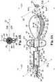
- FIG. 1Aprovides a profile view of a catheter according to an embodiment of the present disclosure.
- FIG. 1Bprovides an end view of the catheter of FIG. 1A as viewed along lines 1 B- 1 B in FIG. 1A .
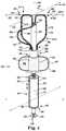
- FIG. 2Aprovides a profile view of a catheter according to an embodiment of the present disclosure.
- FIG. 2Bprovides an end view of the catheter of FIG. 2A as viewed along lines 2 B- 2 B in FIG. 2A .
- FIG. 3illustrates a catheter according to an embodiment of the present disclosure.
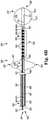
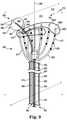
- FIG. 4illustrates a catheter according to an embodiment of the present disclosure.
- FIGS. 5A and 5Billustrate embodiments of a pulmonary artery catheter that can be used with the catheters according to the present disclosure.
- FIG. 6Aillustrates a catheter according to an embodiment of the present disclosure.
- FIG. 6Billustrates a catheter according to an embodiment of the present disclosure.
- FIG. 6Cillustrates the catheter provided in FIG. 6A positioned within the main pulmonary artery.
- FIG. 6Dillustrates the catheter provided in FIG. 6B positioned within the main pulmonary artery.
- FIG. 7illustrates a catheter according to an embodiment of the present disclosure.
- FIG. 8illustrates a catheter according to an embodiment of the present disclosure.
- FIG. 9illustrates a catheter system according to an embodiment of the present disclosure.
- FIG. 10provides an illustration of a main pulmonary artery of a heart.
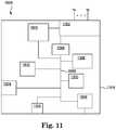
- FIG. 11provides an illustration of a stimulation system for use with the catheter or catheter system of the present system.
- Embodiments of the present disclosureprovide for a catheter and a catheter system for use in electrical neuromodulation.
- the catheter and the catheter system of the present disclosuremay be useful in electrical neuromodulation of patients with cardiac disease, such as patients with acute and/or chronic cardiac disease.
- the configuration of the catheter and the catheter system of the present disclosureallows for a portion of the catheter to be positioned within the vasculature of the patient in the main pulmonary artery and/or one or both of the pulmonary arteries (the right pulmonary artery and the left pulmonary artery). Once positioned, the catheter and the catheter system of the present disclosure can provide electrical energy to stimulate the autonomic nerve fibers surrounding the main pulmonary artery and/or one or both of the pulmonary arteries in an effort to provide adjuvant cardiac therapy to the patient.
- distal and proximalare used in the following description with respect to a position or direction relative to the treating clinician. “Distal” or “distally” are a position distant from or in a direction away from the clinician. “Proximal” and “proximally” are a position near or in a direction toward the clinician.
- FIGS. 1A and 1Bthere is shown a catheter 100 according to the present disclosure.
- FIG. 1Ashows a side view of the catheter 100
- FIG. 1Bshows an end view of the catheter 100 taken along view lines 1 B- 1 B as seen in FIG. 1A .
- the catheter 100includes an elongate body 102 having a first end 104 and a second end 106 distal from the first end 104 .
- the elongate body 102includes an elongate radial axis 108 that extends through the first end 104 and the second end 106 of the elongate body 102 .
- a first plane 110extends through the elongate radial axis 108 over the length of the elongate body 102 .
- a planeis an imaginary flat surface on which a straight line joining any two points on it would wholly lie and is used herein to help orientate the relative position of structures on the catheter 100 .
- the first plane 110is used herein, among other reasons, to help provide the relative position of electrodes that are located on the embodiments of the catheters provided herein.
- Catheter 100further includes at least two elongate stimulation members 114 (as illustrated in FIGS. 1, 114-1 and 114-2 ).
- the stimulation members 114extend from the elongate body 102 , where each of the at least two elongate stimulation members 114 - 1 and 114 - 2 curves into a first volume 116 defined at least in part by the first plane 110 .
- the at least two elongate stimulation members 114extend from approximately the second end 106 of the elongate body 102 into the first volume 116 .
- FIG. 1also illustrates at least one electrode 118 on each of the at least two elongate stimulation members 114 .
- the at least one electrode 118 on each of the elongate stimulation members 114form an electrode array in the first volume 116 defined at least in part by the first plane 110 .
- the at least one electrode 118 on each of the stimulation members 114are electrically isolated from one another, where the stimulation members 114 are each formed of an electrically insulating material as discussed herein.
- Each of the at least one electrode 118is coupled to a corresponding conductive element 120 .
- the conductive elements 120are electrically isolated from each other and extend through the stimulation members 114 from each respective electrode 118 through the first end 104 of the elongate body 102 .
- the conductive elements 120terminate at a connector port, where each of the conductive elements 120 can be releasably coupled to a stimulation system, as discussed herein. It is also possible that the conductive elements 120 are permanently coupled to the stimulation system (e.g., not releasably coupled).
- the stimulation systemcan be used to provide stimulation electrical energy that is conducted through the conductive elements 120 and delivered across combinations of the electrodes 118 in the electrode array.
- Each of the at least two elongate stimulation members 114includes a stimulation member elongate body 122 having a distal end 124 . As illustrated, the distal end 124 of the stimulation member elongate body 122 for each of the elongate stimulation members 114 extends from the elongate body 102 .
- Each of the elongate body 102 and the stimulation member elongate body 122include a surface defining a lumen 128 through which a wire 126 passes.
- the wire 126is joined to its respective stimulation member elongate body 122 at or near the distal end 124 , where the wire 126 then freely extends through the lumen 128 in the elongate stimulation member 114 past the first end 104 of the elongate body 102 .
- the lumen 128has a diameter that is large enough to allow the wire 126 to be moved longitudinally within the lumen 128 .
- the portion of the wire 126 extending from the first end 104can be used to apply pressure against the stimulation member elongate body 122 at or near the distal end 124 , where the wire 126 under such pressure can deflect, or bend, thereby imparting the curve into each of the at least two elongate stimulation members 114 into the first volume 116 defined at least in part by the first plane 110 .
- the at least two elongate stimulation members 114extend radially away from the elongate body 102 over a range of distances depending upon how much pressure is applied to the wires 126 .
- the curves of the at least two elongate stimulation members 114can have a radius of curvature that changes along the length of the stimulation member elongate body 122 .
- the at least two elongate stimulation members 114curve only in the first volume 116 defined at least in part by the first plane 110 .
- FIGS. 1A and 1Balso illustrate a second volume 130 defined at least in part by the first plane 110 (being opposite the first volume 116 ) that contains no electrodes.
- FIGS. 1A and 1Balso illustrate an embodiment in which the at least two elongate stimulation members 114 include a first elongate stimulation member 114 - 1 and a second elongate stimulation member 114 - 2 . In addition to the first elongate stimulation member 114 - 1 and the second elongate stimulation member 114 - 2 , FIGS.
- FIG. 1A and 1Bshow a second plane 112 perpendicularly intersecting the first plane 110 along the elongate radial axis 108 of the elongate body 102 .
- the first plane 110 and the second plane 112divide the first volume 116 into a first quadrant volume 132 and a second quadrant volume 134 .
- the first elongate stimulation member 114 - 1curves into the first quadrant volume 132
- the second elongate stimulation member 114 - 2curves into the second quadrant volume 134 .
- the catheter 100also includes an anchor member 136 that extends from the elongate body 102 into the second volume 130 defined at least in part by the first plane 110 and opposite the first volume 116 .
- the anchor member 136does not include an electrode.
- the anchor member 136is not occlusive within the vasculature and/or does not encourage thrombosis or coagulation of the blood within the vasculature.
- the anchor member 136 and the elongate body 102include surfaces defining a lumen 199 through which wire 140 passes.
- the wire 140is joined to anchor member 136 at or near a distal end 197 of the member 136 , where the wire 140 freely extends through the lumen 199 of the anchor member 136 past the first end 104 of the elongate body 102 .
- the lumen 199has a diameter that is large enough to allow the wire 140 to be moved longitudinally within the lumen 199 .
- the portion of the wire 140 extending from the first end 104can be used to apply pressure against the anchor member 136 at or near its distal end 197 , where the wire 140 under such pressure can deflect, or bend, thereby imparting the curve into the anchor member 136 .
- the anchor member 136can extend radially away from the elongate body 102 over a range of distances depending upon how much pressure is applied to the wire 140 . As discussed herein, the anchor member 136 can be used to bring the electrodes 118 into contact with a vascular lumenal surface (e.g., a posterior surface of the main pulmonary artery and/or one or both of the pulmonary arteries) with a variety of pressures. Optionally, the anchor member 136 can be configured to include one or more of the electrode 118 , as discussed herein.
- Each of the wires 126 and the wire 140upon being used to impart the curves in their respective members, can then be releasably locked in place by preventing the longitudinal movement of the wire relative the elongate body 102 .
- a clamp or other devicecan be used to create contact between the wire and the surface of the lumen sufficient to prevent the wire from moving relative the surface of the lumen. This clamping action can also function as a hemostasis valve to minimize blood loss.
- FIGS. 1A and 1Balso illustrate a pulmonary artery catheter 191 (partially shown to show detail of catheter 100 ) that can be used with catheter 100 to provide for a catheter system.
- the pulmonary artery catheter 191includes an elongate catheter body 1100 with a first end 1102 , a second end 1104 , a peripheral surface 1106 and an interior surface 1108 , opposite the peripheral surface 1106 .
- the interior surface 1108defines a lumen 1110 that extends between the first end 1102 and the second end 1104 of the elongate catheter body 1100 .
- the lumen 1110is of a sufficient size and shape to house at least a portion of the catheter 100 inside the lumen 1110 during delivery of the catheter.
- the anchor member 136 and the at least two elongate stimulation members 114 , along with a least a portion of the elongate body 102 ,can be positioned within the lumen 1110 .
- the anchor member 136 , the at least two elongate stimulation members 114 and at least a portion of the elongate body 102can be deployed from the distal end 1104 of the pulmonary artery catheter 191 during the delivery and implantation of the catheter 100 .
- the pulmonary artery catheter 191can further include an inflatable balloon 1112 on the peripheral surface 1106 of the elongate catheter body 1100 .
- the inflatable balloon 1112has a balloon wall 1114 with an interior surface 1116 that along with a portion of the peripheral surface 1106 of the elongate catheter body 1100 defines a fluid tight volume 1118 .
- the pulmonary artery catheter 191further includes an inflation lumen 1120 that extends through the elongate catheter body 1100 , where the inflation lumen 1118 has a first opening 1122 into the fluid tight volume 1116 of the inflatable balloon 1112 and a second opening 1124 proximal to the first opening 1122 to allow for a fluid to move in the fluid tight volume 1118 to inflate and deflate the balloon 1112 .
- a syringe, or other known devices, containing the fluide.g., saline or a gas (e.g., oxygen)
- the fluide.g., saline or a gas (e.g., oxygen)
- FIG. 1Ashows the balloon 1112 in an inflated state
- FIG. 1Bshows the balloon 1112 in a deflated state.
- the catheter system shown in FIG. 1can be used to position the catheter 100 in the main pulmonary artery and/or one or both of the pulmonary arteries of the patient, as described herein.
- the pulmonary artery catheter 191 with the catheter 100 positioned within the lumen 1110is introduced into the vasculature through a percutaneous incision, and guided to the right ventricle using known techniques.
- the catheter 100can be inserted into the vasculature via a peripheral vein of the arm (e.g., as with a peripherally inserted central catheter). Changes in a patient's electrocardiography and/or pressure signals from the vasculature can be used to guide and locate the catheter 100 within the patient's heart.
- the balloon 1112can be inflated, as described, to allow the pulmonary artery catheter 191 and the catheter 100 to be carried by the flow of blood from the right ventricle to the main pulmonary artery and/or one of the pulmonary arteries.
- various imaging modalitiescan be used in positioning the catheter and/or catheter system of the present disclosure in the main pulmonary artery and/or one of the pulmonary arteries of the patient. Such imaging modalities include, but are not limited to, fluoroscopy, ultrasound, electromagnetic, electropotential modalities.
- the catheter systemcan be advance along the main pulmonary artery until the distal end 1104 of the pulmonary artery catheter 191 contacts the top of the main pulmonary artery (e.g., a location distal to the pulmonary valve and adjacent to both the pulmonary arteries). This can be done with the balloon 1112 in the inflated or deflated state. Once the distal end 1104 of the pulmonary artery catheter 191 reaches the top of the main pulmonary artery the elongate catheter body 1100 can be moved relative the catheter 100 so as to deploy the catheter 100 from the lumen 1110 of the pulmonary artery catheter 191 .
- Markingscan be present on the peripheral surface of the catheter body 102 , where the markings start and extend from the first end 104 towards the second end 106 of the catheter 100 .
- the distance between the markingscan be of units (e.g., millimeters, inches, etc.), which can allow the length between the distal end 1104 of the pulmonary artery catheter 191 and the top of the main pulmonary artery to be determined.
- a markingcan also be provided on the peripheral surface of the catheter body 102 that indicates when the distal end 1104 of the pulmonary artery catheter 191 is clear of the anchor member 136 and the elongate stimulation members 114 .
- a positioning gaugecan be used to locate the catheter 100 within the main pulmonary artery, where the positioning gauge will be discussed herein in more detail.
- the ability to measure this distance from the top of the main pulmonary arterymay be helpful in placing the electrodes 118 in a desired location within the main pulmonary artery.
- the elongate body 102can also be used to identify, or map, an optimal position for the electrodes 114 within the vasculature.
- the second end 106 of the elongate body 102can be positioned at the desired distance from the top of the main pulmonary artery using the markings on the peripheral surface of the catheter body 102 .
- Wires 126 and 140are then used to impart the curves into the elongate stimulation members 114 and the anchor member 136 .
- the elongate stimulation members 114 and the anchor member 136can be provided with curves of sufficient size to contact a surface of the main pulmonary artery, such as the anterior surface of the main pulmonary artery, and thereby bring the electrodes 118 into contact with the main pulmonary artery or one of the pulmonary arteries (the left pulmonary artery or the right pulmonary artery).
- the anchor member 136biases and helps to anchor the electrodes 118 along the vessel surface (e.g., along the posterior surface of the main pulmonary artery or one of the pulmonary arteries (the left pulmonary artery or the right pulmonary artery)).
- the anchor member 136can be used to bring the electrodes 118 into contact with the lumenal surface of the main pulmonary artery or one of the pulmonary arteries with a variety of pressures. So, for example, the anchor member 136 can bring the electrodes 118 into contact with the lumenal surface of the main pulmonary artery or one of the pulmonary arteries with a first pressure.
- stimulation electrical energycan be delivered across combinations of two or more of the at least one electrode 118 in the electrode array. It is possible for the patient's cardiac response to the stimulation electrical energy to be monitored and recorded for comparison to other subsequent tests.
- any combination of electrodesincluding reference electrodes (as discussed herein) positioned within or on the patient's body, can be used in providing stimulation to and sensing cardiac signals from the patient.
- the pressurecan be reduced and the elongate body 102 can be rotated in either a clockwise or counter-clockwise direction to reposition the electrodes 118 in contact with the lumenal surface of the main pulmonary artery or one of the pulmonary arteries.
- the stimulation systemcan again be used to deliver stimulation electrical energy across combinations of two or more of the at least one electrode 118 in the electrode array.
- the patient's cardiac response to this subsequent testcan then be monitored and recorded for comparison to previous and subsequent test. In this way, a preferred location for the position of the electrodes 118 along the lumenal surface of the main pulmonary artery or one of the pulmonary arteries can be identified.
- the wire 140can be used to increase the pressure applied by the anchor member 136 , thereby helping to better anchor the catheter 100 in the patient.
- FIGS. 2A and 2Bthere is shown an additional embodiment of catheter 200 .
- FIG. 2Ashows a side view of the catheter 200
- FIG. 2Bshows an end view of the catheter 200 taken along view lines 2 B- 2 B as seen in FIG. 2A .
- Catheter 200includes at least the structures as discussed herein for catheter 100 , a discussion of which is not repeated but the element numbers are included in FIGS. 2A and 2B with the understanding that the discussion of these elements is implicit.
- catheter 200further includes a structure 260 extending between at least two of the least two elongate stimulation members 214 .
- the structure 260is flexible such that it can transition between a delivery or low-profile state (radially folded state) that allows the structure 260 to be delivered into the main pulmonary artery and/or one of the pulmonary arteries, and a deployed or expanded state (radially expanded) as illustrated in FIG. 2A .
- the wires 226 and the least two elongate stimulation members 214can be used to bring the structure 260 into its deployed or expanded state.
- an example of the structure 260is a mesh structure.
- the structure 260has flexible strands that are connected to form a pattern of opening between the strands. Electrodes 262 can be present at one or more of the connections of the strands.
- the strandscan be formed of the same insulative material as the elongate body 202 and the elongate stimulation members 214 . Alternatively, a different insulative material than that used for the elongate body 202 and the elongate stimulation members 214 can be used for the strands of the structure 260 .
- Examples of such insulative material for one or more portions of the catheters and structures provided hereincan include, but are not limited to, medical grade polyurethanes, such as polyester-based polyurethanes, polyether-based polyurethanes, and polycarbonate-based polyurethanes; polyamides, polyamide block copolymers, polyolefins such as polyethylene (e.g., high density polyethylene); and polyimides, among others.
- medical grade polyurethanessuch as polyester-based polyurethanes, polyether-based polyurethanes, and polycarbonate-based polyurethanes
- polyamidespolyamide block copolymers
- polyolefinssuch as polyethylene (e.g., high density polyethylene)
- polyimidesamong others.
- the structure 260can also have a predefined shape that helps to locate and position the at least two of the least two elongate stimulation members 214 and the electrodes 218 thereon. So, for example, the structure 260 can be used to adjust and/or maintain the distance between electrodes 218 on the adjacent stimulation members 214 .
- the structure 260can also include one or more of an additional electrode 262 .
- the additional electrode 262can either be positioned on the structure 260 or formed as an integral part of the structure 260 , where each of the additional electrodes 262 is electrically isolated from each of the other electrodes 262 and/or 218 .
- the additional electrode 262includes a conductive element 264 .
- Each of the conductive elements 264are electrically isolated from each other and extend through the strands of the structure 260 from each respective additional electrode 262 through the stimulation members 214 and the elongate body 202 to the first end 204 .
- the conductive elements 264terminate at a connector port, where each of the conductive elements 220 and 264 can be releasably coupled to the stimulation system, as discussed herein.
- the conductive elements 120are permanently coupled to the stimulation system (e.g., not releasably coupled).
- the stimulation systemcan be used to provide stimulation electrical energy that is conducted through the conductive elements 220 and 264 to combinations of the additional electrode 262 and at least one of the at least one electrode 218 on each of the at least two elongate stimulation members 214 .
- FIG. 2Aalso illustrates an anchor wire 244 extending longitudinally through the stimulation member elongate body 222 .
- the elongate body 202 and the member elongate body 222include a surface defining a lumen having a first opening at the proximal end 204 and a second opening at or adjacent to the distal end 224 of the stimulation member elongate body 222 .
- the anchor wire 244freely passes through the lumen, with a first end 246 extending from the elongate body 222 at the proximal end 204 of the elongate body 202 and a second end 248 having an anchoring structure (e.g., a barb) that extends from the second opening at or adjacent to the distal end 224 of the stimulation member elongate body 222 .
- the anchor wire 244can be advance through the lumen (e.g., longitudinal force can be applied to the first end 246 of the anchor wire 244 ) to extend the anchoring structure away from the stimulation member elongate body 214 .
- the anchor wire 244can also be used to help secure the catheter 200 in the patient at the desired location.
- One or more of the anchor wire and the associated structurescan also be included with the catheter illustrated in FIGS. 1A and 1B .
- the anchor wire 244can be configured and used as an electrode with the stimulation system of the present disclosure.
- FIG. 2also illustrates a pulmonary artery catheter 291 (partially shown to show detail of catheter 200 ), as discussed herein.
- the catheter system shown in FIG. 2can be used to position the catheter 200 in the main pulmonary artery and/or one of the pulmonary arteries of the patient, as described herein.
- the pulmonary artery catheter 291 with the catheter 200 positioned within the lumen 2108is introduced into the vasculature through a percutaneous incision, and guided to the right ventricle using known techniques.
- the balloon 2112is inflated, as described, to allow the pulmonary artery catheter 291 and the catheter 200 to be carried by the flow of blood from the right ventricle to the main pulmonary artery or one of the pulmonary arteries.
- the catheter system shown in FIGS. 2A and 2Billustrates an embodiment of the present disclosure that includes a positioning gauge 252 .
- the positioning gauge 252includes an elongate gauge body 254 with a first end 256 and a bumper end 258 distal to the first end 256 .
- the elongate gauge body 254can be moved longitudinally within a lumen 250 defined by a surface that extends through the elongate body 202 from its first end 204 through the second end 206 .
- the bumper end 258can have a shape with a surface area no less than a surface area of the distal end 206 of the elongate body 202 taken perpendicularly to the elongate radial axis 208 .
- the elongate gauge body 254extends through the first lumen 250 of the elongate body 202 to position the bumper end 258 beyond the second end 206 of the elongate body 202 .
- the first end 256 of the position gauge 252extends from the first end 204 of the elongate body 202 , where the elongate gauge body 254 includes a marking 2200 that indicates a length between the second end 206 of the elongate body 202 and the bumper end 258 of the position gauge 252 .
- the bumper end 258 of the positioning gauge 252is approximately even with the distal end 224 of the stimulation member elongate body 222 , the distal end 297 of the anchor member 236 and the distal end 2104 of the pulmonary artery catheter 291 (e.g., the elongate body 202 , the anchor member 236 and the elongate stimulation members 214 are positioned within the lumen 2110 of the pulmonary artery catheter 291 ).
- the catheter systemcan be advance along the main pulmonary artery until the bumper end 258 of the positioning gauge 252 contacts the top of the main pulmonary artery (e.g., a location distal to the pulmonary valve and adjacent to both the pulmonary arteries). This can be done with the balloon 1112 in the inflated or deflated state.
- the pulmonary artery catheter 291(with the catheter 200 positioned within its lumen 2110 ) can be moved relative the bumper end 258 (e.g., the pulmonary artery catheter 291 and the catheter 200 are moved away from the bumper end 258 ).
- the markings 2200 on the elongate gauge body 254can be used to indicate a length between the distal end 224 of the stimulation member elongate body 222 /the distal end 297 of the anchor member 236 /the distal end 2104 of the pulmonary artery catheter 291 and the bumper end 258 of the position gauge 252 .
- distance between the markings 2200can be of units (e.g., millimeters, inches, etc.), which can allow the length from the between the distal end 224 of the stimulation member elongate body 222 /the distal end 297 of the anchor member 236 /the distal end 2104 of the pulmonary artery catheter 291 to be determined.
- the pulmonary artery catheter 291can be moved relative the catheter 200 so as to deploy the anchor member 236 and the elongate stimulation members 214 with the electrodes 218 within the main pulmonary artery or one of the pulmonary arteries.
- the ability to measure this distance from the top of the main pulmonary arterymay be helpful in placing the electrodes 218 in a desired location within the main pulmonary artery or one of the pulmonary arteries.
- the distal end 224 of the stimulation member elongate body 222 and the distal end 297 of the anchor member 236can be positioned at the desired distance from the top of the main pulmonary artery using the markings on the peripheral surface of the positioning gauge 252 .
- Wires 226 and 240can be used to impart the curves into the elongate stimulation members 214 and the anchor member 236 .
- the elongate stimulation members 214 and the anchor member 236can be provided with curves of sufficient size to contact the anterior surface of the main pulmonary artery and thereby bring the electrodes 218 into contact with the lumenal surface of the main pulmonary artery.
- the anchor member 236biases and helps to anchor the electrodes 218 along the vessel surface (e.g., along the posterior surface of the main pulmonary artery).
- the anchor member 236can be configured to include one or more of the electrode 218 as discussed herein.
- the anchor member 236can be used to bring the electrodes 218 into contact with the lumenal surface of the main pulmonary artery or one of the pulmonary arteries with a variety of pressures. So, for example, the anchor member 236 can bring the electrodes 218 into contact with the lumenal surface of the main pulmonary artery or one of the pulmonary arteries with a first pressure.
- stimulation electrical energy from the stimulation systemas discussed herein, of electrical energy can be delivered across combinations of two or more of the electrodes 218 in the electrode array. The patient's cardiac response to the stimulation electrical energy can then be monitored and recorded for comparison to other subsequent tests.
- the pressurecan be reduced and the elongate body 202 can then be rotated in either a clockwise or counter-clockwise direction and/or lengthwise relative the top of the main pulmonary artery or one of the pulmonary arteries to reposition the electrodes 218 in contact with the lumenal surface of the main pulmonary artery or one of the pulmonary arteries.
- the stimulation systemcan again be used to deliver stimulation electrical energy across combinations of two or more of the electrodes 218 in the electrode array.
- the patient's cardiac response to this subsequent testcan then be monitored and recorded for comparison to previous and subsequent test. In this way, a preferred location for the position of the electrodes 218 along the lumenal surface of the main pulmonary artery or one of the pulmonary arteries can be identified.
- the wire 240can be used to increase the pressure applied by the anchor member 236 , thereby helping to better anchor the catheter 200 in the patient.
- catheter 300where catheter 300 includes the structures as discussed herein for catheters 100 and 200 .
- catheter 300includes an elongate body 302 having a first end 304 and a second end 306 distal from the first end 304 .
- the elongate body 302includes an elongate radial axis 308 that extends through the first end 304 and the second end 306 of the elongate body 302 .
- a first plane 310extends through the elongate radial axis 308 over the length of the elongate body 302 .
- Catheter 300further includes at least two elongate stimulation members 314 , as discussed herein, that extend from the elongate body 302 .
- Each of the at least two elongate stimulation members 314 - 1 and 314 - 2curves into a first volume 316 defined at least in part by the first plane 310 .
- the at least two elongate stimulation members 314extend from approximately the second end 306 of the elongate body 302 into the first volume 316 .
- FIG. 3also illustrates at least one electrode 318 on each of the at least two elongate stimulation members 314 .
- the electrodes 318 on the elongate stimulation members 314form an electrode array on the first volume 316 .
- the catheter 300also includes conductive elements 320 that extend through each of the elongate stimulation members 314 . As discussed herein, the conductive elements 320 can conduct electrical current to combinations of two or more of the electrodes 318 .
- Each of the at least two elongate stimulation members 314includes a stimulation member elongate body 322 each having a distal end 324 that can move relative each other. In other words, the distal end 324 of each of the stimulation member elongate body 322 is free of each other. As illustrated in FIG. 3 , the at least two elongate stimulation members 314 curve only in the first volume 316 defined at least in part by the first plane 310 . FIG. 3 also illustrates a second volume 330 defined at least in part by the first plane 310 (being opposite the first volume 316 ) that contains no electrodes. FIG.
- the catheter 300also illustrate an embodiment in which the at least two elongate stimulation members 314 include a first elongate stimulation member 314 - 1 and a second elongate stimulation member 314 - 2 , where the first elongate stimulation member 314 - 1 curves into the first quadrant volume 332 and the second elongate stimulation member 314 - 2 curves into the second quadrant volume 334 , as previously discussed herein.
- the catheter 300also includes an anchor member 336 that extends from the elongate body 302 into the second volume 330 . As illustrated, the anchor member 336 does not include an electrode.
- the anchor member 336includes an elongate body 338 as previously discussed.
- the anchor member 336can be configured to include one or more of the electrode 318 as discussed herein.
- Each of the at least two elongate stimulation members 314 and the anchor member 336can also include a wire 366 extending longitudinally through the stimulation member elongate body 322 and the elongate body 338 , respectively.
- the wire 366can provide each of the at least two elongate stimulation members 314 and the anchor member 336 with a predefined shape.
- the wire 366 in each of the at least two elongate stimulation members 314 and the anchor member 336can have a coil or helical configuration that imparts a curve to the stimulation member elongate body 322 and the elongate body 338 , respectively.
- the wire 366can also impart stiffness to the stimulation member elongate body 322 that is sufficient to maintain the predefined shape under the conditions within the vasculature of the patient. So, for example, the wire 366 provides sufficient stiffness and flexibility to the stimulation member elongate body 322 to elastically return the least two elongate stimulation members 314 to their curved configuration when placed in the vasculature of a patient.
- the wire 366can be formed of a variety of metals or metal alloys.
- metals or metal alloysinclude surgical grade stainless steel, such as austenitic 316 stainless among others, and the nickel and titanium alloy known as Nitinol.
- Other metals and/or metal alloys, as are known,can be used.
- the at least two elongate stimulation members 314can also include an anchor wire 344 , as discussed herein, extending longitudinally through a lumen in the stimulation member elongate body 322 and the elongate body 302 .
- the anchor wire 344includes a first end 346 extending from the elongate body 302 and a second end 348 having an anchoring structure (e.g., a barb).
- the anchor wire 344can be advance through the lumen (e.g, longitudinal force can be applied to the first end 346 of the anchor wire 344 ) to extend the anchoring structure away from the stimulation member elongate body 314 .
- the anchor wire 344can also be used to help secure the catheter 300 in the patient at the desired location.
- the anchor wire 344can be configured and used as an electrode with the stimulation system of the present disclosure.
- the catheter 300further includes a pulmonary artery catheter 391 , as discussed herein.
- the pulmonary artery catheter 391(partially shown to show detail of catheter 300 ) that can be used with catheter 300 to provide for a catheter system.
- the pulmonary artery catheter 391includes an elongate catheter body 3100 with a first end 3102 , a second end 3104 , a peripheral surface 3106 and an interior surface 3108 , opposite the peripheral surface 3106 .
- the interior surface 3108defines a lumen 3110 that extends between the first end 3102 and the second end 3104 of the elongate catheter body 3100 .
- the lumen 3110is of a sufficient size and shape to house at least a portion of the catheter 300 inside the lumen 3110 during delivery of the catheter.
- the anchor member 336 and the at least two elongate stimulation members 314 , along with a least a portion of the elongate body 302 ,can be positioned within the lumen 3110 .
- the anchor member 336 , the at least two elongate stimulation members 314 and at least a portion of the elongate body 302can be deployed from the distal end 3104 of the pulmonary artery catheter 391 during the delivery and implantation of the catheter 300 .
- the pulmonary artery catheter 391can further include an inflatable balloon 3112 on the peripheral surface 3106 of the elongate catheter body 3100 .
- the inflatable balloon 3112has a balloon wall 3114 with an interior surface 3116 that along with a portion of the peripheral surface 3106 of the elongate catheter body 3100 defines a fluid tight volume 3118 .
- the pulmonary artery catheter 391further includes an inflation lumen 3120 that extends through the elongate catheter body 3100 , where the inflation lumen 3118 has a first opening 3122 into the fluid tight volume 3116 of the inflatable balloon 1112 and a second opening 3124 proximal to the first opening 3122 to allow for a fluid to move in the fluid tight volume 3118 to inflate and deflate the balloon 3112 , as discussed herein.
- the catheter system shown in FIG. 3can be used to position the catheter 300 in the main pulmonary artery and/or one or both of the pulmonary arteries of the patient, as described herein.
- the at least two elongate stimulation members 314 and the anchor member 336can be repositioned within the lumen 3110 of the pulmonary artery catheter 391 by moving the elongate catheter body 3100 relative the elongate body 302 back over the at least two elongate stimulation members 314 and the anchor member 336 .
- the catheter system illustrated in FIG. 3can optionally include the positioning gauge, as discussed herein.
- the electrodecan have a variety of configurations and sizes.
- the electrodes discussed hereincan be ring-electrodes that fully encircle the body on which they are located.
- the electrodes discussed hereincan also be a partial ring, where the electrode only partially encircles the body on which they are located.
- the electrodescan be partial ring electrodes that preferably only contact the lumenal surface of the main pulmonary artery and/or pulmonary arteries, as discussed herein. This configuration may help to localize the stimulation electrical energy, as discussed herein, into the vascular and adjacent tissue structures (e.g., autonomic fibers) and away from the blood.
- the electrodes and conductive elements provided hereincan be formed of a conductive biocompatible metal or metal alloy.
- conductive biocompatible metal or metal alloysinclude, but are not limited to, titanium, platinum or alloys thereof.
- Other biocompatible metal or metal alloysare known.
- catheter 400includes an elongate body 402 having a first end 404 and a second end 406 distal from the first end 404 .
- the elongate body 402includes an elongate radial axis 408 that extends through the first end 404 and the second end 406 of the elongate body 402 .
- a first plane 410extends through the elongate radial axis 408 over the length of the elongate body 402 .
- Catheter 400further includes at least two elongate stimulation members 414 , as discussed herein, that extend from the elongate body 402 .
- Each of the at least two elongate stimulation members 414 - 1 and 414 - 2curves into a first volume 416 defined at least in part by the first plane 410 .
- the at least two elongate stimulation members 414extend from approximately the second end 406 of the elongate body 402 into the first volume 416 .
- FIG. 4also illustrates at least one electrode 418 on each of the at least two elongate stimulation members 414 .
- the electrodes 418 on the elongate stimulation members 414form an electrode array on the first volume 416 .
- the catheter 400also includes conductive elements 420 that extend through each of the elongate stimulation members 414 . As discussed herein, the conductive elements 420 can conduct electrical current to combinations of two or more of the electrodes 418 .
- Each of the at least two elongate stimulation members 414includes a stimulation member elongate body 422 each having a distal end 424 that extends from the elongate body 402 . As illustrated in FIG. 4 , the at least two elongate stimulation members 414 curve only in the first volume 416 defined at least in part by the first plane 410 . FIG. 4 also illustrates a second volume 430 defined at least in part by the first plane 410 (being opposite the first volume 416 ) that contains no electrodes. FIG.
- the catheter 400also includes an anchor member 436 that extends from the elongate body 402 into the second volume 430 . As illustrated, the anchor member 436 does not include an electrode.
- the anchor member 436includes an elongate body 438 as previously discussed.
- the anchor member 436can be configured to include one or more of the electrode 418 as discussed herein.
- Each of the at least two elongate stimulation members 414 and the anchor member 436can also include a wire 466 extending longitudinally through the stimulation member elongate body 422 and the elongate body 438 , respectively.
- the wire 466can provide each of the at least two elongate stimulation members 414 and the anchor member 436 with a predefined shape.
- the wire 466 in each of the at least two elongate stimulation members 414 and the anchor member 436can have a coil or helical configuration that imparts a curve to the stimulation member elongate body 422 and the elongate body 438 , respectively.
- the wire 466can also impart stiffness to the stimulation member elongate body 422 that is sufficient to maintain the predefined shape under the conditions within the vasculature of the patient. So, for example, the wire 466 provides sufficient stiffness and flexibility to the stimulation member elongate body 422 to elastically return the least two elongate stimulation members 414 to their curved configuration when placed in the vasculature of a patient.
- the wire 466can be formed of a variety of metals or metal alloys as discussed herein.
- the at least two elongate stimulation members 414can also include an anchor wire 444 extending longitudinally through the stimulation member elongate body 422 .
- the anchor wire 444includes a first end 446 extending from the elongate body 402 and a second end 448 having an anchoring structure (e.g., a barb). Longitudinal force applied to the first end 446 of the anchor wire 444 advances the anchor wire 444 through the stimulation member elongate body 414 to extend the anchoring structure away from the stimulation member elongate body 414 .
- the anchor wire 444can be configured and used as an electrode with the stimulation system of the present disclosure.
- the catheter 400further includes a pulmonary artery catheter 491 , as discussed herein.
- the pulmonary artery catheter 491(partially shown to show detail of catheter 400 ) that can be used with catheter 400 to provide for a catheter system.
- the pulmonary artery catheter 491includes an elongate catheter body 4100 with a first end 4102 , a second end 4104 , a peripheral surface 4106 and an interior surface 4108 , opposite the peripheral surface 4106 .
- the interior surface 4108defines a lumen 4110 that extends between the first end 4102 and the second end 4104 of the elongate catheter body 4100 .
- the lumen 4110is of a sufficient size and shape to house at least a portion of the catheter 400 inside the lumen 4110 during delivery of the catheter.
- the anchor member 436 and the at least two elongate stimulation members 414 , along with a least a portion of the elongate body 402 ,can be positioned within the lumen 4110 .
- the anchor member 436 , the at least two elongate stimulation members 414 and at least a portion of the elongate body 402can be deployed from the distal end 4104 of the pulmonary artery catheter 491 during the delivery and implantation of the catheter 400 .
- the pulmonary artery catheter 491can further include an inflatable balloon 4112 on the peripheral surface 4106 of the elongate catheter body 4100 .
- the inflatable balloon 4112has a balloon wall 4114 with an interior surface 4116 that along with a portion of the peripheral surface 4106 of the elongate catheter body 4100 defines a fluid tight volume 4118 .
- the pulmonary artery catheter 491further includes an inflation lumen 4120 that extends through the elongate catheter body 4100 , where the inflation lumen 4118 has a first opening 4122 into the fluid tight volume 4116 of the inflatable balloon 1112 and a second opening 4124 proximal to the first opening 4122 to allow for a fluid to move in the fluid tight volume 4118 to inflate and deflate the balloon 4112 , as discussed herein.
- the catheter system shown in FIG. 4can be used to position the catheter 400 in the main pulmonary artery and/or one or both of the pulmonary arteries of the patient, as described herein.
- the at least two elongate stimulation members 414 and the anchor member 436can be repositioned within the lumen 4110 of the pulmonary artery catheter 491 by moving the elongate catheter body 4100 relative the elongate body 402 back over the at least two elongate stimulation members 414 and the anchor member 436 .
- the catheter system illustrated in FIG. 4can optionally include the positioning gauge, as discussed herein.
- the pulmonary artery catheter 591includes an elongate catheter body 5100 with a first end 5102 , a second end 5104 , a peripheral surface 5106 and an interior surface 5108 , opposite the peripheral surface 5106 .
- the interior surface 5108defines a lumen 5110 that extends between the first end 5102 and the second end 5104 of the elongate catheter body 5100 .
- the lumen 5110is of a sufficient size and shape to house at least a portion of the catheter 100 , 200 , 300 or 400 inside the lumen 5110 during delivery of the catheter.
- the anchor member and the at least two elongate stimulation members, along with a least a portion of the elongate body,can be positioned within the lumen 5110 .
- the anchor member, the at least two elongate stimulation members and at least a portion of the elongate bodycan be deployed from the distal end 5104 of the pulmonary artery catheter 591 during the delivery and implantation of the catheter 100 , 200 , 300 or 400 .
- the pulmonary artery catheter 591includes an inflatable balloon 5112 .
- the inflatable balloon 5112is positioned on an elongate inflation catheter body 5300 that passes through a balloon lumen 5302 .
- the balloon lumen 5302is defined by lumen surface 5304 that can extend from the first end 5102 through the second end 5104 of the elongate catheter body 5100 .
- the balloon lumen 5302has a cross-sectional dimension that allows the elongate inflation catheter body 5300 to longitudinally move within the balloon lumen 5302 . As such, the inflatable balloon 5112 can be moved relative the distal end 5104 of the pulmonary artery catheter 591 .
- the inflatable balloon 5112has a balloon wall 5114 with an interior surface 5116 that along with a portion of a peripheral surface 5106 of the elongate inflation catheter body 5300 defines a fluid tight volume 5118 .
- the elongate inflation catheter body 5300further includes an inflation lumen 5120 that extends through the elongate inflation catheter body 5300 , where the inflation lumen 5118 has a first opening 5122 into the fluid tight volume 5116 of the inflatable balloon 5112 and a second opening 5124 proximal to the first opening 5122 to allow for a fluid to move in the fluid tight volume 5118 to inflate and deflate the balloon 5112 .
- a syringe, or other known devices, containing the fluid (e.g., saline or a gas (e.g., oxygen))can be used to inflate and deflate the balloon 5112 .
- the cross-sectional dimension of the balloon lumen 5302is also sufficient to allow the inflatable balloon 5112 in its fully deflated state to be housed within the lumen 5302 .
- the inflatable balloon 5112 along with at least a portion of the elongate inflation catheter body 5300can be extended from the second end 5104 when the inflatable balloon 5112 is to be inflated.
- FIG. 5Billustrates an alternative embodiment of the pulmonary artery catheter 591 that can be used with the catheter 100 , 200 , 300 or 400 according to the present disclosure.
- the pulmonary artery catheter 591includes the elongate catheter body 5100 with the first end 5102 , the second end 5104 , the peripheral surface 5106 and the interior surface 5108 , opposite the peripheral surface 5106 .
- the interior surface 5108defines the lumen 5110 that extends between the first end 5102 and the second end 5104 of the elongate catheter body 5100 .
- the lumen 5110is of a sufficient size and shape to house at least a portion of the catheter 100 , 200 , 300 or 400 inside the lumen 5110 during delivery of the catheter.
- the anchor member and the at least two elongate stimulation members, along with a least a portion of the elongate body,can be positioned within the lumen 5110 (the embodiment illustrated in FIG. 5B has the catheter 100 , 200 , 300 or 400 fully inside the lumen 5110 ).
- the anchor member, the at least two elongate stimulation members and at least a portion of the elongate bodycan be deployed from the distal end 5104 of the pulmonary artery catheter 591 during the delivery and implantation of the catheter 100 , 200 , 300 or 400 .
- the pulmonary artery catheter 591 illustrated in FIG. 5Balso includes two of the inflatable balloons 5112 (shown as 5112 - 1 and 5112 - 2 in FIG. 5B ). As illustrated, each of the inflatable balloons 5112 - 1 and 5112 - 2 are positioned on separate elongate inflation catheter bodies 5300 - 1 and 5300 - 2 , where each of the elongate inflation catheter bodies 5300 - 1 and 5300 - 2 pass through a balloon lumen 5302 - 1 and 5302 - 2 , respectively.
- each balloon lumen 5302 - 1 and 5302 - 2is defined by a lumen surface 5304 - 1 and 5304 - 2 , respectively, which can extend from the first end 5102 through the second end 5104 of the elongate catheter body 5100 .
- the balloon lumen 5302 - 1 and 5302 - 2each have a cross-sectional dimension that allows the elongate inflation catheter body 5300 - 1 and 5300 - 2 to longitudinally move within their respective balloon lumen 5302 - 1 and 5302 - 2 .
- each of the inflatable balloons 5112 - 1 and/or 5112 - 2can be independently moved relative the distal end 5104 of the pulmonary artery catheter 591 .
- each balloon lumen 5302 - 1 and 5302 - 2is sufficient to allow each respective inflatable balloon 5112 - 1 and 5112 - 2 in its fully deflated state to be housed within each respective lumen 5302 - 1 and 5302 - 2 .
- Each inflatable balloon 5112 - 1 and 5112 - 2 along with at least a portion of the elongate inflation catheter body 5300 - 1 and 5300 - 2can independently be extended from the second end 5104 when the inflatable balloon 5112 - 1 and/or 5112 - 2 is to be inflated.
- Each of the inflatable balloons 5112 - 1 and 5112 - 2has a balloon wall 5114 - 1 and 5114 - 2 with an interior surface 5116 - 1 and 5116 - 2 , respectively, which along with a portion of a peripheral surface 5106 of the elongate inflation catheter body 5300 - 1 and 5300 - 2 define a fluid tight volume 5118 - 1 and 5118 - 2 , respectively.
- the elongate inflation catheter body 5300further includes an inflation lumen 5120 - 1 and 5120 - 2 that extends through the elongate inflation catheter body 5300 - 1 and 5300 - 2 , respectively, where the inflation lumen 5118 - 1 has a first opening 5122 into the fluid tight volume 5116 - 1 , 5116 - 2 of the inflatable balloon 5112 - 1 and 5112 - 2 and a second opening 5124 - 1 and 5124 - 2 proximal to the first opening 5122 - 1 and 5122 - 2 to allow for a fluid to move in the fluid tight volume 5118 - 1 and 5118 - 2 to inflate and deflate the balloon 5112 - 1 and 5112 - 2 .
- Each of the inflatable balloons 5112 - 1 and 5112 - 2can be independently moved relative the second end 5104 of the elongate body 5100 as well as independently inflated, as discussed herein.
- the pulmonary artery catheter 591further includes a positioning gauge 552 .
- the positioning gauge 552includes an elongate gauge body 554 with a first end 556 and a bumper end 558 distal to the first end 556 .
- the elongate gauge body 554can be moved longitudinally within a lumen 550 defined by a surface that extends through the elongate catheter body 5100 .
- the elongate gauge body 554extends through the first lumen 550 of the elongate catheter body 5100 to position the bumper end 558 beyond the second end 5104 of the elongate catheter body 5100 .
- the first end 556 of the position gauge 552extends from the first end 5102 of the elongate catheter body 5100 , where the elongate gauge body 554 includes a marking 5200 that indicates a length between the second end 5104 of the elongate catheter body 5100 and the bumper end 558 of the position gauge 552 .
- the pulmonary artery catheter 591can also include a first anchor 529 that extends laterally from the peripheral surface 5106 of the elongate catheter body 5100 .
- the first anchor 529has struts 531 that form an open framework.
- the struts 531have a peripheral surface 533 having a largest outer dimension that allows the first anchor 529 when deployed to engage a surface of the main pulmonary artery and/or one or both of the pulmonary arteries.
- a sheathcan cover and hold the first anchor 529 in an undeployed state as the pulmonary artery catheter 591 and the catheter 100 , 200 , 300 , 400 are being introduced into the patient.
- the catheter system shown in FIGS. 5A and 5Bcan be used to position the catheter 100 , 200 , 300 and/or 400 in the main pulmonary artery and/or one or both of the pulmonary arteries of the patient, as described herein.
- the pulmonary artery catheter 591 with the catheter positioned within the lumen 5110is introduced into the vasculature through a percutaneous incision, and guided to the right ventricle using known techniques.
- the balloon 5112is inflated, as described, to allow the pulmonary artery catheter 191 and the catheter 100 to be carried by the flow of blood from the right ventricle to the main pulmonary artery or one of the pulmonary arteries.
- the sheathcan be retracted, allowing the first anchor 529 to deploy within the main pulmonary artery.
- the first anchor 529can be brought back into its undeployed state by positioning the sheath (advancing the sheath) back over the first anchor 529 .
- the positioning gauge 552can be used to determine a length between the second end 5104 of the elongate catheter body 5100 and the top of the main pulmonary artery (e.g., a location distal to the pulmonary valve and adjacent to both the pulmonary arteries). Knowing this length, the catheter 100 , 200 , 300 , 400 can be advanced from the lumen 5110 of the elongate catheter body 5100 to a location between the second end 5104 of the elongate catheter body 5100 and the top of the main pulmonary artery.
- This locationcan be determined using markings (e.g., markings providing a length in, for example, millimeters) on a portion of the elongate body of the catheter 100 , 200 , 300 , 400 that extends proximally from the first end 5102 of the elongate catheter body 5100 .
- markingse.g., markings providing a length in, for example, millimeters
- FIGS. 6A through 6Dthere is shown an additional embodiment of a catheter 600 according to the present disclosure.
- the catheter 600includes an elongate catheter body 601 having a first end 603 and a second end 605 .
- the elongate catheter body 601also includes a peripheral surface 607 and an interior surface 609 defining an inflation lumen 611 (shown with a broken line) that extends at least partially between the first end 603 and the second end 605 of the elongate catheter body 601 .
- the catheter 600includes an inflatable balloon 613 on the peripheral surface 607 of the elongate catheter body 601 .
- the inflatable balloon 613includes a balloon wall 615 with an interior surface 617 that along with a portion of the peripheral surface 607 of the elongate catheter body 601 defines a fluid tight volume 619 .
- the inflation lumen 611has a first opening 621 into the fluid tight volume 619 of the inflatable balloon 613 and a second opening 623 proximal to the first opening 621 to allow for a fluid to move in the volume 619 to inflate and deflate the balloon 613 .
- the catheter 600further includes a plurality of electrodes 625 positioned along the peripheral surface 607 of the elongate catheter body 601 .
- the plurality of electrodes 625are located between the inflatable balloon 613 and the first end 603 of the elongate catheter body 601 .
- Conductive elements 627extend through the elongate catheter body 601 , where the conductive elements 627 conduct electrical current to combinations of two or more of the at least one electrode of the plurality of electrodes 625 .
- the catheter 600further includes a first anchor 629 that extends laterally from the peripheral surface 607 of the elongate body 601 , the first anchor 629 having struts 631 forming an open framework.
- the struts 631have a peripheral surface 633 having a largest outer dimension greater than the largest outer dimension of the inflatable balloon 613 (e.g., its largest diameter).
- the first anchor 629has a center point 635 relative the peripheral surface 633 that is eccentric relative a center point 637 of the elongate catheter body 601 relative the peripheral surface 607 .
- FIGS. 6A and 6Bboth show the first anchor 629 .
- FIG. 6Ashows the first anchor 629 positioned between the inflatable balloon 613 and the plurality of electrodes 625 positioned along the peripheral surface 607 of the elongate catheter body 601 .
- FIG. 6Bshows the first anchor 629 positioned between the plurality of electrodes 625 positioned along the peripheral surface 607 of the elongate catheter body 601 and the first end 603 of the elongate catheter body 601 .
- a portion 639 of the elongate catheter body 601 that includes the plurality of electrodes 625curves in a predefined radial direction when placed under longitudinal compression.
- the elongate catheter body 601can be pre-stressed and/or the wall can have thicknesses that allow for the elongate catheter body 601 to curve in the predefined radial direction when placed under longitudinal compression.
- structuressuch as coils or a helix of wire having different turns per unit length can be located within the elongate catheter body 601 in the portion 639 .
- first anchor 629can be deployed in the vasculature of the patient (e.g., in the pulmonary artery), where the first anchor 629 provides a location or point of resistance against the longitudinal movement of the elongate body 601 . As such, this allows a compressive force to be generated in the elongate catheter body 601 sufficient to cause the portion 639 of the elongate catheter body 601 along which the plurality of electrodes 625 are present to curve in the predefined radial direction.
- FIG. 6Cprovides an illustration of the portion 639 of the elongate catheter body 601 curved in a predefined radial direction when placed under longitudinal compression.
- the catheter 600 illustrated in FIG. 6Cis shown in FIG. 6A and is described herein. As illustrated, the catheter 600 has been at least partially positioned within the main pulmonary artery 6500 of a patient's heart (the catheter 600 can also be at least partially positioned within the right pulmonary artery as illustrated), where the balloon 613 and the first anchor 629 are located in the lumen of the left pulmonary artery 6502 .
- a compressive force applied to the elongate catheter body 601can cause the portion 639 of the elongate catheter body 601 along which the plurality of electrodes 625 to curve in the predefined radial direction.
- the plurality of electrodes 625are brought into position and/or contact with the lumenal surface of the main pulmonary artery.
- Providing a rotational torque at the first end 603 of the elongate catheter body 601can help to move the plurality of electrodes 625 relative the lumenal surface. This allows the professional to “sweep” the plurality of electrodes 625 into different positions along the lumenal surface of the main pulmonary artery. As discussed herein, this allows for the patient's cardiac response to the stimulation electrical energy to be monitored and recorded at a variety of locations along the lumenal surface of the pulmonary artery. In this way, a preferred location for the position of the electrodes 625 along the lumenal surface of the main pulmonary artery can be identified.
- the elongate catheter body 601can include a second interior surface 641 defining a shaping lumen 643 that extends from the first end 603 towards the second end 605 .
- the catheter 600 of FIG. 6Bcan also include a shaping wire 645 having a first end 647 and a second end 649 .
- the shaping lumen 643has a size (e.g., a diameter) sufficient to allow the shaping wire 645 to pass through the shaping lumen 643 with the first end 647 of the shaping wire 645 proximal to the first end 603 of the elongate catheter body 601 and the second end 649 of the shaping wire 645 joined to the elongate catheter body 601 so that the shaping wire 645 imparts a curve into the portion 639 of the elongate catheter body 601 having the plurality of electrodes 625 when tension is applied to the shaping wire 645 .
- FIG. 6Dprovides an illustration of the portion 639 of the elongate catheter body 601 curved in a predefined radial direction when using the shaping lumen and shaping wire as discussed herein (the catheter 600 illustrated in FIG. 6D is shown in FIG. 6B and is described herein).
- the catheter 600has been at least partially positioned within the main pulmonary artery 6500 of a patient's heart, where the balloon 613 is located in the lumen of the left pulmonary artery 6502 and the first anchor 629 is located in the main pulmonary artery 6504 . From this position, the shaping wire can be used to impart the curve into the portion 639 of the elongate catheter body 601 having the plurality of electrodes 625 when tension is applied to the shaping wire 645 .
- the plurality of electrodes 625can extend towards and/or touch the lumenal surface of the main pulmonary artery (the catheter 600 can also be at least partially positioned within the right pulmonary artery as illustrated).
- the plurality of electrodes 625are brought into position and/or contact with the lumenal surface of the main pulmonary artery.
- Providing a rotational torque at the first end 603 of the elongate catheter body 601can help to move the plurality of electrodes 625 relative the lumenal surface of the main pulmonary artery (and possibly the right or left pulmonary artery). This allows the professional to “sweep” the plurality of electrodes 625 into different positions along the lumenal surface of the main pulmonary artery, as discussed herein, so as to identify a preferred location for the position of the electrodes 625 along the lumenal surface of the main pulmonary artery.
- the catheter 600 of FIGS. 6A and 6Bboth include an elongate delivery sheath 651 having a lumen 653 that extends over a peripheral surface 607 of the elongate body 601 .
- the elongate delivery sheath 651in a first position, can have the first anchor 629 positioned within the lumen 653 of the elongate delivery sheath 651 .
- the first anchor 629extends from the peripheral surface 607 of the elongate body 601 .
- catheter 700includes an elongate catheter body 701 having a first end 703 and a second end 705 , a peripheral surface 707 and an interior surface 709 defining an inflation lumen 711 that extends at least partially between the first end 703 and the second end 705 of the elongate catheter body 701 .
- Catheter 700includes an inflatable balloon 713 on the peripheral surface 707 of the elongate catheter body 701 , the inflatable balloon 713 having a balloon wall 715 with an interior surface 717 that along with a portion of the peripheral surface 707 of the elongate catheter body 701 defines a fluid tight volume 719 .
- the inflation lumen 711has a first opening 721 into the fluid tight volume 719 of the inflatable balloon 713 and a second opening 723 proximal to the first opening 721 to allow for a fluid to move in the volume 719 to inflate and deflate the balloon 713 .
- the catheter 700includes a plurality of electrodes 725 positioned along the peripheral surface 707 of the elongate catheter body 701 .
- the plurality of electrodes 725are located between the inflatable balloon 713 and the first end 703 of the elongate catheter body 701 .
- Conductive elements 727extend through the elongate catheter body 701 , where the conductive elements 727 conduct electrical current to combinations of two or more of the at least one electrode of the plurality of electrodes 725 .
- the catheter 700further includes a first anchor 729 and a second anchor 755 that both extend laterally from the peripheral surface 707 of the elongate body 701 .
- Both the first anchor 729 and the second anchor 755have struts 731 that form an open framework for the anchors.
- the struts 731have a peripheral surface 733 having a largest outer dimension greater than the largest outer dimension of the inflatable balloon 713 (e.g., its largest diameter).
- the first anchor 729has a center point 735 relative the peripheral surface 733 that is eccentric relative a center point 737 of the elongate catheter body 701 relative the peripheral surface 707 .
- the second anchor 755has a center point 735 relative the peripheral surface 733 that is concentric relative the center point 737 of the elongate catheter body 701 relative the peripheral surface 707 .
- the catheter 700includes an elongate delivery sheath 751 having a lumen 753 that extends over a peripheral surface 707 of the elongate body 701 .
- the elongate delivery sheath 751in a first position, can have the first anchor 729 and the second anchor 755 positioned within the lumen 753 of the elongate delivery sheath 751 .
- the first anchor 729extends from the peripheral surface 707 of the elongate body 701 .
- the second anchor 755extends from the peripheral surface 707 of the elongate body 701 .
- the plurality of electrodes 725are located between the first anchor 729 and the second anchor 755 .
- a portion 739 of the elongate catheter body 701 that includes the plurality of electrodes 725can be made to curve in a predefined radial direction in a variety of ways.
- the portion 739 of the elongate catheter body 701 that includes the plurality of electrodes 725can be made to curve in the predefined radial direction when placed under longitudinal compression (as discussed herein).
- the elongate catheter body 701can be pre-stressed and/or the wall can have thicknesses that allow for the elongate catheter body 701 to curve in the predefined radial direction when placed under longitudinal compression.
- structuressuch as coils of a helix of wire having different turns per unit length can be located within the elongate catheter body 701 in the portion 739 .
- One or more of these structurescan be used to allow the longitudinal compression to create the curve in the predefined radial direction in the portion 739 .
- the first anchor 729can be deployed in the vasculature of the patient, as discussed herein, where the first anchor 729 provides a location or point of resistance against the longitudinal movement of the elongate body 701 . As discussed herein, this can be accomplished by moving the elongate delivery sheath 751 relative the peripheral surface 707 of the elongate body 701 so as to allow the first anchor 729 to extend from the peripheral surface 707 of the elongate body 701 . Once deployed, the first anchor 729 allows a compressive force to be generated in the elongate catheter body 701 sufficient to cause the portion 739 of the elongate catheter body 701 along which the plurality of electrodes 725 are present to curve in the predefined radial direction.
- the elongate delivery sheath 751is moved further away from the inflatable balloon 713 relative the peripheral surface 707 so as to allow the second anchor 755 to extend from the peripheral surface 707 of the elongate body 701 .
- the elongate catheter body 701 of the catheter 700can include a second interior surface 741 defining a shaping lumen 743 that extends from the first end 703 towards the second end 705 .
- the catheter 700can also include a shaping wire 745 having a first end 747 and a second end 749 , where the shaping lumen 743 has a size (e.g., a diameter) sufficient to allow the shaping wire 745 to pass through the shaping lumen 743 with the first end 747 of the shaping wire 745 proximal to the first end 703 of the elongate catheter body 701 and the second end 749 of the shaping wire 745 joined to the elongate catheter body 701 so that the shaping wire 745 imparts a curve into the portion 739 of the elongate catheter body 701 having the plurality of electrodes 725 when tension is applied to the shaping wire 745 .
- catheter 800includes the elongate catheter body 801 having the first end 803 , the second end 805 , the peripheral surface 807 and the interior surface 809 defining the inflation lumen 811 that extends at least partially between the first end 803 and the second end 805 of the elongate catheter body 801 .
- the catheter 800also includes, as discussed herein, the inflatable balloon 813 on the peripheral surface 807 of the elongate catheter body 801 , where the inflatable balloon 813 has the balloon wall 815 with the interior surface 817 that along with a portion of the peripheral surface 807 of the elongate catheter body 801 defines the fluid tight volume 819 .
- the inflation lumen 811has the first opening 821 into the fluid tight volume 819 of the inflatable balloon 815 and the second opening 823 proximal to the first opening 821 to allow for a fluid to move in the volume 819 to inflate and deflate the balloon 815 .
- the elongate catheter body 801also includes a first anchor 829 that can extend laterally from the peripheral surface 807 of the elongate catheter body 801 .
- the first anchor 829includes struts 831 forming an open framework with a peripheral surface 833 having a largest outer dimension greater than the largest outer dimension of the inflatable balloon 813 (e.g., its largest diameter).
- the first anchor 829has a center point 835 relative the peripheral surface 833 that is eccentric relative a center point 837 of the elongate catheter body 801 relative the peripheral surface 807 .
- the catheter 800further includes an electrode catheter 857 having an electrode elongate body 859 and a plurality of electrodes 825 positioned along a peripheral surface 861 of the electrode elongate body 859 .
- Conductive elements 863extend through the electrode elongate body 859 of the electrode catheter 857 , where the conductive elements 863 conduct electrical current to combinations two or more of the at least one electrode of the plurality of electrodes 825 .
- the first anchor 829is positioned between the inflatable balloon 813 and the plurality of electrodes 825 positioned along the peripheral surface of the electrode elongate body 859 .
- the catheter 800further includes an attachment ring 865 joined to the electrode catheter 857 and positioned around the peripheral surface 861 of the elongate catheter body 801 proximal to both the first anchor 829 and the inflatable balloon 813 .
- the attachment ring 865holds a distal end 867 of the electrode catheter 857 in a static relationship to the elongate catheter body 801 . From this position the portion 839 of the electrode elongate body 859 that includes the plurality of electrodes 825 can be made to curve in a predefined radial direction, as previously discussed.
- the configuration of the portion 839 of the electrode elongate body 859 that includes the plurality of electrodes 825 that curvescan be as discussed herein.
- FIG. 8also illustrates the elongate delivery sheath 851 having a lumen 853 that extends over the peripheral surface of the elongate catheter body 801 and the electrode catheter 857 .
- the elongate delivery sheath 851in a first position, can have the first anchor 829 positioned within the lumen 853 of the elongate delivery sheath 851 .
- the first anchor 829extends from the peripheral surface 807 of the elongate body 801 .
- the catheter system 969includes an elongate catheter body 902 having a first end 904 , a second end 906 , a peripheral surface 976 and an interior surface 984 defining an inflation lumen 994 that extends at least partially between the first end 904 and the second end 906 of the elongate catheter body 902 .
- the elongate catheter body 902includes a elongate radial axis 908 defined by an intersection of a first plane 910 and a second plane 912 perpendicular to the first plane 910 , where the elongate radial axis 908 extends through the first end 904 and the second end 906 of the elongate catheter body 902 .
- the catheter system 969further includes an inflatable balloon 978 on the peripheral surface 976 of the elongate catheter body 902 .
- the inflatable balloon 978has a balloon wall 988 with an interior surface 990 that along with a portion of the peripheral surface 976 of the elongate catheter body 902 defines a fluid tight volume 992 .
- the inflation lumen 994has a first opening 996 into the fluid tight volume 992 of the inflatable balloon 978 and a second opening 998 proximal to the first opening 996 to allow for a fluid to move in the volume 992 to inflate and deflate the balloon 978 .
- the catheter system 969further includes an electrode cage 9690 having two or more of a rib 971 that extend radially away from the peripheral surface 976 of the elongate catheter body 902 towards the inflatable balloon 978 .
- each of the two or more of the rib 971 of the electrode cage 9690have a first end 9692 that extends away from the elongate catheter body 901 towards the inflatable balloon 978 .
- Each of the first end 9692 of the two or more of the rib 971 of the electrode cage 9690is free relative to every other first end of the two or more of the rib 971 .
- the two or more of the rib 971 of the electrode cage 969curve into a first half 916 of the first plane 910 .
- Each of the ribs 971 of the electrode cage 969also includes one or more electrodes 925 .
- the one or more electrodes 925 on each of the rib 971form an electrode array on the first half 916 of the first plane 910 .
- the catheter system 969further includes conductive elements 920 extending through the two or more of the rib 971 of the electrode cage 969 and the elongate catheter body 901 , where the conductive elements 920 conduct electrical current to combinations of the two or more electrodes 925 in the electrode array.
- the catheter system 969also includes an anchoring cage 973 having two or more of the rib 971 that extend radially away from the peripheral surface 976 of the elongate catheter body 901 towards the inflatable balloon 978 . As illustrated, the two or more of the rib 971 of the anchoring cage 973 curve into the second half 934 of the first plane 910 , where the two or more of the rib 971 of the anchoring cage 973 do not include an electrode.
- the catheter system 969can further include a second inflatable balloon on the peripheral surface of the elongate catheter body.
- the elongate catheter bodycan further include a third end and a second interior surface defining a second inflation lumen that extends at least partially between the first end and the third end of the elongate catheter body.
- the second inflatable balloonis located on the peripheral surface of the elongate catheter body adjacent the third end of the elongate catheter body.
- the second inflatable balloonincludes a balloon wall with an interior surface that along with a portion of the peripheral surface of the elongate catheter body defines a fluid tight volume.
- the second inflation lumenhas a first opening into the fluid tight volume of the second inflatable balloon and a second opening proximal to the first opening to allow for a fluid to move in the volume to inflate and deflate the second balloon.
- FIG. 9also illustrates the elongate delivery sheath 951 having a lumen 953 that extends over the peripheral surface of the elongate catheter body 901 and the ribs 971 of both the electrode cage 969 and the anchoring cage 973 .
- the elongate delivery sheath 951in a first position, can have the ribs 971 of both the electrode cage 969 and the anchoring cage 973 within the lumen 953 of the elongate delivery sheath 951 .
- the ribs 971 of the electrode cage 969extend from the elongate body 901 to curve into the first half 916 of the first plane 910 and the ribs 971 of the anchoring cage 973 extend from the elongate body 901 to curve into the second half 934 of the first plane 910 .
- Each of the catheters and/or catheter systems discussed hereincan further include one or more reference electrodes positioned proximal to the one or more electrodes present on the elongate body.
- These one or more reference electrodeseach include insulated conductive leads that extend from the catheter and/or catheter system so as to allow the one or more reference electrodes to be used as common or return electrodes for electrical current that is delivered through one or more of the one or more electrodes on the elongate body of the catheter and/or catheter system.
- the catheter and catheter systems of the present disclosurecan be used to treat a patient with various cardiac conditions. Such cardiac conditions include, but are not limited to, acute heart failure, among others.
- the one or more electrodes present on the cathetercan be positioned within the main pulmonary artery and/or one or both of the pulmonary arteries. Preferably, the one or more electrodes are positioned in contact the lumenal surface of the main pulmonary artery (e.g., in physical contact with the surface of the posterior portion of the main pulmonary artery).
- the one or more electrodes on the catheter and/or catheter system provided hereincan be used to provide pulse of electrical energy between the electrodes and/or the reference electrodes.
- the electrodes of the present disclosurecan be used in any one of a unipolar, bi-polar and/or a multi-polar configuration.
- the catheter and the catheter system of the present disclosurecan provide the stimulation electrical energy to stimulate the nerve fibers (e.g., autonomic nerve fibers) surrounding the main pulmonary artery and/or one or both of the pulmonary arteries in an effort to provide adjuvant cardiac therapy to the patient (e.g., electrical cardiac neuromodulation).
- nerve fiberse.g., autonomic nerve fibers
- one or more sensing electrodescan be located on or within the patent.
- the sensing electrodescan be used to detect signals indicting changes in various cardiac parameters, where these changes can be the result of the pulse of stimulation electrical energy delivered to stimulate the nerve fibers (e.g., autonomic nerve fibers) surrounding the main pulmonary artery and/or one or both of the pulmonary arteries.
- Such parametersinclude, but are not limited to, the patient's heart rate (e.g., pulse), among other parameters.
- the sensing electrodescan also provide signals indicting changes in one or more electrical parameter of vasculature (electrical activity of the cardiac cycle).
- Such signalscan be collected and displayed, as are known, using known devices (e.g., electrocardiography (ECG) monitor) or a stimulation system, as discussed herein, which receives the detected signals and provides information about the patient.
- ECGelectrocardiography
- catheter and catheter system of the present disclosurecan further include a pressure sensor positioned within or in-line with the inflation lumen for the inflatable balloon. Signals from the pressure sensor can be used to both detect and measure the blood pressure of the patient.
- catheter and catheter system of the present disclosurecan include an integrated circuit for sensing and measuring blood pressure and/or a blood oxygen level. Such an integrated circuit can be implemented using 0.18 ⁇ m CMOS technology.
- the oxygen sensorcan be measured with optical or electrochemical techniques as are known.
- the elongate body of the cathetercan include the sensor (e.g., a blood oxygen sensor and/or a pressure sensor) and a conductive element, or elements, extending through each of the elongate body, where the conductive element conducts electrical signals from the blood oxygen sensor and/or the pressure sensor.
- the detected signalscan also be used by the stimulation system to provide stimulation electrical energy in response to the detected signals.
- one or more of these signalscan be used by the stimulation system to deliver the stimulation electrical energy to the one or more electrodes of the catheter or catheter system.
- detected signals from the patent's cardiac cyclecan be sensed using the sensing electrodes and/or timing parameter of the subject's blood pressure.
- the stimulation systemcan receive these detected signals and based on the features of the signal(s) generate and deliver the stimulation electrical energy to the one or more electrode of the catheter or catheter system.
- the stimulation electrical energyis of sufficient current and potential along with a sufficient duration to stimulate one or more of the nerve fibers surrounding the main pulmonary artery and/or one or both of the pulmonary arteries so as to provide neuromodulation to the patient.
- FIG. 10there is shown an illustration of a main pulmonary artery 10500 of a heart 10502 .
- the main pulmonary artery 10500begins at the base of the right ventricle 10504 , having a diameter of approximately 3 centimeter (1.2 in) and a length of about approximately 5 centimeters (2.0 in).
- the main pulmonary artery 10500branches into two pulmonary arteries (left and right) 10501 , which deliver deoxygenated blood to the corresponding lung.
- the main pulmonary artery 10500has a posterior surface 10506 that arches over the left atrium and is adjacent the pulmonary vein.
- the one or more electrodes of the catheter or catheter system of the present disclosureare positioned at least partially within the main pulmonary artery and/or a pulmonary artery with the electrode in contact with the posterior surface 10506 .
- Other locations along the lumen of the main pulmonary artery and/or pulmonary arteriesare also possible.
- the one or more electrodes of the catheter or catheter system of the present disclosureare in contact with the posterior surface 10506 of the main pulmonary artery 10500 and/or pulmonary arteries 10501 .
- the stimulation electrical energy delivered through the one or more electrodesmay be better able to treat and/or provide therapy (including adjuvant therapy) to the patient experiencing a variety of cardiovascular medical conditions, such as acute heart failure.
- the stimulation electrical energycan elicit responses from the autonomic nervous system that may help to modulate a patient's cardiac contractility.
- the stimulation electrical energyis intended to affect heart contractility more than the heart rate, thereby helping to improving hemodynamic control while possibly minimizing unwanted systemic effects.
- the catheter and/or catheter system of the present disclosurecan be positioned in the pulmonary artery of the patient, where the one or more electrodes are positioned in contact the lumenal surface of the main pulmonary artery (e.g., in physical contact with the surface of the posterior portion of the main pulmonary artery).
- the stimulation systemis electrically coupled to the one or more electrodes via the conductive elements, where the stimulation system can be used to deliver the stimulation electrical energy to the autonomic cardiopulmonary fibers surrounding the main pulmonary artery.
- the stimulation systemis used to operate and supply the stimulation electrical energy to the one or more electrodes of the catheter or catheter system.
- the stimulation systemcontrols the various parameters of the stimulation electrical energy delivered across the one or more electrodes. Such parameters include control of each electrodes polarity (e.g., used as a cathode or an anode), pulsing mode (e.g., unipolar, bi-polar and/or multi-polar), a pulse width, an amplitude, a frequency, a voltage, a current, a duration, a wavelength and/or a waveform associated with the stimulation electrical energy.
- the stimulation systemmay operate and supply the stimulation electrical energy to different combinations and numbers of the one or more electrodes, including the reference electrodes discussed herein.
- the stimulation systemcan be external to the patient's body for use by the professional to program the stimulation system and to monitor its performance.
- the stimulation systemcould be internal to the patient's body.
- the housing of the stimulation systemcan be used as a reference electrode for both sensing and unipolar pulsing mode.
- the stimulation systemcan be used to help identify a preferred location for the position of the one or more electrodes along the lumenal surface of the main pulmonary artery.
- the one or more electrodes of the catheter or catheter systemare introduced into the patient and tests of various locations along the lumenal surface of the main pulmonary artery using the stimulation system are conducted so as to identify a preferred location for the electrodes, as discussed herein.
- the stimulation systemcan be used to initiate and adjust the parameters of the stimulation electrical energy. Such parameters include, but are not limited to, terminating, increasing, decreasing, or changing the rate or pattern of the stimulation electrical energy.
- the stimulation systemcan also deliver stimulation electrical energy that are episodic, continuous, phasic, in clusters, intermittent, upon demand by the patient or medical personnel, or preprogrammed to respond to a signal, or portion of a signal, sensed from the patient.
- the stimulation electrical energycan have a voltage of about 0.1 microvolts to about 75 volts (V), where voltage values of 1 V to 50 V, or 0.1 V to 10 V are also possible.
- the stimulation electrical energycan be delivered at a frequency of about 1 Hertz (Hz) to about 100,000 Hz, where frequency values of about 2 Hz to about 200 Hz are also possible.
- the stimulation electrical energycan have a pulse width of about 100 microseconds to about 100 milliseconds.
- the stimulation electrical energycan also have a variety of wave forms, such as for example, square wave, biphasic square wave, sine wave, or other electrically safe and feasible combinations.
- the stimulation electrical energymay be applied to multiple target sites simultaneously or sequentially.
- An open-loop or closed-loop feedback mechanismmay be used in conjunction with the present disclosure.
- a professionalcan monitor cardiac parameters and changes to the cardiac parameters of the patient. Based on the cardiac parameters the professional can adjust the parameters of the stimulation electrical energy applied to autonomic cardiopulmonary fibers.
- cardiac parameters monitoredinclude arterial blood pressure, central venous pressure, capillary pressure, systolic pressure variation, arterial blood gases, cardiac output, systemic vascular resistance, pulmonary artery wedge pressure, gas composition of the patient's exhaled breath and/or mixed venous oxygen saturation.
- Cardiac parameterscan be monitored by an electrocardiogram, invasive hemodynamics, an echocardiogram, or blood pressure measurement or other devices known in the art to measure cardiac function. Other parameters such as body temperature and respiratory rate can also be monitored and processed as part of the feedback mechanism.
- the cardiac parameters of the patientare received and processed by the stimulation system, as discussed herein, where the parameters of the stimulation electrical energy are adjusted based at least in part on the cardiac parameters.
- a sensoris used to detect a cardiac parameter and generate a sensor signal.
- the sensor signalis processed by a sensor signal processor, which provides a control signal to a signal generator.
- the signal generatorin turn, can generate a response to the control signal by activating or adjusting one or more of the parameters of the stimulation electrical energy applied by the catheter or catheter system to the patient.
- the control signalcan initiate, terminate, increase, decrease or change the parameters of the stimulation electrical energy.
- the one or more electrodes of the catheter or catheter systemmay be used as a sensor a recording electrode. When necessary these sensing or recording electrodes may delivery stimulation therapy as discussed herein.
- the stimulation system 11600includes an input/output connector 11602 that releasably joins the conductive elements of the catheter or catheter system of the present disclosure. It is also possible that the conductive elements 120 are permanently coupled to the stimulation system (e.g., not releasably coupled). An input from the sensor can also be releasably coupled to the input/output connector 11602 so as to receive the sensor signal(s) discussed herein.
- the input/output connector 11602is connected to an analog to digital converter 11604 .
- the output of the analog to digital converter 11604is connected to a microprocessor 11606 through a peripheral bus 11608 including address, data and control lines.
- Microprocessor 11606can process the sensor data, when present, in different ways depending on the type of sensor in use.
- the microprocessor 11606can also control, as discussed herein, the pulse control output generator 11610 that delivers the stimulation electrical energy to the one or more electrodes via the input/output connector 11602 .
- the parameters of the stimulation electrical energycan be controlled and adjusted, as needed, by instructions programmed in a memory 11612 and executed by a programmable pulse generator 11613 .
- the instructions in memory 11612 for the programmable pulse generator 11613can be set and/or modified based on input from the closed-looped system, via the microprocessor 11606 .
- the instructions in memory 11612 for the programmable pulse generator 11613can also be set and/or modified through inputs from a professional via an input 11614 connected through the peripheral bus 11608 . Examples of such an input include a keyboard with a display screen or through a touch screen (not shown), as are known.
- the stimulation system 11600can also include a communications port 11615 that connects to the peripheral bus 11608 , where data and/or programming instructions can be received by the microprocessor 11606 and/or the memory 11612 .
- the stimulation system 11600can also include a power source 11616 .
- the power source 11616can be a battery or a power source supplied from an external power supply (e.g., an AC/DC power converter coupled to an AC source).
- the programmable pulse generator 11612can also include a housing 11618 .
- the microprocessor 11606can execute one or more algorithms in order to provide stimulation with closed loop feedback control.
- the microprocessor 11606can also be controlled by a professional via the input 11614 to initiate, terminate and/or change (e.g., adjust) the parameters of the stimulation electrical energy.
- the closed loop feedback controlcan be used to help maintain one or more of a patient's cardiac parameters at or within a threshold value or range programmed into memory 11612 . For example, under closed loop feedback control measured cardiac parameter value(s) can be compared and then it can be determine whether or not the measured value(s) lies outside a threshold value or a pre-determined range of values.
- the closed loop feedback controlcontinues to monitor the cardiac parameter value(s) and repeats the comparison on a regular interval. If, however, the cardiac parameter value(s) from a sensor indicate that one or more cardiac parameters are outside of the threshold value or the pre-determined range of values one or more of the parameters of the stimulation electrical energy will be adjusted by the microprocessor 11606 .
- the adjustmentscan be made using process control logic (e.g., fuzzy logic, negative feedback, etc.) so as to maintain control of the pulse control output generator 11610 .
Landscapes
- Health & Medical Sciences (AREA)
- Life Sciences & Earth Sciences (AREA)
- Heart & Thoracic Surgery (AREA)
- General Health & Medical Sciences (AREA)
- Biomedical Technology (AREA)
- Engineering & Computer Science (AREA)
- Animal Behavior & Ethology (AREA)
- Public Health (AREA)
- Veterinary Medicine (AREA)
- Nuclear Medicine, Radiotherapy & Molecular Imaging (AREA)
- Radiology & Medical Imaging (AREA)
- Cardiology (AREA)
- Neurology (AREA)
- Neurosurgery (AREA)
- Vascular Medicine (AREA)
- Pulmonology (AREA)
- Anesthesiology (AREA)
- Hematology (AREA)
- Biophysics (AREA)
- Child & Adolescent Psychology (AREA)
- Electrotherapy Devices (AREA)
- Measurement And Recording Of Electrical Phenomena And Electrical Characteristics Of The Living Body (AREA)
- Media Introduction/Drainage Providing Device (AREA)
Abstract
Description
Claims (20)
Priority Applications (2)
| Application Number | Priority Date | Filing Date | Title |
|---|---|---|---|
| US15/357,510US10576273B2 (en) | 2014-05-22 | 2016-11-21 | Catheter and catheter system for electrical neuromodulation |
| US16/804,500US20200197692A1 (en) | 2014-05-22 | 2020-02-28 | Catheter and catheter system for electrical neuromodulation |
Applications Claiming Priority (3)
| Application Number | Priority Date | Filing Date | Title |
|---|---|---|---|
| US201462001729P | 2014-05-22 | 2014-05-22 | |
| PCT/US2015/031960WO2015179634A2 (en) | 2014-05-22 | 2015-05-21 | Catheter and catheter system for electrical neuromodulation |
| US15/357,510US10576273B2 (en) | 2014-05-22 | 2016-11-21 | Catheter and catheter system for electrical neuromodulation |
Related Parent Applications (1)
| Application Number | Title | Priority Date | Filing Date |
|---|---|---|---|
| PCT/US2015/031960ContinuationWO2015179634A2 (en) | 2014-05-22 | 2015-05-21 | Catheter and catheter system for electrical neuromodulation |
Related Child Applications (1)
| Application Number | Title | Priority Date | Filing Date |
|---|---|---|---|
| US16/804,500ContinuationUS20200197692A1 (en) | 2014-05-22 | 2020-02-28 | Catheter and catheter system for electrical neuromodulation |
Publications (2)
| Publication Number | Publication Date |
|---|---|
| US20170065812A1 US20170065812A1 (en) | 2017-03-09 |
| US10576273B2true US10576273B2 (en) | 2020-03-03 |
Family
ID=53284616
Family Applications (2)
| Application Number | Title | Priority Date | Filing Date |
|---|---|---|---|
| US15/357,510Active2035-05-28US10576273B2 (en) | 2014-05-22 | 2016-11-21 | Catheter and catheter system for electrical neuromodulation |
| US16/804,500AbandonedUS20200197692A1 (en) | 2014-05-22 | 2020-02-28 | Catheter and catheter system for electrical neuromodulation |
Family Applications After (1)
| Application Number | Title | Priority Date | Filing Date |
|---|---|---|---|
| US16/804,500AbandonedUS20200197692A1 (en) | 2014-05-22 | 2020-02-28 | Catheter and catheter system for electrical neuromodulation |
Country Status (8)
| Country | Link |
|---|---|
| US (2) | US10576273B2 (en) |
| EP (1) | EP3145583B1 (en) |
| JP (2) | JP6580068B2 (en) |
| CN (2) | CN106456975B (en) |
| AU (1) | AU2015264121B2 (en) |
| CA (1) | CA2946791C (en) |
| SG (2) | SG11201608878SA (en) |
| WO (1) | WO2015179634A2 (en) |
Cited By (6)
| Publication number | Priority date | Publication date | Assignee | Title |
|---|---|---|---|---|
| US10722716B2 (en) | 2014-09-08 | 2020-07-28 | Cardionomia Inc. | Methods for electrical neuromodulation of the heart |
| US10905873B2 (en) | 2006-12-06 | 2021-02-02 | The Cleveland Clinic Foundation | Methods and systems for treating acute heart failure by neuromodulation |
| US10952665B2 (en) | 2016-03-09 | 2021-03-23 | CARDIONOMIC, Inc. | Methods of positioning neurostimulation devices |
| US11077298B2 (en) | 2018-08-13 | 2021-08-03 | CARDIONOMIC, Inc. | Partially woven expandable members |
| US11559687B2 (en) | 2017-09-13 | 2023-01-24 | CARDIONOMIC, Inc. | Methods for detecting catheter movement |
| US11607176B2 (en) | 2019-05-06 | 2023-03-21 | CARDIONOMIC, Inc. | Systems and methods for denoising physiological signals during electrical neuromodulation |
Families Citing this family (14)
| Publication number | Priority date | Publication date | Assignee | Title |
|---|---|---|---|---|
| US8906011B2 (en) | 2007-11-16 | 2014-12-09 | Kardium Inc. | Medical device for use in bodily lumens, for example an atrium |
| US9480525B2 (en) | 2011-01-21 | 2016-11-01 | Kardium, Inc. | High-density electrode-based medical device system |
| US9452016B2 (en) | 2011-01-21 | 2016-09-27 | Kardium Inc. | Catheter system |
| CA2764494A1 (en) | 2011-01-21 | 2012-07-21 | Kardium Inc. | Enhanced medical device for use in bodily cavities, for example an atrium |
| US11259867B2 (en) | 2011-01-21 | 2022-03-01 | Kardium Inc. | High-density electrode-based medical device system |
| CA2946791C (en) | 2014-05-22 | 2023-09-19 | CARDIONOMIC, Inc. | Catheter and catheter system for electrical neuromodulation |
| EP3194007B1 (en) | 2014-09-08 | 2018-07-04 | Cardionomic, Inc. | Catheter and electrode systems for electrical neuromodulation |
| JP6626111B2 (en) | 2015-01-05 | 2019-12-25 | カーディオノミック,インク. | Method and system for promoting cardiac regulation |
| WO2021060494A1 (en)* | 2019-09-27 | 2021-04-01 | テルモ株式会社 | Treatment device and treatment method |
| CN116328178A (en)* | 2021-12-16 | 2023-06-27 | 微创投资控股有限公司 | Delivery system, cochlear implant system, control method, and storage medium |
| US20250177036A1 (en)* | 2022-02-28 | 2025-06-05 | Medtronic Ireland Manufacturing Unlimited Company | Neuromodulation catheter |
| CN115154852B (en)* | 2022-08-12 | 2023-07-14 | 深圳市赛禾医疗技术有限公司 | Anchor balloon catheter |
| FR3149763B1 (en)* | 2023-06-16 | 2025-07-18 | Electroducer | Catheter for transvascular stimulation and denervation of a part of an autonomic nervous system of a human body, in particular transvascular renal nerve stimulation or stimulation of the carotid glomus. |
| FR3149762B1 (en)* | 2023-06-16 | 2025-08-01 | Electroducer | Bipolar guidewire assembly for transvascular stimulation of a part of an autonomic nervous system of a human body, in particular transvascular renal nerve stimulation or stimulation of the carotid glomus. |
Citations (357)
| Publication number | Priority date | Publication date | Assignee | Title |
|---|---|---|---|---|
| US4718423A (en) | 1986-10-17 | 1988-01-12 | Spectramed, Inc. | Multiple-function cardiovascular catheter system with very high lumenal efficiency and no crossovers |
| US4947866A (en) | 1988-02-16 | 1990-08-14 | Medtronic, Inc. | Medical electrical lead |
| US4950227A (en) | 1988-11-07 | 1990-08-21 | Boston Scientific Corporation | Stent delivery system |
| US5067957A (en) | 1983-10-14 | 1991-11-26 | Raychem Corporation | Method of inserting medical devices incorporating SIM alloy elements |
| US5156154A (en) | 1991-03-08 | 1992-10-20 | Telectronics Pacing Systems, Inc. | Monitoring the hemodynamic state of a patient from measurements of myocardial contractility using doppler ultrasound techniques |
| US5190546A (en) | 1983-10-14 | 1993-03-02 | Raychem Corporation | Medical devices incorporating SIM alloy elements |
| US5197978A (en) | 1991-04-26 | 1993-03-30 | Advanced Coronary Technology, Inc. | Removable heat-recoverable tissue supporting device |
| US5213098A (en) | 1991-07-26 | 1993-05-25 | Medtronic, Inc. | Post-extrasystolic potentiation stimulation with physiologic sensor feedback |
| US5224491A (en) | 1991-01-07 | 1993-07-06 | Medtronic, Inc. | Implantable electrode for location within a blood vessel |
| US5259387A (en) | 1991-09-09 | 1993-11-09 | Quinton Instrument Company | ECG muscle artifact filter system |
| US5336244A (en) | 1992-10-07 | 1994-08-09 | Medtronic, Inc. | Temperature sensor based capture detection for a pacer |
| US5345936A (en) | 1991-02-15 | 1994-09-13 | Cardiac Pathways Corporation | Apparatus with basket assembly for endocardial mapping |
| US5365926A (en) | 1986-11-14 | 1994-11-22 | Desai Jawahar M | Catheter for mapping and ablation and method therefor |
| US5383852A (en)* | 1992-12-04 | 1995-01-24 | C. R. Bard, Inc. | Catheter with independent proximal and distal control |
| US5423881A (en) | 1994-03-14 | 1995-06-13 | Medtronic, Inc. | Medical electrical lead |
| US5431649A (en) | 1993-08-27 | 1995-07-11 | Medtronic, Inc. | Method and apparatus for R-F ablation |
| US5462527A (en)* | 1993-06-29 | 1995-10-31 | C.R. Bard, Inc. | Actuator for use with steerable catheter |
| US5554139A (en) | 1993-12-24 | 1996-09-10 | Terumo Kabushiki Kaisha | Catheter |
| US5564434A (en) | 1995-02-27 | 1996-10-15 | Medtronic, Inc. | Implantable capacitive absolute pressure and temperature sensor |
| US5598848A (en) | 1994-03-31 | 1997-02-04 | Ep Technologies, Inc. | Systems and methods for positioning multiple electrode structures in electrical contact with the myocardium |
| US5611777A (en)* | 1993-05-14 | 1997-03-18 | C.R. Bard, Inc. | Steerable electrode catheter |
| WO1997024983A2 (en) | 1996-01-08 | 1997-07-17 | Biosense Inc. | Mapping catheter |
| US5711316A (en) | 1996-04-30 | 1998-01-27 | Medtronic, Inc. | Method of treating movement disorders by brain infusion |
| US5725570A (en) | 1992-03-31 | 1998-03-10 | Boston Scientific Corporation | Tubular medical endoprostheses |
| US5755766A (en) | 1997-01-24 | 1998-05-26 | Cardiac Pacemakers, Inc. | Open-ended intravenous cardiac lead |
| US5782239A (en) | 1992-06-30 | 1998-07-21 | Cordis Webster, Inc. | Unique electrode configurations for cardiovascular electrode catheter with built-in deflection method and central puller wire |
| US5853411A (en) | 1996-01-19 | 1998-12-29 | Ep Technologies, Inc. | Enhanced electrical connections for electrode structures |
| US5948007A (en) | 1997-04-30 | 1999-09-07 | Medtronic, Inc. | Dual channel implantation neurostimulation techniques |
| US5954761A (en) | 1997-03-25 | 1999-09-21 | Intermedics Inc. | Implantable endocardial lead assembly having a stent |
| US5968040A (en)* | 1994-03-04 | 1999-10-19 | Ep Technologies, Inc. | Systems and methods using asymmetric multiple electrode arrays |
| US5997563A (en) | 1998-09-28 | 1999-12-07 | Medtronic, Inc. | Implantable stent having variable diameter |
| US6036697A (en) | 1998-07-09 | 2000-03-14 | Scimed Life Systems, Inc. | Balloon catheter with balloon inflation at distal end of balloon |
| US6038480A (en) | 1996-04-04 | 2000-03-14 | Medtronic, Inc. | Living tissue stimulation and recording techniques with local control of active sites |
| US6058331A (en) | 1998-04-27 | 2000-05-02 | Medtronic, Inc. | Apparatus and method for treating peripheral vascular disease and organ ischemia by electrical stimulation with closed loop feedback control |
| US6059810A (en) | 1995-05-10 | 2000-05-09 | Scimed Life Systems, Inc. | Endovascular stent and method |
| US6071308A (en) | 1997-10-01 | 2000-06-06 | Boston Scientific Corporation | Flexible metal wire stent |
| US6136021A (en) | 1999-03-23 | 2000-10-24 | Cardiac Pacemakers, Inc. | Expandable electrode for coronary venous leads |
| US6152882A (en) | 1999-01-26 | 2000-11-28 | Impulse Dynamics N.V. | Apparatus and method for chronic measurement of monophasic action potentials |
| US6161029A (en) | 1999-03-08 | 2000-12-12 | Medtronic, Inc. | Apparatus and method for fixing electrodes in a blood vessel |
| US6223072B1 (en) | 1999-06-08 | 2001-04-24 | Impulse Dynamics N.V. | Apparatus and method for collecting data useful for determining the parameters of an alert window for timing delivery of ETC signals to a heart under varying cardiac conditions |
| JP2001505450A (en) | 1996-10-28 | 2001-04-24 | イーピー テクノロジーズ,インコーポレイテッド | Asymmetric composite electrode support structure |
| US6233487B1 (en) | 1999-06-08 | 2001-05-15 | Impulse Dynamics N.V. | Apparatus and method for setting the parameters of an alert window used for timing the delivery of ETC signals to a heart under varying cardiac conditions |
| US6233484B1 (en) | 1996-09-16 | 2001-05-15 | Impulse Dynamics N.V. | Apparatus and method for controlling the contractility of muscles |
| US6231516B1 (en) | 1997-10-14 | 2001-05-15 | Vacusense, Inc. | Endoluminal implant with therapeutic and diagnostic capability |
| US6236887B1 (en) | 1996-09-17 | 2001-05-22 | Impulse Dynamics N.V. | Drug-device combination for controlling the contractility of muscles |
| US6241724B1 (en) | 1993-10-19 | 2001-06-05 | Ep Technologies, Inc. | Systems and methods for creating lesions in body tissue using segmented electrode assemblies |
| US6254610B1 (en) | 1999-05-24 | 2001-07-03 | Impulse Dynamics N.V. | Device and method for dragging and positioning a member within a duct in a body |
| US6263242B1 (en) | 1999-03-25 | 2001-07-17 | Impulse Dynamics N.V. | Apparatus and method for timing the delivery of non-excitatory ETC signals to a heart |
| US6266564B1 (en) | 1998-04-30 | 2001-07-24 | Medtronic, Inc. | Method and device for electronically controlling the beating of a heart |
| US6285906B1 (en) | 1999-05-26 | 2001-09-04 | Impulse Dynamics N. V. | Muscle contraction assist device |
| US6292704B1 (en) | 1999-05-25 | 2001-09-18 | Impulse Dynamics N. V. | High capacitance myocardial electrodes |
| US6292693B1 (en) | 1998-11-06 | 2001-09-18 | Impulse Dynamics N.V. | Contractility enhancement using excitable tissue control and multi-site pacing |
| US6292695B1 (en) | 1998-06-19 | 2001-09-18 | Wilton W. Webster, Jr. | Method and apparatus for transvascular treatment of tachycardia and fibrillation |
| US6295475B1 (en) | 1999-10-27 | 2001-09-25 | Pacesetter, Inc. | Single-pass atrial ventricular lead with multiple atrial ring electrodes and a selective atrial electrode adaptor for the coronary sinus region |
| US6298268B1 (en) | 1996-09-16 | 2001-10-02 | Impulse Dynamics N.V. | Cardiac output controller |
| US6304777B1 (en) | 1999-05-26 | 2001-10-16 | Impulse Dynamics N.V. | Induction of cardioplegia applied electrical signals |
| US6317631B1 (en) | 1996-01-08 | 2001-11-13 | Impulse Dynamics N.V. | Controlling heart performance using a non-excitatory electric field |
| US6319241B1 (en) | 1998-04-30 | 2001-11-20 | Medtronic, Inc. | Techniques for positioning therapy delivery elements within a spinal cord or a brain |
| US6335538B1 (en) | 1999-07-23 | 2002-01-01 | Impulse Dynamics N.V. | Electro-optically driven solid state relay system |
| US6348045B1 (en) | 1999-07-12 | 2002-02-19 | Impulse Dynamics N.V. | Catheter with distal-end engaging means |
| US6353762B1 (en) | 1999-04-30 | 2002-03-05 | Medtronic, Inc. | Techniques for selective activation of neurons in the brain, spinal cord parenchyma or peripheral nerve |
| US6360123B1 (en) | 1999-08-24 | 2002-03-19 | Impulse Dynamics N.V. | Apparatus and method for determining a mechanical property of an organ or body cavity by impedance determination |
| US6360126B1 (en) | 1999-08-20 | 2002-03-19 | Impulse Dynamics N.V. | Apparatus and method for controlling the delivery of contractility modulating non-excitatory signals to the heart |
| US6363279B1 (en) | 1996-01-08 | 2002-03-26 | Impulse Dynamics N.V. | Electrical muscle controller |
| US6370430B1 (en) | 1999-03-25 | 2002-04-09 | Impulse Dynamics N.V. | Apparatus and method for controlling the delivery of non-excitatory cardiac contractility modulating signals to a heart |
| US6415178B1 (en) | 1996-09-16 | 2002-07-02 | Impulse Dynamics N.V. | Fencing of cardiac muscles |
| US20020087192A1 (en) | 2001-01-02 | 2002-07-04 | Barrett Burke T. | Treatment of obesity by sub-diaphragmatic nerve stimulation |
| US6428537B1 (en)* | 1998-05-22 | 2002-08-06 | Scimed Life Systems, Inc. | Electrophysiological treatment methods and apparatus employing high voltage pulse to render tissue temporarily unresponsive |
| US6442424B1 (en) | 1999-05-26 | 2002-08-27 | Impulse Dynamics N.V. | Local cardiac motion control using applied electrical signals |
| US6447478B1 (en) | 1998-05-15 | 2002-09-10 | Ronald S. Maynard | Thin-film shape memory alloy actuators and processing methods |
| US6463324B1 (en) | 1996-09-16 | 2002-10-08 | Impulse Dynamics N. V. | Cardiac output enhanced pacemaker |
| US6473653B1 (en) | 1996-04-04 | 2002-10-29 | Medtronic, Inc. | Selective activation of electrodes within an inplantable lead |
| US6480737B1 (en) | 1999-12-29 | 2002-11-12 | Impulse Dynamics Nv | Field delivery safety system using detection of atypical ECG |
| US6522904B1 (en) | 1999-03-30 | 2003-02-18 | Impulse Dynamics N.V. | Bipolar sensor for muscle tissue action potential duration estimation |
| US6522926B1 (en) | 2000-09-27 | 2003-02-18 | Cvrx, Inc. | Devices and methods for cardiovascular reflex control |
| US6529778B2 (en) | 1999-12-19 | 2003-03-04 | Impulse Dynamics N.V. | Fluid-phase electrode lead |
| US20030045909A1 (en) | 2001-08-31 | 2003-03-06 | Biocontrol Medical Ltd. | Selective nerve fiber stimulation for treating heart conditions |
| US6547788B1 (en) | 1997-07-08 | 2003-04-15 | Atrionx, Inc. | Medical device with sensor cooperating with expandable member |
| US6564096B2 (en) | 2001-02-28 | 2003-05-13 | Robert A. Mest | Method and system for treatment of tachycardia and fibrillation |
| US6571127B1 (en) | 1997-07-16 | 2003-05-27 | Impulse Dynamics N.V. | Method of increasing the motility of a GI tract |
| US20030114878A1 (en) | 2001-12-14 | 2003-06-19 | The Regents Of The University Of California | Catheter based balloon for therapy modification and positioning of tissue |
| US20030114739A1 (en) | 2001-12-14 | 2003-06-19 | Fuimaono Kristine B. | Basket catheter with improved expansion mechanism |
| US6587721B1 (en) | 1998-11-06 | 2003-07-01 | Impulse Dynamics N.V. | Trigger-based regulation of excitable tissue control of the heart |
| US6600953B2 (en) | 2000-12-11 | 2003-07-29 | Impulse Dynamics N.V. | Acute and chronic electrical signal therapy for obesity |
| US20030216792A1 (en) | 2002-04-08 | 2003-11-20 | Levin Howard R. | Renal nerve stimulation method and apparatus for treatment of patients |
| US6662055B1 (en) | 1999-12-17 | 2003-12-09 | Impulse Dynamics Nv | Multi-electrode intravascular lead |
| US20030233099A1 (en) | 2000-10-17 | 2003-12-18 | Broncus Technologies, Inc. | Modification of airways by application of energy |
| US6669693B2 (en) | 2001-11-13 | 2003-12-30 | Mayo Foundation For Medical Education And Research | Tissue ablation device and methods of using |
| US6675043B1 (en) | 1998-11-06 | 2004-01-06 | Impulse Dynamics N.V. | Sensor-based regulation of excitable tissue control of the heart |
| US6684105B2 (en) | 2001-08-31 | 2004-01-27 | Biocontrol Medical, Ltd. | Treatment of disorders by unidirectional nerve stimulation |
| US6694192B2 (en) | 2000-07-06 | 2004-02-17 | Impulse Dynamics N.V. | Uterus muscle controller |
| US6712831B1 (en) | 2000-06-16 | 2004-03-30 | Aaron V. Kaplan | Methods and apparatus for forming anastomotic sites |
| US6725093B1 (en) | 1998-11-06 | 2004-04-20 | Impulse Dynamics N.V. | Regulation of excitable tissue control of the heart based on physiological input |
| US6738655B1 (en) | 1999-04-05 | 2004-05-18 | The Regents Of The University Of California | Endomyocardial monophasic action potential for early detection of myocardium pathology |
| US20040098090A1 (en) | 2002-11-14 | 2004-05-20 | Williams Michael S. | Polymeric endoprosthesis and method of manufacture |
| US6740113B2 (en) | 1998-05-29 | 2004-05-25 | Scimed Life Systems, Inc. | Balloon expandable stent with a self-expanding portion |
| US6748271B2 (en) | 2001-07-27 | 2004-06-08 | Cardiac Pacemakers, Inc. | Method and system for treatment of neurocardiogenic syncope |
| JP2004160219A (en) | 2002-10-30 | 2004-06-10 | Biosense Webster Inc | Catheter having plural operable tip end part |
| US6749600B1 (en) | 2000-11-15 | 2004-06-15 | Impulse Dynamics N.V. | Braided splittable catheter sheath |
| US6754532B1 (en) | 2000-04-28 | 2004-06-22 | Medtronic, Inc. | Coronary sinus flow regulated pacing |
| US20040143254A1 (en) | 2003-01-21 | 2004-07-22 | Vanney Guy P. | Catheter design that facilitates positioning at tissue to be diagnosed or treated |
| US20040172079A1 (en) | 2003-02-28 | 2004-09-02 | Medtronic, Inc. | Method and apparatus for optimizing cardiac resynchronization therapy based on left ventricular acceleration |
| US20040181136A1 (en) | 2003-03-12 | 2004-09-16 | Mcdaniel Benjamin D. | Deflectable catheter with hinge |
| US20040193231A1 (en) | 2001-08-31 | 2004-09-30 | Biocontrol Medical Ltd. | Selective nerve fiber stimulation for treating heart conditions |
| US20040215233A1 (en) | 2000-06-16 | 2004-10-28 | Magenta Medical Corporation | Methods and apparatus for forming anastomotic sites |
| US6832478B2 (en) | 2003-04-09 | 2004-12-21 | Medtronic, Inc. | Shape memory alloy actuators |
| US20040260375A1 (en) | 2002-12-19 | 2004-12-23 | Cardiac Pacemakers, Inc. | Pulmonary artery lead for atrial therapy and atrial pacing and sensing |
| US6850801B2 (en) | 2001-09-26 | 2005-02-01 | Cvrx, Inc. | Mapping methods for cardiovascular reflex control devices |
| US20050065553A1 (en) | 2003-06-13 | 2005-03-24 | Omry Ben Ezra | Applications of vagal stimulation |
| US6887266B2 (en) | 2002-11-14 | 2005-05-03 | Synecor, Llc | Endoprostheses and methods of manufacture |
| WO2005041748A2 (en) | 2003-09-12 | 2005-05-12 | Minnow Medical, Llc | Selectable eccentric remodeling and/or ablation of atherosclerotic material |
| US20050119752A1 (en) | 2003-11-19 | 2005-06-02 | Synecor Llc | Artificial intervertebral disc |
| US20050142315A1 (en) | 2003-12-24 | 2005-06-30 | Desimone Joseph M. | Liquid perfluoropolymers and medical applications incorporating same |
| US20050154321A1 (en) | 2004-01-13 | 2005-07-14 | Remon Medical Technologies Ltd | Devices for fixing a sendor in a lumen |
| US6932930B2 (en) | 2003-03-10 | 2005-08-23 | Synecor, Llc | Intraluminal prostheses having polymeric material with selectively modified crystallinity and methods of making same |
| US20050187556A1 (en) | 2004-02-25 | 2005-08-25 | Synecor, Llc | Universal percutaneous spinal access system |
| US20050187615A1 (en) | 2004-02-23 | 2005-08-25 | Williams Michael S. | Polymeric endoprostheses with enhanced strength and flexibility and methods of manufacture |
| US6944490B1 (en) | 2002-09-25 | 2005-09-13 | Advanced Cardiovascular Systems, Inc. | Apparatus and method for positioning and delivering a therapeutic tool to the inside of a heart |
| US6950689B1 (en) | 1998-08-03 | 2005-09-27 | Boston Scientific Scimed, Inc. | Dynamically alterable three-dimensional graphical model of a body region |
| US20050251239A1 (en) | 2004-05-06 | 2005-11-10 | Scimed Life System, Inc. | Intravascular self-anchoring electrode body with springs loops or arms |
| US20050247320A1 (en) | 2003-10-10 | 2005-11-10 | Stack Richard S | Devices and methods for retaining a gastro-esophageal implant |
| US20050267542A1 (en) | 2001-08-31 | 2005-12-01 | Biocontrol Medical Ltd. | Techniques for applying, configuring, and coordinating nerve fiber stimulation |
| US20050271794A1 (en) | 2003-12-24 | 2005-12-08 | Synecor, Llc | Liquid perfluoropolymers and medical and cosmetic applications incorporating same |
| US20050273146A1 (en) | 2003-12-24 | 2005-12-08 | Synecor, Llc | Liquid perfluoropolymers and medical applications incorporating same |
| US6985774B2 (en) | 2000-09-27 | 2006-01-10 | Cvrx, Inc. | Stimulus regimens for cardiovascular reflex control |
| WO2006007048A2 (en) | 2004-05-04 | 2006-01-19 | The Cleveland Clinic Foundation | Methods of treating medical conditions by neuromodulation of the sympathetic nervous system |
| US6993385B1 (en) | 1999-10-25 | 2006-01-31 | Impulse Dynamics N.V. | Cardiac contractility modulation device having anti-arrhythmic capabilities and a method of operating thereof |
| US20060058597A1 (en) | 2004-09-10 | 2006-03-16 | Andre Machado | Intraluminal electrode assembly |
| US20060074453A1 (en) | 2004-10-04 | 2006-04-06 | Cvrx, Inc. | Baroreflex activation and cardiac resychronization for heart failure treatment |
| US7027863B1 (en) | 1999-10-25 | 2006-04-11 | Impulse Dynamics N.V. | Device for cardiac therapy |
| US20060085046A1 (en) | 2000-01-20 | 2006-04-20 | Ali Rezai | Methods of treating medical conditions by transvascular neuromodulation of the autonomic nervous system |
| US20060100668A1 (en) | 2001-08-31 | 2006-05-11 | Biocontrol Medical Ltd. | Selective nerve fiber stimulation |
| US20060116737A1 (en) | 2004-11-30 | 2006-06-01 | Cardiac Pacemakers, Inc. | Neural stimulation with avoidance of inappropriate stimulation |
| WO2006058253A1 (en) | 2004-11-24 | 2006-06-01 | Ablation Frontiers, Inc. | Atrial ablation catheter |
| US7072720B2 (en) | 1999-06-25 | 2006-07-04 | Emory University | Devices and methods for vagus nerve stimulation |
| US7082336B2 (en) | 2003-06-04 | 2006-07-25 | Synecor, Llc | Implantable intravascular device for defibrillation and/or pacing |
| US7092753B2 (en) | 1999-06-04 | 2006-08-15 | Impulse Dynamics Nv | Drug delivery device |
| US7092759B2 (en) | 2003-07-30 | 2006-08-15 | Medtronic, Inc. | Method of optimizing cardiac resynchronization therapy using sensor signals of septal wall motion |
| US7096070B1 (en) | 2000-02-09 | 2006-08-22 | Transneuronix, Inc. | Medical implant device for electrostimulation using discrete micro-electrodes |
| US7097665B2 (en) | 2003-01-16 | 2006-08-29 | Synecor, Llc | Positioning tools and methods for implanting medical devices |
| US20060206159A1 (en) | 2005-03-11 | 2006-09-14 | Cardiac Pacemakers, Inc. | Neural stimulation system for cardiac fat pads |
| US7111627B2 (en) | 2001-08-27 | 2006-09-26 | Synecor, Llc | Satiation devices and methods |
| US20060229677A1 (en) | 2005-04-11 | 2006-10-12 | Cardiac Pacemakers, Inc. | Transvascular neural stimulation device |
| US20060259084A1 (en) | 2005-05-10 | 2006-11-16 | Cardiac Pacemakers, Inc. | System with left/right pulmonary artery electrodes |
| US20060259085A1 (en) | 2005-05-10 | 2006-11-16 | Cardiac Pacemakers, Inc. | Neural stimulation system with pulmonary artery lead |
| US7146984B2 (en) | 2002-04-08 | 2006-12-12 | Synecor, Llc | Method and apparatus for modifying the exit orifice of a satiation pouch |
| US7152607B2 (en) | 2001-08-27 | 2006-12-26 | Synecor, L.L.C. | Satiation devices and methods |
| US7158832B2 (en) | 2000-09-27 | 2007-01-02 | Cvrx, Inc. | Electrode designs and methods of use for cardiovascular reflex control devices |
| US7163554B2 (en) | 2002-11-15 | 2007-01-16 | Synecor, Llc | Endoprostheses and methods of manufacture |
| US7167748B2 (en) | 1996-01-08 | 2007-01-23 | Impulse Dynamics Nv | Electrical muscle controller |
| US7171263B2 (en) | 1999-06-04 | 2007-01-30 | Impulse Dynamics Nv | Drug delivery device |
| US20070027527A1 (en) | 2002-11-15 | 2007-02-01 | Michael Williams | Polymeric endoprosthesis and method of manufacture |
| US7187970B2 (en) | 1996-01-11 | 2007-03-06 | Impulse Dynamics (Israel) Ltd | Excitable tissue control signal delivery to the right ventricular septum |
| US7190997B1 (en) | 1999-06-04 | 2007-03-13 | Impulse Dynamics Nv | Drug delivery device |
| US7195594B2 (en) | 2002-05-14 | 2007-03-27 | Pacesetter, Inc. | Method for minimally invasive calibration of implanted pressure transducers |
| US7195637B2 (en) | 2000-04-18 | 2007-03-27 | Impulse Dynamics N.V. | Method and device for inserting leads into coronary veins |
| WO2007052341A1 (en) | 2005-11-01 | 2007-05-10 | Japan Electel Inc. | Balloon catheter system |
| US20070135875A1 (en) | 2002-04-08 | 2007-06-14 | Ardian, Inc. | Methods and apparatus for thermally-induced renal neuromodulation |
| US7260431B2 (en) | 2004-05-20 | 2007-08-21 | Cardiac Pacemakers, Inc. | Combined remodeling control therapy and anti-remodeling therapy by implantable cardiac device |
| US7277757B2 (en) | 2002-10-31 | 2007-10-02 | Medtronic, Inc. | Respiratory nerve stimulation |
| US7277761B2 (en) | 2002-06-12 | 2007-10-02 | Pacesetter, Inc. | Vagal stimulation for improving cardiac function in heart failure or CHF patients |
| US7279007B2 (en) | 1999-08-09 | 2007-10-09 | Cardioklnetix, Inc. | Method for improving cardiac function |
| US7285287B2 (en) | 2002-11-14 | 2007-10-23 | Synecor, Llc | Carbon dioxide-assisted methods of providing biocompatible intraluminal prostheses |
| US20070255364A1 (en) | 2006-04-27 | 2007-11-01 | Medtronic, Inc. | Implantable medical electrical stimulation lead fixation method and apparatus |
| US7295881B2 (en) | 2003-12-29 | 2007-11-13 | Biocontrol Medical Ltd. | Nerve-branch-specific action-potential activation, inhibition, and monitoring |
| US7308303B2 (en) | 2001-11-01 | 2007-12-11 | Advanced Bionics Corporation | Thrombolysis and chronic anticoagulation therapy |
| US20080015659A1 (en) | 2003-12-24 | 2008-01-17 | Yi Zhang | Neurostimulation systems and methods for cardiac conditions |
| US7321793B2 (en) | 2003-06-13 | 2008-01-22 | Biocontrol Medical Ltd. | Vagal stimulation for atrial fibrillation therapy |
| US20080046016A1 (en) | 2003-05-23 | 2008-02-21 | Biocontrol Medical Ltd. | Intravascular parasympatheticstimulation for atrial cardioversion |
| US20080082137A1 (en) | 2006-09-28 | 2008-04-03 | Cvrx, Inc. | Electrode array structures and methods of use for cardiovascular reflex control |
| US20080086182A1 (en) | 2005-02-22 | 2008-04-10 | Biocontrol Medical Ltd. | Treatment for disorders by parasympathetic stimulation |
| US20080091241A1 (en) | 2003-06-13 | 2008-04-17 | Biocontrol Medical, Ltd. | Vagal stimulation for cardioversion of atrial fibrillation |
| US20080091240A1 (en) | 2002-07-24 | 2008-04-17 | Biocontrol Medical, Ltd. | Parasympathetic stimulation for treating ventricular arrhythmia |
| US7363082B2 (en) | 2005-03-24 | 2008-04-22 | Synecor Llc | Flexible hermetic enclosure for implantable medical devices |
| WO2008054448A1 (en) | 2006-10-31 | 2008-05-08 | Medtronic, Inc. | Implantable medical elongated member with adhesive elements |
| US20080119898A1 (en) | 2005-09-22 | 2008-05-22 | Biocontrol Medical Ltd. | Nitric oxide synthase-affecting parasympathetic stimulation |
| US7377939B2 (en) | 2003-11-19 | 2008-05-27 | Synecor, Llc | Highly convertible endolumenal prostheses and methods of manufacture |
| US20080132983A1 (en) | 2004-06-10 | 2008-06-05 | Biocontrol Medical, Ltd. | Electrode assembly for nerve control |
| US20080140141A1 (en) | 2005-02-18 | 2008-06-12 | Biocontrol Medical Ltd. | Intermittent electrical stimulation |
| US7389149B2 (en) | 2004-06-30 | 2008-06-17 | Cvrx, Inc. | Connection structures for extra-vascular electrode lead body |
| JP2008526456A (en) | 2005-01-18 | 2008-07-24 | カーディアック・ペースメーカーズ・インコーポレーテッド | Control of electrical stimulation using heart rate variability |
| US20080177338A1 (en) | 2007-01-24 | 2008-07-24 | Biocontrol Medical Ltd. | Techniques for prevention of atrial fibrillation |
| US7412289B2 (en) | 1998-11-05 | 2008-08-12 | Impulse Dynamics (Israel) Ltd. | Multi-electrode lead |
| US20080215008A1 (en) | 2006-12-20 | 2008-09-04 | Nance Edward J | Expandable trans-septal sheath |
| US20080275349A1 (en) | 2007-05-02 | 2008-11-06 | Earlysense Ltd. | Monitoring, predicting and treating clinical episodes |
| US7460906B2 (en) | 2003-12-24 | 2008-12-02 | Cardiac Pacemakers, Inc. | Baroreflex stimulation to treat acute myocardial infarction |
| US7460907B1 (en) | 1998-07-20 | 2008-12-02 | Impulse Dynamics N.V. | Pacing with hemodynamic enhancement |
| US20080312711A1 (en) | 2002-04-22 | 2008-12-18 | Chester Struble | Pressure-modulated energy level for pacing pulses |
| US20090012546A1 (en) | 2007-07-03 | 2009-01-08 | Synecor, Llc | Devices for treating gastroesophageal reflux disease and hiatal hernia, and methods of treating gastroesophageal reflux disease and hiatal hernia using same |
| US20090012542A1 (en) | 2007-07-03 | 2009-01-08 | Synecor, Llc | Satiation devices and methods for controlling obesity |
| US20090018596A1 (en) | 2007-05-15 | 2009-01-15 | Cvrx, Inc. | Baroreflex activation therapy device with pacing cardiac electrical signal detection capability |
| US20090022078A1 (en) | 2007-05-02 | 2009-01-22 | Patterson Wade C | Systems and methods for controlling sleep states of network nodes |
| US7486991B2 (en) | 2003-12-24 | 2009-02-03 | Cardiac Pacemakers, Inc. | Baroreflex modulation to gradually decrease blood pressure |
| US7499742B2 (en) | 2001-09-26 | 2009-03-03 | Cvrx, Inc. | Electrode structures and methods for their use in cardiovascular reflex control |
| JP2009508594A (en) | 2005-09-20 | 2009-03-05 | カーディアック ペースメーカーズ インコーポレイテッド | Multi-site lead / system and method thereof |
| US7509166B2 (en) | 2003-12-24 | 2009-03-24 | Cardiac Pacemakers, Inc. | Automatic baroreflex modulation responsive to adverse event |
| US20090105823A1 (en) | 2004-09-30 | 2009-04-23 | Synecor, Llc | Artificial intervertebral disc nucleus |
| US7529589B2 (en) | 2003-06-04 | 2009-05-05 | Synecor Llc | Intravascular electrophysiological system and methods |
| US7542800B2 (en) | 2005-04-05 | 2009-06-02 | Cardiac Pacemakers, Inc. | Method and apparatus for synchronizing neural stimulation to cardiac cycles |
| US7547286B2 (en) | 2004-02-16 | 2009-06-16 | Choate John I M | Method to reduce inflammation and tactile finger sensation deficit due to carpal tunnel syndrome or arthritis |
| US20090163912A1 (en) | 2007-12-21 | 2009-06-25 | Huisun Wang | Irrigated ablation electrode assembly having a polygonal electrode |
| US7561923B2 (en) | 2005-05-09 | 2009-07-14 | Cardiac Pacemakers, Inc. | Method and apparatus for controlling autonomic balance using neural stimulation |
| US20090228078A1 (en) | 2007-12-12 | 2009-09-10 | Yunlong Zhang | System for stimulating autonomic targets from pulmonary artery |
| US20090276022A1 (en)* | 2008-04-30 | 2009-11-05 | Medtronic , Inc. | Techniques for placing medical leads for electrical stimulation of nerve tissue |
| US7617003B2 (en) | 2005-05-16 | 2009-11-10 | Cardiac Pacemakers, Inc. | System for selective activation of a nerve trunk using a transvascular reshaping lead |
| US7616997B2 (en) | 2000-09-27 | 2009-11-10 | Kieval Robert S | Devices and methods for cardiovascular reflex control via coupled electrodes |
| US7617007B2 (en) | 2003-06-04 | 2009-11-10 | Synecor Llc | Method and apparatus for retaining medical implants within body vessels |
| US20090281608A1 (en) | 2008-05-09 | 2009-11-12 | Cardiac Pacemakers, Inc. | Medical lead coil conductor with spacer element |
| US7623926B2 (en) | 2000-09-27 | 2009-11-24 | Cvrx, Inc. | Stimulus regimens for cardiovascular reflex control |
| US7630760B2 (en) | 2005-11-21 | 2009-12-08 | Cardiac Pacemakers, Inc. | Neural stimulation therapy system for atherosclerotic plaques |
| US7643875B2 (en) | 2003-12-24 | 2010-01-05 | Cardiac Pacemakers, Inc. | Baroreflex stimulation system to reduce hypertension |
| US7658709B2 (en) | 2003-04-09 | 2010-02-09 | Medtronic, Inc. | Shape memory alloy actuators |
| US7676266B1 (en) | 2007-07-30 | 2010-03-09 | Pacesetter, Inc. | Monitoring ventricular synchrony |
| US20100069768A1 (en) | 2008-09-16 | 2010-03-18 | Pacesetter, Inc. | Use of cardiohemic vibration for pacing therapies |
| US7704276B2 (en) | 2002-11-15 | 2010-04-27 | Synecor, Llc | Endoprostheses and methods of manufacture |
| US7706884B2 (en) | 2003-12-24 | 2010-04-27 | Cardiac Pacemakers, Inc. | Baroreflex stimulation synchronized to circadian rhythm |
| US7747335B2 (en)* | 2003-12-12 | 2010-06-29 | Synecor Llc | Implantable medical device having pre-implant exoskeleton |
| US7805194B1 (en) | 2006-11-03 | 2010-09-28 | Pacesetter, Inc. | Matrix optimization method of individually adapting therapy in an implantable cardiac therapy device |
| US7840262B2 (en) | 2003-03-10 | 2010-11-23 | Impulse Dynamics Nv | Apparatus and method for delivering electrical signals to modify gene expression in cardiac tissue |
| US7840271B2 (en) | 2000-09-27 | 2010-11-23 | Cvrx, Inc. | Stimulus regimens for cardiovascular reflex control |
| US7848812B2 (en) | 2007-07-20 | 2010-12-07 | Cvrx, Inc. | Elective service indicator based on pulse count for implantable device |
| US7857748B2 (en) | 2003-01-15 | 2010-12-28 | Syne Cor, Llc | Photocurable endoprosthesis methods of manufacture |
| US20110004198A1 (en) | 2008-03-05 | 2011-01-06 | Robert Hoch | Pressure Sensing Catheter |
| US7869881B2 (en) | 2003-12-24 | 2011-01-11 | Cardiac Pacemakers, Inc. | Baroreflex stimulator with integrated pressure sensor |
| US7873413B2 (en) | 2006-07-24 | 2011-01-18 | Cardiac Pacemakers, Inc. | Closed loop neural stimulation synchronized to cardiac cycles |
| US7881782B2 (en) | 2005-04-20 | 2011-02-01 | Cardiac Pacemakers, Inc. | Neural stimulation system to prevent simultaneous energy discharges |
| US7904176B2 (en) | 2006-09-07 | 2011-03-08 | Bio Control Medical (B.C.M.) Ltd. | Techniques for reducing pain associated with nerve stimulation |
| US7925352B2 (en) | 2008-03-27 | 2011-04-12 | Synecor Llc | System and method for transvascularly stimulating contents of the carotid sheath |
| EP2316525A1 (en) | 2006-08-29 | 2011-05-04 | Cardiac Pacemakers, Inc. | Controlled titration of neurostimulation therapy |
| US20110118726A1 (en) | 2009-11-13 | 2011-05-19 | St. Jude Medical, Inc. | Assembly of staggered ablation elements |
| US7953481B1 (en) | 1999-10-25 | 2011-05-31 | Impulse Dynamics N.V. | Anti-arrhythmic device and a method of delivering anti-arrhythmic cardiac therapy |
| US7966067B2 (en) | 2005-09-06 | 2011-06-21 | Impulse Dynamics Nv | Apparatus and method for delivering electrical signals to a heart |
| US20110160790A1 (en) | 2005-04-28 | 2011-06-30 | Medtronic, Inc. | Measurement of coronary sinus parameters to optimize left ventricular performance |
| JP2011147791A (en) | 2011-02-21 | 2011-08-04 | Chestnut Medical Technologies Inc | System and method for supplying blocking device in vascular tract for expansion |
| US8000793B2 (en) | 2003-12-24 | 2011-08-16 | Cardiac Pacemakers, Inc. | Automatic baroreflex modulation based on cardiac activity |
| US8014858B1 (en) | 1999-05-26 | 2011-09-06 | Impulse Dynamics N.V. | Shockless defibrillation |
| US8024050B2 (en) | 2003-12-24 | 2011-09-20 | Cardiac Pacemakers, Inc. | Lead for stimulating the baroreceptors in the pulmonary artery |
| US8027724B2 (en) | 2007-08-03 | 2011-09-27 | Cardiac Pacemakers, Inc. | Hypertension diagnosis and therapy using pressure sensor |
| US8060218B2 (en) | 2007-08-02 | 2011-11-15 | Synecor, Llc | Inductive element for intravascular implantable devices |
| US8060197B2 (en) | 2003-05-23 | 2011-11-15 | Bio Control Medical (B.C.M.) Ltd. | Parasympathetic stimulation for termination of non-sinus atrial tachycardia |
| US8086314B1 (en) | 2000-09-27 | 2011-12-27 | Cvrx, Inc. | Devices and methods for cardiovascular reflex control |
| US20120029510A1 (en) | 2010-07-30 | 2012-02-02 | Haverkost Patrick A | RF Electrodes on Multiple Flexible Wires for Renal Nerve Ablation |
| US8116883B2 (en) | 2003-06-04 | 2012-02-14 | Synecor Llc | Intravascular device for neuromodulation |
| US8118751B2 (en) | 2005-02-07 | 2012-02-21 | Cardiosync, Inc. | Devices and methods for accelerometer-based characterization of cardiac function and identification of LV target pacing zones |
| US8126560B2 (en) | 2003-12-24 | 2012-02-28 | Cardiac Pacemakers, Inc. | Stimulation lead for stimulating the baroreceptors in the pulmonary artery |
| US8150521B2 (en) | 2007-03-15 | 2012-04-03 | Cvrx, Inc. | Methods and devices for controlling battery life in an implantable pulse generator |
| US8155744B2 (en) | 2007-12-13 | 2012-04-10 | The Cleveland Clinic Foundation | Neuromodulatory methods for treating pulmonary disorders |
| US8175705B2 (en) | 2004-10-12 | 2012-05-08 | Cardiac Pacemakers, Inc. | System and method for sustained baroreflex stimulation |
| WO2012068273A1 (en) | 2010-11-16 | 2012-05-24 | Tva Medical, Inc. | Devices and methods for forming a fistula |
| US8204596B2 (en) | 2007-10-31 | 2012-06-19 | Synecor Llc | Isolation connector for an intravascular implantable medical device |
| US8204591B2 (en) | 2002-05-23 | 2012-06-19 | Bio Control Medical (B.C.M.) Ltd. | Techniques for prevention of atrial fibrillation |
| US8206456B2 (en) | 2003-10-10 | 2012-06-26 | Barosense, Inc. | Restrictive and/or obstructive implant system for inducing weight loss |
| US20120197141A1 (en) | 2011-01-28 | 2012-08-02 | Pacesetter, Inc. | Implantable echo doppler flow sensor for monitoring of hemodynamics |
| US8239045B2 (en) | 2003-06-04 | 2012-08-07 | Synecor Llc | Device and method for retaining a medical device within a vessel |
| US8239037B2 (en) | 2008-07-06 | 2012-08-07 | Synecor Llc | Intravascular implant anchors having remote communication and/or battery recharging capabilities |
| US8244355B2 (en) | 2004-10-29 | 2012-08-14 | Medtronic, Inc. | Method and apparatus to provide diagnostic index and therapy regulated by subject's autonomic nervous system |
| US8249706B2 (en) | 2010-01-26 | 2012-08-21 | Pacesetter, Inc. | Adaptive rate programming control in implantable medical devices using ventricular-arterial coupling surrogates |
| US20120232563A1 (en) | 2011-03-08 | 2012-09-13 | Medtronic, Inc. | Implant catheters for physiological pacing |
| US20120253280A1 (en)* | 2011-04-01 | 2012-10-04 | University Of Medicine And Dentistry Of New Jersey | Catheter for minimally invasive cardiac pacing surgery and method of use |
| WO2012149511A2 (en) | 2011-04-28 | 2012-11-01 | Synecor Llc | Neuromodulation systems and methods for treating acute heart failure syndromes |
| US8311633B2 (en) | 2006-12-04 | 2012-11-13 | Synecor Llc | Intravascular implantable device having superior anchoring arrangement |
| US8321013B2 (en) | 1996-01-08 | 2012-11-27 | Impulse Dynamics, N.V. | Electrical muscle controller and pacing with hemodynamic enhancement |
| US20120303080A1 (en) | 2003-06-13 | 2012-11-29 | Bio Control Medical (B.C.M.) Ltd. | Parasympathetic nerve stimulation |
| US20120310304A1 (en) | 2007-07-18 | 2012-12-06 | Brockway Marina V | Systems and methods for providing neural stimulation transitions |
| US8352031B2 (en) | 2004-03-10 | 2013-01-08 | Impulse Dynamics Nv | Protein activity modification |
| US8386053B2 (en) | 2008-10-31 | 2013-02-26 | Medtronic, Inc. | Subclavian ansae stimulation |
| US8406864B2 (en) | 2006-02-07 | 2013-03-26 | Impulse Dynamics Nv | Assessing cardiac activity |
| US8406877B2 (en) | 2007-03-19 | 2013-03-26 | Cardiac Pacemakers, Inc. | Selective nerve stimulation with optionally closed-loop capabilities |
| CA2848781A1 (en) | 2011-09-19 | 2013-03-28 | Boston Scientific Scimed, Inc. | Subintimal re-entry catheter and retrograde recanalization |
| US8412326B2 (en) | 2009-10-30 | 2013-04-02 | Cardiac Pacemakers, Inc. | Pacemaker with vagal surge monitoring and response |
| US20130110208A1 (en) | 2010-03-19 | 2013-05-02 | Olympus Corporation | Electrostimulation system, and electrostimulation electrode assembly and biological implantable electrode therefore |
| US8437867B2 (en) | 2010-10-29 | 2013-05-07 | Cvrx, Inc. | Implant tool and improved electrode design for minimally invasive procedure |
| US20130172715A1 (en) | 2011-12-30 | 2013-07-04 | Dale E. Just | Electrode support structure assemblies |
| US20130226272A1 (en) | 2010-08-26 | 2013-08-29 | Acandis Gmbh & Co. Kg | Electrode for medical applications, system having an electrode, and method for producing an electrode |
| US8538535B2 (en) | 2010-08-05 | 2013-09-17 | Rainbow Medical Ltd. | Enhancing perfusion by contraction |
| US8548583B2 (en) | 2004-03-10 | 2013-10-01 | Impulse Dynamics Nv | Protein activity modification |
| US8565896B2 (en) | 2010-11-22 | 2013-10-22 | Bio Control Medical (B.C.M.) Ltd. | Electrode cuff with recesses |
| US8571653B2 (en) | 2001-08-31 | 2013-10-29 | Bio Control Medical (B.C.M.) Ltd. | Nerve stimulation techniques |
| US20130289358A1 (en) | 2009-10-02 | 2013-10-31 | Cardiofocus, Inc. | Cardiac ablation system with automatic safety shut-off feature |
| US20130289686A1 (en) | 2012-04-29 | 2013-10-31 | Synecor Llc | Intravascular electrode arrays for neuromodulation |
| US8609082B2 (en) | 2005-01-25 | 2013-12-17 | Bio Control Medical Ltd. | Administering bone marrow progenitor cells or myoblasts followed by application of an electrical current for cardiac repair, increasing blood supply or enhancing angiogenesis |
| US8615294B2 (en) | 2008-08-13 | 2013-12-24 | Bio Control Medical (B.C.M.) Ltd. | Electrode devices for nerve stimulation and cardiac sensing |
| US8626299B2 (en) | 2008-01-31 | 2014-01-07 | Enopace Biomedical Ltd. | Thoracic aorta and vagus nerve stimulation |
| US8626290B2 (en) | 2008-01-31 | 2014-01-07 | Enopace Biomedical Ltd. | Acute myocardial infarction treatment by electrical stimulation of the thoracic aorta |
| US20140012242A1 (en) | 2012-07-05 | 2014-01-09 | Mc10, Inc. | Catheter device including flow sensing |
| US8634921B2 (en) | 2005-10-24 | 2014-01-21 | Cardiac Pacemakers, Inc. | Implantable and rechargeable neural stimulator |
| US8639332B2 (en) | 2009-09-11 | 2014-01-28 | Medtronic, Inc. | Method and apparatus for post-shock evaluation using tissue oxygenation measurements |
| US20140046407A1 (en) | 2001-08-31 | 2014-02-13 | Bio Control Medical (B.C.M.) Ltd. | Nerve stimulation techniques |
| US8655444B2 (en) | 1996-01-08 | 2014-02-18 | Impulse Dynamics, N.V. | Electrical muscle controller |
| US20140074148A1 (en) | 2012-02-21 | 2014-03-13 | Synecor Llc | Embolic protection system and method for use in an aortic arch |
| US8706230B2 (en) | 2009-04-23 | 2014-04-22 | Impulse Dynamics Nv | Implantable lead connector |
| US20140114377A1 (en) | 2008-01-31 | 2014-04-24 | Enopace Biomedical Ltd. | Vagus nerve stimulation |
| US20140128750A1 (en) | 2011-07-11 | 2014-05-08 | Interventional Autonomics Corporation | Catheter System for Acute Neuromodulation |
| EP2731671A2 (en) | 2011-07-11 | 2014-05-21 | Interventional Autonomics Corporation | Catheter system for acute neuromodulation |
| US8755907B2 (en) | 2003-10-22 | 2014-06-17 | Cvrx, Inc. | Devices and methods for electrode implantation |
| US20140172006A1 (en) | 2012-08-24 | 2014-06-19 | Synecor Llc | System for facilitating transcatheter aortic valve procedures using femoral access |
| US20140214135A1 (en) | 2002-05-23 | 2014-07-31 | Bio Control Medical (B.C.M.) Ltd. | Dissolvable electrode device |
| US8798738B2 (en) | 2006-12-06 | 2014-08-05 | The Cleveland Clinic Foundation | Methods and systems for treating acute heart failure by neuromodulation |
| US20140222125A1 (en) | 2010-08-31 | 2014-08-07 | Synecor Llc | Intravascular Electrodes for Transvenous Stimulation |
| US20140222031A1 (en) | 2012-08-23 | 2014-08-07 | Synecor Llc | Direct aortic access system for transcatheter aortic valve procedures |
| US8825152B2 (en) | 1996-01-08 | 2014-09-02 | Impulse Dynamics, N.V. | Modulation of intracellular calcium concentration using non-excitatory electrical signals applied to the tissue |
| US20140277235A1 (en) | 2013-03-12 | 2014-09-18 | Cardiac Pacemakers, Inc. | System and methods for improving device therapy using multiple sensor metrics |
| US8855783B2 (en) | 2011-09-09 | 2014-10-07 | Enopace Biomedical Ltd. | Detector-based arterial stimulation |
| US20140324115A1 (en) | 2011-01-19 | 2014-10-30 | Medtronic, Inc. | Vagal stimulation |
| US8901878B2 (en) | 2007-06-05 | 2014-12-02 | Impulse Dynamics Nv | Transcutaneous charging device |
| US8934956B2 (en) | 2010-08-31 | 2015-01-13 | Interventional Autonomics Corporation | Intravascular electrodes and anchoring devices for transvascular stimulation |
| US8934968B2 (en) | 2001-08-03 | 2015-01-13 | Cardiac Pacemakers, Inc. | Neurostimulation and coronary artery disease treatment |
| US20150039058A1 (en) | 2011-07-11 | 2015-02-05 | Interventional Autonomics Corporation | System and method for neuromodulation |
| US8983601B2 (en) | 2011-02-25 | 2015-03-17 | The Cleveland Clinic Foundation | Extravascular neuromodulation to treat heart failure |
| US9005106B2 (en) | 2008-01-31 | 2015-04-14 | Enopace Biomedical Ltd | Intra-aortic electrical counterpulsation |
| US9005100B2 (en) | 2011-12-15 | 2015-04-14 | The Board Of Trustees Of The Leland Stanford Jr. University | Apparatus and methods for treating pulmonary hypertension |
| US20150105645A1 (en) | 2013-10-14 | 2015-04-16 | Boston Scientific Scimed, Inc. | High resolution cardiac mapping electrode array catheter |
| US20150151121A1 (en) | 2008-01-31 | 2015-06-04 | Enopace Biomedical Ltd. | Enhancing perfusion by contraction |
| US20150150508A1 (en) | 2010-08-31 | 2015-06-04 | Interventional Autonomics Corporation | Intravascular electrodes and anchoring devices for transvascular stimulation |
| US20150157777A1 (en) | 2013-12-11 | 2015-06-11 | Magenta Medical Ltd | Curved catheter |
| US20150164662A1 (en) | 2012-06-06 | 2015-06-18 | Magenta Medical Ltd. | Prosthetic renal valve |
| US20150306395A1 (en) | 2014-04-25 | 2015-10-29 | Cyberonics, Inc. | Neurostimulation and recording of physiological response for the treatment of chronic cardiac dysfunction |
| WO2015179634A2 (en) | 2014-05-22 | 2015-11-26 | CARDIONOMIC, Inc. | Catheter and catheter system for electrical neuromodulation |
| US20160022890A1 (en) | 2013-03-13 | 2016-01-28 | Magenta Medical Ltd. | Renal pump |
| WO2016040038A1 (en) | 2014-09-08 | 2016-03-17 | CARDIONOMIC, Inc. | Methods for electrical neuromodulation of the heart |
| WO2016040037A1 (en) | 2014-09-08 | 2016-03-17 | CARDIONOMIC, Inc. | Catheter and electrode systems for electrical neuromodulation |
| US9289618B1 (en) | 1996-01-08 | 2016-03-22 | Impulse Dynamics Nv | Electrical muscle controller |
| US20160174864A1 (en) | 2014-12-18 | 2016-06-23 | Biosense Webster (Israel) Ltd. | Far Field-Insensitive Intracardiac Catheter Electrodes |
| WO2016111940A1 (en) | 2015-01-05 | 2016-07-14 | CARDIONOMIC, Inc. | Cardiac modulation facilitation methods and systems |
| US9494960B2 (en) | 2013-03-14 | 2016-11-15 | Boston Scientific Neuromodulation Corporation | Voltage regulator programmable as a function of load current |
| US9504833B2 (en) | 2010-04-15 | 2016-11-29 | Cardiac Pacemakers, Inc. | Autonomic modulation using transient response with intermittent neural stimulation |
| US9511229B2 (en) | 2011-06-28 | 2016-12-06 | Boston Scientific Neuromodulation Corporation | System and method for using impedance to determine proximity and orientation of segmented electrodes |
| WO2016195477A1 (en) | 2015-06-04 | 2016-12-08 | Jozef Reinier Cornelis Jansen | Method and computer system for processing a heart sensor output |
| US9517350B2 (en) | 2013-12-05 | 2016-12-13 | Cardiac Pacemakers, Inc. | Dosed delivery of autonomic modulation therapy |
| US20170001015A1 (en) | 2012-12-07 | 2017-01-05 | Boston Scientific Neuromodulation Corporation | Patient Posture Determination and Stimulation Program Adjustment in an Implantable Stimulator Device Using Impedance Fingerprinting |
| US20170027458A1 (en) | 2011-10-28 | 2017-02-02 | Three Rivers Cardiovascular Systems Inc. | System and apparatus comprising a multi-sensor catheter for right heart and pulmonary artery catheterization |
| US20170065818A1 (en) | 2015-09-08 | 2017-03-09 | Interventional Autonomics Corporation | Neuromodulation Systems and Methods for Treating Acute Heart Failure Syndromes |
| US9597515B2 (en) | 2014-03-28 | 2017-03-21 | Cardiac Pacemakers, Inc. | Systems and methods for facilitating selection of one or more vectors in a medical device |
| US9610012B2 (en) | 1999-07-26 | 2017-04-04 | Cardiac Pacemakers, Inc. | System and apparatus for providing baseline data for automated patient management |
| US9623252B2 (en) | 2007-08-07 | 2017-04-18 | Cardiac Pacemakers, Inc. | Method and apparatus to perform electrode combination selection |
| US9622665B2 (en) | 2008-10-10 | 2017-04-18 | Cardiac Pacemakers, Inc. | Multi-sensor strategy for heart failure patient management |
| US9636503B2 (en) | 2013-06-18 | 2017-05-02 | Cardiac Pacemakers, Inc. | System and method for mapping baroreceptors |
| US9656089B2 (en) | 2012-12-14 | 2017-05-23 | Boston Scientific Neuromodulation Corporation | Method for automation of therapy-based programming in a tissue stimulator user interface |
| US20170143227A1 (en) | 2014-06-03 | 2017-05-25 | Boston Scientific Scimed Inc. | Electrode assembly having an atraumatic distal tip |
| US9687653B2 (en) | 2002-02-04 | 2017-06-27 | Boston Scientific Neuromodulation Corporation | Method for programming implantabale device |
| US20170189642A1 (en) | 2014-03-09 | 2017-07-06 | NeuroTronik IP Holding (Jersey) Limited | Systems and methods for neuromodulation of sympathetic and parasympathetic cardiac nerves |
| US9717899B2 (en) | 2005-01-11 | 2017-08-01 | Boston Scientific Neuromodulation Corporation | Method of manufacturing a stimulation lead |
| US9731135B2 (en) | 2010-09-15 | 2017-08-15 | Cardiac Pacemakers, Inc. | Automatic selection of lead configuration for a neural stimulation lead |
| US9737228B2 (en) | 2015-01-30 | 2017-08-22 | Cardiac Pacemakers, Inc. | Physiologic event detection and data storage |
| US20170258337A1 (en) | 2006-05-08 | 2017-09-14 | Cardiac Pacemakers, Inc. | Heart failure management |
| WO2017156039A1 (en) | 2016-03-09 | 2017-09-14 | CARDIONOMIC, Inc. | Cardiac contractility neurostimulation systems and methods |
| US20170296086A1 (en) | 2016-04-13 | 2017-10-19 | Cardiac Pacemakers, Inc. | Determining cardiac pacing capture effectiveness of an implantable medical device |
| US20170312525A1 (en) | 2014-08-06 | 2017-11-02 | NeuroTronik IP Holding (Jersey) Limited | Systems and methods for neuromodulation of sympathetic and parasympathetic cardiac nerves |
| US20170325881A1 (en) | 2011-11-15 | 2017-11-16 | Boston Scientific Scimed, Inc. | Device and methods for renal nerve modulation monitoring |
| US9833608B2 (en) | 2012-11-20 | 2017-12-05 | NeuroTronik IP Holding (Jersey) Limited | Positioning methods for intravascular electrode arrays for neuromodulation |
| US9848795B2 (en) | 2014-06-04 | 2017-12-26 | Boston Scientific Scimed Inc. | Electrode assembly |
| US9849290B2 (en) | 2008-07-08 | 2017-12-26 | Cardiac Pacemakers, Inc. | Systems and methods for delivering vagal nerve stimulation |
| US9855317B2 (en) | 2015-04-27 | 2018-01-02 | Reflex Medical, Inc. | Systems and methods for sympathetic cardiopulmonary neuromodulation |
| US20180214698A1 (en) | 2017-01-31 | 2018-08-02 | NeuroTronik IP Holding (Jersey) Limited | Enhancing left ventricular relaxation through neuromodulation |
| US20180236220A1 (en) | 2015-01-14 | 2018-08-23 | NeuroTronik IP Holding (Jersey) Limited | Inflatable intravascular electrode supports for neuromodulation |
| US10322000B2 (en) | 2017-04-05 | 2019-06-18 | Medtronic Vascular, Inc. | Sizing catheters, methods of sizing complex anatomies and methods of selecting a prosthesis for implantation |
| US20190186702A1 (en) | 2012-11-20 | 2019-06-20 | NeuroTronik IP Holding (Jersey) Limited | Positioning Methods for Intravascular Electrode Arrays for Neuromodulation |
Family Cites Families (7)
| Publication number | Priority date | Publication date | Assignee | Title |
|---|---|---|---|---|
| ATE552792T1 (en)* | 2007-08-10 | 2012-04-15 | Beijing Amsino Medical Co Ltd | ELECTROPHYSIOLOGICAL ABLATION DEVICE |
| US8712550B2 (en)* | 2008-12-30 | 2014-04-29 | Biosense Webster, Inc. | Catheter with multiple electrode assemblies for use at or near tubular regions of the heart |
| WO2011075328A1 (en)* | 2009-12-14 | 2011-06-23 | Mayo Foundation For Medical Education And Research | Device and method for treating cardiac disorders by modulating autonomic response |
| CN202478392U (en)* | 2010-10-20 | 2012-10-10 | 美敦力阿迪安卢森堡有限责任公司 | Associated system of catheter device |
| US9314299B2 (en)* | 2012-03-21 | 2016-04-19 | Biosense Webster (Israel) Ltd. | Flower catheter for mapping and ablating veinous and other tubular locations |
| CN103239799B (en)* | 2013-05-21 | 2015-12-16 | 中国科学院重庆绿色智能技术研究院 | For the electrode of bladder function electricity irritation |
| CN103750899B (en)* | 2014-01-21 | 2016-04-27 | 深圳市惠泰医疗器械有限公司 | Multi-electrode basket catheter and preparation method thereof |
- 2015
- 2015-05-21CACA2946791Apatent/CA2946791C/enactiveActive
- 2015-05-21WOPCT/US2015/031960patent/WO2015179634A2/enactiveApplication Filing
- 2015-05-21AUAU2015264121Apatent/AU2015264121B2/ennot_activeCeased
- 2015-05-21CNCN201580031878.4Apatent/CN106456975B/enactiveActive
- 2015-05-21CNCN202010802494.0Apatent/CN111790047B/enactiveActive
- 2015-05-21JPJP2016564632Apatent/JP6580068B2/enactiveActive
- 2015-05-21SGSG11201608878SApatent/SG11201608878SA/enunknown
- 2015-05-21SGSG10201808553QApatent/SG10201808553QA/enunknown
- 2015-05-21EPEP15727213.9Apatent/EP3145583B1/enactiveActive
- 2016
- 2016-11-21USUS15/357,510patent/US10576273B2/enactiveActive
- 2019
- 2019-08-27JPJP2019154683Apatent/JP6856721B2/enactiveActive
- 2020
- 2020-02-28USUS16/804,500patent/US20200197692A1/ennot_activeAbandoned
Patent Citations (525)
| Publication number | Priority date | Publication date | Assignee | Title |
|---|---|---|---|---|
| US5067957A (en) | 1983-10-14 | 1991-11-26 | Raychem Corporation | Method of inserting medical devices incorporating SIM alloy elements |
| US5190546A (en) | 1983-10-14 | 1993-03-02 | Raychem Corporation | Medical devices incorporating SIM alloy elements |
| US4718423A (en) | 1986-10-17 | 1988-01-12 | Spectramed, Inc. | Multiple-function cardiovascular catheter system with very high lumenal efficiency and no crossovers |
| US5365926A (en) | 1986-11-14 | 1994-11-22 | Desai Jawahar M | Catheter for mapping and ablation and method therefor |
| US4947866A (en) | 1988-02-16 | 1990-08-14 | Medtronic, Inc. | Medical electrical lead |
| US4950227A (en) | 1988-11-07 | 1990-08-21 | Boston Scientific Corporation | Stent delivery system |
| US5224491A (en) | 1991-01-07 | 1993-07-06 | Medtronic, Inc. | Implantable electrode for location within a blood vessel |
| US5345936A (en) | 1991-02-15 | 1994-09-13 | Cardiac Pathways Corporation | Apparatus with basket assembly for endocardial mapping |
| US5156154A (en) | 1991-03-08 | 1992-10-20 | Telectronics Pacing Systems, Inc. | Monitoring the hemodynamic state of a patient from measurements of myocardial contractility using doppler ultrasound techniques |
| US5197978A (en) | 1991-04-26 | 1993-03-30 | Advanced Coronary Technology, Inc. | Removable heat-recoverable tissue supporting device |
| US5197978B1 (en) | 1991-04-26 | 1996-05-28 | Advanced Coronary Tech | Removable heat-recoverable tissue supporting device |
| US5213098A (en) | 1991-07-26 | 1993-05-25 | Medtronic, Inc. | Post-extrasystolic potentiation stimulation with physiologic sensor feedback |
| US5259387A (en) | 1991-09-09 | 1993-11-09 | Quinton Instrument Company | ECG muscle artifact filter system |
| US5725570A (en) | 1992-03-31 | 1998-03-10 | Boston Scientific Corporation | Tubular medical endoprostheses |
| US5782239A (en) | 1992-06-30 | 1998-07-21 | Cordis Webster, Inc. | Unique electrode configurations for cardiovascular electrode catheter with built-in deflection method and central puller wire |
| US5336244A (en) | 1992-10-07 | 1994-08-09 | Medtronic, Inc. | Temperature sensor based capture detection for a pacer |
| US5383852A (en)* | 1992-12-04 | 1995-01-24 | C. R. Bard, Inc. | Catheter with independent proximal and distal control |
| US5611777A (en)* | 1993-05-14 | 1997-03-18 | C.R. Bard, Inc. | Steerable electrode catheter |
| US5462527A (en)* | 1993-06-29 | 1995-10-31 | C.R. Bard, Inc. | Actuator for use with steerable catheter |
| US5431649A (en) | 1993-08-27 | 1995-07-11 | Medtronic, Inc. | Method and apparatus for R-F ablation |
| US6241724B1 (en) | 1993-10-19 | 2001-06-05 | Ep Technologies, Inc. | Systems and methods for creating lesions in body tissue using segmented electrode assemblies |
| US5554139A (en) | 1993-12-24 | 1996-09-10 | Terumo Kabushiki Kaisha | Catheter |
| US5968040A (en)* | 1994-03-04 | 1999-10-19 | Ep Technologies, Inc. | Systems and methods using asymmetric multiple electrode arrays |
| US5423881A (en) | 1994-03-14 | 1995-06-13 | Medtronic, Inc. | Medical electrical lead |
| US5598848A (en) | 1994-03-31 | 1997-02-04 | Ep Technologies, Inc. | Systems and methods for positioning multiple electrode structures in electrical contact with the myocardium |
| US5564434A (en) | 1995-02-27 | 1996-10-15 | Medtronic, Inc. | Implantable capacitive absolute pressure and temperature sensor |
| US6059810A (en) | 1995-05-10 | 2000-05-09 | Scimed Life Systems, Inc. | Endovascular stent and method |
| US8311629B2 (en) | 1996-01-08 | 2012-11-13 | Impulse Dynamics, N.V. | Electrical muscle controller |
| US9186514B2 (en) | 1996-01-08 | 2015-11-17 | Impulse Dynamics Nv | Electrical muscle controller |
| US6330476B1 (en) | 1996-01-08 | 2001-12-11 | Impulse Dynamics N.V. | Electrical muscle controller using a non-excitatory electric field |
| US6317631B1 (en) | 1996-01-08 | 2001-11-13 | Impulse Dynamics N.V. | Controlling heart performance using a non-excitatory electric field |
| US7167748B2 (en) | 1996-01-08 | 2007-01-23 | Impulse Dynamics Nv | Electrical muscle controller |
| US6574492B1 (en) | 1996-01-08 | 2003-06-03 | Biosense, Inc. | Catheter having multiple arms with electrode and position sensor |
| US9289618B1 (en) | 1996-01-08 | 2016-03-22 | Impulse Dynamics Nv | Electrical muscle controller |
| US7062318B2 (en) | 1996-01-08 | 2006-06-13 | Impulse Dynamics (Israel) Ltd | Electrical muscle controller |
| US8958872B2 (en) | 1996-01-08 | 2015-02-17 | Impulse Dynamics, N.V. | Electrical muscle controller |
| US8825152B2 (en) | 1996-01-08 | 2014-09-02 | Impulse Dynamics, N.V. | Modulation of intracellular calcium concentration using non-excitatory electrical signals applied to the tissue |
| US8260416B2 (en) | 1996-01-08 | 2012-09-04 | Impulse Dynamics, N.V. | Electrical muscle controller |
| US8301247B2 (en) | 1996-01-08 | 2012-10-30 | Impulse Dynamics, N.V. | Electrical muscle controller |
| US8306616B2 (en) | 1996-01-08 | 2012-11-06 | Impulse Dynamics, N.V. | Electrical muscle controller |
| US8306617B2 (en) | 1996-01-08 | 2012-11-06 | Impulse Dynamics N.V. | Electrical muscle controller |
| US8655444B2 (en) | 1996-01-08 | 2014-02-18 | Impulse Dynamics, N.V. | Electrical muscle controller |
| US8321013B2 (en) | 1996-01-08 | 2012-11-27 | Impulse Dynamics, N.V. | Electrical muscle controller and pacing with hemodynamic enhancement |
| WO1997024983A2 (en) | 1996-01-08 | 1997-07-17 | Biosense Inc. | Mapping catheter |
| US6363279B1 (en) | 1996-01-08 | 2002-03-26 | Impulse Dynamics N.V. | Electrical muscle controller |
| US7187970B2 (en) | 1996-01-11 | 2007-03-06 | Impulse Dynamics (Israel) Ltd | Excitable tissue control signal delivery to the right ventricular septum |
| US5853411A (en) | 1996-01-19 | 1998-12-29 | Ep Technologies, Inc. | Enhanced electrical connections for electrode structures |
| US6038480A (en) | 1996-04-04 | 2000-03-14 | Medtronic, Inc. | Living tissue stimulation and recording techniques with local control of active sites |
| US6473653B1 (en) | 1996-04-04 | 2002-10-29 | Medtronic, Inc. | Selective activation of electrodes within an inplantable lead |
| US6912419B2 (en) | 1996-04-30 | 2005-06-28 | Medtronic, Inc. | Method and device for electronically controlling the beating of a heart |
| USRE38654E1 (en) | 1996-04-30 | 2004-11-23 | Medtronic, Inc. | Method and device for electronically controlling the beating of a heart |
| US5711316A (en) | 1996-04-30 | 1998-01-27 | Medtronic, Inc. | Method of treating movement disorders by brain infusion |
| US6542774B2 (en) | 1996-04-30 | 2003-04-01 | Medtronic, Inc. | Method and device for electronically controlling the beating of a heart |
| US6233484B1 (en) | 1996-09-16 | 2001-05-15 | Impulse Dynamics N.V. | Apparatus and method for controlling the contractility of muscles |
| US7218963B2 (en) | 1996-09-16 | 2007-05-15 | Impulse Dynamics N.V. | Fencing of cardiac muscles |
| US6298268B1 (en) | 1996-09-16 | 2001-10-02 | Impulse Dynamics N.V. | Cardiac output controller |
| US6463324B1 (en) | 1996-09-16 | 2002-10-08 | Impulse Dynamics N. V. | Cardiac output enhanced pacemaker |
| US6415178B1 (en) | 1996-09-16 | 2002-07-02 | Impulse Dynamics N.V. | Fencing of cardiac muscles |
| US6236887B1 (en) | 1996-09-17 | 2001-05-22 | Impulse Dynamics N.V. | Drug-device combination for controlling the contractility of muscles |
| JP2001505450A (en) | 1996-10-28 | 2001-04-24 | イーピー テクノロジーズ,インコーポレイテッド | Asymmetric composite electrode support structure |
| US5755766A (en) | 1997-01-24 | 1998-05-26 | Cardiac Pacemakers, Inc. | Open-ended intravenous cardiac lead |
| US5954761A (en) | 1997-03-25 | 1999-09-21 | Intermedics Inc. | Implantable endocardial lead assembly having a stent |
| US5948007A (en) | 1997-04-30 | 1999-09-07 | Medtronic, Inc. | Dual channel implantation neurostimulation techniques |
| US6547788B1 (en) | 1997-07-08 | 2003-04-15 | Atrionx, Inc. | Medical device with sensor cooperating with expandable member |
| US6947792B2 (en) | 1997-07-16 | 2005-09-20 | Impulse Dynamics N.V. | Smooth muscle controller |
| US6571127B1 (en) | 1997-07-16 | 2003-05-27 | Impulse Dynamics N.V. | Method of increasing the motility of a GI tract |
| US6071308A (en) | 1997-10-01 | 2000-06-06 | Boston Scientific Corporation | Flexible metal wire stent |
| US6231516B1 (en) | 1997-10-14 | 2001-05-15 | Vacusense, Inc. | Endoluminal implant with therapeutic and diagnostic capability |
| US6058331A (en) | 1998-04-27 | 2000-05-02 | Medtronic, Inc. | Apparatus and method for treating peripheral vascular disease and organ ischemia by electrical stimulation with closed loop feedback control |
| US6266564B1 (en) | 1998-04-30 | 2001-07-24 | Medtronic, Inc. | Method and device for electronically controlling the beating of a heart |
| US6319241B1 (en) | 1998-04-30 | 2001-11-20 | Medtronic, Inc. | Techniques for positioning therapy delivery elements within a spinal cord or a brain |
| US6447478B1 (en) | 1998-05-15 | 2002-09-10 | Ronald S. Maynard | Thin-film shape memory alloy actuators and processing methods |
| US6428537B1 (en)* | 1998-05-22 | 2002-08-06 | Scimed Life Systems, Inc. | Electrophysiological treatment methods and apparatus employing high voltage pulse to render tissue temporarily unresponsive |
| US6740113B2 (en) | 1998-05-29 | 2004-05-25 | Scimed Life Systems, Inc. | Balloon expandable stent with a self-expanding portion |
| US6292695B1 (en) | 1998-06-19 | 2001-09-18 | Wilton W. Webster, Jr. | Method and apparatus for transvascular treatment of tachycardia and fibrillation |
| US6036697A (en) | 1998-07-09 | 2000-03-14 | Scimed Life Systems, Inc. | Balloon catheter with balloon inflation at distal end of balloon |
| US7460907B1 (en) | 1998-07-20 | 2008-12-02 | Impulse Dynamics N.V. | Pacing with hemodynamic enhancement |
| US6950689B1 (en) | 1998-08-03 | 2005-09-27 | Boston Scientific Scimed, Inc. | Dynamically alterable three-dimensional graphical model of a body region |
| US5997563A (en) | 1998-09-28 | 1999-12-07 | Medtronic, Inc. | Implantable stent having variable diameter |
| US7412289B2 (en) | 1998-11-05 | 2008-08-12 | Impulse Dynamics (Israel) Ltd. | Multi-electrode lead |
| US7310555B2 (en) | 1998-11-06 | 2007-12-18 | Impulse Dynamics N.V. | Regulation of excitable tissue control of the heart based on physiological input |
| US6725093B1 (en) | 1998-11-06 | 2004-04-20 | Impulse Dynamics N.V. | Regulation of excitable tissue control of the heart based on physiological input |
| US6292693B1 (en) | 1998-11-06 | 2001-09-18 | Impulse Dynamics N.V. | Contractility enhancement using excitable tissue control and multi-site pacing |
| US6675043B1 (en) | 1998-11-06 | 2004-01-06 | Impulse Dynamics N.V. | Sensor-based regulation of excitable tissue control of the heart |
| US6587721B1 (en) | 1998-11-06 | 2003-07-01 | Impulse Dynamics N.V. | Trigger-based regulation of excitable tissue control of the heart |
| US6152882A (en) | 1999-01-26 | 2000-11-28 | Impulse Dynamics N.V. | Apparatus and method for chronic measurement of monophasic action potentials |
| US6161029A (en) | 1999-03-08 | 2000-12-12 | Medtronic, Inc. | Apparatus and method for fixing electrodes in a blood vessel |
| US6136021A (en) | 1999-03-23 | 2000-10-24 | Cardiac Pacemakers, Inc. | Expandable electrode for coronary venous leads |
| US6370430B1 (en) | 1999-03-25 | 2002-04-09 | Impulse Dynamics N.V. | Apparatus and method for controlling the delivery of non-excitatory cardiac contractility modulating signals to a heart |
| US6263242B1 (en) | 1999-03-25 | 2001-07-17 | Impulse Dynamics N.V. | Apparatus and method for timing the delivery of non-excitatory ETC signals to a heart |
| US6424866B2 (en) | 1999-03-25 | 2002-07-23 | Impulse Dynamics N.V. | Apparatus and method for timing the delivery of non-excitatory ETC signals to a heart |
| US6522904B1 (en) | 1999-03-30 | 2003-02-18 | Impulse Dynamics N.V. | Bipolar sensor for muscle tissue action potential duration estimation |
| US6738655B1 (en) | 1999-04-05 | 2004-05-18 | The Regents Of The University Of California | Endomyocardial monophasic action potential for early detection of myocardium pathology |
| US6353762B1 (en) | 1999-04-30 | 2002-03-05 | Medtronic, Inc. | Techniques for selective activation of neurons in the brain, spinal cord parenchyma or peripheral nerve |
| US6254610B1 (en) | 1999-05-24 | 2001-07-03 | Impulse Dynamics N.V. | Device and method for dragging and positioning a member within a duct in a body |
| US6292704B1 (en) | 1999-05-25 | 2001-09-18 | Impulse Dynamics N. V. | High capacitance myocardial electrodes |
| US6304777B1 (en) | 1999-05-26 | 2001-10-16 | Impulse Dynamics N.V. | Induction of cardioplegia applied electrical signals |
| US8014858B1 (en) | 1999-05-26 | 2011-09-06 | Impulse Dynamics N.V. | Shockless defibrillation |
| US6285906B1 (en) | 1999-05-26 | 2001-09-04 | Impulse Dynamics N. V. | Muscle contraction assist device |
| US6442424B1 (en) | 1999-05-26 | 2002-08-27 | Impulse Dynamics N.V. | Local cardiac motion control using applied electrical signals |
| US7092753B2 (en) | 1999-06-04 | 2006-08-15 | Impulse Dynamics Nv | Drug delivery device |
| US7190997B1 (en) | 1999-06-04 | 2007-03-13 | Impulse Dynamics Nv | Drug delivery device |
| US7171263B2 (en) | 1999-06-04 | 2007-01-30 | Impulse Dynamics Nv | Drug delivery device |
| US6597952B1 (en) | 1999-06-08 | 2003-07-22 | Impulse Dynamics N. V. | Apparatus and method for setting the parameters of an alert window used for timing the delivery of ETC signals to a heart under varying cardiac conditions |
| US6223072B1 (en) | 1999-06-08 | 2001-04-24 | Impulse Dynamics N.V. | Apparatus and method for collecting data useful for determining the parameters of an alert window for timing delivery of ETC signals to a heart under varying cardiac conditions |
| US6459928B2 (en) | 1999-06-08 | 2002-10-01 | Impulse Dynamics N.V. | Apparatus and method for collecting data useful for determining the parameters of an alert window for timing delivery or ETC signals to a heart under varying cardiac conditions |
| US6233487B1 (en) | 1999-06-08 | 2001-05-15 | Impulse Dynamics N.V. | Apparatus and method for setting the parameters of an alert window used for timing the delivery of ETC signals to a heart under varying cardiac conditions |
| US7072720B2 (en) | 1999-06-25 | 2006-07-04 | Emory University | Devices and methods for vagus nerve stimulation |
| US6348045B1 (en) | 1999-07-12 | 2002-02-19 | Impulse Dynamics N.V. | Catheter with distal-end engaging means |
| US6335538B1 (en) | 1999-07-23 | 2002-01-01 | Impulse Dynamics N.V. | Electro-optically driven solid state relay system |
| US9610012B2 (en) | 1999-07-26 | 2017-04-04 | Cardiac Pacemakers, Inc. | System and apparatus for providing baseline data for automated patient management |
| US7279007B2 (en) | 1999-08-09 | 2007-10-09 | Cardioklnetix, Inc. | Method for improving cardiac function |
| US6360126B1 (en) | 1999-08-20 | 2002-03-19 | Impulse Dynamics N.V. | Apparatus and method for controlling the delivery of contractility modulating non-excitatory signals to the heart |
| US6360123B1 (en) | 1999-08-24 | 2002-03-19 | Impulse Dynamics N.V. | Apparatus and method for determining a mechanical property of an organ or body cavity by impedance determination |
| US7027863B1 (en) | 1999-10-25 | 2006-04-11 | Impulse Dynamics N.V. | Device for cardiac therapy |
| US7953481B1 (en) | 1999-10-25 | 2011-05-31 | Impulse Dynamics N.V. | Anti-arrhythmic device and a method of delivering anti-arrhythmic cardiac therapy |
| US6993385B1 (en) | 1999-10-25 | 2006-01-31 | Impulse Dynamics N.V. | Cardiac contractility modulation device having anti-arrhythmic capabilities and a method of operating thereof |
| US7647102B2 (en) | 1999-10-25 | 2010-01-12 | Impulse Dynamics N.V. | Cardiac contractility modulation device having anti-arrhythmic capabilities and method of operating thereof |
| US6295475B1 (en) | 1999-10-27 | 2001-09-25 | Pacesetter, Inc. | Single-pass atrial ventricular lead with multiple atrial ring electrodes and a selective atrial electrode adaptor for the coronary sinus region |
| US6662055B1 (en) | 1999-12-17 | 2003-12-09 | Impulse Dynamics Nv | Multi-electrode intravascular lead |
| US6529778B2 (en) | 1999-12-19 | 2003-03-04 | Impulse Dynamics N.V. | Fluid-phase electrode lead |
| US6480737B1 (en) | 1999-12-29 | 2002-11-12 | Impulse Dynamics Nv | Field delivery safety system using detection of atypical ECG |
| US20060085046A1 (en) | 2000-01-20 | 2006-04-20 | Ali Rezai | Methods of treating medical conditions by transvascular neuromodulation of the autonomic nervous system |
| US7096070B1 (en) | 2000-02-09 | 2006-08-22 | Transneuronix, Inc. | Medical implant device for electrostimulation using discrete micro-electrodes |
| US7195637B2 (en) | 2000-04-18 | 2007-03-27 | Impulse Dynamics N.V. | Method and device for inserting leads into coronary veins |
| US6754532B1 (en) | 2000-04-28 | 2004-06-22 | Medtronic, Inc. | Coronary sinus flow regulated pacing |
| US20040215233A1 (en) | 2000-06-16 | 2004-10-28 | Magenta Medical Corporation | Methods and apparatus for forming anastomotic sites |
| US6712831B1 (en) | 2000-06-16 | 2004-03-30 | Aaron V. Kaplan | Methods and apparatus for forming anastomotic sites |
| US6694192B2 (en) | 2000-07-06 | 2004-02-17 | Impulse Dynamics N.V. | Uterus muscle controller |
| US20150238763A1 (en) | 2000-09-27 | 2015-08-27 | Cvrx, Inc. | Electrode structures and methods for their use in cardiovascular reflex control |
| US7616997B2 (en) | 2000-09-27 | 2009-11-10 | Kieval Robert S | Devices and methods for cardiovascular reflex control via coupled electrodes |
| US8086314B1 (en) | 2000-09-27 | 2011-12-27 | Cvrx, Inc. | Devices and methods for cardiovascular reflex control |
| US7158832B2 (en) | 2000-09-27 | 2007-01-02 | Cvrx, Inc. | Electrode designs and methods of use for cardiovascular reflex control devices |
| US8880190B2 (en) | 2000-09-27 | 2014-11-04 | Cvrx, Inc. | Electrode structures and methods for their use in cardiovascular reflex control |
| US7949400B2 (en) | 2000-09-27 | 2011-05-24 | Cvrx, Inc. | Devices and methods for cardiovascular reflex control via coupled electrodes |
| US8838246B2 (en) | 2000-09-27 | 2014-09-16 | Cvrx, Inc. | Devices and methods for cardiovascular reflex treatments |
| US7840271B2 (en) | 2000-09-27 | 2010-11-23 | Cvrx, Inc. | Stimulus regimens for cardiovascular reflex control |
| US6985774B2 (en) | 2000-09-27 | 2006-01-10 | Cvrx, Inc. | Stimulus regimens for cardiovascular reflex control |
| US7813812B2 (en) | 2000-09-27 | 2010-10-12 | Cvrx, Inc. | Baroreflex stimulator with integrated pressure sensor |
| US8290595B2 (en) | 2000-09-27 | 2012-10-16 | Cvrx, Inc. | Method and apparatus for stimulation of baroreceptors in pulmonary artery |
| US7801614B2 (en) | 2000-09-27 | 2010-09-21 | Cvrx, Inc. | Stimulus regimens for cardiovascular reflex control |
| US8718789B2 (en) | 2000-09-27 | 2014-05-06 | Cvrx, Inc. | Electrode structures and methods for their use in cardiovascular reflex control |
| US8712531B2 (en) | 2000-09-27 | 2014-04-29 | Cvrx, Inc. | Automatic baroreflex modulation responsive to adverse event |
| US8606359B2 (en) | 2000-09-27 | 2013-12-10 | Cvrx, Inc. | System and method for sustained baroreflex stimulation |
| US9044609B2 (en) | 2000-09-27 | 2015-06-02 | Cvrx, Inc. | Electrode structures and methods for their use in cardiovascular reflex control |
| US7623926B2 (en) | 2000-09-27 | 2009-11-24 | Cvrx, Inc. | Stimulus regimens for cardiovascular reflex control |
| US8060206B2 (en) | 2000-09-27 | 2011-11-15 | Cvrx, Inc. | Baroreflex modulation to gradually decrease blood pressure |
| US6522926B1 (en) | 2000-09-27 | 2003-02-18 | Cvrx, Inc. | Devices and methods for cardiovascular reflex control |
| US8583236B2 (en) | 2000-09-27 | 2013-11-12 | Cvrx, Inc. | Devices and methods for cardiovascular reflex control |
| US20030233099A1 (en) | 2000-10-17 | 2003-12-18 | Broncus Technologies, Inc. | Modification of airways by application of energy |
| US6749600B1 (en) | 2000-11-15 | 2004-06-15 | Impulse Dynamics N.V. | Braided splittable catheter sheath |
| US6600953B2 (en) | 2000-12-11 | 2003-07-29 | Impulse Dynamics N.V. | Acute and chronic electrical signal therapy for obesity |
| US20020087192A1 (en) | 2001-01-02 | 2002-07-04 | Barrett Burke T. | Treatment of obesity by sub-diaphragmatic nerve stimulation |
| US6564096B2 (en) | 2001-02-28 | 2003-05-13 | Robert A. Mest | Method and system for treatment of tachycardia and fibrillation |
| US6748271B2 (en) | 2001-07-27 | 2004-06-08 | Cardiac Pacemakers, Inc. | Method and system for treatment of neurocardiogenic syncope |
| US8498703B2 (en) | 2001-07-27 | 2013-07-30 | Cardiac Pacemakers, Inc. | Method and system for treatment of neurocardiogenic syncope |
| US8934968B2 (en) | 2001-08-03 | 2015-01-13 | Cardiac Pacemakers, Inc. | Neurostimulation and coronary artery disease treatment |
| US7354454B2 (en) | 2001-08-27 | 2008-04-08 | Synecor, Llc | Satiation devices and methods |
| US7121283B2 (en) | 2001-08-27 | 2006-10-17 | Synecor, Llc | Satiation devices and methods |
| US7892292B2 (en) | 2001-08-27 | 2011-02-22 | Synecor, Llc | Positioning tools and methods for implanting medical devices |
| US8784354B2 (en) | 2001-08-27 | 2014-07-22 | Boston Scientific Scimed, Inc. | Positioning tools and methods for implanting medical devices |
| US7111627B2 (en) | 2001-08-27 | 2006-09-26 | Synecor, Llc | Satiation devices and methods |
| US7152607B2 (en) | 2001-08-27 | 2006-12-26 | Synecor, L.L.C. | Satiation devices and methods |
| US20110153030A1 (en) | 2001-08-27 | 2011-06-23 | Synecor, Llc | Positioning tools and methods for implanting medical devices |
| US9844453B2 (en) | 2001-08-27 | 2017-12-19 | Boston Scientific Scimed, Inc. | Positioning tools and methods for implanting medical devices |
| US7778703B2 (en) | 2001-08-31 | 2010-08-17 | Bio Control Medical (B.C.M.) Ltd. | Selective nerve fiber stimulation for treating heart conditions |
| US8571653B2 (en) | 2001-08-31 | 2013-10-29 | Bio Control Medical (B.C.M.) Ltd. | Nerve stimulation techniques |
| US20040193231A1 (en) | 2001-08-31 | 2004-09-30 | Biocontrol Medical Ltd. | Selective nerve fiber stimulation for treating heart conditions |
| US20140046407A1 (en) | 2001-08-31 | 2014-02-13 | Bio Control Medical (B.C.M.) Ltd. | Nerve stimulation techniques |
| US7634317B2 (en) | 2001-08-31 | 2009-12-15 | Bio Control Medical (B.C.M.) Ltd. | Techniques for applying, calibrating, and controlling nerve fiber stimulation |
| US7974693B2 (en) | 2001-08-31 | 2011-07-05 | Bio Control Medical (B.C.M.) Ltd. | Techniques for applying, configuring, and coordinating nerve fiber stimulation |
| US7885709B2 (en) | 2001-08-31 | 2011-02-08 | Bio Control Medical (B.C.M.) Ltd. | Nerve stimulation for treating disorders |
| US20050197675A1 (en) | 2001-08-31 | 2005-09-08 | Biocontrol Medical Ltd. | Techniques for applying, calibrating, and controlling nerve fiber stimulation |
| US20030045909A1 (en) | 2001-08-31 | 2003-03-06 | Biocontrol Medical Ltd. | Selective nerve fiber stimulation for treating heart conditions |
| US20060100668A1 (en) | 2001-08-31 | 2006-05-11 | Biocontrol Medical Ltd. | Selective nerve fiber stimulation |
| US7778711B2 (en) | 2001-08-31 | 2010-08-17 | Bio Control Medical (B.C.M.) Ltd. | Reduction of heart rate variability by parasympathetic stimulation |
| US7890185B2 (en) | 2001-08-31 | 2011-02-15 | Bio Control Medical (B.C.M.) Ltd. | Treatment of disorders by unidirectional nerve stimulation |
| US20050187586A1 (en) | 2001-08-31 | 2005-08-25 | Biocontrol Medical Ltd. | Selective nerve fiber stimulation for treating heart conditions |
| US20050267542A1 (en) | 2001-08-31 | 2005-12-01 | Biocontrol Medical Ltd. | Techniques for applying, configuring, and coordinating nerve fiber stimulation |
| US6684105B2 (en) | 2001-08-31 | 2004-01-27 | Biocontrol Medical, Ltd. | Treatment of disorders by unidirectional nerve stimulation |
| US8386056B2 (en) | 2001-08-31 | 2013-02-26 | Bio Control Medical (B.C.M.) Ltd. | Parasympathetic stimulation for treating atrial arrhythmia and heart failure |
| US7805203B2 (en) | 2001-08-31 | 2010-09-28 | Bio Control Medical (B.C.M.) Ltd. | Method for surgically implanting an electrode device |
| US20080161894A1 (en) | 2001-08-31 | 2008-07-03 | Biocontrol Medical Ltd. | Method for surgically implanting an electrode device |
| US20040172094A1 (en) | 2001-08-31 | 2004-09-02 | Biocontrol Medical Ltd. | Treatment of disorders by unidirectional nerve stimulation |
| US7499742B2 (en) | 2001-09-26 | 2009-03-03 | Cvrx, Inc. | Electrode structures and methods for their use in cardiovascular reflex control |
| US6850801B2 (en) | 2001-09-26 | 2005-02-01 | Cvrx, Inc. | Mapping methods for cardiovascular reflex control devices |
| US7308303B2 (en) | 2001-11-01 | 2007-12-11 | Advanced Bionics Corporation | Thrombolysis and chronic anticoagulation therapy |
| US6669693B2 (en) | 2001-11-13 | 2003-12-30 | Mayo Foundation For Medical Education And Research | Tissue ablation device and methods of using |
| US20030114739A1 (en) | 2001-12-14 | 2003-06-19 | Fuimaono Kristine B. | Basket catheter with improved expansion mechanism |
| US20030114878A1 (en) | 2001-12-14 | 2003-06-19 | The Regents Of The University Of California | Catheter based balloon for therapy modification and positioning of tissue |
| US20080132964A1 (en) | 2002-01-23 | 2008-06-05 | Biocontrol Medical Ltd. | Selective nerve fiber stimulation for treating heart conditions |
| US9687653B2 (en) | 2002-02-04 | 2017-06-27 | Boston Scientific Neuromodulation Corporation | Method for programming implantabale device |
| US20030216792A1 (en) | 2002-04-08 | 2003-11-20 | Levin Howard R. | Renal nerve stimulation method and apparatus for treatment of patients |
| US20070135875A1 (en) | 2002-04-08 | 2007-06-14 | Ardian, Inc. | Methods and apparatus for thermally-induced renal neuromodulation |
| US7146984B2 (en) | 2002-04-08 | 2006-12-12 | Synecor, Llc | Method and apparatus for modifying the exit orifice of a satiation pouch |
| US20080312711A1 (en) | 2002-04-22 | 2008-12-18 | Chester Struble | Pressure-modulated energy level for pacing pulses |
| US7195594B2 (en) | 2002-05-14 | 2007-03-27 | Pacesetter, Inc. | Method for minimally invasive calibration of implanted pressure transducers |
| US20140214135A1 (en) | 2002-05-23 | 2014-07-31 | Bio Control Medical (B.C.M.) Ltd. | Dissolvable electrode device |
| US8204591B2 (en) | 2002-05-23 | 2012-06-19 | Bio Control Medical (B.C.M.) Ltd. | Techniques for prevention of atrial fibrillation |
| US7277761B2 (en) | 2002-06-12 | 2007-10-02 | Pacesetter, Inc. | Vagal stimulation for improving cardiac function in heart failure or CHF patients |
| US20080091240A1 (en) | 2002-07-24 | 2008-04-17 | Biocontrol Medical, Ltd. | Parasympathetic stimulation for treating ventricular arrhythmia |
| US20080125827A1 (en) | 2002-07-24 | 2008-05-29 | Biocontrol Medical Ltd. | Selective nerve fiber stimulation for treating heart conditions |
| US7904151B2 (en) | 2002-07-24 | 2011-03-08 | Bio Control Medical (B.C.M.) Ltd. | Parasympathetic stimulation for treating ventricular arrhythmia |
| US6944490B1 (en) | 2002-09-25 | 2005-09-13 | Advanced Cardiovascular Systems, Inc. | Apparatus and method for positioning and delivering a therapeutic tool to the inside of a heart |
| JP2004160219A (en) | 2002-10-30 | 2004-06-10 | Biosense Webster Inc | Catheter having plural operable tip end part |
| US7277757B2 (en) | 2002-10-31 | 2007-10-02 | Medtronic, Inc. | Respiratory nerve stimulation |
| US7285287B2 (en) | 2002-11-14 | 2007-10-23 | Synecor, Llc | Carbon dioxide-assisted methods of providing biocompatible intraluminal prostheses |
| US8152843B2 (en) | 2002-11-14 | 2012-04-10 | Synecor, Llc | Polymeric endoprosthesis and method of manufacture |
| US20040098090A1 (en) | 2002-11-14 | 2004-05-20 | Williams Michael S. | Polymeric endoprosthesis and method of manufacture |
| US6887266B2 (en) | 2002-11-14 | 2005-05-03 | Synecor, Llc | Endoprostheses and methods of manufacture |
| US7141061B2 (en) | 2002-11-14 | 2006-11-28 | Synecor, Llc | Photocurable endoprosthesis system |
| US7704276B2 (en) | 2002-11-15 | 2010-04-27 | Synecor, Llc | Endoprostheses and methods of manufacture |
| US7163554B2 (en) | 2002-11-15 | 2007-01-16 | Synecor, Llc | Endoprostheses and methods of manufacture |
| US20070023951A1 (en) | 2002-11-15 | 2007-02-01 | Michael Williams | Polymeric endoprosthesis and method of manufacture |
| US8771337B2 (en) | 2002-11-15 | 2014-07-08 | Synecor Llc | Endoprostheses and methods of manufacture |
| US20070027527A1 (en) | 2002-11-15 | 2007-02-01 | Michael Williams | Polymeric endoprosthesis and method of manufacture |
| US20040260375A1 (en) | 2002-12-19 | 2004-12-23 | Cardiac Pacemakers, Inc. | Pulmonary artery lead for atrial therapy and atrial pacing and sensing |
| US7857748B2 (en) | 2003-01-15 | 2010-12-28 | Syne Cor, Llc | Photocurable endoprosthesis methods of manufacture |
| US7097665B2 (en) | 2003-01-16 | 2006-08-29 | Synecor, Llc | Positioning tools and methods for implanting medical devices |
| US20040143254A1 (en) | 2003-01-21 | 2004-07-22 | Vanney Guy P. | Catheter design that facilitates positioning at tissue to be diagnosed or treated |
| US20040172079A1 (en) | 2003-02-28 | 2004-09-02 | Medtronic, Inc. | Method and apparatus for optimizing cardiac resynchronization therapy based on left ventricular acceleration |
| US6932930B2 (en) | 2003-03-10 | 2005-08-23 | Synecor, Llc | Intraluminal prostheses having polymeric material with selectively modified crystallinity and methods of making same |
| US7919162B2 (en) | 2003-03-10 | 2011-04-05 | Synecor, Llc | Intraluminal prostheses having polymeric material with selectively modified crystallinity and methods of making same |
| US7840262B2 (en) | 2003-03-10 | 2010-11-23 | Impulse Dynamics Nv | Apparatus and method for delivering electrical signals to modify gene expression in cardiac tissue |
| US8906286B2 (en) | 2003-03-10 | 2014-12-09 | Synecor, Llc | Intraluminal prostheses having polymeric material with selectively modified crystallinity and methods of making same |
| US8326416B2 (en) | 2003-03-10 | 2012-12-04 | Impulse Dynamics Nv | Apparatus and method for delivering electrical signals to modify gene expression in cardiac tissue |
| US20150066133A1 (en) | 2003-03-10 | 2015-03-05 | Synecor, Llc | Intraluminal Prostheses Having Polymeric Material With Selectively Modified Crystallinity |
| US20040181136A1 (en) | 2003-03-12 | 2004-09-16 | Mcdaniel Benjamin D. | Deflectable catheter with hinge |
| US6832478B2 (en) | 2003-04-09 | 2004-12-21 | Medtronic, Inc. | Shape memory alloy actuators |
| US7658709B2 (en) | 2003-04-09 | 2010-02-09 | Medtronic, Inc. | Shape memory alloy actuators |
| US20080046016A1 (en) | 2003-05-23 | 2008-02-21 | Biocontrol Medical Ltd. | Intravascular parasympatheticstimulation for atrial cardioversion |
| US8060197B2 (en) | 2003-05-23 | 2011-11-15 | Bio Control Medical (B.C.M.) Ltd. | Parasympathetic stimulation for termination of non-sinus atrial tachycardia |
| US7529589B2 (en) | 2003-06-04 | 2009-05-05 | Synecor Llc | Intravascular electrophysiological system and methods |
| US8116883B2 (en) | 2003-06-04 | 2012-02-14 | Synecor Llc | Intravascular device for neuromodulation |
| US8886340B2 (en) | 2003-06-04 | 2014-11-11 | Interventional Autonomics Corporation | Method and apparatus for retaining medical implants within body vessels |
| US7734343B2 (en) | 2003-06-04 | 2010-06-08 | Synecor, Llc | Implantable intravascular device for defibrillation and/or pacing |
| US7082336B2 (en) | 2003-06-04 | 2006-07-25 | Synecor, Llc | Implantable intravascular device for defibrillation and/or pacing |
| US20150018908A1 (en) | 2003-06-04 | 2015-01-15 | Interventional Autonomics Corporation | Method and Apparatus for Retaining Medical Implants Within Body Vessels |
| US7899554B2 (en) | 2003-06-04 | 2011-03-01 | Synecor Llc | Intravascular System and Method |
| US9545512B2 (en) | 2003-06-04 | 2017-01-17 | Interventional Autonomics Corporation | Method and apparatus for retaining medical implants within body vessels |
| US8239045B2 (en) | 2003-06-04 | 2012-08-07 | Synecor Llc | Device and method for retaining a medical device within a vessel |
| US7617007B2 (en) | 2003-06-04 | 2009-11-10 | Synecor Llc | Method and apparatus for retaining medical implants within body vessels |
| US7840282B2 (en) | 2003-06-04 | 2010-11-23 | Synecor Llc | Method and apparatus for retaining medical implants within body vessels |
| US7321793B2 (en) | 2003-06-13 | 2008-01-22 | Biocontrol Medical Ltd. | Vagal stimulation for atrial fibrillation therapy |
| US20080091245A1 (en) | 2003-06-13 | 2008-04-17 | Biocontrol Medical Ltd. | Combined parasympathetic stimulation and cardiac pacing |
| US7885711B2 (en) | 2003-06-13 | 2011-02-08 | Bio Control Medical (B.C.M.) Ltd. | Vagal stimulation for anti-embolic therapy |
| US20080125843A1 (en) | 2003-06-13 | 2008-05-29 | Biocontrol Medical Ltd. | Combined parasympathetic stimulation and drug therapy |
| US20080275514A1 (en) | 2003-06-13 | 2008-11-06 | Biocontrol Medical Ltd. | Minimal-heart-rate reduction parasympathetic stimulation |
| US20080125825A1 (en) | 2003-06-13 | 2008-05-29 | Biocontrol Medical Ltd. | Therapeutic maintenance of atrial fibrillation by electrical stimulation |
| US7668602B2 (en) | 2003-06-13 | 2010-02-23 | Bio Control Medical (B.C.M.) Ltd. | Minimal-heart-rate reduction parasympathetic stimulation |
| US7778702B2 (en) | 2003-06-13 | 2010-08-17 | Bio Control Medical (B.C.M) Ltd. | Combined parasympathetic stimulation and drug therapy |
| US20080125819A1 (en) | 2003-06-13 | 2008-05-29 | Biocontrol Medical Ltd. | Parasympathetic stimulation for heart conditions |
| US20080091241A1 (en) | 2003-06-13 | 2008-04-17 | Biocontrol Medical, Ltd. | Vagal stimulation for cardioversion of atrial fibrillation |
| US20050065553A1 (en) | 2003-06-13 | 2005-03-24 | Omry Ben Ezra | Applications of vagal stimulation |
| US8005542B2 (en) | 2003-06-13 | 2011-08-23 | Bio Control Medical (B.C.M.) Ltd. | Therapeutic maintenance of atrial fibrillation by electrical stimulation |
| US20120303080A1 (en) | 2003-06-13 | 2012-11-29 | Bio Control Medical (B.C.M.) Ltd. | Parasympathetic nerve stimulation |
| US7092759B2 (en) | 2003-07-30 | 2006-08-15 | Medtronic, Inc. | Method of optimizing cardiac resynchronization therapy using sensor signals of septal wall motion |
| WO2005041748A2 (en) | 2003-09-12 | 2005-05-12 | Minnow Medical, Llc | Selectable eccentric remodeling and/or ablation of atherosclerotic material |
| US8784500B2 (en) | 2003-10-10 | 2014-07-22 | Boston Scientific Scimed, Inc. | Devices and methods for retaining a gastro-esophageal implant |
| US20050247320A1 (en) | 2003-10-10 | 2005-11-10 | Stack Richard S | Devices and methods for retaining a gastro-esophageal implant |
| US20130012863A1 (en) | 2003-10-10 | 2013-01-10 | Barosense, Inc. | Restrictive and/or obstructive implant system for inducing weight loss |
| US9180035B2 (en) | 2003-10-10 | 2015-11-10 | Boston Scientific Scimed, Inc. | Devices and methods for retaining a gastro-esophageal implant |
| US9248038B2 (en) | 2003-10-10 | 2016-02-02 | Boston Scientific Scimed, Inc. | Methods for retaining a gastro-esophageal implant |
| US7431725B2 (en) | 2003-10-10 | 2008-10-07 | Synecor, Llc | Devices and methods for retaining a gastro-esophageal implant |
| US8206456B2 (en) | 2003-10-10 | 2012-06-26 | Barosense, Inc. | Restrictive and/or obstructive implant system for inducing weight loss |
| US20070060932A1 (en) | 2003-10-10 | 2007-03-15 | Synecor, Llc | Devices and methods for retaining a gastro-esophageal implant |
| US8755907B2 (en) | 2003-10-22 | 2014-06-17 | Cvrx, Inc. | Devices and methods for electrode implantation |
| US8372325B2 (en) | 2003-11-19 | 2013-02-12 | Synecor Llc | Highly convertible endolumenal prostheses and methods of manufacture |
| US9011751B2 (en) | 2003-11-19 | 2015-04-21 | Synecor Llc | Highly convertible endolumenal prostheses and methods of manufacture |
| US20050119752A1 (en) | 2003-11-19 | 2005-06-02 | Synecor Llc | Artificial intervertebral disc |
| US7377939B2 (en) | 2003-11-19 | 2008-05-27 | Synecor, Llc | Highly convertible endolumenal prostheses and methods of manufacture |
| US7747335B2 (en)* | 2003-12-12 | 2010-06-29 | Synecor Llc | Implantable medical device having pre-implant exoskeleton |
| US8126560B2 (en) | 2003-12-24 | 2012-02-28 | Cardiac Pacemakers, Inc. | Stimulation lead for stimulating the baroreceptors in the pulmonary artery |
| US8473076B2 (en) | 2003-12-24 | 2013-06-25 | Cardiac Pacemakers, Inc. | Lead for stimulating the baroreceptors in the pulmonary artery |
| US7486991B2 (en) | 2003-12-24 | 2009-02-03 | Cardiac Pacemakers, Inc. | Baroreflex modulation to gradually decrease blood pressure |
| US8024050B2 (en) | 2003-12-24 | 2011-09-20 | Cardiac Pacemakers, Inc. | Lead for stimulating the baroreceptors in the pulmonary artery |
| US7643875B2 (en) | 2003-12-24 | 2010-01-05 | Cardiac Pacemakers, Inc. | Baroreflex stimulation system to reduce hypertension |
| US20050273146A1 (en) | 2003-12-24 | 2005-12-08 | Synecor, Llc | Liquid perfluoropolymers and medical applications incorporating same |
| US8121693B2 (en) | 2003-12-24 | 2012-02-21 | Cardiac Pacemakers, Inc. | Baroreflex stimulation to treat acute myocardial infarction |
| US20050271794A1 (en) | 2003-12-24 | 2005-12-08 | Synecor, Llc | Liquid perfluoropolymers and medical and cosmetic applications incorporating same |
| US7869881B2 (en) | 2003-12-24 | 2011-01-11 | Cardiac Pacemakers, Inc. | Baroreflex stimulator with integrated pressure sensor |
| US8195289B2 (en) | 2003-12-24 | 2012-06-05 | Cardiac Pacemakers, Inc. | Baroreflex stimulation system to reduce hypertension |
| US7509166B2 (en) | 2003-12-24 | 2009-03-24 | Cardiac Pacemakers, Inc. | Automatic baroreflex modulation responsive to adverse event |
| US7460906B2 (en) | 2003-12-24 | 2008-12-02 | Cardiac Pacemakers, Inc. | Baroreflex stimulation to treat acute myocardial infarction |
| US20080015659A1 (en) | 2003-12-24 | 2008-01-17 | Yi Zhang | Neurostimulation systems and methods for cardiac conditions |
| US8805501B2 (en) | 2003-12-24 | 2014-08-12 | Cardiac Pacemakers, Inc. | Baroreflex stimulation to treat acute myocardial infarction |
| US7706884B2 (en) | 2003-12-24 | 2010-04-27 | Cardiac Pacemakers, Inc. | Baroreflex stimulation synchronized to circadian rhythm |
| US8131373B2 (en) | 2003-12-24 | 2012-03-06 | Cardiac Pacemakers, Inc. | Baroreflex stimulation synchronized to circadian rhythm |
| US8000793B2 (en) | 2003-12-24 | 2011-08-16 | Cardiac Pacemakers, Inc. | Automatic baroreflex modulation based on cardiac activity |
| US20050142315A1 (en) | 2003-12-24 | 2005-06-30 | Desimone Joseph M. | Liquid perfluoropolymers and medical applications incorporating same |
| US7295881B2 (en) | 2003-12-29 | 2007-11-13 | Biocontrol Medical Ltd. | Nerve-branch-specific action-potential activation, inhibition, and monitoring |
| US20050154321A1 (en) | 2004-01-13 | 2005-07-14 | Remon Medical Technologies Ltd | Devices for fixing a sendor in a lumen |
| US7547286B2 (en) | 2004-02-16 | 2009-06-16 | Choate John I M | Method to reduce inflammation and tactile finger sensation deficit due to carpal tunnel syndrome or arthritis |
| US20090096137A1 (en) | 2004-02-23 | 2009-04-16 | Synecor, Llc | Polymeric endoprostheses with enhanced strength and flexibility and methods of manufacture |
| US20050187615A1 (en) | 2004-02-23 | 2005-08-25 | Williams Michael S. | Polymeric endoprostheses with enhanced strength and flexibility and methods of manufacture |
| US20050187556A1 (en) | 2004-02-25 | 2005-08-25 | Synecor, Llc | Universal percutaneous spinal access system |
| US8548583B2 (en) | 2004-03-10 | 2013-10-01 | Impulse Dynamics Nv | Protein activity modification |
| US8977353B2 (en) | 2004-03-10 | 2015-03-10 | Impulse Dynamics Nv | Protein activity modification |
| US8352031B2 (en) | 2004-03-10 | 2013-01-08 | Impulse Dynamics Nv | Protein activity modification |
| WO2006007048A2 (en) | 2004-05-04 | 2006-01-19 | The Cleveland Clinic Foundation | Methods of treating medical conditions by neuromodulation of the sympathetic nervous system |
| US20050251239A1 (en) | 2004-05-06 | 2005-11-10 | Scimed Life System, Inc. | Intravascular self-anchoring electrode body with springs loops or arms |
| US7231260B2 (en) | 2004-05-06 | 2007-06-12 | Boston Scientific Scimed, Inc. | Intravascular self-anchoring electrode body with arcuate springs, spring loops, or arms |
| US7260431B2 (en) | 2004-05-20 | 2007-08-21 | Cardiac Pacemakers, Inc. | Combined remodeling control therapy and anti-remodeling therapy by implantable cardiac device |
| US20080132983A1 (en) | 2004-06-10 | 2008-06-05 | Biocontrol Medical, Ltd. | Electrode assembly for nerve control |
| US8116881B2 (en) | 2004-06-10 | 2012-02-14 | Bio Control Medical (B.C.M.) Ltd | Electrode assembly for nerve control |
| US8036745B2 (en) | 2004-06-10 | 2011-10-11 | Bio Control Medical (B.C.M.) Ltd. | Parasympathetic pacing therapy during and following a medical procedure, clinical trauma or pathology |
| US7389149B2 (en) | 2004-06-30 | 2008-06-17 | Cvrx, Inc. | Connection structures for extra-vascular electrode lead body |
| US8014874B2 (en) | 2004-06-30 | 2011-09-06 | Cvrx, Inc. | Connection structures for extra-vascular electrode lead body |
| US20060058597A1 (en) | 2004-09-10 | 2006-03-16 | Andre Machado | Intraluminal electrode assembly |
| US20090105823A1 (en) | 2004-09-30 | 2009-04-23 | Synecor, Llc | Artificial intervertebral disc nucleus |
| US20060074453A1 (en) | 2004-10-04 | 2006-04-06 | Cvrx, Inc. | Baroreflex activation and cardiac resychronization for heart failure treatment |
| US20080167693A1 (en) | 2004-10-04 | 2008-07-10 | Cvrx, Inc. | Method and apparatus for synchronizing neural stimulation to cardiac cycles |
| US8175705B2 (en) | 2004-10-12 | 2012-05-08 | Cardiac Pacemakers, Inc. | System and method for sustained baroreflex stimulation |
| US8244355B2 (en) | 2004-10-29 | 2012-08-14 | Medtronic, Inc. | Method and apparatus to provide diagnostic index and therapy regulated by subject's autonomic nervous system |
| WO2006058253A1 (en) | 2004-11-24 | 2006-06-01 | Ablation Frontiers, Inc. | Atrial ablation catheter |
| US20060116737A1 (en) | 2004-11-30 | 2006-06-01 | Cardiac Pacemakers, Inc. | Neural stimulation with avoidance of inappropriate stimulation |
| US8682434B2 (en) | 2004-11-30 | 2014-03-25 | Cardiac Pacemakers, Inc. | Neural stimulation with avoidance of inappropriate stimulation |
| US9717899B2 (en) | 2005-01-11 | 2017-08-01 | Boston Scientific Neuromodulation Corporation | Method of manufacturing a stimulation lead |
| US20170291023A1 (en) | 2005-01-11 | 2017-10-12 | Boston Scientific Neuromodulation Corporation | Electrode array assembly and method of making same |
| JP2008526456A (en) | 2005-01-18 | 2008-07-24 | カーディアック・ペースメーカーズ・インコーポレーテッド | Control of electrical stimulation using heart rate variability |
| US8609082B2 (en) | 2005-01-25 | 2013-12-17 | Bio Control Medical Ltd. | Administering bone marrow progenitor cells or myoblasts followed by application of an electrical current for cardiac repair, increasing blood supply or enhancing angiogenesis |
| US8118751B2 (en) | 2005-02-07 | 2012-02-21 | Cardiosync, Inc. | Devices and methods for accelerometer-based characterization of cardiac function and identification of LV target pacing zones |
| US8224444B2 (en) | 2005-02-18 | 2012-07-17 | Bio Control Medical (B.C.M.) Ltd. | Intermittent electrical stimulation |
| US20080140141A1 (en) | 2005-02-18 | 2008-06-12 | Biocontrol Medical Ltd. | Intermittent electrical stimulation |
| US20080086182A1 (en) | 2005-02-22 | 2008-04-10 | Biocontrol Medical Ltd. | Treatment for disorders by parasympathetic stimulation |
| US7908008B2 (en) | 2005-02-22 | 2011-03-15 | Bio Control Medical (B.C.M.) Ltd. | Treatment for disorders by parasympathetic stimulation |
| US20060206159A1 (en) | 2005-03-11 | 2006-09-14 | Cardiac Pacemakers, Inc. | Neural stimulation system for cardiac fat pads |
| US7769446B2 (en) | 2005-03-11 | 2010-08-03 | Cardiac Pacemakers, Inc. | Neural stimulation system for cardiac fat pads |
| US20150134019A1 (en) | 2005-03-11 | 2015-05-14 | Cardiac Pacemakers, Inc. | Neural stimulation system for cardiac fat pads |
| US8145304B2 (en) | 2005-03-11 | 2012-03-27 | Cardiac Pacemakers, Inc. | Neural stimulation system for cardiac fat pads |
| US8918172B2 (en) | 2005-03-11 | 2014-12-23 | Cardiac Pacemakers, Inc. | Neural stimulation system for cardiac fat pads |
| US8620426B2 (en) | 2005-03-11 | 2013-12-31 | Cardiac Pacemaker, Inc. | Neural stimulation system for cardiac fat pads |
| EP1871469A1 (en) | 2005-03-11 | 2008-01-02 | Cardiac Pacemakers, Inc. | Neural stimulation system for cardiac fat pads |
| US7363082B2 (en) | 2005-03-24 | 2008-04-22 | Synecor Llc | Flexible hermetic enclosure for implantable medical devices |
| US20130253616A1 (en) | 2005-04-05 | 2013-09-26 | Cardiac Pacemakers, Inc. | Method and apparatus for synchronizing neural stimulation to cardiac cycles |
| US8452398B2 (en) | 2005-04-05 | 2013-05-28 | Cardiac Pacemakers, Inc. | Method and apparatus for synchronizing neural stimulation to cardiac cycles |
| US7542800B2 (en) | 2005-04-05 | 2009-06-02 | Cardiac Pacemakers, Inc. | Method and apparatus for synchronizing neural stimulation to cardiac cycles |
| US20060229677A1 (en) | 2005-04-11 | 2006-10-12 | Cardiac Pacemakers, Inc. | Transvascular neural stimulation device |
| US8929990B2 (en) | 2005-04-11 | 2015-01-06 | Cardiac Pacemakers, Inc. | Transvascular neural stimulation device and method for treating hypertension |
| US7881782B2 (en) | 2005-04-20 | 2011-02-01 | Cardiac Pacemakers, Inc. | Neural stimulation system to prevent simultaneous energy discharges |
| US20110160790A1 (en) | 2005-04-28 | 2011-06-30 | Medtronic, Inc. | Measurement of coronary sinus parameters to optimize left ventricular performance |
| US7561923B2 (en) | 2005-05-09 | 2009-07-14 | Cardiac Pacemakers, Inc. | Method and apparatus for controlling autonomic balance using neural stimulation |
| US8401672B2 (en) | 2005-05-09 | 2013-03-19 | Cardiac Pacemakers, Inc. | Method and apparatus for controlling autonomic balance using neural stimulation |
| US8032215B2 (en) | 2005-05-09 | 2011-10-04 | Cardiac Pacemakers, Inc. | Method and apparatus for controlling autonomic balance using neural stimulation |
| US8682430B2 (en) | 2005-05-09 | 2014-03-25 | Cardiac Pacemakers, Inc. | Method and apparatus for controlling autonomic balance using neural stimulation |
| US9216289B2 (en) | 2005-05-09 | 2015-12-22 | Cardiac Pacemakers, Inc. | Method and apparatus for controlling autonomic balance using neural stimulation |
| US9149639B2 (en) | 2005-05-10 | 2015-10-06 | Cardiac Pacemakers, Inc. | Systems for using a pulmonary artery electrode |
| US20060259084A1 (en) | 2005-05-10 | 2006-11-16 | Cardiac Pacemakers, Inc. | System with left/right pulmonary artery electrodes |
| US7765000B2 (en) | 2005-05-10 | 2010-07-27 | Cardiac Pacemakers, Inc. | Neural stimulation system with pulmonary artery lead |
| US20130218221A1 (en) | 2005-05-10 | 2013-08-22 | Cardiac Pacemakers, Inc. | Methods for using a pulmonary artery electrode |
| US7734348B2 (en) | 2005-05-10 | 2010-06-08 | Cardiac Pacemakers, Inc. | System with left/right pulmonary artery electrodes |
| US20060259085A1 (en) | 2005-05-10 | 2006-11-16 | Cardiac Pacemakers, Inc. | Neural stimulation system with pulmonary artery lead |
| US8417354B2 (en) | 2005-05-10 | 2013-04-09 | Cardiac Pacemakers, Inc. | Methods for using a pulmonary artery electrode |
| US20100222832A1 (en) | 2005-05-10 | 2010-09-02 | Yongxing Zhang | Methods for using a pulmonary artery electrode |
| US7617003B2 (en) | 2005-05-16 | 2009-11-10 | Cardiac Pacemakers, Inc. | System for selective activation of a nerve trunk using a transvascular reshaping lead |
| US7966067B2 (en) | 2005-09-06 | 2011-06-21 | Impulse Dynamics Nv | Apparatus and method for delivering electrical signals to a heart |
| US20170036014A1 (en) | 2005-09-12 | 2017-02-09 | The Cleveland Clinic Foundation | Methods and systems for treating acute heart failure by neuromodulation |
| US9878150B2 (en) | 2005-09-12 | 2018-01-30 | The Cleveland Clinic Foundation | Methods and systems for increasing heart contractility by neuromodulation |
| US9480790B2 (en) | 2005-09-12 | 2016-11-01 | The Cleveland Clinic Foundation | Methods and systems for treating acute heart failure by neuromodulation |
| JP2009508594A (en) | 2005-09-20 | 2009-03-05 | カーディアック ペースメーカーズ インコーポレイテッド | Multi-site lead / system and method thereof |
| US20080119898A1 (en) | 2005-09-22 | 2008-05-22 | Biocontrol Medical Ltd. | Nitric oxide synthase-affecting parasympathetic stimulation |
| US8634921B2 (en) | 2005-10-24 | 2014-01-21 | Cardiac Pacemakers, Inc. | Implantable and rechargeable neural stimulator |
| WO2007052341A1 (en) | 2005-11-01 | 2007-05-10 | Japan Electel Inc. | Balloon catheter system |
| US7630760B2 (en) | 2005-11-21 | 2009-12-08 | Cardiac Pacemakers, Inc. | Neural stimulation therapy system for atherosclerotic plaques |
| US8406864B2 (en) | 2006-02-07 | 2013-03-26 | Impulse Dynamics Nv | Assessing cardiac activity |
| US20070255364A1 (en) | 2006-04-27 | 2007-11-01 | Medtronic, Inc. | Implantable medical electrical stimulation lead fixation method and apparatus |
| US20170258337A1 (en) | 2006-05-08 | 2017-09-14 | Cardiac Pacemakers, Inc. | Heart failure management |
| US9031650B2 (en) | 2006-07-24 | 2015-05-12 | Cardiac Pacemakers, Inc. | Closed loop neural stimulation synchronized to cardiac cycles |
| US7873413B2 (en) | 2006-07-24 | 2011-01-18 | Cardiac Pacemakers, Inc. | Closed loop neural stimulation synchronized to cardiac cycles |
| US20110106199A1 (en) | 2006-07-24 | 2011-05-05 | Mccabe Aaron | Closed loop neural stimulation synchronized to cardiac cycles |
| EP2316525A1 (en) | 2006-08-29 | 2011-05-04 | Cardiac Pacemakers, Inc. | Controlled titration of neurostimulation therapy |
| US8195290B2 (en) | 2006-08-29 | 2012-06-05 | Cardiac Pacemakers, Inc. | Controlled titration of neurostimulation therapy |
| US8725250B2 (en) | 2006-08-29 | 2014-05-13 | Cardiac Pacemakers, Inc. | Controlled titration of neurostimulation therapy |
| US8571651B2 (en) | 2006-09-07 | 2013-10-29 | Bio Control Medical (B.C.M.) Ltd. | Techniques for reducing pain associated with nerve stimulation |
| US7904176B2 (en) | 2006-09-07 | 2011-03-08 | Bio Control Medical (B.C.M.) Ltd. | Techniques for reducing pain associated with nerve stimulation |
| US20080082137A1 (en) | 2006-09-28 | 2008-04-03 | Cvrx, Inc. | Electrode array structures and methods of use for cardiovascular reflex control |
| WO2008054448A1 (en) | 2006-10-31 | 2008-05-08 | Medtronic, Inc. | Implantable medical elongated member with adhesive elements |
| US7805194B1 (en) | 2006-11-03 | 2010-09-28 | Pacesetter, Inc. | Matrix optimization method of individually adapting therapy in an implantable cardiac therapy device |
| US8311633B2 (en) | 2006-12-04 | 2012-11-13 | Synecor Llc | Intravascular implantable device having superior anchoring arrangement |
| US8798738B2 (en) | 2006-12-06 | 2014-08-05 | The Cleveland Clinic Foundation | Methods and systems for treating acute heart failure by neuromodulation |
| US8818501B2 (en)* | 2006-12-06 | 2014-08-26 | The Cleveland Clinic Foundation | Method and system for treating acute heart failure by neuromodulation |
| US20180147408A1 (en) | 2006-12-06 | 2018-05-31 | The Cleveland Clinic Foundation | Methods and systems for treating acute heart failure by neuromodulation |
| US20080215008A1 (en) | 2006-12-20 | 2008-09-04 | Nance Edward J | Expandable trans-septal sheath |
| US20080177338A1 (en) | 2007-01-24 | 2008-07-24 | Biocontrol Medical Ltd. | Techniques for prevention of atrial fibrillation |
| US8005545B2 (en) | 2007-01-24 | 2011-08-23 | Bio Control Medical (B.C.M.) Ltd. | Parasympathetic stimulation for prevention and treatment of atrial fibrillation |
| US8150521B2 (en) | 2007-03-15 | 2012-04-03 | Cvrx, Inc. | Methods and devices for controlling battery life in an implantable pulse generator |
| US8406877B2 (en) | 2007-03-19 | 2013-03-26 | Cardiac Pacemakers, Inc. | Selective nerve stimulation with optionally closed-loop capabilities |
| US20090022078A1 (en) | 2007-05-02 | 2009-01-22 | Patterson Wade C | Systems and methods for controlling sleep states of network nodes |
| US20080275349A1 (en) | 2007-05-02 | 2008-11-06 | Earlysense Ltd. | Monitoring, predicting and treating clinical episodes |
| US20090018596A1 (en) | 2007-05-15 | 2009-01-15 | Cvrx, Inc. | Baroreflex activation therapy device with pacing cardiac electrical signal detection capability |
| US8901878B2 (en) | 2007-06-05 | 2014-12-02 | Impulse Dynamics Nv | Transcutaneous charging device |
| US20090012542A1 (en) | 2007-07-03 | 2009-01-08 | Synecor, Llc | Satiation devices and methods for controlling obesity |
| US20090012546A1 (en) | 2007-07-03 | 2009-01-08 | Synecor, Llc | Devices for treating gastroesophageal reflux disease and hiatal hernia, and methods of treating gastroesophageal reflux disease and hiatal hernia using same |
| US20120310304A1 (en) | 2007-07-18 | 2012-12-06 | Brockway Marina V | Systems and methods for providing neural stimulation transitions |
| US7848812B2 (en) | 2007-07-20 | 2010-12-07 | Cvrx, Inc. | Elective service indicator based on pulse count for implantable device |
| US7676266B1 (en) | 2007-07-30 | 2010-03-09 | Pacesetter, Inc. | Monitoring ventricular synchrony |
| US8335571B2 (en) | 2007-08-02 | 2012-12-18 | Synecor, Llc. | Inductive element for intravascular implantable devices |
| US8060218B2 (en) | 2007-08-02 | 2011-11-15 | Synecor, Llc | Inductive element for intravascular implantable devices |
| US8027724B2 (en) | 2007-08-03 | 2011-09-27 | Cardiac Pacemakers, Inc. | Hypertension diagnosis and therapy using pressure sensor |
| US9623252B2 (en) | 2007-08-07 | 2017-04-18 | Cardiac Pacemakers, Inc. | Method and apparatus to perform electrode combination selection |
| US8204596B2 (en) | 2007-10-31 | 2012-06-19 | Synecor Llc | Isolation connector for an intravascular implantable medical device |
| US20090228078A1 (en) | 2007-12-12 | 2009-09-10 | Yunlong Zhang | System for stimulating autonomic targets from pulmonary artery |
| US9031669B2 (en) | 2007-12-12 | 2015-05-12 | Cardiac Pacemakers, Inc. | System for transvascularly stimulating autonomic targets |
| US20130331919A1 (en) | 2007-12-12 | 2013-12-12 | Cardiac Pacemakers, Inc. | System for stimulating autonomic targets from pulmonary artery |
| US8229564B2 (en) | 2007-12-13 | 2012-07-24 | The Cleveland Clinic Foundation | Neuromodulatory methods for treating pulmonary disorders |
| US8155744B2 (en) | 2007-12-13 | 2012-04-10 | The Cleveland Clinic Foundation | Neuromodulatory methods for treating pulmonary disorders |
| US20090163912A1 (en) | 2007-12-21 | 2009-06-25 | Huisun Wang | Irrigated ablation electrode assembly having a polygonal electrode |
| US8626290B2 (en) | 2008-01-31 | 2014-01-07 | Enopace Biomedical Ltd. | Acute myocardial infarction treatment by electrical stimulation of the thoracic aorta |
| US20140114377A1 (en) | 2008-01-31 | 2014-04-24 | Enopace Biomedical Ltd. | Vagus nerve stimulation |
| US8626299B2 (en) | 2008-01-31 | 2014-01-07 | Enopace Biomedical Ltd. | Thoracic aorta and vagus nerve stimulation |
| US20150151121A1 (en) | 2008-01-31 | 2015-06-04 | Enopace Biomedical Ltd. | Enhancing perfusion by contraction |
| US9005106B2 (en) | 2008-01-31 | 2015-04-14 | Enopace Biomedical Ltd | Intra-aortic electrical counterpulsation |
| US20110004198A1 (en) | 2008-03-05 | 2011-01-06 | Robert Hoch | Pressure Sensing Catheter |
| US8369954B2 (en) | 2008-03-27 | 2013-02-05 | Synecor Llc | System and method for transvascularly stimulating contents of the carotid sheath |
| US8428730B2 (en) | 2008-03-27 | 2013-04-23 | Synecor Llc | Transvascular electrode system and method |
| US8972015B2 (en) | 2008-03-27 | 2015-03-03 | Interventional Autonomics Corporation | Intravascular electrode system and method |
| US7925352B2 (en) | 2008-03-27 | 2011-04-12 | Synecor Llc | System and method for transvascularly stimulating contents of the carotid sheath |
| US20090276022A1 (en)* | 2008-04-30 | 2009-11-05 | Medtronic , Inc. | Techniques for placing medical leads for electrical stimulation of nerve tissue |
| WO2009135083A1 (en) | 2008-04-30 | 2009-11-05 | Medtronic, Inc. | Techniques for placing medical leads for electrical stimulation of nerve tissue |
| US20090281608A1 (en) | 2008-05-09 | 2009-11-12 | Cardiac Pacemakers, Inc. | Medical lead coil conductor with spacer element |
| US8239037B2 (en) | 2008-07-06 | 2012-08-07 | Synecor Llc | Intravascular implant anchors having remote communication and/or battery recharging capabilities |
| US9849290B2 (en) | 2008-07-08 | 2017-12-26 | Cardiac Pacemakers, Inc. | Systems and methods for delivering vagal nerve stimulation |
| US8615294B2 (en) | 2008-08-13 | 2013-12-24 | Bio Control Medical (B.C.M.) Ltd. | Electrode devices for nerve stimulation and cardiac sensing |
| US20100069768A1 (en) | 2008-09-16 | 2010-03-18 | Pacesetter, Inc. | Use of cardiohemic vibration for pacing therapies |
| US9622665B2 (en) | 2008-10-10 | 2017-04-18 | Cardiac Pacemakers, Inc. | Multi-sensor strategy for heart failure patient management |
| US8386053B2 (en) | 2008-10-31 | 2013-02-26 | Medtronic, Inc. | Subclavian ansae stimulation |
| US8706230B2 (en) | 2009-04-23 | 2014-04-22 | Impulse Dynamics Nv | Implantable lead connector |
| US8639332B2 (en) | 2009-09-11 | 2014-01-28 | Medtronic, Inc. | Method and apparatus for post-shock evaluation using tissue oxygenation measurements |
| US20130289358A1 (en) | 2009-10-02 | 2013-10-31 | Cardiofocus, Inc. | Cardiac ablation system with automatic safety shut-off feature |
| US8412326B2 (en) | 2009-10-30 | 2013-04-02 | Cardiac Pacemakers, Inc. | Pacemaker with vagal surge monitoring and response |
| US20110118726A1 (en) | 2009-11-13 | 2011-05-19 | St. Jude Medical, Inc. | Assembly of staggered ablation elements |
| US8249706B2 (en) | 2010-01-26 | 2012-08-21 | Pacesetter, Inc. | Adaptive rate programming control in implantable medical devices using ventricular-arterial coupling surrogates |
| US20130110208A1 (en) | 2010-03-19 | 2013-05-02 | Olympus Corporation | Electrostimulation system, and electrostimulation electrode assembly and biological implantable electrode therefore |
| US9504833B2 (en) | 2010-04-15 | 2016-11-29 | Cardiac Pacemakers, Inc. | Autonomic modulation using transient response with intermittent neural stimulation |
| US9782591B2 (en) | 2010-04-15 | 2017-10-10 | Cardiac Pacemakers, Inc. | Neural stimulation with transient response analysis between doses |
| US20120029510A1 (en) | 2010-07-30 | 2012-02-02 | Haverkost Patrick A | RF Electrodes on Multiple Flexible Wires for Renal Nerve Ablation |
| US8538535B2 (en) | 2010-08-05 | 2013-09-17 | Rainbow Medical Ltd. | Enhancing perfusion by contraction |
| US20130338748A1 (en) | 2010-08-05 | 2013-12-19 | Amir Dagan | Enhancing perfusion by contraction |
| US20130226272A1 (en) | 2010-08-26 | 2013-08-29 | Acandis Gmbh & Co. Kg | Electrode for medical applications, system having an electrode, and method for producing an electrode |
| US8934956B2 (en) | 2010-08-31 | 2015-01-13 | Interventional Autonomics Corporation | Intravascular electrodes and anchoring devices for transvascular stimulation |
| US20140222125A1 (en) | 2010-08-31 | 2014-08-07 | Synecor Llc | Intravascular Electrodes for Transvenous Stimulation |
| US20150150508A1 (en) | 2010-08-31 | 2015-06-04 | Interventional Autonomics Corporation | Intravascular electrodes and anchoring devices for transvascular stimulation |
| US9731135B2 (en) | 2010-09-15 | 2017-08-15 | Cardiac Pacemakers, Inc. | Automatic selection of lead configuration for a neural stimulation lead |
| US8437867B2 (en) | 2010-10-29 | 2013-05-07 | Cvrx, Inc. | Implant tool and improved electrode design for minimally invasive procedure |
| US20150142011A1 (en) | 2010-10-29 | 2015-05-21 | Cvrx, Inc. | Implant tool and improved electrode design for minimally invasive procedure |
| US8788066B2 (en) | 2010-10-29 | 2014-07-22 | Cvrx, Inc. | Implant tool and improved electrode design for minimally invasive procedure |
| WO2012068273A1 (en) | 2010-11-16 | 2012-05-24 | Tva Medical, Inc. | Devices and methods for forming a fistula |
| US8565896B2 (en) | 2010-11-22 | 2013-10-22 | Bio Control Medical (B.C.M.) Ltd. | Electrode cuff with recesses |
| US20140324115A1 (en) | 2011-01-19 | 2014-10-30 | Medtronic, Inc. | Vagal stimulation |
| US20120197141A1 (en) | 2011-01-28 | 2012-08-02 | Pacesetter, Inc. | Implantable echo doppler flow sensor for monitoring of hemodynamics |
| JP2011147791A (en) | 2011-02-21 | 2011-08-04 | Chestnut Medical Technologies Inc | System and method for supplying blocking device in vascular tract for expansion |
| US8983601B2 (en) | 2011-02-25 | 2015-03-17 | The Cleveland Clinic Foundation | Extravascular neuromodulation to treat heart failure |
| US20120232563A1 (en) | 2011-03-08 | 2012-09-13 | Medtronic, Inc. | Implant catheters for physiological pacing |
| US20120253280A1 (en)* | 2011-04-01 | 2012-10-04 | University Of Medicine And Dentistry Of New Jersey | Catheter for minimally invasive cardiac pacing surgery and method of use |
| WO2012149511A2 (en) | 2011-04-28 | 2012-11-01 | Synecor Llc | Neuromodulation systems and methods for treating acute heart failure syndromes |
| US9126048B2 (en) | 2011-04-28 | 2015-09-08 | Interventional Autonomics Corporation | Neuromodulation systems and methods for treating acute heart failure syndromes |
| US20140052208A1 (en) | 2011-04-28 | 2014-02-20 | Synecor Llc | Neuromodulation Systems and Methods for Treating Acute Heart Failure Syndromes |
| US9511229B2 (en) | 2011-06-28 | 2016-12-06 | Boston Scientific Neuromodulation Corporation | System and method for using impedance to determine proximity and orientation of segmented electrodes |
| US9884182B2 (en) | 2011-07-11 | 2018-02-06 | Interventional Autonomics Corporation | Catheter system for acute neuromodulation |
| US20140128750A1 (en) | 2011-07-11 | 2014-05-08 | Interventional Autonomics Corporation | Catheter System for Acute Neuromodulation |
| US9446240B2 (en) | 2011-07-11 | 2016-09-20 | Interventional Autonomics Corporation | System and method for neuromodulation |
| US20150039058A1 (en) | 2011-07-11 | 2015-02-05 | Interventional Autonomics Corporation | System and method for neuromodulation |
| US9067071B2 (en) | 2011-07-11 | 2015-06-30 | Interventional Autonomics Corporation | System and method for neuromodulation |
| EP2731671A2 (en) | 2011-07-11 | 2014-05-21 | Interventional Autonomics Corporation | Catheter system for acute neuromodulation |
| US8855783B2 (en) | 2011-09-09 | 2014-10-07 | Enopace Biomedical Ltd. | Detector-based arterial stimulation |
| CA2848781A1 (en) | 2011-09-19 | 2013-03-28 | Boston Scientific Scimed, Inc. | Subintimal re-entry catheter and retrograde recanalization |
| US20170027458A1 (en) | 2011-10-28 | 2017-02-02 | Three Rivers Cardiovascular Systems Inc. | System and apparatus comprising a multi-sensor catheter for right heart and pulmonary artery catheterization |
| US9861435B2 (en) | 2011-11-15 | 2018-01-09 | Boston Scientific Scimed, Inc. | Device and methods for renal nerve modulation monitoring |
| US20170325881A1 (en) | 2011-11-15 | 2017-11-16 | Boston Scientific Scimed, Inc. | Device and methods for renal nerve modulation monitoring |
| US9005100B2 (en) | 2011-12-15 | 2015-04-14 | The Board Of Trustees Of The Leland Stanford Jr. University | Apparatus and methods for treating pulmonary hypertension |
| US20130172715A1 (en) | 2011-12-30 | 2013-07-04 | Dale E. Just | Electrode support structure assemblies |
| US20140074148A1 (en) | 2012-02-21 | 2014-03-13 | Synecor Llc | Embolic protection system and method for use in an aortic arch |
| US20130289686A1 (en) | 2012-04-29 | 2013-10-31 | Synecor Llc | Intravascular electrode arrays for neuromodulation |
| US20150164662A1 (en) | 2012-06-06 | 2015-06-18 | Magenta Medical Ltd. | Prosthetic renal valve |
| US9168094B2 (en) | 2012-07-05 | 2015-10-27 | Mc10, Inc. | Catheter device including flow sensing |
| US20140012242A1 (en) | 2012-07-05 | 2014-01-09 | Mc10, Inc. | Catheter device including flow sensing |
| US9707076B2 (en) | 2012-08-23 | 2017-07-18 | Minimally Invasive Surgical Access Limited | Direct aortic access system for transcatheter aortic valve procedures |
| US20140222031A1 (en) | 2012-08-23 | 2014-08-07 | Synecor Llc | Direct aortic access system for transcatheter aortic valve procedures |
| US20140172006A1 (en) | 2012-08-24 | 2014-06-19 | Synecor Llc | System for facilitating transcatheter aortic valve procedures using femoral access |
| US9833608B2 (en) | 2012-11-20 | 2017-12-05 | NeuroTronik IP Holding (Jersey) Limited | Positioning methods for intravascular electrode arrays for neuromodulation |
| US20180050190A1 (en) | 2012-11-20 | 2018-02-22 | NeuroTronik IP Holding (Jersey) Limited | Positioning Methods for Intravascular Electrode Arrays for Neuromodulation |
| US20190186702A1 (en) | 2012-11-20 | 2019-06-20 | NeuroTronik IP Holding (Jersey) Limited | Positioning Methods for Intravascular Electrode Arrays for Neuromodulation |
| US20170001015A1 (en) | 2012-12-07 | 2017-01-05 | Boston Scientific Neuromodulation Corporation | Patient Posture Determination and Stimulation Program Adjustment in an Implantable Stimulator Device Using Impedance Fingerprinting |
| US9814883B2 (en) | 2012-12-07 | 2017-11-14 | Boston Scientific Neuromodulation Corporation | Patient posture determination and stimulation program adjustment in an implantable stimulator device using impedance fingerprinting |
| US9656089B2 (en) | 2012-12-14 | 2017-05-23 | Boston Scientific Neuromodulation Corporation | Method for automation of therapy-based programming in a tissue stimulator user interface |
| US20170224999A1 (en) | 2012-12-14 | 2017-08-10 | Boston Scientific Neuromodulation Corporation | Method for automation of therapy-based programming in a tissue stimulator user interface |
| US20140277235A1 (en) | 2013-03-12 | 2014-09-18 | Cardiac Pacemakers, Inc. | System and methods for improving device therapy using multiple sensor metrics |
| US20160051741A1 (en) | 2013-03-13 | 2016-02-25 | Magenta Medical Ltd. | Renal pump |
| US20160022890A1 (en) | 2013-03-13 | 2016-01-28 | Magenta Medical Ltd. | Renal pump |
| US9494960B2 (en) | 2013-03-14 | 2016-11-15 | Boston Scientific Neuromodulation Corporation | Voltage regulator programmable as a function of load current |
| US9636503B2 (en) | 2013-06-18 | 2017-05-02 | Cardiac Pacemakers, Inc. | System and method for mapping baroreceptors |
| US20150105645A1 (en) | 2013-10-14 | 2015-04-16 | Boston Scientific Scimed, Inc. | High resolution cardiac mapping electrode array catheter |
| US9517350B2 (en) | 2013-12-05 | 2016-12-13 | Cardiac Pacemakers, Inc. | Dosed delivery of autonomic modulation therapy |
| US20150157777A1 (en) | 2013-12-11 | 2015-06-11 | Magenta Medical Ltd | Curved catheter |
| US20170189642A1 (en) | 2014-03-09 | 2017-07-06 | NeuroTronik IP Holding (Jersey) Limited | Systems and methods for neuromodulation of sympathetic and parasympathetic cardiac nerves |
| US9597515B2 (en) | 2014-03-28 | 2017-03-21 | Cardiac Pacemakers, Inc. | Systems and methods for facilitating selection of one or more vectors in a medical device |
| US20150306395A1 (en) | 2014-04-25 | 2015-10-29 | Cyberonics, Inc. | Neurostimulation and recording of physiological response for the treatment of chronic cardiac dysfunction |
| WO2015179634A2 (en) | 2014-05-22 | 2015-11-26 | CARDIONOMIC, Inc. | Catheter and catheter system for electrical neuromodulation |
| US20170143227A1 (en) | 2014-06-03 | 2017-05-25 | Boston Scientific Scimed Inc. | Electrode assembly having an atraumatic distal tip |
| US9848795B2 (en) | 2014-06-04 | 2017-12-26 | Boston Scientific Scimed Inc. | Electrode assembly |
| US20170312525A1 (en) | 2014-08-06 | 2017-11-02 | NeuroTronik IP Holding (Jersey) Limited | Systems and methods for neuromodulation of sympathetic and parasympathetic cardiac nerves |
| WO2016040037A1 (en) | 2014-09-08 | 2016-03-17 | CARDIONOMIC, Inc. | Catheter and electrode systems for electrical neuromodulation |
| WO2016040038A1 (en) | 2014-09-08 | 2016-03-17 | CARDIONOMIC, Inc. | Methods for electrical neuromodulation of the heart |
| US20170173338A1 (en) | 2014-09-08 | 2017-06-22 | CARDIONOMIC, Inc. | Catheter and electrode systems for electrical neuromodulation |
| US20170173339A1 (en) | 2014-09-08 | 2017-06-22 | CARDIONOMIC, Inc. | Methods for electrical neuromodulation of the heart |
| US20160174864A1 (en) | 2014-12-18 | 2016-06-23 | Biosense Webster (Israel) Ltd. | Far Field-Insensitive Intracardiac Catheter Electrodes |
| WO2016111940A1 (en) | 2015-01-05 | 2016-07-14 | CARDIONOMIC, Inc. | Cardiac modulation facilitation methods and systems |
| US20180050206A1 (en) | 2015-01-05 | 2018-02-22 | CARDIONOMIC, Inc. | Cardiac modulation facilitation methods and systems |
| US20180236220A1 (en) | 2015-01-14 | 2018-08-23 | NeuroTronik IP Holding (Jersey) Limited | Inflatable intravascular electrode supports for neuromodulation |
| US9737228B2 (en) | 2015-01-30 | 2017-08-22 | Cardiac Pacemakers, Inc. | Physiologic event detection and data storage |
| US9855317B2 (en) | 2015-04-27 | 2018-01-02 | Reflex Medical, Inc. | Systems and methods for sympathetic cardiopulmonary neuromodulation |
| WO2016195477A1 (en) | 2015-06-04 | 2016-12-08 | Jozef Reinier Cornelis Jansen | Method and computer system for processing a heart sensor output |
| US20170065818A1 (en) | 2015-09-08 | 2017-03-09 | Interventional Autonomics Corporation | Neuromodulation Systems and Methods for Treating Acute Heart Failure Syndromes |
| US20180168503A1 (en) | 2016-03-09 | 2018-06-21 | CARDIONOMIC, Inc. | Methods of facilitating positioning of electrodes |
| US20180161577A1 (en) | 2016-03-09 | 2018-06-14 | CARDIONOMIC, Inc. | Methods of reducing duty cycle during neurostimulation treatment |
| US20180169414A1 (en) | 2016-03-09 | 2018-06-21 | CARDIONOMIC, Inc. | Methods of monitoring effects of neurostimulation |
| WO2017156039A1 (en) | 2016-03-09 | 2017-09-14 | CARDIONOMIC, Inc. | Cardiac contractility neurostimulation systems and methods |
| US10172549B2 (en) | 2016-03-09 | 2019-01-08 | CARDIONOMIC, Inc. | Methods of facilitating positioning of electrodes |
| US10188343B2 (en) | 2016-03-09 | 2019-01-29 | CARDIONOMIC, Inc. | Methods of monitoring effects of neurostimulation |
| US20190150832A1 (en) | 2016-03-09 | 2019-05-23 | CARDIONOMIC, Inc. | Neurostimulation devices and methods |
| US20170296086A1 (en) | 2016-04-13 | 2017-10-19 | Cardiac Pacemakers, Inc. | Determining cardiac pacing capture effectiveness of an implantable medical device |
| US20180214698A1 (en) | 2017-01-31 | 2018-08-02 | NeuroTronik IP Holding (Jersey) Limited | Enhancing left ventricular relaxation through neuromodulation |
| US20180214696A1 (en) | 2017-01-31 | 2018-08-02 | NeuroTronik IP Holding (Jersey) Limited | Enhancing left ventricular relaxation through neuromodulation |
| US20180214697A1 (en) | 2017-01-31 | 2018-08-02 | NeuroTronik IP Holding (Jersey) Limited | Enhancing left ventricular relaxation through neuromodulation |
| US10322000B2 (en) | 2017-04-05 | 2019-06-18 | Medtronic Vascular, Inc. | Sizing catheters, methods of sizing complex anatomies and methods of selecting a prosthesis for implantation |
Non-Patent Citations (35)
| Title |
|---|
| Ardell et al., "Differential sympathetic regulation of automatic, conductile, and contractile tissue in dog heart," American Journal of Physiology (Nov. 1988) 255 (5): H1050-H1059. |
| Casadei, "Vagal control of myocardial . . . in humans," The Physiological Society (Mar. 2001): 817-823. |
| De Ferrari et al., "Vagus nerve stimulation . . . future directions," Heart Fail Rev. (2011) 16: 195-203. |
| Fornell, "Multi-Electrode RF Balloon Efficient for Acute Pulmonary Vein Isolation", Ablation Systems, May 17, 2017, http://www.dicardiology.com/article/multi-electrode-rf-balloon-efficient-acute-pulmonary-vein-isolation?sthash.wVTUprIW.mjjo, downloaded on Oct. 30, 2017. |
| International Search Report and Written Opinion issued in PCT Application No. PCT/US2015/031960, dated Mar. 1, 2016, in 14 pages. |
| Karamanoglu et al., "Estimation of cardiac output in patients with congestive heart failure by analysis of right ventricular pressure waveforms", Biomedical Engineering Online, 2011, vol. 10, No. 36. |
| Karamanoglu et al., "Right Ventricular Pressure Waveform and Wave Reflection Analysis in Patients With Pulmonary Arterial Hypertension", Chest Jour., Jul. 2007, vol. 132, No. 1, pp. 37-43. |
| Karamanoglu, "A System for Analysis of Arterial Blood Pressure Waveforms in Humans", Computers and Biomedical Research, 1997, vol. 30, pp. 244-255. |
| Klein et al., "Vagus nerve stimulation . . . heart failure," Cariology Journal (2010) 17 (6): 638-643. |
| Koizumi et al., "Functional significance of coactivation . . . ," National Academy of Sciences (Mar. 1982) 79 (6): 2116-2120. |
| Lawo et al., "Electrical Signals Applied During the Absolute Refractory Period", JACC, Dec. 20, 2005, vol. 46, No. 21, pp. 2229-2236. |
| Meyer et al., "Augmentation of left ventricular . . . ," Americ. Heart Assoc. (2010): 1286-1294. |
| Murphy, "Preliminary observations of the effects of simulation of . . . in man," CA Journal of Phys. and Pharmac (Jun. 1985). 63 (6): 649-655. |
| Randall et al., "Regional cardiac distribution . . . ," Federation Proceedings (Jul.-Aug. 1972) 31 (4): 1199-1208. |
| Randall, "Augmentor action to the sympathetic . . . ," Journal of Applied Physiology (Jul. 1960) 15 (4): 629-631. |
| Rudski et al., "Guidelines for the Echocardiographic Assessment of the Right Heart in Adults: A Report from the American Society of Echocardiography", J Am Soc Echocardiogr, 2010, vol. 23, pp. 685-713. |
| Triposkiadis et al., "Sympathetic nervous . . . failure," Journal of Amer. Coll. of Cardiology (Nov. 3, 2009) 54 (19): 1747-1762. |
| U.S. Appl. No. 11/951,285, filed Dec. 5, 2007, Methods and Systems for Treating Acute Heart Failure by Neuromodulation. |
| U.S. Appl. No. 12/185,473 (U.S. Pat. No. 8,818,501), filed Aug. 4, 2008 (dated Aug. 26, 2014), Methods and Systems for Treating Acute Heart Failure by Neuromodulation. |
| U.S. Appl. No. 13/654,525 (U.S. Pat. No. 8,798,738), filed Oct. 18, 2012 (dated Aug. 5, 2014), Methods and Systems for Treating Acute Heart Failure by Neuromodulation. |
| U.S. Appl. No. 14/085,311 (U.S. Pat. No. 9,480,790), filed Nov. 20, 2013 (dated Nov. 1, 2016), Methods and Systems for Treating Acute Heart Failure by Neuromodulation. |
| U.S. Appl. No. 15/334,121 (U.S. Pat. No. 9,878,150), filed Oct. 25, 2016 (dated Jan. 30, 2018), Methods and Systems for Increasing Heart Contractility by Neuromodulation. |
| U.S. Appl. No. 15/334,121, filed Oct. 25, 2016, Methods and Systems for Increasing Heart Contractility by Neuromodulation. |
| U.S. Appl. No. 15/334,121, filed Oct. 25, 2016, Methods and Systems for Treating Acute Heart Failure by Neuromodulation. |
| U.S. Appl. No. 15/446,872, filed Mar. 1, 2017, Catheter and Electrode Systems for Electrical Neuromodulation. |
| U.S. Appl. No. 15/446,881, filed Mar. 1, 2017, Methods for Electrical Neuromodulation of the Heart. |
| U.S. Appl. No. 15/540,161, filed Jun. 27, 2017, Cardiac Modulation Facilitation Methods and Systems. |
| U.S. Appl. No. 15/879,694, filed Jan. 25, 2018, Methods and Systems for Increasing Heart Contractility by Neuromodulation. |
| U.S. Appl. No. 15/892,135, filed Feb. 8, 2018, Methods of Reducing Duty Cycle During Neurostimulation Treatment. |
| U.S. Appl. No. 15/892,199 (U.S. Pat. No. 10,188,343), filed Feb. 8, 2018 (dated Jan. 9, 2019), Methods of Monitoring Effects of Neurostimulation. |
| U.S. Appl. No. 15/892,199, filed Feb. 8, 2018, Methods of Monitoring Effects of Neurostimulation. |
| U.S. Appl. No. 15/893,038 (U.S. Pat. No. 10,172,549), filed Feb. 9, 2018 (dated Jan. 8, 2019), Methods of Facilitating Positioning of Electrodes. |
| U.S. Appl. No. 15/893,038, filed Feb. 9, 2018, Methods of Facilitating Positioning of Electrodes. |
| U.S. Appl. No. 16/259,306, filed Jan. 28, 2019, Neurostimulation Devices and Methods. |
| Zarse, "Selective increase . . . sympathetic tone," Journal of Amer. Coll. of Cardiology (2005) 46 (7): 1354-1359. |
Cited By (11)
| Publication number | Priority date | Publication date | Assignee | Title |
|---|---|---|---|---|
| US10905873B2 (en) | 2006-12-06 | 2021-02-02 | The Cleveland Clinic Foundation | Methods and systems for treating acute heart failure by neuromodulation |
| US11986650B2 (en) | 2006-12-06 | 2024-05-21 | The Cleveland Clinic Foundation | Methods and systems for treating acute heart failure by neuromodulation |
| US10722716B2 (en) | 2014-09-08 | 2020-07-28 | Cardionomia Inc. | Methods for electrical neuromodulation of the heart |
| US10952665B2 (en) | 2016-03-09 | 2021-03-23 | CARDIONOMIC, Inc. | Methods of positioning neurostimulation devices |
| US11229398B2 (en) | 2016-03-09 | 2022-01-25 | CARDIONOMIC, Inc. | Electrode assemblies for neurostimulation treatment |
| US11806159B2 (en) | 2016-03-09 | 2023-11-07 | CARDIONOMIC, Inc. | Differential on and off durations for neurostimulation devices and methods |
| US11559687B2 (en) | 2017-09-13 | 2023-01-24 | CARDIONOMIC, Inc. | Methods for detecting catheter movement |
| US12042655B2 (en) | 2017-09-13 | 2024-07-23 | CARDIONOMIC, Inc. | Systems for detecting catheter movement |
| US11077298B2 (en) | 2018-08-13 | 2021-08-03 | CARDIONOMIC, Inc. | Partially woven expandable members |
| US11648395B2 (en) | 2018-08-13 | 2023-05-16 | CARDIONOMIC, Inc. | Electrode assemblies for neuromodulation |
| US11607176B2 (en) | 2019-05-06 | 2023-03-21 | CARDIONOMIC, Inc. | Systems and methods for denoising physiological signals during electrical neuromodulation |
Also Published As
| Publication number | Publication date |
|---|---|
| CN106456975A (en) | 2017-02-22 |
| SG10201808553QA (en) | 2018-11-29 |
| WO2015179634A2 (en) | 2015-11-26 |
| CA2946791A1 (en) | 2015-11-26 |
| CA2946791C (en) | 2023-09-19 |
| EP3145583A2 (en) | 2017-03-29 |
| CN111790047B (en) | 2022-09-27 |
| CN111790047A (en) | 2020-10-20 |
| US20170065812A1 (en) | 2017-03-09 |
| WO2015179634A3 (en) | 2016-05-19 |
| JP2017516523A (en) | 2017-06-22 |
| AU2015264121A1 (en) | 2016-11-10 |
| JP2019213925A (en) | 2019-12-19 |
| CN106456975B (en) | 2020-09-04 |
| SG11201608878SA (en) | 2016-11-29 |
| JP6580068B2 (en) | 2019-09-25 |
| EP3145583B1 (en) | 2022-03-02 |
| US20200197692A1 (en) | 2020-06-25 |
| JP6856721B2 (en) | 2021-04-07 |
| AU2015264121B2 (en) | 2020-05-28 |
Similar Documents
| Publication | Publication Date | Title |
|---|---|---|
| US10576273B2 (en) | Catheter and catheter system for electrical neuromodulation | |
| US20210370068A1 (en) | Floatable catheters for neuromodulation | |
| US11806159B2 (en) | Differential on and off durations for neurostimulation devices and methods | |
| US20250186775A1 (en) | Methods for electrical neuromodulation of the heart | |
| US20240325758A1 (en) | Methods of selecting parameters for therapeutic neuromodulation |
Legal Events
| Date | Code | Title | Description |
|---|---|---|---|
| AS | Assignment | Owner name:CARDIONOMIC, INC., MINNESOTA Free format text:ASSIGNMENT OF ASSIGNORS INTEREST;ASSIGNORS:GOEDEKE, STEVEN D.;WALDHAUSER, STEVEN L.;EUTENEUER, CHARLES L.;SIGNING DATES FROM 20160125 TO 20160127;REEL/FRAME:040671/0143 | |
| STPP | Information on status: patent application and granting procedure in general | Free format text:RESPONSE TO NON-FINAL OFFICE ACTION ENTERED AND FORWARDED TO EXAMINER | |
| STPP | Information on status: patent application and granting procedure in general | Free format text:FINAL REJECTION MAILED | |
| STPP | Information on status: patent application and granting procedure in general | Free format text:DOCKETED NEW CASE - READY FOR EXAMINATION | |
| STPP | Information on status: patent application and granting procedure in general | Free format text:NOTICE OF ALLOWANCE MAILED -- APPLICATION RECEIVED IN OFFICE OF PUBLICATIONS | |
| STPP | Information on status: patent application and granting procedure in general | Free format text:PUBLICATIONS -- ISSUE FEE PAYMENT VERIFIED | |
| STCF | Information on status: patent grant | Free format text:PATENTED CASE | |
| FEPP | Fee payment procedure | Free format text:MAINTENANCE FEE REMINDER MAILED (ORIGINAL EVENT CODE: REM.); ENTITY STATUS OF PATENT OWNER: SMALL ENTITY | |
| FEPP | Fee payment procedure | Free format text:SURCHARGE FOR LATE PAYMENT, SMALL ENTITY (ORIGINAL EVENT CODE: M2554); ENTITY STATUS OF PATENT OWNER: SMALL ENTITY | |
| MAFP | Maintenance fee payment | Free format text:PAYMENT OF MAINTENANCE FEE, 4TH YR, SMALL ENTITY (ORIGINAL EVENT CODE: M2551); ENTITY STATUS OF PATENT OWNER: SMALL ENTITY Year of fee payment:4 | |
| AS | Assignment | Owner name:CARDIONOMIC (ASSIGNMENT FOR THE BENEFIT OF CREDITORS), LLC, CALIFORNIA Free format text:ASSIGNMENT OF ASSIGNORS INTEREST;ASSIGNOR:CARDIONOMIC, INC.;REEL/FRAME:070964/0227 Effective date:20240501 | |
| AS | Assignment | Owner name:CARDIONOMIX, INC., SOUTH CAROLINA Free format text:ASSIGNMENT OF ASSIGNORS INTEREST;ASSIGNOR:CARDIONOMIC (ASSIGNMENT FOR THE BENEFIT OF CREDITORS), LLC;REEL/FRAME:071437/0606 Effective date:20250505 |