US10576260B2 - Devices for endovascular access through extracorporeal life support circuits - Google Patents
Devices for endovascular access through extracorporeal life support circuitsDownload PDFInfo
- Publication number
- US10576260B2 US10576260B2US15/338,139US201615338139AUS10576260B2US 10576260 B2US10576260 B2US 10576260B2US 201615338139 AUS201615338139 AUS 201615338139AUS 10576260 B2US10576260 B2US 10576260B2
- Authority
- US
- United States
- Prior art keywords
- side port
- cannula
- access
- adaptor
- cap
- Prior art date
- Legal status (The legal status is an assumption and is not a legal conclusion. Google has not performed a legal analysis and makes no representation as to the accuracy of the status listed.)
- Ceased, expires
Links
- ISSYTHPTTMFJKL-UHFFFAOYSA-NC=CC1=CCCC1Chemical compoundC=CC1=CCCC1ISSYTHPTTMFJKL-UHFFFAOYSA-N0.000description1
Images


Classifications
- A—HUMAN NECESSITIES
- A61—MEDICAL OR VETERINARY SCIENCE; HYGIENE
- A61M—DEVICES FOR INTRODUCING MEDIA INTO, OR ONTO, THE BODY; DEVICES FOR TRANSDUCING BODY MEDIA OR FOR TAKING MEDIA FROM THE BODY; DEVICES FOR PRODUCING OR ENDING SLEEP OR STUPOR
- A61M39/00—Tubes, tube connectors, tube couplings, valves, access sites or the like, specially adapted for medical use
- A61M39/10—Tube connectors; Tube couplings
- A61M39/1055—Rotating or swivel joints
- A—HUMAN NECESSITIES
- A61—MEDICAL OR VETERINARY SCIENCE; HYGIENE
- A61B—DIAGNOSIS; SURGERY; IDENTIFICATION
- A61B17/00—Surgical instruments, devices or methods
- A61B17/34—Trocars; Puncturing needles
- A61B17/3417—Details of tips or shafts, e.g. grooves, expandable, bendable; Multiple coaxial sliding cannulas, e.g. for dilating
- A61B17/3421—Cannulas
- A61B17/3423—Access ports, e.g. toroid shape introducers for instruments or hands
- A—HUMAN NECESSITIES
- A61—MEDICAL OR VETERINARY SCIENCE; HYGIENE
- A61M—DEVICES FOR INTRODUCING MEDIA INTO, OR ONTO, THE BODY; DEVICES FOR TRANSDUCING BODY MEDIA OR FOR TAKING MEDIA FROM THE BODY; DEVICES FOR PRODUCING OR ENDING SLEEP OR STUPOR
- A61M1/00—Suction or pumping devices for medical purposes; Devices for carrying-off, for treatment of, or for carrying-over, body-liquids; Drainage systems
- A61M1/14—Dialysis systems; Artificial kidneys; Blood oxygenators ; Reciprocating systems for treatment of body fluids, e.g. single needle systems for hemofiltration or pheresis
- A61M1/16—Dialysis systems; Artificial kidneys; Blood oxygenators ; Reciprocating systems for treatment of body fluids, e.g. single needle systems for hemofiltration or pheresis with membranes
- A61M1/1698—Blood oxygenators with or without heat-exchangers
- A—HUMAN NECESSITIES
- A61—MEDICAL OR VETERINARY SCIENCE; HYGIENE
- A61M—DEVICES FOR INTRODUCING MEDIA INTO, OR ONTO, THE BODY; DEVICES FOR TRANSDUCING BODY MEDIA OR FOR TAKING MEDIA FROM THE BODY; DEVICES FOR PRODUCING OR ENDING SLEEP OR STUPOR
- A61M1/00—Suction or pumping devices for medical purposes; Devices for carrying-off, for treatment of, or for carrying-over, body-liquids; Drainage systems
- A61M1/36—Other treatment of blood in a by-pass of the natural circulatory system, e.g. temperature adaptation, irradiation ; Extra-corporeal blood circuits
- A61M1/3621—Extra-corporeal blood circuits
- A61M1/3653—Interfaces between patient blood circulation and extra-corporal blood circuit
- A61M1/3655—Arterio-venous shunts or fistulae
- A—HUMAN NECESSITIES
- A61—MEDICAL OR VETERINARY SCIENCE; HYGIENE
- A61M—DEVICES FOR INTRODUCING MEDIA INTO, OR ONTO, THE BODY; DEVICES FOR TRANSDUCING BODY MEDIA OR FOR TAKING MEDIA FROM THE BODY; DEVICES FOR PRODUCING OR ENDING SLEEP OR STUPOR
- A61M1/00—Suction or pumping devices for medical purposes; Devices for carrying-off, for treatment of, or for carrying-over, body-liquids; Drainage systems
- A61M1/36—Other treatment of blood in a by-pass of the natural circulatory system, e.g. temperature adaptation, irradiation ; Extra-corporeal blood circuits
- A61M1/3621—Extra-corporeal blood circuits
- A61M1/3653—Interfaces between patient blood circulation and extra-corporal blood circuit
- A61M1/3659—Cannulae pertaining to extracorporeal circulation
- A—HUMAN NECESSITIES
- A61—MEDICAL OR VETERINARY SCIENCE; HYGIENE
- A61M—DEVICES FOR INTRODUCING MEDIA INTO, OR ONTO, THE BODY; DEVICES FOR TRANSDUCING BODY MEDIA OR FOR TAKING MEDIA FROM THE BODY; DEVICES FOR PRODUCING OR ENDING SLEEP OR STUPOR
- A61M39/00—Tubes, tube connectors, tube couplings, valves, access sites or the like, specially adapted for medical use
- A61M39/10—Tube connectors; Tube couplings
- A61M39/105—Multi-channel connectors or couplings, e.g. for connecting multi-lumen tubes
- A—HUMAN NECESSITIES
- A61—MEDICAL OR VETERINARY SCIENCE; HYGIENE
- A61M—DEVICES FOR INTRODUCING MEDIA INTO, OR ONTO, THE BODY; DEVICES FOR TRANSDUCING BODY MEDIA OR FOR TAKING MEDIA FROM THE BODY; DEVICES FOR PRODUCING OR ENDING SLEEP OR STUPOR
- A61M39/00—Tubes, tube connectors, tube couplings, valves, access sites or the like, specially adapted for medical use
- A61M39/20—Closure caps or plugs for connectors or open ends of tubes
- A—HUMAN NECESSITIES
- A61—MEDICAL OR VETERINARY SCIENCE; HYGIENE
- A61M—DEVICES FOR INTRODUCING MEDIA INTO, OR ONTO, THE BODY; DEVICES FOR TRANSDUCING BODY MEDIA OR FOR TAKING MEDIA FROM THE BODY; DEVICES FOR PRODUCING OR ENDING SLEEP OR STUPOR
- A61M1/00—Suction or pumping devices for medical purposes; Devices for carrying-off, for treatment of, or for carrying-over, body-liquids; Drainage systems
- A61M1/36—Other treatment of blood in a by-pass of the natural circulatory system, e.g. temperature adaptation, irradiation ; Extra-corporeal blood circuits
- A61M1/3621—Extra-corporeal blood circuits
- A61M1/3666—Cardiac or cardiopulmonary bypass, e.g. heart-lung machines
- A—HUMAN NECESSITIES
- A61—MEDICAL OR VETERINARY SCIENCE; HYGIENE
- A61M—DEVICES FOR INTRODUCING MEDIA INTO, OR ONTO, THE BODY; DEVICES FOR TRANSDUCING BODY MEDIA OR FOR TAKING MEDIA FROM THE BODY; DEVICES FOR PRODUCING OR ENDING SLEEP OR STUPOR
- A61M39/00—Tubes, tube connectors, tube couplings, valves, access sites or the like, specially adapted for medical use
- A61M39/10—Tube connectors; Tube couplings
- A61M2039/1077—Adapters, e.g. couplings adapting a connector to one or several other connectors
Definitions
- This inventionrelates to devices for accessing the interior of a subject, such as the vascular system, through extracorporeal life support (ECLS) system components, such as extracorporeal membrane oxygenation (“ECMO”) circuits. More in particular, it relates to cannulas, adaptors, sheaths, tubing, connectors and other medical devices for use as or in connection with bypass system components to gain entry to the vascular system through the bypass system, such as an ECMO circuit.
- ECLSextracorporeal life support
- ECMOextracorporeal membrane oxygenation
- Extracorporeal membrane oxygenationis a form of cardio-pulmonary bypass that is employed to support critically ill patients with acute cardiac failure, respiratory failure, or combined cardiopulmonary failure.
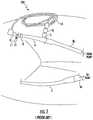
- a typical ECMO circuit 100 as shown in FIG. 1consists of multiple components including cannulas, tubing, an oxygenator, and pump with a controller.
- a heater-cooler elementmay be added for temperature management as well.
- a venous cannula 2is inserted either into a large vein, such as a femoral vein, or the right atrium of the heart for drainage of blood from the patient.
- an ECMO circuitcan provide gas exchange for patients with acute pulmonary failure, or both gas exchange and hemodynamic support for patients with acute cardiac or combined cardiopulmonary failure. In the setting of acute cardiac and pulmonary failure, ECMO can provide immediate restoration of perfusion and oxygen delivery to tissues, thereby preventing worsening acidosis, shock, multisystem organ failure and ultimately death and allowing for time for either organ recovery or diagnosis and intervention.
- ECMOis generally considered to be a supportive technology intended to provide oxygen and hemodynamic support to patients with acute cardio-pulmonary failure through a closed system.
- Many patients that require ECMOalso require invasive procedures for diagnosis and potentially intervention. Many of these procedures, such as left and right heart catheterization, percutaneous coronary intervention, or insertion of catheters for instillation of thrombolytics, require access to the cardiovascular system, which is usually established by inserting an introducer sheath into a peripheral vessel after obtaining access with a needle.
- institution of ECMOgenerally requires thorough systemic anticoagulation to increase blood flow and prevent clotting.
- vascular accessis often obtained in the clinical setting by palpating a patient's pulse as a landmark for locating the blood vessel.
- ECMOprovides laminar flow and a patient on ECMO may have very little or no difference in systolic or diastolic blood pressure, resulting in a very low pulse pressure. While a patient may have adequate blood pressure, there may be very little pulsatility and it may be difficult or impossible to palpate a pulse while on ECMO.
- obtaining vascular access in patients on ECMOmay be challenging and result in complications including vascular injury and bleeding.
- an ECMO circuitSince establishment of an ECMO circuit requires insertion of cannulas into the vascular system, the ECMO circuit itself has the potential to serve as an access point to the cardiovascular system and allow the performance of diagnostic and therapeutic procedures to promote the recovery of the patient. Utilizing the ECMO circuit itself for access to the cardiovascular system would circumvent the challenges and risks associated with attempting to access another blood vessel. However, an ECMO circuit is generally not used as a vascular access point in clinical practice as a safe and facile means of doing so does not exist with currently available technology.
- the arterial or in-flow cannula 4generally represents the most proximate component of the ECMO circuit to the patient's cardiovascular system.
- This arterial cannula 4is typically inserted into a large peripheral vessel, such as the femoral or axillary artery, or directly into the aorta.
- Most commercially produced cannulashave a small, perpendicular side port 5 with a Luer connector, as shown in FIG. 1 .
- This side port 5allows air to be eliminated from the circuit and also allows for establishment of a secondary circuit, such as for perfusion of blood to the ipsilateral limb.
- Such secondary circuitsare established by a secondary circuit connector 13 attaching to the side port 5 of the arterial cannula.
- Secondary circuit tubing 14directs blood from the side port 5 to a superficial cannula 10 , such as a superficial femoral arterial cannula.
- a superficial cannula 10such as a superficial femoral arterial cannula.
- Both the main arterial cannula 4 and the superficial cannula 10may be introduced into the artery at the same insertion point 12 , with the cannula 4 being directed toward the heart, and the superficial cannula 10 being directed toward the ipsilateral limb, such as the leg in a femoral arterial setting.
- the secondary circuittherefore allows perfusion into the ipsilateral leg and prevents ischemia and tissue damage in the leg.
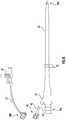
- an introducer sheath 15shown in FIG. 2
- the introducer sheath 15may also include a hub 16 with side arm 16 a for venting air out of the system through venting tubing 17 by operation of a valve 18 .
- the side port 5 of an ECMO arterial cannula 4represents a potential access point to the ECMO circuit for vascular access.
- current vascular introducer sheaths 15have no mechanism of interfacing with the side port 5 .
- arterial sheaths 15are too long and incompatible with the short right angle side port 5 provided in a cannula 4 .
- introducer sheaths 15provide no mechanism for establishing a hemostatic seal to the cannula 4 , which would be needed for safe insertion of a wire or catheter.
- the present inventionis directed to adaptors, caps, cannulas, tube couplers, and systems including combinations thereof to permit the cannulas of an ECLS system, such as an ECMO circuit, to be used as an access point to gain endovascular entry.
- the various componentsprovide the ability to interchangeably utilize the side port of a cannula not only for introduction of intervention devices, such as wires or catheters, into the cardiovascular system, but also for other purposes as well, such as establishing a secondary circuit for distal perfusion. Full occlusion of the side port is also made possible when the side port is not in use, to prevent blood stagnation and thrombus formation.
- the present inventionis directed to a variety of adaptors that enable the use of an ECMO circuit as a vascular access point, and systems for vascular access that include such adaptors.
- These adaptorscan interface with a standard cannulas currently used in ECLS systems, such as ECMO circuits, and provide an access point for intervention devices such as wires or catheters into the s system.
- the adaptors of the present inventioninclude curved or straight shafts having an angle that can negotiate the right angle of a standard cannula side port and provide directionality to a wire or catheter inserted therein.
- a hemostatic membraneallows for insertion of the intervention device without back bleeding.
- the present inventionis also directed to a modified cannula with an angled side port.
- modified cannulascan be used with an adaptor as described herein.
- An occlusive capis also provided that fully blocks the angled side port when vascular access or secondary perfusion is not needed. This occlusive cap prevents blood from stagnating in the angled side port, which could lead to thrombosis.
- Systems including the modified cannula, adaptor and occlusive capare also described.
- the present inventionis further directed to a tube coupler that can be spliced into the tubing of an established or pre-existing ECLS system, including ECMO circuits.
- the couplermay have a standard right angle side port, or may have an angled side port with interchangeable adaptor and occlusive cap.
- a series of couplersmay be inserted into the tubing of the bypass system, such as when a series of instruments or intervention devices must be inserted simultaneously for vascular access.
- Systems including the coupler with adaptors and/or occlusive caps, as previously described,are also included.
- FIG. 1is a diagram of a typical ECMO system of the prior art.
- FIG. 2is a diagram demonstrating the difficulties of direct access to an ECMO cannula.
- FIG. 3is a partial cross-section of one embodiment of an adaptor of the present invention shown inserted in an ECMO cannula.
- FIG. 3Ais a cross-section of the adaptor of FIG. 3 .
- FIG. 4Ashows the adaptor of FIG. 3 prior to insertion into an ECMO cannula.
- FIG. 4Bshows the adaptor of FIG. 4A being inserted into the ECMO cannula.
- FIG. 4Cshows the adaptor of FIG. 4A fully inserted into the ECMO cannula.
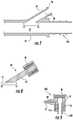
- FIG. 5Ais a cross-section of a second embodiment of an adaptor of the present invention.
- FIG. 5Bis a cross-section of a third embodiment of an adaptor of the present invention.
- FIG. 6shows a modified ECMO cannula, cap and adaptor of the present invention.
- FIG. 7is a cross-section of the modified ECMO cannula of FIG. 6 .
- FIG. 8is a cross-section of a modified cap of FIG. 6 .
- FIG. 9is a cross-section of the adaptor of FIG. 6 .
- FIG. 10is a cross-section showing the adaptor and modified ECMO cannula of FIG. 6 .
- FIG. 11is a cross-section showing the cap and modified ECMO cannula of FIG. 6 .
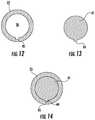
- FIG. 12is a cross-section of the sideport opening of one embodiment of the modified ECMO cannula of the present invention.
- FIG. 13is a cross-section of the occluding surface of one embodiment of the cap of the present invention.
- FIG. 14is a cross-section of the occluding surface of the cap of FIG. 13 when inserted in the sideport of the modified ECMO cannula of FIG. 12 .
- FIG. 15is one embodiment of a system using one version of a tubing connector with various adaptors of the present invention.
- FIG. 16is another embodiment of a tubing connector of the present invention.
- FIG. 17Adepicts standard bypass tubing before insertion of a tube coupler.
- FIG. 17Bdepicts the tubing of FIG. 17A cut in preparation of receiving a coupler.
- FIG. 17Cshows a coupler placed between sections of bypass tubing, where a cap is in place.
- FIG. 17Dshows the coupler of FIG. 17C where the cap is removed, in preparation for direct access.
- FIG. 17Eshows the coupler of FIG. 17D where an adaptor is placed in the side port of the modified cannula for direct access.
- FIG. 17Fshows the coupler and adaptor of FIG. 17E in which direct access of an insertion device to the ECMO system is achieved through the adaptor and tubing connector.
- FIG. 18shows another embodiment of the tube coupler system where multiple couplers are serially spliced into the same bypass tubing and each provides endovascular access for a different insertion device.
- FIG. 19shows still another embodiment of the tube coupler system in which a single coupler includes a plurality of access ports, where each access port permits entry of a different insertion device for endovascular access.
- the present inventionis directed to devices, such as adaptors, cannulas, tubing, and connectors that enable the use of an ECLS circuit, such as ECMO, as a vascular access point.
- the devices and systemsenable not only vascular access for an intervention device, such as a wire, catheter or the like, but also provide full occlusion of the side port of the ECMO cannula when not in use. They are interchangeable with each other depending on whether vascular access is desired or not, and are further interchangeable with tubing connectors for secondary circuits, such as to establish secondary perfusion to an ipsilateral limb.
- This level of accessibility and interchangeability of components with a side port of a long-term use cannulahas not been seen before. Further, the need to fully occlude the side port when not in use is of extreme importance in long-term systems, such as ECLS circuits, because of the increased potential for thrombus formation.
- the present inventionaddresses all of these needs not seen heretofor.
- the adaptors, cannulas, cap, tubing, couplers and systems of the present inventionmay be used with any appropriate cannulation or ECLS system, and is not limited to vascular applications.
- the devices and systems described hereincan be used with bypass systems, such as a cardiopulmonary bypass circuit, for temporary support such as during an open heart operation.
- bypass systemssuch as a cardiopulmonary bypass circuit
- the inventions described hereinmay be more preferably used with longer term support circuits, such as those in use over 6 hours or more.
- the terms “subject” and “patient”may be used interchangeably and refer to the individual who is on bypass in which intracorporeal access is desired.
- one aspect of the inventionincludes a variety of adaptors 30 designed for use with standard ECMO arterial cannulas 4 having a right angle side port 5 as an access point.
- These adaptors 30can successfully navigate or circumvent the 90° turn of the side port 5 of an arterial or in-flow cannula 4 without kinking or damage. They therefore permit access to the cannula lumen 7 , without obstructing the lumen, for access to the vascular system through the cannula 4 .
- the adaptor 30may be used instead of an introducer sheath 15 to access the vascular system, and enables access to the vascular system through the ECMO circuit without further percutaneous action.
- the adaptor 30includes a body 32 that acts as a hub for the remaining components of the adaptor 30 , and may be manipulated by an operator or user during insertion.
- the body 32is preferably made of a medical-grade plastic or other suitable material for medical use, and may be rigid.
- the body 32may include a side arm 37 that can be used for venting and otherwise removing air from the system, described in greater detail below.
- the adaptor 30also includes a shaft 33 that extends from one end of the body 32 .
- the shaft 33may extend at least partially into the body 32 on one end, and extends away from the body 32 on the opposite end.
- the shaft 33may include an elongate structure dimensioned to be inserted and pass through the side port 5 of a cannula 4 , as shown in FIG. 3A .
- the shaft 33may have a circular or tubular configuration, and a diameter that corresponds to, or is smaller than, the inner diameter of the side port 5 . Accordingly, the shaft 33 may fit inside the side port 5 , and may provide a snug fit in some embodiments.
- the shaft 33is at least as long as the side port 5 of a cannula 4 , and may extend into the cannula lumen 7 . In some embodiments, the shaft 33 may extend to the wall of the cannula 4 , but in at least one preferred embodiment the shaft 33 does not extend to the wall of the cannula 4 . Regardless of the embodiment, however, the shaft 33 of the present adaptor 30 is shorter in length than that of a standard introducer sheath 15 . The shorter length of the sheath 33 facilitates the navigation of the right angle side port 5 (discussed below) and prevents kinking of the shaft 33 when inserted into the side port 5 .
- the shaft 33may be made of a semi-flexible plastic material, such as fluorinated ethylene polypropylene or polyethet block amide plastics used in endovascular and other intervention systems, or other suitable medical-grade plastics and materials.
- a semi-flexible materialprovides sufficient rigidity to maintain its shape for directional guiding of a wire or catheter, but is flexible enough to bend or flex slightly as needed during the insertion process and to prevent damage to the shaft 33 upon the introduction of a medical device therein.
- the body 32 of the adaptor 30may be made of a similar semi-flexible material as the shaft 33 , or may be made of more rigid material than the shaft 33 .
- the shaft 33may have a variety of configurations that enables modifying an angle of insertion of an intervention device, such as a wire or catheter, inserted into the adaptor 30 and directs the intervention device into the cannula lumen 7 .
- an intervention devicesuch as a wire or catheter
- the shaft 33 ais curved.
- the curved shape of the shaft 33 aprovides directionality to a medical device introduced therein, such as a wire or catheter. When positioned correctly, the curved shaft 33 a reliably directs the wire or catheter introduced therein toward the patient's heart, rather than back in the direction of the ECMO system.
- the curved shaft 33 ais long enough to extend into the cannula lumen 7 when inserted, but is also short enough in length to easily navigate the right angle of the side port 5 during insertion, as depicted through FIGS. 4A-4C .
- an adaptor 30 a having a curved shaft 33 ais provided.
- the distal opening of the curved shaft 33 ais aligned with the opening of the side port 5 , as shown in FIG. 4B .
- the distal end of the curved shaft 33 ais inserted into the side port 5 of the cannula 4 , and the adaptor 30 a is rotated along the directional arrow shown in FIG.
- the shaft 33 aprevents the shaft 33 a from kinking at the inner wall of the cannula lumen 7 , since in at least one embodiment the curved shaft 33 a is not long enough to reach the opposite wall of the cannula lumen 7 during insertion. In some embodiments, the curved shaft 33 a may be long enough to reach the opposite wall of the cannula lumen 7 during insertion, but in these embodiments the semi-flexible material of the curved shaft 33 a allows it to flex and deflect off of the cannula wall, and resiliently keep its curved shape.
- a connector 35can be tightened to selectively and releasable secure the adaptor 30 a to the cannula 4 , thereby securing the adaptor in place and preventing bleeding around it.
- the shaft 33 bhas a straight configuration and extends substantially linearly from the body 32 of the adaptor 30 b .
- the distal end of the shaft 33 b opposite of the body 32includes a deflector 39 that protrudes or extends from an interior wall of the shaft 33 b at an angle, thereby creating an angled surface for upon which a wire, catheter or other medical device inserted through the adaptor 30 b may be deflected in a gentle curve to direct it into the cannula lumen 7 .
- the deflector 39changes the angle of the intervention device 60 from the initial angle of insertion to a different angle that directs the intervention device 60 into the cannula lumen 7 .
- the deflector 39may be made of the same semi-flexible material as the rest of the shaft 33 b , as discussed previously, or may be made of a slightly more rigid material that resists flexing when pressure is applied, so as to direct an intervention device 60 , such as a wire or catheter, appropriately and not lose its shape.
- an intervention device 60may be any diagnostic and therapeutic device used in medical procedures, and is not limited to wires or catheters.
- the deflector 39is made of a hard medical-grade plastic, such as polycarbonate or nylon, although other suitably rigid materials are also contemplated.
- the entire shaft 33 b,c and deflector 39may be made of a hard plastic, polycarbonate or nylon, or other rigid material.
- the deflector 39may be at the terminal end 47 of a straight shaft 33 b , such that the shaft 33 b has an angled end.
- the straight shaft 33 cmay include a deflector 39 as before, but has a flat or straight terminal end 47 outer end.
- the shaft 33 b,cmay have an opening 38 at the side at the terminal end 47 . Accordingly, the opening 38 is facing or pointed in the direction of the patient's heart, so as to appropriately direct a wire or catheter exiting from the shaft 33 b,c .
- the straight shaft 33 b,cis longer in length than the side port 5 , but is shorter than the distance to the opposite wall of the cannula 4 .
- the right angle side port 5does not pose a navigational risk in these straight shaft 33 b,c embodiments, since the straight shaft 33 b,c easily conforms to the straight channel 8 of the side port 5 , and the internal deflector 39 creates the required angular change to direct an inserted wire or catheter toward the patient's heart.
- the shaft 33provides access for an intervention device 60 to the cannula lumen 7 , and modifies the angle of insertion of the intervention device 60 and directs the intervention device 60 into the cannula lumen 7 .
- the cannula lumen 7has an axial flow path 70 of fluid (such as blood from an ECMO system) being directed through it.
- the shaft 33 of the adaptor 30changes the direction of the intervention device 60 upon insertion and directs it not only into the cannula lumen 7 , but specifically in the direction of, or consistent with, the axial flow path 70 of the cannula lumen 7 . In at least one embodiment, this is toward the patient's heart, for cardiopulmonary intervention.
- the shaft 33may include a flange 34 that has a wider diameter than the remainder of the shaft 33 .
- the flange 34may be circumferentially disposed around the shaft 33 and extend radially away from the shaft 33 .
- the flange 34is dimensioned to correspond with and abut a terminal lip 6 at the outermost edge of the side port 5 when the adaptor 30 is fitted on the side port 5 . In this manner, the flange 34 may limit how far the shaft 33 may enter the side port 5 and cannula lumen 7 .
- the adaptor 30may further include a connector 35 , as shown in FIGS. 3A, 5A and 5B .
- the connector 35is a fitting that removably secures the adaptor 30 to the side port 5 of the cannula 4 .
- the connector 35may be any suitable fitting for selectively releasable connection, such as a snap fitting, or a Luer connector that connects by screw action through a series of threads on the inside of the connector 35 . These threads may interact with the lip 6 of the side port 5 , such that as the connector 35 is turned or rotated about the side port 5 , the lip 6 engages and is moved through the threads of the connector 35 .
- the connector 35is a floating Luer connector that rotates independently of the remainder of the adaptor 30 , such as the shaft 33 .
- Such floating connector 35may be preferable in embodiments where maintaining the direction or alignment of the opening 38 of the shaft 33 within the cannula lumen 7 is important, as in FIGS. 3-5B .
- the connector 35may be secured to and/or rotate with the adaptor 30 or shaft 33 .
- the connector 35may be integrated into the adaptor 30 , such as in the body 32 of the adaptor 30 .
- the flange 34 of the shaft 33may act as a washer between the connector 35 and the lip 6 of the side port 5 , forming a seal when the connector 35 is tightened down onto the side port 5 .
- the body 32may include a cavity 49 on the underside which is correspondingly shaped to the connector 35 , such that at least a portion of the connector 35 may be inserted into the cavity 49 of the body 32 , as seen in FIG. 3A for example.
- the adaptor 30also includes an adaptor lumen 31 extending through and connecting the interior of the body 32 and shaft 33 , shown in FIGS. 3A, 5A and 5B .
- the adaptor lumen 31provides a hollow interior through which an intervention device 60 such as a wire or catheter may be introduced.
- the adaptor lumen 31may be a single lumen, or may be separate lumens of the body 32 and the shaft 33 that are continuous with one another. Accordingly, in some embodiments, the adaptor lumen 31 a is curved through a curved shaft 33 a , as in FIG. 3A . In other embodiments, the adaptor lumen 31 b,c is straight through a majority of its length, and is angled at the distal end of the shaft 33 b,c.
- the adaptor lumen 31is in fluidic communication with the cannula lumen 7 when the adaptor 30 is in place. Specifically, the adaptor lumen 31 extends through the body 32 and shaft 33 of the adaptor 30 , and ends at the opening 38 of the distal end of the shaft 33 . Therefore, the adaptor lumen 31 provides exterior access to the cannula lumen 7 of the ECMO system, including the axial flow path 70 thereof.
- the adaptor lumen 31may also be in fluidic communication with a passage 48 extending through a side arm 37 of the adaptor 30 .
- any air that may be present in the cannula lumen 7 and the adaptor lumen 31may be removed by selective venting through the passage 48 of the side arm 37 , such as by operation of a valve connected to the side arm 37 through vent tubing 17 , as in FIG. 3A .
- the adaptor lumen 31is dimensioned to receive an intervention device 60 such as wires and catheters, which may be up to about 7 French in diameter, or greater in some embodiments.
- the flange 34 of the shaft 33 and the connector 35form a hemostatic seal with the side port 5 , as mentioned previously, so that blood flowing through the ECMO system will not be lost during vascular access.
- the adaptor 30may include a membrane 36 opposite of the shaft 33 through which a wire, catheter or other suitable diagnostic, therapeutic or other medical intervention device 60 may be passed to enter the adaptor 30 and gain access to the ECMO system and vascular system.
- the membrane 36is a hemostatic diaphragm, such as a silicone or other soft biocompatible plastic disc with a perforating slit(s) for access, as is used in insertion sheaths 15 .
- the membrane 36is disposed in the body 32 of the adaptor 30 and spans the distance between the edge of the adaptor lumen 31 and the outer edge or exterior of the body 32 .
- the membrane 36is coextensive with a top surface of the adaptor 30 , as in FIGS. 3A, 5A and 5B .
- the top surface of the adaptor 30may not be uniformly flat, but may recess in, as in FIG. 9 .
- the membrane 36spans from the adaptor lumen 31 to the outer edge of the body 32 , which is the recessed portion. Regardless of configuration, the membrane 36 allows access to the adaptor lumen 31 while maintaining hemostatic conditions and preventing back bleeding upon insertion of an intervention device 60 therein.
- the inventionalso includes various systems for vascular access 200 .
- Each system 200includes a cannula 4 and an adaptor 30 as described herein.
- a vascular access system 200 aincludes a cannula 4 and an adaptor 30 a having a curved shaft 33 a , as in FIG. 3A .
- the vascular access system 200 bincludes a cannula 4 and an adaptor 30 b having a straight shaft 33 d terminating in an angled deflector 39 , as in FIG. 5A .
- the vascular access system 200 cincludes a cannula 4 and an adaptor 30 c having a straight shaft 33 c and a flat terminal end, with an internal deflector 39 , as in FIG. 5B .
- a cannula 4 and an adaptor 30 chaving a straight shaft 33 c and a flat terminal end, with an internal deflector 39 , as in FIG. 5B .
- the present inventionis also directed to a modified cannula 24 that can be used in an ECLS system in place of a standard arterial cannula 4 , such as an ECMO vascular cannula.
- the modified cannula 24is made of a flexible medical-grade plastic, silicon, or polymer material, or other material suitable for insertion and residence in a patient.
- the modified cannula 24includes an elongate portion 29 extending between a proximal end 29 a and an opposite distal end 29 b .
- the proximal end 29 ais positioned closest to the pump of the bypass system, and has an opening at its terminal end and a diameter sized to receive and form a tight seal with the bypass tubing 3 b around its perimeter.
- such bypass tubing 3 bmay be 3 ⁇ 8 inch to 1 ⁇ 2 inch in diameter, and the proximal end 29 a may have a diameter ranging from 6 to 51 French depending on the particular application and whether it is used on an adult, child or infant.
- the proximal end 29 aincludes ribs, barbs, serrations, or other frictional elements that engage the interior of the bypass tubing 3 b upon insertion and maintains or facilitates a tight seal with the tubing 3 b . Accordingly, when attached to the bypass tubing 3 b , the proximal end 29 a of the modified cannula 24 receives blood from the ECLS system, such as an ECMO system.
- the opposite distal end 29 b of the modified cannula 24is dimensioned to be inserted into a subject or patient, such as a blood vessel for vascular access, and more in particular an artery, such as the femoral artery or aorta, or a vein, such as the femoral vein or internal jugular vein.
- a subject or patientsuch as a blood vessel for vascular access, and more in particular an artery, such as the femoral artery or aorta, or a vein, such as the femoral vein or internal jugular vein.
- the distal end 29 bmay have a diameter ranging from 14 to 22 French, although smaller or larger sizes are also contemplated.
- the distal end 29 bis preferably narrower than the proximal end 29 a , as in FIGS. 6 and 7 .
- the distal end 29 b and proximal end 29 amay have the same diameter, or the distal end 29 b may have a larger diameter than the proximal end 29 a .
- the distal end 29 bis also made of a flexible medical-grade plastic, silicon, or polymer material, or other suitable material, so as to avoid damaging or puncturing the blood vessel.
- the distal end 29 bmay also include an opening(s) at or near the distal tip to allow reinfusion of blood into the surrounding blood vessel from the modified cannula 24 .
- the modified cannula 24may include a depth guide(s) 22 located along the length of the elongate portion 29 .
- the depth guide(s) 22provide a visual indicator for a user, such as a medical practitioner, of how far to insert the distal end 29 b of the modified cannula 24 into the subject.
- the distal end 29 b of the modified cannula 24is inserted into the patient at an incision point until the depth guide(s) 22 reaches the incision.
- the depth guide(s) 22therefore provides a maximum limit for insertion.
- the depth guide 22may be a collar or series of collars disposed circumferentially around the exterior of the elongate portion 29 of the modified cannula 24 .
- the depth guide 22may be a marking or series of markings on or integrally formed in the wall of the modified cannula 24 , such as printed on or engraved in the exterior surface of the modified cannula 24 .
- the modified cannula 24also includes a modified cannula lumen 27 extending through the length of the modified cannula 24 from the opening at the proximal end 29 a to the opening at the distal end 29 b . Accordingly, the modified cannula lumen 27 provides an axial flow path 70 ′ through which fluid, such as blood, may pass during ECMO circulation.
- the modified cannula lumen 27has a diameter similar to that of the modified cannula 24 , and in at least one embodiment takes up a majority of the inner volume of the modified cannula 24 .
- the modified cannula 24further includes an angled side port 25 that extends from the surface of the modified cannula 24 .
- the angled side port 25extends away from the surface at an angle, which may be any angle other than 90°.
- the angled side port 25extends from the surface of the modified cannula 24 at an acute angle less than 90°, such as in the range of 10° to 40° from the modified cannula 24 wall in at least one embodiment.
- the angle of the angled side port 25is in the range of 25° to 35°.
- the angled side port 25terminates at a lip 26 having a wider diameter than the rest of the angled side port 25 , so as to form an overhanging portion.
- the angled side port 25may also have a thread to allow interaction with Luer connections or other counterthreads on the connector 35 of adaptors 30 .
- the angled side port 25also has an opening at the terminal end, and an angled side port channel 28 extending through the angled side port 25 in fluid communication with the opening on one end and the modified cannula lumen 27 on the opposite end. Accordingly, the angled side port 25 provides exterior access to the modified cannula lumen 27 , and therefore to the vascular system for endovascular diagnostic and therapeutic procedures.
- the angled side port 25 of the modified cannula 24provides a number of benefits over the standard right angle side ports 5 of current vascular arterial cannulas 4 .
- the angle of the angled side port 25directs an incoming wire, catheter or other inserted medical device to more closely align with the modified cannula lumen 27 in a direction toward the heart of the patient. This facilitates the insertion of such a device without having to navigate around a right angle, as with standard cannulas 4 , thereby preventing kinking and obstruction of the wire or catheter.
- Cardiopulmonary bypass cannulas with an angled side arm or a Y-shapehave been described in the prior art.
- these cannulashave several disadvantages that limit their utility in an ECMO system.
- a typical bypass cannulawhen a typical bypass cannula is inserted into a vessel, it may occlude blood flow to distally located tissues.
- FIG. 1when a cannula is inserted into the femoral artery, blood flow to the entire ipsilateral leg may be jeopardized.
- the right angle side port 5 of a cannula 4can be used to establish a secondary circuit 14 to direct a portion of the blood flow in the opposite direction to the cannula 4 .
- Blood flowmay be directed out of the right angle side port 5 of the cannula 4 and down the ipsilateral leg to separately perfuse the leg.
- Secondary circuits for distal perfusionare not always necessary, and may not be needed the entire time the patient is supported on the ECMO system, but they are frequently used. Thus, the ability to establish of a downstream flow circuit is an important option when using long-term bypass systems such as ECMO.
- cardiopulmonary bypass cannulas with angled side arm previously described in the prior artlacks the requisite structure to establish a connection for a secondary circuit 14 for distal perfusion.
- the modified cannula 24 with angled side port 25 of the present inventionincludes a lip 26 at the terminal end, as seen in FIG. 7 .
- This lip 26provides a surface on which a connector, such as a Luer connector, can be used to engage for secure yet selectively removable connection.
- a Luer connector commonly used as a secondary tubing connector 13shown in FIG. 1
- can engage the lip 26 of the angled side port 25 of the modified cannula 24shown in FIG. 7 , to establish a secondary circuit as previously described for distal perfusion.
- the lip 26 of the angled side port 25is dimensioned to fit within the grooves, threads, or tracks of a connector, such as a Luer connector having internal threading for connection by screwing action.
- a connectorsuch as a Luer connector having internal threading for connection by screwing action.
- Common cardiopulmonary bypass cannulaseven those with angled side arms, lack this structure.
- Luer connectorsare described here as removably engaging the lip 26 of the angled side port 25 , it should be appreciated that other types of connectors could also be used to removably engage the lip 26 for a secure connection, such as snap on connectors.
- blood flow along the main lumen 7 of the cannula 4is laminar.
- a typical angled side armrepresents an arm with a blind end, since laminar flow does not penetrate the side arm.
- the lack of flow in the side armcreates a potential for stagnant blood to pool in the side arm, which may result in thrombus formation, particularly during periods of prolonged support on ECMO. If a thrombus forms and is later dislodged, it may result in devastating complications including stroke, myocardial infarction, ischemic bowel, or ischemia of other tissues. Therefore, known cardiopulmonary bypass cannulas with an angled side arm or a Y-shape cannot be used in ECMO systems.
- cardiopulmonary bypass cannulas with an angled side arm or a Y-shapehave permanent valves located within the side arm. Such permanent valves may increase the risk of stagnant blood flow and thrombus formation.
- the angled side port 25 of the modified cannula 24 of the present inventionlacks such permanent valves that would lead to stagnant blood flow and thrombus formation.
- the angled side port 25 of the modified cannula 24 of the present inventionis designed to coordinate with a specialized occlusive cap 40 for use when access to a secondary circuit 14 or endovascular access is not needed.
- the occlusive cap 40 of the present inventionis designed to fit inside the angled side port channel 28 of the angled side port 25 and occlude substantially all of the angled side port 25 , such that blood does not flow into the angled side port 25 from the ECMO system when access is not needed. This prevents blood stagnation and potential thrombus formation, and is not available with known ECMO or cardiovascular bypass cannulas.
- the occlusive cap 40is correspondingly dimensioned in size and shape to fit inside the angled side port channel 28 and provide a tight fit therein.
- the occlusive cap 40includes an occluding member 42 terminating in an occluding surface 41 , as seen in FIGS. 8, 11, 13 and 14 .
- the occluding surface 41blocks the angled side port channel 28 and prevents blood from entering. It therefore prevents blood stagnation and potential thrombus formation.
- FIG. 11depicted in the cross-section of FIG. 11 and the view along line 14 - 14 shown in FIG.
- the edges of the occluding surface 41are adjacent to and abut the interior surface of the angled side port channel 28 , so as to form a tight fit therewith.
- the occluding surface 41is flush or coextensive with the wall of the modified cannula lumen 27 , such that the occluding member 42 of the occlusive cap 40 does not extend into the modified cannula lumen 27 and laminar blood flow through the modified cannula lumen 27 is not disrupted.
- the occluding member 42may extend into the modified cannula lumen 27 , such as to ensure the angled side port channel 28 is entirely blocked.
- the occluding surface 41may have a locking member 44 , as shown in FIGS. 13 and 14 .
- This locking member 44is located along the perimeter of the occluding surface 41 and is correspondingly dimensioned with a receiver 45 located in the inner perimeter or edge of the angled side port 25 , such as in the angled side port channel 28 .
- the locking member 44 and receiver 45correspondingly fit together to form a tight fit, but may also provide locking engagement for securely retaining the occluding surface 41 in the angled side port 25 in a particular orientation.
- This engagementmay also be used to ensure the occlusive cap 40 is fully inserted and/or properly aligned within the angled side port channel 28 so that the occluding surface 41 is flush or fully coextensive with the wall of the modified cannula lumen 27 , as the locking member 44 and corresponding receiver 45 may only interact and engage in a particular configuration.
- the locking member 44is an extension that extends from the perimeter of the occluding surface 41
- the receiver 45is a recess formed in the angled side port 25 having a corresponding shape, contour and dimension to the locking member 44 .
- the locking member 44may be located in the angled side port 25 and the receiver 45 may be located in the perimeter of the occluding surface 41 .
- the locking member 44 and receiver 45may have any shape, dimension or contour permitted by the occluding surface 41 and angled side port 25 , so long as they coordinate together.
- the locking member 44may be a keyed extension
- the receiver 45may be a rail or track
- either or both the locking member 44 and receiver 45may include threading for coordinated interaction.
- the occluding member 42may have an elongate shape, such as a cylinder or shaft that extends at least a portion of the length of the occlusive cap 40 . In some embodiments, the occluding member 42 extends the entire length of the occlusive cap 40 . At least a portion of the occluding member 42 has a diameter that is substantially the same as or slightly smaller than the diameter of the angled side port channel 28 . In one embodiment, the entire length of the occluding member 42 has a diameter corresponding to the diameter of the angled side port channel 28 of the modified cannula 24 .
- only a portion of the occluding member 42has a diameter corresponding to the diameter of the angled side port channel 28 . This portion may be located anywhere along the occluding member 42 , such as at an end or anywhere along the length of the occluding member 42 .
- the occluding member 42may be at least as long as the angled side port channel 28 and the angled side port 25 in some embodiments. In a preferred embodiment, the occluding member 42 is the same length as the angled side port channel 28 . In some embodiments, the width or diameter of the occluding member 42 is the same as that of the occluding surface 41 . In other embodiments, the width or diameter of the occluding member 42 is less than that of the occluding surface 41 , or may vary in its diameter over its length.
- the occlusive cap 40may also include a cap connector 43 , as shown in FIG. 8 .
- the cap connector 43selectively retains the occlusive cap 40 on the modified cannula side port 25 for selectively reversible securing.
- the cap connector 43is dimensioned to removably engage the lip 26 of the angled side port 25 to secure the occlusive cap 40 in place upon insertion into the angled side port 25 .
- the cap connector 43may be shaped as a Luer connector, such as a floating or fixed Luer connector, and may include threads disposed along an inner surface for receiving the lip 26 of the angled side port 25 .
- the cap connector 43may be integrally formed with the occlusive cap 40 , as in FIG. 8 , although in other embodiments it may be formed separately and attached to the occlusive cap 40 , such as at the occluding member 42 .
- the cap connector 43allows the occlusive cap 40 to be secured to the angled side port 25 when the modified cannula 24 does not need to be accessed.
- the occlusive cap 40 and modified cannula 24 described hereintogether form an occlusion system 300 , as seen in FIG. 11 .
- the occlusive cap 40is fully inserted in the angled side port 25 of the modified cannula 24 , the laminar blood flow through the bypass system is substantially entirely occluded from the angled side port 25 . This is important to prevent thrombus formation in long-term use systems such as ECLS.
- the occlusive cap 40When access to the modified cannula lumen 27 is desired, such as for the insertion of a wire or catheter or to establish a secondary circuit for distal perfusion, the occlusive cap 40 may be removed from the angled side port 25 .
- the bypass tubing 3 bmay be clamped upstream of the modified cannula 24 prior to removal of the occlusive cap 40 , such that blood flow through the system is temporarily interrupted. This prevents blood from seeping into the angled side port channel 28 upon removal of the occluding surface 41 and the occlusive cap 40 .
- secondary circuit tubingmay be connected to the angled side port 25 in a similar fashion as it would connect to a right angle side port 5 .
- the clamp on the bypass tubing 3 bmay then be released, reestablishing the blood flow through the system, which now includes a secondary circuit for distal perfusion.
- an adaptor 30 dmay be attached to the angled side port 25 during temporary interruption of the ECMO system, as described below. After either is attached, the clamp may be removed and ECMO flows reinstituted.
- the present inventionalso includes an adaptor 30 d , as seen in FIGS. 9 and 10 .
- the adaptor 30 d and occlusive occlusive cap 40are interchangeable, the adaptor 30 d may also be considered an insertion cap, and the terms are used interchangeably herein.
- the adaptor/insertion cap 30 dincludes a body 32 , a membrane 36 for hemostatic access, and an adaptor or insertion lumen 31 d extending from the membrane 36 and through the body 32 , similar to those of the previously described adaptors 30 a,b,c .
- the adaptor/insertion cap 30 dis used with the angled side port 25 of the modified cannula 24 to permit exterior access to the modified cannula lumen 27 , and thus the ECMO system for endovascular entry.
- the adaptor 30 dneed not provide directionality for the insertion of a wire or catheter since that function is already provided by the angle of the angled side port 25 . Therefore, in at least one embodiment the adaptor/insertion cap 30 d may not include a shaft 33 or other structure that extends into the angled side port channel 28 of the angled side port 25 .
- the adaptor or insertion lumen 31 dis in fluid communication with the angled side port channel 28 when the adaptor/insertion cap 30 d is connected to the angled side port 25 .
- the adaptor/insertion cap 30 dincludes a shaft 33 d .
- the adaptor lumen 31 dis sized to coordinate with the angled side port channel 28 , and may be the same or similar diameter as the angle side port channel 28 .
- the adaptor lumen 31 dis sized to allow the passage of wires, catheters and other medical devices that may be used for cardiovascular interventions, such as 7 French or greater. Accordingly, an intervention device 60 can be passed through the hemostatic membrane 36 and enter the adaptor lumen 31 d , pass through the adaptor lumen 31 d directly into the angled side port channel 28 , and on into the modified cannula lumen 27 .
- the adaptor/insertion cap 30 dmay include a shaft 33 d that is straight and may be shorter than the shafts 33 a,b,c of the previously discussed adaptors 30 a,b,c .
- the shaft 33 dmay extend into at least a portion of the angled side port channel 28 , or even into the modified cannula lumen 27 .
- the shaft 33 dmay be 7 French in diameter or greater, such as to permit the passage of intervention devices such as medical devices for cardiovascular intervention, but still fits within the angled side port channel 28 .
- the shaft 33 dmay be integrally formed in the body 32 of the adaptor/insertion cap 30 d , or may attach to the body 32 such as by secure attachment as with adhesive or molding.
- the adaptor/insertion cap 30 dmay attach to the exterior of the angled side port 25 , such as by engaging the lip 26 of the angled side port 25 with a connector 35 as previously described. Because directionality is not a function of the adaptor 30 d with an angled side port 25 , the connector 35 of the adaptor 30 d may be fixed, formed in or integral with the body 32 of the adaptor 30 d , as shown in FIG. 9 . Thus, when the adaptor 30 d is attached to the angled side port 25 , the entire body 32 may be rotated around the angled side port 25 , to provide a secure, selectively reversible connection such as by screw-type action of threading of the connector 35 with the lip 26 of the angled side port 25 .
- the connector 35may be a floating Luer connector as previously described, or a retaining structure that permits the adaptor 30 d to slide or snap onto the lip 26 of the angled side port 25 , whereby the lip 26 retains the adaptor/insertion cap 30 d in place.
- the present inventionalso include another embodiment of a vascular access system 200 d including a modified cannula 24 having an angled side port 25 and an adaptor/insertion cap 30 d having a shorter shaft 33 d as described above, such as depicted in FIG. 10 .
- the adaptor/insertion cap 30 dand specifically the shaft 33 d , provides exterior access of an intervention device 60 to the modified cannula lumen 27 so as to change the angle of insertion of the insertion device 60 to be inline with or consistent with the axial flow path 70 ′.
- the cannulamay not be limited to one side port.
- the cannulamay have one or more angled side ports, right angle side ports, or some combination thereof.
- the present inventionalso includes a tube coupler 50 that may be inserted or spliced into ECMO or any bypass tubing to provide additional side ports 5 , 25 for endovascular access.
- a tube coupler 50may be inserted or spliced into ECMO or any bypass tubing to provide additional side ports 5 , 25 for endovascular access.
- some patientsarrive at a medical facility with an ECMO or other ECLS system already in place, in which the arterial cannula 4 may not have a side port 5 for endovascular access, and yet endovascular access may become necessary at some point while the patient is on support.
- the arterial cannula 4 of the ECLS systemmay only have a single side port 5 , but multiple devices (such as wires, catheters, etc.) may be needed to be inserted at the same time for simultaneous endovascular access, such as for coordinated actions to perform a medical procedure.
- the side port 5 and its hemostatic membrane 36may allow only one device through at a time, in order to maintain the hemostatic seal and prevent back bleeding. Since multiple couplers could be inserted into an ECLS circuit, the tube coupler 50 of the present invention therefore provides a way to introduce additional side ports 5 , 25 for additional points of access to the ECMO or other ECLS system.
- the tube coupler 50includes a first end 52 having a first end opening 56 , and an opposite second end 53 with a second end opening 57 , and a coupler body 51 disposed there between.
- the first and second ends 52 , 53are sized and shaped to accommodate and selectively matingly fit independent or separate sections of bypass tubing 3 b , such as ECMO tubing, on an arterial side of the bypass system.
- the first and second ends 52 , 53may be slightly narrower in diameter than the coupler body 51 of the tube coupler 50 , and in some embodiments may taper slightly, to allow a tight hemostatic seal when the tubing 3 b is attached.
- the first and second ends 52 , 53may have ribs, barbs, serrations, beveling, or other frictional structure to promote a tight seal and retention of the ECMO or bypass tubing 3 b . Accordingly, the first and second ends 52 , 53 may have a similar structure to the proximal end 9 a of a standard arterial cannula 4 , as discussed previously, although it is not required. In some embodiments, the first and second ends 52 , 53 have the same diameters and structural features. In other embodiments, the first and second ends 52 , 53 may have different diameters and structural features from one another.
- the coupler body 51extends between the first and second ends 52 , 53 and may have an elongate length. In a preferred embodiment, the coupler body 51 may be a cylinder, although other shapes and configurations are contemplated.
- a coupler lumen 54extends through at least a portion of the tube coupler 50 at the coupler body 51 . In at least one embodiment, the coupler lumen 54 extends from the first end opening 56 to the second end opening 57 and through the coupler body 51 such that the coupler lumen 54 provides an axial flow path 70 ′ for fluid such as blood to flow entirely through the tube coupler 50 when inserted in a bypass system.
- the coupler lumen 54thus allows the tube coupler 50 to be inserted into, and become part of, an established bypass system and permit the continued functioning of the bypass system.
- the tube coupler 50further includes a access port 55 located along the coupler body 51 .
- the access port 55may be a right angle side port 5 , as shown in FIG. 15 , such as is provided on commercially available arterial cannulas 4 as described above.
- the access port 55includes a length that extends away from the coupler body 51 of the tube coupler 50 .
- the access port 55defines a access port channel 58 extending through at least a portion of the interior of the access port 55 , which is in fluid communication with the coupler lumen 54 at one end, and has an opening at the other end for receiving the shaft 33 of an adaptor 30 as previously described, such as adaptors 30 a,b,c .
- the access port channel 58provides exterior access to the coupler lumen 54 such that a wire, catheter or other intervention device 60 may be inserted through a hemostatic membrane 36 within such adaptor 30 , as previously described, and be inserted into the access port channel 58 of the tube coupler 50 , and on into the coupler lumen 54 consistent with the axial flow path 70 ′ and bypass tubing 3 b.
- the tube coupler 50 ′includes an angled access port 55 ′, such as the angled side port 25 previously described in connection with the modified cannula 24 .
- the tube coupler 50 , 50 ′may include a traditional access port 55 or angled access port 55 ′ providing an access point to the interior of the tube coupler 50 , 50 ′, and therefore, the endovascular system.
- the angled access port 55 ′is located along the coupler body 51 of the tube coupler 50 ′, and may have any angle relative to the coupler body 51 as may promote ease of insertion of intervention devices 60 .
- the angle of the angled access port 55 ′may be any angle between 0° up to 90°.
- the angled access port 55 ′extends from the coupler body 51 and defines an angled access port channel 58 ′ extending through at least a portion of the interior of the angled access port 55 ′, which is in fluid communication with the coupler lumen 54 at one end, and has an opening at the other end for receiving an adaptor/insertion cap 30 d and/or shaft 33 d as previously described.
- the angled access port channel 58 ′provides exterior access to the coupler lumen 54 and axial flow path 70 ′′ therein such that a wire, catheter or other intervention device 60 may be inserted through a hemostatic membrane 36 within such adaptor 30 d , as previously described, and be inserted into the access port channel 58 ′ and axial flow path 70 ′′ of the tube coupler 50 ′, and on into the coupler lumen 54 and bypass tubing 3 b , as shown in FIG. 17F .
- the tube coupler 50 ′may also coordinate with the adaptor/insertion cap 30 d and occlusive cap 40 as previously described, either to provide endovascular access through the tube coupler 50 ′ or to seal off and occlude the angled access port 55 ′ when access is not desired. Accordingly, the tube coupler 50 , 50 ′ may comprise a part of a vascular access system 400 , 400 ′, respectively, in conjunction with an adaptor 30 as described herein, such as in FIG. 17F . The tube coupler 50 , 50 ′ may also be part of an occlusion system 300 ′ in conjunction with a occlusive cap 40 , as in FIG. 17C . The angled access port 55 ′ of the tube coupler 50 ′ can also be used to establish a secondary circuit for distal perfusion, as previously described.
- FIGS. 17A-17Fdemonstrate the steps of inserting a tube coupler 50 , 50 ′ into an already established ECLS system.
- a tube coupler 50 ′ with angled access port 55 ′is shown, but it should be appreciated that a tube coupler 50 with a right angle access port 55 would be inserted in a similar manner.
- a location along the bypass tubing 3 b where the tube coupler 50 ′ is to be insertedis identified. This location may be anywhere in the bypass system, but is preferably on the arterial side of the bypass system. In at least one embodiment, the location is proximate to, and upstream or proximal to, the location for intervention device use.
- the bypass systemis temporarily interrupted, such as by clamping, crimping or otherwise restricting the bypass tubing 3 b on either side, or at least upstream of, the insertion location. This prevents the flow of blood through the ECMO system, and allows the tubing to be cut without loss of blood.
- the bypass tubing 3 bis then cut downstream of the restriction point, resulting in two pieces of bypass tubing, as seen in FIG. 17B .
- the proximal piece 3 b ′ of bypass tubingis located with the restriction point, and is closer to the pump of the ECMO system.
- the distal piece 3 b ′′ of bypass tubingis located downstream of the cut in the tubing, and is closer to the arterial incision 12 where the bypass system is reintroduced back into the subject or patient.
- the tube coupler 50 ′is then inserted between the proximal piece 3 b ′ and distal piece 3 b ′′ of bypass tubing, as shown in FIG. 17C .
- the first end 52 of the tube coupler 50 ′is joined to the proximal piece 3 b ′ of the bypass tubing
- the opposite second end 53 of the tube coupler 50 ′is joined to the distal piece 3 b ′′ of bypass tubing.
- the first and second ends 52 , 53 of the tube coupler 50 ′will be oriented such that the angled access port 55 ′ opens toward the proximal piece 3 b ′ of bypass tubing, such that an intervention device 60 inserted therein is directed toward the distal piece 3 b ′′ and toward the heart of the subject.
- a occlusive cap 40may already be inserted in the angled side port 25 in a fully occluding position.
- the coupler lumen 54is in fluid communication with both the proximal piece 3 b ′ and distal piece 3 b ′′ of bypass tubing, defining a flow path with the tubing such that as blood flows through the bypass tubing it enters the proximal piece 3 b ′, then the coupler lumen 54 , then the distal piece 3 b ′′ of bypass tubing on its path from the oxygenator to the patient's heart.
- the access port channel 58 , 58 ′is occluded and blood is prevented from pooling and stagnating in the access port 55 , 55 ′.
- the occlusive cap 40When access to the bypass system is desired, such as to establish a secondary circuit as previously described or to gain endovascular access for medical intervention, the occlusive cap 40 may be removed from the access port 55 , 55 ′, as depicted in FIG. 17D .
- An adaptor 30 das previously described, is then inserted and attached to the access port 55 , 55 ′, as shown in FIG. 17E .
- an intervention device 60such as a wire or catheter or other suitable device may be inserted into the tube coupler 50 ′, as in FIG. 17F .
- the intervention device 60enters through the membrane 36 of the adaptor 30 d and continues to advance through the shaft 33 d , into the coupler lumen 54 , and on into the distal piece 3 b ′′ of bypass tubing until the particular site for intervention is reached.
- the tube coupler 50 , 50 ′may be inserted, such as spliced, into an already established ECLS system, such as an ECMO system.
- the tube coupler 50 , 50 ′may be included in an ECLS system when it is being assembled for use. It may take the place of an arterial cannula 4 , and it may be used in conjunction with an arterial cannula 4 or a modified cannula 24 as described above.
- the bypass systemmay include one or more couplers 50 , 50 ′ in series in the bypass tubing 3 b , so that multiple intervention devices 60 can gain access to the endovascular system at the same time, such as when multiple devices are needed to perform an endovascular procedure.
- Each tube coupler 50 , 50 ′provides one access point to the system, and as many couplers 50 , 50 ′ can be include in the system as may be needed for a particular procedure.
- each tube coupler 50 , 50 ′may also have more than one access port 55 , 55 ′, as shown in FIG. 19 , where each access port 50 , 50 ′ provides entry for one insertion device 60 , such as a wire or catheter, or an occlusive occlusive cap 40 , or establishing a secondary circuit for distal perfusion.
Landscapes
- Health & Medical Sciences (AREA)
- Heart & Thoracic Surgery (AREA)
- Life Sciences & Earth Sciences (AREA)
- Animal Behavior & Ethology (AREA)
- Veterinary Medicine (AREA)
- Public Health (AREA)
- Engineering & Computer Science (AREA)
- Biomedical Technology (AREA)
- General Health & Medical Sciences (AREA)
- Anesthesiology (AREA)
- Hematology (AREA)
- Vascular Medicine (AREA)
- Pulmonology (AREA)
- Cardiology (AREA)
- Surgery (AREA)
- Emergency Medicine (AREA)
- Urology & Nephrology (AREA)
- Nuclear Medicine, Radiotherapy & Molecular Imaging (AREA)
- Pathology (AREA)
- Medical Informatics (AREA)
- Molecular Biology (AREA)
- External Artificial Organs (AREA)
- Infusion, Injection, And Reservoir Apparatuses (AREA)
Abstract
Description
Claims (2)
Priority Applications (2)
| Application Number | Priority Date | Filing Date | Title |
|---|---|---|---|
| US15/338,139US10576260B2 (en) | 2015-10-30 | 2016-10-28 | Devices for endovascular access through extracorporeal life support circuits |
| US18/374,032USRE50347E1 (en) | 2015-10-30 | 2023-09-28 | Devices for endovascular access through extracorporeal life support circuits |
Applications Claiming Priority (2)
| Application Number | Priority Date | Filing Date | Title |
|---|---|---|---|
| US201562248525P | 2015-10-30 | 2015-10-30 | |
| US15/338,139US10576260B2 (en) | 2015-10-30 | 2016-10-28 | Devices for endovascular access through extracorporeal life support circuits |
Related Child Applications (2)
| Application Number | Title | Priority Date | Filing Date |
|---|---|---|---|
| US202217684028AReissue | 2015-10-30 | 2022-03-01 | |
| US18/374,032ReissueUSRE50347E1 (en) | 2015-10-30 | 2023-09-28 | Devices for endovascular access through extracorporeal life support circuits |
Publications (2)
| Publication Number | Publication Date |
|---|---|
| US20170120034A1 US20170120034A1 (en) | 2017-05-04 |
| US10576260B2true US10576260B2 (en) | 2020-03-03 |
Family
ID=58631178
Family Applications (3)
| Application Number | Title | Priority Date | Filing Date |
|---|---|---|---|
| US15/338,139CeasedUS10576260B2 (en) | 2015-10-30 | 2016-10-28 | Devices for endovascular access through extracorporeal life support circuits |
| US15/338,196Active2037-02-03US10322275B2 (en) | 2015-10-30 | 2016-10-28 | Devices for endovascular access through extracorporeal life support circuits |
| US15/338,019Active2037-02-02US10441774B2 (en) | 2015-10-30 | 2016-10-28 | Devices for endovascular access through extracorporeal life support circuits |
Family Applications After (2)
| Application Number | Title | Priority Date | Filing Date |
|---|---|---|---|
| US15/338,196Active2037-02-03US10322275B2 (en) | 2015-10-30 | 2016-10-28 | Devices for endovascular access through extracorporeal life support circuits |
| US15/338,019Active2037-02-02US10441774B2 (en) | 2015-10-30 | 2016-10-28 | Devices for endovascular access through extracorporeal life support circuits |
Country Status (3)
| Country | Link |
|---|---|
| US (3) | US10576260B2 (en) |
| EP (2) | EP3368121B1 (en) |
| WO (3) | WO2017075528A1 (en) |
Cited By (2)
| Publication number | Priority date | Publication date | Assignee | Title |
|---|---|---|---|---|
| US20210260354A1 (en)* | 2018-06-29 | 2021-08-26 | Spectrum Medical Ltd | Vascular Access Tube |
| US11389624B2 (en) | 2020-11-26 | 2022-07-19 | Avia Vascular, Llc | Blood collection devices, systems, and methods |
Families Citing this family (23)
| Publication number | Priority date | Publication date | Assignee | Title |
|---|---|---|---|---|
| ES2975734T3 (en) | 2015-01-29 | 2024-07-12 | Becton Dickinson Co | Integrated Quick Insert Catheter |
| TR201704099A2 (en)* | 2017-03-17 | 2018-09-21 | T C Istanbul Medipol Ueniversitesi | A FEMORAL ARTERIAL ECMO (EXTRACORPOREAL MEMBRANE OXYGENATION EXTRACORPOREAL MEMBRANE OXYGENATION) CANNULA |
| US10426929B2 (en) | 2017-07-19 | 2019-10-01 | Becton, Dickinson And Company | Integrated peripheral intra-venous catheter with improved extension tube port probe access |
| CN111182864B (en)* | 2017-09-13 | 2022-07-29 | 新加坡国立大学 | Methods and devices for incision and insertion of ventilation tubes |
| US10543354B2 (en)* | 2017-09-27 | 2020-01-28 | Becton, Dickinson And Company | Peripheral intravenous catheters having flow diverting features |
| AU2019229937B2 (en)* | 2018-03-09 | 2024-07-18 | Hu-Friedy Mfg. Co., Llc | Capnography fitting |
| US11406810B2 (en)* | 2018-09-10 | 2022-08-09 | Beeton, Dickinson and Company | Systems and methods of facilitating instrument delivery to a catheter assembly |
| CN118001551A (en)* | 2018-09-28 | 2024-05-10 | 威蓝诺血管股份有限公司 | Devices and methods for drawing blood through a closed system intravenous catheter |
| CN115052649A (en)* | 2020-01-10 | 2022-09-13 | 费雪派克医疗保健有限公司 | Connector for breathing gas pipe |
| CA3168492A1 (en) | 2020-01-23 | 2021-07-29 | Bard Access Systems, Inc. | Splitable catheter docking station system |
| US11738131B2 (en) | 2020-04-03 | 2023-08-29 | Tufts Medical Center, Inc. | Expandable ECMO extension cannula system |
| EP4135819A1 (en) | 2020-04-23 | 2023-02-22 | Bard Access Systems, Inc. | Rapidly insertable central catheters including catheter assemblies |
| EP4142844A2 (en)* | 2020-04-27 | 2023-03-08 | Bard Access Systems, Inc. | Rapidly insertable central catheters including catheter assemblies and methods thereof |
| WO2021236950A1 (en) | 2020-05-21 | 2021-11-25 | Bard Access Systems, Inc. | Rapidly insertable central catheters including catheter assemblies |
| AU2021303150B2 (en) | 2020-06-29 | 2025-10-02 | Bard Access Systems, Inc. | Rapidly insertable central catheters including catheter assemblies and methods thereof |
| CA3186461A1 (en) | 2020-06-29 | 2022-01-06 | Bard Access Systems, Inc. | Rapidly insertable central catheters including assemblies |
| US20220039830A1 (en)* | 2020-08-04 | 2022-02-10 | Michael Mooreville | Mooreville Needle Introducer and Corpus Ruler-Dilator |
| AU2021371314B2 (en) | 2020-10-28 | 2025-09-25 | Bard Access Systems, Inc. | Catheter placement system with stiffening system |
| AU2021400331B2 (en) | 2020-12-17 | 2025-09-25 | Bard Access Systems, Inc. | Rapidly insertable central catheters and assemblies |
| EP4259254A1 (en) | 2020-12-21 | 2023-10-18 | Bard Access Systems, Inc. | Optimized structural support in catheter insertion systems |
| EP4259256A1 (en) | 2020-12-21 | 2023-10-18 | Bard Access Systems, Inc. | Fluid path optimization in catheter insertion systems |
| US20250032757A1 (en)* | 2023-07-28 | 2025-01-30 | Becton, Dickinson And Company | Catheter system and related devices for instrument delivery |
| CN117244166B (en)* | 2023-10-13 | 2024-08-16 | 江苏赛腾医疗科技有限公司 | Self-sealing type shunt cannula |
Citations (127)
| Publication number | Priority date | Publication date | Assignee | Title |
|---|---|---|---|---|
| US3565074A (en) | 1969-04-24 | 1971-02-23 | Becton Dickinson Co | Indwelling arterial cannula assembly |
| US4000739A (en) | 1975-07-09 | 1977-01-04 | Cordis Corporation | Hemostasis cannula |
| US4054136A (en) | 1975-03-03 | 1977-10-18 | Zeppelin Dieter Von | Cannula for the introduction of a catheter |
| US4099528A (en) | 1977-02-17 | 1978-07-11 | Sorenson Research Co., Inc. | Double lumen cannula |
| US4143853A (en) | 1977-07-14 | 1979-03-13 | Metatech Corporation | Valve for use with a catheter or the like |
| US4149535A (en)* | 1976-05-06 | 1979-04-17 | Gist-Brocades N.V. | Catheter holding device |
| US4177814A (en) | 1978-01-18 | 1979-12-11 | KLI, Incorporated | Self-sealing cannula |
| US4235232A (en) | 1978-08-22 | 1980-11-25 | Johnson & Johnson | Hub device for preventing liquid leakage |
| US4287892A (en) | 1980-03-03 | 1981-09-08 | Peter Schiff | Cannula for intra-aortic balloon devices and the like |
| US4318401A (en) | 1980-04-24 | 1982-03-09 | President And Fellows Of Harvard College | Percutaneous vascular access portal and catheter |
| US4334551A (en) | 1979-04-30 | 1982-06-15 | Becton Dickinson & Company | Connector |
| US4424833A (en) | 1981-10-02 | 1984-01-10 | C. R. Bard, Inc. | Self sealing gasket assembly |
| US4430081A (en) | 1981-01-06 | 1984-02-07 | Cook, Inc. | Hemostasis sheath |
| US4468224A (en) | 1982-01-28 | 1984-08-28 | Advanced Cardiovascular Systems, Inc. | System and method for catheter placement in blood vessels of a human patient |
| US4535969A (en)* | 1982-02-18 | 1985-08-20 | Ace Glass Incorporated | Valve structures |
| US4578057A (en) | 1984-08-31 | 1986-03-25 | Cordis Corporation | Ventricular right angle connector and system |
| US4580573A (en) | 1983-10-20 | 1986-04-08 | Medical Device Development Corporation, Inc. | Catheter introducer |
| US4610665A (en) | 1983-01-18 | 1986-09-09 | Terumo Kabushiki Kaisha | Medical instrument |
| US4634432A (en) | 1985-05-13 | 1987-01-06 | Nuri Kocak | Introducer sheath assembly |
| US4655752A (en) | 1983-10-24 | 1987-04-07 | Acufex Microsurgical, Inc. | Surgical cannula |
| US4730616A (en) | 1983-08-12 | 1988-03-15 | Advanced Cardiovascular Systems, Inc. | Multiple probe angioplasty apparatus and method |
| US4803999A (en)* | 1981-11-16 | 1989-02-14 | Liegner Kenneth B | Catheter system |
| US4804365A (en) | 1987-02-13 | 1989-02-14 | C. R. Bard | Vascular cannulae for transfemoral cardiopulmonary bypass and method of use |
| US4826477A (en) | 1986-09-19 | 1989-05-02 | Abiomed Cardiovascular, Inc. | Connector for blood handling systems |
| US4886507A (en) | 1988-02-01 | 1989-12-12 | Medex, Inc. | Y connector for angioplasty procedure |
| US4944729A (en) | 1988-08-29 | 1990-07-31 | Shiley, Inc. | Femoral arterial cannula |
| US4960412A (en) | 1988-04-15 | 1990-10-02 | Universal Medical Instrument Corp. | Catheter introducing system |
| EP0411605A1 (en) | 1989-08-04 | 1991-02-06 | Terumo Kabushiki Kaisha | Catheter and assembly for extracorporeal circulation |
| US4994027A (en) | 1988-06-08 | 1991-02-19 | Farrell Edward M | Percutaneous femoral bypass system |
| US5009636A (en) | 1989-12-06 | 1991-04-23 | The Kendall Company | Dual-lumen catheter apparatus and method |
| US5011469A (en) | 1988-08-29 | 1991-04-30 | Shiley, Inc. | Peripheral cardiopulmonary bypass and coronary reperfusion system |
| US5066285A (en) | 1990-01-26 | 1991-11-19 | Cordis Corporation | Catheter introducer sheath made of expanded polytetrafluoroethylene |
| US5125902A (en) | 1990-03-02 | 1992-06-30 | Cardiopulmonics, Inc. | Sheath/obturator to facilitate insertion of medical devices into a patient's venous system |
| US5171218A (en) | 1992-01-02 | 1992-12-15 | Trustees Of Boston University | Bidirectional femoral arterial cannula |
| US5186713A (en) | 1990-11-01 | 1993-02-16 | Baxter International Inc. | Extracorporeal blood oxygenation system and method for providing hemoperfusion during transluminal balloon angioplasty procedures |
| US5209741A (en) | 1991-07-08 | 1993-05-11 | Endomedix Corporation | Surgical access device having variable post-insertion cross-sectional geometry |
| US5254097A (en) | 1992-01-06 | 1993-10-19 | Datascope Investment Corp. | Combined percutaneous cardiopulmonary bypass (PBY) and intra-aortic balloon (IAB) access cannula |
| US5256150A (en) | 1991-12-13 | 1993-10-26 | Endovascular Technologies, Inc. | Large-diameter expandable sheath and method |
| US5290249A (en) | 1990-10-09 | 1994-03-01 | Vance Products Incorporated | Surgical access sheath |
| US5300023A (en) | 1991-10-18 | 1994-04-05 | Imagyn Medical, Inc. | Apparatus and method for independent movement of an instrument within a linear catheter |
| US5312344A (en) | 1991-02-25 | 1994-05-17 | Grinfeld Roberto R | Arterial perfusion cannula for extracorporeal circulation and other uses |
| US5330451A (en) | 1992-12-17 | 1994-07-19 | Shelhigh, Inc. | Multi purpose perfusion cannula |
| US5352215A (en) | 1992-08-26 | 1994-10-04 | Scimed Life Systems, Inc. | Y-adapter with a sideport radius |
| US5395341A (en) | 1994-03-21 | 1995-03-07 | Cordis Corporation | One piece vessel dilator/catheter sheath introducer |
| US5395352A (en) | 1992-02-24 | 1995-03-07 | Scimed Lift Systems, Inc. | Y-adaptor manifold with pinch valve for an intravascular catheter |
| US5417665A (en) | 1993-10-19 | 1995-05-23 | Cordis Corporation | Intravascular cannula |
| US5451207A (en) | 1994-04-25 | 1995-09-19 | The Regents Of The University Of California | Method of coronary plaque removal with bypass and perfusion |
| US5478309A (en) | 1994-05-27 | 1995-12-26 | William P. Sweezer, Jr. | Catheter system and method for providing cardiopulmonary bypass pump support during heart surgery |
| US5520655A (en) | 1994-07-15 | 1996-05-28 | Cordis Corporation | Catheter hemostasis valve |
| US5584803A (en) | 1991-07-16 | 1996-12-17 | Heartport, Inc. | System for cardiac procedures |
| US5613956A (en) | 1993-05-07 | 1997-03-25 | C. R. Bard, Inc. | Catheter introducer |
| US5669881A (en) | 1995-01-10 | 1997-09-23 | Baxter International Inc. | Vascular introducer system incorporating inflatable occlusion balloon |
| US5702370A (en) | 1988-06-02 | 1997-12-30 | C. R. Bard, Inc. | Self-sealing guidewire and catheter introducer |
| US5769816A (en) | 1995-11-07 | 1998-06-23 | Embol-X, Inc. | Cannula with associated filter |
| US5779681A (en) | 1991-12-16 | 1998-07-14 | Thomas Jefferson University | Vascular access sheath for interventional devices |
| US5785693A (en) | 1993-11-26 | 1998-07-28 | Haining; Michael L. | Medical connector |
| US5788676A (en) | 1996-03-25 | 1998-08-04 | Yoon; Inbae | Endoscopic portal having multiple universal seals and method of introducing instruments therethrough |
| US5797888A (en) | 1996-03-19 | 1998-08-25 | Yoon; Inbae | Cannula with universal seal and method of introducing instruments therethrough |
| US5863366A (en)* | 1995-06-07 | 1999-01-26 | Heartport, Inc. | Method of manufacture of a cannula for a medical device |
| US5868703A (en) | 1996-04-10 | 1999-02-09 | Endoscopic Technologies, Inc. | Multichannel catheter |
| US5935110A (en) | 1995-03-16 | 1999-08-10 | Becton Dickinson And Company | Control forward/flashback forward one hand introducer needle and catheter assembly |
| US5944019A (en) | 1996-08-13 | 1999-08-31 | Heartstent Corporation | Closed chest coronary bypass |
| US6029671A (en) | 1991-07-16 | 2000-02-29 | Heartport, Inc. | System and methods for performing endovascular procedures |
| US6083215A (en) | 1995-07-17 | 2000-07-04 | Milavetz; James J. | Method and apparatus for antegrade coronary perfusion |
| US6095997A (en) | 1998-03-04 | 2000-08-01 | Corvascular, Inc. | Intraluminal shunt and methods of use |
| US6099506A (en) | 1997-09-26 | 2000-08-08 | Macoviak; John A. | Introducer and perfusion cannula |
| US6120480A (en) | 1997-10-28 | 2000-09-19 | Medtronic Ave, Inc. | Catheter introducer |
| US6142446A (en) | 1995-05-16 | 2000-11-07 | Alaris Medical Systems, Inc. | Medical adapter having needleless valve and sharpened cannula |
| US6228071B1 (en) | 1999-04-16 | 2001-05-08 | Heartport, Inc. | Devices and methods for cannulating a blood vessel |
| US6238404B1 (en) | 1999-09-16 | 2001-05-29 | Benito Hidalgo | Multipurpose medical device |
| US20020087127A1 (en) | 1994-01-18 | 2002-07-04 | Vasca, Inc. | Subcutaneously implanted cannula and method for arterial access |
| US6458103B1 (en) | 1998-10-23 | 2002-10-01 | Scimed Life Systems, Inc. | Axially activated hemostasis valve with lumen size selection |
| US6482171B1 (en) | 1991-07-16 | 2002-11-19 | Heartport, Inc. | Multi-lumen catheter |
| US6514236B1 (en) | 1999-04-23 | 2003-02-04 | Alexander A. Stratienko | Method for treating a cardiovascular condition |
| US20030032969A1 (en) | 2000-01-26 | 2003-02-13 | Gannoe James R. | Vascular incisor and method |
| US6569117B1 (en) | 1999-01-01 | 2003-05-27 | Elcam+Plastic Cooperative Agriculture Association Ltd. | Blood sampling/injecting valve |
| US6620124B1 (en) | 1999-12-03 | 2003-09-16 | Scimed Life Systems, Inc. | Valve port assembly with coincident engagement member for fluid transfer procedures |
| US6673040B1 (en) | 1996-04-16 | 2004-01-06 | Cardeon Corporation | System and methods for catheter procedures with circulatory support in high risk patients |
| US6716189B1 (en) | 1996-10-04 | 2004-04-06 | United States Surgical Corporation | Circulatory support system |
| US6802836B2 (en) | 2002-02-19 | 2004-10-12 | Scimed Life Systems, Inc. | Low profile adaptor for use with a medical catheter |
| US6808508B1 (en) | 2000-09-13 | 2004-10-26 | Cardiacassist, Inc. | Method and system for closed chest blood flow support |
| US6821287B1 (en) | 1991-05-24 | 2004-11-23 | Advanced Cardiovascular Systems, Inc. | Multi-mode vascular catheter system |
| US6905481B2 (en) | 2000-12-19 | 2005-06-14 | Orqis Medical Corporation | Percutaneous catheter assembly |
| US20050171479A1 (en) | 2003-12-11 | 2005-08-04 | Hruska Christopher L. | Hemostatic valve assembly |
| US20050209584A1 (en) | 2004-03-18 | 2005-09-22 | Guy Rome | Multifunction adaptor for an open-ended catheter |
| US20050245868A1 (en) | 2004-05-03 | 2005-11-03 | Leroy Brown | Blood drawing device |
| US20060089604A1 (en) | 2004-10-26 | 2006-04-27 | Intrasafe Medical, Llc | Infusion device for administering fluids to a patient |
| US7093859B2 (en) | 1997-08-11 | 2006-08-22 | Saint-Gobain Performance Plastics Corporation | Tubing and connector assembly |
| US20080147012A1 (en) | 2004-05-12 | 2008-06-19 | C.R.Bard, Inc. | Catheter with Removable Extension |
| US20080179882A1 (en) | 2003-10-28 | 2008-07-31 | Hanlon James G | Fluid Adapter for Valve |
| US20090005725A1 (en) | 2007-06-26 | 2009-01-01 | Avalon Laboratories, Inc. | Coaxial venal cannula |
| US7473239B2 (en) | 2003-08-25 | 2009-01-06 | The University Of Texas System | Single expandable double lumen cannula assembly for veno-venous ECMO |
| US20090241963A1 (en) | 2006-08-23 | 2009-10-01 | Smiths Group Plc | Fluid-flow connectors and arragements |
| US7651481B2 (en) | 2004-12-30 | 2010-01-26 | CareFusion 303 Inc. | Self-sealing male connector device with collapsible body |
| US7766853B2 (en) | 2004-09-07 | 2010-08-03 | Droneon Pty Limited | Peripheral access devices and systems |
| US20100241068A1 (en) | 2009-03-20 | 2010-09-23 | Wei-Hui Chen | Vascular cannula assembly with an improved structure for confining blood flow |
| US7854731B2 (en) | 2004-03-18 | 2010-12-21 | C. R. Bard, Inc. | Valved catheter |
| US20110040241A1 (en) | 2009-08-11 | 2011-02-17 | Dongfang Wang | Blood access assembly for artificial lung and right ventricular assist device |
| US7914519B2 (en) | 2005-06-23 | 2011-03-29 | Elcam Medical Agricultural Cooperative Association, Ltd. | Catheter device |
| US8177771B2 (en) | 2004-03-18 | 2012-05-15 | C. R. Bard, Inc. | Catheter connector |
| US8177770B2 (en) | 2004-04-01 | 2012-05-15 | C. R. Bard, Inc. | Catheter connector system |
| US20120123392A1 (en) | 2010-11-16 | 2012-05-17 | Westmed, Inc. | Luer connector |
| US8267897B2 (en) | 2010-01-06 | 2012-09-18 | W. L. Gore & Associates, Inc. | Center twist hemostatic valve |
| US8286657B2 (en) | 2005-10-11 | 2012-10-16 | Tyco Healthcare Group Lp | IV catheter with in-line valve and methods related thereto |
| US8308713B2 (en) | 2002-02-19 | 2012-11-13 | Boston Scientific Scimed, Inc. | Medical catheter assembly including multi-piece connector |
| US8308692B2 (en) | 2008-09-03 | 2012-11-13 | Cook Incorporated | Introducer for use in inserting a medical device into a body vessel and method for same |
| US8357122B2 (en) | 2004-08-05 | 2013-01-22 | Greatbatch Ltd. | Valved introducer assembly and method therefor |
| US8372072B2 (en) | 2003-02-04 | 2013-02-12 | Cardiodex Ltd. | Methods and apparatus for hemostasis following arterial catheterization |
| US8398612B2 (en) | 2004-11-05 | 2013-03-19 | Gambro Lundia Ab | Catheter for vascular access and method for manufacturing the same |
| US8412300B2 (en) | 2009-02-12 | 2013-04-02 | Becton, Dickinson And Company | Arterial flashback confirmation chamber |
| US8444602B2 (en) | 2005-09-09 | 2013-05-21 | Cook Medical Technologies Llc | Hemostatic valve system |
| US20130237925A1 (en) | 2012-03-12 | 2013-09-12 | Becton, Dickinson And Company | Catheter adapter port valve |
| US8562519B2 (en) | 2009-12-31 | 2013-10-22 | Cardiacassist, Inc. | Pumping system and method for assisting a patient's heart |
| US8585660B2 (en) | 2006-01-25 | 2013-11-19 | Navilyst Medical, Inc. | Valved catheter with power injection bypass |
| US20130310767A1 (en) | 2010-11-16 | 2013-11-21 | C2C Developement, LLC | Seal tip catheter devices or methods |
| US8617138B2 (en) | 2005-06-20 | 2013-12-31 | C. R. Bard, Inc. | Connection system for multi-lumen catheter |
| US8720065B2 (en) | 2004-04-30 | 2014-05-13 | C. R. Bard, Inc. | Valved sheath introducer for venous cannulation |
| US8747387B2 (en) | 2005-10-11 | 2014-06-10 | Covidien Lp | IV catheter with in-line valve and methods related thereto |
| US8753317B2 (en) | 1992-05-06 | 2014-06-17 | Cook Medical Technologies Llc | Hemostasis cannula |
| US20140221968A1 (en) | 2013-01-10 | 2014-08-07 | Nocturnal Product Development | Devices and methods for improved vascular access |
| US20140236088A1 (en) | 2013-02-15 | 2014-08-21 | Ibrahim Rashid Al-Rashdan | Expandable sheath and system for intravascular insertion of a medical implement using the same |
| US20140275724A1 (en) | 2013-03-15 | 2014-09-18 | W-Z Biotech, Llc | Percutaneous dual-lumen cannula for cavopulmonary assist device |
| US20150133720A1 (en) | 2009-11-09 | 2015-05-14 | Circulite, Inc. | Bifurcated outflow cannulae |
| WO2015089047A1 (en) | 2013-12-10 | 2015-06-18 | The Charlotte-Mecklenburg Hospital Authority D/B/A Carolinas Healthcare System | Ultrasound-guided vascular device for extracorporeal membrane oxygenation |
| US9205244B2 (en) | 2009-06-29 | 2015-12-08 | Cook Medical Technologies Llc | Haemostatic valve device |
| US20160015955A1 (en) | 2014-07-18 | 2016-01-21 | Jumark Properties, LLC | Extracorporeal membrane oxygenation cannula hemostatic plug |
| US9278188B2 (en) | 2004-11-29 | 2016-03-08 | C. R. Bard, Inc. | Catheter introducer including a valve and valve actuator |
Family Cites Families (3)
| Publication number | Priority date | Publication date | Assignee | Title |
|---|---|---|---|---|
| US6240960B1 (en)* | 1998-02-26 | 2001-06-05 | David J. Fillmore | Back flush valve for one-way flush of drainage catheters |
| US8585651B2 (en)* | 2008-05-22 | 2013-11-19 | Terumo Kabushiki Kaisha | Catheter retaining tool |
| US20130031110A1 (en)* | 2011-07-28 | 2013-01-31 | Kikin Inc. | Systems and methods for rich query construction |
- 2016
- 2016-10-28USUS15/338,139patent/US10576260B2/ennot_activeCeased
- 2016-10-28USUS15/338,196patent/US10322275B2/enactiveActive
- 2016-10-28EPEP16860983.2Apatent/EP3368121B1/enactiveActive
- 2016-10-28USUS15/338,019patent/US10441774B2/enactiveActive
- 2016-10-28EPEP16861002.0Apatent/EP3397173A4/enactivePending
- 2016-10-28WOPCT/US2016/059570patent/WO2017075528A1/ennot_activeCeased
- 2016-10-28WOPCT/US2016/059546patent/WO2017075507A1/ennot_activeCeased
- 2016-10-28WOPCT/US2016/059562patent/WO2017075521A1/ennot_activeCeased
Patent Citations (130)
| Publication number | Priority date | Publication date | Assignee | Title |
|---|---|---|---|---|
| US3565074A (en) | 1969-04-24 | 1971-02-23 | Becton Dickinson Co | Indwelling arterial cannula assembly |
| US4054136A (en) | 1975-03-03 | 1977-10-18 | Zeppelin Dieter Von | Cannula for the introduction of a catheter |
| US4000739A (en) | 1975-07-09 | 1977-01-04 | Cordis Corporation | Hemostasis cannula |
| US4149535A (en)* | 1976-05-06 | 1979-04-17 | Gist-Brocades N.V. | Catheter holding device |
| US4099528A (en) | 1977-02-17 | 1978-07-11 | Sorenson Research Co., Inc. | Double lumen cannula |
| US4143853A (en) | 1977-07-14 | 1979-03-13 | Metatech Corporation | Valve for use with a catheter or the like |
| US4177814A (en) | 1978-01-18 | 1979-12-11 | KLI, Incorporated | Self-sealing cannula |
| US4235232A (en) | 1978-08-22 | 1980-11-25 | Johnson & Johnson | Hub device for preventing liquid leakage |
| US4334551A (en) | 1979-04-30 | 1982-06-15 | Becton Dickinson & Company | Connector |
| US4287892A (en) | 1980-03-03 | 1981-09-08 | Peter Schiff | Cannula for intra-aortic balloon devices and the like |
| US4318401A (en) | 1980-04-24 | 1982-03-09 | President And Fellows Of Harvard College | Percutaneous vascular access portal and catheter |
| US4430081A (en) | 1981-01-06 | 1984-02-07 | Cook, Inc. | Hemostasis sheath |
| US4424833A (en) | 1981-10-02 | 1984-01-10 | C. R. Bard, Inc. | Self sealing gasket assembly |
| US4803999A (en)* | 1981-11-16 | 1989-02-14 | Liegner Kenneth B | Catheter system |
| US4468224A (en) | 1982-01-28 | 1984-08-28 | Advanced Cardiovascular Systems, Inc. | System and method for catheter placement in blood vessels of a human patient |
| US4535969A (en)* | 1982-02-18 | 1985-08-20 | Ace Glass Incorporated | Valve structures |
| US4610665A (en) | 1983-01-18 | 1986-09-09 | Terumo Kabushiki Kaisha | Medical instrument |
| US4730616A (en) | 1983-08-12 | 1988-03-15 | Advanced Cardiovascular Systems, Inc. | Multiple probe angioplasty apparatus and method |
| US4580573A (en) | 1983-10-20 | 1986-04-08 | Medical Device Development Corporation, Inc. | Catheter introducer |
| US4655752A (en) | 1983-10-24 | 1987-04-07 | Acufex Microsurgical, Inc. | Surgical cannula |
| US4578057A (en) | 1984-08-31 | 1986-03-25 | Cordis Corporation | Ventricular right angle connector and system |
| US4634432A (en) | 1985-05-13 | 1987-01-06 | Nuri Kocak | Introducer sheath assembly |
| US4826477A (en) | 1986-09-19 | 1989-05-02 | Abiomed Cardiovascular, Inc. | Connector for blood handling systems |
| US4804365A (en) | 1987-02-13 | 1989-02-14 | C. R. Bard | Vascular cannulae for transfemoral cardiopulmonary bypass and method of use |
| US4886507A (en) | 1988-02-01 | 1989-12-12 | Medex, Inc. | Y connector for angioplasty procedure |
| US4960412A (en) | 1988-04-15 | 1990-10-02 | Universal Medical Instrument Corp. | Catheter introducing system |
| US5702370A (en) | 1988-06-02 | 1997-12-30 | C. R. Bard, Inc. | Self-sealing guidewire and catheter introducer |
| US4994027A (en) | 1988-06-08 | 1991-02-19 | Farrell Edward M | Percutaneous femoral bypass system |
| US5011469A (en) | 1988-08-29 | 1991-04-30 | Shiley, Inc. | Peripheral cardiopulmonary bypass and coronary reperfusion system |
| US4944729A (en) | 1988-08-29 | 1990-07-31 | Shiley, Inc. | Femoral arterial cannula |
| EP0411605A1 (en) | 1989-08-04 | 1991-02-06 | Terumo Kabushiki Kaisha | Catheter and assembly for extracorporeal circulation |
| US5009636A (en) | 1989-12-06 | 1991-04-23 | The Kendall Company | Dual-lumen catheter apparatus and method |
| US5066285A (en) | 1990-01-26 | 1991-11-19 | Cordis Corporation | Catheter introducer sheath made of expanded polytetrafluoroethylene |
| US5125902A (en) | 1990-03-02 | 1992-06-30 | Cardiopulmonics, Inc. | Sheath/obturator to facilitate insertion of medical devices into a patient's venous system |
| US5290249A (en) | 1990-10-09 | 1994-03-01 | Vance Products Incorporated | Surgical access sheath |
| US5186713A (en) | 1990-11-01 | 1993-02-16 | Baxter International Inc. | Extracorporeal blood oxygenation system and method for providing hemoperfusion during transluminal balloon angioplasty procedures |
| US5312344A (en) | 1991-02-25 | 1994-05-17 | Grinfeld Roberto R | Arterial perfusion cannula for extracorporeal circulation and other uses |
| US6821287B1 (en) | 1991-05-24 | 2004-11-23 | Advanced Cardiovascular Systems, Inc. | Multi-mode vascular catheter system |
| US5209741A (en) | 1991-07-08 | 1993-05-11 | Endomedix Corporation | Surgical access device having variable post-insertion cross-sectional geometry |
| US6029671A (en) | 1991-07-16 | 2000-02-29 | Heartport, Inc. | System and methods for performing endovascular procedures |
| US5584803A (en) | 1991-07-16 | 1996-12-17 | Heartport, Inc. | System for cardiac procedures |
| US6482171B1 (en) | 1991-07-16 | 2002-11-19 | Heartport, Inc. | Multi-lumen catheter |
| US5702368A (en) | 1991-07-16 | 1997-12-30 | Heartport, Inc. | System for cardiac procedures |
| US5300023A (en) | 1991-10-18 | 1994-04-05 | Imagyn Medical, Inc. | Apparatus and method for independent movement of an instrument within a linear catheter |
| US5256150A (en) | 1991-12-13 | 1993-10-26 | Endovascular Technologies, Inc. | Large-diameter expandable sheath and method |
| US5779681A (en) | 1991-12-16 | 1998-07-14 | Thomas Jefferson University | Vascular access sheath for interventional devices |
| US5330433A (en) | 1992-01-02 | 1994-07-19 | Trustees Of Boston University | Bidirectional femoral arterial cannula |
| US5171218A (en) | 1992-01-02 | 1992-12-15 | Trustees Of Boston University | Bidirectional femoral arterial cannula |
| US5254097A (en) | 1992-01-06 | 1993-10-19 | Datascope Investment Corp. | Combined percutaneous cardiopulmonary bypass (PBY) and intra-aortic balloon (IAB) access cannula |
| US5395352A (en) | 1992-02-24 | 1995-03-07 | Scimed Lift Systems, Inc. | Y-adaptor manifold with pinch valve for an intravascular catheter |
| US8753317B2 (en) | 1992-05-06 | 2014-06-17 | Cook Medical Technologies Llc | Hemostasis cannula |
| US5352215A (en) | 1992-08-26 | 1994-10-04 | Scimed Life Systems, Inc. | Y-adapter with a sideport radius |
| US5330451A (en) | 1992-12-17 | 1994-07-19 | Shelhigh, Inc. | Multi purpose perfusion cannula |
| US5613956A (en) | 1993-05-07 | 1997-03-25 | C. R. Bard, Inc. | Catheter introducer |
| US5417665A (en) | 1993-10-19 | 1995-05-23 | Cordis Corporation | Intravascular cannula |
| US5785693A (en) | 1993-11-26 | 1998-07-28 | Haining; Michael L. | Medical connector |
| US20020087127A1 (en) | 1994-01-18 | 2002-07-04 | Vasca, Inc. | Subcutaneously implanted cannula and method for arterial access |
| US5395341A (en) | 1994-03-21 | 1995-03-07 | Cordis Corporation | One piece vessel dilator/catheter sheath introducer |
| US5451207A (en) | 1994-04-25 | 1995-09-19 | The Regents Of The University Of California | Method of coronary plaque removal with bypass and perfusion |
| US5478309A (en) | 1994-05-27 | 1995-12-26 | William P. Sweezer, Jr. | Catheter system and method for providing cardiopulmonary bypass pump support during heart surgery |
| US5520655A (en) | 1994-07-15 | 1996-05-28 | Cordis Corporation | Catheter hemostasis valve |
| US5669881A (en) | 1995-01-10 | 1997-09-23 | Baxter International Inc. | Vascular introducer system incorporating inflatable occlusion balloon |
| US5935110A (en) | 1995-03-16 | 1999-08-10 | Becton Dickinson And Company | Control forward/flashback forward one hand introducer needle and catheter assembly |
| US6142446A (en) | 1995-05-16 | 2000-11-07 | Alaris Medical Systems, Inc. | Medical adapter having needleless valve and sharpened cannula |
| US5863366A (en)* | 1995-06-07 | 1999-01-26 | Heartport, Inc. | Method of manufacture of a cannula for a medical device |
| US6083215A (en) | 1995-07-17 | 2000-07-04 | Milavetz; James J. | Method and apparatus for antegrade coronary perfusion |
| US5769816A (en) | 1995-11-07 | 1998-06-23 | Embol-X, Inc. | Cannula with associated filter |
| US5797888A (en) | 1996-03-19 | 1998-08-25 | Yoon; Inbae | Cannula with universal seal and method of introducing instruments therethrough |
| US5788676A (en) | 1996-03-25 | 1998-08-04 | Yoon; Inbae | Endoscopic portal having multiple universal seals and method of introducing instruments therethrough |
| US5868703A (en) | 1996-04-10 | 1999-02-09 | Endoscopic Technologies, Inc. | Multichannel catheter |
| US6673040B1 (en) | 1996-04-16 | 2004-01-06 | Cardeon Corporation | System and methods for catheter procedures with circulatory support in high risk patients |
| US6913021B2 (en) | 1996-08-13 | 2005-07-05 | Percardia, Inc. | Method for revascularizing a coronary vessel |
| US5944019A (en) | 1996-08-13 | 1999-08-31 | Heartstent Corporation | Closed chest coronary bypass |
| US6716189B1 (en) | 1996-10-04 | 2004-04-06 | United States Surgical Corporation | Circulatory support system |
| US7093859B2 (en) | 1997-08-11 | 2006-08-22 | Saint-Gobain Performance Plastics Corporation | Tubing and connector assembly |
| US6099506A (en) | 1997-09-26 | 2000-08-08 | Macoviak; John A. | Introducer and perfusion cannula |
| US6120480A (en) | 1997-10-28 | 2000-09-19 | Medtronic Ave, Inc. | Catheter introducer |
| US6095997A (en) | 1998-03-04 | 2000-08-01 | Corvascular, Inc. | Intraluminal shunt and methods of use |
| US6458103B1 (en) | 1998-10-23 | 2002-10-01 | Scimed Life Systems, Inc. | Axially activated hemostasis valve with lumen size selection |
| US6569117B1 (en) | 1999-01-01 | 2003-05-27 | Elcam+Plastic Cooperative Agriculture Association Ltd. | Blood sampling/injecting valve |
| US6228071B1 (en) | 1999-04-16 | 2001-05-08 | Heartport, Inc. | Devices and methods for cannulating a blood vessel |
| US6514236B1 (en) | 1999-04-23 | 2003-02-04 | Alexander A. Stratienko | Method for treating a cardiovascular condition |
| US6238404B1 (en) | 1999-09-16 | 2001-05-29 | Benito Hidalgo | Multipurpose medical device |
| US6620124B1 (en) | 1999-12-03 | 2003-09-16 | Scimed Life Systems, Inc. | Valve port assembly with coincident engagement member for fluid transfer procedures |
| US20030032969A1 (en) | 2000-01-26 | 2003-02-13 | Gannoe James R. | Vascular incisor and method |
| US6808508B1 (en) | 2000-09-13 | 2004-10-26 | Cardiacassist, Inc. | Method and system for closed chest blood flow support |
| US6905481B2 (en) | 2000-12-19 | 2005-06-14 | Orqis Medical Corporation | Percutaneous catheter assembly |
| US6802836B2 (en) | 2002-02-19 | 2004-10-12 | Scimed Life Systems, Inc. | Low profile adaptor for use with a medical catheter |
| US8308713B2 (en) | 2002-02-19 | 2012-11-13 | Boston Scientific Scimed, Inc. | Medical catheter assembly including multi-piece connector |
| US8372072B2 (en) | 2003-02-04 | 2013-02-12 | Cardiodex Ltd. | Methods and apparatus for hemostasis following arterial catheterization |
| US7473239B2 (en) | 2003-08-25 | 2009-01-06 | The University Of Texas System | Single expandable double lumen cannula assembly for veno-venous ECMO |
| US20080179882A1 (en) | 2003-10-28 | 2008-07-31 | Hanlon James G | Fluid Adapter for Valve |
| US20050171479A1 (en) | 2003-12-11 | 2005-08-04 | Hruska Christopher L. | Hemostatic valve assembly |
| US20050209584A1 (en) | 2004-03-18 | 2005-09-22 | Guy Rome | Multifunction adaptor for an open-ended catheter |
| US8177771B2 (en) | 2004-03-18 | 2012-05-15 | C. R. Bard, Inc. | Catheter connector |
| US7854731B2 (en) | 2004-03-18 | 2010-12-21 | C. R. Bard, Inc. | Valved catheter |
| US8177770B2 (en) | 2004-04-01 | 2012-05-15 | C. R. Bard, Inc. | Catheter connector system |
| US8720065B2 (en) | 2004-04-30 | 2014-05-13 | C. R. Bard, Inc. | Valved sheath introducer for venous cannulation |
| US20050245868A1 (en) | 2004-05-03 | 2005-11-03 | Leroy Brown | Blood drawing device |
| US20080147012A1 (en) | 2004-05-12 | 2008-06-19 | C.R.Bard, Inc. | Catheter with Removable Extension |
| US8357122B2 (en) | 2004-08-05 | 2013-01-22 | Greatbatch Ltd. | Valved introducer assembly and method therefor |
| US7766853B2 (en) | 2004-09-07 | 2010-08-03 | Droneon Pty Limited | Peripheral access devices and systems |
| US20060089604A1 (en) | 2004-10-26 | 2006-04-27 | Intrasafe Medical, Llc | Infusion device for administering fluids to a patient |
| US8398612B2 (en) | 2004-11-05 | 2013-03-19 | Gambro Lundia Ab | Catheter for vascular access and method for manufacturing the same |
| US9278188B2 (en) | 2004-11-29 | 2016-03-08 | C. R. Bard, Inc. | Catheter introducer including a valve and valve actuator |
| US7651481B2 (en) | 2004-12-30 | 2010-01-26 | CareFusion 303 Inc. | Self-sealing male connector device with collapsible body |
| US8617138B2 (en) | 2005-06-20 | 2013-12-31 | C. R. Bard, Inc. | Connection system for multi-lumen catheter |
| US7914519B2 (en) | 2005-06-23 | 2011-03-29 | Elcam Medical Agricultural Cooperative Association, Ltd. | Catheter device |
| US8444602B2 (en) | 2005-09-09 | 2013-05-21 | Cook Medical Technologies Llc | Hemostatic valve system |
| US8747387B2 (en) | 2005-10-11 | 2014-06-10 | Covidien Lp | IV catheter with in-line valve and methods related thereto |
| US8286657B2 (en) | 2005-10-11 | 2012-10-16 | Tyco Healthcare Group Lp | IV catheter with in-line valve and methods related thereto |
| US8585660B2 (en) | 2006-01-25 | 2013-11-19 | Navilyst Medical, Inc. | Valved catheter with power injection bypass |
| US20090241963A1 (en) | 2006-08-23 | 2009-10-01 | Smiths Group Plc | Fluid-flow connectors and arragements |
| US20090005725A1 (en) | 2007-06-26 | 2009-01-01 | Avalon Laboratories, Inc. | Coaxial venal cannula |
| US8308692B2 (en) | 2008-09-03 | 2012-11-13 | Cook Incorporated | Introducer for use in inserting a medical device into a body vessel and method for same |
| US8412300B2 (en) | 2009-02-12 | 2013-04-02 | Becton, Dickinson And Company | Arterial flashback confirmation chamber |
| US20100241068A1 (en) | 2009-03-20 | 2010-09-23 | Wei-Hui Chen | Vascular cannula assembly with an improved structure for confining blood flow |
| US9205244B2 (en) | 2009-06-29 | 2015-12-08 | Cook Medical Technologies Llc | Haemostatic valve device |
| US20110040241A1 (en) | 2009-08-11 | 2011-02-17 | Dongfang Wang | Blood access assembly for artificial lung and right ventricular assist device |
| US20150133720A1 (en) | 2009-11-09 | 2015-05-14 | Circulite, Inc. | Bifurcated outflow cannulae |
| US8562519B2 (en) | 2009-12-31 | 2013-10-22 | Cardiacassist, Inc. | Pumping system and method for assisting a patient's heart |
| US8267897B2 (en) | 2010-01-06 | 2012-09-18 | W. L. Gore & Associates, Inc. | Center twist hemostatic valve |
| US20120123392A1 (en) | 2010-11-16 | 2012-05-17 | Westmed, Inc. | Luer connector |
| US20130310767A1 (en) | 2010-11-16 | 2013-11-21 | C2C Developement, LLC | Seal tip catheter devices or methods |
| US20130237925A1 (en) | 2012-03-12 | 2013-09-12 | Becton, Dickinson And Company | Catheter adapter port valve |
| US20140221968A1 (en) | 2013-01-10 | 2014-08-07 | Nocturnal Product Development | Devices and methods for improved vascular access |
| US20140236088A1 (en) | 2013-02-15 | 2014-08-21 | Ibrahim Rashid Al-Rashdan | Expandable sheath and system for intravascular insertion of a medical implement using the same |
| US20140275724A1 (en) | 2013-03-15 | 2014-09-18 | W-Z Biotech, Llc | Percutaneous dual-lumen cannula for cavopulmonary assist device |
| WO2015089047A1 (en) | 2013-12-10 | 2015-06-18 | The Charlotte-Mecklenburg Hospital Authority D/B/A Carolinas Healthcare System | Ultrasound-guided vascular device for extracorporeal membrane oxygenation |
| US20160015955A1 (en) | 2014-07-18 | 2016-01-21 | Jumark Properties, LLC | Extracorporeal membrane oxygenation cannula hemostatic plug |
Non-Patent Citations (7)
| Title |
|---|
| Australia and New Zealand Extracorporeal Membrane Oxygenation (ANZ ECMO) Influenza Investigators, Davies A, Jones D, Bailey M, Beca J, Bellomo R, Blackwell N, Forrest P, Gattas D, Granger E, Herkes R, Jackson A, McGuinness S, Nair P, Pellegrino V, Pettilä V, Plunkett B, Pye R, Torzillo P, Webb S, Wilson M, Ziegenfuss M. Extracorporeal Membrane Oxygenation for 2009 Influenza A(H1N1) Acute Respiratory Distress Syndrome. JAMA. Nov. 4, 2009;302(17):1888-95. |
| Hill JD, O'Brien TG, Murray JJ, Dontigny L, Bramson ML, Osborn JJ, Gerbode F. Prolonged extracorporeal oxygenation for acute post-traumatic respiratory failure (shock-lung syndrome). Use of the Bramson membrane lung. N Engl J Med. Mar. 23, 1972;286(12):629-34. |
| International Searching Authority; International Search Report and Written Opinion of the International Searching Authority; International Application No. PCT/US2016/059546; Patent Cooperation Treaty; pp. 1-8; publisher United States International Searching Authority; Published Alexandria, Virginia, US; copyright and dated Jan. 3, 2017; copy enclosed (8 pages). |
| International Searching Authority; International Search Report and Written Opinion of the International Searching Authority; International Application No. PCT/US2016/059562; Patent Cooperation Treaty; pp. 1-9; publisher United States International Searching Authority; Published Alexandria, Virginia, US; copyright and dated Jan. 3, 2017; copy enclosed (9 pages). |
| International Searching Authority; International Search Report and Written Opinion of the International Searching Authority; International Application No. PCT/US2016/059570; Patent Cooperation Treaty; pp. 1-9; publisher United States International Searching Authority; Published Alexandria, Virginia, US; copyright and dated Jan. 3, 2017; copy enclosed (9 pages). |
| Lawler PR, Silver DA, Scirica BM, Couper GS, Weinhouse MD, Camp PC Jr. Extracorporeal Membrane Oxygeneation in Adults With Cardiogenic Shock. Circulation. 2015; 131:676-680. |
| Squiers JJ, Lima B, DiMaio JM. Contemporary extracorporeal membrane oxygenation therapy in adults: Fundamental principles and systematic review of the evidence. J Thorac Cardiovasc Surg. Jul. 2016;152(1):20-32. |
Cited By (4)
| Publication number | Priority date | Publication date | Assignee | Title |
|---|---|---|---|---|
| US20210260354A1 (en)* | 2018-06-29 | 2021-08-26 | Spectrum Medical Ltd | Vascular Access Tube |
| US11389624B2 (en) | 2020-11-26 | 2022-07-19 | Avia Vascular, Llc | Blood collection devices, systems, and methods |
| US11452847B1 (en) | 2020-11-26 | 2022-09-27 | Avia Vascular, Llc | Blood collection devices, systems, and methods |
| US11638806B2 (en) | 2020-11-26 | 2023-05-02 | Avia Vascular, Llc | Blood collection devices, systems, and methods |
Also Published As
| Publication number | Publication date |
|---|---|
| WO2017075521A9 (en) | 2018-03-01 |
| US10441774B2 (en) | 2019-10-15 |
| WO2017075528A1 (en) | 2017-05-04 |
| US20170120034A1 (en) | 2017-05-04 |
| US10322275B2 (en) | 2019-06-18 |
| WO2017075507A9 (en) | 2018-03-08 |
| WO2017075528A9 (en) | 2018-03-22 |
| WO2017075507A1 (en) | 2017-05-04 |
| WO2017075521A1 (en) | 2017-05-04 |
| US20170120033A1 (en) | 2017-05-04 |
| US20170120030A1 (en) | 2017-05-04 |
| EP3368121B1 (en) | 2025-01-08 |
| EP3368121A1 (en) | 2018-09-05 |
| EP3368121A4 (en) | 2019-07-03 |
| EP3397173A4 (en) | 2019-11-06 |
| EP3397173A1 (en) | 2018-11-07 |
Similar Documents
| Publication | Publication Date | Title |
|---|---|---|
| US10576260B2 (en) | Devices for endovascular access through extracorporeal life support circuits | |
| US4795446A (en) | Medical tube device | |
| US9168334B2 (en) | Pumping system and method for assisting a patient's heart | |
| US8323228B2 (en) | Dialysis catheter | |
| US8579791B2 (en) | Ventricular assist device and related methods | |
| WO2017122377A1 (en) | Percutaneous catheter and method for using percutaneous catheter | |
| JP2020089501A (en) | Percutaneous catheter | |
| USRE50347E1 (en) | Devices for endovascular access through extracorporeal life support circuits | |
| KR20240130127A (en) | Access Device | |
| EP4199990A1 (en) | A dual lumen cannula and methods of use | |
| WO2021053487A1 (en) | Canula for medical use, in particular for insertion into arteries | |
| WO2020137899A1 (en) | Catheter assembly | |
| JP7710903B2 (en) | Percutaneous Catheter | |
| JP7723536B2 (en) | Sheath and medical assembly | |
| US11541159B2 (en) | Dual lumen cannula and method of use | |
| WO2021177165A1 (en) | Percutaneous catheter, and method for using percutaneous catheter |
Legal Events
| Date | Code | Title | Description |
|---|---|---|---|
| AS | Assignment | Owner name:ECMOTEK, LLC, PENNSYLVANIA Free format text:ASSIGNMENT OF ASSIGNORS INTEREST;ASSIGNOR:KACZOROWSKI, DAVID;REEL/FRAME:040670/0600 Effective date:20161214 | |
| STPP | Information on status: patent application and granting procedure in general | Free format text:RESPONSE TO NON-FINAL OFFICE ACTION ENTERED AND FORWARDED TO EXAMINER | |
| STPP | Information on status: patent application and granting procedure in general | Free format text:FINAL REJECTION MAILED | |
| STPP | Information on status: patent application and granting procedure in general | Free format text:DOCKETED NEW CASE - READY FOR EXAMINATION | |
| STPP | Information on status: patent application and granting procedure in general | Free format text:NON FINAL ACTION MAILED | |
| STPP | Information on status: patent application and granting procedure in general | Free format text:RESPONSE TO NON-FINAL OFFICE ACTION ENTERED AND FORWARDED TO EXAMINER | |
| STPP | Information on status: patent application and granting procedure in general | Free format text:NOTICE OF ALLOWANCE MAILED -- APPLICATION RECEIVED IN OFFICE OF PUBLICATIONS | |
| STPP | Information on status: patent application and granting procedure in general | Free format text:PUBLICATIONS -- ISSUE FEE PAYMENT VERIFIED | |
| STCF | Information on status: patent grant | Free format text:PATENTED CASE | |
| RF | Reissue application filed | Effective date:20220301 | |
| MAFP | Maintenance fee payment | Free format text:PAYMENT OF MAINTENANCE FEE, 4TH YR, SMALL ENTITY (ORIGINAL EVENT CODE: M2551); ENTITY STATUS OF PATENT OWNER: SMALL ENTITY Year of fee payment:4 | |
| RF | Reissue application filed | Effective date:20230928 | |
| AS | Assignment | Owner name:LIVANOVA USA, INC., TEXAS Free format text:ASSIGNMENT OF ASSIGNORS INTEREST;ASSIGNOR:ECMOTEK, LLC;REEL/FRAME:072105/0223 Effective date:20250225 |