US10576190B2 - Smart bag used in sensing physiological and/or physical parameters of bags containing biological substance - Google Patents
Smart bag used in sensing physiological and/or physical parameters of bags containing biological substanceDownload PDFInfo
- Publication number
- US10576190B2 US10576190B2US15/502,642US201515502642AUS10576190B2US 10576190 B2US10576190 B2US 10576190B2US 201515502642 AUS201515502642 AUS 201515502642AUS 10576190 B2US10576190 B2US 10576190B2
- Authority
- US
- United States
- Prior art keywords
- cushion
- bag
- sensor
- enclosure
- temperature
- Prior art date
- Legal status (The legal status is an assumption and is not a legal conclusion. Google has not performed a legal analysis and makes no representation as to the accuracy of the status listed.)
- Active, expires
Links
Images


Classifications
- A—HUMAN NECESSITIES
- A61—MEDICAL OR VETERINARY SCIENCE; HYGIENE
- A61M—DEVICES FOR INTRODUCING MEDIA INTO, OR ONTO, THE BODY; DEVICES FOR TRANSDUCING BODY MEDIA OR FOR TAKING MEDIA FROM THE BODY; DEVICES FOR PRODUCING OR ENDING SLEEP OR STUPOR
- A61M1/00—Suction or pumping devices for medical purposes; Devices for carrying-off, for treatment of, or for carrying-over, body-liquids; Drainage systems
- A61M1/02—Blood transfusion apparatus
- A61M1/0281—Apparatus for treatment of blood or blood constituents prior to transfusion, e.g. washing, filtering or thawing
- A01N1/0263—
- A—HUMAN NECESSITIES
- A01—AGRICULTURE; FORESTRY; ANIMAL HUSBANDRY; HUNTING; TRAPPING; FISHING
- A01N—PRESERVATION OF BODIES OF HUMANS OR ANIMALS OR PLANTS OR PARTS THEREOF; BIOCIDES, e.g. AS DISINFECTANTS, AS PESTICIDES OR AS HERBICIDES; PEST REPELLANTS OR ATTRACTANTS; PLANT GROWTH REGULATORS
- A01N1/00—Preservation of bodies of humans or animals, or parts thereof
- A01N1/10—Preservation of living parts
- A01N1/14—Mechanical aspects of preservation; Apparatus or containers therefor
- A01N1/146—Non-refrigerated containers specially adapted for transporting or storing living parts whilst preserving
- A—HUMAN NECESSITIES
- A61—MEDICAL OR VETERINARY SCIENCE; HYGIENE
- A61J—CONTAINERS SPECIALLY ADAPTED FOR MEDICAL OR PHARMACEUTICAL PURPOSES; DEVICES OR METHODS SPECIALLY ADAPTED FOR BRINGING PHARMACEUTICAL PRODUCTS INTO PARTICULAR PHYSICAL OR ADMINISTERING FORMS; DEVICES FOR ADMINISTERING FOOD OR MEDICINES ORALLY; BABY COMFORTERS; DEVICES FOR RECEIVING SPITTLE
- A61J1/00—Containers specially adapted for medical or pharmaceutical purposes
- A61J1/05—Containers specially adapted for medical or pharmaceutical purposes for collecting, storing or administering blood, plasma or medical fluids ; Infusion or perfusion containers
- A61J1/10—Bag-type containers
- A—HUMAN NECESSITIES
- A61—MEDICAL OR VETERINARY SCIENCE; HYGIENE
- A61J—CONTAINERS SPECIALLY ADAPTED FOR MEDICAL OR PHARMACEUTICAL PURPOSES; DEVICES OR METHODS SPECIALLY ADAPTED FOR BRINGING PHARMACEUTICAL PRODUCTS INTO PARTICULAR PHYSICAL OR ADMINISTERING FORMS; DEVICES FOR ADMINISTERING FOOD OR MEDICINES ORALLY; BABY COMFORTERS; DEVICES FOR RECEIVING SPITTLE
- A61J1/00—Containers specially adapted for medical or pharmaceutical purposes
- A61J1/14—Details; Accessories therefor
- A61J1/16—Holders for containers
- A—HUMAN NECESSITIES
- A61—MEDICAL OR VETERINARY SCIENCE; HYGIENE
- A61J—CONTAINERS SPECIALLY ADAPTED FOR MEDICAL OR PHARMACEUTICAL PURPOSES; DEVICES OR METHODS SPECIALLY ADAPTED FOR BRINGING PHARMACEUTICAL PRODUCTS INTO PARTICULAR PHYSICAL OR ADMINISTERING FORMS; DEVICES FOR ADMINISTERING FOOD OR MEDICINES ORALLY; BABY COMFORTERS; DEVICES FOR RECEIVING SPITTLE
- A61J1/00—Containers specially adapted for medical or pharmaceutical purposes
- A61J1/14—Details; Accessories therefor
- A61J1/18—Arrangements for indicating condition of container contents, e.g. sterile condition
- A—HUMAN NECESSITIES
- A61—MEDICAL OR VETERINARY SCIENCE; HYGIENE
- A61M—DEVICES FOR INTRODUCING MEDIA INTO, OR ONTO, THE BODY; DEVICES FOR TRANSDUCING BODY MEDIA OR FOR TAKING MEDIA FROM THE BODY; DEVICES FOR PRODUCING OR ENDING SLEEP OR STUPOR
- A61M1/00—Suction or pumping devices for medical purposes; Devices for carrying-off, for treatment of, or for carrying-over, body-liquids; Drainage systems
- A61M1/02—Blood transfusion apparatus
- A61M1/025—Means for agitating or shaking blood containers
- B01F11/0005—
- B01F11/0266—
- B01F15/065—
- B—PERFORMING OPERATIONS; TRANSPORTING
- B01—PHYSICAL OR CHEMICAL PROCESSES OR APPARATUS IN GENERAL
- B01F—MIXING, e.g. DISSOLVING, EMULSIFYING OR DISPERSING
- B01F31/00—Mixers with shaking, oscillating, or vibrating mechanisms
- B01F31/20—Mixing the contents of independent containers, e.g. test tubes
- B—PERFORMING OPERATIONS; TRANSPORTING
- B01—PHYSICAL OR CHEMICAL PROCESSES OR APPARATUS IN GENERAL
- B01F—MIXING, e.g. DISSOLVING, EMULSIFYING OR DISPERSING
- B01F31/00—Mixers with shaking, oscillating, or vibrating mechanisms
- B01F31/80—Mixing by means of high-frequency vibrations above one kHz, e.g. ultrasonic vibrations
- B01F31/86—Mixing by means of high-frequency vibrations above one kHz, e.g. ultrasonic vibrations with vibration of the receptacle or part of it
- B—PERFORMING OPERATIONS; TRANSPORTING
- B01—PHYSICAL OR CHEMICAL PROCESSES OR APPARATUS IN GENERAL
- B01F—MIXING, e.g. DISSOLVING, EMULSIFYING OR DISPERSING
- B01F35/00—Accessories for mixers; Auxiliary operations or auxiliary devices; Parts or details of general application
- B01F35/90—Heating or cooling systems
- B01F35/92—Heating or cooling systems for heating the outside of the receptacle, e.g. heated jackets or burners
- G—PHYSICS
- G01—MEASURING; TESTING
- G01N—INVESTIGATING OR ANALYSING MATERIALS BY DETERMINING THEIR CHEMICAL OR PHYSICAL PROPERTIES
- G01N33/00—Investigating or analysing materials by specific methods not covered by groups G01N1/00 - G01N31/00
- G01N33/48—Biological material, e.g. blood, urine; Haemocytometers
- G01N33/483—Physical analysis of biological material
- G01N33/487—Physical analysis of biological material of liquid biological material
- G01N33/49—Blood
- G01N33/492—Determining multiple analytes
- H—ELECTRICITY
- H05—ELECTRIC TECHNIQUES NOT OTHERWISE PROVIDED FOR
- H05B—ELECTRIC HEATING; ELECTRIC LIGHT SOURCES NOT OTHERWISE PROVIDED FOR; CIRCUIT ARRANGEMENTS FOR ELECTRIC LIGHT SOURCES, IN GENERAL
- H05B1/00—Details of electric heating devices
- H05B1/02—Automatic switching arrangements specially adapted to apparatus ; Control of heating devices
- H05B1/0227—Applications
- H05B1/023—Industrial applications
- H05B1/025—For medical applications
- H—ELECTRICITY
- H05—ELECTRIC TECHNIQUES NOT OTHERWISE PROVIDED FOR
- H05B—ELECTRIC HEATING; ELECTRIC LIGHT SOURCES NOT OTHERWISE PROVIDED FOR; CIRCUIT ARRANGEMENTS FOR ELECTRIC LIGHT SOURCES, IN GENERAL
- H05B3/00—Ohmic-resistance heating
- H05B3/20—Heating elements having extended surface area substantially in a two-dimensional plane, e.g. plate-heater
- H05B3/34—Heating elements having extended surface area substantially in a two-dimensional plane, e.g. plate-heater flexible, e.g. heating nets or webs
- A—HUMAN NECESSITIES
- A61—MEDICAL OR VETERINARY SCIENCE; HYGIENE
- A61J—CONTAINERS SPECIALLY ADAPTED FOR MEDICAL OR PHARMACEUTICAL PURPOSES; DEVICES OR METHODS SPECIALLY ADAPTED FOR BRINGING PHARMACEUTICAL PRODUCTS INTO PARTICULAR PHYSICAL OR ADMINISTERING FORMS; DEVICES FOR ADMINISTERING FOOD OR MEDICINES ORALLY; BABY COMFORTERS; DEVICES FOR RECEIVING SPITTLE
- A61J2200/00—General characteristics or adaptations
- A61J2200/40—Heating or cooling means; Combinations thereof
- A61J2200/42—Heating means
- A—HUMAN NECESSITIES
- A61—MEDICAL OR VETERINARY SCIENCE; HYGIENE
- A61J—CONTAINERS SPECIALLY ADAPTED FOR MEDICAL OR PHARMACEUTICAL PURPOSES; DEVICES OR METHODS SPECIALLY ADAPTED FOR BRINGING PHARMACEUTICAL PRODUCTS INTO PARTICULAR PHYSICAL OR ADMINISTERING FORMS; DEVICES FOR ADMINISTERING FOOD OR MEDICINES ORALLY; BABY COMFORTERS; DEVICES FOR RECEIVING SPITTLE
- A61J2200/00—General characteristics or adaptations
- A61J2200/70—Device provided with specific sensor or indicating means
- A61J2200/72—Device provided with specific sensor or indicating means for temperature
- A—HUMAN NECESSITIES
- A61—MEDICAL OR VETERINARY SCIENCE; HYGIENE
- A61J—CONTAINERS SPECIALLY ADAPTED FOR MEDICAL OR PHARMACEUTICAL PURPOSES; DEVICES OR METHODS SPECIALLY ADAPTED FOR BRINGING PHARMACEUTICAL PRODUCTS INTO PARTICULAR PHYSICAL OR ADMINISTERING FORMS; DEVICES FOR ADMINISTERING FOOD OR MEDICINES ORALLY; BABY COMFORTERS; DEVICES FOR RECEIVING SPITTLE
- A61J2205/00—General identification or selection means
- A61J2205/60—General identification or selection means using magnetic or electronic identifications, e.g. chips, RFID, electronic tags
- A—HUMAN NECESSITIES
- A61—MEDICAL OR VETERINARY SCIENCE; HYGIENE
- A61M—DEVICES FOR INTRODUCING MEDIA INTO, OR ONTO, THE BODY; DEVICES FOR TRANSDUCING BODY MEDIA OR FOR TAKING MEDIA FROM THE BODY; DEVICES FOR PRODUCING OR ENDING SLEEP OR STUPOR
- A61M2205/00—General characteristics of the apparatus
- A61M2205/33—Controlling, regulating or measuring
- A61M2205/3303—Using a biosensor
- A—HUMAN NECESSITIES
- A61—MEDICAL OR VETERINARY SCIENCE; HYGIENE
- A61M—DEVICES FOR INTRODUCING MEDIA INTO, OR ONTO, THE BODY; DEVICES FOR TRANSDUCING BODY MEDIA OR FOR TAKING MEDIA FROM THE BODY; DEVICES FOR PRODUCING OR ENDING SLEEP OR STUPOR
- A61M2205/00—General characteristics of the apparatus
- A61M2205/33—Controlling, regulating or measuring
- A61M2205/3368—Temperature
- A—HUMAN NECESSITIES
- A61—MEDICAL OR VETERINARY SCIENCE; HYGIENE
- A61M—DEVICES FOR INTRODUCING MEDIA INTO, OR ONTO, THE BODY; DEVICES FOR TRANSDUCING BODY MEDIA OR FOR TAKING MEDIA FROM THE BODY; DEVICES FOR PRODUCING OR ENDING SLEEP OR STUPOR
- A61M2205/00—General characteristics of the apparatus
- A61M2205/35—Communication
- A61M2205/3576—Communication with non implanted data transmission devices, e.g. using external transmitter or receiver
- A61M2205/3592—Communication with non implanted data transmission devices, e.g. using external transmitter or receiver using telemetric means, e.g. radio or optical transmission
- A—HUMAN NECESSITIES
- A61—MEDICAL OR VETERINARY SCIENCE; HYGIENE
- A61M—DEVICES FOR INTRODUCING MEDIA INTO, OR ONTO, THE BODY; DEVICES FOR TRANSDUCING BODY MEDIA OR FOR TAKING MEDIA FROM THE BODY; DEVICES FOR PRODUCING OR ENDING SLEEP OR STUPOR
- A61M2205/00—General characteristics of the apparatus
- A61M2205/36—General characteristics of the apparatus related to heating or cooling
- A61M2205/3633—General characteristics of the apparatus related to heating or cooling thermally insulated
- A—HUMAN NECESSITIES
- A61—MEDICAL OR VETERINARY SCIENCE; HYGIENE
- A61M—DEVICES FOR INTRODUCING MEDIA INTO, OR ONTO, THE BODY; DEVICES FOR TRANSDUCING BODY MEDIA OR FOR TAKING MEDIA FROM THE BODY; DEVICES FOR PRODUCING OR ENDING SLEEP OR STUPOR
- A61M2205/00—General characteristics of the apparatus
- A61M2205/36—General characteristics of the apparatus related to heating or cooling
- A61M2205/3693—General characteristics of the apparatus related to heating or cooling by mechanical waves, e.g. ultrasonic
- A—HUMAN NECESSITIES
- A61—MEDICAL OR VETERINARY SCIENCE; HYGIENE
- A61M—DEVICES FOR INTRODUCING MEDIA INTO, OR ONTO, THE BODY; DEVICES FOR TRANSDUCING BODY MEDIA OR FOR TAKING MEDIA FROM THE BODY; DEVICES FOR PRODUCING OR ENDING SLEEP OR STUPOR
- A61M2205/00—General characteristics of the apparatus
- A61M2205/50—General characteristics of the apparatus with microprocessors or computers
- A61M2205/52—General characteristics of the apparatus with microprocessors or computers with memories providing a history of measured variating parameters of apparatus or patient
- A—HUMAN NECESSITIES
- A61—MEDICAL OR VETERINARY SCIENCE; HYGIENE
- A61M—DEVICES FOR INTRODUCING MEDIA INTO, OR ONTO, THE BODY; DEVICES FOR TRANSDUCING BODY MEDIA OR FOR TAKING MEDIA FROM THE BODY; DEVICES FOR PRODUCING OR ENDING SLEEP OR STUPOR
- A61M2230/00—Measuring parameters of the user
- A61M2230/20—Blood composition characteristics
- A61M2230/201—Glucose concentration
- A—HUMAN NECESSITIES
- A61—MEDICAL OR VETERINARY SCIENCE; HYGIENE
- A61M—DEVICES FOR INTRODUCING MEDIA INTO, OR ONTO, THE BODY; DEVICES FOR TRANSDUCING BODY MEDIA OR FOR TAKING MEDIA FROM THE BODY; DEVICES FOR PRODUCING OR ENDING SLEEP OR STUPOR
- A61M2230/00—Measuring parameters of the user
- A61M2230/20—Blood composition characteristics
- A61M2230/208—Blood composition characteristics pH-value
- B01F2015/062—
- B—PERFORMING OPERATIONS; TRANSPORTING
- B01—PHYSICAL OR CHEMICAL PROCESSES OR APPARATUS IN GENERAL
- B01F—MIXING, e.g. DISSOLVING, EMULSIFYING OR DISPERSING
- B01F35/00—Accessories for mixers; Auxiliary operations or auxiliary devices; Parts or details of general application
- B01F35/90—Heating or cooling systems
- B01F2035/99—Heating
- B—PERFORMING OPERATIONS; TRANSPORTING
- B01—PHYSICAL OR CHEMICAL PROCESSES OR APPARATUS IN GENERAL
- B01F—MIXING, e.g. DISSOLVING, EMULSIFYING OR DISPERSING
- B01F2101/00—Mixing characterised by the nature of the mixed materials or by the application field
- B01F2101/2202—Mixing compositions or mixers in the medical or veterinary field
- B01F2215/0034—
Definitions
- the present technologyrelates generally to the field of devices and methods used in detecting or monitoring physiological and/or physical parameters of bags containing biological substances.
- Plasma, blood, blood products and medication bagsare supplied by the millions to many medical facilities for transfusion on a daily basis. These bags are frozen and stored into inventory upon arrival and need to be thawed to no more than 36.6 C (97.99 F) before transfusion. Currently, these bags are not individually monitored for quality control. At best, evaluation of their contents is done off-line on sampled quantities. Thus, there are no routine procedures in place that can provide real-time information on the physiological and/or physical parameters of these stored biological substances from freezing to vein transfusion including source history, identification, demographics, time stamping, temperature, pH, conductivity, glucose, O 2 , CO 2 levels etc. This situation is problematic because it creates opportunities for errors that can be harmful to patients.
- the quality of frozen transfused materialsdepends on maintaining control over the thawing process. Underheating the substance may cause patients to experience hypothermia whereas overheating may cause severe damage (denaturation) to proteins and other components, thereby reducing the quality of the transfused fluid and endangering patients.
- current thawing devicesare based on heat transfer through water bath or water bladders and are not capable of accurately detecting or monitoring the true temperature of plasma and glycerolized blood. Instead, these thawing devices can only provide thawing ambient temperature (i.e. water bath or water bladder temperature) and rely on a time dimension to ensure that the contents of the thawed bag is within the desired temperature range.
- the present technologyprovides an enclosure for storing biological substances comprising a bag including an inner and an outer wall, the inner wall being in contact with biological substances, and an electronic device attached to the inner wall of the bag, including a sensor configured to measure physiological and/or physical parameters of the biological substances enclosed within the bag, and a radio-frequency (RF) device communicably coupled to the sensor and configured to: (a) acquire from the sensor data associated with the measured parameters, (b) store the acquired sensor data in nonvolatile memory, and (c) communicate the stored data wirelessly to a RF reader.
- RFradio-frequency
- the biological substanceis fresh, frozen, stored, or thawed and is selected from the group consisting of: medication, plasma, whole blood, glycerolized blood, and red blood corpuscles (RBCs).
- the physical parameters of the biological substancesinclude identification, source history, demographic data and time stamping.
- the physiological parameters of the biological substancesinclude temperature, pH, conductivity, glucose, O 2 , CO 2 levels etc.
- the RF deviceis a radio-frequency identification (RFID) tag.
- the RF deviceincludes a wireless antenna or coil configured to receive power from and communicate with a RF reader.
- the RF deviceincludes nonvolatile memory configured to store parameters associated with the enclosed bag containing biological substances.
- the RF deviceincludes acquisition circuitry configured to acquire from the sensor data associated with the measured parameters.
- the RFID tagis passive.
- the senoris a temperature sensor that measures the temperature of the biological substances enclosed within the bag.
- the temperature sensoris a traditional resistance temperature detector (RTD).
- the temperature sensoris a thermistor.
- the thermistoris a negative temperature coefficient (NTC) thermistor.
- the biological substanceis fresh, frozen, stored, or thawed and is selected from the group consisting of: medication, plasma, whole blood, glycerolized blood, and RBCs.
- the present technologydiscloses a method for detecting or monitoring physiological and/or physical parameters of biological substances enclosed within a bag during the thawing process, comprising: (a) acquiring data associated with physical and/or physiological parameters of biological substances enclosed within a bag using a sensor, (b) storing the acquired sensor data on a RFID tag, and (c) communicating the stored data wirelessly to a RF reader.
- the biological substanceis fresh, frozen, stored, or thawed and is selected from the group consisting of: medication, plasma, whole blood, glycerolized blood, and RBCs.
- the physical parameters of the biological substancesinclude identification, source history, demographic data and time stamping.
- the physiological parameters of the biological substancesinclude temperature, pH, conductivity, glucose, O 2 , CO 2 levels etc.
- the senoris a temperature sensor that measures the temperature of the biological substances enclosed within the bag.
- the temperature sensoris a traditional resistance temperature detector (RTD).
- the temperature sensoris a thermistor.
- the thermistoris a negative temperature coefficient (NTC) thermistor.
- the biological substanceis fresh, frozen, stored, or thawed and is selected from the group consisting of: medication, plasma, whole blood, glycerolized blood, and RBCs.
- the RFID tagis composed of a printed circuit board, an integrated circuit (IC) chip, a wireless antenna or coil to receive power from and communicate with a RF reader, nonvolatile memory configured to store parameters associated with the biological substances enclosed within the bag, and acquisition circuitry.
- the RFID tagis passive.
- the present technologydiscloses a method for monitoring the quality of biological substances enclosed within a bag during the freezing to vein transfusion life cycle, comprising: (a) acquiring data associated with physical and/or physiological parameters of biological substances enclosed within a bag using a sensor, (b) storing the acquired sensor data on a RFID tag, and (c) communicating the stored data wirelessly to a RF reader.
- the senoris a temperature sensor that measures the temperature of the biological substances enclosed within the bag.
- the temperature sensoris a traditional resistance temperature detector (RTD).
- the temperature sensoris a thermistor.
- the thermistoris a negative temperature coefficient (NTC) thermistor.
- the biological substanceis fresh, frozen, stored, or thawed and is selected from the group consisting of: medication, plasma, whole blood, glycerolized blood, and RBCs.
- the RFID tagis composed of a printed circuit board, an IC chip, a wireless antenna or coil to receive power from and communicate with a RF reader, nonvolatile memory configured to store parameters associated with the biological substances enclosed within the bag, and acquisition circuitry.
- the RFID tagis passive.
- the present technologyprovides a device attached to an outer wall of a bag containing biological substances and is configured to measure physiological and/or physical parameters of the bag, comprising a sensor configured to measure physiological and/or physical parameters of bags containing biological substances and a radio-frequency (RF) device communicably coupled to the sensor and configured to: (a) acquire from the sensor data associated with the measured parameters, (b) store the acquired sensor data in nonvolatile memory, and (c) communicate the stored data wirelessly to a RF reader.
- RFradio-frequency
- the biological substanceis fresh, frozen, stored, or thawed and is selected from the group consisting of: medication, plasma, whole blood, glycerolized blood, and red blood corpuscles (RBCs).
- the physical parameters of the bags containing biological substancesinclude identification, source history, demographic data and time stamping.
- the physiological parameter of the bags containing biological substancesincludes temperature.
- the RF deviceis a radio-frequency identification (RFID) tag.
- the RF deviceincludes a wireless antenna or coil configured to receive power from and communicate with a RF reader.
- the RF deviceincludes nonvolatile memory configured to store parameters associated with the enclosed bag containing biological substances.
- the RF deviceincludes acquisition circuitry configured to acquire from the sensor data associated with the measured parameters.
- the RFID tagis passive.
- the senoris a temperature sensor that measures the temperature of the bags containing biological substances.
- the temperature sensoris a traditional resistance temperature detector (RTD).
- the temperature sensoris a thermistor.
- the thermistoris a negative temperature coefficient (NTC) thermistor.
- the biological substanceis fresh, frozen, stored, or thawed and is selected from the group consisting of: medication, plasma, whole blood, glycerolized blood, and RBCs.
- the present technologydiscloses a method for detecting or monitoring physiological and/or physical parameters of bags containing biological substances during the thawing process, comprising: (a) acquiring data associated with physical and/or physiological parameters of bags containing biological substances using a sensor, (b) storing the acquired sensor data on a RFID tag, and (c) communicating the stored data wirelessly to a RF reader.
- the biological substanceis fresh, frozen, stored, or thawed and is selected from the group consisting of: medication, plasma, whole blood, glycerolized blood, and RBCs.
- the physical parameters of the bags containing biological substancesinclude identification, source history, demographic data and time stamping.
- the physiological parameter of the bags containing biological substancesincludes temperature.
- the senoris a temperature sensor that measures the temperature of the bags containing biological substances.
- the temperature sensoris a traditional resistance temperature detector (RTD).
- the temperature sensoris a thermistor.
- the thermistoris a negative temperature coefficient (NTC) thermistor.
- the biological substanceis fresh, frozen, stored, or thawed and is selected from the group consisting of: medication, plasma, whole blood, glycerolized blood, and RBCs.
- the RFID tagis composed of a printed circuit board, an integrated circuit (IC) chip, a wireless antenna or coil to receive power from and communicate with a RF reader, nonvolatile memory configured to store parameters associated with the bags containing biological substances, and acquisition circuitry.
- the RFID tagis passive.
- the present technologydiscloses a method for monitoring the quality of biological substances during the freezing to vein transfusion life cycle, comprising: (a) acquiring data associated with physical and/or physiological parameters of bags containing biological substances using a sensor, (b) storing the acquired sensor data on a RFID tag, and (c) communicating the stored data wirelessly to a RF reader.
- the senoris a temperature sensor that measures the temperature of the bags containing biological substances.
- the temperature sensoris a traditional resistance temperature detector (RTD).
- the temperature sensoris a thermistor.
- the thermistoris a negative temperature coefficient (NTC) thermistor.
- the biological substanceis fresh, frozen, stored, or thawed and is selected from the group consisting of: medication, plasma, whole blood, glycerolized blood, and RBCs.
- the RFID tagis composed of a printed circuit board, an IC chip, a wireless antenna or coil to receive power from and communicate with a RF reader, nonvolatile memory configured to store parameters associated with the bags containing biological substances, and acquisition circuitry.
- the RFID tagis passive.
- the present technologyprovides an enclosure for thawing bags containing biological substances comprising an overwrap bag having high thermal conductivity including an inner and an outer wall, and an electronic device attached to the inner wall of the overwrap bag, the electronic device configured to come into contact with an enclosed bag containing biological substances, including a sensor configured to measure physiological and/or physical parameters of the enclosed bag containing biological substances, and a radio-frequency (RF) device communicably coupled to the sensor and configured to: (a) acquire from the sensor data associated with the measured parameters, (b) store the acquired sensor data in nonvolatile memory, and (c) communicate the stored data wirelessly to a RF reader.
- RFradio-frequency
- the biological substanceis fresh, frozen, stored, or thawed and is selected from the group consisting of: medication, plasma, whole blood, glycerolized blood, and red blood corpuscles (RBCs).
- the physical parameters of the biological substancesinclude identification, source history, demographic data and time stamping.
- the physiological parameter of the biological substancesincludes temperature.
- the RF deviceis a radio-frequency identification (RFID) tag.
- the RF deviceincludes a wireless antenna or coil configured to receive power from and communicate with a RF reader.
- the RF deviceincludes nonvolatile memory configured to store parameters associated with the enclosed bag containing biological substances.
- the RF deviceincludes acquisition circuitry configured to acquire from the sensor data associated with the measured parameters.
- the RFID tagis passive.
- the senoris a temperature sensor that measures the temperature of the enclosed bag containing biological substances.
- the temperature sensoris a traditional resistance temperature detector (RTD).
- the temperature sensoris a thermistor.
- the thermistoris a negative temperature coefficient (NTC) thermistor.
- the biological substanceis fresh, frozen, stored, or thawed and is selected from the group consisting of: medication, plasma, whole blood, glycerolized blood, and RBCs.
- the present technologydiscloses a method for detecting or monitoring physiological and/or physical parameters of an enclosed bag containing biological substances during the thawing process, comprising (a) acquiring data associated with physical and/or physiological parameters of an enclosed bag containing biological substances using a sensor, (b) storing the acquired sensor data on a RFID tag, and (c) communicating the stored data wirelessly to a RF reader.
- the biological substanceis fresh, frozen, stored, or thawed and is selected from the group consisting of: medication, plasma, whole blood, glycerolized blood, and RBCs.
- the physical parameters of the enclosed bag containing biological substancesinclude identification, source history, demographic data and time stamping.
- the physiological parameter of the enclosed bag containing biological substancesincludes temperature.
- the senoris a temperature sensor that measures the temperature of the enclosed bag containing biological substances.
- the temperature sensoris a traditional resistance temperature detector (RTD).
- the temperature sensoris a thermistor.
- the thermistoris a negative temperature coefficient (NTC) thermistor.
- the biological substanceis fresh, frozen, stored, or thawed and is selected from the group consisting of: medication, plasma, whole blood, glycerolized blood, and RBCs.
- the RFID tagis composed of a printed circuit board, an integrated circuit (IC) chip, a wireless antenna or coil to receive power from and communicate with a RF reader, nonvolatile memory configured to store parameters associated with the enclosed bag containing biological substances, and acquisition circuitry.
- the RFID tagis passive.
- the present technologyprovides an apparatus for dry thawing a bag containing biological substances comprising a first cushion device and a second cushion device each including: (a) a flexible heat conducting sheet configured to make contact with a bag containing biological substances, (b) a high density heating element configured to supply thermal energy to the flexible heat conducting sheet, (c) a temperature sensor configured to make contact with and measure temperature of the bag, (d) a sonic vibrator assembly configured to sonically agitate the bag; and (e) a flexible non-heat conducting layer configured to promote unidirectional heat transfer towards the bag containing biological substances, and insulate the sonic vibrator assembly and the temperature sensor from the high density heating element; and (f) a heat insulation barrier configured to thermally isolate the temperature sensor from the flexible heat conducting sheet and the high density heating element, wherein the flexible heat conducting sheet of the first cushion device faces the flexible heat conducting sheet of the second cushion device.
- the apparatus of the present technologyfurther comprises an electronic connector configured to supply electrical current to the temperature sensor, and the high density heating element.
- the biological substanceis selected from the group consisting of: medication, plasma, whole blood, glycerolized blood, and RBCs.
- the heat insulation barrieris composed of material selected from the group consisting of: polystyrene foam, starch-based foams, cellulose, paper, rubber, non-woven material, wood, plastic and tin foil.
- the flexible heat conducting sheetis composed of silicon. In some embodiments, the perimeter of the flexible heat conducting sheet is larger than the perimeter of the bag containing biological substances. In some embodiments, the perimeter of the flexible heat conducting sheet is the same as the perimeter of the bag containing biological substances.
- the flexible non-heat conducting layeris composed of material selected from the group consisting of: polystyrene foam, starch-based foams, cellulose, paper, rubber, non-woven material, and plastic.
- the temperature sensoris a traditional resistance temperature detector (RTD). In some embodiments, the temperature sensor is a thermistor. In other embodiments, the temperature sensor is a negative temperature coefficient (NTC) thermistor. In some embodiments, the temperature sensor communicates the measured temperatures of the bag via the electronic connector during the thawing process.
- RTDresistance temperature detector
- NTCnegative temperature coefficient
- the high density heating elementis configured to supply thermal energy to the flexible heat conducting sheet when powered with electrical current. In some embodiments, the high density heating element is configured to supply thermal energy that is sufficient to heat a 250-500 ml bag of biological substances with a starting temperature of ⁇ 40° C. to 36.6° C. within 10 minutes. In other embodiments, the high density heating element is configured to supply thermal energy that is sufficient to heat a 250-500 ml bag of biological substances with a starting temperature of ⁇ 40° C. to 36.6° C. within 5 minutes.
- the present technologyprovides a method for dry thawing a bag containing biological substances comprising (a) driving electrical current through a high density heating element via an electronic connector, (b) transferring thermal energy generated by the high density heating element to a flexible heat conducting sheet, wherein the flexible heat conducting sheet is configured to diffuse thermal energy to a bag containing biological substances, (c) agitating the bag to achieve homogenous thawing using low frequency sonic vibrations, (d) measuring temperature of the bag using a temperature sensor, and (e) communicating the measurements via the electronic connector.
- the biological substanceis selected from the group consisting of: medication, plasma, whole blood, glycerolized blood, and RBCs.
- the flexible heat conducting sheetis composed of silicon.
- the temperature sensoris a traditional resistance temperature detector (RTD). In some embodiments, the temperature sensor is a thermistor. In other embodiments, the temperature sensor is a negative temperature coefficient (NTC) thermistor. In some embodiments, the temperature sensor communicates the measured temperatures of the bag via the electronic connector during the thawing process.
- RTDresistance temperature detector
- NTCnegative temperature coefficient
- the high density heating elementis configured to supply thermal energy that is sufficient to heat a 250-500 ml bag of biological substances with a starting temperature of ⁇ 40° C. to 36.6° C. within 10 minutes. In other embodiments, the high density heating element is configured to supply thermal energy that is sufficient to heat a 250-500 ml bag of biological substances with a starting temperature of ⁇ 40° C. to 36.6° C. within 5 minutes.
- the low frequency sonic vibrationsrange between 10 Hz to 50 Hz.
- the present technologyprovides a computer-controlled apparatus for dry thawing bags containing biological substances, comprising (a) a first thawing chamber including: (i) a first cushion device and a second cushion device each including: (A) a flexible heat conducting sheet configured to make contact with a bag containing biological substances; (B) a high density heating element configured to supply thermal energy to the flexible heat conducting sheet; (C) a temperature sensor configured to make contact with and measure temperature of the bag; (D) a sonic vibrator assembly configured to sonically agitate the bag; (E) a flexible non-heat conducting layer configured to promote unidirectional heat transfer towards the bag containing biological substances, and insulate the sonic vibrator assembly and the temperature sensor from the high density heating element; and (F) a heat insulation barrier configured to thermally isolate the temperature sensor from the flexible heat conducting sheet and the high density heating element, wherein the flexible heat conducting sheet of the first cushion device faces the flexible heat conducting sheet of the second cushion device; and (ii) a radio frequency (
- the computer-controlled apparatus of the present technologyfurther includes a plurality of thawing chambers identical to the first thawing chamber, wherein the plurality of thawing chambers are communicably coupled to the central controller.
- the plurality of thawing chambersare part of the main module of the computerized closed-loop dry thawing system.
- the main module of the computerized closed-loop dry thawing systemhas a two chamber configuration.
- the main module of the computerized closed-loop dry thawing systemhas a four chamber configuration.
- the main module of the computerized closed-loop dry thawing systemhas an eight chamber configuration.
- the central controllerincludes an expansion port configured to communicably couple with a plurality of auxiliary thawing chambers.
- the number of auxiliary thawing chambersis two, four, six, eight, ten, or twelve.
- the bagis an overwrap bag including an inner and an outer wall; and an electronic device attached to the inner wall of the overwrap bag.
- the electronic deviceis configured to come into contact with an enclosed bag containing biological substances and includes: (a) a sensor configured to measure physiological and/or physical parameters of the enclosed bag containing biological substances; and (b) a radio-frequency (RF) device communicably coupled to the sensor and configured to: (i) acquire from the sensor data associated with the measured parameters; (ii) store the acquired sensor data in nonvolatile memory; and (iii) communicate the stored data wirelessly to the RF reader.
- RFradio-frequency
- the bagis a container including an inner and an outer wall, the inner wall being in contact with biological substances; and an electronic device attached to the outer wall of the container, including: (a) a sensor configured to measure physiological and/or physical parameters of the container enclosing the biological substances; and (b) a radio-frequency (RF) device communicably coupled to the sensor and configured to: (i) acquire from the sensor data associated with the measured parameters; (ii) store the acquired sensor data in nonvolatile memory; and (iii) communicate the stored data wirelessly to the RF reader.
- RFradio-frequency
- the biological substanceis selected from the group consisting of: medication, plasma, whole blood, glycerolized blood, and RBCs.
- the physical parametersinclude identification, source history, demographic data and time stamping.
- the physiological parameter of the biological substancesincludes temperature.
- the RF deviceis a radio-frequency identification (RFID) tag.
- the RF deviceincludes a wireless antenna or coil configured to receive power from and communicate with a RF reader.
- the RF deviceincludes nonvolatile memory configured to store parameters associated with the bag.
- the RF deviceincludes acquisition circuitry configured to acquire from the sensor data associated with the measured parameters.
- the RFID tagis passive.
- the flexible non-heat conducting layeris composed of material selected from the group consisting of: polystyrene foam, starch-based foams, cellulose, paper, rubber, non-woven material, and plastic.
- the heat insulation barrieris composed of material selected from the group consisting of: polystyrene foam, starch-based foams, cellulose, paper, rubber, non-woven material, wood, plastic and tin foil.
- the temperature sensoris a traditional resistance temperature detector (RTD). In some embodiments, the temperature sensor is a thermistor. In other embodiments, the temperature sensor is a negative temperature coefficient (NTC) thermistor.
- RTDresistance temperature detector
- NTCnegative temperature coefficient
- the present technologydiscloses a computer controlled process for dry thawing biological substances comprising: (a) generating heat via a high density heating element, (b) diffusing heat generated by the high density heating element to a bag containing biological substances via a flexible heat conducting sheet, (c) agitating the bag to achieve homogenous thawing using low frequency sonic vibrations, (d) measuring temperature of the bag using a temperature sensor, (e) transmitting data associated with the measured temperatures to a central controller via an electrical connector, and (f) receiving, in response to (e), control signals for regulating the generation of heat by the high density heating element.
- the computer controlled process of the present technologyfurther comprises (a) measuring temperature of the bag using a radio-frequency identification device (RFID) tag that is affixed to the bag, (b) receiving temperature data from a RF reader that is configured to wirelessly communicate with the RFID tag, and (c) receiving control signals from the central controller for regulating the high density heating element in response to (b).
- RFIDradio-frequency identification device
- the low frequency sonic vibrationsrange between 10 Hz to 50 Hz.
- the biological substanceis selected from the group consisting of: medication, plasma, whole blood, glycerolized blood, and RBCs.
- the bagis an overwrap bag including an inner and an outer wall; and an electronic device attached to the inner wall of the overwrap bag.
- the electronic deviceis configured to come into contact with an enclosed bag containing biological substances and includes: (a) a sensor configured to measure physiological and/or physical parameters of the enclosed bag containing biological substances; and (b) a radio-frequency (RF) device communicably coupled to the sensor and configured to: (i) acquire from the sensor data associated with the measured parameters; (ii) store the acquired sensor data in nonvolatile memory; and (iii) communicate the stored data wirelessly to the RF reader.
- RFradio-frequency
- the bagis a container including an inner and an outer wall, the inner wall being in contact with biological substances; and an electronic device attached to the outer wall of the container, including: (a) a sensor configured to measure physiological and/or physical parameters of the container enclosing the biological substances; and (b) a radio-frequency (RF) device communicably coupled to the sensor and configured to: (i) acquire from the sensor data associated with the measured parameters; (ii) store the acquired sensor data in nonvolatile memory; and (iii) communicate the stored data wirelessly to the RF reader.
- RFradio-frequency
- the physical parametersinclude identification, source history, demographic data and time stamping.
- the physiological parameter of the biological substancesincludes temperature.
- the RF deviceis a radio-frequency identification (RFID) tag.
- the RF deviceincludes a wireless antenna or coil configured to receive power from and communicate with a RF reader.
- the RF deviceincludes nonvolatile memory configured to store parameters associated with the bag.
- the RF deviceincludes acquisition circuitry configured to acquire from the sensor data associated with the measured parameters.
- the RFID tagis passive.
- the heat insulation barrieris composed of material selected from the group consisting of: polystyrene foam, starch-based foams, cellulose, paper, rubber, non-woven material, wood, plastic and tin foil.
- the flexible non-heat conducting layeris composed of material selected from the group consisting of: polystyrene foam, starch-based foams, cellulose, paper, rubber, non-woven material, and plastic.
- the temperature sensoris a traditional resistance temperature detector (RTD). In some embodiments, the temperature sensor is a thermistor. In other embodiments, the temperature sensor is a negative temperature coefficient (NTC) thermistor.
- RTDresistance temperature detector
- NTCnegative temperature coefficient
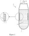
- FIG. 1shows a smart bag/container assembly
- FIG. 2shows an example smart bag electronic circuit layer (or PCB).
- FIG. 3shows a Smart label cross-section assembly
- FIG. 4shows a cross-sectional view of an example smart label printed circuit board (PCB) including an RFID tag.
- PCBprinted circuit board
- FIG. 5shows an example Smart Overwrap Bag.
- FIG. 6shows an example temperature sensing module that can be included in an overlap bag, such as the one shown in FIG. 5 .
- FIG. 7shows the side view of an example thawing cushion device.
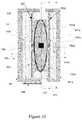
- FIG. 8shows another view of an example cushion device 80 .
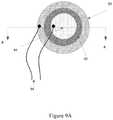
- FIG. 9Ashows a radial view of an example Sonic Vibrator Assembly.
- FIG. 9Bshows a cross-sectional view of an example Sonic Vibrator Assembly.
- FIG. 10shows the top view of the dry heat thawing chamber.
- FIG. 11illustrates the side view of the dry heat thawing chamber.
- FIG. 12shows an implementation where a thawing chamber is used to thaw a bag without an integrated sensor or RF device.
- FIG. 13is a block diagram of a device comprising two typical dry heat thawing chambers (top view).
- FIG. 14is a block diagram of an expanded device from two to four thawing chambers (top view).
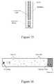
- FIG. 15shows a schematic of an example resistance temperature detector (RTD).
- RTDresistance temperature detector
- FIG. 16shows a schematic of an example nondispersive infrared gas sensor.
- FIG. 17shows a schematic of an example chemical based carbon dioxide sensor.
- FIG. 18shows a block diagram of an example closed-loop system.
- Section Adiscusses a smart bag for containing the biological substances.
- Section Bdiscusses a smart-label that can be affixed to a bag containing biological substances.
- Section Cdiscusses overwrap bags that can be utilized to enclose other bags containing biological substances.
- Section Calso discusses dry thawing chambers used for thawing bags, and modular dry thawing systems including multiple thawing chambers.
- Radio-frequency identificationRFID
- Radio-frequency identificationis the wireless non-contact use of radio-frequency electromagnetic fields to transfer data, for the purposes of automatically identifying and tracking tags attached to objects.
- a RFID systemuses tags, or labels attached to the objects to be identified. These tags contain information that is stored in memory. Two-way radio transmitter-receivers called interrogators or readers send a signal to the tag and read its response.
- RFID tagscan be passive, active or battery-assisted passive.
- An active taghas an on-board battery and periodically transmits its ID signal.
- a battery-assisted passive (BAP)has a small battery on board and is activated when in the presence of a RF reader.
- a passive taghas no battery and must be powered by and read at short ranges via magnetic fields (electromagnetic induction) from an external source (i.e., a RF reader antenna).
- tagsthen act as a passive transponder to emit microwaves or UHF radio waves (i.e., electromagnetic radiation at high frequencies), which the RF reader picks up and interprets as meaningful data.
- Passive tagsmust be illuminated with a power level roughly three magnitudes stronger than for signal transmission.
- RFID tagscan include an integrated circuit (IC) for storing and processing information, modulating and demodulating a radio-frequency (RF) signal, collecting DC power from the incident reader signal, and other specialized functions; and an antenna for receiving and transmitting the signal.
- ICintegrated circuit
- RFradio-frequency
- the tag's componentsare enclosed within plastic, silicon or glass.
- the RFID tagincludes either a chip-wired logic or a programmed or programmable data processor for processing the transmission and sensor data, respectively.
- Tagsmay either be read-only, having a factory-assigned serial number that is used as a key into a database, or may be read/write, where object-specific data can be written into the tag by the system user.
- Field programmable tagsmay be write-once, read-multiple. Data stored on RFID tags can be changed, updated and locked.
- An RFID readertransmits an encoded radio signal to interrogate the tag.
- the RFID tagreceives the message and then responds with its identification and other information. Signaling between the reader and the tag is done in several ways, depending on the frequency band used by the tag.
- Tags operating on LF and HF bandsare, in terms of radio wavelength, very close to the reader antenna because they are only a small percentage of a wavelength away. In this near field region, the tag is closely coupled electrically with the transmitter in the reader.
- the tagcan modulate the field produced by the reader by changing the electrical loading the tag represents. By switching between lower and higher relative loads, the tag produces a change that the reader can detect.
- the RFID tagcan be affixed to an object and can be read if passed near a reader, even if it is covered by the object or not visible.
- the tagcan be read inside a case, carton, box or other container, and unlike barcodes, RFID tags can be read hundreds at a time.
- passive tagshave low production costs and are manufactured to be disposable, along with the disposable consumer goods on which they are placed.
- Temperature sensorsare devices used to measure the temperature of a medium by assessing some physical property which changes as a function of temperature (e.g., volume of a liquid, current through a wire).
- a commonly used temperature sensoris the resistance temperature detector (RTD).
- RTDsprovide an electrical means of temperature measurement, and utilize the relationship between electrical resistance and temperature, which may be linear or nonlinear.
- FIG. 15shows a schematic of an example resistance temperature detector.
- the RTDcontains an outer sheath to prevent contamination from the surrounding medium.
- This sheathcan be composed of material that efficiently conducts heat to the resistor, but resists degradation from heat or the surrounding medium.
- RTD sensorsThere are several categories of RTD sensors, such as, but not limited to: carbon resistors, film thermometers, wire-wound thermometers and coil elements. Sensors are most commonly composed of metals, such as platinum, nickel, or copper. The material chosen for the sensor determines the range of temperatures in which the RTD could be used. For example, platinum sensors, the most common type of resistor, have a range of approximately ⁇ 200° C. to 800° C. Connected to the sensor are two insulated connection leads. These leads continue to complete the resistor circuit.
- thermistorscan be utilized as a temperature sensor.
- Thermistorscan use a semiconductor, ceramic or polymer sensor, and can operate based upon the relationship between electrical resistance or these materials and the temperature.
- thermistorscan exhibit high thermal sensitivity.
- Thermistorscan be classified into two types: a positive temperature coefficient (PTC) thermistor, where the resistance increases with increasing temperature and a negative temperature coefficient (NTC) thermistor, where the resistance decreases with increasing temperature.
- PTCpositive temperature coefficient
- NTCnegative temperature coefficient
- NTC thermistorsare used mostly in temperature sensing and are made from a pressed disc, rod, plate, bead or cast chip of a semiconductor such as a sintered metal oxide. They work because raising the temperature of a semiconductor increases the number of active charge carriers in the conduction band. The more charge carriers that are available, the more current a material can conduct. The measurable electrical current can be sent to the microcontroller via a sensor interface circuitry. The microcontroller can process the received temperature readings into digital signals or values. The microcontroller may store and/or transmit these digital signals or values.
- a pH sensoris a device that measures the concentration of hydrogen ions in an aqueous solution.
- a liquidwould be classified as acidic, alkaline or neutral according to its pH value.
- a pH measurement loopis made up of three components: the pH sensor; a preamplifier; and an analyzer or transmitter.
- a pH sensoris a potentiometric or electrochemical sensor that has a voltage output and consists of a measuring (glass) electrode, a reference electrode and a temperature sensor.
- the measuring electrodewhich is sensitive to the presence of hydrogen ions, develops a potential (voltage) directly related to the hydrogen ion concentration of the solution.
- the reference electrodeprovides a stable potential against which the measuring electrode can be compared.
- a pH measurement loopis essentially a battery where the positive terminal is the measuring electrode and the negative terminal is the reference electrode.
- the pH sensor componentsare usually combined into one device called a combination pH electrode.
- the measuring electrodeis usually glass. Recent developments have replaced glass with more durable solid-state sensors. Additionally, the output of the measuring electrode changes with temperature even though the process remains at a constant pH. Thus a temperature sensor is necessary to correct for this change in output, and such calibration is accomplished via the analyzer or transmitter software.
- the preamplifieris a signal-conditioning device which takes the high-impedance pH electrode signal and changes it into a low impedance signal which the analyzer or transmitter can accept. The preamplifier also strengthens and stabilizes the signal, making it less susceptible to electrical noise. The sensor's electrical signal is then displayed via an analyzer or transmitter. The measurable electrical current can be sent to a microcontroller via a sensor interface circuitry.
- the microcontrollercan process the received pH readings into digital signals or values.
- the microcontrollermay store and/or transmit these digital signals or values.
- the analyzer or transmittercan include a man-machine interface for calibrating the sensor and configuring outputs and alarms, if the pH is being regulated.
- a glucose sensoris a device that measures the approximate concentration of glucose in a blood sample.
- a consumable element containing chemicals that react with blood glucoseis used for each measurement.
- this elementis a plastic test strip with a small spot(s) impregnated with glucose oxidase, which catalyzes the oxidation of glucose to gluconolactone.
- the consumable elementis a plastic test strip with a small spot(s) impregnated with glucose dehydrogenase (GDH), which oxidizes D-glucose to D-glucono-1,5-lactone.
- GDHglucose dehydrogenase
- the glucose sensorsuse an electrochemical method.
- Test stripscontain a capillary that retrieves a reproducible amount of blood.
- the glucose in the bloodreacts with an enzyme electrode containing glucose oxidase (or glucose dehydrogenase).
- the enzymeis reoxidized with an excess of a mediator reagent, such as a ferricyanide ion, a ferrocene derivative or osmium bipyridyl complex.
- the mediatorin turn is reoxidized by reaction at the electrode, which generates an electrical current.
- the total charge passing through the electrodeis proportional to the amount of glucose in the blood that has reacted with the enzyme.
- Some sensorsemploy the coulometric method which measures the total amount of charge generated by the glucose oxidation reaction over a period of time.
- Other glucose sensorsuse the amperometric method which measures the electrical current generated at a specific point in time by the glucose reaction. Both methods give an estimation of the concentration of glucose in the initial blood sample.
- the measurable electrical currentcan be sent to the microcontroller via a sensor interface circuitry.
- the microcontrollercan process the received glucose levels into digital signals or values.
- the microcontrollermay store and/or transmit these digital signals or values.
- a CO 2 sensoris a device that measures the concentration of carbon dioxide gas. Most CO 2 sensors fall into one of two categories: nondispersive infrared gas sensors (NDIR) and chemical based gas sensors.
- NDIRnondispersive infrared gas sensors
- chemical based gas sensorschemical based gas sensors
- FIG. 16shows a schematic of an example nondispersive infrared gas sensor.
- NDIR sensorsare spectroscopic sensors used to detect CO 2 in a gaseous environment. These types of sensors consist of a tube or a chamber in which a source of infrared light is placed at one end and a detector at the other end. CO 2 gas is pumped or diffuses into the tube and the source directs the infrared waves of light in the tube filled with gas. The carbon dioxide molecules absorb light of a particular wavelength. An optical filter which is placed immediately in front of the detector absorbs the light except for the wavelength of light absorbed by carbon dioxide molecules. The difference between the amount of Infrared light at the source and the detector is measured by the electronics. This difference is directly proportional to the number of carbon dioxide molecules present in the gas. The microcontroller can process the received CO 2 levels into digital signals or values. The microcontroller may store and/or transmit these digital signals or values. NDIR CO 2 sensors can also be used for detecting dissolved CO 2 by coupling them to an ATR (attenuated total reflection) optic and measuring the gas in situ.
- ATRat
- FIG. 17shows a schematic of an example chemical based carbon dioxide sensor.
- the basic principle of chemical based carbon dioxide sensorsis the measurement of the pH change of the electrolyte solution caused by the hydrolysis of the CO 2 .
- the chemical based sensorconsists of an oxide electrode, a reference electrode, a bicarbonate-based internal electrolyte solution, and a gas permeable membrane at the bottom of the sensor.
- the CO 2 molecules present in the solutiondiffuse through the gas permeable membrane and enter into the internal electrolyte solution.
- the carbon dioxide moleculesreact with the water to form carbonic acid, which again breaks into bicarbonate and proton ions.
- the measurable electrical currentcan be sent to the microcontroller via a sensor interface circuitry.
- the microcontrollercan process the received CO 2 levels into digital signals or values.
- the microcontrollermay store and/or transmit these digital signals or values.
- An O 2 sensoris a device that measures the concentration of oxygen in the gas or liquid being analyzed.
- the Clark-type electrodeis the most used oxygen sensor for measuring oxygen dissolved in a liquid.
- the basic principleis that there is a cathode and an anode submersed in an electrolyte.
- Oxygenenters the sensor through a permeable membrane (e.g., Teflon) by diffusion, and is reduced at the cathode, creating a measurable electrical current.
- the relationship between the oxygen concentration and the electrical currentis linear.
- the measurable electrical currentcan be sent to the microcontroller via a sensor interface circuitry.
- the microcontrollercan process the received O 2 levels into digital signals or values.
- the microcontrollermay store and/or transmit these digital signals or values.
- An electrical conductivity sensoris a device that measures the ability of a solution to transfer (conduct) electric current.
- Conductivityis the reciprocal of electrical resistivity (ohms) and is therefore used to measure the concentration of dissolved solids which have been ionized in a polar solution.
- conductivity sensorsemploy a potentiometric method which is based on induction.
- the potentiometric methodemploys four concentrically arranged electrodes: the outer two rings apply an alternating voltage and induce a current loop in the solution while the inner rings measure the voltage drop induced by the current loop. This measurement is directly dependent upon the conductivity of the solution. A shield around the rings maintains a constant field by fixing the volume of solution around the rings.
- the electrodesare cylindrical and made of platinum metal. In other embodiments, the electrodes are made of stainless steel. While conductivity could theoretically be determined using the distance between the electrodes and their surface area using Ohm's law, a calibration using electrolytes of well-known conductivity is usually performed.
- a toroidal sensorlooks like a donut (toroid) on a stick and uses two toroidal transformers which are inductively coupled side by side and encased in a plastic sheath.
- a controllersupplies a high frequency reference voltage to the first toroid or drive coil which generates a strong magnetic field.
- the liquid containing conductive ionspasses through the hole of the sensor, it acts as a one turn secondary winding.
- the passage of this fluidthen induces a current proportional to the voltage induced by the magnetic field.
- the conductance of the one turn windingis measured according to Ohm's law.
- the conductanceis proportional to the specific conductivity of the fluid and a constant factor determined by the geometry and installation of the sensor.
- the second toroid or receiving coilis also affected by the passage of the fluid in a similar fashion.
- the liquid passing through the second toroidalso acts as a liquid turn or primary winding in the second toroidal transformer.
- the current generated by the fluidcreates a magnetic field in the second toroid.
- the induced current from the receiving coilis measured as the output of the sensor.
- the controllerconverts the signal from the sensor to specific conductivity of the process liquid.
- the measurable electrical currentcan be sent to the microcontroller via a sensor interface circuitry.
- the microcontrollercan process the received electrical conductivity into digital signals or values.
- the microcontrollermay store and/or transmit these digital signals or values.
- Hermeticityis the process by which the internal environment of the critical components is made secure from invasion and contamination from the external environment, and is a function of both the bulk permeability of the chosen materials and the seal quality.
- the degree and measure of hermeticityis a function of materials choice, final seal design, fabrication processes and practices, and the use environment.
- enclosurescan span a large range of materials and involve numerous joining processes.
- Materialsinclude metals such as nitinol, platinum, or MP35N or other stainless steels, and thin layers of metals such as nickel, gold, and aluminum.
- Other materialsmay include glass, ceramics (Al 2 O 3 ), conductive epoxies, conformal coatings, silicones, Teflon and many plastics—for example, polyurethanes, silicones, and perfluorinated polymers.
- joining processesvary from the use of adhesive sealants and encapsulants to fusion methods such as laser-beam welding or reflow soldering, or solid-state processes such as diffusion bonding.
- Plastics and laminatescan be joined by a variety of methods including but not limited to impulse, heated-platen, radio-frequency (RF), dielectric, and ultrasonic sealing.
- RFradio-frequency
- FIG. 1shows a smart bag/container assembly 10 .
- the smart bag 1includes a smart bag body 1 , a smart bag cover 2 , a smart bag inlet 2 a , an electronic circuit layer 4 and a non-conductive heat-isolation layer 5 .
- the Smart bag or container 1 of the present technologycan be soft, semi-rigid or rigid and can be made from materials such as plastic, metal thin sheet, or other materials and/or a combination thereof.
- the cover 2 of the Smart bag or containeris hermetically sealed to protect its contents 3 .
- the hermetic sealis composed of biologically inert material (e.g., epoxy).
- the hermetically sealed cover 2 of the Smart bag or containercontains an inlet 2 a , wherein the inlet can be a valve, mechanical stopper, a spigot, or a plug.
- FIG. 1shows an implementation where the cover 2 of the Smart bag 10 contains an inlet 2 a .
- the inlet 2 aensures the sterile transfer of biological substances into and out of the Smart bag 10 .
- the Smart bag or container 10is low-cost and disposable after a single use.
- the Smart bag 10can accommodate any volume of biological substances and can function in a wide ambient temperature range ( ⁇ 196° C. to +40° C.).
- the biological substancesare fresh, frozen, stored or thawed and are selected from the group consisting of medication, plasma, whole blood, glycerolized blood, and RBCs.
- FIG. 1shows an implementation where a heat-isolation, nonconductive layer 5 can be printed on specific areas of the inner wall of the Smart bag 10 . As shown in FIG.
- an RFID tag containing an electronic circuit layer 4(also known as a printed circuit board (PCB)) is printed or glued on the inner side of the heat-isolation, nonconductive layer 5 such that an attached sensor (e.g., temperature sensor, pH sensor, glucose sensor, oxygen sensor, carbon dioxide sensor, conductivity sensor) will be facing the opposite direction and is in direct contact with the fresh, frozen, stored or thawed biological substance 3 contained within the bag 10 .
- Biological substancescan be selected from the group consisting of medication, plasma, whole blood, glycerolized blood, and RBCs.
- the heat-isolation, nonconductive layer 5helps reduce the impact of the ambient temperature on the readings of the RFID tag.
- the on-board electronics of the PCBare powered by electromagnetic induction from a RF reader antenna.
- FIG. 2shows an example smart bag electronic circuit layer (or PCB) 20 .
- the PCB layer 20includes an RFID tag 21 communicably coupled to a sensor assembly 25 that can measure the physiological and/or physical parameters of biological substances contained within the Smart bag 10 shown in FIG. 1 .
- the RFID tag-sensor couplingis achieved by integrating electronic components such as universal signal acquisition circuits (which read and acquire sensors data) on the PCB layer 20 .
- the PCB layer 20can further include power interface circuitry 22 a for receiving power from an RFID reader.
- the power interface circuitrycan be coupled to an RF reader antenna 22 and harvest power from the voltage induced in the antenna 22 due to an RF signal received from the RF reader.
- the power interface circuitry 22 acan include a rectifier for rectifying the A/C voltage appearing across the antenna into a D/C voltage.
- the power interface circuitry 22 amay also include voltage step-up and voltage step-down circuitry for providing the desired voltages to various components on the PCB layer 20 .
- the power interface circuitry 22 acan be used to provide power to all the other circuitry included in the RFID tag 21 , for example, the sensors, microcontrollers, memory, any interface circuitry, etc.
- the PCB 20can be coupled to a battery to receive power in addition to or instead of receiving power as a result of an RF signal received from the RF reader.
- the PCB 20can also include a microcontroller or a microprocessor 23 for receiving and processing the sensor data received from the sensors 25 (e.g., temperature sensor, pH sensor, glucose sensor, oxygen sensor, carbon dioxide sensor, conductivity sensor etc., discussed above).
- the microcontroller 23can also be utilized for carrying out communications with the external RFID reader.
- the microcontroller 23can include a memory for storing executable instructions for processing and storing sensor data, for communicating with the external RF reader, etc.
- the memorycan include nonvolatile memory configured to store sensed parameters associated with biological substances enclosed within Smart bags, and acquisition circuitry.
- the physiological parameterscan include temperature, pH, conductivity, glucose, O 2 , and CO 2 levels and the physical parameters can include identification, source history, demographic data and time stamping.
- the microcontroller or microprocessor 23can be implemented using FPGAs (field-programmable gate arrays) or ASICs (application-specific integrated circuits).
- a sensor interface circuitry 24can be provided for the microcontroller 23 to interface with the sensor 25 .
- the sensor interface circuitry 24can include an analog-to-digital converter (ADC) for converting analog voltages/currents (representing the measured parameter) output by the sensor 25 into digital data. Such digital data can then be processed, stored, and/or transmitted by the microcontroller 23 .
- the sensor interface circuitry 24can be included within the microcontroller 23 itself.
- the RFID tag 21stores the acquired sensor data in nonvolatile memory and communicates the stored data wirelessly to a RF reader.
- the electronic device of the Smart bagcan include thermistors and/or other temperature sensors (e.g., traditional RTDs) that contact and measure the temperature of the biological substances enclosed within the bag during the thawing process.
- the RFID tag 21 of the Smart bagwill then store the temperature data associated with the enclosed biological substances in nonvolatile memory and will wirelessly communicate the stored data to a RF reader.
- the temperature sensoris a traditional resistance temperature detector (RTD).
- the temperature sensoris a thermistor.
- the thermistoris a negative temperature coefficient (NTC) thermistor.
- the sensor assembly 25can include a pH sensor that measures the pH of the biological substances enclosed within the bag. In some embodiments, the sensor assembly 25 can include a glucose sensor that measures the glucose levels of the biological substances enclosed within the bag. In some embodiments, the glucose sensor uses glucose oxidase as the consumable element for each measurement. In some embodiments, the glucose sensor uses glucose dehydrogenase as the consumable element for each measurement. In some embodiments, the glucose sensor employs the coulometric method. In other embodiments, the glucose sensor employs the amperometric method.
- the sensor assembly 25can include a CO 2 sensor that measures the CO 2 levels of the biological substances enclosed within the bag.
- the CO 2 sensor assembly 25can include a nondispersive infrared gas sensor (NDIR).
- NDIRnondispersive infrared gas sensor
- the CO 2 sensoris a chemical based gas sensor.
- the sensoris an O 2 sensor that measures the O 2 levels of the biological substances enclosed within the bag.
- the O 2 sensoris a Clark-type electrode.
- the sensor assembly 25can include an electrical conductivity sensor that measures the ability of the biological substances enclosed within the bag to transfer (conduct) electric current.
- the electrical conductivity sensoremploys the potentiometric method.
- the electrical conductivity sensoris a toroidal sensor.
- Smart labelrefers to a device that includes one or more sensors configured to measure parameters of bags containing biological substances and a radio-frequency (RF) device (i.e., the RFID tag) communicably coupled to the sensor and configured to: (a) acquire from the sensor parameters associated with bags containing biological substances, (b) store the acquired sensor data in nonvolatile memory, and (c) communicate the stored data wirelessly to a RF reader.
- RFradio-frequency
- the label or encapsulated thin container of the present technologycan be soft, semi-rigid or rigid and can be made from materials such as plastic, metal thin sheet, or other materials and/or a combination thereof.
- the labelis hermetically sealed.
- the hermetic sealcan be composed of biologically inert material (e.g., epoxy).
- the labelcan be low-cost and disposable after a single use.
- Hermeticityis the process by which the internal environment of the critical components is made secure from invasion and contamination from the external environment, and is a function of both the bulk permeability of the chosen materials and the seal quality.
- the degree and measure of hermeticityis a function of materials choice, final seal design, fabrication processes and practices, and the use environment.
- enclosurescan span a large range of materials and involve numerous joining processes.
- Materialsinclude metals such as nitinol, platinum, or MP35N or other stainless steels, and thin layers of metals such as nickel, gold, and aluminum.
- Other materialsmay include glass, ceramics (Al 2 O 3 ), conductive epoxies, conformal coatings, silicones, Teflon and many plastics—for example, polyurethanes, silicones, and perfluorinated polymers.
- joining processesvary from the use of adhesive sealants and encapsulants to fusion methods such as laser-beam welding or reflow soldering, or solid-state processes such as diffusion bonding.
- Plastics and laminatescan be joined by a variety of methods including but not limited to impulse, heated-platen, radio-frequency (RF), dielectric, and ultrasonic sealing.
- RFradio-frequency
- FIG. 3shows a cross-sectional view of an implementation where a Smart label 30 can be affixed to an outer wall of a bag (not shown) containing biological substances.
- an adhesive layer 36is located on the same side as a temperature sensor 35 .
- the adhesive layer 36allows the smart label 30 to be affixed to the outer wall of the bag.
- the adhesive layer 36 and the temperature sensor 35are located on opposite sides, thus allowing the Smart label 30 to be affixed to the inner wall of a bag containing biological substances.
- the bag containing the biological substancescan be of any size.
- the biological substancesare fresh, frozen, stored or thawed and are selected from the group consisting of medication, plasma, whole blood, glycerolized blood, and RBCs.
- FIG. 3shows an implementation where the side of the Smart label 30 , which interfaces with the ambient environment, is covered by a heat-isolation, nonconductive layer 32 .
- the heat-isolation, nonconductive layer 32helps reduce the impact of the ambient temperature on the readings of the Smart label 30 .
- the Smart Label 30can include an RFID tag composed of a printed circuit board (PCB) 34 that is printed or glued on the inner side of the heat-isolation, nonconductive layer 32 such that an attached sensor (e.g., temperature sensor) 35 will be facing the opposite direction and is in contact with the bag or enclosure containing the fresh, frozen, stored or thawed biological substance.
- the biological substancesmay be selected from the group consisting of medication, plasma, whole blood, glycerolized blood, and RBCs.
- the on-board electronics 33 of the PCB 34are powered by electromagnetic induction from a RF reader antenna.
- FIG. 4shows a cross-sectional view of an example smart label printed circuit board (PCB) 40 including an RFID tag 41 .
- the PCB 40can be used to implement the PCB 34 shown in FIG. 3 .
- the PCB 40can be affixed to an outer wall 46 of a bag containing biological substances. In some implementations, the PCB 40 can be instead affixed to an inner wall of the bag.
- the RFID tag 41is communicably coupled to a sensor 35 (also shown in FIG. 3 ) that can measure the physiological and/or physical parameters of bags containing biological substances.
- the RFID tag-sensor couplingis achieved by integrating electronic components such as universal signal acquisition circuits (which read and acquire sensors data) on the PCB layer 40 .
- the PCB 40can further include power interface circuitry 42 for receiving power from an RFID reader.
- the power interface circuitry 42can be coupled to an RF reader antenna 43 and harvest power from the voltage induced in the antenna due to an RF signal received from the RF reader.
- the power interface circuitry 42can include a rectifier for rectifying the A/C voltage appearing across the antenna into a D/C voltage.
- the power interface circuitry 42may also include voltage step-up and voltage step-down circuitry for providing the desired voltages to various components on the PCB 40 .
- the power interface circuitrycan be used to provide power to all the other circuitry included in the RFID tag 41 , for example, the sensors, microcontrollers, memory, any interface circuitry, etc.
- the PCB 40can be coupled to a battery to receive power in addition to or instead of receiving power as a result of an RF signal received from the RF reader.
- the PCB 40can also include a microcontroller or a microprocessor 44 for receiving and processing the sensor data received from the sensors 35 (e.g., temperature sensor).
- the microcontroller 44can also be utilized for carrying out communications with the external RFID reader.
- the microcontroller 44can include a memory for storing executable instructions for processing and storing sensor data, for communicating with the external RF reader, etc.
- the memorycan include nonvolatile memory configured to store sensed parameters associated with bags containing biological substances, and acquisition circuitry.
- the physiological parameterscan include temperature and the physical parameters can include identification, source history, demographic data and time stamping.
- the microcontroller or microprocessor 44can be implemented using FPGAs (field-programmable gate arrays) or ASICs (application-specific integrated circuit).
- a sensor interface circuitry 44 acan be provided for the microcontroller 44 to interface with the sensor 35 .
- the sensor interface circuitry 44 acan include an analog-to-digital converter (ADC) for converting analog voltages/currents (representing the measured parameter) output by the sensor into digital data. Such digital data can then be processed, stored, and/or transmitted by the microcontroller 44 .
- the sensor interface circuitry 44 acan be included within the microcontroller 44 itself.
- the RFID tag 41stores the acquired sensor data in nonvolatile memory and communicates the stored data wirelessly to a RF reader.
- the Smart labelcomprises of thermistors and/or other temperature sensors (e.g., traditional RTDs) that contact and measure the temperature of bags containing biological substances during the thawing process.
- the RFID tag 41 of the Smart labelwill then store the temperature data associated with the bags containing biological substances in nonvolatile memory and will wirelessly communicate the stored data to a RF reader. Because the RFID tag of the Smart label facilitates accurate temperature sensing of bags containing biological substances, the dangers of overheating and/or underheating during the thawing process are minimized.
- the temperature sensoris a traditional resistance temperature detector (RTD).
- the temperature sensoris a thermistor.
- the thermistoris a negative temperature coefficient (NTC) thermistor.
- FIG. 5shows and example Smart overwrap bag 50 .
- the Smart overwrap bag 50can be composed of materials having high thermal conductivity such as plastic, metal thin sheet, other known thermal conductors, and/or a combination thereof, and can function in a wide ambient temperature range ( ⁇ 196° C. to +40° C.).
- the Smart overwrap bag 50can be routinely used to enclose and protect bags 53 containing biological substances from microbial contamination during the thawing process. In the event that the bag 53 containing biological substances leaks or breaks during the thawing process, the overwrap bag 50 isolates the biological contents, thereby preventing them from contaminating the thawing device or system.
- the overwrap bag 50can enclose a bag containing biological substances of any size (e.g., 250-500 ml).
- the overwrap bag 50can be soft, semi-rigid or rigid and its cover can hermetically sealed to protect its contents.
- the hermetic sealis composed of biologically inert material (e.g., epoxy).
- an engaging mechanism at the opening of the overwrap bag 50may be used to remove the bag containing biological substances after the thawing process is complete.
- FIG. 5shows an implementation where the engaging mechanism at the opening of the overwrap bag is a ziplock 52 .
- the overwrap bag 50can be low-cost and can be disposable after a single use.
- the overlap bag 50can have high thermal conductivity.
- the high thermal conductivity of the overwrap bag 50can facilitate rapid thawing of the enclosed bags 53 containing biological substances.
- a dry thawing methodcan be used for thawing the enclosed bag 53 .
- conventional water-bath or water bladder methodscan also be used.
- mechanical agitationcan be used during the thawing method to achieve a homogenous temperature profile within the enclosed bag 53 containing biological substances and to prevent damage to the biological substances.
- the biological substancescan be fresh, frozen, stored or thawed and can include medication, plasma, whole blood, glycerolized blood, and RBCs.
- the overlap bag 50can include one or more temperature sensing modules 54 for sensing the temperature of the enclosed bag 53 .
- FIG. 6shows an example temperature sensing module 54 that can be included in an overlap bag, such as the one shown in FIG. 5 .
- the temperature sensing module 54can be similar to the Smart label 30 discussed above in relation to FIG. 3 .
- the temperature sensing module 54can include a heat-conductive layer 56 , an electronic circuit 57 , and a temperature sensor 58 .
- the heat-nonconductive layer 56can be printed or disposed on specific areas of an inner wall 59 of the overwrap bag.
- the inner wall 59 of the overlap bagcan also be in contact with the outer wall of the enclosed bag containing biological substances (such as the enclosed bag 53 shown in FIG. 5 ). According to FIGS.
- an RFID tag containing an electronic circuit layer(or a printed circuit board (PCB)) is printed or glued on the inner side of the heat-nonconductive layer such that an attached sensor (e.g., temperature sensor) will be facing the opposite direction and is in contact with the bag containing the fresh, frozen, stored or thawed biological substance.
- Biological substancescan be selected from the group consisting of medication, plasma, whole blood, glycerolized blood, and RBCs.
- the heat-nonconductive layerhelps reduce the impact of the ambient temperature on the readings of the RFID tag.
- the on-board electronics of the PCBare powered by electromagnetic induction from a RF reader antenna. As shown in FIG.
- the RFID tagis communicably coupled to a sensor that will measure the physiological and/or physical parameters of the enclosed bags containing biological substances.
- the RFID tag-sensor couplingis achieved by integrating electronic components such as universal signal acquisitions (which read and acquire sensor data) on the PCB layer.
- the PCBcan further include power interface circuitry for receiving power from the RFID reader.
- the power interface circuitrycan be coupled to the RF reader antenna and harvest power from the voltage induced in the antenna due to an RF signal received from the RF reader.
- the power circuitrycan include a rectifier for rectifying the A/C voltage appearing across the antenna into a D/C voltage.
- the power circuitrymay also include voltage step-up and voltage step-down circuitry for providing the desired voltages to various components on the PCB.
- the power circuitrycan be used to provide power to all the other circuitry included in the RFID tag, for example, the sensors, microcontrollers, memory, any interface circuitry, etc.
- the PCBcan be coupled to a battery to receive power in addition to or instead of receiving power as a result of an RF signal received from the RF reader.
- the PCBcan also include a microcontroller or a microprocessor for receiving and processing the sensor data received from the sensors (e.g., temperature sensor).
- the microcontrollercan also be utilized for carrying out communications with the external RFID reader.
- the microcontrollercan include a memory for storing executable instructions for processing and storing sensor data, for communicating with the external RF reader, etc.
- the memorycan include nonvolatile memory configured to store sensed parameters associated with enclosed bags containing biological substances during the thawing process, and acquisition circuitry.
- the physiological parameterscan include temperature and the physical parameters can include identification, source history, demographic data and time stamping.
- the microcontroller or microprocessorcan be implemented using FPGAs (field-programmable gate arrays) or ASICs (application-specific integrated circuits).
- a sensor interface circuitrycan be provided for the microcontroller to interface with the sensor.
- the sensor interface circuitrycan include an analog-to-digital converter (ADC) for converting analog voltages/currents (representing the measured parameter) output by the sensor into digital data. Such digital data can then be processed, stored, and/or transmitted by the microcontroller.
- ADCanalog-to-digital converter
- the sensor interface circuitrycan be included within the microcontroller itself.
- the RFID tagstores the acquired sensor data in nonvolatile memory and communicates the stored data wirelessly to a RF reader.
- the electronic device of the overwrap bagcomprises of thermistors and/or other temperature sensors (e.g., traditional RTDs) that contact and measure the temperature of enclosed bags containing biological substances during the thawing process.
- the RFID tag of the overwrap bagwill then store the temperature data associated with the enclosed bags containing biological substances in nonvolatile memory and will wirelessly communicate the stored data to a RF reader. Because the RFID tag facilitates accurate temperature sensing of the enclosed bags containing biological substances, the dangers of overheating and/or underheating during the thawing process are minimized.
- the temperature sensoris a traditional resistance temperature detector (RTD).
- the temperature sensoris a thermistor.
- the thermistoris a negative temperature coefficient (NTC) thermistor.
- the RFID tagmay be implemented on a system-on-chip (SOC). In some other implementations, the RFID tag may be implemented using discrete components.
- SOCsystem-on-chip
- a Smart labelsimilar to the Smart label 30 discussed above in relation to FIG. 3 can be utilized as a sensing module within the overlap bag 50 shown in FIG. 5 .
- FIG. 7shows a side view of an example dry thawing cushion device 70 .
- the cushion deviceincludes a flexible non-heat conducting layer, i.e., the cushion 71 that is affixed to a sonic vibrator assembly 76 on its outer side, and a printed circuit board (not shown) on its inner side.
- the printed circuit board on the inner side of the cushioninterfaces with a heating element 72 and one or more temperature sensors 75 .
- the heating element 72is attached to a flexible heat conducting sheet 73 , the flexible heat conducting sheet 73 being configured to come into contact with a bag containing biological substances.
- FIG. 10shows one or more temperature sensors 75 placed in or around the center on the inner side of the cushion, which are configured to (a) make contact with the bag in need of thawing and (b) periodically measure the temperature of the bag during the thawing process.
- the temperature sensor 75can be a traditional resistance temperature detector (RTD).
- the temperature sensorcan be a thermistor.
- the thermistorcan be a negative temperature coefficient (NTC) thermistor.
- the cushion device 70can include two cushion devices facing each other, such that the two cushion devices can thaw a bag containing biological substances.
- the two cushion devicescan have dimensions that are configured to contact a standard 250 ml-500 ml bag containing medication, plasma, whole blood, glycerolized blood bag, RBCs and/or other biological substances. Additionally, the flexible nature of the cushion materials ensure that bags or containers for biological substances of larger sizes can be accommodated within the space between the two flexible heat conducting sheets of the first and second cushion devices.
- the cushion 71can be composed of materials that have low thermal conductivity, and can include, without limitation, materials such as polystyrene foam, starch-based foams, cellulose, paper, rubber, non-woven material, and plastic. As seen in FIGS. 7 and 14 , the cushion 71 insulates the sonic vibrator 76 assembly and temperature sensor 75 from the thermal energy generated by the heating element 72 .
- the cushion 71thus serves a dual purpose: protecting the sonic vibrator assembly 76 and temperature sensor 75 from thermal damage and facilitating efficient unidirectional heat transfer from the heating element 72 to the flexible heat conducting sheet 73 to the bag of biological substances that requires thawing.
- the heating element 72 located between the cushion 71 and the flexible heat conducting sheet 73is a high density, low-power heating element.
- the flexible heat conducting sheet 73is thin and composed of silicon or other materials with similar thermal conductivity properties.
- FIG. 16shows an implementation where the flexible heat conducting sheet is transparent. In other implementations, the flexible heat conducting sheet is opaque or translucent.
- the temperature sensor 75is placed in clearance of the flanking heat element 72 and the flexible heat conducting sheet 73 in order to prevent thermal damage to the sensor 75 .
- the temperature sensor 75can be also mounted on and surrounded by heat insulation barriers 74 with the above clearance dimensions. The presence of the heat insulation barriers 74 can minimize the impact of the heating element 72 and flexible heat conducting sheet 73 on the temperature sensor 75 readings.
- the heat insulation barriers 74are composed of materials including, but not limited to polystyrene foam, starch-based foams, cellulose, paper, rubber, non-woven material, wood, plastic and tin foil.
- the sonic vibrator assembly 76discussed below generates low frequency (10 Hz-50 Hz) vibrations to achieve homogenous thawing within the bag containing biological substances. These low frequency vibrations are barely perceptible to the human ear, thereby circumventing the need to use audible mechanical moving mechanisms that cause noise. As shown in FIG. 7 , the sonic vibrator assembly 76 is affixed to the outer side of the cushion 71 .
- the sonic vibrator assembly 76includes, among others, the following components: two electrodes, a piezoceramic disc, and wire leads.
- Piezoelectric materialssuch as, for example, the piezoceramic disc, have the ability to generate a voltage in response to an applied mechanical stress or conversely change shape in response to an applied voltage.
- the piezoceramic discmay be composed of high power “hard” materials, high sensitivity “soft” materials, or high performance piezoelectric crystals.
- the piezoceramic disc 92is sandwiched between two electrodes ( 91 and 93 ), and lead wires 94 are attached to each electrode ( 91 and 93 ).
- the electrodes 91 and 93are composed of metal.
- the electrodes 91 and 93 of the sonic vibration assembly 76comprise a silver electrode and a brass plate.
- FIGS. 9A and 9Bshow an implementation where one side of the piezoceramic disc 92 is adhered to a brass plate electrode 93 , while the opposite side of the piezoceramic disc 92 is adhered to a silver electrode 91 .
- the brass plate electrode 93is affixed to the flexible non-heat conducting layer, i.e. the cushion 95 .
- the radius of the brass plate electrode 93is larger than that of the piezoceramic disc 92 and the silver electrode 91 .
- the alternating potential difference between the two electrodescauses the piezoceramic disc 92 to mechanically expand or contract in the radial direction at substantially the same frequency as that of the applied alternating voltage signal.
- This resulting radial expansion and contraction of the piezoceramic disc 92causes the brass plate electrode 93 to vibrate with the piezoceramic disc 92 .
- These vibrations in the brass plate electrode 93can, in turn, be transferred to the cushion to which the brass plate electrode 93 is adhered.
- a low frequency alternating signale.g. 10 Hz
- the thickness of the electrode that makes contact with the cushion 95can, in part, affect the amplitude of the vibrations transferred to the cushion.
- the thickness of the brass plate electrode 93 in FIG. 9Branges from about 0.5 mm to about 1 mm. In some implementations, the brass plate electrode 93 in FIG. 9B is 0.5 mm thick. In some implementations, the brass plate electrode 93 in FIG. 9B is 1 mm thick.
- FIG. 8shows another view of an example cushion device 80 .
- the cushion device 80includes a cushion 81 , a high density heating element 82 , a temperature sensor 85 disposed between a heat insulation barrier 84 . Wires from the high density heating element 82 and the temperature sensor 95 affixed into an electronic connector 87 that is configured to connect to a power source (not shown) and a controller (not shown).
- FIGS. 10 and 11show a top view and a side view, respectively, of a dry heat thawing chamber 100 .
- the dry heat thawing chamber 100includes a first side chamber 101 and an adjustable second side chamber 101 a .
- the first side chamber 101includes a first cushion device 103 , a first heating element 102 , a first temperature sensor 104 , a first sonic vibrator assembly 105 , a first heat insulation barrier 107 , a first heat conducting sheet 108 , and a first radio-frequency (RF) reader 106 .
- RFradio-frequency
- the adjustable second side chamber 101 aincludes a second cushion device 103 a , a second heating element 102 a , a second temperature sensor 104 a , a second sonic vibrator assembly 105 a , a second heat insulation barrier 107 a , a second heat conducting sheet 108 a , and a second RF reader 106 a .
- the thawing chamber 100also includes a front end control (FEC) board 109 .
- FIGS. 10 and 11also show an overlap bag 110 containing an enclosed bag 111 .
- the bag 111 containing medication, plasma, whole blood, glycerolized blood, RBCs or any other biological substanceis placed in the space between the two flexible heat conducting sheets 108 and 108 a of the first and second cushion devices 103 and 103 a .
- the high-density heating elements 102 and 102 aproduce thermal energy which diffuses into the flexible heat conducting sheets 108 and 108 a .
- heatis transferred from the flexible heat conducting sheets 108 and 108 a to the bag 111 in need of thawing by conduction. Thermal convective flow may take prominence as the biological substance near the heated walls of the bag 111 becomes liquefied.
- the low frequency vibrations produced by the sonic vibrator assemblies 105 and 105 aprevent concentration gradients from being formed during the thawing process and helps achieve an almost homogenous temperature profile within the bag.
- temperature sensors 104 and 104 ameasure the temperature of the bag 111 and communicate the measurements to a controller via the electronic connector during the thawing process.
- the dry thawing processcan be terminated as soon as the bag 111 containing the biological substance reaches a desired temperature, thereby reducing the risk of overheating, underthawing, and denaturation, and increasing the efficiency of the thawing process.
- a standard 250 ml-500 ml bag containing plasma, whole blood, glycerolized blood bag, and/or other biological substances with a starting temperature of ⁇ 40° C.can be thawed to 36.6° C. within 10 minutes when the cushion device is powered with electrical current.
- a standard 250 ml-500 ml bag containing plasma, whole blood, glycerolized blood bag, and/or other biological substances with a starting temperature of ⁇ 40° C.can be thawed to 36.6° C. within 5 minutes when the cushion device is powered with electrical current.
- the disclosed dry thawing deviceconfers several advantages: (1) reduced risk of microbial contamination compared to thawing methods involving water-baths, (2) uniform thawing of the biological substance resulting in reduced risk of overheating, underthawing or denaturation, (3) low maintenance compared to conventional water baths and water bladders.
- the perimeter of the flexible heat conducting sheets 108 and 108 ais larger than the perimeter of the bag 111 containing the biological substance. In other embodiments, the perimeter of the flexible heat conducting sheets 108 and 108 a is the same as the perimeter of the bag 111 containing biological substances.
- FIG. 13shows a schematic of an example modular dry thawing apparatus 130 .
- FIG. 13shows a main module 132 including two separate thawing chambers 133 .
- Each thawing chamber 133can be implemented using the dry heat thawing chamber 100 discussed above in relation to FIGS. 10 and 11 .
- the main module 132also includes a central controller 135 , a universal power supply 136 , and a graphical user interface or display 137 .
- the central controller 135can include a control program for controlling the thawing chambers 133 .
- the central controllercan receive data received from the RF readers and provide control signals to the thawing chambers 133 .
- the central controller 135can also include expansion ports 138 for connecting auxiliary modules, and include communication ports 139 for providing communication to external devices.
- the power supply 136can receive AC power 136 and provide one or more AC or DC voltages and currents to the various components of the main module 132 (and any auxiliary modules).
- FIG. 14shows a schematic of another modular dry thawing apparatus 140 including at least two modules: a main module 132 and an auxiliary module 132 a .
- the auxiliary module 132 acan be used as an expansion module and connect into and controlled by the main module 132 .
- the auxiliary module 132 acan allow adding capacity to the modular dry thawing apparatus 140 .
- individual thawing chambers 133 of the main module 132 or auxiliary module 132 amay be encompassed within their respective external enclosures.
- the main module 132 of the computerized closed-loop dry thawing system 130has a two chamber configuration.
- the main module 132 of the computerized closed-loop dry thawing systemhas a four chamber configuration.
- the main module 132 of the computerized closed-loop dry thawing systemhas an eight chamber configuration.
- the main module 132can include any number of dry heat thawing chambers 133 .
- a thawing chamber 133is a three-dimensional rectangular compartment that encloses two dry thawing cushion devices.
- the exterior of the thawing chamberis composed of plastic, metal, or a metal alloy (e.g., stainless steel).
- the thawing chamberhas a bacteria-resistant powder coated exterior.
- the dry thawing devicecomprises two cushion devices wherein the heat conducting portion of the first cushion device faces the heat conducting portion of the second cushion device.
- FIG. 14shows an implementation where one of the elongated side walls of the thawing chamber 133 is adjustable.
- the components of the cushion devicei.e., the flexible non-heat conducting layer, flexible heat conducting sheet, heating element, temperature sensor, sonic vibrator assembly, and heat insulation barrier
- the flexible heat conducting sheets of the thawing deviceare also adjustable.
- RF readersare embedded in the interior walls of the thawing chamber 133 .
- Fixed RF readersare set up to create a specific interrogation zone which can be tightly controlled.
- the interrogation zonewould be the space between the two flexible heat conducting sheets of the first and second cushion devices. This designated space acts as a repository for bags that incorporate RFID tags and are used for storing biological substances. This allows a highly defined reading area for when RFID tags go in and out of the interrogation zone.
- each thawing chamber 133can be used for thawing bags such as the smart bag 10 shown in FIG. 1 , the overwrap bag 50 shown in FIG. 5 , and bags having a Smart label discussed above in relation to FIG. 6 .
- the thawing chamber 133also can be used for thawing bags that lack integrated sensors and/or RF devices.
- FIG. 12shows an implementation where a thawing chamber 120 is used to thaw a bag 121 without an integrated sensor or RF device.
- the bag 120is placed on a cushion 122 including a high density heating element 123 .
- the cushion 122can be similar to the cushion device 80 discussed above in relation to FIG. 8 . That is, the cushion 122 can include a temperature sensor for sensing the temperature of the bag 120 , and an RFID for transmitting the sensed temperature to a RF reader.
- the bag 120may also be enclosed in an overlap bag, such as the one discussed above in relation to FIG. 5 .
- the chamber 133can be used for thawing bags that incorporate a sensor configured to measure temperature of the bag and a radio-frequency (RF) device communicably coupled to the sensor and configured to: (a) acquire from the sensor data associated with the measured temperatures, (b) store the acquired sensor data in nonvolatile memory, and (c) communicate the stored temperature data wirelessly to a RF reader (i.e., a Smart Label).
- a RF readeri.e., a Smart Label
- the sensor and the RF deviceare affixed to the outer wall of the bag.
- the sensor and the RF deviceare affixed to the inner wall of the bag.
- the sensors and RF devices affixed to the inner wall of the bagsense and store additional physical and physiological parameters including source history, identification, demographics, time stamping, temperature, pH, conductivity, glucose, O 2 , CO 2 levels, which can subsequently be communicated wirelessly to a RF reader.
- the thawing chamber 133may be used to thaw bags containing biological substances that are enclosed and protected by overwrap bags, one example of which is discussed above in relation to FIG. 5 .
- overwrap bagsincorporate a sensor configured to measure temperature of the enclosed bags containing biological substances and a radio-frequency device communicably coupled to the sensor and configured to: (a) acquire from the sensor data associated with the measured temperatures, (b) store the acquired sensor data in nonvolatile memory, and (c) communicate the stored temperature data wirelessly to a RF reader.
- each thawing chamber 133can include a front end control board 134 that permits direct user-interaction with the thawing chamber 133 .
- the front end control board 134comprises a chamber temperature display, bag temperature display, one or more timer displays, controls for setting or adjusting chamber temperature, a heating status visual indicator, controls for setting or adjusting sonic vibration parameters, and a power switch.
- the sonic vibration controlspermit users to manually input the desired frequency (Hz) and timing of the sonic vibrator assembly.
- the front end control board 134contains controls permitting the user to set a program sequence for sonic vibration and/or temperature modulation.
- the front end control board 134contains controls that permit users to manually start or stop sonic vibration and/or heating at any point during the thawing process. In some implementations, the front end control board 134 contains an audiovisual alarm that indicates when the bag temperature reaches the desired temperature (e.g., 36.6° C.).
- FIG. 18shows a block diagram of an example closed-loop system.
- a closed-loop systemrefers to a system which compares an output variable of a system to a certain reference value and manipulates the inputs of a system to obtain the desired effect on the output of the system.
- the modular dry thawing apparatus 130and in particular the central controller 135 , shown in FIG. 13 can utilize a closed-loop dry thawing method.
- the closed-loop dry thawing methodcan utilize the example closed loop system shown in FIG. 18 .
- temperature sensorsmonitor the system output (temperature) of a bag containing biological substances in each thawing chamber 133 and transmit the data to the central controller 135 .
- the central controller 135then transforms the data and compares it to a preset value, e.g., the desired temperature, and subsequently adjusts the system input (electrical current) as necessary to thaw the bag and achieve the desired temperature.
- the central controlleraffects the temperature of the bag, which in turn is measured and looped back to alter the control.
- the universal power supply 136drives electrical current to all electrical components of the dry thawing apparatus including the sonic vibrator assembly, the high density heating filament, and the built-in temperature sensors of the cushion device, the RF readers of the thawing chambers 133 , the central controller, and the graduated AC/DC power supply.
- the universal power supply 136drives electrical current to the graphic user interface 137 .
- the central controller 135controls all functional aspects of the disclosed dry thawing apparatus 130 and 140 .
- the central controller 135acquires from the temperature sensors of the cushion devices data associated with recurring measured temperatures, transforms and compares the acquired data to the preset temperature value, and generates an error signal by subtracting the sensed value from the preset temperature value.
- the central controller 135then responds to the generated error signal by regulating the electrical current supplied to the high density heating elements in a particular thawing chamber 133 until the bag achieves the preset temperature value.
- the central controller 135can also adjust the electrical current supplied to the high density heating elements in a given thawing chamber 133 based on input that is manually entered by the user.
- user inputcan be directly entered into the central controller 135 .
- user inputcan be entered through a remote device that is linked to the central controller 135 via a LAN/WAN Wifi network 136 a .
- the central controller 135communicates with the graduated AC/DC power supply 136 to regulate the electrical current supplied to a thawing chamber 133 .
- the central controller 135will automatically shut off electrical power to flexible heat conducting sheets within a particular thawing chamber 133 once the bag containing biological substances reaches the desired temperature.
- the central controller 135will trigger an audio and/or visual alarm chamber once the bag containing biological substances reaches the desired temperature.
- the central controller 135is also communicably coupled to RF readers that are embedded in the interior walls of the thawing chamber 133 . This feature permits the central controller 135 to read and interpret any data acquired from RFID tags that are affixed to overwrap bags or bags containing biological substances (i.e., bags including Smart Labels) in the thawing chamber 133 .
- the central controlleracquires from the RF readers data associated with recurring measured temperatures, transforms and compares the acquired data to the preset temperature value, and generates an error signal by subtracting the sensed value from the preset temperature.
- the central controllerthen responds to the generated error signal by regulating the electrical current supplied to the high density heating elements in a particular thawing chamber 133 until the bag achieves the preset temperature value.
- the central controller 135can also adjust the electrical current supplied to the high density heating elements in a given thawing chamber 133 based on input that is manually entered by the user.
- user inputcan be directly entered into the central controller 135 .
- user inputcan be entered through a remote device that is linked to the central controller via a LAN/WAN Wifi network.
- the central controller 135communicates with the graduated AC/DC power supply 136 to regulate the electrical current supplied to a thawing chamber.
- the central controller 135will automatically shut off electrical power to flexible heat conducting sheets within a particular thawing chamber once the bag containing biological substances reaches the desired temperature.
- the central controller 135also displays sensor output on a graphic user interface (GUI) 137 .
- GUIgraphic user interface
- the GUI 137is a smart phone, personal digital assistant, a laptop LCD monitor, or a desktop LCD monitor.
- the central controller 135can communicate sensor output wirelessly to a remote device using a LAN/WAN WiFi network.
- Expansion ports 138add functionality to a computer system via a collection of wires and protocols.
- the computerized closed-loop systemutilizes an expansion port 138 , which facilitates movement of information between the central controller 135 and auxiliary thawing chambers 133 in the auxiliary module 132 a that are separate and distinct from the main module 132 of the dry thawing apparatus 140 .
- the central controller 135can monitor and regulate the auxiliary thawing chambers 133 in a manner identical to that of the thawing chambers 133 within the main module 132 of the dry thawing apparatus.
- the expansion port 138is a serial port.
- the expansion port 138is selected from the group consisting of: serial port, parallel port, USB port and multi-LO cards.
- the auxiliary module 132 a of the computerized closed-loop dry thawing system 140has a two chamber configuration. In some embodiments, the auxiliary module 132 a of the computerized closed-loop dry thawing system has a four chamber configuration. In some embodiments, the auxiliary module 132 a of the computerized closed-loop dry thawing system has a six chamber configuration. In some embodiments, the auxiliary module 132 a of the computerized closed-loop dry thawing system has an eight chamber configuration.
- the auxiliary module 132 a of the computerized closed-loop dry thawing systemhas a ten chamber configuration. In some embodiments, the auxiliary module 132 a of the computerized closed-loop dry thawing system has a twelve chamber configuration. Generally, the auxiliary module 132 a can include any number of dry heat thawing chambers 133 a.
- the RFID tagmay be implemented on a system-on-chip (SOC). In some other implementations, the RFID tag may be implemented using discrete components.
- SOCsystem-on-chip
- the term “about” in reference to a numberis generally taken to include numbers that fall within a range of 5%, 10%, 15%, or 20% in either direction (greater than or less than) of the number unless otherwise stated or otherwise evident from the context.
- temperature sensing modulerefers to an electronic device configured to come into contact with a bag containing biological substances, including a sensor configured to measure temperature of the bag containing biological substances, and a radio-frequency (RF) device communicably coupled to the temperature sensor and configured to: (a) acquire from the sensor data associated with the measured temperatures, (b) store the acquired sensor data in nonvolatile memory, and (c) communicate the stored data wirelessly to a RF reader.
- RFradio-frequency
Landscapes
- Health & Medical Sciences (AREA)
- Life Sciences & Earth Sciences (AREA)
- General Health & Medical Sciences (AREA)
- Animal Behavior & Ethology (AREA)
- Veterinary Medicine (AREA)
- Public Health (AREA)
- Engineering & Computer Science (AREA)
- Hematology (AREA)
- Pharmacology & Pharmacy (AREA)
- Biomedical Technology (AREA)
- Chemical & Material Sciences (AREA)
- Heart & Thoracic Surgery (AREA)
- Chemical Kinetics & Catalysis (AREA)
- Anesthesiology (AREA)
- Physics & Mathematics (AREA)
- Vascular Medicine (AREA)
- Analytical Chemistry (AREA)
- Medicinal Chemistry (AREA)
- Pathology (AREA)
- Ecology (AREA)
- Immunology (AREA)
- Biophysics (AREA)
- Molecular Biology (AREA)
- Urology & Nephrology (AREA)
- Food Science & Technology (AREA)
- General Physics & Mathematics (AREA)
- Biochemistry (AREA)
- Environmental Sciences (AREA)
- Wood Science & Technology (AREA)
- Zoology (AREA)
- Dentistry (AREA)
- Medical Preparation Storing Or Oral Administration Devices (AREA)
- Measuring And Recording Apparatus For Diagnosis (AREA)
Abstract
Description
CO2(aq)+H2O

Claims (23)
Priority Applications (1)
| Application Number | Priority Date | Filing Date | Title |
|---|---|---|---|
| US15/502,642US10576190B2 (en) | 2014-08-08 | 2015-08-10 | Smart bag used in sensing physiological and/or physical parameters of bags containing biological substance |
Applications Claiming Priority (5)
| Application Number | Priority Date | Filing Date | Title |
|---|---|---|---|
| US201462035152P | 2014-08-08 | 2014-08-08 | |
| US201462035128P | 2014-08-08 | 2014-08-08 | |
| US201462035162P | 2014-08-08 | 2014-08-08 | |
| PCT/US2015/044513WO2016023034A1 (en) | 2014-08-08 | 2015-08-10 | Smart bag used in sensing physiological and/or physical parameters of bags containing biological substance |
| US15/502,642US10576190B2 (en) | 2014-08-08 | 2015-08-10 | Smart bag used in sensing physiological and/or physical parameters of bags containing biological substance |
Related Parent Applications (1)
| Application Number | Title | Priority Date | Filing Date |
|---|---|---|---|
| PCT/US2015/044513A-371-Of-InternationalWO2016023034A1 (en) | 2014-08-08 | 2015-08-10 | Smart bag used in sensing physiological and/or physical parameters of bags containing biological substance |
Related Child Applications (1)
| Application Number | Title | Priority Date | Filing Date |
|---|---|---|---|
| US16/260,100ContinuationUS10722623B2 (en) | 2014-08-08 | 2019-01-28 | Smart bag used in sensing physiological and/or physical parameters of bags containing biological substance |
Publications (2)
| Publication Number | Publication Date |
|---|---|
| US20170239404A1 US20170239404A1 (en) | 2017-08-24 |
| US10576190B2true US10576190B2 (en) | 2020-03-03 |
Family
ID=55264703
Family Applications (3)
| Application Number | Title | Priority Date | Filing Date |
|---|---|---|---|
| US15/502,642Active2036-09-02US10576190B2 (en) | 2014-08-08 | 2015-08-10 | Smart bag used in sensing physiological and/or physical parameters of bags containing biological substance |
| US16/260,100ActiveUS10722623B2 (en) | 2014-08-08 | 2019-01-28 | Smart bag used in sensing physiological and/or physical parameters of bags containing biological substance |
| US16/938,096PendingUS20210146026A1 (en) | 2014-08-08 | 2020-07-24 | Smart bag used in sensing physiological and/or physical parameters of bags containing biological substance |
Family Applications After (2)
| Application Number | Title | Priority Date | Filing Date |
|---|---|---|---|
| US16/260,100ActiveUS10722623B2 (en) | 2014-08-08 | 2019-01-28 | Smart bag used in sensing physiological and/or physical parameters of bags containing biological substance |
| US16/938,096PendingUS20210146026A1 (en) | 2014-08-08 | 2020-07-24 | Smart bag used in sensing physiological and/or physical parameters of bags containing biological substance |
Country Status (5)
| Country | Link |
|---|---|
| US (3) | US10576190B2 (en) |
| EP (1) | EP3177258A4 (en) |
| CN (1) | CN106999347A (en) |
| CA (2) | CA3187726A1 (en) |
| WO (1) | WO2016023034A1 (en) |
Cited By (1)
| Publication number | Priority date | Publication date | Assignee | Title |
|---|---|---|---|---|
| US10732083B2 (en) | 2018-05-07 | 2020-08-04 | Fremon Scientific, Inc. | Thawing biological substances |
Families Citing this family (24)
| Publication number | Priority date | Publication date | Assignee | Title |
|---|---|---|---|---|
| CA3187726A1 (en) | 2014-08-08 | 2016-02-11 | Fremon Scientific, Inc. | Smart bag used in sensing physiological and/or physical parameters of bags containing biological substance |
| US20180324900A1 (en)* | 2017-05-04 | 2018-11-08 | Fremon Scientific, Inc. | Dry Heat Thawing of Biological Substances |
| CA3071945A1 (en)* | 2017-08-03 | 2019-02-07 | MedCision, Inc. | Systems, devices, and methods for automated thawing of bag-format storage vessels |
| US11304263B2 (en) | 2017-08-29 | 2022-04-12 | Jabil Inc. | Apparatus, system and method of providing a conformable heater in wearables |
| US20190060583A1 (en) | 2017-08-22 | 2019-02-28 | Jabil Circuit, Inc. | Apparatus, system and method of providing a conformable heater system |
| CN115767794A (en)* | 2017-12-01 | 2023-03-07 | 捷普有限公司 | flexible heater |
| GB201800774D0 (en)* | 2018-01-17 | 2018-02-28 | Mariyaselvam Maryanne Zonia Ajanthini | Temperature detection device for ventilator circuit |
| JP7150821B2 (en)* | 2018-03-13 | 2022-10-11 | テルモ株式会社 | medical container |
| WO2019188208A1 (en)* | 2018-03-29 | 2019-10-03 | Phcホールディングス株式会社 | Environmental-change-sensitive article housing kit, environmental–change-sensitive article housing management system provided with same, and environmental-change-sensitive article housing management method |
| DE102018112194A1 (en)* | 2018-05-22 | 2019-11-28 | Barkey Gmbh & Co. Kg | Temperature control device and temperature control |
| JP2022541786A (en)* | 2019-07-18 | 2022-09-27 | オスプリー メディカル,インコーポレイティド | System and method for measuring injected fluid |
| WO2021126696A1 (en)* | 2019-12-19 | 2021-06-24 | Lam Research Corporation | Encapsulated rfid in consumable chamber parts |
| JP2023511070A (en)* | 2020-01-17 | 2023-03-16 | バイオライフ・ソリューションズ・インコーポレイテッド | Freezing bag thawing method |
| WO2021228892A1 (en)* | 2020-05-11 | 2021-11-18 | Univercells Technologies S.A. | Bioprocessing with improved measurement of process parameters, related apparatus and methods |
| CN111544296B (en)* | 2020-06-18 | 2024-03-12 | 四川省人民医院 | Light energy storage bag for blood products |
| US20220111131A1 (en) | 2020-10-08 | 2022-04-14 | Fresenius Medical Care Holdings, Inc. | Smart dialysis bag detection system |
| CN112261752B (en)* | 2020-10-22 | 2025-04-18 | 湖南师范大学 | A device system for rapidly thawing frozen biological samples |
| CN112401337A (en)* | 2020-11-10 | 2021-02-26 | 浙江硕奇家纺用品有限公司 | Electric heating shawl |
| US12299525B2 (en) | 2020-12-02 | 2025-05-13 | Nypro Inc. | Apparatus, system, and method for providing a smart container |
| CN112754439B (en)* | 2021-01-14 | 2022-09-30 | 吉林大学第一医院 | A kind of cardiovascular medicine nursing monitor |
| EP4053529A1 (en)* | 2021-03-03 | 2022-09-07 | Instytut Techniki Budowlanej | A device for measuring water pressure in soil pores comprising a pressure gauge |
| EP4308188A1 (en) | 2021-03-16 | 2024-01-24 | Fremon Scientific, Inc. | Devices and methods for thawing biological substances |
| EP4513182A1 (en) | 2023-08-24 | 2025-02-26 | Nuha Khalid Alekhmimi | Redox-free electrochemical sensor |
| WO2025064941A1 (en)* | 2023-09-21 | 2025-03-27 | Entegris, Inc. | Flexible polymeric vessel and heating element and related methods |
Citations (165)
| Publication number | Priority date | Publication date | Assignee | Title |
|---|---|---|---|---|
| US2640906A (en) | 1949-06-02 | 1953-06-02 | Clyde H Haynes | Electrical heating device |
| GB952521A (en) | 1961-10-24 | 1964-03-18 | Henry Herbert Goldstaub M I E | Improvements in or relating to electrical heating mantles |
| US3485245A (en) | 1967-06-21 | 1969-12-23 | Ibm | Portable fluid heater |
| US3518393A (en) | 1967-11-21 | 1970-06-30 | South African Inventions | Bloodwarmers |
| US3590215A (en) | 1969-03-27 | 1971-06-29 | Thermolyne Corp | Clinical fluid warmer |
| US3798418A (en) | 1971-06-25 | 1974-03-19 | Isapad Ltd | Electric heating mantles |
| DE3121280A1 (en) | 1981-05-29 | 1983-01-20 | Volker 4800 Bielefeld Barkey | Hand-operated bending pliers for the production of wire eyes in many different shapes and sizes |
| DE3225695A1 (en) | 1982-07-09 | 1984-01-12 | Udo 7500 Karlsruhe Gruen | COLOR INDICATOR |
| DE3311591A1 (en) | 1983-03-30 | 1984-10-11 | Volker 4800 Bielefeld Barkey | Temperature limiting value indicator |
| DE3321603A1 (en) | 1983-06-15 | 1984-12-20 | Volker 4800 Bielefeld Barkey | Refuse-collecting container for the table |
| DE3500614A1 (en) | 1985-01-10 | 1986-07-10 | Volker 4800 Bielefeld Barkey | Card with a rectangular window for restricting the field of vision in the preliminary assessment of possible photographic subjects |
| US4680445A (en) | 1984-09-06 | 1987-07-14 | Genshiro Ogawa | Electronically-controlled heating device for infusion liquids |
| US4731072A (en) | 1981-05-11 | 1988-03-15 | Mcneilab, Inc. | Apparatus for heating or cooling fluids |
| DE3640114A1 (en) | 1986-11-24 | 1988-06-01 | Volker Barkey | Device for demonstrating the efficacy of a disinfection process when disinfectants are used in a washing process |
| DE3705596A1 (en) | 1986-11-24 | 1988-09-01 | Volker Barkey | Apparatus for detecting a disinfection process |
| WO1988007384A1 (en) | 1987-03-30 | 1988-10-06 | Kanthal Medical Heating Ab | Apparatus for heating and mixing transfusion or infusion liquid, particularly blood |
| DE3723861A1 (en) | 1987-07-18 | 1989-01-26 | Volker Barkey | Method and device for determining the water content of substances |
| DE3741051C1 (en) | 1987-12-04 | 1989-06-01 | Volker Barkey | Thawing and tempering device for medical products |
| DE3800283A1 (en) | 1988-01-08 | 1989-07-20 | Volker Barkey | Temperature-control cuff for infusion bag |
| DE3900101A1 (en) | 1989-01-04 | 1990-07-05 | Volker Barkey | Heating device for sample vessels |
| US5245693A (en) | 1991-03-15 | 1993-09-14 | In-Touch Products Co. | Parenteral fluid warmer apparatus and disposable cassette utilizing thin, flexible heat-exchange membrane |
| US5297234A (en) | 1990-05-09 | 1994-03-22 | Lifesource Advanced Blood Bank Systems, Inc. | Method and apparatus for the rapid thermal processing of transfusion fluid |
| US5364385A (en) | 1990-05-09 | 1994-11-15 | Lifesource Advanced Blood Bank Systems, Inc. | Storage bag for blood and blood components |
| DE4316163C2 (en) | 1993-05-14 | 1995-04-27 | Volker Barkey | Device for evaporating samples |
| DE4328321C2 (en) | 1993-08-23 | 1995-06-22 | Volker Barkey | Device for tempering infusion solutions |
| DE19503350C1 (en) | 1995-02-02 | 1996-07-25 | Volker Barkey | Device for tempering infusion bags |
| USH1623H (en) | 1994-06-29 | 1997-01-07 | Reed; William S. | Frozen bag of liquid thawer utilizing heat at ambient temperature |
| US5616268A (en) | 1994-07-07 | 1997-04-01 | Microwave Medical Systems | Microwave blood thawing with feedback control |
| DE4444180C2 (en) | 1993-12-14 | 1997-04-17 | Volker Barkey | Temperature control device for infusion solutions |
| US5691452A (en) | 1995-03-23 | 1997-11-25 | Biopure Corporation | Method for preserving a hemoglobin blood substitute |
| US5779974A (en) | 1995-10-30 | 1998-07-14 | Kuzyk; Roman | Frozen plasma thawing system |
| DE19841556C1 (en) | 1998-09-11 | 2000-03-23 | Volker Barkey | Evaporator for liquid sample material in which sample tubes are treated individually to permit automation and prevent cross-contamination. |
| US6142974A (en) | 1998-09-18 | 2000-11-07 | Estill Medical Technologies, Incorporated | Portable I.V. fluid warming system |
| US6259067B1 (en) | 1998-10-16 | 2001-07-10 | Medical Solutions, Inc. | Temperature control system and method for heating and maintaining medical items at desired temperatures |
| EP1138304A2 (en) | 2000-03-30 | 2001-10-04 | Volker Barkey | Low cabinet for medical devices |
| DE19940715C2 (en) | 1999-08-26 | 2001-12-06 | Volker Barkey | Temperature control device for hot water bottles and other liquid-filled molded articles |
| EP1174703A2 (en) | 2000-07-18 | 2002-01-23 | Volker Barkey | Evaporator for samples |
| US6384380B1 (en) | 1999-10-08 | 2002-05-07 | Medical Solutions, Inc. | Temperature controlled cabinet system and method for heating items to desired temperatures |
| US6381981B1 (en) | 2001-05-02 | 2002-05-07 | Advanced Tissue Sciences, Inc. | Container for shipping and storing frozen products |
| DE10112465C1 (en) | 2001-03-15 | 2002-07-25 | Volker Barkey | Apparatus for determining residual substances in rinsing solutions comprises receiver shell for rinsing solution and guide system for producing flow of warmed air towards shell center |
| US6452138B1 (en) | 1998-09-25 | 2002-09-17 | Thermosoft International Corporation | Multi-conductor soft heating element |
| US6596531B2 (en) | 2000-04-17 | 2003-07-22 | Organ Recovery Systems | Two stage method for thawing cryopreserved cells |
| US6684646B2 (en) | 2001-05-22 | 2004-02-03 | Integrated Biosystems, Inc. | Systems and methods for freezing, storing and thawing biopharmaceutical material |
| US6698213B2 (en) | 2001-05-22 | 2004-03-02 | Integrated Biosystems, Inc. | Systems and methods for freezing and storing biopharmaceutical material |
| DE10238492A1 (en) | 2002-08-22 | 2004-04-01 | Volker Barkey | Emergency case for use in emergencies outside of hospitals and doctor's practices has a heater for heating medical products, and a compartment for liquid containers which can be accessed from the outer side of the case |
| US6727480B2 (en) | 2000-06-23 | 2004-04-27 | Varian, Inc. | Waterless vessel heating system and method |
| US6748164B1 (en) | 2000-10-31 | 2004-06-08 | Photo-Therm, L.P. | Plasma thawing system |
| EP1426672A1 (en) | 2002-12-03 | 2004-06-09 | Volker Barkey | Clamping device |
| US6824528B1 (en) | 1997-03-03 | 2004-11-30 | Medical Solutions, Inc. | Method and apparatus for pressure infusion and temperature control of infused liquids |
| DE10324116A1 (en) | 2003-05-26 | 2005-01-05 | Volker Barkey | Device for thermal insulation and protection of hoses, particularly medical infusion hoses, folds in a concertina-like manner to be highly compact when not in use |
| DE202004017612U1 (en) | 2004-11-12 | 2005-01-20 | Barkey Gmbh & Co. Kg | Mounting for a medical or laboratory auxiliary unit for its attachment to a main unit, e.g. a dialysis unit, has an angled rod and an attachment assembly with gripping jaws linked together by a telescopic rod |
| DE10332781A1 (en) | 2003-07-17 | 2005-02-17 | Volker Barkey | Sleeve for protecting infusion equipment from effects of weather at site of an accident is made from plastic, paper or cloth and can be folded and compressed into compact form |
| US6861624B1 (en) | 2000-07-07 | 2005-03-01 | Transmed Medizintechnik Gmbh & Co. Kg | Device for defrosting and/or heating up |
| US20050126929A1 (en) | 2001-05-31 | 2005-06-16 | Instrumentation Laboratory | Analytical instruments, biosensors and methods thereof |
| US6931864B2 (en) | 2000-12-07 | 2005-08-23 | Fraunhofer-Gesellschaft zur Förderung der angewandten Forschung e.V. | Cryostorage method and device |
| US6945056B2 (en) | 2001-11-01 | 2005-09-20 | Integrated Biosystems, Inc. | Systems and methods for freezing, mixing and thawing biopharmaceutical material |
| US7011797B2 (en) | 2003-06-30 | 2006-03-14 | Allan P Bakke | Apparatus for thawing frozen biological fluids utilizing heating plates and oscillatory motion to enhance heat transfer by mixing |
| US7041941B2 (en) | 1997-04-07 | 2006-05-09 | Patented Medical Solutions, Llc | Medical item thermal treatment systems and method of monitoring medical items for compliance with prescribed requirements |
| EP1441585B1 (en) | 2001-11-01 | 2006-05-24 | Integrated Biosystems Inc. | Systems and methods for freezing, storing and thawing biopharmaceutical material |
| US20060153549A1 (en) | 2005-01-11 | 2006-07-13 | Gaymar Industries, Inc. | Fluid reservoir with integrated heater |
| US7077559B2 (en) | 2002-04-26 | 2006-07-18 | Gambro, Inc. | Container or bag mixing apparatuses and/or methods |
| US7104074B2 (en) | 2001-11-01 | 2006-09-12 | Integrated Biosystems, Inc. | Systems and methods for freezing, storing, transporting and thawing biopharmaceutical material |
| DE102005036369A1 (en) | 2005-07-29 | 2007-02-01 | Barkey Gmbh & Co. Kg | Device for tempering a fluid line |
| US20070029311A1 (en) | 2003-11-13 | 2007-02-08 | Hideko Akashi | Thawing method |
| US7228688B2 (en) | 2002-12-13 | 2007-06-12 | Integrated Biosystems, Inc. | Scaled down freezing and thawing system for biopharmaceuticals and biologics |
| US20070217810A1 (en) | 2006-03-17 | 2007-09-20 | Ricoh Company, Limited | Heating control device, fixing device, image forming apparatus, heating control method, and computer program product |
| US7276675B2 (en)* | 1997-04-07 | 2007-10-02 | Patented Medical Solutions, Llc | Medical item thermal treatment systems and method of monitoring medical items for compliance with prescribed requirements |
| US7278278B2 (en) | 2003-06-12 | 2007-10-09 | 21St Century Medicine, Inc. | Cryogenic storage system |
| DE202005021496U1 (en) | 2005-07-29 | 2008-05-21 | Barkey Gmbh & Co. Kg | Device for tempering a fluid line |
| US20080310768A1 (en)* | 2007-05-04 | 2008-12-18 | Millipore Corporation | Disposable processing bag with alignment feature |
| US20090009290A1 (en) | 2007-07-05 | 2009-01-08 | Baxter International Inc. | Radio frequency auto-identification system |
| US20090026907A1 (en) | 2005-08-25 | 2009-01-29 | Coldtrack, Llc | Hierarchical Sample Storage System |
| DE102007056169A1 (en) | 2007-10-31 | 2009-05-14 | Volker Barkey | Cylindrical heating element for e.g. medical hose for tempering blood in medical fluid line, has heating wire arranged helically around flexible interior material, and core material arranged in radial distance to heating wire |
| US7603921B2 (en) | 2006-01-11 | 2009-10-20 | Sartorius Stedim Biotech Gmbh | Device for fastening a sensor on containers |
| US7618808B1 (en) | 2004-05-17 | 2009-11-17 | Papp Andrew A | Remote control video incubation and reaction chamber |
| US7638100B2 (en) | 2004-11-02 | 2009-12-29 | Helmer, Inc. | Platelet incubator |
| WO2010031237A1 (en) | 2008-09-16 | 2010-03-25 | Deng Jianwei | Singlechip controlled intelligent electroheat bag |
| US20100075405A1 (en) | 2007-02-15 | 2010-03-25 | Broadley-James Corporation | Bioreactor jacket |
| US7711251B2 (en) | 2006-12-27 | 2010-05-04 | Barkey Gmbh & Co. Kg | Device for temperature controlled heating of a fluid line |
| US7722839B2 (en) | 2001-10-11 | 2010-05-25 | Cytotherm, L.P. | Apparatus and method for thawing biological materials |
| DE102009011707A1 (en) | 2008-12-16 | 2010-06-17 | Volker Barkey | Modular shelf system for presentation of object, has holding rod inserted in borehole of columnar elements with clearance, and including ends with thread for screw connection with axial subsequent additional holding rod and/or shelf plates |
| WO2010132627A2 (en) | 2009-05-13 | 2010-11-18 | Haemonetics Corporation | System and method for active cooling of stored blood products |
| US20100291536A1 (en)* | 2009-05-14 | 2010-11-18 | Streck, Inc. | Sample processing cassette, system, and method |
| EP1476013B1 (en) | 2002-01-08 | 2011-05-11 | Core Dynamics Limited | Methods and device for freezing and thawing biological samples |
| US20110127273A1 (en) | 2007-12-11 | 2011-06-02 | TOKITAE LLC, a limited liability company of the State of Delaware | Temperature-stabilized storage systems including storage structures configured for interchangeable storage of modular units |
| US7955840B2 (en) | 2007-08-23 | 2011-06-07 | Akonni Biosystems | Thermal cycler for PCR including temperature control bladder |
| US7958791B2 (en) | 2002-01-22 | 2011-06-14 | Fraunhofer-Gesellschaft Zur Foerderung Der Angewandten Forshung E.V. | Cryogenic storage device comprising a transponder |
| US20110186517A1 (en) | 2009-12-23 | 2011-08-04 | Frank Hedmann | Dialysis machine, in particular peritoneal dialysis machine |
| US20110198255A1 (en) | 2008-10-22 | 2011-08-18 | Sartorius Stedim Biotech Gmbh | Container having a computer product |
| US8012416B2 (en)* | 2005-08-30 | 2011-09-06 | Cytotherm, L.P. | Thawing biological material using a sealed liquid bladder |
| DE102010002895A1 (en) | 2010-03-16 | 2011-09-22 | Barkey Gmbh & Co. Kg | Device for heating flowing fluids, particularly intravenous fluids, has fluid housing containing spiral-shaped fluid channel, through which fluid is conducted from inlet of fluid housing to outlet of fluid housing |
| WO2011113421A2 (en) | 2010-03-16 | 2011-09-22 | Barkey Gmbh & Co. Kg | Device for heating flowing fluids and production method |
| US8028532B2 (en) | 2006-03-06 | 2011-10-04 | Sartorius Stedim North America Inc. | Systems and methods for freezing, storing and thawing biopharmaceutical materials |
| US8037696B2 (en) | 2004-08-12 | 2011-10-18 | Core Dynamics Limited | Method and apparatus for freezing or thawing of a biological material |
| US8070354B2 (en) | 2007-02-05 | 2011-12-06 | Bungay Iii Henry Robert | Systems and methods for mixing bioprocessing materials |
| US20120234817A1 (en) | 2011-03-14 | 2012-09-20 | Products Support, Inc. | Thawing Oven |
| US8371132B2 (en) | 2009-11-23 | 2013-02-12 | Sartorius Stedim North America Inc. | Systems and methods for use in freezing, thawing, and storing biopharmaceutical materials |
| US8377030B2 (en) | 2007-12-11 | 2013-02-19 | Tokitae Llc | Temperature-stabilized storage containers for medicinals |
| DE202013101214U1 (en) | 2013-03-21 | 2013-04-22 | Barkey Gmbh & Co. Kg | Tester |
| US8448457B2 (en) | 2009-11-23 | 2013-05-28 | Sartorius Stedim North America Inc. | Systems and methods for use in freezing, thawing, and storing biopharmaceutical materials |
| DE202013102927U1 (en) | 2013-07-04 | 2013-08-21 | Barkey Gmbh & Co. Kg | temperature control cabinet |
| US8539790B1 (en) | 2003-11-26 | 2013-09-24 | Randy L. Budd | Secure climate-control system |
| US8550703B2 (en) | 2010-09-27 | 2013-10-08 | Sartorius Stedim North America Inc. | Systems and methods for use in freezing or thawing biopharmaceutical materials |
| US20130304006A1 (en) | 2010-12-08 | 2013-11-14 | Convatec Technologies Inc. | Wound exudate monitor accessory |
| US20140071216A1 (en) | 2012-04-20 | 2014-03-13 | Goodrich Corporation | Printed heating element |
| EP2839822A1 (en) | 2013-02-14 | 2015-02-25 | Hokuyo-Denki Kabushiki Kaisha | Defrosting device |
| US8968232B2 (en) | 2006-04-14 | 2015-03-03 | Deka Products Limited Partnership | Heat exchange systems, devices and methods |
| US9034635B2 (en) | 2008-02-20 | 2015-05-19 | Streck, Inc. | Thermocycler and sample vessel for rapid amplification of DNA |
| US9046292B2 (en) | 2009-01-13 | 2015-06-02 | Emd Millipore Corporation | Biomaterial freezing |
| RU2552822C1 (en) | 2014-01-29 | 2015-06-10 | Федеральное государственное бюджетное учреждение науки Институт машиноведения им. А.А. Благонравова Российской академии наук (ИМАШ РАН) | Method of defrosting of liquid medical and food products and device for its implementation |
| US9103703B2 (en) | 2009-06-16 | 2015-08-11 | Sartorius Stedim Biotech Gmbh | Container having a sensor adapter |
| WO2015120843A1 (en) | 2014-02-12 | 2015-08-20 | Barkey Gmbh & Co. Kg | Device for heating flowing fluids |
| US9121403B2 (en) | 2003-10-30 | 2015-09-01 | Deka Products Limited Partnership | Door assembly for positioning a pump cassette against a control assembly |
| EP2914104A2 (en) | 2012-10-31 | 2015-09-09 | Pluristem Ltd. | Method and device for thawing biological material |
| US9140487B2 (en) | 2009-12-07 | 2015-09-22 | Bluechip Limited | Biological sample storage and monitoring system |
| USRE45789E1 (en) | 2008-12-08 | 2015-11-03 | Duke Manufacturing Co. | Rethermalizing apparatus |
| US20150334774A1 (en) | 2014-05-16 | 2015-11-19 | Biocision, Llc | Systems, Devices, and Methods for Automated Sample Thawing |
| US20160106624A1 (en) | 2013-05-07 | 2016-04-21 | Biosafe S.A. | Mixing System for Mixing Biological Specimens with Additives |
| EP3016553A1 (en) | 2013-07-05 | 2016-05-11 | Miner, Louise | Detachable sheet and waterproof pad system |
| US9357763B2 (en) | 2013-09-25 | 2016-06-07 | Saint-Gobain Performance Plastics Corporation | Cryopreservation container |
| US20160220748A1 (en) | 2013-09-12 | 2016-08-04 | Gambro Lundia Ab | Apparatus for extracorporeal treatment of blood and method of control of a blood-warming device in an extracorporeal blood treatment apparatus |
| EP2442857B1 (en) | 2009-06-15 | 2016-08-10 | National University of Ireland, Galway | Stem cell delivery device for orthobiologics applications |
| US20160243000A1 (en) | 2013-10-17 | 2016-08-25 | David Gray | A portable temperature controlled container |
| US9441893B2 (en) | 2012-07-25 | 2016-09-13 | Grifols, S.A. | Thawing vessel for biological products |
| US20170036181A1 (en) | 2014-04-16 | 2017-02-09 | Sartorius Stedim Biotech Gmbh | Mixing and thawing device |
| DE102015113325A1 (en) | 2015-08-12 | 2017-02-16 | Barkey Gmbh & Co. Kg | Device for heating flowing fluids |
| WO2017025789A1 (en) | 2015-08-10 | 2017-02-16 | Lavorarea Soc.Coop.Sociale | Device for transport of biological samples and monitoring method thereof |
| US20170135902A1 (en) | 2015-10-23 | 2017-05-18 | Stephen J. Scully, JR. | All-in-one system to store and transport temperature sensitive items: devices and methods for controlling and monitoring temperature as well as security in real-time. |
| US20170239404A1 (en) | 2014-08-08 | 2017-08-24 | Fremon Scientific, Inc. | Smart Bag Used in Sensing Physiological and/or Physical Parameters of Bags Containing Biological Substance |
| US9764075B2 (en) | 2011-03-11 | 2017-09-19 | Fenwal, Inc. | Data management system and method for membrane separation systems |
| US20170277829A1 (en) | 2014-08-29 | 2017-09-28 | Sartorius Stedim Biotech Gmbh | System, method, computer program product and user interface for controlling, detecting, regulating and/or analyzing biological, biochemical, chemical and/or physical processes |
| US9833580B2 (en) | 2013-05-03 | 2017-12-05 | Yong Il Cho | Medical heating device having means for blocking flow of fluid |
| WO2018000051A1 (en) | 2016-07-01 | 2018-01-04 | Bluechiip Limited | Monitoring apparatus for temperature-controlled sample collection and transport |
| WO2018010999A1 (en) | 2016-07-11 | 2018-01-18 | B Medical Systems S.à r.l. | Modular blood product storage system for temperature-regulated storage of blood products |
| WO2018025053A1 (en) | 2016-08-04 | 2018-02-08 | Kustodian Ltd | System and apparatus for auditing biological samples in cold storage |
| US20180050856A1 (en) | 2015-03-09 | 2018-02-22 | Sartorius Stedim Fmt Sas | Device for conveying a bag comprising a biopharmaceutical fluid and systems and a method using same |
| US20180126345A1 (en) | 2015-07-30 | 2018-05-10 | Sartorius Stedim Biotech Gmbh | Mixing system, mixing device, container, and method for mixing a fluid and/or a solid |
| US20180127703A1 (en) | 2015-04-24 | 2018-05-10 | Q-Linea Ab | Medical sample transportation container |
| US20180125754A1 (en) | 2016-11-04 | 2018-05-10 | Sartorius Stedim North America | Protecting body for a flexible pouch, system for containing a biopharmaceutical fluid and methods for using such a system |
| US20180147306A1 (en) | 2016-11-28 | 2018-05-31 | Fenwal, Inc. | Systems and methods for controlling an irradiation device |
| US20180163164A1 (en) | 2015-06-02 | 2018-06-14 | Sartorius Stedim Biotech Gmbh | System, device and method for receiving a disposable bag |
| US20180177180A1 (en) | 2015-06-08 | 2018-06-28 | The Regents Of The University Of Colorado, A Body Corporate | Apparatus and methods for freezing, storing and thawing biological materials |
| US10023833B2 (en) | 2013-06-17 | 2018-07-17 | Ge Healthcare Bio-Sciences Ab | Temperature sensor means and a bioreactor system comprising a temperature sensor means |
| US10057699B2 (en) | 2014-10-01 | 2018-08-21 | Sartorius Stedim Biotech Gmbh | Audio identification device, audio identification method and audio identification system |
| US20180245031A1 (en) | 2015-09-09 | 2018-08-30 | Hitachi High-Technologies Corporation | Temperature adjustment apparatus |
| US20180250666A1 (en) | 2015-08-25 | 2018-09-06 | General Electric Company | Improvements in and Relating to Biomanufacturing Apparatus |
| US20180251715A1 (en) | 2015-08-25 | 2018-09-06 | General Electric Company | Improvements in and Relating to Biomanufacturing Apparatus |
| US20180255766A1 (en) | 2017-03-10 | 2018-09-13 | Cytobioscience, Inc. | Portable physiological transport unit |
| WO2018195107A1 (en) | 2017-04-17 | 2018-10-25 | MedCision, Inc. | Systems, devices, and methods for automated large gauge sample thawing |
| US20180320126A1 (en) | 2017-05-04 | 2018-11-08 | Kevin J. Doody | In Vitro Fertilization Fertilized Egg Incubation System |
| US20180324900A1 (en) | 2017-05-04 | 2018-11-08 | Fremon Scientific, Inc. | Dry Heat Thawing of Biological Substances |
| WO2018211437A1 (en) | 2017-05-16 | 2018-11-22 | Smartfreez Lda | System for scale-down the processes of freezing and thawing aqueous solutions of thermo-sensitive pharmaceuticals |
| US20180360023A1 (en) | 2017-01-16 | 2018-12-20 | MedCision, Inc. | Portable thawer components and features |
| US20190003939A1 (en) | 2014-12-04 | 2019-01-03 | Asymptote Ltd. | Thawing methods and apparatus |
| US10196598B2 (en) | 2014-10-07 | 2019-02-05 | Cpsi Holdings Llc | System for heating and cooling samples |
| US20190041308A1 (en) | 2017-08-03 | 2019-02-07 | MedCision, Inc. | Systems, devices, and methods for automated thawing of bag-format storage vessels |
| US10202572B2 (en) | 2012-09-25 | 2019-02-12 | Sony Corporation | Culture container, culture observation apparatus and culture observation method |
| US20190048303A1 (en) | 2017-08-09 | 2019-02-14 | Sartorius Stedim Biotech Gmbh | Upstream and downstream processing within single-use containers |
| US10208280B2 (en) | 2014-01-28 | 2019-02-19 | Instituto Superior Tecnico | System and method of preservation, storage and transport of biological materials |
| US10221384B2 (en) | 2013-06-17 | 2019-03-05 | Ge Healthcare Bio-Sciences Ab | Bioreactor system with a temperature sensor |
| US20190075786A1 (en) | 2016-03-09 | 2019-03-14 | Cell Therapy Catapult Limited | A device and method for heating or cooling a sample |
| US10232331B2 (en) | 2016-01-29 | 2019-03-19 | Sartorius Stedim Biotech Gmbh | System and method for receiving a single-use vessel |
| US20190144811A1 (en) | 2016-07-15 | 2019-05-16 | Sartorius Stedim Biotech Gmbh | Installation for biotechnological applications, with carrier for the mounting of components |
| US20190152676A1 (en) | 2012-02-21 | 2019-05-23 | Celularity, Inc. | Devices and methods for thawing biological material |
| US20190194593A1 (en) | 2017-12-26 | 2019-06-27 | Olympus Corporation | Observation system, observation apparatus, and temperature control method |
Family Cites Families (49)
| Publication number | Priority date | Publication date | Assignee | Title |
|---|---|---|---|---|
| US3475590A (en) | 1966-10-25 | 1969-10-28 | Thermolyne Corp | Thermostatically controlled electrically heated clinical blood warmer |
| US3898023A (en) | 1974-05-28 | 1975-08-05 | Union Carbide Corp | Expandable holder apparatus for flattening and freezing fluid-containing flexible pouches |
| FR2405610A1 (en) | 1977-10-07 | 1979-05-04 | Leboeuf Lola | ELECTRIC HEATING PLATE DEVICE FOR BLOOD TRANSFUSION DEVICE |
| US4486389A (en) | 1982-06-28 | 1984-12-04 | Cryosan, Inc. | Frozen plasma thawing system |
| US4847470A (en) | 1987-12-14 | 1989-07-11 | Bakke Allan P | Electric blood warmer utilizing metallic ribbon flow cartridge and low thermal mass heating units |
| US4852641A (en) | 1988-02-29 | 1989-08-01 | Noble Bradley T | Plasma bag support rack |
| CH674941A5 (en) | 1988-03-08 | 1990-08-15 | Doltron Ag | |
| US4994021A (en) | 1988-11-15 | 1991-02-19 | Baxter International Inc. | Apparatus and method for collecting and freezing blood plasma |
| US5013889A (en) | 1989-06-16 | 1991-05-07 | Bakke Allan P | Electric blood warmer utilizing heating by condensation |
| US4967061A (en) | 1989-10-10 | 1990-10-30 | Sonne Medical, Inc. | Heated basin |
| DE3940519C1 (en) | 1989-12-07 | 1991-07-25 | Transmed Medizintechnik Gmbh, 4798 Wuennenberg, De | |
| US5114681A (en) | 1990-03-09 | 1992-05-19 | Biomedical Research And Development Laboratories, Inc. | Superfusion apparatus |
| WO1992021254A1 (en) | 1991-06-06 | 1992-12-10 | I.T.D. Innovation & Technology Development Pty. Ltd. | High speed chilling |
| US5261255A (en) | 1991-11-08 | 1993-11-16 | Instacool Inc. Of North America | Device for fractionating constituent components of a substance using cryoprecipitation |
| WO1995002425A1 (en) | 1993-07-12 | 1995-01-26 | Otsuka Pharmaceutical Factory, Inc. | Cooler for blood plasma cooling bags |
| US5368569A (en) | 1993-08-18 | 1994-11-29 | Sanese Medical Corporation | Irrigation system for preventing contamination and reducing the risk of patient hypothermia |
| GB9320373D0 (en) | 1993-10-02 | 1993-11-24 | Secr Defence | Freezing frames |
| DE4437091C2 (en) | 1994-10-17 | 2003-07-03 | Andreas Sputtek | freezing containers |
| US5603220A (en) | 1995-09-11 | 1997-02-18 | Cool Med L.L.C. | Electronically controlled container for storing temperature sensitive material |
| SE505988C2 (en) | 1996-02-13 | 1997-10-27 | Ingf P O Persson Ab | Liquid freezing apparatus |
| WO1998045658A1 (en) | 1997-04-07 | 1998-10-15 | Medical Solutions, Inc. | Warming system and method for heating various items utilized in surgical procedures |
| AU703218B3 (en) | 1998-09-07 | 1999-03-18 | Australian Red Cross Society | Rapid plasma freezer |
| US6159368A (en) | 1998-10-29 | 2000-12-12 | The Perkin-Elmer Corporation | Multi-well microfiltration apparatus |
| US6906292B2 (en) | 1998-10-29 | 2005-06-14 | Applera Corporation | Sample tray heater module |
| US6419827B1 (en) | 1998-10-29 | 2002-07-16 | Applera Corporation | Purification apparatus and method |
| US6432320B1 (en) | 1998-11-02 | 2002-08-13 | Patrick Bonsignore | Refrigerant and heat transfer fluid additive |
| US7068361B2 (en) | 1999-06-03 | 2006-06-27 | Baxter International | Apparatus, systems and methods for processing and treating a biological fluid with light |
| US7169355B1 (en) | 2000-02-02 | 2007-01-30 | Applera Corporation | Apparatus and method for ejecting sample well trays |
| US6503457B1 (en) | 2000-04-14 | 2003-01-07 | Discovery Partners International, Inc. | Container and method for high volume treatment of samples on solid supports |
| US6371121B1 (en) | 2000-05-17 | 2002-04-16 | O.R. Solutions, Inc. | Remote controlled thermal treatment system and method for controlling the system remotely to thermally treat sterile surgical liquid |
| US6884970B2 (en) | 2002-09-10 | 2005-04-26 | Timothy M. Lehman | Cover system for heating unit |
| US6730883B2 (en) | 2002-10-02 | 2004-05-04 | Stratagene | Flexible heating cover assembly for thermal cycling of samples of biological material |
| US20040241835A1 (en) | 2003-02-06 | 2004-12-02 | Hutmacher Dietmar W. | Dual axis bioreactor, system and method for growing cell or tissue cultures |
| US7080641B2 (en) | 2004-04-16 | 2006-07-25 | Ricardo Alexander Gomez | Method and apparatus for heating sterile solutions during medical procedures |
| US20070240578A1 (en)* | 2006-04-12 | 2007-10-18 | Dileo Anthony | Filter with memory, communication and temperature sensor |
| US20080093357A1 (en)* | 2006-10-16 | 2008-04-24 | Norman Scott A | Neonatal Nutrition Warmer |
| US8405006B2 (en) | 2008-09-30 | 2013-03-26 | Los Alamos National Security, Llc | Small footprint heater |
| EP2389063B1 (en) | 2009-01-20 | 2012-10-24 | F. Hoffmann-La Roche AG | Cryogenic container |
| US8143553B2 (en) | 2009-02-19 | 2012-03-27 | Defranco Matthew | Portable sterilizing towel warmer |
| EP2432443A4 (en)* | 2009-05-22 | 2013-01-16 | Agency Science Tech & Res | FLEXIBLE POCKET FOR FLUID STORAGE AND REHEAT, AND FLUID STORAGE AND REHEAT SYSTEM |
| US10977622B2 (en)* | 2009-09-09 | 2021-04-13 | Ultra Smart Recycling Llc | Smart waste device and waste tracking system |
| TWM429663U (en)* | 2012-01-19 | 2012-05-21 | Jin-Ming Liu | Environmentally-protection compost bag of food waste |
| US9707528B2 (en) | 2012-02-22 | 2017-07-18 | T2 Biosystems, Inc. | Containers for agitation of liquid samples and methods of use thereof |
| US20130230821A1 (en) | 2012-03-02 | 2013-09-05 | Ormco Corporation | Apparatus and method for heating an endodontic instrument by infrared radiation |
| CA2879638A1 (en) | 2012-08-10 | 2014-02-13 | Streck, Inc. | Real-time optical system for polymerase chain reaction |
| US9648970B2 (en) | 2012-09-13 | 2017-05-16 | Simon Sung Lee | Impact-resistant portable liquid container protector with cooling and heating capability |
| US9656029B2 (en) | 2013-02-15 | 2017-05-23 | Medical Solutions, Inc. | Plural medical item warming system and method for warming a plurality of medical items to desired temperatures |
| CN105999444B (en) | 2016-04-27 | 2018-06-29 | 北京诚名扬科技发展有限公司 | Dry blood plasma unfreezing apparatus |
| US10837885B2 (en) | 2018-05-07 | 2020-11-17 | Fremon Scientific, Inc. | Thawing biological substances |
- 2015
- 2015-08-10CACA3187726Apatent/CA3187726A1/enactivePending
- 2015-08-10CACA2957526Apatent/CA2957526C/enactiveActive
- 2015-08-10USUS15/502,642patent/US10576190B2/enactiveActive
- 2015-08-10CNCN201580054905.XApatent/CN106999347A/enactivePending
- 2015-08-10EPEP15829831.5Apatent/EP3177258A4/ennot_activeCeased
- 2015-08-10WOPCT/US2015/044513patent/WO2016023034A1/enactiveApplication Filing
- 2019
- 2019-01-28USUS16/260,100patent/US10722623B2/enactiveActive
- 2020
- 2020-07-24USUS16/938,096patent/US20210146026A1/enactivePending
Patent Citations (195)
| Publication number | Priority date | Publication date | Assignee | Title |
|---|---|---|---|---|
| US2640906A (en) | 1949-06-02 | 1953-06-02 | Clyde H Haynes | Electrical heating device |
| GB952521A (en) | 1961-10-24 | 1964-03-18 | Henry Herbert Goldstaub M I E | Improvements in or relating to electrical heating mantles |
| US3485245A (en) | 1967-06-21 | 1969-12-23 | Ibm | Portable fluid heater |
| US3518393A (en) | 1967-11-21 | 1970-06-30 | South African Inventions | Bloodwarmers |
| US3590215A (en) | 1969-03-27 | 1971-06-29 | Thermolyne Corp | Clinical fluid warmer |
| US3798418A (en) | 1971-06-25 | 1974-03-19 | Isapad Ltd | Electric heating mantles |
| US4731072A (en) | 1981-05-11 | 1988-03-15 | Mcneilab, Inc. | Apparatus for heating or cooling fluids |
| DE3121280A1 (en) | 1981-05-29 | 1983-01-20 | Volker 4800 Bielefeld Barkey | Hand-operated bending pliers for the production of wire eyes in many different shapes and sizes |
| DE3225695A1 (en) | 1982-07-09 | 1984-01-12 | Udo 7500 Karlsruhe Gruen | COLOR INDICATOR |
| DE3311591A1 (en) | 1983-03-30 | 1984-10-11 | Volker 4800 Bielefeld Barkey | Temperature limiting value indicator |
| DE3321603A1 (en) | 1983-06-15 | 1984-12-20 | Volker 4800 Bielefeld Barkey | Refuse-collecting container for the table |
| US4680445A (en) | 1984-09-06 | 1987-07-14 | Genshiro Ogawa | Electronically-controlled heating device for infusion liquids |
| DE3500614A1 (en) | 1985-01-10 | 1986-07-10 | Volker 4800 Bielefeld Barkey | Card with a rectangular window for restricting the field of vision in the preliminary assessment of possible photographic subjects |
| DE3640114A1 (en) | 1986-11-24 | 1988-06-01 | Volker Barkey | Device for demonstrating the efficacy of a disinfection process when disinfectants are used in a washing process |
| DE3705596A1 (en) | 1986-11-24 | 1988-09-01 | Volker Barkey | Apparatus for detecting a disinfection process |
| WO1988007384A1 (en) | 1987-03-30 | 1988-10-06 | Kanthal Medical Heating Ab | Apparatus for heating and mixing transfusion or infusion liquid, particularly blood |
| DE3723861A1 (en) | 1987-07-18 | 1989-01-26 | Volker Barkey | Method and device for determining the water content of substances |
| EP0318924B1 (en) | 1987-12-04 | 1992-03-18 | Volker Barkey | Thawing and warming-up device for medical products |
| DE3741051C1 (en) | 1987-12-04 | 1989-06-01 | Volker Barkey | Thawing and tempering device for medical products |
| DE3800283A1 (en) | 1988-01-08 | 1989-07-20 | Volker Barkey | Temperature-control cuff for infusion bag |
| DE3900101A1 (en) | 1989-01-04 | 1990-07-05 | Volker Barkey | Heating device for sample vessels |
| US5297234A (en) | 1990-05-09 | 1994-03-22 | Lifesource Advanced Blood Bank Systems, Inc. | Method and apparatus for the rapid thermal processing of transfusion fluid |
| US5364385A (en) | 1990-05-09 | 1994-11-15 | Lifesource Advanced Blood Bank Systems, Inc. | Storage bag for blood and blood components |
| US5245693A (en) | 1991-03-15 | 1993-09-14 | In-Touch Products Co. | Parenteral fluid warmer apparatus and disposable cassette utilizing thin, flexible heat-exchange membrane |
| DE4316163C2 (en) | 1993-05-14 | 1995-04-27 | Volker Barkey | Device for evaporating samples |
| DE4328321C2 (en) | 1993-08-23 | 1995-06-22 | Volker Barkey | Device for tempering infusion solutions |
| DE4444180C2 (en) | 1993-12-14 | 1997-04-17 | Volker Barkey | Temperature control device for infusion solutions |
| USH1623H (en) | 1994-06-29 | 1997-01-07 | Reed; William S. | Frozen bag of liquid thawer utilizing heat at ambient temperature |
| US5616268A (en) | 1994-07-07 | 1997-04-01 | Microwave Medical Systems | Microwave blood thawing with feedback control |
| DE19503350C1 (en) | 1995-02-02 | 1996-07-25 | Volker Barkey | Device for tempering infusion bags |
| US5691452A (en) | 1995-03-23 | 1997-11-25 | Biopure Corporation | Method for preserving a hemoglobin blood substitute |
| US5779974A (en) | 1995-10-30 | 1998-07-14 | Kuzyk; Roman | Frozen plasma thawing system |
| US6007773A (en) | 1995-10-30 | 1999-12-28 | Kuzyk; Roman | Frozen plasma thawing system |
| US6824528B1 (en) | 1997-03-03 | 2004-11-30 | Medical Solutions, Inc. | Method and apparatus for pressure infusion and temperature control of infused liquids |
| US7276675B2 (en)* | 1997-04-07 | 2007-10-02 | Patented Medical Solutions, Llc | Medical item thermal treatment systems and method of monitoring medical items for compliance with prescribed requirements |
| US7041941B2 (en) | 1997-04-07 | 2006-05-09 | Patented Medical Solutions, Llc | Medical item thermal treatment systems and method of monitoring medical items for compliance with prescribed requirements |
| DE19841556C1 (en) | 1998-09-11 | 2000-03-23 | Volker Barkey | Evaporator for liquid sample material in which sample tubes are treated individually to permit automation and prevent cross-contamination. |
| US6142974A (en) | 1998-09-18 | 2000-11-07 | Estill Medical Technologies, Incorporated | Portable I.V. fluid warming system |
| US6452138B1 (en) | 1998-09-25 | 2002-09-17 | Thermosoft International Corporation | Multi-conductor soft heating element |
| US6259067B1 (en) | 1998-10-16 | 2001-07-10 | Medical Solutions, Inc. | Temperature control system and method for heating and maintaining medical items at desired temperatures |
| DE19940715C2 (en) | 1999-08-26 | 2001-12-06 | Volker Barkey | Temperature control device for hot water bottles and other liquid-filled molded articles |
| US6384380B1 (en) | 1999-10-08 | 2002-05-07 | Medical Solutions, Inc. | Temperature controlled cabinet system and method for heating items to desired temperatures |
| EP1138304A2 (en) | 2000-03-30 | 2001-10-04 | Volker Barkey | Low cabinet for medical devices |
| US6596531B2 (en) | 2000-04-17 | 2003-07-22 | Organ Recovery Systems | Two stage method for thawing cryopreserved cells |
| US6727480B2 (en) | 2000-06-23 | 2004-04-27 | Varian, Inc. | Waterless vessel heating system and method |
| EP1299138B1 (en) | 2000-07-07 | 2005-10-19 | Transmed Medizintechnik GmbH & Co. KG | Device for defrosting and/or heating up |
| US6861624B1 (en) | 2000-07-07 | 2005-03-01 | Transmed Medizintechnik Gmbh & Co. Kg | Device for defrosting and/or heating up |
| DE10035297A1 (en) | 2000-07-18 | 2002-02-07 | Volker Barkey | Evaporator for samples |
| EP1174703A2 (en) | 2000-07-18 | 2002-01-23 | Volker Barkey | Evaporator for samples |
| US6748164B1 (en) | 2000-10-31 | 2004-06-08 | Photo-Therm, L.P. | Plasma thawing system |
| US6931864B2 (en) | 2000-12-07 | 2005-08-23 | Fraunhofer-Gesellschaft zur Förderung der angewandten Forschung e.V. | Cryostorage method and device |
| DE10112465C1 (en) | 2001-03-15 | 2002-07-25 | Volker Barkey | Apparatus for determining residual substances in rinsing solutions comprises receiver shell for rinsing solution and guide system for producing flow of warmed air towards shell center |
| US6381981B1 (en) | 2001-05-02 | 2002-05-07 | Advanced Tissue Sciences, Inc. | Container for shipping and storing frozen products |
| US6786054B2 (en) | 2001-05-22 | 2004-09-07 | Integrated Biosystems, Inc. | Systems and methods for freezing, storing and thawing biopharmaceutical material |
| US6698213B2 (en) | 2001-05-22 | 2004-03-02 | Integrated Biosystems, Inc. | Systems and methods for freezing and storing biopharmaceutical material |
| US7137261B2 (en) | 2001-05-22 | 2006-11-21 | Integrated Biosystems, Inc. | Systems and methods for freezing, mixing and thawing biopharmaceutical material |
| US6684646B2 (en) | 2001-05-22 | 2004-02-03 | Integrated Biosystems, Inc. | Systems and methods for freezing, storing and thawing biopharmaceutical material |
| US6996995B2 (en) | 2001-05-22 | 2006-02-14 | Integrated Biosystems, Inc. | Systems and methods for freezing and storing biopharmaceutical material |
| US20050126929A1 (en) | 2001-05-31 | 2005-06-16 | Instrumentation Laboratory | Analytical instruments, biosensors and methods thereof |
| US7722839B2 (en) | 2001-10-11 | 2010-05-25 | Cytotherm, L.P. | Apparatus and method for thawing biological materials |
| US6945056B2 (en) | 2001-11-01 | 2005-09-20 | Integrated Biosystems, Inc. | Systems and methods for freezing, mixing and thawing biopharmaceutical material |
| US7353658B2 (en) | 2001-11-01 | 2008-04-08 | Sartorius Stedim Freeze Thaw, Inc. | Systems and methods for freezing, storing, transporting, and thawing biopharmacuetical material |
| US7104074B2 (en) | 2001-11-01 | 2006-09-12 | Integrated Biosystems, Inc. | Systems and methods for freezing, storing, transporting and thawing biopharmaceutical material |
| EP1441585B1 (en) | 2001-11-01 | 2006-05-24 | Integrated Biosystems Inc. | Systems and methods for freezing, storing and thawing biopharmaceutical material |
| EP1441586B1 (en) | 2001-11-01 | 2006-06-21 | Integrated Biosystems Inc. | Systems and methods for freezing and storing biopharmacuetical material |
| EP1476013B1 (en) | 2002-01-08 | 2011-05-11 | Core Dynamics Limited | Methods and device for freezing and thawing biological samples |
| US7958791B2 (en) | 2002-01-22 | 2011-06-14 | Fraunhofer-Gesellschaft Zur Foerderung Der Angewandten Forshung E.V. | Cryogenic storage device comprising a transponder |
| US8451138B2 (en) | 2002-01-22 | 2013-05-28 | Fraunhofer-Gesellschaft Zur Foerderung Der Angewandten Forschung E.V. | Cryogenic storage device comprising a transponder |
| US7077559B2 (en) | 2002-04-26 | 2006-07-18 | Gambro, Inc. | Container or bag mixing apparatuses and/or methods |
| DE10238492A1 (en) | 2002-08-22 | 2004-04-01 | Volker Barkey | Emergency case for use in emergencies outside of hospitals and doctor's practices has a heater for heating medical products, and a compartment for liquid containers which can be accessed from the outer side of the case |
| EP1426672A1 (en) | 2002-12-03 | 2004-06-09 | Volker Barkey | Clamping device |
| US7228688B2 (en) | 2002-12-13 | 2007-06-12 | Integrated Biosystems, Inc. | Scaled down freezing and thawing system for biopharmaceuticals and biologics |
| DE10324116A1 (en) | 2003-05-26 | 2005-01-05 | Volker Barkey | Device for thermal insulation and protection of hoses, particularly medical infusion hoses, folds in a concertina-like manner to be highly compact when not in use |
| US7278278B2 (en) | 2003-06-12 | 2007-10-09 | 21St Century Medicine, Inc. | Cryogenic storage system |
| US7011797B2 (en) | 2003-06-30 | 2006-03-14 | Allan P Bakke | Apparatus for thawing frozen biological fluids utilizing heating plates and oscillatory motion to enhance heat transfer by mixing |
| DE10332781A1 (en) | 2003-07-17 | 2005-02-17 | Volker Barkey | Sleeve for protecting infusion equipment from effects of weather at site of an accident is made from plastic, paper or cloth and can be folded and compressed into compact form |
| US9121403B2 (en) | 2003-10-30 | 2015-09-01 | Deka Products Limited Partnership | Door assembly for positioning a pump cassette against a control assembly |
| US20070029311A1 (en) | 2003-11-13 | 2007-02-08 | Hideko Akashi | Thawing method |
| US8539790B1 (en) | 2003-11-26 | 2013-09-24 | Randy L. Budd | Secure climate-control system |
| US7618808B1 (en) | 2004-05-17 | 2009-11-17 | Papp Andrew A | Remote control video incubation and reaction chamber |
| US8037696B2 (en) | 2004-08-12 | 2011-10-18 | Core Dynamics Limited | Method and apparatus for freezing or thawing of a biological material |
| US7638100B2 (en) | 2004-11-02 | 2009-12-29 | Helmer, Inc. | Platelet incubator |
| DE202004017612U1 (en) | 2004-11-12 | 2005-01-20 | Barkey Gmbh & Co. Kg | Mounting for a medical or laboratory auxiliary unit for its attachment to a main unit, e.g. a dialysis unit, has an angled rod and an attachment assembly with gripping jaws linked together by a telescopic rod |
| US20060153549A1 (en) | 2005-01-11 | 2006-07-13 | Gaymar Industries, Inc. | Fluid reservoir with integrated heater |
| DE202005021496U1 (en) | 2005-07-29 | 2008-05-21 | Barkey Gmbh & Co. Kg | Device for tempering a fluid line |
| EP1747790B1 (en) | 2005-07-29 | 2007-09-12 | Barkey GmbH & Co. KG | Device for tempering a tube containing fluid |
| DE102005036369A1 (en) | 2005-07-29 | 2007-02-01 | Barkey Gmbh & Co. Kg | Device for tempering a fluid line |
| US20090026907A1 (en) | 2005-08-25 | 2009-01-29 | Coldtrack, Llc | Hierarchical Sample Storage System |
| US8852536B2 (en)* | 2005-08-25 | 2014-10-07 | Biotillion, Llc | Hierarchical sample storage system |
| US8012416B2 (en)* | 2005-08-30 | 2011-09-06 | Cytotherm, L.P. | Thawing biological material using a sealed liquid bladder |
| US7924169B2 (en) | 2006-01-11 | 2011-04-12 | Sartorius Stedim Biotech Gmbh | Device for fastening a sensor on containers |
| US7603921B2 (en) | 2006-01-11 | 2009-10-20 | Sartorius Stedim Biotech Gmbh | Device for fastening a sensor on containers |
| US8863532B2 (en) | 2006-03-06 | 2014-10-21 | Sartorius Stedim North America Inc. | Systems and methods for freezing, storing and thawing biopharmaceutical materials |
| US8028532B2 (en) | 2006-03-06 | 2011-10-04 | Sartorius Stedim North America Inc. | Systems and methods for freezing, storing and thawing biopharmaceutical materials |
| US20070217810A1 (en) | 2006-03-17 | 2007-09-20 | Ricoh Company, Limited | Heating control device, fixing device, image forming apparatus, heating control method, and computer program product |
| US7920802B2 (en) | 2006-03-17 | 2011-04-05 | Ricoh Company, Limited | Heating control device, fixing device, image forming apparatus, heating control method, and computer program product |
| US8968232B2 (en) | 2006-04-14 | 2015-03-03 | Deka Products Limited Partnership | Heat exchange systems, devices and methods |
| US7711251B2 (en) | 2006-12-27 | 2010-05-04 | Barkey Gmbh & Co. Kg | Device for temperature controlled heating of a fluid line |
| US8070354B2 (en) | 2007-02-05 | 2011-12-06 | Bungay Iii Henry Robert | Systems and methods for mixing bioprocessing materials |
| US20100075405A1 (en) | 2007-02-15 | 2010-03-25 | Broadley-James Corporation | Bioreactor jacket |
| US20080310768A1 (en)* | 2007-05-04 | 2008-12-18 | Millipore Corporation | Disposable processing bag with alignment feature |
| US20090009290A1 (en) | 2007-07-05 | 2009-01-08 | Baxter International Inc. | Radio frequency auto-identification system |
| US7955840B2 (en) | 2007-08-23 | 2011-06-07 | Akonni Biosystems | Thermal cycler for PCR including temperature control bladder |
| DE102007056169A1 (en) | 2007-10-31 | 2009-05-14 | Volker Barkey | Cylindrical heating element for e.g. medical hose for tempering blood in medical fluid line, has heating wire arranged helically around flexible interior material, and core material arranged in radial distance to heating wire |
| US20110127273A1 (en) | 2007-12-11 | 2011-06-02 | TOKITAE LLC, a limited liability company of the State of Delaware | Temperature-stabilized storage systems including storage structures configured for interchangeable storage of modular units |
| US8377030B2 (en) | 2007-12-11 | 2013-02-19 | Tokitae Llc | Temperature-stabilized storage containers for medicinals |
| US9034635B2 (en) | 2008-02-20 | 2015-05-19 | Streck, Inc. | Thermocycler and sample vessel for rapid amplification of DNA |
| WO2010031237A1 (en) | 2008-09-16 | 2010-03-25 | Deng Jianwei | Singlechip controlled intelligent electroheat bag |
| US20110198255A1 (en) | 2008-10-22 | 2011-08-18 | Sartorius Stedim Biotech Gmbh | Container having a computer product |
| USRE45789E1 (en) | 2008-12-08 | 2015-11-03 | Duke Manufacturing Co. | Rethermalizing apparatus |
| DE102009011707A1 (en) | 2008-12-16 | 2010-06-17 | Volker Barkey | Modular shelf system for presentation of object, has holding rod inserted in borehole of columnar elements with clearance, and including ends with thread for screw connection with axial subsequent additional holding rod and/or shelf plates |
| US9046292B2 (en) | 2009-01-13 | 2015-06-02 | Emd Millipore Corporation | Biomaterial freezing |
| WO2010132627A2 (en) | 2009-05-13 | 2010-11-18 | Haemonetics Corporation | System and method for active cooling of stored blood products |
| US20110082437A1 (en)* | 2009-05-13 | 2011-04-07 | Haemonetics Corporation | System and Method For Active Cooling of Stored Blood Products |
| US20100291536A1 (en)* | 2009-05-14 | 2010-11-18 | Streck, Inc. | Sample processing cassette, system, and method |
| EP2442857B1 (en) | 2009-06-15 | 2016-08-10 | National University of Ireland, Galway | Stem cell delivery device for orthobiologics applications |
| US9103703B2 (en) | 2009-06-16 | 2015-08-11 | Sartorius Stedim Biotech Gmbh | Container having a sensor adapter |
| US8371132B2 (en) | 2009-11-23 | 2013-02-12 | Sartorius Stedim North America Inc. | Systems and methods for use in freezing, thawing, and storing biopharmaceutical materials |
| US8448457B2 (en) | 2009-11-23 | 2013-05-28 | Sartorius Stedim North America Inc. | Systems and methods for use in freezing, thawing, and storing biopharmaceutical materials |
| US9140487B2 (en) | 2009-12-07 | 2015-09-22 | Bluechip Limited | Biological sample storage and monitoring system |
| US20110186517A1 (en) | 2009-12-23 | 2011-08-04 | Frank Hedmann | Dialysis machine, in particular peritoneal dialysis machine |
| CN102802693A (en) | 2009-12-23 | 2012-11-28 | 弗雷森纽斯医疗护理德国有限责任公司 | Dialysis machine, in particular peritoneal dialysis machine |
| EP2547386A2 (en) | 2010-03-16 | 2013-01-23 | Barkey GmbH & Co. KG | Device for heating flowing fluids and production method |
| WO2011113421A3 (en) | 2010-03-16 | 2012-05-03 | Barkey Gmbh & Co. Kg | Device for heating flowing fluids and production method |
| DE102010002895A1 (en) | 2010-03-16 | 2011-09-22 | Barkey Gmbh & Co. Kg | Device for heating flowing fluids, particularly intravenous fluids, has fluid housing containing spiral-shaped fluid channel, through which fluid is conducted from inlet of fluid housing to outlet of fluid housing |
| WO2011113421A2 (en) | 2010-03-16 | 2011-09-22 | Barkey Gmbh & Co. Kg | Device for heating flowing fluids and production method |
| US20120330234A1 (en) | 2010-03-16 | 2012-12-27 | Barkey Gmbh & Co. Kg | Device for heating flowing fluids and production method |
| US8550703B2 (en) | 2010-09-27 | 2013-10-08 | Sartorius Stedim North America Inc. | Systems and methods for use in freezing or thawing biopharmaceutical materials |
| US20130304006A1 (en) | 2010-12-08 | 2013-11-14 | Convatec Technologies Inc. | Wound exudate monitor accessory |
| US9764075B2 (en) | 2011-03-11 | 2017-09-19 | Fenwal, Inc. | Data management system and method for membrane separation systems |
| US20120234817A1 (en) | 2011-03-14 | 2012-09-20 | Products Support, Inc. | Thawing Oven |
| US9173248B2 (en) | 2011-03-14 | 2015-10-27 | Products Support, Inc. | Thawing oven |
| US20190152676A1 (en) | 2012-02-21 | 2019-05-23 | Celularity, Inc. | Devices and methods for thawing biological material |
| US20140071216A1 (en) | 2012-04-20 | 2014-03-13 | Goodrich Corporation | Printed heating element |
| US9441893B2 (en) | 2012-07-25 | 2016-09-13 | Grifols, S.A. | Thawing vessel for biological products |
| US10202572B2 (en) | 2012-09-25 | 2019-02-12 | Sony Corporation | Culture container, culture observation apparatus and culture observation method |
| US10251389B2 (en) | 2012-10-31 | 2019-04-09 | Pluristem Ltd. | Method and device for thawing biological material |
| EP2914104A2 (en) | 2012-10-31 | 2015-09-09 | Pluristem Ltd. | Method and device for thawing biological material |
| EP2839822A1 (en) | 2013-02-14 | 2015-02-25 | Hokuyo-Denki Kabushiki Kaisha | Defrosting device |
| EP2976637A1 (en) | 2013-03-21 | 2016-01-27 | Barkey GmbH & Co. KG | Testing device |
| WO2014146641A1 (en) | 2013-03-21 | 2014-09-25 | Barkey Gmbh & Co. Kg | Testing device |
| DE202013101214U1 (en) | 2013-03-21 | 2013-04-22 | Barkey Gmbh & Co. Kg | Tester |
| US9833580B2 (en) | 2013-05-03 | 2017-12-05 | Yong Il Cho | Medical heating device having means for blocking flow of fluid |
| US20160106624A1 (en) | 2013-05-07 | 2016-04-21 | Biosafe S.A. | Mixing System for Mixing Biological Specimens with Additives |
| US10221384B2 (en) | 2013-06-17 | 2019-03-05 | Ge Healthcare Bio-Sciences Ab | Bioreactor system with a temperature sensor |
| US10023833B2 (en) | 2013-06-17 | 2018-07-17 | Ge Healthcare Bio-Sciences Ab | Temperature sensor means and a bioreactor system comprising a temperature sensor means |
| WO2015000464A1 (en) | 2013-07-04 | 2015-01-08 | Barkey Gmbh & Co. Kg | Temperature control cabinet |
| DE202013102927U1 (en) | 2013-07-04 | 2013-08-21 | Barkey Gmbh & Co. Kg | temperature control cabinet |
| EP3016553A1 (en) | 2013-07-05 | 2016-05-11 | Miner, Louise | Detachable sheet and waterproof pad system |
| US20160220748A1 (en) | 2013-09-12 | 2016-08-04 | Gambro Lundia Ab | Apparatus for extracorporeal treatment of blood and method of control of a blood-warming device in an extracorporeal blood treatment apparatus |
| US9357763B2 (en) | 2013-09-25 | 2016-06-07 | Saint-Gobain Performance Plastics Corporation | Cryopreservation container |
| US20160243000A1 (en) | 2013-10-17 | 2016-08-25 | David Gray | A portable temperature controlled container |
| US10208280B2 (en) | 2014-01-28 | 2019-02-19 | Instituto Superior Tecnico | System and method of preservation, storage and transport of biological materials |
| RU2552822C1 (en) | 2014-01-29 | 2015-06-10 | Федеральное государственное бюджетное учреждение науки Институт машиноведения им. А.А. Благонравова Российской академии наук (ИМАШ РАН) | Method of defrosting of liquid medical and food products and device for its implementation |
| DE112015000765A5 (en) | 2014-02-12 | 2016-11-24 | Barkey Gmbh & Co. Kg | Device for heating flowing fluids |
| WO2015120843A1 (en) | 2014-02-12 | 2015-08-20 | Barkey Gmbh & Co. Kg | Device for heating flowing fluids |
| EP3104917A1 (en) | 2014-02-12 | 2016-12-21 | Barkey GmbH & Co. KG | Device for heating flowing fluids |
| US20170036181A1 (en) | 2014-04-16 | 2017-02-09 | Sartorius Stedim Biotech Gmbh | Mixing and thawing device |
| US20150334774A1 (en) | 2014-05-16 | 2015-11-19 | Biocision, Llc | Systems, Devices, and Methods for Automated Sample Thawing |
| US20170257908A1 (en) | 2014-05-16 | 2017-09-07 | Medcision, Llc | Systems, Devices, and Methods for Automated Sample Thawing |
| US20170239404A1 (en) | 2014-08-08 | 2017-08-24 | Fremon Scientific, Inc. | Smart Bag Used in Sensing Physiological and/or Physical Parameters of Bags Containing Biological Substance |
| US20190151519A1 (en) | 2014-08-08 | 2019-05-23 | Fremon Scientific, Inc. | Smart Bag Used in Sensing Physiological and/or Physical Parameters of Bags Containing Biological Substance |
| US20170277829A1 (en) | 2014-08-29 | 2017-09-28 | Sartorius Stedim Biotech Gmbh | System, method, computer program product and user interface for controlling, detecting, regulating and/or analyzing biological, biochemical, chemical and/or physical processes |
| US10057699B2 (en) | 2014-10-01 | 2018-08-21 | Sartorius Stedim Biotech Gmbh | Audio identification device, audio identification method and audio identification system |
| US10196598B2 (en) | 2014-10-07 | 2019-02-05 | Cpsi Holdings Llc | System for heating and cooling samples |
| US20190003939A1 (en) | 2014-12-04 | 2019-01-03 | Asymptote Ltd. | Thawing methods and apparatus |
| US20180050856A1 (en) | 2015-03-09 | 2018-02-22 | Sartorius Stedim Fmt Sas | Device for conveying a bag comprising a biopharmaceutical fluid and systems and a method using same |
| US20180127703A1 (en) | 2015-04-24 | 2018-05-10 | Q-Linea Ab | Medical sample transportation container |
| US20180163164A1 (en) | 2015-06-02 | 2018-06-14 | Sartorius Stedim Biotech Gmbh | System, device and method for receiving a disposable bag |
| US20180177180A1 (en) | 2015-06-08 | 2018-06-28 | The Regents Of The University Of Colorado, A Body Corporate | Apparatus and methods for freezing, storing and thawing biological materials |
| US20180126345A1 (en) | 2015-07-30 | 2018-05-10 | Sartorius Stedim Biotech Gmbh | Mixing system, mixing device, container, and method for mixing a fluid and/or a solid |
| WO2017025789A4 (en) | 2015-08-10 | 2017-04-06 | Lavorarea Soc.Coop.Sociale | Device for transport of biological samples and monitoring method thereof |
| WO2017025789A1 (en) | 2015-08-10 | 2017-02-16 | Lavorarea Soc.Coop.Sociale | Device for transport of biological samples and monitoring method thereof |
| DE102015113325A1 (en) | 2015-08-12 | 2017-02-16 | Barkey Gmbh & Co. Kg | Device for heating flowing fluids |
| US20180250666A1 (en) | 2015-08-25 | 2018-09-06 | General Electric Company | Improvements in and Relating to Biomanufacturing Apparatus |
| US20180251715A1 (en) | 2015-08-25 | 2018-09-06 | General Electric Company | Improvements in and Relating to Biomanufacturing Apparatus |
| US20180245031A1 (en) | 2015-09-09 | 2018-08-30 | Hitachi High-Technologies Corporation | Temperature adjustment apparatus |
| US20170135902A1 (en) | 2015-10-23 | 2017-05-18 | Stephen J. Scully, JR. | All-in-one system to store and transport temperature sensitive items: devices and methods for controlling and monitoring temperature as well as security in real-time. |
| US10232331B2 (en) | 2016-01-29 | 2019-03-19 | Sartorius Stedim Biotech Gmbh | System and method for receiving a single-use vessel |
| US20190075786A1 (en) | 2016-03-09 | 2019-03-14 | Cell Therapy Catapult Limited | A device and method for heating or cooling a sample |
| WO2018000051A1 (en) | 2016-07-01 | 2018-01-04 | Bluechiip Limited | Monitoring apparatus for temperature-controlled sample collection and transport |
| WO2018010999A1 (en) | 2016-07-11 | 2018-01-18 | B Medical Systems S.à r.l. | Modular blood product storage system for temperature-regulated storage of blood products |
| US20190144811A1 (en) | 2016-07-15 | 2019-05-16 | Sartorius Stedim Biotech Gmbh | Installation for biotechnological applications, with carrier for the mounting of components |
| WO2018025053A1 (en) | 2016-08-04 | 2018-02-08 | Kustodian Ltd | System and apparatus for auditing biological samples in cold storage |
| US20180125754A1 (en) | 2016-11-04 | 2018-05-10 | Sartorius Stedim North America | Protecting body for a flexible pouch, system for containing a biopharmaceutical fluid and methods for using such a system |
| US20180147306A1 (en) | 2016-11-28 | 2018-05-31 | Fenwal, Inc. | Systems and methods for controlling an irradiation device |
| US20180360023A1 (en) | 2017-01-16 | 2018-12-20 | MedCision, Inc. | Portable thawer components and features |
| US20180255766A1 (en) | 2017-03-10 | 2018-09-13 | Cytobioscience, Inc. | Portable physiological transport unit |
| WO2018195107A1 (en) | 2017-04-17 | 2018-10-25 | MedCision, Inc. | Systems, devices, and methods for automated large gauge sample thawing |
| US20180320126A1 (en) | 2017-05-04 | 2018-11-08 | Kevin J. Doody | In Vitro Fertilization Fertilized Egg Incubation System |
| US20180324900A1 (en) | 2017-05-04 | 2018-11-08 | Fremon Scientific, Inc. | Dry Heat Thawing of Biological Substances |
| WO2018211437A1 (en) | 2017-05-16 | 2018-11-22 | Smartfreez Lda | System for scale-down the processes of freezing and thawing aqueous solutions of thermo-sensitive pharmaceuticals |
| US20190041308A1 (en) | 2017-08-03 | 2019-02-07 | MedCision, Inc. | Systems, devices, and methods for automated thawing of bag-format storage vessels |
| US20190048303A1 (en) | 2017-08-09 | 2019-02-14 | Sartorius Stedim Biotech Gmbh | Upstream and downstream processing within single-use containers |
| US20190194593A1 (en) | 2017-12-26 | 2019-06-27 | Olympus Corporation | Observation system, observation apparatus, and temperature control method |
Non-Patent Citations (5)
| Title |
|---|
| Extended European Search Report issued in corresponding European Application No. 15829831.5, dated Aug. 13, 2018, 8 pages. |
| International Search Report and Written Opinion for PCT/US2015/044513, dated Jan. 5, 2016. |
| International Search Report and Written Opinion issued in International Application No. PCT/US18/25650 dated Jul. 2, 2018 (9 pages). |
| Non-Final Office Action dated Jul. 19, 2019, for U.S. Appl. No. 16/405,974, filed May 7, 2019, 9 pages. |
| Non-Final Office Action dated May 31, 2019, for U.S. Appl. No. 16/260,100, filed Jan. 28, 2019, 24 pages. |
Cited By (5)
| Publication number | Priority date | Publication date | Assignee | Title |
|---|---|---|---|---|
| US10732083B2 (en) | 2018-05-07 | 2020-08-04 | Fremon Scientific, Inc. | Thawing biological substances |
| US10816446B2 (en) | 2018-05-07 | 2020-10-27 | Fremon Scientific, Inc. | Thawing biological substances |
| US10837885B2 (en) | 2018-05-07 | 2020-11-17 | Fremon Scientific, Inc. | Thawing biological substances |
| US10866173B2 (en) | 2018-05-07 | 2020-12-15 | Fremon Scientific, Inc. | Thawing biological substances |
| US11448575B2 (en) | 2018-05-07 | 2022-09-20 | Fremon Scientific, Inc. | Thawing biological substances |
Also Published As
| Publication number | Publication date |
|---|---|
| CN106999347A (en) | 2017-08-01 |
| US20190151519A1 (en) | 2019-05-23 |
| WO2016023034A1 (en) | 2016-02-11 |
| CA2957526A1 (en) | 2016-02-11 |
| CA2957526C (en) | 2023-03-28 |
| CA3187726A1 (en) | 2016-02-11 |
| EP3177258A1 (en) | 2017-06-14 |
| US10722623B2 (en) | 2020-07-28 |
| US20210146026A1 (en) | 2021-05-20 |
| EP3177258A4 (en) | 2018-09-12 |
| US20170239404A1 (en) | 2017-08-24 |
Similar Documents
| Publication | Publication Date | Title |
|---|---|---|
| US10722623B2 (en) | Smart bag used in sensing physiological and/or physical parameters of bags containing biological substance | |
| US9689828B2 (en) | Passive wireless sensor | |
| US20240418666A1 (en) | Wirelessly sensing properties of a closed environment and devices thereof | |
| US7998407B2 (en) | Measurement system for measuring substance concentrations in liquid media | |
| JP4808723B2 (en) | Analytical test element that transmits data wirelessly | |
| US9470699B2 (en) | Diagnostic radio frequency identification sensors and applications thereof | |
| US12169184B2 (en) | Wirelessly sensing properties of a closed environment and devices thereof | |
| CA2625911A1 (en) | System for in-vivo measurement of an analyte concentration | |
| EP2398378A1 (en) | System and method for the electrochemical measurement of an analyte employing a remote sensor | |
| JP2012132938A (en) | Test system | |
| Bhadra | Electrode-based wireless passive pH sensors with applications to bioprocess and food spoilage monitoring | |
| HK1115721B (en) | Measuring system for the measurement of material concentrations in liquid media | |
| HK1111762B (en) | Analytical test element with wireless data transmission |
Legal Events
| Date | Code | Title | Description |
|---|---|---|---|
| AS | Assignment | Owner name:FREMON SCIENTIFIC, INC., NEW YORK Free format text:ASSIGNMENT OF ASSIGNORS INTEREST;ASSIGNOR:SHAVIT, MENACHEM;REEL/FRAME:042811/0803 Effective date:20170623 | |
| STPP | Information on status: patent application and granting procedure in general | Free format text:DOCKETED NEW CASE - READY FOR EXAMINATION | |
| STPP | Information on status: patent application and granting procedure in general | Free format text:NON FINAL ACTION MAILED | |
| STPP | Information on status: patent application and granting procedure in general | Free format text:NON FINAL ACTION MAILED | |
| STPP | Information on status: patent application and granting procedure in general | Free format text:RESPONSE TO NON-FINAL OFFICE ACTION ENTERED AND FORWARDED TO EXAMINER | |
| STPP | Information on status: patent application and granting procedure in general | Free format text:AWAITING TC RESP, ISSUE FEE PAYMENT VERIFIED | |
| STPP | Information on status: patent application and granting procedure in general | Free format text:PUBLICATIONS -- ISSUE FEE PAYMENT VERIFIED | |
| STCF | Information on status: patent grant | Free format text:PATENTED CASE | |
| STPP | Information on status: patent application and granting procedure in general | Free format text:DOCKETED NEW CASE - READY FOR EXAMINATION | |
| STPP | Information on status: patent application and granting procedure in general | Free format text:PUBLICATIONS -- ISSUE FEE PAYMENT VERIFIED | |
| STCF | Information on status: patent grant | Free format text:PATENTED CASE | |
| MAFP | Maintenance fee payment | Free format text:PAYMENT OF MAINTENANCE FEE, 4TH YR, SMALL ENTITY (ORIGINAL EVENT CODE: M2551); ENTITY STATUS OF PATENT OWNER: SMALL ENTITY Year of fee payment:4 | |
| AS | Assignment | Owner name:BOYD BIOMEDICAL, INC., MASSACHUSETTS Free format text:SECURITY INTEREST;ASSIGNOR:FREMON SCIENTIFIC, INC.;REEL/FRAME:066775/0027 Effective date:20221031 | |
| AS | Assignment | Owner name:BOYD BIOMEDICAL, INC., MASSACHUSETTS Free format text:SECURITY INTEREST;ASSIGNOR:FREMON SCIENTIFIC, INC.;REEL/FRAME:066938/0382 Effective date:20221031 | |
| AS | Assignment | Owner name:FREMON SCIENTIFIC, INC., CALIFORNIA Free format text:RELEASE BY SECURED PARTY;ASSIGNOR:BOYD BIOMEDICAL, INC.;REEL/FRAME:072212/0607 Effective date:20250819 |