US10575968B2 - Guides for fracture system - Google Patents
Guides for fracture systemDownload PDFInfo
- Publication number
- US10575968B2 US10575968B2US15/601,100US201715601100AUS10575968B2US 10575968 B2US10575968 B2US 10575968B2US 201715601100 AUS201715601100 AUS 201715601100AUS 10575968 B2US10575968 B2US 10575968B2
- Authority
- US
- United States
- Prior art keywords
- stem
- implant
- plate
- trial
- version
- Prior art date
- Legal status (The legal status is an assumption and is not a legal conclusion. Google has not performed a legal analysis and makes no representation as to the accuracy of the status listed.)
- Active, expires
Links
Images


Classifications
- A—HUMAN NECESSITIES
- A61—MEDICAL OR VETERINARY SCIENCE; HYGIENE
- A61F—FILTERS IMPLANTABLE INTO BLOOD VESSELS; PROSTHESES; DEVICES PROVIDING PATENCY TO, OR PREVENTING COLLAPSING OF, TUBULAR STRUCTURES OF THE BODY, e.g. STENTS; ORTHOPAEDIC, NURSING OR CONTRACEPTIVE DEVICES; FOMENTATION; TREATMENT OR PROTECTION OF EYES OR EARS; BANDAGES, DRESSINGS OR ABSORBENT PADS; FIRST-AID KITS
- A61F2/00—Filters implantable into blood vessels; Prostheses, i.e. artificial substitutes or replacements for parts of the body; Appliances for connecting them with the body; Devices providing patency to, or preventing collapsing of, tubular structures of the body, e.g. stents
- A61F2/02—Prostheses implantable into the body
- A61F2/30—Joints
- A61F2/46—Special tools for implanting artificial joints
- A61F2/4657—Measuring instruments used for implanting artificial joints
- A—HUMAN NECESSITIES
- A61—MEDICAL OR VETERINARY SCIENCE; HYGIENE
- A61F—FILTERS IMPLANTABLE INTO BLOOD VESSELS; PROSTHESES; DEVICES PROVIDING PATENCY TO, OR PREVENTING COLLAPSING OF, TUBULAR STRUCTURES OF THE BODY, e.g. STENTS; ORTHOPAEDIC, NURSING OR CONTRACEPTIVE DEVICES; FOMENTATION; TREATMENT OR PROTECTION OF EYES OR EARS; BANDAGES, DRESSINGS OR ABSORBENT PADS; FIRST-AID KITS
- A61F2/00—Filters implantable into blood vessels; Prostheses, i.e. artificial substitutes or replacements for parts of the body; Appliances for connecting them with the body; Devices providing patency to, or preventing collapsing of, tubular structures of the body, e.g. stents
- A61F2/02—Prostheses implantable into the body
- A61F2/30—Joints
- A61F2/32—Joints for the hip
- A—HUMAN NECESSITIES
- A61—MEDICAL OR VETERINARY SCIENCE; HYGIENE
- A61F—FILTERS IMPLANTABLE INTO BLOOD VESSELS; PROSTHESES; DEVICES PROVIDING PATENCY TO, OR PREVENTING COLLAPSING OF, TUBULAR STRUCTURES OF THE BODY, e.g. STENTS; ORTHOPAEDIC, NURSING OR CONTRACEPTIVE DEVICES; FOMENTATION; TREATMENT OR PROTECTION OF EYES OR EARS; BANDAGES, DRESSINGS OR ABSORBENT PADS; FIRST-AID KITS
- A61F2/00—Filters implantable into blood vessels; Prostheses, i.e. artificial substitutes or replacements for parts of the body; Appliances for connecting them with the body; Devices providing patency to, or preventing collapsing of, tubular structures of the body, e.g. stents
- A61F2/02—Prostheses implantable into the body
- A61F2/30—Joints
- A61F2/40—Joints for shoulders
- A61F2/4014—Humeral heads or necks; Connections of endoprosthetic heads or necks to endoprosthetic humeral shafts
- A—HUMAN NECESSITIES
- A61—MEDICAL OR VETERINARY SCIENCE; HYGIENE
- A61F—FILTERS IMPLANTABLE INTO BLOOD VESSELS; PROSTHESES; DEVICES PROVIDING PATENCY TO, OR PREVENTING COLLAPSING OF, TUBULAR STRUCTURES OF THE BODY, e.g. STENTS; ORTHOPAEDIC, NURSING OR CONTRACEPTIVE DEVICES; FOMENTATION; TREATMENT OR PROTECTION OF EYES OR EARS; BANDAGES, DRESSINGS OR ABSORBENT PADS; FIRST-AID KITS
- A61F2/00—Filters implantable into blood vessels; Prostheses, i.e. artificial substitutes or replacements for parts of the body; Appliances for connecting them with the body; Devices providing patency to, or preventing collapsing of, tubular structures of the body, e.g. stents
- A61F2/02—Prostheses implantable into the body
- A61F2/30—Joints
- A61F2/40—Joints for shoulders
- A61F2/4059—Humeral shafts
- A—HUMAN NECESSITIES
- A61—MEDICAL OR VETERINARY SCIENCE; HYGIENE
- A61F—FILTERS IMPLANTABLE INTO BLOOD VESSELS; PROSTHESES; DEVICES PROVIDING PATENCY TO, OR PREVENTING COLLAPSING OF, TUBULAR STRUCTURES OF THE BODY, e.g. STENTS; ORTHOPAEDIC, NURSING OR CONTRACEPTIVE DEVICES; FOMENTATION; TREATMENT OR PROTECTION OF EYES OR EARS; BANDAGES, DRESSINGS OR ABSORBENT PADS; FIRST-AID KITS
- A61F2/00—Filters implantable into blood vessels; Prostheses, i.e. artificial substitutes or replacements for parts of the body; Appliances for connecting them with the body; Devices providing patency to, or preventing collapsing of, tubular structures of the body, e.g. stents
- A61F2/02—Prostheses implantable into the body
- A61F2/30—Joints
- A61F2/46—Special tools for implanting artificial joints
- A61F2/4603—Special tools for implanting artificial joints for insertion or extraction of endoprosthetic joints or of accessories thereof
- A61F2/4612—Special tools for implanting artificial joints for insertion or extraction of endoprosthetic joints or of accessories thereof of shoulders
- A—HUMAN NECESSITIES
- A61—MEDICAL OR VETERINARY SCIENCE; HYGIENE
- A61F—FILTERS IMPLANTABLE INTO BLOOD VESSELS; PROSTHESES; DEVICES PROVIDING PATENCY TO, OR PREVENTING COLLAPSING OF, TUBULAR STRUCTURES OF THE BODY, e.g. STENTS; ORTHOPAEDIC, NURSING OR CONTRACEPTIVE DEVICES; FOMENTATION; TREATMENT OR PROTECTION OF EYES OR EARS; BANDAGES, DRESSINGS OR ABSORBENT PADS; FIRST-AID KITS
- A61F2/00—Filters implantable into blood vessels; Prostheses, i.e. artificial substitutes or replacements for parts of the body; Appliances for connecting them with the body; Devices providing patency to, or preventing collapsing of, tubular structures of the body, e.g. stents
- A61F2/02—Prostheses implantable into the body
- A61F2/30—Joints
- A61F2/46—Special tools for implanting artificial joints
- A61F2/4684—Trial or dummy prostheses
- G—PHYSICS
- G01—MEASURING; TESTING
- G01B—MEASURING LENGTH, THICKNESS OR SIMILAR LINEAR DIMENSIONS; MEASURING ANGLES; MEASURING AREAS; MEASURING IRREGULARITIES OF SURFACES OR CONTOURS
- G01B3/00—Measuring instruments characterised by the use of mechanical techniques
- G01B3/20—Slide gauges
- G—PHYSICS
- G01—MEASURING; TESTING
- G01B—MEASURING LENGTH, THICKNESS OR SIMILAR LINEAR DIMENSIONS; MEASURING ANGLES; MEASURING AREAS; MEASURING IRREGULARITIES OF SURFACES OR CONTOURS
- G01B5/00—Measuring arrangements characterised by the use of mechanical techniques
- G01B5/02—Measuring arrangements characterised by the use of mechanical techniques for measuring length, width or thickness
- G01B5/06—Measuring arrangements characterised by the use of mechanical techniques for measuring length, width or thickness for measuring thickness
- G01B5/061—Measuring arrangements characterised by the use of mechanical techniques for measuring length, width or thickness for measuring thickness height gauges
- G01B5/065—Measuring arrangements characterised by the use of mechanical techniques for measuring length, width or thickness for measuring thickness height gauges provided with a slide which may be fixed along its vertical support in discrete calibrated position
- A—HUMAN NECESSITIES
- A61—MEDICAL OR VETERINARY SCIENCE; HYGIENE
- A61F—FILTERS IMPLANTABLE INTO BLOOD VESSELS; PROSTHESES; DEVICES PROVIDING PATENCY TO, OR PREVENTING COLLAPSING OF, TUBULAR STRUCTURES OF THE BODY, e.g. STENTS; ORTHOPAEDIC, NURSING OR CONTRACEPTIVE DEVICES; FOMENTATION; TREATMENT OR PROTECTION OF EYES OR EARS; BANDAGES, DRESSINGS OR ABSORBENT PADS; FIRST-AID KITS
- A61F2/00—Filters implantable into blood vessels; Prostheses, i.e. artificial substitutes or replacements for parts of the body; Appliances for connecting them with the body; Devices providing patency to, or preventing collapsing of, tubular structures of the body, e.g. stents
- A61F2/02—Prostheses implantable into the body
- A61F2/30—Joints
- A61F2002/30001—Additional features of subject-matter classified in A61F2/28, A61F2/30 and subgroups thereof
- A61F2002/30316—The prosthesis having different structural features at different locations within the same prosthesis; Connections between prosthetic parts; Special structural features of bone or joint prostheses not otherwise provided for
- A61F2002/30329—Connections or couplings between prosthetic parts, e.g. between modular parts; Connecting elements
- A61F2002/30476—Connections or couplings between prosthetic parts, e.g. between modular parts; Connecting elements locked by an additional locking mechanism
- A61F2002/30492—Connections or couplings between prosthetic parts, e.g. between modular parts; Connecting elements locked by an additional locking mechanism using a locking pin
- A—HUMAN NECESSITIES
- A61—MEDICAL OR VETERINARY SCIENCE; HYGIENE
- A61F—FILTERS IMPLANTABLE INTO BLOOD VESSELS; PROSTHESES; DEVICES PROVIDING PATENCY TO, OR PREVENTING COLLAPSING OF, TUBULAR STRUCTURES OF THE BODY, e.g. STENTS; ORTHOPAEDIC, NURSING OR CONTRACEPTIVE DEVICES; FOMENTATION; TREATMENT OR PROTECTION OF EYES OR EARS; BANDAGES, DRESSINGS OR ABSORBENT PADS; FIRST-AID KITS
- A61F2/00—Filters implantable into blood vessels; Prostheses, i.e. artificial substitutes or replacements for parts of the body; Appliances for connecting them with the body; Devices providing patency to, or preventing collapsing of, tubular structures of the body, e.g. stents
- A61F2/02—Prostheses implantable into the body
- A61F2/30—Joints
- A61F2002/30001—Additional features of subject-matter classified in A61F2/28, A61F2/30 and subgroups thereof
- A61F2002/30316—The prosthesis having different structural features at different locations within the same prosthesis; Connections between prosthetic parts; Special structural features of bone or joint prostheses not otherwise provided for
- A61F2002/30329—Connections or couplings between prosthetic parts, e.g. between modular parts; Connecting elements
- A61F2002/30476—Connections or couplings between prosthetic parts, e.g. between modular parts; Connecting elements locked by an additional locking mechanism
- A61F2002/30507—Connections or couplings between prosthetic parts, e.g. between modular parts; Connecting elements locked by an additional locking mechanism using a threaded locking member, e.g. a locking screw or a set screw
- A—HUMAN NECESSITIES
- A61—MEDICAL OR VETERINARY SCIENCE; HYGIENE
- A61F—FILTERS IMPLANTABLE INTO BLOOD VESSELS; PROSTHESES; DEVICES PROVIDING PATENCY TO, OR PREVENTING COLLAPSING OF, TUBULAR STRUCTURES OF THE BODY, e.g. STENTS; ORTHOPAEDIC, NURSING OR CONTRACEPTIVE DEVICES; FOMENTATION; TREATMENT OR PROTECTION OF EYES OR EARS; BANDAGES, DRESSINGS OR ABSORBENT PADS; FIRST-AID KITS
- A61F2/00—Filters implantable into blood vessels; Prostheses, i.e. artificial substitutes or replacements for parts of the body; Appliances for connecting them with the body; Devices providing patency to, or preventing collapsing of, tubular structures of the body, e.g. stents
- A61F2/02—Prostheses implantable into the body
- A61F2/30—Joints
- A61F2002/30001—Additional features of subject-matter classified in A61F2/28, A61F2/30 and subgroups thereof
- A61F2002/30316—The prosthesis having different structural features at different locations within the same prosthesis; Connections between prosthetic parts; Special structural features of bone or joint prostheses not otherwise provided for
- A61F2002/30535—Special structural features of bone or joint prostheses not otherwise provided for
- A61F2002/30579—Special structural features of bone or joint prostheses not otherwise provided for with mechanically expandable devices, e.g. fixation devices
- A—HUMAN NECESSITIES
- A61—MEDICAL OR VETERINARY SCIENCE; HYGIENE
- A61F—FILTERS IMPLANTABLE INTO BLOOD VESSELS; PROSTHESES; DEVICES PROVIDING PATENCY TO, OR PREVENTING COLLAPSING OF, TUBULAR STRUCTURES OF THE BODY, e.g. STENTS; ORTHOPAEDIC, NURSING OR CONTRACEPTIVE DEVICES; FOMENTATION; TREATMENT OR PROTECTION OF EYES OR EARS; BANDAGES, DRESSINGS OR ABSORBENT PADS; FIRST-AID KITS
- A61F2/00—Filters implantable into blood vessels; Prostheses, i.e. artificial substitutes or replacements for parts of the body; Appliances for connecting them with the body; Devices providing patency to, or preventing collapsing of, tubular structures of the body, e.g. stents
- A61F2/02—Prostheses implantable into the body
- A61F2/30—Joints
- A61F2002/30001—Additional features of subject-matter classified in A61F2/28, A61F2/30 and subgroups thereof
- A61F2002/30316—The prosthesis having different structural features at different locations within the same prosthesis; Connections between prosthetic parts; Special structural features of bone or joint prostheses not otherwise provided for
- A61F2002/30535—Special structural features of bone or joint prostheses not otherwise provided for
- A61F2002/30617—Visible markings for adjusting, locating or measuring
- A—HUMAN NECESSITIES
- A61—MEDICAL OR VETERINARY SCIENCE; HYGIENE
- A61F—FILTERS IMPLANTABLE INTO BLOOD VESSELS; PROSTHESES; DEVICES PROVIDING PATENCY TO, OR PREVENTING COLLAPSING OF, TUBULAR STRUCTURES OF THE BODY, e.g. STENTS; ORTHOPAEDIC, NURSING OR CONTRACEPTIVE DEVICES; FOMENTATION; TREATMENT OR PROTECTION OF EYES OR EARS; BANDAGES, DRESSINGS OR ABSORBENT PADS; FIRST-AID KITS
- A61F2/00—Filters implantable into blood vessels; Prostheses, i.e. artificial substitutes or replacements for parts of the body; Appliances for connecting them with the body; Devices providing patency to, or preventing collapsing of, tubular structures of the body, e.g. stents
- A61F2/02—Prostheses implantable into the body
- A61F2/30—Joints
- A61F2002/30001—Additional features of subject-matter classified in A61F2/28, A61F2/30 and subgroups thereof
- A61F2002/30621—Features concerning the anatomical functioning or articulation of the prosthetic joint
- A61F2002/30649—Ball-and-socket joints
- A—HUMAN NECESSITIES
- A61—MEDICAL OR VETERINARY SCIENCE; HYGIENE
- A61F—FILTERS IMPLANTABLE INTO BLOOD VESSELS; PROSTHESES; DEVICES PROVIDING PATENCY TO, OR PREVENTING COLLAPSING OF, TUBULAR STRUCTURES OF THE BODY, e.g. STENTS; ORTHOPAEDIC, NURSING OR CONTRACEPTIVE DEVICES; FOMENTATION; TREATMENT OR PROTECTION OF EYES OR EARS; BANDAGES, DRESSINGS OR ABSORBENT PADS; FIRST-AID KITS
- A61F2/00—Filters implantable into blood vessels; Prostheses, i.e. artificial substitutes or replacements for parts of the body; Appliances for connecting them with the body; Devices providing patency to, or preventing collapsing of, tubular structures of the body, e.g. stents
- A61F2/02—Prostheses implantable into the body
- A61F2/30—Joints
- A61F2/40—Joints for shoulders
- A61F2/4014—Humeral heads or necks; Connections of endoprosthetic heads or necks to endoprosthetic humeral shafts
- A61F2002/4051—Connections of heads directly to shafts
- A—HUMAN NECESSITIES
- A61—MEDICAL OR VETERINARY SCIENCE; HYGIENE
- A61F—FILTERS IMPLANTABLE INTO BLOOD VESSELS; PROSTHESES; DEVICES PROVIDING PATENCY TO, OR PREVENTING COLLAPSING OF, TUBULAR STRUCTURES OF THE BODY, e.g. STENTS; ORTHOPAEDIC, NURSING OR CONTRACEPTIVE DEVICES; FOMENTATION; TREATMENT OR PROTECTION OF EYES OR EARS; BANDAGES, DRESSINGS OR ABSORBENT PADS; FIRST-AID KITS
- A61F2/00—Filters implantable into blood vessels; Prostheses, i.e. artificial substitutes or replacements for parts of the body; Appliances for connecting them with the body; Devices providing patency to, or preventing collapsing of, tubular structures of the body, e.g. stents
- A61F2/02—Prostheses implantable into the body
- A61F2/30—Joints
- A61F2/46—Special tools for implanting artificial joints
- A61F2/4657—Measuring instruments used for implanting artificial joints
- A61F2002/4658—Measuring instruments used for implanting artificial joints for measuring dimensions, e.g. length
- A—HUMAN NECESSITIES
- A61—MEDICAL OR VETERINARY SCIENCE; HYGIENE
- A61F—FILTERS IMPLANTABLE INTO BLOOD VESSELS; PROSTHESES; DEVICES PROVIDING PATENCY TO, OR PREVENTING COLLAPSING OF, TUBULAR STRUCTURES OF THE BODY, e.g. STENTS; ORTHOPAEDIC, NURSING OR CONTRACEPTIVE DEVICES; FOMENTATION; TREATMENT OR PROTECTION OF EYES OR EARS; BANDAGES, DRESSINGS OR ABSORBENT PADS; FIRST-AID KITS
- A61F2/00—Filters implantable into blood vessels; Prostheses, i.e. artificial substitutes or replacements for parts of the body; Appliances for connecting them with the body; Devices providing patency to, or preventing collapsing of, tubular structures of the body, e.g. stents
- A61F2/02—Prostheses implantable into the body
- A61F2/30—Joints
- A61F2/46—Special tools for implanting artificial joints
- A61F2/4657—Measuring instruments used for implanting artificial joints
- A61F2002/4662—Measuring instruments used for implanting artificial joints for measuring penetration depth
- A—HUMAN NECESSITIES
- A61—MEDICAL OR VETERINARY SCIENCE; HYGIENE
- A61F—FILTERS IMPLANTABLE INTO BLOOD VESSELS; PROSTHESES; DEVICES PROVIDING PATENCY TO, OR PREVENTING COLLAPSING OF, TUBULAR STRUCTURES OF THE BODY, e.g. STENTS; ORTHOPAEDIC, NURSING OR CONTRACEPTIVE DEVICES; FOMENTATION; TREATMENT OR PROTECTION OF EYES OR EARS; BANDAGES, DRESSINGS OR ABSORBENT PADS; FIRST-AID KITS
- A61F2/00—Filters implantable into blood vessels; Prostheses, i.e. artificial substitutes or replacements for parts of the body; Appliances for connecting them with the body; Devices providing patency to, or preventing collapsing of, tubular structures of the body, e.g. stents
- A61F2/02—Prostheses implantable into the body
- A61F2/30—Joints
- A61F2/46—Special tools for implanting artificial joints
- A61F2/4657—Measuring instruments used for implanting artificial joints
- A61F2002/4668—Measuring instruments used for implanting artificial joints for measuring angles
- A—HUMAN NECESSITIES
- A61—MEDICAL OR VETERINARY SCIENCE; HYGIENE
- A61F—FILTERS IMPLANTABLE INTO BLOOD VESSELS; PROSTHESES; DEVICES PROVIDING PATENCY TO, OR PREVENTING COLLAPSING OF, TUBULAR STRUCTURES OF THE BODY, e.g. STENTS; ORTHOPAEDIC, NURSING OR CONTRACEPTIVE DEVICES; FOMENTATION; TREATMENT OR PROTECTION OF EYES OR EARS; BANDAGES, DRESSINGS OR ABSORBENT PADS; FIRST-AID KITS
- A61F2/00—Filters implantable into blood vessels; Prostheses, i.e. artificial substitutes or replacements for parts of the body; Appliances for connecting them with the body; Devices providing patency to, or preventing collapsing of, tubular structures of the body, e.g. stents
- A61F2/02—Prostheses implantable into the body
- A61F2/30—Joints
- A61F2/46—Special tools for implanting artificial joints
- A61F2002/4687—Mechanical guides for implantation instruments
Definitions
- the present inventionrelates to guides for determining a desired position and orientation of an implant in a fracture setting, and in particular relates to guides for gauging the height and/or orienting the version of an implant with respect to at least one bone fragment.
- a joint replacement procedureis sometimes necessary to repair a joint having a diseased or damaged articular surface. Such a procedure may involve removal of the diseased or damaged portions of the joint and replacing them with a prosthetic implant. This is often a desirable procedure for ball-and-socket type joints, particularly the shoulder and hip joints.
- a shoulder joint replacement procedurefor example, often involves removal of the humeral head and replacement thereof with an implant including a stem and a head. It is important that the implant be positioned correctly within the joint in order to ensure that appropriate joint kinematics, including range of motion, are preserved so as to replicate, as closely as possible, those of the original joint.
- prosthetic joint componentshas been developed to be suited for permanent implantation into the joint and includes features that may promote bony ingrowth, adhesion using cement, press-fit or a combination thereof.
- featuresmay promote bony ingrowth, adhesion using cement, press-fit or a combination thereof.
- implants including a stemsuch as those used in shoulder arthroplasty
- these featuresare generally included on the outside surface of the stem.
- Such featuresmay not be well-suited for use during the assessment of joint kinematics.
- instrumentssuch as trials have been developed to be used in this part of the procedure. Generally, trials are affixed to the bone during joint kinematic evaluation and removed therefrom after a proper position for the implant has been determined.
- trialsare designed to correspond to an implant in size and shape.
- a trialmay be designed to be temporarily inserted into a prepared medullary canal of the humerus in a manner similar to that of an implant.
- Known trialsmay take many forms.
- an expanding trial stemsuch as that described in U.S. Pat. No. 8,216,320, the entire contents of which are hereby incorporated by reference herein, includes a stem that may be expanded after insertion into the medullary canal.
- itmay be difficult to establish the proper position and orientation for the implant in the humerus. It would thus be desirable to have guides that simplify the determination of proper positioning of the implant during use of a trial stem.
- a prosthetic shoulder implant systemincludes a prosthetic humeral implant and a version device for measuring a rotational position of the prosthetic humeral implant.
- the prosthetic humeral implantincludes a catch member aperture and a first locking pin aperture.
- the version deviceincludes a rotatable member, a plate, and a first locking pin.
- the rotatable memberhas a body and a flexure member.
- the platehas a catch member adapted to mate with the catch member aperture, and a projection in contact with the flexure member, the catch member extending from a distal portion of the version device along a first axis.
- the first locking pinextends from the distal portion of the version device along a second axis non-parallel to the first axis and is adapted to mate with the first locking pin aperture.
- the rotatable memberIn an unlocked condition of the system, the rotatable member has a first rotated position in which the flexure member is in an uncompressed state and the plate is in a first position.
- the rotatable memberIn a locked condition of the system, the rotatable member has a second rotated position in which the flexure member is in a compressed state and the plate is in a second position proximal of the first position.
- the prosthetic humeral implantmay be a permanent implant stem that includes a plurality of indicia for marking the height of the permanent implant stem.
- the prosthetic humeral implantmay be a trial stem implant that includes a plurality of indicia for marking the height of the trial stem implant.
- a biasing membermay bias the plate to the first position.
- the body of the rotatable membermay include a first projection in contact with a stopper pin when the rotatable member is in the first rotated position, the first projection resisting rotation of the rotatable member in a first rotational direction.
- the body of the rotatable membermay include a second projection in contact with the stopper pin when the rotatable member is in the second rotated position, the second projection resisting rotation of the rotatable member in a second rotational direction opposite the first rotational direction.
- the flexure membermay include a first groove, a second groove, and a projecting portion between the first and second grooves.
- the projection of the plateIn the unlocked condition of the system, the projection of the plate may be positioned within the first groove. In the locked condition of the system, the projection of the plate may be positioned within the second groove.
- the systemmay include an intermediate condition in which the rotatable member is in a third rotated position between the first and second rotated positions and the projection of the plate contacts the projecting portion of the flexure member.
- the flexure membermay be at a maximum amount of compression in the intermediate condition of the system.
- the version devicemay include a plurality of version rod apertures.
- the version rod aperturesmay be threaded apertures configured to mate with a version rod.
- Each of the plurality of version rod aperturesmay be angled differently than each other version rod aperture.
- the platemay include a first slot and the version device may include a first plate pin positioned within the first slot. The first plate pin may guide movement of the plate between the first position of the plate and the second position of the plate.
- the prosthetic humeral implantmay be a permanent implant stem, and the system may further include a trial stem including a trial catch member aperture adapted to mate with the catch member, and a trial first locking pin aperture adapted to mate with the first locking pin aperture, the permanent implant stem including a plurality of height indicia corresponding to a plurality of height indicia of the trial stem.
- FIG. 1is a schematic view of an exemplary proximal humerus broken into a plurality of bone fragments.
- FIG. 2is a cross-sectional view of one embodiment of a trial stem for use during a shoulder replacement procedure.
- FIG. 3Ais a perspective view of one embodiment of a height measuring gauge according to aspects of the disclosure.
- FIG. 3Bis a perspective view of the height measuring gauge of FIG. 3A shown in partial transparency.
- FIG. 3Cis an isolated perspective view of a slider member of the height measuring gauge of FIG. 3A .
- FIG. 3Dis an isolated perspective view of a support member or pointer of the height measuring gauge of FIG. 3A .
- FIG. 3Eis a cross-sectional view of the pointer taken along line 3 E- 3 E in FIG. 3D .
- FIG. 4Ais a perspective view of the trial stem of FIG. 2 attached to the height measuring gauge of FIG. 3 in a locked configuration with the pointer and slider in a neutral or first position.
- FIG. 4Bis a perspective view of the trial stem of FIG. 2 attached to the height measuring gauge of FIG. 3 in a locked configuration with the pointer and slider in an active or second position.
- FIG. 4Cis a perspective view of the trial stem of FIG. 2 attached to the height measuring gauge of FIG. 3 in a locked configuration with the pointer in the second position and the slider in the first position.
- FIG. 4Dis a perspective view of the height measuring gauge of FIG. 3 in an unlocked configuration with the pointer in the second position and the slider in the first position.
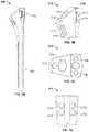
- FIG. 5Ais a perspective view of one embodiment of a stem implant according to aspects of the disclosure.
- FIG. 5Bis a perspective view of a proximal portion of the stem implant of FIG. 5A .
- FIG. 5Cis a top view of the stem implant of FIG. 5A .
- FIG. 5Dis a side view of a proximal portion of the stem implant of FIG. 5A .
- FIG. 6Ais a perspective view of the stem implant of FIG. 5A attached to the height measuring gauge of FIG. 3 in a locked configuration with the pointer and slider in a second position.
- FIG. 6Bis a perspective view of the stem implant of FIG. 5A attached to the height measuring gauge of FIG. 3 in a locked configuration with the pointer and slider in a first position.
- FIG. 7Ais a perspective view of one embodiment of a version block according to an aspect of the disclosure.
- FIG. 7Bis a cross-sectional view of the version block of FIG. 7A .
- FIG. 7Cis an isolated perspective view of a catch member of the version block of FIG. 7A .
- FIG. 7Dis an isolated perspective view of a lever of the version block of FIG. 7A .
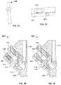
- FIG. 7Eis a cross-sectional view of the version block of FIG. 7A attached to the stem implant of FIG. 5A in an unlocked configuration.
- FIG. 7Fis a cross-sectional view of the version block of FIG. 7A attached to the stem implant of FIG. 5A in a locked configuration.
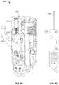
- FIG. 8Ais a side view of a height measurement gauge according to another aspect of the disclosure.
- FIG. 8Bis a cross-sectional view of the height measurement gauge of FIG. 8A .
- FIG. 9Ais a perspective view of a height measuring gauge according to another aspect of the disclosure in partial transparency in an unlocked configuration.
- FIG. 9Bis a perspective view of the height measurement gauge of FIG. 9A in partial transparency in a locked configuration.
- FIG. 9Cis a side view of a deformable plate and locking status indicator of the height measurement gauge of FIG. 9A .
- FIG. 10Ais a perspective vies of a version block according to another aspect of the disclosure.
- FIG. 10Bis a cross-section of the version block of FIG. 10A in a locked condition, with a corresponding implant omitted from the view.
- FIG. 10Cis a cross-section of the version block of FIG. 10A coupled to the stem implant of FIG. 5A in an unlocked condition.
- FIG. 10Dis a cross-section of the version block of FIG. 10A coupled to the stem implant of FIG. 5A in an intermediate condition.
- FIG. 10Eis a cross section of the version block of FIG. 10A coupled to the stem implant of FIG. 5A in a locked condition.
- FIG. 10Fis an enlarged cross section of the version block shown in FIG. 10E .
- proximalmeans closer to the heart and the term “distal” means more distant from the heart.
- distalmeans more distant from the heart.
- inferiormeans toward the feet and the term “superior” means toward the head.
- anteriormeans toward the front part or the face and the term “posterior” means toward the back of the body.
- medialmeans toward the midline of the body and the term “lateral” means away from the midline of the body.
- FIG. 1An exemplary damaged proximal humerus 10 is illustrated in FIG. 1 .
- this particular humerus 10is broken such that a first segment 20 , a second segment 30 , and a third segment 40 including a substantial portion of the humeral head are each detached from the proximal end 12 of the humerus.
- the proximal end of the humeral medullary canalmay be shaped in order to accept an implant according to known methods.
- a hand reamerfor example, may be used at a proximal humeral bearing surface 14 to remove bone material until an appropriately-shaped opening is formed in the proximal end 12 of humerus 10 for receiving an implant.
- successive reamers of increasing sizeare used in order to form an opening of the desired size.
- bearing surface 14may not be as flat as shown. Most surfaces at a fracture site are irregularly shaped unless there is a clean break between adjacent fragments. Such a surface may be resected into a generally flat shape to receive a corresponding bearing surface of a trial and/or implant stem as shown in FIG. 1 .
- trialingincludes inserting a trial stem 100 , as illustrated in FIG. 2 , into the opening in the proximal end 12 of humerus 10 .
- Trial stem 100may include a proximal portion 110 connected to a distal portion 120 , for example by welding, with an expansion bolt 130 positioned within the trial stem.
- proximal portion 110is adapted for insertion into the proximal end 12 of a prepared humerus 10 .
- Proximal portion 110may include a catch aperture 112 , a trial recess 114 , two locking pin apertures (not visible in FIG. 2 ), and a driver recess 118 .
- Catch aperture 112 and the locking pin aperturesmay be configured to mate with corresponding features on a height measuring gauge 200 , for example, as described in greater detail below with respect to FIG. 3A .
- Trial recess 114may be shaped to receive a corresponding portion of a trial humeral head (not shown) or a reverse cup humeral trial, such as that described in U.S. Pat. No. 8,545,511, the entire contents of which are hereby incorporated by reference herein.
- Trial recess 114may have a longitudinal axis that is angled with respect to a longitudinal axis of distal portion 120 so as to substantially replicate the typical geometry of a shaft and neck of the native bone prior to a fracture situation as shown in FIG. 1 .
- the distal portion 120 of trial stem 100may be structured to fit within a prepared bone canal, preferably the medullary canal of the humerus 10 .
- Distal portion 120projects along a longitudinal axis thereof from proximal portion 110 generally in the proximal-to-distal direction.
- Distal portion 120may include a first arm 122 and a second arm 124 configured to move away from each other in cooperation with expansion bolt 130 , such as that described in U.S. Pat. No. 8,216,320, the entire contents of which are hereby incorporated by reference herein.
- Distal portion 120 , or a portion thereof,may define a cavity or be configured to accept expansion bolt 130 , the cavity including a mating surface such as threads.
- Expansion bolt 130may generally include a shaft 132 with a pointed distal tip 134 .
- a proximal end of expansion bolt 130may include a head 136 , which may include a recess, such as a hex recess, to cooperate with a correspondingly shaped driving tool (not shown).
- a proximal end of shaft 132may include a mating surface, such as threads 138 , configured to mate with a corresponding surface in the cavity of distal portion 120 .
- proximal portion 110 , distal portion 120 , and expansion bolt 130may each be separate pieces prior to assembly
- trial stem 100is preferably provided to the end user as a single piece with the proximal and distal portions permanently connected, for example by welding, with the expansion bolt contained therein.
- trial stem 100which may be one chosen from a set of differently sized trial stems, is inserted into the opening in the proximal end 12 of humerus 10 , the trial stem may be temporarily secured into place by expanding the distal portion 120 .
- a usermay insert a driving tool (not shown) through driver recess 118 in the proximal portion 110 of the trial stem until the driving tool mates with the corresponding surface of the head 136 of expansion bolt 130 .
- Rotating the driving toolmay engage the threads 138 of expansion bolt 130 with corresponding threading in distal portion 120 , driving the expansion bolt distally and causing first arm 122 to be separated from second arm 124 , thus causing expansion of the distal end of distal portion 120 .
- This expansionmay result in a tighter fit of trial stem 100 in humerus 10 .
- Geometrical stopsmay be included in one or both of expansion bolt 130 and distal portion 120 to limit the distance which the expansion bolt my travel in the proximal-to-distal direction.
- the size of head 136 or a portion of the proximal shaft of expansion bolt 130may be larger than certain portions of the cavity in the distal portion 120 of trial stem 100 , such that advancement of the expansion bolt is limited to a particular range of movement.
- a height of trial stem 100 with respect to the medullary canal of the humerus 10 in which the trial stem is positionedmay be noted by a user by, for example, observing indicia printed or otherwise marked on the trial stem with respect to bearing surface 14 , for example. This height would be noted to ensure proper placement of a corresponding humeral stem implant.
- a height measuring gauge 200as illustrated in FIGS.
- Height measuring gauge 200may include a handle portion 210 which may have a flexure spring assembly similar to the broach handle described in U.S. Pat. No. 8,449,548 (“the '548 Patent”), the entire contents of which are hereby incorporated by reference.
- Handle portion 210may generally include a handle body 212 , a deformable plate 214 positioned at least partially within handle body 212 , and a loading member 216 configured to interact with the deformable plate.
- a distal end of deformable plate 214may include a catch element 218 extending therefrom, and a distal end of handle body 212 may include a pair of locking pins 220 extending therefrom.
- a cam on the loading memberinteracts with deformable plate 214 , generally pushing the plate proximally.
- handle portion 210is not attached to any device, such actuation will not deform deformable plate 214 .
- actuating loading member 216causes the deformable plate 214 to deform, locking the trial stem to the handle portion 210 of height measuring gauge 200 . This mechanism is described in greater detail in the '548 Patent.
- a stabilizing mechanismsuch as a pin 222 extending from a proximal portion of deformable plate 214 and fixed within a corresponding cavity defined by handle body 212 , for example by welding, may be provided to apply a downward force on deformable plate 214 .
- Pin 222may be fixed to body 212 while deformable plate 214 is under some amount of compression. This configuration of pin 222 and deformable plate 214 may, for example, stabilize deformable plate 214 so that it does not move or “rattle” around within body 212 when loading member 216 is placing little or no force on deformable plate 214 .
- handle body 212may include a driver aperture 224 extending the length of the body and configured to align with driver recess 118 of trial stem 100 , such that when handle portion 210 is attached to the trial stem, a driving tool may be passed through the handle body, through the proximal portion 110 of the trial stem, and into the head 136 of expansion bolt 130 to allow driving of the expansion bolt.
- Height measuring gauge 200may also include a height measurement system 230 .
- Height measurement system 230may generally include a slider 240 and a height reference member in the form of pointer 250 .
- Slider 240illustrated alone in FIG. 3C , may generally include a main body 242 , flanges 244 , one or more ball plungers 246 , and a bone position indicator 248 extending distally from the main body.
- the bone position indicator 248may take the general form of an elongated slender cylindrical rod and may be integral or monolithic with slider 240 .
- Main body 242may include a relatively large portion configured to fit within a track defined by handle body 212 , and a relatively small portion configured to extend through the track to the outside of the handle body.
- This configurationis illustrated as generally rectangular members fitting within rectangular grooves, but may take other forms, such as a dovetail configuration.
- This configurationprovides main body 242 the ability to slide proximally or distally down the track in handle body 212 while being securely maintained therein.
- At least one flange 244may extend from main body 242 and be configured to wrap around an outer portion of handle body 212 .
- Flanges 244may include texturing, such as ridges, to provide a gripping surface for a user.
- One or more ball plungers 246may be imbedded in main body 242 . In the illustrated configuration, a first pair of ball plungers 246 is positioned on a proximal end of main body 242 (only one visible in FIG.
- each ball plunger 246may be spherical and biased away from main body 242 by a spring or spring-like member, although such biasing is not required.
- the ball plungers 246may contact a wall of the track in handle body 242 , providing frictional engagement therewith.
- a usermay grip one or more flanges 244 to slide the slider 240 proximally or distally along the track, with ball plungers 246 facilitating such sliding motion while also providing friction to keep main body 242 generally in place when a sliding force is not being provided by a user.
- sliding main body 242also slides bone position indicator 248 , which may be used to determine a position of the humerus 10 , and in particular the bearing surface 14 of the proximal portion 12 of the humerus.
- the pointer 250 of height measurement system 230may generally include a main body 252 , flanges 254 , and one or more knobs 256 .
- Main body 252may be of a similar shape to the main body 242 of slider 240 , with a relatively large portion configured to fit within a track defined by handle body 212 , and a relatively small portion configured to extend through the track to the outside of the handle body.
- Main body 252may also include an aperture 253 extending the length of the main body in a proximal-to-distal direction, the aperture being sized and configured to accept the bone position indicator 248 of slider 240 therethrough.
- At least one flange 254may extend from main body 252 and be configured to wrap around an outer portion of handle body 212 .
- Each flange 254may include a knob 256 .
- Knobs 256may include threaded screws such that rotating the knobs in one direction drives the screws toward the center of pointer 250 .
- pointer 250is connected to handle portion 210 such that main body 252 is positioned inside the track defined by handle body 212 and flanges 254 are on the outside of the handle portion, rotating the knobs 256 may cause the threaded screws to drive into frictional engagement with the handle body, causing the pointer to lock in its current position.
- FIG. 3Eillustrates a cross sectional view of pointer 250 taken along the line 3 E- 3 E of FIG. 3D .
- a portion of main body 252 adjacent aperture 253may define a cavity 257 .
- Cavity 257may include a magnet 258 and a cap 259 , the cap acting to keep the magnet within the cavity.
- Magnet 258is configured to cause engagement between a distal facing surface of the main body 242 of slider 240 and a proximal facing surface of pointer 250 , such that during sliding motion of the slider, the pointer will slide along with the slider as long as the pointer is in an unlocked configuration.
- the coupled movement of the slider 240 with respect to the pointer 250may be referred to as a first mode of operation.
- knobs 256When slider 240 is at a desired location, as will be explained in greater detail below, pointer 250 will be at a corresponding desired location. At this point, the one or more knobs 256 may be rotated or tightened to keep pointer 250 in the desired location, with slider 240 removed.
- the frictional force of knobs 256 with handle body 212is preferably greater than the attractive force between magnet 258 and the distal portion of the main body 242 of slider 240 , such that removing the slider 242 does not cause pointer 250 to change positions once the pointer is in the locked configuration.
- the decoupled movement of the slider 240 with respect to the pointer 250may be referred to as a second mode of operation.
- height measurement gauge 200may be connected to trial stem 100 prior to insertion into the medullary canal, and then used to insert the trial stem into the medullary canal and to objectively mark the height of the trial stem.
- height measuring gauge 200is locked onto trial stem 100 , as described above and illustrated in FIG. 4A , the trial stem is inserted into the previously formed opening to the medullary canal in the proximal portion 12 of humerus 10 . If the user determines that a different sized trial stem 100 is desirable at this point, the user may remove the height measuring gauge 200 and trial stem 100 , disconnect the original trial stem, and attach a differently sized trial stem to the height measuring gauge.
- handle 210may include a plurality of indicia, such as gradations 211 (only illustrated in FIG. 4A ) that may referenced in concert with a contralateral X-ray template of the healthy bone.
- the contralateral X-ray templatemay include corresponding markings as handle 210 to facilitate the choice of an appropriately sized stem 100 .
- a driving toolmay be inserted through the driver aperture 224 in handle portion 210 , through driver recess 118 of the proximal portion 110 of trial stem 100 , and finally mate the driving tool with the head 136 of expansion bolt 130 .
- the driving toolmay be rotated, torqued, or otherwise used to drive expansion bolt 130 , causing expansion of the first and second arms 122 , 124 of the distal portion 120 of trial stem 100 , causing the trial stem to have a snug fit within the proximal portion 12 of humerus 10 .
- the usermay grip slider 240 and slide it distally until a distal end surface 249 of bone position indicator 248 makes contact with a bearing surface 14 of the humerus, the position of slider 240 and pointer 250 being shown in FIG. 4B .
- knobs 256may be tightened to frictionally engage handle body 212 .
- Pointer 250may now serve as an objective reference to a height of trial stem 100 with respect to humerus 10 for later reference. Because pointer 250 is frictionally locked, slider 240 may be slid proximally while the pointer remains in place, the magnetic interaction between magnet 258 and the main body 242 of the slider not affecting the position of the pointer, as illustrated in FIG. 4C .
- handle portion 210may be shifted to the unlocked configuration by actuating loading member 216 as described above. This allows a user to remove height measuring gauge 200 , as shown in FIG. 4D , while leaving trial stem 100 expanded in place.
- trial stem 100With trial stem 100 secure in place, any one of a number of additional trial components may be attached to trial stem 100 via trial recess 114 , such as a trial humeral head or a reverse cup humeral trial (not shown).
- trial recess 114may provide compatibility with a greater number of other trial components compared to known expandable trial stems that have a protruding peg or similar protruding structure onto which other trial components fit.
- the position of trial recess 114is possible at least partly due to the location of expandable bolt 130 .
- an expansion bolt extended close to the proximal end of the known trial stemmaking such a trial recess incompatible as any component inserted into a recess made in the known trial would make contact with a proximal end of the expansion bolt.
- the relatively distal position of expansion bolt 130 and its total encapsulation within trial stem 100facilitates the ability of using trial recess 114 which, as noted above, may accept a number of different types of trial components.
- any trial components still connected to trial stem 100may be removed.
- Trial stem 100may then be removed, with or without the use of height measuring gauge 200 .
- a particular sized stem implant 300is chosen.
- An exemplary embodiment of stem implant 300is illustrated in FIG. 5A and may be structurally similar to trial stem 100 in certain respects.
- Stem implant 300may be monolithic with a proximal portion 310 and a distal portion 320 .
- Proximal portion 310 of stem implant 300shown in greater detail in FIGS. 5B-D , may include a catch aperture 312 , an implant recess 314 , and two locking pin apertures 316 .
- Implant recess 314may be configured to accept a humeral head implant, reverse cup humeral implant, or other compatible implant.
- Proximal portion 310may also include a number of features to facilitate securing portions of humerus 10 , such as first segment 20 and second segment 30 , to stem implant 300 .
- a first pair of suture holes 317 amay be formed on a lateral-anterior side of proximal portion 310 and a second pair of suture holes 317 b may be formed on a lateral-posterior side of the proximal portion.
- a third pair of suture holes 317 cmay be formed on a medial side of proximal portion 310 .
- the suture holes 317 a - cmay facilitate securing one or more bone fragments to stem implant 300 via sutures (not illustrated).
- One suture pocket 319 amay be formed on the lateral-anterior side of proximal portion 310 , and may be connected to suture holes 317 a .
- Another suture pocket(not visible in FIGS. 5A-D ) may be formed on the lateral-posterior side of proximal portion 310 , and may be connected to suture holes 317 b .
- the suture pocketsmay, for example, facilitate the insertion of a suture needle.
- the usermay connect the stem implant to height measuring gauge 200 and lock the stem implant using loading member 216 , as described above.
- a usermay insert stem implant 300 into the prepared hole in humerus 10 using height measuring gauge 200 .
- pointer 250is still locked into the position determined during insertion of trial stem 100 , described above in relation to FIGS. 4A-C .
- the usermay slide slider 240 distally until it contacts pointer 250 , as illustrated in FIG. 6A .
- the usermay confirm that the distal end of bone position indicator 248 is in contact with bearing surface 14 of the proximal portion 12 of humerus 10 . This confirms that the height of stem implant 300 with respect to humerus 10 corresponds to the desired height determined using trial stem 100 , reducing or eliminating the requirement for the user to subjectively assess the respective heights.
- the usermay assess and confirm a correct rotational position of stem implant 300 at this point using one or more of threaded apertures 260 , 270 , and 280 , as shown in FIG. 4B .
- Each threaded aperture 260 , 270 , and 280is a threaded aperture at varying angles.
- one of the threaded aperturesmay be angled at approximately 20 degrees, another may be angled at approximately 30 degrees, and the third may be angled at approximately 40 degrees.
- a version rod taking the form of a straight rod with a threaded endmay be threaded into any one of the threaded apertures 260 , 270 , or 280 .
- the version rodmay be used to provide a line of reference for comparison, for example, with the position of the forearm relative to the shoulder.
- the anglewill be known or estimated based on which threaded aperture 260 , 270 , or 280 the version rod extends from. More or fewer than three threaded apertures may be provided, and the particular angles are not limited to 20, 30, and 40 degrees. Further, threaded apertures may be provided on one or both sides of handle 210 . This procedure is essentially the same whether measurements are being taken in relation to trial stem 100 or stem implant 300 .
- the usermay then unscrew the knobs 256 of pointer 250 , causing the pointer to transition into an unlocked configuration. Then, slider 240 may be slid proximally, causing pointer 250 to slide proximally due to the magnetic connection between the pointer and slider, as illustrated in FIG. 6B . Finally, the user may rotate loading member 246 to unlock handle portion 210 of height measuring gauge 200 from stem implant 300 . At this point, the user may attach a humeral head or other implant component to stem implant 300 , and complete the particular implant procedure desired.
- a version block 400may be used in conjunction with a version rod (not illustrated) to determine the rotational position of stem implant 300 or trial stem 100 if a user does not wish to use threaded apertures 260 , 270 , and 280 of handle 210 .
- version block 400is a monolithic structure with a number of components that facilitate locking of the version block to stem implant 300 .
- version block 400may include a pair of locking pins 420 configured to mate with locking pin apertures 316 of stem implant 300 .
- Version block 400may also include a catch member 418 configured to mate with catch aperture 312 of stem implant 300 .
- version block 400may also include a driver recess 419 configured to allow passage of a driving tool through the version block and into trial stem 100 when the version block is attached to the trial stem.
- the locking mechanism of version blockmay generally include catch member 418 , spring cap 450 , spring 460 , lever 470 , and actuator 480 .
- Catch member 418which is also illustrated in FIG. 7C , may be a generally cylindrical member with a flange that cooperates with spring 460 , the spring contacting the flange of the catch member on a first end and spring cap 450 on a second end opposite the first end. This configuration provides for a force that biases catch member 418 beyond a distal end of version block 400 .
- a distal end of the flange of catch member 418may be configured to contact a proximal face of lever 470 , with a cylindrical portion of the catch member extending through a slot 472 in the lever.
- Lever 470which is also illustrated in FIG. 7D , is configured to pivot about pin 490 , the pin connecting the lever to version block 400 through a pin aperture 474 in the lever.
- the flange of catch member 418does not fit through slot 472 in lever 470 , so the biasing force provided by spring 460 on the catch member is transmitted to the lever, causing the lever to be biased in a counterclockwise direction in the view of FIG. 7B .
- One end of lever 470is configured to contact a distal end of actuator 480 .
- Actuator 480may generally comprise a cylindrical pin with an enlarged head 482 and a slot 484 .
- Actuator 480is connected to version block 400 by another pin 490 extending through slot 484 of the actuator.
- Actuator 480may slide into or out of version block 400 , the sliding motion being limited by enlarged head 482 and the cooperation of pin 490 with slot 484 .
- actuator 480is biased in a proximal direction resulting from the transmission of force from spring 460 to catch member 418 to lever 470 and finally to the actuator.
- a usermay press distally on the enlarged head 482 of actuator 480 to cause catch member 418 to retract within the body of version block 400 .
- a usermay stop the application of force on the enlarged head 482 of actuator 480 to cause the spring 460 to push catch member 418 partially out of version block 400 .
- a userdepresses actuator 480 to retract catch member 418 inside the version block.
- Locking pins 420are inserted into corresponding locking pin apertures 316 of stem implant 300 , as illustrated in FIG. 7E .
- the userthen aligns catch member 418 with catch aperture 312 and releases actuator 480 , causing the bias force provided by spring 460 to push the catch member distally out of version block 400 and into corresponding catch aperture 312 of stem implant 300 , as illustrated in FIG. 7F .
- a version rod(not illustrated) may be inserted into any one of a number of version rod apertures 495 in version block 400 , as illustrated in FIG. 7A .
- the version rodmay be generally “L” shaped or straight, as noted above, with one end of the rod extending to provide a line of reference for comparison, for example, with the position of the forearm relative to the shoulder.
- version block 400may be used with trial stem 100 or stem implant 300 to assess the rotational position of the trial stem or stem implant in relation to the anatomy during trialing or assessment of implant position. Because version rods are generally known in the art, they are not described in greater detail herein.
- height measurement gauge 200 ′is illustrated in FIGS. 8A-8B .
- Height measurement gauge 200 ′is similar to height measurement gauge 200 in nearly all respects, with the exception of the following.
- the height measurement systemonly includes a sliding member 240 ′, without a pointer as provided with height measurement gauge 200 .
- Sliding member 240 ′may include a marking, such as an arrow or a notch, to reference corresponding indicia 211 ′ on the handle body 210 ′ of height measurement gauge 200 ′.
- slider 240 ′is slid distally until a distal end surface 249 ′ of bone position indicator 248 ′ makes contact with a bearing surface 14 of the humerus, much in the same way as described in connection with height measurement gauge 200 .
- the usermay take note of the position of the arrow or other indicator on sliding member 240 ′ with respect to indicia 211 ′ on the body of handle 210 ′. This provides an objective indication of the position of bone position indicator 248 ′ when trial stem 100 is properly inserted into the bone.
- sliding member 240 ′When inserting stem implant 300 using height measurement gauge 200 ′, sliding member 240 ′ may be positioned so that the arrow or other indicator aligns with the corresponding indicia 211 ′ as determined while using trial stem 100 .
- sliding member 240 ′may include teeth, screws, or other members to lock the sliding member 240 ′ in a particular position with respect to the body of handle 210 ′.
- a structure similar to knobs 256 of pointer 250may be used with sliding member 240 ′ to achieve such locking.
- height measuring gauge 200 ′′is nearly identical to height measuring gauge 200 , with the exception that height measuring gauge 200 ′′ includes a locking status indicator mechanism, for example locking status pin 290 ′′.
- Pin 290 ′′extends from a proximal portion of deformable plate 214 ′′ and is positioned within a corresponding cavity defined by handle body 212 ′′.
- Pin 290 ′′may be welded or otherwise fixed to deformable plate 214 ′′ but free to slide within the corresponding cavity defined by handle body 212 ′′.
- Pin 290 ′′may help indicate to the user whether loading member 216 ′′ is in a locked or unlocked configuration. For example, when in an unlocked configuration, as shown in FIG.
- pin 290 ′′may be generally flush with a proximal end of handle body 212 ′′. After a transition to a locked configuration, as shown in FIG. 9B , pin 290 ′′ may be pushed proximally so as to extend beyond the proximal end of handle body 212 ′′, providing a user with a visual indication that loading member 216 ′′ is in a locked configuration. The length and position of pin 290 ′′ may be altered to vary the exact position of the pin that indicates the locked or unlocked configuration. Deformable plate 214 ′′ and pin 290 ′′ are illustrated without handle body 212 ′′ in FIG. 9C .
- FIG. 10Ais a perspective view of a version block 500 that combines aspects of the various handles and version blocks described above.
- Version block 500may be a monolithic structure with a number of components that facilitate locking of the version block to trial stem 100 and/or stem implant 300 .
- version block 500may include a pair of locking pins 520 (only one visible in FIG. 10A ) configured to mate with the locking pin apertures of trial stem 100 and locking pin apertures 316 of stem implant 300 .
- Version block 500may also include a catch member 518 configured to mate with catch aperture 112 of trial stem 100 and catch aperture 312 of stem implant 300 .
- the catch member 518 and locking pins 520may extend from the distal end of the version block 500 at non-parallel angles.
- Version block 500may include a driver recess 519 configured to allow passage of a driving tool through the version block and into trial stem 100 when the version block is attached to the trial stem.
- FIG. 10Billustrates a cross-section of version block 500 .
- the locking mechanism of version block 500may generally include a loading member 516 , which may be a rotatable handle, and a plate 514 which includes catch member 518 .
- Catch member 518may be a generally cylindrical member coupled to a distal end of plate 514 .
- An actuator 580may include a distal tip that may fit within a recess in the proximal end of plate 514 .
- Actuator 580may be a pin and include a proximal cap that is fixed with respect to the housing of version block 500 , with a spring 582 positioned around actuator 580 , with a proximal end of the spring abutting the proximal cap of the actuator.
- a distal end of spring 582may abut a proximal end of plate 514 .
- Plate 514may include one or more vertical slots that engage with pins 590 , so that the plate is able to move vertically with the slots sliding over the pins. With this configuration, spring 582 biases plate 514 to a distal position relative to the version block 500 in the absence of applied forces. This position may be referred to as an unlocked condition and is shown in FIG. 10C .
- Plate 514may include a hooked projection 517 that interacts with loading member 516 to assist in transitioning the version block from an unlocked condition, shown in FIG. 10C , through an intermediate condition shown in FIG. 10D , to a locked condition, shown in FIGS. 10E-F , as described in greater detail below.
- load member 518may be inserted into the catch member aperture 312 of the stem implant 300 (or the corresponding catch member of the trial stem 100 ) and locking pins 520 may be inserted into the locking pin apertures 316 of the stem implant (or the corresponding locking pin apertures of the trial stem).
- Loading member 516includes a body 570 with an aperture that a pin 590 may pass through so that the loading member is rotatable about the pin.
- Body 570may include a pair of projections 571 that are positioned on either side of a stopper pin 592 , which may be similar or identical in structure to the other pins 590 .
- the projections 571may limit the range which the loading member 516 may rotate, with the projections contacting the stopper pin 592 at the maximum ranges of rotation in either direction.
- Loading member 516may also include a flexure member 572 that has a first end coupled to loading member 516 and a second free end 573 .
- Flexure member 572may be generally “U”-shaped so that the flexure member extends in a first direction from its connection point to loading member 516 , and then turns back so that the second free end 573 is substantially parallel to the first end of the flexure member. With this configuration, the second free end 573 may move toward (or away from) the first end of flexure member 572 as compressive force is applied to (or released from) the second free end 573 .
- the second end 573 of flexure member 572may include a projection 574 , with grooves 575 , 576 on either side of the projection.
- the projection 517 of plate 514may rest within groove 575 .
- One of the projections 571 of body 570 of loading member 516may help ensure that the flexure member 572 cannot be rotated so that the projection 517 loses contact with the flexure member.
- the projection 517 of plate 514begins to ride up the second end 573 of flexure member 572 toward projection 574 , as shown in FIG. 10D .
- the flexure member 572begins to compress as the second end 573 of the flexure member moves toward the first end.
- plate 514is pulled proximally causing spring 582 to compress. The user may continue to rotate loading member 516 until projection 517 passes over projection 574 and comes to rest in groove 576 and the version block 500 is in the locked condition shown in FIG. 10E .
- the flexure member 572springs back to relieve some of the compressive forces previously applied on the flexure member.
- the catch member 518is pulled proximally in catch aperture 312 of stem implant 300 (or the corresponding catch aperture in trial stem 100 ). Similar to the other embodiments described herein, the force applied to catch member 518 combined with the positioning of locking pins 520 within corresponding locking pin apertures 316 of stem implant 300 or corresponding locking pin apertures of trial stem 100 , results in the version block 500 being locked to the stem implant or trial stem. Once the version block 500 is in the locked condition of FIGS. 10E-F , the user may release the loading member 516 .
- the projection 574 of flexure member 572maintains the projection 517 of plate 514 in groove 576 in the absence of applied force. Further, the flexure member 572 , in the locked condition of the version block 500 , applies an upward force on plate 514 so that version block 500 maintains a compressive force on the stem implant 300 or trial stem 100 .
- the second projection 571 of the main body 570may interact with stopper pin 592 to limit further rotation of the loading member 516 in the clockwise direction.
- the trial stem 100When version block 500 is in the locked condition, the trial stem 100 may be inserted into the proximal humerus 12 and then expanded by passing a driver tool through the driver recess 519 and expanding the trial as described in connection with other embodiments above.
- the height of the trial stem 100may be determined, for example by using indicia or other markings on the trial stem that correspond to height indicia or markings on stem implant 300 .
- Versionmay be confirmed by using a version rod with one or more version rod apertures 595 , in substantially the same manner as described in connection to version block 400 . If the trialing is successful, the user may de-expand the trial stem 100 and remove trial stem 100 from the humerus 12 by pulling the version block 500 proximally.
- the version block 500may be transitioned to the unlocked condition and decoupled from the trial stem 100 . While in the unlocked condition, version block 500 coupled to stem implant 300 , and transitioned back to the locked condition. The stem implant 300 may then be inserted into the proximal humerus 12 until the height markings or indicia on the stem implant are at the height previously recorded from the trial stem 100 . Version may again be confirmed using a version rod (not shown) with version rod apertures 595 , in substantially the same manner as described in connection with other embodiments above. If the implant position is satisfactory, the user may transition the version block 500 to the unlocked condition and remove the version block from the stem implant 300 , leaving the stem implant in place. Additional components, such as a prosthetic humeral head, may be coupled to the stem implant 300 and the procedure completed.
- a prosthetic humeral headmay be coupled to the stem implant 300 and the procedure completed.
Landscapes
- Health & Medical Sciences (AREA)
- Orthopedic Medicine & Surgery (AREA)
- Transplantation (AREA)
- Life Sciences & Earth Sciences (AREA)
- Oral & Maxillofacial Surgery (AREA)
- Public Health (AREA)
- Engineering & Computer Science (AREA)
- Biomedical Technology (AREA)
- Heart & Thoracic Surgery (AREA)
- Vascular Medicine (AREA)
- Veterinary Medicine (AREA)
- Animal Behavior & Ethology (AREA)
- General Health & Medical Sciences (AREA)
- Cardiology (AREA)
- Physical Education & Sports Medicine (AREA)
- Physics & Mathematics (AREA)
- General Physics & Mathematics (AREA)
- Biophysics (AREA)
- Nuclear Medicine, Radiotherapy & Molecular Imaging (AREA)
- Surgery (AREA)
- Prostheses (AREA)
Abstract
Description
This application is a continuation-in-part of U.S. patent application Ser. No. 14/279,572, filed on May 16, 2014, the disclosure of which is hereby incorporated by reference herein
The present invention relates to guides for determining a desired position and orientation of an implant in a fracture setting, and in particular relates to guides for gauging the height and/or orienting the version of an implant with respect to at least one bone fragment.
A joint replacement procedure is sometimes necessary to repair a joint having a diseased or damaged articular surface. Such a procedure may involve removal of the diseased or damaged portions of the joint and replacing them with a prosthetic implant. This is often a desirable procedure for ball-and-socket type joints, particularly the shoulder and hip joints. A shoulder joint replacement procedure, for example, often involves removal of the humeral head and replacement thereof with an implant including a stem and a head. It is important that the implant be positioned correctly within the joint in order to ensure that appropriate joint kinematics, including range of motion, are preserved so as to replicate, as closely as possible, those of the original joint.
The structure of prosthetic joint components has been developed to be suited for permanent implantation into the joint and includes features that may promote bony ingrowth, adhesion using cement, press-fit or a combination thereof. Particularly, in the case of implants including a stem, such as those used in shoulder arthroplasty, these features are generally included on the outside surface of the stem. Such features may not be well-suited for use during the assessment of joint kinematics. Accordingly, instruments such as trials have been developed to be used in this part of the procedure. Generally, trials are affixed to the bone during joint kinematic evaluation and removed therefrom after a proper position for the implant has been determined.
Typically, trials are designed to correspond to an implant in size and shape. In a shoulder arthroplasty procedure, for example, a trial may be designed to be temporarily inserted into a prepared medullary canal of the humerus in a manner similar to that of an implant. Known trials may take many forms. For example, an expanding trial stem, such as that described in U.S. Pat. No. 8,216,320, the entire contents of which are hereby incorporated by reference herein, includes a stem that may be expanded after insertion into the medullary canal. When using such trial stems, particularly in shoulder replacements, it may be difficult to establish the proper position and orientation for the implant in the humerus. It would thus be desirable to have guides that simplify the determination of proper positioning of the implant during use of a trial stem.
According to one aspect of the disclosure, a prosthetic shoulder implant system includes a prosthetic humeral implant and a version device for measuring a rotational position of the prosthetic humeral implant. The prosthetic humeral implant includes a catch member aperture and a first locking pin aperture. The version device includes a rotatable member, a plate, and a first locking pin. The rotatable member has a body and a flexure member. The plate has a catch member adapted to mate with the catch member aperture, and a projection in contact with the flexure member, the catch member extending from a distal portion of the version device along a first axis. The first locking pin extends from the distal portion of the version device along a second axis non-parallel to the first axis and is adapted to mate with the first locking pin aperture. In an unlocked condition of the system, the rotatable member has a first rotated position in which the flexure member is in an uncompressed state and the plate is in a first position. In a locked condition of the system, the rotatable member has a second rotated position in which the flexure member is in a compressed state and the plate is in a second position proximal of the first position.
The prosthetic humeral implant may be a permanent implant stem that includes a plurality of indicia for marking the height of the permanent implant stem. The prosthetic humeral implant may be a trial stem implant that includes a plurality of indicia for marking the height of the trial stem implant. A biasing member may bias the plate to the first position. The body of the rotatable member may include a first projection in contact with a stopper pin when the rotatable member is in the first rotated position, the first projection resisting rotation of the rotatable member in a first rotational direction. The body of the rotatable member may include a second projection in contact with the stopper pin when the rotatable member is in the second rotated position, the second projection resisting rotation of the rotatable member in a second rotational direction opposite the first rotational direction.
The flexure member may include a first groove, a second groove, and a projecting portion between the first and second grooves. In the unlocked condition of the system, the projection of the plate may be positioned within the first groove. In the locked condition of the system, the projection of the plate may be positioned within the second groove. The system may include an intermediate condition in which the rotatable member is in a third rotated position between the first and second rotated positions and the projection of the plate contacts the projecting portion of the flexure member. The flexure member may be at a maximum amount of compression in the intermediate condition of the system.
When the catch member is positioned within the catch member aperture, the first locking pin is positioned within the first locking pin aperture, and the system is in the locked condition, a compressive force may be maintained between the version device and the prosthetic humeral implant. The version device may include a plurality of version rod apertures. The version rod apertures may be threaded apertures configured to mate with a version rod. Each of the plurality of version rod apertures may be angled differently than each other version rod aperture. The plate may include a first slot and the version device may include a first plate pin positioned within the first slot. The first plate pin may guide movement of the plate between the first position of the plate and the second position of the plate. The prosthetic humeral implant may be a permanent implant stem, and the system may further include a trial stem including a trial catch member aperture adapted to mate with the catch member, and a trial first locking pin aperture adapted to mate with the first locking pin aperture, the permanent implant stem including a plurality of height indicia corresponding to a plurality of height indicia of the trial stem.
In describing preferred embodiments of the disclosure, reference will be made to the directional nomenclature used in describing the human body. It is noted that this nomenclature is used only for convenience and that it is not intended to be limiting with respect to the scope of the invention. When referring to specific directions in relation to a device, the device is understood to be described only with respect to its orientation and position during an exemplary application to the human body. As used herein when referring to bones or other parts of the body, the term “proximal” means closer to the heart and the term “distal” means more distant from the heart. The term “inferior” means toward the feet and the term “superior” means toward the head. The term “anterior” means toward the front part or the face and the term “posterior” means toward the back of the body. The term “medial” means toward the midline of the body and the term “lateral” means away from the midline of the body. Further, although the devices and methods described herein are generally described in relation to human shoulder replacements, it should be understood that the devices and methods are not intended to be so limited and could be used with other joints, such as other ball and socket joints, including the hip, for example.
Generally, the replacement of a humeral head with a prosthetic implant during shoulder arthroplasty involves gaining access to the shoulder joint through a retracted incision and removing the damaged humeral head. An exemplary damagedproximal humerus 10 is illustrated inFIG. 1 . Although such breaks giving rise to a plurality of bone fragments may occur in any number of ways, thisparticular humerus 10 is broken such that afirst segment 20, asecond segment 30, and athird segment 40 including a substantial portion of the humeral head are each detached from theproximal end 12 of the humerus. After removal of thehumeral head 40, the proximal end of the humeral medullary canal may be shaped in order to accept an implant according to known methods. In one exemplary method, a hand reamer, for example, may be used at a proximalhumeral bearing surface 14 to remove bone material until an appropriately-shaped opening is formed in theproximal end 12 ofhumerus 10 for receiving an implant. Typically, successive reamers of increasing size are used in order to form an opening of the desired size. In many cases, bearingsurface 14 may not be as flat as shown. Most surfaces at a fracture site are irregularly shaped unless there is a clean break between adjacent fragments. Such a surface may be resected into a generally flat shape to receive a corresponding bearing surface of a trial and/or implant stem as shown inFIG. 1 .
Once anappropriate bearing surface 14 and opening is formed for receiving an implant, trialing is conducted to determine the proper size and location for the implant prior to implantation thereof. According to one example of the present disclosure, trialing includes inserting atrial stem 100, as illustrated inFIG. 2 , into the opening in theproximal end 12 ofhumerus 10.Trial stem 100 may include aproximal portion 110 connected to adistal portion 120, for example by welding, with anexpansion bolt 130 positioned within the trial stem. Generally,proximal portion 110 is adapted for insertion into theproximal end 12 of aprepared humerus 10.Proximal portion 110 may include acatch aperture 112, atrial recess 114, two locking pin apertures (not visible inFIG. 2 ), and adriver recess 118.Catch aperture 112 and the locking pin apertures may be configured to mate with corresponding features on aheight measuring gauge 200, for example, as described in greater detail below with respect toFIG. 3A .Trial recess 114 may be shaped to receive a corresponding portion of a trial humeral head (not shown) or a reverse cup humeral trial, such as that described in U.S. Pat. No. 8,545,511, the entire contents of which are hereby incorporated by reference herein.Trial recess 114 may have a longitudinal axis that is angled with respect to a longitudinal axis ofdistal portion 120 so as to substantially replicate the typical geometry of a shaft and neck of the native bone prior to a fracture situation as shown inFIG. 1 .
Thedistal portion 120 of trial stem100 may be structured to fit within a prepared bone canal, preferably the medullary canal of thehumerus 10.Distal portion 120 projects along a longitudinal axis thereof fromproximal portion 110 generally in the proximal-to-distal direction.Distal portion 120 may include afirst arm 122 and asecond arm 124 configured to move away from each other in cooperation withexpansion bolt 130, such as that described in U.S. Pat. No. 8,216,320, the entire contents of which are hereby incorporated by reference herein.Distal portion 120, or a portion thereof, may define a cavity or be configured to acceptexpansion bolt 130, the cavity including a mating surface such as threads.
Aftertrial stem 100, which may be one chosen from a set of differently sized trial stems, is inserted into the opening in theproximal end 12 ofhumerus 10, the trial stem may be temporarily secured into place by expanding thedistal portion 120. To expand thedistal portion 120, a user may insert a driving tool (not shown) throughdriver recess 118 in theproximal portion 110 of the trial stem until the driving tool mates with the corresponding surface of thehead 136 ofexpansion bolt 130. Rotating the driving tool may engage thethreads 138 ofexpansion bolt 130 with corresponding threading indistal portion 120, driving the expansion bolt distally and causingfirst arm 122 to be separated fromsecond arm 124, thus causing expansion of the distal end ofdistal portion 120. This expansion may result in a tighter fit of trial stem100 inhumerus 10. Geometrical stops may be included in one or both ofexpansion bolt 130 anddistal portion 120 to limit the distance which the expansion bolt my travel in the proximal-to-distal direction. For example, the size ofhead 136 or a portion of the proximal shaft ofexpansion bolt 130 may be larger than certain portions of the cavity in thedistal portion 120 oftrial stem 100, such that advancement of the expansion bolt is limited to a particular range of movement.
According to known methods, a height of trial stem100 with respect to the medullary canal of thehumerus 10 in which the trial stem is positioned may be noted by a user by, for example, observing indicia printed or otherwise marked on the trial stem with respect to bearingsurface 14, for example. This height would be noted to ensure proper placement of a corresponding humeral stem implant. However, in another embodiment according to the present disclosure, aheight measuring gauge 200, as illustrated inFIGS. 3A-B , may be connected totrial stem 100 prior to insertion into the medullary canal, and then used to insert trial stem into the medullary canal and to objectively mark the height of the trial stem with respect to a location or surface of the intact humerus, such as bearingsurface 14, for example.Height measuring gauge 200 may include ahandle portion 210 which may have a flexure spring assembly similar to the broach handle described in U.S. Pat. No. 8,449,548 (“the '548 Patent”), the entire contents of which are hereby incorporated by reference.Handle portion 210 may generally include ahandle body 212, adeformable plate 214 positioned at least partially withinhandle body 212, and aloading member 216 configured to interact with the deformable plate. A distal end ofdeformable plate 214 may include acatch element 218 extending therefrom, and a distal end ofhandle body 212 may include a pair of lockingpins 220 extending therefrom. Briefly, as a user actuatesloading member 216 by rotating the loading member clockwise (transition illustrated fromFIG. 3A toFIG. 3B ), a cam on the loading member interacts withdeformable plate 214, generally pushing the plate proximally. Ifhandle portion 210 is not attached to any device, such actuation will not deformdeformable plate 214. However, whencatch element 218 is positioned insidecatch aperture 112 oftrial stem 100 and lockingpins 220 are positioned inside the locking pin apertures of the trial stem, actuatingloading member 216 causes thedeformable plate 214 to deform, locking the trial stem to thehandle portion 210 ofheight measuring gauge 200. This mechanism is described in greater detail in the '548 Patent.
It should be noted that a stabilizing mechanism, such as apin 222 extending from a proximal portion ofdeformable plate 214 and fixed within a corresponding cavity defined byhandle body 212, for example by welding, may be provided to apply a downward force ondeformable plate 214.Pin 222 may be fixed tobody 212 whiledeformable plate 214 is under some amount of compression. This configuration ofpin 222 anddeformable plate 214 may, for example, stabilizedeformable plate 214 so that it does not move or “rattle” around withinbody 212 when loadingmember 216 is placing little or no force ondeformable plate 214. It should further be noted thathandle body 212 may include adriver aperture 224 extending the length of the body and configured to align withdriver recess 118 oftrial stem 100, such that whenhandle portion 210 is attached to the trial stem, a driving tool may be passed through the handle body, through theproximal portion 110 of the trial stem, and into thehead 136 ofexpansion bolt 130 to allow driving of the expansion bolt.
Thepointer 250 ofheight measurement system 230, illustrated alone inFIG. 3D , may generally include amain body 252,flanges 254, and one or more knobs256.Main body 252 may be of a similar shape to themain body 242 ofslider 240, with a relatively large portion configured to fit within a track defined byhandle body 212, and a relatively small portion configured to extend through the track to the outside of the handle body.Main body 252 may also include anaperture 253 extending the length of the main body in a proximal-to-distal direction, the aperture being sized and configured to accept thebone position indicator 248 ofslider 240 therethrough. At least oneflange 254, and preferably two, may extend frommain body 252 and be configured to wrap around an outer portion ofhandle body 212. Eachflange 254 may include aknob 256.Knobs 256 may include threaded screws such that rotating the knobs in one direction drives the screws toward the center ofpointer 250. Whenpointer 250 is connected to handleportion 210 such thatmain body 252 is positioned inside the track defined byhandle body 212 andflanges 254 are on the outside of the handle portion, rotating theknobs 256 may cause the threaded screws to drive into frictional engagement with the handle body, causing the pointer to lock in its current position.
As noted above, in an embodiment according to the present disclosure,height measurement gauge 200 may be connected totrial stem 100 prior to insertion into the medullary canal, and then used to insert the trial stem into the medullary canal and to objectively mark the height of the trial stem. Onceheight measuring gauge 200 is locked ontotrial stem 100, as described above and illustrated inFIG. 4A , the trial stem is inserted into the previously formed opening to the medullary canal in theproximal portion 12 ofhumerus 10. If the user determines that a differentsized trial stem 100 is desirable at this point, the user may remove theheight measuring gauge 200 andtrial stem 100, disconnect the original trial stem, and attach a differently sized trial stem to the height measuring gauge. If thetrial stem 100 is an appropriate size, the user may continue. At this point,slider 240 andpointer 250 are in a first or initial proximal position, with the pointer attached to the slider viamagnet 258 as described above.Pointer 250 is also in an unlocked configuration. To facilitate the initial choice of an appropriatelysized trial stem 100, handle210 may include a plurality of indicia, such as gradations211 (only illustrated inFIG. 4A ) that may referenced in concert with a contralateral X-ray template of the healthy bone. The contralateral X-ray template may include corresponding markings ashandle 210 to facilitate the choice of an appropriatelysized stem 100.
Once trial stem100 is inserted intohumerus 10 to a desirable depth as determined by the user, a driving tool may be inserted through thedriver aperture 224 inhandle portion 210, throughdriver recess 118 of theproximal portion 110 oftrial stem 100, and finally mate the driving tool with thehead 136 ofexpansion bolt 130. The driving tool may be rotated, torqued, or otherwise used to driveexpansion bolt 130, causing expansion of the first andsecond arms distal portion 120 oftrial stem 100, causing the trial stem to have a snug fit within theproximal portion 12 ofhumerus 10.
Before or after causing such expansion, the user may gripslider 240 and slide it distally until adistal end surface 249 ofbone position indicator 248 makes contact with a bearingsurface 14 of the humerus, the position ofslider 240 andpointer 250 being shown inFIG. 4B . At this stage, knobs256 may be tightened to frictionally engagehandle body 212.Pointer 250 may now serve as an objective reference to a height of trial stem100 with respect tohumerus 10 for later reference. Becausepointer 250 is frictionally locked,slider 240 may be slid proximally while the pointer remains in place, the magnetic interaction betweenmagnet 258 and themain body 242 of the slider not affecting the position of the pointer, as illustrated inFIG. 4C . Oncepointer 250 is locked into the desired position andslider 240 is back at an original proximal position, handleportion 210 may be shifted to the unlocked configuration by actuatingloading member 216 as described above. This allows a user to removeheight measuring gauge 200, as shown inFIG. 4D , while leavingtrial stem 100 expanded in place.
With trial stem100 secure in place, any one of a number of additional trial components may be attached totrial stem 100 viatrial recess 114, such as a trial humeral head or a reverse cup humeral trial (not shown). One benefit of thetrial stem 100 illustrated herein is that thetrial recess 114 may provide compatibility with a greater number of other trial components compared to known expandable trial stems that have a protruding peg or similar protruding structure onto which other trial components fit. The position oftrial recess 114 is possible at least partly due to the location ofexpandable bolt 130. In certain known expandable trial stems, an expansion bolt extended close to the proximal end of the known trial stem, making such a trial recess incompatible as any component inserted into a recess made in the known trial would make contact with a proximal end of the expansion bolt. However, the relatively distal position ofexpansion bolt 130 and its total encapsulation withintrial stem 100, as disclosed herein, facilitates the ability of usingtrial recess 114 which, as noted above, may accept a number of different types of trial components. Once the desired trial component is connected totrial stem 100, the user may conduct trialing to confirm the size and placement of trial stem100 as well as any other trial components being used.
After the user is satisfied with the results of trialing, any trial components still connected totrial stem 100 may be removed.Trial stem 100 may then be removed, with or without the use ofheight measuring gauge 200. Based on the results of trialing, a particularsized stem implant 300 is chosen. An exemplary embodiment ofstem implant 300 is illustrated inFIG. 5A and may be structurally similar totrial stem 100 in certain respects.Stem implant 300 may be monolithic with aproximal portion 310 and adistal portion 320.Proximal portion 310 ofstem implant 300, shown in greater detail inFIGS. 5B-D , may include acatch aperture 312, animplant recess 314, and twolocking pin apertures 316. Theapertures trial stem 100, facilitate the connection betweenhandle portion 210 ofheight measuring gauge 200 withstem implant 300.Implant recess 314 may be configured to accept a humeral head implant, reverse cup humeral implant, or other compatible implant.Proximal portion 310 may also include a number of features to facilitate securing portions ofhumerus 10, such asfirst segment 20 andsecond segment 30, to stemimplant 300. For example, a first pair ofsuture holes 317amay be formed on a lateral-anterior side ofproximal portion 310 and a second pair ofsuture holes 317bmay be formed on a lateral-posterior side of the proximal portion. A third pair ofsuture holes 317cmay be formed on a medial side ofproximal portion 310. The suture holes317a-cmay facilitate securing one or more bone fragments to stemimplant 300 via sutures (not illustrated). Onesuture pocket 319amay be formed on the lateral-anterior side ofproximal portion 310, and may be connected to sutureholes 317a. Another suture pocket (not visible inFIGS. 5A-D ) may be formed on the lateral-posterior side ofproximal portion 310, and may be connected to sutureholes 317b. The suture pockets may, for example, facilitate the insertion of a suture needle.
After the desiredstem implant 300 is chosen, the user may connect the stem implant toheight measuring gauge 200 and lock the stem implant usingloading member 216, as described above. Once locked into place, a user may insertstem implant 300 into the prepared hole inhumerus 10 usingheight measuring gauge 200. At this stage,pointer 250 is still locked into the position determined during insertion oftrial stem 100, described above in relation toFIGS. 4A-C . The user may slideslider 240 distally until itcontacts pointer 250, as illustrated inFIG. 6A . The user may confirm that the distal end ofbone position indicator 248 is in contact with bearingsurface 14 of theproximal portion 12 ofhumerus 10. This confirms that the height ofstem implant 300 with respect tohumerus 10 corresponds to the desired height determined usingtrial stem 100, reducing or eliminating the requirement for the user to subjectively assess the respective heights.
The user may assess and confirm a correct rotational position ofstem implant 300 at this point using one or more of threadedapertures FIG. 4B . Each threadedaperture apertures aperture handle 210. This procedure is essentially the same whether measurements are being taken in relation totrial stem 100 or stemimplant 300.
Once version has been confirmed, the user may then unscrew theknobs 256 ofpointer 250, causing the pointer to transition into an unlocked configuration. Then,slider 240 may be slid proximally, causingpointer 250 to slide proximally due to the magnetic connection between the pointer and slider, as illustrated inFIG. 6B . Finally, the user may rotate loadingmember 246 to unlockhandle portion 210 ofheight measuring gauge 200 fromstem implant 300. At this point, the user may attach a humeral head or other implant component to stemimplant 300, and complete the particular implant procedure desired.
As noted above, during the procedure, it may be desirable to assess and confirm a correct rotational position oftrial stem 100 and/or stemimplant 300. One method of assessing and/or confirming version was described above in relation to threadedapertures handle 210. Aversion block 400, as illustrated inFIG. 7A , may be used in conjunction with a version rod (not illustrated) to determine the rotational position ofstem implant 300 or trial stem100 if a user does not wish to use threadedapertures handle 210. Generally,version block 400 is a monolithic structure with a number of components that facilitate locking of the version block to stemimplant 300. In particular,version block 400 may include a pair of lockingpins 420 configured to mate with lockingpin apertures 316 ofstem implant 300.Version block 400 may also include acatch member 418 configured to mate withcatch aperture 312 ofstem implant 300. As illustrated inFIG. 7B ,version block 400 may also include adriver recess 419 configured to allow passage of a driving tool through the version block and intotrial stem 100 when the version block is attached to the trial stem.
Still referring toFIG. 7B , the locking mechanism of version block may generally includecatch member 418,spring cap 450,spring 460,lever 470, andactuator 480.Catch member 418, which is also illustrated inFIG. 7C , may be a generally cylindrical member with a flange that cooperates withspring 460, the spring contacting the flange of the catch member on a first end andspring cap 450 on a second end opposite the first end. This configuration provides for a force that biases catchmember 418 beyond a distal end ofversion block 400. A distal end of the flange ofcatch member 418 may be configured to contact a proximal face oflever 470, with a cylindrical portion of the catch member extending through aslot 472 in the lever.Lever 470, which is also illustrated inFIG. 7D , is configured to pivot aboutpin 490, the pin connecting the lever to version block400 through apin aperture 474 in the lever. The flange ofcatch member 418 does not fit throughslot 472 inlever 470, so the biasing force provided byspring 460 on the catch member is transmitted to the lever, causing the lever to be biased in a counterclockwise direction in the view ofFIG. 7B . One end oflever 470 is configured to contact a distal end ofactuator 480.Actuator 480 may generally comprise a cylindrical pin with anenlarged head 482 and aslot 484.Actuator 480 is connected to version block400 by anotherpin 490 extending throughslot 484 of the actuator.Actuator 480 may slide into or out ofversion block 400, the sliding motion being limited byenlarged head 482 and the cooperation ofpin 490 withslot 484. As should be understood from the description of the components above,actuator 480 is biased in a proximal direction resulting from the transmission of force fromspring 460 to catchmember 418 to lever470 and finally to the actuator. Thus, a user may press distally on theenlarged head 482 ofactuator 480 to causecatch member 418 to retract within the body ofversion block 400. Similarly, a user may stop the application of force on theenlarged head 482 ofactuator 480 to cause thespring 460 to pushcatch member 418 partially out ofversion block 400.
To lockversion block 400 to stemimplant 300, a user depressesactuator 480 to retractcatch member 418 inside the version block. Lockingpins 420 are inserted into correspondinglocking pin apertures 316 ofstem implant 300, as illustrated inFIG. 7E . The user then alignscatch member 418 withcatch aperture 312 and releases actuator480, causing the bias force provided byspring 460 to push the catch member distally out ofversion block 400 and intocorresponding catch aperture 312 ofstem implant 300, as illustrated inFIG. 7F . Once in the locked configuration, a version rod (not illustrated) may be inserted into any one of a number ofversion rod apertures 495 inversion block 400, as illustrated inFIG. 7A . The version rod may be generally “L” shaped or straight, as noted above, with one end of the rod extending to provide a line of reference for comparison, for example, with the position of the forearm relative to the shoulder. As noted above,version block 400 may be used with trial stem100 or stemimplant 300 to assess the rotational position of the trial stem or stem implant in relation to the anatomy during trialing or assessment of implant position. Because version rods are generally known in the art, they are not described in greater detail herein.
An alternate embodiment ofheight measurement gauge 200′ is illustrated inFIGS. 8A-8B .Height measurement gauge 200′ is similar toheight measurement gauge 200 in nearly all respects, with the exception of the following. The height measurement system only includes a slidingmember 240′, without a pointer as provided withheight measurement gauge 200. Slidingmember 240′ may include a marking, such as an arrow or a notch, to reference correspondingindicia 211′ on thehandle body 210′ ofheight measurement gauge 200′. During insertion oftrial stem 100,slider 240′ is slid distally until adistal end surface 249′ ofbone position indicator 248′ makes contact with a bearingsurface 14 of the humerus, much in the same way as described in connection withheight measurement gauge 200. In this embodiment, the user may take note of the position of the arrow or other indicator on slidingmember 240′ with respect toindicia 211′ on the body ofhandle 210′. This provides an objective indication of the position ofbone position indicator 248′ when trial stem100 is properly inserted into the bone. When insertingstem implant 300 usingheight measurement gauge 200′, slidingmember 240′ may be positioned so that the arrow or other indicator aligns with the correspondingindicia 211′ as determined while usingtrial stem 100. In addition, slidingmember 240′ may include teeth, screws, or other members to lock the slidingmember 240′ in a particular position with respect to the body ofhandle 210′. For example, a structure similar toknobs 256 ofpointer 250 may be used with slidingmember 240′ to achieve such locking.
Another embodiment ofheight measuring gauge 200″ is illustrated inFIGS. 9A-B .Height measuring gauge 200″ is nearly identical toheight measuring gauge 200, with the exception thatheight measuring gauge 200″ includes a locking status indicator mechanism, for examplelocking status pin 290″.Pin 290″ extends from a proximal portion ofdeformable plate 214″ and is positioned within a corresponding cavity defined byhandle body 212″.Pin 290″ may be welded or otherwise fixed todeformable plate 214″ but free to slide within the corresponding cavity defined byhandle body 212″.Pin 290″ may help indicate to the user whetherloading member 216″ is in a locked or unlocked configuration. For example, when in an unlocked configuration, as shown inFIG. 9B , pin290″ may be generally flush with a proximal end ofhandle body 212″. After a transition to a locked configuration, as shown inFIG. 9B , pin290″ may be pushed proximally so as to extend beyond the proximal end ofhandle body 212″, providing a user with a visual indication that loadingmember 216″ is in a locked configuration. The length and position ofpin 290″ may be altered to vary the exact position of the pin that indicates the locked or unlocked configuration.Deformable plate 214″ and pin290″ are illustrated withouthandle body 212″ inFIG. 9C .
Referring toFIG. 10C , whileversion block 500 is in the unlocked condition,catch member 518 may be inserted into thecatch member aperture 312 of the stem implant300 (or the corresponding catch member of the trial stem100) and lockingpins 520 may be inserted into thelocking pin apertures 316 of the stem implant (or the corresponding locking pin apertures of the trial stem).Loading member 516 includes abody 570 with an aperture that apin 590 may pass through so that the loading member is rotatable about the pin.Body 570 may include a pair ofprojections 571 that are positioned on either side of astopper pin 592, which may be similar or identical in structure to the other pins590. Theprojections 571 may limit the range which theloading member 516 may rotate, with the projections contacting thestopper pin 592 at the maximum ranges of rotation in either direction.Loading member 516 may also include aflexure member 572 that has a first end coupled to loadingmember 516 and a secondfree end 573.Flexure member 572 may be generally “U”-shaped so that the flexure member extends in a first direction from its connection point to loadingmember 516, and then turns back so that the secondfree end 573 is substantially parallel to the first end of the flexure member. With this configuration, the secondfree end 573 may move toward (or away from) the first end offlexure member 572 as compressive force is applied to (or released from) the secondfree end 573.
Thesecond end 573 offlexure member 572 may include aprojection 574, withgrooves version block 500, shown inFIG. 10C , theprojection 517 ofplate 514 may rest withingroove 575. One of theprojections 571 ofbody 570 of loadingmember 516 may help ensure that theflexure member 572 cannot be rotated so that theprojection 517 loses contact with the flexure member. With thecatch member 518 within thecatch aperture 312 of implant stem300 (or otherwise within the corresponding catch aperture of the trial stem100), the user may begin to rotateloading member 516 clockwise in the view ofFIG. 10C . As theloading member 516 is rotated clockwise aboutpin 590, theprojection 517 ofplate 514 begins to ride up thesecond end 573 offlexure member 572 towardprojection 574, as shown inFIG. 10D . In the intermediate condition ofversion block 500, shown inFIG. 10D , theflexure member 572 begins to compress as thesecond end 573 of the flexure member moves toward the first end. As theprojection 517 rides up theflexure member 572 towardprojection 574,plate 514 is pulled proximally causingspring 582 to compress. The user may continue to rotateloading member 516 untilprojection 517 passes overprojection 574 and comes to rest ingroove 576 and theversion block 500 is in the locked condition shown inFIG. 10E . Once theprojection 517 passes overprojection 574, theflexure member 572 springs back to relieve some of the compressive forces previously applied on the flexure member. In the locked condition, thecatch member 518 is pulled proximally incatch aperture 312 of stem implant300 (or the corresponding catch aperture in trial stem100). Similar to the other embodiments described herein, the force applied to catchmember 518 combined with the positioning of lockingpins 520 within corresponding lockingpin apertures 316 ofstem implant 300 or corresponding locking pin apertures oftrial stem 100, results in theversion block 500 being locked to the stem implant or trial stem. Once theversion block 500 is in the locked condition ofFIGS. 10E-F , the user may release theloading member 516. Theprojection 574 offlexure member 572 maintains theprojection 517 ofplate 514 ingroove 576 in the absence of applied force. Further, theflexure member 572, in the locked condition of theversion block 500, applies an upward force onplate 514 so thatversion block 500 maintains a compressive force on thestem implant 300 ortrial stem 100. Thesecond projection 571 of themain body 570 may interact withstopper pin 592 to limit further rotation of theloading member 516 in the clockwise direction.
Whenversion block 500 is in the locked condition, thetrial stem 100 may be inserted into theproximal humerus 12 and then expanded by passing a driver tool through thedriver recess 519 and expanding the trial as described in connection with other embodiments above. The height of thetrial stem 100 may be determined, for example by using indicia or other markings on the trial stem that correspond to height indicia or markings onstem implant 300. Version may be confirmed by using a version rod with one or moreversion rod apertures 595, in substantially the same manner as described in connection toversion block 400. If the trialing is successful, the user may de-expand thetrial stem 100 and remove trial stem100 from thehumerus 12 by pulling theversion block 500 proximally. Theversion block 500 may be transitioned to the unlocked condition and decoupled from thetrial stem 100. While in the unlocked condition,version block 500 coupled to stemimplant 300, and transitioned back to the locked condition. Thestem implant 300 may then be inserted into theproximal humerus 12 until the height markings or indicia on the stem implant are at the height previously recorded from thetrial stem 100. Version may again be confirmed using a version rod (not shown) withversion rod apertures 595, in substantially the same manner as described in connection with other embodiments above. If the implant position is satisfactory, the user may transition theversion block 500 to the unlocked condition and remove the version block from thestem implant 300, leaving the stem implant in place. Additional components, such as a prosthetic humeral head, may be coupled to thestem implant 300 and the procedure completed.
Although the invention herein has been described with reference to particular embodiments, it is to be understood that these embodiments are merely illustrative of the principles and applications of the present invention. It is therefore to be understood that numerous modifications may be made to the illustrative embodiments and that other arrangements may be devised without departing from the spirit and scope of the present invention as defined by the appended claims.
Claims (20)
1. A prosthetic shoulder implant system comprising:
a prosthetic humeral implant including a catch member aperture and a first locking pin aperture; and
a version device for measuring a rotational position of the prosthetic humeral implant including:
a body portion;
a rotatable member having a handle and a flexure member, the rotatable member rotatably coupled to the body portion of the version device;
a plate having a catch member adapted to mate with the catch member aperture, and a projection in contact with the flexure member, the catch member extending from a distal portion of the body portion of the version device along a first axis, the plate being translatable relative to the body portion of the version device; and
a first locking pin extending from the distal portion of body portion of the version device along a second axis non-parallel to the first axis and adapted to mate with the first locking pin aperture;
wherein in an unlocked condition of the system, the rotatable member has a first rotated position in which the flexure member is in an uncompressed state and the plate is in a first position, and in a locked condition of the system, the rotatable member has a second rotated position in which the flexure member is moveable relative to the handle and is in a compressed state and the plate is in a second position proximal of the first position.
2. The system ofclaim 1 , wherein the prosthetic humeral implant is a permanent implant stem.
3. The system ofclaim 2 , wherein the permanent implant stem includes a plurality of indicia for marking the height of the permanent implant stem.
4. The system ofclaim 1 , wherein the prosthetic humeral implant is a trial stem implant.
5. The system ofclaim 4 , wherein the trial stem implant includes a plurality of indicia for marking the height of the trial stem implant.
6. The system ofclaim 1 , further comprising a biasing member biasing the plate to the first position.
7. The system ofclaim 1 , wherein the handle of the rotatable member includes a first projection in contact with a stopper pin when the rotatable member is in the first rotated position, the first projection resisting rotation of the rotatable member in a first rotational direction.
8. The system ofclaim 7 , wherein the handle of the rotatable member includes a second projection in contact with the stopper pin when the rotatable member is in the second rotated position, the second projection resisting rotation of the rotatable member in a second rotational direction opposite the first rotational direction.
9. The system ofclaim 1 , wherein the flexure member includes a first groove, a second groove, and a projecting portion between the first and second grooves.
10. The system ofclaim 9 , wherein in the unlocked condition of the system, the projection of the plate is positioned within the first groove.
11. The system ofclaim 10 , wherein in the locked condition of the system, the projection of the plate is positioned within the second groove.
12. The system ofclaim 11 , wherein the system includes an intermediate condition in which the rotatable member is in a third rotated position between the first and second rotated positions and the projection of the plate contacts the projecting portion of the flexure member.
13. The system ofclaim 12 , wherein the flexure member is at a maximum amount of compression in the intermediate condition of the system.
14. The system ofclaim 1 , wherein when the catch member is positioned within the catch member aperture, the first locking pin is positioned within the first locking pin aperture, and the system is in the locked condition, a compressive force is maintained between the version device and the prosthetic humeral implant.
15. The system ofclaim 1 , wherein the version device includes a plurality of version rod apertures.
16. The system ofclaim 15 , wherein the version rod apertures are threaded apertures configured to mate with a version rod.
17. The system ofclaim 15 , wherein each of the plurality of version rod apertures are angled differently than each other version rod aperture.
18. The system ofclaim 1 , wherein the plate includes a first slot and the version device includes a first plate pin positioned within the first slot.
19. The system ofclaim 18 , wherein the first plate pin guides movement of the plate between the first position of the plate and the second position of the plate.
20. The system ofclaim 1 , wherein the prosthetic humeral implant is a permanent implant stem, and the system further includes a trial stem including a trial catch member aperture adapted to mate with the catch member, and a trial first locking pin aperture adapted to mate with the first locking pin aperture, the permanent implant stem including a plurality of height indicia corresponding to a plurality of height indicia of the trial stem.
Priority Applications (1)
| Application Number | Priority Date | Filing Date | Title |
|---|---|---|---|
| US15/601,100US10575968B2 (en) | 2014-05-16 | 2017-05-22 | Guides for fracture system |
Applications Claiming Priority (2)
| Application Number | Priority Date | Filing Date | Title |
|---|---|---|---|
| US14/279,572US9681960B2 (en) | 2014-05-16 | 2014-05-16 | Guides for fracture system |
| US15/601,100US10575968B2 (en) | 2014-05-16 | 2017-05-22 | Guides for fracture system |
Related Parent Applications (1)
| Application Number | Title | Priority Date | Filing Date |
|---|---|---|---|
| US14/279,572Continuation-In-PartUS9681960B2 (en) | 2014-05-16 | 2014-05-16 | Guides for fracture system |
Publications (2)
| Publication Number | Publication Date |
|---|---|
| US20170258607A1 US20170258607A1 (en) | 2017-09-14 |
| US10575968B2true US10575968B2 (en) | 2020-03-03 |
Family
ID=59788552
Family Applications (1)
| Application Number | Title | Priority Date | Filing Date |
|---|---|---|---|
| US15/601,100Active2035-05-19US10575968B2 (en) | 2014-05-16 | 2017-05-22 | Guides for fracture system |
Country Status (1)
| Country | Link |
|---|---|
| US (1) | US10575968B2 (en) |
Families Citing this family (1)
| Publication number | Priority date | Publication date | Assignee | Title |
|---|---|---|---|---|
| IT201800002734A1 (en)* | 2018-02-16 | 2019-08-16 | Shoulder App S R L | Prosthesis for the glenohumeral joint. |
Citations (447)
| Publication number | Priority date | Publication date | Assignee | Title |
|---|---|---|---|---|
| US1659915A (en) | 1927-02-28 | 1928-02-21 | Hilfiker Arnold | Caliper attachments |
| US2304265A (en) | 1942-02-04 | 1942-12-08 | Anthony Messana | Gauge slide |
| US2783541A (en) | 1955-02-11 | 1957-03-05 | Fox Prod Co | Gauging apparatus |
| US3102536A (en) | 1960-12-07 | 1963-09-03 | Robert M Rose | Hip prosthesis |
| US4266302A (en) | 1978-10-11 | 1981-05-12 | Etablissements Tornier | Femoral pin for hip prosthesis |
| US4287617A (en) | 1978-10-11 | 1981-09-08 | Etablissements Tornier | Femoral pin for hip prosthesis |
| US4483335A (en) | 1982-06-02 | 1984-11-20 | Tornier S.A. | Nails for femoral fractures |
| US4488543A (en) | 1982-01-19 | 1984-12-18 | Tornier S.A. France | Device for osteosynthesis of fractures of the extremities of the femur |
| US4583270A (en)* | 1983-04-15 | 1986-04-22 | Pfizer Hospital Products Group, Inc. | Rasp handle |
| US5147408A (en)* | 1988-10-07 | 1992-09-15 | Pfizer Hospital Products Group, Inc. | Prosthetic device and method of implantation |
| US5171289A (en) | 1990-11-19 | 1992-12-15 | Etablissements Tornier | Femoral prosthesis with cement retaining seal |
| US5190550A (en)* | 1990-08-02 | 1993-03-02 | Exactech, Inc. | Locking surgical tool handle system |
| US5314485A (en) | 1991-09-12 | 1994-05-24 | Etablissements Tornier | Total prosthesis of the wrist |
| US5324293A (en)* | 1992-11-13 | 1994-06-28 | U.S. Medical Products, Inc. | Surgical broach and broach holder |
| US5326359A (en) | 1991-11-29 | 1994-07-05 | Etablissements Tornier | Knee prosthesis with adjustable centro-medullary stem |
| US5358526A (en) | 1991-12-27 | 1994-10-25 | Etablissements Tornier | Modular shoulder prosthesis |
| US5405399A (en) | 1992-05-25 | 1995-04-11 | Etablissements Tornier | Total prosthesis for the metacarpo-phalangeal joint |
| US5429639A (en) | 1993-05-17 | 1995-07-04 | Tornier S.A. | Spine fixator for holding a vertebral column |
| US5443471A (en)* | 1993-02-16 | 1995-08-22 | Howmedica, Inc. | Quick release handle assembly |
| US5458650A (en) | 1993-03-30 | 1995-10-17 | Tornier S.A. | Elastically deformable cotyloidal prosthesis |
| US5505731A (en) | 1993-09-01 | 1996-04-09 | Tornier Sa | Screw for lumbar-sacral fixator |
| US5562672A (en) | 1993-01-21 | 1996-10-08 | Acumed, Inc. | Tapered bone screw with continuously varying pitch |
| US5591168A (en) | 1993-10-25 | 1997-01-07 | Tornier S.A. | Device for stabilizing fractures of the upper end of the femur |
| US5616147A (en) | 1992-11-26 | 1997-04-01 | Meduse Scandinavia Ab | Means to safely determine the mutual positions of a femur and an ilium in hip surgery |
| US5624440A (en) | 1996-01-11 | 1997-04-29 | Huebner; Randall J. | Compact small bone fixator |
| US5658283A (en) | 1995-02-15 | 1997-08-19 | Huebner; Randall J. | External fixator for repairing fractures |
| US5662651A (en) | 1994-09-15 | 1997-09-02 | Tornier S.A. | External or internal fixator for repairing fractures or arthroplasties of the skeleton |
| US5662649A (en) | 1995-02-15 | 1997-09-02 | Huebner; Randall J. | External fixator for repairing fractures of distal radius and wrist |
| US5665087A (en) | 1996-03-26 | 1997-09-09 | Huebner; Randall J. | Method and screw for repair of olecranon fractures |
| US5676702A (en) | 1994-12-16 | 1997-10-14 | Tornier S.A. | Elastic disc prosthesis |
| US5697934A (en) | 1996-12-02 | 1997-12-16 | Huebner; Randall J. | Tension band wiring pin and method |
| US5700268A (en) | 1997-01-06 | 1997-12-23 | Zimmer, Inc. | Device for measuring leg length and off-set for a total hip replacement |
| US5702478A (en) | 1995-06-16 | 1997-12-30 | Tornier Sa | Acetabular implant intended in particular for the iliac joint socket |
| US5702447A (en) | 1995-11-30 | 1997-12-30 | Tornier S.A. | Device for the attachment of a glenoid prosthesis of the shoulder blade |
| US5702472A (en) | 1996-12-26 | 1997-12-30 | Huebner; Randall J. | Phalangeal finger joint prosthesis and method |
| US5702457A (en) | 1994-11-18 | 1997-12-30 | Tornier Sa | Humeral prosthesis incorporating a sphere |
| US5766256A (en) | 1996-01-23 | 1998-06-16 | Tornier Sa | Tibial prosthesis |
| US5776194A (en) | 1996-04-25 | 1998-07-07 | Nuvana Medical Innovations, Llc | Intermedullary rod apparatus and methods of repairing proximal humerus fractures |
| US5792143A (en) | 1997-04-21 | 1998-08-11 | Biomet, Inc | Neck length measuring device and method of using same for implanting a hip prosthesis |
| US5800551A (en) | 1997-03-10 | 1998-09-01 | Biomet, Inc. | Apparatus and method for shoulder arthroplasty |
| US5810825A (en) | 1995-06-01 | 1998-09-22 | Huebner; Randall J. | Surgical wire clamp |
| US5824106A (en) | 1996-04-11 | 1998-10-20 | Tornier Sa | Ankle prosthesis |
| US5868789A (en) | 1997-02-03 | 1999-02-09 | Huebner; Randall J. | Removable suture anchor apparatus |
| US5871486A (en) | 1993-01-21 | 1999-02-16 | Acumed, Inc. | Variable pitch bone screw |
| US5879395A (en) | 1997-01-23 | 1999-03-09 | Tornier Sa | Total elbow prosthesis |
| US5928285A (en) | 1997-05-30 | 1999-07-27 | Bristol-Myers Squibb Co. | Orthopaedic implant having an articulating surface with a conforming and translational surface |
| US5944758A (en) | 1996-10-09 | 1999-08-31 | Minnesota Mining And Manufacturing Company | Shoulder prosthesis |
| US5944721A (en) | 1997-12-08 | 1999-08-31 | Huebner; Randall J. | Method for repairing fractured bone |
| US5961555A (en) | 1998-03-17 | 1999-10-05 | Huebner; Randall J. | Modular shoulder prosthesis |
| US5964768A (en) | 1993-01-21 | 1999-10-12 | Acumed, Inc. | Tapered bone screw with continuously varying pitch |
| US5976134A (en) | 1995-06-01 | 1999-11-02 | Huebner; Randall J. | External fixator for repairing fractures |
| US6001099A (en) | 1998-06-08 | 1999-12-14 | Huebner; Randall J. | Bone plate with varying rigidity |
| US6015437A (en) | 1997-04-18 | 2000-01-18 | Headcorn Instrumentation Ltd. | Shoulder prosthesis |
| US6017347A (en) | 1995-06-01 | 2000-01-25 | Acumed, Inc. | Wire clamp assembly |
| US6022377A (en) | 1998-01-20 | 2000-02-08 | Sulzer Orthopedics Inc. | Instrument for evaluating balance of knee joint |
| US6030162A (en) | 1998-12-18 | 2000-02-29 | Acumed, Inc. | Axial tension screw |
| US6056756A (en) | 1998-08-11 | 2000-05-02 | Johnson & Johnson Professional, Inc. | Femoral tensing and sizing device |
| US6077271A (en) | 1998-03-06 | 2000-06-20 | Acumed, Inc. | Bone plate vise |
| US6106529A (en) | 1998-12-18 | 2000-08-22 | Johnson & Johnson Professional, Inc. | Epicondylar axis referencing drill guide |
| US6113605A (en)* | 1998-03-02 | 2000-09-05 | Benoist Girard & Cie | Prosthesis inserter |
| US6120505A (en) | 1995-06-01 | 2000-09-19 | Acumed, Inc. | Wire clamp assembly |
| US6120507A (en) | 1999-01-29 | 2000-09-19 | Bristol-Myers Squibb Company | Instrument and method for seating prosthesis |
| US6162224A (en) | 1995-02-15 | 2000-12-19 | Acumed, Inc. | External fixator for repairing fractures of distal radius and wrist |
| US6162254A (en) | 1997-10-14 | 2000-12-19 | Tornier S.A. | Knee prosthesis |
| US6165224A (en) | 1997-10-01 | 2000-12-26 | Tornier Sa | Prosthesis intended to be anchored in a long bone |
| US6168629B1 (en) | 1997-10-14 | 2001-01-02 | Tornier S.A. | Femoral component for knee prosthesis |
| US6171309B1 (en) | 1995-02-15 | 2001-01-09 | Acumed, Inc. | External fixator for repairing fractures of distal radius and wrist |
| US6171341B1 (en) | 1996-08-02 | 2001-01-09 | Tornier Sa | Prosthesis for the upper extremity of the humerus |
| US6183519B1 (en) | 1997-03-10 | 2001-02-06 | Tornier Sa | Ankle prosthesis |
| US6197063B1 (en) | 1997-04-11 | 2001-03-06 | Smith & Nephew, Inc. | Modular humeral prosthesis and method |
| US6206884B1 (en) | 1998-07-15 | 2001-03-27 | Medidea, Llc | Reduction-based joint replacement apparatus and methods |
| US6205884B1 (en)* | 1998-02-27 | 2001-03-27 | Depuy Orthopaedics, Inc. | Handle assembly |
| US6206925B1 (en) | 1997-09-12 | 2001-03-27 | Tornier Sa | Elbow prosthesis with indexed sphere |
| US6228120B1 (en) | 1998-01-09 | 2001-05-08 | Alain Leonard | Surgical equipment for implanting a total shoulder prosthesis, and total shoulder prosthesis constituting same |
| US6228119B1 (en) | 1998-06-09 | 2001-05-08 | Depuy Orthopaedics, Inc. | Modular glenoid assembly |
| US6245074B1 (en) | 1999-09-01 | 2001-06-12 | Bristol-Myers Squibb Co. | Orthopaedic glenoid reamer |
| US20010014827A1 (en) | 1997-09-23 | 2001-08-16 | Tornier S.A. | Knee prosthesis with a rotational plate |
| US6277123B1 (en) | 1999-09-10 | 2001-08-21 | Depuy Orthopaedics, Inc. | Prosthesis positioning apparatus and method for implanting a prosthesis |
| US6283999B1 (en) | 1999-01-29 | 2001-09-04 | Depuy Orthopaedics, Inc. | Shoulder prothesis with humeral fracture stem |
| US6299615B1 (en) | 1993-01-21 | 2001-10-09 | Acumed, Inc. | System for fusing joints |
| US6328758B1 (en) | 1998-04-21 | 2001-12-11 | Tornier Sa | Suture anchor with reversible expansion |
| US6334874B1 (en) | 1999-06-09 | 2002-01-01 | Tornier Sa | Humeral prosthesis |
| US6364910B1 (en) | 2001-07-11 | 2002-04-02 | Biomet, Inc. | Method and apparatus for use of a glenoid component |
| US6368353B1 (en) | 1999-02-24 | 2002-04-09 | Michel A. Arcand | Shoulder prosthesis apparatus and methods |
| US6368352B1 (en) | 1995-06-08 | 2002-04-09 | Depuy Orthopaedics, Inc. | Large taper modular shoulder prosthesis |
| US6379387B1 (en) | 1999-05-14 | 2002-04-30 | Tornier Sa | Elbow prosthesis |
| US6454809B1 (en) | 1998-03-03 | 2002-09-24 | Tornier Sa | Modular acetabular or cotyloid implant |
| US6458136B1 (en) | 2000-05-11 | 2002-10-01 | Zimmer, Inc. | Orthopaedic instrument for sizing implant sites and for pressurizing bone cement and a method for using the same |
| US6488712B1 (en) | 1999-08-05 | 2002-12-03 | Tornier Sa | Malleolar implant for partial or total ankle prosthesis |
| US6494913B1 (en) | 1998-03-17 | 2002-12-17 | Acumed, Inc. | Shoulder prosthesis |
| US6508840B1 (en) | 1999-04-07 | 2003-01-21 | Depuy Orthopaedis, Inc. | Collarless shoulder arthroplasty prosthesis |
| US6530957B1 (en) | 2001-08-23 | 2003-03-11 | Howmedica Osteonics Corp. | Modular joint prosthesis with multiple offset humeral head component and method |
| US6540770B1 (en) | 1998-04-21 | 2003-04-01 | Tornier Sa | Reversible fixation device for securing an implant in bone |
| US6554865B2 (en) | 2001-04-19 | 2003-04-29 | Wright Medical Technology, Inc. | Humeral stem with distal tri-slot |
| US20030083751A1 (en) | 2001-10-30 | 2003-05-01 | Tornier Sa | Patellar implant and knee prosthesis incorporating such an implant |
| US20030093080A1 (en) | 2001-11-12 | 2003-05-15 | Brown Scott C. | Apparatus and method for bone positioning |
| US6582469B1 (en) | 1997-12-12 | 2003-06-24 | Tornier S.A. | Knee prosthesis |
| US6589282B2 (en) | 1999-12-31 | 2003-07-08 | Implex Corporation | Modular shoulder prostheses |
| US6589281B2 (en) | 2001-01-16 | 2003-07-08 | Edward R. Hyde, Jr. | Transosseous core approach and instrumentation for joint replacement and repair |
| US6599295B1 (en) | 1998-04-21 | 2003-07-29 | Tornier Sa | Device for setting and removing an implant such as a suture anchor |
| US20030149485A1 (en) | 2002-02-04 | 2003-08-07 | Tornier Sa | Prosthetic element comprising two components and process for assembling such a prosthetic element |
| US20030163135A1 (en) | 2002-02-22 | 2003-08-28 | Hathaway Ray W. | Orthopeadic reamer with see-through viewing windows |
| US6620197B2 (en) | 2001-01-23 | 2003-09-16 | Depuy Orthopaedics, Inc. | Method and apparatus for performing a shoulder replacement procedure in the treatment of cuff tear arthropathy |
| US6626913B1 (en)* | 1999-03-03 | 2003-09-30 | Smith & Nephew, Inc. | Methods, systems, and instruments for inserting prosthetic implants |
| US6626946B1 (en) | 1996-06-25 | 2003-09-30 | Tornier Sa | Shoulder prosthesis and humeral stems for such a prosthesis |
| US6676705B1 (en) | 2001-09-13 | 2004-01-13 | Eugene M. Wolf | Variable tilt angle taper lock shoulder prosthesis |
| US6679916B1 (en) | 2002-04-29 | 2004-01-20 | Mark A. Frankle | Shoulder prosthesis system |
| US6699289B2 (en) | 2001-12-31 | 2004-03-02 | Depuy Orthopaedics, Inc. | Augmented glenoid component having an interrupted surface and associated method for securing the augmented glenoid component to a glenoid surface of a scapula |
| US6730094B2 (en) | 2002-01-14 | 2004-05-04 | Symmetry Medical Usa, Inc. | Cutting edges for reamers and a method for making same |
| US6736852B2 (en) | 2001-02-27 | 2004-05-18 | Incumed, Inc. | Adjustable bone prostheses and related methods |
| US6736851B2 (en) | 2002-06-28 | 2004-05-18 | Depuy Orthopaedics, Inc. | Modular shoulder prosthesis |
| US6749637B1 (en) | 1999-09-24 | 2004-06-15 | Baehler Andre | Endoprosthesis for a shoulder joint |
| US6761740B2 (en) | 2002-02-15 | 2004-07-13 | Tornier | Glenoid component of a shoulder prosthesis and complete shoulder prosthesis incorporating such a component |
| US6783549B1 (en) | 2001-07-27 | 2004-08-31 | Biomet, Inc. | Modular humeral head resurfacing system |
| US6790234B1 (en) | 2002-01-04 | 2004-09-14 | Frankle Mark A | Reverse shoulder prosthesis system |
| US6818019B2 (en) | 2000-11-16 | 2004-11-16 | Willi Horber | Joint prosthesis |
| US6863690B2 (en) | 2002-09-27 | 2005-03-08 | Depuy Products, Inc. | Humeral shoulder prosthesis |
| US20050060039A1 (en) | 2003-09-11 | 2005-03-17 | Jean-Maxwell Cyprien | Shoulder glenoid prosthesis with method and tools for implanting it |
| US6890357B2 (en) | 2003-05-28 | 2005-05-10 | Tornier | Elbow prosthesis |
| US6908486B2 (en) | 2002-01-25 | 2005-06-21 | Mayo Foundation For Medical Education And Research | Modular acetabular anti-protrusio cage and porous ingrowth cup combination |
| US6911047B2 (en) | 2000-03-17 | 2005-06-28 | Depuy Orthopaedics, Inc. | Apparatus and method for securing a cementless glenoid component to a glenoid surface of a scapula |
| US6942699B2 (en) | 2001-07-11 | 2005-09-13 | Biomet, Inc. | Shoulder prosthesis |
| US6951563B2 (en) | 2002-03-22 | 2005-10-04 | Symmetry Medical, Inc. | Orthopaedic reamer with flat cutting teeth |
| US6953478B2 (en) | 1999-12-23 | 2005-10-11 | Depuy France | Shoulder prosthesis assembly |
| US20050278032A1 (en) | 2004-06-15 | 2005-12-15 | Tornier | Glenoidal component of a shoulder prosthesis, set of elements constituting such a component and total shoulder prosthesis incorporating such a component |
| US20050278030A1 (en) | 2004-06-15 | 2005-12-15 | Tornier | Glenoidal component, set of such components and shoulder prosthesis incorporating such a glenoidal component |
| US20050288791A1 (en) | 2004-06-28 | 2005-12-29 | Tornier | Shoulder or hip prosthesis |
| US6984235B2 (en) | 1993-01-21 | 2006-01-10 | Acumed Llc | System for fusing joints |
| US20060020344A1 (en) | 2002-07-10 | 2006-01-26 | Biomet Manufacturing Corp. | Shoulder implant assembly |
| US7011686B2 (en) | 2002-09-30 | 2006-03-14 | Depuy Products, Inc. | Reverse-type humeral prosthesis |
| US20060079963A1 (en) | 2004-10-07 | 2006-04-13 | Regan Hansen | Semiconstrained shoulder prosthetic for treatment of rotator cuff arthropathy |
| US7033396B2 (en) | 2002-07-05 | 2006-04-25 | Tornier | Shoulder or hip prosthesis facilitating abduction |
| US7044976B2 (en) | 2000-12-15 | 2006-05-16 | Stanmore Implants Worldwide, Ltd. | Prosthesis for long bone replacement in humans and animals |
| US20060173457A1 (en) | 2005-02-01 | 2006-08-03 | Tornier | Humeral nail |
| US20060217737A1 (en) | 2003-03-24 | 2006-09-28 | Orthometer A/S | System, method and tool for ensuring correct insertion of an artificial hip joint |
| US20060235538A1 (en) | 2005-04-13 | 2006-10-19 | Tornier | Surgical apparatus for implantation of a partial of total knee prosthesis |
| US7169184B2 (en) | 2003-04-30 | 2007-01-30 | Lima Lto Spa | Inverse prosthesis for the articulation of the shoulder |
| US7175663B1 (en) | 2003-10-08 | 2007-02-13 | Biomet Manufacturing Corp. | Shoulder implant assembly |
| US20070038302A1 (en) | 2005-08-15 | 2007-02-15 | Biomet Manufacturing Corp. | Method and apparatus for the preparation of an inlaid glenoid |
| US20070043265A1 (en) | 2005-08-02 | 2007-02-22 | Tornier | Patellar retractor and method of surgical procedure on knee |
| US7189261B2 (en) | 1998-04-03 | 2007-03-13 | Smith & Nephew, Inc. | Modular humeral prosthesis and method |
| US7217272B2 (en) | 2003-11-25 | 2007-05-15 | Symmetry Medical, Inc. | Orthopaedic rotary reamer with implant compliant cutting teeth |
| US20070142840A1 (en) | 2003-03-13 | 2007-06-21 | Goodwin Peter J | Assembly for use in orthopaedic surgery |
| US7238207B2 (en) | 2001-12-21 | 2007-07-03 | Mathys Ag Bettlach | Shoulder prosthesis |
| US7241314B1 (en) | 2004-09-16 | 2007-07-10 | Biomet Manufacturing Corp. | Reverse shoulder prosthesis |
| US20070173947A1 (en) | 2006-01-24 | 2007-07-26 | Tornier | surgical instrumentation kit for inserting an ankle prosthesis |
| US20070179625A1 (en) | 2004-03-23 | 2007-08-02 | Carl Ekholm | Shoulder prosthesis and a system for implanting a shoulder prosthesis |
| US20070179628A1 (en) | 2006-02-01 | 2007-08-02 | Tornier | Offset stem tibial implant |
| US20070225821A1 (en) | 2006-03-21 | 2007-09-27 | Axiom Orthopaedics, Inc. | Femoral and humeral stem geometry and implantation method for orthopedic joint reconstruction |
| US20070244564A1 (en) | 2006-04-13 | 2007-10-18 | Tornier | Glenoid component with an anatomically optimized keel |
| US20070244565A1 (en) | 2006-04-17 | 2007-10-18 | Stchur Robert P | Prosthetic humeral device and method |
| US20070250174A1 (en) | 2003-03-10 | 2007-10-25 | Tornier | Ancillary tool for positioning a glenoid implant |
| US7294133B2 (en) | 2004-06-03 | 2007-11-13 | Zimmer Technology, Inc. | Method and apparatus for preparing a glenoid surface |
| US20070270718A1 (en) | 2005-04-13 | 2007-11-22 | Tornier | Surgical apparatus for implantation of a partial or total knee prosthesis |
| US7303585B2 (en) | 2000-11-16 | 2007-12-04 | Willi Horber | Endoprosthesis for a shoulder joint |
| US7309360B2 (en) | 2004-06-15 | 2007-12-18 | Tornier | Set of humeral components for total shoulder prosthesis |
| US20080021564A1 (en) | 2006-07-20 | 2008-01-24 | Gunther Stephen B | Humeral head resurfacing implant and methods of use thereof |
| US7329284B2 (en) | 2002-09-27 | 2008-02-12 | Depuy Products, Inc. | Concave resurfacing prosthesis |
| US7335204B2 (en) | 2001-07-17 | 2008-02-26 | Tornier Sa | Osteosynthesis plate for the upper end of the arm bone |
| US7338528B2 (en) | 2003-02-04 | 2008-03-04 | Biomet Manufacturing Corp. | Humeral stem with anatomical location of taper access for fixation of humeral head |
| US7338498B2 (en) | 2003-03-31 | 2008-03-04 | Depuy Products, Inc. | Prosthetic implant, trial and associated method |
| US7338496B1 (en) | 2003-08-29 | 2008-03-04 | Biomet Manufacturing Corp. | Method and apparatus for positioning an implant |
| US7364694B2 (en) | 2002-12-10 | 2008-04-29 | Tornier | Process for the sterile packaging of a polyethylene prosthetic implant |
| US7396357B2 (en) | 2003-01-17 | 2008-07-08 | Tornier Sas | Ancillary tool and method for positioning a prosthetic acetabulum of a hip prosthesis |
| US20080183297A1 (en) | 2007-01-30 | 2008-07-31 | Tornier | Method and apparatus for fitting a shoulder prosthesis |
| US20080188936A1 (en) | 2007-02-02 | 2008-08-07 | Tornier, Inc. | System and method for repairing tendons and ligaments |
| US7431736B2 (en) | 2000-07-28 | 2008-10-07 | Depuy Products, Inc. | Device and method for positioning an eccentric humeral head of a humerus prosthesis for a shoulder arthroplasty |
| US7435263B2 (en) | 2003-09-30 | 2008-10-14 | Depuy Products, Inc. | Modular long bone prosthesis for partial or total bone replacement |
| US7445638B2 (en) | 2005-03-03 | 2008-11-04 | Biomet France | Humeral implant for shoulder prosthesis |
| US7465319B2 (en) | 2003-12-19 | 2008-12-16 | Tornier Sas | Shoulder or hip prosthesis and process for fitting same |
| US20090024135A1 (en) | 2004-06-02 | 2009-01-22 | Facet Solutions, Inc. | Surgical measurement systems and methods |
| US7503921B2 (en) | 2004-01-13 | 2009-03-17 | Symmetry Medical, Inc. | Variable angle orthopaedic reamer driver |
| US7517364B2 (en) | 2003-03-31 | 2009-04-14 | Depuy Products, Inc. | Extended articulation orthopaedic implant and associated method |
| US20090171462A1 (en) | 2005-10-01 | 2009-07-02 | Didier Poncet | Humeral component of a shoulder joint prosthesis |
| US7556652B2 (en) | 2004-02-05 | 2009-07-07 | Exactech, Inc. | Shoulder prosthesis with humeral fracture stem |
| US7588572B2 (en) | 1999-03-18 | 2009-09-15 | Greatbatch Medical S.A. | Connector for domed cutting tool |
| US20090254090A1 (en) | 2008-04-02 | 2009-10-08 | Tornier Sas | Compression staple |
| US7604665B2 (en) | 2006-09-20 | 2009-10-20 | Depuy Products, Inc. | Glenoid component for shoulder arthroplasty |
| US20090270993A1 (en) | 2008-04-28 | 2009-10-29 | Robin Maisonneuve | Orientation feature on eccentric glenosphere |
| US20090287309A1 (en) | 2007-01-30 | 2009-11-19 | Tornier Sas | Intra-articular joint replacement |
| US7621915B2 (en) | 2003-02-10 | 2009-11-24 | Smith & Nephew, Inc. | Acetabular reamer |
| US7678150B2 (en) | 2004-06-15 | 2010-03-16 | Tornier Sas | Total shoulder prosthesis of an inverted type |
| US7699853B2 (en) | 2003-10-17 | 2010-04-20 | Zimmer, Inc. | Method and instruments for positioning humeral component during shoulder arthroplasty |
| US20100125336A1 (en) | 2007-01-18 | 2010-05-20 | The University Of Newcastle Upon Tyne | Reverse shoulder prosthesis |
| US7735237B1 (en) | 2008-05-30 | 2010-06-15 | C.M. Engineering, Llc | Versatile caliper mounting and measurement accessory |
| US7753959B2 (en) | 2006-03-20 | 2010-07-13 | Biomet Manufacturing Corp. | Modular center pegged glenoid |
| US7758614B2 (en) | 1998-07-08 | 2010-07-20 | Tornier, Inc. | Coupling member for knotless sutures and ligatures |
| US20100241235A1 (en) | 2009-03-20 | 2010-09-23 | Depuy Products, Inc. | Glenoid Component for Use in Shoulder Arthroplasty and Associated Method of Implanting Same |
| US20100268239A1 (en) | 2009-04-17 | 2010-10-21 | Arthrosurface Incorporated | Glenoid Resurfacing System and Method |
| US7854768B2 (en) | 2006-01-20 | 2010-12-21 | Zimmer Technology, Inc. | Shoulder arthroplasty system |
| US20100324691A1 (en) | 2009-06-17 | 2010-12-23 | Yann Brunnarius | Glenoid components and associated methods |
| US7879275B2 (en) | 2004-12-30 | 2011-02-01 | Depuy Products, Inc. | Orthopaedic bearing and method for making the same |
| US7879105B2 (en) | 2004-11-23 | 2011-02-01 | Arthrex, Inc. | Method and apparatus for arthroscopic joint resurfacing |
| US7883653B2 (en) | 2004-12-30 | 2011-02-08 | Depuy Products, Inc. | Method of making an implantable orthopaedic bearing |
| US20110040303A1 (en) | 2009-08-11 | 2011-02-17 | The Cleveland Clinic Foundation | Method and apparatus for insertion of an elongate pin into a surface |
| US7892287B2 (en) | 2004-09-27 | 2011-02-22 | Depuy Products, Inc. | Glenoid augment and associated method |
| US20110046625A1 (en) | 2008-05-07 | 2011-02-24 | Tornier | Surgical technique and apparatus for proximal humeral fracture repair |
| US7896921B2 (en) | 2004-12-30 | 2011-03-01 | Depuy Products, Inc. | Orthopaedic bearing and method for making the same |
| US20110060417A1 (en) | 2008-02-21 | 2011-03-10 | Smith & Nephew Orthopaedics Ag | Shoulder joint prosthesis, especially reverse shoulder joint prosthesis |
| US7918856B2 (en) | 2002-10-08 | 2011-04-05 | Greatbatch Medical S.A. | Guided reamer system for reshaping bone |
| US20110082557A1 (en) | 2007-03-20 | 2011-04-07 | Tornier, Inc. | Integral, One-Piece Humeral Head Device |
| US7922769B2 (en) | 2004-09-27 | 2011-04-12 | Depuy Products, Inc. | Modular glenoid prosthesis and associated method |
| US7922728B2 (en) | 2001-07-09 | 2011-04-12 | Tornier Sas | Ancillary tool for fitting an ulnar component and/or a radial component of an elbow prosthesis |
| US7927335B2 (en) | 2004-09-27 | 2011-04-19 | Depuy Products, Inc. | Instrument for preparing an implant support surface and associated method |
| US7927338B2 (en) | 2004-02-10 | 2011-04-19 | Tornier Sas | Surgical device for implanting a total hip prosthesis |
| US7938847B2 (en) | 2006-01-04 | 2011-05-10 | Tornier, Inc. | Ring cinch assembly to attach bone to tissue |
| US7942882B2 (en) | 2001-07-09 | 2011-05-17 | Tornier Sas | Ancillary tool for fitting a humeral component of an elbow prosthesis |
| US20110119884A1 (en) | 2009-11-24 | 2011-05-26 | Tornier Sas | Determining implantation configuration for a prosthetic component or application of a resurfacing tool |
| US20110125273A1 (en) | 2009-11-24 | 2011-05-26 | Tornier Sas | Glenoid component with offset center and associated methods |
| US20110125155A1 (en) | 2009-11-24 | 2011-05-26 | Tornier, Inc. | Humeral head shaping device and method |
| US20110130795A1 (en) | 2009-11-24 | 2011-06-02 | Tornier Sas | Surgical guide systems and methods for prosthetic joints |
| US7959680B2 (en) | 2006-02-02 | 2011-06-14 | Biomet Manufacturing Corp. | Method and apparatus for performing a shoulder implant procedure |
| US20110152954A1 (en)* | 2009-12-22 | 2011-06-23 | Howmedica Osteonics Corp. | Broach handle with flexure spring |
| US7981161B2 (en) | 2007-08-17 | 2011-07-19 | Howmedica Osteonics Corp. | Disposable neck trial adapter |
| US20110178604A1 (en) | 2010-01-18 | 2011-07-21 | Biomet Manufacturing Corp. | Expandable Endoprosthesis |
| US8007538B2 (en) | 2005-02-25 | 2011-08-30 | Shoulder Innovations, Llc | Shoulder implant for glenoid replacement |
| US8014984B2 (en) | 2007-03-06 | 2011-09-06 | The Cleveland Clinic Foundation | Method and apparatus for preparing for a surgical procedure |
| US8016836B2 (en) | 2007-06-19 | 2011-09-13 | Tornier, Inc. | Bone screw driver |
| US20110224673A1 (en) | 2010-03-11 | 2011-09-15 | The Curators Of The University Of Missouri | Joint implant and prosthesis and method |
| US20110224663A1 (en) | 2008-04-23 | 2011-09-15 | Tornier, Inc. | Control circuitry for a tissue ablation system |
| US8029536B2 (en) | 2005-11-14 | 2011-10-04 | Tornier, Inc. | Multiple offset eyelet suture anchor |
| USD648027S1 (en) | 2010-02-09 | 2011-11-01 | Tornier, Inc. | Prosthesis |
| US8048161B2 (en) | 2007-11-07 | 2011-11-01 | Arthex, Inc. | Hybrid glenoid for shoulder arthroplasty |
| US20110295254A1 (en) | 2008-05-07 | 2011-12-01 | Tornier Sas | Implant locking device and corresponding implant |
| US20110295375A1 (en) | 2010-05-27 | 2011-12-01 | Andreas Appenzeller | Allogenic Articular Cavity Prosthesis and Method for Implanting the Same |
| US8070820B2 (en) | 2003-10-08 | 2011-12-06 | Biomet Manufacturing Corp. | Shoulder implant assembly |
| US8070786B2 (en) | 1993-01-21 | 2011-12-06 | Acumed Llc | System for fusing joints |
| US8075563B2 (en) | 2006-12-29 | 2011-12-13 | Greatbatch Medical S.A. | Resurfacing reamer with cutting struts |
| US8088168B2 (en) | 2005-11-17 | 2012-01-03 | Tornier Sas | Implant, more particularly partial ulnar head implant |
| US8092547B2 (en) | 2004-02-10 | 2012-01-10 | Tornier, Inc. | Subtalar implant assembly |
| US8105327B2 (en) | 2003-03-31 | 2012-01-31 | Depuy Products, Inc. | Punch, implant and associated method |
| US8109942B2 (en) | 2004-04-21 | 2012-02-07 | Smith & Nephew, Inc. | Computer-aided methods, systems, and apparatuses for shoulder arthroplasty |
| US8118875B2 (en) | 2007-09-19 | 2012-02-21 | Tornier Sas | Orthopedic device for an articular joint |
| US8118849B2 (en) | 2006-03-17 | 2012-02-21 | Tornier, Inc. | Bone screw with selectively securable washer |
| US8123753B2 (en) | 2008-04-28 | 2012-02-28 | Depuy (Ireland) Ltd. | Cutting guide assembly |
| US8137359B2 (en) | 2008-04-28 | 2012-03-20 | Depuy (Ireland) | Variable offset reamer assembly for modular humeral component |
| US20120071985A1 (en) | 2010-09-21 | 2012-03-22 | Tomier, Inc. | Implant positioning systems and associated methods |
| US20120078258A1 (en) | 2010-03-31 | 2012-03-29 | Darrick Lo | Shoulder arthroplasty instrumentation |
| US8147531B2 (en) | 2006-03-17 | 2012-04-03 | Tornier, Inc. | Compression pin with opposed threaded regions |
| US8157866B2 (en) | 2007-11-05 | 2012-04-17 | Biomet Manufacturing Corp. | Method and apparatus for performing a less invasive shoulder procedure |
| US20120109137A1 (en) | 2010-10-29 | 2012-05-03 | The Cleveland Clinic Foundation | System and method for assisting with attachment of a stock implant to a patient tissue |
| US20120123419A1 (en) | 2010-11-08 | 2012-05-17 | Matthew Purdy | Orthopedic reamer for bone preparation, particularly glenoid preparation |
| US8192453B2 (en) | 2006-03-16 | 2012-06-05 | Valla Joseph R | Surgical cutting tool and system |
| US20120143267A1 (en) | 2010-10-29 | 2012-06-07 | The Cleveland Clinic Foundation | System and method for association of a guiding aid with a patient tissue |
| US20120141034A1 (en) | 2010-10-29 | 2012-06-07 | The Cleveland Clinic Foundation | System of preoperative planning and provision of patient-specific surgical aids |
| US8197508B2 (en) | 1997-08-28 | 2012-06-12 | Tornier, Inc. | Fused loop of filamentous material and apparatus for making same |
| US8197487B2 (en) | 2008-04-28 | 2012-06-12 | Depuy (Ireland) Ltd. | Reaming guide alignment instrument |
| US8197492B2 (en) | 2008-04-28 | 2012-06-12 | Depuy (Ireland) Ltd. | Measuring instrument for version angle |
| US8216320B2 (en) | 2006-08-11 | 2012-07-10 | Howmedica Osteonics Corp. | Expanding trial stem for orthopaedic surgery |
| US8231683B2 (en) | 2009-12-08 | 2012-07-31 | Depuy Products, Inc. | Shoulder prosthesis assembly having glenoid rim replacement structure |
| US8231682B2 (en) | 2005-06-03 | 2012-07-31 | Depuy Ireland Limited | Instrument for use in a joint replacement procedure |
| US8235995B2 (en) | 2007-06-19 | 2012-08-07 | Tornier, Inc. | Bone staple with compressible deformation region |
| US8241289B2 (en) | 2008-04-28 | 2012-08-14 | Depuy (Ireland) | Manual glenoid reamer |
| US8241366B2 (en) | 2009-03-11 | 2012-08-14 | Exactech Inc. | Motion inducing reverse shoulder assembly |
| US8241365B2 (en) | 2008-12-23 | 2012-08-14 | Depuy Products, Inc. | Shoulder prosthesis with vault-filling structure having bone-sparing configuration |
| US20120209392A1 (en) | 2011-02-07 | 2012-08-16 | Exactech, Inc. | Adjustable reverse shoulder prostheses |
| US20120209390A1 (en) | 2009-02-10 | 2012-08-16 | Tornier Sas | Implant for bone and cartilage reconstruction |
| US8246687B2 (en) | 2009-11-18 | 2012-08-21 | Biomet Manufacturing Corp. | Shoulder prosthetic |
| US8246621B2 (en) | 2008-04-28 | 2012-08-21 | Depuy (Ireland) | Reamer guide for revision procedure |
| US20120239043A1 (en) | 2011-03-18 | 2012-09-20 | Depuy Products, Inc. | Combination Driver/Anti-Rotation Handle for Shoulder Arthroplasty |
| US20120239042A1 (en) | 2011-03-18 | 2012-09-20 | Depuy Products, Inc. | Combination Reamer/Drill Bit for Shoulder Arthoplasty |
| US8277454B2 (en) | 2008-03-18 | 2012-10-02 | Brainlab Ag | System for navigation-assisted shoulder operations and navigation method for positioning navigated treatment apparatuses with respect to a bone |
| US8277511B2 (en) | 2006-04-21 | 2012-10-02 | Tornier Sas | Shoulder or hip prosthesis and method for setting same |
| US20120253467A1 (en) | 2011-02-13 | 2012-10-04 | Mark Frankle | Shoulder Arthroplasty Systems and Configurations for Components Thereof |
| US20120259339A1 (en) | 2011-04-06 | 2012-10-11 | Hood Megan A | Instrument assembly for implanting a revision hip prosthesis and orthopaedic surgical procedure for using the same |
| US8292902B2 (en) | 2007-06-25 | 2012-10-23 | Tornier, Inc. | Double row fixation system, medial row anchor placement system |
| US20120276509A1 (en) | 2010-10-29 | 2012-11-01 | The Cleveland Clinic Foundation | System of preoperative planning and provision of patient-specific surgical aids |
| US8308806B2 (en) | 2007-01-11 | 2012-11-13 | Depuy Products, Inc. | Orthopaedic stem with protrusion and associated surgical procedure |
| US20120290272A1 (en) | 2011-05-11 | 2012-11-15 | Bryan Jason A | Generating patient specific instruments for use as surgical aids |
| US8317871B2 (en) | 2001-07-27 | 2012-11-27 | Biomet Manufacturing Corp. | Modular humeral head resurfacing system |
| US8323347B2 (en) | 2005-08-25 | 2012-12-04 | Arthrex, Inc. | Shoulder prosthesis |
| US20130012963A1 (en) | 2006-04-18 | 2013-01-10 | Tornier, Inc. | Multicomponent fused suture loop and apparatus for making same |
| US8357201B2 (en) | 2007-04-20 | 2013-01-22 | Woodwelding Ag | Method for fastening an implant to bone tissue and corresponding implant system |
| US8357163B2 (en) | 2007-02-09 | 2013-01-22 | Sidebotham Christopher G | Low cost modular tapered and spherical hollow reamers for medical applications |
| US20130023998A1 (en) | 2011-07-21 | 2013-01-24 | Pandya Rajiv D | Shoulder inter-spacer component and surgical method of implantation |
| US20130023999A1 (en) | 2010-03-17 | 2013-01-24 | Thomas Maurice Stewart Gregory | Shoulder replacement apparatus |
| US8361147B2 (en) | 2008-04-09 | 2013-01-29 | Active Implants Corporation | Meniscus prosthetic devices with anti-migration features |
| US8366780B2 (en) | 2006-11-29 | 2013-02-05 | Ascension Orthopedics, Inc. | Shoulder joint implant |
| US8366713B2 (en) | 2003-03-31 | 2013-02-05 | Depuy Products, Inc. | Arthroplasty instruments and associated method |
| US20130053968A1 (en) | 2011-04-13 | 2013-02-28 | Reto NARDINI | Patient Specific Joint Prosthesis |
| US8388683B2 (en) | 2006-06-29 | 2013-03-05 | Tornier | Method and assembly of a pyrolytic carbon component attached to another component |
| US20130066321A1 (en) | 2010-03-10 | 2013-03-14 | Depuy Orthopadie Gmbh | Orthopaedic instrument |
| US20130066322A1 (en) | 2010-02-04 | 2013-03-14 | Gursharan Singh Chana | Surgical positioning apparatus |
| US20130071358A1 (en) | 2011-03-18 | 2013-03-21 | Tornier, Inc. | Allogeneic microvascular tissue for soft tissue treatments |
| US20130079782A1 (en) | 2011-09-23 | 2013-03-28 | Depuy Mitek, Inc. | Glenoid anchor guide |
| US8409294B2 (en) | 2008-03-18 | 2013-04-02 | Depuy (Ireland) | Cup component of an orthopaedic joint prosthesis |
| US8428693B2 (en) | 2006-07-18 | 2013-04-23 | Zimmer, Inc. | System for selecting modular implant components |
| US8425614B2 (en) | 2006-03-20 | 2013-04-23 | Biomet Manufacturing Corp. | Modular center pegged glenoid |
| US20130116797A1 (en) | 2011-11-04 | 2013-05-09 | Tornier Sas | Surgical instrumentation assembly for positioning an ankle prosthesis |
| US20130123930A1 (en) | 2011-11-10 | 2013-05-16 | David Michael Burt | Arthroscopic total shoulder arthroplasty |
| US8449617B1 (en) | 2011-11-16 | 2013-05-28 | Biomet Manufacturing Corp. | Convertible glenoid implant |
| US8449552B2 (en) | 2009-06-04 | 2013-05-28 | Quantum Surgical | Surgical drill guide with awl and method of use |
| US8465548B2 (en) | 2010-11-24 | 2013-06-18 | DePuy Synthes Products, LLC | Modular glenoid prosthesis |
| USD685474S1 (en) | 2010-07-06 | 2013-07-02 | Tornier, Inc. | Prosthesis anchor |
| US8480677B2 (en) | 2009-02-20 | 2013-07-09 | Gordon I. Groh | System for treating proximal humeral fractures and method of using the same |
| US8480750B2 (en) | 2010-11-24 | 2013-07-09 | DePuy Synthes Products, LLC | Modular glenoid prosthesis |
| US8486076B2 (en) | 2011-01-28 | 2013-07-16 | DePuy Synthes Products, LLC | Oscillating rasp for use in an orthopaedic surgical procedure |
| US20130197528A1 (en) | 2011-11-15 | 2013-08-01 | Tornier Sas | Surgical instrumentation specific to a patient for preparing a bone of the patient |
| US8506569B2 (en) | 2009-12-31 | 2013-08-13 | DePuy Synthes Products, LLC | Reciprocating rasps for use in an orthopaedic surgical procedure |
| US8506638B2 (en) | 2011-07-13 | 2013-08-13 | Biomets Manufacturing, LLC | Shoulder prosthesis |
| US8523867B2 (en) | 2009-07-31 | 2013-09-03 | Zimmer Gmbh | Orthopaedic reamer |
| US8535329B2 (en) | 2004-10-29 | 2013-09-17 | Kinamed, Inc. | Tracking tools and method for computer-assisted shoulder replacement surgery |
| US8545506B2 (en) | 2003-03-31 | 2013-10-01 | DePuy Synthes Products, LLC | Cutting guide for use with an extended articulation orthopaedic implant |
| US8545511B2 (en) | 2007-10-12 | 2013-10-01 | Howmedica Osteonics Corp. | Expandable reverse shoulder trial |
| US20130261751A1 (en) | 2012-03-27 | 2013-10-03 | Kyle E. Lappin | Reverse shoulder orthopaedic implant having an elliptical glenosphere component |
| US8551177B2 (en) | 2011-03-18 | 2013-10-08 | DePuy Synthes Products, LLC | Revision glenoid kit |
| US8556901B2 (en) | 2009-12-31 | 2013-10-15 | DePuy Synthes Products, LLC | Reciprocating rasps for use in an orthopaedic surgical procedure |
| US8579984B2 (en) | 2009-06-23 | 2013-11-12 | Keith Borowsky | Shoulder joint repair |
| US8585706B2 (en) | 2005-06-03 | 2013-11-19 | Depuy (Ireland) | Instrument for use in a joint replacement procedure |
| US8591592B2 (en) | 2007-05-01 | 2013-11-26 | Arthrex, Inc. | Method of implanting partial humeral head prosthesis |
| US20130338673A1 (en) | 2011-10-28 | 2013-12-19 | Louis Keppler | Shoulder base plate coverage and stability |
| US20140005789A1 (en) | 2012-06-28 | 2014-01-02 | Depuy Products, Inc. | Modified Glenoid Components and Methods of Installing Same |
| US20140025173A1 (en) | 2012-07-23 | 2014-01-23 | Tornier Orthopedics Ireland Ltd. | Glenoid implants having adjustable base plates |
| US20140039632A1 (en) | 2012-01-23 | 2014-02-06 | Imds Corporation | Glenoid vault fixation system |
| US8657820B2 (en) | 2009-10-12 | 2014-02-25 | Tornier, Inc. | Bone plate and keel systems |
| US8663333B2 (en) | 2011-01-11 | 2014-03-04 | Arthrex, Inc. | Method of shoulder arthroplasty with adjustable angle of inclination |
| US20140066933A1 (en) | 2012-06-27 | 2014-03-06 | Steven Ek | Devices, Apparatuses, Kits, and Methods for Repair of Articular Surface and/or Articular Rim |
| US20140081270A1 (en) | 2012-09-14 | 2014-03-20 | Depuy Products, Inc. | Bone graft shaper for reverse glenoid |
| US8690952B2 (en) | 2006-05-22 | 2014-04-08 | Mathys Ag Bettlach | Shoulder prosthesis |
| US8690951B2 (en) | 2005-11-18 | 2014-04-08 | Zimmer, Gmbh | Base platform for an artificial joint |
| US8696677B2 (en) | 2012-02-13 | 2014-04-15 | DePuy Synthes Products, LLC | Orthopaedic surgical saw assembly for removing an implanted glenoid component and method of using the same |
| US8696680B2 (en) | 2009-08-11 | 2014-04-15 | The Cleveland Clinic Foundation | Method and apparatus for insertion of an elongate pin into a surface |
| US20140107652A1 (en) | 2012-09-12 | 2014-04-17 | Peter Michael Sutherland Walker | Method and apparatus for hip replacements |
| US8702800B2 (en) | 2011-08-23 | 2014-04-22 | Linares Medical Devices, Llc | Multi-component shoulder implant assembly with dual articulating surfaces |
| US8702717B2 (en) | 2009-07-31 | 2014-04-22 | Zimmer Gmbh | Glenoid alignment tool |
| US20140128983A1 (en) | 2011-03-14 | 2014-05-08 | Topsfield Medical Gmbh | Implantable glenoid prostheses |
| US8721650B2 (en) | 2006-03-22 | 2014-05-13 | Tornier, Inc. | Bone anchor installer and method of use |
| US8721726B2 (en) | 2008-12-29 | 2014-05-13 | Aston Medical Developments Limited | Glenoid implant |
| US20140142578A1 (en) | 2011-07-12 | 2014-05-22 | Materialise N.V. | Surgical instrument for the positioning of an alignment element |
| US8747481B2 (en) | 2011-04-21 | 2014-06-10 | Brian Ted Maurer | Reverse joint replacement device and methods thereof |
| US8753379B1 (en) | 1999-08-11 | 2014-06-17 | DePuy Synthes Products, LLC | Surgical guide body |
| US8753402B2 (en) | 2001-07-27 | 2014-06-17 | Biomet Manufacturing, Llc | Modular humeral head resurfacing system |
| US8753390B2 (en) | 2007-03-15 | 2014-06-17 | OrthoSpace Ltd. | Methods for implanting a prosthesis in a human shoulder |
| US8764836B2 (en) | 2011-03-18 | 2014-07-01 | Lieven de Wilde | Circular glenoid method for shoulder arthroplasty |
| US8771362B2 (en) | 2012-10-17 | 2014-07-08 | Biomet Manufacturing, Llc | Variable angle humeral components |
| US20140194995A1 (en) | 2012-12-07 | 2014-07-10 | Cleveland Clinic Foundation | Glenoid vault fixation |
| US8778028B2 (en) | 2005-02-25 | 2014-07-15 | Shoulder Innovations, Inc. | Methods and devices for less invasive glenoid replacement |
| US8784494B2 (en) | 2011-06-03 | 2014-07-22 | Daniel William Dro | Shoulder implant method |
| US8795280B2 (en) | 2012-05-16 | 2014-08-05 | Biomet Manufacturing, Llc | Peripheral peg drill component |
| US8795279B2 (en) | 2012-05-16 | 2014-08-05 | Biomet Manufacturing, Llc | Peripheral peg drill component |
| US20140236304A1 (en) | 2011-10-31 | 2014-08-21 | Tornier Orthopedics Ireland Ltd. | Systems and methods for shoulder prostheses |
| US20140257304A1 (en) | 2013-03-11 | 2014-09-11 | Biomet Manufacturing Corporation | Patient-Specific Glenoid Guide With a Reusable Guide Holder |
| US8834497B2 (en) | 2010-05-31 | 2014-09-16 | Tornier, Inc. | Sub-cortical suture cutter |
| US20140276850A1 (en) | 2013-03-15 | 2014-09-18 | Rebecca L. Chaney | Femoral surgical instrument and method of using same |
| US20140276838A1 (en) | 2013-03-15 | 2014-09-18 | Craig S. Tsukayama | Femoral system handle surgical instrument and method of assembling same |
| US8840671B2 (en) | 2011-03-25 | 2014-09-23 | Zimmer Gmbh | Shoulder prosthesis |
| US20140288597A1 (en) | 2007-03-05 | 2014-09-25 | Tornier, Inc. | Tack anchor systems, bone anchor systems, and methods of use |
| US8858640B2 (en) | 2009-04-22 | 2014-10-14 | Biomet France Sarl | Joint prosthesis attachment system, device and method |
| US8870962B2 (en) | 2006-03-23 | 2014-10-28 | Exactech, Inc. | Reverse shoulder prosthesis |
| US8876907B2 (en) | 2012-07-26 | 2014-11-04 | Howmedica Osteonics Corp. | Cement pressurizing glenoid |
| US8882845B2 (en) | 2010-05-05 | 2014-11-11 | DePuy Synthes Products, LLC | Mobile bearing glenoid prosthesis |
| US8888855B2 (en) | 2012-05-31 | 2014-11-18 | Exactech, Inc. | Reverse shoulder humeral adapter trays |
| US20140343572A1 (en) | 2011-12-15 | 2014-11-20 | Ao Technology Ag | Method and a device for computer assisted surgery |
| US8920508B2 (en) | 2011-12-08 | 2014-12-30 | Cleveland Clinic Foundation | Glenoid vault fixation |
| US8932361B2 (en) | 2008-06-20 | 2015-01-13 | Tornier Sas | Method for modeling a glenoid surface of a scapula, apparatus for implanting a glenoid component of a shoulder prosthesis, and method for producing such a component |
| US8945229B2 (en) | 2012-03-27 | 2015-02-03 | DePuy Synthes Products, LLC | Reverse shoulder orthopaedic implant having a metaglene component with a screw locking cap |
| US8945138B2 (en) | 2006-09-29 | 2015-02-03 | DePuy Synthes Products, LLC | Instrument for modular orthopaedic prosthesis |
| US8945234B2 (en) | 2012-04-26 | 2015-02-03 | Optimus Orthopedic Designs LLC | Prosthesis having a metaphyseal element |
| US8968410B2 (en) | 2010-02-10 | 2015-03-03 | Limacorporate Spa | Glenoid support for shoulder prosthesis |
| US8974537B2 (en) | 2007-05-01 | 2015-03-10 | Arthrex, Inc. | Method for an articulating humeral head prosthesis |
| US20150073424A1 (en) | 2012-03-28 | 2015-03-12 | Orthosoft, Inc. | Glenoid implant surgery using patient specific instrumentation |
| US8984731B2 (en) | 2011-10-28 | 2015-03-24 | Materialise N.V. | Guides with pressure points |
| US8992539B2 (en) | 2011-05-19 | 2015-03-31 | The Cleveland Clinic Foundation | Apparatus and method for providing a reference indication to a patient tissue |
| US8998994B2 (en) | 2012-02-07 | 2015-04-07 | Biomet Manufacturing, Llc | Humeral implant having a floating bearing |
| US20150119891A1 (en) | 2013-03-11 | 2015-04-30 | Catalyst Orthopaedics Llc | Glenoid arthroplasty and offset reamers |
| US20150127104A1 (en) | 2012-05-03 | 2015-05-07 | ULTIMATE JOINT LTD. a corporation | In-situ formation of a joint replacement prosthesis |
| US9033990B2 (en) | 2012-04-10 | 2015-05-19 | The Cleveland Clinic Foundation | Directed structure placement guide |
| US9044330B2 (en) | 2013-03-12 | 2015-06-02 | DePuy Synthes Products, Inc. | System and method for implanting a secondary glenoid prosthesis |
| US20150150688A1 (en) | 2013-12-03 | 2015-06-04 | Biomet Manufacturing, Llc | Patient-Specific Glenoid Implant |
| US20150157462A1 (en) | 2012-06-27 | 2015-06-11 | Steven Ek | Devices, apparatuses, kits, and methods for repair of articular surface and/or articular rim |
| US9056013B2 (en) | 2012-06-20 | 2015-06-16 | Tornier | Set of femoral implants for a knee prothesis |
| US9066806B2 (en) | 2012-04-23 | 2015-06-30 | Zimmer, Inc. | Glenoid implant |
| US20150190151A1 (en) | 2012-04-04 | 2015-07-09 | Smith & Nephew, Inc. | Surgical guide with intraoperative depth feedback |
| US9078673B2 (en) | 2012-01-18 | 2015-07-14 | Ortho Innovations, Inc. | Method of humeral head resurfacing and/or replacement and system for accomplishing the method |
| US9084680B2 (en) | 2011-10-05 | 2015-07-21 | Biomet Manufacturing, Llc | Multiple bearing humeral prosthesis |
| US20150223941A1 (en) | 2012-08-27 | 2015-08-13 | Conformis, Inc. | Methods, Devices and Techniques for Improved Placement and Fixation of Shoulder Implant Components |
| US9119643B2 (en) | 2005-03-31 | 2015-09-01 | Biomet Manufacturing, Llc | Method and apparatus for performing a less invasive shoulder procedure |
| US9125702B2 (en) | 2013-02-28 | 2015-09-08 | Biomet Manufacturing, Llc | Acetabular drill pin |
| US20150250601A1 (en) | 2013-12-30 | 2015-09-10 | Shoulder Options, Inc. | Instruments and techniques for orienting prosthesis components for joint prostheses |
| US9132016B2 (en) | 2010-05-26 | 2015-09-15 | Topsfield Medical Gmbh | Implantable shoulder prostheses |
| US20150257769A1 (en) | 2014-03-11 | 2015-09-17 | Lenkbar, Llc | Reaming instrument with adjustable profile |
| US20150257772A1 (en) | 2014-03-11 | 2015-09-17 | Lenkbar, Llc | Reaming instrument with adjustable profile |
| US20150265288A1 (en) | 2014-03-21 | 2015-09-24 | Arthrex, Inc. | Nautilus glenoid reamer |
| US20150289985A1 (en) | 2012-12-27 | 2015-10-15 | Zimmer Gmbh | Shoulder prosthesis and components thereof |
| US9161793B2 (en) | 1993-01-21 | 2015-10-20 | Acumed Llc | Axial tension screw |
| US9161843B2 (en) | 2012-03-30 | 2015-10-20 | DePuy Synthes Products, Inc. | Surgical method for implanting a stemless humeral component to the humerus of a patient |
| US20150305877A1 (en) | 2014-01-03 | 2015-10-29 | Tornier, Inc. | Reverse shoulder systems and methods |
| US9173665B2 (en) | 2013-09-06 | 2015-11-03 | Zimmer, Inc. | Patient-specific surgical guide for intra-operative production of patient-specific augment |
| US9173742B2 (en) | 2008-08-06 | 2015-11-03 | Tecres S.P.A. | Modular spacer device for the treatment of prosthesis infections |
| US20150328015A1 (en)* | 2014-05-16 | 2015-11-19 | Howmedica Osteonics Corp. | Guides for fracture system |
| US20150335440A1 (en) | 2011-08-23 | 2015-11-26 | Linares Medical Devices, Llc | Multi-component implant assembly with dual articulating and/or rotating surfaces |
| US20150335441A1 (en) | 2011-08-23 | 2015-11-26 | Linares Medical Devices, Llc | Multi-component shoulder implant assembly with dual articulating surfaces |
| US20150342743A1 (en) | 2014-05-28 | 2015-12-03 | Kareem Sobky | Shoulder endoprosthesis |
| US20150342622A1 (en) | 2014-06-03 | 2015-12-03 | Biomet Manufacturing, Llc | Patient-Specific Glenoid Depth Control |
| US20150342620A1 (en) | 2014-06-03 | 2015-12-03 | Biomet Manufacturing, Llc | Patient-Specific Glenoid Depth Control |
| US9204872B2 (en) | 2010-02-17 | 2015-12-08 | Tornier, Inc. | Fully threaded suture anchor with internal, recessed eyelets |
| US20150359544A1 (en) | 2014-06-12 | 2015-12-17 | Limacorporate S.P.A. | Instrument for the removal of a bone insert and corresponding method |
| US20150374387A1 (en) | 2014-06-30 | 2015-12-31 | Tornier, Inc. | Device for maintaining alignment of a cannulated shaft over a guide pin |
| US20150374502A1 (en) | 2014-06-30 | 2015-12-31 | Tornier, Inc. | Augmented glenoid components and devices for implanting the same |
| US9226830B2 (en) | 2011-03-18 | 2016-01-05 | DePuy Synthes Products, Inc. | Device and method for retroversion correction for shoulder arthroplasty |
| US9232955B2 (en) | 2010-08-12 | 2016-01-12 | Smith & Nephew, Inc. | Methods and devices for installing standard and reverse shoulder implants |
| US9241804B2 (en) | 2013-03-15 | 2016-01-26 | The Cleveland Clinic Foundation | Prosthetic articulation surface mounting |
| US9248022B2 (en) | 2012-03-27 | 2016-02-02 | DePuy Synthes Products, Inc. | Method of implanting a glenoid defect-filling component |
| US20160030187A1 (en) | 2013-03-08 | 2016-02-04 | John W. Sperling | Shoulder prosthesis with variable inclination humeral head component |
| US20160030196A1 (en) | 2013-03-27 | 2016-02-04 | Mobelife N.V. | Customized Surgical Guide |
| US9254155B2 (en) | 2010-10-29 | 2016-02-09 | The Cleveland Clinic Foundation | System and method for assisting with arrangement of a stock instrument with respect to a patient tissue |
| US20160045323A1 (en) | 2014-08-14 | 2016-02-18 | Biomet Manufacturing, Llc | Glenoid implant |
| US9278005B2 (en) | 2011-01-20 | 2016-03-08 | Biomet Manufacturing, Llc | Reverse shoulder prosthetic |
| US9283076B2 (en) | 2009-04-17 | 2016-03-15 | Arthrosurface Incorporated | Glenoid resurfacing system and method |
| US20160074052A1 (en) | 2011-07-12 | 2016-03-17 | Materialise N.V. | Shoulder base plate coverage and stability |
| US20160074047A1 (en) | 2014-09-12 | 2016-03-17 | Biomet Manufacturing, Llc | Interchangeable Drill Bits for Drill Assembly |
| US9289221B2 (en) | 2011-10-28 | 2016-03-22 | Materialise N.V. | Shoulder guides |
| US9289218B2 (en) | 2011-07-19 | 2016-03-22 | Tornier, Inc. | Osteotome extractor |
| US9289253B2 (en) | 2006-02-27 | 2016-03-22 | Biomet Manufacturing, Llc | Patient-specific shoulder guide |
| US9289306B2 (en) | 2013-03-15 | 2016-03-22 | Catalyst Orthopaedics Llc | Humeral arthroplasty |
| US20160089163A1 (en) | 2014-09-29 | 2016-03-31 | Biomet Manufacturing, Llc | Adjustable Glenoid Pin Insertion Guide |
| US9301812B2 (en) | 2011-10-27 | 2016-04-05 | Biomet Manufacturing, Llc | Methods for patient-specific shoulder arthroplasty |
| US9320527B2 (en) | 2013-01-18 | 2016-04-26 | Biomet Manufacturing, Llc | Quick-connect anti-rotation peg/drill bit component |
| US9320608B2 (en) | 2010-09-01 | 2016-04-26 | Mayo Foundation For Medical Education And Research | Method for optimization of joint arthroplasty component design |
| US20160113645A1 (en) | 2014-10-27 | 2016-04-28 | Zimmer, Inc. | Implant with suture anchor fixation capability |
| US20160135818A1 (en) | 2014-11-19 | 2016-05-19 | Symmetry Medical, Inc. | Orthopaedic reamer connector |
| US9345497B2 (en) | 2012-10-26 | 2016-05-24 | Aston Medical | Jig for placing a shoulder prosthesis joint implant on a humeral head |
| US20160143749A1 (en) | 2011-04-08 | 2016-05-26 | The General Hospital Corporation | Glenoid component installation procedure and tooling for shoulder arthroplasty |
| US9351743B2 (en) | 2011-10-27 | 2016-05-31 | Biomet Manufacturing, Llc | Patient-specific glenoid guides |
| US9351844B2 (en) | 2010-10-22 | 2016-05-31 | Tornier, Inc. | Set of glenoid components for a shoulder prosthesis |
| US9351744B2 (en) | 2007-05-14 | 2016-05-31 | Queen's University At Kingston | Patient-specific surgical guidance tool and method of use |
| US9381026B2 (en) | 2010-11-05 | 2016-07-05 | Aston Medical | Jig for placing a shoulder prosthesis onto a socket |
| US20160199074A1 (en) | 2015-01-12 | 2016-07-14 | Biomet Manufacturing, Llc | Augmented Glenoid and Method for Preparation |
| US9408613B2 (en) | 2011-12-13 | 2016-08-09 | Biomet Manufacturing, Llc | Glenoid reamer |
| US9408652B2 (en) | 2010-04-27 | 2016-08-09 | Tornier Sas | Intra-articular joint replacement and method |
| US9408706B2 (en) | 2009-06-19 | 2016-08-09 | Tornier | Trapeziometacarpal joint implant and associated methods |
| US9414927B2 (en) | 2011-12-08 | 2016-08-16 | Imds Llc | Shoulder arthroplasty |
| US9421085B2 (en) | 2010-09-01 | 2016-08-23 | Tornier, Inc. | Surgical methods for soft tissue repair |
| US9421021B2 (en) | 2011-09-21 | 2016-08-23 | Materialise N.V. | Contour lock guides |
| US20160242933A1 (en) | 2013-11-13 | 2016-08-25 | Tornier Sas | Shoulder patient specific instrument |
| US9433507B2 (en) | 2006-03-21 | 2016-09-06 | Tornier, Inc. | Non-spherical articulating surfaces in shoulder and hip replacement |
| US9433508B2 (en) | 2012-09-21 | 2016-09-06 | Zimmer, Inc. | Shoulder implant system |
| US20160256222A1 (en) | 2013-10-17 | 2016-09-08 | Imascap | Methods, systems and devices for pre-operatively planned glenoid placement guides and uses thereof |
| US9445805B2 (en) | 2009-11-16 | 2016-09-20 | Tornier, Inc. | Bone implant with convertible suture attachment |
| US20160270922A1 (en) | 2015-03-19 | 2016-09-22 | Limacorporate S.P.A. | Glenoid Anchor for a Shoulder Joint Prosthesis |
| US9451973B2 (en) | 2011-10-27 | 2016-09-27 | Biomet Manufacturing, Llc | Patient specific glenoid guide |
| US20160287400A1 (en) | 2015-04-03 | 2016-10-06 | Biomet Manufacturing, Llc | Humeral trial and implant assembly and method of use |
| US20160287401A1 (en) | 2015-04-03 | 2016-10-06 | Biomet Manufacturing, Llc | Glenoid trial and implant assembly for reverse total shoulder arthroplasty and method of use |
| US20160287266A1 (en) | 2009-04-17 | 2016-10-06 | Arthrosurface Incorporated | Glenoid repair system and methods of use thereof |
| US20160296285A1 (en) | 2013-10-10 | 2016-10-13 | Imascap Sas | Methods, systems and devices for pre-operatively planned shoulder surgery guides and implants |
| US9474619B2 (en) | 2006-03-21 | 2016-10-25 | Tornier, Inc. | Glenoid component with improved fixation stability |
| US9796074B2 (en)* | 2013-04-11 | 2017-10-24 | Etablissements Maurice Marle | Removable handle provided with a device for detachable assembly |
- 2017
- 2017-05-22USUS15/601,100patent/US10575968B2/enactiveActive
Patent Citations (517)
| Publication number | Priority date | Publication date | Assignee | Title |
|---|---|---|---|---|
| US1659915A (en) | 1927-02-28 | 1928-02-21 | Hilfiker Arnold | Caliper attachments |
| US2304265A (en) | 1942-02-04 | 1942-12-08 | Anthony Messana | Gauge slide |
| US2783541A (en) | 1955-02-11 | 1957-03-05 | Fox Prod Co | Gauging apparatus |
| US3102536A (en) | 1960-12-07 | 1963-09-03 | Robert M Rose | Hip prosthesis |
| US4266302A (en) | 1978-10-11 | 1981-05-12 | Etablissements Tornier | Femoral pin for hip prosthesis |
| US4287617A (en) | 1978-10-11 | 1981-09-08 | Etablissements Tornier | Femoral pin for hip prosthesis |
| US4488543A (en) | 1982-01-19 | 1984-12-18 | Tornier S.A. France | Device for osteosynthesis of fractures of the extremities of the femur |
| US4483335A (en) | 1982-06-02 | 1984-11-20 | Tornier S.A. | Nails for femoral fractures |
| US4583270A (en)* | 1983-04-15 | 1986-04-22 | Pfizer Hospital Products Group, Inc. | Rasp handle |
| US5147408A (en)* | 1988-10-07 | 1992-09-15 | Pfizer Hospital Products Group, Inc. | Prosthetic device and method of implantation |
| US5190550A (en)* | 1990-08-02 | 1993-03-02 | Exactech, Inc. | Locking surgical tool handle system |
| US5171289A (en) | 1990-11-19 | 1992-12-15 | Etablissements Tornier | Femoral prosthesis with cement retaining seal |
| US5314485A (en) | 1991-09-12 | 1994-05-24 | Etablissements Tornier | Total prosthesis of the wrist |
| US5326359A (en) | 1991-11-29 | 1994-07-05 | Etablissements Tornier | Knee prosthesis with adjustable centro-medullary stem |
| US5358526A (en) | 1991-12-27 | 1994-10-25 | Etablissements Tornier | Modular shoulder prosthesis |
| US5405399A (en) | 1992-05-25 | 1995-04-11 | Etablissements Tornier | Total prosthesis for the metacarpo-phalangeal joint |
| US5324293A (en)* | 1992-11-13 | 1994-06-28 | U.S. Medical Products, Inc. | Surgical broach and broach holder |
| US5616147A (en) | 1992-11-26 | 1997-04-01 | Meduse Scandinavia Ab | Means to safely determine the mutual positions of a femur and an ilium in hip surgery |
| US5964768A (en) | 1993-01-21 | 1999-10-12 | Acumed, Inc. | Tapered bone screw with continuously varying pitch |
| US5871486A (en) | 1993-01-21 | 1999-02-16 | Acumed, Inc. | Variable pitch bone screw |
| US9161793B2 (en) | 1993-01-21 | 2015-10-20 | Acumed Llc | Axial tension screw |
| US5562672A (en) | 1993-01-21 | 1996-10-08 | Acumed, Inc. | Tapered bone screw with continuously varying pitch |
| US6984235B2 (en) | 1993-01-21 | 2006-01-10 | Acumed Llc | System for fusing joints |
| US20160038203A1 (en) | 1993-01-21 | 2016-02-11 | Acumed Llc | Axial tension screw |
| US20120130433A1 (en) | 1993-01-21 | 2012-05-24 | Huebner Randall J | Axial tension screw |
| US8070786B2 (en) | 1993-01-21 | 2011-12-06 | Acumed Llc | System for fusing joints |
| US6299615B1 (en) | 1993-01-21 | 2001-10-09 | Acumed, Inc. | System for fusing joints |
| US5443471A (en)* | 1993-02-16 | 1995-08-22 | Howmedica, Inc. | Quick release handle assembly |
| US5458650A (en) | 1993-03-30 | 1995-10-17 | Tornier S.A. | Elastically deformable cotyloidal prosthesis |
| US5429639A (en) | 1993-05-17 | 1995-07-04 | Tornier S.A. | Spine fixator for holding a vertebral column |
| US5505731A (en) | 1993-09-01 | 1996-04-09 | Tornier Sa | Screw for lumbar-sacral fixator |
| US5591168A (en) | 1993-10-25 | 1997-01-07 | Tornier S.A. | Device for stabilizing fractures of the upper end of the femur |
| US5662651A (en) | 1994-09-15 | 1997-09-02 | Tornier S.A. | External or internal fixator for repairing fractures or arthroplasties of the skeleton |
| US5702457A (en) | 1994-11-18 | 1997-12-30 | Tornier Sa | Humeral prosthesis incorporating a sphere |
| US5676702A (en) | 1994-12-16 | 1997-10-14 | Tornier S.A. | Elastic disc prosthesis |
| US5662649A (en) | 1995-02-15 | 1997-09-02 | Huebner; Randall J. | External fixator for repairing fractures of distal radius and wrist |
| US6162224A (en) | 1995-02-15 | 2000-12-19 | Acumed, Inc. | External fixator for repairing fractures of distal radius and wrist |
| US5658283A (en) | 1995-02-15 | 1997-08-19 | Huebner; Randall J. | External fixator for repairing fractures |
| US6171309B1 (en) | 1995-02-15 | 2001-01-09 | Acumed, Inc. | External fixator for repairing fractures of distal radius and wrist |
| US6017347A (en) | 1995-06-01 | 2000-01-25 | Acumed, Inc. | Wire clamp assembly |
| US5810825A (en) | 1995-06-01 | 1998-09-22 | Huebner; Randall J. | Surgical wire clamp |
| US5976134A (en) | 1995-06-01 | 1999-11-02 | Huebner; Randall J. | External fixator for repairing fractures |
| US6120505A (en) | 1995-06-01 | 2000-09-19 | Acumed, Inc. | Wire clamp assembly |
| US6368352B1 (en) | 1995-06-08 | 2002-04-09 | Depuy Orthopaedics, Inc. | Large taper modular shoulder prosthesis |
| US5702478A (en) | 1995-06-16 | 1997-12-30 | Tornier Sa | Acetabular implant intended in particular for the iliac joint socket |
| US5702447A (en) | 1995-11-30 | 1997-12-30 | Tornier S.A. | Device for the attachment of a glenoid prosthesis of the shoulder blade |
| US5624440A (en) | 1996-01-11 | 1997-04-29 | Huebner; Randall J. | Compact small bone fixator |
| US5766256A (en) | 1996-01-23 | 1998-06-16 | Tornier Sa | Tibial prosthesis |
| US5665087A (en) | 1996-03-26 | 1997-09-09 | Huebner; Randall J. | Method and screw for repair of olecranon fractures |
| US5824106A (en) | 1996-04-11 | 1998-10-20 | Tornier Sa | Ankle prosthesis |
| US5776194A (en) | 1996-04-25 | 1998-07-07 | Nuvana Medical Innovations, Llc | Intermedullary rod apparatus and methods of repairing proximal humerus fractures |
| US6626946B1 (en) | 1996-06-25 | 2003-09-30 | Tornier Sa | Shoulder prosthesis and humeral stems for such a prosthesis |
| US6171341B1 (en) | 1996-08-02 | 2001-01-09 | Tornier Sa | Prosthesis for the upper extremity of the humerus |
| US5944758A (en) | 1996-10-09 | 1999-08-31 | Minnesota Mining And Manufacturing Company | Shoulder prosthesis |
| US5697934A (en) | 1996-12-02 | 1997-12-16 | Huebner; Randall J. | Tension band wiring pin and method |
| US5702472A (en) | 1996-12-26 | 1997-12-30 | Huebner; Randall J. | Phalangeal finger joint prosthesis and method |
| US5700268A (en) | 1997-01-06 | 1997-12-23 | Zimmer, Inc. | Device for measuring leg length and off-set for a total hip replacement |
| US5879395A (en) | 1997-01-23 | 1999-03-09 | Tornier Sa | Total elbow prosthesis |
| US5868789A (en) | 1997-02-03 | 1999-02-09 | Huebner; Randall J. | Removable suture anchor apparatus |
| US6183519B1 (en) | 1997-03-10 | 2001-02-06 | Tornier Sa | Ankle prosthesis |
| US5800551A (en) | 1997-03-10 | 1998-09-01 | Biomet, Inc. | Apparatus and method for shoulder arthroplasty |
| US6197063B1 (en) | 1997-04-11 | 2001-03-06 | Smith & Nephew, Inc. | Modular humeral prosthesis and method |
| US6015437A (en) | 1997-04-18 | 2000-01-18 | Headcorn Instrumentation Ltd. | Shoulder prosthesis |
| US5792143A (en) | 1997-04-21 | 1998-08-11 | Biomet, Inc | Neck length measuring device and method of using same for implanting a hip prosthesis |
| US5928285A (en) | 1997-05-30 | 1999-07-27 | Bristol-Myers Squibb Co. | Orthopaedic implant having an articulating surface with a conforming and translational surface |
| US8197508B2 (en) | 1997-08-28 | 2012-06-12 | Tornier, Inc. | Fused loop of filamentous material and apparatus for making same |
| US6206925B1 (en) | 1997-09-12 | 2001-03-27 | Tornier Sa | Elbow prosthesis with indexed sphere |
| US7951204B2 (en) | 1997-09-23 | 2011-05-31 | Tornier Sas | Knee prosthesis with a rotational plate |
| US6299646B1 (en) | 1997-09-23 | 2001-10-09 | Tornier Sa | Knee prosthesis with a rotational plate |
| US20010014827A1 (en) | 1997-09-23 | 2001-08-16 | Tornier S.A. | Knee prosthesis with a rotational plate |
| US6165224A (en) | 1997-10-01 | 2000-12-26 | Tornier Sa | Prosthesis intended to be anchored in a long bone |
| US6168629B1 (en) | 1997-10-14 | 2001-01-02 | Tornier S.A. | Femoral component for knee prosthesis |
| US6162254A (en) | 1997-10-14 | 2000-12-19 | Tornier S.A. | Knee prosthesis |
| US5944721A (en) | 1997-12-08 | 1999-08-31 | Huebner; Randall J. | Method for repairing fractured bone |
| US6582469B1 (en) | 1997-12-12 | 2003-06-24 | Tornier S.A. | Knee prosthesis |
| US6228120B1 (en) | 1998-01-09 | 2001-05-08 | Alain Leonard | Surgical equipment for implanting a total shoulder prosthesis, and total shoulder prosthesis constituting same |
| US6022377A (en) | 1998-01-20 | 2000-02-08 | Sulzer Orthopedics Inc. | Instrument for evaluating balance of knee joint |
| US6205884B1 (en)* | 1998-02-27 | 2001-03-27 | Depuy Orthopaedics, Inc. | Handle assembly |
| US6113605A (en)* | 1998-03-02 | 2000-09-05 | Benoist Girard & Cie | Prosthesis inserter |
| US6454809B1 (en) | 1998-03-03 | 2002-09-24 | Tornier Sa | Modular acetabular or cotyloid implant |
| US6077271A (en) | 1998-03-06 | 2000-06-20 | Acumed, Inc. | Bone plate vise |
| US6168628B1 (en) | 1998-03-17 | 2001-01-02 | Acumed, Inc. | Shoulder Prosthesis |
| US20030149486A1 (en) | 1998-03-17 | 2003-08-07 | Huebner Randall J. | Shoulder prosthesis |
| US6193758B1 (en) | 1998-03-17 | 2001-02-27 | Acumed, Inc. | Shoulder prosthesis |
| US7297163B2 (en) | 1998-03-17 | 2007-11-20 | Acumed Llc | Shoulder prosthesis |
| US20110196491A1 (en) | 1998-03-17 | 2011-08-11 | Acumed Llc | Bone prosthesis |
| US6102953A (en) | 1998-03-17 | 2000-08-15 | Acumed, Inc. | Shoulder prosthesis |
| US7918892B2 (en) | 1998-03-17 | 2011-04-05 | Acumed Llc | Shoulder prosthesis |
| US5961555A (en) | 1998-03-17 | 1999-10-05 | Huebner; Randall J. | Modular shoulder prosthesis |
| US6168627B1 (en) | 1998-03-17 | 2001-01-02 | Acumed, Inc. | Shoulder prosthesis |
| US6494913B1 (en) | 1998-03-17 | 2002-12-17 | Acumed, Inc. | Shoulder prosthesis |
| US7189261B2 (en) | 1998-04-03 | 2007-03-13 | Smith & Nephew, Inc. | Modular humeral prosthesis and method |
| US6328758B1 (en) | 1998-04-21 | 2001-12-11 | Tornier Sa | Suture anchor with reversible expansion |
| US6599295B1 (en) | 1998-04-21 | 2003-07-29 | Tornier Sa | Device for setting and removing an implant such as a suture anchor |
| US6540770B1 (en) | 1998-04-21 | 2003-04-01 | Tornier Sa | Reversible fixation device for securing an implant in bone |
| US6001099A (en) | 1998-06-08 | 1999-12-14 | Huebner; Randall J. | Bone plate with varying rigidity |
| US6228119B1 (en) | 1998-06-09 | 2001-05-08 | Depuy Orthopaedics, Inc. | Modular glenoid assembly |
| US7758614B2 (en) | 1998-07-08 | 2010-07-20 | Tornier, Inc. | Coupling member for knotless sutures and ligatures |
| US6206884B1 (en) | 1998-07-15 | 2001-03-27 | Medidea, Llc | Reduction-based joint replacement apparatus and methods |
| US6056756A (en) | 1998-08-11 | 2000-05-02 | Johnson & Johnson Professional, Inc. | Femoral tensing and sizing device |
| US6030162A (en) | 1998-12-18 | 2000-02-29 | Acumed, Inc. | Axial tension screw |
| US6106529A (en) | 1998-12-18 | 2000-08-22 | Johnson & Johnson Professional, Inc. | Epicondylar axis referencing drill guide |
| US6120507A (en) | 1999-01-29 | 2000-09-19 | Bristol-Myers Squibb Company | Instrument and method for seating prosthesis |
| US6558425B2 (en) | 1999-01-29 | 2003-05-06 | Depuy Orthopaedics, Inc. | Shoulder prosthesis with humeral fracture stem |
| US6283999B1 (en) | 1999-01-29 | 2001-09-04 | Depuy Orthopaedics, Inc. | Shoulder prothesis with humeral fracture stem |
| US6368353B1 (en) | 1999-02-24 | 2002-04-09 | Michel A. Arcand | Shoulder prosthesis apparatus and methods |
| US6626913B1 (en)* | 1999-03-03 | 2003-09-30 | Smith & Nephew, Inc. | Methods, systems, and instruments for inserting prosthetic implants |
| US7588572B2 (en) | 1999-03-18 | 2009-09-15 | Greatbatch Medical S.A. | Connector for domed cutting tool |
| US6508840B1 (en) | 1999-04-07 | 2003-01-21 | Depuy Orthopaedis, Inc. | Collarless shoulder arthroplasty prosthesis |
| US6767368B2 (en) | 1999-05-14 | 2004-07-27 | Tornier Sa | Elbow prosthesis |
| US6379387B1 (en) | 1999-05-14 | 2002-04-30 | Tornier Sa | Elbow prosthesis |
| US6334874B1 (en) | 1999-06-09 | 2002-01-01 | Tornier Sa | Humeral prosthesis |
| US6824567B2 (en) | 1999-08-03 | 2004-11-30 | Tornier | Method of positioning a malleolar implant for partial or total ankle prosthesis |
| US20070162025A1 (en) | 1999-08-05 | 2007-07-12 | Tornier | Tool for placing a malleolar implant for partial or total ankle prosthesis |
| US20090048687A1 (en) | 1999-08-05 | 2009-02-19 | Tornier Sas | Method for placing a malleolar implant for partial or total ankle prosthesis |
| US7476227B2 (en) | 1999-08-05 | 2009-01-13 | Tornier Sas | Tool for placing a malleolar implant for partial or total ankle prosthesis |
| US6488712B1 (en) | 1999-08-05 | 2002-12-03 | Tornier Sa | Malleolar implant for partial or total ankle prosthesis |
| US7993346B2 (en) | 1999-08-05 | 2011-08-09 | Tornier Sas | Method for placing a malleolar implant |
| US8753379B1 (en) | 1999-08-11 | 2014-06-17 | DePuy Synthes Products, LLC | Surgical guide body |
| US6245074B1 (en) | 1999-09-01 | 2001-06-12 | Bristol-Myers Squibb Co. | Orthopaedic glenoid reamer |
| US6277123B1 (en) | 1999-09-10 | 2001-08-21 | Depuy Orthopaedics, Inc. | Prosthesis positioning apparatus and method for implanting a prosthesis |
| US6749637B1 (en) | 1999-09-24 | 2004-06-15 | Baehler Andre | Endoprosthesis for a shoulder joint |
| US6953478B2 (en) | 1999-12-23 | 2005-10-11 | Depuy France | Shoulder prosthesis assembly |
| US6589282B2 (en) | 1999-12-31 | 2003-07-08 | Implex Corporation | Modular shoulder prostheses |
| US7160328B2 (en) | 2000-03-17 | 2007-01-09 | Deputy Products, Inc. | Method for securing a glenoid component to a scapula |
| US6911047B2 (en) | 2000-03-17 | 2005-06-28 | Depuy Orthopaedics, Inc. | Apparatus and method for securing a cementless glenoid component to a glenoid surface of a scapula |
| US6458136B1 (en) | 2000-05-11 | 2002-10-01 | Zimmer, Inc. | Orthopaedic instrument for sizing implant sites and for pressurizing bone cement and a method for using the same |
| US7431736B2 (en) | 2000-07-28 | 2008-10-07 | Depuy Products, Inc. | Device and method for positioning an eccentric humeral head of a humerus prosthesis for a shoulder arthroplasty |
| US6818019B2 (en) | 2000-11-16 | 2004-11-16 | Willi Horber | Joint prosthesis |
| US7303585B2 (en) | 2000-11-16 | 2007-12-04 | Willi Horber | Endoprosthesis for a shoulder joint |
| US7044976B2 (en) | 2000-12-15 | 2006-05-16 | Stanmore Implants Worldwide, Ltd. | Prosthesis for long bone replacement in humans and animals |
| US6589281B2 (en) | 2001-01-16 | 2003-07-08 | Edward R. Hyde, Jr. | Transosseous core approach and instrumentation for joint replacement and repair |
| US6620197B2 (en) | 2001-01-23 | 2003-09-16 | Depuy Orthopaedics, Inc. | Method and apparatus for performing a shoulder replacement procedure in the treatment of cuff tear arthropathy |
| US6736852B2 (en) | 2001-02-27 | 2004-05-18 | Incumed, Inc. | Adjustable bone prostheses and related methods |
| US6554865B2 (en) | 2001-04-19 | 2003-04-29 | Wright Medical Technology, Inc. | Humeral stem with distal tri-slot |
| US7942882B2 (en) | 2001-07-09 | 2011-05-17 | Tornier Sas | Ancillary tool for fitting a humeral component of an elbow prosthesis |
| US7922728B2 (en) | 2001-07-09 | 2011-04-12 | Tornier Sas | Ancillary tool for fitting an ulnar component and/or a radial component of an elbow prosthesis |
| US6364910B1 (en) | 2001-07-11 | 2002-04-02 | Biomet, Inc. | Method and apparatus for use of a glenoid component |
| US6942699B2 (en) | 2001-07-11 | 2005-09-13 | Biomet, Inc. | Shoulder prosthesis |
| US7335204B2 (en) | 2001-07-17 | 2008-02-26 | Tornier Sa | Osteosynthesis plate for the upper end of the arm bone |
| US8753402B2 (en) | 2001-07-27 | 2014-06-17 | Biomet Manufacturing, Llc | Modular humeral head resurfacing system |
| US6783549B1 (en) | 2001-07-27 | 2004-08-31 | Biomet, Inc. | Modular humeral head resurfacing system |
| US8317871B2 (en) | 2001-07-27 | 2012-11-27 | Biomet Manufacturing Corp. | Modular humeral head resurfacing system |
| US6530957B1 (en) | 2001-08-23 | 2003-03-11 | Howmedica Osteonics Corp. | Modular joint prosthesis with multiple offset humeral head component and method |
| US6676705B1 (en) | 2001-09-13 | 2004-01-13 | Eugene M. Wolf | Variable tilt angle taper lock shoulder prosthesis |
| US20030083751A1 (en) | 2001-10-30 | 2003-05-01 | Tornier Sa | Patellar implant and knee prosthesis incorporating such an implant |
| US20030093080A1 (en) | 2001-11-12 | 2003-05-15 | Brown Scott C. | Apparatus and method for bone positioning |
| US7238207B2 (en) | 2001-12-21 | 2007-07-03 | Mathys Ag Bettlach | Shoulder prosthesis |
| US6699289B2 (en) | 2001-12-31 | 2004-03-02 | Depuy Orthopaedics, Inc. | Augmented glenoid component having an interrupted surface and associated method for securing the augmented glenoid component to a glenoid surface of a scapula |
| US6790234B1 (en) | 2002-01-04 | 2004-09-14 | Frankle Mark A | Reverse shoulder prosthesis system |
| US6730094B2 (en) | 2002-01-14 | 2004-05-04 | Symmetry Medical Usa, Inc. | Cutting edges for reamers and a method for making same |
| US6908486B2 (en) | 2002-01-25 | 2005-06-21 | Mayo Foundation For Medical Education And Research | Modular acetabular anti-protrusio cage and porous ingrowth cup combination |
| US6969406B2 (en) | 2002-02-04 | 2005-11-29 | Tornier Sa | Prosthetic element comprising two components and process for assembling such a prosthetic element |
| US20030149485A1 (en) | 2002-02-04 | 2003-08-07 | Tornier Sa | Prosthetic element comprising two components and process for assembling such a prosthetic element |
| US6761740B2 (en) | 2002-02-15 | 2004-07-13 | Tornier | Glenoid component of a shoulder prosthesis and complete shoulder prosthesis incorporating such a component |
| US20030163135A1 (en) | 2002-02-22 | 2003-08-28 | Hathaway Ray W. | Orthopeadic reamer with see-through viewing windows |
| US6951563B2 (en) | 2002-03-22 | 2005-10-04 | Symmetry Medical, Inc. | Orthopaedic reamer with flat cutting teeth |
| US6679916B1 (en) | 2002-04-29 | 2004-01-20 | Mark A. Frankle | Shoulder prosthesis system |
| US6736851B2 (en) | 2002-06-28 | 2004-05-18 | Depuy Orthopaedics, Inc. | Modular shoulder prosthesis |
| US7033396B2 (en) | 2002-07-05 | 2006-04-25 | Tornier | Shoulder or hip prosthesis facilitating abduction |
| US20060020344A1 (en) | 2002-07-10 | 2006-01-26 | Biomet Manufacturing Corp. | Shoulder implant assembly |
| US8062376B2 (en) | 2002-07-10 | 2011-11-22 | Biomet Manufacturing Corp. | Shoulder implant assembly |
| US6863690B2 (en) | 2002-09-27 | 2005-03-08 | Depuy Products, Inc. | Humeral shoulder prosthesis |
| US7329284B2 (en) | 2002-09-27 | 2008-02-12 | Depuy Products, Inc. | Concave resurfacing prosthesis |
| US7011686B2 (en) | 2002-09-30 | 2006-03-14 | Depuy Products, Inc. | Reverse-type humeral prosthesis |
| US7918856B2 (en) | 2002-10-08 | 2011-04-05 | Greatbatch Medical S.A. | Guided reamer system for reshaping bone |
| US7364694B2 (en) | 2002-12-10 | 2008-04-29 | Tornier | Process for the sterile packaging of a polyethylene prosthetic implant |
| US8821503B2 (en) | 2003-01-17 | 2014-09-02 | Tornier Sas | Ancillary tool and method for positioning a prosthetic acetabulum of a hip prosthesis |
| US7396357B2 (en) | 2003-01-17 | 2008-07-08 | Tornier Sas | Ancillary tool and method for positioning a prosthetic acetabulum of a hip prosthesis |
| US20080255568A1 (en) | 2003-01-17 | 2008-10-16 | Tornier | Ancillary tool and method for positioning a prosthetic acetabulum of a hip prosthesis |
| US7338528B2 (en) | 2003-02-04 | 2008-03-04 | Biomet Manufacturing Corp. | Humeral stem with anatomical location of taper access for fixation of humeral head |
| US7621915B2 (en) | 2003-02-10 | 2009-11-24 | Smith & Nephew, Inc. | Acetabular reamer |
| US20070250174A1 (en) | 2003-03-10 | 2007-10-25 | Tornier | Ancillary tool for positioning a glenoid implant |
| US7887544B2 (en) | 2003-03-10 | 2011-02-15 | Tornier Sas | Ancillary tool for positioning a glenoid implant |
| US8187282B2 (en) | 2003-03-10 | 2012-05-29 | Tornier Sas | Ancillary tool for positioning a glenoid implant |
| US20070142840A1 (en) | 2003-03-13 | 2007-06-21 | Goodwin Peter J | Assembly for use in orthopaedic surgery |
| US20060217737A1 (en) | 2003-03-24 | 2006-09-28 | Orthometer A/S | System, method and tool for ensuring correct insertion of an artificial hip joint |
| US8545506B2 (en) | 2003-03-31 | 2013-10-01 | DePuy Synthes Products, LLC | Cutting guide for use with an extended articulation orthopaedic implant |
| US7338498B2 (en) | 2003-03-31 | 2008-03-04 | Depuy Products, Inc. | Prosthetic implant, trial and associated method |
| US8366713B2 (en) | 2003-03-31 | 2013-02-05 | Depuy Products, Inc. | Arthroplasty instruments and associated method |
| US8182541B2 (en) | 2003-03-31 | 2012-05-22 | Depuy Products, Inc. | Extended articulation orthopaedic implant |
| US8105327B2 (en) | 2003-03-31 | 2012-01-31 | Depuy Products, Inc. | Punch, implant and associated method |
| US7517364B2 (en) | 2003-03-31 | 2009-04-14 | Depuy Products, Inc. | Extended articulation orthopaedic implant and associated method |
| US7169184B2 (en) | 2003-04-30 | 2007-01-30 | Lima Lto Spa | Inverse prosthesis for the articulation of the shoulder |
| US6890357B2 (en) | 2003-05-28 | 2005-05-10 | Tornier | Elbow prosthesis |
| USRE42805E1 (en) | 2003-05-28 | 2011-10-04 | Tornier | Elbow prosthesis |
| US7338496B1 (en) | 2003-08-29 | 2008-03-04 | Biomet Manufacturing Corp. | Method and apparatus for positioning an implant |
| US20050060039A1 (en) | 2003-09-11 | 2005-03-17 | Jean-Maxwell Cyprien | Shoulder glenoid prosthesis with method and tools for implanting it |
| US7435263B2 (en) | 2003-09-30 | 2008-10-14 | Depuy Products, Inc. | Modular long bone prosthesis for partial or total bone replacement |
| US9283083B2 (en) | 2003-10-08 | 2016-03-15 | Biomet Manufacturing, Llc | Shoulder implant assembly |
| US7175663B1 (en) | 2003-10-08 | 2007-02-13 | Biomet Manufacturing Corp. | Shoulder implant assembly |
| US8070820B2 (en) | 2003-10-08 | 2011-12-06 | Biomet Manufacturing Corp. | Shoulder implant assembly |
| US7699853B2 (en) | 2003-10-17 | 2010-04-20 | Zimmer, Inc. | Method and instruments for positioning humeral component during shoulder arthroplasty |
| US7217272B2 (en) | 2003-11-25 | 2007-05-15 | Symmetry Medical, Inc. | Orthopaedic rotary reamer with implant compliant cutting teeth |
| US7465319B2 (en) | 2003-12-19 | 2008-12-16 | Tornier Sas | Shoulder or hip prosthesis and process for fitting same |
| US7503921B2 (en) | 2004-01-13 | 2009-03-17 | Symmetry Medical, Inc. | Variable angle orthopaedic reamer driver |
| US7556652B2 (en) | 2004-02-05 | 2009-07-07 | Exactech, Inc. | Shoulder prosthesis with humeral fracture stem |
| US8092547B2 (en) | 2004-02-10 | 2012-01-10 | Tornier, Inc. | Subtalar implant assembly |
| US7927338B2 (en) | 2004-02-10 | 2011-04-19 | Tornier Sas | Surgical device for implanting a total hip prosthesis |
| US20070179625A1 (en) | 2004-03-23 | 2007-08-02 | Carl Ekholm | Shoulder prosthesis and a system for implanting a shoulder prosthesis |
| US8109942B2 (en) | 2004-04-21 | 2012-02-07 | Smith & Nephew, Inc. | Computer-aided methods, systems, and apparatuses for shoulder arthroplasty |
| US20090024135A1 (en) | 2004-06-02 | 2009-01-22 | Facet Solutions, Inc. | Surgical measurement systems and methods |
| US7294133B2 (en) | 2004-06-03 | 2007-11-13 | Zimmer Technology, Inc. | Method and apparatus for preparing a glenoid surface |
| US7462197B2 (en) | 2004-06-15 | 2008-12-09 | Tornier Sas | Glenoidal component of a shoulder prosthesis, set of elements constituting such a component and total shoulder prosthesis incorporating such a component |
| US7678150B2 (en) | 2004-06-15 | 2010-03-16 | Tornier Sas | Total shoulder prosthesis of an inverted type |
| US8303665B2 (en) | 2004-06-15 | 2012-11-06 | Tornier Sas | Glenoidal component, set of such components and shoulder prosthesis incorporating such a glenoidal component |
| US20130060341A1 (en) | 2004-06-15 | 2013-03-07 | Tornier Sas | Glenoidal component, set of such components and shoulder prosthesis incorporating such a glenoidal component |
| US20050278032A1 (en) | 2004-06-15 | 2005-12-15 | Tornier | Glenoidal component of a shoulder prosthesis, set of elements constituting such a component and total shoulder prosthesis incorporating such a component |
| US7309360B2 (en) | 2004-06-15 | 2007-12-18 | Tornier | Set of humeral components for total shoulder prosthesis |
| US8852283B2 (en) | 2004-06-15 | 2014-10-07 | Tornier Sas | Glenoidal component, set of such components and shoulder prosthesis incorporating such a glenoidal component |
| US20050278030A1 (en) | 2004-06-15 | 2005-12-15 | Tornier | Glenoidal component, set of such components and shoulder prosthesis incorporating such a glenoidal component |
| US20050288791A1 (en) | 2004-06-28 | 2005-12-29 | Tornier | Shoulder or hip prosthesis |
| US7470287B2 (en) | 2004-06-28 | 2008-12-30 | Tornier Sas | Shoulder or hip prosthesis |
| US7241314B1 (en) | 2004-09-16 | 2007-07-10 | Biomet Manufacturing Corp. | Reverse shoulder prosthesis |
| US7927335B2 (en) | 2004-09-27 | 2011-04-19 | Depuy Products, Inc. | Instrument for preparing an implant support surface and associated method |
| US7892287B2 (en) | 2004-09-27 | 2011-02-22 | Depuy Products, Inc. | Glenoid augment and associated method |
| US7922769B2 (en) | 2004-09-27 | 2011-04-12 | Depuy Products, Inc. | Modular glenoid prosthesis and associated method |
| US20060079963A1 (en) | 2004-10-07 | 2006-04-13 | Regan Hansen | Semiconstrained shoulder prosthetic for treatment of rotator cuff arthropathy |
| US8535329B2 (en) | 2004-10-29 | 2013-09-17 | Kinamed, Inc. | Tracking tools and method for computer-assisted shoulder replacement surgery |
| US7879105B2 (en) | 2004-11-23 | 2011-02-01 | Arthrex, Inc. | Method and apparatus for arthroscopic joint resurfacing |
| US7896921B2 (en) | 2004-12-30 | 2011-03-01 | Depuy Products, Inc. | Orthopaedic bearing and method for making the same |
| US7879275B2 (en) | 2004-12-30 | 2011-02-01 | Depuy Products, Inc. | Orthopaedic bearing and method for making the same |
| US7883653B2 (en) | 2004-12-30 | 2011-02-08 | Depuy Products, Inc. | Method of making an implantable orthopaedic bearing |
| US7608075B2 (en) | 2005-02-01 | 2009-10-27 | Tornier Sas | Humeral nail |
| US20060173457A1 (en) | 2005-02-01 | 2006-08-03 | Tornier | Humeral nail |
| US8007538B2 (en) | 2005-02-25 | 2011-08-30 | Shoulder Innovations, Llc | Shoulder implant for glenoid replacement |
| US8778028B2 (en) | 2005-02-25 | 2014-07-15 | Shoulder Innovations, Inc. | Methods and devices for less invasive glenoid replacement |
| US7445638B2 (en) | 2005-03-03 | 2008-11-04 | Biomet France | Humeral implant for shoulder prosthesis |
| US9119643B2 (en) | 2005-03-31 | 2015-09-01 | Biomet Manufacturing, Llc | Method and apparatus for performing a less invasive shoulder procedure |
| US20060235538A1 (en) | 2005-04-13 | 2006-10-19 | Tornier | Surgical apparatus for implantation of a partial of total knee prosthesis |
| US8282685B2 (en) | 2005-04-13 | 2012-10-09 | Tornier Sas | Surgical apparatus for implantation of a partial of total knee prosthesis |
| US20070270718A1 (en) | 2005-04-13 | 2007-11-22 | Tornier | Surgical apparatus for implantation of a partial or total knee prosthesis |
| US8002839B2 (en) | 2005-04-13 | 2011-08-23 | Tornier Sas | Surgical apparatus for implantation of a partial or total knee prosthesis |
| US8585706B2 (en) | 2005-06-03 | 2013-11-19 | Depuy (Ireland) | Instrument for use in a joint replacement procedure |
| US8231682B2 (en) | 2005-06-03 | 2012-07-31 | Depuy Ireland Limited | Instrument for use in a joint replacement procedure |
| US7468077B2 (en) | 2005-08-02 | 2008-12-23 | Tornier Sas | Patellar retractor and method of surgical procedure on knee |
| US20070043265A1 (en) | 2005-08-02 | 2007-02-22 | Tornier | Patellar retractor and method of surgical procedure on knee |
| US20070038302A1 (en) | 2005-08-15 | 2007-02-15 | Biomet Manufacturing Corp. | Method and apparatus for the preparation of an inlaid glenoid |
| US8323347B2 (en) | 2005-08-25 | 2012-12-04 | Arthrex, Inc. | Shoulder prosthesis |
| US20090171462A1 (en) | 2005-10-01 | 2009-07-02 | Didier Poncet | Humeral component of a shoulder joint prosthesis |
| US8029536B2 (en) | 2005-11-14 | 2011-10-04 | Tornier, Inc. | Multiple offset eyelet suture anchor |
| US8088168B2 (en) | 2005-11-17 | 2012-01-03 | Tornier Sas | Implant, more particularly partial ulnar head implant |
| US8690951B2 (en) | 2005-11-18 | 2014-04-08 | Zimmer, Gmbh | Base platform for an artificial joint |
| US20110238113A1 (en) | 2006-01-04 | 2011-09-29 | Tornier, Inc. | Ring cinch assembly to attach bone to tissue |
| US7938847B2 (en) | 2006-01-04 | 2011-05-10 | Tornier, Inc. | Ring cinch assembly to attach bone to tissue |
| US7854768B2 (en) | 2006-01-20 | 2010-12-21 | Zimmer Technology, Inc. | Shoulder arthroplasty system |
| US20120191210A1 (en) | 2006-01-24 | 2012-07-26 | Tornier Sas | Surgical instrumentation kit for inserting an ankle prosthesis |
| US8715363B2 (en) | 2006-01-24 | 2014-05-06 | Tornier Sas | Surgical instrumentation kit for inserting an ankle prosthesis |
| US8114091B2 (en) | 2006-01-24 | 2012-02-14 | Tornier | Surgical instrumentation kit for inserting an ankle prosthesis |
| US20070173947A1 (en) | 2006-01-24 | 2007-07-26 | Tornier | surgical instrumentation kit for inserting an ankle prosthesis |
| US20070179628A1 (en) | 2006-02-01 | 2007-08-02 | Tornier | Offset stem tibial implant |
| US7544211B2 (en) | 2006-02-01 | 2009-06-09 | Tornier | Offset stem tibial implant |
| US7959680B2 (en) | 2006-02-02 | 2011-06-14 | Biomet Manufacturing Corp. | Method and apparatus for performing a shoulder implant procedure |
| US9289253B2 (en) | 2006-02-27 | 2016-03-22 | Biomet Manufacturing, Llc | Patient-specific shoulder guide |
| US8192453B2 (en) | 2006-03-16 | 2012-06-05 | Valla Joseph R | Surgical cutting tool and system |
| US8118849B2 (en) | 2006-03-17 | 2012-02-21 | Tornier, Inc. | Bone screw with selectively securable washer |
| US8147531B2 (en) | 2006-03-17 | 2012-04-03 | Tornier, Inc. | Compression pin with opposed threaded regions |
| US8425614B2 (en) | 2006-03-20 | 2013-04-23 | Biomet Manufacturing Corp. | Modular center pegged glenoid |
| US7753959B2 (en) | 2006-03-20 | 2010-07-13 | Biomet Manufacturing Corp. | Modular center pegged glenoid |
| US20070225821A1 (en) | 2006-03-21 | 2007-09-27 | Axiom Orthopaedics, Inc. | Femoral and humeral stem geometry and implantation method for orthopedic joint reconstruction |
| US9474619B2 (en) | 2006-03-21 | 2016-10-25 | Tornier, Inc. | Glenoid component with improved fixation stability |
| US9433507B2 (en) | 2006-03-21 | 2016-09-06 | Tornier, Inc. | Non-spherical articulating surfaces in shoulder and hip replacement |
| US20140296911A1 (en) | 2006-03-22 | 2014-10-02 | Tornier, Inc. | Bone anchor installer and method of use |
| US8721650B2 (en) | 2006-03-22 | 2014-05-13 | Tornier, Inc. | Bone anchor installer and method of use |
| US8870962B2 (en) | 2006-03-23 | 2014-10-28 | Exactech, Inc. | Reverse shoulder prosthesis |
| US8080063B2 (en) | 2006-04-13 | 2011-12-20 | Tornier Sas | Glenoid component with an anatomically optimized keel |
| US20070244564A1 (en) | 2006-04-13 | 2007-10-18 | Tornier | Glenoid component with an anatomically optimized keel |
| US20070244565A1 (en) | 2006-04-17 | 2007-10-18 | Stchur Robert P | Prosthetic humeral device and method |
| US20130012963A1 (en) | 2006-04-18 | 2013-01-10 | Tornier, Inc. | Multicomponent fused suture loop and apparatus for making same |
| US8277511B2 (en) | 2006-04-21 | 2012-10-02 | Tornier Sas | Shoulder or hip prosthesis and method for setting same |
| US8690952B2 (en) | 2006-05-22 | 2014-04-08 | Mathys Ag Bettlach | Shoulder prosthesis |
| US20130144394A1 (en) | 2006-06-29 | 2013-06-06 | Tornier | Method and assembly of a pyrolytic carbon component attached to another component |
| US8636801B2 (en) | 2006-06-29 | 2014-01-28 | Tornier | Method and assembly of a pyrolytic carbon component attached to another component |
| US8388683B2 (en) | 2006-06-29 | 2013-03-05 | Tornier | Method and assembly of a pyrolytic carbon component attached to another component |
| US8428693B2 (en) | 2006-07-18 | 2013-04-23 | Zimmer, Inc. | System for selecting modular implant components |
| US20080021564A1 (en) | 2006-07-20 | 2008-01-24 | Gunther Stephen B | Humeral head resurfacing implant and methods of use thereof |
| US8216320B2 (en) | 2006-08-11 | 2012-07-10 | Howmedica Osteonics Corp. | Expanding trial stem for orthopaedic surgery |
| US7604665B2 (en) | 2006-09-20 | 2009-10-20 | Depuy Products, Inc. | Glenoid component for shoulder arthroplasty |
| US8945138B2 (en) | 2006-09-29 | 2015-02-03 | DePuy Synthes Products, LLC | Instrument for modular orthopaedic prosthesis |
| US8366780B2 (en) | 2006-11-29 | 2013-02-05 | Ascension Orthopedics, Inc. | Shoulder joint implant |
| US8075563B2 (en) | 2006-12-29 | 2011-12-13 | Greatbatch Medical S.A. | Resurfacing reamer with cutting struts |
| US9211191B2 (en) | 2007-01-11 | 2015-12-15 | DePuy Synthes Products, Inc. | Orthopaedic stem with protrusion and associated surgical procedure |
| US8308806B2 (en) | 2007-01-11 | 2012-11-13 | Depuy Products, Inc. | Orthopaedic stem with protrusion and associated surgical procedure |
| US20100125336A1 (en) | 2007-01-18 | 2010-05-20 | The University Of Newcastle Upon Tyne | Reverse shoulder prosthesis |
| US9089435B2 (en) | 2007-01-30 | 2015-07-28 | Tornier Sas | Intra-articular joint replacement |
| US8864834B2 (en) | 2007-01-30 | 2014-10-21 | Tornier Sas | Method and apparatus for fitting a shoulder prosthesis |
| US8974536B2 (en) | 2007-01-30 | 2015-03-10 | Tornier Sas | Intra-articular joint replacement |
| US20080183297A1 (en) | 2007-01-30 | 2008-07-31 | Tornier | Method and apparatus for fitting a shoulder prosthesis |
| US20140058523A1 (en) | 2007-01-30 | 2014-02-27 | Tornier | Intra-articular joint replacement |
| US20110166661A1 (en) | 2007-01-30 | 2011-07-07 | Tornier Sas | Apparatus for fitting a shoulder prosthesis |
| US20090287309A1 (en) | 2007-01-30 | 2009-11-19 | Tornier Sas | Intra-articular joint replacement |
| US20080188936A1 (en) | 2007-02-02 | 2008-08-07 | Tornier, Inc. | System and method for repairing tendons and ligaments |
| US8357163B2 (en) | 2007-02-09 | 2013-01-22 | Sidebotham Christopher G | Low cost modular tapered and spherical hollow reamers for medical applications |
| US20140288597A1 (en) | 2007-03-05 | 2014-09-25 | Tornier, Inc. | Tack anchor systems, bone anchor systems, and methods of use |
| US8014984B2 (en) | 2007-03-06 | 2011-09-06 | The Cleveland Clinic Foundation | Method and apparatus for preparing for a surgical procedure |
| US8753390B2 (en) | 2007-03-15 | 2014-06-17 | OrthoSpace Ltd. | Methods for implanting a prosthesis in a human shoulder |
| US8231684B2 (en) | 2007-03-20 | 2012-07-31 | Tornier, Inc. | Humeral head augment device and method for use in a shoulder prosthesis |
| US20110082557A1 (en) | 2007-03-20 | 2011-04-07 | Tornier, Inc. | Integral, One-Piece Humeral Head Device |
| US8689425B2 (en) | 2007-03-20 | 2014-04-08 | Tornier, Inc. | Manufacturing a shoulder prosthesis with a one-piece humeral head |
| US20120290098A1 (en) | 2007-03-20 | 2012-11-15 | Tornier, Inc. | Methods of using, providing and manufacturing a shoulder prosthesis with a one-piece humeral head |
| US20140188233A1 (en) | 2007-03-20 | 2014-07-03 | Tornier, Inc. | Methods of using, providing and manufacturing a shoulder prosthesis with a one-piece humeral head |
| US8357201B2 (en) | 2007-04-20 | 2013-01-22 | Woodwelding Ag | Method for fastening an implant to bone tissue and corresponding implant system |
| US8974537B2 (en) | 2007-05-01 | 2015-03-10 | Arthrex, Inc. | Method for an articulating humeral head prosthesis |
| US8591592B2 (en) | 2007-05-01 | 2013-11-26 | Arthrex, Inc. | Method of implanting partial humeral head prosthesis |
| US9351744B2 (en) | 2007-05-14 | 2016-05-31 | Queen's University At Kingston | Patient-specific surgical guidance tool and method of use |
| US8235995B2 (en) | 2007-06-19 | 2012-08-07 | Tornier, Inc. | Bone staple with compressible deformation region |
| US8016836B2 (en) | 2007-06-19 | 2011-09-13 | Tornier, Inc. | Bone screw driver |
| US8292902B2 (en) | 2007-06-25 | 2012-10-23 | Tornier, Inc. | Double row fixation system, medial row anchor placement system |
| US7981161B2 (en) | 2007-08-17 | 2011-07-19 | Howmedica Osteonics Corp. | Disposable neck trial adapter |
| US8118875B2 (en) | 2007-09-19 | 2012-02-21 | Tornier Sas | Orthopedic device for an articular joint |
| US8545511B2 (en) | 2007-10-12 | 2013-10-01 | Howmedica Osteonics Corp. | Expandable reverse shoulder trial |
| US8157866B2 (en) | 2007-11-05 | 2012-04-17 | Biomet Manufacturing Corp. | Method and apparatus for performing a less invasive shoulder procedure |
| US9370428B2 (en) | 2007-11-05 | 2016-06-21 | Biomet Manufacturing, Llc | Method and apparatus for performing a less invasive shoulder procedure |
| US8048161B2 (en) | 2007-11-07 | 2011-11-01 | Arthex, Inc. | Hybrid glenoid for shoulder arthroplasty |
| US20110060417A1 (en) | 2008-02-21 | 2011-03-10 | Smith & Nephew Orthopaedics Ag | Shoulder joint prosthesis, especially reverse shoulder joint prosthesis |
| US8409294B2 (en) | 2008-03-18 | 2013-04-02 | Depuy (Ireland) | Cup component of an orthopaedic joint prosthesis |
| US8277454B2 (en) | 2008-03-18 | 2012-10-02 | Brainlab Ag | System for navigation-assisted shoulder operations and navigation method for positioning navigated treatment apparatuses with respect to a bone |
| US20090254090A1 (en) | 2008-04-02 | 2009-10-08 | Tornier Sas | Compression staple |
| US8361147B2 (en) | 2008-04-09 | 2013-01-29 | Active Implants Corporation | Meniscus prosthetic devices with anti-migration features |
| US20110224663A1 (en) | 2008-04-23 | 2011-09-15 | Tornier, Inc. | Control circuitry for a tissue ablation system |
| US20090270993A1 (en) | 2008-04-28 | 2009-10-29 | Robin Maisonneuve | Orientation feature on eccentric glenosphere |
| US8197492B2 (en) | 2008-04-28 | 2012-06-12 | Depuy (Ireland) Ltd. | Measuring instrument for version angle |
| US8123753B2 (en) | 2008-04-28 | 2012-02-28 | Depuy (Ireland) Ltd. | Cutting guide assembly |
| US8137359B2 (en) | 2008-04-28 | 2012-03-20 | Depuy (Ireland) | Variable offset reamer assembly for modular humeral component |
| US8197487B2 (en) | 2008-04-28 | 2012-06-12 | Depuy (Ireland) Ltd. | Reaming guide alignment instrument |
| US8241289B2 (en) | 2008-04-28 | 2012-08-14 | Depuy (Ireland) | Manual glenoid reamer |
| US8246621B2 (en) | 2008-04-28 | 2012-08-21 | Depuy (Ireland) | Reamer guide for revision procedure |
| US20110295254A1 (en) | 2008-05-07 | 2011-12-01 | Tornier Sas | Implant locking device and corresponding implant |
| US20140243827A1 (en) | 2008-05-07 | 2014-08-28 | Tornier | Surgical technique and apparatus for proximal humeral fracture repair |
| US20110046625A1 (en) | 2008-05-07 | 2011-02-24 | Tornier | Surgical technique and apparatus for proximal humeral fracture repair |
| US8388620B2 (en) | 2008-05-07 | 2013-03-05 | Tornier Sas | Implant locking device and corresponding implant |
| US7735237B1 (en) | 2008-05-30 | 2010-06-15 | C.M. Engineering, Llc | Versatile caliper mounting and measurement accessory |
| US8932361B2 (en) | 2008-06-20 | 2015-01-13 | Tornier Sas | Method for modeling a glenoid surface of a scapula, apparatus for implanting a glenoid component of a shoulder prosthesis, and method for producing such a component |
| US9173742B2 (en) | 2008-08-06 | 2015-11-03 | Tecres S.P.A. | Modular spacer device for the treatment of prosthesis infections |
| US8241365B2 (en) | 2008-12-23 | 2012-08-14 | Depuy Products, Inc. | Shoulder prosthesis with vault-filling structure having bone-sparing configuration |
| US8721726B2 (en) | 2008-12-29 | 2014-05-13 | Aston Medical Developments Limited | Glenoid implant |
| US20120209390A1 (en) | 2009-02-10 | 2012-08-16 | Tornier Sas | Implant for bone and cartilage reconstruction |
| US8480677B2 (en) | 2009-02-20 | 2013-07-09 | Gordon I. Groh | System for treating proximal humeral fractures and method of using the same |
| US20130267960A1 (en) | 2009-02-20 | 2013-10-10 | Gordon I. Groh | System for treating proximal humeral fractures and method of using the same |
| US8241366B2 (en) | 2009-03-11 | 2012-08-14 | Exactech Inc. | Motion inducing reverse shoulder assembly |
| US20100241235A1 (en) | 2009-03-20 | 2010-09-23 | Depuy Products, Inc. | Glenoid Component for Use in Shoulder Arthroplasty and Associated Method of Implanting Same |
| US20100268239A1 (en) | 2009-04-17 | 2010-10-21 | Arthrosurface Incorporated | Glenoid Resurfacing System and Method |
| US20160287266A1 (en) | 2009-04-17 | 2016-10-06 | Arthrosurface Incorporated | Glenoid repair system and methods of use thereof |
| US9283076B2 (en) | 2009-04-17 | 2016-03-15 | Arthrosurface Incorporated | Glenoid resurfacing system and method |
| US8858640B2 (en) | 2009-04-22 | 2014-10-14 | Biomet France Sarl | Joint prosthesis attachment system, device and method |
| US8449552B2 (en) | 2009-06-04 | 2013-05-28 | Quantum Surgical | Surgical drill guide with awl and method of use |
| US20100324691A1 (en) | 2009-06-17 | 2010-12-23 | Yann Brunnarius | Glenoid components and associated methods |
| US9408706B2 (en) | 2009-06-19 | 2016-08-09 | Tornier | Trapeziometacarpal joint implant and associated methods |
| US8579984B2 (en) | 2009-06-23 | 2013-11-12 | Keith Borowsky | Shoulder joint repair |
| US8523867B2 (en) | 2009-07-31 | 2013-09-03 | Zimmer Gmbh | Orthopaedic reamer |
| US8702717B2 (en) | 2009-07-31 | 2014-04-22 | Zimmer Gmbh | Glenoid alignment tool |
| US20110040303A1 (en) | 2009-08-11 | 2011-02-17 | The Cleveland Clinic Foundation | Method and apparatus for insertion of an elongate pin into a surface |
| US8696680B2 (en) | 2009-08-11 | 2014-04-15 | The Cleveland Clinic Foundation | Method and apparatus for insertion of an elongate pin into a surface |
| US8657820B2 (en) | 2009-10-12 | 2014-02-25 | Tornier, Inc. | Bone plate and keel systems |
| US9445805B2 (en) | 2009-11-16 | 2016-09-20 | Tornier, Inc. | Bone implant with convertible suture attachment |
| US8246687B2 (en) | 2009-11-18 | 2012-08-21 | Biomet Manufacturing Corp. | Shoulder prosthetic |
| US20110125273A1 (en) | 2009-11-24 | 2011-05-26 | Tornier Sas | Glenoid component with offset center and associated methods |
| US20140214170A1 (en) | 2009-11-24 | 2014-07-31 | Tornier Sas | Glenoid component with offset center and associated methods |
| US20110130795A1 (en) | 2009-11-24 | 2011-06-02 | Tornier Sas | Surgical guide systems and methods for prosthetic joints |
| US9211199B2 (en) | 2009-11-24 | 2015-12-15 | Tornier | Determining implantation configuration for a prosthetic component or application of a resurfacing tool |
| US20110125155A1 (en) | 2009-11-24 | 2011-05-26 | Tornier, Inc. | Humeral head shaping device and method |
| US8721727B2 (en) | 2009-11-24 | 2014-05-13 | Tornier Sas | Glenoid component with offset center and associated methods |
| US8535319B2 (en) | 2009-11-24 | 2013-09-17 | Tornier | Surgical guide systems and methods for prosthetic joints |
| US20110119884A1 (en) | 2009-11-24 | 2011-05-26 | Tornier Sas | Determining implantation configuration for a prosthetic component or application of a resurfacing tool |
| US8231683B2 (en) | 2009-12-08 | 2012-07-31 | Depuy Products, Inc. | Shoulder prosthesis assembly having glenoid rim replacement structure |
| US20110152954A1 (en)* | 2009-12-22 | 2011-06-23 | Howmedica Osteonics Corp. | Broach handle with flexure spring |
| US8449548B2 (en)* | 2009-12-22 | 2013-05-28 | Howmedica Osteonics Corp. | Broach handle with flexure spring |
| US8506569B2 (en) | 2009-12-31 | 2013-08-13 | DePuy Synthes Products, LLC | Reciprocating rasps for use in an orthopaedic surgical procedure |
| US8556901B2 (en) | 2009-12-31 | 2013-10-15 | DePuy Synthes Products, LLC | Reciprocating rasps for use in an orthopaedic surgical procedure |
| US20110178604A1 (en) | 2010-01-18 | 2011-07-21 | Biomet Manufacturing Corp. | Expandable Endoprosthesis |
| US20130066322A1 (en) | 2010-02-04 | 2013-03-14 | Gursharan Singh Chana | Surgical positioning apparatus |
| USD648027S1 (en) | 2010-02-09 | 2011-11-01 | Tornier, Inc. | Prosthesis |
| US8968410B2 (en) | 2010-02-10 | 2015-03-03 | Limacorporate Spa | Glenoid support for shoulder prosthesis |
| US9204872B2 (en) | 2010-02-17 | 2015-12-08 | Tornier, Inc. | Fully threaded suture anchor with internal, recessed eyelets |
| US20130066321A1 (en) | 2010-03-10 | 2013-03-14 | Depuy Orthopadie Gmbh | Orthopaedic instrument |
| US20110224673A1 (en) | 2010-03-11 | 2011-09-15 | The Curators Of The University Of Missouri | Joint implant and prosthesis and method |
| US20130023999A1 (en) | 2010-03-17 | 2013-01-24 | Thomas Maurice Stewart Gregory | Shoulder replacement apparatus |
| US20120078258A1 (en) | 2010-03-31 | 2012-03-29 | Darrick Lo | Shoulder arthroplasty instrumentation |
| US9408652B2 (en) | 2010-04-27 | 2016-08-09 | Tornier Sas | Intra-articular joint replacement and method |
| US8882845B2 (en) | 2010-05-05 | 2014-11-11 | DePuy Synthes Products, LLC | Mobile bearing glenoid prosthesis |
| US9132016B2 (en) | 2010-05-26 | 2015-09-15 | Topsfield Medical Gmbh | Implantable shoulder prostheses |
| US20110295375A1 (en) | 2010-05-27 | 2011-12-01 | Andreas Appenzeller | Allogenic Articular Cavity Prosthesis and Method for Implanting the Same |
| US8834497B2 (en) | 2010-05-31 | 2014-09-16 | Tornier, Inc. | Sub-cortical suture cutter |
| USD745678S1 (en) | 2010-07-06 | 2015-12-15 | Tornier, Inc. | Prosthesis anchor |
| USD685474S1 (en) | 2010-07-06 | 2013-07-02 | Tornier, Inc. | Prosthesis anchor |
| US9232955B2 (en) | 2010-08-12 | 2016-01-12 | Smith & Nephew, Inc. | Methods and devices for installing standard and reverse shoulder implants |
| US9421085B2 (en) | 2010-09-01 | 2016-08-23 | Tornier, Inc. | Surgical methods for soft tissue repair |
| US9320608B2 (en) | 2010-09-01 | 2016-04-26 | Mayo Foundation For Medical Education And Research | Method for optimization of joint arthroplasty component design |
| US8632603B2 (en) | 2010-09-21 | 2014-01-21 | Tornier, Inc. | Implant positioning systems for orienting prosthesis |
| US20120071985A1 (en) | 2010-09-21 | 2012-03-22 | Tomier, Inc. | Implant positioning systems and associated methods |
| US9351844B2 (en) | 2010-10-22 | 2016-05-31 | Tornier, Inc. | Set of glenoid components for a shoulder prosthesis |
| US20120276509A1 (en) | 2010-10-29 | 2012-11-01 | The Cleveland Clinic Foundation | System of preoperative planning and provision of patient-specific surgical aids |
| US9254155B2 (en) | 2010-10-29 | 2016-02-09 | The Cleveland Clinic Foundation | System and method for assisting with arrangement of a stock instrument with respect to a patient tissue |
| US20120109137A1 (en) | 2010-10-29 | 2012-05-03 | The Cleveland Clinic Foundation | System and method for assisting with attachment of a stock implant to a patient tissue |
| US20120143267A1 (en) | 2010-10-29 | 2012-06-07 | The Cleveland Clinic Foundation | System and method for association of a guiding aid with a patient tissue |
| US20120141034A1 (en) | 2010-10-29 | 2012-06-07 | The Cleveland Clinic Foundation | System of preoperative planning and provision of patient-specific surgical aids |
| US9381026B2 (en) | 2010-11-05 | 2016-07-05 | Aston Medical | Jig for placing a shoulder prosthesis onto a socket |
| US20120123419A1 (en) | 2010-11-08 | 2012-05-17 | Matthew Purdy | Orthopedic reamer for bone preparation, particularly glenoid preparation |
| US8465548B2 (en) | 2010-11-24 | 2013-06-18 | DePuy Synthes Products, LLC | Modular glenoid prosthesis |
| US8480750B2 (en) | 2010-11-24 | 2013-07-09 | DePuy Synthes Products, LLC | Modular glenoid prosthesis |
| US8663333B2 (en) | 2011-01-11 | 2014-03-04 | Arthrex, Inc. | Method of shoulder arthroplasty with adjustable angle of inclination |
| US9278005B2 (en) | 2011-01-20 | 2016-03-08 | Biomet Manufacturing, Llc | Reverse shoulder prosthetic |
| US8486076B2 (en) | 2011-01-28 | 2013-07-16 | DePuy Synthes Products, LLC | Oscillating rasp for use in an orthopaedic surgical procedure |
| US20120209392A1 (en) | 2011-02-07 | 2012-08-16 | Exactech, Inc. | Adjustable reverse shoulder prostheses |
| US20120253467A1 (en) | 2011-02-13 | 2012-10-04 | Mark Frankle | Shoulder Arthroplasty Systems and Configurations for Components Thereof |
| US20140128983A1 (en) | 2011-03-14 | 2014-05-08 | Topsfield Medical Gmbh | Implantable glenoid prostheses |
| US9226830B2 (en) | 2011-03-18 | 2016-01-05 | DePuy Synthes Products, Inc. | Device and method for retroversion correction for shoulder arthroplasty |
| US20120239043A1 (en) | 2011-03-18 | 2012-09-20 | Depuy Products, Inc. | Combination Driver/Anti-Rotation Handle for Shoulder Arthroplasty |
| US20120239042A1 (en) | 2011-03-18 | 2012-09-20 | Depuy Products, Inc. | Combination Reamer/Drill Bit for Shoulder Arthoplasty |
| US20130071358A1 (en) | 2011-03-18 | 2013-03-21 | Tornier, Inc. | Allogeneic microvascular tissue for soft tissue treatments |
| US8764836B2 (en) | 2011-03-18 | 2014-07-01 | Lieven de Wilde | Circular glenoid method for shoulder arthroplasty |
| US8551177B2 (en) | 2011-03-18 | 2013-10-08 | DePuy Synthes Products, LLC | Revision glenoid kit |
| US8840671B2 (en) | 2011-03-25 | 2014-09-23 | Zimmer Gmbh | Shoulder prosthesis |
| US20120259339A1 (en) | 2011-04-06 | 2012-10-11 | Hood Megan A | Instrument assembly for implanting a revision hip prosthesis and orthopaedic surgical procedure for using the same |
| US20160143749A1 (en) | 2011-04-08 | 2016-05-26 | The General Hospital Corporation | Glenoid component installation procedure and tooling for shoulder arthroplasty |
| US20130053968A1 (en) | 2011-04-13 | 2013-02-28 | Reto NARDINI | Patient Specific Joint Prosthesis |
| US8747481B2 (en) | 2011-04-21 | 2014-06-10 | Brian Ted Maurer | Reverse joint replacement device and methods thereof |
| US20120290272A1 (en) | 2011-05-11 | 2012-11-15 | Bryan Jason A | Generating patient specific instruments for use as surgical aids |
| US8992539B2 (en) | 2011-05-19 | 2015-03-31 | The Cleveland Clinic Foundation | Apparatus and method for providing a reference indication to a patient tissue |
| US8784494B2 (en) | 2011-06-03 | 2014-07-22 | Daniel William Dro | Shoulder implant method |
| US20140142578A1 (en) | 2011-07-12 | 2014-05-22 | Materialise N.V. | Surgical instrument for the positioning of an alignment element |
| US20160074052A1 (en) | 2011-07-12 | 2016-03-17 | Materialise N.V. | Shoulder base plate coverage and stability |
| US8506638B2 (en) | 2011-07-13 | 2013-08-13 | Biomets Manufacturing, LLC | Shoulder prosthesis |
| US9289218B2 (en) | 2011-07-19 | 2016-03-22 | Tornier, Inc. | Osteotome extractor |
| US20130023998A1 (en) | 2011-07-21 | 2013-01-24 | Pandya Rajiv D | Shoulder inter-spacer component and surgical method of implantation |
| US20150335441A1 (en) | 2011-08-23 | 2015-11-26 | Linares Medical Devices, Llc | Multi-component shoulder implant assembly with dual articulating surfaces |
| US20150335440A1 (en) | 2011-08-23 | 2015-11-26 | Linares Medical Devices, Llc | Multi-component implant assembly with dual articulating and/or rotating surfaces |
| US8702800B2 (en) | 2011-08-23 | 2014-04-22 | Linares Medical Devices, Llc | Multi-component shoulder implant assembly with dual articulating surfaces |
| US9421021B2 (en) | 2011-09-21 | 2016-08-23 | Materialise N.V. | Contour lock guides |
| US20130079782A1 (en) | 2011-09-23 | 2013-03-28 | Depuy Mitek, Inc. | Glenoid anchor guide |
| US9084680B2 (en) | 2011-10-05 | 2015-07-21 | Biomet Manufacturing, Llc | Multiple bearing humeral prosthesis |
| US9351743B2 (en) | 2011-10-27 | 2016-05-31 | Biomet Manufacturing, Llc | Patient-specific glenoid guides |
| US9451973B2 (en) | 2011-10-27 | 2016-09-27 | Biomet Manufacturing, Llc | Patient specific glenoid guide |
| US9301812B2 (en) | 2011-10-27 | 2016-04-05 | Biomet Manufacturing, Llc | Methods for patient-specific shoulder arthroplasty |
| US20130338673A1 (en) | 2011-10-28 | 2013-12-19 | Louis Keppler | Shoulder base plate coverage and stability |
| US9289221B2 (en) | 2011-10-28 | 2016-03-22 | Materialise N.V. | Shoulder guides |
| US8984731B2 (en) | 2011-10-28 | 2015-03-24 | Materialise N.V. | Guides with pressure points |
| US20140236304A1 (en) | 2011-10-31 | 2014-08-21 | Tornier Orthopedics Ireland Ltd. | Systems and methods for shoulder prostheses |
| US20130116797A1 (en) | 2011-11-04 | 2013-05-09 | Tornier Sas | Surgical instrumentation assembly for positioning an ankle prosthesis |
| US20130123930A1 (en) | 2011-11-10 | 2013-05-16 | David Michael Burt | Arthroscopic total shoulder arthroplasty |
| US8920428B2 (en) | 2011-11-15 | 2014-12-30 | Tornier | Surgical instrumentation specific to a patient for preparing a bone of the patient |
| US20130197528A1 (en) | 2011-11-15 | 2013-08-01 | Tornier Sas | Surgical instrumentation specific to a patient for preparing a bone of the patient |
| US8449617B1 (en) | 2011-11-16 | 2013-05-28 | Biomet Manufacturing Corp. | Convertible glenoid implant |
| US8920508B2 (en) | 2011-12-08 | 2014-12-30 | Cleveland Clinic Foundation | Glenoid vault fixation |
| US9414927B2 (en) | 2011-12-08 | 2016-08-16 | Imds Llc | Shoulder arthroplasty |
| US9408613B2 (en) | 2011-12-13 | 2016-08-09 | Biomet Manufacturing, Llc | Glenoid reamer |
| US20140343572A1 (en) | 2011-12-15 | 2014-11-20 | Ao Technology Ag | Method and a device for computer assisted surgery |
| US9078673B2 (en) | 2012-01-18 | 2015-07-14 | Ortho Innovations, Inc. | Method of humeral head resurfacing and/or replacement and system for accomplishing the method |
| US20140039632A1 (en) | 2012-01-23 | 2014-02-06 | Imds Corporation | Glenoid vault fixation system |
| US8998994B2 (en) | 2012-02-07 | 2015-04-07 | Biomet Manufacturing, Llc | Humeral implant having a floating bearing |
| US8696677B2 (en) | 2012-02-13 | 2014-04-15 | DePuy Synthes Products, LLC | Orthopaedic surgical saw assembly for removing an implanted glenoid component and method of using the same |
| US9248022B2 (en) | 2012-03-27 | 2016-02-02 | DePuy Synthes Products, Inc. | Method of implanting a glenoid defect-filling component |
| US20130261751A1 (en) | 2012-03-27 | 2013-10-03 | Kyle E. Lappin | Reverse shoulder orthopaedic implant having an elliptical glenosphere component |
| US8945229B2 (en) | 2012-03-27 | 2015-02-03 | DePuy Synthes Products, LLC | Reverse shoulder orthopaedic implant having a metaglene component with a screw locking cap |
| US20150073424A1 (en) | 2012-03-28 | 2015-03-12 | Orthosoft, Inc. | Glenoid implant surgery using patient specific instrumentation |
| US9161843B2 (en) | 2012-03-30 | 2015-10-20 | DePuy Synthes Products, Inc. | Surgical method for implanting a stemless humeral component to the humerus of a patient |
| US20150190151A1 (en) | 2012-04-04 | 2015-07-09 | Smith & Nephew, Inc. | Surgical guide with intraoperative depth feedback |
| US9033990B2 (en) | 2012-04-10 | 2015-05-19 | The Cleveland Clinic Foundation | Directed structure placement guide |
| US9066806B2 (en) | 2012-04-23 | 2015-06-30 | Zimmer, Inc. | Glenoid implant |
| US8945234B2 (en) | 2012-04-26 | 2015-02-03 | Optimus Orthopedic Designs LLC | Prosthesis having a metaphyseal element |
| US20150127104A1 (en) | 2012-05-03 | 2015-05-07 | ULTIMATE JOINT LTD. a corporation | In-situ formation of a joint replacement prosthesis |
| US8795280B2 (en) | 2012-05-16 | 2014-08-05 | Biomet Manufacturing, Llc | Peripheral peg drill component |
| US8795279B2 (en) | 2012-05-16 | 2014-08-05 | Biomet Manufacturing, Llc | Peripheral peg drill component |
| US8888855B2 (en) | 2012-05-31 | 2014-11-18 | Exactech, Inc. | Reverse shoulder humeral adapter trays |
| US9056013B2 (en) | 2012-06-20 | 2015-06-16 | Tornier | Set of femoral implants for a knee prothesis |
| US20140066933A1 (en) | 2012-06-27 | 2014-03-06 | Steven Ek | Devices, Apparatuses, Kits, and Methods for Repair of Articular Surface and/or Articular Rim |
| US20150157462A1 (en) | 2012-06-27 | 2015-06-11 | Steven Ek | Devices, apparatuses, kits, and methods for repair of articular surface and/or articular rim |
| US20140005789A1 (en) | 2012-06-28 | 2014-01-02 | Depuy Products, Inc. | Modified Glenoid Components and Methods of Installing Same |
| US20140025173A1 (en) | 2012-07-23 | 2014-01-23 | Tornier Orthopedics Ireland Ltd. | Glenoid implants having adjustable base plates |
| US8876907B2 (en) | 2012-07-26 | 2014-11-04 | Howmedica Osteonics Corp. | Cement pressurizing glenoid |
| US20150223941A1 (en) | 2012-08-27 | 2015-08-13 | Conformis, Inc. | Methods, Devices and Techniques for Improved Placement and Fixation of Shoulder Implant Components |
| US20140107652A1 (en) | 2012-09-12 | 2014-04-17 | Peter Michael Sutherland Walker | Method and apparatus for hip replacements |
| US20140081270A1 (en) | 2012-09-14 | 2014-03-20 | Depuy Products, Inc. | Bone graft shaper for reverse glenoid |
| US9433508B2 (en) | 2012-09-21 | 2016-09-06 | Zimmer, Inc. | Shoulder implant system |
| US8771362B2 (en) | 2012-10-17 | 2014-07-08 | Biomet Manufacturing, Llc | Variable angle humeral components |
| US9345497B2 (en) | 2012-10-26 | 2016-05-24 | Aston Medical | Jig for placing a shoulder prosthesis joint implant on a humeral head |
| US20140194995A1 (en) | 2012-12-07 | 2014-07-10 | Cleveland Clinic Foundation | Glenoid vault fixation |
| US20150289985A1 (en) | 2012-12-27 | 2015-10-15 | Zimmer Gmbh | Shoulder prosthesis and components thereof |
| US9320527B2 (en) | 2013-01-18 | 2016-04-26 | Biomet Manufacturing, Llc | Quick-connect anti-rotation peg/drill bit component |
| US9125702B2 (en) | 2013-02-28 | 2015-09-08 | Biomet Manufacturing, Llc | Acetabular drill pin |
| US20160030187A1 (en) | 2013-03-08 | 2016-02-04 | John W. Sperling | Shoulder prosthesis with variable inclination humeral head component |
| US20150119891A1 (en) | 2013-03-11 | 2015-04-30 | Catalyst Orthopaedics Llc | Glenoid arthroplasty and offset reamers |
| US20140257304A1 (en) | 2013-03-11 | 2014-09-11 | Biomet Manufacturing Corporation | Patient-Specific Glenoid Guide With a Reusable Guide Holder |
| US9044330B2 (en) | 2013-03-12 | 2015-06-02 | DePuy Synthes Products, Inc. | System and method for implanting a secondary glenoid prosthesis |
| US9241804B2 (en) | 2013-03-15 | 2016-01-26 | The Cleveland Clinic Foundation | Prosthetic articulation surface mounting |
| US9289306B2 (en) | 2013-03-15 | 2016-03-22 | Catalyst Orthopaedics Llc | Humeral arthroplasty |
| US20140276850A1 (en) | 2013-03-15 | 2014-09-18 | Rebecca L. Chaney | Femoral surgical instrument and method of using same |
| US9113918B2 (en) | 2013-03-15 | 2015-08-25 | Depuy (Ireland) | Femoral surgical instrument and method of using same |
| US20140276838A1 (en) | 2013-03-15 | 2014-09-18 | Craig S. Tsukayama | Femoral system handle surgical instrument and method of assembling same |
| US20160030196A1 (en) | 2013-03-27 | 2016-02-04 | Mobelife N.V. | Customized Surgical Guide |
| US9796074B2 (en)* | 2013-04-11 | 2017-10-24 | Etablissements Maurice Marle | Removable handle provided with a device for detachable assembly |
| US9173665B2 (en) | 2013-09-06 | 2015-11-03 | Zimmer, Inc. | Patient-specific surgical guide for intra-operative production of patient-specific augment |
| US20160296285A1 (en) | 2013-10-10 | 2016-10-13 | Imascap Sas | Methods, systems and devices for pre-operatively planned shoulder surgery guides and implants |
| US20160256222A1 (en) | 2013-10-17 | 2016-09-08 | Imascap | Methods, systems and devices for pre-operatively planned glenoid placement guides and uses thereof |
| US20160242933A1 (en) | 2013-11-13 | 2016-08-25 | Tornier Sas | Shoulder patient specific instrument |
| US20150150688A1 (en) | 2013-12-03 | 2015-06-04 | Biomet Manufacturing, Llc | Patient-Specific Glenoid Implant |
| US20150250601A1 (en) | 2013-12-30 | 2015-09-10 | Shoulder Options, Inc. | Instruments and techniques for orienting prosthesis components for joint prostheses |
| US20150305877A1 (en) | 2014-01-03 | 2015-10-29 | Tornier, Inc. | Reverse shoulder systems and methods |
| US20150257769A1 (en) | 2014-03-11 | 2015-09-17 | Lenkbar, Llc | Reaming instrument with adjustable profile |
| US20150257772A1 (en) | 2014-03-11 | 2015-09-17 | Lenkbar, Llc | Reaming instrument with adjustable profile |
| US20150265288A1 (en) | 2014-03-21 | 2015-09-24 | Arthrex, Inc. | Nautilus glenoid reamer |
| US20150328015A1 (en)* | 2014-05-16 | 2015-11-19 | Howmedica Osteonics Corp. | Guides for fracture system |
| US20150342743A1 (en) | 2014-05-28 | 2015-12-03 | Kareem Sobky | Shoulder endoprosthesis |
| US20150342620A1 (en) | 2014-06-03 | 2015-12-03 | Biomet Manufacturing, Llc | Patient-Specific Glenoid Depth Control |
| US20150342622A1 (en) | 2014-06-03 | 2015-12-03 | Biomet Manufacturing, Llc | Patient-Specific Glenoid Depth Control |
| US20150359544A1 (en) | 2014-06-12 | 2015-12-17 | Limacorporate S.P.A. | Instrument for the removal of a bone insert and corresponding method |
| US20150374387A1 (en) | 2014-06-30 | 2015-12-31 | Tornier, Inc. | Device for maintaining alignment of a cannulated shaft over a guide pin |
| US20150374502A1 (en) | 2014-06-30 | 2015-12-31 | Tornier, Inc. | Augmented glenoid components and devices for implanting the same |
| US20160045323A1 (en) | 2014-08-14 | 2016-02-18 | Biomet Manufacturing, Llc | Glenoid implant |
| US20160074047A1 (en) | 2014-09-12 | 2016-03-17 | Biomet Manufacturing, Llc | Interchangeable Drill Bits for Drill Assembly |
| US20160089163A1 (en) | 2014-09-29 | 2016-03-31 | Biomet Manufacturing, Llc | Adjustable Glenoid Pin Insertion Guide |
| US20160113645A1 (en) | 2014-10-27 | 2016-04-28 | Zimmer, Inc. | Implant with suture anchor fixation capability |
| US20160135818A1 (en) | 2014-11-19 | 2016-05-19 | Symmetry Medical, Inc. | Orthopaedic reamer connector |
| US20160199074A1 (en) | 2015-01-12 | 2016-07-14 | Biomet Manufacturing, Llc | Augmented Glenoid and Method for Preparation |
| US20160270922A1 (en) | 2015-03-19 | 2016-09-22 | Limacorporate S.P.A. | Glenoid Anchor for a Shoulder Joint Prosthesis |
| US20160287400A1 (en) | 2015-04-03 | 2016-10-06 | Biomet Manufacturing, Llc | Humeral trial and implant assembly and method of use |
| US20160287401A1 (en) | 2015-04-03 | 2016-10-06 | Biomet Manufacturing, Llc | Glenoid trial and implant assembly for reverse total shoulder arthroplasty and method of use |
Non-Patent Citations (3)
| Title |
|---|
| Global FX, Surgical Technique, 2009, pp. 1-44. |
| Zimmer, Anatomical Shoulder Fracture System Surgical Technique, 2010, pp. 1-24. |
| Zimmer, Zimmer Trabecular Metal Reverse Shoulder System . Surgical Technique 2010. |
Also Published As
| Publication number | Publication date |
|---|---|
| US20170258607A1 (en) | 2017-09-14 |
Similar Documents
| Publication | Publication Date | Title |
|---|---|---|
| US9681960B2 (en) | Guides for fracture system | |
| US12427030B2 (en) | Total ankle replacement trial and preparation systems, guides, instruments and related methods | |
| US8337502B2 (en) | Compound offset handle | |
| JP5466647B2 (en) | Artificial knee joint system and implant method | |
| RU2742969C2 (en) | System for tibial preparation of patient in orthopedic operation of replacement arthroplasty | |
| US8216320B2 (en) | Expanding trial stem for orthopaedic surgery | |
| RU2744481C2 (en) | System and method for preparing a femoral bone of a patient when performing an orthopedic operation of arthroplasty | |
| US8632603B2 (en) | Implant positioning systems for orienting prosthesis | |
| US20060200162A1 (en) | Total knee arthroplasty instruments | |
| EP2777636A1 (en) | Tibial trial instruments | |
| WO2006136955A1 (en) | Instrument for use in a joint replacement procedure | |
| CN101959476A (en) | Devices for use during joint replacement procedures | |
| US11020131B2 (en) | Multi-use tool | |
| CN105997190B (en) | Systems and methods for attaching a surgical instrument to a bone of a patient | |
| EP2116199B1 (en) | Instrument for guiding resection of a greater tubercle | |
| EP3355834A1 (en) | Tibial prosthesis for tibia with varus resection | |
| US10842647B2 (en) | Femoral inserter and retractor | |
| US10575968B2 (en) | Guides for fracture system | |
| US20230055628A1 (en) | Inserter with a telescoping reference foot | |
| DK2623050T3 (en) | Instrument for use in skulderathroplasti |
Legal Events
| Date | Code | Title | Description |
|---|---|---|---|
| AS | Assignment | Owner name:HOWMEDICA OSTEONICS CORP., NEW JERSEY Free format text:ASSIGNMENT OF ASSIGNORS INTEREST;ASSIGNOR:YADAV, RAJAN;REEL/FRAME:042477/0944 Effective date:20140523 | |
| STPP | Information on status: patent application and granting procedure in general | Free format text:DOCKETED NEW CASE - READY FOR EXAMINATION | |
| STPP | Information on status: patent application and granting procedure in general | Free format text:NON FINAL ACTION MAILED | |
| STPP | Information on status: patent application and granting procedure in general | Free format text:RESPONSE TO NON-FINAL OFFICE ACTION ENTERED AND FORWARDED TO EXAMINER | |
| STPP | Information on status: patent application and granting procedure in general | Free format text:NOTICE OF ALLOWANCE MAILED -- APPLICATION RECEIVED IN OFFICE OF PUBLICATIONS | |
| STPP | Information on status: patent application and granting procedure in general | Free format text:PUBLICATIONS -- ISSUE FEE PAYMENT RECEIVED | |
| STCF | Information on status: patent grant | Free format text:PATENTED CASE | |
| MAFP | Maintenance fee payment | Free format text:PAYMENT OF MAINTENANCE FEE, 4TH YEAR, LARGE ENTITY (ORIGINAL EVENT CODE: M1551); ENTITY STATUS OF PATENT OWNER: LARGE ENTITY Year of fee payment:4 |