US10575967B2 - Implantable nuclear prosthesis - Google Patents
Implantable nuclear prosthesisDownload PDFInfo
- Publication number
- US10575967B2 US10575967B2US15/254,282US201615254282AUS10575967B2US 10575967 B2US10575967 B2US 10575967B2US 201615254282 AUS201615254282 AUS 201615254282AUS 10575967 B2US10575967 B2US 10575967B2
- Authority
- US
- United States
- Prior art keywords
- proximal
- implant device
- spinal implant
- enclosure
- plug
- Prior art date
- Legal status (The legal status is an assumption and is not a legal conclusion. Google has not performed a legal analysis and makes no representation as to the accuracy of the status listed.)
- Active, expires
Links
- 239000007943implantSubstances0.000claimsabstractdescription101
- 230000003014reinforcing effectEffects0.000claimsabstractdescription53
- 239000000463materialSubstances0.000claimsabstractdescription40
- 239000012530fluidSubstances0.000claimsabstractdescription29
- 238000000034methodMethods0.000claimsdescription23
- 229920001296polysiloxanePolymers0.000claimsdescription14
- 239000004753textileSubstances0.000claimsdescription11
- 239000002872contrast mediaSubstances0.000claimsdescription6
- 238000002513implantationMethods0.000claimsdescription5
- 238000001746injection mouldingMethods0.000claimsdescription4
- 230000000149penetrating effectEffects0.000claimsdescription4
- 230000003213activating effectEffects0.000claimsdescription3
- 238000009434installationMethods0.000claimsdescription3
- 238000003780insertionMethods0.000abstractdescription3
- 230000037431insertionEffects0.000abstractdescription3
- 230000002787reinforcementEffects0.000description11
- 238000004519manufacturing processMethods0.000description6
- 238000003384imaging methodMethods0.000description5
- 238000001356surgical procedureMethods0.000description5
- 230000008901benefitEffects0.000description3
- 239000013536elastomeric materialSubstances0.000description3
- 230000009969flowable effectEffects0.000description3
- 238000011065in-situ storageMethods0.000description3
- 210000001519tissueAnatomy0.000description3
- 238000013459approachMethods0.000description2
- TZCXTZWJZNENPQ-UHFFFAOYSA-Lbarium sulfateChemical compound[Ba+2].[O-]S([O-])(=O)=OTZCXTZWJZNENPQ-UHFFFAOYSA-L0.000description2
- 239000000835fiberSubstances0.000description2
- 238000002594fluoroscopyMethods0.000description2
- 208000014674injuryDiseases0.000description2
- 230000013011matingEffects0.000description2
- 229910001000nickel titaniumInorganic materials0.000description2
- HLXZNVUGXRDIFK-UHFFFAOYSA-Nnickel titaniumChemical compound[Ti].[Ti].[Ti].[Ti].[Ti].[Ti].[Ti].[Ti].[Ti].[Ti].[Ti].[Ni].[Ni].[Ni].[Ni].[Ni].[Ni].[Ni].[Ni].[Ni].[Ni].[Ni].[Ni].[Ni].[Ni]HLXZNVUGXRDIFK-UHFFFAOYSA-N0.000description2
- BASFCYQUMIYNBI-UHFFFAOYSA-NplatinumChemical compound[Pt]BASFCYQUMIYNBI-UHFFFAOYSA-N0.000description2
- 229920002379silicone rubberPolymers0.000description2
- 239000004945silicone rubberSubstances0.000description2
- 239000002904solventSubstances0.000description2
- 229920000785ultra high molecular weight polyethylenePolymers0.000description2
- 208000008035Back PainDiseases0.000description1
- 241000283984RodentiaSpecies0.000description1
- 239000004699Ultra-high molecular weight polyethyleneSubstances0.000description1
- 208000027418Wounds and injuryDiseases0.000description1
- 239000006096absorbing agentSubstances0.000description1
- 230000002411adverseEffects0.000description1
- 230000032683agingEffects0.000description1
- 230000004075alterationEffects0.000description1
- 239000011324beadSubstances0.000description1
- 238000005452bendingMethods0.000description1
- 210000000988bone and boneAnatomy0.000description1
- 230000008859changeEffects0.000description1
- 239000011248coating agentSubstances0.000description1
- 238000000576coating methodMethods0.000description1
- 238000004891communicationMethods0.000description1
- 238000010276constructionMethods0.000description1
- 230000008878couplingEffects0.000description1
- 238000010168coupling processMethods0.000description1
- 238000005859coupling reactionMethods0.000description1
- 230000006378damageEffects0.000description1
- 208000037265diseases, disorders, signs and symptomsDiseases0.000description1
- 208000035475disorderDiseases0.000description1
- 238000004090dissolutionMethods0.000description1
- ZZUFCTLCJUWOSV-UHFFFAOYSA-NfurosemideChemical compoundC1=C(Cl)C(S(=O)(=O)N)=CC(C(O)=O)=C1NCC1=CC=CO1ZZUFCTLCJUWOSV-UHFFFAOYSA-N0.000description1
- 230000035876healingEffects0.000description1
- 230000001788irregularEffects0.000description1
- 238000002386leachingMethods0.000description1
- 229910052751metalInorganic materials0.000description1
- 239000002184metalSubstances0.000description1
- 230000005012migrationEffects0.000description1
- 238000013508migrationMethods0.000description1
- 238000002324minimally invasive surgeryMethods0.000description1
- 238000012986modificationMethods0.000description1
- 230000004048modificationEffects0.000description1
- 238000000465mouldingMethods0.000description1
- 229910052697platinumInorganic materials0.000description1
- 230000035939shockEffects0.000description1
- 238000004904shorteningMethods0.000description1
- 230000035882stressEffects0.000description1
- 230000008733traumaEffects0.000description1
- 238000012800visualizationMethods0.000description1
- 239000011800void materialSubstances0.000description1
Images


Classifications
- A—HUMAN NECESSITIES
- A61—MEDICAL OR VETERINARY SCIENCE; HYGIENE
- A61F—FILTERS IMPLANTABLE INTO BLOOD VESSELS; PROSTHESES; DEVICES PROVIDING PATENCY TO, OR PREVENTING COLLAPSING OF, TUBULAR STRUCTURES OF THE BODY, e.g. STENTS; ORTHOPAEDIC, NURSING OR CONTRACEPTIVE DEVICES; FOMENTATION; TREATMENT OR PROTECTION OF EYES OR EARS; BANDAGES, DRESSINGS OR ABSORBENT PADS; FIRST-AID KITS
- A61F2/00—Filters implantable into blood vessels; Prostheses, i.e. artificial substitutes or replacements for parts of the body; Appliances for connecting them with the body; Devices providing patency to, or preventing collapsing of, tubular structures of the body, e.g. stents
- A61F2/02—Prostheses implantable into the body
- A61F2/30—Joints
- A61F2/46—Special tools for implanting artificial joints
- A61F2/4603—Special tools for implanting artificial joints for insertion or extraction of endoprosthetic joints or of accessories thereof
- A61F2/4611—Special tools for implanting artificial joints for insertion or extraction of endoprosthetic joints or of accessories thereof of spinal prostheses
- A—HUMAN NECESSITIES
- A61—MEDICAL OR VETERINARY SCIENCE; HYGIENE
- A61B—DIAGNOSIS; SURGERY; IDENTIFICATION
- A61B17/00—Surgical instruments, devices or methods
- A61B17/00234—Surgical instruments, devices or methods for minimally invasive surgery
- A—HUMAN NECESSITIES
- A61—MEDICAL OR VETERINARY SCIENCE; HYGIENE
- A61F—FILTERS IMPLANTABLE INTO BLOOD VESSELS; PROSTHESES; DEVICES PROVIDING PATENCY TO, OR PREVENTING COLLAPSING OF, TUBULAR STRUCTURES OF THE BODY, e.g. STENTS; ORTHOPAEDIC, NURSING OR CONTRACEPTIVE DEVICES; FOMENTATION; TREATMENT OR PROTECTION OF EYES OR EARS; BANDAGES, DRESSINGS OR ABSORBENT PADS; FIRST-AID KITS
- A61F2/00—Filters implantable into blood vessels; Prostheses, i.e. artificial substitutes or replacements for parts of the body; Appliances for connecting them with the body; Devices providing patency to, or preventing collapsing of, tubular structures of the body, e.g. stents
- A61F2/02—Prostheses implantable into the body
- A61F2/30—Joints
- A61F2/44—Joints for the spine, e.g. vertebrae, spinal discs
- A61F2/441—Joints for the spine, e.g. vertebrae, spinal discs made of inflatable pockets or chambers filled with fluid, e.g. with hydrogel
- A—HUMAN NECESSITIES
- A61—MEDICAL OR VETERINARY SCIENCE; HYGIENE
- A61F—FILTERS IMPLANTABLE INTO BLOOD VESSELS; PROSTHESES; DEVICES PROVIDING PATENCY TO, OR PREVENTING COLLAPSING OF, TUBULAR STRUCTURES OF THE BODY, e.g. STENTS; ORTHOPAEDIC, NURSING OR CONTRACEPTIVE DEVICES; FOMENTATION; TREATMENT OR PROTECTION OF EYES OR EARS; BANDAGES, DRESSINGS OR ABSORBENT PADS; FIRST-AID KITS
- A61F2/00—Filters implantable into blood vessels; Prostheses, i.e. artificial substitutes or replacements for parts of the body; Appliances for connecting them with the body; Devices providing patency to, or preventing collapsing of, tubular structures of the body, e.g. stents
- A61F2/02—Prostheses implantable into the body
- A61F2/30—Joints
- A61F2/44—Joints for the spine, e.g. vertebrae, spinal discs
- A61F2/442—Intervertebral or spinal discs, e.g. resilient
- A—HUMAN NECESSITIES
- A61—MEDICAL OR VETERINARY SCIENCE; HYGIENE
- A61F—FILTERS IMPLANTABLE INTO BLOOD VESSELS; PROSTHESES; DEVICES PROVIDING PATENCY TO, OR PREVENTING COLLAPSING OF, TUBULAR STRUCTURES OF THE BODY, e.g. STENTS; ORTHOPAEDIC, NURSING OR CONTRACEPTIVE DEVICES; FOMENTATION; TREATMENT OR PROTECTION OF EYES OR EARS; BANDAGES, DRESSINGS OR ABSORBENT PADS; FIRST-AID KITS
- A61F2/00—Filters implantable into blood vessels; Prostheses, i.e. artificial substitutes or replacements for parts of the body; Appliances for connecting them with the body; Devices providing patency to, or preventing collapsing of, tubular structures of the body, e.g. stents
- A61F2/02—Prostheses implantable into the body
- A61F2/30—Joints
- A61F2/46—Special tools for implanting artificial joints
- A—HUMAN NECESSITIES
- A61—MEDICAL OR VETERINARY SCIENCE; HYGIENE
- A61F—FILTERS IMPLANTABLE INTO BLOOD VESSELS; PROSTHESES; DEVICES PROVIDING PATENCY TO, OR PREVENTING COLLAPSING OF, TUBULAR STRUCTURES OF THE BODY, e.g. STENTS; ORTHOPAEDIC, NURSING OR CONTRACEPTIVE DEVICES; FOMENTATION; TREATMENT OR PROTECTION OF EYES OR EARS; BANDAGES, DRESSINGS OR ABSORBENT PADS; FIRST-AID KITS
- A61F2/00—Filters implantable into blood vessels; Prostheses, i.e. artificial substitutes or replacements for parts of the body; Appliances for connecting them with the body; Devices providing patency to, or preventing collapsing of, tubular structures of the body, e.g. stents
- A61F2/02—Prostheses implantable into the body
- A61F2/30—Joints
- A61F2002/30001—Additional features of subject-matter classified in A61F2/28, A61F2/30 and subgroups thereof
- A61F2002/30003—Material related properties of the prosthesis or of a coating on the prosthesis
- A61F2002/3006—Properties of materials and coating materials
- A61F2002/30069—Properties of materials and coating materials elastomeric
- A—HUMAN NECESSITIES
- A61—MEDICAL OR VETERINARY SCIENCE; HYGIENE
- A61F—FILTERS IMPLANTABLE INTO BLOOD VESSELS; PROSTHESES; DEVICES PROVIDING PATENCY TO, OR PREVENTING COLLAPSING OF, TUBULAR STRUCTURES OF THE BODY, e.g. STENTS; ORTHOPAEDIC, NURSING OR CONTRACEPTIVE DEVICES; FOMENTATION; TREATMENT OR PROTECTION OF EYES OR EARS; BANDAGES, DRESSINGS OR ABSORBENT PADS; FIRST-AID KITS
- A61F2/00—Filters implantable into blood vessels; Prostheses, i.e. artificial substitutes or replacements for parts of the body; Appliances for connecting them with the body; Devices providing patency to, or preventing collapsing of, tubular structures of the body, e.g. stents
- A61F2/02—Prostheses implantable into the body
- A61F2/30—Joints
- A61F2002/30001—Additional features of subject-matter classified in A61F2/28, A61F2/30 and subgroups thereof
- A61F2002/30316—The prosthesis having different structural features at different locations within the same prosthesis; Connections between prosthetic parts; Special structural features of bone or joint prostheses not otherwise provided for
- A61F2002/30329—Connections or couplings between prosthetic parts, e.g. between modular parts; Connecting elements
- A61F2002/30462—Connections or couplings between prosthetic parts, e.g. between modular parts; Connecting elements retained or tied with a rope, string, thread, wire or cable
- A—HUMAN NECESSITIES
- A61—MEDICAL OR VETERINARY SCIENCE; HYGIENE
- A61F—FILTERS IMPLANTABLE INTO BLOOD VESSELS; PROSTHESES; DEVICES PROVIDING PATENCY TO, OR PREVENTING COLLAPSING OF, TUBULAR STRUCTURES OF THE BODY, e.g. STENTS; ORTHOPAEDIC, NURSING OR CONTRACEPTIVE DEVICES; FOMENTATION; TREATMENT OR PROTECTION OF EYES OR EARS; BANDAGES, DRESSINGS OR ABSORBENT PADS; FIRST-AID KITS
- A61F2/00—Filters implantable into blood vessels; Prostheses, i.e. artificial substitutes or replacements for parts of the body; Appliances for connecting them with the body; Devices providing patency to, or preventing collapsing of, tubular structures of the body, e.g. stents
- A61F2/02—Prostheses implantable into the body
- A61F2/30—Joints
- A61F2002/30001—Additional features of subject-matter classified in A61F2/28, A61F2/30 and subgroups thereof
- A61F2002/30316—The prosthesis having different structural features at different locations within the same prosthesis; Connections between prosthetic parts; Special structural features of bone or joint prostheses not otherwise provided for
- A61F2002/30535—Special structural features of bone or joint prostheses not otherwise provided for
- A61F2002/30581—Special structural features of bone or joint prostheses not otherwise provided for having a pocket filled with fluid, e.g. liquid
- A61F2002/30586—Special structural features of bone or joint prostheses not otherwise provided for having a pocket filled with fluid, e.g. liquid having two or more inflatable pockets or chambers
- A—HUMAN NECESSITIES
- A61—MEDICAL OR VETERINARY SCIENCE; HYGIENE
- A61F—FILTERS IMPLANTABLE INTO BLOOD VESSELS; PROSTHESES; DEVICES PROVIDING PATENCY TO, OR PREVENTING COLLAPSING OF, TUBULAR STRUCTURES OF THE BODY, e.g. STENTS; ORTHOPAEDIC, NURSING OR CONTRACEPTIVE DEVICES; FOMENTATION; TREATMENT OR PROTECTION OF EYES OR EARS; BANDAGES, DRESSINGS OR ABSORBENT PADS; FIRST-AID KITS
- A61F2/00—Filters implantable into blood vessels; Prostheses, i.e. artificial substitutes or replacements for parts of the body; Appliances for connecting them with the body; Devices providing patency to, or preventing collapsing of, tubular structures of the body, e.g. stents
- A61F2/02—Prostheses implantable into the body
- A61F2/30—Joints
- A61F2002/30001—Additional features of subject-matter classified in A61F2/28, A61F2/30 and subgroups thereof
- A61F2002/30316—The prosthesis having different structural features at different locations within the same prosthesis; Connections between prosthetic parts; Special structural features of bone or joint prostheses not otherwise provided for
- A61F2002/30535—Special structural features of bone or joint prostheses not otherwise provided for
- A61F2002/30593—Special structural features of bone or joint prostheses not otherwise provided for hollow
- A—HUMAN NECESSITIES
- A61—MEDICAL OR VETERINARY SCIENCE; HYGIENE
- A61F—FILTERS IMPLANTABLE INTO BLOOD VESSELS; PROSTHESES; DEVICES PROVIDING PATENCY TO, OR PREVENTING COLLAPSING OF, TUBULAR STRUCTURES OF THE BODY, e.g. STENTS; ORTHOPAEDIC, NURSING OR CONTRACEPTIVE DEVICES; FOMENTATION; TREATMENT OR PROTECTION OF EYES OR EARS; BANDAGES, DRESSINGS OR ABSORBENT PADS; FIRST-AID KITS
- A61F2/00—Filters implantable into blood vessels; Prostheses, i.e. artificial substitutes or replacements for parts of the body; Appliances for connecting them with the body; Devices providing patency to, or preventing collapsing of, tubular structures of the body, e.g. stents
- A61F2/02—Prostheses implantable into the body
- A61F2/30—Joints
- A61F2/44—Joints for the spine, e.g. vertebrae, spinal discs
- A61F2/442—Intervertebral or spinal discs, e.g. resilient
- A61F2002/4435—Support means or repair of the natural disc wall, i.e. annulus, e.g. using plates, membranes or meshes
- A—HUMAN NECESSITIES
- A61—MEDICAL OR VETERINARY SCIENCE; HYGIENE
- A61F—FILTERS IMPLANTABLE INTO BLOOD VESSELS; PROSTHESES; DEVICES PROVIDING PATENCY TO, OR PREVENTING COLLAPSING OF, TUBULAR STRUCTURES OF THE BODY, e.g. STENTS; ORTHOPAEDIC, NURSING OR CONTRACEPTIVE DEVICES; FOMENTATION; TREATMENT OR PROTECTION OF EYES OR EARS; BANDAGES, DRESSINGS OR ABSORBENT PADS; FIRST-AID KITS
- A61F2/00—Filters implantable into blood vessels; Prostheses, i.e. artificial substitutes or replacements for parts of the body; Appliances for connecting them with the body; Devices providing patency to, or preventing collapsing of, tubular structures of the body, e.g. stents
- A61F2/02—Prostheses implantable into the body
- A61F2/30—Joints
- A61F2/44—Joints for the spine, e.g. vertebrae, spinal discs
- A61F2/442—Intervertebral or spinal discs, e.g. resilient
- A61F2002/444—Intervertebral or spinal discs, e.g. resilient for replacing the nucleus pulposus
- A61F2002/4475—
- A—HUMAN NECESSITIES
- A61—MEDICAL OR VETERINARY SCIENCE; HYGIENE
- A61F—FILTERS IMPLANTABLE INTO BLOOD VESSELS; PROSTHESES; DEVICES PROVIDING PATENCY TO, OR PREVENTING COLLAPSING OF, TUBULAR STRUCTURES OF THE BODY, e.g. STENTS; ORTHOPAEDIC, NURSING OR CONTRACEPTIVE DEVICES; FOMENTATION; TREATMENT OR PROTECTION OF EYES OR EARS; BANDAGES, DRESSINGS OR ABSORBENT PADS; FIRST-AID KITS
- A61F2/00—Filters implantable into blood vessels; Prostheses, i.e. artificial substitutes or replacements for parts of the body; Appliances for connecting them with the body; Devices providing patency to, or preventing collapsing of, tubular structures of the body, e.g. stents
- A61F2/02—Prostheses implantable into the body
- A61F2/30—Joints
- A61F2/44—Joints for the spine, e.g. vertebrae, spinal discs
- A61F2002/4495—Joints for the spine, e.g. vertebrae, spinal discs having a fabric structure, e.g. made from wires or fibres
- A—HUMAN NECESSITIES
- A61—MEDICAL OR VETERINARY SCIENCE; HYGIENE
- A61F—FILTERS IMPLANTABLE INTO BLOOD VESSELS; PROSTHESES; DEVICES PROVIDING PATENCY TO, OR PREVENTING COLLAPSING OF, TUBULAR STRUCTURES OF THE BODY, e.g. STENTS; ORTHOPAEDIC, NURSING OR CONTRACEPTIVE DEVICES; FOMENTATION; TREATMENT OR PROTECTION OF EYES OR EARS; BANDAGES, DRESSINGS OR ABSORBENT PADS; FIRST-AID KITS
- A61F2/00—Filters implantable into blood vessels; Prostheses, i.e. artificial substitutes or replacements for parts of the body; Appliances for connecting them with the body; Devices providing patency to, or preventing collapsing of, tubular structures of the body, e.g. stents
- A61F2/02—Prostheses implantable into the body
- A61F2/30—Joints
- A61F2/46—Special tools for implanting artificial joints
- A61F2002/4635—Special tools for implanting artificial joints using minimally invasive surgery
Definitions
- This applicationrelates generally to methods and devices for replacing an intervertebral disc. More specifically, the application relates to an implantable disc replacement which may be implanted using minimally invasive surgical techniques or percutaneously, and methods for manufacturing such a disc replacement/prosthesis.
- a common medical issueis back pain due to spinal disc injuries caused by trauma, the aging process or other disorders.
- One method of treatmentthat has been proposed is to remove the existing nucleus pulposus and replace it with a nuclear prosthesis formed in situ using open surgery or minimally invasive surgical techniques.
- One proposed methodcomprises the steps of (i) providing a mold, such as a balloon, to contain a flowable curable material that can cure in situ within the disc space, (ii) providing a conduit to connect the mold cavity to a source of flowable curable material, (iii) delivering the flowable curable material into the mold to fill the cavity, and (iv) permitting the curable material to cure.
- the existing techniques for forming a nuclear prosthesis in situhave not achieved convincing clinical acceptance or commercial success.
- One problem identified by the present inventorsis the substantial difference in the modulus of elasticity between the vertebral bony elements, including the vertebral end plates, and the annulus fibrosus on the one hand, and the implanted elements on the other.
- the high modulus of elasticity of the implanted materialis disadvantageous since it does not dampen impacts or sudden increases in intradiscal pressure during extreme bending or torsion, especially during high loading peaks.
- the large difference in the modulus of elasticity between implanted disc materials and adjacent tissuescan also lead to softening of the vertebral end plates and adjacent bone (spongeosus), resulting in subsidence of the nuclear implant. Migration and expulsion of the implant can also occur.
- a kit for implanting a nucleus replacement devicecomprises a spinal implant device and an inflation stylus.
- the inner fillable enclosurehas a proximal end with a proximal opening and a distal end with a distal opening.
- the outer fillable enclosurehas a proximal end and a distal end, and the proximal and distal ends of the inner and outer fillable enclosures are coupled together so that the outer fillable enclosure encapsulates the inner fillable enclosure.
- a distal plugseals the distal opening in the distal end of the inner fillable enclosure and a proximal plug seals the proximal opening in the proximal end of the inner fillable enclosure.
- the proximal plughas a first lumen for providing access to the inner enclosure and a second lumen for providing access to the outer enclosure.
- the inflation stylusis adapted to mate with the proximal plug, and the inflation stylus comprises a first lumen for delivering fluid to the inner enclosure and a second lumen for delivering fluid to the outer enclosure.
- a reinforcing bandsurrounds a perimeter of the outer fillable enclosure.
- the reinforcing bandmay comprise a textile.
- a control elementmay be coupled to a central zone of the annular reinforcement band.
- At least one pull stringmay be coupled to an edge of the annular reinforcing band.
- a delivery sheathsurrounds the inflation stylus, wherein the delivery sheath is movable from a delivery position to a deployed position.
- the control element and at least one pull stringare positioned between the delivery sheath and the inflation stylus.
- a spinal implant devicecomprises an inner fillable enclosure and an outer fillable enclosure.
- the inner fillable enclosurehas a proximal end with a proximal opening and a distal end with a distal opening.
- the outer fillable enclosurehas a proximal end and a distal end, and the proximal and distal ends of the inner and outer fillable enclosures are coupled together so that the outer fillable enclosure substantially encapsulates the inner fillable enclosure.
- a distal plugseals the distal opening in the distal end of the inner fillable enclosure and a proximal plug seals the proximal opening in the proximal end of the inner fillable enclosure.
- a proximal plugseals the proximal opening in the proximal end of the inner fillable enclosure.
- the proximal plughas a first lumen for providing access to the inner enclosure and a second lumen for providing access to the outer enclosure.
- the first lumen for providing access to the inner enclosureremains open after implantation.
- the inner and outer fillable enclosurescomprises a unitary piece of material.
- the proximal plugis adapted to receive an inflation stylus comprising first and second lumens for delivering fluid to the inner and outer enclosures, respectively.
- a reinforcing bandsurrounds a perimeter of the outer fillable enclosure.
- the reinforcing bandmay comprise a textile.
- a control elementmay be coupled to a central zone of the annular reinforcement band.
- At least one pull stringmay be coupled to an edge of the annular reinforcing band.
- the outer enclosureis filled with a curable silicone material.
- a method of implanting a prosthetic device into an intervertebral space having a nucleus pulposus surrounded by an annulus fibrosuscomprises penetrating the annulus fibrosus; removing the nucleus pulposus to create a enucleated disc cavity; inserting a fillable disc implant device into the enucleated disc cavity, the fillable disc implant device having an inner fillable enclosure forming an inner enclosure and an outer fillable enclosure coupled to the inner fillable enclosure so that the outer fillable enclosure substantially completely surrounds the inner fillable enclosure; inflating the inner fillable enclosure with a fluidic medium; inflating the outer fillable enclosure with a curable medium; allowing the curable medium to cure; removing the fluidic medium from the inner fillable enclosure; and leaving the inner fillable enclosure vented so that fluids may enter and exit the inner fillable enclosure.
- the fluidic mediumcomprises a substantially incompressible fluid, such as a contrast medium.
- a reinforcing band for reinforcing the perimeter of the fillable disc implantis provided.
- the reinforcing bandis inserted into the enucleated disc cavity and manipulated to create a pocket for receiving the fillable disc implant.
- the reinforcing bandmay be manipulated by pulling an inferior edge of the reinforcing band and a superior edge of the reinforcing band to pull the edges toward the interior of the enucleated disc cavity; and activating a control element in a central portion of the reinforcing band to press the annular reinforcing band outward in the central portion toward the annulus fibrosus of the enucleated disc cavity.
- the inferior and superior edges of the reinforcing bandmay be pulled by using inferior and superior pull strings disposed at the inferior and superior edges of the reinforcing band.
- the control elementmay be activated by using a flexible ribbon to press the annular reinforcing band outward towards the annulus fibrosus.
- the pull strings and flexible ribbonsmay be removed after the outer fillable enclosure is filled.
- a reinforcing band for a spinal disc implantcomprises a textile band having a superior edge, an inferior edge, and a central zone between the superior and inferior edges.
- a superior drawstringis disposed at the superior edge of the textile band for tightening the superior edge of the textile band when pulled and an inferior drawstring disposed at the inferior edge of the textile band for tightening the superior edge of the textile band when pulled.
- a control elementis disposed in the central zone for expanding the central zone.
- the control elementmay comprise a metal ribbon.
- Coupledis defined as connected, although not necessarily directly.
- the terms “a” and “an”are defined as one or more unless this disclosure explicitly requires otherwise.
- the terms “substantially,” “approximately,” and “about”are defined as largely but not necessarily wholly what is specified (and includes what is specified; e.g., substantially 90 degrees includes 90 degrees and substantially parallel includes parallel), as understood by a person of ordinary skill in the art.
- the terms “substantially,” “approximately,” and “about”may be substituted with “within [a percentage] of” what is specified, where the percentage includes 0.1, 1, 5, and 10 percent.
- a method that “comprises,” “has,” “includes” or “contains” one or more stepspossesses those one or more steps, but is not limited to possessing only those one or more steps.
- terms such as “first” and “second”are used only to differentiate structures or features, and not to limit the different structures or features to a particular order.
- a device, system, or component of either that is configured in a certain wayis configured in at least that way, but it can also be configured in other ways than those specifically described.
- any embodiment of any of the systems and methodscan consist of or consist essentially of—rather than comprise/include/contain/have—any of the described elements, features, and/or steps.
- the term “consisting of” or “consisting essentially of”can be substituted for any of the open-ended linking verbs recited above, in order to change the scope of a given claim from what it would otherwise be using the open-ended linking verb.
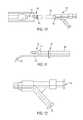
- FIG. 1is a top plan view of an implant in accordance with an embodiment of the present disclosure
- FIG. 2is a left plan view of the implant of FIG. 1 ;
- FIG. 3is a right plan view of the implant of FIG. 1 ;
- FIG. 4is a side plan view of the implant of FIG. 1 ;
- FIG. 5is a sectional view taken along line 5 - 5 in FIG. 4 ;
- FIG. 6is an enlarged view of a distal plug of the implant of FIG. 1 ;
- FIG. 7is an enlarged view of a proximal plug of the implant of FIG. 1 ;
- FIG. 8is a perspective view of an implant blank for forming the implant of FIG. 1 ;
- FIG. 9is a cut-away perspective view of the implant blank of FIG. 8 after the implant blank has been partially inverted;
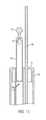
- FIG. 10is an inflation stylus inserted into the distal plug of the implant of FIG. 1 ;
- FIG. 11is a plan view of the distal end of the inflation stylus of FIG. 10 ;
- FIG. 12is a plan view of the proximal end of the inflation stylus of FIG. 10 ;
- FIG. 13is a sectional view of the distal end of another inflation stylus
- FIG. 14illustrates an annular reinforcing band for use with the implant of FIG. 1 , with a deflated implant located in the interior of the band;
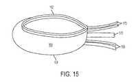
- FIG. 15illustrates the annular reinforcing band of FIG. 14 , with a filled implant
- FIG. 16illustrates the annular reinforcing band of FIG. 14 during deployment
- FIG. 17is a sectional view of the textile band of FIG. 13 ;
- FIG. 18illustrates a first step in implanting the implant assembly of FIG. 1 ;
- FIG. 19illustrates a second step in implanting the implant assembly of FIG. 1 ;
- FIG. 20illustrates a third step in implanting the implant assembly of FIG. 1 ;
- FIG. 21illustrates a fourth step in implanting the implant assembly of FIG. 1 ;
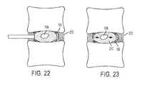
- FIG. 22illustrates a fifth step in implanting the implant assembly of FIG. 1 ;
- FIG. 23illustrates a sixth step in implanting the implant assembly of FIG. 1 .
- an embodiment of a minimally invasive or percutaneously deliverable spinal implant 100includes an outer fillable enclosure 102 and an inner fillable enclosure 104 .
- Outer fillable enclosure 102forms an outer enclosure 106
- inner fillable enclosure 104forms a inner chamber 108 .
- Inner chamber 108is encapsulated within outer chamber 102 .
- encapsulatedmeans that inner chamber 108 is substantially contained within outer chamber 106 such that inner chamber 108 is substantially surrounded on all sides by outer chamber 106 .
- Outer and inner fillable enclosures 102 , 104may be formed as a seamless, unitary piece of an elastomeric material, such as silicone rubber.
- compliant enclosures 102 , 104The use of an elastomeric material produces compliant outer and inner enclosures 102 , 104 . That is, the outer and inner enclosures 102 , 104 expand as the internal pressure increases when filled with a curable material.
- compliant enclosuresprovide certain advantages. Compliant enclosures accommodate the irregular, flat or discoid configuration of the nuclear space. Furthermore, compliant enclosures can help maintain an appropriate modulus of elasticity of the nuclear implant following elastomeric curing, and help preserve bio-mechanical mobility of the vertebral segment, and help allow unhindered deformation of the cured silicone component into the central void.
- the physical characteristics of inner and outer fillable enclosures 102 , 104may be tailored to provide desired physical outcomes.
- enclosures 102 , 104preferentially expand in a transverse plane.
- inner and outer fillable enclosures 102 , 104may be completely or partially semi-compliant or non-compliant (i.e., the do not expand or minimally expand as the internal pressure is increased).
- different parts of inner and outer fillable enclosures 102 , 104may be formed of different materials to provide different characteristics to enclosures 102 , 104 .
- Implant 100is preferably sized so that it can be inserted percutaneously or using minimally invasive surgery into a enucleated intervertebral disc cavity while deflated and then filled to fill the enucleated cavity.
- the exterior of filled implant 100is approximately 30 mm in length, 20 mm in width, and 10 mm in height, and the exterior of inner fillable enclosure 104 is approximately 9 mm long, 6 mm wide, and 6 mm thick.
- the enclosuredoes not expand significantly when it is filled (i.e., it is non-compliant or semi-compliant).
- the implantis filled so that the implant expands by approximately 100% (i.e., doubles in size) when implanted.
- the implantis filled so that the implant expands by more than 100% when implanted.
- Outer fillable enclosure 102has a first (or proximal) end 110 and a second (or distal) end 112 .
- Inner fillable enclosure 104has a first (or proximal) end 114 coupled to a proximal neck 116 .
- a second (or distal) end 118 of inner fillable enclosure 104is coupled to a distal neck 120 .
- An end portion 122 of distal neck portion 120is coupled to distal end 112 of outer fillable enclosure 102
- an end portion 124 of proximal neck 116is coupled to proximal end 110 of outer fillable enclosure 102 .
- end portion 124 of proximal neck 124is coupled to proximal end 110 of outer fillable enclosure 102 by forming them together as a unitary piece, as will be described in more detail below.
- Distal end 112 of outer fillable enclosure 102is inverted and bonded to end portion 122 of distal neck portion to form a substantially fluid tight seal. Coupling the enclosures together in this manner forms a substantially fluid tight outer chamber 106 .
- a proximal plug 126is located in the opening formed by proximal neck 116 .
- Proximal neck 116may have features, such as grooves 148 , for mating with matching features on proximal plug 126 to assist in locating proximal plug 126 .
- Proximal plug 126may be inserted into and bonded with proximal neck 116 .
- Proximal plug 126is adapted to mate with an inflation tip 192 of an inflation stylus 130 .
- a receptacle 132receives a first lumen 186 of inflation tip 192 to deliver material through aperture 134 into outer chamber 106 .
- Aperture 134may be a bottleneck in delivering material to outer chamber 106 , and may be formed as a skived hole to maximum the size of aperture 134 .
- Proximal plug 126may be made of silicone or another material which is compatible with enclosures 102 , 104 , and may be manufactured using conventional manufacturing techniques, such as injection molding.
- a locking featureto help prevent inadvertent dislodgment of inflation stylus 130 from proximal plug 126 is provided.
- a recess 136may be provided in proximal plug 126 and a mating feature (e.g., bead 152 , FIG. 13 ) may be provided on inflation tip 192 .
- An access lumen 138extends through proximal plug 126 to provide access to interior chamber 108 .
- receptacle 132 and access lumen 138can be arranged to prevent improper installation of inflation stylus 130 .
- a key 214is provided to physically prevent improper installation of inflation stylus 130 .
- Key 214may be used to control the depth of insertion of inflation tip 130 .
- positioning collar 190may be used to control the depth of insertion of inflation tip 130 .
- Access lumen 138is configured to remain open after implantation to serve as a vent for internal chamber 108 .
- a distal plug 140is disposed in distal neck 120 to seal the distal neck.
- Distal plug 140may have a cylindrical recess 142 on the interior side for receiving a distal end 200 of a contrast lumen 188 of inflation stylus 130 .
- Another cylindrical recess 146may be provided on distal plug 140 .
- Distal plug 140may be made of silicone or another material which is compatible with enclosures 102 , 104 , and may be manufactured using conventional manufacturing techniques, such as injection molding.
- annular reinforcing band 160may be provided to reinforce implant 100 .
- Annular reinforcing band 160is useful when a patient's annulus fibrosus is damaged.
- annular reinforcing band 160comprises a tubular, woven textile material.
- Annular reinforcing band 160is disposed around the perimeter of the lateral edges of implant 100 to minimize or prevent over inflation of the outer and inner balloons 102 , 104 circumferentially. Controlling circumferential expansion also encourages vertical expansion of balloons 102 , 104 to distract the adjacent vertebra and widen the disc space.
- the vertebral superior and inferior end platesconstrain the vertical expansion of the implant 100 .
- annular reinforcing band 160is formed of a woven material. In one embodiment, annular reinforcing band 160 uses an axial weave which minimizes or substantially prevents shortening of the band when it is expanded.
- U.S. Pat. No. 8,636,803 entitled Percutaneous Implantable Nuclear Implantdiscloses other suitable constructions of annular reinforcing band 160 , and is hereby incorporated by reference in its entirety for all purposes.
- One suitable material for annular reinforcing brand 160is ultra-high molecular weight polyethylene fiber, such as DYNEEMA® fiber available from Koninklijke DSM N.V., Heerleen, the Netherlands.
- Annular reinforcement band 160has a superior edge 162 , an inferior edge 164 , and a central zone 166 between superior and inferior edges 162 , 164 .
- One or more pull strings and control elementsare provided to help place annular reinforcement band during deployment of implant 100 .
- an inferior pull string 168 , a superior pull string 170 , and a control element 172are provided.
- Superior pull stringis placed in a pocket 176 or otherwise coupled to superior edge 162 of annular reinforcement band 160 .
- inferior pull string 168is placed in a pocket 176 or otherwise coupled to inferior edge 164 of annular reinforcement band 160 .
- Inferior and superior pull stringscan be used as a drawstring (i.e., pulled) during deployment to pull the edges of annular reinforcement band 160 inward, thereby helping to constrain and position implant 100 .
- Control element 172is disposed in central zone 166 of annular band 160 . If annular band 160 comprises a tubular material, then control element 172 is placed inside the tubular material. In other embodiments, control element 172 is placed in a pocket formed on annular reinforcing band 160 . Control element 172 may be a wire, such as a flat ribbon of nitinol, which runs around the perimeter of annular reinforcement band 160 . Control element 172 may be used to press annular reinforcement band 160 outward to an annulus fibrosus. Further details of the operation of control element 172 and pull strings 168 , 170 will be discussed below.
- inflation stylus 130may be used in conjunction with a delivery sheath to deliver implant 100 and annular reinforcement band 160 .
- Inflation stylus 130comprises a shaft 180 with a proximal end 182 and a distal end 184 .
- a first lumen 186 and a second lumen 188extend through shaft 180 .
- a positioning collar 190is provided to maintain first and second lumen 186 , 188 in a desired portion.
- the distal ends of first and second lumens 186 , 188form an inflation tip 192 which is configured to mate with proximal plug 126 .
- First (or silicone) lumen 186extends from proximal end 182 of inflation stylus 130 to distal end 184 of inflation stylus 130 .
- an aperture 194 at the distal end of first lumen 186is coincident with aperture 134 of proximal plug 126 to allow fluid communication between outer chamber 106 and first lumen 186 .
- Proximal end of lumen 186is provided with a connector 196 for connection to common inflation tools (such as syringes) known to those of skill in the art.
- a vent 198may be provided to allow air to exit silicone lumen 186 when silicone or another suitable material is delivered to outer chamber 106 .
- Vent 198may be large enough to allow air to freely move through it, while resisting more viscous fluids such as curable silicone.
- silicone lumenmeans a lumen for delivery of any desired fluid to outer chamber 106 , and can encompass materials other than silicone.
- Vent 198preferably extends through shaft 180 to vent to atmosphere at the proximal end of inflation stylus 130 .
- Second (or contrast) lumen 188extends from proximal end 182 of inflation stylus 130 to distal end 184 of inflation stylus 130 . Contrast lumen 188 extends out the proximal end of inflation stylus 130 . Preferably, contrast lumen 188 is independently movable with respect to inflation stylus 130 so that the position of the distal end 200 of contrast lumen 188 may be extended and withdrawn with respect to the distal end 184 of inflation stylus 130 . For delivery prior to implantation, contrast lumen 188 can extend through access lumen 138 and the distal tip of contrast lumen 188 can be positioned within recess 142 of distal plug 140 to hold it into place.
- Contrast lumen 188can be used to both deliver and remove fluids from inner chamber 108 .
- distal end 200 of contrast lumen 188is preformed into a shape which allows easier removal of fluid from inner chamber 108 .
- contrast lumen 188is preformed into a curved shape which allows easier access to the bottom of inner chamber 108 .
- the curved shapecombined with the ability to extend and withdraw contrast lumen 188 allows it to be adjusted when used to withdraw fluid from inner chamber 108 .
- contrast lumenshould be understood to mean a lumen for delivery of any desired fluid to inner chamber 108 , and can encompass materials other than contrast medium. Contrast medium may be used to ensure visibility under imaging, such as fluoroscopy.
- a delivery sheath 174comprises a lumen sized to fit over shaft 180 of inflation stylus 130 .
- implant 100is placed onto inflation tip 192 , and the assembled bodies are withdrawn into the distal end of delivery sheath 174 . If pull wires 168 , 170 and control element 172 are used, they may be placed through the lumen of the delivery sheath.
- implant 100may be formed by forming an implant blank 150 , which comprises outer fillable enclosure 102 coupled to inner fillable enclosure 104 .
- Implant blank 150may be manufactured using conventional manufacturing techniques, such as injection molding or dip molding. After implant blank 150 is formed, implant blank 150 is partially inverted to place inner fillable enclosure 104 into the interior of outer fillable enclosure 102 .
- Distal plug 140is inserted into distal neck 120
- proximal plug 126is inserted into proximal neck 116 . Additional details regarding one suitable manufacturing technique are disclosed in application 62/074,295, entitled “Percutaneous Implantable Nuclear Prosthesis,” which was filed on Nov. 4, 2014 and is hereby incorporated by reference in its entirety.
- fillable implant 100is particularly well suited for deployment using minimally invasive or percutaneous surgical techniques.
- the existing nucleus pulposusis removed by performing a discectomy while leaving annulus fibrosus 202 substantially intact.
- the discectomyis performed using minimally invasive surgical techniques, such as percutaneous techniques, which uses a cannula 208 to access the disc cavity 206 through a small opening in annulus fibrosus 202 .
- the disc cavityis accessed using a posterolateral approach through Kambin's triangle. An anterior approach may also be used.
- the annulotomy in the annulus fibrosusmay be created by penetrating the fibrosus annulus with a guide pin (e.g., a K-wire) and a series of increasing diameter dilators placed over the guide pin. Once the desired diameter is obtained, the access cannula 208 is placed over the largest diameter, and the dilator set is removed. This procedure spreads the fibrous bands of the annulus fibrosus to create an annulotomy without excising (i.e., removing) any tissue, which aids in the healing process.
- the fibrosusmay be stabbed with a scalpel to create vertical slit to gain access to the nucleus space.
- the physicianmay remove the existing disc using any suitable instruments (such as rongeurs).
- the physicianshould avoid violating the circumferential annulus or penetrating the superior and inferior vertebral end plates.
- the physicianmay monitor the progress of the discectomy by inserting a compliant imaging balloon into the disc space and inflating the imaging balloon with a contrast agent.
- the imaging ballooncomprises a modified implant comprising outer inflatable enclosure 102 without an inner inflatable enclosure.
- the imaging balloonalso serves as a trial implant to predict the volume, shape and placement of the final implant.
- annulus fibrosus 202 and vertebral end plates 204form a substantially empty enucleated disc cavity 206 ( FIG. 18 ).
- the implant 100which is loaded into a delivery sheath 174 , is placed into enucleated disc cavity 206 through cannula 208 . Typically, the implant will be delivered to the far end of the disc cavity. The delivery sheath 174 is then withdrawn to expose the implant 100 inside the enucleated disc cavity.
- control member 172is manipulated to press central zone 166 of annular reinforcing band 160 substantially flush against the inner surface of annulus fibrosus 202 .
- Pull strings 168 , 170may be pulled to tighten edges 162 , 164 of annular reinforcing band 160 and form a pocket for receiving implant 100 .
- Control member 172 and pull strings 168 , 170may include radiopaque features (such as platinum or nitinol coating) to aid in visualization under fluoroscopy.
- inner chamber 108is first filled with a fluid to a desired size.
- a substantially incompressible fluid 210is used, such as a contrast medium. Prior to inflating the inner chamber, air should be purged from the system using, for example, a vacuum locking syringe. Fluid 210 is delivered using contrast lumen 188 of inflation stylus 130 . The inflation pressure of the inner chamber 108 is selected to fill inner fillable enclosure 104 to a desired size.
- Inflation stylus 130is used to deliver a curable material 212 to outer chamber 106 .
- Curable material 212is preferably an elastomeric material, such as silicone rubber containing a radiopaque material (such as barium sulfate). It is not necessary to evacuate air from the outer chamber prior to inflation because of the included vent. Curable material 212 may be chosen so that it polymerizes with the material of inner and outer fillable enclosures 102 , 104 to form a unitary member. The modulus of elasticity and other characteristics of curable material 212 can be selected based upon patient specific parameters. For instance, younger, more active patients may require a firmer material than less mobile geriatric patients.
- curable material 212is allowed to cure.
- the curable materialcomprises curable silicone which cures in a short period of time, for example, less than 10 minutes, or less than 5 minutes.
- the use of shorter curing periodsmay help prevent the dissolution of solvent from the curable medium to the fillable enclosures which may occur with longer curing mediums. Such leaching of solvents may adversely affect the structural integrity of the fillable enclosures.
- substantially incompressible fluid 210is removed using contrast lumen 188 .
- contrast lumen 188may be moved and manipulated to remove as much incompressible fluid 210 as is desired.
- substantially all of fluid 210is removed; however, some fluid is likely to remain and it is not necessary to remove all fluid.
- inflation stylus 130can all be withdrawn through cannula 208 , and cannula 208 can be removed. If the optional annular reinforcing band is used, pull strings 168 , 170 , control member 172 are also withdrawn through cannula 208 .
- the implant 100comprises an annular ring of cured material 212 surrounding hollow interior chamber 108 .
- Interior chamber 108remains open to allow fluids to enter and exit, thereby functioning as a shock absorber.
- This structureallows for vertical and horizontal load stresses placed on the intervertebral disc space to be redirected inward, centrally toward interior chamber 108 (see direction arrows of FIG. 23 ) instead of outward.
- annular reinforcing band 160encourages tissue in-growth of native annulus fibrosus 202 , thereby providing reinforcement to native annulus fibrosus 202 .
Landscapes
- Health & Medical Sciences (AREA)
- Engineering & Computer Science (AREA)
- Biomedical Technology (AREA)
- Orthopedic Medicine & Surgery (AREA)
- Transplantation (AREA)
- Life Sciences & Earth Sciences (AREA)
- General Health & Medical Sciences (AREA)
- Heart & Thoracic Surgery (AREA)
- Animal Behavior & Ethology (AREA)
- Public Health (AREA)
- Veterinary Medicine (AREA)
- Neurology (AREA)
- Vascular Medicine (AREA)
- Cardiology (AREA)
- Oral & Maxillofacial Surgery (AREA)
- Physical Education & Sports Medicine (AREA)
- Chemical & Material Sciences (AREA)
- Dispersion Chemistry (AREA)
- Surgery (AREA)
- Nuclear Medicine, Radiotherapy & Molecular Imaging (AREA)
- Medical Informatics (AREA)
- Molecular Biology (AREA)
- Prostheses (AREA)
- Surgical Instruments (AREA)
- Materials For Medical Uses (AREA)
Abstract
Description
Claims (35)
Priority Applications (3)
| Application Number | Priority Date | Filing Date | Title |
|---|---|---|---|
| US15/254,282US10575967B2 (en) | 2015-09-01 | 2016-09-01 | Implantable nuclear prosthesis |
| US16/806,580US11576793B2 (en) | 2015-09-01 | 2020-03-02 | Implantable nuclear prosthesis |
| US18/168,475US20230218409A1 (en) | 2015-09-01 | 2023-02-13 | Implantable nuclear prosthesis |
Applications Claiming Priority (2)
| Application Number | Priority Date | Filing Date | Title |
|---|---|---|---|
| US201562212950P | 2015-09-01 | 2015-09-01 | |
| US15/254,282US10575967B2 (en) | 2015-09-01 | 2016-09-01 | Implantable nuclear prosthesis |
Related Child Applications (1)
| Application Number | Title | Priority Date | Filing Date |
|---|---|---|---|
| US16/806,580DivisionUS11576793B2 (en) | 2015-09-01 | 2020-03-02 | Implantable nuclear prosthesis |
Publications (2)
| Publication Number | Publication Date |
|---|---|
| US20170056195A1 US20170056195A1 (en) | 2017-03-02 |
| US10575967B2true US10575967B2 (en) | 2020-03-03 |
Family
ID=58097257
Family Applications (3)
| Application Number | Title | Priority Date | Filing Date |
|---|---|---|---|
| US15/254,282Active2037-07-22US10575967B2 (en) | 2015-09-01 | 2016-09-01 | Implantable nuclear prosthesis |
| US16/806,580Active2037-11-28US11576793B2 (en) | 2015-09-01 | 2020-03-02 | Implantable nuclear prosthesis |
| US18/168,475PendingUS20230218409A1 (en) | 2015-09-01 | 2023-02-13 | Implantable nuclear prosthesis |
Family Applications After (2)
| Application Number | Title | Priority Date | Filing Date |
|---|---|---|---|
| US16/806,580Active2037-11-28US11576793B2 (en) | 2015-09-01 | 2020-03-02 | Implantable nuclear prosthesis |
| US18/168,475PendingUS20230218409A1 (en) | 2015-09-01 | 2023-02-13 | Implantable nuclear prosthesis |
Country Status (10)
| Country | Link |
|---|---|
| US (3) | US10575967B2 (en) |
| EP (1) | EP3344156B1 (en) |
| JP (1) | JP6891176B2 (en) |
| KR (1) | KR102607758B1 (en) |
| CN (1) | CN108348227B (en) |
| AU (1) | AU2016315964B2 (en) |
| CA (1) | CA2997117A1 (en) |
| ES (1) | ES2774513T3 (en) |
| PL (1) | PL3344156T3 (en) |
| WO (1) | WO2017040734A1 (en) |
Families Citing this family (11)
| Publication number | Priority date | Publication date | Assignee | Title |
|---|---|---|---|---|
| US20140277467A1 (en) | 2013-03-14 | 2014-09-18 | Spinal Stabilization Technologies, Llc | Prosthetic Spinal Disk Nucleus |
| KR102464886B1 (en) | 2014-11-04 | 2022-11-08 | 스파이널 스태빌라이제이션 테크놀로지스, 엘엘씨 | Percutaneous implantable nuclear prosthesis |
| WO2016073587A1 (en) | 2014-11-04 | 2016-05-12 | Spinal Stabilization Technologies Llc | Percutaneous implantable nuclear prosthesis |
| JP6891176B2 (en) | 2015-09-01 | 2021-06-18 | スパイナル スタビライゼーション テクノロジーズ リミテッド ライアビリティ カンパニー | Implantable nucleus pulposus prosthesis |
| US10285825B2 (en)* | 2016-04-07 | 2019-05-14 | Howmedica Osteonics Corp. | Surgical insertion instruments |
| EP3456297B1 (en) | 2017-09-15 | 2023-10-04 | Howmedica Osteonics Corp. | Instruments for expandable interbody implants |
| CA3111639A1 (en)* | 2018-09-04 | 2020-05-28 | Spinal Stabilization Technologies, Llc | Implantable nuclear prosthesis, kits, and related methods |
| US11129727B2 (en) | 2019-03-29 | 2021-09-28 | Medos International Sari | Inflatable non-distracting intervertebral implants and related methods |
| US11376131B2 (en)* | 2020-04-07 | 2022-07-05 | Ethicon, Inc. | Cortical rim-supporting interbody device and method |
| CN112535556B (en)* | 2020-11-02 | 2022-04-08 | 淮阴工学院 | Air bag type artificial cervical intervertebral disc prosthesis |
| CN113855230B (en)* | 2021-09-26 | 2023-07-28 | 武汉大学中南医院 | Human tissue cavity modeling device and method |
Citations (232)
| Publication number | Priority date | Publication date | Assignee | Title |
|---|---|---|---|---|
| US3875595A (en) | 1974-04-15 | 1975-04-08 | Edward C Froning | Intervertebral disc prosthesis and instruments for locating same |
| US4187390A (en) | 1970-05-21 | 1980-02-05 | W. L. Gore & Associates, Inc. | Porous products and process therefor |
| US4478898A (en) | 1982-06-04 | 1984-10-23 | Junkosha Co., Ltd. | Laminated porous polytetrafluoroethylene tube and its process of manufacture |
| US4517979A (en)* | 1983-07-14 | 1985-05-21 | Cordis Corporation | Detachable balloon catheter |
| US4619641A (en) | 1984-11-13 | 1986-10-28 | Mount Sinai School Of Medicine Of The City University Of New York | Coaxial double lumen anteriovenous grafts |
| US4743480A (en) | 1986-11-13 | 1988-05-10 | W. L. Gore & Associates, Inc. | Apparatus and method for extruding and expanding polytetrafluoroethylene tubing and the products produced thereby |
| US5123926A (en) | 1991-02-22 | 1992-06-23 | Madhavan Pisharodi | Artificial spinal prosthesis |
| US5152782A (en) | 1989-05-26 | 1992-10-06 | Impra, Inc. | Non-porous coated ptfe graft |
| US5181921A (en) | 1990-05-25 | 1993-01-26 | Kaken Co., Ltd. | Detachable balloon with two self-sealing valves |
| US5192310A (en) | 1991-09-16 | 1993-03-09 | Atrium Medical Corporation | Self-sealing implantable vascular graft |
| US5192326A (en) | 1990-12-21 | 1993-03-09 | Pfizer Hospital Products Group, Inc. | Hydrogel bead intervertebral disc nucleus |
| US5437661A (en) | 1994-03-23 | 1995-08-01 | Rieser; Bernhard | Method for removal of prolapsed nucleus pulposus material on an intervertebral disc using a laser |
| US5439464A (en) | 1993-03-09 | 1995-08-08 | Shapiro Partners Limited | Method and instruments for performing arthroscopic spinal surgery |
| US5466509A (en) | 1993-01-15 | 1995-11-14 | Impra, Inc. | Textured, porous, expanded PTFE |
| US5571189A (en) | 1994-05-20 | 1996-11-05 | Kuslich; Stephen D. | Expandable fabric implant for stabilizing the spinal motion segment |
| US5628786A (en) | 1995-05-12 | 1997-05-13 | Impra, Inc. | Radially expandable vascular graft with resistance to longitudinal compression and method of making same |
| US5645597A (en) | 1995-12-29 | 1997-07-08 | Krapiva; Pavel I. | Disc replacement method and apparatus |
| US5674295A (en) | 1994-10-17 | 1997-10-07 | Raymedica, Inc. | Prosthetic spinal disc nucleus |
| US5702449A (en) | 1995-06-07 | 1997-12-30 | Danek Medical, Inc. | Reinforced porous spinal implants |
| US5752969A (en) | 1993-06-17 | 1998-05-19 | Sofamor S.N.C. | Instrument for the surgical treatment of an intervertebral disc by the anterior route |
| US5827327A (en) | 1994-09-23 | 1998-10-27 | Impra, Inc. | Carbon containing vascular graft and method of making same |
| US5860425A (en) | 1991-12-03 | 1999-01-19 | Boston Scientific Technology, Inc. | Bladder neck suspension procedure |
| US5865845A (en) | 1996-03-05 | 1999-02-02 | Thalgott; John S. | Prosthetic intervertebral disc |
| US5879366A (en) | 1996-12-20 | 1999-03-09 | W.L. Gore & Associates, Inc. | Self-expanding defect closure device and method of making and using |
| US5888220A (en) | 1994-05-06 | 1999-03-30 | Advanced Bio Surfaces, Inc. | Articulating joint repair |
| US5888226A (en) | 1997-11-12 | 1999-03-30 | Rogozinski; Chaim | Intervertebral prosthetic disc |
| US5890268A (en) | 1995-09-07 | 1999-04-06 | Case Western Reserve University | Method of forming closed cell metal composites |
| US5910277A (en) | 1996-05-17 | 1999-06-08 | Nitto Denko Corporation | Process of making a porous PTFE membrane |
| US5928284A (en) | 1998-07-09 | 1999-07-27 | Mehdizadeh; Hamid M. | Disc replacement prosthesis |
| US5935147A (en) | 1991-11-08 | 1999-08-10 | Kensey Nash Corporation | Hemostatic puncture closure system and method of use |
| US5954767A (en) | 1993-09-13 | 1999-09-21 | C.R. Bard Inc. | Curved prosthetic mesh and its method of manufacture |
| US5972022A (en) | 1994-09-26 | 1999-10-26 | Ethicon, Inc. | Tissue attachment device having elastomeric section |
| US5976174A (en) | 1997-12-15 | 1999-11-02 | Ruiz; Carlos E. | Medical hole closure device and methods of use |
| US5981826A (en) | 1997-05-05 | 1999-11-09 | Georgia Tech Research Corporation | Poly(vinyl alcohol) cryogel |
| US5990378A (en) | 1995-05-25 | 1999-11-23 | Bridport Gundry (Uk) Limited | Textile surgical implants |
| US6001130A (en) | 1994-11-14 | 1999-12-14 | Bryan; Vincent | Human spinal disc prosthesis with hinges |
| US6001125A (en) | 1996-01-22 | 1999-12-14 | Meadox Medicals, Inc. | PTFE vascular prosthesis and method of manufacture |
| US6007575A (en) | 1997-06-06 | 1999-12-28 | Samuels; Shaun Laurence Wilkie | Inflatable intraluminal stent and method for affixing same within the human body |
| US6007570A (en) | 1996-08-13 | 1999-12-28 | Oratec Interventions, Inc. | Apparatus with functional element for performing function upon intervertebral discs |
| US6019793A (en) | 1996-10-21 | 2000-02-01 | Synthes | Surgical prosthetic device |
| US6126682A (en) | 1996-08-13 | 2000-10-03 | Oratec Interventions, Inc. | Method for treating annular fissures in intervertebral discs |
| US6127597A (en) | 1997-03-07 | 2000-10-03 | Discotech N.V. | Systems for percutaneous bone and spinal stabilization, fixation and repair |
| US6140452A (en) | 1994-05-06 | 2000-10-31 | Advanced Bio Surfaces, Inc. | Biomaterial for in situ tissue repair |
| US6146419A (en) | 1999-05-13 | 2000-11-14 | Board Of Trustees Of The University | Method for forming a hollow prosthesis |
| US6180848B1 (en) | 1997-08-27 | 2001-01-30 | Ethicon, Inc. | Prosthesis obturating device for the obturation of a hernial canal |
| US6183518B1 (en) | 1999-02-22 | 2001-02-06 | Anthony C. Ross | Method of replacing nucleus pulposus and repairing the intervertebral disk |
| US6206921B1 (en) | 1999-02-22 | 2001-03-27 | Peter A. Guagliano | Method of replacing nucleus pulposus and repairing the intervertebral disk |
| US6224630B1 (en) | 1998-05-29 | 2001-05-01 | Advanced Bio Surfaces, Inc. | Implantable tissue repair device |
| US6248131B1 (en) | 1994-05-06 | 2001-06-19 | Advanced Bio Surfaces, Inc. | Articulating joint repair |
| US6264695B1 (en) | 1999-09-30 | 2001-07-24 | Replication Medical, Inc. | Spinal nucleus implant |
| US6332894B1 (en) | 2000-03-07 | 2001-12-25 | Zimmer, Inc. | Polymer filled spinal fusion cage |
| US6344054B1 (en) | 1996-09-20 | 2002-02-05 | Juan Carlos Parodi | Endoluminal prosthesis comprising stent and overlying graft cover, and system and method for deployment thereof |
| US20020026244A1 (en) | 2000-08-30 | 2002-02-28 | Trieu Hai H. | Intervertebral disc nucleus implants and methods |
| US6361637B2 (en) | 1995-12-14 | 2002-03-26 | Gore Enterprise Holdings, Inc. | Method of making a kink resistant stent-graft |
| US6375682B1 (en) | 2001-08-06 | 2002-04-23 | Lewis W. Fleischmann | Collapsible, rotatable and expandable spinal hydraulic prosthetic device |
| US6390992B1 (en) | 1995-05-05 | 2002-05-21 | Advanced Cardiovascular Systems, Inc. | Intraluminal device with lubricious surface |
| US6395032B1 (en) | 1998-12-11 | 2002-05-28 | Dimso (Distribution Medicale Du Sud-Ouest) | Intervertebral disc prosthesis with liquid chamber |
| US6398803B1 (en) | 1999-02-02 | 2002-06-04 | Impra, Inc., A Subsidiary Of C.R. Bard, Inc. | Partial encapsulation of stents |
| US20020068975A1 (en) | 2000-06-23 | 2002-06-06 | Teitelbaum George P. | Formable orthopedic fixation system with cross linking |
| US6402750B1 (en) | 2000-04-04 | 2002-06-11 | Spinlabs, Llc | Devices and methods for the treatment of spinal disorders |
| US6419704B1 (en) | 1999-10-08 | 2002-07-16 | Bret Ferree | Artificial intervertebral disc replacement methods and apparatus |
| US6428576B1 (en) | 1999-04-16 | 2002-08-06 | Endospine, Ltd. | System for repairing inter-vertebral discs |
| US6436143B1 (en) | 1999-02-22 | 2002-08-20 | Anthony C. Ross | Method and apparatus for treating intervertebral disks |
| US6443988B2 (en) | 1994-05-06 | 2002-09-03 | Disc Dynamics, Inc. | Mold apparatus and kit for in situ tissue repair |
| US20020147497A1 (en) | 2001-04-06 | 2002-10-10 | Integrated Vascular Systems, Inc. | Methods for treating spinal discs |
| US20020151979A1 (en) | 1999-08-18 | 2002-10-17 | Lambrecht Greg H. | Devices and method for nucleus pulposus augmentation and retention |
| US6482234B1 (en) | 2000-04-26 | 2002-11-19 | Pearl Technology Holdings, Llc | Prosthetic spinal disc |
| US20020198588A1 (en) | 1999-01-22 | 2002-12-26 | Armstrong Joseph R. | Covered endoprosthesis and delivery system |
| US20030028251A1 (en) | 2001-07-30 | 2003-02-06 | Mathews Hallett H. | Methods and devices for interbody spinal stabilization |
| US20030040772A1 (en) | 1999-02-01 | 2003-02-27 | Hideki Hyodoh | Delivery devices |
| US6527804B1 (en) | 1998-12-11 | 2003-03-04 | Dimso (Distribution Medicale Du Sud-Quest) | Intervertebral disk prosthesis |
| US20030114917A1 (en) | 2001-12-14 | 2003-06-19 | Holloway Ken A. | Layered stent-graft and methods of making the same |
| US6582466B1 (en) | 1998-12-11 | 2003-06-24 | Stryker Spine | Intervertebral disc prosthesis with reduced friction |
| US6596008B1 (en) | 1997-07-15 | 2003-07-22 | Parviz Kambin | Method and instruments for percutaneous arthroscopic disc removal, bone biopsy and fixation of the vertebral |
| US20030153976A1 (en) | 1999-10-20 | 2003-08-14 | Cauthen Joseph C. | Spinal disc annulus reconstruction method and spinal disc annulus stent |
| US6632235B2 (en)* | 2001-04-19 | 2003-10-14 | Synthes (U.S.A.) | Inflatable device and method for reducing fractures in bone and in treating the spine |
| US20030199979A1 (en) | 2001-10-02 | 2003-10-23 | Rex Medical | Spinal implant and method of use |
| US6645248B2 (en) | 2001-08-24 | 2003-11-11 | Sulzer Orthopedics Ltd. | Artificial intervertebral disc |
| US6673103B1 (en) | 1999-05-20 | 2004-01-06 | Scimed Life Systems, Inc. | Mesh and stent for increased flexibility |
| US6689125B1 (en) | 2000-04-04 | 2004-02-10 | Spinalabs, Llc | Devices and methods for the treatment of spinal disorders |
| US6712853B2 (en) | 2000-12-15 | 2004-03-30 | Spineology, Inc. | Annulus-reinforcing band |
| US6733532B1 (en) | 1998-12-11 | 2004-05-11 | Stryker Spine | Intervertebral disc prosthesis with improved mechanical behavior |
| US6733533B1 (en) | 2002-11-19 | 2004-05-11 | Zimmer Technology, Inc. | Artificial spinal disc |
| US6780497B1 (en) | 1999-08-05 | 2004-08-24 | Gore Enterprise Holdings, Inc. | Surface modified expanded polytetrafluoroethylene devices and methods of producing the same |
| US20040186471A1 (en) | 2002-12-07 | 2004-09-23 | Sdgi Holdings, Inc. | Method and apparatus for intervertebral disc expansion |
| US20040220672A1 (en) | 2003-05-03 | 2004-11-04 | Shadduck John H. | Orthopedic implants, methods of use and methods of fabrication |
| US20040230309A1 (en) | 2003-02-14 | 2004-11-18 | Depuy Spine, Inc. | In-situ formed intervertebral fusion device and method |
| US20050004578A1 (en) | 1999-08-18 | 2005-01-06 | Lambrecht Gregory H. | Apparatus delivery in an intervertebral disc |
| US20050015150A1 (en) | 2003-07-17 | 2005-01-20 | Lee Casey K. | Intervertebral disk and nucleus prosthesis |
| US6852223B2 (en) | 2001-10-31 | 2005-02-08 | Yeu Ming Tai Chemical Industrial Co., Ltd. | Asymmetric porous polytetrafluoroethylene membrane and process for preparing the same |
| US6852095B1 (en) | 1997-07-09 | 2005-02-08 | Charles D. Ray | Interbody device and method for treatment of osteoporotic vertebral collapse |
| US20050055099A1 (en) | 2003-09-09 | 2005-03-10 | Ku David N. | Flexible spinal disc |
| US6866681B2 (en) | 1996-11-20 | 2005-03-15 | Jacques-Phillippe Laboureau | Pre-adjusted prosthetic ligament and method of manufacture |
| US20050065609A1 (en) | 2001-11-19 | 2005-03-24 | Douglas Wardlaw | Intervertebral disc prosthesis |
| US20050090901A1 (en) | 2001-12-05 | 2005-04-28 | Armin Studer | Intervertebral disk prosthesis or nucleus replacement prosthesis |
| US6893466B2 (en) | 2000-08-30 | 2005-05-17 | Sdgi Holdings, Inc. | Intervertebral disc nucleus implants and methods |
| US6893465B2 (en) | 2003-03-31 | 2005-05-17 | Shi, Tain-Yew | Vividly simulated prosthetic intervertebral disc |
| US20050119752A1 (en) | 2003-11-19 | 2005-06-02 | Synecor Llc | Artificial intervertebral disc |
| US20050137675A1 (en) | 2000-12-19 | 2005-06-23 | Alexander Dubson | Vascular prosthesis and method for production thereof |
| US6932843B2 (en) | 2002-09-25 | 2005-08-23 | Medicinelodge, Inc. | Apparatus and method for the in-situ formation of a structural prosthesis |
| US6936070B1 (en) | 2001-01-17 | 2005-08-30 | Nabil L. Muhanna | Intervertebral disc prosthesis and methods of implantation |
| US20050197702A1 (en) | 2002-08-15 | 2005-09-08 | Coppes Justin K. | Intervertebral disc implant |
| US6958077B2 (en) | 2003-07-29 | 2005-10-25 | Loubert Suddaby | Inflatable nuclear prosthesis |
| US6969404B2 (en) | 1999-10-08 | 2005-11-29 | Ferree Bret A | Annulus fibrosis augmentation methods and apparatus |
| US6969405B2 (en) | 2003-04-23 | 2005-11-29 | Loubert Suddaby | Inflatable intervertebral disc replacement prosthesis |
| US6984246B2 (en) | 2003-06-06 | 2006-01-10 | Tain-Yew Shi | Artificial intervertebral disc flexibly oriented by spring-reinforced bellows |
| US7004971B2 (en) | 2002-12-31 | 2006-02-28 | Depuy Acromed, Inc. | Annular nucleus pulposus replacement |
| US7008427B2 (en) | 2000-05-25 | 2006-03-07 | Orthoplex, Llc | Inter-vertebral disc prosthesis for rachis through anterior surgery thereof |
| WO2006060482A2 (en) | 2004-12-01 | 2006-06-08 | The Regents Of The University Of California | Systems, devices and methods of treatment of intervertebral disorders |
| US20060247780A1 (en) | 2005-04-27 | 2006-11-02 | Bert Jeffrey K | Expandable artificial disc and associated methods and instrumentation |
| US7133001B2 (en) | 2003-11-03 | 2006-11-07 | Toyon Research Corporation | Inflatable-collapsible transreflector antenna |
| US20060253132A1 (en) | 2005-05-06 | 2006-11-09 | International Business Machines Corporation | System and devices for the repair of a vertebral disc defect |
| US20060265077A1 (en)* | 2005-02-23 | 2006-11-23 | Zwirkoski Paul A | Spinal repair |
| US20060293749A1 (en) | 2005-06-02 | 2006-12-28 | Zimmer Spine, Inc. | Interbody fusion ring and method of using the same |
| US7156877B2 (en)* | 2001-06-29 | 2007-01-02 | The Regents Of The University Of California | Biodegradable/bioactive nucleus pulposus implant and method for treating degenerated intervertebral discs |
| US7156861B2 (en) | 1997-08-15 | 2007-01-02 | Kyphon Inc. | Expandable structures for deployment in interior body regions |
| US7182783B2 (en) | 2005-04-25 | 2007-02-27 | Sdgi Holdings, Inc. | Selectively expandable composite structures for spinal arthroplasty |
| US20070060924A1 (en) | 2005-08-29 | 2007-03-15 | Taeyon Medical Co., Ltd. | Recovery device for balloon kyphoplasty |
| US20070073402A1 (en) | 2005-08-26 | 2007-03-29 | Edward Vresilovic | Hydrogel balloon prosthesis for nucleus pulposus |
| US7201776B2 (en) | 1999-10-08 | 2007-04-10 | Ferree Bret A | Artificial intervertebral disc replacements with endplates |
| US7201751B2 (en) | 1997-01-02 | 2007-04-10 | St. Francis Medical Technologies, Inc. | Supplemental spine fixation device |
| US7204851B2 (en) | 2000-08-30 | 2007-04-17 | Sdgi Holdings, Inc. | Method and apparatus for delivering an intervertebral disc implant |
| US20070093906A1 (en) | 2005-10-26 | 2007-04-26 | Zimmer Spine, Inc. | Nucleus implant and method |
| US20070135921A1 (en) | 2005-12-09 | 2007-06-14 | Park Kee B | Surgical implant |
| US20070150061A1 (en) | 2005-12-27 | 2007-06-28 | Sdgi Holdings, Inc. | Intervertebral disc augmentation and rehydration with superabsorbent polymers |
| US20070162136A1 (en) | 2005-12-22 | 2007-07-12 | O'neil Michael | Nucleus pulposus trial device and technique |
| US20070168042A1 (en) | 2006-01-13 | 2007-07-19 | Hudgins Robert G | Devices and methods for disc replacement |
| US20070173940A1 (en) | 2006-01-18 | 2007-07-26 | Zimmer Spine, Inc. | Vertebral fusion device and method |
| US20070173935A1 (en) | 2005-10-28 | 2007-07-26 | O'neil Michael J | Nucleus pulposus augmentation pretreatment technique |
| WO2007087404A2 (en) | 2006-01-24 | 2007-08-02 | Hydrocision, Inc. | Liquid jet surgical instrument having a distal end with a selectively controllable shape |
| US20070213732A1 (en) | 2006-03-13 | 2007-09-13 | The Johns Hopkins University | Orthopedic Screw System |
| US7273497B2 (en) | 1999-05-28 | 2007-09-25 | Anova Corp. | Methods for treating a defect in the annulus fibrosis |
| US20070255406A1 (en) | 2006-04-27 | 2007-11-01 | Sdgi Holdings, Inc. | Devices, apparatus, and methods for bilateral approach to disc augmentation |
| US20070255285A1 (en) | 2006-04-27 | 2007-11-01 | Warsaw Orthopedic, Inc. | Devices, Apparatus, and Methods for Disc Augmentation |
| US7297158B2 (en) | 2004-06-14 | 2007-11-20 | Thoratec Corporation | Multilayer composite vascular access graft |
| US20070270953A1 (en) | 2006-03-29 | 2007-11-22 | Sdgi Holdings, Inc. | Transformable spinal implants and methods of use |
| US20070288095A1 (en) | 2006-06-12 | 2007-12-13 | Anthony Wirtel | Inflatable multi-chambered devices and methods of treatment using the same |
| US7309359B2 (en) | 2003-08-21 | 2007-12-18 | Warsaw Orthopedic, Inc. | Allogenic/xenogenic implants and methods for augmenting or repairing intervertebral discs |
| US20080058932A1 (en) | 2006-07-26 | 2008-03-06 | Warsaw Orthopedic Inc. | Rigidization-on-command orthopedic devices and methods |
| US20080119943A1 (en) | 2006-11-16 | 2008-05-22 | Armstrong Joseph R | Stent having flexibly connected adjacent stent elements |
| US20080132934A1 (en)* | 1994-01-26 | 2008-06-05 | Kyphon, Inc. | Systems and methods treating a vertebral body related applications |
| US20080154373A1 (en) | 2006-12-21 | 2008-06-26 | Warsaw Orthopedic, Inc. | Curable orthopedic implant devices configured to be hardened after placement in vivo |
| US20080154367A1 (en) | 2006-12-21 | 2008-06-26 | Warsaw Orthopedic, Inc. | Methods for positioning a load-bearing component of an orthopedic implant device by inserting a malleable device that hardens in vivo |
| US20080154368A1 (en) | 2006-12-21 | 2008-06-26 | Warsaw Orthopedic, Inc. | Curable orthopedic implant devices configured to harden after placement in vivo by application of a cure-initiating energy before insertion |
| US20080195210A1 (en) | 2005-03-01 | 2008-08-14 | Columna Pty Ltd | Intervertebral Disc Restoration |
| US20080288073A1 (en) | 2007-05-17 | 2008-11-20 | Depuy Spine, Inc. | Self-Distracting Cage |
| US20080288074A1 (en) | 2007-05-15 | 2008-11-20 | O'neil Michael J | Internally reinforced elastomeric intervertebral disc implants |
| US20090012618A1 (en) | 2006-05-24 | 2009-01-08 | Disc Dynamics, Inc. | Retention structure for in situ formation of an intervertebral prosthesis |
| US20090030399A1 (en)* | 2007-07-23 | 2009-01-29 | Kamshad Raiszadeh | Drug Delivery Device and Method |
| US20090076610A1 (en) | 2007-03-31 | 2009-03-19 | Spinal Kinetics, Inc. | Prosthetic Intervertebral Discs Having Balloon-Based Fillable Cores That are Implantable By Minimally Invasive Surgical Techniques |
| US20090076609A1 (en) | 2007-03-31 | 2009-03-19 | Spinal Kinetics, Inc. | Prosthetic Intervertebral Discs with Slotted End Plates That are Implantable By Minimally Invasive, Posterior Approach, Surgical Techniques |
| US20090082870A1 (en) | 2007-09-20 | 2009-03-26 | Osman Said G | Transpedicular, extrapedicular and transcorporeal partial disc replacement |
| US20090105823A1 (en) | 2004-09-30 | 2009-04-23 | Synecor, Llc | Artificial intervertebral disc nucleus |
| US20090112221A1 (en) | 2007-10-25 | 2009-04-30 | Disc Dynamics, Inc. | System and method for measuring the shape of internal body cavities |
| US20090112323A1 (en)* | 2007-10-29 | 2009-04-30 | Zimmer Spine, Inc. | Minimally invasive interbody device and method |
| US20090118833A1 (en) | 2007-11-05 | 2009-05-07 | Zimmer Spine, Inc. | In-situ curable interspinous process spacer |
| US20090163994A1 (en) | 2007-12-21 | 2009-06-25 | Boston Scientific Scimed, Inc. | Flexible Stent-Graft Device Having Patterned Polymeric Coverings |
| US7556650B2 (en) | 2004-06-29 | 2009-07-07 | Spine Wave, Inc. | Methods for injecting a curable biomaterial into an intervertebral space |
| US20090222093A1 (en)* | 2008-02-28 | 2009-09-03 | Warsaw Orthopedic, Inc. | Nucleus Implant and Method of Installing Same |
| US20090240341A1 (en) | 2005-08-15 | 2009-09-24 | Columna Pty Ltd | Tissue prosthesis and a method of, and equipment for, forming a tissue prosthesis |
| US7618461B2 (en) | 2000-08-30 | 2009-11-17 | Warsaw Orthopedic, Inc. | Composite intervertebral disc implants and methods for forming the same |
| US20090299476A1 (en) | 2006-05-19 | 2009-12-03 | Ashish Diwan | Tissue prosthesis |
| US7632294B2 (en) | 2003-09-29 | 2009-12-15 | Promethean Surgical Devices, Llc | Devices and methods for spine repair |
| US7632291B2 (en) | 2003-06-13 | 2009-12-15 | Trivascular2, Inc. | Inflatable implant |
| US20100030216A1 (en) | 2008-07-30 | 2010-02-04 | Arcenio Gregory B | Discectomy tool having counter-rotating nucleus disruptors |
| US7722612B2 (en) | 2004-05-19 | 2010-05-25 | Sintea Biotech S.P.A. | Devices, kit and method for kyphoplasty |
| US7731753B2 (en) | 2005-09-01 | 2010-06-08 | Spinal Kinetics, Inc. | Prosthetic intervertebral discs |
| US20100191335A1 (en) | 2005-11-21 | 2010-07-29 | Nicast Ltd. | Spinal nucleus prosthesis device |
| US20100193999A1 (en) | 2009-01-16 | 2010-08-05 | Anneaux Bruce L | Electrospinning of ptfe with high viscosity materials |
| US20100256766A1 (en)* | 2009-04-07 | 2010-10-07 | Hibri Nadi S | Percutaneous Implantable Nuclear Prosthesis |
| US20100256619A1 (en) | 2003-05-30 | 2010-10-07 | Warsaw Orthopedic, Inc. | Methods and Devices for Transpedicular Discectomy |
| US20100292798A1 (en) | 2007-10-19 | 2010-11-18 | Gianluca Maestretti | Hemi-prosthesis |
| US7842055B2 (en) | 1998-04-10 | 2010-11-30 | Ev3 Endovascular, Inc. | Neuro thrombectomy catheter |
| US7896920B2 (en) | 2000-10-24 | 2011-03-01 | Cryolife, Inc. | In situ bioprosthetic filler and method, particularly for the in situ formation of vertebral disc bioprosthetics |
| US20110093076A1 (en) | 2006-12-28 | 2011-04-21 | Reo Michael L | Prosthetic lumbar disc assembly having natural biomechanical movement |
| US7931689B2 (en) | 2000-02-28 | 2011-04-26 | Spineology Inc. | Method and apparatus for treating a vertebral body |
| US7947079B2 (en) | 1999-05-07 | 2011-05-24 | University Of Virginia Patent Foundation | Method and system for fusing a spinal region |
| US20110125158A1 (en) | 2008-05-01 | 2011-05-26 | Ashish Dhar Diwan | Systems, methods and apparatuses for formation and insertion of tissue prostheses |
| US7972351B2 (en) | 2004-07-13 | 2011-07-05 | Boston Scientific Scimed, Inc. | Balloon folding design and method and apparatus for making balloons |
| US20110190753A1 (en) | 2004-04-23 | 2011-08-04 | Leonard Edward Forrest | Device and method treatment or evacuation of intervertebral disc |
| US7993351B2 (en) | 2002-07-24 | 2011-08-09 | Pressure Products Medical Supplies, Inc. | Telescopic introducer with a compound curvature for inducing alignment and method of using the same |
| US20110196499A1 (en) | 1998-08-14 | 2011-08-11 | Kyphon Sarl | Systems and methods for treating vertebral bodies |
| US7998210B2 (en) | 2006-04-27 | 2011-08-16 | Warsaw Orthopedic, Inc. | Expandable intervertebral spacers and methods of use |
| US8012210B2 (en) | 2004-01-16 | 2011-09-06 | Warsaw Orthopedic, Inc. | Implant frames for use with settable materials and related methods of use |
| US8012211B2 (en) | 2002-11-05 | 2011-09-06 | Spineology, Inc. | Semi-biological intervertebral disc replacement system |
| US20110264224A1 (en) | 1999-05-28 | 2011-10-27 | Anova Corporation | Methods and apparatus for treating disc herniation and preventing the extrusion of interbody bone graft |
| US20110282418A1 (en) | 2010-05-14 | 2011-11-17 | Ameliomed, Llc | Methods and devices for cooling spinal tissue |
| US8066758B2 (en) | 2005-06-17 | 2011-11-29 | C. R. Bard, Inc. | Vascular graft with kink resistance after clamping |
| US8083800B2 (en) | 2006-07-21 | 2011-12-27 | Warsaw Orthopedic, Inc. | Expandable vertebral implant and methods of use |
| US20110319996A1 (en) | 2008-12-22 | 2011-12-29 | Synthes Usa, Llc | Expandable vertebral body replacement device and method |
| US8100978B2 (en) | 2007-04-01 | 2012-01-24 | Spinal Kinetics Inc. | Prosthetic intervertebral discs having expandable cores that are implantable using minimally invasive surgical techniques |
| US8123808B2 (en) | 2009-04-16 | 2012-02-28 | Warsaw Orthopedic, Inc. | Vertebral endplate connection implant and method |
| US8133250B2 (en) | 2001-09-28 | 2012-03-13 | Boston Scientific Scimed, Inc. | Medical devices comprising nanocomposites |
| US8142489B2 (en) | 1995-03-01 | 2012-03-27 | Boston Scientific Scimed, Inc. | Flexible and expandable stent |
| US20120089229A1 (en) | 2006-02-13 | 2012-04-12 | Lanx, Inc. | Method and apparatus for intervertebral disc support and repair |
| US20120089227A1 (en) | 2009-06-18 | 2012-04-12 | Peter Jarzem | Hollow highly-expandable prosthetic vertebral body |
| KR20120040309A (en) | 2010-10-19 | 2012-04-27 | 인하대학교 산학협력단 | Ballon anchor reinforcing pedicle screw in osteoporotic spine |
| US20120165941A1 (en) | 2010-12-22 | 2012-06-28 | Illuminoss Medical, Inc. | Systems and methods for treating conditions and diseases of the spine |
| US8246682B2 (en) | 2008-12-16 | 2012-08-21 | Depuy Spine, Inc. | Methods and devices for expanding a spinal canal using balloons |
| US8292961B2 (en) | 2008-01-23 | 2012-10-23 | Osman Said G | Biologic vertebral reconstruction |
| US20120277862A1 (en) | 2008-04-04 | 2012-11-01 | Clariance | Nuclear implant |
| US8317864B2 (en) | 2004-10-20 | 2012-11-27 | The Board Of Trustees Of The Leland Stanford Junior University | Systems and methods for posterior dynamic stabilization of the spine |
| US20120316648A1 (en) | 1999-08-18 | 2012-12-13 | Intrinsic Therapeutics, Inc. | Intervertebral disc reinforcement systems |
| US8337556B2 (en) | 2000-06-23 | 2012-12-25 | Sdgi Holdings, Inc. | Curable media for implantable medical device |
| US20130004586A1 (en) | 2011-06-24 | 2013-01-03 | Vachon David J | Biologically Efficacious Compositions, Articles of Manufacture and Processes for Producing and/or Using Same |
| US8349013B2 (en) | 1997-01-02 | 2013-01-08 | Kyphon Sarl | Spine distraction implant |
| US8377131B2 (en) | 2007-06-06 | 2013-02-19 | Spirit Spine Holdings Corporation, Inc. | Medical implant |
| US8377136B2 (en) | 2009-04-20 | 2013-02-19 | Warsaw Orthopedic, Inc. | Method for stabilizing an intervertebral disc device |
| US8382838B2 (en) | 2003-04-14 | 2013-02-26 | Synthes Usa, Llc | Intervertebral implant |
| US8398511B2 (en) | 2008-09-05 | 2013-03-19 | Warrior Sports, Inc. | Inflatable latex neoprene bladders |
| US8403987B2 (en) | 2006-09-27 | 2013-03-26 | Spinal Kinetics Inc. | Prosthetic intervertebral discs having compressible core elements bounded by fiber-containing membranes |
| US8419839B2 (en) | 2007-12-07 | 2013-04-16 | Nitto Denko Corporation | Porous polytetrafluoroethylene membrane, method for producing the same, and water-proof air permeable filter |
| US20130103155A1 (en) | 2011-10-20 | 2013-04-25 | Clariance (S.A.S.) | Silicone nucleus implants |
| US20130131806A1 (en) | 2010-11-04 | 2013-05-23 | Clyde T. Carpenter | Anatomic total disc replacement |
| US8449660B2 (en) | 2008-11-04 | 2013-05-28 | Nitto Denko Corporation | Polytetrafluoroethylene porous membrane, method for producing same, and waterproof air-permeable filter |
| US8454612B2 (en) | 2007-09-07 | 2013-06-04 | Intrinsic Therapeutics, Inc. | Method for vertebral endplate reconstruction |
| US8562634B2 (en) | 2004-05-28 | 2013-10-22 | Cavitech, Llc | Instruments and methods for reducing and stabilizing bone fractures |
| US20130297026A1 (en) | 2007-08-09 | 2013-11-07 | Spinalmotion, Inc. | Customized intervertebral prosthetic disc with shock absorption |
| US20130304212A1 (en) | 2012-05-08 | 2013-11-14 | Eric R. VonGunten | Nucleus pulposus spinal implant and method of using the same |
| US8603171B2 (en) | 2006-01-25 | 2013-12-10 | Mimedx Group, Inc. | Spinal disc implants with flexible keels and methods of fabricating implants |
| US8690919B2 (en) | 2006-05-23 | 2014-04-08 | Warsaw Orthopedic, Inc. | Surgical spacer with shape control |
| US8734459B1 (en) | 2013-01-17 | 2014-05-27 | Abdulrazzaq Alobaid | Device and method to prevent extravasation of bone cement used in balloon kyphoplasty |
| US8808381B2 (en) | 2003-08-01 | 2014-08-19 | Spinal Kinetics Inc. | Prosthetic intervertebral discs having rigid end plates with depressions in their inner surfaces and fibers between those end plates |
| US20140276832A1 (en) | 2013-03-14 | 2014-09-18 | Nadi Salah Hibri | Surgical Device |
| US20140277467A1 (en) | 2013-03-14 | 2014-09-18 | Spinal Stabilization Technologies, Llc | Prosthetic Spinal Disk Nucleus |
| US8888850B2 (en) | 2007-11-19 | 2014-11-18 | Linares Medical Devices, Llc | Combination spacer insert and support for providing inter-cervical vertebral support |
| US8894563B2 (en) | 2012-08-10 | 2014-11-25 | Attenuex Technologies, Inc. | Methods and systems for performing a medical procedure |
| US8945223B2 (en) | 2004-03-12 | 2015-02-03 | Warsaw Orthopedic, Inc. | In-situ formable nucleus pulposus implant with water absorption and swelling capability |
| US8979931B2 (en) | 2006-12-08 | 2015-03-17 | DePuy Synthes Products, LLC | Nucleus replacement device and method |
| US20160120654A1 (en) | 2014-11-04 | 2016-05-05 | Spinal Stabilization Technologies Llc | Percutaneous Implantable Nuclear Prosthesis |
| US20160120653A1 (en) | 2014-11-04 | 2016-05-05 | Spinal Stabilization Technologies Llc | Percutaneous Implantable Nuclear Prosthesis |
| US9486323B1 (en) | 2015-11-06 | 2016-11-08 | Spinal Stabilization Technologies Llc | Nuclear implant apparatus and method following partial nuclectomy |
Family Cites Families (23)
| Publication number | Priority date | Publication date | Assignee | Title |
|---|---|---|---|---|
| US6079868A (en) | 1997-12-18 | 2000-06-27 | Advanced Bio Surfaces, Inc. | Static mixer |
| US7717958B2 (en) | 2000-02-16 | 2010-05-18 | Trans1, Inc. | Prosthetic nucleus apparatus |
| CN101543422B (en)* | 2000-04-07 | 2012-07-04 | 科丰有限公司 | System for determining the expansion direction of an expandable structure within a bone |
| US6898545B2 (en) | 2002-06-28 | 2005-05-24 | Agilent Technologies Inc | Semiconductor test data analysis system |
| US20060014938A1 (en)* | 2004-07-14 | 2006-01-19 | Groman Ernest V | Stable aqueous colloidal lanthanide oxides |
| WO2006010769A1 (en)* | 2004-07-27 | 2006-02-02 | Hewlett-Packard Development Company, L.P. | Document creation system and related methods |
| WO2006015001A1 (en)* | 2004-07-27 | 2006-02-09 | Synthes (U.S.A.) | Supplementation or replacement of a nucleus pulposus, of an intervertebral disc |
| US20060047296A1 (en) | 2004-08-31 | 2006-03-02 | Sdg Holdings, Inc. | Annulus replacement system and technique |
| US20070162135A1 (en) | 2005-06-15 | 2007-07-12 | Jerome Segal | Mechanical apparatus and method for artificial disc replacement |
| US8197505B2 (en)* | 2005-10-14 | 2012-06-12 | Endocross Ltd. | Balloon catheter system for treating vascular occlusions |
| US8038920B2 (en)* | 2006-01-25 | 2011-10-18 | Carticept Medical, Inc. | Methods of producing PVA hydrogel implants and related devices |
| US20070200271A1 (en) | 2006-02-24 | 2007-08-30 | Vipul Dave | Implantable device prepared from melt processing |
| US20070265077A1 (en) | 2006-04-27 | 2007-11-15 | Microsoft Corporation | Haptic feedback for peripheral devices |
| US20100145462A1 (en) | 2006-10-24 | 2010-06-10 | Trans1 Inc. | Preformed membranes for use in intervertebral disc spaces |
| US7875079B2 (en)* | 2006-12-14 | 2011-01-25 | Warsaw Orthopedic, Inc. | Vertebral implant containment device and methods of use |
| US8974904B2 (en)* | 2007-07-05 | 2015-03-10 | University Of Dayton | Aligned carbon nanotubes for dry adhesives and methods for producing same |
| US8343189B2 (en) | 2007-09-25 | 2013-01-01 | Zyga Technology, Inc. | Method and apparatus for facet joint stabilization |
| EP2633823B1 (en) | 2008-04-21 | 2016-06-01 | Covidien LP | Braid-ball embolic devices and delivery systems |
| JP5616038B2 (en)* | 2008-07-31 | 2014-10-29 | 株式会社半導体エネルギー研究所 | Method for manufacturing semiconductor device |
| US8394125B2 (en) | 2009-07-24 | 2013-03-12 | Zyga Technology, Inc. | Systems and methods for facet joint treatment |
| EP2744445B1 (en)* | 2011-08-20 | 2018-01-31 | Advanced Medical Balloons GmbH | Trans-anal inflow catheter for intermittently triggering a reflex-coordinated defecation |
| CN103099689B (en) | 2013-02-19 | 2015-08-26 | 哈尔滨朝阳滨辉实业发展集团有限公司 | The Minimally Invasive Surgery preparation method of spiral nucleus prosthesis and application |
| JP6891176B2 (en) | 2015-09-01 | 2021-06-18 | スパイナル スタビライゼーション テクノロジーズ リミテッド ライアビリティ カンパニー | Implantable nucleus pulposus prosthesis |
- 2016
- 2016-09-01JPJP2018530671Apatent/JP6891176B2/enactiveActive
- 2016-09-01PLPL16842957Tpatent/PL3344156T3/enunknown
- 2016-09-01EPEP16842957.9Apatent/EP3344156B1/enactiveActive
- 2016-09-01CACA2997117Apatent/CA2997117A1/enactivePending
- 2016-09-01AUAU2016315964Apatent/AU2016315964B2/enactiveActive
- 2016-09-01CNCN201680058105.XApatent/CN108348227B/enactiveActive
- 2016-09-01WOPCT/US2016/049816patent/WO2017040734A1/ennot_activeCeased
- 2016-09-01ESES16842957Tpatent/ES2774513T3/enactiveActive
- 2016-09-01USUS15/254,282patent/US10575967B2/enactiveActive
- 2016-09-01KRKR1020187008661Apatent/KR102607758B1/enactiveActive
- 2020
- 2020-03-02USUS16/806,580patent/US11576793B2/enactiveActive
- 2023
- 2023-02-13USUS18/168,475patent/US20230218409A1/enactivePending
Patent Citations (274)
| Publication number | Priority date | Publication date | Assignee | Title |
|---|---|---|---|---|
| US4187390A (en) | 1970-05-21 | 1980-02-05 | W. L. Gore & Associates, Inc. | Porous products and process therefor |
| US3875595A (en) | 1974-04-15 | 1975-04-08 | Edward C Froning | Intervertebral disc prosthesis and instruments for locating same |
| US4478898A (en) | 1982-06-04 | 1984-10-23 | Junkosha Co., Ltd. | Laminated porous polytetrafluoroethylene tube and its process of manufacture |
| US4517979A (en)* | 1983-07-14 | 1985-05-21 | Cordis Corporation | Detachable balloon catheter |
| US4619641A (en) | 1984-11-13 | 1986-10-28 | Mount Sinai School Of Medicine Of The City University Of New York | Coaxial double lumen anteriovenous grafts |
| US4743480A (en) | 1986-11-13 | 1988-05-10 | W. L. Gore & Associates, Inc. | Apparatus and method for extruding and expanding polytetrafluoroethylene tubing and the products produced thereby |
| US5152782A (en) | 1989-05-26 | 1992-10-06 | Impra, Inc. | Non-porous coated ptfe graft |
| US5181921A (en) | 1990-05-25 | 1993-01-26 | Kaken Co., Ltd. | Detachable balloon with two self-sealing valves |
| US5192326A (en) | 1990-12-21 | 1993-03-09 | Pfizer Hospital Products Group, Inc. | Hydrogel bead intervertebral disc nucleus |
| US5123926A (en) | 1991-02-22 | 1992-06-23 | Madhavan Pisharodi | Artificial spinal prosthesis |
| US5192310A (en) | 1991-09-16 | 1993-03-09 | Atrium Medical Corporation | Self-sealing implantable vascular graft |
| US5935147A (en) | 1991-11-08 | 1999-08-10 | Kensey Nash Corporation | Hemostatic puncture closure system and method of use |
| US5860425A (en) | 1991-12-03 | 1999-01-19 | Boston Scientific Technology, Inc. | Bladder neck suspension procedure |
| US5466509A (en) | 1993-01-15 | 1995-11-14 | Impra, Inc. | Textured, porous, expanded PTFE |
| US5439464A (en) | 1993-03-09 | 1995-08-08 | Shapiro Partners Limited | Method and instruments for performing arthroscopic spinal surgery |
| US5752969A (en) | 1993-06-17 | 1998-05-19 | Sofamor S.N.C. | Instrument for the surgical treatment of an intervertebral disc by the anterior route |
| US5954767A (en) | 1993-09-13 | 1999-09-21 | C.R. Bard Inc. | Curved prosthetic mesh and its method of manufacture |
| US20080132934A1 (en)* | 1994-01-26 | 2008-06-05 | Kyphon, Inc. | Systems and methods treating a vertebral body related applications |
| US5437661A (en) | 1994-03-23 | 1995-08-01 | Rieser; Bernhard | Method for removal of prolapsed nucleus pulposus material on an intervertebral disc using a laser |
| US6443988B2 (en) | 1994-05-06 | 2002-09-03 | Disc Dynamics, Inc. | Mold apparatus and kit for in situ tissue repair |
| US7077865B2 (en) | 1994-05-06 | 2006-07-18 | Disc Dynamics, Inc. | Method of making an intervertebral disc prosthesis |
| US6248131B1 (en) | 1994-05-06 | 2001-06-19 | Advanced Bio Surfaces, Inc. | Articulating joint repair |
| US7713301B2 (en) | 1994-05-06 | 2010-05-11 | Disc Dynamics, Inc. | Intervertebral disc prosthesis |
| US7001431B2 (en) | 1994-05-06 | 2006-02-21 | Disc Dynamics, Inc. | Intervertebral disc prosthesis |
| US6140452A (en) | 1994-05-06 | 2000-10-31 | Advanced Bio Surfaces, Inc. | Biomaterial for in situ tissue repair |
| US5888220A (en) | 1994-05-06 | 1999-03-30 | Advanced Bio Surfaces, Inc. | Articulating joint repair |
| US7766965B2 (en) | 1994-05-06 | 2010-08-03 | Disc Dynamics, Inc. | Method of making an intervertebral disc prosthesis |
| US5571189A (en) | 1994-05-20 | 1996-11-05 | Kuslich; Stephen D. | Expandable fabric implant for stabilizing the spinal motion segment |
| US5827327A (en) | 1994-09-23 | 1998-10-27 | Impra, Inc. | Carbon containing vascular graft and method of making same |
| US5972022A (en) | 1994-09-26 | 1999-10-26 | Ethicon, Inc. | Tissue attachment device having elastomeric section |
| US5674295A (en) | 1994-10-17 | 1997-10-07 | Raymedica, Inc. | Prosthetic spinal disc nucleus |
| US6001130A (en) | 1994-11-14 | 1999-12-14 | Bryan; Vincent | Human spinal disc prosthesis with hinges |
| US8142489B2 (en) | 1995-03-01 | 2012-03-27 | Boston Scientific Scimed, Inc. | Flexible and expandable stent |
| US6390992B1 (en) | 1995-05-05 | 2002-05-21 | Advanced Cardiovascular Systems, Inc. | Intraluminal device with lubricious surface |
| US5628786A (en) | 1995-05-12 | 1997-05-13 | Impra, Inc. | Radially expandable vascular graft with resistance to longitudinal compression and method of making same |
| US5990378A (en) | 1995-05-25 | 1999-11-23 | Bridport Gundry (Uk) Limited | Textile surgical implants |
| US5702449A (en) | 1995-06-07 | 1997-12-30 | Danek Medical, Inc. | Reinforced porous spinal implants |
| US5890268A (en) | 1995-09-07 | 1999-04-06 | Case Western Reserve University | Method of forming closed cell metal composites |
| US6361637B2 (en) | 1995-12-14 | 2002-03-26 | Gore Enterprise Holdings, Inc. | Method of making a kink resistant stent-graft |
| US5645597A (en) | 1995-12-29 | 1997-07-08 | Krapiva; Pavel I. | Disc replacement method and apparatus |
| US6001125A (en) | 1996-01-22 | 1999-12-14 | Meadox Medicals, Inc. | PTFE vascular prosthesis and method of manufacture |
| US6036724A (en) | 1996-01-22 | 2000-03-14 | Meadox Medicals, Inc. | PTFE vascular graft and method of manufacture |
| US5865845A (en) | 1996-03-05 | 1999-02-02 | Thalgott; John S. | Prosthetic intervertebral disc |
| US5910277A (en) | 1996-05-17 | 1999-06-08 | Nitto Denko Corporation | Process of making a porous PTFE membrane |
| US6007570A (en) | 1996-08-13 | 1999-12-28 | Oratec Interventions, Inc. | Apparatus with functional element for performing function upon intervertebral discs |
| US6126682A (en) | 1996-08-13 | 2000-10-03 | Oratec Interventions, Inc. | Method for treating annular fissures in intervertebral discs |
| US6344054B1 (en) | 1996-09-20 | 2002-02-05 | Juan Carlos Parodi | Endoluminal prosthesis comprising stent and overlying graft cover, and system and method for deployment thereof |
| US6019793A (en) | 1996-10-21 | 2000-02-01 | Synthes | Surgical prosthetic device |
| US6866681B2 (en) | 1996-11-20 | 2005-03-15 | Jacques-Phillippe Laboureau | Pre-adjusted prosthetic ligament and method of manufacture |
| US5879366A (en) | 1996-12-20 | 1999-03-09 | W.L. Gore & Associates, Inc. | Self-expanding defect closure device and method of making and using |
| US7201751B2 (en) | 1997-01-02 | 2007-04-10 | St. Francis Medical Technologies, Inc. | Supplemental spine fixation device |
| US8349013B2 (en) | 1997-01-02 | 2013-01-08 | Kyphon Sarl | Spine distraction implant |
| US6127597A (en) | 1997-03-07 | 2000-10-03 | Discotech N.V. | Systems for percutaneous bone and spinal stabilization, fixation and repair |
| US5981826A (en) | 1997-05-05 | 1999-11-09 | Georgia Tech Research Corporation | Poly(vinyl alcohol) cryogel |
| US6007575A (en) | 1997-06-06 | 1999-12-28 | Samuels; Shaun Laurence Wilkie | Inflatable intraluminal stent and method for affixing same within the human body |
| US6852095B1 (en) | 1997-07-09 | 2005-02-08 | Charles D. Ray | Interbody device and method for treatment of osteoporotic vertebral collapse |
| US6596008B1 (en) | 1997-07-15 | 2003-07-22 | Parviz Kambin | Method and instruments for percutaneous arthroscopic disc removal, bone biopsy and fixation of the vertebral |
| US7156861B2 (en) | 1997-08-15 | 2007-01-02 | Kyphon Inc. | Expandable structures for deployment in interior body regions |
| US6180848B1 (en) | 1997-08-27 | 2001-01-30 | Ethicon, Inc. | Prosthesis obturating device for the obturation of a hernial canal |
| US5888226A (en) | 1997-11-12 | 1999-03-30 | Rogozinski; Chaim | Intervertebral prosthetic disc |
| US5976174A (en) | 1997-12-15 | 1999-11-02 | Ruiz; Carlos E. | Medical hole closure device and methods of use |
| US7842055B2 (en) | 1998-04-10 | 2010-11-30 | Ev3 Endovascular, Inc. | Neuro thrombectomy catheter |
| US6224630B1 (en) | 1998-05-29 | 2001-05-01 | Advanced Bio Surfaces, Inc. | Implantable tissue repair device |
| US5928284A (en) | 1998-07-09 | 1999-07-27 | Mehdizadeh; Hamid M. | Disc replacement prosthesis |
| US20110196499A1 (en) | 1998-08-14 | 2011-08-11 | Kyphon Sarl | Systems and methods for treating vertebral bodies |
| US6582466B1 (en) | 1998-12-11 | 2003-06-24 | Stryker Spine | Intervertebral disc prosthesis with reduced friction |
| US6733532B1 (en) | 1998-12-11 | 2004-05-11 | Stryker Spine | Intervertebral disc prosthesis with improved mechanical behavior |
| US6395032B1 (en) | 1998-12-11 | 2002-05-28 | Dimso (Distribution Medicale Du Sud-Ouest) | Intervertebral disc prosthesis with liquid chamber |
| US6527804B1 (en) | 1998-12-11 | 2003-03-04 | Dimso (Distribution Medicale Du Sud-Quest) | Intervertebral disk prosthesis |
| US20020198588A1 (en) | 1999-01-22 | 2002-12-26 | Armstrong Joseph R. | Covered endoprosthesis and delivery system |
| US20030040772A1 (en) | 1999-02-01 | 2003-02-27 | Hideki Hyodoh | Delivery devices |
| US6398803B1 (en) | 1999-02-02 | 2002-06-04 | Impra, Inc., A Subsidiary Of C.R. Bard, Inc. | Partial encapsulation of stents |
| US6436143B1 (en) | 1999-02-22 | 2002-08-20 | Anthony C. Ross | Method and apparatus for treating intervertebral disks |
| US6183518B1 (en) | 1999-02-22 | 2001-02-06 | Anthony C. Ross | Method of replacing nucleus pulposus and repairing the intervertebral disk |
| US6206921B1 (en) | 1999-02-22 | 2001-03-27 | Peter A. Guagliano | Method of replacing nucleus pulposus and repairing the intervertebral disk |
| US6428576B1 (en) | 1999-04-16 | 2002-08-06 | Endospine, Ltd. | System for repairing inter-vertebral discs |
| US7947079B2 (en) | 1999-05-07 | 2011-05-24 | University Of Virginia Patent Foundation | Method and system for fusing a spinal region |
| US6146419A (en) | 1999-05-13 | 2000-11-14 | Board Of Trustees Of The University | Method for forming a hollow prosthesis |
| US6673103B1 (en) | 1999-05-20 | 2004-01-06 | Scimed Life Systems, Inc. | Mesh and stent for increased flexibility |
| US7273497B2 (en) | 1999-05-28 | 2007-09-25 | Anova Corp. | Methods for treating a defect in the annulus fibrosis |
| US20110264224A1 (en) | 1999-05-28 | 2011-10-27 | Anova Corporation | Methods and apparatus for treating disc herniation and preventing the extrusion of interbody bone graft |
| US6780497B1 (en) | 1999-08-05 | 2004-08-24 | Gore Enterprise Holdings, Inc. | Surface modified expanded polytetrafluoroethylene devices and methods of producing the same |
| US20020151979A1 (en) | 1999-08-18 | 2002-10-17 | Lambrecht Greg H. | Devices and method for nucleus pulposus augmentation and retention |
| US20050004578A1 (en) | 1999-08-18 | 2005-01-06 | Lambrecht Gregory H. | Apparatus delivery in an intervertebral disc |
| US20120316648A1 (en) | 1999-08-18 | 2012-12-13 | Intrinsic Therapeutics, Inc. | Intervertebral disc reinforcement systems |
| US6264695B1 (en) | 1999-09-30 | 2001-07-24 | Replication Medical, Inc. | Spinal nucleus implant |
| US6969404B2 (en) | 1999-10-08 | 2005-11-29 | Ferree Bret A | Annulus fibrosis augmentation methods and apparatus |
| US7201776B2 (en) | 1999-10-08 | 2007-04-10 | Ferree Bret A | Artificial intervertebral disc replacements with endplates |
| US6419704B1 (en) | 1999-10-08 | 2002-07-16 | Bret Ferree | Artificial intervertebral disc replacement methods and apparatus |
| US20030153976A1 (en) | 1999-10-20 | 2003-08-14 | Cauthen Joseph C. | Spinal disc annulus reconstruction method and spinal disc annulus stent |
| US7931689B2 (en) | 2000-02-28 | 2011-04-26 | Spineology Inc. | Method and apparatus for treating a vertebral body |
| US6332894B1 (en) | 2000-03-07 | 2001-12-25 | Zimmer, Inc. | Polymer filled spinal fusion cage |
| US6402750B1 (en) | 2000-04-04 | 2002-06-11 | Spinlabs, Llc | Devices and methods for the treatment of spinal disorders |
| US6689125B1 (en) | 2000-04-04 | 2004-02-10 | Spinalabs, Llc | Devices and methods for the treatment of spinal disorders |
| US6533818B1 (en) | 2000-04-26 | 2003-03-18 | Pearl Technology Holdings, Llc | Artificial spinal disc |
| US6482234B1 (en) | 2000-04-26 | 2002-11-19 | Pearl Technology Holdings, Llc | Prosthetic spinal disc |
| US7008427B2 (en) | 2000-05-25 | 2006-03-07 | Orthoplex, Llc | Inter-vertebral disc prosthesis for rachis through anterior surgery thereof |
| US20020068975A1 (en) | 2000-06-23 | 2002-06-06 | Teitelbaum George P. | Formable orthopedic fixation system with cross linking |
| US8337556B2 (en) | 2000-06-23 | 2012-12-25 | Sdgi Holdings, Inc. | Curable media for implantable medical device |
| US7204851B2 (en) | 2000-08-30 | 2007-04-17 | Sdgi Holdings, Inc. | Method and apparatus for delivering an intervertebral disc implant |
| US6893466B2 (en) | 2000-08-30 | 2005-05-17 | Sdgi Holdings, Inc. | Intervertebral disc nucleus implants and methods |
| US20020026244A1 (en) | 2000-08-30 | 2002-02-28 | Trieu Hai H. | Intervertebral disc nucleus implants and methods |
| US7618461B2 (en) | 2000-08-30 | 2009-11-17 | Warsaw Orthopedic, Inc. | Composite intervertebral disc implants and methods for forming the same |
| US20050278029A1 (en) | 2000-08-30 | 2005-12-15 | Trieu Hai H | Intervertebral disc nucleus implants and methods |
| US7896920B2 (en) | 2000-10-24 | 2011-03-01 | Cryolife, Inc. | In situ bioprosthetic filler and method, particularly for the in situ formation of vertebral disc bioprosthetics |
| US7056345B2 (en) | 2000-12-15 | 2006-06-06 | Spineology, Inc. | Annulus-reinforcing band |
| US8747475B2 (en) | 2000-12-15 | 2014-06-10 | Spineology, Inc. | Annulus-reinforcing band |
| US6712853B2 (en) | 2000-12-15 | 2004-03-30 | Spineology, Inc. | Annulus-reinforcing band |
| US20140288656A1 (en) | 2000-12-15 | 2014-09-25 | Spineology, Inc. | Annulus-reinforcing band |
| US7220282B2 (en) | 2000-12-15 | 2007-05-22 | Spineology, Inc. | Annulus-reinforcing band |
| US20050137675A1 (en) | 2000-12-19 | 2005-06-23 | Alexander Dubson | Vascular prosthesis and method for production thereof |
| US6936070B1 (en) | 2001-01-17 | 2005-08-30 | Nabil L. Muhanna | Intervertebral disc prosthesis and methods of implantation |
| US20020147497A1 (en) | 2001-04-06 | 2002-10-10 | Integrated Vascular Systems, Inc. | Methods for treating spinal discs |
| US6632235B2 (en)* | 2001-04-19 | 2003-10-14 | Synthes (U.S.A.) | Inflatable device and method for reducing fractures in bone and in treating the spine |
| US7156877B2 (en)* | 2001-06-29 | 2007-01-02 | The Regents Of The University Of California | Biodegradable/bioactive nucleus pulposus implant and method for treating degenerated intervertebral discs |
| US7641691B2 (en)* | 2001-06-29 | 2010-01-05 | The Regents Of The University Of California | Biodegradable/bioactive nucleus pulposus implant and method for treating degenerated intervertebral discs |
| US20040106999A1 (en) | 2001-07-30 | 2004-06-03 | Mathews Hallett H. | Methods and devices for interbody spinal stabilization |
| US20030028251A1 (en) | 2001-07-30 | 2003-02-06 | Mathews Hallett H. | Methods and devices for interbody spinal stabilization |
| US6375682B1 (en) | 2001-08-06 | 2002-04-23 | Lewis W. Fleischmann | Collapsible, rotatable and expandable spinal hydraulic prosthetic device |
| US6645248B2 (en) | 2001-08-24 | 2003-11-11 | Sulzer Orthopedics Ltd. | Artificial intervertebral disc |
| US8133250B2 (en) | 2001-09-28 | 2012-03-13 | Boston Scientific Scimed, Inc. | Medical devices comprising nanocomposites |
| US20030199979A1 (en) | 2001-10-02 | 2003-10-23 | Rex Medical | Spinal implant and method of use |
| US6852223B2 (en) | 2001-10-31 | 2005-02-08 | Yeu Ming Tai Chemical Industrial Co., Ltd. | Asymmetric porous polytetrafluoroethylene membrane and process for preparing the same |
| US20050065609A1 (en) | 2001-11-19 | 2005-03-24 | Douglas Wardlaw | Intervertebral disc prosthesis |
| US20050090901A1 (en) | 2001-12-05 | 2005-04-28 | Armin Studer | Intervertebral disk prosthesis or nucleus replacement prosthesis |
| US20030114917A1 (en) | 2001-12-14 | 2003-06-19 | Holloway Ken A. | Layered stent-graft and methods of making the same |
| US7993351B2 (en) | 2002-07-24 | 2011-08-09 | Pressure Products Medical Supplies, Inc. | Telescopic introducer with a compound curvature for inducing alignment and method of using the same |
| US20050197702A1 (en) | 2002-08-15 | 2005-09-08 | Coppes Justin K. | Intervertebral disc implant |
| US7563284B2 (en) | 2002-08-15 | 2009-07-21 | Synthes Usa, Llc | Intervertebral disc implant |
| US6932843B2 (en) | 2002-09-25 | 2005-08-23 | Medicinelodge, Inc. | Apparatus and method for the in-situ formation of a structural prosthesis |
| US8012211B2 (en) | 2002-11-05 | 2011-09-06 | Spineology, Inc. | Semi-biological intervertebral disc replacement system |
| US6733533B1 (en) | 2002-11-19 | 2004-05-11 | Zimmer Technology, Inc. | Artificial spinal disc |
| US20040186471A1 (en) | 2002-12-07 | 2004-09-23 | Sdgi Holdings, Inc. | Method and apparatus for intervertebral disc expansion |
| US7004971B2 (en) | 2002-12-31 | 2006-02-28 | Depuy Acromed, Inc. | Annular nucleus pulposus replacement |
| US20040230309A1 (en) | 2003-02-14 | 2004-11-18 | Depuy Spine, Inc. | In-situ formed intervertebral fusion device and method |
| US20120310352A1 (en) | 2003-02-14 | 2012-12-06 | Depuy Spine, Inc. | In-situ intervertebral fusion device and method |
| US6893465B2 (en) | 2003-03-31 | 2005-05-17 | Shi, Tain-Yew | Vividly simulated prosthetic intervertebral disc |
| US8382838B2 (en) | 2003-04-14 | 2013-02-26 | Synthes Usa, Llc | Intervertebral implant |
| US6969405B2 (en) | 2003-04-23 | 2005-11-29 | Loubert Suddaby | Inflatable intervertebral disc replacement prosthesis |
| US20040220672A1 (en) | 2003-05-03 | 2004-11-04 | Shadduck John H. | Orthopedic implants, methods of use and methods of fabrication |
| US20100256619A1 (en) | 2003-05-30 | 2010-10-07 | Warsaw Orthopedic, Inc. | Methods and Devices for Transpedicular Discectomy |
| US6984246B2 (en) | 2003-06-06 | 2006-01-10 | Tain-Yew Shi | Artificial intervertebral disc flexibly oriented by spring-reinforced bellows |
| US7632291B2 (en) | 2003-06-13 | 2009-12-15 | Trivascular2, Inc. | Inflatable implant |
| US20080046082A1 (en) | 2003-07-17 | 2008-02-21 | Lee Casey K | Intervertebral disc and nucleus prosthesis |
| US20050015150A1 (en) | 2003-07-17 | 2005-01-20 | Lee Casey K. | Intervertebral disk and nucleus prosthesis |
| US20050251259A1 (en) | 2003-07-29 | 2005-11-10 | Loubert Suddaby | Inflatable nuclear prosthesis |
| US6958077B2 (en) | 2003-07-29 | 2005-10-25 | Loubert Suddaby | Inflatable nuclear prosthesis |
| US8808381B2 (en) | 2003-08-01 | 2014-08-19 | Spinal Kinetics Inc. | Prosthetic intervertebral discs having rigid end plates with depressions in their inner surfaces and fibers between those end plates |
| US7309359B2 (en) | 2003-08-21 | 2007-12-18 | Warsaw Orthopedic, Inc. | Allogenic/xenogenic implants and methods for augmenting or repairing intervertebral discs |
| US20050055099A1 (en) | 2003-09-09 | 2005-03-10 | Ku David N. | Flexible spinal disc |
| US7632294B2 (en) | 2003-09-29 | 2009-12-15 | Promethean Surgical Devices, Llc | Devices and methods for spine repair |
| US7133001B2 (en) | 2003-11-03 | 2006-11-07 | Toyon Research Corporation | Inflatable-collapsible transreflector antenna |
| US20050119752A1 (en) | 2003-11-19 | 2005-06-02 | Synecor Llc | Artificial intervertebral disc |
| US8012210B2 (en) | 2004-01-16 | 2011-09-06 | Warsaw Orthopedic, Inc. | Implant frames for use with settable materials and related methods of use |
| US8945223B2 (en) | 2004-03-12 | 2015-02-03 | Warsaw Orthopedic, Inc. | In-situ formable nucleus pulposus implant with water absorption and swelling capability |
| US20110190753A1 (en) | 2004-04-23 | 2011-08-04 | Leonard Edward Forrest | Device and method treatment or evacuation of intervertebral disc |
| US7722612B2 (en) | 2004-05-19 | 2010-05-25 | Sintea Biotech S.P.A. | Devices, kit and method for kyphoplasty |
| US8562634B2 (en) | 2004-05-28 | 2013-10-22 | Cavitech, Llc | Instruments and methods for reducing and stabilizing bone fractures |
| US7297158B2 (en) | 2004-06-14 | 2007-11-20 | Thoratec Corporation | Multilayer composite vascular access graft |
| US8337557B2 (en) | 2004-06-29 | 2012-12-25 | Spine Wave, Inc. | Apparatus and kit for injecting a curable biomaterial into an intervertebral space |
| US7556650B2 (en) | 2004-06-29 | 2009-07-07 | Spine Wave, Inc. | Methods for injecting a curable biomaterial into an intervertebral space |
| US8444694B2 (en) | 2004-06-29 | 2013-05-21 | Spine Wave, Inc. | Methods for injecting a curable biomaterial into an intervertebral space |
| US7837733B2 (en) | 2004-06-29 | 2010-11-23 | Spine Wave, Inc. | Percutaneous methods for injecting a curable biomaterial into an intervertebral space |
| US7789913B2 (en) | 2004-06-29 | 2010-09-07 | Spine Wave, Inc. | Methods for injecting a curable biomaterial into an intervertebral space |
| US7972351B2 (en) | 2004-07-13 | 2011-07-05 | Boston Scientific Scimed, Inc. | Balloon folding design and method and apparatus for making balloons |
| US20090105823A1 (en) | 2004-09-30 | 2009-04-23 | Synecor, Llc | Artificial intervertebral disc nucleus |
| US8317864B2 (en) | 2004-10-20 | 2012-11-27 | The Board Of Trustees Of The Leland Stanford Junior University | Systems and methods for posterior dynamic stabilization of the spine |
| WO2006060482A2 (en) | 2004-12-01 | 2006-06-08 | The Regents Of The University Of California | Systems, devices and methods of treatment of intervertebral disorders |
| US20060149380A1 (en)* | 2004-12-01 | 2006-07-06 | Lotz Jeffrey C | Systems, devices and methods for treatment of intervertebral disorders |
| US20060265077A1 (en)* | 2005-02-23 | 2006-11-23 | Zwirkoski Paul A | Spinal repair |
| US20080195210A1 (en) | 2005-03-01 | 2008-08-14 | Columna Pty Ltd | Intervertebral Disc Restoration |
| US7182783B2 (en) | 2005-04-25 | 2007-02-27 | Sdgi Holdings, Inc. | Selectively expandable composite structures for spinal arthroplasty |
| US20060247780A1 (en) | 2005-04-27 | 2006-11-02 | Bert Jeffrey K | Expandable artificial disc and associated methods and instrumentation |
| US20060253132A1 (en) | 2005-05-06 | 2006-11-09 | International Business Machines Corporation | System and devices for the repair of a vertebral disc defect |
| US20060293749A1 (en) | 2005-06-02 | 2006-12-28 | Zimmer Spine, Inc. | Interbody fusion ring and method of using the same |
| US8066758B2 (en) | 2005-06-17 | 2011-11-29 | C. R. Bard, Inc. | Vascular graft with kink resistance after clamping |
| US20090240341A1 (en) | 2005-08-15 | 2009-09-24 | Columna Pty Ltd | Tissue prosthesis and a method of, and equipment for, forming a tissue prosthesis |
| US20070073402A1 (en) | 2005-08-26 | 2007-03-29 | Edward Vresilovic | Hydrogel balloon prosthesis for nucleus pulposus |
| US8287595B2 (en) | 2005-08-26 | 2012-10-16 | Synthes Usa, Llc | Hydrogel balloon prosthesis for nucleus pulposus |
| US20070060924A1 (en) | 2005-08-29 | 2007-03-15 | Taeyon Medical Co., Ltd. | Recovery device for balloon kyphoplasty |
| US7731753B2 (en) | 2005-09-01 | 2010-06-08 | Spinal Kinetics, Inc. | Prosthetic intervertebral discs |
| US8377138B2 (en) | 2005-09-01 | 2013-02-19 | Spinal Kinetics Inc. | Prosthetic intervertebral discs |
| US20070093906A1 (en) | 2005-10-26 | 2007-04-26 | Zimmer Spine, Inc. | Nucleus implant and method |
| US20070173935A1 (en) | 2005-10-28 | 2007-07-26 | O'neil Michael J | Nucleus pulposus augmentation pretreatment technique |
| US20100191335A1 (en) | 2005-11-21 | 2010-07-29 | Nicast Ltd. | Spinal nucleus prosthesis device |
| US8551172B2 (en) | 2005-12-09 | 2013-10-08 | Kee B. Park | Inflatable disk implant |
| US20070135921A1 (en) | 2005-12-09 | 2007-06-14 | Park Kee B | Surgical implant |
| US20070162136A1 (en) | 2005-12-22 | 2007-07-12 | O'neil Michael | Nucleus pulposus trial device and technique |
| US20070150061A1 (en) | 2005-12-27 | 2007-06-28 | Sdgi Holdings, Inc. | Intervertebral disc augmentation and rehydration with superabsorbent polymers |
| US20070168042A1 (en) | 2006-01-13 | 2007-07-19 | Hudgins Robert G | Devices and methods for disc replacement |
| US7645301B2 (en) | 2006-01-13 | 2010-01-12 | Zimmer Spine, Inc. | Devices and methods for disc replacement |
| US20070168031A1 (en) | 2006-01-13 | 2007-07-19 | Zimmer Spine, Inc. | Devices and methods for disc replacement |
| US7799079B2 (en) | 2006-01-18 | 2010-09-21 | Zimmer Spine, Inc. | Vertebral fusion device and method |
| US20070173940A1 (en) | 2006-01-18 | 2007-07-26 | Zimmer Spine, Inc. | Vertebral fusion device and method |
| WO2007087404A2 (en) | 2006-01-24 | 2007-08-02 | Hydrocision, Inc. | Liquid jet surgical instrument having a distal end with a selectively controllable shape |
| US8603171B2 (en) | 2006-01-25 | 2013-12-10 | Mimedx Group, Inc. | Spinal disc implants with flexible keels and methods of fabricating implants |
| US20120089229A1 (en) | 2006-02-13 | 2012-04-12 | Lanx, Inc. | Method and apparatus for intervertebral disc support and repair |
| US20070213732A1 (en) | 2006-03-13 | 2007-09-13 | The Johns Hopkins University | Orthopedic Screw System |
| US7993404B2 (en) | 2006-03-29 | 2011-08-09 | Warsaw Orthopedic, Inc. | Transformable spinal implants and methods of use |
| US20070270953A1 (en) | 2006-03-29 | 2007-11-22 | Sdgi Holdings, Inc. | Transformable spinal implants and methods of use |
| US7998210B2 (en) | 2006-04-27 | 2011-08-16 | Warsaw Orthopedic, Inc. | Expandable intervertebral spacers and methods of use |
| US20070255285A1 (en) | 2006-04-27 | 2007-11-01 | Warsaw Orthopedic, Inc. | Devices, Apparatus, and Methods for Disc Augmentation |
| US20070255406A1 (en) | 2006-04-27 | 2007-11-01 | Sdgi Holdings, Inc. | Devices, apparatus, and methods for bilateral approach to disc augmentation |
| US20090299476A1 (en) | 2006-05-19 | 2009-12-03 | Ashish Diwan | Tissue prosthesis |
| US8690919B2 (en) | 2006-05-23 | 2014-04-08 | Warsaw Orthopedic, Inc. | Surgical spacer with shape control |
| US20090012618A1 (en) | 2006-05-24 | 2009-01-08 | Disc Dynamics, Inc. | Retention structure for in situ formation of an intervertebral prosthesis |
| US8092536B2 (en) | 2006-05-24 | 2012-01-10 | Disc Dynamics, Inc. | Retention structure for in situ formation of an intervertebral prosthesis |
| US20140052250A1 (en) | 2006-06-12 | 2014-02-20 | Anthony Wirtel, III | Inflatable Multi-Chambered Devices and Methods of Treatment Using the Same |
| US8236057B2 (en) | 2006-06-12 | 2012-08-07 | Globus Medical, Inc. | Inflatable multi-chambered devices and methods of treatment using the same |
| US20070288095A1 (en) | 2006-06-12 | 2007-12-13 | Anthony Wirtel | Inflatable multi-chambered devices and methods of treatment using the same |
| US8460383B2 (en) | 2006-06-12 | 2013-06-11 | Globus Medical, Inc. | Inflatable multi-chambered devices and methods of treatment using the same |
| US8083800B2 (en) | 2006-07-21 | 2011-12-27 | Warsaw Orthopedic, Inc. | Expandable vertebral implant and methods of use |
| US20080058932A1 (en) | 2006-07-26 | 2008-03-06 | Warsaw Orthopedic Inc. | Rigidization-on-command orthopedic devices and methods |
| US8403987B2 (en) | 2006-09-27 | 2013-03-26 | Spinal Kinetics Inc. | Prosthetic intervertebral discs having compressible core elements bounded by fiber-containing membranes |
| US20080119943A1 (en) | 2006-11-16 | 2008-05-22 | Armstrong Joseph R | Stent having flexibly connected adjacent stent elements |
| US8979931B2 (en) | 2006-12-08 | 2015-03-17 | DePuy Synthes Products, LLC | Nucleus replacement device and method |
| US20080154367A1 (en) | 2006-12-21 | 2008-06-26 | Warsaw Orthopedic, Inc. | Methods for positioning a load-bearing component of an orthopedic implant device by inserting a malleable device that hardens in vivo |
| US8663328B2 (en) | 2006-12-21 | 2014-03-04 | Warsaw Orthopedic, Inc. | Methods for positioning a load-bearing component of an orthopedic implant device by inserting a malleable device that hardens in vivo |
| US20080154373A1 (en) | 2006-12-21 | 2008-06-26 | Warsaw Orthopedic, Inc. | Curable orthopedic implant devices configured to be hardened after placement in vivo |
| US8480718B2 (en) | 2006-12-21 | 2013-07-09 | Warsaw Orthopedic, Inc. | Curable orthopedic implant devices configured to be hardened after placement in vivo |
| US20080154368A1 (en) | 2006-12-21 | 2008-06-26 | Warsaw Orthopedic, Inc. | Curable orthopedic implant devices configured to harden after placement in vivo by application of a cure-initiating energy before insertion |
| US20110093076A1 (en) | 2006-12-28 | 2011-04-21 | Reo Michael L | Prosthetic lumbar disc assembly having natural biomechanical movement |
| US20090076609A1 (en) | 2007-03-31 | 2009-03-19 | Spinal Kinetics, Inc. | Prosthetic Intervertebral Discs with Slotted End Plates That are Implantable By Minimally Invasive, Posterior Approach, Surgical Techniques |
| US20090076610A1 (en) | 2007-03-31 | 2009-03-19 | Spinal Kinetics, Inc. | Prosthetic Intervertebral Discs Having Balloon-Based Fillable Cores That are Implantable By Minimally Invasive Surgical Techniques |
| US8100978B2 (en) | 2007-04-01 | 2012-01-24 | Spinal Kinetics Inc. | Prosthetic intervertebral discs having expandable cores that are implantable using minimally invasive surgical techniques |
| US20080288074A1 (en) | 2007-05-15 | 2008-11-20 | O'neil Michael J | Internally reinforced elastomeric intervertebral disc implants |
| US20080288073A1 (en) | 2007-05-17 | 2008-11-20 | Depuy Spine, Inc. | Self-Distracting Cage |
| US8377131B2 (en) | 2007-06-06 | 2013-02-19 | Spirit Spine Holdings Corporation, Inc. | Medical implant |
| US20090030399A1 (en)* | 2007-07-23 | 2009-01-29 | Kamshad Raiszadeh | Drug Delivery Device and Method |
| US20130297026A1 (en) | 2007-08-09 | 2013-11-07 | Spinalmotion, Inc. | Customized intervertebral prosthetic disc with shock absorption |
| US8454612B2 (en) | 2007-09-07 | 2013-06-04 | Intrinsic Therapeutics, Inc. | Method for vertebral endplate reconstruction |
| US20090082870A1 (en) | 2007-09-20 | 2009-03-26 | Osman Said G | Transpedicular, extrapedicular and transcorporeal partial disc replacement |
| US8540772B2 (en) | 2007-09-20 | 2013-09-24 | Said G. Osman | Transpedicular, extrapedicular and transcorporeal partial disc replacement |
| US20100292798A1 (en) | 2007-10-19 | 2010-11-18 | Gianluca Maestretti | Hemi-prosthesis |
| US20090112221A1 (en) | 2007-10-25 | 2009-04-30 | Disc Dynamics, Inc. | System and method for measuring the shape of internal body cavities |
| US20090112323A1 (en)* | 2007-10-29 | 2009-04-30 | Zimmer Spine, Inc. | Minimally invasive interbody device and method |
| US8043381B2 (en) | 2007-10-29 | 2011-10-25 | Zimmer Spine, Inc. | Minimally invasive interbody device and method |
| US20090118833A1 (en) | 2007-11-05 | 2009-05-07 | Zimmer Spine, Inc. | In-situ curable interspinous process spacer |
| US8888850B2 (en) | 2007-11-19 | 2014-11-18 | Linares Medical Devices, Llc | Combination spacer insert and support for providing inter-cervical vertebral support |
| US8419839B2 (en) | 2007-12-07 | 2013-04-16 | Nitto Denko Corporation | Porous polytetrafluoroethylene membrane, method for producing the same, and water-proof air permeable filter |
| US20090163994A1 (en) | 2007-12-21 | 2009-06-25 | Boston Scientific Scimed, Inc. | Flexible Stent-Graft Device Having Patterned Polymeric Coverings |
| US8292961B2 (en) | 2008-01-23 | 2012-10-23 | Osman Said G | Biologic vertebral reconstruction |
| US20090222093A1 (en)* | 2008-02-28 | 2009-09-03 | Warsaw Orthopedic, Inc. | Nucleus Implant and Method of Installing Same |
| US20120277862A1 (en) | 2008-04-04 | 2012-11-01 | Clariance | Nuclear implant |
| US20110125158A1 (en) | 2008-05-01 | 2011-05-26 | Ashish Dhar Diwan | Systems, methods and apparatuses for formation and insertion of tissue prostheses |
| US20100030216A1 (en) | 2008-07-30 | 2010-02-04 | Arcenio Gregory B | Discectomy tool having counter-rotating nucleus disruptors |
| US8727920B2 (en) | 2008-09-05 | 2014-05-20 | Warrior Sports, Inc. | Inflatable latex neoprene bladders |
| US8398511B2 (en) | 2008-09-05 | 2013-03-19 | Warrior Sports, Inc. | Inflatable latex neoprene bladders |
| US8449660B2 (en) | 2008-11-04 | 2013-05-28 | Nitto Denko Corporation | Polytetrafluoroethylene porous membrane, method for producing same, and waterproof air-permeable filter |
| US8246682B2 (en) | 2008-12-16 | 2012-08-21 | Depuy Spine, Inc. | Methods and devices for expanding a spinal canal using balloons |
| US20110319996A1 (en) | 2008-12-22 | 2011-12-29 | Synthes Usa, Llc | Expandable vertebral body replacement device and method |
| US8632592B2 (en) | 2008-12-22 | 2014-01-21 | DePuy Synthes Products, LLC | Expandable vertebral body replacement device and method |
| US20100193999A1 (en) | 2009-01-16 | 2010-08-05 | Anneaux Bruce L | Electrospinning of ptfe with high viscosity materials |
| US20100256766A1 (en)* | 2009-04-07 | 2010-10-07 | Hibri Nadi S | Percutaneous Implantable Nuclear Prosthesis |
| US8636803B2 (en)* | 2009-04-07 | 2014-01-28 | Spinal Stabilization Technologies, Llc | Percutaneous implantable nuclear prosthesis |
| US20140094914A1 (en)* | 2009-04-07 | 2014-04-03 | Spinal Stabilization Technologies, Llc | Percutaneous Implantable Nuclear Prosthesis |
| US8123808B2 (en) | 2009-04-16 | 2012-02-28 | Warsaw Orthopedic, Inc. | Vertebral endplate connection implant and method |
| US8377136B2 (en) | 2009-04-20 | 2013-02-19 | Warsaw Orthopedic, Inc. | Method for stabilizing an intervertebral disc device |
| US20120089227A1 (en) | 2009-06-18 | 2012-04-12 | Peter Jarzem | Hollow highly-expandable prosthetic vertebral body |
| US20110282418A1 (en) | 2010-05-14 | 2011-11-17 | Ameliomed, Llc | Methods and devices for cooling spinal tissue |
| KR20120040309A (en) | 2010-10-19 | 2012-04-27 | 인하대학교 산학협력단 | Ballon anchor reinforcing pedicle screw in osteoporotic spine |
| US20130131806A1 (en) | 2010-11-04 | 2013-05-23 | Clyde T. Carpenter | Anatomic total disc replacement |
| US20120165941A1 (en) | 2010-12-22 | 2012-06-28 | Illuminoss Medical, Inc. | Systems and methods for treating conditions and diseases of the spine |
| US20130004586A1 (en) | 2011-06-24 | 2013-01-03 | Vachon David J | Biologically Efficacious Compositions, Articles of Manufacture and Processes for Producing and/or Using Same |
| US20130103155A1 (en) | 2011-10-20 | 2013-04-25 | Clariance (S.A.S.) | Silicone nucleus implants |
| US20130304212A1 (en) | 2012-05-08 | 2013-11-14 | Eric R. VonGunten | Nucleus pulposus spinal implant and method of using the same |
| US8894563B2 (en) | 2012-08-10 | 2014-11-25 | Attenuex Technologies, Inc. | Methods and systems for performing a medical procedure |
| US8734459B1 (en) | 2013-01-17 | 2014-05-27 | Abdulrazzaq Alobaid | Device and method to prevent extravasation of bone cement used in balloon kyphoplasty |
| US20140277467A1 (en) | 2013-03-14 | 2014-09-18 | Spinal Stabilization Technologies, Llc | Prosthetic Spinal Disk Nucleus |
| US20140276832A1 (en) | 2013-03-14 | 2014-09-18 | Nadi Salah Hibri | Surgical Device |
| US20150057752A1 (en) | 2013-03-14 | 2015-02-26 | Spinal Stabilization Technologies, Llc | Prosthetic Spinal Disk Nucleus |
| US20160120654A1 (en) | 2014-11-04 | 2016-05-05 | Spinal Stabilization Technologies Llc | Percutaneous Implantable Nuclear Prosthesis |
| US20160120653A1 (en) | 2014-11-04 | 2016-05-05 | Spinal Stabilization Technologies Llc | Percutaneous Implantable Nuclear Prosthesis |
| US9486323B1 (en) | 2015-11-06 | 2016-11-08 | Spinal Stabilization Technologies Llc | Nuclear implant apparatus and method following partial nuclectomy |
Non-Patent Citations (11)
| Title |
|---|
| Birkenmaier et al. "Minimally Invasive Endoscopic Spinal Surgery" www.spineuniverse.com/displayarticle.pho/article2016.html [Jun. 15, 2009]. |
| International Search Report and Written Opinion for PCT/US2015/058976 dated Jan. 25, 2016. |
| International Search Report and Written Opinion for PCT/US2015/059011, dated Feb. 15, 2016. |
| International Search Report and Written Opinion issued in PCT Application No. PCT/US2016/049816, dated Dec. 8, 2016. |
| International Search Report dated Jun. 17, 2014 for International Application No. PCT/US2014/019911 filed Mar. 3, 2014. |
| International Search Report dated Jun. 19, 2014 for International Application No. PCT/US2014/019887 filed Mar. 3, 2014. |
| International Search Report dated Jun. 25, 2014 for International Application No. PCT/US2014/019957 filed Mar. 3, 2014. |
| Sharma et al., "Manufacturing of Doubly Curved Tubular Composite Structures: Mapping and Weave Modifications," Thermoplastic Composite Materials, 15:209-225 (May 2002). |
| Supplementary European Search Report issued in European Patent Application No. 16842957.9, dated Jul. 26, 2018. |
| Viscocliosi et al. "Beyond Total Disc: The Future of Spine Surgery," Spine Non-Fusion Musculoskeletal Investment Research, pp. 1-289 (May 2004). |
| Wu et al., "The direct effect of graft compliance mismatch per se on development of host arterial intimal hyperplasia at the anastomotic interface," Annals of Vascular Surgery, 7(2): 156-168, (Mar. 1993). |
Also Published As
| Publication number | Publication date |
|---|---|
| WO2017040734A1 (en) | 2017-03-09 |
| US11576793B2 (en) | 2023-02-14 |
| US20170056195A1 (en) | 2017-03-02 |
| EP3344156A1 (en) | 2018-07-11 |
| AU2016315964A1 (en) | 2018-04-12 |
| US20230218409A1 (en) | 2023-07-13 |
| JP6891176B2 (en) | 2021-06-18 |
| KR102607758B1 (en) | 2023-11-29 |
| CN108348227A (en) | 2018-07-31 |
| AU2016315964B2 (en) | 2021-05-13 |
| EP3344156A4 (en) | 2018-08-08 |
| ES2774513T3 (en) | 2020-07-21 |
| US20200229947A1 (en) | 2020-07-23 |
| JP2018527145A (en) | 2018-09-20 |
| CA2997117A1 (en) | 2017-03-09 |
| EP3344156B1 (en) | 2020-01-08 |
| CN108348227B (en) | 2021-03-09 |
| PL3344156T3 (en) | 2020-07-27 |
| KR20180051544A (en) | 2018-05-16 |
Similar Documents
| Publication | Publication Date | Title |
|---|---|---|
| US11576793B2 (en) | Implantable nuclear prosthesis | |
| US12279963B2 (en) | Percutaneous implantable nuclear prosthesis | |
| EP2376027B1 (en) | Expandable vertebral body replacement device | |
| US20240197491A1 (en) | Implantable nuclear prosthesis, kits, and related methods |
Legal Events
| Date | Code | Title | Description |
|---|---|---|---|
| STPP | Information on status: patent application and granting procedure in general | Free format text:RESPONSE TO NON-FINAL OFFICE ACTION ENTERED AND FORWARDED TO EXAMINER | |
| STPP | Information on status: patent application and granting procedure in general | Free format text:NOTICE OF ALLOWANCE MAILED -- APPLICATION RECEIVED IN OFFICE OF PUBLICATIONS | |
| AS | Assignment | Owner name:SPINAL STABILIZATION TECHNOLOGIES LLC, TEXAS Free format text:ASSIGNMENT OF ASSIGNORS INTEREST;ASSIGNOR:FRANCIS, W. LOREN;REEL/FRAME:049726/0938 Effective date:20151104 | |
| AS | Assignment | Owner name:SPINAL STABILIZATION TECHNOLOGIES LLC, TEXAS Free format text:ASSIGNMENT OF ASSIGNORS INTEREST;ASSIGNOR:NOVOTNY, MARK;REEL/FRAME:049751/0739 Effective date:20151104 | |
| STCB | Information on status: application discontinuation | Free format text:ABANDONMENT FOR FAILURE TO CORRECT DRAWINGS/OATH/NONPUB REQUEST | |
| STPP | Information on status: patent application and granting procedure in general | Free format text:PUBLICATIONS -- ISSUE FEE PAYMENT VERIFIED | |
| STCF | Information on status: patent grant | Free format text:PATENTED CASE | |
| MAFP | Maintenance fee payment | Free format text:PAYMENT OF MAINTENANCE FEE, 4TH YR, SMALL ENTITY (ORIGINAL EVENT CODE: M2551); ENTITY STATUS OF PATENT OWNER: SMALL ENTITY Year of fee payment:4 |