US10575963B2 - Devices for treating the spine - Google Patents
Devices for treating the spineDownload PDFInfo
- Publication number
- US10575963B2 US10575963B2US15/994,050US201815994050AUS10575963B2US 10575963 B2US10575963 B2US 10575963B2US 201815994050 AUS201815994050 AUS 201815994050AUS 10575963 B2US10575963 B2US 10575963B2
- Authority
- US
- United States
- Prior art keywords
- augmenting
- elongated
- tissue
- elongated member
- members
- Prior art date
- Legal status (The legal status is an assumption and is not a legal conclusion. Google has not performed a legal analysis and makes no representation as to the accuracy of the status listed.)
- Active, expires
Links
Images


Classifications
- A—HUMAN NECESSITIES
- A61—MEDICAL OR VETERINARY SCIENCE; HYGIENE
- A61F—FILTERS IMPLANTABLE INTO BLOOD VESSELS; PROSTHESES; DEVICES PROVIDING PATENCY TO, OR PREVENTING COLLAPSING OF, TUBULAR STRUCTURES OF THE BODY, e.g. STENTS; ORTHOPAEDIC, NURSING OR CONTRACEPTIVE DEVICES; FOMENTATION; TREATMENT OR PROTECTION OF EYES OR EARS; BANDAGES, DRESSINGS OR ABSORBENT PADS; FIRST-AID KITS
- A61F2/00—Filters implantable into blood vessels; Prostheses, i.e. artificial substitutes or replacements for parts of the body; Appliances for connecting them with the body; Devices providing patency to, or preventing collapsing of, tubular structures of the body, e.g. stents
- A61F2/02—Prostheses implantable into the body
- A61F2/30—Joints
- A61F2/44—Joints for the spine, e.g. vertebrae, spinal discs
- A61F2/442—Intervertebral or spinal discs, e.g. resilient
- A61F2/4425—Intervertebral or spinal discs, e.g. resilient made of articulated components
- A—HUMAN NECESSITIES
- A61—MEDICAL OR VETERINARY SCIENCE; HYGIENE
- A61B—DIAGNOSIS; SURGERY; IDENTIFICATION
- A61B17/00—Surgical instruments, devices or methods
- A61B17/56—Surgical instruments or methods for treatment of bones or joints; Devices specially adapted therefor
- A61B17/58—Surgical instruments or methods for treatment of bones or joints; Devices specially adapted therefor for osteosynthesis, e.g. bone plates, screws or setting implements
- A61B17/68—Internal fixation devices, including fasteners and spinal fixators, even if a part thereof projects from the skin
- A61B17/70—Spinal positioners or stabilisers, e.g. stabilisers comprising fluid filler in an implant
- A61B17/7094—Solid vertebral fillers; devices for inserting such fillers
- A—HUMAN NECESSITIES
- A61—MEDICAL OR VETERINARY SCIENCE; HYGIENE
- A61B—DIAGNOSIS; SURGERY; IDENTIFICATION
- A61B17/00—Surgical instruments, devices or methods
- A61B17/56—Surgical instruments or methods for treatment of bones or joints; Devices specially adapted therefor
- A61B17/58—Surgical instruments or methods for treatment of bones or joints; Devices specially adapted therefor for osteosynthesis, e.g. bone plates, screws or setting implements
- A61B17/88—Osteosynthesis instruments; Methods or means for implanting or extracting internal or external fixation devices
- A61B17/885—Tools for expanding or compacting bones or discs or cavities therein
- A61B17/8852—Tools for expanding or compacting bones or discs or cavities therein capable of being assembled or enlarged, or changing shape, inside the bone or disc
- A—HUMAN NECESSITIES
- A61—MEDICAL OR VETERINARY SCIENCE; HYGIENE
- A61F—FILTERS IMPLANTABLE INTO BLOOD VESSELS; PROSTHESES; DEVICES PROVIDING PATENCY TO, OR PREVENTING COLLAPSING OF, TUBULAR STRUCTURES OF THE BODY, e.g. STENTS; ORTHOPAEDIC, NURSING OR CONTRACEPTIVE DEVICES; FOMENTATION; TREATMENT OR PROTECTION OF EYES OR EARS; BANDAGES, DRESSINGS OR ABSORBENT PADS; FIRST-AID KITS
- A61F2/00—Filters implantable into blood vessels; Prostheses, i.e. artificial substitutes or replacements for parts of the body; Appliances for connecting them with the body; Devices providing patency to, or preventing collapsing of, tubular structures of the body, e.g. stents
- A61F2/02—Prostheses implantable into the body
- A61F2/30—Joints
- A61F2/44—Joints for the spine, e.g. vertebrae, spinal discs
- A61F2/442—Intervertebral or spinal discs, e.g. resilient
- A—HUMAN NECESSITIES
- A61—MEDICAL OR VETERINARY SCIENCE; HYGIENE
- A61F—FILTERS IMPLANTABLE INTO BLOOD VESSELS; PROSTHESES; DEVICES PROVIDING PATENCY TO, OR PREVENTING COLLAPSING OF, TUBULAR STRUCTURES OF THE BODY, e.g. STENTS; ORTHOPAEDIC, NURSING OR CONTRACEPTIVE DEVICES; FOMENTATION; TREATMENT OR PROTECTION OF EYES OR EARS; BANDAGES, DRESSINGS OR ABSORBENT PADS; FIRST-AID KITS
- A61F2/00—Filters implantable into blood vessels; Prostheses, i.e. artificial substitutes or replacements for parts of the body; Appliances for connecting them with the body; Devices providing patency to, or preventing collapsing of, tubular structures of the body, e.g. stents
- A61F2/02—Prostheses implantable into the body
- A61F2/30—Joints
- A61F2/44—Joints for the spine, e.g. vertebrae, spinal discs
- A61F2/4455—Joints for the spine, e.g. vertebrae, spinal discs for the fusion of spinal bodies, e.g. intervertebral fusion of adjacent spinal bodies, e.g. fusion cages
- A—HUMAN NECESSITIES
- A61—MEDICAL OR VETERINARY SCIENCE; HYGIENE
- A61F—FILTERS IMPLANTABLE INTO BLOOD VESSELS; PROSTHESES; DEVICES PROVIDING PATENCY TO, OR PREVENTING COLLAPSING OF, TUBULAR STRUCTURES OF THE BODY, e.g. STENTS; ORTHOPAEDIC, NURSING OR CONTRACEPTIVE DEVICES; FOMENTATION; TREATMENT OR PROTECTION OF EYES OR EARS; BANDAGES, DRESSINGS OR ABSORBENT PADS; FIRST-AID KITS
- A61F2/00—Filters implantable into blood vessels; Prostheses, i.e. artificial substitutes or replacements for parts of the body; Appliances for connecting them with the body; Devices providing patency to, or preventing collapsing of, tubular structures of the body, e.g. stents
- A61F2/02—Prostheses implantable into the body
- A61F2/30—Joints
- A61F2/46—Special tools for implanting artificial joints
- A61F2/4603—Special tools for implanting artificial joints for insertion or extraction of endoprosthetic joints or of accessories thereof
- A61F2/4611—Special tools for implanting artificial joints for insertion or extraction of endoprosthetic joints or of accessories thereof of spinal prostheses
- H05K999/99—
- A—HUMAN NECESSITIES
- A61—MEDICAL OR VETERINARY SCIENCE; HYGIENE
- A61B—DIAGNOSIS; SURGERY; IDENTIFICATION
- A61B17/00—Surgical instruments, devices or methods
- A61B17/02—Surgical instruments, devices or methods for holding wounds open, e.g. retractors; Tractors
- A61B17/025—Joint distractors
- A61B2017/0256—Joint distractors for the spine
- A—HUMAN NECESSITIES
- A61—MEDICAL OR VETERINARY SCIENCE; HYGIENE
- A61F—FILTERS IMPLANTABLE INTO BLOOD VESSELS; PROSTHESES; DEVICES PROVIDING PATENCY TO, OR PREVENTING COLLAPSING OF, TUBULAR STRUCTURES OF THE BODY, e.g. STENTS; ORTHOPAEDIC, NURSING OR CONTRACEPTIVE DEVICES; FOMENTATION; TREATMENT OR PROTECTION OF EYES OR EARS; BANDAGES, DRESSINGS OR ABSORBENT PADS; FIRST-AID KITS
- A61F2/00—Filters implantable into blood vessels; Prostheses, i.e. artificial substitutes or replacements for parts of the body; Appliances for connecting them with the body; Devices providing patency to, or preventing collapsing of, tubular structures of the body, e.g. stents
- A61F2/02—Prostheses implantable into the body
- A61F2/28—Bones
- A61F2002/2835—Bone graft implants for filling a bony defect or an endoprosthesis cavity, e.g. by synthetic material or biological material
- A—HUMAN NECESSITIES
- A61—MEDICAL OR VETERINARY SCIENCE; HYGIENE
- A61F—FILTERS IMPLANTABLE INTO BLOOD VESSELS; PROSTHESES; DEVICES PROVIDING PATENCY TO, OR PREVENTING COLLAPSING OF, TUBULAR STRUCTURES OF THE BODY, e.g. STENTS; ORTHOPAEDIC, NURSING OR CONTRACEPTIVE DEVICES; FOMENTATION; TREATMENT OR PROTECTION OF EYES OR EARS; BANDAGES, DRESSINGS OR ABSORBENT PADS; FIRST-AID KITS
- A61F2/00—Filters implantable into blood vessels; Prostheses, i.e. artificial substitutes or replacements for parts of the body; Appliances for connecting them with the body; Devices providing patency to, or preventing collapsing of, tubular structures of the body, e.g. stents
- A61F2/02—Prostheses implantable into the body
- A61F2/30—Joints
- A61F2002/30001—Additional features of subject-matter classified in A61F2/28, A61F2/30 and subgroups thereof
- A61F2002/30003—Material related properties of the prosthesis or of a coating on the prosthesis
- A61F2002/3006—Properties of materials and coating materials
- A61F2002/3008—Properties of materials and coating materials radio-opaque, e.g. radio-opaque markers
- A—HUMAN NECESSITIES
- A61—MEDICAL OR VETERINARY SCIENCE; HYGIENE
- A61F—FILTERS IMPLANTABLE INTO BLOOD VESSELS; PROSTHESES; DEVICES PROVIDING PATENCY TO, OR PREVENTING COLLAPSING OF, TUBULAR STRUCTURES OF THE BODY, e.g. STENTS; ORTHOPAEDIC, NURSING OR CONTRACEPTIVE DEVICES; FOMENTATION; TREATMENT OR PROTECTION OF EYES OR EARS; BANDAGES, DRESSINGS OR ABSORBENT PADS; FIRST-AID KITS
- A61F2/00—Filters implantable into blood vessels; Prostheses, i.e. artificial substitutes or replacements for parts of the body; Appliances for connecting them with the body; Devices providing patency to, or preventing collapsing of, tubular structures of the body, e.g. stents
- A61F2/02—Prostheses implantable into the body
- A61F2/30—Joints
- A61F2002/30001—Additional features of subject-matter classified in A61F2/28, A61F2/30 and subgroups thereof
- A61F2002/30003—Material related properties of the prosthesis or of a coating on the prosthesis
- A61F2002/3006—Properties of materials and coating materials
- A61F2002/30092—Properties of materials and coating materials using shape memory or superelastic materials, e.g. nitinol
- A—HUMAN NECESSITIES
- A61—MEDICAL OR VETERINARY SCIENCE; HYGIENE
- A61F—FILTERS IMPLANTABLE INTO BLOOD VESSELS; PROSTHESES; DEVICES PROVIDING PATENCY TO, OR PREVENTING COLLAPSING OF, TUBULAR STRUCTURES OF THE BODY, e.g. STENTS; ORTHOPAEDIC, NURSING OR CONTRACEPTIVE DEVICES; FOMENTATION; TREATMENT OR PROTECTION OF EYES OR EARS; BANDAGES, DRESSINGS OR ABSORBENT PADS; FIRST-AID KITS
- A61F2/00—Filters implantable into blood vessels; Prostheses, i.e. artificial substitutes or replacements for parts of the body; Appliances for connecting them with the body; Devices providing patency to, or preventing collapsing of, tubular structures of the body, e.g. stents
- A61F2/02—Prostheses implantable into the body
- A61F2/30—Joints
- A61F2002/30001—Additional features of subject-matter classified in A61F2/28, A61F2/30 and subgroups thereof
- A61F2002/30108—Shapes
- A61F2002/3011—Cross-sections or two-dimensional shapes
- A61F2002/30138—Convex polygonal shapes
- A61F2002/30153—Convex polygonal shapes rectangular
- A—HUMAN NECESSITIES
- A61—MEDICAL OR VETERINARY SCIENCE; HYGIENE
- A61F—FILTERS IMPLANTABLE INTO BLOOD VESSELS; PROSTHESES; DEVICES PROVIDING PATENCY TO, OR PREVENTING COLLAPSING OF, TUBULAR STRUCTURES OF THE BODY, e.g. STENTS; ORTHOPAEDIC, NURSING OR CONTRACEPTIVE DEVICES; FOMENTATION; TREATMENT OR PROTECTION OF EYES OR EARS; BANDAGES, DRESSINGS OR ABSORBENT PADS; FIRST-AID KITS
- A61F2/00—Filters implantable into blood vessels; Prostheses, i.e. artificial substitutes or replacements for parts of the body; Appliances for connecting them with the body; Devices providing patency to, or preventing collapsing of, tubular structures of the body, e.g. stents
- A61F2/02—Prostheses implantable into the body
- A61F2/30—Joints
- A61F2002/30001—Additional features of subject-matter classified in A61F2/28, A61F2/30 and subgroups thereof
- A61F2002/30108—Shapes
- A61F2002/30199—Three-dimensional shapes
- A61F2002/30224—Three-dimensional shapes cylindrical
- A61F2002/30235—Three-dimensional shapes cylindrical tubular, e.g. sleeves
- A—HUMAN NECESSITIES
- A61—MEDICAL OR VETERINARY SCIENCE; HYGIENE
- A61F—FILTERS IMPLANTABLE INTO BLOOD VESSELS; PROSTHESES; DEVICES PROVIDING PATENCY TO, OR PREVENTING COLLAPSING OF, TUBULAR STRUCTURES OF THE BODY, e.g. STENTS; ORTHOPAEDIC, NURSING OR CONTRACEPTIVE DEVICES; FOMENTATION; TREATMENT OR PROTECTION OF EYES OR EARS; BANDAGES, DRESSINGS OR ABSORBENT PADS; FIRST-AID KITS
- A61F2/00—Filters implantable into blood vessels; Prostheses, i.e. artificial substitutes or replacements for parts of the body; Appliances for connecting them with the body; Devices providing patency to, or preventing collapsing of, tubular structures of the body, e.g. stents
- A61F2/02—Prostheses implantable into the body
- A61F2/30—Joints
- A61F2002/30001—Additional features of subject-matter classified in A61F2/28, A61F2/30 and subgroups thereof
- A61F2002/30108—Shapes
- A61F2002/30199—Three-dimensional shapes
- A61F2002/30261—Three-dimensional shapes parallelepipedal
- A61F2002/30263—Three-dimensional shapes parallelepipedal cubical
- A—HUMAN NECESSITIES
- A61—MEDICAL OR VETERINARY SCIENCE; HYGIENE
- A61F—FILTERS IMPLANTABLE INTO BLOOD VESSELS; PROSTHESES; DEVICES PROVIDING PATENCY TO, OR PREVENTING COLLAPSING OF, TUBULAR STRUCTURES OF THE BODY, e.g. STENTS; ORTHOPAEDIC, NURSING OR CONTRACEPTIVE DEVICES; FOMENTATION; TREATMENT OR PROTECTION OF EYES OR EARS; BANDAGES, DRESSINGS OR ABSORBENT PADS; FIRST-AID KITS
- A61F2/00—Filters implantable into blood vessels; Prostheses, i.e. artificial substitutes or replacements for parts of the body; Appliances for connecting them with the body; Devices providing patency to, or preventing collapsing of, tubular structures of the body, e.g. stents
- A61F2/02—Prostheses implantable into the body
- A61F2/30—Joints
- A61F2002/30001—Additional features of subject-matter classified in A61F2/28, A61F2/30 and subgroups thereof
- A61F2002/30108—Shapes
- A61F2002/30199—Three-dimensional shapes
- A61F2002/30289—Three-dimensional shapes helically-coiled
- A—HUMAN NECESSITIES
- A61—MEDICAL OR VETERINARY SCIENCE; HYGIENE
- A61F—FILTERS IMPLANTABLE INTO BLOOD VESSELS; PROSTHESES; DEVICES PROVIDING PATENCY TO, OR PREVENTING COLLAPSING OF, TUBULAR STRUCTURES OF THE BODY, e.g. STENTS; ORTHOPAEDIC, NURSING OR CONTRACEPTIVE DEVICES; FOMENTATION; TREATMENT OR PROTECTION OF EYES OR EARS; BANDAGES, DRESSINGS OR ABSORBENT PADS; FIRST-AID KITS
- A61F2/00—Filters implantable into blood vessels; Prostheses, i.e. artificial substitutes or replacements for parts of the body; Appliances for connecting them with the body; Devices providing patency to, or preventing collapsing of, tubular structures of the body, e.g. stents
- A61F2/02—Prostheses implantable into the body
- A61F2/30—Joints
- A61F2002/30001—Additional features of subject-matter classified in A61F2/28, A61F2/30 and subgroups thereof
- A61F2002/30316—The prosthesis having different structural features at different locations within the same prosthesis; Connections between prosthetic parts; Special structural features of bone or joint prostheses not otherwise provided for
- A61F2002/30329—Connections or couplings between prosthetic parts, e.g. between modular parts; Connecting elements
- A61F2002/30462—Connections or couplings between prosthetic parts, e.g. between modular parts; Connecting elements retained or tied with a rope, string, thread, wire or cable
- A—HUMAN NECESSITIES
- A61—MEDICAL OR VETERINARY SCIENCE; HYGIENE
- A61F—FILTERS IMPLANTABLE INTO BLOOD VESSELS; PROSTHESES; DEVICES PROVIDING PATENCY TO, OR PREVENTING COLLAPSING OF, TUBULAR STRUCTURES OF THE BODY, e.g. STENTS; ORTHOPAEDIC, NURSING OR CONTRACEPTIVE DEVICES; FOMENTATION; TREATMENT OR PROTECTION OF EYES OR EARS; BANDAGES, DRESSINGS OR ABSORBENT PADS; FIRST-AID KITS
- A61F2/00—Filters implantable into blood vessels; Prostheses, i.e. artificial substitutes or replacements for parts of the body; Appliances for connecting them with the body; Devices providing patency to, or preventing collapsing of, tubular structures of the body, e.g. stents
- A61F2/02—Prostheses implantable into the body
- A61F2/30—Joints
- A61F2002/30001—Additional features of subject-matter classified in A61F2/28, A61F2/30 and subgroups thereof
- A61F2002/30316—The prosthesis having different structural features at different locations within the same prosthesis; Connections between prosthetic parts; Special structural features of bone or joint prostheses not otherwise provided for
- A61F2002/30329—Connections or couplings between prosthetic parts, e.g. between modular parts; Connecting elements
- A61F2002/30518—Connections or couplings between prosthetic parts, e.g. between modular parts; Connecting elements with possibility of relative movement between the prosthetic parts
- A61F2002/3052—Connections or couplings between prosthetic parts, e.g. between modular parts; Connecting elements with possibility of relative movement between the prosthetic parts unrestrained in only one direction, e.g. moving unidirectionally
- A—HUMAN NECESSITIES
- A61—MEDICAL OR VETERINARY SCIENCE; HYGIENE
- A61F—FILTERS IMPLANTABLE INTO BLOOD VESSELS; PROSTHESES; DEVICES PROVIDING PATENCY TO, OR PREVENTING COLLAPSING OF, TUBULAR STRUCTURES OF THE BODY, e.g. STENTS; ORTHOPAEDIC, NURSING OR CONTRACEPTIVE DEVICES; FOMENTATION; TREATMENT OR PROTECTION OF EYES OR EARS; BANDAGES, DRESSINGS OR ABSORBENT PADS; FIRST-AID KITS
- A61F2/00—Filters implantable into blood vessels; Prostheses, i.e. artificial substitutes or replacements for parts of the body; Appliances for connecting them with the body; Devices providing patency to, or preventing collapsing of, tubular structures of the body, e.g. stents
- A61F2/02—Prostheses implantable into the body
- A61F2/30—Joints
- A61F2002/30001—Additional features of subject-matter classified in A61F2/28, A61F2/30 and subgroups thereof
- A61F2002/30316—The prosthesis having different structural features at different locations within the same prosthesis; Connections between prosthetic parts; Special structural features of bone or joint prostheses not otherwise provided for
- A61F2002/30535—Special structural features of bone or joint prostheses not otherwise provided for
- A61F2002/30579—Special structural features of bone or joint prostheses not otherwise provided for with mechanically expandable devices, e.g. fixation devices
- A—HUMAN NECESSITIES
- A61—MEDICAL OR VETERINARY SCIENCE; HYGIENE
- A61F—FILTERS IMPLANTABLE INTO BLOOD VESSELS; PROSTHESES; DEVICES PROVIDING PATENCY TO, OR PREVENTING COLLAPSING OF, TUBULAR STRUCTURES OF THE BODY, e.g. STENTS; ORTHOPAEDIC, NURSING OR CONTRACEPTIVE DEVICES; FOMENTATION; TREATMENT OR PROTECTION OF EYES OR EARS; BANDAGES, DRESSINGS OR ABSORBENT PADS; FIRST-AID KITS
- A61F2/00—Filters implantable into blood vessels; Prostheses, i.e. artificial substitutes or replacements for parts of the body; Appliances for connecting them with the body; Devices providing patency to, or preventing collapsing of, tubular structures of the body, e.g. stents
- A61F2/02—Prostheses implantable into the body
- A61F2/30—Joints
- A61F2002/30001—Additional features of subject-matter classified in A61F2/28, A61F2/30 and subgroups thereof
- A61F2002/30316—The prosthesis having different structural features at different locations within the same prosthesis; Connections between prosthetic parts; Special structural features of bone or joint prostheses not otherwise provided for
- A61F2002/30535—Special structural features of bone or joint prostheses not otherwise provided for
- A61F2002/30594—Special structural features of bone or joint prostheses not otherwise provided for slotted, e.g. radial or meridian slot ending in a polar aperture, non-polar slots, horizontal or arcuate slots
- A61F2002/30598—
- A—HUMAN NECESSITIES
- A61—MEDICAL OR VETERINARY SCIENCE; HYGIENE
- A61F—FILTERS IMPLANTABLE INTO BLOOD VESSELS; PROSTHESES; DEVICES PROVIDING PATENCY TO, OR PREVENTING COLLAPSING OF, TUBULAR STRUCTURES OF THE BODY, e.g. STENTS; ORTHOPAEDIC, NURSING OR CONTRACEPTIVE DEVICES; FOMENTATION; TREATMENT OR PROTECTION OF EYES OR EARS; BANDAGES, DRESSINGS OR ABSORBENT PADS; FIRST-AID KITS
- A61F2/00—Filters implantable into blood vessels; Prostheses, i.e. artificial substitutes or replacements for parts of the body; Appliances for connecting them with the body; Devices providing patency to, or preventing collapsing of, tubular structures of the body, e.g. stents
- A61F2/02—Prostheses implantable into the body
- A61F2/30—Joints
- A61F2002/30001—Additional features of subject-matter classified in A61F2/28, A61F2/30 and subgroups thereof
- A61F2002/30316—The prosthesis having different structural features at different locations within the same prosthesis; Connections between prosthetic parts; Special structural features of bone or joint prostheses not otherwise provided for
- A61F2002/30535—Special structural features of bone or joint prostheses not otherwise provided for
- A61F2002/30601—Special structural features of bone or joint prostheses not otherwise provided for telescopic
- A—HUMAN NECESSITIES
- A61—MEDICAL OR VETERINARY SCIENCE; HYGIENE
- A61F—FILTERS IMPLANTABLE INTO BLOOD VESSELS; PROSTHESES; DEVICES PROVIDING PATENCY TO, OR PREVENTING COLLAPSING OF, TUBULAR STRUCTURES OF THE BODY, e.g. STENTS; ORTHOPAEDIC, NURSING OR CONTRACEPTIVE DEVICES; FOMENTATION; TREATMENT OR PROTECTION OF EYES OR EARS; BANDAGES, DRESSINGS OR ABSORBENT PADS; FIRST-AID KITS
- A61F2/00—Filters implantable into blood vessels; Prostheses, i.e. artificial substitutes or replacements for parts of the body; Appliances for connecting them with the body; Devices providing patency to, or preventing collapsing of, tubular structures of the body, e.g. stents
- A61F2/02—Prostheses implantable into the body
- A61F2/30—Joints
- A61F2002/30001—Additional features of subject-matter classified in A61F2/28, A61F2/30 and subgroups thereof
- A61F2002/30667—Features concerning an interaction with the environment or a particular use of the prosthesis
- A61F2002/30677—Means for introducing or releasing pharmaceutical products, e.g. antibiotics, into the body
- A—HUMAN NECESSITIES
- A61—MEDICAL OR VETERINARY SCIENCE; HYGIENE
- A61F—FILTERS IMPLANTABLE INTO BLOOD VESSELS; PROSTHESES; DEVICES PROVIDING PATENCY TO, OR PREVENTING COLLAPSING OF, TUBULAR STRUCTURES OF THE BODY, e.g. STENTS; ORTHOPAEDIC, NURSING OR CONTRACEPTIVE DEVICES; FOMENTATION; TREATMENT OR PROTECTION OF EYES OR EARS; BANDAGES, DRESSINGS OR ABSORBENT PADS; FIRST-AID KITS
- A61F2/00—Filters implantable into blood vessels; Prostheses, i.e. artificial substitutes or replacements for parts of the body; Appliances for connecting them with the body; Devices providing patency to, or preventing collapsing of, tubular structures of the body, e.g. stents
- A61F2/02—Prostheses implantable into the body
- A61F2/30—Joints
- A61F2/30767—Special external or bone-contacting surface, e.g. coating for improving bone ingrowth
- A61F2/30771—Special external or bone-contacting surface, e.g. coating for improving bone ingrowth applied in original prostheses, e.g. holes or grooves
- A61F2002/30772—Apertures or holes, e.g. of circular cross section
- A—HUMAN NECESSITIES
- A61—MEDICAL OR VETERINARY SCIENCE; HYGIENE
- A61F—FILTERS IMPLANTABLE INTO BLOOD VESSELS; PROSTHESES; DEVICES PROVIDING PATENCY TO, OR PREVENTING COLLAPSING OF, TUBULAR STRUCTURES OF THE BODY, e.g. STENTS; ORTHOPAEDIC, NURSING OR CONTRACEPTIVE DEVICES; FOMENTATION; TREATMENT OR PROTECTION OF EYES OR EARS; BANDAGES, DRESSINGS OR ABSORBENT PADS; FIRST-AID KITS
- A61F2/00—Filters implantable into blood vessels; Prostheses, i.e. artificial substitutes or replacements for parts of the body; Appliances for connecting them with the body; Devices providing patency to, or preventing collapsing of, tubular structures of the body, e.g. stents
- A61F2/02—Prostheses implantable into the body
- A61F2/30—Joints
- A61F2/44—Joints for the spine, e.g. vertebrae, spinal discs
- A61F2002/448—Joints for the spine, e.g. vertebrae, spinal discs comprising multiple adjacent spinal implants within the same intervertebral space or within the same vertebra, e.g. comprising two adjacent spinal implants
- A—HUMAN NECESSITIES
- A61—MEDICAL OR VETERINARY SCIENCE; HYGIENE
- A61F—FILTERS IMPLANTABLE INTO BLOOD VESSELS; PROSTHESES; DEVICES PROVIDING PATENCY TO, OR PREVENTING COLLAPSING OF, TUBULAR STRUCTURES OF THE BODY, e.g. STENTS; ORTHOPAEDIC, NURSING OR CONTRACEPTIVE DEVICES; FOMENTATION; TREATMENT OR PROTECTION OF EYES OR EARS; BANDAGES, DRESSINGS OR ABSORBENT PADS; FIRST-AID KITS
- A61F2/00—Filters implantable into blood vessels; Prostheses, i.e. artificial substitutes or replacements for parts of the body; Appliances for connecting them with the body; Devices providing patency to, or preventing collapsing of, tubular structures of the body, e.g. stents
- A61F2/02—Prostheses implantable into the body
- A61F2/30—Joints
- A61F2/46—Special tools for implanting artificial joints
- A61F2/4603—Special tools for implanting artificial joints for insertion or extraction of endoprosthetic joints or of accessories thereof
- A61F2002/4625—Special tools for implanting artificial joints for insertion or extraction of endoprosthetic joints or of accessories thereof with relative movement between parts of the instrument during use
- A61F2002/4627—Special tools for implanting artificial joints for insertion or extraction of endoprosthetic joints or of accessories thereof with relative movement between parts of the instrument during use with linear motion along or rotating motion about the instrument axis or the implantation direction, e.g. telescopic, along a guiding rod, screwing inside the instrument
- A—HUMAN NECESSITIES
- A61—MEDICAL OR VETERINARY SCIENCE; HYGIENE
- A61F—FILTERS IMPLANTABLE INTO BLOOD VESSELS; PROSTHESES; DEVICES PROVIDING PATENCY TO, OR PREVENTING COLLAPSING OF, TUBULAR STRUCTURES OF THE BODY, e.g. STENTS; ORTHOPAEDIC, NURSING OR CONTRACEPTIVE DEVICES; FOMENTATION; TREATMENT OR PROTECTION OF EYES OR EARS; BANDAGES, DRESSINGS OR ABSORBENT PADS; FIRST-AID KITS
- A61F2/00—Filters implantable into blood vessels; Prostheses, i.e. artificial substitutes or replacements for parts of the body; Appliances for connecting them with the body; Devices providing patency to, or preventing collapsing of, tubular structures of the body, e.g. stents
- A61F2/02—Prostheses implantable into the body
- A61F2/30—Joints
- A61F2/46—Special tools for implanting artificial joints
- A61F2002/4635—Special tools for implanting artificial joints using minimally invasive surgery
- A—HUMAN NECESSITIES
- A61—MEDICAL OR VETERINARY SCIENCE; HYGIENE
- A61F—FILTERS IMPLANTABLE INTO BLOOD VESSELS; PROSTHESES; DEVICES PROVIDING PATENCY TO, OR PREVENTING COLLAPSING OF, TUBULAR STRUCTURES OF THE BODY, e.g. STENTS; ORTHOPAEDIC, NURSING OR CONTRACEPTIVE DEVICES; FOMENTATION; TREATMENT OR PROTECTION OF EYES OR EARS; BANDAGES, DRESSINGS OR ABSORBENT PADS; FIRST-AID KITS
- A61F2/00—Filters implantable into blood vessels; Prostheses, i.e. artificial substitutes or replacements for parts of the body; Appliances for connecting them with the body; Devices providing patency to, or preventing collapsing of, tubular structures of the body, e.g. stents
- A61F2/02—Prostheses implantable into the body
- A61F2/30—Joints
- A61F2/46—Special tools for implanting artificial joints
- A61F2002/4677—Special tools for implanting artificial joints using a guide wire
- A—HUMAN NECESSITIES
- A61—MEDICAL OR VETERINARY SCIENCE; HYGIENE
- A61F—FILTERS IMPLANTABLE INTO BLOOD VESSELS; PROSTHESES; DEVICES PROVIDING PATENCY TO, OR PREVENTING COLLAPSING OF, TUBULAR STRUCTURES OF THE BODY, e.g. STENTS; ORTHOPAEDIC, NURSING OR CONTRACEPTIVE DEVICES; FOMENTATION; TREATMENT OR PROTECTION OF EYES OR EARS; BANDAGES, DRESSINGS OR ABSORBENT PADS; FIRST-AID KITS
- A61F2/00—Filters implantable into blood vessels; Prostheses, i.e. artificial substitutes or replacements for parts of the body; Appliances for connecting them with the body; Devices providing patency to, or preventing collapsing of, tubular structures of the body, e.g. stents
- A61F2/02—Prostheses implantable into the body
- A61F2/30—Joints
- A61F2/46—Special tools for implanting artificial joints
- A61F2002/4681—Special tools for implanting artificial joints by applying mechanical shocks, e.g. by hammering
- A61F2002/4683—Special tools for implanting artificial joints by applying mechanical shocks, e.g. by hammering by applying ultrasonic vibrations
- A—HUMAN NECESSITIES
- A61—MEDICAL OR VETERINARY SCIENCE; HYGIENE
- A61F—FILTERS IMPLANTABLE INTO BLOOD VESSELS; PROSTHESES; DEVICES PROVIDING PATENCY TO, OR PREVENTING COLLAPSING OF, TUBULAR STRUCTURES OF THE BODY, e.g. STENTS; ORTHOPAEDIC, NURSING OR CONTRACEPTIVE DEVICES; FOMENTATION; TREATMENT OR PROTECTION OF EYES OR EARS; BANDAGES, DRESSINGS OR ABSORBENT PADS; FIRST-AID KITS
- A61F2/00—Filters implantable into blood vessels; Prostheses, i.e. artificial substitutes or replacements for parts of the body; Appliances for connecting them with the body; Devices providing patency to, or preventing collapsing of, tubular structures of the body, e.g. stents
- A61F2/02—Prostheses implantable into the body
- A61F2/30—Joints
- A61F2/46—Special tools for implanting artificial joints
- A61F2002/4688—Special tools for implanting artificial joints having operating or control means
- A—HUMAN NECESSITIES
- A61—MEDICAL OR VETERINARY SCIENCE; HYGIENE
- A61F—FILTERS IMPLANTABLE INTO BLOOD VESSELS; PROSTHESES; DEVICES PROVIDING PATENCY TO, OR PREVENTING COLLAPSING OF, TUBULAR STRUCTURES OF THE BODY, e.g. STENTS; ORTHOPAEDIC, NURSING OR CONTRACEPTIVE DEVICES; FOMENTATION; TREATMENT OR PROTECTION OF EYES OR EARS; BANDAGES, DRESSINGS OR ABSORBENT PADS; FIRST-AID KITS
- A61F2210/00—Particular material properties of prostheses classified in groups A61F2/00 - A61F2/26 or A61F2/82 or A61F9/00 or A61F11/00 or subgroups thereof
- A61F2210/0014—Particular material properties of prostheses classified in groups A61F2/00 - A61F2/26 or A61F2/82 or A61F9/00 or A61F11/00 or subgroups thereof using shape memory or superelastic materials, e.g. nitinol
- A—HUMAN NECESSITIES
- A61—MEDICAL OR VETERINARY SCIENCE; HYGIENE
- A61F—FILTERS IMPLANTABLE INTO BLOOD VESSELS; PROSTHESES; DEVICES PROVIDING PATENCY TO, OR PREVENTING COLLAPSING OF, TUBULAR STRUCTURES OF THE BODY, e.g. STENTS; ORTHOPAEDIC, NURSING OR CONTRACEPTIVE DEVICES; FOMENTATION; TREATMENT OR PROTECTION OF EYES OR EARS; BANDAGES, DRESSINGS OR ABSORBENT PADS; FIRST-AID KITS
- A61F2210/00—Particular material properties of prostheses classified in groups A61F2/00 - A61F2/26 or A61F2/82 or A61F9/00 or A61F11/00 or subgroups thereof
- A61F2210/0071—Particular material properties of prostheses classified in groups A61F2/00 - A61F2/26 or A61F2/82 or A61F9/00 or A61F11/00 or subgroups thereof thermoplastic
- A—HUMAN NECESSITIES
- A61—MEDICAL OR VETERINARY SCIENCE; HYGIENE
- A61F—FILTERS IMPLANTABLE INTO BLOOD VESSELS; PROSTHESES; DEVICES PROVIDING PATENCY TO, OR PREVENTING COLLAPSING OF, TUBULAR STRUCTURES OF THE BODY, e.g. STENTS; ORTHOPAEDIC, NURSING OR CONTRACEPTIVE DEVICES; FOMENTATION; TREATMENT OR PROTECTION OF EYES OR EARS; BANDAGES, DRESSINGS OR ABSORBENT PADS; FIRST-AID KITS
- A61F2220/00—Fixations or connections for prostheses classified in groups A61F2/00 - A61F2/26 or A61F2/82 or A61F9/00 or A61F11/00 or subgroups thereof
- A61F2220/0025—Connections or couplings between prosthetic parts, e.g. between modular parts; Connecting elements
- A61F2220/0075—Connections or couplings between prosthetic parts, e.g. between modular parts; Connecting elements sutured, ligatured or stitched, retained or tied with a rope, string, thread, wire or cable
- A—HUMAN NECESSITIES
- A61—MEDICAL OR VETERINARY SCIENCE; HYGIENE
- A61F—FILTERS IMPLANTABLE INTO BLOOD VESSELS; PROSTHESES; DEVICES PROVIDING PATENCY TO, OR PREVENTING COLLAPSING OF, TUBULAR STRUCTURES OF THE BODY, e.g. STENTS; ORTHOPAEDIC, NURSING OR CONTRACEPTIVE DEVICES; FOMENTATION; TREATMENT OR PROTECTION OF EYES OR EARS; BANDAGES, DRESSINGS OR ABSORBENT PADS; FIRST-AID KITS
- A61F2230/00—Geometry of prostheses classified in groups A61F2/00 - A61F2/26 or A61F2/82 or A61F9/00 or A61F11/00 or subgroups thereof
- A61F2230/0002—Two-dimensional shapes, e.g. cross-sections
- A61F2230/0017—Angular shapes
- A61F2230/0019—Angular shapes rectangular
- A—HUMAN NECESSITIES
- A61—MEDICAL OR VETERINARY SCIENCE; HYGIENE
- A61F—FILTERS IMPLANTABLE INTO BLOOD VESSELS; PROSTHESES; DEVICES PROVIDING PATENCY TO, OR PREVENTING COLLAPSING OF, TUBULAR STRUCTURES OF THE BODY, e.g. STENTS; ORTHOPAEDIC, NURSING OR CONTRACEPTIVE DEVICES; FOMENTATION; TREATMENT OR PROTECTION OF EYES OR EARS; BANDAGES, DRESSINGS OR ABSORBENT PADS; FIRST-AID KITS
- A61F2230/00—Geometry of prostheses classified in groups A61F2/00 - A61F2/26 or A61F2/82 or A61F9/00 or A61F11/00 or subgroups thereof
- A61F2230/0063—Three-dimensional shapes
- A61F2230/0069—Three-dimensional shapes cylindrical
- A—HUMAN NECESSITIES
- A61—MEDICAL OR VETERINARY SCIENCE; HYGIENE
- A61F—FILTERS IMPLANTABLE INTO BLOOD VESSELS; PROSTHESES; DEVICES PROVIDING PATENCY TO, OR PREVENTING COLLAPSING OF, TUBULAR STRUCTURES OF THE BODY, e.g. STENTS; ORTHOPAEDIC, NURSING OR CONTRACEPTIVE DEVICES; FOMENTATION; TREATMENT OR PROTECTION OF EYES OR EARS; BANDAGES, DRESSINGS OR ABSORBENT PADS; FIRST-AID KITS
- A61F2230/00—Geometry of prostheses classified in groups A61F2/00 - A61F2/26 or A61F2/82 or A61F9/00 or A61F11/00 or subgroups thereof
- A61F2230/0063—Three-dimensional shapes
- A61F2230/0082—Three-dimensional shapes parallelepipedal
- A61F2230/0084—Three-dimensional shapes parallelepipedal cubical
- A—HUMAN NECESSITIES
- A61—MEDICAL OR VETERINARY SCIENCE; HYGIENE
- A61F—FILTERS IMPLANTABLE INTO BLOOD VESSELS; PROSTHESES; DEVICES PROVIDING PATENCY TO, OR PREVENTING COLLAPSING OF, TUBULAR STRUCTURES OF THE BODY, e.g. STENTS; ORTHOPAEDIC, NURSING OR CONTRACEPTIVE DEVICES; FOMENTATION; TREATMENT OR PROTECTION OF EYES OR EARS; BANDAGES, DRESSINGS OR ABSORBENT PADS; FIRST-AID KITS
- A61F2230/00—Geometry of prostheses classified in groups A61F2/00 - A61F2/26 or A61F2/82 or A61F9/00 or A61F11/00 or subgroups thereof
- A61F2230/0063—Three-dimensional shapes
- A61F2230/0091—Three-dimensional shapes helically-coiled or spirally-coiled, i.e. having a 2-D spiral cross-section
- A—HUMAN NECESSITIES
- A61—MEDICAL OR VETERINARY SCIENCE; HYGIENE
- A61F—FILTERS IMPLANTABLE INTO BLOOD VESSELS; PROSTHESES; DEVICES PROVIDING PATENCY TO, OR PREVENTING COLLAPSING OF, TUBULAR STRUCTURES OF THE BODY, e.g. STENTS; ORTHOPAEDIC, NURSING OR CONTRACEPTIVE DEVICES; FOMENTATION; TREATMENT OR PROTECTION OF EYES OR EARS; BANDAGES, DRESSINGS OR ABSORBENT PADS; FIRST-AID KITS
- A61F2310/00—Prostheses classified in A61F2/28 or A61F2/30 - A61F2/44 being constructed from or coated with a particular material
- A61F2310/00005—The prosthesis being constructed from a particular material
- A61F2310/00179—Ceramics or ceramic-like structures
- A61F2310/00293—Ceramics or ceramic-like structures containing a phosphorus-containing compound, e.g. apatite
- B—PERFORMING OPERATIONS; TRANSPORTING
- B33—ADDITIVE MANUFACTURING TECHNOLOGY
- B33Y—ADDITIVE MANUFACTURING, i.e. MANUFACTURING OF THREE-DIMENSIONAL [3-D] OBJECTS BY ADDITIVE DEPOSITION, ADDITIVE AGGLOMERATION OR ADDITIVE LAYERING, e.g. BY 3-D PRINTING, STEREOLITHOGRAPHY OR SELECTIVE LASER SINTERING
- B33Y80/00—Products made by additive manufacturing
Definitions
- the present inventiongenerally relates to apparatus and methods employed in minimally invasive surgical procedures and more particularly to various aspects of apparatus and methods for separating and/or supporting tissue layers, especially in the spine.
- tissue surfacesthat, for diagnosis or treatment of the condition, need to be separated or distracted or maintained in a separated condition from one another and then supported in a spaced-apart relationship.
- separation or distractionmay be to gain exposure to selected tissue structures, to apply a therapeutic pressure to selected tissues, to return or reposition tissue structures to a more normal or original anatomic position and form, to deliver a drug or growth factor, to alter, influence or deter further growth of select tissues or to carry out other diagnostic or therapeutic procedures.
- the tissue surfacesmay be opposed or contiguous and may be bone, skin, soft tissue, or a combination thereof.
- One location of the body where tissue separation is useful as a corrective treatmentis in the spinal column.
- Developmental irregularities, trauma, tumors, stress and degenerative wearcan cause defects in the spinal column for which surgical intervention is necessary.
- Some of the more common defects of the spinal columninclude vertebral compression fractures, degeneration or disruption of an intervertebral disc and intervertebral disc herniation.
- These and other pathologies of the spineare often treated with implants that can restore vertebral column height, immobilize or fuse adjacent vertebral bones, or function to provide flexibility and restore natural movement of the spinal column. Accordingly, different defects in the spinal column require different types of treatment, and the location and anatomy of the spine that requires corrective surgical procedures determines whether an immobilizing implantable device or a flexible implantable device is used for such treatment.
- damaged spinal tissueis removed or relocated prior to distraction.
- adjacent spinal tissue layerssuch as adjacent bone structures, are then distracted to separate and restore the proper distance between the adjacent tissue layers.
- an immobilizing or flexible deviceis implanted between the tissue layers.
- the implantable treatment deviceshave been relatively large cage-like devices that require invasive surgical techniques which require relative large incisions into the human spine. Such invasive surgical techniques often disrupt and disturb tissue surrounding the surgical site to the detriment of the patient.
- intervertebral discis divided into two distinct regions: the nucleus pulposus and the annulus fibrosus.
- the nucleuslies at the center of the disc and is surrounded and contained by the annulus.
- the annuluscontains collagen fibers that form concentric lamellae that surround the nucleus and insert into the endplates of the adjacent vertebral bodies to form a reinforced structure.
- Cartilaginous endplatesare located at the interface between the disc and the adjacent vertebral bodies.
- the intervertebral discis the largest avascular structure in the body.
- the cells of the discreceive nutrients and expel waste by diffusion through the adjacent vascularized endplates.
- the hygroscopic nature of the proteoglycan matrix secreted by cells of the nucleusoperates to generate high intra-nuclear pressure.
- the intra-nuclear pressureincreases and the nucleus swells to increase the height of the disc. This swelling places the fibers of the annulus in tension.
- a normal dischas a height of about 10-15 mm.
- the discserves several functions, although its primary function is to facilitate mobility of the spine.
- the discprovides for load bearing, load transfer and shock absorption between vertebral levels. The weight of the person generates a compressive load on the discs, but this load is not uniform during typical bending movements.
- the posterior annular fibersare stretched while the anterior fibers are compressed.
- a translocation of the nucleusoccurs as the center of gravity of the nucleus shifts away from the center and towards the extended side.
- Changes in disc heightcan have both local and global effects. On the local (or cellular, level) decreased disc height results in increased pressure in the nucleus, which can lead to a decrease in cell matrix synthesis and an increase in cell necrosis and apoptosis. In addition, increases in intra-discal pressure create an unfavorable environment for fluid transfer into the disc, which can cause a further decrease in disc height.
- Decreased disc heightalso results in significant changes in the global mechanical stability of the spine. With decreasing height of the disc, the facet joints bear increasing loads and may undergo hypertrophy and degeneration, and may even act as a source of pain over time. Decreased stiffness of the spinal column and increased range of motion resulting from loss of disc height can lead to further instability of the spine, as well as back pain.
- Radicular painmay result from a decrease in foraminal volume caused by decreased disc height. Specifically, as disc height decreases, the volume of the foraminal canal, through which the spinal nerve roots pass, decreases. This decrease may lead to spinal nerve impingement, with associated radiating pain and dysfunction
- disc defectsare treated through a surgical procedure, such as a discectomy in which the nucleus pulposus material is removed.
- a surgical proceduresuch as a discectomy in which the nucleus pulposus material is removed.
- a substantial amount (and usually all) of the volume of the nucleus pulposusis removed and immediate loss of disc height and volume can result.
- Even with a partial discectomyloss of disc height can ensue.
- Discectomy aloneis the most common spinal surgical treatment, frequently used to treat radicular pain resulting from nerve impingement by disc bulge or disc fragments contacting the spinal neural structures.
- the discectomymay be followed by an implant procedure in which a prosthesis is introduced into the cavity left in the disc space when the nucleus material is removed.
- a prosthesisis a mechanical device or a “cage” that is sized to restore the proper disc height and is configured for fixation between adjacent vertebrae.
- These mechanical solutionstake on a variety of forms, including solid kidney-shaped implants, hollow blocks filled with bone growth material, push-in implants and threaded cylindrical cages.
- a challenge in the use of a posterior procedure to install spinal prosthesis devicesis that a device large enough to contact the end plates and expand the space between the end plates of the same or adjacent vertebra must be inserted through a limited space.
- the difficultiesare further increased by the presence of posterior osteophytes, which may cause “fish mouthing” or concavity of the posterior end plates and result in very limited access to the disc.
- a further challenge in degenerative disc spacesis the tendency of the disc space to assume a lenticular shape, which requires a relatively larger implant than often is easily introduced without causing trauma to the nerve roots. The size of rigid devices that may safely be introduced into the disc space is thereby limited.
- implant devices inserted into spinal tissuebe detectable using fluoroscopic imaging systems.
- a deviceis visible using X-ray technology, then the device can interfere with the detection and monitoring of spinal tissues, such as bone growing into the disc space after a vertebral fusion procedure. Additional advances would also be useful in this area.
- the present inventionrelates to various aspects of distraction systems and methods for separating, supporting or both separating and supporting tissue layers in the human body.
- the present inventionin one aspect, is directed to a tissue distraction device comprising a first elongated member insertable between tissue layers and adapted to define a structure in situ having a dimensional aspect in a direction extending between the tissue layers.
- the devicealso includes an augmenting elongated member operatively cooperative with the first member to increase the dimensional aspect of the structure in situ.
- a tissue distraction devicecomprising a first elongated member, a second elongated member, and an augmenting elongated member, with the first elongated member adjacent the second elongated member.
- the first and second elongated membersare insertable between tissue layers to define a structure in situ having a dimensional aspect in a direction extending between the tissue layers.
- An augmenting elongated memberis operatively cooperative with the first and second members to increase the dimensional aspect of the structure in situ.
- a methodfor separating tissue layers.
- the methodincludes inserting a first elongated member between tissue layers to form a structure in situ with a dimensional aspect in a direction extending between the tissue layers.
- the methodfurther includes inserting an augmenting elongated member between tissue layers, the augmenting elongated member cooperating with the first member to increase the dimensional aspect of the structure in situ and to cause spreading of the tissue layers.
- a method of separating tissue layerscomprises inserting first and second elongated members.
- the methodincludes inserting first elongated member and the second elongated member between tissue layers to form a structure in situ with a dimensional aspect in a direction extending between the tissue layers.
- the methodfurther includes inserting and augmenting elongated member between tissue layers the augmenting elongated member cooperating with the first and second elongated members to increase the dimensional aspect of the structure in situ and to cause spreading of the tissue layers.
- FIG. 1is a perspective view of one embodiment of a distraction device support structure defined by a first elongated member that has a coil-like or a spring configuration;
- FIG. 2is a perspective view of the distraction device support structure of FIG. 1 augmented by an augmenting elongated member positioned between the windings of the first elongated member;
- FIG. 3is a perspective view of a vertebra having a guide member deployed therein;
- FIG. 4is a perspective view of the vertebra of FIG. 3 to show a first elongated member partially deployed within the vertebral body;
- FIG. 5is a perspective view of the vertebra of FIG. 3 shown with the first elongated member fully deployed to define a support structure within the vertebral body;
- FIG. 6is a perspective view of the vertebra of FIG. 3 having portions broken away to show an augmenting elongated member being initially deployed between the windings of the first elongated member;
- FIG. 7is a perspective view of a vertebral body having portions broken away to show the deployment of an augmenting elongated member to augment the distraction device support structure;
- FIG. 8is a perspective view of a vertebral body having portions broken away to show the augmented distraction device support structure implanted therein;
- FIG. 9is a partial cross-sectional view of a distraction device support structure prior to deployment of the augmenting elongated member
- FIG. 10is a partial cross-sectional view of the distraction device support structure of FIG. 9 shown with the augmenting elongated member partially deployed;
- FIG. 11is a partial cross-sectional view of the distraction device support structure of FIG. 9 shown with the augmenting elongated member fully deployed;
- FIG. 12is a perspective view of another embodiment of a distraction device support structure defined by a first elongated member and an augmenting elongated member;
- FIG. 13is a partial cross-sectional view of the distraction device support structure of FIG. 12 to show the augmenting and first elongated members;
- FIG. 14is a perspective view of another embodiment of a distraction device support structure defined by a first elongated member and an augmenting elongated member;
- FIG. 15is a partial cross-sectional view of the distraction device support structure of FIG. 14 illustrating a stress relief region in the first elongated member
- FIG. 16is a perspective view of a distraction device with first elongated member having expandable walls or variable height
- FIG. 17is a perspective view of a portion of the first elongated member of the distraction device of FIG. 16 ;
- FIG. 18is a perspective view of a portion of the augmenting elongated member of the distraction device of FIG. 16 ;
- FIG. 19is a perspective view of the augmenting elongated member operatively cooperating with the first elongated member of FIG. 16 ;
- FIG. 20is a perspective view of a vertebral disc having portions broken away to show the first elongated member of FIG. 16 deployed therein to form a structure in situ having a dimensional aspect in a direction between extending tissue layers (end plates of the disc);
- FIG. 21is a perspective view of the vertebral disc of FIG. 20 having portions broken away to show the augmenting elongated member being deployed within the first elongated member to augment or increase the dimensional aspect of the distraction device support structure;
- FIG. 22is a perspective view of a semicircular distraction device having a first elongated member, a second elongated member and an augmenting elongated member forming a structure as it would appear in situ in a disc or vertebra;
- FIG. 23is a top view of another embodiment a distraction device support structure with a protrusion on the distal end of the device interacting with a recess near the distal end of the device;
- FIG. 24 ais a top view of a elongated member of a distraction device having spaced-apart teeth and intermediate slots;
- FIG. 24 bis a top view of an elongated member of a distraction device having spaced-apart teeth and slots as well as a protrusion at the distal end and a notch or recess near the proximal end of the distraction device that could form into the structure in situ as shown in situ as shown in FIG. 23 ;
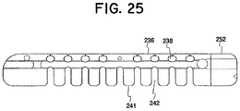
- FIG. 25is a perspective view of an augmenting elongated member of a distraction device having first conformation of spaced-apart teeth and slots along one side and a second conformation on a second side to accommodate bending in one direction and resisting bending in an opposite direction;
- FIG. 26is a perspective view of a vertebral disc having portions broken away to show the first and second elongated members of the distraction device of FIG. 22 deployed in a vertebral disc and the augmenting elongated member in a delivery cannula;
- FIG. 27is a perspective view of a vertebral disc having portions broken away to show the use of a cannula to deploy the augmenting elongated member in a vertebral disc between the first and second elongated members to augment the support structure of the device;
- FIG. 28is a perspective view of a vertebral disc between two vertebra having portions broken away to show an augmenting elongated member fully deployed between the first and second elongated members in a vertebral disc causing the first and second elongated members to contact and distract the vertebra above and below the disc;
- FIG. 29is a side view of portions of a distraction device showing a tapered distal end of an augmenting elongated member approaching the proximal end of the first and second elongated members of the device;
- FIG. 30is a perspective view of portions showing the tapered distal end of an augmenting elongated member entering a ramped opening formed by the proximal ends of first and second elongated members;
- FIG. 31is an proximal end-view of first and second elongated members of a distraction device, showing wire lumens, tissue engaging protrusions, and elongated grooves with ramped entry as employed in FIG. 30 ;
- FIG. 32is an end-view of another embodiment of an augmenting elongated member of a distraction device with protrusions on top and bottom surfaces;
- FIG. 33is an end-view of a deployed augmenting elongated member with bulbous ends on its raised ribs interacting with the elongated grooves of the first and second elongated members as employed in FIG. 30 ;
- FIG. 34is an end-view of a deployed augmenting elongated member with a raised rib interacting with a groove in a first elongated member and a groove in the augmenting elongated member interacting with a raised rib of a second elongated member;
- FIG. 35is a perspective view of first and second elongated members of a distraction device emerging from a cannula with cutouts on the top and bottom distal end of cannula;
- FIG. 36is an end view of first and second elongated members of a distraction device when located in a cannula;
- FIG. 37is an exploded side view of a delivery device showing a thumbknob and a puller platform to control the tension on pull wires, plunger body, inner delivery cannula, and outer syringe body with main delivery cannula;
- FIG. 38is side view the assembled delivery device of FIG. 37 with the pull wire ferrule attaching a pull wire to the puller platform;
- FIG. 39is a perspective view of the pull wire system and the first and second elongated members with tension on the pull wires causing curvature of the elongated members emerging from the cannula;
- FIG. 40is a top view of the pull wire system and the first and second elongated members of FIG. 39 with tension on the pull wires causing curvature of the elongated members emerging from a cannula;
- FIG. 41is a top view of the pull wire system and the first and second elongated members of FIG. 39 with an increased tension on the pull wires causing increased curvature of the elongated members emerging from a cannula;
- FIG. 42is a perspective view of an augmenting elongated member having a recess in its proximal end which interacts with a delivery device plunger;
- FIG. 43are a perspective views of delivery device with anchor loops to attach elongated members
- FIG. 44is a perspective view of a distraction device with curvature controlled by pull wires and attached to a delivery device by anchor loops;
- FIG. 45is a top view of a distraction device deployed in a disc and located adjacent or against the annulus of a disc with a cannula delivering bone graft material.
- FIG. 46is a top view of a distraction device deployed in a disc against the annulus of a disc with bone graft material filling much of the disc space including an access opening or aperture in the annulus of the disc;
- FIG. 47is a perspective view of a guide wire delivery system with first second and augmenting elongated members loaded on the guide wire in a cannula;
- FIG. 48is a perspective view of the distraction device of FIG. 47 with the augmenting elongated member deployed using a guide wire between the first and second elongated members, for clarity the distraction device is shown as straight, although it is preferably in a curved configuration in situ;
- FIG. 49is a longitudinal cross-section of a distraction device with protrusions or threads on the augmenting elongated member interacting with protrusions on the bottom surface of the first elongated member and the top surface of a second elongated member;
- FIGS. 50, 51, 52 and 53are end views of examples of the proximal ends of the augmenting elongated members configured to interact with torque delivery devices;
- FIG. 54is a top view of a segmented augmenting member loaded on a delivery wire
- FIGS. 55-60are views of examples of alternative segments of segmented augmenting members, FIGS. 55, 56, 58, 59 and 60 are top views of segments and FIG. 57 is a perspective view of a segment;
- FIG. 61is a perspective view of a distraction device with radiopaque markers in the augmenting, first and second elongated members;
- FIG. 62is a perspective view of an augmenting elongated member with a pin extending above the top and bottom surfaces thereof to provide a protrusion useful as an interlocking feature to interlock with the first and/or second elongated members;
- FIG. 63is a perspective view of an elongated member with a recess extending that acts as an interlocking feature to receive the pin of the augmenting elongated member of FIG. 62 ;
- FIGS. 64 and 65are perspective views of examples of pin-type interlocking features
- FIG. 66is a cross sectional view of a proximal end of distraction device with the interlocking features of the augmenting, first and second elongated members unengaged;
- FIG. 67is a cross sectional view of a proximal end of distraction device with the interlocking feature of the augmenting, first and second elongated members engaged;
- FIG. 68is a side view of an elongated augmented member with recesses to provide interlocking features
- FIG. 69is side view of a distraction device having spaced apart teeth or spreading members on a first lateral side with the augmenting elongated member in a first position between the first and second elongated members;
- FIG. 70is a side view of the other side of the distraction device of FIG. 69 lacking spaced apart teeth, and with the augmenting elongated member in a first position between the first and second elongated members;
- FIG. 71is a side view of the distraction device of FIG. 69 with the augmenting elongated member in a second position between the first and second elongated members spreading the first and second members apart to increase their dimensional aspect;
- FIG. 72is a perspective view of distraction device having spaced apart teeth or spreading members on a first lateral side with the augmenting elongated member in a first position between the first and second elongated members;
- FIG. 73is a perspective view of the distraction device shown in FIG. 72 with the augmenting elongated member in a second position between the first and second elongated members spreading the first and second members apart to increase their dimensional aspect;
- FIG. 74is a perspective view of the augmenting elongated member of the distraction device shown in FIG. 72 ;
- FIG. 75perspective view of the distraction device shown FIG. 72 in a curved configuration as it may be configured in situ, with the augmenting elongated member in a first position between the first and second elongated members, the device having a dimensional aspect (e.g., the distance between the upper and lower surfaces of the device) that extends in a direction between two facing tissue layers (not shown) when in situ;
- a dimensional aspecte.g., the distance between the upper and lower surfaces of the device
- FIG. 76perspective view of the distraction device shown FIG. 72 in a curved configuration as it may be configured in situ with the augmenting elongated member in a second position between the first and second elongated members spreading the first and second members apart and increasing the dimensional aspect of the structure to result in distraction of tissue layers in situ;
- FIG. 77is a perspective view of a distraction device of the present invention shown in a first configuration.
- FIG. 78is a perspective view of a distraction device of FIG. 77 shown in an augmented configuration.
- the devices and methods of the present inventionprovide multiple features of distraction devices, distraction device support structures and deployment systems that can be used to actively separate tissue layers by engaging them and forcing them apart, or to support the separation of tissue layers separated by the distraction device itself or by other devices or processes or a combination of these.
- the terms “distraction device” and “distraction device support structure”are intended to have a general meaning and is not limited to devices that only actively separate tissue layers, only support tissue layers or only both actively separate and support tissue layers.
- the distraction device and support structurein general can be used to actively separate layers of tissue and then be removed after such separation, or the distraction device and the support structure could be used to support layers of tissue that have been previously separated by a different device.
- the distraction device and support structurecan be used to actively separate the layers of tissue and remain in place to support the layers of tissue in order to maintain such separation.
- “distraction device” and “distraction device support structure”encompasses any and all of these.
- first and second members or devicesare for convenience in the written description. They may be combined to provide a single distraction assembly or structure of selected distraction height, and the assembly is not limited to only two “devices” or to only three “sleeves” or “members.” In keeping with the broader aspects of the present invention the specific number of “devices” or “sleeves” or “members” can be varied according to the intended usage or design considerations.
- FIG. 1illustrates one embodiment of a distraction device support structure, generally designated as 100 , defined by a first elongated member 102 .
- the elongated member 102is preferably comprised of elongated elements, such as a thread or ribbon, made of biocompatible materials that are suitable for long term implantation into human tissue where treatment is needed.
- the biocompatible materialsmay be calcium phosphate, tricalcium phosphate, hydroxyapatite, polyetheretherketones (PEEK), nylon, Nitinol (NiTi) or any other suitable biocompatible material.
- the first elongated member 102preferably has a generally linear configuration for insertion into tissue or between tissue layers.
- the first elongated member 102changes, preferably by flexing or bending, to a generally less linear configuration to define a distraction device support structure.
- the first elongated member 102can be bent or configured to form or define the multi-tiered arrangement, scaffolding or platform of the coil or spring-like distraction device support structure 100 having a vertical extent (e.g., the distance between the uppermost and lowermost surfaces of the structure).
- the distraction device support structure 100can serve to actively separate or support (or both) opposed tissue layers.
- the first distraction device or member, hereafter first elongated member, 102preferably includes features that add flexibility to the elongated member to assist in bending or changing the configuration of the elongated member from a generally linear configuration to a less linear configuration and vice versa.
- the first elongated member 102may include teeth 104 and slots 106 that aid in relieving stress and add flexibility to the elongated member.
- the first elongated member 102can be configured into a helical configuration with preferably a tight pitch that has an essentially cylindrical configuration. As shown, each turn or winding 108 is wound on top of or below the previous winding 108 a to form a plurality of stacked windings or tiers with lithe or no spacing between each winding or tier.
- the first elongated member 102can be comprised of a shape memory material that naturally has the configuration of the distraction device support structure 100 .
- the elongated member 102is inserted between the tissue layers in a generally linear configuration, typically through a cannula. Because of its shape memory properties, the elongated member 102 transforms from its generally linear configuration to its natural coil-like configuration to define the distraction device support structure 100 upon insertion between tissue layers.
- the first elongated member 102is made from a material that does not have shape memory properties or has very weak shape memory properties and a guide member such as a guide wire having a pre-selected shape is employed to deploy the first elongated member 102 between tissue layers and to configure the first elongated member into the distraction device support structure 100 .
- a guide membersuch as a guide wire having a pre-selected shape is employed to deploy the first elongated member 102 between tissue layers and to configure the first elongated member into the distraction device support structure 100 .
- the first elongated membercan include an aperture, such as aperture 110 , shown in FIG. 1 , extending along with the first elongated member for passage of a guide member therethrough.
- the guide memberis inserted between tissue layers and formed into a pre-selected shape.
- the first elongated memberis advanced along the pre-shaped guide member to form the distraction device support structure.
- the distraction device support structure 100includes or defines an innerspace or resident volume 112 .
- resident volumerefers generally to a structural characteristic of the support structure.
- the resident volumeis a volume that is generally defined by the distraction device support structure.
- the resident volumeis not necessarily a volume completely enclosed by the distraction device support structure and can be any volume generally defined by the elongated member(s). This term does not necessarily mean that the resident volume is an open or void volume or cavity and does not preclude a situation in which the resident volume is, at some point in time, filled with another material, such as bone filler, cement, bone graft material, therapeutic drugs or the like.
- the resident volumedoes not preclude the resident volume from containing undisturbed human tissue that is located or remains within the resident volume during or after deployment of the elongated member(s), as will be explained in more detail below.
- the resident volume of the distraction device support structuremay be hollow or void of tissue after separation.
- the resident volumewill contain undisturbed bone tissue and no void or cavity is formed by the elongated member(s).
- the elongated member 102may be used alone or in conjunction with an augmenting elongated distraction member device, such as spacer 114 , that operatively cooperates with the first elongated member 102 in order to augment or increase the vertical extent of the distraction device support structure 100 , as illustrated in FIG. 2 .
- the elongated distraction or augmenting member 114hereafter the augmenting elongated member is generally similar to the first elongated member 102 and is also preferably comprised of a generally elongated member made from or coated with biocompatible materials. In the embodiment illustrated in FIG.
- the augmenting elongated member 114operatively cooperates with the first elongated member 102 so that the windings 116 of the augmenting elongated member 114 are inserted between the windings 108 of the first elongated member 102 to increase the height of or otherwise augment vertical dimensional extent of the distraction device support structure 100 to engage and distract the facing tissue layers of the disc or vertebra.
- the first and augmenting elongated members 102 , 114have corresponding contoured surfaces that mechanically or frictionally cooperate or mate to assist in maintaining the positions of the first and augmenting elongated members relative to each other and to increase the stability of the support structure 100 .
- the first elongated member 102may have a generally cross-like cross-sectional shape that includes a top surface 118 and a bottom surface 120 .
- the top surface 118includes a protrusion 122 substantially extending along the center of the top of the first elongated member 102
- the bottom surface 120includes a protrusion 124 substantially extending along the center of the bottom of the first elongated member 102
- the augmenting elongated member 114also includes a top contoured surface 126 and a bottom contoured surface 128 .
- the top surface 126 of the augmenting elongated member 114includes an indent or groove 130 that is configured to mate with the protrusion 124 of the bottom surface 120 of the first elongated member 102 .
- the bottom surface 128 of the augmenting elongated member 114includes an indent or a groove 132 that is configured to mate with the protrusion 122 of the top surface 118 of the first elongated member 102 .
- the mating between the protrusions 122 , 124 and groves 130 , 132also can function as a guide track that guides the augmenting elongated member 114 between the windings 108 of the first elongated member 102 as the augmenting elongated member is advanced between the windings 108 of the first elongated member.
- the first and augmenting elongated members 102 , 114could have additional mating surfaces extending from either side of the first and augmenting elongated member, which mate to provide added stability to the support structure 100 .
- FIG. 3 through FIG. 8illustrates the deployment of the first and augmenting elongated members 102 , 114 into a vertebral body 134 .
- the methods described herein of deploying the first and augmenting elongated members into a vertebral bodyare for illustrative purposes and that the same or similar methods can be use to deploy the elongated members in other locations of the body, such as in an intervertebral disc or between other bone, skin or soft tissue.
- an access port 136is made in the vertebral body 134 using instruments and endoscopic procedures generally know to those skilled in the art or described in the above referenced co-owned patent applications.
- a cannula 138is then employed to advance a guide member 140 , such as the illustrated guide wire, through the access port 136 and into the vertebral body 134 .
- the guide member 140is preferably comprised of a shape memory material, such as Nitinol or other suitable shape memory material, such as a shape memory polymer, that has a natural or pre-set shape, for example, the illustrated coiled configuration.
- the cannulaconstrains the guide member into a pre-deployed configuration, such as the illustrated generally elongated linear configuration, allowing an easy and minimally invasive deployment of the guide member into the treatment site. Because of the shape memory properties, the guide member 140 will return to its natural coil-shape or deployed configuration once the constraint is removed, i.e., as the guide member exits the distal end portion 142 of the cannula 138 and enters the vertebral body 134 .
- the guide member 140can be advanced through the cannula 138 manually or with the aid of an advancing mechanism, such as the advancing mechanisms described in the above referenced co-owned applications.
- the guide member 140is advanced and deployed into cancellous bone of the vertebral body 134 until the distal end portion 143 of the guide member 140 reaches the desired height or has the desired number of loops or windings 144 .
- the guide member 140itself may function as a distraction device that contacts and separates the endplates of a damaged vertebra or disc.
- the first elongated member 102is inserted over the proximal end portion 145 of the guide member 140 , and a pusher member (not shown) is placed over the guide member behind or proximal the elongated member.
- the pusher memberis employed to contact and advance the first elongated member 102 forward or distally over the guide member 140 and out of the distal end portion 142 of the cannula 138 .
- the guide memberguides the elongated member out of the distal end portion 142 of the cannula 138 and into vertebral body 134 .
- the first elongated member 102follows along the coiled shaped distal end portion 143 of the guide member 140 and winds into a coil shaped distraction device support structure 100 ( FIG. 5 ).
- the teeth 104 and slots 106 of the first elongated member 102enhance the flexibility of the device and assists in its ability to follow the contour of the guide member.
- the distal end portion of the guide memberwill define the shape of the first elongated member in situ, for instance in a vertebral body.
- the support structureincreases in height.
- the distraction device support structure formed by the first elongated membermay or may not function to distract tissue, depending on the desired application.
- the support structure formed by the first elongated memberhas a dimensional extent, a height in this example, that extends in a direction between the tissue layers (the endplates of a single vertebra or opposed endplates of adjacent vertebra) to be distracted. In the case of the spine, the direction would be generally vertical when the patent is standing.
- the first elongated member 102is advanced over the guide member 140 until the proximal end portion 148 of the first member 102 exits the distal end portion 142 of the cannula 138 as illustrated in FIG. 6 . While the guide member 140 retains the proximal end portion 148 of the first elongated member 102 in alignment with the distal end portion 142 of the cannula 138 , the augmenting elongated member 114 is advanced through the cannula 138 and positioned so that the contoured surfaces of the augmenting elongated member 114 align and mate with contoured surfaces of the first elongated member 102 , as discussed above.
- the proximal end portion of the first elongated membercan reside in the distal end portion of the cannula as the augmenting elongated member is deployed to augment the support structure.
- the augmenting member 114As the augmenting elongated member 114 is advanced out of the cannula 138 , the augmenting member 114 is guided by the contoured surfaces between the windings 108 of the first elongated member 102 .
- the augmenting member 114can have a tapered or otherwise configured distal end portion 150 to aid in the insertion of the augmenting elongated member between the windings 108 of the first elongated member 102 .
- the windings 116 of the augmenting elongated memberare positioned between the windings 108 of the first elongated member thereby augmenting or increasing the height of the distraction device support structure 100 , as illustrated in FIG. 7 .
- the dimensional extent (in this case, the vertical dimension or the height) of the support structure 100is increased by the height of H 1 for every full winding 116 of the augmenting elongated member 114 that is inserted between the windings 108 of the first elongated member 102 .
- the height of the support structure 100is L 1 .
- the height of the support structureis L 1 +H 1 .
- the height of the support structure 100is L 1 +H 1 +H 1 .
- the guide member 140 and the cannula 138may be removed from the vertebral body 134 and the distraction device support structure 100 distracts the superior and inferior endplates of the vertebral body, as illustrated in FIG. 8 .
- bone fillersuch as bone cement, bone graft, allograft, autograft, or the like, can be inserted in the resident volume 112 and/or around the support structure using instruments and techniques generally known to those skilled in the art or generally disclosed in the above referenced co-owned patent applications.
- one advantage of a two elongated member systemis a potential reduction in the disturbance of tissue as the support structure is formed within the treatment area.
- the first elongated memberrequires less windings because the augmenting elongated member augments the height of the support structure. Because the augmenting elongated member increases the height of the support structure, the height of the support structure increases without any further rotation of the first elongated member. Less rotation of the first elongated member potentially results in a reduction in the disturbance of the tissue located in the treatment site.
- the use of a plurality of elongated membersallows the support structure to be created through a single, relatively small aperture that is significantly smaller than the structure created within the vertebra or disc.
- the resident volumealso allows for the formation of a column of bone tissue/bone cement amalgam that provides further support with a vertebra.
- the two elongated member systemcan have various alternative embodiments and features without departing form the invention.
- the mating surfaces of the first and augmenting elongating memberscould have different configurations.
- the first elongated member 152includes a top surface 154 and a bottom surface 156 .
- the top surface 154includes a convex projection 158 extending along the top of the first elongated member 152
- the bottom surface 156has a rounded or hemispherical cross-sectional shape.
- the augmenting elongated member 160includes a top surface 162 having the shape of a rounded groove extending along the top of the augmenting elongated member.
- the top surface 162 of the augmenting elongated member 160is configured to mate with the bottom surface 156 of the first elongated member 152 .
- the bottom surface 164 of the augmenting elongated member 160also includes a rounded groove 166 extending along the augmenting elongated member.
- the rounded groove 166 of the augmenting elongated member 160is configured to mate with the convex projection 158 extending from the top surface 154 of the first elongated member 152 .
- the mating of the contoured surfacescan function as a guide that guides the augmenting elongated member 160 between the windings 168 of the first elongated member 152 and can increase stability of the support structure 151 . Because of the curvature of the outer surfaces of the devices, as illustrated in FIG. 13 , the first and augmenting elongated members also can be mated and advanced through the same rounded cannula simultaneously, if desired.
- the contours of the top surface 170 and the bottom surface 174 of the first elongated member 172can be generally V-shaped or chevron shaped.
- the contour of the top surface 176 and the bottom surface 180 of the augmenting elongated member 178also can be generally V-shaped or Chevron shaped.
- the top surface 170 of the first elongated member 172mates with the bottom surface 180 of the augmenting elongated member 178
- the bottom surface 174 of the first elongated member 172mates with the top surface 176 of the augmenting elongated member 178 so that the windings 184 of the augmenting elongated member 178 nest within the windings 182 of the first distractions device 172 .
- the top surface 176 of the augmenting elongated member 178can include a rounded projection 186 that mates with a corresponding groove 188 located in the bottom surface 174 of the first elongated member 172 as best shown in FIG. 15 .
- the engagement of the projection 186 and the groove 188can aid in guiding the augmenting elongated member 178 between the windings 182 of the first elongated member 172 .
- the elongated memberincludes stress relief region 190 of any suitable shape, such as a region, void volume, region of more flexible material or a lacking material.
- the stress relief region 190allow the elongated member to bow radially outwardly when axial pressure is placed on the support structure.
- Such stress relief regionsincrease the compressibility and the elasticity of the support structure.
- These regionscan be of any desired configuration and are preferably elongated regions of substantially the same longitudinal extent as the elongated member itself.
- FIGS. 14 and 15illustrate an embodiment of a elongated member having stress relief regions 190 .
- the stress relief regiontranslates the force to the sidewalls 195 and 197 which bow outwardly.
- Such translation of stresscan aid flexibility to the distraction device support structure and assist the maintaining the general shape of the distraction device support structure when such force is applied to the distraction device.
- FIGS. 16-19illustrate another embodiment of a elongated member system that includes a first elongated member 192 and a augmenting elongated member 194 that define a support structure 196 .
- the first elongated member 192comprises a generally elongated member that can be configured to form a distraction device support structure 196 having a dimensional, i.e. vertical, extent as illustrated in FIG. 20 .
- the first elongated member 192includes a top portion 198 and a bottom portion 200 connected to each other by deformable sidewalls or webs or connection members 206 spaced along each of the sidewalls.
- the first elongated member 192also may include a longitudinal passage 204 extending generally longitudinally along the first member 192 .
- connection members 206are biased to hold the upper portion 198 and lower portion 200 of the first elongated member 192 in a relatively tight or adjacent configuration of limited vertical dimensional extent.
- the first elongated member 192has a first height of A 1 ( FIG. 17 ).
- the augmenting elongated member 194is an elongated member that can be inserted into and through a longitudinal passage 204 ( FIG. 17 ) extending along the first elongated member 192 .
- the height B of the augmenting elongated member 194can be generally larger than that of the passage 204 of the first elongated member 192 .
- the distal end portion 208 of the augmenting elongated member 194can be tapered to a size smaller than the passage 204 or otherwise shaped to assist in the initial insertion of the augmenting elongated member 194 into the passageway 204 of the first elongated member 192 .
- the augmenting elongated member 194has a height of B that is greater than the height of the passage 204 of the first elongated member 192 , when the second elongated member 194 is inserted into the passage 204 of the first elongated member 192 , the augmenting elongated member 194 contacts and forces the upper and lower portions 198 , 200 of the first elongated member 192 apart, and the deformable sidewalls or connection members 206 deform or stretch, to accommodate the separation of the upper and lower portions 198 , 200 .
- the first and second elongated membershave a combined vertical dimensional extent or height of A 2 ( FIG. 19 ), which is larger than the height of A 1 .
- the deformable sidewalls or connection members 206retain the upper and lower portions 198 , 200 of the first elongated member 192 in a tight or adjacent configuration prior to insertion of the second elongated member 194 , and are sufficiently elastic or flexible to allow the upper and lower portions 198 , 200 of the first elongated member 192 to separate into a spaced apart configuration upon insertion of the augmenting elongated member 194 .
- augmenting elongated member 194should be sufficiently rigid to keep the upper and lower portions 198 , 200 of the first elongated member 192 in a spaced apart relation. Yet, the augmenting elongated member 194 should also have sufficient lateral flexibility to allow it to transverse through the passage 204 of the first elongated member 192 , which is curved when in situ as shown in FIG. 16 . In other words, augmenting elongated member should be relatively rigid or nondeformable in a first direction that is generally parallel to the direction of tissue separation and flexible in a plane generally perpendicular to the direction of tissue separation.
- the augmenting elongated member 194could include barbs, tabs, or protrusions (not shown) spaced along the augmenting elongated member that function as anchors which retain the augmenting elongated member within the first elongated member.
- the barbscontact the inside of the first elongated member to prevent the augmenting elongated member from being withdrawn or retracted from the first elongated member.
- the barbs or tabsare preferably angled or otherwise configured to allow the augmenting elongated member to be inserted into the first elongated member and to prevent the retraction or withdrawal of the augmenting elongated member from the first elongated member.
- FIGS. 7, 8, 20 and 21illustrate methods of deploying the two elongated member system of FIG. 16 within in a vertebral disc. It will be understood that the methods disclosed herein are for illustrative purposes only and that the same or similar methods could be used to deploy the elongated members in vertebra as shown in FIGS. 3-6 or other parts of the body.
- a guide member 210(not shown) is deployed into a vertebral body 212 using similar techniques as described above in regard to FIG. 3 with respect to member 143 .
- the guide member 210is inserted through an off set lumen 211 ( FIGS. 16 and 17 ) of the first elongated member 192 , and the first elongated member with the upper and lower portions 198 , 200 in the tight adjacent configuration is advanced along the guide member 210 through the cannula 214 and into the vertebral body 212 .
- the first elongated member 192As the first elongated member 192 is advanced along the distal end portion of the guide member 210 , the first elongated member 192 take the shape of the distal end portion of the guide member and winds upon itself to form the distraction device support structure 196 having an initial vertical dimensional extent in situ.
- the augmenting elongated member 194is inserted through the cannula 214 and into the passage 204 of the first elongated member 192 to augment the support structure 196 .
- the deformable sidewalls 202stretch or deform and the upper and lower portions 198 , 200 move from their tight configuration to a spaced apart configuration, which increases the dimensional extent or height of the structure formed by first elongated member 192 .
- the increase in height of the first elongated member 192in turn increases the height of the support structure 196 , resulting in distraction of the endplates or further distraction of the endplates of the vertebra on either side of the disc space.
- the cannula 214 and guide member 210are preferably removed, leaving the support structure 196 implanted within the vertebral body 212 .
- FIG. 22One embodiment of a distraction device support structure defined by a distraction device 239 is shown in FIG. 22 .
- the distraction device shown in FIG. 22is comprised by a first elongated member 252 , a second elongated member 253 and an augmenting elongated member 255 that cooperatively interacts with the first and second elongated members to increase a dimensional aspect of the distraction device support structure.
- the distraction devicemay comprise two or more separate members or sleeves
- the distraction deviceis preferably comprised of an elongated members, such as a thread or ribbon, made of biocompatible materials (including metals and polymers) that are suitable for long term implantation into human tissue where treatment is needed.
- the biocompatible materialsmay, for example, be calcium phosphate, tricalcium phosphate, hydroxyapatite, polyetheretherketones (PEEK), nylon, Nitinol (NiTi) or any other suitable biocompatible material.
- Biocompatible materialmay also include PEEK with carbon fibers, polyethylenes of low, medium and or high densities, as well as nylons and blends of materials that contain nylons.
- the elongated members which form the distraction device support structurepreferably have a generally linear configuration for insertion into tissue or between tissue layers.
- the elongated memberschange configuration, preferably by flexing or bending, to a generally less linear configuration to define a distraction device support structure.
- the elongated members 239can be bent or otherwise configured to form or define a scaffolding, platform or structure of a semicircular shape.
- the distraction device 239forms support structure having an annulus-like shape.
- the distraction device support structurecan serve to actively separate and/or support (or both) opposed tissue layers such as end plates of a vertebrae or opposed end plates of adjacent vertebrae.
- the elongated members of the distraction devicemay include features that add flexibility to the elongated member to assist in bending or changing the configuration of the elongated member from a generally linear configuration to a less linear configuration and vice versa.
- the elongated member 252 seen in FIG. 24Amay include lateral teeth 241 and intermediate slots or indents 242 that aid in relieving stress and add flexibility to the elongated member.
- the slotsmay also provide gaps for the introduction of bone graft materials, cements, or pharmaceutical compounds to the spinal tissues.
- the elongated membersmay also be designed such that the adjacent teeth or other structures on either side of the slot prevent further bending beyond a finite desired angle.
- opposed sides of an elongated member 252displays two different types of structures.
- T-shaped members 237 on one side of the memberhave longitudinal extensions on their outmost edge such that adjacent members almost touch each other, leaving a relatively narrow opening at the mouth the indent or aperture 238 between adjacent members.
- the longitudinal extensions on adjacent memberscome in contact and provide resistance to further bending acting as a stop to limit further curvature.
- the teeth or members 241 on the opposite side of the elongated memberlack such longitudinal projections and therefore the elongated member can be bent to a much greater degree in this direction before these teeth 241 come in contact with adjacent teeth to limit further curvature. Also, it should be noted that by providing the T-shaped members 237 and intermediate indentations or gaps 238 , increased flexibility is provided that allows the elongated member to bend toward the opposite side.
- Additional featuresmay be added to enhance or limit the flexibility of the elongated members of the distraction devices, including grooves, slots, channels, and pockets and teeth or other extensions or members of various shapes.
- the slots, grooves, channels, and pocketsmay be placed, for example, in a linear pattern or spirally around the body of the elongated member. Through holes or apertures may also assist in providing flexibility as well as serve as lumens for guide wires, or pull wires, discussed later.
- the placement of a greater number of these features in one region of an elongated membercan make that region more or less flexible than other regions of the device with fewer or different flexibility enhancing or limiting features.
- the flexibility featurescan be located uniformly along a segment or the whole of the device to provide regions of uniform flexibility.
- first and second elongated membersmay also be provided by having a greater number of flexibility features on a particular side or sides of the elongated members. For instance, a series of slots on one side of a member can reduce the amount of force required to deflect that the elongated member toward or away from the slotted side. Flexibility of the elongated member may also be achieved or varied by fabricating the device from a combination of materials with different degrees of flexibility. For instance, by located more rigid material on one side of a member, the member may be easier to bend or deflect toward that side.
- the more rigid materialmay tend to retain the desired configuration to a greater degree than the other material and form the desired configuration which introduced into the disc or vertebra.
- the elongated membercan have alternating or different sections along its length that are made of different materials having different rigidity.
- the elongated membersare characterized by an ability to recover from temporary deformation.
- the elongated member(s)may be pre-set or pre-formed into a desired in situ shape and then temporarily reshaped, such as by straightening, for insertion.
- a pre-shaped elongated membermay tend to recover its shape more quickly or completely in body-temperature spinal tissue after being in a less curved conformation during shipping and storage inside a deployment cannula.
- the elongated membersmay not recover their original shape after extended deformation in the cannula, and an external force may be used to shape the elongated member after it is inserted in the cannula.
- an external forcemay be applied, for example, by a guide member such as guide member 140 previously discussed (see FIGS. 3 and 4 ) or pull wires to be discussed in more detail later.
- the deformation of elongated membersare constrained in a first axis and allowed in a plane at an angle to the first axis to allow deflection in a different plane.
- a semi-circular distraction device support structureis shown in a vertebral disc.
- the support structureis formed by three elongated members, 252 , 253 , and 255 and is relatively rigid in the direction (e.g., a vertical direction when standing) extending between two tissues layers, i.e. the adjacent vertebra.
- the distraction deviceis resistant to deflection in a direction parallel to the longitudinal axis of the spine due to the relative solid, continuous structure of the elongated members along this axis.
- the elongated members 252 , 253 , 255forming the distraction device support structure shown in FIG. 28 . Consequently, due to the structure of the elongated members 252 , 253 , 255 forming the distraction device support structure shown in FIG. 28 , no deflection or only limited deflection is allowed in the direction of distraction. In contrast, the elongated members are relatively more flexible in the plane perpendicular to the direction of distraction to allow the elongated members to be shaped as desired, such as curved or deflected to conform the shape of the space in which they are implanted.
- the distraction device support structuredoes not substantially compress under vertical forces the human spine normally endures, such as but not limited to up to about 1000 N.
- this relative rigiditymay be provided by the elongated members having a nearly continuous or relatively solid core portion extending along the vertical extent of the structure.
- an elongated member composed of PEEK with a center core or wall 236 , between indents, that is from about 0.5 mm to about 1.7 mm widewill not substantially compress under normal physiological forces, and may even support a vertical force greater than about 3000 N.
- the width of the corecan be of any suitable size, such as from about 0.7 mm to about 1.5 mm, or from about 0.9 to about 1.3 mm, or from about 1 mm to about 1.2 mm and other ranges.
- the elongated member as discussed previouslycan have teeth on both sides, with a center solid core or, as shown in other embodiments, elongated members may have teeth on only one side with a back or side wall providing a core support for vertical forces.
- the distraction devices of the present inventionmay assume a variety of shapes with a radius of curvature ranging from infinite, i.e. a straight line, to about 3 mm or less. Curved distraction devices may span arcs from about 30° to more than 360°.
- the depth of indents 242may vary, depending on the width 235 ( FIG. 24A ) of the elongated member at the teeth adjacent to the indent and the width of the core support between teeth 236 .
- the width of elongated members at their widest pointcan be, as an example only, from about 3 mm to about 9 mm. More particularly for spinal application width may preferably but not necessarily, be from about 5 mm to about 7 mm wide.
- a width of 9 mm, and a core support of 1.5 mmthen the depth of indents on each side would be about 3.75 mm.
- a width of 9 mm at the teeth and a core between teeth of 1.5 mmthen the sum of the depth of opposed indents would be 7.5 mm.
- the width 234 of indents 242may also affect the flexibility or degree of flexing permitted.
- One example of the width to provide sufficient flexibility on the concave side of curved elongated membercan be from about 0.5 mm to about 1.5 mm. More particularly width can be from about 0.7 mm to about 1.3 mm, or from about 0.9 mm to about 1.1 mm. This may be viewed as a desired or preferable minimum width, but other widths may also work depending on the procedure and size of the elongated member and other features of such member.
- the height of the distraction device support structure H d in FIG. 33preferably should be sufficient to restore the disc to its normal height or thereabout, which will depend on the size of the patient and the discs location in the spinal column.
- the height the support structurecan be, for example, from about 5 mm to about 15 mm. More particularly the height can be from about 7.5 mm to about 13.5 mm, or about 9 mm to about 12 mm and ranges therein.
- the disc size and consequently the height of the support structurecan be, for example, from about 5 mm to about 7 mm.
- the disc height and consequently the height of the support structurecan be, for example, from about 9 mm to about 15 mm or greater potentially.
- the shape of the disclosed distraction device support structuresmay be assisted, controlled and/or adjusted as the elongated members are being deployed between the tissue to be distracted.
- the forces required to control the shape of the disclosed elongated membersare compatible with typical hand-held delivery systems and tools.
- the shape of the elongated membermay be controlled with pull wire systems deployed either inside the elongated member(s) and/or outside the elongated member(s).
- the shape of the elongated members of the present inventionmay also be controlled with guide-wires such as pre-shaped nitinol wires, such as guidewire 140 described earlier.
- the disclosed elongated membersmay also be shaped with flexible or curved screws inserted into the elongated members.
- the disclosed elongated membersmay also be shaped with flexible or curved rods in combination with a geometric pathway.
- the elongated members disclosed hereinmay also be pre-shaped such that the device returns to a shape that is identical or similar to its original shape after being straightened or curved to allow delivery to spinal or other tissues through a cannula.
- the shape of the elongated members disclosed in this inventionmay alter in response to a change in temperature or electrical current, such that insertion into the tissue, e.g. spinal tissue, will result in the device assuming a more desired conformation.
- the various mechanisms disclosed herein for control of the shape or deformation of elongated members of the present inventionmay be used separately or in combination such that more than one control mechanism may be used to determine the shape and/or location of distraction device support structure in situ.
- the elongated members of the present inventionmay be manufactured using a number of techniques including machining or milling techniques. Milling can include cutting elongated members from solid blocks or rods of PEEK or other suitable material. Elongated members may also be manufactured using molding techniques. Molding techniques include co-molding various materials together to form a elongated member, as well as molding a second material over a first material. Elongated members may also be manufactured by injection molding or extrusion processes. In addition the elongated members of the present invention may be manufactured with Electrical Discharge machining process and by rapid prototyping methods including fused deposition modeling (FDM) and stereo lithography (SLA) techniques]
- FDMfused deposition modeling
- SLAstereo lithography
- Elongated members manufactured from polymeric materials such as PEEKmay be pre-shaped by placing the elongated member in a metal fixture or jig having a desired shape, such as a semicircular shape, and then heating the elongated member to relieve the bending stress. For instance the elongated member can be treated for about 5 minutes at about 160° C.
- the pre-shaping processbiases the elongated member toward a desired shape yet still allows the elongated member to be deformed either in the cannula or in situ after the elongated member is inserted into a tissue.
- the elongated membersdo not shape memory material properties. Consequently, in some embodiments, particularly when PEEK is used, the elongated member does not return to its original shape without the additional application of an external force to shape the member.
- the shape, distribution and size of the teeth 241 and slots 242 on the sides of the elongated members 239can be configured to assist in forming various curved or bent shapes.
- the distraction devicecan be configured in closed structures such as oval-, disc-, rounded corner quadrilateral-, and other rounded corner polygon-like distraction device support structures.
- the distraction devicecan be bent or configured in open structures such as semi-circular shapes in which the neither the proximal 243 nor the distal 244 end of the device touch another end or other surface of the device.
- the distal ends of the elongated memberscan have chamfer and wedge features to ease the passage of the elongated member through tissue such as bone or disc material.
- tissuesuch as bone or disc material.
- a chamfer feature 232is visible on the upper surface of the proximal end of first elongated element.
- the first elongated membercan be configured with surfaces 245 , 246 that mate or otherwise engage to assist in maintaining the closed structure such as the annulus shape illustrated in FIG. 23 .
- FIG. 24Billustrates an example of such mating surfaces, with a protrusion on one end 245 of the elongated member that fits into a notch like recess 246 on the elongated member.
- the notch recess 246is an indentation configured to securely receive the protrusion and is generally shaped to match the shape of the protrusion 245 .
- a rectangular protrusionmay be matched with a generally rectangular indentation, or a ball shaped protrusion may be match with a semicircular indentation.
- a particular surface 247 of the indentationmay be tapered to assist the entry of the protrusion into the indentation.
- the distraction device 239may itself be composed of two or more elongated members, hereafter exemplarily referred to a first member and a second member.
- the first membermay also be referred to as a top member or sleeve 252 while the second member may also be referred to as a bottom member or sleeve 253 as shown in FIGS. 29, 30 and 31 .
- the protrusions and indentations of the mating surfaces of the first and second elongated membersmirror each other.
- a first distraction device 240 comprised of a first elongated member 252 and second elongated member 253can be comprised of a shape memory material that naturally has the configuration of the distraction device support structure in situ.
- the elongated membersare forced into a linear configuration, such as in a cannula 284 , and inserted between the tissue layers in a generally linear configuration, typically through the cannula 284 .
- the elongated memberstransforms from a generally linear configuration to their natural semi-circular, or annular or coil-like configuration to define the distraction device support structure upon insertion between tissue layers.
- the shape memory material used in elongated membersoptionally includes materials that are shaped into a particular configuration using an annealing process such disclosed in the co-owned patent applications referenced herein.
- the distraction device support structure 240may include or define an innerspace or resident volume.
- resident volumerefers generally to a structural characteristic of the support structure.
- the resident volumeis a volume that is generally defined by the distraction device support structure.
- the resident volumeis not necessarily a volume completely enclosed by the distraction device support structure and can be any volume generally defined by the distraction device. This term does not necessarily mean that the resident volume is an open or void volume or cavity and does not preclude a situation in which the resident volume is, at some point in time, filled with another material, such as bone graft, cement, therapeutic drugs or the like.
- the resident volume of the distraction device support structuremay be hollow or void of tissue after separation.
- the resident volumewill contain undisturbed bone tissue, and no void or cavity is formed by the distraction device.
- the resident volumemay contain undisturbed disc tissue such as a portion of the nucleus pulposus or bone graft material placed before or after installation.
- the first distraction devicecomposed of first and second elongated members, may be used alone or in conjunction with a second distraction device 255 or spacer hereafter exemplarily referred to as an augmenting elongated member that operatively cooperates with the first 252 and second 253 elongated members of the first distraction device in order to augment the distraction device support structure.
- the augmenting elongated member 255preferably comprises a generally elongated member made from biocompatible materials and as shown in FIGS. 30 and 33 may have any of various additional features or aspects such as teeth 241 and slots 242 . In the embodiment illustrated in FIGS.
- the augmenting elongated memberoperatively cooperates with the first and second elongated members such that the augmenting member 255 is inserted and slides between the first elongated member 252 and the second elongated member 253 to increase the height of or otherwise augment the distraction device support structure.
- the degree of height increase of or other augmentation of the distraction device support structureis dependent upon the height (or width) of the augmenting elongated member. For instance, as illustrated in FIGS. 33 and 34 thicker augmenting elongated member 255 will cause a greater increase the height of the distraction device support structure than a thinner augmenting elongated member.
- the height of the distraction deviceis fixed and is not adjustable or variable.
- the augmenting memberis preferably fixed in position between the first and second elongated members and not removal.
- the thickness of the augmenting elongated member 255can be different along its length to cause different amounts of additional distraction along the length of the distraction device.
- the proximal portion of the augmenting membermay be thicker (taller) than the distal portion of the augmenting member, then the increase of the height of the proximal portion of the first device will be greater than the augmentation of height for the distal portion of the device.
- the ability to create a greater increase in height in one region of a distraction deviceallows for adjustments in the curvature of the spine of a patient. For instance, a collapsed disc in the lumbar region of the spine can result in the loss of the normal lordosis in the lumbar region of the spine.
- a augmenting elongated member 255 of variable thickness in a distraction device installed in a collapsed lumbar disccan restore the lumbar disc to the more normal morphology of a greater height on its anterior region as compared to its posterior region—in that situation, the augmenting member may have a greater height its central region between the distal and proximal ends than at either the proximal end or distal end.
- either or both of the first or second elongated membercan also be made to have different thickness at different locations, such as by altering the surfaces of the first and second elongated members to match the lordotic angle in the device final configuration. For example, if the device is to be deployed in a semi-circular configuration (see FIGS. 45-46 ) with the middle of the length of the elongated members placed at the most anterior portion of the disc space, the height of the proximal and distal ends of the first and second elongated members could be tapered gradually down to match the desired lordotic angle.
- a single or multiple thin/small profile protrusion(s) matching the normal max device profile running along the lengthcan be left on the tapered upper or lower faces of the first and second elongated members.
- These protrusionsmay act to stabilize the first and second elongated members inside the cannula during deployment, but once implanted inside the disc space, the thin/small profile protrusions would preferentially subside until the tapered outer surfaces of the first and second elongated members are supporting the lordotic face of the endplates.
- the first 240 and second 255 elongated membersmay have corresponding contoured surfaces or features that mechanically or frictionally cooperate or mate to assist in maintaining the positions of the first and second elongated members relative to each other and to increase the stability of the support structure.
- first and second distraction devicesare for convenience in the written description. They are combined to provide a single distraction assembly or structure of selected distraction height, and the assembly is not limited to only two “devices” or to only three “sleeves” or “members.” In keeping with the broader aspects of the present invention the specific number of “devices” or “sleeves” or “members” can be varied according to the intended usage or design considerations.
- the first distraction devicehas a first elongated member 252 that includes a top surface 256 and second elongated member 253 that includes a bottom surface 258 .
- the top surface of the first elongated member 256may include tissue-engaging structures, such as intermittent, spaced apart protrusions 266 including ribs, teeth or textured surface or the like and the bottom surface of the second elongated member 258 may also include similar protrusions 267 .
- an individual protrusionmay extend substantially along the top surface 256 of the first elongated member, and an individual protrusion may extend substantially along the bottom surface 258 of the second elongated member.
- an individual protrusionmay be elongated bars that extend laterally along the top surface of first elongated member and the bottom surface of the second elongated member.
- the bottom surface 257 of the first elongated member 252 240may contain a contoured surface 262 , while the top side 259 of the second elongated member 253 240 may also be contoured 263 , as shown in FIGS. 31, 32, 33, and 33 .
- the augmenting elongated 255 memberalso may include a top contoured surface 265 or and a bottom contoured surface 266 .
- the top surface 264 of the augmenting elongated membermay include a protrusion raised or rib 265 that is configured to mate with an indentation or slot 262 in the bottom of the first elongated member 252 .
- the top surface of the augmenting elongated membermay include an indentation or that is configured to mate with a protrusion or rib on the bottom surface of the first elongated member.
- the bottom surface 266 of the augmenting elongated membermay include a protrusion 267 or a groove 268 that is configured to mate with a groove 263 or a protrusion 269 included in the top surface 259 of the second elongated member of the first distraction device 240 .
- the cooperation between the protrusions and grooves in the interfacing surfaces between of the elongated membersalso can function as a guide or guide track that directs the augmenting elongated member 255 between the first 252 and second 253 elongated members.
- the entrances to grooves 262 , 263 of the first and second elongated memberscan also be ramped 274 to provide a larger opening on the proximal ends of the grooves to ease the entry of a tapered 273 distal end of augmenting 255 member between the first and second elongated members.
- the elongated membersmay have additional mating or guiding surfaces extending from either sides of elongated members which provide added stability to the resulting support structure.
- the first elongated member 252may have projections 270 along the bottom surface 257 .
- the top surface 259 of the second elongated member 253may also have projections 271 .
- the projections 270 , 271 on the bottom of the first elongated member and the top of the second elongated membermay be shaped to define internal threads or thread segments.
- the augmenting elongated member 555may also have projections 272 along its external surface that are configured as external threads.
- the protrusions 272 on the surface of the augmenting elongated membercan cooperate with the protrusions 270 , 271 on the first and second elongated members to allow threading advance of the augmenting member between the first and second members. Threading the augmenting elongated member 255 between the first 252 and second 253 elongated members can separate the first 252 and second elongated members 253 to augment the height of the distraction support structure. Using a threaded arrangement also provides a mechanical advantage that may also assist in overcoming internal friction and ease the insertion of the augmenting member between the first and second elongated members
- the distal end 273 of the augmenting elongated membermay have a smaller or tapered cross-sectional area that assists in initiating the insertion or threading of the augmenting elongated member 255 between the first and second elongated members.
- the proximal end 243 of the first and second elongated members of themay have an outwardly tapered regions 274 extending in from the proximal end 243 of the first and second elongated members along the interface of the first 252 and second 253 elongated members.
- These outwardly tapered regions on the proximal ends of the first and second elongated membersform an enlarged receiving region that may assist in aligning the elongated members and in initiating the threading of the augmenting 255 elongated member between the first 252 and second 253 elongated members.
- the proximal end 276 ( FIGS. 50-53 ) of the augmenting elongated membermay contain either a protrusion 277 or a recess 278 shaped to secure the interaction of the augmenting elongated member with a torque delivery tool.
- a wide variety of shapescan be used to facilitate the interaction of the augmenting elongated member and the torque delivery device, for example in FIGS. 50-53 Phillip's-, square-, and star-type endings are shown.
- an access portis made through the annulus of a disc using instruments and endoscopic or minimally invasive procedures generally known to those skilled in the art or described in the above referenced co-owned patent applications.
- all or a portion of nucleus pulposusis removed and the endplates of the adjacent vertebra are scraped to cause bleeding and promote the fusion of bone graft material to the vertebral endplates.
- Sizing paddles or like apparatusmay be slipped through the access port to determine the minimum disc height.
- a cannula 254is then employed to advance a guide member, such as the illustrated delivery wire 279 of FIG. 47 , through the access port and into the intervertebral disc.
- the guide member 279is preferably comprised of a shape memory material, such as Nitinol or other suitable shape memory material, such as a shape memory polymer, that has a natural or pre-set shape, for example, the illustrated annulus or semicircular configuration.
- a shape memory materialsuch as Nitinol or other suitable shape memory material, such as a shape memory polymer, that has a natural or pre-set shape, for example, the illustrated annulus or semicircular configuration.
- the guide memberwill return to its natural curved-shape or deployed configuration once the constraint is removed, i.e., as the distal end of the guide member 281 exits the distal end portion of the cannula 254 and enters the disc.
- the guide member 280can be advanced through the cannula 254 manually or with the aid of an advancing mechanism, such as the advancing mechanisms described in the above referenced co-owned applications.
- the guide member 279is advanced and deployed into the disc, typically along the inner wall of the annulus fibrous, however, depending on the nature of the repair, other paths may be selected for the guide member. Advancement of the guide member 279 is halted when the guide member forms the desired closed (e.g., rounded polygons and annular) or open structure (e.g., semicircular) structure. Depending on the desired procedure, the guide member 279 itself may function as a distraction device, separating adjacent vertebrae. As illustrated in FIG. 47 , for example, the first and second elongated members 252 and 253 are inserted over the guide member 279 . The first and second members may have facing surfaces that cooperate with the augmenting member or with each other. Referring back to FIGS.
- a slot or groove 262may be provided in the bottom of the first elongated member 252 and a slot or groove 263 the top of the second elongated member 259 , and the guide member maybe configured to fit in one or both of these grooves.
- these grooves 262 , 263may also serve as guides for the insertion of the augmenting elongated member 255 between the first and second elongated members 252 , 253 .
- separate guidewire lumens 282 and 283may be provided in the first and second elongated members, and they may be inserted by passing them over separate guidewires or members.
- a pusher memberfor example a plunger 297 can be placed over the guide member behind or proximal to the elongated members.
- the pusher memberis employed to contact and advance the first members forward or distally over the guide member and out of the distal end portion of the cannula.
- the guide memberdirects them out of the distal end portion of the cannula and into the intervertebral disc.
- the pair of first and second elongated members(sometimes referred to as the first distraction device 240 ) in FIGS. 29-41 and 47-48 follows along the distal end portion 279 of the guide member and may be shaped by the guide member to form the desired open or closed (or other) shaped distraction device support structure.
- the teeth 241 and slots 242 of the elongated membersenhance the flexibility of the device and assist in its ability to follow the contour of the guide member 279 .
- the first and second elongated members 252 , 253may be advanced over the guide member 279 until the proximal end portion 243 of the first and second elongated members exit the distal end portion of the cannula 284 .
- the augmenting elongated member 255may be advanced over the guide member and through the cannula 254 and positioned so that the distal end of the augmenting elongated member (which may be tapered or contoured) aligns and mates with proximal surfaces of the first and second elongated members 252 , 253 as discussed herein.
- first and second elongated members 252 and 253 and augmenting elongated member 255 and the cannula 254may be configured so that the first and second elongated members and augmenting elongated member can all reside in the cannula at the same time, and then all three members may be advanced through the cannula simultaneously, until the proximal end portion of the first and second elongated members reside in the distal end portion of the cannula 284 as the augmenting elongated member 255 is inserted between the first and second elongated members 252 , 253 . As illustrated in FIG.
- the distal end of cannula 284may have cutouts 285 to allow the cannula to restrain first and second elongated members in one direction, while simultaneously allowing augmentation of the height of the first device 240 (i.e., the first and second elongated members) in a second dimension when the augmenting elongated member 255 is inserted between the first and second elongated members 252 and 253 .
- the augmenting elongated member 255may be directed by a guide member 279 .
- the augmenting membermay have a lumen 286 which allows the augmenting elongated member 255 to be loaded on the same guide member 279 as the first and second elongated members 252 , 253 .
- Advancing the augmenting member along the guide member 279directs it to a location between the first and second elongated members.
- the augmenting elongated membercan have a tapered or otherwise configured distal end portion to aid in the insertion of the augmenting member between the first and second elongated member 252 , 253 .
- the augmenting elongated membermay be a comprised of a plurality of separate segments 287 instead of being a continuous member.
- the augmenting memberreadily follows and conforms to the shape of the first and second elongated members in situ.
- the segments of the augmenting elongated membermay contain top and/or bottom contoured features such as grooves or protrusions that allow the segments to interact with or cooperate with protrusions or grooves in the facing surfaces of first and second elongated members. As discussed previously herein and shown in FIG.
- an augmenting elongated member comprised of segments 287may contain a lumen 288 through each segment, which lumen is loaded over a guide member 279 to facilitate the insertion of the segments 287 of the augmenting elongated member between the first 252 and second 253 elongated members.
- the height of the segments 287 comprising the augmenting elongated membercan be different such that different regions of the resulting distraction structure provide different amounts of height augmentation. As noted above, this ability to control the height of the various regions of the support structure allows the correction of abnormal curvature of the spine for instance by selectively increasing the height on a particular side of intervertebral disc or a vertebral body.
- the facing surfaces to segmentscan be contoured to interact with the adjacent segments of the augmenting elongated member.
- the segmentsmay possess opposed concave and convex adjacent surfaces such that a proximal 290 concave surface on one segment contacts and cooperated with a convex distal 289 surface of the adjacent segment.
- a few examples of segment shapes which allow segment interactionare shown in FIGS. 55-60 .
- adjacent segmentsmay also have interlocking features.
- the resulting distraction device support structuredistracts the intervertebral disc.
- the introducing cannula and guide membersif any, may also be removed.
- bone fillersuch as bone cement, allograph, autograph or the like, can be inserted in the resident volume and/or around the support structure using instruments and techniques generally known to those skilled in the art or generally disclosed in the above referenced co-owned patent applications.
- the bone fillercan be inserted into the disc space after measuring the disc space and before the introduction of the distraction structure.
- the shape of the first and second elongated memberscan be controlled during insertion, by applying a greater force to one side of the elongated members than is applied to the other side.
- the application of unequal forcecan cause the elongated members to curve in a particular direction.
- FIGS. 39, 40, and 41show a system with a pull wire 291 that passes through both the top 252 and bottom 253 elongated members.
- the pull wires 291may pass through a wire lumen 282 , 283 of each top and bottom elongated members like those shown in FIGS. 31 and 39 or, alternatively, through a wire channel or slot that is not fully enclosed.
- Pull wire 291may be a single wire or multiple wires and may be of any flexible material that can be used exert a force along the length of the elongated members 252 , 253 , 255 and include steel, Nitinol, fiber both synthetic and natural, or the like. In the examples shown in FIGS. 39, 40, and 41 the pull wire 291 is on the left side of the elongated members 252 , 253 (as viewed from the proximal end) and an exertion of force, a pull on the wires, will cause the elongated members to curve to the left in the direction of the pull.
- Alternatively, systems in which a push, an extension force, applied through a rigid pushercould be provided to a elongated members to cause the elongated members to curve in the opposite to the direction of force application.
- a pull wire 291may only pass through one of the first 252 or second 253 elongated members to control the shape and placement of the first and second members.
- a pull wire 291 or wiresmay also be used to control the shape and placement of the augmenting member, such as member 255 in FIGS. 25-30 , by passing the wire through a lumen that extend longitudinally through the augmenting member.
- Imaging techniquesallow real-time and near real-time monitoring of the location and curvature of distraction devices during surgery and systems which apply an unequal force to the first and second elongated members 252 , 253 also allow fine control with visual confirmation of the placement and the shape of the first and second elongated members in the spinal tissue.
- pull wires 291may be removed by releasing the ends of the wire or wires and withdrawing from the elongated members.
- Various devicesmay be used to apply tension to the pull wires for shaping elongated members.
- the force exerted on pull wires 291 and similar devices for delivering a greater force to one side of elongated membersmay be controlled by a platform 294 or arrangement that is associated with an advancing mechanism 295 .
- a force delivery platformcan comprise, for example, thumbknob 293 associated with an advancing mechanism, the plunger body 295 of FIGS. 99 a and 99 b.
- the force delivery platformmay contain regions 296 designed to attach pull wires 291 .
- wire attachment regionsinclude invaginations, slots such as the ferrule nests 294 seen in FIG. 38 , as well as clamps, brackets, screws etc.
- the thumbknob 293may have threads 298 that interact with threads 299 on the puller platform 294 such that rotating the thumbknob 293 will adjust the tension of the pull wire 291 .
- the force delivery platform 292may interact with the advancement mechanism 295 , for example through a keyway 297 as shown in FIG. 38 , such that rotation of the thumbknob 293 adjusts the tension on pull wires 291 but does not cause rotation inside the advancement mechanism 295 , i.e. the plunger body of the embodiment shown in FIGS. 37 and 38 .
- the tension on the pull wires 291or other devices for delivery of a greater force to one side of elongated members may also be controlled by similar tensioning devices that are known to one of skill in the art, such as screw-drives, plungers, gear mechanisms and the like.
- the use of pull wireshas other advantages also.
- the insertion of the augmenting elongated member between the first and second elongated memberscan create a repulsive force that can push the first and second elongated members away from both the cannula of a delivery device and the augmenting member.
- the force exerted by pull memberssuch as pull wires controlling member curvature, and the force of friction between the surfaces of the first and second members and the surrounding tissues, such as the endplates of the vertebra above and below a disc, can also serve to resist this repulsive force.
- the magnitude of the resisting forcesmay make insertion of the augmenting member increasingly difficult.
- the first and second elongated membersdo not contact the vertebral plates until the augmenting member is deployed to increase the height of the support structure.
- Increasing the force on the pull wires that control the curvature of the members to overcome the repulsive forcecan, if too much force is exerted, increase the curvature of the first and second elongated member.
- Increasing the curvature of the first and second elongated memberscan hinder the ability of the augmenting elongated member to translate along the grooves and/or protrusions of the first and second members which form a guide tract for the insertion of the augmenting member.
- An excessive increase in the force on the pull wirescan also cause excessive or undesired curvature of the first and second members.
- an anchoring or tethering systemcan be used to hold the first and second elongated members aligned with the distal end of delivery cannula while the augmenting elongated member is inserted between these members.
- the tethering systemcan include an anchoring or tethering cable which attaches to the proximal end regions of the first and second elongated members and to the proximal end region of a delivery device.
- the attachmentcan be a cable or line that provides little resistance to the deployment of first and second elongated members, permitting the members to exit the distal end of cannula.
- the length and tension of the anchor cables or tethersare adjustable to provide increased tension after the first and second elongated members have exited the cannula.
- the tetherskeep the first and second elongated members in close proximity to the distal end of the cannula allowing the insertion of the augmenting elongated member between the first and second elongated member without having to increase the tension on the pull wires controlling the curvature of the members.
- the tethercan be attached to the first and second elongated member by looping the tether to form an attachment or anchor loop(s) which engage with the proximal end regions of first and second elongated members.
- the free ends of the tether linecan be attached to attachment points 323 , 324 in attachment wells 327 and 328 located in the proximal end region of the delivery device.
- the tether lines 320 , 321can pass inside the delivery device including through the delivery cannula of the delivery device.
- the attachment loopscan associate with the elongated members 252 , 253 to attach the members to the deliver device by passing through holes in the proximal end region of the elongated members or around engaging surfaces on the elongated members.
- the tether linesmay also associated with the elongated members by passing through slots, pull-wire lumens or other like features.
- the tether linesmay also associated with various protrusions, teeth, slots on the proximal end region of the elongated members.
- the first and second elongated memberscan be attached to the delivery device with a single tether line or loop or more than one tether line or loop.
- FIG. 43illustrates the use a single tether wire or line to form two attachment loops 320 , 321 by passing the wire around a tensioning pin 322 located on the proximal region of the delivery device with each end of the tether attached to separate fixing pins located in attachment wells 327 , 328 at the proximal region of the delivery device.
- the anchoring loops attaching the elongated members to the delivery devicecan be released, for instance, by accessing the wire through a channel 325 and cutting the wire.
- the fixing pinsare readily released and one end of the wire can be pulled to remove the wire from the first and/or second elongated members.
- the tension on the anchor wiremay be relaxed after the augmenting elongated member is deployed, without cutting the anchoring wire, to ease the release of an end of the wire and the removal of the wire from the elongated members.
- the amount of slack in the anchor loopsis regulated by regulating tension on the tensioning pin 322 .
- the tensioning pin 322which is located on a sliding feature 330 to which a tensioning spring 326 is attached.
- the spring 326can exert moderate tension on the sliding feature 330 to provide a limited resistance and prevent slack in the anchoring loops 321 , 320 while allowing the elongated members to move down and out of delivery cannula 320 .
- the sliding featurehits a stop, increasing the resistance on the anchoring loops 320 , 321 and retaining the elongated members in close proximity to the distal end of the delivery cannula.
- the tension on the tensioning 322 pinwhich can regulate the slack in the anchor loops, may be controlled with a spring 326 such as a constant force spring, or variable force springs, ratcheting mechanisms, winding spools, stretchable cables with a limited final length and the like.
- a spring 326such as a constant force spring, or variable force springs, ratcheting mechanisms, winding spools, stretchable cables with a limited final length and the like.
- ends of tether linescan be directly attached to the tensioning pin or multiple tensioning pins.
- tether linescan be attached directly to spool type or ratchet type systems with or without drag adjustment features.
- free ends of tether linecan be attached to a single site on the proximal end region of a delivery device, for instance the tensioning 322 pin or a fixing pin.
- the each free endmay be affixed to separate sites on the proximal end region of the delivery device.
- Tether lines, wires or cables 320may be attached to the delivery device or elongated members by releasable mechanical features such as screws, clamps, crimps and ferrules and other like means. Cables or wires may also be attached by knotting, gluing or pinching the cable to the delivery device or in some cases the elongated member.
- the anchor or tether wire or cablemay consist of materials suitable for sterilization and compatible for temporary contact with animal, including human tissue.
- Metal anchor cablesinclude stainless steel, nitinol, or other suitable metal wires.
- Nonmetal anchor cablesinclude natural fibers and polymeric fibers including polyethylene, ultra-high molecular eight polyethylene (UHMWPE), Victrex, Pet, or similar medical-grade polymers.
- the tether line wire or cablemay be wound on a spindle, with the spindle controlling the tension on the tether.
- the spindlemay also limit the total amount of line released to hold the deployed elongated members at the desired location in close proximity to the distal end 334 of the cannula.
- the tension in tether lines or cablesmay be controlled by other means such as springs, resilient means, sliding mechanisms, rotating mechanisms, moving mechanisms, pulleys, stretchable lines and the like.
- the delivery devices having anchoring mechanismssuch as those discussed herein also have pull members that control the curvature of the elongated members.
- the tension on the pull wirescan be controlled independently of the regulation of the anchoring mechanism.
- thumb screws 329 or thumb knobs 331can control the tension on pull wires to regulate the curvature of the elongated members.
- FIG. 44shows a fully assembled support structure with the augmenting elongated member 255 deployed between the first 252 and second 253 elongated members being held at the distal 334 end of the delivery device by anchor cables or wires with the curvature of the device controlled by pull wires, not visible in this view shown in FIG. 44 , but comparable to those described above.
- Tether and anchor cable or wire systemsare also compatible with delivery device utilizing guide members, for example a guide wire, to control the curvature of the elongated members.
- the anchor cable systemalso will hold the first and second elongated members near the distal end of the delivery cannula while the augmenting member is being inserted between the elongated members or between the winding of a single elongated member. After the augmenting elongated member is deployed, the anchor or tether cable can be released and the delivery device removed.
- the elongated members of the implant devicewhich are radiolucent (or radiotranslucent), are provided with radiopaque markers, so that the elongated members may be aligned in desired orientations by arranging the elongated members such that the radiopaque markers of each elongated member are in a desired orientation relative to the radiopaque markers of the other members of the insert devices.
- the elongated members of the implant devicecan be manufactured from radiolucent materials. Examples of radiolucent materials include polyetheretherketone (PEEK) (a preferred material), polyetherketoneketone (PEKK), nylon and ultra high molecular weight polyethylenes (UMPE).
- the radiopaque markersare produced from material that is visible with X-ray technology i.e. material that blocks X-rays and is biocompatible.
- materials suitable for radiopaque markersinclude gold, platinum, tantalum, or other biocompatible radiopaque material.
- FIG. 61An example of a system of radiopaque markers used to position the elongated members of an implant device in a desired position is shown in FIG. 61 .
- the augmenting elongated member 255is shown as deployed between the upper or first elongated member 252 and the lower or second elongated member 253 .
- the upper elongated member 252has a proximal 304 , an intermediate 303 , and a distal 304 radiopaque marker.
- the augmenting elongated member 255has a proximal 307 , an intermediate 306 , and a distal 305 radiopaque marker.
- the second elongated member 253also has a proximal 310 , intermediate 309 , and a distal 308 radiopaque marker.
- each of the augmenting 255 , first 252 and second 253 elongated members of the implant deviceis illustrated in the desired orientation relative to the other members when corresponding radiopaque markers of each elongated members, i.e. the distal markers 304 , 307 , 310 , the middle markers 303 , 306 , 309 , and proximal 302 , 305 , 308 , are aligned.
- the distal markers 304 , 307 , 310the middle markers 303 , 306 , 309 , and proximal 302 , 305 , 308 .
- the proximal 304 , 307 , 310 markers of the elongated membersform a line parallel to the caudal-cephalic axis of the body.
- the intermediate or middle markers 303 , 306 , 309 and distal markers 302 , 305 , 308 of the properly positioned elongated members 252 , 253 , 255form lines that are parallel to each other and parallel to the caudal-cephalic axis of the body.
- radiopaque markersalso could be utilized to indicate that the elongated members of an implantation device are in a desired orientation.
- the number, size, shape and spacing of radiopaque markers on each elongated membercan be varied, with the number of markers varying from elongated members having as few as one marker to as many as about 10 markers.
- the radiopaque markers of the augmenting elongated member 255 aligning with a corresponding marker on the first 252 and/or second 253 elongated members(s)proper relative orientation of the elongated members may be indicated by a marker(s) of the augmenting elongated member aligning between two markers of a first and/or second elongated member(s).
- radiopaque markerscan be varied to assist in determining the relative position of the first, 252 , second 253 , and augmenting 255 elongated members of the implantation device. For example, in FIG. 61 radiopaque markers could be of different size.
- the proximal markers 304 , 307 , 310 of the elongated members 252 , 253 , 255could each be the same size, for example 2 mm in diameter, while the middle markers 303 , 306 , 309 of the elongated members 252 , 253 , 255 each a second size, for example 1 mm in diameter, and the distal markers 302 , 305 , 308 each a third size, for example 0.5 mm in diameter.
- a radiopaque markercan be identified by the size of its cross-sectional diameter when viewed from a lateral or anterior posterior view.
- the length of markerscan be varied as well to assist identifying a particular marker, for instance in FIG. 61 the middle markers 303 , 306 , 309 of the members 252 , 255 , 253 , could be spaced from the surface of elongated members in this way the markers have a detectable gap between the corresponding middle markers 303 , 306 , 309 even when the markers are aligned.
- the proximal 304 , 307 , 310 and distal 302 , 305 , 308 markerscould extend to surface so as to appear to be touching the corresponding proximal or distal marker when the markers are aligned.
- the orientation of the radiopaque markers 302 - 310 in the elongated members 352 , 353 , 355can also be varied to assist in identifying particular markers.
- the cylinder markerssuch as those illustrated in FIG. 61 can be arranged so that a particular set of markers for example the middle markers 303 , 306 , 309 are parallel to the lateral axis while the other markers are parallel to the caudal-cephalic axis.
- the shapes of radiopaque markerscan also be varied to assist in identifying particular markers.
- the shapesmay be selected such that when viewed in cross-section in a lateral or anterior posterior view using fluoroscopic techniques, the markers appear as circles, triangle, squares, rectangle other polygons, or other identifiable shapes. Utilizing markers of distinctive shapes in known regions of the elongated members allows the surgeon to readily determine the position of each elongated member of the implant device relative to the position of the other elongated members of the device.
- radiopaque markers placed at known locations in the radiolucent elongated members of an implantation devicealso allows a surgeon to determine the shape and location of the implant device in the disc space.
- the elongated members of an implant deviceare transparent and the position and shape of the elongated members in the disc space is revealed by the positions of the proximal radiopaque markers 304 , 307 , 310 , the middle or intermediate radiopaque markers 303 , 306 , 309 , and the distal radiopaque markers 302 , 305 , 308 .
- the middle or intermediate radiopaque markers 303 , 306 , 309are at a more anterior location than the distal markers 302 , 305 , 308 or the proximal markers 304 , 307 , 310 , it indicates that the structure is a curved orientation in situ.
- the radius of curvature of the implant devicecan be determined in part by the anterior posterior view in which the distance between the proximal markers 304 , 307 , 310 and the distal markers 302 , 305 , 308 can be determined, with a greater distance between these distal and proximal markers corresponding to a larger the radius of curvature for the insertion device.
- Increasing the number of radiopaque markers dispersed along the elongated members 252 , 255 , 253 of the insert devicemay allow more detailed determinations of the location and shape of implant devices in spinal tissue.
- the elongated members 552 , 553 , 555 of the implant devicemay be made partially radiolucent by adding a filler to the radiolucent material used to synthesize the elongated members.
- a fillerto the radiolucent material used to synthesize the elongated members.
- Partially radiolucent elongated membersallow detection of the position of the elongated members without the use of radiopaque markers, but as the elongated members are semi-radiopaque, the device does not completely block observation of adjacent spinal tissue such as the bony fusion between vertebral bodies that forms after a fusion procedure.
- Material suitable for use as a radiopaque fillerincludes BaSO 4 or BiO 3 .
- the weight ratio of radiopaque filler material added to the radiolucent materials to produce a partially radiolucent elongated membermay be selected to provide the desired radiolucence, and may range, for example, from about 2% to about 20%. In other embodiments, the percentage of radiopaque filler material will range from about 4% to about 18%, about 6% to about 16%, and about 8% to about 14%. In other embodiments the percentage of radiopaque material will range from about 2% to about 9%.
- first, second, and augmenting elongated members, 252 , 253 , 255 of an implantation devicemay interact to form locking mechanisms that interact to interlock the elongated members in a desired orientation relative to the other elongated members of the device.
- Interlocking mechanismsmay be formed by mechanical interfering surfaces on one or more elongated members 252 , 253 , 255 that lock to one or more elongated members of the implantation device to prevent a elongated member from moving relative to one or more other elongated members of the implantation device.
- the locking mechanismmay assist in preventing the elongated members of implantation device from slipping relative to one another in response to the stresses a patient's normal movements place the implantation device.
- FIGS. 66 and 67show a second elongated member 253 with an interlocking recess 313 into which a locking protrusion 314 from the augmenting member can enter to lock the augmenting member 255 into a desired orientation relative to the second elongated member 253 .
- a locking protrusion 314 on the top surface 264 of the augmenting elongated membermay interact with an interlocking recess 313 in the bottom surface 257 of the first elongated member to lock the augmenting elongated member 255 into a desired orientation relative to the first elongated member 252 .
- the guiding of the locking protrusion 313 into a interlocking recess 313may be assisted by locating the interlocking recess along a groove or track 263 on an elongated member.
- a groove 263 in the upper surface 259 of a second elongated member 253can act as a guide in which a long protrusion or ridge 267 on the bottom surface 266 of a augmenting elongated member 266 slides distally to its in situ position between the upper or first 252 and lower or second elongated members 253 .
- a locking protrusion 314 on the upper surface of the augmenting elongated membermay be cylindrically or otherwise shaped and, as shown in FIG.
- the diameter of the locking protrusionmay be wider than the width of the longitudinal guide protrusions 267 , 265 on the bottom and top surfaces of the augmenting elongated member.
- interlocking recesses 313are elongated slots 263 in the first and second elongated members.
- the diameter of the locking protrusion 314is larger than the narrowest entryway 316 into the interlocking recess 313 . Consequently, the locking protrusion 314 can slide into the interlocking recess from a wide entryway 315 but is too wide to pass through the narrow entryway, preventing over-advancing of the augmenting member.
- the locking protrusion 314 which fits into the interlocking recess 313may be any suitable size or material, such as a cylinder or pin made of a radiopaque material with a diameter ranging from about 0.25 mm to about 2 mm. As shown in FIGS. 66 and 67 , the locking protrusion 314 may extend beyond the upper and lower surfaces of the elongated member in which the locking protrusion 314 is mounted such that once the locking protrusion enters the interlocking recess 313 , the locking protrusion 314 extends into the recess 313 and resists the movement of the protrusion out of the recess 313 .
- the partsmay be reversed, and the locking protrusions 314 may be found on the bottom 253 and/or top 252 elongated members and the interlocking recess(es) 313 may be found on the augmenting elongated member 255 .
- the locking protrusions 314may be found on the bottom 253 and/or top 252 elongated members and the interlocking recess(es) 313 may be found on the augmenting elongated member 255 .
- other locking arrangements involving interfering surfaces between the first, second and augmenting elongated membersare also suitable.
- the lower surface 257 of the first elongated member and the upper surface 259 of the second elongated membermay have features such as ramps 275 , tapers, or concave indentations to ease the entry of the locking protrusion 214 into the interlocking recess 313 .
- the outer surface of the locking protrusionmay also be tapered 317 such that one edge is higher than another edge to allow the locking protrusion 314 easily entry into the interlocking recess 313 but resist the locking protrusion 614 from exiting the interlocking recess 313 by sliding back in the opposite direction from which the locking protrusion 314 entered the interlocking recess 313 .
- the taper 317 of the locking protrusion 314can also aid the entry into interlocking recess 313 .
- FIG. 64shows a locking protrusion 314 with slots 319 that extend into the protrusion along its top and bottom surfaces.
- the slot 319may be compressed as the locking protrusion 314 is being pushed into the interlocking recess 313 to ease entry of the locking protrusion into the interlocking recess 313 .
- the slotted locking protrusion 314can expand to result in a tighter fit of the protrusion in the recess to help prevent the locking protrusion from exiting the interlocking recess.
- FIG. 65illustrates a locking protrusion 314 that is rounded on one side 320 and flatter 321 on a second side.
- the rounded side 320 of the locking protrusion 314may assist the entry of the locking protrusion 314 into an interlocking recess 313
- the flat 321 sidecan assist in keeping the locking protrusion 314 from slipping out of the interlocking recess 313 .
- locking protrusions 314 and interlocking recesses 313can be a number of shapes that ease entry of the locking protrusion into the interlocking recess and subsequent to entry, these same geometries also resist disengagement of the locking protrusion 314 from the interlocking recess 313 .
- suitable geometries for locking mechanismsinclude arrow like shapes trapezoidal shapes and other shapes with narrower leading edges and wider trailing edges.
- an insertion devicemay have more than one locking mechanisms. In some embodiments, the locking mechanisms whether one or more are only engaged when each elongated member of the insertion device is in the preferred orientation relative to the other members.
- the mechanical features of the locking devicemay be contain a radiopaque material.
- the locking protrusion 314may be a tantalum pin and the interlocking recess 313 may be lined with tantalum or another radiopaque material.
- the various embodiments of the present inventionmay employ other features to enhance the distraction structure or its method of use.
- the distal end portion of elongated memberscan include an angled or sloped first section that has a length that is equal to about the length required for one revolution or to form one winding.
- the elongated members of the present inventioncan also include surfaces that frictionally or mechanically engage each other during and after the formation of the distraction device support structure.
- the frictionally engaging surfacescan provide several benefits, such as eliminating or reducing movement between adjacent windings of the support structure, providing better rotational movement and transmission of torque during deployment and preventing unwinding or dilation of the windings under axial loading.
- the elongated members of a distraction devicemay have frictionally engaging surfaces, knurls, varying thickness in peaks and valleys, and the like.
- the interlocking of the adjacent windingsreduced the amount of unwinding or radial dilation that can be caused by axial loading. For example, in some cases, if the adjacent windings are not interlocked, loading or force in the axial direction may cause the top and bottom ends of the distraction device support structure to dilate or unwind. The engagement between the knurls of the top and bottom walls interlocks the adjacent windings, which assists in reducing such dilation.
- the elongated members of a distraction devicecan include teeth and slots or indents that assist in adding flexibility to the distraction device.
- the elongated membersmay include teeth that extend at an angle from the back wall or a central spine of the elongated member, for example at angles between about 30 degrees to about 90 degrees relative to the spine, with slots or indents therebetween. Because the teeth are angled away from the tissue, the angled teeth slide smoothly past the tissue as the elongate member is inserted, and resist retraction or withdrawal of the distraction device once it is deployed into tissue.
- the elongated member of the present inventionmay include interlocking windings or tiers to form the distraction device support structure.
- the elongated membersmay include projections and recesses that are configured to accept the projections when the elongated members are configured to form an interlocked support structure.
- the elongated membersmay include at least one anchor extending from a back wall of an elongated member to contact and in some cases imbed into the cancellous bone surrounding the support structure.
- Anchoring projectionsmay also be on the surfaces of the elongated members of distraction devices used in vertebral discs for disc repair, replacement or vertebral fusion.
- cementmay be injected in and around the distraction device support structure to add stability to the support structure.
- a bone graft materialincluding allograft, autograft and the like may be injected in the regions in and/or around the distraction device deployed in the disc space.
- FIGS. 45 and 46illustrates a flowable material 350 including bone graft material, cements and the like being delivered with a cannula 351 through the same opening 352 in the annulus fibrosus 351 which was used to insert a semicircular distraction device 239 .
- the distraction deviceis deployed in the disc space and is adjacent the annulus fibrosus 353 .
- the flowable materialis shown exiting the cannula 351 and entering the disc space
- FIG. 46shows the same disc with the cannula 351 removed and the disc space including the opening 352 to the annulus filled with the flowable material 350 .
- the flowable materialmay be delivered by any method known in the art and more particularly equipment used to delivery of flowable material can include the cannula used to insert the distraction device, a specialized cannula, and/or various injection equipment.
- elongated memberscan be deployed into tissue or between tissue layers by advancing the elongated member over a guide member.
- One method of deploying a elongated memberinvolves incremental deployment of the guide member and one or more elongated members. The incremental method can be used to deploy the elongated member into tissue or between tissue layers at any desired location within the body and is particularly useful in treating spinal tissue, such as vertebrae and intervertebral discs.
- a portion of the guide memberis advanced out of the distal end portion of a cannula and into a treatment site.
- the elongated memberis advanced over the portion of the guide member.
- the guide memberis then further advanced out of the cannula to extend portion of the guide member past the distal end portion of the elongated member, and the elongated member is then further advanced over the guide member.
- the incremental deployment of the guide member and elongated membercontinues until the elongated member or members are fully deployed in the vertebral body. Such incremental deployment aids in maintaining the shape of the guide member, in preventing radial dilation of the guide member, and reduces the amount of friction between the guide member and the tissue in which it is inserted.
- the distal end portion of the guide membercan be configured to reduce the amount of penetration force required for insertion of the guide member.
- the guide membercan also have other alternative configurations that aid in the guide member's ability to traverse through tissue, including a rotary advance arrangement.
- the guide membercan include an outer elongated member that has a lumen therethrough.
- An inner or central elongated memberextends through the lumen and past the distal end portion of the outer elongated member.
- Both the outer elongated member and the inner elongated memberscan be made of a shape memory material that has a natural coil or spring-like shape.
- either the outer elongated member or the inner elongated membercan be made of a shape memory material.
- the present inventionhas potential application and benefit for both nucleus containment and annulus repair when employed in intervertebral discs.
- the nucleus pulposus of the discmay extrude or bulge through a tear in the annulus fibrous to the outside of the disc.
- the device and methods of the present inventioncan be used as a containment device for containing the nucleus of within the disc and to prevent herniation or bulging of the nucleus through the annulus of the disc, as well as for nucleus replacement to replace a dysfunctional nucleus and act as a mechanical support.
- a cannulacan be placed through an access port into a disc and a guide member deployed through the cannula into the disc.
- the guide membercan form a coiled or spring-like shape within the disc.
- the guide membercan form a generally annular shape.
- the guide memberis preferably sized and shaped to fit between the annulus and nucleus and substantially surrounds the disc nucleus.
- the deployed barrierencircles the nucleus to contain the nucleus and prevent it from bulging or extruding through the annulus.
- the normal intervertebral dischas an outer ligamentous ring called the annulus surrounding the nucleus pulposus.
- the annulusbinds the adjacent vertebrae together and is constituted of collagen fibers that are attached to the vertebrae and cross each other so that half of the individual fibers will tighten as the vertebrae are rotated in either direction, thus resisting twisting or torsional motion.
- nucleus pulposusis urged outwardly from the subannular space through a rent, often into the spinal column. Extruded nucleus pulposus can, and often does, mechanically press on the spinal cord or spinal nerve rootlet. This painful condition is clinically referred to as a ruptured or herniated disc.
- the distraction devices of the present invention described hereinalso can be used for annulus repair. Instead of treating a herniated disc by enclosing the nucleus, the distraction device can be used to replace or strengthen a damaged annulus.
- a guide member or pull wire systemcan be used to form first and second elongated members into a semicircle shape and deliver said members to the region between the nucleus and a rent in the annular wall. If desired an augmenting member can then be inserted between the first and second elongated members to assist in containing the rent and maintaining the desired placement of the containment device.
- FIGS. 69-75illustrate alternative embodiments of distraction devices embodying aspects of the present invention.
- the distraction deviceincludes first and second elongated members 252 and 253 and augmenting elongated member 255 .
- Preferably all three elongated membersare pre-assembled for insertion into a spinal disc, vertebra or between other tissue to be distracted.
- the first and second elongated memberseach have a series of spaced apart recesses 355 that are located to align with a similar recess 356 in the facing surface of the opposing elongated member.
- the facing recessesWhen the first and second elongated members are in adjacent face to face position, the facing recesses define a series of cavities each of which has an inclined or tapered, conical-like wall 357 , 358 as best seen, for example, in FIG. 69 .
- the augmenting elongated member 255includes a series of spaced apart augmenting or separating members 359 which have a shape generally comparable to the shape of the cavities defined by the facing recesses in the first and second elongated members.
- the spaced apart augmenting members 359are joined to the next adjacent augmenting member by a relatively thin web of material 360 .
- the elongated augmenting member 255may be located between the first and second elongated members 252 , 253 , with the distracting or augmenting members 359 located within the cavities formed by the facing recesses 355 , 356 .
- the combined profileis larger than the first and second profile only by the dimension of the thin web of material 360 that connects the spaced apart augmenting members 359 of the elongated augmenting member 255 .
- This constructionis best seen in FIG. 69 which shows the assembled three member arrangement.
- the deviceAfter insertion between the tissues to be distracted while in the preassembled configuration shown, for example, in FIG. 69 , and after forming into the in situ configuration for tissue distraction, whether that be by natural bias of the material itself, or by assistance of a guide member or pull wire, the device can be formed into a distracted condition, in which the upper and lower surfaces of the first and second elongated members are spread apart.
- the distractionis caused by exerting a pulling force or tension on the center augmenting elongated member.
- the tapered surfaces of the augmenting elementsare forced against the mating tapered surfaces of the cavities formed by the facing recesses of the first and second members.
- the combined structure shown in FIG. 69 before distractionhas a dimensional extent extending between the upper surface of the first member 252 and the lower surface of the second member 253 .
- This dimensional extentwould extend generally vertical when inserted into the spine or, in other words, generally parallel to the axis of the spine. That vertical extent is enlarged substantially as may be seen in FIG. 71 when the augmenting member has been pulled or moved to the distracted position shown there, spreading apart the upper surface of first elongated member 252 and lower surface of second elongated member 253 .
- FIGS. 72-76illustrated an embodiment of the present invention based on a variation of the approach described in connection with FIGS. 69-71 , with a somewhat different structure. More particularly the structure of the first and second elongated members and the augmenting elongated members of FIGS. 72-76 define a series of teeth 360 , 362 , 366 and slots 361 , 363 , 365 in the combined structure (as shown in FIG. 72 before distraction) that readily accommodates bending or forming by guidewires, guide member or other external force into a semi-circular configuration (see FIGS. 75 and 76 ).
- each of the first and second elongated members 252 and 253has a series of alternating teeth and slots disposed along one side of the alternating member.
- the teethvary in the vertical extent in order to receive and cooperate with mating structures associated with augmenting elongated member, as will be seen more fully in this description and in the drawings.
- FIG. 74which is a perspective view of the elongated augmenting member, it may be seen that the elongated augmenting member includes a repeating series of three elements or structures.
- the first structure 364is a tapered member with inclined upper and lower surfaces forming a generally wedged cross-sectional shape, extending from a relatively narrow leading edge 367 to a wider, i.e., higher, trailing edge 368 .
- a second structure element 366is spaced from structure element 364 by a slot 371 .
- a connecting member 365is located between members 364 and 366 of adjacent series.
- the wedge shaped members 364are located between facing teeth 360 , and 362 of the first and second members, each of which have an inclined surface which generally matches the inclined surfaces of the wedge shaped member. According, when tension or pulling force is applied to the augmenting elongated member, the interaction between the tapered surfaces of the augmenting members 364 and the inclined surfaces of the teeth 369 , 370 on the first and second elongated members forces the first and second elongated members apart, spreading them to the position shown in FIG. 73 , in which they are spread apart approximately by a distance equal to the width the trailing edge 369 of member 364 .
- FIG. 75illustrates the combined structure as it may be formed using, for example, a pull wire arrangement through apertures 282 and 283 , into a semi-circular configuration between tissues to be distracted.
- the vertical extent between the upper surface of first elongated member 252 and lower surface of second elongated member 253is not substantially greater with the augmenting elongated member in place between them in the pre-insertion position than it would be without the elongated member in place, providing a low profile for insertion of the combined structure of all three elongated members between the tissue to be distracted.
- tension applied to pull wiresmay readily form the structure into the semi-circular configuration as shown in FIG. 75 .
- combined structureis readily, formable or bendable by guidewire tension into the configuration shown in FIG. 75 .
- combined structurecan be substantially non-flexible along the length of the structure.
- the structurecan substantially solid, i.e. it may lack flexibility features such as the slots 361 , 363 , 365 between the teeth 360 , 362 , 366 of FIGS. 72-76 .
- the combined structureis inserted into the disc and maintains the generally linear configuration shown in FIGS. 77 and 78 , i.e. the combined structure is not curved in situ.
- the combined structureis implanted within the disc so that it extends diagonally across the disc space.
- 69-76provide for a combined first, second and augmenting elongating member structure of relatively low profile for insertion between the tissue layers to be distracted, which structure may then be distracted or expanded to the distracted position, having a larger a larger dimensional extent, or larger vertical spacing, to provide the desired amount of distraction or support for the distracted tissue in situ.
- the distraction devicemay be delivered by first creating a small access hole through the disc annulus and some or all of the nucleus pulposus is removed.
- the endplates of the two vertebra bordering the disccan be scraped to produce sufficient bleeding to promote the fusion of the vertebra to introduced bone graft material.
- a range of sizing paddleswould be available with the delivery system.
- the physicianslips in sizing paddles into the access hole and the disc space to check for the minimum disc height.
- the physicianuses the paddle in different access angles through the annulus openings to check all areas of the disc.
- the minimum disc heightis noted.
- Another larger version of the sizing paddlemay also be inserted at this point to determine the desired final distracted height.
- a more complex toolsuch as a minimally invasive expandable tool that measures the disc height and distraction force required to reach that height may also be used to find the minimum and final disc heights.
- bone graftmay be inserted into the disc space. Or it may be used at a later step.
- the physicianchooses the distraction device size.
- the outer cannula maximum outer dimension from the delivery systemis ideally similar or slightly smaller in height than the minimum disc height measured. Accounting for the cannula wall thickness and any gap between the outer cannula and the top to bottom height of the first and second elongated members, the first and second elongated members together are slightly less in height, top to bottom, than the minimum disc height.
- first and second elongated memberstogether clear the minimum disc height, they can be pushed in easily using the main plunger in the delivery system.
- the physicianbegins to push in the first and second elongated members out of the outer cannula little by little, for example by using a pusher or plunger. Between pushes, the physician checks the curvature of the elongated members using X-ray. By tensioning the puller wire, the physician adjusts the curvature of the top and bottom members in real time to closely follow the inner wall of the disc annulus.
- the proximal end of the membersare held to the leading edge of the cannula by the tension in the puller wire.
- the physicianmakes a final adjustment to the puller wire tension to set the final shape of the implant.
- the physicianmay decide to make a full circle with the elongated members, or leave the implant in a semi-circular shape.
- the thickness or height of the augmenting elongated memberdetermines the amount of final distraction. Based on the dimensional extent of the initial top and bottom (first and second) elongated members, the physician chooses the augmenting elongated member thickness. In this regard, the ultimate size of the assembly is fixed and not adjustable. It is anticipated that the augmenting elongated member, after insertion, cannot be withdrawn. Alternatively, the final distraction height of the combined structure may have been pre-selected prior to implantation, based on disc height and distraction force measurements taken in a prior step.
- the physicianpushes the augmenting elongated member until it makes contact with the back or proximal end of the first and second elongated members.
- the physicianchecks the alignment of all the elongated members and begins to push the augmenting elongated member against the first and second elongated members.
- the augmenting elongated memberbegins to wedge itself in between the first and second members. Depending on the thickness (height) of the augmenting elongated member, some slack may need to be given at this point to the pull wire to allow further wedging.
- the augmenting elongated memberis advanced slowly while checking for changes in the curvature of the implant. As before, the curvature can be adjusted in real time using the pull wire.
- the augmenting elongated memberis pushed in all the way until its back face is flush with the back faces of the first and second members.
- the physicianthen makes a final check of the implant placement and desired distraction. If satisfied with implant placement and the amount of distraction, the physician unscrews the thumb knob at the back of the delivery system to access the ends of the pull wire(s) and clips the ferrule holding the wire(s). The physician then grasps the other end of the pull wire(s) and pulls on it carefully, withdrawing the entire puller wire(s) out of the implant and out of the delivery system.
- bone graftIf bone graft is needed, it can be injected through the same delivery system and aimed into any gap between the two ends of the implant at the posterior side of the disc space.
- the device delivery cannulamay be removed from the disc, a separate bone-graft delivery cannula may be inserted into the disc and the bone graft material injected.
- the physicianwithdraws the cannula from the annulus and performs repair, if needed, of the opening in the annulus.
Landscapes
- Health & Medical Sciences (AREA)
- Orthopedic Medicine & Surgery (AREA)
- Engineering & Computer Science (AREA)
- Biomedical Technology (AREA)
- Neurology (AREA)
- Life Sciences & Earth Sciences (AREA)
- Animal Behavior & Ethology (AREA)
- Veterinary Medicine (AREA)
- Public Health (AREA)
- General Health & Medical Sciences (AREA)
- Heart & Thoracic Surgery (AREA)
- Transplantation (AREA)
- Vascular Medicine (AREA)
- Oral & Maxillofacial Surgery (AREA)
- Cardiology (AREA)
- Surgery (AREA)
- Nuclear Medicine, Radiotherapy & Molecular Imaging (AREA)
- Medical Informatics (AREA)
- Molecular Biology (AREA)
- Physical Education & Sports Medicine (AREA)
- Prostheses (AREA)
- Surgical Instruments (AREA)
- Orthopedics, Nursing, And Contraception (AREA)
Abstract
Description
Claims (24)
Priority Applications (2)
| Application Number | Priority Date | Filing Date | Title |
|---|---|---|---|
| US15/994,050US10575963B2 (en) | 2007-02-21 | 2018-05-31 | Devices for treating the spine |
| US16/151,975US10426629B2 (en) | 2007-02-21 | 2018-10-04 | Devices for treating the spine |
Applications Claiming Priority (7)
| Application Number | Priority Date | Filing Date | Title |
|---|---|---|---|
| US89086807P | 2007-02-21 | 2007-02-21 | |
| US93697407P | 2007-06-22 | 2007-06-22 | |
| US12/035,298US8454617B2 (en) | 2005-08-16 | 2008-02-21 | Devices for treating the spine |
| US13/869,075US8968408B2 (en) | 2007-02-21 | 2013-04-24 | Devices for treating the spine |
| US14/613,551US9642712B2 (en) | 2007-02-21 | 2015-02-04 | Methods for treating the spine |
| US15/297,634US10285821B2 (en) | 2007-02-21 | 2016-10-19 | Devices for treating the spine |
| US15/994,050US10575963B2 (en) | 2007-02-21 | 2018-05-31 | Devices for treating the spine |
Related Parent Applications (1)
| Application Number | Title | Priority Date | Filing Date |
|---|---|---|---|
| US15/297,634ContinuationUS10285821B2 (en) | 2007-02-21 | 2016-10-19 | Devices for treating the spine |
Related Child Applications (1)
| Application Number | Title | Priority Date | Filing Date |
|---|---|---|---|
| US16/151,975ContinuationUS10426629B2 (en) | 2007-02-21 | 2018-10-04 | Devices for treating the spine |
Publications (2)
| Publication Number | Publication Date |
|---|---|
| US20180271675A1 US20180271675A1 (en) | 2018-09-27 |
| US10575963B2true US10575963B2 (en) | 2020-03-03 |
Family
ID=39710733
Family Applications (9)
| Application Number | Title | Priority Date | Filing Date |
|---|---|---|---|
| US12/035,298Active2031-03-08US8454617B2 (en) | 2005-08-16 | 2008-02-21 | Devices for treating the spine |
| US13/869,075ActiveUS8968408B2 (en) | 2007-02-21 | 2013-04-24 | Devices for treating the spine |
| US14/075,697ActiveUS9326866B2 (en) | 2005-08-16 | 2013-11-08 | Devices for treating the spine |
| US14/613,551ActiveUS9642712B2 (en) | 2007-02-21 | 2015-02-04 | Methods for treating the spine |
| US15/098,508AbandonedUS20160228258A1 (en) | 2005-08-16 | 2016-04-14 | Devices for treating the spine |
| US15/297,634Active2028-07-12US10285821B2 (en) | 2007-02-21 | 2016-10-19 | Devices for treating the spine |
| US15/994,050Active2028-03-27US10575963B2 (en) | 2007-02-21 | 2018-05-31 | Devices for treating the spine |
| US16/151,975ActiveUS10426629B2 (en) | 2007-02-21 | 2018-10-04 | Devices for treating the spine |
| US16/366,381AbandonedUS20190216612A1 (en) | 2007-02-21 | 2019-03-27 | Devices For Treating The Spine |
Family Applications Before (6)
| Application Number | Title | Priority Date | Filing Date |
|---|---|---|---|
| US12/035,298Active2031-03-08US8454617B2 (en) | 2005-08-16 | 2008-02-21 | Devices for treating the spine |
| US13/869,075ActiveUS8968408B2 (en) | 2007-02-21 | 2013-04-24 | Devices for treating the spine |
| US14/075,697ActiveUS9326866B2 (en) | 2005-08-16 | 2013-11-08 | Devices for treating the spine |
| US14/613,551ActiveUS9642712B2 (en) | 2007-02-21 | 2015-02-04 | Methods for treating the spine |
| US15/098,508AbandonedUS20160228258A1 (en) | 2005-08-16 | 2016-04-14 | Devices for treating the spine |
| US15/297,634Active2028-07-12US10285821B2 (en) | 2007-02-21 | 2016-10-19 | Devices for treating the spine |
Family Applications After (2)
| Application Number | Title | Priority Date | Filing Date |
|---|---|---|---|
| US16/151,975ActiveUS10426629B2 (en) | 2007-02-21 | 2018-10-04 | Devices for treating the spine |
| US16/366,381AbandonedUS20190216612A1 (en) | 2007-02-21 | 2019-03-27 | Devices For Treating The Spine |
Country Status (6)
| Country | Link |
|---|---|
| US (9) | US8454617B2 (en) |
| EP (1) | EP2124778B1 (en) |
| JP (1) | JP5371107B2 (en) |
| CA (1) | CA2678006C (en) |
| ES (1) | ES2757819T3 (en) |
| WO (1) | WO2008103832A2 (en) |
Cited By (6)
| Publication number | Priority date | Publication date | Assignee | Title |
|---|---|---|---|---|
| US11224453B2 (en) | 2014-07-08 | 2022-01-18 | Spinal Elements, Inc. | Apparatus and methods for disrupting intervertebral disc tissue |
| US11471145B2 (en) | 2018-03-16 | 2022-10-18 | Spinal Elements, Inc. | Articulated instrumentation and methods of using the same |
| US11564811B2 (en) | 2015-02-06 | 2023-01-31 | Spinal Elements, Inc. | Graft material injector system and method |
| US11583327B2 (en) | 2018-01-29 | 2023-02-21 | Spinal Elements, Inc. | Minimally invasive interbody fusion |
| US11771483B2 (en) | 2017-03-22 | 2023-10-03 | Spinal Elements, Inc. | Minimal impact access system to disc space |
| USRE49994E1 (en) | 2013-03-14 | 2024-06-04 | Spinal Elements, Inc. | Spinal fusion implants and devices and methods for deploying such implants |
Families Citing this family (124)
| Publication number | Priority date | Publication date | Assignee | Title |
|---|---|---|---|---|
| CA2363254C (en) | 1999-03-07 | 2009-05-05 | Discure Ltd. | Method and apparatus for computerized surgery |
| US6793678B2 (en) | 2002-06-27 | 2004-09-21 | Depuy Acromed, Inc. | Prosthetic intervertebral motion disc having dampening |
| AU2004212942A1 (en) | 2003-02-14 | 2004-09-02 | Depuy Spine, Inc. | In-situ formed intervertebral fusion device |
| US20040267367A1 (en) | 2003-06-30 | 2004-12-30 | Depuy Acromed, Inc | Intervertebral implant with conformable endplate |
| EP1713408B1 (en) | 2004-02-09 | 2010-09-15 | DePuy Spine, Inc. | Systems for spinal surgery |
| US8092528B2 (en) | 2005-05-27 | 2012-01-10 | Depuy Spine, Inc. | Intervertebral ligament having a helical bone fastener |
| US8795367B2 (en)* | 2005-06-03 | 2014-08-05 | Arthrodisc, L.L.C. | Minimally invasive apparatus to manipulate and revitalize spinal column disc |
| US8603098B2 (en)* | 2005-09-12 | 2013-12-10 | K2M, Inc. | Posterior modular disc replacement system |
| US20070162132A1 (en) | 2005-12-23 | 2007-07-12 | Dominique Messerli | Flexible elongated chain implant and method of supporting body tissue with same |
| US8034110B2 (en) | 2006-07-31 | 2011-10-11 | Depuy Spine, Inc. | Spinal fusion implant |
| WO2008070863A2 (en) | 2006-12-07 | 2008-06-12 | Interventional Spine, Inc. | Intervertebral implant |
| US8273124B2 (en) | 2007-05-17 | 2012-09-25 | Depuy Spine, Inc. | Self-distracting cage |
| FR2917287B1 (en)* | 2007-06-15 | 2010-09-03 | Ldr Medical | INTERVERTEBRAL PROSTHESIS |
| US8900307B2 (en) | 2007-06-26 | 2014-12-02 | DePuy Synthes Products, LLC | Highly lordosed fusion cage |
| EP2208481B1 (en)* | 2007-07-27 | 2016-12-28 | R Tree Innovations, LLC | Inter-Body Implantation System |
| EP2481555B1 (en)* | 2007-09-17 | 2021-08-25 | 3D Systems, Inc. | Region-based supports for parts produced by solid freeform fabrication |
| US20090088789A1 (en) | 2007-09-28 | 2009-04-02 | O'neil Michael J | Balloon With Shape Control For Spinal Procedures |
| US20170020571A1 (en)* | 2007-12-07 | 2017-01-26 | Nexus Spine, LLC | Additive manufacturing for spinal implants |
| EP2237748B1 (en) | 2008-01-17 | 2012-09-05 | Synthes GmbH | An expandable intervertebral implant |
| EP2271377A2 (en)* | 2008-03-12 | 2011-01-12 | Nonlinear Technologies Ltd. | Spinal implant with structural support and bone interface surfaces formed from uhmwpe |
| EP2265200B1 (en)* | 2008-03-14 | 2020-05-27 | Mazor Robotics Ltd. | Segmented insert for intervertebral support |
| FR2929502B1 (en)* | 2008-04-04 | 2011-04-08 | Clariance | NUCLEIC IMPLANT. |
| US8936641B2 (en) | 2008-04-05 | 2015-01-20 | DePuy Synthes Products, LLC | Expandable intervertebral implant |
| US8518113B2 (en)* | 2008-05-20 | 2013-08-27 | Warsaw Othopedic, Inc. | Intervertebral implant and methods of implantation and manufacture |
| EP2410951A1 (en)* | 2009-03-23 | 2012-02-01 | Chi 2 Gel Ltd. | Restorative device for intervertebral discs |
| US9526620B2 (en) | 2009-03-30 | 2016-12-27 | DePuy Synthes Products, Inc. | Zero profile spinal fusion cage |
| DE102009032220B4 (en)* | 2009-07-06 | 2018-04-12 | Getrag Getriebe- Und Zahnradfabrik Hermann Hagenmeyer Gmbh & Cie Kg | Powertrain monitoring method |
| KR101687435B1 (en) | 2009-07-06 | 2016-12-19 | 신세스 게엠바하 | Expandable fixation assemblies |
| ES2563172T3 (en) | 2009-07-09 | 2016-03-11 | R Tree Innovations, Llc | Flexible intersomatic implant |
| US10245159B1 (en) | 2009-09-18 | 2019-04-02 | Spinal Surgical Strategies, Llc | Bone graft delivery system and method for using same |
| US8906028B2 (en) | 2009-09-18 | 2014-12-09 | Spinal Surgical Strategies, Llc | Bone graft delivery device and method of using the same |
| US10973656B2 (en) | 2009-09-18 | 2021-04-13 | Spinal Surgical Strategies, Inc. | Bone graft delivery system and method for using same |
| US20110077655A1 (en)* | 2009-09-25 | 2011-03-31 | Fisher Michael A | Vertebral Body Spool Device |
| US20110238183A1 (en)* | 2009-09-26 | 2011-09-29 | Maly Richard S | Interbody Fusion Device |
| US8062375B2 (en)* | 2009-10-15 | 2011-11-22 | Globus Medical, Inc. | Expandable fusion device and method of installation thereof |
| US9028553B2 (en) | 2009-11-05 | 2015-05-12 | DePuy Synthes Products, Inc. | Self-pivoting spinal implant and associated instrumentation |
| US9168138B2 (en) | 2009-12-09 | 2015-10-27 | DePuy Synthes Products, Inc. | Aspirating implants and method of bony regeneration |
| US9393129B2 (en) | 2009-12-10 | 2016-07-19 | DePuy Synthes Products, Inc. | Bellows-like expandable interbody fusion cage |
| JP5774028B2 (en)* | 2010-02-16 | 2015-09-02 | エヌエルティー スパイン エルティーディー. | Medical device locking mechanism |
| US9220554B2 (en) | 2010-02-18 | 2015-12-29 | Globus Medical, Inc. | Methods and apparatus for treating vertebral fractures |
| WO2011123439A2 (en)* | 2010-03-31 | 2011-10-06 | Kitchen Michael S | Intervertebral spacer and methods of use |
| US8979860B2 (en) | 2010-06-24 | 2015-03-17 | DePuy Synthes Products. LLC | Enhanced cage insertion device |
| US9907560B2 (en) | 2010-06-24 | 2018-03-06 | DePuy Synthes Products, Inc. | Flexible vertebral body shavers |
| US8623091B2 (en) | 2010-06-29 | 2014-01-07 | DePuy Synthes Products, LLC | Distractible intervertebral implant |
| BR112013002765A2 (en)* | 2010-07-15 | 2017-09-19 | Nlt Spine Ltd | deflectable implant, system and methods for implantation |
| US9144501B1 (en) | 2010-07-16 | 2015-09-29 | Nuvasive, Inc. | Fracture reduction device and methods |
| CN103096843A (en)* | 2010-07-21 | 2013-05-08 | Nlt脊椎有限公司 | Spinal surgery implants and delivery system |
| US20120078372A1 (en) | 2010-09-23 | 2012-03-29 | Thomas Gamache | Novel implant inserter having a laterally-extending dovetail engagement feature |
| US9402732B2 (en) | 2010-10-11 | 2016-08-02 | DePuy Synthes Products, Inc. | Expandable interspinous process spacer implant |
| US8512408B2 (en) | 2010-12-17 | 2013-08-20 | Warsaw Orthopedic, Inc. | Flexiable spinal implant |
| US9700425B1 (en) | 2011-03-20 | 2017-07-11 | Nuvasive, Inc. | Vertebral body replacement and insertion methods |
| EP3485851B1 (en) | 2011-03-22 | 2021-08-25 | DePuy Synthes Products, LLC | Universal trial for lateral cages |
| US9248028B2 (en) | 2011-09-16 | 2016-02-02 | DePuy Synthes Products, Inc. | Removable, bone-securing cover plate for intervertebral fusion cage |
| EP2758008B1 (en)* | 2011-09-20 | 2019-09-11 | The University of Toledo | Expandable inter-vertebral cage |
| US20130110248A1 (en)* | 2011-11-02 | 2013-05-02 | Arthrodisc, L.L.C. | Lockable implant members |
| CN104582639A (en)* | 2012-05-29 | 2015-04-29 | Nlt-脊椎有限公司 | Laterally deflectable implant |
| EP2877127B1 (en) | 2012-07-26 | 2019-08-21 | Synthes GmbH | Expandable implant |
| US9278011B2 (en)* | 2012-08-08 | 2016-03-08 | Spectrum Spine Ip Holdings, Llc | Percutaneous cage delivery systems devices and methods |
| WO2014033651A1 (en)* | 2012-08-29 | 2014-03-06 | Nlt Spine Ltd | Method and system for implants |
| US8663332B1 (en) | 2012-12-13 | 2014-03-04 | Ouroboros Medical, Inc. | Bone graft distribution system |
| US10022245B2 (en) | 2012-12-17 | 2018-07-17 | DePuy Synthes Products, Inc. | Polyaxial articulating instrument |
| US9717601B2 (en) | 2013-02-28 | 2017-08-01 | DePuy Synthes Products, Inc. | Expandable intervertebral implant, system, kit and method |
| US9522070B2 (en) | 2013-03-07 | 2016-12-20 | Interventional Spine, Inc. | Intervertebral implant |
| US9572676B2 (en) | 2013-03-14 | 2017-02-21 | DePuy Synthes Products, Inc. | Adjustable multi-volume balloon for spinal interventions |
| US9585761B2 (en) | 2013-03-14 | 2017-03-07 | DePuy Synthes Products, Inc. | Angulated rings and bonded foils for use with balloons for fusion and dynamic stabilization |
| US9358120B2 (en)* | 2013-03-14 | 2016-06-07 | DePuy Synthes Products, Inc. | Expandable coil spinal implant |
| US9987143B2 (en)* | 2013-03-15 | 2018-06-05 | Spectrum Spine Ip Holdings, Llc | Expandable inter-body fusion devices and methods |
| US9788971B1 (en) | 2013-05-22 | 2017-10-17 | Nuvasive, Inc. | Expandable fusion implant and related methods |
| US9801734B1 (en) | 2013-08-09 | 2017-10-31 | Nuvasive, Inc. | Lordotic expandable interbody implant |
| US9688024B2 (en)* | 2013-08-30 | 2017-06-27 | Adobe Systems Incorporated | Adaptive supports for 3D printing |
| US9186259B2 (en) | 2013-09-09 | 2015-11-17 | Ouroboros Medical, Inc. | Expandable trials |
| EP3057517B1 (en) | 2013-10-15 | 2020-04-08 | Stryker Corporation | Device for creating a void space in a living tissue, the device including a handle with a control knob that can be set regardless of the orientation of the handle |
| PT3119386T (en)* | 2014-03-20 | 2019-10-01 | Stayble Therapeutics Ab | A composition for use in the treatment of intervertebral disc-related pain |
| US20160074174A1 (en)* | 2014-09-12 | 2016-03-17 | Nexus Spine, LLC | IBD Expandable Ti |
| US9901457B2 (en) | 2014-10-16 | 2018-02-27 | Jmea Corporation | Coiling implantable prostheses |
| US9060876B1 (en) | 2015-01-20 | 2015-06-23 | Ouroboros Medical, Inc. | Stabilized intervertebral scaffolding systems |
| US11426290B2 (en) | 2015-03-06 | 2022-08-30 | DePuy Synthes Products, Inc. | Expandable intervertebral implant, system, kit and method |
| US10029419B2 (en)* | 2015-06-26 | 2018-07-24 | Xerox Corporation | Method for generating a framework for three dimensional printed parts |
| US9913727B2 (en) | 2015-07-02 | 2018-03-13 | Medos International Sarl | Expandable implant |
| WO2017124062A1 (en)* | 2016-01-15 | 2017-07-20 | Tva Medical, Inc. | Devices and methods for forming a fistula |
| US9877843B2 (en) | 2016-01-26 | 2018-01-30 | Warsaw Orthopedic, Inc. | Spinal implant system and method |
| US10285825B2 (en)* | 2016-04-07 | 2019-05-14 | Howmedica Osteonics Corp. | Surgical insertion instruments |
| EP3474784A2 (en) | 2016-06-28 | 2019-05-01 | Eit Emerging Implant Technologies GmbH | Expandable and angularly adjustable intervertebral cages with articulating joint |
| US11510788B2 (en) | 2016-06-28 | 2022-11-29 | Eit Emerging Implant Technologies Gmbh | Expandable, angularly adjustable intervertebral cages |
| US9883953B1 (en) | 2016-09-21 | 2018-02-06 | Integrity Implants Inc. | Stabilized laterovertically-expanding fusion cage systems with tensioner |
| US10537436B2 (en) | 2016-11-01 | 2020-01-21 | DePuy Synthes Products, Inc. | Curved expandable cage |
| US10888433B2 (en) | 2016-12-14 | 2021-01-12 | DePuy Synthes Products, Inc. | Intervertebral implant inserter and related methods |
| JP7085554B2 (en) | 2017-01-10 | 2022-06-16 | インテグリティ インプランツ インコーポレイテッド | Deployable intervertebral fusion device |
| US11364121B2 (en)* | 2017-02-27 | 2022-06-21 | Vertical Spine LLC | Engineered bone graft implant and methods of using the same |
| CN107411853B (en)* | 2017-03-28 | 2023-03-21 | 广州爱锘德医疗器械有限公司 | Intervertebral fusion device |
| US10398563B2 (en) | 2017-05-08 | 2019-09-03 | Medos International Sarl | Expandable cage |
| US11344424B2 (en) | 2017-06-14 | 2022-05-31 | Medos International Sarl | Expandable intervertebral implant and related methods |
| US10940016B2 (en) | 2017-07-05 | 2021-03-09 | Medos International Sarl | Expandable intervertebral fusion cage |
| US10966843B2 (en) | 2017-07-18 | 2021-04-06 | DePuy Synthes Products, Inc. | Implant inserters and related methods |
| CN111031969A (en) | 2017-07-24 | 2020-04-17 | 整体植入有限公司 | Surgical implants and related methods |
| US11045331B2 (en) | 2017-08-14 | 2021-06-29 | DePuy Synthes Products, Inc. | Intervertebral implant inserters and related methods |
| US10709578B2 (en) | 2017-08-25 | 2020-07-14 | Integrity Implants Inc. | Surgical biologics delivery system and related methods |
| US10463797B2 (en) | 2017-09-07 | 2019-11-05 | URO-1, Inc. | Incremental syringe |
| US10286159B2 (en)* | 2017-09-07 | 2019-05-14 | URO-1, Inc. | Medical injection assemblies for onabotulinumtoxina delivery and methods of use thereof |
| US10456164B2 (en) | 2017-10-02 | 2019-10-29 | URO-1, Inc. | Anti-microbial medical injection assemblies for onabotulinumtoxina delivery and methods of use thereof |
| EP3456297B1 (en) | 2017-09-15 | 2023-10-04 | Howmedica Osteonics Corp. | Instruments for expandable interbody implants |
| WO2019148344A1 (en)* | 2018-01-31 | 2019-08-08 | 肖志娟 | Expandable coil implant for minimally invasive spine surgery |
| JP7572857B2 (en) | 2018-03-01 | 2024-10-24 | インテグリティ インプランツ インコーポレイテッド | Expandable Fusion Device with Independent Deployment System |
| US11583413B2 (en) | 2018-03-08 | 2023-02-21 | Nexus Spine, L.L.C. | Expanding interbody spacers |
| US11580268B2 (en) | 2018-04-25 | 2023-02-14 | Loubert S. Suddaby | Method of creating a customized segmented alignment rod for alignment of a spine |
| US11317949B2 (en) | 2018-04-25 | 2022-05-03 | Loubert S. Suddaby | Segmented alignment rod assembly |
| US10624683B2 (en) | 2018-04-25 | 2020-04-21 | Loubert S. Suddaby | Segmented alignment rod assembly |
| US11446156B2 (en) | 2018-10-25 | 2022-09-20 | Medos International Sarl | Expandable intervertebral implant, inserter instrument, and related methods |
| US11369752B2 (en) | 2019-04-22 | 2022-06-28 | Warsaw Orthopedic, Inc. | Delivery of therapeutic material via sub-ligamentous space |
| US11849986B2 (en) | 2019-04-24 | 2023-12-26 | Stryker Corporation | Systems and methods for off-axis augmentation of a vertebral body |
| US11690974B2 (en) | 2019-04-25 | 2023-07-04 | Warsaw Orthopedic, Inc. | Methods and devices for delivering therapeutic materials to the intervertebral disc |
| US11523910B2 (en)* | 2019-08-08 | 2022-12-13 | Warsaw Orthopedic, Inc. | Radio-opaque markers in additively manufactured implants |
| US11154405B2 (en) | 2020-01-23 | 2021-10-26 | Globus Medical, Inc. | Articulating expandable interbody fusions devices |
| US11707361B2 (en) | 2020-02-05 | 2023-07-25 | K2M, Inc. | Flexible interbody implant |
| US11426286B2 (en) | 2020-03-06 | 2022-08-30 | Eit Emerging Implant Technologies Gmbh | Expandable intervertebral implant |
| US11376131B2 (en)* | 2020-04-07 | 2022-07-05 | Ethicon, Inc. | Cortical rim-supporting interbody device and method |
| EP4171448A4 (en) | 2020-07-20 | 2025-02-12 | Integrity Implants Inc. | EXPANDABLE FUSION DEVICE WITH INDEPENDENT EXPANSION SYSTEMS |
| US11850160B2 (en) | 2021-03-26 | 2023-12-26 | Medos International Sarl | Expandable lordotic intervertebral fusion cage |
| EP4312890A1 (en) | 2021-04-02 | 2024-02-07 | Nuvasive, Inc. | Expansion driver |
| JP2024514536A (en) | 2021-04-04 | 2024-04-02 | ニューヴェイジヴ,インコーポレイテッド | expandable implant |
| US11752009B2 (en) | 2021-04-06 | 2023-09-12 | Medos International Sarl | Expandable intervertebral fusion cage |
| US12274627B2 (en) | 2021-07-20 | 2025-04-15 | Globus Medical, Inc. | Interlaminar lumbar interbody fusion system and associated robotic systems |
| US11534309B1 (en) | 2021-07-20 | 2022-12-27 | Globus Medical Inc. | Interlaminar lumbar interbody fusion implants, intradiscal implants, instruments, and methods |
| US12090064B2 (en) | 2022-03-01 | 2024-09-17 | Medos International Sarl | Stabilization members for expandable intervertebral implants, and related systems and methods |
Citations (635)
| Publication number | Priority date | Publication date | Assignee | Title |
|---|---|---|---|---|
| US1965653A (en) | 1932-11-01 | 1934-07-10 | James W Kennedy | Dilator |
| US3091237A (en) | 1960-05-16 | 1963-05-28 | Clawson N Skinner | Facial muscle and tissue conditioning device |
| US3112743A (en) | 1960-09-01 | 1963-12-03 | Orthopaedic Specialties Corp | Method for treatment of bone fractures |
| US3648294A (en) | 1969-02-08 | 1972-03-14 | Esfandiar Shahrestani | Endoprostheses, especially for hip joints |
| US3800788A (en) | 1972-07-12 | 1974-04-02 | N White | Antral catheter for reduction of fractures |
| US3867728A (en) | 1971-12-30 | 1975-02-25 | Cutter Lab | Prosthesis for spinal repair |
| US3875595A (en) | 1974-04-15 | 1975-04-08 | Edward C Froning | Intervertebral disc prosthesis and instruments for locating same |
| US3889665A (en) | 1972-03-08 | 1975-06-17 | Nat Res Dev | Apparatus and method for pressurizing gap-filling cement to a concavely relieved site in a bone |
| US3964480A (en) | 1974-10-03 | 1976-06-22 | Froning Edward C | Apparatus for sterotaxic lateral extradural disc puncture |
| US4262676A (en) | 1979-08-24 | 1981-04-21 | Khosrow Jamshidi | Biopsy needle having integral stylet locking device |
| US4274163A (en) | 1979-07-16 | 1981-06-23 | The Regents Of The University Of California | Prosthetic fixation technique |
| US4312337A (en) | 1980-09-08 | 1982-01-26 | Donohue Brian T | Cannula and drill guide apparatus |
| US4313434A (en) | 1980-10-17 | 1982-02-02 | David Segal | Fracture fixation |
| US4399814A (en) | 1981-04-27 | 1983-08-23 | Massachusetts Institute Of Technology | Method and apparatus for pressure-coated bones |
| US4462394A (en) | 1982-05-03 | 1984-07-31 | Howmedica, Inc. | Intramedullary canal seal for cement pressurization |
| US4466435A (en) | 1981-09-04 | 1984-08-21 | Murray William M | Bone cement nozzle and method |
| US4467479A (en) | 1982-02-05 | 1984-08-28 | Brody Garry S | Method of surgically repairing an injured human joint and a prosthetic device therefor |
| US4488549A (en) | 1981-08-25 | 1984-12-18 | University Of Exeter | Pressurization of cement in bones |
| US4562598A (en) | 1981-04-01 | 1986-01-07 | Mecron Medizinische Produkte Gmbh | Joint prosthesis |
| US4595006A (en) | 1982-08-16 | 1986-06-17 | Burke Dennis W | Apparatus for cemented implantation of prostheses |
| US4625722A (en) | 1985-05-03 | 1986-12-02 | Murray William M | Bone cement system and method |
| US4628945A (en) | 1985-01-25 | 1986-12-16 | Johnson Jr Glenn W | Inflatable ankle brace with porous compressible filler |
| US4630616A (en) | 1984-06-15 | 1986-12-23 | Berkley And Company, Inc. | Bone marrow needle |
| US4665906A (en) | 1983-10-14 | 1987-05-19 | Raychem Corporation | Medical devices incorporating sim alloy elements |
| US4686973A (en) | 1984-10-12 | 1987-08-18 | Dow Corning Corporation | Method of making an intramedullary bone plug and bone plug made thereby |
| US4697584A (en) | 1984-10-12 | 1987-10-06 | Darrel W. Haynes | Device and method for plugging an intramedullary bone canal |
| US4706670A (en) | 1985-11-26 | 1987-11-17 | Meadox Surgimed A/S | Dilatation catheter |
| US4714478A (en) | 1986-01-17 | 1987-12-22 | Fischer William B | Prosthesis, method, and tool for installing same |
| US4743256A (en) | 1985-10-04 | 1988-05-10 | Brantigan John W | Surgical prosthetic implant facilitating vertebral interbody fusion and method |
| US4772287A (en) | 1987-08-20 | 1988-09-20 | Cedar Surgical, Inc. | Prosthetic disc and method of implanting |
| US4834069A (en) | 1987-09-03 | 1989-05-30 | Kabushiki Kaisha Machida Seisakusho | Endoscope with improved inserting portion |
| US4838282A (en) | 1987-02-26 | 1989-06-13 | Manan Manufacturing Co., Inc. | Bone biopsy needle assembly |
| US4863476A (en) | 1986-08-29 | 1989-09-05 | Shepperd John A N | Spinal implant |
| US4878915A (en) | 1987-01-22 | 1989-11-07 | Brantigan John W | Surgical prosthetic implant facilitating vertebral interbody fusion |
| US4888024A (en) | 1985-11-08 | 1989-12-19 | Powlan Roy Y | Prosthetic device and method of fixation within the medullary cavity of bones |
| US4888022A (en) | 1985-12-30 | 1989-12-19 | Huebsch Donald L | Endoprosthesis |
| US4892550A (en) | 1985-12-30 | 1990-01-09 | Huebsch Donald L | Endoprosthesis device and method |
| US4896662A (en) | 1987-11-30 | 1990-01-30 | Pfizer Hospital Products Group, Inc. | Sealing device for introducing cement into a bone canal |
| US4898577A (en) | 1988-09-28 | 1990-02-06 | Advanced Cardiovascular Systems, Inc. | Guiding cathether with controllable distal tip |
| US4904261A (en) | 1987-08-06 | 1990-02-27 | A. W. Showell (Surgicraft) Limited | Spinal implants |
| US4941466A (en) | 1987-04-13 | 1990-07-17 | Romano Jack W | Curved bore drilling method and apparatus |
| US4961740A (en) | 1988-10-17 | 1990-10-09 | Surgical Dynamics, Inc. | V-thread fusion cage and method of fusing a bone joint |
| US4969888A (en) | 1989-02-09 | 1990-11-13 | Arie Scholten | Surgical protocol for fixation of osteoporotic bone using inflatable device |
| WO1991004634A1 (en) | 1989-08-15 | 1991-04-04 | Pressco, Inc. | Dual image video inspection apparatus |
| US5015255A (en) | 1989-05-10 | 1991-05-14 | Spine-Tech, Inc. | Spinal stabilization method |
| US5015247A (en) | 1988-06-13 | 1991-05-14 | Michelson Gary K | Threaded spinal implant |
| US5051189A (en) | 1989-01-31 | 1991-09-24 | University Of Florida | Method of removing an unwanted impurity from an aqueous material |
| US5053035A (en) | 1990-05-24 | 1991-10-01 | Mclaren Alexander C | Flexible intramedullary fixation rod |
| US5055104A (en) | 1989-11-06 | 1991-10-08 | Surgical Dynamics, Inc. | Surgically implanting threaded fusion cages between adjacent low-back vertebrae by an anterior approach |
| US5059193A (en) | 1989-11-20 | 1991-10-22 | Spine-Tech, Inc. | Expandable spinal implant and surgical method |
| US5071435A (en) | 1990-12-20 | 1991-12-10 | Albert Fuchs | Extendible bone prosthesis |
| US5098435A (en) | 1990-11-21 | 1992-03-24 | Alphatec Manufacturing Inc. | Cannula |
| US5102413A (en) | 1990-11-14 | 1992-04-07 | Poddar Satish B | Inflatable bone fixation device |
| US5122130A (en) | 1988-03-23 | 1992-06-16 | Waldemar Link Gmbh & Co. | Forceps for inserting intervertebral device |
| US5123926A (en) | 1991-02-22 | 1992-06-23 | Madhavan Pisharodi | Artificial spinal prosthesis |
| US5147366A (en) | 1990-03-01 | 1992-09-15 | Pfizer Hospital Products Group, Inc. | Pressurization of bone cement surrounding an endoprosthesis |
| US5163989A (en) | 1990-08-27 | 1992-11-17 | Advanced Cardiovascular Systems, Inc. | Method for forming a balloon mold and the use of such mold |
| US5171280A (en) | 1990-04-20 | 1992-12-15 | Sulzer Brothers Limited | Intervertebral prosthesis |
| US5176683A (en) | 1991-04-22 | 1993-01-05 | Kimsey Timothy P | Prosthesis press and method of using the same |
| US5176692A (en) | 1991-12-09 | 1993-01-05 | Wilk Peter J | Method and surgical instrument for repairing hernia |
| US5183052A (en) | 1990-11-07 | 1993-02-02 | Terwilliger Richard A | Automatic biopsy instrument with cutting cannula |
| EP0529275A2 (en) | 1991-08-27 | 1993-03-03 | MAN Ceramics GmbH | Vertebral prosthesis |
| US5192327A (en) | 1991-03-22 | 1993-03-09 | Brantigan John W | Surgical prosthetic implant for vertebrae |
| US5228441A (en) | 1991-02-15 | 1993-07-20 | Lundquist Ingemar H | Torquable catheter and method |
| US5242879A (en) | 1990-12-13 | 1993-09-07 | Mitsubishi Gas Chemical Company, Inc. | Active carbon materials, process for the preparation thereof and the use thereof |
| US5242448A (en) | 1991-08-01 | 1993-09-07 | Pettine Kenneth A | Bone probe |
| US5257632A (en) | 1992-09-09 | 1993-11-02 | Symbiosis Corporation | Coaxial bone marrow biopsy coring and aspirating needle assembly and method of use thereof |
| US5263953A (en) | 1991-12-31 | 1993-11-23 | Spine-Tech, Inc. | Apparatus and system for fusing bone joints |
| US5285795A (en) | 1991-09-12 | 1994-02-15 | Surgical Dynamics, Inc. | Percutaneous discectomy system having a bendable discectomy probe and a steerable cannula |
| US5303718A (en) | 1990-12-29 | 1994-04-19 | Milan Krajicek | Method and device for the osteosynthesis of bones |
| US5306308A (en) | 1989-10-23 | 1994-04-26 | Ulrich Gross | Intervertebral implant |
| US5322505A (en) | 1990-02-07 | 1994-06-21 | Smith & Nephew Dyonics, Inc. | Surgical instrument |
| US5330429A (en) | 1989-05-09 | 1994-07-19 | Toray Industries, Inc. | Catheter with a balloon reinforced with composite yarn |
| US5331975A (en) | 1990-03-02 | 1994-07-26 | Bonutti Peter M | Fluid operated retractors |
| EP0621020A1 (en) | 1993-04-21 | 1994-10-26 | SULZER Medizinaltechnik AG | Intervertebral prosthesis and method of implanting such a prosthesis |
| US5361752A (en) | 1991-05-29 | 1994-11-08 | Origin Medsystems, Inc. | Retraction apparatus and methods for endoscopic surgery |
| US5383932A (en) | 1993-04-27 | 1995-01-24 | Johnson & Johnson Professional, Inc. | Absorbable medullary plug |
| FR2712486A1 (en) | 1993-11-19 | 1995-05-24 | Breslave Patrice | Intervertebral prosthesis |
| US5423817A (en) | 1993-07-29 | 1995-06-13 | Lin; Chih-I | Intervertebral fusing device |
| US5423816A (en) | 1993-07-29 | 1995-06-13 | Lin; Chih I. | Intervertebral locking device |
| US5423850A (en) | 1993-10-01 | 1995-06-13 | Berger; J. Lee | Balloon compressor for internal fixation of bone fractures |
| US5431658A (en) | 1994-02-14 | 1995-07-11 | Moskovich; Ronald | Facilitator for vertebrae grafts and prostheses |
| US5441538A (en) | 1993-04-12 | 1995-08-15 | Bonutti; Peter M. | Bone implant and method of securing |
| US5454827A (en) | 1994-05-24 | 1995-10-03 | Aust; Gilbert M. | Surgical instrument |
| US5454365A (en) | 1990-11-05 | 1995-10-03 | Bonutti; Peter M. | Mechanically expandable arthroscopic retractors |
| US5462563A (en) | 1991-01-17 | 1995-10-31 | Minnesota Mining And Manufacturing Company | Orthopaedic implant |
| US5468245A (en) | 1994-02-03 | 1995-11-21 | Vargas, Iii; Joseph H. | Biomedical cement bonding enhancer |
| US5480400A (en) | 1993-10-01 | 1996-01-02 | Berger; J. Lee | Method and device for internal fixation of bone fractures |
| US5484437A (en) | 1988-06-13 | 1996-01-16 | Michelson; Gary K. | Apparatus and method of inserting spinal implants |
| US5509923A (en) | 1989-08-16 | 1996-04-23 | Raychem Corporation | Device for dissecting, grasping, or cutting an object |
| US5514143A (en) | 1991-11-27 | 1996-05-07 | Apogee Medical Products, Inc. | Apparatus and method for use during surgery |
| US5514153A (en) | 1990-03-02 | 1996-05-07 | General Surgical Innovations, Inc. | Method of dissecting tissue layers |
| US5522398A (en) | 1994-01-07 | 1996-06-04 | Medsol Corp. | Bone marrow biopsy needle |
| US5522790A (en) | 1991-05-29 | 1996-06-04 | Origin Medsystems, Inc. | Retraction apparatus and methods for endoscopic surgery |
| US5522846A (en) | 1993-05-14 | 1996-06-04 | Bonutti; Peter M. | Suture anchor |
| US5527624A (en) | 1991-11-22 | 1996-06-18 | The Lubrizol Corporation | Process for preparing sintered shapes and compositions used therein |
| US5534023A (en) | 1992-12-29 | 1996-07-09 | Henley; Julian L. | Fluid filled prosthesis excluding gas-filled beads |
| US5538009A (en) | 1994-07-21 | 1996-07-23 | Baxter International, Inc. | Biopsy needle assembly |
| US5540711A (en) | 1992-06-02 | 1996-07-30 | General Surgical Innovations, Inc. | Apparatus and method for developing an anatomic space for laparoscopic procedures with laparoscopic visualization |
| US5545222A (en) | 1991-08-12 | 1996-08-13 | Bonutti; Peter M. | Method using human tissue |
| US5549679A (en) | 1994-05-20 | 1996-08-27 | Kuslich; Stephen D. | Expandable fabric implant for stabilizing the spinal motion segment |
| US5562736A (en) | 1994-10-17 | 1996-10-08 | Raymedica, Inc. | Method for surgical implantation of a prosthetic spinal disc nucleus |
| US5571190A (en) | 1993-08-20 | 1996-11-05 | Heinrich Ulrich | Implant for the replacement of vertebrae and/or stabilization and fixing of the spinal column |
| US5571109A (en) | 1993-08-26 | 1996-11-05 | Man Ceramics Gmbh | System for the immobilization of vertebrae |
| US5575790A (en) | 1995-03-28 | 1996-11-19 | Rensselaer Polytechnic Institute | Shape memory alloy internal linear actuator for use in orthopedic correction |
| EP0743045A2 (en) | 1995-04-28 | 1996-11-20 | Gazzani, Romolo Igino | Devices for osteosynthesis |
| US5593409A (en) | 1988-06-13 | 1997-01-14 | Sofamor Danek Group, Inc. | Interbody spinal fusion implants |
| US5601556A (en) | 1994-03-18 | 1997-02-11 | Pisharodi; Madhavan | Apparatus for spondylolisthesis reduction |
| US5601572A (en) | 1989-08-16 | 1997-02-11 | Raychem Corporation | Device or apparatus for manipulating matter having a elastic ring clip |
| US5645597A (en) | 1995-12-29 | 1997-07-08 | Krapiva; Pavel I. | Disc replacement method and apparatus |
| US5665122A (en) | 1995-01-31 | 1997-09-09 | Kambin; Parviz | Expandable intervertebral cage and surgical method |
| US5669926A (en) | 1993-01-25 | 1997-09-23 | Aust & Taylor Medical Corporation | Surgical instrument |
| US5674295A (en) | 1994-10-17 | 1997-10-07 | Raymedica, Inc. | Prosthetic spinal disc nucleus |
| US5681263A (en) | 1994-02-25 | 1997-10-28 | Vermon | Endoscope for ultrasonic echography |
| US5693100A (en) | 1991-02-22 | 1997-12-02 | Pisharodi; Madhavan | Middle expandable intervertebral disk implant |
| US5695513A (en) | 1996-03-01 | 1997-12-09 | Metagen, Llc | Flexible cutting tool and methods for its use |
| US5700239A (en) | 1990-07-24 | 1997-12-23 | Yoon; Inbae | Multifunctional devices for use in endoscopic surgical procedures and method therefor |
| US5702453A (en) | 1994-12-09 | 1997-12-30 | Sofamor Danek Group | Adjustable vertebral body replacement |
| US5716416A (en) | 1996-09-10 | 1998-02-10 | Lin; Chih-I | Artificial intervertebral disk and method for implanting the same |
| US5749879A (en) | 1989-08-16 | 1998-05-12 | Medtronic, Inc. | Device or apparatus for manipulating matter |
| US5756127A (en) | 1996-10-29 | 1998-05-26 | Wright Medical Technology, Inc. | Implantable bioresorbable string of calcium sulfate beads |
| US5772661A (en) | 1988-06-13 | 1998-06-30 | Michelson; Gary Karlin | Methods and instrumentation for the surgical correction of human thoracic and lumbar spinal disease from the antero-lateral aspect of the spine |
| US5782832A (en) | 1996-10-01 | 1998-07-21 | Surgical Dynamics, Inc. | Spinal fusion implant and method of insertion thereof |
| US5788703A (en) | 1995-02-17 | 1998-08-04 | Allo Pro Ag | Apparatus for the placement of a medullary space blocker |
| WO1998034552A1 (en) | 1997-02-06 | 1998-08-13 | Surgical Dynamics | Expandable non-threaded spinal fusion device |
| US5807275A (en) | 1995-07-19 | 1998-09-15 | Medical Biopsy, Inc. | Biopsy needle |
| US5824093A (en) | 1994-10-17 | 1998-10-20 | Raymedica, Inc. | Prosthetic spinal disc nucleus |
| US5827289A (en) | 1994-01-26 | 1998-10-27 | Reiley; Mark A. | Inflatable device for use in surgical protocols relating to treatment of fractured or diseased bones |
| US5836948A (en) | 1997-01-02 | 1998-11-17 | Saint Francis Medical Technologies, Llc | Spine distraction implant and method |
| US5848986A (en) | 1992-08-12 | 1998-12-15 | Vidamed, Inc. | Medical probe with electrode guide for transurethral ablation |
| US5851212A (en) | 1997-06-11 | 1998-12-22 | Endius Incorporated | Surgical instrument |
| US5860977A (en) | 1997-01-02 | 1999-01-19 | Saint Francis Medical Technologies, Llc | Spine distraction implant and method |
| US5865848A (en) | 1997-09-12 | 1999-02-02 | Artifex, Ltd. | Dynamic intervertebral spacer and method of use |
| US5904690A (en) | 1989-08-16 | 1999-05-18 | Medtronic, Inc. | Device or apparatus for manipulating matter |
| DE19710392C1 (en) | 1997-03-13 | 1999-07-01 | Haehnel Michael | Slipped disc implant comprises an extensible, hinged or wound body |
| US5919236A (en) | 1996-08-24 | 1999-07-06 | Cerasiv Gmbh - Innovatives Keramik Engineering | Joint prosthesis |
| US5925074A (en) | 1996-12-03 | 1999-07-20 | Atrium Medical Corporation | Vascular endoprosthesis and method |
| US5961554A (en) | 1996-12-31 | 1999-10-05 | Janson; Frank S | Intervertebral spacer |
| US5972016A (en) | 1997-04-22 | 1999-10-26 | Advanced Cardiovascular Systems, Inc. | Stent crimping device and method of use |
| US5976186A (en) | 1994-09-08 | 1999-11-02 | Stryker Technologies Corporation | Hydrogel intervertebral disc nucleus |
| US5980522A (en) | 1994-07-22 | 1999-11-09 | Koros; Tibor | Expandable spinal implants |
| US6012494A (en) | 1995-03-16 | 2000-01-11 | Deutsche Forschungsanstalt Fur Luft- Und Raumfahrt E.V. | Flexible structure |
| US6015436A (en) | 1996-06-07 | 2000-01-18 | Heinrich Ulrich | Implant for filling a space between vertebrae |
| US6019793A (en) | 1996-10-21 | 2000-02-01 | Synthes | Surgical prosthetic device |
| US6030401A (en) | 1998-10-07 | 2000-02-29 | Nuvasive, Inc. | Vertebral enplate decorticator and osteophyte resector |
| US6033406A (en) | 1992-03-17 | 2000-03-07 | Sdgi Holdings, Inc. | Method for subcutaneous suprafascial pedicular internal fixation |
| US6033412A (en) | 1997-04-03 | 2000-03-07 | Losken; H. Wolfgang | Automated implantable bone distractor for incremental bone adjustment |
| US6039740A (en) | 1995-02-07 | 2000-03-21 | Olerud; Sven | Method and a device for implant locking |
| US6039761A (en) | 1997-02-12 | 2000-03-21 | Li Medical Technologies, Inc. | Intervertebral spacer and tool and method for emplacement thereof |
| US6045552A (en) | 1998-03-18 | 2000-04-04 | St. Francis Medical Technologies, Inc. | Spine fixation plate system |
| US6048346A (en) | 1997-08-13 | 2000-04-11 | Kyphon Inc. | Systems and methods for injecting flowable materials into bones |
| US6048360A (en) | 1997-03-18 | 2000-04-11 | Endotex Interventional Systems, Inc. | Methods of making and using coiled sheet graft for single and bifurcated lumens |
| US6048342A (en) | 1997-01-02 | 2000-04-11 | St. Francis Medical Technologies, Inc. | Spine distraction implant |
| US6066154A (en) | 1994-01-26 | 2000-05-23 | Kyphon Inc. | Inflatable device for use in surgical protocol relating to fixation of bone |
| US6068630A (en) | 1997-01-02 | 2000-05-30 | St. Francis Medical Technologies, Inc. | Spine distraction implant |
| US6073061A (en) | 1996-12-20 | 2000-06-06 | Shimano, Inc. | Bicycle operating method using predicted values |
| US6083225A (en) | 1996-03-14 | 2000-07-04 | Surgical Dynamics, Inc. | Method and instrumentation for implant insertion |
| US6090143A (en) | 1998-09-21 | 2000-07-18 | Meriwether; Michael W. | Box cage for intervertebral body fusion |
| US6102950A (en) | 1999-01-19 | 2000-08-15 | Vaccaro; Alex | Intervertebral body fusion device |
| US6110210A (en) | 1999-04-08 | 2000-08-29 | Raymedica, Inc. | Prosthetic spinal disc nucleus having selectively coupled bodies |
| US6113640A (en) | 1997-06-11 | 2000-09-05 | Bionx Implants Oy | Reconstructive bioabsorbable joint prosthesis |
| US6119044A (en) | 1997-06-02 | 2000-09-12 | Advanced Bionics Corporation | Cochlear electrode array with positioning stylet |
| US6123705A (en) | 1988-06-13 | 2000-09-26 | Sdgi Holdings, Inc. | Interbody spinal fusion implants |
| US6127597A (en) | 1997-03-07 | 2000-10-03 | Discotech N.V. | Systems for percutaneous bone and spinal stabilization, fixation and repair |
| US6126660A (en) | 1998-07-29 | 2000-10-03 | Sofamor Danek Holdings, Inc. | Spinal compression and distraction devices and surgical methods |
| WO2000067651A1 (en) | 1999-05-10 | 2000-11-16 | Highgate Orthopedics, Inc. | Systems and methods for spinal fixation |
| WO2000067650A1 (en) | 1999-05-07 | 2000-11-16 | University Of Virginia Patent Foundation | Method and system for fusing a spinal region |
| US6159244A (en) | 1999-07-30 | 2000-12-12 | Suddaby; Loubert | Expandable variable angle intervertebral fusion implant |
| US6159211A (en) | 1998-10-22 | 2000-12-12 | Depuy Acromed, Inc. | Stackable cage system for corpectomy/vertebrectomy |
| US6165218A (en) | 1995-11-08 | 2000-12-26 | Sulzer Orthopaedie Ag | Intervertebral prosthesis |
| US6174337B1 (en) | 1997-01-06 | 2001-01-16 | Pinnacle Research Institute, Inc. | Method of construction of electrochemical cell device using capillary tubing and optional permselective polymers |
| US6179873B1 (en) | 1995-08-11 | 2001-01-30 | Bernhard Zientek | Intervertebral implant, process for widening and instruments for implanting an intervertebral implant |
| US6187048B1 (en) | 1994-05-24 | 2001-02-13 | Surgical Dynamics, Inc. | Intervertebral disc implant |
| WO2001010316A1 (en) | 1999-05-28 | 2001-02-15 | Ferree Bret A | Methods and apparatus for treating disc herniation |
| US6190414B1 (en) | 1996-10-31 | 2001-02-20 | Surgical Dynamics Inc. | Apparatus for fusion of adjacent bone structures |
| US6193757B1 (en) | 1998-10-29 | 2001-02-27 | Sdgi Holdings, Inc. | Expandable intervertebral spacers |
| US6197033B1 (en) | 1998-04-09 | 2001-03-06 | Sdgi Holdings, Inc. | Guide sleeve for offset vertebrae |
| USD439980S1 (en) | 1999-10-19 | 2001-04-03 | Kyphon, Inc. | Hand-held surgical instrument |
| US6221082B1 (en) | 1998-06-09 | 2001-04-24 | Nuvasive, Inc. | Spinal surgery guidance platform |
| US6224603B1 (en) | 1998-06-09 | 2001-05-01 | Nuvasive, Inc. | Transiliac approach to entering a patient's intervertebral space |
| US6238491B1 (en) | 1999-05-05 | 2001-05-29 | Davitech, Inc. | Niobium-titanium-zirconium-molybdenum (nbtizrmo) alloys for dental and other medical device applications |
| US6241734B1 (en) | 1998-08-14 | 2001-06-05 | Kyphon, Inc. | Systems and methods for placing materials into bone |
| US6248110B1 (en) | 1994-01-26 | 2001-06-19 | Kyphon, Inc. | Systems and methods for treating fractured or diseased bone using expandable bodies |
| US6251140B1 (en) | 1998-05-27 | 2001-06-26 | Nuvasive, Inc. | Interlocking spinal inserts |
| US6261289B1 (en) | 1998-10-26 | 2001-07-17 | Mark Levy | Expandable orthopedic device |
| US6264695B1 (en) | 1999-09-30 | 2001-07-24 | Replication Medical, Inc. | Spinal nucleus implant |
| US6267763B1 (en) | 1999-03-31 | 2001-07-31 | Surgical Dynamics, Inc. | Method and apparatus for spinal implant insertion |
| US20010016741A1 (en) | 2000-02-04 | 2001-08-23 | Burkus J. Kenneth | Methods and instrumentation for vertebral interbody fusion |
| US6280456B1 (en) | 1997-08-15 | 2001-08-28 | Kyphon Inc | Methods for treating bone |
| US6290724B1 (en) | 1998-05-27 | 2001-09-18 | Nuvasive, Inc. | Methods for separating and stabilizing adjacent vertebrae |
| US6296647B1 (en) | 1998-08-07 | 2001-10-02 | Stryker Trauma Gmbh | Instrument for the positioning of an implant in the human spine |
| USD449691S1 (en) | 1999-10-19 | 2001-10-23 | Kyphon Inc. | Hand-held surgical instrument |
| US6312443B1 (en) | 1998-12-23 | 2001-11-06 | Nuvasive, Inc. | Expandable cannula |
| EP1157676A1 (en) | 2000-05-26 | 2001-11-28 | Sulzer Orthopädie AG | Spinal disc replacement for the core of an intervertebral disc |
| US20020016583A1 (en) | 2000-02-16 | 2002-02-07 | Cragg Andrew H. | Methods of performing procedures in the spine |
| US20020026244A1 (en) | 2000-08-30 | 2002-02-28 | Trieu Hai H. | Intervertebral disc nucleus implants and methods |
| US20020026195A1 (en) | 2000-04-07 | 2002-02-28 | Kyphon Inc. | Insertion devices and method of use |
| WO2002017824A2 (en) | 2000-08-30 | 2002-03-07 | Sdgi Holdings, Inc. | Intervertebral disc nucleus implants and methods |
| US6364828B1 (en) | 2000-01-06 | 2002-04-02 | Hubert K. Yeung | Elongated flexible inspection neck |
| US6368325B1 (en) | 1998-05-27 | 2002-04-09 | Nuvasive, Inc. | Bone blocks and methods for inserting bone blocks into intervertebral spaces |
| WO2002030338A1 (en) | 2000-10-10 | 2002-04-18 | Vertx, Inc. | Method and appartus for treating a vertebral body |
| US20020045942A1 (en) | 2000-10-16 | 2002-04-18 | Ham Michael J. | Procedure for repairing damaged discs |
| US6387130B1 (en) | 1999-04-16 | 2002-05-14 | Nuvasive, Inc. | Segmented linked intervertebral implant systems |
| US20020068974A1 (en) | 2000-07-21 | 2002-06-06 | Kuslich Stephen D. | Expandable porous mesh bag device and methods of use for reduction, filling, fixation and supporting of bone |
| WO2002043628A1 (en) | 2000-12-01 | 2002-06-06 | Sabitzer Ronald J | Method and device for expanding a body cavity |
| US6402750B1 (en) | 2000-04-04 | 2002-06-11 | Spinlabs, Llc | Devices and methods for the treatment of spinal disorders |
| WO2002047563A1 (en) | 2000-12-15 | 2002-06-20 | The Spineology Group, Llc. | Tool to direct bond replacement material |
| US20020077700A1 (en) | 2000-06-12 | 2002-06-20 | Ortho Development Corporation | Intervertebral spacer |
| US20020082608A1 (en) | 1994-01-26 | 2002-06-27 | Kyphon Inc. | Systems and methods using expandable bodies to push apart cortical bone surfaces |
| US20020082584A1 (en) | 2000-12-22 | 2002-06-27 | Rosenman Daniel C. | Drug delivery catheters that attach to tissue and methods for their use |
| US20020087163A1 (en) | 2001-01-02 | 2002-07-04 | Dixon Robert A. | Vertebral distraction stabilizer |
| US6419641B1 (en) | 2000-11-28 | 2002-07-16 | Promex, Llc | Flexible tip medical instrument |
| US6419705B1 (en) | 1999-06-23 | 2002-07-16 | Sulzer Spine-Tech Inc. | Expandable fusion device and method |
| US6423071B1 (en) | 2000-07-25 | 2002-07-23 | Kevin Jon Lawson | Surgical tool and method for passing pilot-line sutures through spinal vertebrae |
| US20020099385A1 (en) | 2000-10-25 | 2002-07-25 | Kyphon Inc. | Systems and methods for reducing fractured bone using a fracture reduction cannula |
| US6425919B1 (en) | 1999-08-18 | 2002-07-30 | Intrinsic Orthopedics, Inc. | Devices and methods of vertebral disc augmentation |
| US6425887B1 (en) | 1998-12-09 | 2002-07-30 | Cook Incorporated | Multi-directional needle medical device |
| US6428541B1 (en) | 1998-04-09 | 2002-08-06 | Sdgi Holdings, Inc. | Method and instrumentation for vertebral interbody fusion |
| US20020107519A1 (en) | 2001-02-05 | 2002-08-08 | Dixon Robert A. | Dual spreader flange-tube vertebral stabilizer |
| US20020107573A1 (en) | 1999-03-07 | 2002-08-08 | Discure Ltd. | Method and apparatus for computerized surgery |
| US6436140B1 (en) | 1998-08-28 | 2002-08-20 | Sofamor S.N.C. | Expandable interbody fusion cage and method for insertion |
| US6440138B1 (en) | 1998-04-06 | 2002-08-27 | Kyphon Inc. | Structures and methods for creating cavities in interior body regions |
| US6451019B1 (en) | 1998-10-20 | 2002-09-17 | St. Francis Medical Technologies, Inc. | Supplemental spine fixation device and method |
| WO2002071921A2 (en) | 2001-03-08 | 2002-09-19 | Spine Wave, Inc. | Tissue distraction device |
| US6468279B1 (en) | 1998-01-27 | 2002-10-22 | Kyphon Inc. | Slip-fit handle for hand-held instruments that access interior body regions |
| US20020156482A1 (en) | 1994-01-26 | 2002-10-24 | Kyphon Inc. | Expandable preformed structures for deployment in interior body regions |
| US6478805B1 (en) | 1999-04-16 | 2002-11-12 | Nuvasive, Inc. | System for removing cut tissue from the inner bore of a surgical instrument |
| US20020169471A1 (en) | 2001-04-16 | 2002-11-14 | Kyphon Inc. | Insertion devices and method of use |
| US20020172851A1 (en) | 2001-03-27 | 2002-11-21 | Corey John A. | Methods and apparatuses for managing effluent products in a fuel cell system |
| US20020173841A1 (en) | 2000-07-06 | 2002-11-21 | Paul A. Spence | Annuloplasty devices and related heart valve repair methods |
| US20020173796A1 (en) | 2000-02-16 | 2002-11-21 | Cragg Andrew H. | Method and apparatus for spinal augmentation |
| US20020173851A1 (en) | 1999-12-06 | 2002-11-21 | Mckay William F. | Intervertebral disc treatment devices and methods |
| US6485518B1 (en) | 1999-12-10 | 2002-11-26 | Nuvasive | Facet screw and bone allograft intervertebral support and fusion system |
| US6488710B2 (en) | 1999-07-02 | 2002-12-03 | Petrus Besselink | Reinforced expandable cage and method of deploying |
| US6491626B1 (en) | 1999-04-16 | 2002-12-10 | Nuvasive | Articulation systems for positioning minimally invasive surgical tools |
| US6491695B1 (en) | 1999-11-05 | 2002-12-10 | Carl Roggenbuck | Apparatus and method for aligning vertebrae |
| US20020191487A1 (en) | 2000-10-25 | 2002-12-19 | Kyphon Inc. | Systems and methods for mixing and transferring flowable materials |
| US6498421B1 (en) | 2001-06-15 | 2002-12-24 | Amega Lab, L.L.C. | Ultrasonic drilling device with arc-shaped probe |
| USD467657S1 (en) | 2001-10-19 | 2002-12-24 | Kyphon Inc. | Hand held surgical instrument |
| US6500205B1 (en) | 2000-04-19 | 2002-12-31 | Gary K. Michelson | Expandable threaded arcuate interbody spinal fusion implant with cylindrical configuration during insertion |
| US6508839B1 (en) | 1999-08-18 | 2003-01-21 | Intrinsic Orthopedics, Inc. | Devices and methods of vertebral disc augmentation |
| US6512958B1 (en) | 2001-04-26 | 2003-01-28 | Medtronic, Inc. | Percutaneous medical probe and flexible guide wire |
| WO2003007854A1 (en) | 2001-07-20 | 2003-01-30 | The Spineology Group, Llc | Device for inserting fill material particles into body cavities |
| USD469871S1 (en) | 2001-10-19 | 2003-02-04 | Kyphon Inc. | Hand held surgical instrument |
| US20030032963A1 (en) | 2001-10-24 | 2003-02-13 | Kyphon Inc. | Devices and methods using an expandable body with internal restraint for compressing cancellous bone |
| US6520991B2 (en) | 1999-05-11 | 2003-02-18 | Donald R. Huene | Expandable implant for inter-vertebral stabilization, and a method of stabilizing vertebrae |
| US20030050644A1 (en) | 2001-09-11 | 2003-03-13 | Boucher Ryan P. | Systems and methods for accessing and treating diseased or fractured bone employing a guide wire |
| US6533797B1 (en) | 1999-11-24 | 2003-03-18 | Nuvasive | Control grip assembly |
| US6533791B1 (en) | 1997-11-13 | 2003-03-18 | Sulzer Orthopedics Ltd. | Instrument system for the operative correction of vertebral displacements |
| USD472323S1 (en) | 2002-01-15 | 2003-03-25 | Kyphon Inc. | Hand-held mixer for flowable materials |
| WO2003028587A2 (en) | 2001-10-02 | 2003-04-10 | Rex Medical, L.P. | Spinal implant and method of use |
| US20030069593A1 (en) | 2001-08-31 | 2003-04-10 | Tremulis William S. | Method and apparatus for valve repair |
| US20030074075A1 (en) | 2001-08-27 | 2003-04-17 | Thomas James C. | Expandable implant for partial disc replacement and reinforcement of a disc partially removed in a discectomy and for reduction and maintenance of alignment of cancellous bone fractures and methods and apparatuses for same |
| US6554833B2 (en) | 1998-10-26 | 2003-04-29 | Expanding Orthopedics, Inc. | Expandable orthopedic device |
| US6558390B2 (en) | 2000-02-16 | 2003-05-06 | Axiamed, Inc. | Methods and apparatus for performing therapeutic procedures in the spine |
| US6562074B2 (en) | 2001-10-17 | 2003-05-13 | Medicinelodge, Inc. | Adjustable bone fusion implant and method |
| US6575919B1 (en) | 1999-10-19 | 2003-06-10 | Kyphon Inc. | Hand-held instruments that access interior body regions |
| US6576016B1 (en) | 1997-05-01 | 2003-06-10 | Spinal Concepts, Inc. | Adjustable height fusion device |
| US6575979B1 (en) | 2000-02-16 | 2003-06-10 | Axiamed, Inc. | Method and apparatus for providing posterior or anterior trans-sacral access to spinal vertebrae |
| US20030108588A1 (en) | 2001-09-17 | 2003-06-12 | Jianbing Chen | Stent coated with a sustained-release drug delivery and method for use thereof |
| US6579291B1 (en) | 2000-10-10 | 2003-06-17 | Spinalabs, Llc | Devices and methods for the treatment of spinal disorders |
| US6582433B2 (en) | 2001-04-09 | 2003-06-24 | St. Francis Medical Technologies, Inc. | Spine fixation device and method |
| US20030130664A1 (en) | 1998-08-14 | 2003-07-10 | Kyphon Inc. | Systems and methods for treating vertebral bodies |
| WO2003059180A2 (en) | 2001-12-31 | 2003-07-24 | Expandis Ltd. | Minimally invasive modular support implant device and method |
| US6602293B1 (en) | 1996-11-01 | 2003-08-05 | The Johns Hopkins University | Polymeric composite orthopedic implant |
| US6620196B1 (en) | 2000-08-30 | 2003-09-16 | Sdgi Holdings, Inc. | Intervertebral disc nucleus implants and methods |
| US20030195630A1 (en) | 2002-04-10 | 2003-10-16 | Ferree Bret A. | Disc augmentation using materials that expand in situ |
| US6641587B2 (en) | 1998-08-14 | 2003-11-04 | Kyphon Inc. | Systems and methods for treating vertebral bodies |
| US6645213B2 (en) | 1997-08-13 | 2003-11-11 | Kyphon Inc. | Systems and methods for injecting flowable materials into bones |
| USD482787S1 (en) | 2002-09-04 | 2003-11-25 | Kyphon Inc. | Hand held surgical instrument |
| US20030220695A1 (en) | 2000-09-26 | 2003-11-27 | Sevrain Lionel C. | Inter-vertebral disc prosthesis for lumbar rachis through posterior surgery thereof |
| US20030220648A1 (en) | 2000-04-05 | 2003-11-27 | Kyphon Inc. | Methods and devices for treating fractured and/or diseased bone |
| US6656180B2 (en) | 2001-09-05 | 2003-12-02 | Stahurski Consulting Inc. | Apparatus for retaining vertebrae in a desired spatial relationship |
| US6656178B1 (en) | 1999-07-28 | 2003-12-02 | Baat B.V. Engineering | Vertebral-column fusion devices and surgical methods |
| USD483495S1 (en) | 2000-10-25 | 2003-12-09 | Kyphon Inc. | Hand-held mixer for flowable materials |
| US20030229372A1 (en) | 1994-01-26 | 2003-12-11 | Kyphon Inc. | Inflatable device for use in surgical protocols relating to treatment of fractured or diseased bone |
| WO2003101308A1 (en) | 2002-06-04 | 2003-12-11 | Office Of Technology Licensing Stanford University | Device and method for rapid aspiration and collection of body tissue from within an enclosed body space |
| US6666890B2 (en) | 2000-04-19 | 2003-12-23 | Gary K. Michelson | Bone hemi-lumbar interbody spinal implant having an asymmetrical leading end and method of installation thereof |
| US6666891B2 (en) | 2000-11-13 | 2003-12-23 | Frank H. Boehm, Jr. | Device and method for lumbar interbody fusion |
| US6676663B2 (en) | 2001-07-19 | 2004-01-13 | Higueras Antonio Perez | Applicator device for controllably injecting a surgical cement into bones |
| US6676665B2 (en) | 2000-08-11 | 2004-01-13 | Sdgi Holdings, Inc. | Surgical instrumentation and method for treatment of the spine |
| US20040010251A1 (en) | 2001-12-10 | 2004-01-15 | Shahar Pitaru | Methods, devices, and preparations for intervertebral disc treatment |
| US6682561B2 (en) | 1998-06-18 | 2004-01-27 | Pioneer Laboratories, Inc. | Spinal fixation system |
| US6685742B1 (en) | 2002-11-12 | 2004-02-03 | Roger P. Jackson | Articulated anterior expandable spinal fusion cage system |
| US20040024465A1 (en) | 1999-08-18 | 2004-02-05 | Gregory Lambrecht | Devices and method for augmenting a vertebral disc |
| US20040024463A1 (en) | 2001-08-27 | 2004-02-05 | Thomas James C. | Expandable implant for partial disc replacement and reinforcement of a disc partially removed in a discectomy and for reduction and maintenance of alignment of cancellous bone fractures and methods and apparatuses for same |
| US6689168B2 (en) | 2000-10-05 | 2004-02-10 | The Cleveland Clinic Foundation | Method and apparatus for stabilizing adjacent bones |
| US6689125B1 (en) | 2000-04-04 | 2004-02-10 | Spinalabs, Llc | Devices and methods for the treatment of spinal disorders |
| US6692563B2 (en) | 2000-07-03 | 2004-02-17 | Kyphon, Inc. | Magnesium-ammonium-phosphates cements, the production of the same and the use thereof |
| US20040034429A1 (en) | 1999-08-18 | 2004-02-19 | Lambrecht Gregg H, | Anchored anulus method |
| US20040034343A1 (en) | 2002-08-16 | 2004-02-19 | Gillespie Walter D. | Articulation mechanism |
| US6706070B1 (en) | 1997-05-01 | 2004-03-16 | Spinal Concepts, Inc. | Multi-variable-height fusion device |
| US20040059418A1 (en) | 2002-09-18 | 2004-03-25 | Mckay William F. | Natural tissue devices and methods of implantation |
| US20040059339A1 (en) | 2002-09-19 | 2004-03-25 | Roehm Thomas E. | Oval dilator and retractor set and method |
| US6716247B2 (en) | 2000-02-04 | 2004-04-06 | Gary K. Michelson | Expandable push-in interbody spinal fusion implant |
| US6716957B2 (en) | 1999-03-05 | 2004-04-06 | Stryker Technologies Corporation | Bioabsorbable materials and medical devices made therefrom |
| US6719773B1 (en) | 1998-06-01 | 2004-04-13 | Kyphon Inc. | Expandable structures for deployment in interior body regions |
| US6723128B2 (en) | 2000-10-17 | 2004-04-20 | Chang Jong Uk | Prosthetic device for correcting deformity of spine |
| US20040082953A1 (en) | 2000-07-31 | 2004-04-29 | Dominique Petit | Cage for immobilization of the spine and for osteosynthesis, method of manufacturing a cage, method of implanting a cage, and method of removing a cage |
| WO2004034924A2 (en) | 2002-10-14 | 2004-04-29 | Expandis Ltd. | Minimally invasive support implant device and method |
| US20040087947A1 (en) | 2002-08-28 | 2004-05-06 | Roy Lim | Minimally invasive expanding spacer and method |
| US20040092933A1 (en) | 2002-11-08 | 2004-05-13 | Shaolian Samuel M. | Transpedicular intervertebral disk access methods and devices |
| USD490159S1 (en) | 2002-10-04 | 2004-05-18 | Kyphon Inc. | Hand-held mixer for flowable materials |
| US20040097932A1 (en) | 1998-04-09 | 2004-05-20 | Ray Eddie F. | Methods and instrumentation for vertebral interbody fusion |
| US20040097930A1 (en) | 2002-08-27 | 2004-05-20 | Justis Jeff R. | Systems and methods for intravertebral reduction |
| US20040098131A1 (en) | 1996-07-22 | 2004-05-20 | Sdgi Holdings, Inc. | Human spinal disc prosthesis |
| US6740093B2 (en) | 2000-02-28 | 2004-05-25 | Stephen Hochschuler | Method and apparatus for treating a vertebral body |
| US20040102774A1 (en) | 2002-11-21 | 2004-05-27 | Trieu Hai H. | Systems and techniques for intravertebral spinal stabilization with expandable devices |
| US20040111161A1 (en) | 2002-12-10 | 2004-06-10 | Trieu Hai H. | System and method for blocking and/or retaining a prosthetic spinal implant |
| US6749560B1 (en) | 1999-10-26 | 2004-06-15 | Circon Corporation | Endoscope shaft with slotted tube |
| US20040117019A1 (en) | 2000-08-30 | 2004-06-17 | Trieu Hai H. | Method and apparatus for delivering an intervertebral disc implant |
| USD492032S1 (en) | 2003-02-12 | 2004-06-22 | Kyphon Inc. | Impact handle for hand held surgical instruments |
| US6755841B2 (en) | 2000-05-08 | 2004-06-29 | Depuy Acromed, Inc. | Medical installation tool |
| USD492775S1 (en) | 2003-02-12 | 2004-07-06 | Kyphon Inc. | Impact handle for hand held surgical instruments |
| US6758673B2 (en) | 2001-12-05 | 2004-07-06 | Ofir Fromovich | Periosteal distraction |
| US20040133124A1 (en) | 2003-01-06 | 2004-07-08 | Cook Incorporated. | Flexible biopsy needle |
| US20040133280A1 (en) | 2002-11-21 | 2004-07-08 | Trieu Hai H. | Systems and techniques for interbody spinal stabilization with expandable devices |
| US20040133229A1 (en) | 2000-08-18 | 2004-07-08 | Lambrecht Gregory H. | Minimally invasive system for manipulating intervertebral disc tissue |
| US20040138748A1 (en) | 2000-03-22 | 2004-07-15 | Synthes (Usa) | Plugs for filling bony defects |
| US6764514B1 (en) | 1999-04-26 | 2004-07-20 | Sdgi Holdings, Inc. | Prosthetic apparatus and method |
| USD493533S1 (en) | 2003-02-14 | 2004-07-27 | Nuvasive, Inc. | Intervertebral implant |
| US6773460B2 (en) | 2000-12-05 | 2004-08-10 | Roger P. Jackson | Anterior variable expandable fusion cage |
| US20040158206A1 (en) | 1997-07-11 | 2004-08-12 | A-Med Systems, Inc. | Apparatus and methods for entering cavities of the body |
| US6780151B2 (en) | 1999-10-26 | 2004-08-24 | Acmi Corporation | Flexible ureteropyeloscope |
| US20040167625A1 (en) | 1999-01-27 | 2004-08-26 | Disc-O-Tech Orthopedic Technologies Inc. | Spacer filler |
| USD495417S1 (en) | 2003-02-12 | 2004-08-31 | Kyphon Inc. | Slip-fit handle for hand held surgical instruments |
| US20040176775A1 (en) | 1999-02-04 | 2004-09-09 | Burkus J. Kenneth | Methods and instrumentation for vertebral interbody fusion |
| US6793679B2 (en) | 2000-02-04 | 2004-09-21 | Gary Karlin Michelson | Expandable push-in arcuate interbody spinal fusion implant with tapered configuration during insertion |
| US20040186471A1 (en) | 2002-12-07 | 2004-09-23 | Sdgi Holdings, Inc. | Method and apparatus for intervertebral disc expansion |
| US20040186573A1 (en) | 1999-10-08 | 2004-09-23 | Ferree Bret A. | Annulus fibrosis augmentation methods and apparatus |
| US20040186528A1 (en) | 2003-03-20 | 2004-09-23 | Medtronic, Inc. | Subcutaneous implantable medical devices with anti-microbial agents for chronic release |
| US6796983B1 (en) | 1997-01-02 | 2004-09-28 | St. Francis Medical Technologies, Inc. | Spine distraction implant and method |
| WO2004082526A2 (en) | 2003-03-14 | 2004-09-30 | Schneiderman Gary A | Intervertebral disk nuclear augmentation system |
| US6805697B1 (en) | 1999-05-07 | 2004-10-19 | University Of Virginia Patent Foundation | Method and system for fusing a spinal region |
| US6805695B2 (en) | 2000-04-04 | 2004-10-19 | Spinalabs, Llc | Devices and methods for annular repair of intervertebral discs |
| US20040210310A1 (en) | 2002-12-10 | 2004-10-21 | Trieu Hai H. | Implant system and method for intervertebral disc augmentation |
| US6808537B2 (en) | 2000-07-07 | 2004-10-26 | Gary Karlin Michelson | Expandable implant with interlocking walls |
| US20040220672A1 (en) | 2003-05-03 | 2004-11-04 | Shadduck John H. | Orthopedic implants, methods of use and methods of fabrication |
| US6814756B1 (en) | 2000-02-04 | 2004-11-09 | Gary K. Michelson | Expandable threaded arcuate interbody spinal fusion implant with lordotic configuration during insertion |
| US20040230191A1 (en) | 2002-11-23 | 2004-11-18 | George Frey | Distraction and retraction system for spinal surgery |
| WO2004098420A2 (en) | 2003-05-06 | 2004-11-18 | Replication Medical, Inc. | Fiber implant system for soft tissue augmentation |
| US20040230309A1 (en) | 2003-02-14 | 2004-11-18 | Depuy Spine, Inc. | In-situ formed intervertebral fusion device and method |
| US6821298B1 (en) | 2000-04-18 | 2004-11-23 | Roger P. Jackson | Anterior expandable spinal fusion cage system |
| US6823979B2 (en) | 1998-05-19 | 2004-11-30 | Ssd Control Technology, Inc. | Device for clamping and holding an elongated workpiece |
| US20040243229A1 (en) | 2002-01-09 | 2004-12-02 | Myocor, Inc. | Devices and methods for heart valve treatment |
| US20040249377A1 (en) | 2001-07-12 | 2004-12-09 | Kaes David R. | Intervertebral implant with movement resistant structure |
| US20040254644A1 (en) | 2002-10-21 | 2004-12-16 | Taylor Brett Allison | Intervertebral disk prosthesis |
| WO2004108022A1 (en) | 2003-06-02 | 2004-12-16 | Sdgi Holdings, Inc. | Intervertebral disc implants and methods for manufacturing and using same |
| US20040254520A1 (en) | 2001-04-07 | 2004-12-16 | Eric Porteous | Coil implant for glaucoma treatment |
| US20040260300A1 (en) | 2003-06-20 | 2004-12-23 | Bogomir Gorensek | Method of delivering an implant through an annular defect in an intervertebral disc |
| US20050004578A1 (en) | 1999-08-18 | 2005-01-06 | Lambrecht Gregory H. | Apparatus delivery in an intervertebral disc |
| US6840944B2 (en) | 2002-05-21 | 2005-01-11 | Loubert Suddaby | Vertebral body end plate cutter |
| US20050010298A1 (en) | 2003-05-22 | 2005-01-13 | St. Francis Medical Technologies, Inc. | Cervical interspinous process distraction implant and method of implantation |
| US20050015148A1 (en) | 2003-07-18 | 2005-01-20 | Jansen Lex P. | Biocompatible wires and methods of using same to fill bone void |
| US20050015152A1 (en) | 2003-07-15 | 2005-01-20 | Spinal Generations | Spinal disc prosthesis system |
| US20050021041A1 (en) | 2001-03-27 | 2005-01-27 | Michelson Gary K. | Instrumentation for use with radially expanding interbody spinal fusion implant |
| US6852126B2 (en) | 2000-07-17 | 2005-02-08 | Nuvasive, Inc. | Stackable interlocking intervertebral support system |
| US20050033440A1 (en) | 1999-08-18 | 2005-02-10 | Lambrecht Gregory H. | Intervertebral disc implant resistant to migration |
| US20050033295A1 (en) | 2003-08-08 | 2005-02-10 | Paul Wisnewski | Implants formed of shape memory polymeric material for spinal fixation |
| US20050038517A1 (en) | 2003-08-13 | 2005-02-17 | Carrison Harold F. | Apparatus and methods of reducing bone compression fractures using wedges |
| US20050043796A1 (en) | 2003-07-01 | 2005-02-24 | Grant Richard L. | Spinal disc nucleus implant |
| US6866682B1 (en) | 1999-09-02 | 2005-03-15 | Stryker Spine | Distractable corpectomy device |
| US20050060036A1 (en) | 2003-05-21 | 2005-03-17 | Robert Schultz | Spinal column implant |
| US20050065519A1 (en) | 1988-06-13 | 2005-03-24 | Karlin Technology, Inc. | Threaded spinal device for insertion between vertebral bodies |
| US20050065609A1 (en) | 2001-11-19 | 2005-03-24 | Douglas Wardlaw | Intervertebral disc prosthesis |
| US20050069571A1 (en) | 2003-09-30 | 2005-03-31 | Michael Slivka | Method for treatment of defects in the intervertebral disc |
| US20050071011A1 (en) | 2001-07-16 | 2005-03-31 | Ralph James D. | Insertion tool for use with trial intervertebral distraction spacers |
| US20050070911A1 (en) | 2003-09-29 | 2005-03-31 | Scimed Life Systems, Inc. | Apparatus and methods for reducing compression bone fractures using high strength ribbed members |
| US20050070913A1 (en) | 2003-09-29 | 2005-03-31 | Milbocker Michael T. | Devices and methods for spine repair |
| US20050080488A1 (en) | 2003-10-08 | 2005-04-14 | Robert Schultz | Intervertebral implant |
| US6881228B2 (en) | 1999-06-04 | 2005-04-19 | Sdgi Holdings, Inc. | Artificial disc implant |
| US20050085912A1 (en) | 2003-10-20 | 2005-04-21 | Uri Arnin | Facet prosthesis |
| US20050090852A1 (en) | 2000-04-07 | 2005-04-28 | Kyphon Inc. | Insertion devices and method of use |
| US20050090833A1 (en) | 2003-10-24 | 2005-04-28 | Dipoto Gene | Methods and apparatuses for fixation of the spine through an access device |
| US20050090899A1 (en) | 2003-10-24 | 2005-04-28 | Dipoto Gene | Methods and apparatuses for treating the spine through an access device |
| US20050107880A1 (en) | 2001-12-05 | 2005-05-19 | Osteotech, Inc. | Spinal intervertebral implant, interconnections for such implant and processes for making |
| US20050107878A1 (en) | 2000-12-05 | 2005-05-19 | Stryker Spine | Spinal intervertebral implant adjustable in situ |
| US20050113919A1 (en) | 2000-02-16 | 2005-05-26 | Cragg Andrew H. | Prosthetic nucleus apparatus |
| US20050113918A1 (en) | 2003-09-02 | 2005-05-26 | Dominique Messerli | Multipiece allograft implant |
| US20050119754A1 (en) | 2002-09-18 | 2005-06-02 | Trieu Hai H. | Compositions and methods for treating intervertebral discs with collagen-based materials |
| US20050119751A1 (en) | 2003-11-28 | 2005-06-02 | Lawson Kevin J. | Intervertebral bone fusion device |
| US20050118228A1 (en) | 2003-03-28 | 2005-06-02 | Trieu Hai H. | Compositions and methods for augmentation or repair of intervertebral discs |
| US20050119750A1 (en) | 2002-04-04 | 2005-06-02 | Marthys Medizinaltechnik Ag | Intervertebral prosthesis or nucleus replacement prosthesis |
| WO2005048856A1 (en) | 2003-11-10 | 2005-06-02 | Umc Utrecht Holding B.V. | Expandable implant for treating fractured and/or collapsed bone |
| US20050119752A1 (en) | 2003-11-19 | 2005-06-02 | Synecor Llc | Artificial intervertebral disc |
| US20050124999A1 (en) | 2003-10-31 | 2005-06-09 | Teitelbaum George P. | Device and method for radial delivery of a structural element |
| US20050124992A1 (en) | 2002-04-24 | 2005-06-09 | Ferree Bret A. | Methods and apparatus for placing intradiscal devices |
| US20050125066A1 (en) | 2003-12-08 | 2005-06-09 | Innovative Spinal Technologies | Nucleus replacement securing device and method |
| US20050124989A1 (en) | 2002-08-29 | 2005-06-09 | Loubert Suddaby | Mechanical bone tamping device for repair of osteoporotic bone fractures |
| US6905512B2 (en) | 1998-12-14 | 2005-06-14 | Phoenix Biomedical Corporation | System for stabilizing the vertebral column including deployment instruments and variable expansion inserts therefore |
| US20050131269A1 (en) | 1995-06-07 | 2005-06-16 | Talmadge Karen D. | System and method for delivering a therapeutic agent for bone disease |
| US20050131267A1 (en) | 1995-06-07 | 2005-06-16 | Talmadge Karen D. | System and method for delivering a therapeutic agent for bone disease |
| US20050131536A1 (en) | 2003-12-11 | 2005-06-16 | Lukas Eisermann | Expandable intervertebral implant |
| US20050131268A1 (en) | 1995-06-07 | 2005-06-16 | Talmadge Karen D. | System and method for delivering a therapeutic agent for bone disease |
| US20050137602A1 (en) | 2003-10-23 | 2005-06-23 | Assell Robert L. | Method and apparatus for spinal distraction |
| USD506828S1 (en) | 2003-09-23 | 2005-06-28 | Kyphon Inc. | Y-adapter |
| US20050143763A1 (en) | 2003-12-29 | 2005-06-30 | Ortiz Mark S. | Device and method for intralumenal anastomosis |
| US20050142211A1 (en) | 2002-06-07 | 2005-06-30 | Kyphon Inc. | Strontium-apatite-cement-preparations, cements formed therefrom, and uses thereof |
| US20050149022A1 (en) | 2000-06-23 | 2005-07-07 | Shaolian Samuel M. | Curable media for implantable medical device |
| US20050149197A1 (en) | 1999-10-20 | 2005-07-07 | Anulex Technologies, Inc. | Spinal disc annulus repair device |
| US20050154463A1 (en) | 2000-08-30 | 2005-07-14 | Trieu Hal H. | Spinal nucleus replacement implants and methods |
| US20050154396A1 (en) | 1999-10-20 | 2005-07-14 | Foley Kevin T. | Methods and instrumentation for distraction of a disc space |
| US6923813B2 (en) | 2003-09-03 | 2005-08-02 | Kyphon Inc. | Devices for creating voids in interior body regions and related methods |
| US6923814B1 (en) | 2001-10-30 | 2005-08-02 | Nuvasive, Inc. | System and methods for cervical spinal fusion |
| US6923810B1 (en) | 1988-06-13 | 2005-08-02 | Gary Karlin Michelson | Frusto-conical interbody spinal fusion implants |
| US20050171539A1 (en) | 2004-01-30 | 2005-08-04 | Braun John T. | Orthopedic distraction implants and techniques |
| US6929647B2 (en) | 2001-02-21 | 2005-08-16 | Howmedica Osteonics Corp. | Instrumentation and method for implant insertion |
| US20050182414A1 (en) | 2004-01-08 | 2005-08-18 | Richard Manzi | Apparatus and method for injecting fluent material at a distracted tissue site |
| US20050182412A1 (en) | 2000-08-14 | 2005-08-18 | Wesley Johnson | Transverse cavity device and method |
| US20050187559A1 (en) | 2003-03-31 | 2005-08-25 | Raymond Spanky A. | Tissue distraction device |
| US20050187564A1 (en) | 1999-12-23 | 2005-08-25 | Swaminathan Jayaraman | Occlusive coil manufacturing and delivery |
| US20050187556A1 (en) | 2004-02-25 | 2005-08-25 | Synecor, Llc | Universal percutaneous spinal access system |
| US20050197707A1 (en) | 2002-09-18 | 2005-09-08 | Trieu Hai H. | Collagen-based materials and methods for augmenting intervertebral discs |
| US6945973B2 (en) | 2003-05-01 | 2005-09-20 | Nuvasive, Inc. | Slidable bone plate system |
| US20050216018A1 (en) | 2004-03-29 | 2005-09-29 | Sennett Andrew R | Orthopedic surgery access devices |
| US20050216087A1 (en) | 2004-01-05 | 2005-09-29 | St. Francis Medical Technologies, Inc. | Disk repair structures for positioning disk repair material |
| US6952129B2 (en) | 2004-01-12 | 2005-10-04 | Ememory Technology Inc. | Four-phase dual pumping circuit |
| US20050228397A1 (en) | 1998-08-14 | 2005-10-13 | Malandain Hugues F | Cavity filling device |
| US20050228391A1 (en)* | 2004-04-05 | 2005-10-13 | Levy Mark M | Expandable bone device |
| US20050234425A1 (en) | 2004-04-16 | 2005-10-20 | Innospine, Inc. | Spinal diagnostic methods and apparatus |
| US20050234451A1 (en) | 2004-04-16 | 2005-10-20 | Markworth Aaron D | Pedicle screw assembly |
| US20050234452A1 (en) | 2004-04-16 | 2005-10-20 | Malandain Hugues F | Subcutaneous support |
| US20050234456A1 (en) | 2004-04-16 | 2005-10-20 | Malandain Hugues F | Plate system for minimally invasive support of the spine |
| US20050240269A1 (en) | 1999-08-18 | 2005-10-27 | Lambrecht Gregory H | Resilient intervertebral disc implant |
| US20050240189A1 (en) | 2004-04-22 | 2005-10-27 | Rousseau Robert A | Sternal closure device and method |
| US20050240182A1 (en) | 1997-01-02 | 2005-10-27 | St. Francis Medical Technologies, Inc. | Supplemental spine fixation device and method |
| US6962606B2 (en) | 2000-02-04 | 2005-11-08 | Gary Karlin Michelson | Expandable push-in interbody spinal fusion implant |
| US20050251149A1 (en) | 2004-04-27 | 2005-11-10 | Kyphon Inc. | Bone substitute compositions and method of use |
| US20050251260A1 (en) | 2002-08-15 | 2005-11-10 | David Gerber | Controlled artificial intervertebral disc implant |
| US6964674B1 (en) | 1999-09-20 | 2005-11-15 | Nuvasive, Inc. | Annulotomy closure device |
| US20050261695A1 (en) | 2000-02-16 | 2005-11-24 | Cragg Andrew H | Method and apparatus for spinal distraction and fusion |
| US20050261781A1 (en) | 2004-04-15 | 2005-11-24 | Sennett Andrew R | Cement-directing orthopedic implants |
| USD512506S1 (en) | 2003-09-16 | 2005-12-06 | Kyphon, Inc. | Hand held surgical instrument for creating cavities in interior body regions |
| US20050273173A1 (en) | 2003-08-05 | 2005-12-08 | Gordon Charles R | Expandable articulating intervertebral implant with cam |
| US20050273166A1 (en) | 2004-06-08 | 2005-12-08 | Sweeney Patrick J | Expandable spinal stabilization device |
| US20050278027A1 (en) | 2004-06-11 | 2005-12-15 | Hyde Edward R Jr | Annulus fibrosus stent |
| US20050278023A1 (en) | 2004-06-10 | 2005-12-15 | Zwirkoski Paul A | Method and apparatus for filling a cavity |
| US20050287071A1 (en) | 2002-12-03 | 2005-12-29 | Kyphon Inc. | Formulation for a cement preparation as bone substitute |
| US20060009779A1 (en) | 2004-06-29 | 2006-01-12 | Keith Collins | Devices for injecting a curable biomaterial into a intervertebral space |
| US20060030850A1 (en) | 2004-07-23 | 2006-02-09 | Keegan Thomas E | Methods and apparatuses for percutaneous implant delivery |
| US20060030933A1 (en) | 2004-08-04 | 2006-02-09 | Delegge Rebecca | Thermal transition methods and devices |
| US20060030943A1 (en) | 2004-07-23 | 2006-02-09 | Marc Peterman | Expandable spinal implant having interlocking geometry for structural support |
| US6997929B2 (en) | 2003-05-16 | 2006-02-14 | Spine Wave, Inc. | Tissue distraction device |
| US20060036241A1 (en) | 2004-08-11 | 2006-02-16 | Tzony Siegal | Spinal surgery system and method |
| US20060036273A1 (en) | 2004-08-11 | 2006-02-16 | Tzony Siegal | Spinal surgery system and method |
| US20060036261A1 (en) | 2004-08-13 | 2006-02-16 | Stryker Spine | Insertion guide for a spinal implant |
| US20060036259A1 (en) | 2004-08-03 | 2006-02-16 | Carl Allen L | Spine treatment devices and methods |
| US20060041258A1 (en) | 2004-08-19 | 2006-02-23 | Foster-Miller, Inc. | Support system for intervertebral fusion |
| US7004945B2 (en) | 2001-11-01 | 2006-02-28 | Spinewave, Inc. | Devices and methods for the restoration of a spinal disc |
| US20060058807A1 (en) | 2004-08-25 | 2006-03-16 | Michael Landry | Expandable interbody fusion device |
| US20060064171A1 (en) | 2000-08-30 | 2006-03-23 | Trieu Hai H | Methods for forming and retaining intervertebral disc implants |
| US7018089B2 (en) | 2002-09-17 | 2006-03-28 | Kyphon Inc. | Apparatus and methods for mixing two components |
| US7018415B1 (en) | 2002-09-23 | 2006-03-28 | Sdgi Holdings, Inc. | Expandable spinal fusion device and methods of promoting spinal fusion |
| US7018453B2 (en) | 2003-12-31 | 2006-03-28 | Sun Chemical Corporation | Low VOC web offset heatset inks |
| US20060069439A1 (en) | 2004-09-29 | 2006-03-30 | St. Francis Medical Technologies, Inc. | Artificial vertebral disk replacement implant with translating articulation contact surface and method |
| US20060069440A1 (en) | 2004-09-29 | 2006-03-30 | Zucherman James F | Multi-piece artificial spinal disk replacement device with selectably positioning articulating element |
| US7029498B2 (en) | 2000-03-31 | 2006-04-18 | Koenigsee Implantate Und Instrumente Zur Osteosynthese Gmbh | Variable height vertebral implant |
| US20060085009A1 (en) | 2004-08-09 | 2006-04-20 | Csaba Truckai | Implants and methods for treating bone |
| US20060085002A1 (en) | 2004-10-14 | 2006-04-20 | Sdgi Holdings, Inc. | Implant system, method, and instrument for augmentation or reconstruction of intervertebral disc |
| US20060089654A1 (en) | 2004-10-25 | 2006-04-27 | Lins Robert E | Interspinous distraction devices and associated methods of insertion |
| US20060089719A1 (en) | 2004-10-21 | 2006-04-27 | Trieu Hai H | In situ formation of intervertebral disc implants |
| US20060089646A1 (en) | 2004-10-26 | 2006-04-27 | Bonutti Peter M | Devices and methods for stabilizing tissue and implants |
| US20060089718A1 (en) | 2003-05-22 | 2006-04-27 | St. Francis Medical Technologies, Inc. | Interspinous process implant and method of implantation |
| US20060089716A1 (en) | 2004-10-27 | 2006-04-27 | Felix Brent A | Surgical implant |
| US20060089642A1 (en) | 2004-10-27 | 2006-04-27 | Diaz Robert L | Prefracture spinal implant for osteoporotic unfractured bone |
| WO2006047645A2 (en) | 2004-10-25 | 2006-05-04 | Heneveld Scott H Sr | Expandable implant for repairing a defective intervertebral nucleus |
| US20060095134A1 (en) | 2004-10-28 | 2006-05-04 | Sdgi Holdings, Inc. | Materials, devices and methods for implantation of transformable implants |
| US20060095138A1 (en) | 2004-06-09 | 2006-05-04 | Csaba Truckai | Composites and methods for treating bone |
| WO2006047587A2 (en) | 2004-10-25 | 2006-05-04 | Alphaspine, Inc. | Expandable intervertebral spacer method and apparatus |
| US20060095045A1 (en) | 2004-11-01 | 2006-05-04 | Sdgi Holdings, Inc. | Methods for explantation of intervertebral disc implants |
| US20060100706A1 (en) | 2004-11-10 | 2006-05-11 | Shadduck John H | Stent systems and methods for spine treatment |
| US7044954B2 (en) | 1994-01-26 | 2006-05-16 | Kyphon Inc. | Method for treating a vertebral body |
| US20060106397A1 (en) | 2004-10-25 | 2006-05-18 | Lins Robert E | Interspinous distraction devices and associated methods of insertion |
| US20060106459A1 (en) | 2004-08-30 | 2006-05-18 | Csaba Truckai | Bone treatment systems and methods |
| US20060122704A1 (en) | 2004-07-27 | 2006-06-08 | Synthes Inc. | Supplementation or replacement of a nucleus pulposus of an intervertebral disc |
| WO2006060420A1 (en) | 2004-11-30 | 2006-06-08 | Vertelink Corporation | Transpedicular intervertebral disk access methods and devices |
| DE202006005868U1 (en) | 2006-04-06 | 2006-06-08 | Aesculap Ag & Co. Kg | Implant replacing intervertebral disk, comprising plates divided into movable segments lifted by expanding elements |
| WO2006066228A2 (en) | 2004-12-16 | 2006-06-22 | Innovative Spinal Technologies | Expandable implants for spinal disc replacement |
| US7066961B2 (en) | 1988-06-28 | 2006-06-27 | Gary Karlin Michelson | Spinal implant |
| US7069087B2 (en) | 2000-02-25 | 2006-06-27 | Oratec Interventions, Inc. | Apparatus and method for accessing and performing a function within an intervertebral disc |
| US7070598B2 (en) | 2002-06-25 | 2006-07-04 | Sdgi Holdings, Inc. | Minimally invasive expanding spacer and method |
| US20060149237A1 (en) | 2004-12-30 | 2006-07-06 | Markworth Aaron D | Screw with deployable interlaced dual rods |
| US20060149380A1 (en) | 2004-12-01 | 2006-07-06 | Lotz Jeffrey C | Systems, devices and methods for treatment of intervertebral disorders |
| US20060149136A1 (en) | 2004-12-22 | 2006-07-06 | Kyphon Inc. | Elongating balloon device and method for soft tissue expansion |
| US20060149252A1 (en) | 2004-12-30 | 2006-07-06 | Markworth Aaron D | Bone anchorage screw with built-in hinged plate |
| WO2006072941A2 (en) | 2005-01-05 | 2006-07-13 | Tzony Siegal | Straight introduction device that assumes curved configuration |
| US7081122B1 (en) | 1999-10-19 | 2006-07-25 | Kyphon Inc. | Hand-held instruments that access interior body regions |
| US7081120B2 (en) | 1999-04-26 | 2006-07-25 | Sdgi Holdings, Inc. | Instrumentation and method for delivering an implant into a vertebral space |
| US20060167553A1 (en) | 1999-10-20 | 2006-07-27 | Anulex Technologies, Inc. | Spinal disc annulus reconstruction method and deformable spinal disc annulus stent |
| US20060173545A1 (en) | 1999-10-20 | 2006-08-03 | Anulex Technologies, Inc. | Spinal disc annulus reconstruction method and deformable spinal disc annulus stent |
| US7087055B2 (en) | 2002-06-25 | 2006-08-08 | Sdgi Holdings, Inc. | Minimally invasive expanding spacer and method |
| US20060178746A1 (en) | 2005-02-10 | 2006-08-10 | Depuy Spine, Inc. | Intervertebral prosthetic disc and method for installing using a guidewire |
| US20060184192A1 (en) | 2005-02-11 | 2006-08-17 | Markworth Aaron D | Systems and methods for providing cavities in interior body regions |
| US20060184248A1 (en) | 2005-02-17 | 2006-08-17 | Edidin Avram A | Percutaneous spinal implants and methods |
| US20060184247A1 (en) | 2005-02-17 | 2006-08-17 | Edidin Avram A | Percutaneous spinal implants and methods |
| US7094257B2 (en) | 2003-02-14 | 2006-08-22 | Zimmer Spine, Inc. | Expandable intervertebral implant cage |
| US20060189999A1 (en) | 2005-02-24 | 2006-08-24 | Paul Zwirkoski | Linked slideable and interlockable rotatable components |
| US20060190083A1 (en) | 2003-07-25 | 2006-08-24 | Uri Arnin | Elastomeric spinal disc nucleus replacement |
| US20060195102A1 (en) | 2005-02-17 | 2006-08-31 | Malandain Hugues F | Apparatus and method for treatment of spinal conditions |
| US20060195191A1 (en) | 2005-01-08 | 2006-08-31 | Alphaspine Inc. | Modular disc device |
| US20060200164A1 (en) | 1988-06-13 | 2006-09-07 | Sdgi Holdings, Inc. | Method of maintaining distraction of a spinal disc space |
| US20060200242A1 (en) | 2005-03-03 | 2006-09-07 | Accin Corporation | Intervertebral stabilizer |
| US20060206116A1 (en) | 2003-05-07 | 2006-09-14 | Yeung Jeffrey E | Injection device for the invertebral disc |
| US20060206207A1 (en) | 2005-01-20 | 2006-09-14 | Dryer Randall F | Expandable spinal fusion cage and associated instrumentation |
| US7118579B2 (en) | 2001-02-04 | 2006-10-10 | Sdgi Holdings, Inc. | Instrumentation for inserting an expandable interbody spinal fusion implant |
| US7118580B1 (en) | 1999-09-14 | 2006-10-10 | Spine Solutions Inc. | Instrument for inserting intervertebral implants |
| US20060235423A1 (en) | 2005-04-01 | 2006-10-19 | Cantu Alberto R | Apparatus having at least one actuatable planar surface and method using the same for a spinal procedure |
| US20060241663A1 (en) | 2005-04-21 | 2006-10-26 | Zimmer Spine, Inc. | Surgical cutter |
| US20060241770A1 (en) | 2005-04-21 | 2006-10-26 | Rhoda William S | Expandable vertebral prosthesis |
| US20060247771A1 (en) | 2005-04-29 | 2006-11-02 | Peterman Marc M | Expandable spinal implant and associated instrumentation |
| US20060247781A1 (en) | 2005-04-29 | 2006-11-02 | Sdgi Holdings, Inc. | Implant |
| US7135424B2 (en) | 2001-01-25 | 2006-11-14 | Outlast Technologies, Inc. | Coated articles having enhanced reversible thermal properties and exhibiting improved flexibility, softness, air permeability, or water vapor transport properties |
| US20060264896A1 (en) | 2005-05-09 | 2006-11-23 | Palmer Erika I | Minimally invasive apparatus and method for treatment of a tumor associated with a bone |
| US20060264939A1 (en) | 2003-05-22 | 2006-11-23 | St. Francis Medical Technologies, Inc. | Interspinous process implant with slide-in distraction piece and method of implantation |
| US20060265077A1 (en) | 2005-02-23 | 2006-11-23 | Zwirkoski Paul A | Spinal repair |
| US20060265067A1 (en) | 2003-05-22 | 2006-11-23 | St. Francis Medical Technologies, Inc. | Interspinous process implant with slide-in distraction piece and method of implantation |
| US20060264945A1 (en) | 2005-05-18 | 2006-11-23 | Edidin Avram A | Selectively-expandable bone scaffold |
| US20060271049A1 (en) | 2005-04-18 | 2006-11-30 | St. Francis Medical Technologies, Inc. | Interspinous process implant having deployable wings and method of implantation |
| US20060271061A1 (en) | 2001-07-25 | 2006-11-30 | Disc-O-Tech, Ltd. | Deformable tools and implants |
| US20060276897A1 (en) | 2004-12-13 | 2006-12-07 | St. Francis Medical Technologies, Inc. | Implant for stabilizing a bone graft during spinal fusion |
| US20060276899A1 (en) | 2005-06-03 | 2006-12-07 | Zipnick Richard I | Minimally invasive apparatus to manipulate and revitalize spinal column disc |
| US20060287727A1 (en) | 2005-06-15 | 2006-12-21 | Jerome Segal | Mechanical apparatus and method for artificial disc replacement |
| US20060287726A1 (en) | 2005-06-15 | 2006-12-21 | Jerome Segal | Mechanical apparatus and method for artificial disc replacement |
| US7153304B2 (en) | 2000-12-29 | 2006-12-26 | Zimmer Trabecular Metal Technology, Inc. | Instrument system for preparing a disc space between adjacent vertebral bodies to receive a repair device |
| US20060293753A1 (en) | 2002-08-19 | 2006-12-28 | Lanx, Llc | Corrective artificial disc |
| US20060293662A1 (en) | 2005-06-13 | 2006-12-28 | Boyer Michael L Ii | Spinous process spacer |
| US7156875B2 (en) | 2000-04-19 | 2007-01-02 | Warsaw Orthopedic, Inc. | Arcuate artificial hemi-lumbar interbody spinal fusion implant having an asymmetrical leading end |
| US7156874B2 (en) | 2000-12-05 | 2007-01-02 | Stryker Spine | Spinal intervertebral implant adjustable in situ comprising hard pass point |
| US20070010716A1 (en) | 2005-07-11 | 2007-01-11 | Malandain Hugues F | Surgical access device, system, and methods of use |
| US20070010844A1 (en) | 2005-07-08 | 2007-01-11 | Gorman Gong | Radiopaque expandable body and methods |
| US20070010846A1 (en) | 2005-07-07 | 2007-01-11 | Leung Andrea Y | Method of manufacturing an expandable member with substantially uniform profile |
| US20070010824A1 (en) | 2005-07-11 | 2007-01-11 | Hugues Malandain | Products, systems and methods for delivering material to bone and other internal body parts |
| US20070010848A1 (en)* | 2005-07-11 | 2007-01-11 | Andrea Leung | Systems and methods for providing cavities in interior body regions |
| US20070010845A1 (en) | 2005-07-08 | 2007-01-11 | Gorman Gong | Directionally controlled expandable device and methods for use |
| US20070010889A1 (en) | 2005-07-06 | 2007-01-11 | Sdgi Holdings, Inc. | Foldable nucleus replacement device |
| US20070006692A1 (en) | 2005-07-11 | 2007-01-11 | Phan Christopher U | Torque limiting device |
| US7166107B2 (en) | 2000-09-11 | 2007-01-23 | D. Greg Anderson | Percutaneous technique and implant for expanding the spinal canal |
| US20070032703A1 (en) | 2005-07-11 | 2007-02-08 | Sankaran Meera L | Radially expansive surgical instruments for tissue retraction and methods for using the same |
| US20070032791A1 (en) | 2005-07-14 | 2007-02-08 | Greenhalgh E S | Expandable support device and method of use |
| US7179293B2 (en) | 1997-12-10 | 2007-02-20 | Warsaw Orthopedic, Inc. | Osteogenic fusion device |
| US20070043361A1 (en) | 2005-02-17 | 2007-02-22 | Malandain Hugues F | Percutaneous spinal implants and methods |
| US20070043362A1 (en) | 2005-02-17 | 2007-02-22 | Malandain Hugues F | Percutaneous spinal implants and methods |
| US20070043363A1 (en) | 2005-02-17 | 2007-02-22 | Malandain Hugues F | Percutaneous spinal implants and methods |
| WO2007022194A2 (en) | 2005-08-16 | 2007-02-22 | Benvenue Medical, Inc. | Spinal tissue distraction devices |
| US20070049934A1 (en) | 2005-02-17 | 2007-03-01 | Edidin Avram A | Percutaneous spinal implants and methods |
| US20070050035A1 (en) | 2005-05-24 | 2007-03-01 | Schwardt Jeffrey D | Low-compliance expandable medical device |
| US20070050030A1 (en) | 2005-08-23 | 2007-03-01 | Kim Richard C | Expandable implant device with interchangeable spacer |
| US20070048382A1 (en) | 2005-08-29 | 2007-03-01 | Jorg Meyer | Bone cement composition and method of making the same |
| US20070049935A1 (en) | 2005-02-17 | 2007-03-01 | Edidin Avram A | Percutaneous spinal implants and methods |
| US20070055237A1 (en) | 2005-02-17 | 2007-03-08 | Edidin Avram A | Percutaneous spinal implants and methods |
| US20070055276A1 (en) | 2005-07-11 | 2007-03-08 | Edidin Avram A | Systems and methods for inserting biocompatible filler materials in interior body regions |
| US20070055201A1 (en) | 2005-07-11 | 2007-03-08 | Seto Christine L | Systems and methods for providing cavities in interior body regions |
| US20070055274A1 (en) | 2005-06-20 | 2007-03-08 | Andreas Appenzeller | Apparatus and methods for treating bone |
| US20070060933A1 (en) | 2005-07-11 | 2007-03-15 | Meera Sankaran | Curette heads |
| US20070060935A1 (en) | 2005-07-11 | 2007-03-15 | Schwardt Jeffrey D | Apparatus and methods of tissue removal within a spine |
| US20070067034A1 (en) | 2005-08-31 | 2007-03-22 | Chirico Paul E | Implantable devices and methods for treating micro-architecture deterioration of bone tissue |
| US20070073292A1 (en) | 2005-02-17 | 2007-03-29 | Kohm Andrew C | Percutaneous spinal implants and methods |
| US20070078463A1 (en) | 2005-07-07 | 2007-04-05 | Malandain Hugues F | Retractable cannula and method for minimally invasive medical procedure |
| US20070093906A1 (en) | 2005-10-26 | 2007-04-26 | Zimmer Spine, Inc. | Nucleus implant and method |
| US20070093899A1 (en) | 2005-09-28 | 2007-04-26 | Christof Dutoit | Apparatus and methods for treating bone |
| US7211112B2 (en) | 2004-02-10 | 2007-05-01 | Atlas Spine | Spinal fusion device |
| US7214227B2 (en) | 2004-03-22 | 2007-05-08 | Innovative Spinal Technologies | Closure member for a medical implant device |
| US7223227B2 (en) | 2002-05-13 | 2007-05-29 | Pflueger D Russell | Spinal disc therapy system |
| WO2007067726A2 (en) | 2005-12-08 | 2007-06-14 | Synthes (U.S.A.) | Apparatus and methods for treating bone |
| US20070135922A1 (en) | 2005-04-25 | 2007-06-14 | Trieu Hai H | Selectively Expandable Composite Structures for Spinal Arthroplasty |
| US20070150063A1 (en) | 2005-12-22 | 2007-06-28 | Depuy Spine, Inc. | Devices for intervertebral augmentation and methods of controlling their delivery |
| US20070150059A1 (en) | 2005-12-22 | 2007-06-28 | Depuy Spine, Inc. | Methods and devices for intervertebral augmentation using injectable formulations and enclosures |
| US20070150061A1 (en) | 2005-12-27 | 2007-06-28 | Sdgi Holdings, Inc. | Intervertebral disc augmentation and rehydration with superabsorbent polymers |
| US20070150064A1 (en) | 2005-12-22 | 2007-06-28 | Depuy Spine, Inc. | Methods and devices for intervertebral augmentation |
| US20070150060A1 (en) | 2005-12-27 | 2007-06-28 | Sdgi Holdings, Inc | Rehydration and restoration of intervertebral discs with polyelectrolytes |
| US20070149978A1 (en) | 2003-03-30 | 2007-06-28 | Yuval Shezifi | Minimally invasive distraction device and method |
| US20070162127A1 (en) | 2005-12-08 | 2007-07-12 | Sdgi Holdings, Inc. | Instruments and techniques for delivering non-rigid implant members in surgical procedures |
| US7244273B2 (en) | 1999-12-17 | 2007-07-17 | Cartificial A/S | Prosthetic device |
| US20070167945A1 (en) | 2006-01-18 | 2007-07-19 | Sdgi Holdings, Inc. | Intervertebral prosthetic device for spinal stabilization and method of manufacturing same |
| US20070168038A1 (en) | 2006-01-13 | 2007-07-19 | Sdgi Holdings, Inc. | Materials, devices and methods for treating multiple spinal regions including the interbody region |
| US20070173939A1 (en) | 2005-12-23 | 2007-07-26 | The Board Of Trustees Of The Leland Stanford Junior University | Systems and methods for fixation of bone with an expandable device |
| US7250060B2 (en) | 2004-01-27 | 2007-07-31 | Sdgi Holdings, Inc. | Hybrid intervertebral disc system |
| US20070179618A1 (en) | 2006-01-31 | 2007-08-02 | Sdgi Holdings, Inc. | Intervertebral prosthetic disc |
| US20070179616A1 (en) | 2006-01-30 | 2007-08-02 | Sdgi Holdings, Inc. | Posterior joint replacement device |
| US20070179615A1 (en) | 2006-01-31 | 2007-08-02 | Sdgi Holdings, Inc. | Intervertebral prosthetic disc |
| US20070185578A1 (en) | 2006-02-03 | 2007-08-09 | Depuy Spine, Inc. | Modular intervertebral disc replacements |
| US20070191953A1 (en) | 2006-01-27 | 2007-08-16 | Sdgi Holdings, Inc. | Intervertebral implants and methods of use |
| US20070208426A1 (en) | 2006-03-03 | 2007-09-06 | Sdgi Holdings, Inc. | Spinal implant with improved surface properties for delivery |
| US20070213717A1 (en) | 2006-02-14 | 2007-09-13 | Sdgi Holdings, Inc. | Biological fusion in the vertebral column |
| US7270679B2 (en) | 2003-05-30 | 2007-09-18 | Warsaw Orthopedic, Inc. | Implants based on engineered metal matrix composite materials having enhanced imaging and wear resistance |
| US20070219634A1 (en) | 2004-09-21 | 2007-09-20 | Greenhalgh E S | Expandable support device and method of use |
| US7276062B2 (en) | 2003-03-12 | 2007-10-02 | Biosence Webster, Inc. | Deflectable catheter with hinge |
| US20070233074A1 (en) | 2006-03-16 | 2007-10-04 | Sdgi Holdings, Inc. | Expandable device for insertion between anatomical structures and a procedure utilizing same |
| US20070260255A1 (en) | 2006-05-04 | 2007-11-08 | Sdgi Holdings, Inc. | Method for using retractable stylet and cannula combination to form an opening in bone |
| US20070270957A1 (en) | 2006-04-13 | 2007-11-22 | Sdgi Holdings, Inc. | Vertebral implants having predetermined angular correction and methods of use |
| US20070282443A1 (en) | 1997-03-07 | 2007-12-06 | Disc-O-Tech Medical Technologies Ltd. | Expandable element |
| US7316714B2 (en) | 2003-08-05 | 2008-01-08 | Flexuspine, Inc. | Artificial functional spinal unit assemblies |
| US7320689B2 (en) | 2003-07-15 | 2008-01-22 | Cervitech, Inc. | Multi-part cervical endoprosthesis with insertion instrument |
| US20080021557A1 (en) | 2006-07-24 | 2008-01-24 | Warsaw Orthopedic, Inc. | Spinal motion-preserving implants |
| US7322962B2 (en) | 2004-04-23 | 2008-01-29 | Leonard Edward Forrest | Device and method for treatment of intervertebral disc disruption |
| US20080051897A1 (en) | 2006-03-28 | 2008-02-28 | Depuy Spine, Inc. | Methods and instrumentation for disc replacement |
| US20080071356A1 (en) | 2005-04-27 | 2008-03-20 | Stout Medical Group, L.P. | Expandable support device and methods of use |
| US20080097611A1 (en) | 2006-09-26 | 2008-04-24 | Depuy Spine, Inc. | Nucleus anti-expulsion devices and methods |
| US20080125865A1 (en) | 2006-09-21 | 2008-05-29 | Abdelgany Mahmoud F | Articulating interbody spacer, vertebral body replacement |
| US7383639B2 (en) | 2005-07-12 | 2008-06-10 | Medtronic Spine Llc | Measurement instrument for percutaneous surgery |
| US20080140207A1 (en) | 2006-12-07 | 2008-06-12 | Interventional Spine, Inc. | Intervertebral implant |
| US20080167657A1 (en) | 2006-12-31 | 2008-07-10 | Stout Medical Group, L.P. | Expandable support device and method of use |
| US20080177306A1 (en) | 2004-10-25 | 2008-07-24 | Lanx, Inc. | Spinal implants and methods |
| US20080195210A1 (en) | 2005-03-01 | 2008-08-14 | Columna Pty Ltd | Intervertebral Disc Restoration |
| US20080221687A1 (en) | 2007-03-08 | 2008-09-11 | Zimmer Spine, Inc. | Deployable segmented tlif device |
| FR2913331A1 (en) | 2007-03-05 | 2008-09-12 | Hassan Razian | Intersomatic cage for being intercalated between two consecutive vertebrae, has elementary cages mounted such that planes of parts form angle when parts are in open position, and faces contact each other when parts are in closed position |
| US20080243261A1 (en) | 2007-03-30 | 2008-10-02 | Wyss Joseph G | Mobile bearing assembly having a closed track |
| US20080249628A1 (en) | 2007-04-09 | 2008-10-09 | Moti Altarac | Multi-component interbody device |
| US20080281364A1 (en) | 2007-05-08 | 2008-11-13 | Spineworks Medical, Inc. | Systems, devices and methods for stabilizing bone |
| US20080281346A1 (en) | 2005-12-19 | 2008-11-13 | Stout Medical Group, L.P. | Expandable support device |
| US20090018524A1 (en) | 2005-12-19 | 2009-01-15 | Stout Medical Group, L.P. | Expandable delivery device |
| US20090030423A1 (en) | 2007-07-27 | 2009-01-29 | Rolando Puno | Inter-Body Implantation System and Method |
| US7485134B2 (en) | 2001-12-07 | 2009-02-03 | Simonson Rush E | Vertebral implants adapted for posterior insertion |
| US20090048678A1 (en) | 2005-05-26 | 2009-02-19 | Jeffrey Alan Saal | Spinal disc annulus augmentation |
| US7608083B2 (en) | 2001-02-15 | 2009-10-27 | Hansen Medical, Inc. | Robotically controlled medical instrument with a flexible section |
| US7618458B2 (en) | 2003-12-09 | 2009-11-17 | Biedermann Motech Gmbh | Height-adjustable intervertebrae implant |
| US7637905B2 (en) | 2003-01-15 | 2009-12-29 | Usgi Medical, Inc. | Endoluminal tool deployment system |
| WO2010008353A1 (en) | 2008-07-15 | 2010-01-21 | Hays Saglik Urunleri Ic Ve Dis Ticaret Limited Sirketi | Less invasive intervertebral fusion cage |
| US7828807B2 (en) | 2005-04-29 | 2010-11-09 | Warsaw Orthopedic, Inc. | Implantation of a deformable prosthesic device |
| US7922767B2 (en) | 2007-07-07 | 2011-04-12 | Jmea Corporation | Disk fusion implant |
| US20110208306A1 (en) | 2009-11-10 | 2011-08-25 | Zimmer Spine, Inc. | Tissue spacer implant, implant tool, and methods of use thereof |
| US20110245926A1 (en) | 2010-03-31 | 2011-10-06 | Kitchen Michael S | Intervertebral spacer and methods of use |
| US8137401B2 (en) | 2007-03-30 | 2012-03-20 | Depuy Spine, Inc. | Intervertebral device having expandable endplates |
| US20120071980A1 (en) | 2010-09-16 | 2012-03-22 | Alphatec Spine, Inc. | Steerable spine implant and system |
| US8142507B2 (en) | 2006-11-16 | 2012-03-27 | Rex Medical, L.P. | Spinal implant and method of use |
| US8252054B2 (en) | 2009-01-14 | 2012-08-28 | Stout Medical Group, L.P. | Expandable support device and method of use |
| WO2013043850A2 (en) | 2011-09-20 | 2013-03-28 | The University Of Toledo | Expandable inter-vertebral cage and method of installing same |
| US20130204374A1 (en) | 2012-02-05 | 2013-08-08 | Michael J. Milella, Jr. | In-situ formed spinal implant |
| US8579980B2 (en) | 2006-09-13 | 2013-11-12 | DePuy Synthes Products, LLC | Allograft intervertebral implant and method of manufacturing the same |
| US8632591B2 (en) | 2007-06-15 | 2014-01-21 | Ldr Medical | Nucleus prostheses |
| US20140058513A1 (en) | 2012-08-27 | 2014-02-27 | Kevin Gahman | Intervertebral Implant |
| US8663332B1 (en) | 2012-12-13 | 2014-03-04 | Ouroboros Medical, Inc. | Bone graft distribution system |
| US20140067073A1 (en) | 2012-08-12 | 2014-03-06 | Brian Albert Hauck | Memory material implant system and methods of use |
| US8764806B2 (en) | 2009-12-07 | 2014-07-01 | Samy Abdou | Devices and methods for minimally invasive spinal stabilization and instrumentation |
| US20140236296A1 (en) | 2013-02-20 | 2014-08-21 | Erik Wagner | Expandable fusion device for positioning between adjacent vertebral bodies |
Family Cites Families (29)
| Publication number | Priority date | Publication date | Assignee | Title |
|---|---|---|---|---|
| US367728A (en)* | 1887-08-02 | Coffin | ||
| US5019083A (en) | 1989-01-31 | 1991-05-28 | Advanced Osseous Technologies, Inc. | Implanting and removal of orthopedic prostheses |
| HU215016B (en) | 1995-01-24 | 1998-08-28 | Róbert Mező | Fixating device for diarthrosis of limbs |
| US5766252A (en) | 1995-01-24 | 1998-06-16 | Osteonics Corp. | Interbody spinal prosthetic implant and method |
| US6095149A (en) | 1996-08-13 | 2000-08-01 | Oratec Interventions, Inc. | Method for treating intervertebral disc degeneration |
| US6241769B1 (en) | 1998-05-06 | 2001-06-05 | Cortek, Inc. | Implant for spinal fusion |
| DE19903762C1 (en) | 1999-01-30 | 2000-11-16 | Aesculap Ag & Co Kg | Surgical instrument for inserting intervertebral implants |
| NL1011522C2 (en)* | 1999-03-10 | 2000-09-12 | Jozefus Elbertus Johan Berbers | Device for transferring an ovum from a follicle. |
| AU4629000A (en) | 1999-05-06 | 2000-11-21 | Martin Geoffrey Young | Curing device and method |
| FR2794362B1 (en) | 1999-06-02 | 2001-09-21 | Henry Graf | INTERVERTEBRAL IMPLANT AND POSITIONING ASSEMBLY OF SUCH AN IMPLANT |
| US20030040796A1 (en) | 1999-10-08 | 2003-02-27 | Ferree Bret A. | Devices used to treat disc herniation and attachment mechanisms therefore |
| AU2001233098A1 (en) | 2000-01-27 | 2001-08-07 | Sterilis, Inc. | Cavity enlarger method and apparatus |
| JP2001305439A (en) | 2000-04-24 | 2001-10-31 | Seiko Instruments Inc | Optical communication equipment |
| DE10132588C2 (en)* | 2001-07-05 | 2003-05-22 | Fehling Instr Gmbh | Disc prosthesis |
| WO2003007864A1 (en) | 2001-07-18 | 2003-01-30 | Polymer Group, Inc. | Non-woven elastic laminate |
| US6736815B2 (en) | 2001-09-06 | 2004-05-18 | Core Medical, Inc. | Apparatus and methods for treating spinal discs |
| FR2830193B1 (en) | 2001-09-28 | 2004-10-15 | Oreal | TINCTORIAL COMPOSITION COMPRISING AN OXIDATION BASE OF THE DIAMINOPYRAZOLE TYPE AND AN OXIDIZING AGENT OF AN ENZYMATIC NATURE |
| US7175606B2 (en) | 2002-05-24 | 2007-02-13 | Baxter International Inc. | Disposable medical fluid unit having rigid frame |
| US6770095B2 (en) | 2002-06-18 | 2004-08-03 | Depuy Acroned, Inc. | Intervertebral disc |
| US6793678B2 (en)* | 2002-06-27 | 2004-09-21 | Depuy Acromed, Inc. | Prosthetic intervertebral motion disc having dampening |
| US7278970B2 (en) | 2003-07-29 | 2007-10-09 | Goldenberg Alec S | Biopsy needles |
| WO2005027734A2 (en) | 2003-09-19 | 2005-03-31 | Synecor, Llc | Method and apparatus for treating diseased or fractured bone |
| US7840253B2 (en)* | 2003-10-17 | 2010-11-23 | Medtronic Navigation, Inc. | Method and apparatus for surgical navigation |
| DE102004021861A1 (en) | 2004-05-04 | 2005-11-24 | Biedermann Motech Gmbh | Implant for temporary or permanent replacement of vertebra or intervertebral disk, comprising solid central element and outer elements with openings |
| US7621952B2 (en) | 2004-06-07 | 2009-11-24 | Dfine, Inc. | Implants and methods for treating bone |
| US8236029B2 (en) | 2004-08-11 | 2012-08-07 | Nlt Spine Ltd. | Devices for introduction into a body via a substantially straight conduit to for a predefined curved configuration, and methods employing such devices |
| US20060045904A1 (en) | 2004-08-20 | 2006-03-02 | Barry Aronson | Joint therapy |
| WO2006039818A1 (en) | 2004-10-15 | 2006-04-20 | The University Of British Columbia | Orthopaedic helical coil fastener and apparatus and method for implantation thereof |
| KR100812596B1 (en) | 2006-12-15 | 2008-03-13 | 바이오스펙트럼 주식회사 | Skin protection composition comprising a naturally derived compound |
- 2008
- 2008-02-21EPEP08730402.8Apatent/EP2124778B1/enactiveActive
- 2008-02-21WOPCT/US2008/054590patent/WO2008103832A2/enactiveApplication Filing
- 2008-02-21JPJP2009551011Apatent/JP5371107B2/enactiveActive
- 2008-02-21ESES08730402Tpatent/ES2757819T3/enactiveActive
- 2008-02-21CACA2678006Apatent/CA2678006C/enactiveActive
- 2008-02-21USUS12/035,298patent/US8454617B2/enactiveActive
- 2013
- 2013-04-24USUS13/869,075patent/US8968408B2/enactiveActive
- 2013-11-08USUS14/075,697patent/US9326866B2/enactiveActive
- 2015
- 2015-02-04USUS14/613,551patent/US9642712B2/enactiveActive
- 2016
- 2016-04-14USUS15/098,508patent/US20160228258A1/ennot_activeAbandoned
- 2016-10-19USUS15/297,634patent/US10285821B2/enactiveActive
- 2018
- 2018-05-31USUS15/994,050patent/US10575963B2/enactiveActive
- 2018-10-04USUS16/151,975patent/US10426629B2/enactiveActive
- 2019
- 2019-03-27USUS16/366,381patent/US20190216612A1/ennot_activeAbandoned
Patent Citations (836)
| Publication number | Priority date | Publication date | Assignee | Title |
|---|---|---|---|---|
| US1965653A (en) | 1932-11-01 | 1934-07-10 | James W Kennedy | Dilator |
| US3091237A (en) | 1960-05-16 | 1963-05-28 | Clawson N Skinner | Facial muscle and tissue conditioning device |
| US3112743A (en) | 1960-09-01 | 1963-12-03 | Orthopaedic Specialties Corp | Method for treatment of bone fractures |
| US3648294A (en) | 1969-02-08 | 1972-03-14 | Esfandiar Shahrestani | Endoprostheses, especially for hip joints |
| US3867728A (en) | 1971-12-30 | 1975-02-25 | Cutter Lab | Prosthesis for spinal repair |
| US3889665A (en) | 1972-03-08 | 1975-06-17 | Nat Res Dev | Apparatus and method for pressurizing gap-filling cement to a concavely relieved site in a bone |
| US3800788A (en) | 1972-07-12 | 1974-04-02 | N White | Antral catheter for reduction of fractures |
| US3875595A (en) | 1974-04-15 | 1975-04-08 | Edward C Froning | Intervertebral disc prosthesis and instruments for locating same |
| US3964480A (en) | 1974-10-03 | 1976-06-22 | Froning Edward C | Apparatus for sterotaxic lateral extradural disc puncture |
| US4274163A (en) | 1979-07-16 | 1981-06-23 | The Regents Of The University Of California | Prosthetic fixation technique |
| US4262676A (en) | 1979-08-24 | 1981-04-21 | Khosrow Jamshidi | Biopsy needle having integral stylet locking device |
| US4312337A (en) | 1980-09-08 | 1982-01-26 | Donohue Brian T | Cannula and drill guide apparatus |
| US4313434A (en) | 1980-10-17 | 1982-02-02 | David Segal | Fracture fixation |
| US4562598A (en) | 1981-04-01 | 1986-01-07 | Mecron Medizinische Produkte Gmbh | Joint prosthesis |
| US4399814A (en) | 1981-04-27 | 1983-08-23 | Massachusetts Institute Of Technology | Method and apparatus for pressure-coated bones |
| US4488549A (en) | 1981-08-25 | 1984-12-18 | University Of Exeter | Pressurization of cement in bones |
| US4466435A (en) | 1981-09-04 | 1984-08-21 | Murray William M | Bone cement nozzle and method |
| US4467479A (en) | 1982-02-05 | 1984-08-28 | Brody Garry S | Method of surgically repairing an injured human joint and a prosthetic device therefor |
| US4462394A (en) | 1982-05-03 | 1984-07-31 | Howmedica, Inc. | Intramedullary canal seal for cement pressurization |
| US4595006A (en) | 1982-08-16 | 1986-06-17 | Burke Dennis W | Apparatus for cemented implantation of prostheses |
| US4665906A (en) | 1983-10-14 | 1987-05-19 | Raychem Corporation | Medical devices incorporating sim alloy elements |
| US4630616A (en) | 1984-06-15 | 1986-12-23 | Berkley And Company, Inc. | Bone marrow needle |
| US4686973A (en) | 1984-10-12 | 1987-08-18 | Dow Corning Corporation | Method of making an intramedullary bone plug and bone plug made thereby |
| US4697584A (en) | 1984-10-12 | 1987-10-06 | Darrel W. Haynes | Device and method for plugging an intramedullary bone canal |
| US4628945A (en) | 1985-01-25 | 1986-12-16 | Johnson Jr Glenn W | Inflatable ankle brace with porous compressible filler |
| US4625722A (en) | 1985-05-03 | 1986-12-02 | Murray William M | Bone cement system and method |
| US4627434A (en) | 1985-05-03 | 1986-12-09 | Murray William M | Bone cement system and method |
| US4743256A (en) | 1985-10-04 | 1988-05-10 | Brantigan John W | Surgical prosthetic implant facilitating vertebral interbody fusion and method |
| US4888024A (en) | 1985-11-08 | 1989-12-19 | Powlan Roy Y | Prosthetic device and method of fixation within the medullary cavity of bones |
| US4706670A (en) | 1985-11-26 | 1987-11-17 | Meadox Surgimed A/S | Dilatation catheter |
| US4888022A (en) | 1985-12-30 | 1989-12-19 | Huebsch Donald L | Endoprosthesis |
| US4892550A (en) | 1985-12-30 | 1990-01-09 | Huebsch Donald L | Endoprosthesis device and method |
| US4714478A (en) | 1986-01-17 | 1987-12-22 | Fischer William B | Prosthesis, method, and tool for installing same |
| US4863476A (en) | 1986-08-29 | 1989-09-05 | Shepperd John A N | Spinal implant |
| US4878915A (en) | 1987-01-22 | 1989-11-07 | Brantigan John W | Surgical prosthetic implant facilitating vertebral interbody fusion |
| US4838282A (en) | 1987-02-26 | 1989-06-13 | Manan Manufacturing Co., Inc. | Bone biopsy needle assembly |
| US4941466A (en) | 1987-04-13 | 1990-07-17 | Romano Jack W | Curved bore drilling method and apparatus |
| US4904261A (en) | 1987-08-06 | 1990-02-27 | A. W. Showell (Surgicraft) Limited | Spinal implants |
| US4772287A (en) | 1987-08-20 | 1988-09-20 | Cedar Surgical, Inc. | Prosthetic disc and method of implanting |
| US4834069A (en) | 1987-09-03 | 1989-05-30 | Kabushiki Kaisha Machida Seisakusho | Endoscope with improved inserting portion |
| US4896662A (en) | 1987-11-30 | 1990-01-30 | Pfizer Hospital Products Group, Inc. | Sealing device for introducing cement into a bone canal |
| US5122130A (en) | 1988-03-23 | 1992-06-16 | Waldemar Link Gmbh & Co. | Forceps for inserting intervertebral device |
| US6123705A (en) | 1988-06-13 | 2000-09-26 | Sdgi Holdings, Inc. | Interbody spinal fusion implants |
| US5741253A (en) | 1988-06-13 | 1998-04-21 | Michelson; Gary Karlin | Method for inserting spinal implants |
| US20050065519A1 (en) | 1988-06-13 | 2005-03-24 | Karlin Technology, Inc. | Threaded spinal device for insertion between vertebral bodies |
| US6923810B1 (en) | 1988-06-13 | 2005-08-02 | Gary Karlin Michelson | Frusto-conical interbody spinal fusion implants |
| US5015247A (en) | 1988-06-13 | 1991-05-14 | Michelson Gary K | Threaded spinal implant |
| US5772661A (en) | 1988-06-13 | 1998-06-30 | Michelson; Gary Karlin | Methods and instrumentation for the surgical correction of human thoracic and lumbar spinal disease from the antero-lateral aspect of the spine |
| US5593409A (en) | 1988-06-13 | 1997-01-14 | Sofamor Danek Group, Inc. | Interbody spinal fusion implants |
| US5484437A (en) | 1988-06-13 | 1996-01-16 | Michelson; Gary K. | Apparatus and method of inserting spinal implants |
| US7115128B2 (en) | 1988-06-13 | 2006-10-03 | Sdgi Holdings, Inc. | Method for forming through a guard an implantation space in the human spine |
| US20060200139A1 (en) | 1988-06-13 | 2006-09-07 | Sdgi Holdings, Inc. | Tissue dilator and method for performing a spinal procedure |
| US20060200164A1 (en) | 1988-06-13 | 2006-09-07 | Sdgi Holdings, Inc. | Method of maintaining distraction of a spinal disc space |
| US7066961B2 (en) | 1988-06-28 | 2006-06-27 | Gary Karlin Michelson | Spinal implant |
| US4898577A (en) | 1988-09-28 | 1990-02-06 | Advanced Cardiovascular Systems, Inc. | Guiding cathether with controllable distal tip |
| US4961740B1 (en) | 1988-10-17 | 1997-01-14 | Surgical Dynamics Inc | V-thread fusion cage and method of fusing a bone joint |
| US4961740A (en) | 1988-10-17 | 1990-10-09 | Surgical Dynamics, Inc. | V-thread fusion cage and method of fusing a bone joint |
| US5051189A (en) | 1989-01-31 | 1991-09-24 | University Of Florida | Method of removing an unwanted impurity from an aqueous material |
| US5108404A (en) | 1989-02-09 | 1992-04-28 | Arie Scholten | Surgical protocol for fixation of bone using inflatable device |
| US4969888A (en) | 1989-02-09 | 1990-11-13 | Arie Scholten | Surgical protocol for fixation of osteoporotic bone using inflatable device |
| US5330429A (en) | 1989-05-09 | 1994-07-19 | Toray Industries, Inc. | Catheter with a balloon reinforced with composite yarn |
| US5015255A (en) | 1989-05-10 | 1991-05-14 | Spine-Tech, Inc. | Spinal stabilization method |
| WO1991004634A1 (en) | 1989-08-15 | 1991-04-04 | Pressco, Inc. | Dual image video inspection apparatus |
| US5509923A (en) | 1989-08-16 | 1996-04-23 | Raychem Corporation | Device for dissecting, grasping, or cutting an object |
| US5820628A (en) | 1989-08-16 | 1998-10-13 | Medtronic, Inc. | Device or apparatus for manipulating matter |
| US5904690A (en) | 1989-08-16 | 1999-05-18 | Medtronic, Inc. | Device or apparatus for manipulating matter |
| US5632746A (en) | 1989-08-16 | 1997-05-27 | Medtronic, Inc. | Device or apparatus for manipulating matter |
| US5749879A (en) | 1989-08-16 | 1998-05-12 | Medtronic, Inc. | Device or apparatus for manipulating matter |
| US5601572A (en) | 1989-08-16 | 1997-02-11 | Raychem Corporation | Device or apparatus for manipulating matter having a elastic ring clip |
| US5306308A (en) | 1989-10-23 | 1994-04-26 | Ulrich Gross | Intervertebral implant |
| US5055104A (en) | 1989-11-06 | 1991-10-08 | Surgical Dynamics, Inc. | Surgically implanting threaded fusion cages between adjacent low-back vertebrae by an anterior approach |
| US5059193A (en) | 1989-11-20 | 1991-10-22 | Spine-Tech, Inc. | Expandable spinal implant and surgical method |
| US5322505A (en) | 1990-02-07 | 1994-06-21 | Smith & Nephew Dyonics, Inc. | Surgical instrument |
| US5147366A (en) | 1990-03-01 | 1992-09-15 | Pfizer Hospital Products Group, Inc. | Pressurization of bone cement surrounding an endoprosthesis |
| US5331975A (en) | 1990-03-02 | 1994-07-26 | Bonutti Peter M | Fluid operated retractors |
| US5514153A (en) | 1990-03-02 | 1996-05-07 | General Surgical Innovations, Inc. | Method of dissecting tissue layers |
| US5171280A (en) | 1990-04-20 | 1992-12-15 | Sulzer Brothers Limited | Intervertebral prosthesis |
| US5053035A (en) | 1990-05-24 | 1991-10-01 | Mclaren Alexander C | Flexible intramedullary fixation rod |
| US5700239A (en) | 1990-07-24 | 1997-12-23 | Yoon; Inbae | Multifunctional devices for use in endoscopic surgical procedures and method therefor |
| US5163989A (en) | 1990-08-27 | 1992-11-17 | Advanced Cardiovascular Systems, Inc. | Method for forming a balloon mold and the use of such mold |
| US5454365A (en) | 1990-11-05 | 1995-10-03 | Bonutti; Peter M. | Mechanically expandable arthroscopic retractors |
| US5183052A (en) | 1990-11-07 | 1993-02-02 | Terwilliger Richard A | Automatic biopsy instrument with cutting cannula |
| US5102413A (en) | 1990-11-14 | 1992-04-07 | Poddar Satish B | Inflatable bone fixation device |
| US5098435A (en) | 1990-11-21 | 1992-03-24 | Alphatec Manufacturing Inc. | Cannula |
| US5242879A (en) | 1990-12-13 | 1993-09-07 | Mitsubishi Gas Chemical Company, Inc. | Active carbon materials, process for the preparation thereof and the use thereof |
| US5071435A (en) | 1990-12-20 | 1991-12-10 | Albert Fuchs | Extendible bone prosthesis |
| US5303718A (en) | 1990-12-29 | 1994-04-19 | Milan Krajicek | Method and device for the osteosynthesis of bones |
| US5462563A (en) | 1991-01-17 | 1995-10-31 | Minnesota Mining And Manufacturing Company | Orthopaedic implant |
| US5228441A (en) | 1991-02-15 | 1993-07-20 | Lundquist Ingemar H | Torquable catheter and method |
| US5693100A (en) | 1991-02-22 | 1997-12-02 | Pisharodi; Madhavan | Middle expandable intervertebral disk implant |
| US5123926A (en) | 1991-02-22 | 1992-06-23 | Madhavan Pisharodi | Artificial spinal prosthesis |
| US5192327A (en) | 1991-03-22 | 1993-03-09 | Brantigan John W | Surgical prosthetic implant for vertebrae |
| US5176683A (en) | 1991-04-22 | 1993-01-05 | Kimsey Timothy P | Prosthesis press and method of using the same |
| US5522790A (en) | 1991-05-29 | 1996-06-04 | Origin Medsystems, Inc. | Retraction apparatus and methods for endoscopic surgery |
| US5531856A (en) | 1991-05-29 | 1996-07-02 | Origin Medsystems, Inc. | Endoscopic inflatable retraction devices |
| US5361752A (en) | 1991-05-29 | 1994-11-08 | Origin Medsystems, Inc. | Retraction apparatus and methods for endoscopic surgery |
| US5242448A (en) | 1991-08-01 | 1993-09-07 | Pettine Kenneth A | Bone probe |
| US5545222A (en) | 1991-08-12 | 1996-08-13 | Bonutti; Peter M. | Method using human tissue |
| EP0529275A2 (en) | 1991-08-27 | 1993-03-03 | MAN Ceramics GmbH | Vertebral prosthesis |
| US5306310A (en) | 1991-08-27 | 1994-04-26 | Man Ceramics Gmbh | Vertebral prosthesis |
| US5285795A (en) | 1991-09-12 | 1994-02-15 | Surgical Dynamics, Inc. | Percutaneous discectomy system having a bendable discectomy probe and a steerable cannula |
| US5527624A (en) | 1991-11-22 | 1996-06-18 | The Lubrizol Corporation | Process for preparing sintered shapes and compositions used therein |
| US5514143A (en) | 1991-11-27 | 1996-05-07 | Apogee Medical Products, Inc. | Apparatus and method for use during surgery |
| US5176692A (en) | 1991-12-09 | 1993-01-05 | Wilk Peter J | Method and surgical instrument for repairing hernia |
| US5263953A (en) | 1991-12-31 | 1993-11-23 | Spine-Tech, Inc. | Apparatus and system for fusing bone joints |
| US6033406A (en) | 1992-03-17 | 2000-03-07 | Sdgi Holdings, Inc. | Method for subcutaneous suprafascial pedicular internal fixation |
| US5540711A (en) | 1992-06-02 | 1996-07-30 | General Surgical Innovations, Inc. | Apparatus and method for developing an anatomic space for laparoscopic procedures with laparoscopic visualization |
| US5848986A (en) | 1992-08-12 | 1998-12-15 | Vidamed, Inc. | Medical probe with electrode guide for transurethral ablation |
| US5385151A (en) | 1992-09-09 | 1995-01-31 | Symbiosis Corporation | Coaxial bone marrow biopsy needle assembly |
| US5257632A (en) | 1992-09-09 | 1993-11-02 | Symbiosis Corporation | Coaxial bone marrow biopsy coring and aspirating needle assembly and method of use thereof |
| US5534023A (en) | 1992-12-29 | 1996-07-09 | Henley; Julian L. | Fluid filled prosthesis excluding gas-filled beads |
| US5669926A (en) | 1993-01-25 | 1997-09-23 | Aust & Taylor Medical Corporation | Surgical instrument |
| US5441538A (en) | 1993-04-12 | 1995-08-15 | Bonutti; Peter M. | Bone implant and method of securing |
| US5755797A (en) | 1993-04-21 | 1998-05-26 | Sulzer Medizinaltechnik Ag | Intervertebral prosthesis and a process for implanting such a prosthesis |
| EP0621020A1 (en) | 1993-04-21 | 1994-10-26 | SULZER Medizinaltechnik AG | Intervertebral prosthesis and method of implanting such a prosthesis |
| US5702454A (en) | 1993-04-21 | 1997-12-30 | Sulzer Orthopadie Ag | Process for implanting an invertebral prosthesis |
| US5383932A (en) | 1993-04-27 | 1995-01-24 | Johnson & Johnson Professional, Inc. | Absorbable medullary plug |
| US5527343A (en) | 1993-05-14 | 1996-06-18 | Bonutti; Peter M. | Suture anchor |
| US5522846A (en) | 1993-05-14 | 1996-06-04 | Bonutti; Peter M. | Suture anchor |
| US5423816A (en) | 1993-07-29 | 1995-06-13 | Lin; Chih I. | Intervertebral locking device |
| US5423817A (en) | 1993-07-29 | 1995-06-13 | Lin; Chih-I | Intervertebral fusing device |
| US5571190A (en) | 1993-08-20 | 1996-11-05 | Heinrich Ulrich | Implant for the replacement of vertebrae and/or stabilization and fixing of the spinal column |
| US5571109A (en) | 1993-08-26 | 1996-11-05 | Man Ceramics Gmbh | System for the immobilization of vertebrae |
| US5423850A (en) | 1993-10-01 | 1995-06-13 | Berger; J. Lee | Balloon compressor for internal fixation of bone fractures |
| US5480400A (en) | 1993-10-01 | 1996-01-02 | Berger; J. Lee | Method and device for internal fixation of bone fractures |
| FR2712486A1 (en) | 1993-11-19 | 1995-05-24 | Breslave Patrice | Intervertebral prosthesis |
| US5522398A (en) | 1994-01-07 | 1996-06-04 | Medsol Corp. | Bone marrow biopsy needle |
| US7044954B2 (en) | 1994-01-26 | 2006-05-16 | Kyphon Inc. | Method for treating a vertebral body |
| US20040267271A9 (en) | 1994-01-26 | 2004-12-30 | Kyphon Inc. | Expandable preformed structures for deployment in interior body regions |
| US6663647B2 (en) | 1994-01-26 | 2003-12-16 | Kyphon Inc. | Inflatable device for use in surgical protocol relating to fixation of bone |
| US20020156482A1 (en) | 1994-01-26 | 2002-10-24 | Kyphon Inc. | Expandable preformed structures for deployment in interior body regions |
| US20040225296A1 (en) | 1994-01-26 | 2004-11-11 | Kyphon Inc. | Devices and methods using an expandable body with internal restraint for compressing cancellous bone |
| US20040153115A1 (en) | 1994-01-26 | 2004-08-05 | Kyphon Inc. | Inflatable device for use in surgical protocol relating to fixation of bone |
| US6423083B2 (en) | 1994-01-26 | 2002-07-23 | Kyphon Inc. | Inflatable device for use in surgical protocol relating to fixation of bone |
| US6248110B1 (en) | 1994-01-26 | 2001-06-19 | Kyphon, Inc. | Systems and methods for treating fractured or diseased bone using expandable bodies |
| US20020183778A1 (en) | 1994-01-26 | 2002-12-05 | Kyphon Inc. | Inflatable device for use in surgical protocol relating to fixation of bone |
| US6899719B2 (en) | 1994-01-26 | 2005-05-31 | Kyphon Inc. | Systems and methods for treating fractured or diseased bone using expandable bodies |
| US6066154A (en) | 1994-01-26 | 2000-05-23 | Kyphon Inc. | Inflatable device for use in surgical protocol relating to fixation of bone |
| US20030229372A1 (en) | 1994-01-26 | 2003-12-11 | Kyphon Inc. | Inflatable device for use in surgical protocols relating to treatment of fractured or diseased bone |
| US6981981B2 (en) | 1994-01-26 | 2006-01-03 | Kyphon Inc. | Inflatable device for use in surgical protocol relating to fixation of bone |
| US5827289A (en) | 1994-01-26 | 1998-10-27 | Reiley; Mark A. | Inflatable device for use in surgical protocols relating to treatment of fractured or diseased bones |
| US20050119662A1 (en) | 1994-01-26 | 2005-06-02 | Kyphon Inc. | Systems and methods for treating fractured or diseased bone using expandable bodies |
| US6235043B1 (en) | 1994-01-26 | 2001-05-22 | Kyphon, Inc. | Inflatable device for use in surgical protocol relating to fixation of bone |
| US20070055300A1 (en) | 1994-01-26 | 2007-03-08 | Kyphon Inc. | Methods and devices for treating fractured and/or diseased bone using an expandable balloon structure that remains within the bone |
| US20070055281A1 (en) | 1994-01-26 | 2007-03-08 | Kyphon Inc. | Methods for treating a fractured and/or diseased vertebral body by incremental introduction of bone filling material |
| US20010011174A1 (en) | 1994-01-26 | 2001-08-02 | Kyphon Inc. | Inflatable device for use in surgical protocol relating to fixation of bone |
| US6979341B2 (en) | 1994-01-26 | 2005-12-27 | Kyphon Inc. | Expandable preformed structures for deployment in interior body regions |
| US20070055278A1 (en) | 1994-01-26 | 2007-03-08 | Kyphon Inc. | Method and devices for treating fractured and/or diseased bone using an expandable mesh structure that remains within the bone |
| US20030191489A1 (en) | 1994-01-26 | 2003-10-09 | Kyphon Inc. | Inflatable device for use in surgical protocol relating to fixation of bone |
| US20070055284A1 (en) | 1994-01-26 | 2007-03-08 | Kyphon Inc. | Methods and devices for treating fractured and/or diseased bone using an expandable structure that remains within the bone |
| US6607544B1 (en) | 1994-01-26 | 2003-08-19 | Kyphon Inc. | Expandable preformed structures for deployment in interior body regions |
| US20070055266A1 (en) | 1994-01-26 | 2007-03-08 | Kyphon Inc. | Methods and devices for treating fractured and/or diseased bone using an expandable stent structure that remains within the bone |
| US20020082608A1 (en) | 1994-01-26 | 2002-06-27 | Kyphon Inc. | Systems and methods using expandable bodies to push apart cortical bone surfaces |
| US5468245A (en) | 1994-02-03 | 1995-11-21 | Vargas, Iii; Joseph H. | Biomedical cement bonding enhancer |
| US5431658A (en) | 1994-02-14 | 1995-07-11 | Moskovich; Ronald | Facilitator for vertebrae grafts and prostheses |
| US5681263A (en) | 1994-02-25 | 1997-10-28 | Vermon | Endoscope for ultrasonic echography |
| US5601556A (en) | 1994-03-18 | 1997-02-11 | Pisharodi; Madhavan | Apparatus for spondylolisthesis reduction |
| US5571189A (en) | 1994-05-20 | 1996-11-05 | Kuslich; Stephen D. | Expandable fabric implant for stabilizing the spinal motion segment |
| US5549679A (en) | 1994-05-20 | 1996-08-27 | Kuslich; Stephen D. | Expandable fabric implant for stabilizing the spinal motion segment |
| US5454827A (en) | 1994-05-24 | 1995-10-03 | Aust; Gilbert M. | Surgical instrument |
| US6187048B1 (en) | 1994-05-24 | 2001-02-13 | Surgical Dynamics, Inc. | Intervertebral disc implant |
| US5538009A (en) | 1994-07-21 | 1996-07-23 | Baxter International, Inc. | Biopsy needle assembly |
| US6217579B1 (en) | 1994-07-22 | 2001-04-17 | Tibor Koros | Expandable spinal implants |
| US5980522A (en) | 1994-07-22 | 1999-11-09 | Koros; Tibor | Expandable spinal implants |
| US6280475B1 (en) | 1994-09-08 | 2001-08-28 | Stryker Technologies Corporation | Hydrogel intervertebral disc nucleus implantation method |
| US5976186A (en) | 1994-09-08 | 1999-11-02 | Stryker Technologies Corporation | Hydrogel intervertebral disc nucleus |
| US5562736A (en) | 1994-10-17 | 1996-10-08 | Raymedica, Inc. | Method for surgical implantation of a prosthetic spinal disc nucleus |
| US5824093A (en) | 1994-10-17 | 1998-10-20 | Raymedica, Inc. | Prosthetic spinal disc nucleus |
| US5674295A (en) | 1994-10-17 | 1997-10-07 | Raymedica, Inc. | Prosthetic spinal disc nucleus |
| US5702453A (en) | 1994-12-09 | 1997-12-30 | Sofamor Danek Group | Adjustable vertebral body replacement |
| US5665122A (en) | 1995-01-31 | 1997-09-09 | Kambin; Parviz | Expandable intervertebral cage and surgical method |
| US6039740A (en) | 1995-02-07 | 2000-03-21 | Olerud; Sven | Method and a device for implant locking |
| US5788703A (en) | 1995-02-17 | 1998-08-04 | Allo Pro Ag | Apparatus for the placement of a medullary space blocker |
| US20020091390A1 (en) | 1995-02-27 | 2002-07-11 | Michelson Gary Karlin | Methods and instrumentation for the surgical correction of human thoracic and lumbar spinal disease from the lateral aspect of the spine |
| US7207991B2 (en) | 1995-02-27 | 2007-04-24 | Warsaw Orthopedic, Inc. | Method for the endoscopic correction of spinal disease |
| US6012494A (en) | 1995-03-16 | 2000-01-11 | Deutsche Forschungsanstalt Fur Luft- Und Raumfahrt E.V. | Flexible structure |
| US5575790A (en) | 1995-03-28 | 1996-11-19 | Rensselaer Polytechnic Institute | Shape memory alloy internal linear actuator for use in orthopedic correction |
| EP0743045A2 (en) | 1995-04-28 | 1996-11-20 | Gazzani, Romolo Igino | Devices for osteosynthesis |
| US20050131267A1 (en) | 1995-06-07 | 2005-06-16 | Talmadge Karen D. | System and method for delivering a therapeutic agent for bone disease |
| US20050131268A1 (en) | 1995-06-07 | 2005-06-16 | Talmadge Karen D. | System and method for delivering a therapeutic agent for bone disease |
| US20050131269A1 (en) | 1995-06-07 | 2005-06-16 | Talmadge Karen D. | System and method for delivering a therapeutic agent for bone disease |
| US5807275A (en) | 1995-07-19 | 1998-09-15 | Medical Biopsy, Inc. | Biopsy needle |
| US6179873B1 (en) | 1995-08-11 | 2001-01-30 | Bernhard Zientek | Intervertebral implant, process for widening and instruments for implanting an intervertebral implant |
| US20070093689A1 (en) | 1995-09-04 | 2007-04-26 | Active Implants Corporation | Method and apparatus for computerized surgery |
| US6660037B1 (en) | 1995-11-08 | 2003-12-09 | Sulzer Orthopaedie Ag | Intervertebral prosthesis |
| US6165218A (en) | 1995-11-08 | 2000-12-26 | Sulzer Orthopaedie Ag | Intervertebral prosthesis |
| US20030018390A1 (en) | 1995-11-08 | 2003-01-23 | Jean-Louis Husson | Intervertebral prosthesis |
| US6610094B2 (en) | 1995-11-08 | 2003-08-26 | Sulzer Orthopaedie Ag | Intervertebral prosthesis |
| US5645597A (en) | 1995-12-29 | 1997-07-08 | Krapiva; Pavel I. | Disc replacement method and apparatus |
| US5695513A (en) | 1996-03-01 | 1997-12-09 | Metagen, Llc | Flexible cutting tool and methods for its use |
| US6083225A (en) | 1996-03-14 | 2000-07-04 | Surgical Dynamics, Inc. | Method and instrumentation for implant insertion |
| US6015436A (en) | 1996-06-07 | 2000-01-18 | Heinrich Ulrich | Implant for filling a space between vertebrae |
| US20040098131A1 (en) | 1996-07-22 | 2004-05-20 | Sdgi Holdings, Inc. | Human spinal disc prosthesis |
| US5919236A (en) | 1996-08-24 | 1999-07-06 | Cerasiv Gmbh - Innovatives Keramik Engineering | Joint prosthesis |
| US5716416A (en) | 1996-09-10 | 1998-02-10 | Lin; Chih-I | Artificial intervertebral disk and method for implanting the same |
| US5782832A (en) | 1996-10-01 | 1998-07-21 | Surgical Dynamics, Inc. | Spinal fusion implant and method of insertion thereof |
| US6019793A (en) | 1996-10-21 | 2000-02-01 | Synthes | Surgical prosthetic device |
| US5756127A (en) | 1996-10-29 | 1998-05-26 | Wright Medical Technology, Inc. | Implantable bioresorbable string of calcium sulfate beads |
| US6190414B1 (en) | 1996-10-31 | 2001-02-20 | Surgical Dynamics Inc. | Apparatus for fusion of adjacent bone structures |
| US6602293B1 (en) | 1996-11-01 | 2003-08-05 | The Johns Hopkins University | Polymeric composite orthopedic implant |
| US5925074A (en) | 1996-12-03 | 1999-07-20 | Atrium Medical Corporation | Vascular endoprosthesis and method |
| US6423089B1 (en) | 1996-12-03 | 2002-07-23 | Atrium Medical Corporation | Vascular endoprosthesis and method |
| US6073061A (en) | 1996-12-20 | 2000-06-06 | Shimano, Inc. | Bicycle operating method using predicted values |
| US5961554A (en) | 1996-12-31 | 1999-10-05 | Janson; Frank S | Intervertebral spacer |
| US20060235521A1 (en) | 1997-01-02 | 2006-10-19 | St. Francis Medical Technologies, Inc. | Spinous process implant with tethers |
| US6068630A (en) | 1997-01-02 | 2000-05-30 | St. Francis Medical Technologies, Inc. | Spine distraction implant |
| US6048342A (en) | 1997-01-02 | 2000-04-11 | St. Francis Medical Technologies, Inc. | Spine distraction implant |
| US6796983B1 (en) | 1997-01-02 | 2004-09-28 | St. Francis Medical Technologies, Inc. | Spine distraction implant and method |
| US6500178B2 (en) | 1997-01-02 | 2002-12-31 | St. Francis Medical Technologies, Inc. | Spine distraction implant and method |
| US20050240182A1 (en) | 1997-01-02 | 2005-10-27 | St. Francis Medical Technologies, Inc. | Supplemental spine fixation device and method |
| US5836948A (en) | 1997-01-02 | 1998-11-17 | Saint Francis Medical Technologies, Llc | Spine distraction implant and method |
| US20050228383A1 (en) | 1997-01-02 | 2005-10-13 | St. Francis Medical Technologies, Inc. | Lateral insertion method for spinous process spacer with deployable member |
| US20070055246A1 (en) | 1997-01-02 | 2007-03-08 | St. Francis Medical Technologies, Inc. | Spine distraction implant and method |
| US5860977A (en) | 1997-01-02 | 1999-01-19 | Saint Francis Medical Technologies, Llc | Spine distraction implant and method |
| US6235030B1 (en) | 1997-01-02 | 2001-05-22 | St. Francis Medical Technologies, Inc. | Spine distraction implant |
| US6174337B1 (en) | 1997-01-06 | 2001-01-16 | Pinnacle Research Institute, Inc. | Method of construction of electrochemical cell device using capillary tubing and optional permselective polymers |
| US6582431B1 (en) | 1997-02-06 | 2003-06-24 | Howmedica Osteonics Corp. | Expandable non-threaded spinal fusion device |
| WO1998034552A1 (en) | 1997-02-06 | 1998-08-13 | Surgical Dynamics | Expandable non-threaded spinal fusion device |
| US6039761A (en) | 1997-02-12 | 2000-03-21 | Li Medical Technologies, Inc. | Intervertebral spacer and tool and method for emplacement thereof |
| US6127597A (en) | 1997-03-07 | 2000-10-03 | Discotech N.V. | Systems for percutaneous bone and spinal stabilization, fixation and repair |
| US20070282443A1 (en) | 1997-03-07 | 2007-12-06 | Disc-O-Tech Medical Technologies Ltd. | Expandable element |
| DE19710392C1 (en) | 1997-03-13 | 1999-07-01 | Haehnel Michael | Slipped disc implant comprises an extensible, hinged or wound body |
| US6048360A (en) | 1997-03-18 | 2000-04-11 | Endotex Interventional Systems, Inc. | Methods of making and using coiled sheet graft for single and bifurcated lumens |
| US6033412A (en) | 1997-04-03 | 2000-03-07 | Losken; H. Wolfgang | Automated implantable bone distractor for incremental bone adjustment |
| US5972016A (en) | 1997-04-22 | 1999-10-26 | Advanced Cardiovascular Systems, Inc. | Stent crimping device and method of use |
| US6576016B1 (en) | 1997-05-01 | 2003-06-10 | Spinal Concepts, Inc. | Adjustable height fusion device |
| US6706070B1 (en) | 1997-05-01 | 2004-03-16 | Spinal Concepts, Inc. | Multi-variable-height fusion device |
| US6119044A (en) | 1997-06-02 | 2000-09-12 | Advanced Bionics Corporation | Cochlear electrode array with positioning stylet |
| US20070055267A1 (en) | 1997-06-09 | 2007-03-08 | Kyphon Inc. | Methods and devices for treating fractured and/or diseased bone using a mesh structure |
| US20030233096A1 (en) | 1997-06-09 | 2003-12-18 | Kyphon Inc. | Methods and devices for treating bone after high velocity and/or trauma fracture |
| US6113640A (en) | 1997-06-11 | 2000-09-05 | Bionx Implants Oy | Reconstructive bioabsorbable joint prosthesis |
| US5851212A (en) | 1997-06-11 | 1998-12-22 | Endius Incorporated | Surgical instrument |
| US20040158206A1 (en) | 1997-07-11 | 2004-08-12 | A-Med Systems, Inc. | Apparatus and methods for entering cavities of the body |
| US6048346A (en) | 1997-08-13 | 2000-04-11 | Kyphon Inc. | Systems and methods for injecting flowable materials into bones |
| US6719761B1 (en) | 1997-08-13 | 2004-04-13 | Kyphon Inc. | System and methods for injecting flowable materials into bones |
| US20040024409A1 (en) | 1997-08-13 | 2004-02-05 | Kyphon Inc. | Systems and methods for injecting flowable materials into bones |
| US6645213B2 (en) | 1997-08-13 | 2003-11-11 | Kyphon Inc. | Systems and methods for injecting flowable materials into bones |
| US6814736B2 (en) | 1997-08-13 | 2004-11-09 | Kyphon Inc. | Methods for injecting flowable materials into bones |
| US20070198023A1 (en) | 1997-08-13 | 2007-08-23 | Kyphon Inc. | Systems and methods for injecting flowable materials into bones |
| US6280456B1 (en) | 1997-08-15 | 2001-08-28 | Kyphon Inc | Methods for treating bone |
| US20030195547A1 (en) | 1997-08-15 | 2003-10-16 | Kyphon Inc. | Expandable structures for deployment in interior body regions |
| US6623505B2 (en) | 1997-08-15 | 2003-09-23 | Kyphon Inc. | Expandable structures for deployment in interior body regions |
| US5865848A (en) | 1997-09-12 | 1999-02-02 | Artifex, Ltd. | Dynamic intervertebral spacer and method of use |
| US6533791B1 (en) | 1997-11-13 | 2003-03-18 | Sulzer Orthopedics Ltd. | Instrument system for the operative correction of vertebral displacements |
| US7179293B2 (en) | 1997-12-10 | 2007-02-20 | Warsaw Orthopedic, Inc. | Osteogenic fusion device |
| US6468279B1 (en) | 1998-01-27 | 2002-10-22 | Kyphon Inc. | Slip-fit handle for hand-held instruments that access interior body regions |
| US7063703B2 (en) | 1998-01-27 | 2006-06-20 | Kyphon Inc. | Slip-fit handle for hand-held instruments that access interior body regions |
| US6045552A (en) | 1998-03-18 | 2000-04-04 | St. Francis Medical Technologies, Inc. | Spine fixation plate system |
| US6863672B2 (en) | 1998-04-06 | 2005-03-08 | Kyphon Inc. | Structures and methods for creating cavities in interior body regions |
| US20050043737A1 (en) | 1998-04-06 | 2005-02-24 | Kyphon Inc. | Structures for creating cavities in interior body regions |
| US6440138B1 (en) | 1998-04-06 | 2002-08-27 | Kyphon Inc. | Structures and methods for creating cavities in interior body regions |
| US20070055277A1 (en) | 1998-04-06 | 2007-03-08 | Kyphon Inc. | Methods and devices for treating fractured and/or diseased bone using an expandable whisk structure |
| US7189242B2 (en) | 1998-04-09 | 2007-03-13 | Warsaw Orthopedic, Inc. | Method and instrumentation for vertebral interbody fusion |
| US6428541B1 (en) | 1998-04-09 | 2002-08-06 | Sdgi Holdings, Inc. | Method and instrumentation for vertebral interbody fusion |
| US20040097932A1 (en) | 1998-04-09 | 2004-05-20 | Ray Eddie F. | Methods and instrumentation for vertebral interbody fusion |
| US6197033B1 (en) | 1998-04-09 | 2001-03-06 | Sdgi Holdings, Inc. | Guide sleeve for offset vertebrae |
| US6823979B2 (en) | 1998-05-19 | 2004-11-30 | Ssd Control Technology, Inc. | Device for clamping and holding an elongated workpiece |
| US6251140B1 (en) | 1998-05-27 | 2001-06-26 | Nuvasive, Inc. | Interlocking spinal inserts |
| US6290724B1 (en) | 1998-05-27 | 2001-09-18 | Nuvasive, Inc. | Methods for separating and stabilizing adjacent vertebrae |
| US6887248B2 (en) | 1998-05-27 | 2005-05-03 | Nuvasive, Inc. | Bone blocks and methods for inserting bone blocks into intervertebral spaces |
| US6368325B1 (en) | 1998-05-27 | 2002-04-09 | Nuvasive, Inc. | Bone blocks and methods for inserting bone blocks into intervertebral spaces |
| US20040167561A1 (en) | 1998-06-01 | 2004-08-26 | Kyphon Inc. | Expandable structures for deployment in interior body regions |
| US6719773B1 (en) | 1998-06-01 | 2004-04-13 | Kyphon Inc. | Expandable structures for deployment in interior body regions |
| US20040010263A1 (en) | 1998-06-01 | 2004-01-15 | Kyphon Inc. | Expandable preformed structures for deployment in interior body regions |
| US6224603B1 (en) | 1998-06-09 | 2001-05-01 | Nuvasive, Inc. | Transiliac approach to entering a patient's intervertebral space |
| US6530930B1 (en) | 1998-06-09 | 2003-03-11 | Nu Vasive, Inc. | Spinal surgery guidance platform |
| US6221082B1 (en) | 1998-06-09 | 2001-04-24 | Nuvasive, Inc. | Spinal surgery guidance platform |
| US6682561B2 (en) | 1998-06-18 | 2004-01-27 | Pioneer Laboratories, Inc. | Spinal fixation system |
| US6126660A (en) | 1998-07-29 | 2000-10-03 | Sofamor Danek Holdings, Inc. | Spinal compression and distraction devices and surgical methods |
| US6296647B1 (en) | 1998-08-07 | 2001-10-02 | Stryker Trauma Gmbh | Instrument for the positioning of an implant in the human spine |
| US20040210231A1 (en) | 1998-08-14 | 2004-10-21 | Kyphon Inc. | Systems and methods for treating vertebral bodies |
| US6726691B2 (en) | 1998-08-14 | 2004-04-27 | Kyphon Inc. | Methods for treating fractured and/or diseased bone |
| US6613054B2 (en) | 1998-08-14 | 2003-09-02 | Kyphon Inc. | Systems and methods for placing materials into bone |
| US7153307B2 (en) | 1998-08-14 | 2006-12-26 | Kyphon Inc. | Systems and methods for placing materials into bone |
| US6716216B1 (en) | 1998-08-14 | 2004-04-06 | Kyphon Inc. | Systems and methods for treating vertebral bodies |
| US20040167562A1 (en) | 1998-08-14 | 2004-08-26 | Kyphon Inc. | Methods and devices for treating fractured and/or diseased bone |
| US20030130664A1 (en) | 1998-08-14 | 2003-07-10 | Kyphon Inc. | Systems and methods for treating vertebral bodies |
| US20050228397A1 (en) | 1998-08-14 | 2005-10-13 | Malandain Hugues F | Cavity filling device |
| US6241734B1 (en) | 1998-08-14 | 2001-06-05 | Kyphon, Inc. | Systems and methods for placing materials into bone |
| US20040010260A1 (en) | 1998-08-14 | 2004-01-15 | Kyphon Inc. | Systems and methods for placing materials into bone |
| US7252671B2 (en) | 1998-08-14 | 2007-08-07 | Kyphon Inc. | Systems and methods for treating vertebral bodies |
| US20040049203A1 (en) | 1998-08-14 | 2004-03-11 | Kyphon Inc. | Systems and methods for treating vertebral bodies |
| US6641587B2 (en) | 1998-08-14 | 2003-11-04 | Kyphon Inc. | Systems and methods for treating vertebral bodies |
| US6436140B1 (en) | 1998-08-28 | 2002-08-20 | Sofamor S.N.C. | Expandable interbody fusion cage and method for insertion |
| US6090143A (en) | 1998-09-21 | 2000-07-18 | Meriwether; Michael W. | Box cage for intervertebral body fusion |
| US6030401A (en) | 1998-10-07 | 2000-02-29 | Nuvasive, Inc. | Vertebral enplate decorticator and osteophyte resector |
| US6451019B1 (en) | 1998-10-20 | 2002-09-17 | St. Francis Medical Technologies, Inc. | Supplemental spine fixation device and method |
| US6159211A (en) | 1998-10-22 | 2000-12-12 | Depuy Acromed, Inc. | Stackable cage system for corpectomy/vertebrectomy |
| US6261289B1 (en) | 1998-10-26 | 2001-07-17 | Mark Levy | Expandable orthopedic device |
| US6554833B2 (en) | 1998-10-26 | 2003-04-29 | Expanding Orthopedics, Inc. | Expandable orthopedic device |
| US6193757B1 (en) | 1998-10-29 | 2001-02-27 | Sdgi Holdings, Inc. | Expandable intervertebral spacers |
| US6425887B1 (en) | 1998-12-09 | 2002-07-30 | Cook Incorporated | Multi-directional needle medical device |
| US6905512B2 (en) | 1998-12-14 | 2005-06-14 | Phoenix Biomedical Corporation | System for stabilizing the vertebral column including deployment instruments and variable expansion inserts therefore |
| US6312443B1 (en) | 1998-12-23 | 2001-11-06 | Nuvasive, Inc. | Expandable cannula |
| US6102950A (en) | 1999-01-19 | 2000-08-15 | Vaccaro; Alex | Intervertebral body fusion device |
| US20040167625A1 (en) | 1999-01-27 | 2004-08-26 | Disc-O-Tech Orthopedic Technologies Inc. | Spacer filler |
| US20050143827A1 (en) | 1999-01-27 | 2005-06-30 | Disco-O-Tech Medical Technologies Ltd. | Expandable intervertebral spacer |
| US20040176775A1 (en) | 1999-02-04 | 2004-09-09 | Burkus J. Kenneth | Methods and instrumentation for vertebral interbody fusion |
| US20040024408A1 (en) | 1999-02-04 | 2004-02-05 | Burkus J. Kenneth | Methods and instrumentation for vertebral interbody fusion |
| US6716957B2 (en) | 1999-03-05 | 2004-04-06 | Stryker Technologies Corporation | Bioabsorbable materials and medical devices made therefrom |
| US20020107573A1 (en) | 1999-03-07 | 2002-08-08 | Discure Ltd. | Method and apparatus for computerized surgery |
| US6267763B1 (en) | 1999-03-31 | 2001-07-31 | Surgical Dynamics, Inc. | Method and apparatus for spinal implant insertion |
| US6110210A (en) | 1999-04-08 | 2000-08-29 | Raymedica, Inc. | Prosthetic spinal disc nucleus having selectively coupled bodies |
| US6540747B1 (en) | 1999-04-16 | 2003-04-01 | Nuvasive, Inc. | System for securing joints together |
| US6478805B1 (en) | 1999-04-16 | 2002-11-12 | Nuvasive, Inc. | System for removing cut tissue from the inner bore of a surgical instrument |
| US6387130B1 (en) | 1999-04-16 | 2002-05-14 | Nuvasive, Inc. | Segmented linked intervertebral implant systems |
| US6491626B1 (en) | 1999-04-16 | 2002-12-10 | Nuvasive | Articulation systems for positioning minimally invasive surgical tools |
| US6764514B1 (en) | 1999-04-26 | 2004-07-20 | Sdgi Holdings, Inc. | Prosthetic apparatus and method |
| US7081120B2 (en) | 1999-04-26 | 2006-07-25 | Sdgi Holdings, Inc. | Instrumentation and method for delivering an implant into a vertebral space |
| US6238491B1 (en) | 1999-05-05 | 2001-05-29 | Davitech, Inc. | Niobium-titanium-zirconium-molybdenum (nbtizrmo) alloys for dental and other medical device applications |
| US6805697B1 (en) | 1999-05-07 | 2004-10-19 | University Of Virginia Patent Foundation | Method and system for fusing a spinal region |
| WO2000067650A1 (en) | 1999-05-07 | 2000-11-16 | University Of Virginia Patent Foundation | Method and system for fusing a spinal region |
| US6607530B1 (en) | 1999-05-10 | 2003-08-19 | Highgate Orthopedics, Inc. | Systems and methods for spinal fixation |
| WO2000067651A1 (en) | 1999-05-10 | 2000-11-16 | Highgate Orthopedics, Inc. | Systems and methods for spinal fixation |
| US20040059333A1 (en) | 1999-05-10 | 2004-03-25 | Allen Carl | Systems, methods, devices and device kits for fixation of bones and spinal vertebrae |
| US6520991B2 (en) | 1999-05-11 | 2003-02-18 | Donald R. Huene | Expandable implant for inter-vertebral stabilization, and a method of stabilizing vertebrae |
| WO2001010316A1 (en) | 1999-05-28 | 2001-02-15 | Ferree Bret A | Methods and apparatus for treating disc herniation |
| US6881228B2 (en) | 1999-06-04 | 2005-04-19 | Sdgi Holdings, Inc. | Artificial disc implant |
| US6830589B2 (en) | 1999-06-23 | 2004-12-14 | Zimmer Spine, Inc. | Expandable fusion device and method |
| US6419705B1 (en) | 1999-06-23 | 2002-07-16 | Sulzer Spine-Tech Inc. | Expandable fusion device and method |
| US6488710B2 (en) | 1999-07-02 | 2002-12-03 | Petrus Besselink | Reinforced expandable cage and method of deploying |
| US6656178B1 (en) | 1999-07-28 | 2003-12-02 | Baat B.V. Engineering | Vertebral-column fusion devices and surgical methods |
| US6159244A (en) | 1999-07-30 | 2000-12-12 | Suddaby; Loubert | Expandable variable angle intervertebral fusion implant |
| US20050004578A1 (en) | 1999-08-18 | 2005-01-06 | Lambrecht Gregory H. | Apparatus delivery in an intervertebral disc |
| US20040260397A1 (en) | 1999-08-18 | 2004-12-23 | Lambrecht Greg H. | Method of defect closure in anulus fibrosus |
| US7124761B2 (en) | 1999-08-18 | 2006-10-24 | Intrinsic Therapeutics, Inc. | Deployment devices and methods for vertebral disc augmentation |
| US20060282167A1 (en) | 1999-08-18 | 2006-12-14 | Lambrecht Gregory H | Methods of reinforcing an intervertebral disc annulus |
| US20050060038A1 (en) | 1999-08-18 | 2005-03-17 | Lambrecht Gregory E. | Flexible implant for intervertebral disc repair |
| US6482235B1 (en) | 1999-08-18 | 2002-11-19 | Intrinsic Orthopedics, Inc. | Devices and methods of vertebral disc augmentation |
| US20060161162A1 (en) | 1999-08-18 | 2006-07-20 | Lambrecht Gregory H | Method of deploying spinal implants |
| US7220281B2 (en) | 1999-08-18 | 2007-05-22 | Intrinsic Therapeutics, Inc. | Implant for reinforcing and annulus fibrosis |
| US20040034429A1 (en) | 1999-08-18 | 2004-02-19 | Lambrecht Gregg H, | Anchored anulus method |
| US6425919B1 (en) | 1999-08-18 | 2002-07-30 | Intrinsic Orthopedics, Inc. | Devices and methods of vertebral disc augmentation |
| US6508839B1 (en) | 1999-08-18 | 2003-01-21 | Intrinsic Orthopedics, Inc. | Devices and methods of vertebral disc augmentation |
| US20050033440A1 (en) | 1999-08-18 | 2005-02-10 | Lambrecht Gregory H. | Intervertebral disc implant resistant to migration |
| US20050240269A1 (en) | 1999-08-18 | 2005-10-27 | Lambrecht Gregory H | Resilient intervertebral disc implant |
| US20040097924A1 (en) | 1999-08-18 | 2004-05-20 | Gregory Lambrecht | Devices and method for augmenting a vertebral disc |
| US6883520B2 (en) | 1999-08-18 | 2005-04-26 | Intrinsic Therapeutics, Inc. | Methods and apparatus for dynamically stable spinal implant |
| US20040024465A1 (en) | 1999-08-18 | 2004-02-05 | Gregory Lambrecht | Devices and method for augmenting a vertebral disc |
| US6866682B1 (en) | 1999-09-02 | 2005-03-15 | Stryker Spine | Distractable corpectomy device |
| US7118580B1 (en) | 1999-09-14 | 2006-10-10 | Spine Solutions Inc. | Instrument for inserting intervertebral implants |
| US6964674B1 (en) | 1999-09-20 | 2005-11-15 | Nuvasive, Inc. | Annulotomy closure device |
| US6264695B1 (en) | 1999-09-30 | 2001-07-24 | Replication Medical, Inc. | Spinal nucleus implant |
| US20040186573A1 (en) | 1999-10-08 | 2004-09-23 | Ferree Bret A. | Annulus fibrosis augmentation methods and apparatus |
| USD439980S1 (en) | 1999-10-19 | 2001-04-03 | Kyphon, Inc. | Hand-held surgical instrument |
| USD449691S1 (en) | 1999-10-19 | 2001-10-23 | Kyphon Inc. | Hand-held surgical instrument |
| US20070197935A1 (en) | 1999-10-19 | 2007-08-23 | Kyphon Inc. | Hand-held instruments that access interior body regions |
| US7081122B1 (en) | 1999-10-19 | 2006-07-25 | Kyphon Inc. | Hand-held instruments that access interior body regions |
| US20030191414A1 (en) | 1999-10-19 | 2003-10-09 | Kyphon Inc. | Hand-held instruments that access interior body regions |
| US6575919B1 (en) | 1999-10-19 | 2003-06-10 | Kyphon Inc. | Hand-held instruments that access interior body regions |
| US20060167553A1 (en) | 1999-10-20 | 2006-07-27 | Anulex Technologies, Inc. | Spinal disc annulus reconstruction method and deformable spinal disc annulus stent |
| US20050154396A1 (en) | 1999-10-20 | 2005-07-14 | Foley Kevin T. | Methods and instrumentation for distraction of a disc space |
| US20060142864A1 (en) | 1999-10-20 | 2006-06-29 | Anulex Technologies, Inc. | Intervertebral disc annulus stent |
| US20050149197A1 (en) | 1999-10-20 | 2005-07-07 | Anulex Technologies, Inc. | Spinal disc annulus repair device |
| US20060173545A1 (en) | 1999-10-20 | 2006-08-03 | Anulex Technologies, Inc. | Spinal disc annulus reconstruction method and deformable spinal disc annulus stent |
| US20060190085A1 (en) | 1999-10-20 | 2006-08-24 | Anulex Technologies, Inc. | Spinal disc annulus repair device |
| US6783530B1 (en) | 1999-10-22 | 2004-08-31 | Expanding Orthopedics Inc. | Expandable orthopedic device |
| US6780151B2 (en) | 1999-10-26 | 2004-08-24 | Acmi Corporation | Flexible ureteropyeloscope |
| US6749560B1 (en) | 1999-10-26 | 2004-06-15 | Circon Corporation | Endoscope shaft with slotted tube |
| US6491695B1 (en) | 1999-11-05 | 2002-12-10 | Carl Roggenbuck | Apparatus and method for aligning vertebrae |
| US6533797B1 (en) | 1999-11-24 | 2003-03-18 | Nuvasive | Control grip assembly |
| US20060004456A1 (en) | 1999-12-06 | 2006-01-05 | Mckay William F | Intervertebral disc treatment devices and methods |
| US7318840B2 (en) | 1999-12-06 | 2008-01-15 | Sdgi Holdings, Inc. | Intervertebral disc treatment devices and methods |
| US20020173851A1 (en) | 1999-12-06 | 2002-11-21 | Mckay William F. | Intervertebral disc treatment devices and methods |
| US6485518B1 (en) | 1999-12-10 | 2002-11-26 | Nuvasive | Facet screw and bone allograft intervertebral support and fusion system |
| US7244273B2 (en) | 1999-12-17 | 2007-07-17 | Cartificial A/S | Prosthetic device |
| US20050187564A1 (en) | 1999-12-23 | 2005-08-25 | Swaminathan Jayaraman | Occlusive coil manufacturing and delivery |
| US6364828B1 (en) | 2000-01-06 | 2002-04-02 | Hubert K. Yeung | Elongated flexible inspection neck |
| US7008453B1 (en) | 2000-02-04 | 2006-03-07 | Sdgi Holdings, Inc. | Expandable push-in arcuate interbody spinal fusion implant with cylindrical configuration during insertion |
| US6962606B2 (en) | 2000-02-04 | 2005-11-08 | Gary Karlin Michelson | Expandable push-in interbody spinal fusion implant |
| US6814756B1 (en) | 2000-02-04 | 2004-11-09 | Gary K. Michelson | Expandable threaded arcuate interbody spinal fusion implant with lordotic configuration during insertion |
| US6793679B2 (en) | 2000-02-04 | 2004-09-21 | Gary Karlin Michelson | Expandable push-in arcuate interbody spinal fusion implant with tapered configuration during insertion |
| US20010016741A1 (en) | 2000-02-04 | 2001-08-23 | Burkus J. Kenneth | Methods and instrumentation for vertebral interbody fusion |
| US6716247B2 (en) | 2000-02-04 | 2004-04-06 | Gary K. Michelson | Expandable push-in interbody spinal fusion implant |
| US7118598B2 (en) | 2000-02-04 | 2006-10-10 | Sdgi Holdings, Inc. | Expandable push-in arcuate interbody spinal fusion implant with cylindrical configuration during insertion |
| US20070010717A1 (en) | 2000-02-16 | 2007-01-11 | Cragg Andrew H | Methods of performing procedures in the spine |
| US20020016583A1 (en) | 2000-02-16 | 2002-02-07 | Cragg Andrew H. | Methods of performing procedures in the spine |
| US20050113919A1 (en) | 2000-02-16 | 2005-05-26 | Cragg Andrew H. | Prosthetic nucleus apparatus |
| US6899716B2 (en) | 2000-02-16 | 2005-05-31 | Trans1, Inc. | Method and apparatus for spinal augmentation |
| US20030195518A1 (en) | 2000-02-16 | 2003-10-16 | Cragg Andrew H. | Methods and apparatus for performing therapeutic procedures in the spine |
| US6558390B2 (en) | 2000-02-16 | 2003-05-06 | Axiamed, Inc. | Methods and apparatus for performing therapeutic procedures in the spine |
| US6921403B2 (en) | 2000-02-16 | 2005-07-26 | Trans1 Inc. | Method and apparatus for spinal distraction and fusion |
| US20050261695A1 (en) | 2000-02-16 | 2005-11-24 | Cragg Andrew H | Method and apparatus for spinal distraction and fusion |
| US20050149191A1 (en) | 2000-02-16 | 2005-07-07 | Cragg Andrew H. | Spinal mobility preservation apparatus having an expandable membrane |
| US7014633B2 (en) | 2000-02-16 | 2006-03-21 | Trans1, Inc. | Methods of performing procedures in the spine |
| US20050113928A1 (en) | 2000-02-16 | 2005-05-26 | Cragg Andrew H. | Dual anchor prosthetic nucleus apparatus |
| US20050070908A1 (en) | 2000-02-16 | 2005-03-31 | Cragg Andrew H. | Articulating spinal implant |
| US6575979B1 (en) | 2000-02-16 | 2003-06-10 | Axiamed, Inc. | Method and apparatus for providing posterior or anterior trans-sacral access to spinal vertebrae |
| US20020173796A1 (en) | 2000-02-16 | 2002-11-21 | Cragg Andrew H. | Method and apparatus for spinal augmentation |
| US7069087B2 (en) | 2000-02-25 | 2006-06-27 | Oratec Interventions, Inc. | Apparatus and method for accessing and performing a function within an intervertebral disc |
| US6740093B2 (en) | 2000-02-28 | 2004-05-25 | Stephen Hochschuler | Method and apparatus for treating a vertebral body |
| US20040215344A1 (en) | 2000-02-28 | 2004-10-28 | Stephen Hochschuler | Method and apparatus for treating a vertebral body |
| US20040138748A1 (en) | 2000-03-22 | 2004-07-15 | Synthes (Usa) | Plugs for filling bony defects |
| US7029498B2 (en) | 2000-03-31 | 2006-04-18 | Koenigsee Implantate Und Instrumente Zur Osteosynthese Gmbh | Variable height vertebral implant |
| US6835205B2 (en) | 2000-04-04 | 2004-12-28 | Spinalabs, Llc | Devices and methods for the treatment of spinal disorders |
| US6805695B2 (en) | 2000-04-04 | 2004-10-19 | Spinalabs, Llc | Devices and methods for annular repair of intervertebral discs |
| US6402750B1 (en) | 2000-04-04 | 2002-06-11 | Spinlabs, Llc | Devices and methods for the treatment of spinal disorders |
| US6689125B1 (en) | 2000-04-04 | 2004-02-10 | Spinalabs, Llc | Devices and methods for the treatment of spinal disorders |
| US20030220648A1 (en) | 2000-04-05 | 2003-11-27 | Kyphon Inc. | Methods and devices for treating fractured and/or diseased bone |
| US20020026195A1 (en) | 2000-04-07 | 2002-02-28 | Kyphon Inc. | Insertion devices and method of use |
| US20050090852A1 (en) | 2000-04-07 | 2005-04-28 | Kyphon Inc. | Insertion devices and method of use |
| US6821298B1 (en) | 2000-04-18 | 2004-11-23 | Roger P. Jackson | Anterior expandable spinal fusion cage system |
| US6835206B2 (en) | 2000-04-18 | 2004-12-28 | Roger P. Jackson | Anterior expandable spinal fusion cage system |
| US6972035B2 (en) | 2000-04-19 | 2005-12-06 | Michelson Gary K | Expandable threaded arcuate interbody spinal fusion implant with cylindrical configuration during insertion |
| US7156875B2 (en) | 2000-04-19 | 2007-01-02 | Warsaw Orthopedic, Inc. | Arcuate artificial hemi-lumbar interbody spinal fusion implant having an asymmetrical leading end |
| US6666890B2 (en) | 2000-04-19 | 2003-12-23 | Gary K. Michelson | Bone hemi-lumbar interbody spinal implant having an asymmetrical leading end and method of installation thereof |
| US6500205B1 (en) | 2000-04-19 | 2002-12-31 | Gary K. Michelson | Expandable threaded arcuate interbody spinal fusion implant with cylindrical configuration during insertion |
| US6755841B2 (en) | 2000-05-08 | 2004-06-29 | Depuy Acromed, Inc. | Medical installation tool |
| JP2002028171A (en) | 2000-05-26 | 2002-01-29 | Sulzer Orthopedics Ltd | Intervertebral disc replacement for intervertebral nucleus |
| EP1157676A1 (en) | 2000-05-26 | 2001-11-28 | Sulzer Orthopädie AG | Spinal disc replacement for the core of an intervertebral disc |
| US20020077700A1 (en) | 2000-06-12 | 2002-06-20 | Ortho Development Corporation | Intervertebral spacer |
| US20050149022A1 (en) | 2000-06-23 | 2005-07-07 | Shaolian Samuel M. | Curable media for implantable medical device |
| US7115163B2 (en) | 2000-07-03 | 2006-10-03 | Kyphon Inc. | Magnesium ammonium phosphate cement composition |
| US6692563B2 (en) | 2000-07-03 | 2004-02-17 | Kyphon, Inc. | Magnesium-ammonium-phosphates cements, the production of the same and the use thereof |
| US6908506B2 (en) | 2000-07-03 | 2005-06-21 | Kyphon Inc. | Magnesium ammonium phosphate cement composition |
| US20020173841A1 (en) | 2000-07-06 | 2002-11-21 | Paul A. Spence | Annuloplasty devices and related heart valve repair methods |
| US6808537B2 (en) | 2000-07-07 | 2004-10-26 | Gary Karlin Michelson | Expandable implant with interlocking walls |
| US20050149194A1 (en) | 2000-07-17 | 2005-07-07 | Nuvasive, Inc. | Stackable interlocking intervertebral support system |
| US6852126B2 (en) | 2000-07-17 | 2005-02-08 | Nuvasive, Inc. | Stackable interlocking intervertebral support system |
| US20040073308A1 (en) | 2000-07-21 | 2004-04-15 | Spineology, Inc. | Expandable porous mesh bag device and methods of use for reduction, filling, fixation, and supporting of bone |
| US20020068974A1 (en) | 2000-07-21 | 2002-06-06 | Kuslich Stephen D. | Expandable porous mesh bag device and methods of use for reduction, filling, fixation and supporting of bone |
| US20060149379A1 (en) | 2000-07-21 | 2006-07-06 | Spineology, Inc. | Expandable porous mesh bag device and methods of use for reduction, filling, fixation and supporting of bone |
| US7226481B2 (en) | 2000-07-21 | 2007-06-05 | Spineology, Inc. | Expandable porous mesh bag device and methods of use for reduction, filling, fixation, and supporting of bone |
| US6423071B1 (en) | 2000-07-25 | 2002-07-23 | Kevin Jon Lawson | Surgical tool and method for passing pilot-line sutures through spinal vertebrae |
| US20040082953A1 (en) | 2000-07-31 | 2004-04-29 | Dominique Petit | Cage for immobilization of the spine and for osteosynthesis, method of manufacturing a cage, method of implanting a cage, and method of removing a cage |
| US6676665B2 (en) | 2000-08-11 | 2004-01-13 | Sdgi Holdings, Inc. | Surgical instrumentation and method for treatment of the spine |
| US20040153064A1 (en) | 2000-08-11 | 2004-08-05 | Foley Kevin T. | Surgical instrumentation and method for treatment of the spine |
| US20050182413A1 (en) | 2000-08-14 | 2005-08-18 | Wesley Johnson | Transverse cavity device and method |
| US20050182412A1 (en) | 2000-08-14 | 2005-08-18 | Wesley Johnson | Transverse cavity device and method |
| US20040133229A1 (en) | 2000-08-18 | 2004-07-08 | Lambrecht Gregory H. | Minimally invasive system for manipulating intervertebral disc tissue |
| US20060064171A1 (en) | 2000-08-30 | 2006-03-23 | Trieu Hai H | Methods for forming and retaining intervertebral disc implants |
| US20050278029A1 (en) | 2000-08-30 | 2005-12-15 | Trieu Hai H | Intervertebral disc nucleus implants and methods |
| US20050131541A1 (en) | 2000-08-30 | 2005-06-16 | Trieu Hai H. | Intervertebral disc nucleus implants and methods |
| US6620196B1 (en) | 2000-08-30 | 2003-09-16 | Sdgi Holdings, Inc. | Intervertebral disc nucleus implants and methods |
| US6893466B2 (en) | 2000-08-30 | 2005-05-17 | Sdgi Holdings, Inc. | Intervertebral disc nucleus implants and methods |
| US20070198025A1 (en) | 2000-08-30 | 2007-08-23 | Trieu Hai H | Method and apparatus for delivering an intervertebral disc implant |
| WO2002017824A2 (en) | 2000-08-30 | 2002-03-07 | Sdgi Holdings, Inc. | Intervertebral disc nucleus implants and methods |
| US20050131540A1 (en) | 2000-08-30 | 2005-06-16 | Trieu Hai H. | Instruments for delivery of intervertebral disc implants |
| US20020026244A1 (en) | 2000-08-30 | 2002-02-28 | Trieu Hai H. | Intervertebral disc nucleus implants and methods |
| US20040117019A1 (en) | 2000-08-30 | 2004-06-17 | Trieu Hai H. | Method and apparatus for delivering an intervertebral disc implant |
| US7204851B2 (en) | 2000-08-30 | 2007-04-17 | Sdgi Holdings, Inc. | Method and apparatus for delivering an intervertebral disc implant |
| US20050154463A1 (en) | 2000-08-30 | 2005-07-14 | Trieu Hal H. | Spinal nucleus replacement implants and methods |
| US7166107B2 (en) | 2000-09-11 | 2007-01-23 | D. Greg Anderson | Percutaneous technique and implant for expanding the spinal canal |
| US20030220695A1 (en) | 2000-09-26 | 2003-11-27 | Sevrain Lionel C. | Inter-vertebral disc prosthesis for lumbar rachis through posterior surgery thereof |
| US6689168B2 (en) | 2000-10-05 | 2004-02-10 | The Cleveland Clinic Foundation | Method and apparatus for stabilizing adjacent bones |
| US6579291B1 (en) | 2000-10-10 | 2003-06-17 | Spinalabs, Llc | Devices and methods for the treatment of spinal disorders |
| WO2002030338A1 (en) | 2000-10-10 | 2002-04-18 | Vertx, Inc. | Method and appartus for treating a vertebral body |
| US20020045942A1 (en) | 2000-10-16 | 2002-04-18 | Ham Michael J. | Procedure for repairing damaged discs |
| US6723128B2 (en) | 2000-10-17 | 2004-04-20 | Chang Jong Uk | Prosthetic device for correcting deformity of spine |
| USD483495S1 (en) | 2000-10-25 | 2003-12-09 | Kyphon Inc. | Hand-held mixer for flowable materials |
| US20020191487A1 (en) | 2000-10-25 | 2002-12-19 | Kyphon Inc. | Systems and methods for mixing and transferring flowable materials |
| US7153306B2 (en) | 2000-10-25 | 2006-12-26 | Kyphon Inc. | Systems and methods for reducing fractured bone using a fracture reduction cannula |
| US20020099385A1 (en) | 2000-10-25 | 2002-07-25 | Kyphon Inc. | Systems and methods for reducing fractured bone using a fracture reduction cannula |
| US6666891B2 (en) | 2000-11-13 | 2003-12-23 | Frank H. Boehm, Jr. | Device and method for lumbar interbody fusion |
| US7048694B2 (en) | 2000-11-28 | 2006-05-23 | Promex Technologies, Llc | Flexible tip medical instrument |
| US6419641B1 (en) | 2000-11-28 | 2002-07-16 | Promex, Llc | Flexible tip medical instrument |
| US20030208136A1 (en) | 2000-11-28 | 2003-11-06 | Promex, Inc. | Flexible tip medical instrument |
| WO2002043628A1 (en) | 2000-12-01 | 2002-06-06 | Sabitzer Ronald J | Method and device for expanding a body cavity |
| US6773460B2 (en) | 2000-12-05 | 2004-08-10 | Roger P. Jackson | Anterior variable expandable fusion cage |
| US20050107878A1 (en) | 2000-12-05 | 2005-05-19 | Stryker Spine | Spinal intervertebral implant adjustable in situ |
| US7156874B2 (en) | 2000-12-05 | 2007-01-02 | Stryker Spine | Spinal intervertebral implant adjustable in situ comprising hard pass point |
| WO2002047563A1 (en) | 2000-12-15 | 2002-06-20 | The Spineology Group, Llc. | Tool to direct bond replacement material |
| US20020082584A1 (en) | 2000-12-22 | 2002-06-27 | Rosenman Daniel C. | Drug delivery catheters that attach to tissue and methods for their use |
| US6511471B2 (en) | 2000-12-22 | 2003-01-28 | Biocardia, Inc. | Drug delivery catheters that attach to tissue and methods for their use |
| US7153304B2 (en) | 2000-12-29 | 2006-12-26 | Zimmer Trabecular Metal Technology, Inc. | Instrument system for preparing a disc space between adjacent vertebral bodies to receive a repair device |
| US20020087163A1 (en) | 2001-01-02 | 2002-07-04 | Dixon Robert A. | Vertebral distraction stabilizer |
| US7135424B2 (en) | 2001-01-25 | 2006-11-14 | Outlast Technologies, Inc. | Coated articles having enhanced reversible thermal properties and exhibiting improved flexibility, softness, air permeability, or water vapor transport properties |
| US7118579B2 (en) | 2001-02-04 | 2006-10-10 | Sdgi Holdings, Inc. | Instrumentation for inserting an expandable interbody spinal fusion implant |
| US20020107519A1 (en) | 2001-02-05 | 2002-08-08 | Dixon Robert A. | Dual spreader flange-tube vertebral stabilizer |
| US7608083B2 (en) | 2001-02-15 | 2009-10-27 | Hansen Medical, Inc. | Robotically controlled medical instrument with a flexible section |
| US6929647B2 (en) | 2001-02-21 | 2005-08-16 | Howmedica Osteonics Corp. | Instrumentation and method for implant insertion |
| US20040019354A1 (en) | 2001-03-08 | 2004-01-29 | Wes Johnson | Tissue distraction device |
| US20050171552A1 (en) | 2001-03-08 | 2005-08-04 | Wes Johnson | Tissue distraction device |
| US6595998B2 (en) | 2001-03-08 | 2003-07-22 | Spinewave, Inc. | Tissue distraction device |
| US20080027437A1 (en) | 2001-03-08 | 2008-01-31 | Spine Wave, Inc. | Tissue Distraction Device |
| US20040064144A1 (en) | 2001-03-08 | 2004-04-01 | Wes Johnson | Tissue distraction device |
| US20050187558A1 (en) | 2001-03-08 | 2005-08-25 | Johnson Wesley D. | Tissue distraction device |
| US20060161166A1 (en) | 2001-03-08 | 2006-07-20 | Spine Wave, Inc. | Tissue distraction device |
| US20020183761A1 (en) | 2001-03-08 | 2002-12-05 | Wes Johnson | Tissue distraction device |
| US20070179612A1 (en) | 2001-03-08 | 2007-08-02 | Spine Wave, Inc. | Tissue Distraction Device |
| US7311713B2 (en) | 2001-03-08 | 2007-12-25 | Spine Wave, Inc. | Method of interbody fusion with stacked elements |
| WO2002071921A2 (en) | 2001-03-08 | 2002-09-19 | Spine Wave, Inc. | Tissue distraction device |
| US20080027453A1 (en) | 2001-03-08 | 2008-01-31 | Spine Wave, Inc. | Tissue Distraction Device |
| US20080027454A1 (en) | 2001-03-08 | 2008-01-31 | Spine Wave, Inc. | Tissue Distraction Device |
| US7153305B2 (en) | 2001-03-08 | 2006-12-26 | Spine Wave, Inc. | Method for treating tibial plateau compression fractures |
| US20040220580A1 (en) | 2001-03-08 | 2004-11-04 | Wes Johnson | Tissue distraction device |
| US7128760B2 (en) | 2001-03-27 | 2006-10-31 | Warsaw Orthopedic, Inc. | Radially expanding interbody spinal fusion implants, instrumentation, and methods of insertion |
| US20050021041A1 (en) | 2001-03-27 | 2005-01-27 | Michelson Gary K. | Instrumentation for use with radially expanding interbody spinal fusion implant |
| US20020172851A1 (en) | 2001-03-27 | 2002-11-21 | Corey John A. | Methods and apparatuses for managing effluent products in a fuel cell system |
| US20040254520A1 (en) | 2001-04-07 | 2004-12-16 | Eric Porteous | Coil implant for glaucoma treatment |
| US6582433B2 (en) | 2001-04-09 | 2003-06-24 | St. Francis Medical Technologies, Inc. | Spine fixation device and method |
| US20020169471A1 (en) | 2001-04-16 | 2002-11-14 | Kyphon Inc. | Insertion devices and method of use |
| US6512958B1 (en) | 2001-04-26 | 2003-01-28 | Medtronic, Inc. | Percutaneous medical probe and flexible guide wire |
| US6498421B1 (en) | 2001-06-15 | 2002-12-24 | Amega Lab, L.L.C. | Ultrasonic drilling device with arc-shaped probe |
| US20040249377A1 (en) | 2001-07-12 | 2004-12-09 | Kaes David R. | Intervertebral implant with movement resistant structure |
| US20050071011A1 (en) | 2001-07-16 | 2005-03-31 | Ralph James D. | Insertion tool for use with trial intervertebral distraction spacers |
| US6676663B2 (en) | 2001-07-19 | 2004-01-13 | Higueras Antonio Perez | Applicator device for controllably injecting a surgical cement into bones |
| WO2003007854A1 (en) | 2001-07-20 | 2003-01-30 | The Spineology Group, Llc | Device for inserting fill material particles into body cavities |
| US20060271061A1 (en) | 2001-07-25 | 2006-11-30 | Disc-O-Tech, Ltd. | Deformable tools and implants |
| US20040024463A1 (en) | 2001-08-27 | 2004-02-05 | Thomas James C. | Expandable implant for partial disc replacement and reinforcement of a disc partially removed in a discectomy and for reduction and maintenance of alignment of cancellous bone fractures and methods and apparatuses for same |
| US20030074075A1 (en) | 2001-08-27 | 2003-04-17 | Thomas James C. | Expandable implant for partial disc replacement and reinforcement of a disc partially removed in a discectomy and for reduction and maintenance of alignment of cancellous bone fractures and methods and apparatuses for same |
| WO2003020169A2 (en) | 2001-08-30 | 2003-03-13 | Sdgi Holdings, Inc. | Intervertebral disc nucleus implants and methods |
| US20030069593A1 (en) | 2001-08-31 | 2003-04-10 | Tremulis William S. | Method and apparatus for valve repair |
| US6656180B2 (en) | 2001-09-05 | 2003-12-02 | Stahurski Consulting Inc. | Apparatus for retaining vertebrae in a desired spatial relationship |
| US20030050644A1 (en) | 2001-09-11 | 2003-03-13 | Boucher Ryan P. | Systems and methods for accessing and treating diseased or fractured bone employing a guide wire |
| WO2003022165A1 (en) | 2001-09-11 | 2003-03-20 | Kyphon Inc. | Systems and methods treating bone |
| US20030108588A1 (en) | 2001-09-17 | 2003-06-12 | Jianbing Chen | Stent coated with a sustained-release drug delivery and method for use thereof |
| WO2003028587A2 (en) | 2001-10-02 | 2003-04-10 | Rex Medical, L.P. | Spinal implant and method of use |
| US7267687B2 (en) | 2001-10-02 | 2007-09-11 | Rex Medical, L.P | Spinal implant and method of use |
| US20030199979A1 (en) | 2001-10-02 | 2003-10-23 | Rex Medical | Spinal implant and method of use |
| US6863673B2 (en) | 2001-10-17 | 2005-03-08 | Movdice Holding, Inc. | Methods for adjustable bone fusion implants |
| US6852129B2 (en) | 2001-10-17 | 2005-02-08 | Movdice Holding, Inc. | Adjustable bone fusion implant and method |
| US6562074B2 (en) | 2001-10-17 | 2003-05-13 | Medicinelodge, Inc. | Adjustable bone fusion implant and method |
| US6648917B2 (en) | 2001-10-17 | 2003-11-18 | Medicinelodge, Inc. | Adjustable bone fusion implant and method |
| USD467657S1 (en) | 2001-10-19 | 2002-12-24 | Kyphon Inc. | Hand held surgical instrument |
| USD469871S1 (en) | 2001-10-19 | 2003-02-04 | Kyphon Inc. | Hand held surgical instrument |
| US20030032963A1 (en) | 2001-10-24 | 2003-02-13 | Kyphon Inc. | Devices and methods using an expandable body with internal restraint for compressing cancellous bone |
| US6923814B1 (en) | 2001-10-30 | 2005-08-02 | Nuvasive, Inc. | System and methods for cervical spinal fusion |
| US7004945B2 (en) | 2001-11-01 | 2006-02-28 | Spinewave, Inc. | Devices and methods for the restoration of a spinal disc |
| US20050065609A1 (en) | 2001-11-19 | 2005-03-24 | Douglas Wardlaw | Intervertebral disc prosthesis |
| US6758673B2 (en) | 2001-12-05 | 2004-07-06 | Ofir Fromovich | Periosteal distraction |
| US20050107880A1 (en) | 2001-12-05 | 2005-05-19 | Osteotech, Inc. | Spinal intervertebral implant, interconnections for such implant and processes for making |
| US7485134B2 (en) | 2001-12-07 | 2009-02-03 | Simonson Rush E | Vertebral implants adapted for posterior insertion |
| US20040010251A1 (en) | 2001-12-10 | 2004-01-15 | Shahar Pitaru | Methods, devices, and preparations for intervertebral disc treatment |
| WO2003059180A2 (en) | 2001-12-31 | 2003-07-24 | Expandis Ltd. | Minimally invasive modular support implant device and method |
| US20050055097A1 (en) | 2001-12-31 | 2005-03-10 | Expandis Ltd. An Israeli Corporation | Minimally invasive modular support implant device and method |
| US20030171812A1 (en) | 2001-12-31 | 2003-09-11 | Ilan Grunberg | Minimally invasive modular support implant device and method |
| US20040243229A1 (en) | 2002-01-09 | 2004-12-02 | Myocor, Inc. | Devices and methods for heart valve treatment |
| US20040092948A1 (en) | 2002-01-11 | 2004-05-13 | Kyphon Inc. | Inflatable device for use in surgical protocol relating to fixation of bone |
| USD472323S1 (en) | 2002-01-15 | 2003-03-25 | Kyphon Inc. | Hand-held mixer for flowable materials |
| US20050119750A1 (en) | 2002-04-04 | 2005-06-02 | Marthys Medizinaltechnik Ag | Intervertebral prosthesis or nucleus replacement prosthesis |
| US20050222684A1 (en) | 2002-04-10 | 2005-10-06 | Ferree Bret A | Disc augmentation using materials that expand in situ |
| US20030195630A1 (en) | 2002-04-10 | 2003-10-16 | Ferree Bret A. | Disc augmentation using materials that expand in situ |
| US20050124992A1 (en) | 2002-04-24 | 2005-06-09 | Ferree Bret A. | Methods and apparatus for placing intradiscal devices |
| US7223227B2 (en) | 2002-05-13 | 2007-05-29 | Pflueger D Russell | Spinal disc therapy system |
| US6840944B2 (en) | 2002-05-21 | 2005-01-11 | Loubert Suddaby | Vertebral body end plate cutter |
| WO2003101308A1 (en) | 2002-06-04 | 2003-12-11 | Office Of Technology Licensing Stanford University | Device and method for rapid aspiration and collection of body tissue from within an enclosed body space |
| US20050142211A1 (en) | 2002-06-07 | 2005-06-30 | Kyphon Inc. | Strontium-apatite-cement-preparations, cements formed therefrom, and uses thereof |
| US7070598B2 (en) | 2002-06-25 | 2006-07-04 | Sdgi Holdings, Inc. | Minimally invasive expanding spacer and method |
| US7087055B2 (en) | 2002-06-25 | 2006-08-08 | Sdgi Holdings, Inc. | Minimally invasive expanding spacer and method |
| US20050251260A1 (en) | 2002-08-15 | 2005-11-10 | David Gerber | Controlled artificial intervertebral disc implant |
| US6863668B2 (en) | 2002-08-16 | 2005-03-08 | Edwards Lifesciences Corporation | Articulation mechanism for medical devices |
| US20040034343A1 (en) | 2002-08-16 | 2004-02-19 | Gillespie Walter D. | Articulation mechanism |
| US20060293753A1 (en) | 2002-08-19 | 2006-12-28 | Lanx, Llc | Corrective artificial disc |
| US20040097930A1 (en) | 2002-08-27 | 2004-05-20 | Justis Jeff R. | Systems and methods for intravertebral reduction |
| US20040087947A1 (en) | 2002-08-28 | 2004-05-06 | Roy Lim | Minimally invasive expanding spacer and method |
| US20050124989A1 (en) | 2002-08-29 | 2005-06-09 | Loubert Suddaby | Mechanical bone tamping device for repair of osteoporotic bone fractures |
| USD482787S1 (en) | 2002-09-04 | 2003-11-25 | Kyphon Inc. | Hand held surgical instrument |
| US7018089B2 (en) | 2002-09-17 | 2006-03-28 | Kyphon Inc. | Apparatus and methods for mixing two components |
| US20050197707A1 (en) | 2002-09-18 | 2005-09-08 | Trieu Hai H. | Collagen-based materials and methods for augmenting intervertebral discs |
| US20050119754A1 (en) | 2002-09-18 | 2005-06-02 | Trieu Hai H. | Compositions and methods for treating intervertebral discs with collagen-based materials |
| US20040059418A1 (en) | 2002-09-18 | 2004-03-25 | Mckay William F. | Natural tissue devices and methods of implantation |
| US7074226B2 (en) | 2002-09-19 | 2006-07-11 | Sdgi Holdings, Inc. | Oval dilator and retractor set and method |
| US20040059339A1 (en) | 2002-09-19 | 2004-03-25 | Roehm Thomas E. | Oval dilator and retractor set and method |
| US7018415B1 (en) | 2002-09-23 | 2006-03-28 | Sdgi Holdings, Inc. | Expandable spinal fusion device and methods of promoting spinal fusion |
| USD490159S1 (en) | 2002-10-04 | 2004-05-18 | Kyphon Inc. | Hand-held mixer for flowable materials |
| WO2004034924A2 (en) | 2002-10-14 | 2004-04-29 | Expandis Ltd. | Minimally invasive support implant device and method |
| US20040254644A1 (en) | 2002-10-21 | 2004-12-16 | Taylor Brett Allison | Intervertebral disk prosthesis |
| US20050261684A1 (en) | 2002-11-08 | 2005-11-24 | Shaolian Samuel M | Transpedicular intervertebral disk access methods and devices |
| US20040106940A1 (en) | 2002-11-08 | 2004-06-03 | Shaolian Samuel M. | Transpedicular intervertebral disk access methods and devices |
| US20040092933A1 (en) | 2002-11-08 | 2004-05-13 | Shaolian Samuel M. | Transpedicular intervertebral disk access methods and devices |
| US20040092988A1 (en) | 2002-11-08 | 2004-05-13 | Shaolian Samuel M. | Transpedicular intervertebral disk access methods and devices |
| US7241297B2 (en) | 2002-11-08 | 2007-07-10 | Sdgi Holdings, Inc. | Transpedicular intervertebral disk access methods and devices |
| US6685742B1 (en) | 2002-11-12 | 2004-02-03 | Roger P. Jackson | Articulated anterior expandable spinal fusion cage system |
| US20040102774A1 (en) | 2002-11-21 | 2004-05-27 | Trieu Hai H. | Systems and techniques for intravertebral spinal stabilization with expandable devices |
| US20040133280A1 (en) | 2002-11-21 | 2004-07-08 | Trieu Hai H. | Systems and techniques for interbody spinal stabilization with expandable devices |
| US20040230191A1 (en) | 2002-11-23 | 2004-11-18 | George Frey | Distraction and retraction system for spinal surgery |
| US20050287071A1 (en) | 2002-12-03 | 2005-12-29 | Kyphon Inc. | Formulation for a cement preparation as bone substitute |
| US20040186471A1 (en) | 2002-12-07 | 2004-09-23 | Sdgi Holdings, Inc. | Method and apparatus for intervertebral disc expansion |
| US6974479B2 (en) | 2002-12-10 | 2005-12-13 | Sdgi Holdings, Inc. | System and method for blocking and/or retaining a prosthetic spinal implant |
| US20040210310A1 (en) | 2002-12-10 | 2004-10-21 | Trieu Hai H. | Implant system and method for intervertebral disc augmentation |
| US20040111161A1 (en) | 2002-12-10 | 2004-06-10 | Trieu Hai H. | System and method for blocking and/or retaining a prosthetic spinal implant |
| US20040133124A1 (en) | 2003-01-06 | 2004-07-08 | Cook Incorporated. | Flexible biopsy needle |
| WO2004062505A1 (en) | 2003-01-06 | 2004-07-29 | Cook Incorporated | Flexible biopsy needle |
| US7637905B2 (en) | 2003-01-15 | 2009-12-29 | Usgi Medical, Inc. | Endoluminal tool deployment system |
| USD492032S1 (en) | 2003-02-12 | 2004-06-22 | Kyphon Inc. | Impact handle for hand held surgical instruments |
| USD492775S1 (en) | 2003-02-12 | 2004-07-06 | Kyphon Inc. | Impact handle for hand held surgical instruments |
| USD495417S1 (en) | 2003-02-12 | 2004-08-31 | Kyphon Inc. | Slip-fit handle for hand held surgical instruments |
| USD493533S1 (en) | 2003-02-14 | 2004-07-27 | Nuvasive, Inc. | Intervertebral implant |
| US20040230309A1 (en) | 2003-02-14 | 2004-11-18 | Depuy Spine, Inc. | In-situ formed intervertebral fusion device and method |
| US7094257B2 (en) | 2003-02-14 | 2006-08-22 | Zimmer Spine, Inc. | Expandable intervertebral implant cage |
| US7276062B2 (en) | 2003-03-12 | 2007-10-02 | Biosence Webster, Inc. | Deflectable catheter with hinge |
| WO2004082526A2 (en) | 2003-03-14 | 2004-09-30 | Schneiderman Gary A | Intervertebral disk nuclear augmentation system |
| US20040225361A1 (en) | 2003-03-14 | 2004-11-11 | Glenn Bradley J. | Intervertebral disk nuclear augmentation system |
| US20040186528A1 (en) | 2003-03-20 | 2004-09-23 | Medtronic, Inc. | Subcutaneous implantable medical devices with anti-microbial agents for chronic release |
| US20050118228A1 (en) | 2003-03-28 | 2005-06-02 | Trieu Hai H. | Compositions and methods for augmentation or repair of intervertebral discs |
| US20070149978A1 (en) | 2003-03-30 | 2007-06-28 | Yuval Shezifi | Minimally invasive distraction device and method |
| US20050187559A1 (en) | 2003-03-31 | 2005-08-25 | Raymond Spanky A. | Tissue distraction device |
| US7753912B2 (en) | 2003-03-31 | 2010-07-13 | Spine Wave, Inc. | Tissue distraction device |
| US6945973B2 (en) | 2003-05-01 | 2005-09-20 | Nuvasive, Inc. | Slidable bone plate system |
| US20040220672A1 (en) | 2003-05-03 | 2004-11-04 | Shadduck John H. | Orthopedic implants, methods of use and methods of fabrication |
| WO2004098420A2 (en) | 2003-05-06 | 2004-11-18 | Replication Medical, Inc. | Fiber implant system for soft tissue augmentation |
| US20060206116A1 (en) | 2003-05-07 | 2006-09-14 | Yeung Jeffrey E | Injection device for the invertebral disc |
| US6997929B2 (en) | 2003-05-16 | 2006-02-14 | Spine Wave, Inc. | Tissue distraction device |
| US20050060036A1 (en) | 2003-05-21 | 2005-03-17 | Robert Schultz | Spinal column implant |
| US20060264939A1 (en) | 2003-05-22 | 2006-11-23 | St. Francis Medical Technologies, Inc. | Interspinous process implant with slide-in distraction piece and method of implantation |
| US20050010298A1 (en) | 2003-05-22 | 2005-01-13 | St. Francis Medical Technologies, Inc. | Cervical interspinous process distraction implant and method of implantation |
| US20060089718A1 (en) | 2003-05-22 | 2006-04-27 | St. Francis Medical Technologies, Inc. | Interspinous process implant and method of implantation |
| US20050010293A1 (en) | 2003-05-22 | 2005-01-13 | Zucherman James F. | Distractible interspinous process implant and method of implantation |
| US20060265067A1 (en) | 2003-05-22 | 2006-11-23 | St. Francis Medical Technologies, Inc. | Interspinous process implant with slide-in distraction piece and method of implantation |
| US7270679B2 (en) | 2003-05-30 | 2007-09-18 | Warsaw Orthopedic, Inc. | Implants based on engineered metal matrix composite materials having enhanced imaging and wear resistance |
| US20060136064A1 (en) | 2003-06-02 | 2006-06-22 | Sherman Michael C | Intervertebral disc implants and methods for manufacturing and using the same |
| WO2004108022A1 (en) | 2003-06-02 | 2004-12-16 | Sdgi Holdings, Inc. | Intervertebral disc implants and methods for manufacturing and using same |
| US7901460B2 (en) | 2003-06-02 | 2011-03-08 | Warsaw Orthopedic, Inc. | Intervertebral disc implants and methods for manufacturing and using the same |
| US20040260300A1 (en) | 2003-06-20 | 2004-12-23 | Bogomir Gorensek | Method of delivering an implant through an annular defect in an intervertebral disc |
| US20050043796A1 (en) | 2003-07-01 | 2005-02-24 | Grant Richard L. | Spinal disc nucleus implant |
| US20050015152A1 (en) | 2003-07-15 | 2005-01-20 | Spinal Generations | Spinal disc prosthesis system |
| US7320689B2 (en) | 2003-07-15 | 2008-01-22 | Cervitech, Inc. | Multi-part cervical endoprosthesis with insertion instrument |
| US20050015148A1 (en) | 2003-07-18 | 2005-01-20 | Jansen Lex P. | Biocompatible wires and methods of using same to fill bone void |
| US7758647B2 (en) | 2003-07-25 | 2010-07-20 | Impliant Ltd. | Elastomeric spinal disc nucleus replacement |
| US20060190083A1 (en) | 2003-07-25 | 2006-08-24 | Uri Arnin | Elastomeric spinal disc nucleus replacement |
| US20050273173A1 (en) | 2003-08-05 | 2005-12-08 | Gordon Charles R | Expandable articulating intervertebral implant with cam |
| US7316714B2 (en) | 2003-08-05 | 2008-01-08 | Flexuspine, Inc. | Artificial functional spinal unit assemblies |
| US20050283244A1 (en) | 2003-08-05 | 2005-12-22 | Gordon Charles R | Method of insertion of an expandable intervertebral implant |
| US20050033295A1 (en) | 2003-08-08 | 2005-02-10 | Paul Wisnewski | Implants formed of shape memory polymeric material for spinal fixation |
| US7252686B2 (en) | 2003-08-13 | 2007-08-07 | Boston Scientific Scimed | Methods for reducing bone compression fractures using wedges |
| US20050038517A1 (en) | 2003-08-13 | 2005-02-17 | Carrison Harold F. | Apparatus and methods of reducing bone compression fractures using wedges |
| US20050113918A1 (en) | 2003-09-02 | 2005-05-26 | Dominique Messerli | Multipiece allograft implant |
| US20050240193A1 (en) | 2003-09-03 | 2005-10-27 | Kyphon Inc. | Devices for creating voids in interior body regions and related methods |
| US6923813B2 (en) | 2003-09-03 | 2005-08-02 | Kyphon Inc. | Devices for creating voids in interior body regions and related methods |
| USD512506S1 (en) | 2003-09-16 | 2005-12-06 | Kyphon, Inc. | Hand held surgical instrument for creating cavities in interior body regions |
| USD506828S1 (en) | 2003-09-23 | 2005-06-28 | Kyphon Inc. | Y-adapter |
| WO2005032433A2 (en) | 2003-09-29 | 2005-04-14 | Boston Scientific Limited | Apparatus for reducing compression bone fractures using high strength ribbed members |
| US20050070913A1 (en) | 2003-09-29 | 2005-03-31 | Milbocker Michael T. | Devices and methods for spine repair |
| US20050070911A1 (en) | 2003-09-29 | 2005-03-31 | Scimed Life Systems, Inc. | Apparatus and methods for reducing compression bone fractures using high strength ribbed members |
| US20050069571A1 (en) | 2003-09-30 | 2005-03-31 | Michael Slivka | Method for treatment of defects in the intervertebral disc |
| US20050080488A1 (en) | 2003-10-08 | 2005-04-14 | Robert Schultz | Intervertebral implant |
| US20050085912A1 (en) | 2003-10-20 | 2005-04-21 | Uri Arnin | Facet prosthesis |
| US20050165406A1 (en) | 2003-10-23 | 2005-07-28 | Assell Robert L. | Kits for enabling axial access and procedures in the spine |
| US20050137602A1 (en) | 2003-10-23 | 2005-06-23 | Assell Robert L. | Method and apparatus for spinal distraction |
| US20050090899A1 (en) | 2003-10-24 | 2005-04-28 | Dipoto Gene | Methods and apparatuses for treating the spine through an access device |
| US20050090833A1 (en) | 2003-10-24 | 2005-04-28 | Dipoto Gene | Methods and apparatuses for fixation of the spine through an access device |
| US20050124999A1 (en) | 2003-10-31 | 2005-06-09 | Teitelbaum George P. | Device and method for radial delivery of a structural element |
| WO2005048856A1 (en) | 2003-11-10 | 2005-06-02 | Umc Utrecht Holding B.V. | Expandable implant for treating fractured and/or collapsed bone |
| US20050119752A1 (en) | 2003-11-19 | 2005-06-02 | Synecor Llc | Artificial intervertebral disc |
| WO2005051246A2 (en) | 2003-11-20 | 2005-06-09 | Sdgi Holdings, Inc. | Method and apparatus for delivering an intervertebral disc implant |
| US20050119751A1 (en) | 2003-11-28 | 2005-06-02 | Lawson Kevin J. | Intervertebral bone fusion device |
| US20050125066A1 (en) | 2003-12-08 | 2005-06-09 | Innovative Spinal Technologies | Nucleus replacement securing device and method |
| US7618458B2 (en) | 2003-12-09 | 2009-11-17 | Biedermann Motech Gmbh | Height-adjustable intervertebrae implant |
| US20050131536A1 (en) | 2003-12-11 | 2005-06-16 | Lukas Eisermann | Expandable intervertebral implant |
| US20050143763A1 (en) | 2003-12-29 | 2005-06-30 | Ortiz Mark S. | Device and method for intralumenal anastomosis |
| US7018453B2 (en) | 2003-12-31 | 2006-03-28 | Sun Chemical Corporation | Low VOC web offset heatset inks |
| US20050216087A1 (en) | 2004-01-05 | 2005-09-29 | St. Francis Medical Technologies, Inc. | Disk repair structures for positioning disk repair material |
| US20050182414A1 (en) | 2004-01-08 | 2005-08-18 | Richard Manzi | Apparatus and method for injecting fluent material at a distracted tissue site |
| US6952129B2 (en) | 2004-01-12 | 2005-10-04 | Ememory Technology Inc. | Four-phase dual pumping circuit |
| US7250060B2 (en) | 2004-01-27 | 2007-07-31 | Sdgi Holdings, Inc. | Hybrid intervertebral disc system |
| US20050171539A1 (en) | 2004-01-30 | 2005-08-04 | Braun John T. | Orthopedic distraction implants and techniques |
| US7211112B2 (en) | 2004-02-10 | 2007-05-01 | Atlas Spine | Spinal fusion device |
| US20050187556A1 (en) | 2004-02-25 | 2005-08-25 | Synecor, Llc | Universal percutaneous spinal access system |
| WO2005081877A2 (en) | 2004-02-25 | 2005-09-09 | Synecor, Llc | Universal percutaneous spinal access system |
| US7214227B2 (en) | 2004-03-22 | 2007-05-08 | Innovative Spinal Technologies | Closure member for a medical implant device |
| US20050216018A1 (en) | 2004-03-29 | 2005-09-29 | Sennett Andrew R | Orthopedic surgery access devices |
| US20050228391A1 (en)* | 2004-04-05 | 2005-10-13 | Levy Mark M | Expandable bone device |
| US20050261781A1 (en) | 2004-04-15 | 2005-11-24 | Sennett Andrew R | Cement-directing orthopedic implants |
| US20050234425A1 (en) | 2004-04-16 | 2005-10-20 | Innospine, Inc. | Spinal diagnostic methods and apparatus |
| US20050234451A1 (en) | 2004-04-16 | 2005-10-20 | Markworth Aaron D | Pedicle screw assembly |
| US20050234456A1 (en) | 2004-04-16 | 2005-10-20 | Malandain Hugues F | Plate system for minimally invasive support of the spine |
| US20050234452A1 (en) | 2004-04-16 | 2005-10-20 | Malandain Hugues F | Subcutaneous support |
| US20050240189A1 (en) | 2004-04-22 | 2005-10-27 | Rousseau Robert A | Sternal closure device and method |
| US7322962B2 (en) | 2004-04-23 | 2008-01-29 | Leonard Edward Forrest | Device and method for treatment of intervertebral disc disruption |
| US20050251149A1 (en) | 2004-04-27 | 2005-11-10 | Kyphon Inc. | Bone substitute compositions and method of use |
| US20050273166A1 (en) | 2004-06-08 | 2005-12-08 | Sweeney Patrick J | Expandable spinal stabilization device |
| US20060095138A1 (en) | 2004-06-09 | 2006-05-04 | Csaba Truckai | Composites and methods for treating bone |
| US20050278023A1 (en) | 2004-06-10 | 2005-12-15 | Zwirkoski Paul A | Method and apparatus for filling a cavity |
| US20050278027A1 (en) | 2004-06-11 | 2005-12-15 | Hyde Edward R Jr | Annulus fibrosus stent |
| US20060009779A1 (en) | 2004-06-29 | 2006-01-12 | Keith Collins | Devices for injecting a curable biomaterial into a intervertebral space |
| US20060030850A1 (en) | 2004-07-23 | 2006-02-09 | Keegan Thomas E | Methods and apparatuses for percutaneous implant delivery |
| US20060030943A1 (en) | 2004-07-23 | 2006-02-09 | Marc Peterman | Expandable spinal implant having interlocking geometry for structural support |
| US20060122704A1 (en) | 2004-07-27 | 2006-06-08 | Synthes Inc. | Supplementation or replacement of a nucleus pulposus of an intervertebral disc |
| US20060036259A1 (en) | 2004-08-03 | 2006-02-16 | Carl Allen L | Spine treatment devices and methods |
| US20060030933A1 (en) | 2004-08-04 | 2006-02-09 | Delegge Rebecca | Thermal transition methods and devices |
| US20060085009A1 (en) | 2004-08-09 | 2006-04-20 | Csaba Truckai | Implants and methods for treating bone |
| US20060036241A1 (en) | 2004-08-11 | 2006-02-16 | Tzony Siegal | Spinal surgery system and method |
| US20060036273A1 (en) | 2004-08-11 | 2006-02-16 | Tzony Siegal | Spinal surgery system and method |
| US20060036261A1 (en) | 2004-08-13 | 2006-02-16 | Stryker Spine | Insertion guide for a spinal implant |
| US20060041258A1 (en) | 2004-08-19 | 2006-02-23 | Foster-Miller, Inc. | Support system for intervertebral fusion |
| US20060058807A1 (en) | 2004-08-25 | 2006-03-16 | Michael Landry | Expandable interbody fusion device |
| US20060058880A1 (en) | 2004-08-25 | 2006-03-16 | Steve Wysocki | Expandable interbody fusion device |
| US20060106459A1 (en) | 2004-08-30 | 2006-05-18 | Csaba Truckai | Bone treatment systems and methods |
| US20070219634A1 (en) | 2004-09-21 | 2007-09-20 | Greenhalgh E S | Expandable support device and method of use |
| US20060069440A1 (en) | 2004-09-29 | 2006-03-30 | Zucherman James F | Multi-piece artificial spinal disk replacement device with selectably positioning articulating element |
| US20060069439A1 (en) | 2004-09-29 | 2006-03-30 | St. Francis Medical Technologies, Inc. | Artificial vertebral disk replacement implant with translating articulation contact surface and method |
| US20060085002A1 (en) | 2004-10-14 | 2006-04-20 | Sdgi Holdings, Inc. | Implant system, method, and instrument for augmentation or reconstruction of intervertebral disc |
| US20060089719A1 (en) | 2004-10-21 | 2006-04-27 | Trieu Hai H | In situ formation of intervertebral disc implants |
| WO2006047645A2 (en) | 2004-10-25 | 2006-05-04 | Heneveld Scott H Sr | Expandable implant for repairing a defective intervertebral nucleus |
| US20060106397A1 (en) | 2004-10-25 | 2006-05-18 | Lins Robert E | Interspinous distraction devices and associated methods of insertion |
| US20060089654A1 (en) | 2004-10-25 | 2006-04-27 | Lins Robert E | Interspinous distraction devices and associated methods of insertion |
| US20060129244A1 (en) | 2004-10-25 | 2006-06-15 | Alphaspine, Inc. | Expandable intervertebral spacer method and apparatus |
| US20060155379A1 (en) | 2004-10-25 | 2006-07-13 | Heneveld Scott H Sr | Expandable implant for repairing a defect in a nucleus of an intervertebral disc |
| US20080177306A1 (en) | 2004-10-25 | 2008-07-24 | Lanx, Inc. | Spinal implants and methods |
| WO2006047587A2 (en) | 2004-10-25 | 2006-05-04 | Alphaspine, Inc. | Expandable intervertebral spacer method and apparatus |
| US20060089646A1 (en) | 2004-10-26 | 2006-04-27 | Bonutti Peter M | Devices and methods for stabilizing tissue and implants |
| US20060089716A1 (en) | 2004-10-27 | 2006-04-27 | Felix Brent A | Surgical implant |
| US20060089642A1 (en) | 2004-10-27 | 2006-04-27 | Diaz Robert L | Prefracture spinal implant for osteoporotic unfractured bone |
| US20060095134A1 (en) | 2004-10-28 | 2006-05-04 | Sdgi Holdings, Inc. | Materials, devices and methods for implantation of transformable implants |
| US20060095046A1 (en) | 2004-11-01 | 2006-05-04 | Sdgi Holdings, Inc. | Devices and methods for explantation of intervertebral disc implants |
| US20060095045A1 (en) | 2004-11-01 | 2006-05-04 | Sdgi Holdings, Inc. | Methods for explantation of intervertebral disc implants |
| US20060100706A1 (en) | 2004-11-10 | 2006-05-11 | Shadduck John H | Stent systems and methods for spine treatment |
| WO2006060420A1 (en) | 2004-11-30 | 2006-06-08 | Vertelink Corporation | Transpedicular intervertebral disk access methods and devices |
| US20060149380A1 (en) | 2004-12-01 | 2006-07-06 | Lotz Jeffrey C | Systems, devices and methods for treatment of intervertebral disorders |
| US20060276897A1 (en) | 2004-12-13 | 2006-12-07 | St. Francis Medical Technologies, Inc. | Implant for stabilizing a bone graft during spinal fusion |
| US20060142858A1 (en) | 2004-12-16 | 2006-06-29 | Dennis Colleran | Expandable implants for spinal disc replacement |
| WO2006066228A2 (en) | 2004-12-16 | 2006-06-22 | Innovative Spinal Technologies | Expandable implants for spinal disc replacement |
| US20060149136A1 (en) | 2004-12-22 | 2006-07-06 | Kyphon Inc. | Elongating balloon device and method for soft tissue expansion |
| US20060149252A1 (en) | 2004-12-30 | 2006-07-06 | Markworth Aaron D | Bone anchorage screw with built-in hinged plate |
| US20060149237A1 (en) | 2004-12-30 | 2006-07-06 | Markworth Aaron D | Screw with deployable interlaced dual rods |
| WO2006072941A2 (en) | 2005-01-05 | 2006-07-13 | Tzony Siegal | Straight introduction device that assumes curved configuration |
| US20060195191A1 (en) | 2005-01-08 | 2006-08-31 | Alphaspine Inc. | Modular disc device |
| US20060206207A1 (en) | 2005-01-20 | 2006-09-14 | Dryer Randall F | Expandable spinal fusion cage and associated instrumentation |
| US20060178746A1 (en) | 2005-02-10 | 2006-08-10 | Depuy Spine, Inc. | Intervertebral prosthetic disc and method for installing using a guidewire |
| US20060184192A1 (en) | 2005-02-11 | 2006-08-17 | Markworth Aaron D | Systems and methods for providing cavities in interior body regions |
| US20070043362A1 (en) | 2005-02-17 | 2007-02-22 | Malandain Hugues F | Percutaneous spinal implants and methods |
| US20060184247A1 (en) | 2005-02-17 | 2006-08-17 | Edidin Avram A | Percutaneous spinal implants and methods |
| US20070055237A1 (en) | 2005-02-17 | 2007-03-08 | Edidin Avram A | Percutaneous spinal implants and methods |
| US20070073292A1 (en) | 2005-02-17 | 2007-03-29 | Kohm Andrew C | Percutaneous spinal implants and methods |
| US20070049934A1 (en) | 2005-02-17 | 2007-03-01 | Edidin Avram A | Percutaneous spinal implants and methods |
| US20070043363A1 (en) | 2005-02-17 | 2007-02-22 | Malandain Hugues F | Percutaneous spinal implants and methods |
| US20070043361A1 (en) | 2005-02-17 | 2007-02-22 | Malandain Hugues F | Percutaneous spinal implants and methods |
| US20070049935A1 (en) | 2005-02-17 | 2007-03-01 | Edidin Avram A | Percutaneous spinal implants and methods |
| US20060195102A1 (en) | 2005-02-17 | 2006-08-31 | Malandain Hugues F | Apparatus and method for treatment of spinal conditions |
| US20060184248A1 (en) | 2005-02-17 | 2006-08-17 | Edidin Avram A | Percutaneous spinal implants and methods |
| US20060265077A1 (en) | 2005-02-23 | 2006-11-23 | Zwirkoski Paul A | Spinal repair |
| US20060189999A1 (en) | 2005-02-24 | 2006-08-24 | Paul Zwirkoski | Linked slideable and interlockable rotatable components |
| US20080195210A1 (en) | 2005-03-01 | 2008-08-14 | Columna Pty Ltd | Intervertebral Disc Restoration |
| US20060200240A1 (en) | 2005-03-03 | 2006-09-07 | Accin Corporation | Anterior lumbar intervertebral stabilizer |
| US20060200242A1 (en) | 2005-03-03 | 2006-09-07 | Accin Corporation | Intervertebral stabilizer |
| US20060200241A1 (en) | 2005-03-03 | 2006-09-07 | Accin Corporation | Intervertebral stabilizer, methods of use, and instrumentation therefor |
| US20060200243A1 (en) | 2005-03-03 | 2006-09-07 | Accin Corporation | Cervical intervertebral stabilizer |
| US20060200239A1 (en) | 2005-03-03 | 2006-09-07 | Accin Corporation | Posterior lumbar intervertebral stabilizer |
| US20060235423A1 (en) | 2005-04-01 | 2006-10-19 | Cantu Alberto R | Apparatus having at least one actuatable planar surface and method using the same for a spinal procedure |
| US20060271049A1 (en) | 2005-04-18 | 2006-11-30 | St. Francis Medical Technologies, Inc. | Interspinous process implant having deployable wings and method of implantation |
| US20060241770A1 (en) | 2005-04-21 | 2006-10-26 | Rhoda William S | Expandable vertebral prosthesis |
| US20060241663A1 (en) | 2005-04-21 | 2006-10-26 | Zimmer Spine, Inc. | Surgical cutter |
| US20070135922A1 (en) | 2005-04-25 | 2007-06-14 | Trieu Hai H | Selectively Expandable Composite Structures for Spinal Arthroplasty |
| US20080071356A1 (en) | 2005-04-27 | 2008-03-20 | Stout Medical Group, L.P. | Expandable support device and methods of use |
| US20060247771A1 (en) | 2005-04-29 | 2006-11-02 | Peterman Marc M | Expandable spinal implant and associated instrumentation |
| US7828807B2 (en) | 2005-04-29 | 2010-11-09 | Warsaw Orthopedic, Inc. | Implantation of a deformable prosthesic device |
| US20060247781A1 (en) | 2005-04-29 | 2006-11-02 | Sdgi Holdings, Inc. | Implant |
| US20060247770A1 (en) | 2005-04-29 | 2006-11-02 | Sdgi Holdings, Inc. | Expandable intervertebral implant and associated instrumentation |
| US20060264896A1 (en) | 2005-05-09 | 2006-11-23 | Palmer Erika I | Minimally invasive apparatus and method for treatment of a tumor associated with a bone |
| US8187327B2 (en) | 2005-05-18 | 2012-05-29 | Kyphon Sarl | Selectively-expandable bone scaffold |
| US20060264945A1 (en) | 2005-05-18 | 2006-11-23 | Edidin Avram A | Selectively-expandable bone scaffold |
| US20070050035A1 (en) | 2005-05-24 | 2007-03-01 | Schwardt Jeffrey D | Low-compliance expandable medical device |
| US20070049849A1 (en) | 2005-05-24 | 2007-03-01 | Schwardt Jeffrey D | Bone probe apparatus and method of use |
| US20070050034A1 (en) | 2005-05-24 | 2007-03-01 | Schwardt Jeffrey D | Low-compliance expandable medical device |
| US20090048678A1 (en) | 2005-05-26 | 2009-02-19 | Jeffrey Alan Saal | Spinal disc annulus augmentation |
| US20060276899A1 (en) | 2005-06-03 | 2006-12-07 | Zipnick Richard I | Minimally invasive apparatus to manipulate and revitalize spinal column disc |
| US20060293662A1 (en) | 2005-06-13 | 2006-12-28 | Boyer Michael L Ii | Spinous process spacer |
| US20060287726A1 (en) | 2005-06-15 | 2006-12-21 | Jerome Segal | Mechanical apparatus and method for artificial disc replacement |
| US20060287727A1 (en) | 2005-06-15 | 2006-12-21 | Jerome Segal | Mechanical apparatus and method for artificial disc replacement |
| US20070055274A1 (en) | 2005-06-20 | 2007-03-08 | Andreas Appenzeller | Apparatus and methods for treating bone |
| US20070010889A1 (en) | 2005-07-06 | 2007-01-11 | Sdgi Holdings, Inc. | Foldable nucleus replacement device |
| US20070010846A1 (en) | 2005-07-07 | 2007-01-11 | Leung Andrea Y | Method of manufacturing an expandable member with substantially uniform profile |
| US20070078436A1 (en) | 2005-07-07 | 2007-04-05 | Leung Andrea Y | Balloon assisted apparatus and method for accessing an intervertebral disc |
| US20070078463A1 (en) | 2005-07-07 | 2007-04-05 | Malandain Hugues F | Retractable cannula and method for minimally invasive medical procedure |
| US20070010845A1 (en) | 2005-07-08 | 2007-01-11 | Gorman Gong | Directionally controlled expandable device and methods for use |
| US20070010844A1 (en) | 2005-07-08 | 2007-01-11 | Gorman Gong | Radiopaque expandable body and methods |
| US20070010848A1 (en)* | 2005-07-11 | 2007-01-11 | Andrea Leung | Systems and methods for providing cavities in interior body regions |
| US20070060933A1 (en) | 2005-07-11 | 2007-03-15 | Meera Sankaran | Curette heads |
| US20070032703A1 (en) | 2005-07-11 | 2007-02-08 | Sankaran Meera L | Radially expansive surgical instruments for tissue retraction and methods for using the same |
| US20070060935A1 (en) | 2005-07-11 | 2007-03-15 | Schwardt Jeffrey D | Apparatus and methods of tissue removal within a spine |
| US20070068329A1 (en) | 2005-07-11 | 2007-03-29 | Phan Christopher U | Curette system |
| US20070006692A1 (en) | 2005-07-11 | 2007-01-11 | Phan Christopher U | Torque limiting device |
| US20070055276A1 (en) | 2005-07-11 | 2007-03-08 | Edidin Avram A | Systems and methods for inserting biocompatible filler materials in interior body regions |
| US20070010824A1 (en) | 2005-07-11 | 2007-01-11 | Hugues Malandain | Products, systems and methods for delivering material to bone and other internal body parts |
| US20070055201A1 (en) | 2005-07-11 | 2007-03-08 | Seto Christine L | Systems and methods for providing cavities in interior body regions |
| US20070010716A1 (en) | 2005-07-11 | 2007-01-11 | Malandain Hugues F | Surgical access device, system, and methods of use |
| US7383639B2 (en) | 2005-07-12 | 2008-06-10 | Medtronic Spine Llc | Measurement instrument for percutaneous surgery |
| US20080229597A1 (en) | 2005-07-12 | 2008-09-25 | Malandain Hugues F | Measurement instrument for percutaneous surgery |
| US20070032791A1 (en) | 2005-07-14 | 2007-02-08 | Greenhalgh E S | Expandable support device and method of use |
| US20070055265A1 (en) | 2005-08-16 | 2007-03-08 | Laurent Schaller | Devices For Limiting the Movement Of Material Introduced Between Layers Of Spinal Tissue |
| US20070123986A1 (en) | 2005-08-16 | 2007-05-31 | Laurent Schaller | Methods of Distracting Tissue Layers of the Human Spine |
| US20070055272A1 (en) | 2005-08-16 | 2007-03-08 | Laurent Schaller | Spinal Tissue Distraction Devices |
| US20070055275A1 (en) | 2005-08-16 | 2007-03-08 | Laurent Schaller | Methods for Limiting the Movement of Material Introduced Between Layers of Spinal Tissue |
| US20070055273A1 (en) | 2005-08-16 | 2007-03-08 | Laurent Schaller | Methods of Distracting Tissue Layers of the Human Spine |
| WO2007022194A2 (en) | 2005-08-16 | 2007-02-22 | Benvenue Medical, Inc. | Spinal tissue distraction devices |
| US20070055271A1 (en) | 2005-08-16 | 2007-03-08 | Laurent Schaller | Spinal Tissue Distraction Devices |
| US20070050030A1 (en) | 2005-08-23 | 2007-03-01 | Kim Richard C | Expandable implant device with interchangeable spacer |
| US20070048382A1 (en) | 2005-08-29 | 2007-03-01 | Jorg Meyer | Bone cement composition and method of making the same |
| US20070067034A1 (en) | 2005-08-31 | 2007-03-22 | Chirico Paul E | Implantable devices and methods for treating micro-architecture deterioration of bone tissue |
| US20070093899A1 (en) | 2005-09-28 | 2007-04-26 | Christof Dutoit | Apparatus and methods for treating bone |
| US20070093906A1 (en) | 2005-10-26 | 2007-04-26 | Zimmer Spine, Inc. | Nucleus implant and method |
| WO2007067726A2 (en) | 2005-12-08 | 2007-06-14 | Synthes (U.S.A.) | Apparatus and methods for treating bone |
| US20070162127A1 (en) | 2005-12-08 | 2007-07-12 | Sdgi Holdings, Inc. | Instruments and techniques for delivering non-rigid implant members in surgical procedures |
| US20080281346A1 (en) | 2005-12-19 | 2008-11-13 | Stout Medical Group, L.P. | Expandable support device |
| US20090018524A1 (en) | 2005-12-19 | 2009-01-15 | Stout Medical Group, L.P. | Expandable delivery device |
| US20070150064A1 (en) | 2005-12-22 | 2007-06-28 | Depuy Spine, Inc. | Methods and devices for intervertebral augmentation |
| US20070150063A1 (en) | 2005-12-22 | 2007-06-28 | Depuy Spine, Inc. | Devices for intervertebral augmentation and methods of controlling their delivery |
| US20070150059A1 (en) | 2005-12-22 | 2007-06-28 | Depuy Spine, Inc. | Methods and devices for intervertebral augmentation using injectable formulations and enclosures |
| US20070173939A1 (en) | 2005-12-23 | 2007-07-26 | The Board Of Trustees Of The Leland Stanford Junior University | Systems and methods for fixation of bone with an expandable device |
| US20070150060A1 (en) | 2005-12-27 | 2007-06-28 | Sdgi Holdings, Inc | Rehydration and restoration of intervertebral discs with polyelectrolytes |
| US20070150061A1 (en) | 2005-12-27 | 2007-06-28 | Sdgi Holdings, Inc. | Intervertebral disc augmentation and rehydration with superabsorbent polymers |
| US20070168038A1 (en) | 2006-01-13 | 2007-07-19 | Sdgi Holdings, Inc. | Materials, devices and methods for treating multiple spinal regions including the interbody region |
| US20070167945A1 (en) | 2006-01-18 | 2007-07-19 | Sdgi Holdings, Inc. | Intervertebral prosthetic device for spinal stabilization and method of manufacturing same |
| US20070191953A1 (en) | 2006-01-27 | 2007-08-16 | Sdgi Holdings, Inc. | Intervertebral implants and methods of use |
| US20070179616A1 (en) | 2006-01-30 | 2007-08-02 | Sdgi Holdings, Inc. | Posterior joint replacement device |
| US20070179618A1 (en) | 2006-01-31 | 2007-08-02 | Sdgi Holdings, Inc. | Intervertebral prosthetic disc |
| US20070179615A1 (en) | 2006-01-31 | 2007-08-02 | Sdgi Holdings, Inc. | Intervertebral prosthetic disc |
| US20070185578A1 (en) | 2006-02-03 | 2007-08-09 | Depuy Spine, Inc. | Modular intervertebral disc replacements |
| US20070213717A1 (en) | 2006-02-14 | 2007-09-13 | Sdgi Holdings, Inc. | Biological fusion in the vertebral column |
| US20070208426A1 (en) | 2006-03-03 | 2007-09-06 | Sdgi Holdings, Inc. | Spinal implant with improved surface properties for delivery |
| US20070233074A1 (en) | 2006-03-16 | 2007-10-04 | Sdgi Holdings, Inc. | Expandable device for insertion between anatomical structures and a procedure utilizing same |
| US20080051897A1 (en) | 2006-03-28 | 2008-02-28 | Depuy Spine, Inc. | Methods and instrumentation for disc replacement |
| DE202006005868U1 (en) | 2006-04-06 | 2006-06-08 | Aesculap Ag & Co. Kg | Implant replacing intervertebral disk, comprising plates divided into movable segments lifted by expanding elements |
| US20070270957A1 (en) | 2006-04-13 | 2007-11-22 | Sdgi Holdings, Inc. | Vertebral implants having predetermined angular correction and methods of use |
| US20070260255A1 (en) | 2006-05-04 | 2007-11-08 | Sdgi Holdings, Inc. | Method for using retractable stylet and cannula combination to form an opening in bone |
| US20080021557A1 (en) | 2006-07-24 | 2008-01-24 | Warsaw Orthopedic, Inc. | Spinal motion-preserving implants |
| US8579980B2 (en) | 2006-09-13 | 2013-11-12 | DePuy Synthes Products, LLC | Allograft intervertebral implant and method of manufacturing the same |
| US20080125865A1 (en) | 2006-09-21 | 2008-05-29 | Abdelgany Mahmoud F | Articulating interbody spacer, vertebral body replacement |
| US8025697B2 (en) | 2006-09-21 | 2011-09-27 | Custom Spine, Inc. | Articulating interbody spacer, vertebral body replacement |
| US20080097611A1 (en) | 2006-09-26 | 2008-04-24 | Depuy Spine, Inc. | Nucleus anti-expulsion devices and methods |
| US8142507B2 (en) | 2006-11-16 | 2012-03-27 | Rex Medical, L.P. | Spinal implant and method of use |
| US20080140207A1 (en) | 2006-12-07 | 2008-06-12 | Interventional Spine, Inc. | Intervertebral implant |
| US20080167657A1 (en) | 2006-12-31 | 2008-07-10 | Stout Medical Group, L.P. | Expandable support device and method of use |
| FR2913331A1 (en) | 2007-03-05 | 2008-09-12 | Hassan Razian | Intersomatic cage for being intercalated between two consecutive vertebrae, has elementary cages mounted such that planes of parts form angle when parts are in open position, and faces contact each other when parts are in closed position |
| US8021429B2 (en) | 2007-03-08 | 2011-09-20 | Zimmer Spine, Inc. | Deployable segmented TLIF device |
| US20080221687A1 (en) | 2007-03-08 | 2008-09-11 | Zimmer Spine, Inc. | Deployable segmented tlif device |
| US8137401B2 (en) | 2007-03-30 | 2012-03-20 | Depuy Spine, Inc. | Intervertebral device having expandable endplates |
| US20080243261A1 (en) | 2007-03-30 | 2008-10-02 | Wyss Joseph G | Mobile bearing assembly having a closed track |
| US20080249628A1 (en) | 2007-04-09 | 2008-10-09 | Moti Altarac | Multi-component interbody device |
| US20080281364A1 (en) | 2007-05-08 | 2008-11-13 | Spineworks Medical, Inc. | Systems, devices and methods for stabilizing bone |
| US8632591B2 (en) | 2007-06-15 | 2014-01-21 | Ldr Medical | Nucleus prostheses |
| US7922767B2 (en) | 2007-07-07 | 2011-04-12 | Jmea Corporation | Disk fusion implant |
| US20090030423A1 (en) | 2007-07-27 | 2009-01-29 | Rolando Puno | Inter-Body Implantation System and Method |
| WO2010008353A1 (en) | 2008-07-15 | 2010-01-21 | Hays Saglik Urunleri Ic Ve Dis Ticaret Limited Sirketi | Less invasive intervertebral fusion cage |
| US8252054B2 (en) | 2009-01-14 | 2012-08-28 | Stout Medical Group, L.P. | Expandable support device and method of use |
| US20110208306A1 (en) | 2009-11-10 | 2011-08-25 | Zimmer Spine, Inc. | Tissue spacer implant, implant tool, and methods of use thereof |
| US8764806B2 (en) | 2009-12-07 | 2014-07-01 | Samy Abdou | Devices and methods for minimally invasive spinal stabilization and instrumentation |
| US20110245926A1 (en) | 2010-03-31 | 2011-10-06 | Kitchen Michael S | Intervertebral spacer and methods of use |
| US20120071980A1 (en) | 2010-09-16 | 2012-03-22 | Alphatec Spine, Inc. | Steerable spine implant and system |
| WO2013043850A2 (en) | 2011-09-20 | 2013-03-28 | The University Of Toledo | Expandable inter-vertebral cage and method of installing same |
| US20130204374A1 (en) | 2012-02-05 | 2013-08-08 | Michael J. Milella, Jr. | In-situ formed spinal implant |
| US20140067073A1 (en) | 2012-08-12 | 2014-03-06 | Brian Albert Hauck | Memory material implant system and methods of use |
| US20140058513A1 (en) | 2012-08-27 | 2014-02-27 | Kevin Gahman | Intervertebral Implant |
| US8663332B1 (en) | 2012-12-13 | 2014-03-04 | Ouroboros Medical, Inc. | Bone graft distribution system |
| US20140236296A1 (en) | 2013-02-20 | 2014-08-21 | Erik Wagner | Expandable fusion device for positioning between adjacent vertebral bodies |
Non-Patent Citations (39)
| Title |
|---|
| Ajeya P. Joshi, M.D. and Paul A. Glazer, M.D., "Vertebroplasty: Current Concepts and Outlook", 2003 from http://www.spineuniverse.corn/displayarticle, php/article2076.html. |
| Annex to PCT Invitation to Pay Additional Fees, Re: International application No. PCT/US2006/031861 dated Jan. 15, 2007. |
| Edeland, H.G., "Some Additional Suggestions for an Intervertebral Disc Prosthesis", J of BioMedical Engr., vol. 7(1) pp. 57-62, Jan. 1985. |
| Extended European Search Report for European Patent Application No. 08730402.8, dated Feb. 18, 2013. |
| International Preliminary report on patentability and PCT Written Opinion of the International Searching Authority,PCT Application No. US2006/031861 dated Feb. 28, 2008. |
| John A. Carrino, Roxanne Chan and Alexander R. Vaccaro, "Vertebral Augmentation: Vertebroplasty and Kyphoplasty", Seminars in Roentgenology, vol. 30, No. 1 Jan. 2004. |
| Notification of Transmittal of International Preliminary Examination Report for PCT/US08/54590 dated Aug. 7, 2009. |
| Notification of Transmittal of International Search Report, International Search Report and Written Opinion for PCT/US08/54508 dated Aug. 27, 2008. |
| Notification of Transmittal of International Search Report, International Search Report and Written Opinion for PCT/US08/54590 dated Aug. 22, 2008. |
| Office Action for Japanese Patent Application No. 2009-551011 dated Sep. 18, 2012. |
| Office Action from U.S. Appl. No. 11/464,807 dated Dec. 22, 2010, 9 pages. |
| PCT Invitation to Pay Additional Fees (Form PCT/ISA/206), Re: International application No. PCT/US2006/031861 dated Jan. 15, 2007. |
| U.S. Appl. No. 60/557,246, filed Mar. 29, 2004 entitled: Device and Methods to Reduce and Stabilize Broken Bones. |
| U.S. Appl. No. 60/689,670, filed Jun. 13, 2006; Inventor: Tzony Siegal; Title: Directional Drilling System. |
| USPTO Notice of Allowance and Fee(s) Due dated Dec. 17, 2009 for U.S. Appl. No. 11/464,815. |
| USPTO Notice of Allowance and Fee(s) Due dated Dec. 23, 2009 for U.S. Appl. No. 11/464,790. |
| USPTO Notice of Allowance and Fee(s) Due dated Dec. 23, 2009 for U.S. Appl. No. 11/464,793. |
| USPTO Notice of Allowance and Fee(s) Due dated Dec. 23, 2009 for U.S. Appl. No. 11/464,812. |
| USPTO Office Action dated Apr. 15, 2009 for U.S. Appl. No. 11/464,790. |
| USPTO Office Action dated Aug. 19, 2009 for U.S. Appl. No. 11/464,807. |
| USPTO Office Action dated Jun. 23, 2008 for U.S. Appl. No. 11/464,782. |
| USPTO Office Action dated Jun. 23, 2008 for U.S. Appl. No. 11/464,790. |
| USPTO Office Action dated Jun. 23, 2008 for U.S. Appl. No. 11/464,793. |
| USPTO Office Action dated Jun. 23, 2008 for U.S. Appl. No. 11/464,812. |
| USPTO Office Action dated Jun. 23, 2008 for U.S. Appl. No. 11/464,815. |
| USPTO Office Action dated May 12, 2009 for U.S. Appl. No. 11/464,812. |
| USPTO Office Action dated May 12, 2009 for U.S. Appl. No. 11/464,815. |
| USPTO Office Action dated May 21, 2009 for U.S. Appl. No. 11/464,782. |
| USPTO Office Action dated May 22, 2009 for U.S. Appl. No. 11/464,793. |
| USPTO Office Action dated Oct. 29, 2008 for U.S. Appl. No. 11/464,782. |
| USPTO Office Action dated Oct. 29, 2008 for U.S. Appl. No. 11/464,793. |
| USPTO Office Action dated Oct. 29, 2008 for U.S. Appl. No. 11/464,812. |
| USPTO Office Action dated Oct. 29, 2008 for U.S. Appl. No. 11/464,815. |
| USPTO Office Action dated Oct. 31, 2008 for U.S. Appl. No. 11/464,790. |
| USPTO Office Action of Apr. 1, 2010 for U.S. Appl. No. 11/464,807. |
| USPTO Supplemental Notice of Allowability dated Dec. 31, 2009 for U.S. Appl. No. 11/464,790. |
| USPTO Supplemental Notice of Allowability dated Dec. 31, 2009 for U.S. Appl. No. 11/464,793. |
| USPTO Supplemental Notice of Allowability dated Dec. 31, 2009 for U.S. Appl. No. 11/464,815. |
| USPTO Supplemental Notice of Allowability dated Dec. 31, 2009 for U.S. Appl. No. 11/484,812. |
Cited By (10)
| Publication number | Priority date | Publication date | Assignee | Title |
|---|---|---|---|---|
| USRE49994E1 (en) | 2013-03-14 | 2024-06-04 | Spinal Elements, Inc. | Spinal fusion implants and devices and methods for deploying such implants |
| US11224453B2 (en) | 2014-07-08 | 2022-01-18 | Spinal Elements, Inc. | Apparatus and methods for disrupting intervertebral disc tissue |
| US12053196B2 (en) | 2014-07-08 | 2024-08-06 | Spinal Elements, Inc. | Apparatus and methods for disrupting inter vertebral disc tissue |
| US11564811B2 (en) | 2015-02-06 | 2023-01-31 | Spinal Elements, Inc. | Graft material injector system and method |
| US12121456B2 (en) | 2015-02-06 | 2024-10-22 | Spinal Elements, Inc. | Graft material injector system and method |
| US11771483B2 (en) | 2017-03-22 | 2023-10-03 | Spinal Elements, Inc. | Minimal impact access system to disc space |
| US11583327B2 (en) | 2018-01-29 | 2023-02-21 | Spinal Elements, Inc. | Minimally invasive interbody fusion |
| US12207856B2 (en) | 2018-01-29 | 2025-01-28 | Spinal Elements, Inc. | Minimally invasive interbody fusion |
| US11471145B2 (en) | 2018-03-16 | 2022-10-18 | Spinal Elements, Inc. | Articulated instrumentation and methods of using the same |
| US12357291B2 (en) | 2018-03-16 | 2025-07-15 | Spinal Elements, Inc. | Articulated instrumentation and methods of using the same |
Also Published As
| Publication number | Publication date |
|---|---|
| US20160228258A1 (en) | 2016-08-11 |
| CA2678006C (en) | 2014-10-14 |
| US10285821B2 (en) | 2019-05-14 |
| US20140107789A1 (en) | 2014-04-17 |
| EP2124778A4 (en) | 2013-03-20 |
| US20190029844A1 (en) | 2019-01-31 |
| JP2010518987A (en) | 2010-06-03 |
| ES2757819T3 (en) | 2020-04-30 |
| EP2124778B1 (en) | 2019-09-25 |
| US20170035576A1 (en) | 2017-02-09 |
| US20180271675A1 (en) | 2018-09-27 |
| WO2008103832A3 (en) | 2008-10-16 |
| US20190216612A1 (en) | 2019-07-18 |
| US20080234687A1 (en) | 2008-09-25 |
| US8968408B2 (en) | 2015-03-03 |
| US20130238098A1 (en) | 2013-09-12 |
| CA2678006A1 (en) | 2008-08-28 |
| EP2124778A2 (en) | 2009-12-02 |
| US10426629B2 (en) | 2019-10-01 |
| WO2008103832A2 (en) | 2008-08-28 |
| WO2008103832A9 (en) | 2008-12-24 |
| US8454617B2 (en) | 2013-06-04 |
| JP5371107B2 (en) | 2013-12-18 |
| US20150150690A1 (en) | 2015-06-04 |
| US9642712B2 (en) | 2017-05-09 |
| US9326866B2 (en) | 2016-05-03 |
Similar Documents
| Publication | Publication Date | Title |
|---|---|---|
| US10426629B2 (en) | Devices for treating the spine | |
| USRE49994E1 (en) | Spinal fusion implants and devices and methods for deploying such implants | |
| US7985231B2 (en) | Bone fusion device and methods | |
| US9788974B2 (en) | Spinal tissue distraction devices | |
| US8591583B2 (en) | Devices for treating the spine | |
| AU2012203869B2 (en) | Spinal tissue distraction devices |
Legal Events
| Date | Code | Title | Description |
|---|---|---|---|
| AS | Assignment | Owner name:BENVENUE MEDICAL, INC., CALIFORNIA Free format text:ASSIGNMENT OF ASSIGNORS INTEREST;ASSIGNORS:SCHALLER, LAURENT;MCGRATH, TIMOTHY;CONNOLLY, RYAN;AND OTHERS;SIGNING DATES FROM 20080423 TO 20080502;REEL/FRAME:045949/0685 | |
| FEPP | Fee payment procedure | Free format text:ENTITY STATUS SET TO UNDISCOUNTED (ORIGINAL EVENT CODE: BIG.); ENTITY STATUS OF PATENT OWNER: SMALL ENTITY | |
| FEPP | Fee payment procedure | Free format text:ENTITY STATUS SET TO SMALL (ORIGINAL EVENT CODE: SMAL); ENTITY STATUS OF PATENT OWNER: SMALL ENTITY | |
| STPP | Information on status: patent application and granting procedure in general | Free format text:DOCKETED NEW CASE - READY FOR EXAMINATION | |
| STPP | Information on status: patent application and granting procedure in general | Free format text:NON FINAL ACTION MAILED | |
| STPP | Information on status: patent application and granting procedure in general | Free format text:NOTICE OF ALLOWANCE MAILED -- APPLICATION RECEIVED IN OFFICE OF PUBLICATIONS | |
| STPP | Information on status: patent application and granting procedure in general | Free format text:PUBLICATIONS -- ISSUE FEE PAYMENT VERIFIED | |
| STCF | Information on status: patent grant | Free format text:PATENTED CASE | |
| AS | Assignment | Owner name:SPINAL ELEMENTS, INC., CALIFORNIA Free format text:ASSIGNMENT OF ASSIGNORS INTEREST;ASSIGNOR:BENVENUE (ASSIGNMENT FOR THE BENEFIT OF CREDITORS), LLC;REEL/FRAME:055480/0006 Effective date:20201214 Owner name:BENVENUE (ASSIGNMENT FOR THE BENEFIT OF CREDITORS), LLC, CALIFORNIA Free format text:ASSIGNMENT OF ASSIGNORS INTEREST;ASSIGNOR:BENVENUE MEDICAL, INC.;REEL/FRAME:055480/0516 Effective date:20200803 | |
| MAFP | Maintenance fee payment | Free format text:PAYMENT OF MAINTENANCE FEE, 4TH YR, SMALL ENTITY (ORIGINAL EVENT CODE: M2551); ENTITY STATUS OF PATENT OWNER: SMALL ENTITY Year of fee payment:4 | |
| AS | Assignment | Owner name:PERCEPTIVE CREDIT HOLDINGS IV, LP, NEW YORK Free format text:SECURITY INTEREST;ASSIGNORS:SPINAL ELEMENTS, INC.;CUSTOM SPINE ACQUISITION, INC.;OMNI ACQUISITION INC.;REEL/FRAME:067596/0295 Effective date:20240531 |