US10575885B2 - Screw anchor assembly - Google Patents
Screw anchor assemblyDownload PDFInfo
- Publication number
- US10575885B2 US10575885B2US15/741,950US201615741950AUS10575885B2US 10575885 B2US10575885 B2US 10575885B2US 201615741950 AUS201615741950 AUS 201615741950AUS 10575885 B2US10575885 B2US 10575885B2
- Authority
- US
- United States
- Prior art keywords
- screw
- screw anchor
- anchor assembly
- assembly according
- anchor
- Prior art date
- Legal status (The legal status is an assumption and is not a legal conclusion. Google has not performed a legal analysis and makes no representation as to the accuracy of the status listed.)
- Active, expires
Links
Images


Classifications
- A—HUMAN NECESSITIES
- A61—MEDICAL OR VETERINARY SCIENCE; HYGIENE
- A61B—DIAGNOSIS; SURGERY; IDENTIFICATION
- A61B17/00—Surgical instruments, devices or methods
- A61B17/56—Surgical instruments or methods for treatment of bones or joints; Devices specially adapted therefor
- A61B17/58—Surgical instruments or methods for treatment of bones or joints; Devices specially adapted therefor for osteosynthesis, e.g. bone plates, screws or setting implements
- A61B17/68—Internal fixation devices, including fasteners and spinal fixators, even if a part thereof projects from the skin
- A61B17/84—Fasteners therefor or fasteners being internal fixation devices
- A61B17/844—Fasteners therefor or fasteners being internal fixation devices with expandable anchors or anchors having movable parts
- A—HUMAN NECESSITIES
- A61—MEDICAL OR VETERINARY SCIENCE; HYGIENE
- A61B—DIAGNOSIS; SURGERY; IDENTIFICATION
- A61B17/00—Surgical instruments, devices or methods
- A61B17/56—Surgical instruments or methods for treatment of bones or joints; Devices specially adapted therefor
- A61B17/58—Surgical instruments or methods for treatment of bones or joints; Devices specially adapted therefor for osteosynthesis, e.g. bone plates, screws or setting implements
- A61B17/68—Internal fixation devices, including fasteners and spinal fixators, even if a part thereof projects from the skin
- A61B17/70—Spinal positioners or stabilisers, e.g. stabilisers comprising fluid filler in an implant
- A61B17/7001—Screws or hooks combined with longitudinal elements which do not contact vertebrae
- A61B17/7032—Screws or hooks with U-shaped head or back through which longitudinal rods pass
- A—HUMAN NECESSITIES
- A61—MEDICAL OR VETERINARY SCIENCE; HYGIENE
- A61B—DIAGNOSIS; SURGERY; IDENTIFICATION
- A61B17/00—Surgical instruments, devices or methods
- A61B17/56—Surgical instruments or methods for treatment of bones or joints; Devices specially adapted therefor
- A61B17/58—Surgical instruments or methods for treatment of bones or joints; Devices specially adapted therefor for osteosynthesis, e.g. bone plates, screws or setting implements
- A61B17/68—Internal fixation devices, including fasteners and spinal fixators, even if a part thereof projects from the skin
- A61B17/84—Fasteners therefor or fasteners being internal fixation devices
- A61B17/86—Pins or screws or threaded wires; nuts therefor
- A61B17/8625—Shanks, i.e. parts contacting bone tissue
- A—HUMAN NECESSITIES
- A61—MEDICAL OR VETERINARY SCIENCE; HYGIENE
- A61B—DIAGNOSIS; SURGERY; IDENTIFICATION
- A61B17/00—Surgical instruments, devices or methods
- A61B17/56—Surgical instruments or methods for treatment of bones or joints; Devices specially adapted therefor
- A61B17/58—Surgical instruments or methods for treatment of bones or joints; Devices specially adapted therefor for osteosynthesis, e.g. bone plates, screws or setting implements
- A61B17/68—Internal fixation devices, including fasteners and spinal fixators, even if a part thereof projects from the skin
- A61B17/84—Fasteners therefor or fasteners being internal fixation devices
- A61B17/86—Pins or screws or threaded wires; nuts therefor
- A61B17/8685—Pins or screws or threaded wires; nuts therefor comprising multiple separate parts
- A—HUMAN NECESSITIES
- A61—MEDICAL OR VETERINARY SCIENCE; HYGIENE
- A61B—DIAGNOSIS; SURGERY; IDENTIFICATION
- A61B17/00—Surgical instruments, devices or methods
- A61B17/56—Surgical instruments or methods for treatment of bones or joints; Devices specially adapted therefor
- A61B17/58—Surgical instruments or methods for treatment of bones or joints; Devices specially adapted therefor for osteosynthesis, e.g. bone plates, screws or setting implements
- A61B17/68—Internal fixation devices, including fasteners and spinal fixators, even if a part thereof projects from the skin
- A61B17/84—Fasteners therefor or fasteners being internal fixation devices
- A61B17/86—Pins or screws or threaded wires; nuts therefor
- A61B17/866—Material or manufacture
- A—HUMAN NECESSITIES
- A61—MEDICAL OR VETERINARY SCIENCE; HYGIENE
- A61B—DIAGNOSIS; SURGERY; IDENTIFICATION
- A61B17/00—Surgical instruments, devices or methods
- A61B17/56—Surgical instruments or methods for treatment of bones or joints; Devices specially adapted therefor
- A61B17/58—Surgical instruments or methods for treatment of bones or joints; Devices specially adapted therefor for osteosynthesis, e.g. bone plates, screws or setting implements
- A61B17/68—Internal fixation devices, including fasteners and spinal fixators, even if a part thereof projects from the skin
- A61B17/84—Fasteners therefor or fasteners being internal fixation devices
- A61B17/86—Pins or screws or threaded wires; nuts therefor
- A61B2017/8655—Pins or screws or threaded wires; nuts therefor with special features for locking in the bone
Definitions
- the present disclosurerelates to a screw anchor assembly, and more particularly, to a screw anchor assembly with a structure for increasing a contact area with vertebra.
- Commonly used spine fixing devicesinclude a pedicle (sacral) screw that is inserted into the pedicle or sacrum of the vertebra at a predefined angle and depth, a spinal rod that is disposed on one side of the part of the spine, and a fixing cap or a coupling fastener that fastens the spinal rod and the pedicle screw together, in order to adjust the damaged part of the spine to the normal condition and fix it without movement.
- a pedicle (sacral) screwthat is inserted into the pedicle or sacrum of the vertebra at a predefined angle and depth
- a spinal rodthat is disposed on one side of the part of the spine
- a fixing cap or a coupling fastenerthat fastens the spinal rod and the pedicle screw together, in order to adjust the damaged part of the spine to the normal condition and fix it without movement.
- the pedicle screwis first inserted into and fixed onto the pedicle or the sacrum of vertebra in an appropriate orientation and position, then the part of the spine is adjusted to normal condition using the spinal rod, and lastly, the spinal rod and the fixing screw are secured using the fixing cap or coupling fastener, completing the treatment.
- a larger screwmay be inserted into the position at which the screw loosening phenomenon occurred, or the bones around the screw may be filled with cement or transplanted with allograft bone plug.
- the present disclosureis directed to providing a screw anchor assembly that increases a contact area with the vertebra and has sufficient pull-out strength, thereby achieving secure screw fixation and reducing the patients' physical and economic burden.
- a screw anchor assemblyis a screw anchor assembly used in spinal screw fixation, and includes a screw having screw threads in a lengthwise direction, and a screw anchor which is inserted into a predefined position of spine, and has anchor threads on an inner surface defining a receiving part into which the screw is inserted, of which the receiving part being expanded during screw coupling with the screw, wherein the screw anchor includes a plurality of divisions formed along a lengthwise direction, and has overlapping parts between adjacent divisions in the plurality of divisions.
- FIG. 1is a diagram showing a process of fixing a screw anchor assembly into the vertebra according to an embodiment of the present disclosure.
- FIG. 2is a schematic perspective view of a screw anchor of a screw anchor assembly according to an embodiment of the present disclosure.
- FIG. 3is a horizontal cross-sectional view of a screw anchor assembly according to an embodiment of the present disclosure.
- FIG. 4is a cross-sectional view taken along the line B-B′ of FIG. 3 .
- FIG. 5is a vertical cross-sectional view of a screw anchor of a screw anchor assembly according to another embodiment of the present disclosure.
- FIG. 6is a horizontal cross-sectional view of a screw anchor of a screw anchor assembly according to still another embodiment of the present disclosure.
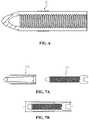
- FIGS. 7A and 7Bare horizontal cross-sectional views of a screw anchor assembly according to yet another embodiment of the present disclosure.
- Screw 20Screw threads 30, 100: Screw anchor 40: Anchor threads 50: Receiving part 60: One end of threaded anchor 70: Stopper part 80: Connecting part 91, 92, 93, 94: Division
- FIG. 1is a diagram showing a process of fixing the screw anchor assembly into the vertebra according to an embodiment of the present disclosure.
- FIG. 2is a schematic perspective view of a screw anchor of the screw anchor assembly according to an embodiment of the present disclosure.
- FIG. 3is a horizontal cross-sectional view of the screw anchor assembly according to an embodiment of the present disclosure.
- FIG. 4is a cross-sectional view taken along the line B-B′ of FIG. 3 .
- the screw anchor assemblyaccording to an embodiment of the present disclosure includes a screw anchor 30 and a screw 10 .
- the screw anchor 30is an element that is inserted into a predefined position of vertebra first instead of inserting the screw 10 directly, and allows the screw 10 to be inserted into a receiving part 50 inside to enable more secure fixation of the screw 10 into vertebra.
- the screw anchor 30has the receiving part 50 that receives the screw 10 therein in the lengthwise direction, and one end 60 that is inserted into vertebra is in a pointed conic shape to effectively insert the screw anchor 30 into vertebra.
- Anchor threads 40are formed on an inner surface defining the receiving part 50 of the screw anchor 30 , and the anchor threads 40 may be screw-coupled with screw threads 20 of the screw 10 as described below, and through this screw coupling, the screw 10 is received in the screw anchor 30 . Meanwhile, the pitch P 1 of the anchor threads 40 is equal to the pitch P 2 of the screw threads 20 to prevent damage of the screw anchor 30 and/or the screw 10 when the screw 10 is inserted into the screw anchor 30 through screw coupling.
- the screw anchor 30is composed of a plurality of divisions 91 , 92 , 93 , 94 formed along the lengthwise direction, a space formed by one end 60 of the screw anchor 30 and the plurality of divisions 91 , 92 , 93 , 94 connected to one end 60 , i.e., an inner part surrounded by the plurality of divisions 91 , 92 , 93 , 94 becomes the receiving part 50 , and in normal condition before the screw anchor 30 is inserted into vertebra, there are overlapping parts C between adjacent divisions.
- fixation of the screw anchor assembly into vertebrais semi-permanent and more secure, thereby producing effects on the reductions in reoperation rate and patients' physical and economic burden.
- a stopper part 70may be formed on the outer surface of the divisions 91 , 92 , 93 , 94 of the screw anchor 30 , and the stopper part 70 may be formed along the lengthwise direction of the screw anchor 30 , and may be formed on the outer surface of the divisions 91 , 92 , 93 , 94 in whole or in part. Furthermore, the stopper part 70 may have a slope surface, and the slope surface may slope toward one end 60 of the screw anchor 30 .
- the stopper part 70is formed on the outer surface of the divisions 91 , 92 , 93 , 94 , the friction coefficient and contact area of the screw anchor 30 with the bone surface increases and sufficient pull-out strength can be obtained, which as a result, can prevent the screw 10 inserted into the screw anchor 30 from slipping out of the bone.
- any material that is not harmful to human bodyis available, and a plastic material such as poly(methylmethacrylate) (PMMA) may be used, but recently development using calcium phosphate is in progress, and polyether ether ketone (PEEK), bone material (or bone substitute material; material that is transformed into bone over time) or artificial bone is available.
- PMMApoly(methylmethacrylate)
- PEEKpolyether ether ketone
- bone materialor bone substitute material; material that is transformed into bone over time
- artificial boneis available.
- the screw 10is a type of nail having the screw threads 20 formed in the lengthwise direction, and when it is inserted into the screw anchor 30 through screw coupling, it expands the receiving part 50 of the screw anchor 30 , and accordingly, the screw anchor 30 is fixed into the vertebra. As a result, fixation of the screw anchor 30 produces an effect on the fixation of the screw 10 into vertebra, thereby maintaining the spine in a desired shape.
- the pitch of the screw threads 20is equal to the pitch of the anchor threads 40 , damage of the screw anchor 30 and/or the screw 10 can be prevented when the screw 10 is inserted into the screw anchor 30 through screw coupling.
- any material that is not harmful to human bodyis available similar to the screw anchor 30 , and a plastic material such as poly(methylmethacrylate) (PMMA) may be used, but recently development using calcium phosphate is in progress, and polyether ether ketone (PEEK), bone material (or bone substitute material; material that is transformed into bone over time) or artificial bone is available.
- PMMApoly(methylmethacrylate)
- PEEKpolyether ether ketone
- spinal screw fixationis performed using the screw anchor assembly including the screw anchor 30 and the screw 10 described above, and specifically, to treat the damaged part of the spine, the screw anchor 30 is inserted and fixed into the pedicle or sacrum of vertebra in appropriate orientation and position first, and the screw 10 is screw coupled to the receiving part 50 of the inserted screw anchor 30 using a drive (not shown).
- FIG. 5is a vertical cross-sectional view of a screw anchor of the screw anchor assembly according to another embodiment of the present disclosure.
- the screw anchor assemblyaccording to another embodiment of the present disclosure further includes a connecting part 80 connecting the divisions 91 , 92 , 93 , 94 of the screw anchor 30 .
- the plurality of divisions 91 , 92 , 93 , 94 that makes up the screw anchor 30is separated with overlapping parts C therebetween, but adjacent divisions are connected by the connecting part 80 and thus have parts not separated from each other.
- the connecting part 80may connect the parts of adjacent divisions, and some or all adjacent divisions may have the connection of the connecting part 80 .
- the screw anchor assemblyaccording to another embodiment of the present disclosure includes the divisions 91 , 92 , 93 , 94 connected by the connecting part 80 as described above, when it is in normal condition, the plurality of divisions 91 , 92 , 93 , 94 is placed in fixed position relative to each other, and accordingly the screw anchor 30 can maintain its original shape.
- FIG. 6is a horizontal cross-sectional view of a screw anchor of the screw anchor assembly according to still another embodiment of the present disclosure.
- the surface of the screw anchor 30(i.e., the outer surface of the plurality of divisions) is roughening treated, and thus the screw anchor 30 includes a rough outer surface E.
- the rough outer surface E having undergone surface roughening treatmentmay be formed on the surface of the screw anchor 30 in whole or in part.
- FIGS. 7A and 7Bare horizontal cross-sectional views of the screw anchor assembly according to yet another embodiment of the present disclosure.
- a screw anchor 100 of the screw anchor assemblyhas the internal receiving part becoming narrower as it goes to one end that is inserted into the bone earlier. That is, as can be seen through FIG. 7A , the diameter L′ of the receiving part at the side of one end of the screw anchor 100 is smaller than the diameter L of the receiving part at the side of the other end opposite to one end.
- the receiving part of the screw anchor 100becomes narrower as it goes to one end, when the screw 10 is inserted into the screw anchor 100 , as it goes to the narrower end, the extent to which the screw anchor 100 spreads outward becomes greater, i.e., the outer diameter P′ of the screw anchor 100 at the side of one end becomes larger than the outer diameter P of the screw anchor 100 at the side of the other end, and thus the bond strength of the bone and the screw anchor 100 is further enhanced.
Landscapes
- Health & Medical Sciences (AREA)
- Orthopedic Medicine & Surgery (AREA)
- Life Sciences & Earth Sciences (AREA)
- Surgery (AREA)
- Neurology (AREA)
- Heart & Thoracic Surgery (AREA)
- Engineering & Computer Science (AREA)
- Biomedical Technology (AREA)
- Nuclear Medicine, Radiotherapy & Molecular Imaging (AREA)
- Medical Informatics (AREA)
- Molecular Biology (AREA)
- Animal Behavior & Ethology (AREA)
- General Health & Medical Sciences (AREA)
- Public Health (AREA)
- Veterinary Medicine (AREA)
- Surgical Instruments (AREA)
Abstract
Description
| <Detailed Description of Main Elements> |
| 10: Screw | 20: Screw | ||
| 30, 100: Screw anchor | 40: Anchor threads | ||
| 50: Receiving part | 60: One end of threaded anchor | ||
| 70: Stopper part | 80: Connecting | ||
| 91, 92, 93, 94: Division | |||
Claims (10)
Applications Claiming Priority (3)
| Application Number | Priority Date | Filing Date | Title |
|---|---|---|---|
| KR10-2015-0100783 | 2015-07-16 | ||
| KR1020150100783AKR101670768B1 (en) | 2015-07-16 | 2015-07-16 | Screw anchor assembly |
| PCT/KR2016/007473WO2017010757A1 (en) | 2015-07-16 | 2016-07-11 | Screw anchor assembly |
Publications (2)
| Publication Number | Publication Date |
|---|---|
| US20180199969A1 US20180199969A1 (en) | 2018-07-19 |
| US10575885B2true US10575885B2 (en) | 2020-03-03 |
Family
ID=57446172
Family Applications (1)
| Application Number | Title | Priority Date | Filing Date |
|---|---|---|---|
| US15/741,950Active2036-09-18US10575885B2 (en) | 2015-07-16 | 2016-07-11 | Screw anchor assembly |
Country Status (4)
| Country | Link |
|---|---|
| US (1) | US10575885B2 (en) |
| EP (1) | EP3323363B1 (en) |
| KR (1) | KR101670768B1 (en) |
| WO (1) | WO2017010757A1 (en) |
Cited By (2)
| Publication number | Priority date | Publication date | Assignee | Title |
|---|---|---|---|---|
| US11134989B2 (en) | 2014-05-28 | 2021-10-05 | Chap-Med, Inc. | Internal pedicle shield |
| US11540920B2 (en)* | 2019-10-17 | 2023-01-03 | Chap-Med, Inc. | Internal pedicle insulator |
Families Citing this family (4)
| Publication number | Priority date | Publication date | Assignee | Title |
|---|---|---|---|---|
| AT517141B1 (en)* | 2015-04-15 | 2019-08-15 | Pastl Klaus | bone screw |
| US11666367B2 (en) | 2018-05-30 | 2023-06-06 | Tushar Goradia | Guidance apparatus for implantation into bone and related methods of use |
| TR2021015278A2 (en)* | 2021-09-30 | 2021-10-21 | Hakan Cici | ORTHOPEDIC EXPANDABLE BLADE SCREW ANCHOR SYSTEM |
| US20230310038A1 (en)* | 2022-04-01 | 2023-10-05 | Globus Medical, Inc. | Expandable bone core for pedicle screw fixation |
Citations (103)
| Publication number | Priority date | Publication date | Assignee | Title |
|---|---|---|---|---|
| US4027932A (en) | 1974-05-25 | 1977-06-07 | Skf Industrial Trading And Development Company B.V. | Clutch release bearing |
| US4359318A (en) | 1981-12-18 | 1982-11-16 | Neal Gittleman | Dental implant |
| US4474516A (en) | 1981-05-25 | 1984-10-02 | Hilti Aktiengesellschaft | Anchor bolt assembly |
| US4678383A (en) | 1983-08-17 | 1987-07-07 | Hilti Aktiengesellschaft | Expansion anchor assembly |
| US5127407A (en) | 1989-08-17 | 1992-07-07 | Critikon, Inc. | Epidural oxygen sensor |
| US5265504A (en) | 1992-12-01 | 1993-11-30 | Hermann Fruhm | Cartridge type screwdriver |
| KR19990035953A (en) | 1995-08-22 | 1999-05-25 | 레이봉 알랭 | Screw Press-fit Sheet Anchors |
| US6171311B1 (en) | 1996-10-18 | 2001-01-09 | Marc Richelsoph | Transverse connector |
| US6249946B1 (en) | 2000-03-24 | 2001-06-26 | Small Steel Ring Company | Removal tool for internal and external retaining rings |
| US6258089B1 (en) | 1998-05-19 | 2001-07-10 | Alphatec Manufacturing, Inc. | Anterior cervical plate and fixation system |
| US6290701B1 (en) | 2000-01-11 | 2001-09-18 | Albert Enayati | Bioabsorbable rivet bone fastener |
| US6331179B1 (en) | 2000-01-06 | 2001-12-18 | Spinal Concepts, Inc. | System and method for stabilizing the human spine with a bone plate |
| US20020040241A1 (en) | 2000-06-14 | 2002-04-04 | Teppo Jarvinen | Fixation anchor |
| US6402757B1 (en) | 1999-03-12 | 2002-06-11 | Biomet, Inc. | Cannulated fastener system for repair of bone fracture |
| US6436100B1 (en) | 1998-08-07 | 2002-08-20 | J. Lee Berger | Cannulated internally threaded bone screw and reduction driver device |
| US20020151899A1 (en) | 2001-04-17 | 2002-10-17 | Bailey Kirk J. | Anterior cervical plating system |
| KR20020082009A (en) | 2001-04-23 | 2002-10-30 | 김지형 | Block plate for anterior cervical fusion |
| US20030135274A1 (en) | 1996-11-27 | 2003-07-17 | Jo Hays | Graft ligament anchor and method for attaching a graft ligament to a bone |
| US20030187440A1 (en) | 2002-03-12 | 2003-10-02 | Marc Richelsoph | Bone plate and screw retaining mechanism |
| US6652525B1 (en) | 1998-04-30 | 2003-11-25 | Sofamor S.N.C. | Anterior implant for the spine |
| KR20040001287A (en) | 2002-06-27 | 2004-01-07 | (주)태연메디칼 | Cervical vertebra fixation method and that system |
| US6767350B1 (en)* | 1998-07-25 | 2004-07-27 | Helke Lob | Fixing element for bone fragments |
| US6778861B1 (en) | 1999-06-23 | 2004-08-17 | Geot Gesellschaft Fur Elektro-Osteo-Therapie G.M.B.H. | Bone screw comprising a device for electrostimulation |
| US20040220571A1 (en) | 1998-04-30 | 2004-11-04 | Richard Assaker | Bone plate assembly |
| KR200367241Y1 (en) | 2004-08-27 | 2004-11-10 | 진동규 | Spinal fixation apparatus |
| US20040243207A1 (en) | 2003-05-30 | 2004-12-02 | Olson Donald R. | Medical implant systems |
| US20040267361A1 (en) | 2003-06-27 | 2004-12-30 | Donnelly Lisa M. | Flexible tibial sheath |
| KR20050023111A (en) | 2003-08-29 | 2005-03-09 | (주)태연메디칼 | Spine supporting instrument |
| US20050059972A1 (en) | 2003-09-16 | 2005-03-17 | Spineco, Inc., An Ohio Corporation | Bone anchor prosthesis and system |
| US20050192577A1 (en) | 2004-02-26 | 2005-09-01 | Pioneer Laboratories, Inc. | Bone plate system and methods |
| US20050216027A1 (en) | 2004-03-24 | 2005-09-29 | Suh Sean S | Extraction screwdriver |
| US20050261689A1 (en) | 2004-05-20 | 2005-11-24 | A-Spine Holding Group Corp. Ashg | Bone fixation device |
| US7029472B1 (en) | 1999-06-01 | 2006-04-18 | Fortin Frederic | Distraction device for the bones of children |
| US20060106390A1 (en) | 2004-11-18 | 2006-05-18 | Jensen David G | Composite bone fasteners |
| US20060149258A1 (en) | 2004-12-14 | 2006-07-06 | Sousa Joaquim P G | Surgical tool and method for fixation of ligaments |
| US20060217721A1 (en) | 2005-03-11 | 2006-09-28 | Suh Sean S | Translational hinged door plate system |
| US20060235410A1 (en) | 2005-04-15 | 2006-10-19 | Ralph James D | Surgical expansion fasteners |
| US20060247639A1 (en) | 2005-04-29 | 2006-11-02 | Sdgi Holdings, Inc. | Apparatus for retaining a bone anchor in a bone plate and method for use thereof |
| US20060293670A1 (en) | 2005-06-03 | 2006-12-28 | Smisson Hugh F Iii | Surgical stabilization system |
| US7194314B1 (en) | 2003-08-15 | 2007-03-20 | Northwestern University | Cochlear implant including a modiolar return electrode |
| US7235100B2 (en) | 2000-09-15 | 2007-06-26 | Tyco Healthcare Group Lp | Knotless tissue anchor |
| US20070233071A1 (en) | 2006-03-01 | 2007-10-04 | Sdgi Holdings, Inc. | Bone anchors having two or more portions exhibiting different performance characteristics and method of forming the same |
| KR20070112200A (en) | 2005-02-18 | 2007-11-22 | 워쏘우 오르쏘페딕 인코포레이티드 | Implants in surgical approach to the spine and methods for positioning them |
| US7302298B2 (en) | 2002-11-27 | 2007-11-27 | Northstar Neuroscience, Inc | Methods and systems employing intracranial electrodes for neurostimulation and/or electroencephalography |
| KR20080059920A (en) | 2006-12-26 | 2008-07-01 | 주식회사 엔에이치에스 | Spinal Fixation Device |
| US20080161864A1 (en) | 2006-09-29 | 2008-07-03 | Depuy Mitek, Inc. | Femoral fixation |
| US20080188897A1 (en) | 2006-10-02 | 2008-08-07 | The Cleveland Clinic Foundation | Fastener assembly |
| US20080221624A1 (en) | 2005-10-17 | 2008-09-11 | Gooch Hubert L | Systems and Methods for the Medical Treatment of Structural Tissue |
| KR20080105506A (en) | 2007-05-31 | 2008-12-04 | 주식회사 지에스메디칼 | Pedicle screw module |
| KR20090015933A (en) | 2006-04-24 | 2009-02-12 | 워쏘우 오르쏘페딕 인코포레이티드 | Connector device |
| US20090125072A1 (en) | 2007-11-13 | 2009-05-14 | Neubardt Seth L | Surgical bone screw construction |
| WO2009105106A2 (en) | 2008-02-21 | 2009-08-27 | Integrity Intellect, Inc. | Implant equipped for nerve location and method of use |
| KR20090111774A (en) | 2008-04-22 | 2009-10-27 | 비이더만 모테크 게엠베하 | Assembly tool for assembling bone fixation |
| US20090318970A1 (en) | 2008-06-19 | 2009-12-24 | Butler Michael S | Spinal Rod Connectors Configured to Retain Spinal Rods of Varying Diameters |
| US20100036467A1 (en) | 2006-05-01 | 2010-02-11 | Neue Magnetodyn Gmbh | Stimulation device for osteosynthesis and endoprosthetics |
| US7662154B2 (en) | 2005-09-16 | 2010-02-16 | Blackstone Medical, Inc. | Anterior cervical plating system |
| US20100049256A1 (en) | 2007-01-30 | 2010-02-25 | Dong Myung Jeon | Anterior cerivcal plating system |
| US20100106198A1 (en) | 2008-10-23 | 2010-04-29 | Warsaw Orthopedic, Inc | Nerve stimulating bone screw |
| US20100121383A1 (en) | 2008-11-10 | 2010-05-13 | Todd Stanaford | Method, system, and apparatus for mammalian bony segment stabilization |
| KR20100124709A (en) | 2007-12-21 | 2010-11-29 | 앵쁠라네 | Device for anchoring a tissue in a bone |
| US20110022097A1 (en) | 2009-07-24 | 2011-01-27 | Spinal USA LLC | Bone plate screw-blocking systems and methods |
| US20110029023A1 (en) | 2009-07-30 | 2011-02-03 | Clariance | Slide-type anti-backout device for prosthesis |
| US20110106159A1 (en) | 2008-06-05 | 2011-05-05 | Seaspine, Inc. | Spinal fixation plate assembly |
| US20110144702A1 (en) | 2004-04-20 | 2011-06-16 | Spineco, Inc. | Implant device |
| US20110152934A1 (en) | 2009-12-23 | 2011-06-23 | Asaad Wagdy W | Transconnector for coupling first and second spinal fixation elements |
| JP2011139901A (en) | 2010-01-08 | 2011-07-21 | Biedermann Motech Gmbh & Co Kg | Bone screw |
| US20110230885A1 (en) | 2010-03-19 | 2011-09-22 | Nextremity Solutions, Llc | Dynamic bone plate |
| US20110264151A1 (en) | 2010-04-26 | 2011-10-27 | Timothy Davis | Bone fixation device and method of validating its proper placement |
| KR20120039622A (en) | 2009-06-17 | 2012-04-25 | 신세스 게엠바하 | Revision connector for spinal constructs |
| KR20120040309A (en) | 2010-10-19 | 2012-04-27 | 인하대학교 산학협력단 | Ballon anchor reinforcing pedicle screw in osteoporotic spine |
| KR20120052265A (en) | 2009-07-06 | 2012-05-23 | 신세스 게엠바하 | Expandable fixation assemblies |
| KR20120057758A (en) | 2010-11-27 | 2012-06-07 | 서울대학교산학협력단 | Implant for neurotization by lectrostimulation |
| US20120185001A1 (en) | 2011-01-14 | 2012-07-19 | Warsaw Orthopedic, Inc. | Bone Anchors Compatible for Use with Neural Integrity Monitoring Systems and Procedures |
| US20120232595A1 (en) | 2011-03-07 | 2012-09-13 | Tyler HOLSCHLAG | Fastener retention system for spinal plates |
| US20120265258A1 (en)* | 2011-04-14 | 2012-10-18 | Brian Garvey | Expanding Spinal Anchor |
| US20120271363A1 (en) | 2009-11-05 | 2012-10-25 | The Johns Hopkins University | Universally deployable and expandable bone screw anchor |
| US20120289978A1 (en) | 2011-05-13 | 2012-11-15 | Warsaw Orthopedic, Inc. | Retaining mechansim |
| KR20130004669A (en) | 2011-07-04 | 2013-01-14 | 주식회사 솔고 바이오메디칼 | Instrument for fixing of cervical vertebrae |
| US20130023936A1 (en) | 2011-07-19 | 2013-01-24 | Moti Altarac | Anterior cervical plate |
| KR20130015081A (en) | 2011-08-02 | 2013-02-13 | 전남대학교산학협력단 | Medical screw assembly having screw line structure of rake type |
| US20130041413A1 (en) | 2010-11-28 | 2013-02-14 | Shandong Hangwei Orthopedics Medical Instrument Co., Ltd. | Universal locking and compression device for bone plate |
| US8454667B2 (en) | 2010-12-16 | 2013-06-04 | Warsaw Orhtopedic, Inc. | Retaining mechanism |
| US20130231704A1 (en) | 2010-11-10 | 2013-09-05 | Zimmer Spine | Bone anchor |
| US20130304067A1 (en) | 2012-05-10 | 2013-11-14 | Spinal Simplicity Llc | Dynamic bone fracture plates |
| KR101331429B1 (en) | 2012-08-03 | 2013-11-21 | 주식회사 솔고 바이오메디칼 | Snap type fixing apparatus for cervical spine |
| US20130325074A1 (en) | 2012-06-05 | 2013-12-05 | Blackstone Medical, Inc. | Orthopedic devices with a locking mechanism |
| KR20140003938A (en) | 2012-07-02 | 2014-01-10 | 한생수 | Anchor bolt |
| US8628325B2 (en) | 2006-09-03 | 2014-01-14 | Dentack Impants Ltd. | Expandable dental implants of high surface area and methods of expanding the same |
| KR20140018796A (en) | 2012-08-03 | 2014-02-13 | 주식회사 솔고 바이오메디칼 | Apparatus for fixing a cervical spine having self tension part |
| US20140066997A1 (en) | 2012-08-31 | 2014-03-06 | Warsaw Orthopedic, Inc. | Retaining mechanism |
| KR20140052320A (en) | 2012-10-24 | 2014-05-07 | 주식회사 지에스메디칼 | Cervical plate |
| KR101413732B1 (en) | 2007-02-23 | 2014-07-01 | 비이더만 테크놀로지스 게엠베하 & 코. 카게 | Stabilization device for stabilization of vertebrae and rod connector used in the device |
| US8906077B2 (en) | 2007-11-09 | 2014-12-09 | Stryker Spine | Cervical plate with a feedback device for selective association with bone screw blocking mechanism |
| US8940030B1 (en) | 2011-01-28 | 2015-01-27 | Nuvasive, Inc. | Spinal fixation system and related methods |
| US8956394B1 (en) | 2014-08-05 | 2015-02-17 | Woven Orthopedic Technologies, Llc | Woven retention devices, systems and methods |
| US20150134013A1 (en) | 2013-11-13 | 2015-05-14 | Kamaljit S. Paul | Bone treatment implants, and springs therefore |
| US20150201982A1 (en) | 2014-01-20 | 2015-07-23 | Neurostructures, Inc. | Anterior cervical plate |
| US20150216573A1 (en) | 2013-01-16 | 2015-08-06 | Spinefrontier, Inc | Bone fastener for a spinal fixation assembly |
| US20150230838A1 (en) | 2012-08-28 | 2015-08-20 | Koc Universitesi | Bone plate |
| KR20150120105A (en) | 2014-04-17 | 2015-10-27 | 경북대학교 산학협력단 | Screw fixing apparatus |
| US20160206351A1 (en) | 2014-08-11 | 2016-07-21 | Corentec Co., Ltd. | Spine fixing apparatus |
| US9775652B2 (en) | 2014-02-20 | 2017-10-03 | Mastros Innovations, Llc | Lateral plate |
| US9943341B2 (en) | 2013-07-16 | 2018-04-17 | K2M, Llc | Retention plate member for a spinal plate system |
Family Cites Families (1)
| Publication number | Priority date | Publication date | Assignee | Title |
|---|---|---|---|---|
| CA2722607A1 (en)* | 2008-04-28 | 2009-11-05 | Stephen J. Lewis | Anchor for use with orthopedic screw |
- 2015
- 2015-07-16KRKR1020150100783Apatent/KR101670768B1/enactiveActive
- 2016
- 2016-07-11WOPCT/KR2016/007473patent/WO2017010757A1/ennot_activeCeased
- 2016-07-11USUS15/741,950patent/US10575885B2/enactiveActive
- 2016-07-11EPEP16824674.2Apatent/EP3323363B1/enactiveActive
Patent Citations (120)
| Publication number | Priority date | Publication date | Assignee | Title |
|---|---|---|---|---|
| US4027932A (en) | 1974-05-25 | 1977-06-07 | Skf Industrial Trading And Development Company B.V. | Clutch release bearing |
| US4474516A (en) | 1981-05-25 | 1984-10-02 | Hilti Aktiengesellschaft | Anchor bolt assembly |
| US4359318A (en) | 1981-12-18 | 1982-11-16 | Neal Gittleman | Dental implant |
| US4678383A (en) | 1983-08-17 | 1987-07-07 | Hilti Aktiengesellschaft | Expansion anchor assembly |
| US5127407A (en) | 1989-08-17 | 1992-07-07 | Critikon, Inc. | Epidural oxygen sensor |
| US5265504A (en) | 1992-12-01 | 1993-11-30 | Hermann Fruhm | Cartridge type screwdriver |
| KR19990035953A (en) | 1995-08-22 | 1999-05-25 | 레이봉 알랭 | Screw Press-fit Sheet Anchors |
| US6171311B1 (en) | 1996-10-18 | 2001-01-09 | Marc Richelsoph | Transverse connector |
| US20030135274A1 (en) | 1996-11-27 | 2003-07-17 | Jo Hays | Graft ligament anchor and method for attaching a graft ligament to a bone |
| US6652525B1 (en) | 1998-04-30 | 2003-11-25 | Sofamor S.N.C. | Anterior implant for the spine |
| US20040220571A1 (en) | 1998-04-30 | 2004-11-04 | Richard Assaker | Bone plate assembly |
| US6258089B1 (en) | 1998-05-19 | 2001-07-10 | Alphatec Manufacturing, Inc. | Anterior cervical plate and fixation system |
| US6767350B1 (en)* | 1998-07-25 | 2004-07-27 | Helke Lob | Fixing element for bone fragments |
| US6436100B1 (en) | 1998-08-07 | 2002-08-20 | J. Lee Berger | Cannulated internally threaded bone screw and reduction driver device |
| US6402757B1 (en) | 1999-03-12 | 2002-06-11 | Biomet, Inc. | Cannulated fastener system for repair of bone fracture |
| US7029472B1 (en) | 1999-06-01 | 2006-04-18 | Fortin Frederic | Distraction device for the bones of children |
| US6778861B1 (en) | 1999-06-23 | 2004-08-17 | Geot Gesellschaft Fur Elektro-Osteo-Therapie G.M.B.H. | Bone screw comprising a device for electrostimulation |
| US6331179B1 (en) | 2000-01-06 | 2001-12-18 | Spinal Concepts, Inc. | System and method for stabilizing the human spine with a bone plate |
| US6290701B1 (en) | 2000-01-11 | 2001-09-18 | Albert Enayati | Bioabsorbable rivet bone fastener |
| US6249946B1 (en) | 2000-03-24 | 2001-06-26 | Small Steel Ring Company | Removal tool for internal and external retaining rings |
| US20020040241A1 (en) | 2000-06-14 | 2002-04-04 | Teppo Jarvinen | Fixation anchor |
| US7235100B2 (en) | 2000-09-15 | 2007-06-26 | Tyco Healthcare Group Lp | Knotless tissue anchor |
| US20020151899A1 (en) | 2001-04-17 | 2002-10-17 | Bailey Kirk J. | Anterior cervical plating system |
| KR20020082009A (en) | 2001-04-23 | 2002-10-30 | 김지형 | Block plate for anterior cervical fusion |
| US20030187440A1 (en) | 2002-03-12 | 2003-10-02 | Marc Richelsoph | Bone plate and screw retaining mechanism |
| KR20040001287A (en) | 2002-06-27 | 2004-01-07 | (주)태연메디칼 | Cervical vertebra fixation method and that system |
| US7302298B2 (en) | 2002-11-27 | 2007-11-27 | Northstar Neuroscience, Inc | Methods and systems employing intracranial electrodes for neurostimulation and/or electroencephalography |
| US20040243207A1 (en) | 2003-05-30 | 2004-12-02 | Olson Donald R. | Medical implant systems |
| US20040267361A1 (en) | 2003-06-27 | 2004-12-30 | Donnelly Lisa M. | Flexible tibial sheath |
| US7194314B1 (en) | 2003-08-15 | 2007-03-20 | Northwestern University | Cochlear implant including a modiolar return electrode |
| KR20050023111A (en) | 2003-08-29 | 2005-03-09 | (주)태연메디칼 | Spine supporting instrument |
| US20050059972A1 (en) | 2003-09-16 | 2005-03-17 | Spineco, Inc., An Ohio Corporation | Bone anchor prosthesis and system |
| US20060161157A1 (en) | 2004-02-26 | 2006-07-20 | Lawrence Mosca | Bone plate system and methods |
| US20050192577A1 (en) | 2004-02-26 | 2005-09-01 | Pioneer Laboratories, Inc. | Bone plate system and methods |
| KR20070026472A (en) | 2004-03-24 | 2007-03-08 | 신테스 (유.에스.에이.) | Extraction screw driver |
| US20050216027A1 (en) | 2004-03-24 | 2005-09-29 | Suh Sean S | Extraction screwdriver |
| US20110144702A1 (en) | 2004-04-20 | 2011-06-16 | Spineco, Inc. | Implant device |
| US20050261689A1 (en) | 2004-05-20 | 2005-11-24 | A-Spine Holding Group Corp. Ashg | Bone fixation device |
| KR200367241Y1 (en) | 2004-08-27 | 2004-11-10 | 진동규 | Spinal fixation apparatus |
| US20060106390A1 (en) | 2004-11-18 | 2006-05-18 | Jensen David G | Composite bone fasteners |
| US20060149258A1 (en) | 2004-12-14 | 2006-07-06 | Sousa Joaquim P G | Surgical tool and method for fixation of ligaments |
| KR20070112200A (en) | 2005-02-18 | 2007-11-22 | 워쏘우 오르쏘페딕 인코포레이티드 | Implants in surgical approach to the spine and methods for positioning them |
| US20060217721A1 (en) | 2005-03-11 | 2006-09-28 | Suh Sean S | Translational hinged door plate system |
| US20060235410A1 (en) | 2005-04-15 | 2006-10-19 | Ralph James D | Surgical expansion fasteners |
| US20060247639A1 (en) | 2005-04-29 | 2006-11-02 | Sdgi Holdings, Inc. | Apparatus for retaining a bone anchor in a bone plate and method for use thereof |
| US8057521B2 (en) | 2005-06-03 | 2011-11-15 | Southern Spine, Llc | Surgical stabilization system |
| US20060293670A1 (en) | 2005-06-03 | 2006-12-28 | Smisson Hugh F Iii | Surgical stabilization system |
| US7662154B2 (en) | 2005-09-16 | 2010-02-16 | Blackstone Medical, Inc. | Anterior cervical plating system |
| US20080221624A1 (en) | 2005-10-17 | 2008-09-11 | Gooch Hubert L | Systems and Methods for the Medical Treatment of Structural Tissue |
| US20070233071A1 (en) | 2006-03-01 | 2007-10-04 | Sdgi Holdings, Inc. | Bone anchors having two or more portions exhibiting different performance characteristics and method of forming the same |
| KR20090015933A (en) | 2006-04-24 | 2009-02-12 | 워쏘우 오르쏘페딕 인코포레이티드 | Connector device |
| US20100036467A1 (en) | 2006-05-01 | 2010-02-11 | Neue Magnetodyn Gmbh | Stimulation device for osteosynthesis and endoprosthetics |
| US8628325B2 (en) | 2006-09-03 | 2014-01-14 | Dentack Impants Ltd. | Expandable dental implants of high surface area and methods of expanding the same |
| US20080161864A1 (en) | 2006-09-29 | 2008-07-03 | Depuy Mitek, Inc. | Femoral fixation |
| US20080188897A1 (en) | 2006-10-02 | 2008-08-07 | The Cleveland Clinic Foundation | Fastener assembly |
| KR100850322B1 (en) | 2006-12-26 | 2008-08-12 | 주식회사 엔에이치에스 | Apparatus for percutaneous pedicle screw fixation |
| KR20080059920A (en) | 2006-12-26 | 2008-07-01 | 주식회사 엔에이치에스 | Spinal Fixation Device |
| US20100049256A1 (en) | 2007-01-30 | 2010-02-25 | Dong Myung Jeon | Anterior cerivcal plating system |
| KR101413732B1 (en) | 2007-02-23 | 2014-07-01 | 비이더만 테크놀로지스 게엠베하 & 코. 카게 | Stabilization device for stabilization of vertebrae and rod connector used in the device |
| KR20080105506A (en) | 2007-05-31 | 2008-12-04 | 주식회사 지에스메디칼 | Pedicle screw module |
| KR100872529B1 (en) | 2007-05-31 | 2008-12-08 | 주식회사 지에스메디칼 | Pedicle screw module |
| WO2008146981A1 (en) | 2007-05-31 | 2008-12-04 | Gs Medical Co., Ltd. | A spinal screw module |
| US9918760B2 (en) | 2007-11-09 | 2018-03-20 | Stryker European Holdings I, Llc | Cervical plate with a feedback device for selective association with bone screw blocking mechanism |
| US8906077B2 (en) | 2007-11-09 | 2014-12-09 | Stryker Spine | Cervical plate with a feedback device for selective association with bone screw blocking mechanism |
| US20090125072A1 (en) | 2007-11-13 | 2009-05-14 | Neubardt Seth L | Surgical bone screw construction |
| KR20100124709A (en) | 2007-12-21 | 2010-11-29 | 앵쁠라네 | Device for anchoring a tissue in a bone |
| WO2009105106A2 (en) | 2008-02-21 | 2009-08-27 | Integrity Intellect, Inc. | Implant equipped for nerve location and method of use |
| KR20090111774A (en) | 2008-04-22 | 2009-10-27 | 비이더만 모테크 게엠베하 | Assembly tool for assembling bone fixation |
| US20110106159A1 (en) | 2008-06-05 | 2011-05-05 | Seaspine, Inc. | Spinal fixation plate assembly |
| US20090318970A1 (en) | 2008-06-19 | 2009-12-24 | Butler Michael S | Spinal Rod Connectors Configured to Retain Spinal Rods of Varying Diameters |
| US20100106198A1 (en) | 2008-10-23 | 2010-04-29 | Warsaw Orthopedic, Inc | Nerve stimulating bone screw |
| US20100121383A1 (en) | 2008-11-10 | 2010-05-13 | Todd Stanaford | Method, system, and apparatus for mammalian bony segment stabilization |
| KR20120039622A (en) | 2009-06-17 | 2012-04-25 | 신세스 게엠바하 | Revision connector for spinal constructs |
| KR20120052265A (en) | 2009-07-06 | 2012-05-23 | 신세스 게엠바하 | Expandable fixation assemblies |
| US20110022097A1 (en) | 2009-07-24 | 2011-01-27 | Spinal USA LLC | Bone plate screw-blocking systems and methods |
| US8419777B2 (en) | 2009-07-24 | 2013-04-16 | Spinal Usa, Inc. | Bone plate screw-blocking systems and methods |
| US20110029023A1 (en) | 2009-07-30 | 2011-02-03 | Clariance | Slide-type anti-backout device for prosthesis |
| US20120271363A1 (en) | 2009-11-05 | 2012-10-25 | The Johns Hopkins University | Universally deployable and expandable bone screw anchor |
| US20110152934A1 (en) | 2009-12-23 | 2011-06-23 | Asaad Wagdy W | Transconnector for coupling first and second spinal fixation elements |
| JP2011139901A (en) | 2010-01-08 | 2011-07-21 | Biedermann Motech Gmbh & Co Kg | Bone screw |
| US20110230885A1 (en) | 2010-03-19 | 2011-09-22 | Nextremity Solutions, Llc | Dynamic bone plate |
| US8758347B2 (en) | 2010-03-19 | 2014-06-24 | Nextremity Solutions, Inc. | Dynamic bone plate |
| KR20130016303A (en) | 2010-03-19 | 2013-02-14 | 넥스트레미티 솔루션스 엘엘씨 | Dynamic corrugated plate |
| US20110264151A1 (en) | 2010-04-26 | 2011-10-27 | Timothy Davis | Bone fixation device and method of validating its proper placement |
| KR20120040309A (en) | 2010-10-19 | 2012-04-27 | 인하대학교 산학협력단 | Ballon anchor reinforcing pedicle screw in osteoporotic spine |
| KR101142895B1 (en) | 2010-10-19 | 2012-05-10 | 인하대학교 산학협력단 | Ballon anchor reinforcing pedicle screw in osteoporotic spine |
| US20130231704A1 (en) | 2010-11-10 | 2013-09-05 | Zimmer Spine | Bone anchor |
| KR20120057758A (en) | 2010-11-27 | 2012-06-07 | 서울대학교산학협력단 | Implant for neurotization by lectrostimulation |
| US20130041413A1 (en) | 2010-11-28 | 2013-02-14 | Shandong Hangwei Orthopedics Medical Instrument Co., Ltd. | Universal locking and compression device for bone plate |
| US8454667B2 (en) | 2010-12-16 | 2013-06-04 | Warsaw Orhtopedic, Inc. | Retaining mechanism |
| US20120185001A1 (en) | 2011-01-14 | 2012-07-19 | Warsaw Orthopedic, Inc. | Bone Anchors Compatible for Use with Neural Integrity Monitoring Systems and Procedures |
| US8940030B1 (en) | 2011-01-28 | 2015-01-27 | Nuvasive, Inc. | Spinal fixation system and related methods |
| US20120232595A1 (en) | 2011-03-07 | 2012-09-13 | Tyler HOLSCHLAG | Fastener retention system for spinal plates |
| JP2014517739A (en) | 2011-04-14 | 2014-07-24 | グローバス メディカル インコーポレイティッド | Expandable spinal anchor |
| US20120265258A1 (en)* | 2011-04-14 | 2012-10-18 | Brian Garvey | Expanding Spinal Anchor |
| US20120289978A1 (en) | 2011-05-13 | 2012-11-15 | Warsaw Orthopedic, Inc. | Retaining mechansim |
| KR20130004669A (en) | 2011-07-04 | 2013-01-14 | 주식회사 솔고 바이오메디칼 | Instrument for fixing of cervical vertebrae |
| US9918749B2 (en) | 2011-07-19 | 2018-03-20 | Howmedica Osteonics Corp. | Anterior cervical plate |
| US20130023936A1 (en) | 2011-07-19 | 2013-01-24 | Moti Altarac | Anterior cervical plate |
| KR20130015081A (en) | 2011-08-02 | 2013-02-13 | 전남대학교산학협력단 | Medical screw assembly having screw line structure of rake type |
| US20130304067A1 (en) | 2012-05-10 | 2013-11-14 | Spinal Simplicity Llc | Dynamic bone fracture plates |
| US9265531B2 (en) | 2012-06-05 | 2016-02-23 | Blackstone Medical, Inc. | Orthopedic devices with a locking mechanism |
| US20160166295A1 (en) | 2012-06-05 | 2016-06-16 | Blackstone Medical, Inc. | Orthopedic devices with a locking mechanism |
| US20130325074A1 (en) | 2012-06-05 | 2013-12-05 | Blackstone Medical, Inc. | Orthopedic devices with a locking mechanism |
| KR20140003938A (en) | 2012-07-02 | 2014-01-10 | 한생수 | Anchor bolt |
| KR20140018796A (en) | 2012-08-03 | 2014-02-13 | 주식회사 솔고 바이오메디칼 | Apparatus for fixing a cervical spine having self tension part |
| KR101331429B1 (en) | 2012-08-03 | 2013-11-21 | 주식회사 솔고 바이오메디칼 | Snap type fixing apparatus for cervical spine |
| US20150230838A1 (en) | 2012-08-28 | 2015-08-20 | Koc Universitesi | Bone plate |
| US20140066997A1 (en) | 2012-08-31 | 2014-03-06 | Warsaw Orthopedic, Inc. | Retaining mechanism |
| US8932335B2 (en) | 2012-08-31 | 2015-01-13 | Warsaw Orthopedic, Inc. | Retaining mechanism |
| KR20140052320A (en) | 2012-10-24 | 2014-05-07 | 주식회사 지에스메디칼 | Cervical plate |
| US20150216573A1 (en) | 2013-01-16 | 2015-08-06 | Spinefrontier, Inc | Bone fastener for a spinal fixation assembly |
| US9943341B2 (en) | 2013-07-16 | 2018-04-17 | K2M, Llc | Retention plate member for a spinal plate system |
| US20150134013A1 (en) | 2013-11-13 | 2015-05-14 | Kamaljit S. Paul | Bone treatment implants, and springs therefore |
| US20150201982A1 (en) | 2014-01-20 | 2015-07-23 | Neurostructures, Inc. | Anterior cervical plate |
| US9629664B2 (en) | 2014-01-20 | 2017-04-25 | Neurostructures, Inc. | Anterior cervical plate |
| US9775652B2 (en) | 2014-02-20 | 2017-10-03 | Mastros Innovations, Llc | Lateral plate |
| KR20150120105A (en) | 2014-04-17 | 2015-10-27 | 경북대학교 산학협력단 | Screw fixing apparatus |
| US8956394B1 (en) | 2014-08-05 | 2015-02-17 | Woven Orthopedic Technologies, Llc | Woven retention devices, systems and methods |
| US20160206351A1 (en) | 2014-08-11 | 2016-07-21 | Corentec Co., Ltd. | Spine fixing apparatus |
Cited By (4)
| Publication number | Priority date | Publication date | Assignee | Title |
|---|---|---|---|---|
| US11134989B2 (en) | 2014-05-28 | 2021-10-05 | Chap-Med, Inc. | Internal pedicle shield |
| US11540920B2 (en)* | 2019-10-17 | 2023-01-03 | Chap-Med, Inc. | Internal pedicle insulator |
| US20230127165A1 (en)* | 2019-10-17 | 2023-04-27 | Chap-Med, Inc. | Internal pedicle insulator |
| US12161556B2 (en)* | 2019-10-17 | 2024-12-10 | Chap-Med, Inc. | Internal pedicle insulator |
Also Published As
| Publication number | Publication date |
|---|---|
| US20180199969A1 (en) | 2018-07-19 |
| WO2017010757A1 (en) | 2017-01-19 |
| EP3323363B1 (en) | 2020-05-27 |
| KR101670768B1 (en) | 2016-10-31 |
| EP3323363A4 (en) | 2019-06-26 |
| EP3323363A1 (en) | 2018-05-23 |
Similar Documents
| Publication | Publication Date | Title |
|---|---|---|
| US10575885B2 (en) | Screw anchor assembly | |
| US10874445B2 (en) | Screw fixing apparatus | |
| US8617220B2 (en) | System and method for correction of a spinal disorder | |
| EP2964115B1 (en) | Bone fastener | |
| US11083509B2 (en) | Screw anchor assembly and method of using the same in pedicle screw fixation | |
| KR101599607B1 (en) | Screw fixing apparatus | |
| US9271758B2 (en) | Bone fastener and methods of use | |
| US8641736B2 (en) | Vertebral fastener system | |
| US9592081B2 (en) | System and method for stabilizing a posterior fusion over motion segments | |
| US20160106477A1 (en) | Spinal implant system and method | |
| US8961566B2 (en) | Vertebral construct and methods of use | |
| US9615868B2 (en) | Bone fastener and methods of use | |
| US10045796B2 (en) | Spinal correction system and method | |
| CA2721962A1 (en) | Posterior spinal fastener | |
| JP2016512094A (en) | Pedicle screw with reverse spiral cut and method | |
| US9918763B2 (en) | Bone fixation element and methods of use | |
| US9387026B2 (en) | Bone fastener and methods of use | |
| US9848919B2 (en) | Spinal construct and methods of use | |
| US10687862B2 (en) | Spinal implant connector and methods |
Legal Events
| Date | Code | Title | Description |
|---|---|---|---|
| AS | Assignment | Owner name:KYUNGPOOK NATIONAL UNIVERSITY INDUSTRY-ACADEMIC COOPERATION FOUNDATION, KOREA, REPUBLIC OF Free format text:ASSIGNMENT OF ASSIGNORS INTEREST;ASSIGNOR:KIM, KYOUNGTAE;REEL/FRAME:044538/0826 Effective date:20180102 Owner name:KYUNGPOOK NATIONAL UNIVERSITY INDUSTRY-ACADEMIC CO Free format text:ASSIGNMENT OF ASSIGNORS INTEREST;ASSIGNOR:KIM, KYOUNGTAE;REEL/FRAME:044538/0826 Effective date:20180102 | |
| FEPP | Fee payment procedure | Free format text:ENTITY STATUS SET TO UNDISCOUNTED (ORIGINAL EVENT CODE: BIG.); ENTITY STATUS OF PATENT OWNER: SMALL ENTITY | |
| FEPP | Fee payment procedure | Free format text:ENTITY STATUS SET TO SMALL (ORIGINAL EVENT CODE: SMAL); ENTITY STATUS OF PATENT OWNER: SMALL ENTITY | |
| STPP | Information on status: patent application and granting procedure in general | Free format text:DOCKETED NEW CASE - READY FOR EXAMINATION | |
| STPP | Information on status: patent application and granting procedure in general | Free format text:NON FINAL ACTION MAILED | |
| STPP | Information on status: patent application and granting procedure in general | Free format text:NOTICE OF ALLOWANCE MAILED -- APPLICATION RECEIVED IN OFFICE OF PUBLICATIONS | |
| STPP | Information on status: patent application and granting procedure in general | Free format text:PUBLICATIONS -- ISSUE FEE PAYMENT RECEIVED | |
| STCF | Information on status: patent grant | Free format text:PATENTED CASE | |
| MAFP | Maintenance fee payment | Free format text:PAYMENT OF MAINTENANCE FEE, 4TH YR, SMALL ENTITY (ORIGINAL EVENT CODE: M2551); ENTITY STATUS OF PATENT OWNER: SMALL ENTITY Year of fee payment:4 |