US10575765B2 - Analyte-sensing device - Google Patents
Analyte-sensing deviceDownload PDFInfo
- Publication number
- US10575765B2 US10575765B2US15/517,318US201515517318AUS10575765B2US 10575765 B2US10575765 B2US 10575765B2US 201515517318 AUS201515517318 AUS 201515517318AUS 10575765 B2US10575765 B2US 10575765B2
- Authority
- US
- United States
- Prior art keywords
- implantable
- unit
- light
- fluorescent
- sensor
- Prior art date
- Legal status (The legal status is an assumption and is not a legal conclusion. Google has not performed a legal analysis and makes no representation as to the accuracy of the status listed.)
- Expired - Fee Related, expires
Links
Images


Classifications
- A—HUMAN NECESSITIES
- A61—MEDICAL OR VETERINARY SCIENCE; HYGIENE
- A61B—DIAGNOSIS; SURGERY; IDENTIFICATION
- A61B5/00—Measuring for diagnostic purposes; Identification of persons
- A61B5/145—Measuring characteristics of blood in vivo, e.g. gas concentration or pH-value ; Measuring characteristics of body fluids or tissues, e.g. interstitial fluid or cerebral tissue
- A61B5/1455—Measuring characteristics of blood in vivo, e.g. gas concentration or pH-value ; Measuring characteristics of body fluids or tissues, e.g. interstitial fluid or cerebral tissue using optical sensors, e.g. spectral photometrical oximeters
- A61B5/14551—Measuring characteristics of blood in vivo, e.g. gas concentration or pH-value ; Measuring characteristics of body fluids or tissues, e.g. interstitial fluid or cerebral tissue using optical sensors, e.g. spectral photometrical oximeters for measuring blood gases
- A61B5/14556—Measuring characteristics of blood in vivo, e.g. gas concentration or pH-value ; Measuring characteristics of body fluids or tissues, e.g. interstitial fluid or cerebral tissue using optical sensors, e.g. spectral photometrical oximeters for measuring blood gases by fluorescence
- A—HUMAN NECESSITIES
- A61—MEDICAL OR VETERINARY SCIENCE; HYGIENE
- A61B—DIAGNOSIS; SURGERY; IDENTIFICATION
- A61B5/00—Measuring for diagnostic purposes; Identification of persons
- A61B5/0059—Measuring for diagnostic purposes; Identification of persons using light, e.g. diagnosis by transillumination, diascopy, fluorescence
- A61B5/0071—Measuring for diagnostic purposes; Identification of persons using light, e.g. diagnosis by transillumination, diascopy, fluorescence by measuring fluorescence emission
- A—HUMAN NECESSITIES
- A61—MEDICAL OR VETERINARY SCIENCE; HYGIENE
- A61B—DIAGNOSIS; SURGERY; IDENTIFICATION
- A61B5/00—Measuring for diagnostic purposes; Identification of persons
- A61B5/145—Measuring characteristics of blood in vivo, e.g. gas concentration or pH-value ; Measuring characteristics of body fluids or tissues, e.g. interstitial fluid or cerebral tissue
- A61B5/14532—Measuring characteristics of blood in vivo, e.g. gas concentration or pH-value ; Measuring characteristics of body fluids or tissues, e.g. interstitial fluid or cerebral tissue for measuring glucose, e.g. by tissue impedance measurement
- A—HUMAN NECESSITIES
- A61—MEDICAL OR VETERINARY SCIENCE; HYGIENE
- A61B—DIAGNOSIS; SURGERY; IDENTIFICATION
- A61B5/00—Measuring for diagnostic purposes; Identification of persons
- A61B5/145—Measuring characteristics of blood in vivo, e.g. gas concentration or pH-value ; Measuring characteristics of body fluids or tissues, e.g. interstitial fluid or cerebral tissue
- A61B5/1455—Measuring characteristics of blood in vivo, e.g. gas concentration or pH-value ; Measuring characteristics of body fluids or tissues, e.g. interstitial fluid or cerebral tissue using optical sensors, e.g. spectral photometrical oximeters
- A61B5/1459—Measuring characteristics of blood in vivo, e.g. gas concentration or pH-value ; Measuring characteristics of body fluids or tissues, e.g. interstitial fluid or cerebral tissue using optical sensors, e.g. spectral photometrical oximeters invasive, e.g. introduced into the body by a catheter
- G—PHYSICS
- G01—MEASURING; TESTING
- G01N—INVESTIGATING OR ANALYSING MATERIALS BY DETERMINING THEIR CHEMICAL OR PHYSICAL PROPERTIES
- G01N21/00—Investigating or analysing materials by the use of optical means, i.e. using sub-millimetre waves, infrared, visible or ultraviolet light
- G01N21/62—Systems in which the material investigated is excited whereby it emits light or causes a change in wavelength of the incident light
- G01N21/63—Systems in which the material investigated is excited whereby it emits light or causes a change in wavelength of the incident light optically excited
- G01N21/64—Fluorescence; Phosphorescence
- G01N21/6428—Measuring fluorescence of fluorescent products of reactions or of fluorochrome labelled reactive substances, e.g. measuring quenching effects, using measuring "optrodes"
- G—PHYSICS
- G01—MEASURING; TESTING
- G01N—INVESTIGATING OR ANALYSING MATERIALS BY DETERMINING THEIR CHEMICAL OR PHYSICAL PROPERTIES
- G01N21/00—Investigating or analysing materials by the use of optical means, i.e. using sub-millimetre waves, infrared, visible or ultraviolet light
- G01N21/62—Systems in which the material investigated is excited whereby it emits light or causes a change in wavelength of the incident light
- G01N21/63—Systems in which the material investigated is excited whereby it emits light or causes a change in wavelength of the incident light optically excited
- G01N21/64—Fluorescence; Phosphorescence
- G01N21/645—Specially adapted constructive features of fluorimeters
- G01N21/6456—Spatial resolved fluorescence measurements; Imaging
- G—PHYSICS
- G01—MEASURING; TESTING
- G01N—INVESTIGATING OR ANALYSING MATERIALS BY DETERMINING THEIR CHEMICAL OR PHYSICAL PROPERTIES
- G01N2201/00—Features of devices classified in G01N21/00
- G01N2201/02—Mechanical
- G01N2201/021—Special mounting in general
Definitions
- Some applications of the present inventionrelate generally to implantable sensors for detecting an analyte in a body and specifically to methods and apparatus for reading the optical signal from an implantable medical device.
- implantable sensorsaimed at detecting various components of blood in the body have been developed. More specifically, in the field of endocrinology, in order to avoid repeated “finger-sticks” for drawing blood to assess the levels of glucose in the blood in patients with diabetes mellitus, implantable glucose sensors have been discussed.
- FRETFluorescence Resonance Energy Transfer
- PCT Patent Application Publication WO 2006/006166 to Gross et al.which is incorporated herein by reference, describes a protein which includes a glucose binding site, cyan fluorescent protein (CFP), and yellow fluorescent protein (YFP).
- the proteinis configured such that binding of glucose to the glucose binding site causes a reduction in a distance between the CFP and the YFP.
- Apparatusis described for detecting a concentration of a substance in a subject, the apparatus comprising a housing adapted to be implanted in the subject.
- the housingcomprises a fluorescence resonance energy transfer (FRET) measurement device and cells genetically engineered to produce, in situ, a FRET protein having a FRET complex comprising a fluorescent protein donor, a fluorescent protein acceptor, and a binding site for the substance.
- FRETfluorescence resonance energy transfer
- infrared phytochromessuch as iRFP, IFP1.4, and IFP2.0 have been developed which further push the emission spectrum into the infrared; however, these phytochromes depend on the availability of biliverdin, possibly complicating their practical use.
- Red fluorophoresmay effectively be used in conjunction with shorter-wavelengths fluorophores (e.g., green) to create FRET couples that can be used to develop different types of biosensors, as shown for example by Lam et al.
- Some applications of the present inventionprovide a system for transdermal detection of a concentration of an analyte, such as glucose, in a subject.
- the systemcomprises an implantable unit and an external system, which comprises an external reading unit and, optionally, an external monitor unit.
- the implantable unitcomprises fluorescent sensor molecules, each of which comprises a binding site for the analyte, and at least one fluorescent moiety.
- Some techniques of the present inventionenable accurate measurement through the skin, with particular application in the measurement of the concentration of the analyte, e.g., glucose, using an implanted fluorescent responder, such as a Fluorescence Resonance Energy Transfer (FRET) biosensor.
- the fluorescent moiety of each of the FRET fluorescent sensor moleculescomprises a donor fluorophore, and an acceptor fluorophore, as well as an analyte-binding moiety which reversibly changes its shape following specific binding to the target analyte.
- Tissue absorptionis substantially higher at both lower and higher wavelengths, mainly because of the high absorption of hemoglobin at lower wavelengths and water absorption at higher wavelengths.
- an optical signal at the range of 650 to 750 nmsuffers some absorption and scattering, but a significant percentage of signal passes through the skin and other tissue.
- the acceptor fluorophore of the FRET sensor moleculesis selected such that a substantial portion of the light emitted by the acceptor fluorophore is able to penetrate through at least 0.5 mm, e.g., at least 1 mm, such as at least 2 mm of tissue (which typically includes the skin).
- the acceptor fluorophoremay be selected such that a substantial portion (e.g., at least 10%, such as at least 20%, e.g., at least 40%) of the emission spectrum of the acceptor fluorophore is at a wavelength greater than 600 nm, e.g., greater than 625 nm, greater than 650 nm, or greater than 700 nm.
- the emission peak wavelengthcorresponds approximately to this wavelength of the substantial portion of the emission spectrum, such that the emission peak wavelength of the acceptor fluorophore is greater than 600 nm, e.g., greater than 625 nm, greater than 650 nm, or greater than 700 nm.
- the implantable unitfurther comprises an implantable-unit light source.
- the implantable-unit light sourceis configured to generate light having an illumination peak wavelength that is greater than 300 nm and less than 600 nm, typically less than 550 nm (e.g., less than 525 nm, such as less than 500 nm, e.g., about 470 nm) and appropriate for excitation of the fluorescent moiety. Upon excitation, the fluorescent moiety emits fluorescent light having an emission peak wavelength.
- the external reading unittypically comprises a light sensor, which is configured to sense fluorescent light emitted from the fluorescent moiety.
- the external systemfurther comprises one or more processors, which are configured to: (i) receive, from the light sensor, at least one measurement of the fluorescent light emitted from the fluorescent moiety, and (ii) calculate the concentration of the analyte in the subject based on the at least one measurement.
- the implantable-unit light sourcegenerates light at the relatively low wavelength, such as less than 600 nm, typically less than 550 nm, e.g., less than 525 nm, which is necessary for exciting most red acceptor fluorophores, but has poor penetration of skin and other tissue.
- Generation of this excitation light inside the implantable unitobviates the need for the light to pass through the skin.
- the higher wavelength light emitted by the fluorescent sensor moleculeshas good penetration through the skin to the light sensor of the external reading unit.
- the external reading unitrather than the smaller, simpler implantable unit, contains the optical elements and circuitry for sensing and processing the emitted light, thereby allowing for minimization of the size and complexity of the implantable unit.
- the implantable-unit light sourceis a first implantable-unit light source, which is configured to generate light having a first illumination peak wavelength appropriate for excitation of the donor fluorophore, while minimizing the direct excitation of the acceptor fluorophore.
- the systemfurther comprises a second light source, which is configured to generate light having a second illumination peak wavelength appropriate for direct excitation of the acceptor fluorophore, while optionally minimizing the excitation of the donor fluorophore.
- the second light sourcecomprises a second external-unit light source, while for other applications, the second light source comprises a second implantable-unit light source.
- the one or more processorsare configured to:
- the same collecting optics and light sensoris used to measure the emission from the acceptor fluorophore during the first and the second time periods.
- the emission peak wavelength of the acceptor fluorophoreis typically at least 600 nm, such as at least 625 nm (in the red or infrared portion of the spectrum), such that a substantial portion of the emission spectrum is at a wavelength above 650 nm, which has better transmission through skin and other tissue than the lower-wavelength spectrum emitted from the donor fluorophore in conventional FRET techniques.
- this techniqueunlike convention FRET measurement techniques, enables all signal sensing to be performed under good tissue transmission conditions.
- the one or more processorsare configured to use one or more algorithms in order to separate between the fluorescent light emitted from the fluorescent moiety and background (e.g., ambient) light, and to reduce (e.g., remove) the contribution of the background light to the detected light signal.
- the one or more algorithmsutilize prior information regarding the shape (including size), in one or two dimensions, of one or more regions of the implantable unit at which the fluorescent sensor molecules are disposed, in order to identify the fluorescent light emitted from the fluorescent moiety.
- the implantable unitcomprises the at least one sensor molecule chamber, which contains the fluorescent sensor molecules
- the one or more algorithmsutilize prior information regarding the shape (including size), in one or two dimensions, of the at least one sensor molecule chamber.
- the light sensorcomprises an image sensor, i.e., a sensor that senses features of a spatial distribution of photons that impinge on the sensor.
- the image sensoris configured to generate one or more transdermal images of light passing from the body through tissue including skin.
- the one or more processorsare configured to:
- the external systeme.g., the external reading unit
- the external systemfurther comprises a user interface, which typically comprises a graphical display, other visual outputs, and/or an audio generator.
- the one or more processorsare configured to (a) ascertain, responsively to one or more respective locations of the one or more emission areas of the transdermal images, a desired movement of the external reading unit with respect to an external surface of the skin, and (b) output, via the user interface, an indication of the desired movement.
- a usermoves the external reading unit in order to better align the external reading unit with the implantable unit.
- the one or more processorsare configured to use a one- or two-dimensional representation of a spatial distribution of the fluorescent sensor molecules in the implantable unit as a factor in the analysis of the transdermal images for ascertaining the one or more areas of the transdermal images corresponding to the locations, in one or two dimensions, of the fluorescent sensor molecules.
- the one- or two-dimensional representationmay be loaded in a memory of the external system before the external reading unit is provided to the user.
- the one or more processorsare configured to analyze the one- or two-dimensional images of the sensed light with reference to the one- or two-dimensional representation in order to find a best fit between the images and the representation, and then to assume that light outside of this best fit is background noise rather than emissions from the fluorescent sensor molecules.
- the fluorescent sensor moleculesare distributed within the implantable unit in a repetitive pattern, and/or in a non-uniform spatial distribution.
- the fluorescent sensor moleculesare distributed within the implantable unit such that in one or more distinct areas a different signal intensity is detected as compared to other areas in which the fluorescent sensor molecules are distributed
- a sensor molecule chamber containing the fluorescent sensor moleculesmay have a greater or lesser thickness in the distinct areas than in the other areas.
- the fluorescent sensor moleculesare distributed within the implantable unit with one or more distinct areas of higher concentration than other areas in which the fluorescent sensor molecules are distributed.
- the implantable unitcomprises at least one first implantable-unit light source and at least one second implantable-unit light source.
- the external reading unitis configured to drive the first and the second implantable-unit light sources to generate the light having the first and the second illumination peak wavelengths, respectively, by transmitting electromagnetic radiation at first and second different RF frequencies, respectively.
- the first illumination peak wavelengthis appropriate for excitation of the donor fluorophore, while minimizing the direct excitation of the acceptor fluorophore
- the second illumination peak wavelengthis appropriate for direct excitation of the acceptor fluorophore, while optionally minimizing the excitation of the donor fluorophore.
- the implantable unitcomprises first and second wireless energy receivers, which are configured to receive the electromagnetic radiation at the first and the second RF frequencies, respectively.
- the first and the second wireless energy receiversare electrically coupled to the first and the second implantable-unit light sources, respectively, such that the first and second wireless energy receivers, when they receive the electromagnetic radiation, activate the first and second light sources, respectively.
- the external reading unitthus transmits the electromagnetic radiation at the first RF frequency in order to activate the first implantable-unit light source, and at the second RF frequency in order to activate the second implantable-unit light source.
- the first and the second wireless energy receiverscomprise respective different sized coils and/or different capacitors in order to tune the receivers to their respective RF frequencies.
- This configurationsimplifies the implantable unit, because only minimal (possibly discrete electronics) or no circuitry is needed to activate the implantable-unit light sources.
- the length and optionally also the power of the illuminationis directly controlled by the energy pulses transmitted by the external reading unit, allowing direct feedback to the one or more processors to compensate for variations in signal strength resulting, for example, from variations in the concentration of the fluorescent sensor molecules from implantable unit to implantable unit or as a function of time.
- the external reading unitcomprises the first and the second wireless energy transmitters, which are configured to transmit the electromagnetic radiation at the first and the second RF frequencies, respectively, and thus activate the first and the second implantable-unit light sources, respectively.
- the first and the second wireless energy transmittercomprise respective different sized coils and/or different capacitors in order to tune the transmitters to their respective RF frequencies, thereby eliminating crosstalk between the transmitters.
- the implantable unitfurther comprises an upconversion material, which is disposed in a vicinity of the fluorescent sensor molecules.
- the at least one fluorescent moiety of the fluorescent sensor moleculesis configured to be excited by light between a first absorption wavelength and a second absorption wavelength greater than the first absorption wavelength.
- the upconversion materialis configured to produce emission of light having an emission peak wavelength between the first absorption wavelength and the second absorption wavelength, upon being excited with light having an excitation peak wavelength that is greater than the second absorption wavelength.
- the emission peak wavelengthis typically in the visible light spectrum, and is appropriate for excitation of the at least one fluorescent moiety.
- the excitation peak wavelengthis selected for good penetration through tissue including skin, and has better tissue penetration than the emission peak wavelength.
- the light emitted from the upconversion materialis used to excite at least one fluorescent moiety of the biosensor, thus minimizing or eliminating the need to include a light source in the implantable unit.
- the upconversion materialcomprises nanocrystals.
- the emission peak wavelengthis less than 700 nm, and the excitation peak wavelength is greater than 700 nm.
- the excitation peak wavelengthmay be greater than 800 nm, and the upconversion material may be configured to emit light with a peak wavelength of less than 650 nm upon being excited with the excitation light with peak wavelength of greater than 800 nm.
- apparatus for detecting a concentration of an analyte in a subjectcomprising:
- an implantable unitwhich is configured to be implanted in a body of the subject, and comprises:
- an external systemwhich is physically separate and distinct from the implantable unit, and which comprises:
- Inventive concept 2The apparatus according to inventive concept 1, wherein the emission peak wavelength is between 100 and 250 nm greater than the illumination peak wavelength.
- Inventive concept 3The apparatus according to inventive concept 1, wherein the emission peak wavelength is at least 150 nm greater than the illumination peak wavelength.
- Inventive concept 4The apparatus according to inventive concept 1, wherein the fluorescent moiety of each of the fluorescent sensor molecules comprises a donor fluorophore, and an acceptor fluorophore.
- Inventive concept 5The apparatus according to inventive concept 1, wherein each of the fluorescent sensor molecules comprises exactly one fluorescent moiety.
- Inventive concept 6The apparatus according to inventive concept 1, wherein each of the fluorescent sensor molecules comprises exactly two fluorescent moieties.
- inventive concept 7The apparatus according to inventive concept 1, wherein the implantable unit further comprises at least one sensor molecule chamber, in which the fluorescent sensor molecules are disposed.
- Inventive concept 8The apparatus according to inventive concept 1, wherein the implantable unit comprises circuitry, and wherein the one or more processors are configured to drive the implantable-unit light source to generate the light by driving the circuitry of the implantable unit to activate the implantable-unit light source to generate the light.
- Inventive concept 9The apparatus according to inventive concept 1, wherein the fluorescent sensor molecules are fluorescent sensor proteins.
- Inventive concept 10The apparatus according to any one of inventive concepts 1-9, wherein the analyte is glucose, and wherein the binding site is for the glucose.
- Inventive concept 11The apparatus according to any one of inventive concepts 1-9, wherein the illumination peak wavelength is greater than 300 nm and less than 550 nm.
- Inventive concept 12The apparatus according to inventive concept 11, wherein the illumination peak wavelength is less than 525 nm.
- Inventive concept 13The apparatus according to inventive concept 12, wherein the illumination peak wavelength is less than 500 nm.
- Inventive concept 14The apparatus according to any one of inventive concepts 1-9, wherein the implantable unit has a volume of no more than 250 mm3.
- inventive concept 15The apparatus according to any one of inventive concepts 1-9, further comprising packaging, in which the implantable unit is stored before implantation, wherein an external surface of the implantable unit is sterile while stored in the packaging.
- Inventive concept 16The apparatus according to any one of inventive concepts 1-9, wherein the apparatus is configured to measure a temperature at the implantable unit, and wherein the one or more processors are configured to generate calibration information using the measured temperature, and calculate the concentration of the analyte using the calibration information.
- apparatus for detecting a concentration of an analyte in a subjectcomprising:
- an implantable unitwhich is configured to be implanted in a body of the subject, and comprises:
- an external systemwhich is physically separate and distinct from the implantable unit, and which comprises:
- Inventive concept 18The apparatus according to inventive concept 17, wherein the one or more processors are configured to drive the implantable-unit light source to generate the light.
- Inventive concept 19The apparatus according to inventive concept 18, wherein the implantable unit comprises circuitry, and wherein the one or more processors are configured to drive the implantable-unit light source to generate the light by driving the circuitry of the implantable unit to activate the implantable-unit light source to generate the light.
- Inventive concept 20The apparatus according to inventive concept 17, wherein the illumination peak wavelength is less than 525 nm.
- Inventive concept 21The apparatus according to inventive concept 20, wherein the illumination peak wavelength is less than 500 nm.
- Inventive concept 22The apparatus according to inventive concept 17, wherein the fluorescent moiety of each of the fluorescent sensor molecules comprises a donor fluorophore, and an acceptor fluorophore.
- Inventive concept 23The apparatus according to inventive concept 17, wherein each of the fluorescent sensor molecules comprises exactly one fluorescent moiety.
- Inventive concept 24The apparatus according to inventive concept 17, wherein each of the fluorescent sensor molecules comprises exactly two fluorescent moieties.
- inventive concept 25The apparatus according to inventive concept 17, wherein the implantable unit further comprises at least one sensor molecule chamber, in which the fluorescent sensor molecules are disposed.
- Inventive concept 26The apparatus according to inventive concept 17, wherein the fluorescent sensor molecules are fluorescent sensor proteins.
- Inventive concept 27The apparatus according to any one of inventive concepts 17-26, wherein the analyte is glucose, and wherein the binding site is for the glucose.
- Inventive concept 28The apparatus according to any one of inventive concepts 17-26, wherein the fluorescent moiety is configured to emit the fluorescent light having an emission peak wavelength that is between 100 and 500 nm greater than the illumination peak wavelength.
- Inventive concept 29The apparatus according to inventive concept 28, wherein the emission peak wavelength is between 100 and 250 nm greater than the illumination peak wavelength.
- Inventive concept 30The apparatus according to inventive concept 28, wherein the emission peak wavelength is at least 150 nm greater than the illumination peak wavelength.
- Inventive concept 31The apparatus according to any one of inventive concepts 17-26, wherein the implantable unit has a volume of no more than 250 mm3.
- Inventive concept 32The apparatus according to any one of inventive concepts 17-26, further comprising packaging, in which the implantable unit is stored before implantation, wherein an external surface of the implantable unit is sterile while stored in the packaging.
- Inventive concept 33The apparatus according to any one of inventive concepts 17-26, wherein the apparatus is configured to measure a temperature at the implantable unit, and wherein the one or more processors are configured to generate calibration information using the measured temperature, and calculate the concentration of the analyte using the calibration information.
- apparatus for detecting a concentration of an analyte in a subjectcomprising:
- an implantable unitwhich is configured to be implanted in a body of the subject, and comprises:
- a second light sourcethat is configured to generate light having a second illumination peak wavelength appropriate for direct excitation of the acceptor fluorophore
- an external systemwhich is physically separate and distinct from the implantable unit, and which comprises:
- Inventive concept 35The apparatus according to inventive concept 34, wherein the external reading unit comprises the second light source.
- Inventive concept 36The apparatus according to inventive concept 34, wherein the implantable unit comprises the second light source.
- Inventive concept 37The apparatus according to inventive concept 36, wherein the external reading unit is configured to drive the first and the second light sources to generate the light having the first and the second illumination peak wavelengths, respectively, by transmitting electromagnetic radiation at first and second different frequencies, respectively.
- inventive concept 38The apparatus according to inventive concept 34, wherein the implantable unit further comprises at least one sensor molecule chamber, in which the fluorescent sensor molecules are disposed.
- Inventive concept 39The apparatus according to inventive concept 34, wherein the fluorescent sensor molecules are fluorescent sensor proteins.
- Inventive concept 40The apparatus according to any one of inventive concepts 34-39, wherein the first illumination peak wavelength is greater than 300 nm and less than 550 nm.
- Inventive concept 41The apparatus according to inventive concept 40, wherein the first illumination peak wavelength is less than 525 nm.
- Inventive concept 42The apparatus according to inventive concept 41, wherein the first illumination peak wavelength is less than 500 nm.
- Inventive concept 43The apparatus according to any one of inventive concepts 34-39, wherein the second illumination peak wavelength is greater than 300 nm and less than 650 nm.
- Inventive concept 44The apparatus according to any one of inventive concepts 34-39, wherein the first illumination peak wavelength is greater than 300 nm and less than 550 nm, and the second illumination peak wavelength is greater than 300 nm and less than 650 nm.
- Inventive concept 45The apparatus according to any one of inventive concepts 34-39, wherein the acceptor fluorophore is configured to emit the fluorescent light having an emission peak wavelength that is between 100 and 500 nm greater than the first illumination peak wavelength.
- Inventive concept 46The apparatus according to any one of inventive concepts 34-39, wherein the analyte is glucose, and wherein the binding site is for the glucose.
- Inventive concept 47The apparatus according to any one of inventive concepts 34-39, wherein the implantable unit has a volume of no more than 250 mm3.
- Inventive concept 48The apparatus according to any one of inventive concepts 34-39, further comprising packaging, in which the implantable unit is stored before implantation, wherein an external surface of the implantable unit is sterile while stored in the packaging.
- Inventive concept 49The apparatus according to any one of inventive concepts 34-39, wherein the apparatus is configured to measure a temperature at the implantable unit, and wherein the one or more processors are configured to generate calibration information using the measured temperature, and calculate the concentration of the analyte using the calibration information.
- apparatus for detecting a concentration of an analyte in a subjectcomprising:
- an implantable unitwhich is configured to be implanted in a body of the subject, and comprises (a) fluorescent sensor molecules, each of which comprises (i) a binding site for the analyte, (ii) a donor fluorophore, and (iii) an acceptor fluorophore;
- a light sensorwhich is configured to sense fluorescent light emitted from the acceptor fluorophore
- processorswhich are configured to:
- Inventive concept 51The apparatus according to inventive concept 50, wherein the second value of the ratio is greater than the first value of the ratio.
- inventive concept 52The apparatus according to inventive concept 50, wherein the first operation period has a duration of at least one week.
- Inventive concept 53The apparatus according to inventive concept 50, wherein the one or more processors are configured to set the ratio to have the second value based on a decrease in signal strength of the fluorescent sensor molecules.
- Inventive concept 54The apparatus according to inventive concept 50, wherein the one or more processors are configured to set the ratio to have the second value based on a decrease in a concentration of the fluorescent sensor molecules.
- Inventive concept 55The apparatus according to inventive concept 54, wherein the one or more processors are configured to ascertain the decrease in the concentration of the fluorescent sensor molecules.
- the light sensorcomprises an image sensor, which is configured to generate one or more transdermal images of the fluorescent light emitted from the acceptor fluorophore, and
- the one or more processorsare configured to, during one or more third time periods non-overlapping with the first time periods: (a) drive the one or more light sources to generate the light having the second illumination peak wavelength, and (b) calculate the concentration of the fluorescent sensor molecules, by analyzing a spatial distribution of the fluorescent light in the transdermal images.
- inventive concept 57The apparatus according to inventive concept 56, wherein the one or more processors are configured to, during the one or more third time periods, analyze the distribution of the fluorescent light in the transdermal images by calculating an extent of absorption of the fluorescent light emitted from the acceptor fluorophore as a function of distance from the one or more second light sources.
- Inventive concept 58The apparatus according to inventive concept 50,
- the one or more light sourcescomprise one or more first light sources and one or more second light sources
- the one or more processorsare configured to drive the one or more first light sources to generate the light having the first illumination peak wavelength, and the one or more second light sources to generate the light having the second illumination peak wavelength.
- inventive concept 59The apparatus according to inventive concept 58, wherein the implantable unit comprises the one or more first light sources and the one or more second light sources.
- Inventive concept 60The apparatus according to inventive concept 59, wherein the one or more processors are configured to drive the first and the second light sources to generate the light having the first and the second illumination peak wavelengths, respectively, by transmitting electromagnetic radiation at first and second different frequencies, respectively.
- inventive concept 61The apparatus according to inventive concept 58, further comprising an external reading unit, which is physically separate and distinct from the implantable unit, and which comprises the one or more second light sources, wherein the implantable unit comprises the one or more first light sources.
- inventive concept 62The apparatus according to inventive concept 50, wherein the implantable unit further comprises at least one sensor molecule chamber, in which the fluorescent sensor molecules are disposed.
- Inventive concept 63The apparatus according to inventive concept 50, wherein the fluorescent sensor molecules are fluorescent sensor proteins.
- Inventive concept 64The apparatus according to any one of inventive concepts 50-63, wherein the analyte is glucose, and wherein the binding site is for the glucose.
- Inventive concept 65The apparatus according to any one of inventive concepts 50-63, wherein the implantable unit has a volume of no more than 250 mm3.
- inventive concept 66The apparatus according to any one of inventive concepts 50-63, further comprising packaging, in which the implantable unit is stored before implantation, wherein an external surface of the implantable unit is sterile while stored in the packaging.
- inventive concept 67The apparatus according to any one of inventive concepts 50-63, further comprising an external reading unit, which is physically separate and distinct from the implantable unit, and which comprises the light sensor.
- Inventive concept 68The apparatus according to any one of inventive concepts 50-63, wherein the implantable unit comprises the light sensor.
- Inventive concept 69The apparatus according to any one of inventive concepts 50-63, wherein the apparatus is configured to measure a temperature at the implantable unit, and wherein the one or more processors are configured to generate calibration information using the measured temperature, and calculate the concentration of the analyte using the calibration information.
- apparatus for detecting a concentration of an analyte in a subjectcomprising:
- an implantable unitwhich is configured to be implanted in a body of the subject, and comprises (a) fluorescent sensor molecules, each of which comprises (i) a binding site for the analyte, (ii) a donor fluorophore, and (iii) an acceptor fluorophore;
- a light sensorwhich is configured to sense fluorescent light emitted from the acceptor fluorophore
- processorswhich are configured to:
- Inventive concept 71The apparatus according to inventive concept 70, wherein the one or more processors are configured to regulate a ratio of the values of the first and the second energies of the sensed fluorescent light, toward the target value.
- Inventive concept 72The apparatus according to inventive concept 70, wherein the one or more processors are configured to regulate a difference between the values of the first and the second energies of the sensed fluorescent light, toward the target value.
- inventive concept 73The apparatus according to inventive concept 72, wherein the one or more processors are configured to reduce a difference between the values of the first and the second energies of the sensed fluorescent light, toward the target value.
- Inventive concept 74The apparatus according to inventive concept 72, wherein the one or more processors are configured to minimize a difference between the values of the first and the second energies of the sensed fluorescent light, toward the target value.
- Inventive concept 75The apparatus according to inventive concept 70, wherein the one or more processors are configured to calculate the concentration of the analyte in the subject based in part on a ratio of (a) the first energy of the generated light having the first illumination peak wavelength and (b) the second energy of the generated light having the second illumination peak wavelength.
- Inventive concept 76The apparatus according to inventive concept 70,
- the one or more light sourcescomprise one or more first light sources and one or more second light sources
- the one or more processorsare configured to drive the one or more first light sources to generate the light having the first illumination peak wavelength, and the one or more second light sources to generate the light having the second illumination peak wavelength.
- inventive concept 77The apparatus according to inventive concept 76, wherein the implantable unit comprises the one or more first light sources and the one or more second light sources.
- inventive concept 78The apparatus according to inventive concept 77, further comprising an external reading unit, which is physically separate and distinct from the implantable unit, and which is configured to drive the first and the second light sources to generate the light having the first and the second illumination peak wavelengths, respectively, by transmitting electromagnetic radiation at first and second different frequencies, respectively.
- an external reading unitwhich is physically separate and distinct from the implantable unit, and which is configured to drive the first and the second light sources to generate the light having the first and the second illumination peak wavelengths, respectively, by transmitting electromagnetic radiation at first and second different frequencies, respectively.
- inventive concept 79The apparatus according to inventive concept 76, further comprising an external reading unit, which is physically separate and distinct from the implantable unit, and which comprises the one or more second light sources, wherein the implantable unit comprises the one or more first light sources.
- Inventive concept 80The apparatus according to inventive concept 70, wherein the fluorescent sensor molecules are fluorescent sensor proteins.
- inventive concept 81The apparatus according to inventive concept 70, wherein the implantable unit further comprises at least one sensor molecule chamber, in which the fluorescent sensor molecules are disposed.
- Inventive concept 82The apparatus according to any one of inventive concepts 70-81, wherein the analyte is glucose, and wherein the binding site is for the glucose.
- inventive concept 83The apparatus according to any one of inventive concepts 70-81, wherein the implantable unit has a volume of no more than 250 mm3.
- inventive concept 84The apparatus according to any one of inventive concepts 70-81, further comprising packaging, in which the implantable unit is stored before implantation, wherein an external surface of the implantable unit is sterile while stored in the packaging.
- inventive concept 85The apparatus according to any one of inventive concepts 70-81, further comprising an external reading unit, which is physically separate and distinct from the implantable unit, and which comprises the light sensor.
- Inventive concept 86The apparatus according to any one of inventive concepts 70-81, wherein the implantable unit comprises the light sensor.
- Inventive concept 87The apparatus according to any one of inventive concepts 70-81, wherein the apparatus is configured to measure a temperature at the implantable unit, and wherein the one or more processors are configured to generate calibration information using the measured temperature, and calculate the concentration of the analyte using the calibration information.
- apparatus for detecting a concentration of an analyte in a subjectcomprising:
- an implantable unitwhich is configured to be implanted in a body of the subject, and comprises fluorescent sensor molecules, each of which comprises a binding site for the analyte, and is configured to emit fluorescent light in response to excitation light;
- an external systemwhich is physically separate and distinct from the implantable unit, and which comprises an external reading unit, which comprises an image sensor, which is configured to generate one or more transdermal images of light passing from the body through skin; and
- processorswhich are configured to:
- inventive concept 89The apparatus according to inventive concept 88, wherein the one or more processors are configured to calculate the at least one intensity of the light representing emission from the fluorescent sensor molecules, based on distinguishing between (a) the one or more emission areas of the transdermal images corresponding to locations, in two dimensions, of the fluorescent sensor molecules, and (b) the background areas of the transdermal images.
- inventive concept 90The apparatus according to inventive concept 89, wherein the image sensor comprises an equally-spaced two-dimensional array of equally-sized sensor elements arranged in a rectangular grid having at least two sensor elements in each direction, and wherein the transdermal images comprise two-dimensional pixelated images.
- inventive concept 91The apparatus according to inventive concept 90, wherein the image sensor comprises an image sensor selected from the group consisting of: a CCD sensor and a CMOS sensor.
- inventive concept 92The apparatus according to inventive concept 90, wherein the grid has at least 1024 sensor elements in each direction.
- inventive concept 93The apparatus according to inventive concept 90, wherein the grid has no more than 32 sensor elements in each direction.
- inventive concept 94The apparatus according to inventive concept 93, wherein the grid has no more than 16 sensor elements in each direction.
- inventive concept 95The apparatus according to inventive concept 94, wherein the grid has no more than 4 sensor elements in each direction.
- Inventive concept 96The apparatus according to inventive concept 90, wherein each of the sensor elements has a surface area of at least 1 mm2.
- Inventive concept 97The apparatus according to inventive concept 96, wherein each of the sensor elements has a surface area of at least 4 mm2.
- inventive concept 98The apparatus according to inventive concept 88, wherein the image sensor comprises at least three sensor elements, which are (a) arranged to sense light from different respective portions of a total field of view of the image sensor, and (b) not arranged as sensor elements of a rectangular grid of sensor elements.
- inventive concept 99The apparatus according to inventive concept 98, wherein the image sensor comprises at least five sensor elements.
- Inventive concept 100The apparatus according to inventive concept 98, wherein the image sensor comprises no more than 1,024 sensor elements.
- Inventive concept 101The apparatus according to inventive concept 100, wherein the image sensor comprises no more than 64 sensor elements.
- Inventive concept 102The apparatus according to inventive concept 98, wherein at least two of the sensor elements have different respective surface shapes.
- Inventive concept 103The apparatus according to inventive concept 98, wherein at least two of the sensor elements have different respective surface areas.
- Inventive concept 104The apparatus according to inventive concept 103, wherein the one or more processors are configured to calculate the at least one intensity of the light representing emission from the fluorescent sensor molecules, based on distinguishing between (a) the one or more emission areas of the transdermal images corresponding to locations, in two dimensions, of the fluorescent sensor molecules, and (b) the background areas of the transdermal images.
- inventive concept 105The apparatus according to inventive concept 104, wherein the sensor elements comprise:
- one or more central sensor elementsdisposed in a central area of the image sensor
- two or more peripheral sensor elementsdisposed generally surrounding the one or more central sensor elements.
- inventive concept 106The apparatus according to inventive concept 105, wherein at least one of the one or more central sensor elements has a first surface shape, and at least one of the two or more peripheral sensor elements has a second surface shape that is different from the first surface shape.
- inventive concept 107The apparatus according to inventive concept 106, wherein the one or more central sensor elements comprise exactly one central sensor element.
- Inventive concept 108The apparatus according to inventive concept 105,
- the one or more central sensor elementshave a central sensor surface area in aggregate
- the two or more peripheral sensor elementshave a peripheral sensor average surface area, which is less than the central sensor total surface area.
- inventive concept 109The apparatus according to inventive concept 108, wherein at least one of one or more central sensor elements has a first surface shape, and at least one of the two or more peripheral sensor elements has a second surface shape that is different from the first surface shape.
- inventive concept 110The apparatus according to inventive concept 108, wherein the one or more central sensor elements comprise exactly one central sensor element.
- inventive concept 111The apparatus according to inventive concept 108, wherein the one or more processors are configured to use the one or more central sensor elements to predominantly sense the light emitted by the fluorescent sensor molecules, and the two or more peripheral sensor elements to predominantly sense background light not emitted by the fluorescent sensor molecules.
- inventive concept 112.The apparatus according to inventive concept 105, wherein the one or more processors are configured to ascertain the one or more emission areas of the transdermal images corresponding to the locations, in two dimensions, of the fluorescent sensor molecules by ascertaining that the one or more central sensor elements sense predominantly fluorescent light emitted by the fluorescent sensor molecules.
- inventive concept 113The apparatus according to inventive concept 88, wherein the image sensor comprises at least three sensor elements, which comprise respective sampling circuitries, each of which circuitries is configured to output a value indicative of an intensity of light sensed by the corresponding sensor element.
- inventive concept 114The apparatus according to inventive concept 113, wherein the external reading unit comprises control electronics, which are configured to simultaneously read the sampling circuitries.
- the external reading unitfurther comprises a user interface
- processorsare configured to:
- Inventive concept 116The apparatus according to inventive concept 115, wherein the indication of the desired movement includes a direction of the desired movement with respect to the external surface of the skin.
- inventive concept 117The apparatus according to inventive concept 115, wherein the one or more processors are configured to calculate the at least one intensity of the light representing emission from the fluorescent sensor molecules, based on distinguishing between (a) the one or more emission areas of the transdermal images corresponding to locations, in two dimensions, of the fluorescent sensor molecules, and (b) the background areas of the transdermal images.
- inventive concept 118The apparatus according to inventive concept 117,
- the image sensorcomprises at least three sensor elements, which comprise:
- the one or more processorsare configured to ascertain the desired movement of the external reading unit by ascertaining that a first intensity of light sensed by one or more first ones of the peripheral sensor elements is greater than a second intensity of light sensed by one or more second ones of the peripheral sensor elements.
- inventive concept 119The apparatus according to inventive concept 118,
- the one or more central sensor elementshave a central sensor total surface area in aggregate
- the two or more peripheral sensor elementshave a peripheral sensor average surface area, which is less than the central sensor total surface area.
- Inventive concept 120The apparatus according to inventive concept 118, wherein the one or more processors are configured to ascertain that the desired movement is in a direction from the one or more central sensor elements toward the one or more first ones of the peripheral sensor elements.
- inventive concept 121The apparatus according to inventive concept 118, wherein the one or more central sensor elements comprise exactly one central sensor element.
- inventive concept 122The apparatus according to inventive concept 118, wherein at least one of one or more central sensor elements has a first surface shape, and at least one of the two or more peripheral sensor elements has a second surface shape that is different from the first surface shape.
- inventive concept 123The apparatus according to inventive concept 115, wherein the one or more processors are configured to output the indication upon ascertaining, by the one or more processors, that at least a portion of the fluorescent sensor molecules does not appear in the transdermal images.
- the external systemfurther comprises a user interface
- processorsare configured to:
- Inventive concept 125The apparatus according to inventive concept 124, wherein the change in disposition is a change in position of the external reading unit with respect to the external surface of the skin.
- Inventive concept 126The apparatus according to inventive concept 124, wherein the change in disposition is a change in orientation of the external reading unit with respect to the external surface of the skin.
- Inventive concept 127The apparatus according to inventive concept 124, wherein the one or more processors are configured to output the indication upon ascertaining, by the one or more processors, that at least a portion of the fluorescent sensor molecules does not appear in the transdermal images.
- inventive concept 128The apparatus according to inventive concept 88, wherein the one or more processors are configured to calculate a background intensity of the light at the emission spectrum at the background areas of the transdermal images, and to correct the calculated at least one intensity of light representing the emission from the fluorescent sensor molecules using the background intensity.
- inventive concept 129The apparatus according to inventive concept 128, wherein the one or more processors are configured to correct the calculated at least one intensity of the light representing the emission from the fluorescent sensor molecules by subtracting the background intensity from an intensity of the light in the one or more emission areas of the transdermal images.
- inventive concept 130The apparatus according to inventive concept 88, wherein the one or more processors are configured to use a two-dimensional representation of a spatial distribution of the fluorescent sensor molecules in the implantable unit as a factor in an analysis of the transdermal images for ascertaining the one or more emission areas of the transdermal images.
- inventive concept 131The apparatus according to inventive concept 130, wherein the fluorescent sensor molecules are distributed within the implantable unit in a repetitive pattern.
- Inventive concept 132The apparatus according to inventive concept 130, wherein the fluorescent sensor molecules are distributed within the implantable unit in a non-uniform spatial distribution.
- Inventive concept 133The apparatus according to inventive concept 130, wherein the fluorescent sensor molecules are distributed within the implantable unit with one or more distinct areas of lower concentration than other areas of the implantable unit in which the fluorescent sensor molecules are distributed.
- Inventive concept 134The apparatus according to inventive concept 130, wherein the fluorescent sensor molecules are distributed within the implantable unit with one or more distinct areas of higher concentration than other areas of the implantable unit in which the fluorescent sensor molecules are distributed.
- inventive concept 135.The apparatus according to inventive concept 88, wherein the implantable unit further comprises at least one sensor molecule chamber, in which the fluorescent sensor molecules are disposed.
- the at least one sensor molecule chambercomprises (a) a substrate, which defines one or more surfaces, and (b) a membrane,
- fluorescent sensor moleculesare disposed in the at least one sensor molecule chamber between the membrane and the one or more surfaces of the substrate,
- the one or more surfaceshave an average reflectivity, and one or more sub-areas of the one or more surfaces have a sub-area reflectivity that is greater than the average reflectivity, and
- the one or more processorsare configured to use one or more respective locations one or more areas of the transdermal images corresponding to locations, in two dimensions, of the sub-areas as a factor in an analysis of the transdermal images for ascertaining the locations, in two dimensions, of the fluorescent sensor molecules.
- inventive concept 137The apparatus according to inventive concept 136, wherein the sub-area reflectivity that is at least twice the average reflectivity.
- inventive concept 138The apparatus according to inventive concept 136, wherein the sub-areas are distributed within the at least one sensor molecule chamber in a repetitive pattern.
- Inventive concept 139The apparatus according to inventive concept 88, wherein the fluorescent sensor molecules are fluorescent sensor proteins.
- Inventive concept 140The apparatus according to any one of inventive concepts 88-139, wherein the analyte is glucose, and wherein the binding site is for the glucose.
- Inventive concept 141The apparatus according to any one of inventive concepts 88-139, wherein each of the fluorescent sensor molecules comprises a donor fluorophore, and an acceptor fluorophore.
- Inventive concept 142The apparatus according to any one of inventive concepts 88-139, wherein the apparatus is configured to measure a temperature at the implantable unit, and wherein the one or more processors are configured to generate calibration information using the measured temperature, and calculate the concentration of the analyte using the calibration information.
- inventive concept 143The apparatus according to any one of inventive concepts 88-139, wherein the implantable unit has a volume of no more than 250 mm3.
- inventive concept 144The apparatus according to any one of inventive concepts 88-139, further comprising packaging, in which the implantable unit is stored before implantation, wherein an external surface of the implantable unit is sterile while stored in the packaging.
- Apparatus for detecting a concentration of an analyte in a subjectcomprising an implantable unit, which is configured to be implanted in a body of the subject, and comprises:
- fluorescent sensor moleculeseach of which comprises (i) a binding site for the analyte, and (ii) at least one fluorescent moiety, which is configured to be excited by light between a first absorption wavelength and a second absorption wavelength greater than the first absorption wavelength;
- an upconversion materialwhich is disposed in a vicinity of the fluorescent sensor molecules, and which is configured to produce emission of light having an emission peak wavelength between the first absorption wavelength and the second absorption wavelength, upon being excited with light having an excitation peak wavelength that is greater than the second absorption wavelength.
- inventive concept 146The apparatus according to inventive concept 145, wherein the second absorption wavelength is less than 700 nm, and the excitation peak wavelength is greater than 700 nm.
- Inventive concept 147The apparatus according to inventive concept 146, wherein the excitation peak wavelength is greater than 800 nm.
- inventive concept 148The apparatus according to inventive concept 147, wherein the first absorption wavelength is greater than 400 nm, and the excitation peak wavelength is less than 1100 nm.
- inventive concept 149The apparatus according to inventive concept 145, wherein the second absorption wavelength is at least 250 nm less than the excitation peak wavelength.
- Inventive concept 150The apparatus according to inventive concept 145,
- the second absorption wavelengthis less than 550 nm
- excitation peak wavelengthis greater than 700 nm.
- Inventive concept 151The apparatus according to inventive concept 145, wherein the upconversion material comprises nanocrystals.
- inventive concept 152The apparatus according to any one of inventive concepts 145-151, wherein the apparatus further comprises an external system, which is physically separate and distinct from the implantable unit, and which comprises an external reading unit, which comprises a light source that is configured to generate the light having the excitation peak wavelength.
- an external systemwhich is physically separate and distinct from the implantable unit, and which comprises an external reading unit, which comprises a light source that is configured to generate the light having the excitation peak wavelength.
- the external reading unitfurther comprises a light sensor, which is configured to sense fluorescent light emitted from the fluorescent moiety, and
- the external systemfurther comprises one or more processors, which are configured to (a) drive the light source to generate the light having the excitation peak wavelength, (b) receive, from the light sensor, at least one measurement of the fluorescent light emitted from the fluorescent moiety, and (c) calculate the concentration of the analyte in the subject based on the at least one measurement.
- processorswhich are configured to (a) drive the light source to generate the light having the excitation peak wavelength, (b) receive, from the light sensor, at least one measurement of the fluorescent light emitted from the fluorescent moiety, and (c) calculate the concentration of the analyte in the subject based on the at least one measurement.
- Inventive concept 154The apparatus according to inventive concept 152,
- the light sourceis a first light source
- the excitation peak wavelengthis a first excitation peak wavelength
- the external reading unitfurther comprises a second light source, which is configured to generate light having a second excitation peak wavelength (a) of greater than 700 nm, and (b) that is different from the first excitation peak wavelength.
- inventive concept 155The apparatus according to inventive concept 154,
- each of the fluorescent sensor moleculescomprises a donor fluorophore, and an acceptor fluorophore
- the light generated by the first light source having the first excitation peak wavelengthis appropriate, after upconversion by the upconversion material, for excitation of the donor fluorophore
- the light generated by the second light source having the second excitation peak wavelengthis appropriate, after upconversion by the upconversion material, for direct excitation of the acceptor fluorophore, and
- processorsare configured to:
- inventive concept 156The apparatus according to inventive concept 155, wherein the acceptor fluorophore is configured to emit fluorescent light having a peak wavelength greater than 625 nm.
- Inventive concept 157The apparatus according to inventive concept 154, wherein the upconversion material comprises:
- a first upconversion materialwhich is more efficient at upconverting the light at the first excitation peak wavelength than the light at the second excitation peak wavelength
- a second upconversion materialwhich is more efficient at upconverting the light at the second excitation peak wavelength than the light at the first excitation peak wavelength.
- inventive concept 158The apparatus according to inventive concept 157, wherein the first and the second upconversion materials comprise respective nanocrystals of different types.
- Inventive concept 159The apparatus according to any one of inventive concepts 145-151, wherein each of the fluorescent sensor molecules comprises exactly one fluorescent moiety.
- Inventive concept 160The apparatus according to any one of inventive concepts 145-151, wherein each of the fluorescent sensor molecules comprises exactly two fluorescent moieties.
- inventive concept 161The apparatus according to any one of inventive concepts 145-151, wherein the implantable unit further comprises a dichroic mirror, which is configured to allow passage therethrough of the light at the excitation peak wavelength, and to reflect and inhibit passage therethrough of the light at the emission peak wavelength.
- a dichroic mirrorwhich is configured to allow passage therethrough of the light at the excitation peak wavelength, and to reflect and inhibit passage therethrough of the light at the emission peak wavelength.
- an implantable unitwhich comprises:
- the external reading unitcomprises a light sensor, which is configured to sense fluorescent light emitted from the fluorescent moiety having an emission peak wavelength, wherein the emission peak wavelength is between 100 and 500 nm greater than the illumination peak wavelength, and wherein the external system is physically separate and distinct from the implantable unit; and
- activating one or more processors of the external systemto: (1) drive the implantable-unit light source to generate the light, (2) receive, from the light sensor, at least one measurement of the fluorescent light emitted from the fluorescent moiety, and (3) calculate the concentration of the analyte in the subject based on the at least one measurement.
- FIG. 1is a schematic illustration of a system for transdermal detection of a concentration of an analyte in a subject, in accordance with an application of the present invention
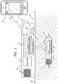
- FIG. 2is a schematic illustration of another system for transdermal detection of a concentration of an analyte in a subject, in accordance with an application of the present invention
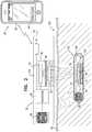
- FIGS. 3A-Care schematic top-view illustrations of several configurations of an implantable unit of the system of FIG. 2 , in accordance with respective applications of the present invention
- FIG. 4is a schematic illustration of yet another system for transdermal detection of a concentration of an analyte in a subject, in accordance with an application of the present invention
- FIG. 5is a schematic top-view illustration of an implantable unit of the system of FIG. 4 , in accordance with an application of the present invention
- FIG. 6is a schematic illustration of a still another system for transdermal detection of a concentration of an analyte in a subject, in accordance with an application of the present invention
- FIG. 7is a schematic top-view illustration of an implantable unit of the system of FIG. 6 , in accordance with an application of the present invention.
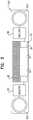
- FIG. 8is a schematic cross-sectional illustration of a portion of the implantable unit of FIG. 7 , in accordance with an application of the present invention.
- FIG. 9is a schematic illustration of an alternative configuration of the system of FIG. 6 , in accordance with an application of the present invention.
- FIGS. 10A-Eare schematic illustrations of configurations of an image sensor, in accordance with respective applications of the present invention.
- FIG. 11is a schematic illustration of another system for transdermal detection of a concentration of an analyte in a subject, in accordance with an application of the present invention.
- FIG. 12is a schematic illustration of yet another system for transdermal detection of a concentration of an analyte in a subject, in accordance with an application of the present invention.
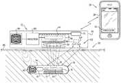
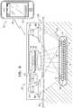
- FIG. 1is a schematic illustration of a system 20 for transdermal detection of a concentration of an analyte in a subject, in accordance with an application of the present invention.
- System 20comprises an implantable unit 30 , which is configured to be implanted in a body of the subject, and an external system 26 , which is physically separate and distinct from implantable unit 30 .
- External system 26comprises an external reading unit 32 and, optionally, an external monitor unit 28 .
- Implantable unit 30comprises fluorescent sensor molecules 40 , each of which comprises a binding site for the analyte, and at least one fluorescent moiety.
- fluorescent sensor molecules 40each of which comprises a binding site for the analyte, and at least one fluorescent moiety.
- fluorescent compoundse.g., Concanavalin-A, fluorescein, and fluorophores derived from various marine fauna, such as GFP and its derivatives.
- the analyte sensingis based on different mechanisms, including, e.g., specific enzymes such as glucose oxidase and glucose dehydrogenase, and bacterial-driven analyte-binding proteins (see, for example, Pickup J C et al., “Fluorescence-based glucose sensors,” Biosensors and Bioelectronics 20 (2005) 2555-2565 (available online Nov. 21, 2004)).
- specific enzymessuch as glucose oxidase and glucose dehydrogenase
- bacterial-driven analyte-binding proteinssee, for example, Pickup J C et al., “Fluorescence-based glucose sensors,” Biosensors and Bioelectronics 20 (2005) 2555-2565 (available online Nov. 21, 2004)
- the analyteis glucose
- the binding siteis for glucose.
- fluorescent sensor molecules 40comprise Fluorescence Resonance Energy Transfer (FRET) sensor molecules.
- the fluorescent moiety of each of fluorescent sensor molecules 40comprises a donor fluorophore and an acceptor fluorophore, as well as an analyte-binding moiety which reversibly changes its shape following specific binding to the target analyte.
- the acceptor fluorophore of the FRET sensor moleculesis selected such that a substantial portion of the light emitted by the acceptor fluorophore is able to penetrate through at least 0.5 mm, e.g., at least 1 mm, such as at least 2 mm of tissue (which typically includes skin 80 ).
- the acceptor fluorophoremay be selected such that a substantial portion (e.g., at least 10%, such as at least 20%, e.g., at least 40%) of the emission spectrum of the acceptor fluorophore is at a wavelength greater than 625 nm, e.g., greater than 650 nm, greater than 675 nm, or greater than 700 nm.
- the emission peak wavelengthcorresponds approximately to this wavelength of the substantial portion of the emission spectrum, such that the emission peak wavelength of the acceptor fluorophore is greater than 600 nm, e.g., greater than 625 nm, greater than 650 nm, greater than 675 nm, or greater than 700 nm.
- the emission peakmay be between 625 nm and 675 nm.
- the systemis configured to excite the FRET sensor molecules with a single excitation frequency, and to measure the resulting emission from the donor and the acceptor at two different frequencies, respectively, as is standard in the FRET art.
- the systemis configured to excite the FRET sensor molecules at two different excitation frequencies, and to measure the resulting emission from the FRET sensor molecules at a single acceptor emission frequency, such as described hereinbelow with reference to FIGS. 1 and 2 .
- the FRET sensor moleculescomprise a yellow fluorophore having substantial emission in the range 500-650 nm, which is suitable for exciting red or far-red fluorophores having an excitation spectrum substantially at the same wavelength range.
- the acceptor fluorophoremay comprise a far-red fluorophore, such as mKate, mKate2, mRuby2, mCardinal, mNeptune1, mNeptune2, or mNeptune2.5, as are known in the art.
- a far-red fluorophoresuch as mKate, mKate2, mRuby2, mCardinal, mNeptune1, mNeptune2, or mNeptune2.5, as are known in the art.
- the donor fluorophorecomprises a yellow fluorophore, such as EYFP, Citrine, tagYFP, mVenus, mClover, mNeon, or mBanana, as are known in the art.
- each of the FRET sensor moleculesis a FRET protein, which comprises (a) a green or yellow fluorescent protein as the donor fluorophore, (b) a red or infrared fluorescent protein as the acceptor fluorophore, with at least 10%, such as at least 20%, of the emission of the acceptor at wavelengths greater than 650 nm, and (c) a glucose binding protein having a dissociation factor for glucose, for example, with a Kd in the range of 2 to 10 mM, enabling sensitive measurement to be taken in the physiological range of glucose concentrations.
- each of fluorescent sensor molecules 40comprises exactly one fluorescent moiety, rather than a FRET molecule.
- each of fluorescent sensor molecules 40comprises exactly two fluorescent moieties.
- implantable unit 30further comprises an implantable-unit light source 42 .
- implantable-unit light source 42is configured to generate light having a first illumination peak wavelength that is greater than 300 nm and less than 600 nm, typically less than 550 nm (e.g., less than 525 nm, such as less than 500 nm, e.g., about 470 nm) and appropriate for excitation of the fluorescent moiety.
- the fluorescent moietyemits fluorescent light having an emission peak wavelength.
- the emission peak wavelengthis between 100 and 500 nm greater than the first illumination peak wavelength, such as between 100 and 250 nm greater than the first illumination peak wavelength.
- the emission peak wavelengthis at least 150 nm greater than the first illumination peak wavelength.
- implantable-unit light source 42comprises a laser; typically, the laser generates the light at substantially a single wavelength, in which case the single wavelength is the first illumination peak wavelength.
- implantable-unit light source 42comprises a light emitting diode (LED); typically, the first illumination peak wavelength of the LED is less than 550 nm, e.g., less than 525 nm, such as less than 500 nm, and the full-width-half-maximum of the LED emission spectrum is typically between 10-40 nm.
- LEDlight emitting diode
- Implantable unit 30typically comprises an enclosure 74 , in which the other components of the implantable unit are disposed. Enclosure 74 has at least one transparent surface 76 , which allows the light generated by fluorescent sensor molecules 40 to exit the implantable unit, and, for applications in which one or more external-unit light sources are provided, for light generated by the external-unit light source(s) to enter the implantable unit.
- implantable unit 30has a volume of no more than 250 mm3, such as less than 100 mm3, e.g., less than 75 mm3.
- packagingis provided, in which implantable unit 30 is stored before implantation, and an external surface of implantable unit 30 is sterile while stored in the packaging.
- External reading unit 32comprises a light sensor 44 , which is configured to sense fluorescent light emitted from the fluorescent moiety.
- external reading unit 32comprises an optical unit 46 , which comprises light sensor 44 and additional optical components, such as at least one filter 48 and/or at least one lens 50 .
- light sensor 44comprises a plurality of sensor elements aligned toward respective portions of the total field of view of optical unit 46 (optionally, though the same or different optical elements), such as an array of sensor elements configured to generate an image of the fluorescent signal, such as described hereinbelow with reference to FIGS. 10A and 10B .
- implantable unit 30comprises light sensor 44 (configuration not shown).
- External system 26further comprises one or more processors, which are configured to: (i) receive, from light sensor 44 , at least one measurement of the fluorescent light emitted from the fluorescent moiety, and (ii) calculate the concentration of the analyte in the subject based on the at least one measurement.
- the one or more processorsare configured to drive implantable-unit light source 42 to generate the light.
- the one or more processorsdrive implantable-unit light source 42 to generate the light substantially without any intervening processing by the implantable unit, i.e., the one or more processors substantially directly drive the implantable-unit light source.
- implantable unit 30comprises more extensive circuitry (such as a processor)
- the one or more processors of external system 26drive the circuitry of the implantable unit (such as by transmitting energy or data to the circuitry) to activate implantable-unit light source 42 to generate the light.
- the implantable unitis configured to periodically generate the light, without triggering and without data communication from the external reading unit.
- external reading unit 32comprises a housing 62 , which contains both light sensor 44 and at least one processor 60 of the one or more processors of external system 26 , such as shown in FIG. 1 .
- Processor 60comprises digital and/or analog components, and typically comprises one or more integrated circuits.
- at least one processor 64 of the one or more of the processorsare located outside of housing 62 of external reading unit 32 , in external monitor unit 28 of external system 26 , which may comprise, for example, a generic computer system, such as a conventional desktop computer, laptop computer, smart phone, tablet computer, or other computer which comprises memory and/or a display.
- External monitor unit 28 unittypically comprises software for carrying out at least a portion of the functions prescribed by the present invention.
- the one or more processorscomprise the at least one processor 60 , which is located in the external reading unit, and the at least one processor 64 that is located outside of the external reading unit in the external monitor unit; for these applications, functions of the one or more processors described herein, and recited in the claims herein, may optionally be distributed among the at least one processor 60 and the at least one processor 64 .
- the at least one processor 60 of the external reading unitmay be configured to receive the measurements of light emitted from the fluorescent moiety
- the at least one processor 64 of external monitor unit 28may be configured to calculate the concentration of the analyte.
- external reading unit 32is in data communication with external monitor unit 28 , such as via one or more wires, wirelessly, and/or over at least one network, e.g., a local network and/or a wide area network, such as the Internet.
- networke.g., a local network and/or a wide area network, such as the Internet.
- system 20is configured to measure the temperature at the position of the implantable unit, and the one or more processors are configured to generate calibration information using the measured temperature, and calculate the concentration of the analyte using the calibration information, such as described hereinbelow with reference to FIGS. 1-12 .
- this calibrationmay substantially enhance the measured accuracy.
- the calibration processmay rely on either prior knowledge of the temperature sensitivity of the sensor protein, or may be based on a learning system that uses data collected during the calibration process and/or during continuous use of the system. Additionally, the system may be configured to perform a measurement only if the sensor temperature is between upper and lower temperature limit values.
- the upper temperature limit valuemay be at least 39 degrees C., e.g., at least 42 degrees C.
- the lower temperature limit valuemay be no more than 32 degrees C., e.g., no more than 28 degrees C.
- implantable unit 30further comprises at least one sensor molecule chamber 70 , in which fluorescent sensor molecules 40 are disposed.
- implantable unit 30further comprises at least one cell chamber 86 , typically adjacent to the at least one sensor molecule chamber 70 .
- the cell chambercontains live cells which are engineered to produce and secrete the fluorescent sensor molecules, for example, as described in WO 2006/006166 to Gross et al., which is incorporated herein by reference.
- implantable unit 30typically further comprises a membrane 72 permeable to nutrients; membrane 72 optionally implements techniques described in WO 2006/006166 to Gross et al.
- implantable unit 30comprises at least one chamber that serves as both sensor molecule chamber 70 and cell chamber 86 ; in other words, the cells secrete the fluorescent sensor molecules into the chamber, and the fluorescent sensor molecules remain in the chamber with the cells.
- fluorescent sensor molecules 40are disposed on a surface of enclosure 74 of implantable unit 30 , rather than in a chamber.
- Implantable unit 30is typically implanted between 0.5 mm and 3 mm below the surface of skin 80 of the subject, for example in the dermis, in fat layers below the dermis, or subcutaneously, typically above muscle.
- external reading unit 32is placed above skin 80 (either in or not in contact with the external surface of the skin).
- External reading unit 32performs optical reading of the light emitted from the implanted unit through the skin, and optionally provides measurement data to external monitor unit 28 , for example by wireless transmission, e.g., using Wi-Fi, Bluetooth, or an IR link.
- the external reading unitmay perform the transmission generally continuously, after each measurement point, and/or by request, in which case data is stored in the external reading unit until requested by the external monitor unit.
- the external reading unitmay be attached to the body, e.g., by adhesive tape; loosely placed on the body, e.g., as a wristwatch; or manually placed on the skin surface for each measurement.
- External system 26may perform calibration of the raw data to enable accurate measurement of the analyte concentration.
- the external monitor unit and/or the external reading unitperform and provide numerical and visual display to the user, and/or provide calibrated data to one or more other systems, such as to a therapeutic system, e.g., a controller of an artificial pancreas system, as known in the art.
- external reading unit 32 and external monitor unit 28are provided in a single, unified unit. This configuration may be particularly useful if measurements are taken on-demand whenever the user brings the external reading unit sufficiently close to the implantable unit.
- implantable unit 30further comprises a wireless energy receiver 82 , which is configured to receive electromagnetic radiation for powering implantable-unit light source 42 .
- Wireless energy receiver 82is electrically coupled to implantable-unit light source 42 .
- the wireless energy receiverwhen it receives the electromagnetic radiation, activates the implantable-unit light source.
- wireless energy receiver 82comprises a coil or an antenna.
- external reading unit 32comprises a wireless energy transmitter 84 , which is configured to transmit the electromagnetic radiation, as is typically done in RFID systems, or, e.g., to transmit power by magnetic induction.
- the wireless energy transmittercomprises a coil or an antenna.
- external reading unit 32transmits power to implantable unit 30 whenever a measurement of the concentration of the analyte is required.
- the one or more processorsare configured to drive implantable-unit light source 42 (and/or the other light sources described herein) to generate the light in pulses.
- Each of the pulsestypically has a duration of at least 0.01 msec, no more than 10 msec, and/or between 0.01 and 10 msec, such as between 1 and 3 msec.
- the implantable unitis configured to illuminate the fluorescent sensor at a constant repetition interval without requiring an external trigger and without data communication from the external reading unit.
- the implantable unitmay comprise a capacitor or battery (not shown) to store energy between the time of charging and a later time in which illumination is performed.
- the external charging of the implantable unitmay suffice in this case for multiple illumination cycles and need not be synchronized with the measurements.
- FIG. 1is a schematic illustration of a system 120 for transdermal detection of a concentration of an analyte in a subject, in accordance with an application of the present invention.
- System 120may implement any of the techniques described herein regarding system 20 , described hereinabove with reference to FIG. 1 .
- Like reference numeralrefer to like elements.
- System 120comprises an implantable unit 130 and an external reading unit 132 .
- fluorescent sensor molecules 40comprise FRET sensor molecules.
- the fluorescent moiety of each of fluorescent sensor molecules 40comprises a donor fluorophore and an acceptor fluorophore, as well as an analyte-binding moiety which reversibly changes its shape following specific binding to the target analyte.
- implantable-unit light source 42is a first implantable-unit light source 42 , which is configured to generate light at the first illumination peak wavelength appropriate for excitation of the donor fluorophore, while minimizing the direct excitation of the acceptor fluorophore.
- the system(system 20 or 120 ) further comprises a second light source 122 , which is configured to generate light at a second illumination peak wavelength appropriate for direct excitation of the acceptor fluorophore, while optionally minimizing the excitation of the donor fluorophore.
- second light source 122comprises a second external-unit light source 124 , which external reading unit 132 comprises, such as shown in FIG. 1 .
- second light source 122comprises a second implantable-unit light source 126 , which implantable unit 130 comprises, such as shown in FIG. 2 .
- implantable unit 130comprises, such as shown in FIG. 2 .
- associated opticsmay be provided, such as a lens 380 , as shown by way of example in FIGS. 6 and 9 , described hereinbelow.
- the one or more processorsare configured to:
- the same collecting optics and light sensoris used to measure the emission from the acceptor fluorophore during the first and the second time periods.
- FRET measurementsare made by illuminating the FRET sensor at a single excitation wavelength, which excites the donor fluorophore, and two simultaneous measurements of fluorescence emitted from both the acceptor and the donor fluorophores.
- the emission peak wavelength of the acceptor fluorophoreis at least 625 nm (in the red or infrared portion of the spectrum), which has better transmission through skin 80 and other tissue than the lower-wavelength emissions from the donor fluorophore in conventional FRET techniques.
- this techniqueunlike convention FRET measurement techniques, enables all signal collection to be done under optimal tissue transmission conditions.
- first light source 42generates light having the first illumination peak wavelength that is greater than 300 nm and less than 550 nm, e.g., less than 525 nm, such as less than 500 nm. Because light in this range of wavelengths is generated by first implantable-unit light source 42 , the light does not need to pass through skin 80 or other tissue. Light in this range of wavelengths does not have good effective penetration through tissue including skin, and thus the light reaching the implant would be highly attenuated if generated by an external light source.
- second light source 122generates light having the second illumination peak wavelength that is greater than 300 nm and less than 650 nm.
- implantable unit 30is configured to drive implantable-unit light source 42 to generate light at the first illumination peak wavelength (appropriate for excitation of the donor fluorophore), in a train of pulses beginning concurrently with receipt of the electromagnetic radiation received by wireless energy receiver 82 , and continuing as long as energy transmission continues.
- implantable-unit light source 42comprises a plurality of light sources 42 , e.g., two or three light sources that generate light at different respective illumination peak wavelengths
- the train of pulsesmay comprise respective trains of pulses generated during respective sequential time periods by the respective light sources.
- Implantable unit 30may be configured to repeat the full train of pulses generated by all of the light sources periodically as long as the energy transmission continues.
- implantable unit 30may be configured to continue the train of pulses generated at the first illumination peak wavelength (appropriate for excitation of the donor fluorophore), such as by first implantable-unit light source 42 , as long as the energy transmission continues. (It may be appropriate to illuminate the donor fluorophore for a greater amount of time than the acceptor fluorophore, because the emission using excitation at the first illumination peak wavelength typically has the smallest signal-to-noise ratio.
- FIGS. 3A-Care schematic top-view illustrations of several configurations of implantable unit 130 , in accordance with respective applications of the present invention.
- Each of fluorescent sensor molecules 40comprises a binding site for the analyte, and is configured to emit fluorescent light having at least one emission peak wavelength in response to excitation light.
- fluorescent sensor molecules 40are fluorescent sensor proteins
- implantable unit 30further comprises the at least one cell chamber 86 , which contains live cells genetically engineered to produce the proteins in situ, such as by continuously expressing the proteins.
- the proteinsmay comprise FRET proteins having FRET complexes.
- the cellssecrete the sensor protein, while for other applications, the cells express but do not secrete a sensor protein.
- implantable unit 30comprises circuitry, which receives power from wireless energy receiver 82 , and drives first and second implantable-unit light sources 42 and 126 to generate light.
- implantable unit 30may be pre-filled with any fluorescent reporter and/or is repeatedly re-filled with a fluorescent reporter, e.g., through a dedicated filling port.
- FIG. 4is a schematic illustration of a system 220 for transdermal detection of a concentration of an analyte in a subject, in accordance with an application of the present invention.
- FIG. 5is a schematic top-view illustration of an implantable unit 230 of system 220 , in accordance with an application of the present invention.
- System 220further comprises an external reading unit 232 .
- System 220may implement any of the techniques described herein regarding system 20 or system 120 , described hereinabove with reference to FIGS. 1 and 2 , respectively.
- Like reference numeralrefer to like elements.
- implantable unit 230comprises at least one first implantable-unit light source 42 and at least one second implantable-unit light source 126 .
- External reading unit 232is configured to drive first and second implantable-unit light sources 42 and 126 to generate the light having the first and the second illumination peak wavelengths, respectively, by transmitting electromagnetic radiation at first and second different RF frequencies, respectively.
- the first illumination peak wavelengthis appropriate for excitation of the donor fluorophore, while minimizing the direct excitation of the acceptor fluorophore
- the second illumination peak wavelengthis appropriate for direct excitation of the acceptor fluorophore, while optionally minimizing the excitation of the donor fluorophore.
- implantable unit 230comprises first and second wireless energy receivers 82 A and 82 B, which are configured to receive the electromagnetic radiation at the first and the second RF frequencies, respectively.
- First and second wireless energy receivers 82 A and 82 Bare electrically coupled to first and second implantable-unit light sources 42 and 126 , respectively, such that the first and second wireless energy receivers, when they receive the electromagnetic radiation, activate the first and second light sources, respectively.
- External reading unit 232thus transmits the electromagnetic radiation at the first RF frequency in order to activate first implantable-unit light source 42 , and at the second RF frequency in order to activate second implantable-unit light source 126 .
- first and second wireless energy receivers 82 A and 82 Bcomprise respective different sized coils and/or different capacitors in order to tune the receivers to their respective RF frequencies.
- This configurationsimplifies implantable unit 230 , because only minimal (possible discrete electronics) or no circuitry is needed to activate the implantable-unit light sources.
- the length and optionally also the power of the illuminationis directly controlled by the energy pulses transmitted by external reading unit 232 , allowing direct control by the one or more processors to compensate for variations in signal strength. Such variations may result, for example, from variations in the concentration of fluorescent sensor molecules 40 from implantable unit to implantable unit or as a function of time.
- external reading unit 232comprises first and second wireless energy transmitters 84 A and 84 B, which are configured to transmit the electromagnetic radiation at the first and the second RF frequencies, respectively, and thus activate first and second implantable-unit light sources 42 and 126 , respectively.
- first and second wireless energy transmitter 84 A and 84 Bcomprise respective different sized coils and/or different capacitors in order to tune the transmitters to their respective RF frequencies, thereby eliminating crosstalk between the transmitters.
- external reading unit 232comprises a wireless energy transmitter that is configured transmit at the first and the second RF frequencies under the control of the one or more processors, for example comprising a single coil.
- FIGS. 6 and 9are schematic illustrations of a system 320 for transdermal detection of a concentration of an analyte in a subject, in accordance with respective applications of the present invention.
- FIG. 7is a schematic top-view illustration of an implantable unit 330 of system 320 in the configuration shown in FIG. 6 , in accordance with an application of the present invention.
- System 320further comprises an external reading unit 332 .
- System 320may implement any of the techniques described herein regarding systems 20 , 120 , or 220 .
- Like reference numeralrefer to like elements.
- each of fluorescent sensor molecules 40comprises (i) a binding site for the analyte, and (ii) at least one fluorescent moiety, which is configured to be excited by light at the illumination peak wavelength.
- Implantable unit 330further comprises an upconversion material 390 , which is disposed in a vicinity of fluorescent sensor molecules 40 .
- the at least one fluorescent moiety of fluorescent sensor molecules 40is configured to be excited by light between a first absorption wavelength and a second absorption wavelength greater than the first absorption wavelength.
- Upconversion material 390is configured to produce emission of light having an emission peak wavelength between the first absorption wavelength and the second absorption wavelength, upon being excited with light having an excitation peak wavelength that is greater than the second absorption wavelength.
- the excitation peak wavelengthis selected for good penetration through tissue including skin 80 , and has better tissue penetration than the emission peak wavelength.
- upconversion material 390comprises nanocrystals.
- Nanocrystalshave been extensively explored for upconversion; for example, see Meng Wang, et al., “Upconversion Nanoparticles: Synthesis, Surface Modification, and Biological Applications,” Nanomedicine 2011 December 7(6):710-729.
- Commercially-available nanocrystals for upconversioncan also be purchased, for example, from Sigma-Aldrich Corporation (St. Louis, Mo.) under the commercial name SunstoneTM, employing a 976 nm excitation wavelength and emission wavelengths ranging between 475 nm and 804 nm. Specifically, 475 nm is a good choice for exciting many green fluorophores that can be used as donors in the biosensor protein.
- the emission light from the upconversion materialin order to be appropriate for excitation of the fluorescent protein, has a peak wavelength within a range of wavelengths determined by the fluorescent protein absorption spectrum.
- the absorption spectrum of the fluorescent proteinhas significant absorption in a wavelength band of about 100-150 nm width, and any light source having significant intensity within this wavelength band is effective in exciting the fluorescent protein.
- upconversion material 390is distributed in alternating areas of upconversion material and fluorescent sensor molecules 40 within a single layer within the at least one sensor molecule chamber 70 , in order to provide close proximity of the upconversion material to the fluorescent sensor molecules.
- upconversion material 390is disposed in a layer adjacent fluorescent sensor molecules 40 , such as above (as shown in FIG. 9 ) or below (arrangement not shown), in order to provide close proximity of the upconversion material to the fluorescent sensor molecules.
- the upconversion materialis mixed with the fluorescent sensor molecules, e.g., by disposing both materials within the same encapsulation material, e.g. hydrogel.
- the second absorption wavelengthis less than 700 nm, and the excitation peak wavelength is greater than 700 nm.
- the excitation peak wavelengthmay be greater than 800 nm, such as greater than 950 nm, e.g., greater than 1000 nm.
- the first absorption wavelengthis greater than 400 nm, and the excitation peak wavelength is less than 1100 nm.
- the second absorption wavelengthis at least 250 nm less than the excitation peak wavelength.
- the second absorption wavelengthis less than 550 nm, and the excitation peak wavelength is greater than 700 nm.
- external reading unit 332typically comprises at least one external-unit light source 322 , which is configured to generate the light having the excitation peak wavelength, which is typically less than 700 nm for these configurations.
- external-unit light source 322is a first external-unit light source 322
- the excitation peak wavelengthis a first excitation peak wavelength
- external reading unit 332further comprises a second external-unit light source 324 , which is configured to generate light having a second excitation peak wavelength that is (a) greater than 700 nm and (b) different from the first excitation peak wavelength.
- the fluorescent moiety of each of fluorescent sensor molecules 40comprises a donor fluorophore and an acceptor fluorophore.
- the light generated by first external-unit light source 322 having the first excitation peak wavelengthis appropriate, after upconversion by upconversion material 390 , for excitation of the donor fluorophore.
- the light generated by second external-unit light source 324 having the second excitation peak wavelengthis appropriate, after upconversion by upconversion material 390 , for direct excitation of the acceptor fluorophore.
- external reading unit 332comprises optics and/or motion systems that are configured to move the beam of the at least one external-unit light source 322 across a wide field of view, e.g., similar to the area of the external reading unit, until the external reading unit identifies an optimal excitation efficiency (which is typically better than that achieved by uniform illumination of the entire field of view).
- external reading unit 132may be configured to indicate to the user a desired movement direction of the external reading unit using user interface 134 , such that the user manually aligns the at least one external-unit light source 322 at the optimal location.
- external reading unit 332comprises multiple external-unit light sources 322 having the same peak excitation wavelength, and one or more processors enabling the selection of one or more external-unit light source enabling better excitation efficiency as compare to operation of all external-unit light sources.
- the one or more processorsare configured to:
- the acceptor fluorophoreis configured to emit fluorescent light having a peak wavelength greater than 625 nm, such as greater than 650 nm.
- upconversion material 390comprises (a) a first upconversion material, which is more efficient at upconverting the light at the first excitation peak wavelength than the light at the second excitation peak wavelength, and (b) a second upconversion material, which is more efficient at upconverting the light at the second excitation peak wavelength than the light at the first excitation peak wavelength.
- the first and the second upconversion materialscomprise respective nanocrystals of different types, e.g., having different sizes, or comprising different materials and/or coatings. The two different nanocrystal types may be used together in order to optimize the upconversion efficiency at the two specific wavelengths of the light sources of the external reading unit.
- implantable unit 330further comprises at least one mirror 392 arranged at a bottom surface of upconversion material 390 .
- the at least one mirror 392reflects the emission light from upconversion material 390 in a generally perpendicular direction toward fluorescent sensor molecules 40 .
- implantable unit 330further comprises a dichroic mirror 394 arranged at a top surface of upconversion material 390 .
- Dichroic mirror 394is configured to be transparent to the light at the excitation peak wavelength (e.g., infrared radiation or specific portions of infrared radiation), while reflecting the light at the emission peak wavelength (e.g., visible light or specific portions of visible light). Dichroic mirror 394 thus allows the light at the excitation peak wavelength (e.g., infrared) to pass into upconversion material 390 , while inhibiting the upconverted light at the emission peak wavelength (e.g., visible light) from escaping in the direction of the dichroic mirror (and light source). As a result, the light at the emission peak wavelength is better utilized towards exciting fluorescent sensor molecules 40 . For applications in which both mirror 392 and dichroic mirror 394 are provided, the mirrors are generally placed on opposite sides of upconversion material 390 , such as shown in FIG. 8 .
- the excitation peak wavelengthe.g., infrared radiation or specific portions of infrared radiation
- the emission peak wavelengthe.g., visible light or specific portions
- each of the fluorescent sensor moleculescomprises exactly one fluorescent moiety.
- each of the fluorescent sensor moleculescomprises exactly two fluorescent moieties.
- light sensor 44comprises an image sensor 398 , i.e., a sensor that senses features of a spatial distribution of photons that impinge on the sensor.
- Image sensor 398comprises a plurality of sensor elements 400 .
- the one or more processorsare configured to use one or more algorithms in order to separate between (a) the fluorescent light emitted from the fluorescent moiety and (b) background (e.g., ambient) light, and to reduce (e.g., remove, typically by subtracting) the contribution of the background light to the detected light signal.
- background lightmay give rise to a background signal that is detected by most or all of sensor elements 400 , regardless of whether the sensor elements detect a significant level of emissions from fluorescent sensor molecules 40 .
- the one or more processorsare configured to compare the signals generated by the different sensor elements 400 to evaluate the background level that is also sensed by those sensor elements that sense emission from fluorescent sensor molecules 40 .
- the one or more processorsare configured to remove this background (generally by subtraction), thereby minimizing the affect of ambient light conditions on the performance of the system.
- the one or more algorithmsutilize prior information regarding the shape (including size), typically in two dimensions (and optionally in one or three dimensions), of one or more regions of implantable unit 130 at which fluorescent sensor molecules 40 are disposed, in order to identify the fluorescent light emitted from the fluorescent moiety.
- the algorithmsmay use a Fourier analysis in case of a repetitive structure or any specific (e.g., matched) filter that enhances the signal because of its known spatial distribution.
- implantable unit 130comprises the at least one sensor molecule chamber 70 , which contains fluorescent sensor molecules 40
- the one or more algorithmsutilize prior information regarding the shape (including size), typically in two dimensions (and optionally in one or three dimensions), of the at least one sensor molecule chamber 70 .
- the one or more algorithmsutilize prior information regarding the shape (including size), typically in two dimensions (and optionally in one or three dimensions), of the regions at which fluorescent sensor molecules 40 are disposed.
- image sensor 398implements techniques described hereinbelow with reference to FIG. 11 .
- the external reading unitcomprises image sensor 398 . It is noted that FIGS. 10A-E , like the other figures, are not drawn to scale.
- the one or more processorsare configured to:
- image sensor 398comprises an equally-spaced two-dimensional array 402 of equally-sized sensor elements 400 arranged in a rectangular grid having at least two sensor elements in each direction, e.g., a CCD or CMOS image sensor.
- the image sensoris configured to generate one or more two-dimensional pixelated transdermal images of light passing from the body through tissue including skin 80 .
- FIG. 10AFor some applications, as shown schematically in FIG. 10B , image sensor 398 comprises an equally-spaced two-dimensional array 402 of equally-sized sensor elements 400 arranged in a rectangular grid having at least two sensor elements in each direction, e.g., a CCD or CMOS image sensor.
- the image sensoris configured to generate one or more two-dimensional pixelated transdermal images of light passing from the body through tissue including skin 80 .
- the image sensoris configured to generate high-resolution images (for example, including at least 1024 ⁇ 1024 pixels), as is known in the art, using, for example, a CCD or CMOS image sensor.
- image sensor 398comprises a smaller number of sensor elements 400 , which are not necessarily arranged as a grid, such that image sensor 398 is configured to generate low-resolution images.
- image sensor 398may comprise no more than 1,024 sensor elements 400 , such as no more than 64 sensor elements, no more than 32 sensor elements, no more than 25 sensor elements, no more than nine sensors elements, or no more than four sensor elements.
- image sensor 398comprises at least three sensor elements 400 , such as at least four or five sensor elements 400 , e.g., at least eight sensor elements 400 .
- each of sensor elements 400has a surface area of at least 1 mm2, such as at least 4 mm2, and/or no more than 100 mm2, such as no more than 50 mm2.
- sensor elements 400typically comprise respective sampling circuitries 404 .
- each of sampling circuitries 404is configured to output a digital or analogue value indicative of an intensity of light sensed by the corresponding sensor element 400 .
- the external reading unitcomprises control electronics 458 , which are configured to simultaneously read sampling circuitries 404 (typically independently, and typically in parallel).
- control electronics 458is shown only in FIG. 10C , and is shown connected to only a subset of the circuitries; in practice, control electronics 458 is connected to all of the circuitries, and typically is additionally provided in the configurations shown in FIGS.
- control electronics 458are configured to sample all of sampling circuitries 404 in no more than 3 msec, such as no more than 2 msec, e.g., no more than 1 msec. For some applications, these quick sampling periods approximately match the duration of illumination of fluorescent sensor molecules 40 . For some applications, sampling circuitries 404 samples each of the sensor elements during the illumination of fluorescent sensor molecules 40 and before and/or after the illumination.
- These techniquesmay thus provide a faster response time than a conventional pixelated image sensor (e.g., a CCD or CMOS image sensor), which allows synchronization of sensing with the illumination pulse, and thus may allow the one or more processors to reject background that is not synchronized with the illumination pulse.
- a conventional pixelated image sensore.g., a CCD or CMOS image sensor
- These techniquesmay also provide increased design flexibility. Thus the system may enjoy the benefit of removing background both in time and in space while keeping the high collection efficiency of the sensor.
- image sensor 398comprises equally-spaced two-dimensional array 402 of equally-sized sensor elements arranged in a rectangular grid having at least two sensor elements in each direction, and the transdermal images comprise two-dimensional pixelated images.
- image sensor 398comprises no more than 32 sensor elements in each direction, e.g., no more than 16 sensor elements in each direction, such as no more than 5 sensor elements in each direction, e.g., 2 ⁇ 2, 3 ⁇ 3, 4 ⁇ 4, or 5 ⁇ 5 sensor elements.
- image sensor 398may comprise an array of 12-30 sensor elements.
- sensor elements 400are (a) arranged to sense light from different respective portions of a total field of view of image sensor 398 , and (b) not arranged as sensor elements of a rectangular grid of sensor elements.
- the field of view of the image sensormay be about 20 ⁇ 20 mm.
- At least two of sensor elements 400have different respective surface shapes and/or different respective surface areas.
- sensor elements 400comprise:
- At least one of the one or more central sensor elements 400 Ahas a first surface shape, and at least one of the two or more peripheral sensor elements 400 B has a second surface shape that is different from the first surface shape.
- the one or more central sensor elements 400 Acomprise exactly one central sensor element 400 A.
- central sensor element 400 Ais polygonal and has more than four sides, e.g., is hexagonal or octagonal.
- central sensor element 400 Ais elliptical, e.g., circular.
- peripheral sensor elements 400 Bare arranged in two or more rings around the one or more central sensor elements 400 A at respective average distances from the one or more central sensor elements 400 A.
- the peripheral sensor average surface areais less than the central sensor total surface area.
- the central sensor total surface areais at least 50% of the total sensors surface area, and/or no more than 35%, e.g., no more than 25%, of the total sensors surface area.
- the use of one or more relatively large central sensor elements 400 Agenerally improves the signal-to-noise ratio, because the signal typically scales with sensor element area, while noise typically scales at a lower power, e.g., the square root of the area. It is therefore advantageous for best signal to noise (SNR) to use only the signal coming from pixels (elements in an array) that detect significant levels of signal and avoid using other elements that are providing mainly background signal. It is therefore of advantage to use a specially designed sensor array that can combine the benefits of both an array and a single sensor element.
- the one or more processorsare configured to use the one or more central sensor elements 400 A to predominantly sense the light emitted by fluorescent sensor molecules 40 , and the two or more peripheral sensor elements 400 B to predominantly sense background light not emitted by fluorescent sensor molecules 40 .
- the one or more processorsare configured to ascertain the one or more emission areas of the transdermal images corresponding to the locations, in one or two dimensions, of the fluorescent sensor molecules by ascertaining that the one or more central sensor elements 400 A sense predominantly fluorescent light emitted by fluorescent sensor molecules 40 (for example, at last 50% of the light sensed by the one or more central sensor elements 400 A is emitted from fluorescent sensor molecules 40 ), and, optionally, to further ascertain that the one or more peripheral sensor elements 400 B sense predominantly background (e.g., ambient) light not emitted by fluorescent sensor molecules 40 (for example, at last 50% of the light sensed by the one or more peripheral sensor elements 400 B is not be emitted from fluorescent sensor molecules 40 ).
- backgrounde.g., ambient
- sensor elements 400may be arranged in a vector along a single spatial axis (configuration not shown).
- the one or more processorsevaluate the background (e.g., ambient) light level using image sensor 398 by:
- external reading unit 132further comprises a user interface 134 , which typically comprises a graphical display, other visual outputs, and/or an audio generator.
- User interface 134may be incorporated into housing 62 of external reading unit 132 , or may be in a separate component in data communication (wireless or wired) with housing 62 of external reading unit 132 .
- the one or more processorsare configured to (a) ascertain, responsively to one or more respective locations of the one or more emission areas of the transdermal images, a desired movement of external reading unit 132 (e.g., of optical unit 46 ) with respect to an external surface of skin 80 , and (b) output, via user interface 134 , an indication of the desired movement.
- a usermoves external reading unit 132 in order to better align the external reading unit with the implantable unit.
- These techniquesare optionally used in combination with the background removal techniques described above; the one or more processors use the background light sensed by the sensor elements not positioned over fluorescent sensor molecules 40 after centering, for correction of the light sensed from the fluorescent sensor molecules 40 , as described above.
- the indication of the desired movementincludes a direction of the desired movement with respect to the external surface of the skin.
- user interface 134is configured to guide the user to position the external reading unit at the most appropriate location, e.g., using crosshairs, arrows, or other visual or audio indicators (e.g., including pitch and/or volume) of the desired location and/or desired motion toward the desired location.
- the most appropriate locationmay be with a center of the field of view of image sensor 398 (e.g., the one or more central sensor elements 400 A) placed over fluorescent sensor molecules 40 .
- the one or more processorsare configured to: (a) ascertain, responsively to one or more respective locations of the one or more emission areas of the transdermal images, a desired change in disposition of the external reading unit with respect to an external surface of the skin, and (b) output, via user interface 134 , an indication of the desired change in disposition.
- the change in dispositionmay be a change in position of external reading unit 132 with respect to the external surface of the skin, and/or a change in orientation (e.g., rotational orientation) of the external reading unit with respect to the external surface of the skin.
- the systemgenerates an output instructing the user to reposition the external reading unit only if the system detects a positioning error beyond a certain limit.
- the one or more processorsare configured to output the indication upon ascertaining, by the one or more processors, that at least a portion of fluorescent sensor molecules 40 does not appear in the transdermal images.
- the one or more processorsare configured to output an indication, via user interface 134 , if the light signal cannot be measured, e.g., after a certain amount of time or number of attempts, and/or when the implantable unit is located to be beyond a certain distance from the center of the field of view of the image sensor.
- image sensor 398comprises at least three sensor elements, which comprise one or more central sensor elements 400 A, which are disposed in central area 406 of image sensor 398 , and two or more peripheral sensor elements 400 B, which are disposed generally surrounding the one or more central sensor elements 400 A.
- the one or more processorsare configured to ascertain the desired movement of external reading unit 132 by ascertaining that a first intensity of light sensed by one or more first ones of the peripheral sensor elements 400 B is greater than a second intensity of light sensed by one or more second ones of the peripheral sensor elements 400 B.
- the one or more processorsare configured to ascertain that the desired movement is in a direction from the one or more central sensor elements 400 A toward the one or more first ones of the peripheral sensor elements 400 B. This is repeated until the intensity of light sensed by all of the peripheral sensor elements 400 B is approximately equal, indicating that the one or more central sensor elements 400 A are approximately centered over fluorescent sensor molecules 40 .
- the one or more central sensor elements 400 Ahave the central sensor total surface area in aggregate, and the two or more peripheral sensor elements 400 B have the peripheral average surface area, which is less than the central sensor total surface area.
- the one or more central sensor elements 400 Acomprise exactly one central sensor element 400 A.
- at least one of one or more central sensor elements 400 Ahas a first surface shape, and at least one of the two or more peripheral sensor elements 400 B has a second surface shape that is different from the first surface shape.
- the background light sensed by the two or more peripheral sensor elements 400 B not after centeringis used for correction of the light sensed by the one or more central sensor elements 400 A from the fluorescent sensor molecules 40 , as described above.
- the one or more processorsare configured to calculate a background intensity of the light at the at least one peak wavelength at the background areas of the transdermal images, and to correct the calculated at least one intensity of light representing the net emission from the fluorescent sensor molecules using the background intensity.
- the one or more processorsare configured to correct the calculated at least one intensity of the light representing the emission from fluorescent sensor molecules 40 by subtracting the background intensity from an intensity of the light in the one or more emission areas of the transdermal images.
- the one or more processorsare configured to use a one- or two-dimensional representation of a spatial distribution of fluorescent sensor molecules 40 in implantable unit 130 as a factor in the analysis of the transdermal images for ascertaining the one or more areas of the transdermal images corresponding to the locations, in one or two dimensions, of fluorescent sensor molecules 40 .
- the one- or two-dimensional representationmay be loaded in a memory of external system 26 (e.g., the external reading unit) before the external reading unit is provided to the user.
- the one or more processorsare configured to analyze the one- or two-dimensional images of the sensed light with reference to the one- or two-dimensional representation in order to find a best fit between the images and the representation, and then to assume that light outside of this best fit is background noise rather than emissions from fluorescent sensor molecules 40 .
- the fluorescent sensor moleculesare distributed within the implantable unit in a repetitive pattern, and/or in a non-uniform spatial distribution.
- fluorescent sensor molecules 40are distributed within the implantable unit such that in one or more (e.g., a plurality of) distinct areas, a different signal intensity is detected as compared to other areas in which the fluorescent sensor molecules are distributed.
- sensor molecule chamber 70 containing the fluorescent sensor moleculesmay have a lesser thickness in distinct areas 136 than in the other areas, or a greater thickness in distinct areas 138 than in other areas.
- implantable unit 130further comprises the at least one sensor molecule chamber 70 , in which fluorescent sensor molecules 40 are disposed.
- the at least one sensor molecule chamber 70comprises (a) a substrate, which defines one or more surfaces, and (b) a membrane. Fluorescent sensor molecules 40 are disposed in the at least one sensor molecule chamber 70 between the membrane and the one or more surfaces of the substrate.
- the one or more surfaceshave an average reflectivity, and one or more sub-areas of the one or more surfaces have a sub-area reflectivity that is greater than the average reflectivity.
- the one or more processorsare configured to use one or more respective locations of one or more areas of the transdermal images corresponding to locations, in one or two dimensions, of the sub-areas in as a factor in the analysis of the transdermal images for ascertaining the locations of the one or more areas of transdermal images corresponding to the locations, in one or two dimensions, of the fluorescent sensor molecules.
- the sub-area reflectivityis at least twice the average reflectivity.
- the sub-areasare distributed within the at least one sensor molecule chamber 70 in a repetitive pattern.
- the one or more processorsare configured to use the known spatial distribution, in one or two dimensions, of the fluorescent sensor molecules in the implantable unit as a factor in the analysis of the transdermal images for ascertaining the one or more areas of location of the implantable unit in the transdermal images corresponding to the locations, in one or two dimensions, of the fluorescent sensor molecules.
- the one or more processorsare configured to, during one or more third time periods non-overlapping with the first time periods described hereinbelow with reference to FIGS. 1-12 : (a) drive the one or more light sources to generate the light having the second illumination peak wavelength, and (b) calculate the concentration of fluorescent sensor molecules 40 , by analyzing a spatial distribution of the fluorescent light in the transdermal images.
- the one or more processorsare configured to, during the one or more third time periods, analyze the distribution of the fluorescent light in the transdermal images by calculating an extent of absorption of the fluorescent light emitted from the acceptor fluorophore as a function of distance from the one or more second light sources.
- the one or more processorsmay be configured to use measurements at different times in order to remove background emissions.
- the one or more processorsmay be configured to evaluate the background signal using one or more measurements taken before and/or after the light source(s) generate light, and subtract such background signal from the measured light, e.g., to measure the signal at several times during generation of light by the light source(s) and to fit the measured values to the known function of the generated light. This technique may be practiced in combination with the background removal techniques described above.
- FIG. 11is a schematic illustration of a system 420 for transdermal detection of a concentration of an analyte in a subject, in accordance with an application of the present invention.
- System 420comprises an implantable unit 30 and an external reading unit 432 , which is physically separate and distinct from implantable unit 30 .
- Implantable unit 30may implement any of the techniques described hereinabove regarding implantable units 30 , 130 , 230 , and/or 330 .
- external reading unit 432may implement any of the techniques described herein regarding external reading units 32 , 132 , 232 , 332 , and/or 532 , described hereinabove with reference to FIGS. 1-9 and/or FIGS. 10A-E .
- External reading unit 432comprises light sensor 44 , which, in this configuration, comprises image sensor 398 , which may implement any of the configurations described hereinabove with reference to FIGS. 10A-E .
- External reading unit 432further comprises at least one fast response sensor element 454 , e.g., a photodiode.
- a beam splitter 452may be provided to share the optical detection path with the image sensor and the at least one fast response sensor element.
- One or more light sourcesmay be provided in external reading unit 432 (such as shown in FIGS. 1, 6 , and/or 9 ), and/or in implantable unit 30 (such as shown in FIGS. 1, 2 , and/or 4 ).
- the light source(s)may share part of the optical path with the collection channel, such as using a beam splitter.
- the image sensor and the fast response sensor elementare aimed at non-identical portions of the total field of view, without using a beam-splitter.
- the non-identical portionsmay either partially overlap one another, or may be entirely non-overlapping with one another.
- the one or more processorsare configured to use image sensor 398 to identify the location of fluorescent sensor molecules 40 (and thus implantable unit 30 ) and guide the user to improve the position of external reading unit 432 with respect to the implantable unit, such as to position the implantable unit in the center of the field of view of the image sensor. For example, such guidance may be provided using the techniques described hereinabove with reference to FIGS. 1-9 and 10A -E.
- the one or more processorsare configured to use image sensor 398 to evaluate the background signal generated by ambient light, such as using the techniques described hereinabove with reference to FIGS. 1-9 and 10A -E.
- External reading unit 432comprises a high-frequency electronic circuit 456 , which samples fast response sensor element 454 , thereby enabling the integration of only the signal that is synchronized with the illumination pulses generated by the light sources, rejecting all ambient light that is collected at different times.
- External reading unit 432may also comprise control electronics 458 , for processing the signal(s) generated by image sensor 398 .
- the one or more processorsmay be configured to:
- FIG. 12is a schematic illustration of a system 520 for transdermal detection of a concentration of an analyte in a subject, in accordance with an application of the present invention.
- system 520may implement the techniques for individually driving the implantable-unit light sources from the external unit described hereinabove with reference to FIG. 4 .
- System 520comprises an implantable unit 530 , and an external reading unit 532 .
- Implantable unit 530comprises three light sources: (a) first implantable-unit light source 42 , which is configured to emit light appropriate for excitation of the donor fluorophore, (b) second implantable-unit light source 126 , which is configured to emit light appropriate for direct excitation of the acceptor fluorophore, (c) a third implantable-unit light source 528 configured to emit light having a peak wavelength appropriate for effective penetration through the tissue (which typically includes skin 80 ), e.g., greater than 650 nm.
- the strength of the signal emitted by third implantable-unit light source 528does not vary based on the level of sensor protein or analyte, and thus may be useful for several functions, such as described below.
- third implantable-unit light source 528is configured to illuminate in the general direction of the external reading unit.
- at least one reflective surface located within the implantable unitmay reflect the light from third implantable-unit light source 528 in the general direction of the external reading unit.
- third implantable-unit light source 528is directed in any general direction, e.g., in the direction of sensor molecule chamber 70 , and light arrives to light sensor 44 of external reading unit 432 via scattering.
- external reading unit 532is configured to activate third implantable-unit light source 528 to operate at third time periods not overlapping the first and second time periods during which the first and the second light sources operate.
- external reading unit 532is configured to operate third implantable-unit light source 528 in order to enable easier alignment of the external reading unit location with respect to the implantable unit, as discussed above regarding embodiments in which the user receives an indication of desired movement of the external reading unit.
- the light generated by third implantable-unit light source 528may also be useful for locating the implantable unit for extraction of the unit from the subject's body.
- the light generated by third implantable-unit light source 528may provide an indication that the circuitry of the implantable unit is functioning properly even when no light can be detected from the acceptor fluorophore.
- the one or more processorsmay obtain additional information, e.g., regarding the amount of active biosensor protein in the implantable unit. By tracking this ratio over a long time, e.g., by comparing the current value to the value immediately following implantation, the one or more processors may alert the user of the need to replace the implantable unit within some time, based on a decline in this ratio. Because the emission when exciting the acceptor fluorophore directly is not dependent on glucose concentration, such a measurement and alert cannot be confounded by current glucose values.
- external reading unit 532is configured to evaluate the transmission through the tissue of the light generated by third implantable-unit light source 528 , and to utilize this information for the calibration of the measurement of the analyte concentration and/or for the alignment process.
- external reading unit 532is configured to operate third implantable-unit light source 528 as a reference in order to evaluate the amount of fluorescent sensor molecules, e.g., fluorescent protein, in the implantable unit and utilize this information as an indication of the sensor unit status, or as an input factor in order to adjust the duration and/or the intensity of the illumination of the first and/or second light sources.
- fluorescent sensor moleculese.g., fluorescent protein
- the implantable unitis configured to use third implantable-unit light source 528 to transmit a signal indicative of a measured temperature at the position of the implantable unit, such as described hereinbelow with reference to FIGS. 1-12 .
- the one or more processorsare configured to change a ratio of the duration or the total energy of the light pulse at the first illumination peak wavelength to the duration or the total energy of the light pulse at the second illumination peak wavelength. Such a change in ratio (which may include repeated changes over time) may be desirable to achieve acceptable signal levels and/or correct for changes (typically decreases) in the concentration of fluorescent sensor molecules 40 in the implantable device over time, typically in configurations in which each of fluorescent sensor molecules 40 comprises (i) a binding site for the analyte, (ii) a donor fluorophore, and (iii) an acceptor fluorophore, such as described hereinabove.
- the one or more processorsare configured to:
- the first operation periodhas a duration of at least one week.
- the one or more processorsare configured to set the ratio to have the second value based on a decrease in signal strength of fluorescent sensor molecules 40 .
- the one or more processorsare configured to set the ratio to have the second value based on a decrease in a concentration of fluorescent sensor molecules 40 .
- the one or more processorsare configured to ascertain the decrease in the concentration of fluorescent sensor molecules 40 .
- light sensor 44comprises an image sensor, which is configured to generate one or more transdermal images of the fluorescent light emitted from the acceptor fluorophore.
- the one or more processorsare configured to, during one or more third time periods non-overlapping with the first time periods: (a) drive the one or more light sources to generate the light at the second illumination peak wavelength, and (b) calculate the concentration of fluorescent sensor molecules 40 , by analyzing a spatial distribution of the fluorescent light in the transdermal images.
- the one or more processorsare configured to, during the one or more third time periods, analyze the distribution of the fluorescent light in the transdermal images by calculating an extent of absorption of the fluorescent light emitted from the acceptor fluorophore as a function of distance from the one or more second light sources.
- the one or more light sourcescomprise one or more first light sources and one or more second light sources.
- the one or more processorsare configured to drive the one or more first light sources to generate the light at the first illumination peak wavelength, and the one or more second light sources to generate the light at the second illumination peak wavelength.
- the implantable unitcomprises the one or more first light sources and the one or more second light sources, such as described hereinabove with reference to FIG. 4 .
- the implantable unitcomprises the one or more first light sources
- the external reading unitcomprises the one or more second light sources.
- each of fluorescent sensor molecules 40comprises (i) a binding site for the analyte, (ii) a donor fluorophore, and (iii) an acceptor fluorophore, such as described hereinabove, the one or more processors are configured to:
- This techniquemay correct for changes (typically decreases) in the concentration of fluorescent sensor molecules 40 in the implantable device over time. For example, a lower concentration of fluorescent sensor molecules 40 under given illumination conditions may result in a lower signal. The system thus increases the illumination energy (e.g., by increasing the intensity and/or pulse length), resulting in a higher signal. This is repeated until the signal is within a predefined band of values.
- This techniquemay thus help maximize the measurement signal-to-noise ratio to enable accurate measurement, such as by using relatively higher excitation energies when the response from the implantable unit is low, e.g., because of a low concentration of fluorescent sensor molecules or a low concentration of the analyte, e.g., glucose.
- This techniquethus provides automatic compensation for low fluorescent sensor molecules 40 concentration, which enables measurement while the concentration is too low for accurate measurement under standard conditions.
- the techniques described hereinabove with reference to FIGS. 1-9 and 10A -Emay optionally be used to remove the background.
- the one or more light sourcescomprise one or more first light sources and one or more second light sources
- the one or more processorsare configured to drive the one or more first light sources to generate the light at the first illumination peak wavelength, and the one or more second light sources to generate the light at the second illumination peak wavelength.
- the implantable unitcomprises the one or more first light sources and the one or more second light sources, such as described hereinabove with reference to FIG. 4 .
- the implantable unitcomprises the one or more first light sources
- the external reading unitcomprises the one or more second light sources.
- the implantable unitis configured to measure the temperature at the position of the implantable unit, and to transmit the measured temperature to the external reading unit, such as for generation of calibration information, as described hereinabove with reference to FIG. 1 .
- the implantable unitmay comprise at least one temperature-sensitive electronic element such that the time delay between the triggering of the illumination by the external reading unit and the actual timing of the illumination pulse depends on implantable unit temperature.
- the triggering of the illuminationin this context may be, for example, the beginning of the charging pulse supplied to the implantable unit, and the timing of the illumination pulse may be measured, for example, from the timing of the peak intensity of the detected light in the sensor.
- the implantable unitmay be configured such that the at least one temperature-sensitive element in the circuitry causes a change in the time between successive light pulses as a function of temperature; such a change can be readily identified by the external reading unit by analyzing the received optical signal.
- the temperature-sensitive elementmay comprise, for example, a thermistor or a temperature sensitive capacitor.
Landscapes
- Health & Medical Sciences (AREA)
- Life Sciences & Earth Sciences (AREA)
- Physics & Mathematics (AREA)
- Pathology (AREA)
- General Health & Medical Sciences (AREA)
- Medical Informatics (AREA)
- Animal Behavior & Ethology (AREA)
- Optics & Photonics (AREA)
- Veterinary Medicine (AREA)
- Public Health (AREA)
- Surgery (AREA)
- Molecular Biology (AREA)
- Heart & Thoracic Surgery (AREA)
- Biomedical Technology (AREA)
- Biophysics (AREA)
- Engineering & Computer Science (AREA)
- Chemical & Material Sciences (AREA)
- Immunology (AREA)
- Spectroscopy & Molecular Physics (AREA)
- General Physics & Mathematics (AREA)
- Nuclear Medicine, Radiotherapy & Molecular Imaging (AREA)
- Biochemistry (AREA)
- Analytical Chemistry (AREA)
- Chemical Kinetics & Catalysis (AREA)
- Emergency Medicine (AREA)
- Investigating, Analyzing Materials By Fluorescence Or Luminescence (AREA)
Abstract
Description
- during one or more first time periods: (a) drive the first implantable-unit light source to generate the light having the first illumination peak wavelength, and (b) receive, from the light sensor, one or more first measurements (typically of the intensity) of the fluorescent light emitted from the acceptor fluorophore. As a result, a significant portion of the signal is related to the FRET effect and is thus sensitive to the concentration of the analyte. Typically, the emission spectrum from the acceptor fluorophore is selected to have good transmission through tissue including skin, and thus the emission peak wavelength is typically in the red or infrared portions of the spectrum;
- during one or more second time periods non-overlapping with the first time periods: (a) drive the second light source to generate the light having the second illumination peak wavelength, appropriate for direct excitation of the acceptor fluorophore, and (b) receive, from the light sensor, one or more second measurements (typically of the intensity) of the fluorescent light emitted from the acceptor fluorophore. These second measurements are thus largely insensitive of the concentration of the analyte. However, these second measurements provide an optimal reference, because they are of the same emission spectrum as the first measurements, and are dependent in the same way as the first measurement on a number of factors, including (a) the concentration of the FRET sensor molecules, (b) transmission of the optical signal through tissue including skin and/or other intervening material, and through the same optical components of the system, and (c) sensor sensitivity; and
- calculate the concentration of the analyte in the subject based on the first and the second measurements, such as by calculating the ratio of the first and the second measurements. Typically, the one or more processors are configured to apply calibration procedures to both the first and the second measurements, including, for example, background subtraction and/or non-linearity correction. For some applications, the one or more processors are configured to calculate the concentration by dividing the first measurements (optionally calibrated) by the second measurements (optionally calibrated). The ratio thus obtained is thus corrected for common factors, including the amount of the FRET sensor molecules in the implantable unit, their distribution, transmission of the full optical path, including tissue (including skin), as well as the response of the collection channel. Differences between the two measurements that relate to the different excitation conditions, e.g., wavelength, optical path, and transmission through the tissue (including skin), are either assumed constant or otherwise calibrated.
- calculate at least one intensity of the light representing emission from the fluorescent sensor molecules, based on distinguishing between (a) one or more emission areas of the transdermal images corresponding to the locations, in one or two dimensions, of the fluorescent sensor molecules, and (b) background areas of the transdermal images, and
- calculate the concentration of the analyte in the subject based on the at least one intensity of the light emitted from the fluorescent sensor molecules.
- (a) fluorescent sensor molecules, each of which comprises (i) a binding site for the analyte, and (ii) at least one fluorescent moiety configured to emit fluorescent light; and
- (b) an implantable-unit light source that is configured to generate light having an illumination peak wavelength appropriate for excitation of the fluorescent moiety; and
- (a) an external reading unit, which comprises a light sensor, which is configured to sense fluorescent light emitted from the fluorescent moiety having an emission peak wavelength, wherein the emission peak wavelength is between 100 and 500 nm greater than the illumination peak wavelength; and
- (b) one or more processors, which are configured to: (1) drive the implantable-unit light source to generate the light, (2) receive, from the light sensor, at least one measurement of the fluorescent light emitted from the fluorescent moiety, and (3) calculate the concentration of the analyte in the subject based on the at least one measurement.
- (a) fluorescent sensor molecules, each of which comprises (i) a binding site for the analyte, and (ii) at least one fluorescent moiety; and
- (b) an implantable-unit light source that is configured to generate light having an illumination peak wavelength that is greater than 300 nm and less than 550 nm and appropriate for excitation of the fluorescent moiety; and
- (a) an external reading unit, which comprises a light sensor, which is configured to sense fluorescent light emitted from the fluorescent moiety; and
- (b) one or more processors, which are configured to: (i) receive, from the light sensor, at least one measurement of the fluorescent light emitted from the fluorescent moiety, and (ii) calculate the concentration of the analyte in the subject based on the at least one measurement.
- (a) fluorescent sensor molecules, each of which comprises (i) a binding site for the analyte, (ii) a donor fluorophore, and (iii) an acceptor fluorophore; and
- (b) a first implantable-unit light source that is configured to generate light having a first illumination peak wavelength appropriate for excitation of the donor fluorophore;
- (a) an external reading unit, which comprises a light sensor, which is configured to sense fluorescent light emitted from the acceptor fluorophore; and
- (b) one or more processors, which are configured to:
- (i) during one or more first time periods: (a) drive the first implantable-unit light source to generate the light having the first illumination peak wavelength, and (b) receive, from the light sensor, one or more first measurements of the fluorescent light emitted from the acceptor fluorophore,
- (ii) during one or more second time periods non-overlapping with the first time periods: (a) drive the second light source to generate the light having the second illumination peak wavelength, and (b) receive, from the light sensor, one or more second measurements of the fluorescent light emitted from the acceptor fluorophore, and
- (iii) calculate the concentration of the analyte in the subject based on the first and the second measurements.
- drive the one or more light sources to (a) during a plurality of first time periods, generate light having a first illumination peak wavelength appropriate for excitation of the donor fluorophore, and (b) during a plurality of second time periods non-overlapping with the first time periods, generate light having a second illumination peak wavelength appropriate for direct excitation of the acceptor fluorophore,
- receive, from the light sensor, respective measurements of the fluorescent light emitted from the acceptor fluorophore during (a) the first time periods and (b) the second time periods,
- calculate the concentration of the analyte in the subject based on the respective measurements,
- during a first operational period that includes one or more of the first time periods and one or more of the second time periods, set a ratio of an aggregate duration of the first time periods to an aggregate duration of the second time periods to have a first value, and
- during a second operational period that is after the first operational period and that includes one or more of the first time periods and one or more of the second time periods, set the ratio to have a second value that is different from the first value.
- drive the one or more light sources to, during a plurality of first time periods alternating with a plurality of second time periods non-overlapping with the first time periods:
- (a) during the first time periods, (i) generate light having a first illumination peak wavelength appropriate for excitation of the donor fluorophore, and (ii) receive, from the light sensor, measurements of first intensities of the fluorescent light emitted from the acceptor fluorophore, and
- (b) during the second time periods, (i) generate light having a second illumination peak wavelength appropriate for direct excitation of the acceptor fluorophore, and (ii) receive, from the light sensor, measurements of second intensities of the fluorescent light emitted from the acceptor fluorophore,
- for each of a plurality of the first and the second time periods, respectively, set a first energy of the light generated having the first illumination peak wavelength, and a second energy of the light generated having the second illumination peak wavelength, so as to regulate, toward a target value, a relationship of values of the first and the second intensities of the sensed fluorescent light, and
- calculate the concentration of the analyte in the subject based in part on the first energy of the generated light having the first illumination peak wavelength and the second energy of the generated light having the second illumination peak wavelength.
- drive the one or more light sources to, during a plurality of first time periods alternating with a plurality of second time periods non-overlapping with the first time periods:
- calculate at least one intensity of the light representing emission from the fluorescent sensor molecules, based on distinguishing between (a) one or more emission areas of the transdermal images corresponding to locations, in one or two dimensions, of the fluorescent sensor molecules, and (b) background areas of the transdermal images, and
- calculate the concentration of the analyte in the subject based on the at least one intensity of the light emitted from the fluorescent sensor molecules.
- ascertain, responsively to one or more respective locations of the one or more emission areas of the transdermal images, a desired movement of the external reading unit with respect to an external surface of the skin, and
- output, via the user interface, an indication of the desired movement.
- one or more central sensor elements, which are disposed in a central area of the image sensor; and
- two or more peripheral sensor elements, which are disposed generally surrounding the one or more central sensor elements, and
- ascertain, responsively to one or more respective locations of the one or more emission areas of the transdermal images, a desired change in disposition of the external reading unit with respect to an external surface of the skin, and
- output, via the user interface, an indication of the desired change in disposition.
- (a) during one or more first time periods: (i) drive the first light source to generate the light having the first excitation peak wavelength, and (ii) receive, from the light sensor, one or more first measurements of the fluorescent light emitted from the acceptor fluorophore,
- (b) during one or more second time periods non-overlapping with the first time periods: (i) drive the second light source to generate the light having the second excitation peak wavelength, and (ii) receive, from the light sensor, one or more second measurements of the fluorescent light emitted from the acceptor fluorophore, and
- (c) calculate the concentration of the analyte in the subject based on the first and the second measurements.
- (a) fluorescent sensor molecules, each of which comprises (i) a binding site for the analyte, and (ii) at least one fluorescent moiety configured to emit fluorescent light; and
- (b) an implantable-unit light source that is configured to generate light having an illumination peak wavelength appropriate for excitation of the fluorescent moiety;
- during one or more first time periods: (a) drive first implantable-
unit light source 42 to generate light having the first illumination peak wavelength, appropriate for the excitation of the donor fluorophore, and (b) receive, fromlight sensor 44, one or more first measurements (typically of the total energy or peak intensity) of the fluorescent light emitted from the acceptor fluorophore, optionally after having passed through the at least onefilter 48. As a result, a significant portion of the signal is related to the FRET effect and is thus sensitive to the concentration of the analyte. Typically, the emission peak wavelength emitted from the acceptor fluorophore is selected to have good transmission throughtissue including skin 80, and thus is typically in the red or infrared portions of the spectrum, e.g., between 650 and 1250 nm. Typically, the at least onefilter 48 is configured to pass light having a wavelength between 650 nm and 800 nm such that the majority of the light emitted by the acceptor fluorophore and transmitted throughskin 80 is able to pass, while other wavelengths, which may contain background light, are blocked by the filter; - during one or more second time periods non-overlapping with the first time periods: (a) drive second
light source 122 to generate the light having the second illumination peak wavelength, appropriate for direct excitation of the acceptor fluorophore, and (b) receive, fromlight sensor 44, one or more second measurements (typically of the total energy or peak intensity) of the fluorescent light emitted from the acceptor fluorophore, optionally after having passed through the at least onefilter 48. These second measurements are thus largely insensitive of the concentration of the analyte. However, these second measurements provide an optimal reference, because they of the same wavelength as the first measurements, and are dependent in the same way as the first measurement on a number of factors, including (a) the concentration of the FRET sensor molecules, (b) transmission of the optical signal throughtissue including skin 80 and/or other intervening material, and through the same optical components of the system, and (c) sensor sensitivity; and - calculate the concentration of the analyte in the subject based on the first and the second measurements, such as by calculating the ratio of the first and the second measurements. Typically, the one or more processors are configured to apply calibration procedures to both the first and the second measurements, including, for example, background subtraction and/or non-linearity correction. For some applications, the one or more processors calculate the concentration by dividing the first measurements (optionally calibrated) by the second measurements (optionally calibrated). The ratio thus obtained is thus corrected for common factors, including the amount of the FRET sensor molecules in the implantable unit, their distribution, transmission of the full optical path, including tissue (including skin80), as well as the response of the collection channel. Differences between the two measurements that relate to the different excitation conditions, e.g., wavelength, optical path, and transmission through the tissue (including skin), are either assumed constant or otherwise calibrated.
- during one or more first time periods: (a) drive first implantable-
- during one or more first time periods: (i) drive first external-
unit light source 322 to generate light having the first excitation peak wavelength, and (ii) receive, fromlight sensor 44, one or more first measurements of the fluorescent light emitted from the acceptor fluorophore, - during one or more second time periods non-overlapping with the first time periods: (i) drive second external-
unit light source 324 to generate light having the second excitation peak wavelength, and (ii) receive, fromlight sensor 44, one or more second measurements of the fluorescent light emitted from the acceptor fluorophore, and - calculate the concentration of the analyte in the subject based on the first and the second measurements.
- during one or more first time periods: (i) drive first external-
- calculate at least one intensity of the light representing emission from
fluorescent sensor molecules 40, based on distinguishing between (a) one or more emission areas of the transdermal images corresponding to the locations, in one or two dimensions, offluorescent sensor molecules 40, and (b) background areas of the transdermal images, e.g., by subtracting the average background intensity from the sensor emission areas, and - calculate the concentration of the analyte in the subject based on the at least one intensity of the light emitted from
fluorescent sensor molecules 40.
- calculate at least one intensity of the light representing emission from
- one or more
central sensor elements 400A, which are disposed in acentral area 406 ofimage sensor 398.Central sensor elements 400A are configured to obtain the signal under the best orientation conditions; and - two or more (e.g., four or more)
peripheral sensor elements 400B, which are disposed generally surroundingcentral sensor elements 400A (in aperipheral area 408 of image sensor398).Peripheral sensor elements 400B are configured to enable removal of background light and/or alignment of the external reading unit.
- one or more
- the one or more
central sensor elements 400A have a central sensor total surface area in aggregate, - the two or more
peripheral sensor elements 400B have a peripheral sensor average surface area, - all of the sensor elements400 (both the one or more
central sensor elements 400A and the two or moreperipheral sensor elements 400B) have a total sensors surface are in aggregate.
- the one or more
- classifying
sensor elements 400 such that some of thesensor elements 400 are classified as sensing predominantly background (e.g., ambient) (e.g., at least 50%) light (“background sensor elements”; these typically correspond to the one or moreperipheral sensor elements 400B) and someother sensor elements 400 are classified as sensing predominantly (e.g., at least 50%) light generated by fluorescent sensor molecules40 (“signal sensor elements”; these typically correspond to the one or morecentral sensor elements 400A), and - based on the values and spatial distribution of the background sensor elements, evaluate a background light level at the position of the signal sensor elements, e.g., by an average over the background sensor elements, or by fitting the background sensor elements by a continuous function and evaluating the value of the function at a central location representing the signal sensor elements.
- classifying
- drive the one or more light sources to provide pulse illumination to
fluorescent sensor molecules 40 inimplantable unit 30; - synchronize the measurements of both
image sensor 398 and the at least one fastresponse sensor element 454 such that the pulse of the light source is included in the integration time of both measurement channels; - evaluate the background (e.g., ambient) light level using
image sensor 398 by: (a) classifying allsensor elements 400 of the image such that some of thesensor elements 400 are classified as containing predominantly background light (e.g., at least 50%, such as at least 80%) (“background sensor elements”) and some other sensor elements are classified as containing predominantly signal/fluorescent light (e.g., at least 50%, such as at least 80%) generated by fluorescent sensor molecules40 (“signal sensor elements”), and (2) based on the values and spatial distribution of the background sensor elements, evaluate a background light level at the position of the signal sensor elements, e.g., by an average over the background sensor elements, or by fitting the background sensor elements by a continuous function and evaluating the value of the function at a central location representing the signal sensor elements; and/or - adjust the background light level for the differences in integration times and sensitivity between the two sets of sensors, and remove the adjusted background light level from the signal generated by the at least one fast response sensor element, as taken at the time of the illumination pulse generated by light source(s).
- drive the one or more light sources to provide pulse illumination to
- drive one or more light sources (external-unit light sources, internal-unit light sources, or a combination of external-unit and internal-unit light sources) to (a) during a plurality of first time periods, generate light having the first illumination peak wavelength appropriate for excitation of the donor fluorophore, and (b) during a plurality of second time periods non-overlapping with the first time periods, generate light having the second illumination peak wavelength appropriate for direct excitation of the acceptor fluorophore; techniques may be used that are described hereinabove with reference to
FIGS. 1 and 2 for calculating the concentration of the analyte; - receive, from
light sensor 44, respective measurements of the fluorescent light emitted from the acceptor fluorophore during (a) the first time periods and (b) the second time periods; techniques may be used that are described hereinabove with reference toFIGS. 1 and 2 for calculating the concentration of the analyte; - calculate the concentration of the analyte in the subject based on the respective measurements; techniques may be used that are described hereinabove with reference to
FIGS. 1 and 2 for calculating the concentration of the analyte; - during a first operational period that includes one or more of the first time periods and one or more of the second time periods, set a ratio of an aggregate duration of the first time periods to an aggregate duration of the second time periods to have a first value; and
- during a second operational period that is after the first operational period and that includes one or more of the first time periods and one or more of the second time periods, set the ratio to have a second value that is different from the first value, such as greater than the first value of the ratio.
- drive one or more light sources (external-unit light sources, internal-unit light sources, or a combination of external-unit and internal-unit light sources) to (a) during a plurality of first time periods, generate light having the first illumination peak wavelength appropriate for excitation of the donor fluorophore, and (b) during a plurality of second time periods non-overlapping with the first time periods, generate light having the second illumination peak wavelength appropriate for direct excitation of the acceptor fluorophore; techniques may be used that are described hereinabove with reference to
- drive the one or more light sources to, during a plurality of first time periods alternating with a plurality of second time periods non-overlapping with the first time periods:
- (a) during the first time periods, (i) generate light having a first illumination peak wavelength appropriate for excitation of the donor fluorophore, and (ii) receive, from the light sensor, measurements of first intensities of the fluorescent light emitted from the acceptor fluorophore, and
- (b) during the second time periods, (i) generate light having a second illumination peak wavelength appropriate for direct excitation of the acceptor fluorophore, and (ii) receive, from the light sensor, measurements of second intensities of the fluorescent light emitted from the acceptor fluorophore,
- for each of a plurality of the first and the second time periods, respectively, set a first energy of the light (i.e., the integral overtime of the intensity of the light) generated having the first illumination peak wavelength, and a second energy of the light generated having the second illumination peak wavelength, so as to regulate, toward a target value, a relationship of values of the first and the second intensities of the sensed fluorescent light; for example, the one or more processors may regulate a ratio of the values, or may regulate a difference between the values (e.g., reduce a difference between the values, and/or minimize a difference between the values), and
- calculate the concentration of the analyte in the subject based in part on the first energy of the generated light having the first illumination peak wavelength and the second energy of the generated light having the second illumination peak wavelength, for example, based in part on a ratio of (a) the first energy of the generated light having the first illumination peak wavelength and (b) the second energy of the generated light having the second illumination peak wavelength.
- U.S. Pat. No. 7,951,357 to Gross et al.;
- US Patent Application Publication 2010/0160749 to Gross et al.;
- US Patent Application Publication 2010/0202966 to Gross et al.;
- US Patent Application Publication 2011/0251471 to Gross et al.;
- US Patent Application Publication 2012/0059232 to Gross et al.;
- US Patent Application Publication 2013/0006069 to Gil et al.;
- PCT Publication WO 2006/006166 to Gross et al.;
- PCT Publication WO 2007/110867 to Gross et al.;
- PCT Publication WO 2010/073249 to Gross et al.;
- PCT Publication WO 2013/001532 to Gil et al.;
- PCT Publication WO 2014/102743 to Brill et al.;
- U.S.
Provisional Patent Application 60/588,211, filed Jul. 14, 2004; - U.S.
Provisional Patent Application 60/658,716, filed Mar. 3, 2005; - U.S.
Provisional Patent Application 60/786,532, filed Mar. 27, 2006; - U.S. Provisional Patent Application 61/746,691, filed Dec. 28, 2012; and
- U.S. Provisional Patent Application 61/944,936, filed Feb. 26, 2014.
Claims (18)
Priority Applications (1)
| Application Number | Priority Date | Filing Date | Title |
|---|---|---|---|
| US15/517,318US10575765B2 (en) | 2014-10-13 | 2015-10-13 | Analyte-sensing device |
Applications Claiming Priority (3)
| Application Number | Priority Date | Filing Date | Title |
|---|---|---|---|
| US201462063211P | 2014-10-13 | 2014-10-13 | |
| US15/517,318US10575765B2 (en) | 2014-10-13 | 2015-10-13 | Analyte-sensing device |
| PCT/IL2015/051022WO2016059635A1 (en) | 2014-10-13 | 2015-10-13 | Analyte-sensing device |
Publications (2)
| Publication Number | Publication Date |
|---|---|
| US20170303838A1 US20170303838A1 (en) | 2017-10-26 |
| US10575765B2true US10575765B2 (en) | 2020-03-03 |
Family
ID=54364417
Family Applications (1)
| Application Number | Title | Priority Date | Filing Date |
|---|---|---|---|
| US15/517,318Expired - Fee RelatedUS10575765B2 (en) | 2014-10-13 | 2015-10-13 | Analyte-sensing device |
Country Status (4)
| Country | Link |
|---|---|
| US (1) | US10575765B2 (en) |
| EP (1) | EP3206567A1 (en) |
| CN (1) | CN106999118B (en) |
| WO (1) | WO2016059635A1 (en) |
Cited By (2)
| Publication number | Priority date | Publication date | Assignee | Title |
|---|---|---|---|---|
| US20220133234A1 (en)* | 2020-10-29 | 2022-05-05 | Cardiac Pacemakers, Inc. | Integrated thermo-photonic chemical sensor |
| US11484232B2 (en) | 2018-01-23 | 2022-11-01 | Dexcom, Inc. | Systems, devices, and methods to compensate for temperature effects on sensors |
Families Citing this family (19)
| Publication number | Priority date | Publication date | Assignee | Title |
|---|---|---|---|---|
| RU2616653C2 (en)* | 2012-06-05 | 2017-04-18 | Хайпермед Имэджинг, Инк. | Methods and device for coaxial image forming with multiple wavelengths |
| CN106999118B (en) | 2014-10-13 | 2020-07-17 | 葡萄糖传感器公司 | Analyte sensing device |
| US10871487B2 (en) | 2016-04-20 | 2020-12-22 | Glusense Ltd. | FRET-based glucose-detection molecules |
| EP3503805B1 (en)* | 2016-08-26 | 2022-05-04 | Cardiac Pacemakers, Inc. | Systems and methods for determining presence of an analyte using an implantable medical device |
| CN112515668A (en)* | 2016-09-21 | 2021-03-19 | 威里利生命科学有限责任公司 | System and method for activating circuitry of an implanted device |
| WO2018083351A1 (en)* | 2016-11-07 | 2018-05-11 | Koninklijke Philips N.V. | Device and method for physiological parameter detection |
| EP3638119A4 (en)* | 2017-06-15 | 2020-11-25 | Senseonics, Incorporated | System and method for measuring an amount of blood and/or clotting in a pocket surrounding an implantable medical device |
| DE102017118038A1 (en)* | 2017-08-08 | 2019-02-14 | Eesy-Innovation Gmbh | DETECTION DEVICE FOR CAPTURING A BLOOD IMAGE PARAMETER |
| CN109864746B (en)* | 2017-12-01 | 2023-09-29 | 心脏起搏器股份公司 | Multimode analyte sensor for medical devices |
| US12035994B2 (en)* | 2018-05-15 | 2024-07-16 | Efferent Labs, Inc. | Implantable devices and methods of use |
| KR102329700B1 (en)* | 2018-11-08 | 2021-11-22 | 주식회사 와이트랙 | Apparatus and method for monitoring glucose based on fluorescence sensor |
| US11389339B2 (en) | 2019-08-16 | 2022-07-19 | Verily Life Sciences Llc | Determining a presence of auto-fluorescent biological substances through an article |
| US12297041B1 (en) | 2019-09-20 | 2025-05-13 | Verily Life Sciences Llc | Smart diaper pail |
| CN115176155A (en) | 2019-10-25 | 2022-10-11 | 塞卡科实验室有限公司 | Indicator compounds, devices including indicator compounds, and methods of making and using the same |
| CN115190969A (en)* | 2020-01-16 | 2022-10-14 | 耶路撒冷希伯来大学伊森姆研究发展有限公司 | Systems and methods for use in FRET microscopy |
| WO2023282968A1 (en)* | 2021-07-06 | 2023-01-12 | Massachusetts Institute Of Technology | Bioelectronic devices to support transplanted cells in vivo for encapsulated cell therapies |
| US12318182B2 (en) | 2022-10-03 | 2025-06-03 | Know Labs, Inc. | Analyte sensors with antenna array |
| US11696698B1 (en)* | 2022-10-03 | 2023-07-11 | Know Labs, Inc. | Analyte sensors with position adjustable transmit and/or receive components |
| WO2024137338A1 (en)* | 2022-12-21 | 2024-06-27 | Stryker Corporation | Systems and methods for ambient light compensation in medical imaging |
Citations (210)
| Publication number | Priority date | Publication date | Assignee | Title |
|---|---|---|---|---|
| US3486506A (en) | 1965-10-13 | 1969-12-30 | Philips Corp | Heart-actuated,spring driven cardiac stimulator |
| US3554199A (en) | 1967-07-24 | 1971-01-12 | Philips Corp | Heart stimulating device |
| US3774243A (en) | 1971-10-20 | 1973-11-27 | D Ng | Implantable power system for an artificial heart |
| US3826265A (en) | 1972-10-05 | 1974-07-30 | Medtronic Inc | Mechanical pulse generator for cardiac pacer |
| US3837339A (en) | 1972-02-03 | 1974-09-24 | Whittaker Corp | Blood glucose level monitoring-alarm system and method therefor |
| US3837922A (en) | 1969-09-12 | 1974-09-24 | Inst Gas Technology | Implantable fuel cell |
| US3861397A (en) | 1972-01-03 | 1975-01-21 | Siemens Ag | Implantable fuel cell |
| US4140963A (en) | 1972-01-03 | 1979-02-20 | Siemens Aktiengesellschaft | Device for measuring sugar concentration |
| GB2024012A (en) | 1978-04-10 | 1980-01-09 | Johnson & Johnson | Oxygen-generating surgical dressing |
| US4344438A (en) | 1978-08-02 | 1982-08-17 | The United States Of America As Represented By The Department Of Health, Education And Welfare | Optical sensor of plasma constituents |
| US4352883A (en) | 1979-03-28 | 1982-10-05 | Damon Corporation | Encapsulation of biological material |
| US4402694A (en) | 1981-07-16 | 1983-09-06 | Biotek, Inc. | Body cavity access device containing a hormone source |
| US4453537A (en) | 1981-08-04 | 1984-06-12 | Spitzer Daniel E | Apparatus for powering a body implant device |
| US4578323A (en) | 1983-10-21 | 1986-03-25 | Corning Glass Works | Fuel cell using quinones to oxidize hydroxylic compounds |
| US4631053A (en) | 1984-03-19 | 1986-12-23 | Taheri Syde A | Oxygenator |
| US4661107A (en) | 1986-07-21 | 1987-04-28 | Fink Irving E | Heart valve |
| US4721677A (en) | 1985-09-18 | 1988-01-26 | Children's Hospital Medical Center | Implantable gas-containing biosensor and method for measuring an analyte such as glucose |
| US4745279A (en) | 1986-01-02 | 1988-05-17 | American Hospital Supply Corporation | Hematocrit measuring apparatus |
| US4801291A (en) | 1987-11-18 | 1989-01-31 | Loori Phillip E | Portable topical hyperbaric apparatus |
| US4953976A (en) | 1989-03-20 | 1990-09-04 | Spectral Sciences, Inc. | Gas species monitor system |
| WO1990015526A1 (en) | 1989-06-13 | 1990-12-27 | Agristar, Inc. | Integument and method for culturing and growing organic material |
| US4981779A (en) | 1986-06-26 | 1991-01-01 | Becton, Dickinson And Company | Apparatus for monitoring glucose |
| WO1991001680A1 (en) | 1989-08-11 | 1991-02-21 | Palti Yoram Prof | System for monitoring and controlling blood glucose |
| US5001054A (en) | 1986-06-26 | 1991-03-19 | Becton, Dickinson And Company | Method for monitoring glucose |
| US5011472A (en) | 1988-09-06 | 1991-04-30 | Brown University Research Foundation | Implantable delivery system for biological factors |
| WO1991009312A1 (en) | 1989-12-14 | 1991-06-27 | Sensor Technologies, Inc. | Method and device for detecting and quantifying glucose in body fluids |
| US5029579A (en) | 1989-01-13 | 1991-07-09 | Ballard Medical Products | Hyperbaric oxygenation apparatus and methods |
| US5089697A (en) | 1989-01-11 | 1992-02-18 | Prohaska Otto J | Fiber optic sensing device including pressure detection and human implantable construction |
| US5116494A (en) | 1989-08-25 | 1992-05-26 | W. R. Grace & Co.-Conn. | Artificial pancreatic perfusion device with temperature sensitive matrix |
| US5143066A (en) | 1990-05-08 | 1992-09-01 | University Of Pittsburgh | Optical fiber sensors for continuous monitoring of biochemicals and related method |
| WO1992019195A1 (en) | 1991-04-25 | 1992-11-12 | Brown University Research Foundation | Implantable biocompatible immunoisolatory vehicle for delivery of selected therapeutic products |
| US5209231A (en) | 1990-11-02 | 1993-05-11 | University Of Connecticut | Optical glucose sensor apparatus and method |
| US5246867A (en) | 1992-01-17 | 1993-09-21 | University Of Maryland At Baltimore | Determination and quantification of saccharides by luminescence lifetimes and energy transfer |
| US5262055A (en) | 1992-10-19 | 1993-11-16 | The University Of Utah | Implantable and refillable biohybrid artificial pancreas |
| WO1994000602A1 (en) | 1992-06-29 | 1994-01-06 | Sensor Technologies, Inc. | Method and device for detecting and quantifying substances in body fluids |
| US5336209A (en) | 1990-04-06 | 1994-08-09 | Porzilli Louis B | Multi-function wound protection bandage and medicant delivery system with simultaneous variable oxygenation |
| WO1994020076A1 (en) | 1993-03-01 | 1994-09-15 | Giampapa Vincent C | Subcutaneous implantable multiple agent delivery system |
| US5372135A (en) | 1991-12-31 | 1994-12-13 | Vivascan Corporation | Blood constituent determination based on differential spectral analysis |
| US5373855A (en) | 1990-07-04 | 1994-12-20 | Avl Medical Instruments Ag | Two-channel needle for withdrawing body fluids |
| US5381075A (en) | 1992-03-20 | 1995-01-10 | Unisyn | Method and apparatus for driving a flashing light systems using substantially square power pulses |
| US5387522A (en) | 1984-06-01 | 1995-02-07 | Schering Corporation | Apparatus having a biphasic spray head for entrapping biological material in a hydrophilic gel |
| US5407685A (en) | 1986-02-06 | 1995-04-18 | Steris Corporation | Controlled oxygen/anti-microbial release films |
| US5427935A (en) | 1987-07-24 | 1995-06-27 | The Regents Of The University Of Michigan | Hybrid membrane bead and process for encapsulating materials in semi-permeable hybrid membranes |
| US5431694A (en) | 1992-08-18 | 1995-07-11 | Snaper; Alvin A. | Bio-operable power source |
| US5443504A (en) | 1991-09-30 | 1995-08-22 | Hill; John D. | Basic skeletal muscle energy conversion system |
| WO1996000106A1 (en) | 1994-06-27 | 1996-01-04 | Cb-Carmel Biotechnology, Ltd. | Inplantable drug delivery pump |
| US5512474A (en) | 1992-05-29 | 1996-04-30 | Bsi Corporation | Cell culture support containing a cell adhesion factor and a positively-charged molecule |
| US5529066A (en) | 1994-06-27 | 1996-06-25 | Cb-Carmel Biotechnology Ltd. | Implantable capsule for enhancing cell electric signals |
| US5545191A (en) | 1994-05-06 | 1996-08-13 | Alfred E. Mann Foundation For Scientific Research | Method for optimally positioning and securing the external unit of a transcutaneous transducer of the skin of a living body |
| US5578022A (en) | 1995-04-12 | 1996-11-26 | Scherson; Daniel A. | Oxygen producing bandage and method |
| US5614378A (en) | 1990-06-28 | 1997-03-25 | The Regents Of The University Of Michigan | Photobioreactors and closed ecological life support systems and artifificial lungs containing the same |
| US5626134A (en) | 1994-04-21 | 1997-05-06 | Zuckerman; Ralph | Method and apparatus for the measurement of analyte concentration levels by the steady-state determination of fluorescence lifetime |
| US5660940A (en) | 1993-12-20 | 1997-08-26 | Sufucell Ab | Method for producing electric energy in a biofuel-powered fuel cell |
| US5662625A (en) | 1996-05-06 | 1997-09-02 | Gwr Medical, L.L.P. | Pressure controllable hyperbaric device |
| US5702444A (en) | 1995-09-11 | 1997-12-30 | Struthers, Mehta And Maxwell | Implantable artificial endocrine pancreas |
| US5713888A (en) | 1990-10-31 | 1998-02-03 | Baxter International, Inc. | Tissue implant systems |
| US5741334A (en) | 1995-06-07 | 1998-04-21 | Circe Biomedical, Inc. | Artificial pancreatic perfusion device |
| US5770454A (en) | 1994-05-19 | 1998-06-23 | Boehringer Mannheim Gmbh | Method and aparatus for determining an analyte in a biological sample |
| US5788682A (en) | 1995-04-28 | 1998-08-04 | Maget; Henri J.R. | Apparatus and method for controlling oxygen concentration in the vicinity of a wound |
| US5792090A (en) | 1995-06-15 | 1998-08-11 | Ladin; Daniel | Oxygen generating wound dressing |
| US5834005A (en) | 1992-02-24 | 1998-11-10 | Encelle, Inc. | Bioartificial devices and cellular matrices therefor |
| US5833603A (en) | 1996-03-13 | 1998-11-10 | Lipomatrix, Inc. | Implantable biosensing transponder |
| WO1998054294A1 (en) | 1997-05-30 | 1998-12-03 | Board Of Trustees, Leland Stanford, Jr. University | Microelectronic biosensor and method of monitoring cultured cells |
| WO1998055869A1 (en) | 1997-06-04 | 1998-12-10 | Sensor Technologies, Inc. | Method and device for detecting or quantifying carbohydrate containing compounds |
| US5855613A (en) | 1995-10-13 | 1999-01-05 | Islet Sheet Medical, Inc. | Retrievable bioartificial implants having dimensions allowing rapid diffusion of oxygen and rapid biological response to physiological change |
| US5879709A (en) | 1991-11-25 | 1999-03-09 | Vivorx, Inc. | Method of treating patients with diabetes |
| US5902745A (en) | 1995-09-22 | 1999-05-11 | Gore Hybrid Technologies, Inc. | Cell encapsulation device |
| US5912005A (en) | 1994-04-15 | 1999-06-15 | Biohybrid Technologies, Inc. | Methods of use of uncoated gel particles |
| US5998204A (en) | 1997-03-14 | 1999-12-07 | The Regents Of The University Of California | Fluorescent protein sensors for detection of analytes |
| US6000403A (en) | 1995-08-02 | 1999-12-14 | Cantwell; Evelyna Dyson | Oxygen bandage |
| US6049728A (en) | 1997-11-25 | 2000-04-11 | Trw Inc. | Method and apparatus for noninvasive measurement of blood glucose by photoacoustics |
| US6049727A (en) | 1996-07-08 | 2000-04-11 | Animas Corporation | Implantable sensor and system for in vivo measurement and control of fluid constituent levels |
| US6061582A (en) | 1994-02-14 | 2000-05-09 | University Of Iowa Research Foundation | Method and apparatus for non-invasive determination of physiological chemicals, particularly glucose |
| US6148232A (en) | 1998-11-09 | 2000-11-14 | Elecsys Ltd. | Transdermal drug delivery and analyte extraction |
| US6163714A (en) | 1998-07-03 | 2000-12-19 | Torsana Diabetes Diagnostics A/S | Optical sensor for in situ measurement of analytes |
| WO2000078920A1 (en) | 1999-06-21 | 2000-12-28 | The General Hospital Corporation | Methods and devices for cell culturing and organ assist systems |
| US6179804B1 (en) | 1999-08-18 | 2001-01-30 | Oxypatch, Llc | Treatment apparatus for wounds |
| US6187043B1 (en) | 1987-12-22 | 2001-02-13 | Walter J. Ledergerber | Implantable prosthetic device |
| US6188477B1 (en) | 1998-05-04 | 2001-02-13 | Cornell Research Foundation, Inc. | Optical polarization sensing apparatus and method |
| US6197534B1 (en) | 1998-07-17 | 2001-03-06 | Joseph R. Lakowicz | Engineered proteins for analyte sensing |
| US6254601B1 (en) | 1998-12-08 | 2001-07-03 | Hysterx, Inc. | Methods for occlusion of the uterine arteries |
| US6256522B1 (en) | 1992-11-23 | 2001-07-03 | University Of Pittsburgh Of The Commonwealth System Of Higher Education | Sensors for continuous monitoring of biochemicals and related method |
| WO2001050983A1 (en) | 2000-01-12 | 2001-07-19 | Beta O 2 Technologies Ltd | Implantable device |
| US6268161B1 (en) | 1997-09-30 | 2001-07-31 | M-Biotech, Inc. | Biosensor |
| US6294281B1 (en) | 1998-06-17 | 2001-09-25 | Therasense, Inc. | Biological fuel cell and method |
| US6330464B1 (en) | 1998-08-26 | 2001-12-11 | Sensors For Medicine & Science | Optical-based sensing devices |
| US20020016535A1 (en) | 2000-01-28 | 2002-02-07 | Martin W. Blake | Subcutaneous glucose measurement device |
| US6349234B2 (en) | 1998-06-12 | 2002-02-19 | Intermedics Inc. | Implantable device with optical telemetry |
| US20020038083A1 (en) | 2000-07-24 | 2002-03-28 | Richard Houben | Cell-based biosensors suitable for implantable medical device applications |
| US6368592B1 (en) | 1998-07-17 | 2002-04-09 | Massachusetts Institute Of Technology | Method of delivering oxygen to cells by electrolyzing water |
| US6383478B1 (en) | 1999-04-22 | 2002-05-07 | Vanderbilt University | Polymeric encapsulation system promoting angiogenesis |
| US6400974B1 (en) | 2000-06-29 | 2002-06-04 | Sensors For Medicine And Science, Inc. | Implanted sensor processing system and method for processing implanted sensor output |
| US20020072657A1 (en) | 1999-10-28 | 2002-06-13 | Gerald G. Bousquet | Method and apparatus for analyte detection using intradermally implanted skin port |
| US20020120186A1 (en) | 2001-01-08 | 2002-08-29 | Keimel John G. | Sensor system |
| US6471687B2 (en) | 1995-06-07 | 2002-10-29 | Gore Enterprise Holdings, Inc. | Implantable containment apparatus for a therapeutical device |
| US6485703B1 (en) | 1998-07-31 | 2002-11-26 | The Texas A&M University System | Compositions and methods for analyte detection |
| US20020193672A1 (en) | 1995-11-22 | 2002-12-19 | Walsh Joseph C. | Long wave fluorophore sensor compounds and other fluorescent sensor compounds in polymers |
| WO2003011445A2 (en) | 2001-08-01 | 2003-02-13 | Monzyk Bruce F | Photolytic cell for providing physiological gas exchange |
| US6521446B2 (en) | 1997-12-31 | 2003-02-18 | Duke University | Biosensor |
| US20030050622A1 (en) | 2001-09-11 | 2003-03-13 | The University Of Michigan | Device and method to maintain vascularization near implant |
| WO2003025220A2 (en) | 2001-09-18 | 2003-03-27 | Carnegie Institution Of Washington | Fusion proteins useful for detecting analytes |
| US6556867B1 (en) | 1999-10-07 | 2003-04-29 | General Electric Company | Apparatus and method to power a medical device using stored mechanical power |
| US6577393B1 (en) | 1998-06-12 | 2003-06-10 | Glukomeditech Ab | Polarimetric method for determining the (main) vibration plane of polarized light to about 0.1m° and miniaturized device for its implemention |
| US20030113302A1 (en) | 2001-08-31 | 2003-06-19 | Elena Revazova | Use of recipient endothelial cells for enhanced vascularization of tissue and tissue-engineered construct transplants |
| US6584335B1 (en) | 1997-08-09 | 2003-06-24 | Roche Diagnostics Gmbh | Analytical device for in vivo analysis in the body of a patient |
| US20030117629A1 (en) | 1999-10-08 | 2003-06-26 | Rio Grande Medical Technologies, Inc. | Interferometer spectrometer with reduced alignment sensitivity |
| WO2003051623A2 (en) | 2001-11-08 | 2003-06-26 | Salzburg Trading Corporation | Diffusion bonded metal laminate |
| US6587704B1 (en) | 1999-06-16 | 2003-07-01 | Orsense Ltd. | Method for non-invasive optical measurements of blood parameters |
| US20030134346A1 (en) | 2002-01-04 | 2003-07-17 | Amiss Terry J. | Binding protein as biosensors |
| US6625479B1 (en) | 1998-07-03 | 2003-09-23 | Torsana Diabetes Diagnostics A/S | Optical sensor for in situ measurement of analytes |
| US6630154B1 (en) | 1999-01-04 | 2003-10-07 | Biomm, Inc. | Polymer formulations containing perfluorinated compounds for the engineering of cells and tissues for transplantation that improves cell metabolism and survival, and methods for making same |
| US6650919B2 (en) | 2000-05-03 | 2003-11-18 | Cornell Research Foundation, Inc. | Enhanced biologically based chronotropic biosensing |
| US20030227681A1 (en) | 2002-06-11 | 2003-12-11 | Marc Currie | Multipass optical retroreflector and method of using |
| US20030232370A1 (en) | 2002-04-22 | 2003-12-18 | Trifiro Mark A. | Glucose sensor and uses thereof |
| US6671527B2 (en) | 2000-10-13 | 2003-12-30 | Precisense A/S | Optical sensor for in situ measurement of analytes |
| US6673596B1 (en) | 1997-11-25 | 2004-01-06 | Ut-Battelle, Llc | In vivo biosensor apparatus and method of use |
| WO2004028358A1 (en) | 2002-09-24 | 2004-04-08 | Pendragon Medical Ltd. | Device for the measurement of glucose concentrations |
| US20040091757A1 (en) | 2001-12-31 | 2004-05-13 | Xingwu Wang | Implantable fuel cell |
| US20040097788A1 (en) | 2002-05-30 | 2004-05-20 | Mourlas Nicholas J. | Apparatus and methods for coronary sinus access |
| USRE38525E1 (en) | 1998-07-03 | 2004-06-08 | Torsana Diabetes Diagnostics A/S | Optical sensor for in situ measurement of analytes |
| US20040109302A1 (en) | 2001-02-28 | 2004-06-10 | Kenji Yoneda | Method of cultivating plant and illuminator for cultivating plant |
| US20040111018A1 (en) | 2002-12-09 | 2004-06-10 | Research and Education Institute | Conjunctival monitor |
| WO2004051774A2 (en) | 2002-11-27 | 2004-06-17 | St. Louis University | Enzyme immobilization for use in biofuel cells and sensors |
| US6767342B1 (en) | 2001-04-23 | 2004-07-27 | Evelyna D. Cantwell | Oxygen bandage system |
| US20040199059A1 (en) | 2003-04-04 | 2004-10-07 | Dexcom, Inc. | Optimized sensor geometry for an implantable glucose sensor |
| US20040199062A1 (en)* | 2001-07-10 | 2004-10-07 | Bo Petersson | Optical sensor containing particles for in situ measurement of analytes |
| US6804544B2 (en) | 1995-11-22 | 2004-10-12 | Minimed, Inc. | Detection of biological molecules using chemical amplification and optical sensors |
| WO2004089465A1 (en) | 2003-04-14 | 2004-10-21 | Remon Medical Technologies Ltd | Acoustic telemetry apparatus for intrabody communications |
| US6821107B1 (en) | 1999-10-29 | 2004-11-23 | Secretary Of Agency Of Industrial Science And Technology | Method of forming a structure having multiple cell layers |
| US20040259270A1 (en) | 2003-06-19 | 2004-12-23 | Wolf David E. | System, device and method for exciting a sensor and detecting analyte |
| WO2005002467A2 (en) | 2003-07-07 | 2005-01-13 | Brainsgate Ltd. | Stimulation arena |
| US6846288B2 (en) | 2000-08-24 | 2005-01-25 | Glucon Inc. | Photoacoustic assay and imaging system |
| US20050027332A1 (en) | 2003-07-30 | 2005-02-03 | Zohar Avrahami | Implanted autonomic energy source |
| US20050025680A1 (en) | 2002-02-20 | 2005-02-03 | Monzyk Bruce F | Photolytic cell for providing physiological gas exchange |
| US20050054100A1 (en) | 2003-09-08 | 2005-03-10 | Rennard Stephen I. | Methods for fibroblast differentiation |
| WO2005033659A2 (en) | 2003-09-29 | 2005-04-14 | Pelikan Technologies, Inc. | Method and apparatus for an improved sample capture device |
| US20050085868A1 (en) | 2003-10-15 | 2005-04-21 | Tehrani Amir J. | Breathing therapy device and method |
| US20050095174A1 (en) | 2003-10-31 | 2005-05-05 | Wolf David E. | Semipermeable sensors for detecting analyte |
| US20050096516A1 (en) | 2003-10-30 | 2005-05-05 | Orhan Soykan | Optical detector of organic analyte |
| US20050113852A1 (en) | 2003-11-20 | 2005-05-26 | Vascular Control Systems, Inc. | Uterine artery occlusion device with cervical receptacle |
| US20050118726A1 (en) | 2002-08-26 | 2005-06-02 | Schultz Jerome S. | System and method for detecting bioanalytes and method for producing a bioanalyte sensor |
| WO2005053523A1 (en) | 2003-12-02 | 2005-06-16 | Solianis Holding Ag | A device and method for measuring a property of living tissue |
| US20050136092A1 (en) | 2000-01-01 | 2005-06-23 | Beta-O2 Technologies Ltd. | Implantable device |
| US20050211572A1 (en) | 1999-09-20 | 2005-09-29 | Buck Harvey B | Electrochemical sensor and method for continuous analyte monitoring |
| US20050221072A1 (en) | 2003-04-17 | 2005-10-06 | Nanosys, Inc. | Medical device applications of nanostructured surfaces |
| US20050221276A1 (en) | 2002-10-11 | 2005-10-06 | Case Western Reserve University | Sensor system |
| US20050267326A1 (en) | 2001-10-02 | 2005-12-01 | Alfred E. Mann Institute For Biomedical Eng. At The University Of Southern California | Percutaneous chemical sensor based on fluorescence resonant energy transfer (FRET) |
| US20060000479A9 (en) | 2000-04-21 | 2006-01-05 | Fred Burbank | Methods for minimally-invasive, non-permanent occlusion of a uterine artery |
| WO2006006166A2 (en) | 2004-07-14 | 2006-01-19 | Glusense, Ltd. | Implantable power sources and sensors |
| US20060063140A1 (en) | 1998-10-13 | 2006-03-23 | Yissum Research Development Company Of The Hebrew University Of Jerusalem | Hydrocolloid coating of a single cell or embryo |
| WO2006044612A2 (en) | 2004-10-14 | 2006-04-27 | Carnegie Institution Of Washington | Development of sensitive fret sensors and methods of using the same |
| US7068867B2 (en) | 2003-01-02 | 2006-06-27 | Glucon Medical Ltd | Ultrasonic position indicator |
| US20060184206A1 (en) | 2005-02-15 | 2006-08-17 | Baker Rex M Iii | Implantable generating system |
| WO2006097933A2 (en) | 2005-03-17 | 2006-09-21 | Glucon Inc. | Method for monitoring changes in blood glucose level |
| US20060241365A1 (en) | 2003-12-18 | 2006-10-26 | Elliot Botvinick | Implantable Biosensor and Methods of Use Thereof |
| US20070004974A1 (en) | 2003-12-29 | 2007-01-04 | Glucon, Inc. | Glucometer comprising an implantable light source |
| US7184810B2 (en) | 2002-09-04 | 2007-02-27 | Solianis Holding Ag | Method and a device for measuring glucose |
| US20070066877A1 (en) | 2005-04-04 | 2007-03-22 | Arnold Mark A | Reagentless optical analyte detection system |
| US20070190038A1 (en) | 2002-03-04 | 2007-08-16 | New X-National Technology K.K. | Closed cell culture system |
| US7259906B1 (en) | 2002-09-03 | 2007-08-21 | Cheetah Omni, Llc | System and method for voice control of medical devices |
| WO2007110867A2 (en) | 2006-03-28 | 2007-10-04 | Glusense Ltd. | Implantable sensor |
| WO2008018079A2 (en) | 2006-08-09 | 2008-02-14 | Mellitor Ltd | Polarimeter based on a mach-zehnder interferometer |
| US20080086042A1 (en) | 2006-10-04 | 2008-04-10 | Dexcom, Inc. | Analyte sensor |
| WO2008062417A2 (en) | 2006-11-22 | 2008-05-29 | Beta O2 Technologies Ltd. | Protecting algae from body fluids |
| WO2008065660A2 (en) | 2006-11-28 | 2008-06-05 | Beta O2 Technologies Ltd. | Oxygen supply for cell transplant and vascularization |
| WO2008079997A2 (en) | 2006-12-22 | 2008-07-03 | Medtronic, Inc. | Implantable device, angiogenesis mechanism and methods |
| US20080166329A1 (en) | 2005-10-24 | 2008-07-10 | Hsing-Wen Sung | Medical device and methods for living cell injection |
| US20080188722A1 (en) | 2007-02-06 | 2008-08-07 | Markle David R | Optical determination of ph and glucose |
| US20080262567A1 (en) | 2004-07-15 | 2008-10-23 | Zohar Avrahami | Implanted energy source |
| US20080287776A1 (en) | 2007-05-16 | 2008-11-20 | Yaron Ephrath | Gastric band with position sensing |
| US7489402B2 (en) | 2006-12-04 | 2009-02-10 | Finesse Solutions, Llc | Optical collection geometries for phase fluorimetry |
| WO2009031154A2 (en) | 2007-09-07 | 2009-03-12 | Beta O2 Technologies Ltd. | Air gap for supporting cells |
| WO2009039207A1 (en) | 2007-09-19 | 2009-03-26 | Oncofluor, Inc. | Method for imaging and treating organs and tissues |
| US20090178459A1 (en) | 2003-08-01 | 2009-07-16 | Dexcom, Inc. | Analyte sensor |
| US20090192493A1 (en) | 2008-01-03 | 2009-07-30 | University Of Southern California | Implantable drug-delivery devices, and apparatus and methods for refilling the devices |
| US20090287060A1 (en) | 2008-05-14 | 2009-11-19 | Physcient, Inc. | Methods and devices to decrease tissue trauma during surgery |
| WO2009140757A1 (en) | 2008-05-20 | 2009-11-26 | University Health Network | Device and method for fluorescence-based imaging and monitoring |
| US20100015709A1 (en) | 2006-02-10 | 2010-01-21 | Trustees Of The University Of Pennsylvania | Regulating Stem Cell Differentiation By Controlling 2D and 3D Matrix Elasticity |
| WO2010032242A1 (en) | 2008-09-17 | 2010-03-25 | Beta O2 Technologies Ltd. | Optimization of alginate encapsulation of islets for transplantation |
| WO2010061387A2 (en) | 2008-11-26 | 2010-06-03 | Beta O2 Technologies Ltd. | Apparatus for transportation of oxygen to implanted cells |
| US20100145317A1 (en) | 2007-04-19 | 2010-06-10 | Morris Laster | Device system and method for monitoring and controlling blood analyte levels |
| EP2196795A1 (en) | 2007-08-30 | 2010-06-16 | Mitsui Engineering & Shipbuilding Co., Ltd. | Fret detection method and device |
| US20100160749A1 (en) | 2008-12-24 | 2010-06-24 | Glusense Ltd. | Implantable optical glucose sensing |
| WO2010073249A1 (en) | 2008-12-24 | 2010-07-01 | Glusense, Ltd. | Implantable optical glucose sensing |
| WO2010089739A2 (en) | 2009-02-09 | 2010-08-12 | Nano-Retina, Inc. | Retinal prosthesis |
| US20100312483A1 (en)* | 2007-02-06 | 2010-12-09 | Glumetrics, Inc. | Algorithms for calibrating an analyte sensor |
| US7863038B2 (en) | 2002-03-29 | 2011-01-04 | Board Of Regents, The University Of Texas System | Implantable biosensor from stratified nanostructured membranes |
| WO2011072401A1 (en) | 2009-12-18 | 2011-06-23 | University Health Network | System and method for sub-surface fluorescence imaging |
| US20110190679A1 (en) | 2008-08-15 | 2011-08-04 | Innovative Biotherapies, Inc. | Extracorporeal cell-based therapeutic device and delivery system |
| US8088595B2 (en) | 2005-09-28 | 2012-01-03 | The Texas A&M University System | Method for glucose monitoring using fluorescence quenching |
| AU2011253785A1 (en) | 2006-02-07 | 2012-01-12 | Spinalcyte, Llc | Methods and compositions for repair of cartilage using an in vivo bioreactor |
| US20120290043A1 (en) | 2011-05-12 | 2012-11-15 | Rainbow Medical Ltd. | Implanted energy source |
| WO2013001532A1 (en) | 2011-06-30 | 2013-01-03 | Glusense, Ltd. | Implantable optical glucose sensing |
| US20130116664A1 (en) | 2011-03-14 | 2013-05-09 | Minipumps, Llc | Implantable drug pumps and refill devices therefor |
| WO2013155553A1 (en) | 2012-04-16 | 2013-10-24 | Commonwealth Scientific And Industrial Research Organisation | Methods and systems for detecting an analyte or classifying a sample |
| US20130331667A1 (en) | 2012-03-29 | 2013-12-12 | Senseonics, Incorporated | Purification of glucose concentration signal in an implantable fluorescence based glucose sensor |
| US20140018644A1 (en) | 2012-03-29 | 2014-01-16 | Senseonics, Incorporated | Purification of glucose concentration signal in an implantable fluorescence based glucose sensor |
| US20140088383A1 (en) | 2012-09-14 | 2014-03-27 | Senseonics, Incorporated | Integrated catalytic protection of oxidation sensitive materials |
| US8700115B2 (en) | 2009-11-04 | 2014-04-15 | Glumetrics, Inc. | Optical sensor configuration for ratiometric correction of glucose measurement |
| US20140128694A1 (en)* | 2012-11-07 | 2014-05-08 | Glumetrics, Inc. | Dry insertion and one-point in vivo calibration of an optical analyte sensor |
| US8738107B2 (en) | 2007-05-10 | 2014-05-27 | Medtronic Minimed, Inc. | Equilibrium non-consuming fluorescence sensor for real time intravascular glucose measurement |
| US20140187878A1 (en) | 2012-12-28 | 2014-07-03 | Senseonics, Incorporated | Analyte permeable membrane systems for oxidative and optical stability |
| WO2014102743A1 (en) | 2012-12-28 | 2014-07-03 | Glusense, Ltd. | Apparatus for facilitating cell growth in an implantable sensor |
| WO2015128826A1 (en) | 2014-02-26 | 2015-09-03 | Glusense Ltd. | Cell-protected implant |
| US20150343093A1 (en) | 2004-07-14 | 2015-12-03 | Glusense Ltd. | Controlled death of implanted cells |
| WO2016059635A1 (en) | 2014-10-13 | 2016-04-21 | Glusense Ltd. | Analyte-sensing device |
| US20160324449A1 (en) | 2006-03-28 | 2016-11-10 | Glusense Ltd. | Implantable sensors |
| US20170100598A1 (en) | 2015-10-13 | 2017-04-13 | Glusense Ltd. | Implant illumination |
| US9737245B2 (en) | 2011-04-08 | 2017-08-22 | Nxp B.V. | Flexible eye insert and glucose measuring system |
| WO2017183030A1 (en) | 2016-04-20 | 2017-10-26 | Glusense Ltd. | Fret-based glucose-detection molecules |
Family Cites Families (5)
| Publication number | Priority date | Publication date | Assignee | Title |
|---|---|---|---|---|
| RU2455925C2 (en)* | 2006-02-27 | 2012-07-20 | БАЙЕР ХЕЛТКЭА ЭлЭлСи | Determination of investigated substance with correction to temperature for systems of biosensors |
| JP5638343B2 (en)* | 2010-10-25 | 2014-12-10 | テルモ株式会社 | Fluorescent sensor |
| CA2848737A1 (en)* | 2011-09-15 | 2013-03-21 | The Trustees Of Columbia University In The City Of New York | Measurement of a fluorescent analyte using tissue excitation |
| DE102012201892A1 (en)* | 2012-02-09 | 2013-08-14 | Robert Bosch Gmbh | Determining the blood glucose level of a patient using an implantable sensor and an electrical functional patch |
| WO2014026113A1 (en)* | 2012-08-10 | 2014-02-13 | The Research Foundation For The State University Of New York | Near-infrared spectroscopy and optical reporter |
- 2015
- 2015-10-13CNCN201580067262.2Apatent/CN106999118B/ennot_activeExpired - Fee Related
- 2015-10-13USUS15/517,318patent/US10575765B2/ennot_activeExpired - Fee Related
- 2015-10-13EPEP15787690.5Apatent/EP3206567A1/ennot_activeWithdrawn
- 2015-10-13WOPCT/IL2015/051022patent/WO2016059635A1/enactiveApplication Filing
Patent Citations (260)
| Publication number | Priority date | Publication date | Assignee | Title |
|---|---|---|---|---|
| US3486506A (en) | 1965-10-13 | 1969-12-30 | Philips Corp | Heart-actuated,spring driven cardiac stimulator |
| US3554199A (en) | 1967-07-24 | 1971-01-12 | Philips Corp | Heart stimulating device |
| US3837922A (en) | 1969-09-12 | 1974-09-24 | Inst Gas Technology | Implantable fuel cell |
| US3774243A (en) | 1971-10-20 | 1973-11-27 | D Ng | Implantable power system for an artificial heart |
| US3861397A (en) | 1972-01-03 | 1975-01-21 | Siemens Ag | Implantable fuel cell |
| US4140963A (en) | 1972-01-03 | 1979-02-20 | Siemens Aktiengesellschaft | Device for measuring sugar concentration |
| US3837339A (en) | 1972-02-03 | 1974-09-24 | Whittaker Corp | Blood glucose level monitoring-alarm system and method therefor |
| US3826265A (en) | 1972-10-05 | 1974-07-30 | Medtronic Inc | Mechanical pulse generator for cardiac pacer |
| GB2024012A (en) | 1978-04-10 | 1980-01-09 | Johnson & Johnson | Oxygen-generating surgical dressing |
| US4344438A (en) | 1978-08-02 | 1982-08-17 | The United States Of America As Represented By The Department Of Health, Education And Welfare | Optical sensor of plasma constituents |
| US4352883A (en) | 1979-03-28 | 1982-10-05 | Damon Corporation | Encapsulation of biological material |
| US4402694A (en) | 1981-07-16 | 1983-09-06 | Biotek, Inc. | Body cavity access device containing a hormone source |
| US4453537A (en) | 1981-08-04 | 1984-06-12 | Spitzer Daniel E | Apparatus for powering a body implant device |
| US4578323A (en) | 1983-10-21 | 1986-03-25 | Corning Glass Works | Fuel cell using quinones to oxidize hydroxylic compounds |
| US4631053A (en) | 1984-03-19 | 1986-12-23 | Taheri Syde A | Oxygenator |
| US5387522A (en) | 1984-06-01 | 1995-02-07 | Schering Corporation | Apparatus having a biphasic spray head for entrapping biological material in a hydrophilic gel |
| US4721677A (en) | 1985-09-18 | 1988-01-26 | Children's Hospital Medical Center | Implantable gas-containing biosensor and method for measuring an analyte such as glucose |
| US4745279A (en) | 1986-01-02 | 1988-05-17 | American Hospital Supply Corporation | Hematocrit measuring apparatus |
| US5407685A (en) | 1986-02-06 | 1995-04-18 | Steris Corporation | Controlled oxygen/anti-microbial release films |
| US5001054A (en) | 1986-06-26 | 1991-03-19 | Becton, Dickinson And Company | Method for monitoring glucose |
| US4981779A (en) | 1986-06-26 | 1991-01-01 | Becton, Dickinson And Company | Apparatus for monitoring glucose |
| US4661107A (en) | 1986-07-21 | 1987-04-28 | Fink Irving E | Heart valve |
| US5427935A (en) | 1987-07-24 | 1995-06-27 | The Regents Of The University Of Michigan | Hybrid membrane bead and process for encapsulating materials in semi-permeable hybrid membranes |
| US4801291A (en) | 1987-11-18 | 1989-01-31 | Loori Phillip E | Portable topical hyperbaric apparatus |
| US6187043B1 (en) | 1987-12-22 | 2001-02-13 | Walter J. Ledergerber | Implantable prosthetic device |
| US5011472A (en) | 1988-09-06 | 1991-04-30 | Brown University Research Foundation | Implantable delivery system for biological factors |
| US5089697A (en) | 1989-01-11 | 1992-02-18 | Prohaska Otto J | Fiber optic sensing device including pressure detection and human implantable construction |
| US5029579A (en) | 1989-01-13 | 1991-07-09 | Ballard Medical Products | Hyperbaric oxygenation apparatus and methods |
| US4953976A (en) | 1989-03-20 | 1990-09-04 | Spectral Sciences, Inc. | Gas species monitor system |
| WO1990015526A1 (en) | 1989-06-13 | 1990-12-27 | Agristar, Inc. | Integument and method for culturing and growing organic material |
| US5101814A (en) | 1989-08-11 | 1992-04-07 | Palti Yoram Prof | System for monitoring and controlling blood glucose |
| WO1991001680A1 (en) | 1989-08-11 | 1991-02-21 | Palti Yoram Prof | System for monitoring and controlling blood glucose |
| US5368028A (en) | 1989-08-11 | 1994-11-29 | Cb-Carmel Biotechnology Ltd. | System for monitoring and controlling blood and tissue constituent levels |
| US5116494A (en) | 1989-08-25 | 1992-05-26 | W. R. Grace & Co.-Conn. | Artificial pancreatic perfusion device with temperature sensitive matrix |
| WO1991009312A1 (en) | 1989-12-14 | 1991-06-27 | Sensor Technologies, Inc. | Method and device for detecting and quantifying glucose in body fluids |
| US5336209A (en) | 1990-04-06 | 1994-08-09 | Porzilli Louis B | Multi-function wound protection bandage and medicant delivery system with simultaneous variable oxygenation |
| US5143066A (en) | 1990-05-08 | 1992-09-01 | University Of Pittsburgh | Optical fiber sensors for continuous monitoring of biochemicals and related method |
| US5614378A (en) | 1990-06-28 | 1997-03-25 | The Regents Of The University Of Michigan | Photobioreactors and closed ecological life support systems and artifificial lungs containing the same |
| US5373855A (en) | 1990-07-04 | 1994-12-20 | Avl Medical Instruments Ag | Two-channel needle for withdrawing body fluids |
| US5713888A (en) | 1990-10-31 | 1998-02-03 | Baxter International, Inc. | Tissue implant systems |
| US5209231A (en) | 1990-11-02 | 1993-05-11 | University Of Connecticut | Optical glucose sensor apparatus and method |
| WO1992019195A1 (en) | 1991-04-25 | 1992-11-12 | Brown University Research Foundation | Implantable biocompatible immunoisolatory vehicle for delivery of selected therapeutic products |
| US6960351B2 (en) | 1991-04-25 | 2005-11-01 | Brown University Research Foundation | Implantable biocompatible immunoisolatory vehicle for delivery of selected therapeutic products |
| US5443504A (en) | 1991-09-30 | 1995-08-22 | Hill; John D. | Basic skeletal muscle energy conversion system |
| US5879709A (en) | 1991-11-25 | 1999-03-09 | Vivorx, Inc. | Method of treating patients with diabetes |
| US5372135A (en) | 1991-12-31 | 1994-12-13 | Vivascan Corporation | Blood constituent determination based on differential spectral analysis |
| US5246867A (en) | 1992-01-17 | 1993-09-21 | University Of Maryland At Baltimore | Determination and quantification of saccharides by luminescence lifetimes and energy transfer |
| US5834005A (en) | 1992-02-24 | 1998-11-10 | Encelle, Inc. | Bioartificial devices and cellular matrices therefor |
| US5381075A (en) | 1992-03-20 | 1995-01-10 | Unisyn | Method and apparatus for driving a flashing light systems using substantially square power pulses |
| US5512474A (en) | 1992-05-29 | 1996-04-30 | Bsi Corporation | Cell culture support containing a cell adhesion factor and a positively-charged molecule |
| WO1994000602A1 (en) | 1992-06-29 | 1994-01-06 | Sensor Technologies, Inc. | Method and device for detecting and quantifying substances in body fluids |
| US5431694A (en) | 1992-08-18 | 1995-07-11 | Snaper; Alvin A. | Bio-operable power source |
| US5262055A (en) | 1992-10-19 | 1993-11-16 | The University Of Utah | Implantable and refillable biohybrid artificial pancreas |
| US6256522B1 (en) | 1992-11-23 | 2001-07-03 | University Of Pittsburgh Of The Commonwealth System Of Higher Education | Sensors for continuous monitoring of biochemicals and related method |
| US5443508A (en) | 1993-03-01 | 1995-08-22 | Giampapa; Vincent C. | Subcutaneous implantable multiple agent delivery system |
| WO1994020076A1 (en) | 1993-03-01 | 1994-09-15 | Giampapa Vincent C | Subcutaneous implantable multiple agent delivery system |
| US5660940A (en) | 1993-12-20 | 1997-08-26 | Sufucell Ab | Method for producing electric energy in a biofuel-powered fuel cell |
| US6061582A (en) | 1994-02-14 | 2000-05-09 | University Of Iowa Research Foundation | Method and apparatus for non-invasive determination of physiological chemicals, particularly glucose |
| US5912005A (en) | 1994-04-15 | 1999-06-15 | Biohybrid Technologies, Inc. | Methods of use of uncoated gel particles |
| US5626134A (en) | 1994-04-21 | 1997-05-06 | Zuckerman; Ralph | Method and apparatus for the measurement of analyte concentration levels by the steady-state determination of fluorescence lifetime |
| US5545191A (en) | 1994-05-06 | 1996-08-13 | Alfred E. Mann Foundation For Scientific Research | Method for optimally positioning and securing the external unit of a transcutaneous transducer of the skin of a living body |
| US5770454A (en) | 1994-05-19 | 1998-06-23 | Boehringer Mannheim Gmbh | Method and aparatus for determining an analyte in a biological sample |
| US6091974A (en) | 1994-06-27 | 2000-07-18 | Carmel Biosensors Ltd | Implantable capsule for enhancing cell electric signals |
| US5529066A (en) | 1994-06-27 | 1996-06-25 | Cb-Carmel Biotechnology Ltd. | Implantable capsule for enhancing cell electric signals |
| WO1996000106A1 (en) | 1994-06-27 | 1996-01-04 | Cb-Carmel Biotechnology, Ltd. | Inplantable drug delivery pump |
| US5578022A (en) | 1995-04-12 | 1996-11-26 | Scherson; Daniel A. | Oxygen producing bandage and method |
| US5855570A (en) | 1995-04-12 | 1999-01-05 | Scherson; Daniel A. | Oxygen producing bandage |
| US5788682A (en) | 1995-04-28 | 1998-08-04 | Maget; Henri J.R. | Apparatus and method for controlling oxygen concentration in the vicinity of a wound |
| US5741334A (en) | 1995-06-07 | 1998-04-21 | Circe Biomedical, Inc. | Artificial pancreatic perfusion device |
| US6471687B2 (en) | 1995-06-07 | 2002-10-29 | Gore Enterprise Holdings, Inc. | Implantable containment apparatus for a therapeutical device |
| US5792090A (en) | 1995-06-15 | 1998-08-11 | Ladin; Daniel | Oxygen generating wound dressing |
| US6000403A (en) | 1995-08-02 | 1999-12-14 | Cantwell; Evelyna Dyson | Oxygen bandage |
| US5702444A (en) | 1995-09-11 | 1997-12-30 | Struthers, Mehta And Maxwell | Implantable artificial endocrine pancreas |
| US5902745A (en) | 1995-09-22 | 1999-05-11 | Gore Hybrid Technologies, Inc. | Cell encapsulation device |
| US5855613A (en) | 1995-10-13 | 1999-01-05 | Islet Sheet Medical, Inc. | Retrievable bioartificial implants having dimensions allowing rapid diffusion of oxygen and rapid biological response to physiological change |
| US6372244B1 (en) | 1995-10-13 | 2002-04-16 | Islet Sheet Medical, Inc. | Retrievable bioartificial implants having dimensions allowing rapid diffusion of oxygen and rapid biological response to physiological change, processes for their manufacture, and methods for their use |
| US6804544B2 (en) | 1995-11-22 | 2004-10-12 | Minimed, Inc. | Detection of biological molecules using chemical amplification and optical sensors |
| US20020193672A1 (en) | 1995-11-22 | 2002-12-19 | Walsh Joseph C. | Long wave fluorophore sensor compounds and other fluorescent sensor compounds in polymers |
| US6766183B2 (en) | 1995-11-22 | 2004-07-20 | Medtronic Minimed, Inc. | Long wave fluorophore sensor compounds and other fluorescent sensor compounds in polymers |
| US5833603A (en) | 1996-03-13 | 1998-11-10 | Lipomatrix, Inc. | Implantable biosensing transponder |
| US5662625A (en) | 1996-05-06 | 1997-09-02 | Gwr Medical, L.L.P. | Pressure controllable hyperbaric device |
| US6049727A (en) | 1996-07-08 | 2000-04-11 | Animas Corporation | Implantable sensor and system for in vivo measurement and control of fluid constituent levels |
| US5998204A (en) | 1997-03-14 | 1999-12-07 | The Regents Of The University Of California | Fluorescent protein sensors for detection of analytes |
| WO1998054294A1 (en) | 1997-05-30 | 1998-12-03 | Board Of Trustees, Leland Stanford, Jr. University | Microelectronic biosensor and method of monitoring cultured cells |
| WO1998055869A1 (en) | 1997-06-04 | 1998-12-10 | Sensor Technologies, Inc. | Method and device for detecting or quantifying carbohydrate containing compounds |
| US6584335B1 (en) | 1997-08-09 | 2003-06-24 | Roche Diagnostics Gmbh | Analytical device for in vivo analysis in the body of a patient |
| US6268161B1 (en) | 1997-09-30 | 2001-07-31 | M-Biotech, Inc. | Biosensor |
| US6049728A (en) | 1997-11-25 | 2000-04-11 | Trw Inc. | Method and apparatus for noninvasive measurement of blood glucose by photoacoustics |
| US6673596B1 (en) | 1997-11-25 | 2004-01-06 | Ut-Battelle, Llc | In vivo biosensor apparatus and method of use |
| US7208286B2 (en) | 1997-11-25 | 2007-04-24 | Ut-Battelle Llc | Bioluminescent bioreporter integrated circuit devices and methods for detecting ammonia |
| US20070003994A1 (en) | 1997-11-25 | 2007-01-04 | Ut-Battelle, Llc | Bioluminescent bioreporter integrated circuit devices and methods for detecting ammonia |
| US6521446B2 (en) | 1997-12-31 | 2003-02-18 | Duke University | Biosensor |
| US6188477B1 (en) | 1998-05-04 | 2001-02-13 | Cornell Research Foundation, Inc. | Optical polarization sensing apparatus and method |
| US6577393B1 (en) | 1998-06-12 | 2003-06-10 | Glukomeditech Ab | Polarimetric method for determining the (main) vibration plane of polarized light to about 0.1m° and miniaturized device for its implemention |
| US6349234B2 (en) | 1998-06-12 | 2002-02-19 | Intermedics Inc. | Implantable device with optical telemetry |
| US6294281B1 (en) | 1998-06-17 | 2001-09-25 | Therasense, Inc. | Biological fuel cell and method |
| US20020025469A1 (en) | 1998-06-17 | 2002-02-28 | Therasense, Inc. | Biological fuel cell and methods |
| US6531239B2 (en) | 1998-06-17 | 2003-03-11 | Therasense, Inc. | Biological fuel cell and methods |
| US6163714A (en) | 1998-07-03 | 2000-12-19 | Torsana Diabetes Diagnostics A/S | Optical sensor for in situ measurement of analytes |
| USRE38525E1 (en) | 1998-07-03 | 2004-06-08 | Torsana Diabetes Diagnostics A/S | Optical sensor for in situ measurement of analytes |
| US6625479B1 (en) | 1998-07-03 | 2003-09-23 | Torsana Diabetes Diagnostics A/S | Optical sensor for in situ measurement of analytes |
| US20030087427A1 (en) | 1998-07-17 | 2003-05-08 | Colton Clark K | Method and apparatus for delivering oxygen to cells |
| US6368592B1 (en) | 1998-07-17 | 2002-04-09 | Massachusetts Institute Of Technology | Method of delivering oxygen to cells by electrolyzing water |
| US6197534B1 (en) | 1998-07-17 | 2001-03-06 | Joseph R. Lakowicz | Engineered proteins for analyte sensing |
| US6485703B1 (en) | 1998-07-31 | 2002-11-26 | The Texas A&M University System | Compositions and methods for analyte detection |
| US6330464B1 (en) | 1998-08-26 | 2001-12-11 | Sensors For Medicine & Science | Optical-based sensing devices |
| US20060063140A1 (en) | 1998-10-13 | 2006-03-23 | Yissum Research Development Company Of The Hebrew University Of Jerusalem | Hydrocolloid coating of a single cell or embryo |
| US6148232A (en) | 1998-11-09 | 2000-11-14 | Elecsys Ltd. | Transdermal drug delivery and analyte extraction |
| US6764488B1 (en) | 1998-12-08 | 2004-07-20 | Vascular Control Systems, Inc. | Devices and methods for occlusion of the uterine arteries |
| US6254601B1 (en) | 1998-12-08 | 2001-07-03 | Hysterx, Inc. | Methods for occlusion of the uterine arteries |
| US20030216759A1 (en) | 1998-12-08 | 2003-11-20 | Vascular Control Systems, Inc. | Devices and methods for occlusion of the uterine arteries |
| US7771357B2 (en) | 1998-12-08 | 2010-08-10 | Vascular Control Systems, Inc. | Devices and methods for occlusion of the uterine arteries |
| US6602251B2 (en) | 1998-12-08 | 2003-08-05 | Vascular Control Systems, Inc. | Device and methods for occlusion of the uterine artieries |
| US6630154B1 (en) | 1999-01-04 | 2003-10-07 | Biomm, Inc. | Polymer formulations containing perfluorinated compounds for the engineering of cells and tissues for transplantation that improves cell metabolism and survival, and methods for making same |
| US6383478B1 (en) | 1999-04-22 | 2002-05-07 | Vanderbilt University | Polymeric encapsulation system promoting angiogenesis |
| US6587704B1 (en) | 1999-06-16 | 2003-07-01 | Orsense Ltd. | Method for non-invasive optical measurements of blood parameters |
| WO2000078920A1 (en) | 1999-06-21 | 2000-12-28 | The General Hospital Corporation | Methods and devices for cell culturing and organ assist systems |
| US6179804B1 (en) | 1999-08-18 | 2001-01-30 | Oxypatch, Llc | Treatment apparatus for wounds |
| US20050211572A1 (en) | 1999-09-20 | 2005-09-29 | Buck Harvey B | Electrochemical sensor and method for continuous analyte monitoring |
| US6556867B1 (en) | 1999-10-07 | 2003-04-29 | General Electric Company | Apparatus and method to power a medical device using stored mechanical power |
| US7161679B2 (en) | 1999-10-08 | 2007-01-09 | Inlight Solutions, Inc. Merly Riogrande Technologies, Inc. | Interferometer spectrometer with reduced alignment sensitivity |
| US20030117629A1 (en) | 1999-10-08 | 2003-06-26 | Rio Grande Medical Technologies, Inc. | Interferometer spectrometer with reduced alignment sensitivity |
| US20020072657A1 (en) | 1999-10-28 | 2002-06-13 | Gerald G. Bousquet | Method and apparatus for analyte detection using intradermally implanted skin port |
| US6821107B1 (en) | 1999-10-29 | 2004-11-23 | Secretary Of Agency Of Industrial Science And Technology | Method of forming a structure having multiple cell layers |
| US20050136092A1 (en) | 2000-01-01 | 2005-06-23 | Beta-O2 Technologies Ltd. | Implantable device |
| US8012500B2 (en) | 2000-01-01 | 2011-09-06 | Beta-O2 Technologies Ltd. | Implantable device |
| WO2001050983A1 (en) | 2000-01-12 | 2001-07-19 | Beta O 2 Technologies Ltd | Implantable device |
| EP1645243A2 (en) | 2000-01-12 | 2006-04-12 | Beta O 2 Technologies Ltd. | Implantable device |
| US8444630B2 (en) | 2000-01-12 | 2013-05-21 | Beta-O2 Technologies Ltd. | Oxygen supply for cell transplant and vascularization |
| US20090012502A1 (en) | 2000-01-12 | 2009-01-08 | Beta-O2 Technologies Ltd. | Oxygen Supply for Cell Transplant and Vascularization |
| US7892222B2 (en) | 2000-01-12 | 2011-02-22 | Beta O 2 Technologies Ltd. | Implantable device |
| US20040133188A1 (en) | 2000-01-12 | 2004-07-08 | Pnina Vardi | Implantable device |
| US20020016535A1 (en) | 2000-01-28 | 2002-02-07 | Martin W. Blake | Subcutaneous glucose measurement device |
| US7223279B2 (en) | 2000-04-21 | 2007-05-29 | Vascular Control Systems, Inc. | Methods for minimally-invasive, non-permanent occlusion of a uterine artery |
| US20060000479A9 (en) | 2000-04-21 | 2006-01-05 | Fred Burbank | Methods for minimally-invasive, non-permanent occlusion of a uterine artery |
| US6650919B2 (en) | 2000-05-03 | 2003-11-18 | Cornell Research Foundation, Inc. | Enhanced biologically based chronotropic biosensing |
| US6400974B1 (en) | 2000-06-29 | 2002-06-04 | Sensors For Medicine And Science, Inc. | Implanted sensor processing system and method for processing implanted sensor output |
| US6605039B2 (en) | 2000-07-24 | 2003-08-12 | Medtronic, Inc. | Cell-based biosensors suitable for implantable medical device applications |
| US20020038083A1 (en) | 2000-07-24 | 2002-03-28 | Richard Houben | Cell-based biosensors suitable for implantable medical device applications |
| US6846288B2 (en) | 2000-08-24 | 2005-01-25 | Glucon Inc. | Photoacoustic assay and imaging system |
| US6671527B2 (en) | 2000-10-13 | 2003-12-30 | Precisense A/S | Optical sensor for in situ measurement of analytes |
| US20020120186A1 (en) | 2001-01-08 | 2002-08-29 | Keimel John G. | Sensor system |
| US6666821B2 (en) | 2001-01-08 | 2003-12-23 | Medtronic, Inc. | Sensor system |
| US20040109302A1 (en) | 2001-02-28 | 2004-06-10 | Kenji Yoneda | Method of cultivating plant and illuminator for cultivating plant |
| US6767342B1 (en) | 2001-04-23 | 2004-07-27 | Evelyna D. Cantwell | Oxygen bandage system |
| US20040199062A1 (en)* | 2001-07-10 | 2004-10-07 | Bo Petersson | Optical sensor containing particles for in situ measurement of analytes |
| WO2003011445A2 (en) | 2001-08-01 | 2003-02-13 | Monzyk Bruce F | Photolytic cell for providing physiological gas exchange |
| US20030113302A1 (en) | 2001-08-31 | 2003-06-19 | Elena Revazova | Use of recipient endothelial cells for enhanced vascularization of tissue and tissue-engineered construct transplants |
| US20030050622A1 (en) | 2001-09-11 | 2003-03-13 | The University Of Michigan | Device and method to maintain vascularization near implant |
| WO2003025220A2 (en) | 2001-09-18 | 2003-03-27 | Carnegie Institution Of Washington | Fusion proteins useful for detecting analytes |
| US20050267326A1 (en) | 2001-10-02 | 2005-12-01 | Alfred E. Mann Institute For Biomedical Eng. At The University Of Southern California | Percutaneous chemical sensor based on fluorescence resonant energy transfer (FRET) |
| WO2003051623A2 (en) | 2001-11-08 | 2003-06-26 | Salzburg Trading Corporation | Diffusion bonded metal laminate |
| US20040091757A1 (en) | 2001-12-31 | 2004-05-13 | Xingwu Wang | Implantable fuel cell |
| US6855556B2 (en) | 2002-01-04 | 2005-02-15 | Becton, Dickinson And Company | Binding protein as biosensors |
| US20030134346A1 (en) | 2002-01-04 | 2003-07-17 | Amiss Terry J. | Binding protein as biosensors |
| US20050025680A1 (en) | 2002-02-20 | 2005-02-03 | Monzyk Bruce F | Photolytic cell for providing physiological gas exchange |
| US20070190038A1 (en) | 2002-03-04 | 2007-08-16 | New X-National Technology K.K. | Closed cell culture system |
| US7863038B2 (en) | 2002-03-29 | 2011-01-04 | Board Of Regents, The University Of Texas System | Implantable biosensor from stratified nanostructured membranes |
| US20030232370A1 (en) | 2002-04-22 | 2003-12-18 | Trifiro Mark A. | Glucose sensor and uses thereof |
| US20040097788A1 (en) | 2002-05-30 | 2004-05-20 | Mourlas Nicholas J. | Apparatus and methods for coronary sinus access |
| US6979290B2 (en) | 2002-05-30 | 2005-12-27 | The Board Of Trustees Of The Leland Stanford Junior University | Apparatus and methods for coronary sinus access |
| US20030227681A1 (en) | 2002-06-11 | 2003-12-11 | Marc Currie | Multipass optical retroreflector and method of using |
| US6979088B2 (en) | 2002-06-11 | 2005-12-27 | The United States Of America As Represented By The Secretary Of The Navy | Multipass optical retroreflector and method of using |
| US20050118726A1 (en) | 2002-08-26 | 2005-06-02 | Schultz Jerome S. | System and method for detecting bioanalytes and method for producing a bioanalyte sensor |
| US20120113997A1 (en) | 2002-09-03 | 2012-05-10 | Cheetah Omni, Llc | System and method for voice control of medical devices |
| US7259906B1 (en) | 2002-09-03 | 2007-08-21 | Cheetah Omni, Llc | System and method for voice control of medical devices |
| US7184810B2 (en) | 2002-09-04 | 2007-02-27 | Solianis Holding Ag | Method and a device for measuring glucose |
| WO2004028358A1 (en) | 2002-09-24 | 2004-04-08 | Pendragon Medical Ltd. | Device for the measurement of glucose concentrations |
| US20050221276A1 (en) | 2002-10-11 | 2005-10-06 | Case Western Reserve University | Sensor system |
| US7964390B2 (en) | 2002-10-11 | 2011-06-21 | Case Western Reserve University | Sensor system |
| WO2004051774A2 (en) | 2002-11-27 | 2004-06-17 | St. Louis University | Enzyme immobilization for use in biofuel cells and sensors |
| US20040111018A1 (en) | 2002-12-09 | 2004-06-10 | Research and Education Institute | Conjunctival monitor |
| US7068867B2 (en) | 2003-01-02 | 2006-06-27 | Glucon Medical Ltd | Ultrasonic position indicator |
| US20040199059A1 (en) | 2003-04-04 | 2004-10-07 | Dexcom, Inc. | Optimized sensor geometry for an implantable glucose sensor |
| WO2004089465A1 (en) | 2003-04-14 | 2004-10-21 | Remon Medical Technologies Ltd | Acoustic telemetry apparatus for intrabody communications |
| US20050221072A1 (en) | 2003-04-17 | 2005-10-06 | Nanosys, Inc. | Medical device applications of nanostructured surfaces |
| US20040259270A1 (en) | 2003-06-19 | 2004-12-23 | Wolf David E. | System, device and method for exciting a sensor and detecting analyte |
| WO2005002467A2 (en) | 2003-07-07 | 2005-01-13 | Brainsgate Ltd. | Stimulation arena |
| US20050027332A1 (en) | 2003-07-30 | 2005-02-03 | Zohar Avrahami | Implanted autonomic energy source |
| US20090178459A1 (en) | 2003-08-01 | 2009-07-16 | Dexcom, Inc. | Analyte sensor |
| US20050054100A1 (en) | 2003-09-08 | 2005-03-10 | Rennard Stephen I. | Methods for fibroblast differentiation |
| WO2005033659A2 (en) | 2003-09-29 | 2005-04-14 | Pelikan Technologies, Inc. | Method and apparatus for an improved sample capture device |
| US20050085868A1 (en) | 2003-10-15 | 2005-04-21 | Tehrani Amir J. | Breathing therapy device and method |
| US20050096516A1 (en) | 2003-10-30 | 2005-05-05 | Orhan Soykan | Optical detector of organic analyte |
| US20050095174A1 (en) | 2003-10-31 | 2005-05-05 | Wolf David E. | Semipermeable sensors for detecting analyte |
| US20050113852A1 (en) | 2003-11-20 | 2005-05-26 | Vascular Control Systems, Inc. | Uterine artery occlusion device with cervical receptacle |
| US7325546B2 (en) | 2003-11-20 | 2008-02-05 | Vascular Control Systems, Inc. | Uterine artery occlusion device with cervical receptacle |
| WO2005053523A1 (en) | 2003-12-02 | 2005-06-16 | Solianis Holding Ag | A device and method for measuring a property of living tissue |
| US20060241365A1 (en) | 2003-12-18 | 2006-10-26 | Elliot Botvinick | Implantable Biosensor and Methods of Use Thereof |
| US20070004974A1 (en) | 2003-12-29 | 2007-01-04 | Glucon, Inc. | Glucometer comprising an implantable light source |
| US20150343093A1 (en) | 2004-07-14 | 2015-12-03 | Glusense Ltd. | Controlled death of implanted cells |
| US20110251471A1 (en) | 2004-07-14 | 2011-10-13 | Glusense Ltd. | Implantable power sources and sensors |
| US20080319287A1 (en) | 2004-07-14 | 2008-12-25 | Yossi Gross | Implantable Power Sources and Sensors |
| WO2006006166A2 (en) | 2004-07-14 | 2006-01-19 | Glusense, Ltd. | Implantable power sources and sensors |
| US7951357B2 (en) | 2004-07-14 | 2011-05-31 | Glusense Ltd. | Implantable power sources and sensors |
| US20080262567A1 (en) | 2004-07-15 | 2008-10-23 | Zohar Avrahami | Implanted energy source |
| WO2006044612A2 (en) | 2004-10-14 | 2006-04-27 | Carnegie Institution Of Washington | Development of sensitive fret sensors and methods of using the same |
| US20100037329A1 (en) | 2004-10-14 | 2010-02-11 | Frommer Wolf B | Development of sensitive fret sensors and methods of using the same |
| WO2006059322A2 (en) | 2004-11-30 | 2006-06-08 | Beta O2 Technologies Ltd. | Implantable device |
| US20060184206A1 (en) | 2005-02-15 | 2006-08-17 | Baker Rex M Iii | Implantable generating system |
| US7729767B2 (en) | 2005-02-15 | 2010-06-01 | Baker Iii Rex M | Implantable generating system |
| WO2006097933A2 (en) | 2005-03-17 | 2006-09-21 | Glucon Inc. | Method for monitoring changes in blood glucose level |
| US8204565B2 (en) | 2005-04-04 | 2012-06-19 | University Of Iowa Research Foundation | Reagentless optical analyte detection system |
| US20070066877A1 (en) | 2005-04-04 | 2007-03-22 | Arnold Mark A | Reagentless optical analyte detection system |
| US8088595B2 (en) | 2005-09-28 | 2012-01-03 | The Texas A&M University System | Method for glucose monitoring using fluorescence quenching |
| US20080166329A1 (en) | 2005-10-24 | 2008-07-10 | Hsing-Wen Sung | Medical device and methods for living cell injection |
| AU2011253785A1 (en) | 2006-02-07 | 2012-01-12 | Spinalcyte, Llc | Methods and compositions for repair of cartilage using an in vivo bioreactor |
| US20100015709A1 (en) | 2006-02-10 | 2010-01-21 | Trustees Of The University Of Pennsylvania | Regulating Stem Cell Differentiation By Controlling 2D and 3D Matrix Elasticity |
| WO2007110867A2 (en) | 2006-03-28 | 2007-10-04 | Glusense Ltd. | Implantable sensor |
| US20100202966A1 (en) | 2006-03-28 | 2010-08-12 | Yossi Gross | Implantable Sensor |
| US20160324449A1 (en) | 2006-03-28 | 2016-11-10 | Glusense Ltd. | Implantable sensors |
| WO2008018079A2 (en) | 2006-08-09 | 2008-02-14 | Mellitor Ltd | Polarimeter based on a mach-zehnder interferometer |
| US20080086042A1 (en) | 2006-10-04 | 2008-04-10 | Dexcom, Inc. | Analyte sensor |
| US7775975B2 (en) | 2006-10-04 | 2010-08-17 | Dexcom, Inc. | Analyte sensor |
| US20100047311A1 (en) | 2006-11-22 | 2010-02-25 | Beta O2 Technologies Ltd. | Protecting algae from body fluids |
| WO2008062417A2 (en) | 2006-11-22 | 2008-05-29 | Beta O2 Technologies Ltd. | Protecting algae from body fluids |
| WO2008065660A2 (en) | 2006-11-28 | 2008-06-05 | Beta O2 Technologies Ltd. | Oxygen supply for cell transplant and vascularization |
| US7489402B2 (en) | 2006-12-04 | 2009-02-10 | Finesse Solutions, Llc | Optical collection geometries for phase fluorimetry |
| WO2008079997A2 (en) | 2006-12-22 | 2008-07-03 | Medtronic, Inc. | Implantable device, angiogenesis mechanism and methods |
| US20080188722A1 (en) | 2007-02-06 | 2008-08-07 | Markle David R | Optical determination of ph and glucose |
| US20100312483A1 (en)* | 2007-02-06 | 2010-12-09 | Glumetrics, Inc. | Algorithms for calibrating an analyte sensor |
| US20100145317A1 (en) | 2007-04-19 | 2010-06-10 | Morris Laster | Device system and method for monitoring and controlling blood analyte levels |
| US8738107B2 (en) | 2007-05-10 | 2014-05-27 | Medtronic Minimed, Inc. | Equilibrium non-consuming fluorescence sensor for real time intravascular glucose measurement |
| US20080287776A1 (en) | 2007-05-16 | 2008-11-20 | Yaron Ephrath | Gastric band with position sensing |
| EP2196795A1 (en) | 2007-08-30 | 2010-06-16 | Mitsui Engineering & Shipbuilding Co., Ltd. | Fret detection method and device |
| US20100312165A1 (en) | 2007-09-07 | 2010-12-09 | Beta 02 Technologies Ltd. | Air gap for supporting cells |
| WO2009031154A2 (en) | 2007-09-07 | 2009-03-12 | Beta O2 Technologies Ltd. | Air gap for supporting cells |
| WO2009039207A1 (en) | 2007-09-19 | 2009-03-26 | Oncofluor, Inc. | Method for imaging and treating organs and tissues |
| US20090192493A1 (en) | 2008-01-03 | 2009-07-30 | University Of Southern California | Implantable drug-delivery devices, and apparatus and methods for refilling the devices |
| US20090287060A1 (en) | 2008-05-14 | 2009-11-19 | Physcient, Inc. | Methods and devices to decrease tissue trauma during surgery |
| WO2009140757A1 (en) | 2008-05-20 | 2009-11-26 | University Health Network | Device and method for fluorescence-based imaging and monitoring |
| US20110190679A1 (en) | 2008-08-15 | 2011-08-04 | Innovative Biotherapies, Inc. | Extracorporeal cell-based therapeutic device and delivery system |
| WO2010032242A1 (en) | 2008-09-17 | 2010-03-25 | Beta O2 Technologies Ltd. | Optimization of alginate encapsulation of islets for transplantation |
| US20110165219A1 (en) | 2008-09-17 | 2011-07-07 | Beta O2 Technologies Ltd. | Optimization of alginate encapsulation of islets for transplantation |
| WO2010061387A2 (en) | 2008-11-26 | 2010-06-03 | Beta O2 Technologies Ltd. | Apparatus for transportation of oxygen to implanted cells |
| US8043271B2 (en) | 2008-11-26 | 2011-10-25 | Beta 02 Technologies Ltd. | Apparatus for transportation of oxygen to implanted cells |
| US20120059232A1 (en) | 2008-12-24 | 2012-03-08 | Glusense, Ltd. | Implantable optical glucose sensing |
| US20100160749A1 (en) | 2008-12-24 | 2010-06-24 | Glusense Ltd. | Implantable optical glucose sensing |
| WO2010073249A1 (en) | 2008-12-24 | 2010-07-01 | Glusense, Ltd. | Implantable optical glucose sensing |
| WO2010089739A2 (en) | 2009-02-09 | 2010-08-12 | Nano-Retina, Inc. | Retinal prosthesis |
| US8700115B2 (en) | 2009-11-04 | 2014-04-15 | Glumetrics, Inc. | Optical sensor configuration for ratiometric correction of glucose measurement |
| WO2011072401A1 (en) | 2009-12-18 | 2011-06-23 | University Health Network | System and method for sub-surface fluorescence imaging |
| US20130116664A1 (en) | 2011-03-14 | 2013-05-09 | Minipumps, Llc | Implantable drug pumps and refill devices therefor |
| US9737245B2 (en) | 2011-04-08 | 2017-08-22 | Nxp B.V. | Flexible eye insert and glucose measuring system |
| US20120290043A1 (en) | 2011-05-12 | 2012-11-15 | Rainbow Medical Ltd. | Implanted energy source |
| WO2013001532A1 (en) | 2011-06-30 | 2013-01-03 | Glusense, Ltd. | Implantable optical glucose sensing |
| US20130006069A1 (en) | 2011-06-30 | 2013-01-03 | Glusense, Ltd | Implantable optical glucose sensing |
| US9037205B2 (en) | 2011-06-30 | 2015-05-19 | Glusense, Ltd | Implantable optical glucose sensing |
| US20130331667A1 (en) | 2012-03-29 | 2013-12-12 | Senseonics, Incorporated | Purification of glucose concentration signal in an implantable fluorescence based glucose sensor |
| US20140018644A1 (en) | 2012-03-29 | 2014-01-16 | Senseonics, Incorporated | Purification of glucose concentration signal in an implantable fluorescence based glucose sensor |
| WO2013155553A1 (en) | 2012-04-16 | 2013-10-24 | Commonwealth Scientific And Industrial Research Organisation | Methods and systems for detecting an analyte or classifying a sample |
| US20140088383A1 (en) | 2012-09-14 | 2014-03-27 | Senseonics, Incorporated | Integrated catalytic protection of oxidation sensitive materials |
| US20140128694A1 (en)* | 2012-11-07 | 2014-05-08 | Glumetrics, Inc. | Dry insertion and one-point in vivo calibration of an optical analyte sensor |
| WO2014102743A1 (en) | 2012-12-28 | 2014-07-03 | Glusense, Ltd. | Apparatus for facilitating cell growth in an implantable sensor |
| US20150352229A1 (en) | 2012-12-28 | 2015-12-10 | Glusense, Ltd. | Apparatus for facilitating cell growth in an implantable sensor |
| US20140187878A1 (en) | 2012-12-28 | 2014-07-03 | Senseonics, Incorporated | Analyte permeable membrane systems for oxidative and optical stability |
| WO2015128826A1 (en) | 2014-02-26 | 2015-09-03 | Glusense Ltd. | Cell-protected implant |
| WO2016059635A1 (en) | 2014-10-13 | 2016-04-21 | Glusense Ltd. | Analyte-sensing device |
| US20170100598A1 (en) | 2015-10-13 | 2017-04-13 | Glusense Ltd. | Implant illumination |
| WO2017183030A1 (en) | 2016-04-20 | 2017-10-26 | Glusense Ltd. | Fret-based glucose-detection molecules |
Non-Patent Citations (199)
| Title |
|---|
| "Membrane,", Merriam-Webster.com. Merriam-Webster, n.d. Web. Sep. 29, 2016. |
| A European Search Report and communication dated Oct. 31, 2012, which issued during the prosecution of EP Patent Application No. 12 15 9273. |
| A First Examination Report in India Appl. No. 9075/DELNP/2008, dated Jan. 31, 2018. |
| A non-final Office Action in U.S. Appl. No. 14/881,431, dated Mar. 9, 2018. |
| A Non-Final Office Action in U.S. Appl. No. 15/360,523, dated May 4, 2018. |
| A Notice of Allowance dated Jun. 10, 2013, which issued during the prosecution of U.S. Appl. No. 13/356,053. |
| A Restriction Requirement dated Nov. 2, 2006, which issued during the prosecution of U.S. Appl. No. 10/466,069. |
| A Rule 164(2)(b) and Article 94(3) EPC Communication issued in European Appl. No. 15787690.5, dated May 7, 2018. |
| A second Office Action in Chinese Appl. No. 201380073934.1, dated Jan. 12, 2018. |
| A Supplementary European Search Report dated Feb. 4, 2010 which issued during the prosecution of Applicant's European Patent Application No. 07736139.2. |
| A Supplementary European Search Report dated Jul. 26, 2012, which issued during the prosecution of Applicant's European Patent Application No. 05812146. |
| A Supplementary European Search Report dated Mar. 3, 2010 which issued during the prosecution of Applicant's European Patent Application No. 05758905.3. |
| A. Halme, X. Zhang and N. Rintala, "Monitoring and control of a bacteria fuel cell process by colour analysis," in Proc. 7th Int. Conf. Computer Applications on Biotechnology, Osaka, Japan, May 31-Jun. 4, 1998, pp. 467-462. |
| A. Solovev, E. Y. Katz, V. A. Shuvalov, and Y. E. Erokhin, "Photoelectrochemical effects for chemicall modified platinum electrodes with immobilized reaction centers from Rhodobacter sphaerides R-26," Bioelectrochem. Bioenerg., vol. 26, pp. 29-41, 1991. Abstract. |
| Ackland-Berglund, C et al., "Efficacy of tetracycline-controlled gene expression is influenced by cell type," BioTechniques 18, 196-200 (1995). |
| Amir O et al., "Evaluation of a non-invasive continuous glucose monitoring device in a home use setting," European Association for the Study of Diabetes, 42nd Annual Meeting, Copenhagen—Malmoe, Denmark—Sweden (2006)—an abstract. |
| Amir O et al., "Highly accurate non-invasive continuous glucose monitoring in clinical and home use settings," American Diabetes Association, 66th Scientific Session, Washington, D.C. (2006)—an abstract. |
| Amir O. et al., "Accurate home and clinical use of a non-invasive continuous glucose monitor," (2006)—an abstract. |
| An English Translation of an Office Action dated Apr. 12, 2013 which issued during the prosecution of Chinese Patent Application No. 200980157599. |
| An English Translation of an Office Action dated Dec. 8, 2011, which issued during the prosecution of Chinese Patent Application No. 200580047325.4. |
| An English Translation of an Office Action dated Mar. 10, 2014, which issued during the prosecution of Chinese Patent Application No. 200980157599.7. |
| An English Translation of an Office Action dated Mar. 2, 2012, which issued during the prosecution of Japanese Patent Application No. 2007-544006. |
| An English Translation of an Office Action dated Mar. 3, 2014, which issued during the prosecution of Chinese Patent Application No. 200980157599.7. |
| An English Translation of an Office Action dated May 31, 2011, which issued during the prosecution of Japanese Patent Application No. 2007-544006. |
| An International Preliminary Report on Patentability dated Aug. 30, 2016, which issued during the prosecution of Applicant's PCT/IB2015/051427. |
| An International Preliminary Report on Patentability dated Jan. 7, 2014, which issued during the prosecution of Applicant's PCT/IL2012/000268. |
| An International Preliminary Report on Patentability dated Jul. 12, 2003, which issued during the prosecution of Applicant's PCT/IL/00031. |
| An International Preliminary Report on Patentability dated Jun. 29, 2011 which issued during the prosecution of Applicant's PCT/IL 09/01214. |
| An International Preliminary Report on Patentability dated Jun. 3, 2009, which issued during the prosecution of Applicant's PCT/IL2007/001471. |
| An International Preliminary Report on Patentability dated Jun. 30, 2015, which issued during the prosecution of Applicant's PCT/IB2013/061368. |
| An International Preliminary Report on Patentability dated Jun. 5, 2007, which issued during the prosecution of Applicant's PCT/IL2005/001262. |
| An International Preliminary Report on Patentability dated Mar. 24, 2009 which issued during the prosecution of Applicant's PCT/IL2005/000743. |
| An International Preliminary Report on Patentability dated May 31, 2011, which issued during the prosecution of Applicant's PCT/IL2009/001114. |
| An International Preliminary Report on Patentability together with Written Opinion dated Sep. 30, 2008 which issued during the prosecution of Applicant's PCT/IL2007/000399. |
| An International Search Report and a Written Opinion both dated Apr. 1, 2016, which issued during the prosecution of Applicant's PCT/IL2015/051022. |
| An International Search Report and a Written Opinion both dated Aug. 3, 2015, which issued during the prosecution of Applicant's PCT/IB2015/051427. |
| An International Search Report and a Written Opinion both dated Jan. 25, 2010, which issued during the prosecution of Applicant's PCT/IL2009/000905. |
| An International Search Report and a Written Opinion both dated Jan. 25, 2012 which issued during the prosecution of Applicant's PCT/IL2011/000445. |
| An International Search Report and a Written Opinion both dated Jul. 1, 2010 which issued during the prosecution of Applicant's PCT/IL 09/01214. |
| An International Search Report and a Written Opinion both dated Jun. 12, 2014, which issued during the prosecution of Applicant's PCT/IB2013/061368. |
| An International Search Report and a Written Opinion both dated Jun. 9, 2010, which issued during the prosecution of Applicant's PCT/IL2009/001114. |
| An International Search Report and a Written Opinion both dated May 11, 2006, which issued during the prosecution of Applicant's PCT/IL2005/001262. |
| An International Search Report and a Written Opinion both dated Nov. 21, 2012, which issued during the prosecution of Applicant's PCT/IL2012/000268. |
| An International Search Report and a Written Opinion both dated Oct. 1, 2008, which issued during the prosecution of Applicant's PCT/IL2007/001447. |
| An International Search Report and a Written Opinion both dated Oct. 1, 2008, which issued during the prosecution of Applicant's PCT/IL2007/001471. |
| An International Search Report and a Written Opinion both dated Sep. 13, 2017, which issued during the prosecution of Applicant's PCT/IL2017/050456. |
| An International Search Report dated Apr. 17, 2001, which issued during the prosecution of Applicant's PCT/IL01/00031. |
| An International Search Report dated Jan. 24, 2008 which issued during the prosecution of Applicant's PCT/IL2007/000399. |
| An International Search Report dated May 7, 2009 which issued during the prosecution of Applicant's PCT/IL2005/000743. |
| An Invitation to pay additional fees dated Jan. 19, 2016, which issued during the prosecution of Applicant's PCT/IL2015/051022. |
| An Office Action dated Apr. 24, 2012, which issued during the prosecution of U.S. Appl. No. 12/064,946. |
| An Office Action dated Aug. 26, 2013, which issued during the prosecution of U.S. Appl. No. 12/344,103. |
| An Office Action dated Aug. 26, 2013, which issued during the prosecution of U.S. Appl. No. 13/141,936. |
| An Office Action dated Aug. 26, 2014, which issued during the prosecution of U.S. Appl. No. 13/173,831. |
| An Office Action dated Aug. 31, 2010, which issued during the prosecution of U.S. Appl. No. 11/632,587. |
| An Office Action dated Dec. 6, 2012, which issued during the prosecution of U.S. Appl. No. 12/064,946. |
| An Office Action dated Dec. 9, 2014, which issued during the prosecution of U.S. Appl. No. 12/225,749. |
| An Office Action dated Feb. 16, 2017: which issued during the prosecution of Chinese Patent Application No. 201380073934.1. |
| An Office Action dated Feb. 2, 2012, which issued during the prosecution of U.S. Appl. No. 12/225,749. |
| An Office Action dated Jan. 10, 2013 which issued during the prosecution of U.S. Appl. No. 12/225,749. |
| An Office Action dated Jan. 13, 2012, which issued during the prosecution of European Patent Application No. 05758905.3. |
| An Office Action dated Jan. 22, 2015, which issued during the prosecution of U.S. Appl. No. 13/141,936. |
| An Office Action dated Jan. 23, 2009, which issued during the prosecution of U.S. Appl. No. 10/466,069. |
| An Office Action dated Jan. 29, 2016, which issued during the prosecution of U.S. Appl. No. 12/225,749. |
| An Office Action dated Jan. 7, 2011, which issued during the prosecution of U.S. Appl. No. 11/001,556. |
| An Office Action dated Jul. 2, 2014, which issued during the prosecution of U.S. Appl. No. 13/141,936. |
| An Office Action dated Jul. 26, 2012, which issued during the prosecution of European Patent Application No. 05812146. |
| An Office Action dated Jun. 11, 2015, which issued during the prosecution of U.S. Appl. No. 12/225,749. |
| An Office Action dated Jun. 17, 2014, which issued during the prosecution of U.S. Appl. No. 13/089,096. |
| An Office Action dated Jun. 22, 2010, which issued during the prosecution of U.S. Appl. No. 10/466,069. |
| An Office Action dated Jun. 7, 2016, which issued during the prosecution of U.S. Appl. No. 14/758,493. |
| An Office Action dated Mar. 13, 2015, which issued during the prosecution of U.S. Appl. No. 13/089,096. |
| An Office Action dated Mar. 2, 2017, which issued during the prosecution of U.S. Appl. No. 14/758,493. |
| An Office Action dated May 14, 2010, which issued during the prosecution of U.S. Appl. No. 12/315,102. |
| An Office Action dated May 14, 2012, which issued during the prosecution of U.S. Appl. No. 12/515,818. |
| An Office Action dated Nov. 16, 2011 which issued during the prosecution of European Patent Application No. 07736139.2. |
| An Office Action dated Nov. 28, 2011, which issued during the prosecution of U.S. Appl. No. 12/064,946. |
| An Office Action dated Oct. 23, 2014, which issued during the prosecution of U.S. Appl. No. 13/089,096. |
| An Office Action dated Oct. 3, 2012, which issued during the prosecution of U.S. Appl. No. 12/344,103. |
| An Office Action dated Oct. 5, 2016, which issued during the prosecution of U.S. Appl. No. 14/758,493. |
| An Office Action dated Oct. 7, 2013, which issued during the prosecution of U.S. Appl. No. 13/173,831. |
| An Office Action dated Sep. 23, 2011 which issued during the prosecution of U.S. Appl. No. 12/225,749. |
| An Office Action dated Sep. 7, 2007, which issued during the prosecution of U.S. Appl. No. 10/466,069. |
| Beningo et al. Double-Hydrogel Substrate as a Model System for Three-Dimensional Cell Culture; Methods in Cell Biology, vol. 370; Adhesion Protein Protocols, 2nd Ed. (2007) pp. 203-211. |
| Beningo KA et al., "Flexible Polyacrylamide Substrata for the Analysis of Mechanical Interactions at CellSubstratum Adhesions," in Methods in Cell Biology, vol. 69 (2002), pp. 325-339. |
| Berrebi A et al., "A non-invasive evaluation of hematocrit with a new optical sensor," European Hematology Association, 11th Congress, Amstaerdam (2006). |
| Communication dated Aug. 29, 2012 which issued during the prosecution of European Patent Application No. 05758905.3. |
| Communication dated Dec. 13, 2016, which issued during the prosecution of European Patent Application No. 13821988.6. |
| Communication dated Feb. 26, 2013, which issued during the prosecution of EP Patent Application No. 07736139.2. |
| Communication from the European Patent Office dated May 8, 2015, which issued during the prosecution of European Patent Application No. 05758905.3. |
| Cote GL "Noninvasive and minimally-invasive optical monitoring technologies," The Journal of Nutrition 131:1596S-1604S (2001). |
| Deuschle K et al., "Construction and optimization of a family of genetically encoded metabolite sensors by semirational protein engineering," Protein Sci. 14: 2304-2314 (2005). |
| Deuschle, et al., "Genetically encoded sensors for metabolities", Cytometry A. Mar. 2005;64(1):3-9. |
| DexCom, Suimmary of Safety and Effectiveness Data, 2006 (Year: 2006).* |
| Dvir D et al., "Non invasive blood glucose monitoring in the critically ill patients," European Society for Clinical Nutrition and Metabolism Congress, Istanbul (2006)—an abstract. |
| E. Y. Katz, A. Y. Shkuropatov, and V. A. Shuvalov, "Electrochemical approach to the development of a photoelectrode on the basis of photosynthetic reaction centers," Bioelectrochem. Bioenerg., vol. 23, pp. 239-247, 1990. Abstract. |
| E. Y. Katz, A. Y. Shkuropatov, O. I. Vagabova, and V. A. Shuvalov, "Coupling of photoinduced charge separation in reaction centers of photosynthetic bacteria with electron-transfer to a chemically modified electrode," Biochima et Biophysica Acta., vol. 976, pp. 121-128, 1989. |
| E. Y. Katz, and A. A. Solovev, "Photobioelectrodes on the basis of photosynthetic reaction centers. Study of exogenous quinines as possible electron transfer mediators," Anal. Chim. Acta., vol. 266, pp. 97-106, 1992. Abstract. |
| European Search Report dated Apr. 15, 2013, which issued during the prosecution of Applicant's European App No. 09834227.2. |
| European Search Report dated Dec. 16, 2009, which issued during the prosecution of Applicant's European Patent Application No. EP 05 75 8905. |
| European Search Report dated Sep. 9, 2014 which issued during the prosecution of Applicant's European App No. 05758905.3. |
| Faithful, N. S. Anaesthesia, 42, pp. 234-242 (1987). |
| Fehr, et al., "In vivo imaging of the dynamics of glucose uptake in the cytosol of COS-7 cells by fluorescent nanosensors", J Biol Chem. May 23, 2003;278(21):19127-33. |
| Fehr, et al., "Minimally invasive dynamic imaging of ions and metabolites in living cells", Curr Opin Plant Biol. Jun. 2004;7(3):345-51. |
| Fillat C et al., "Suicide gene therapy mediated by the herpes simplex virus thymidine kinase gene / ganciclovir system: Fifteen years of application," Current Gene Therapy, 3(1), pp. 13-26, (Feb. 2003). |
| Fischer et al. Stiffness-Controlled Three-Dimensional Extracellular Matrices for High-Resolution Imaging of Cell Behavior; Nature Protocols, vol. 7, No. 11 (10/252012) pp. 2056-2066. |
| G. Gilardi, et al., "Spectroscopic properties of an engineered maltose binding protein", Protein Engineering vol. 10 No. 5, pp. 479-486, 1997. |
| H.P. Bennetto, "Electricity generation by microorganisms", Biotech. Educ. vol. 1, No. 4, pp. 163-168, 1990. |
| Haselkorn A, "Microbial fuel cells to power future: new design promises medical breakthroughs," The Daily Californian Online, Aug. 28, 2002. |
| Hellinga Homme W.et al., "Protein engineering and the development of generic biosensors", TIBTECH Apr. 1998, vol. 16. |
| Higson S.P.J. et al., "Biosensors: a viable monitoring technology?", Med. & Biol. Eng. & Comput., 1994, 32, 601-609. |
| J.C. Pickup, et al., "Fluorescence-based glucose sensors", Biosensors and Bioelectronics 20 (2005) 2555-2565. |
| Jadlowiec J et al., "Bone tissue engineering: Recent advances and promising therapeutic agents", Expert opinion on Biological therapy Jan. 2003. |
| Jithesh V. Veetil et al. "A Glucose Sensor Protein for Continuous Glucose Monitoring" Biosens Bioelectron. Dec. 15, 2010; 26(4): 1650-1655. doi:10.1016/j.bios.2010.08.052. |
| Jonghoon Choi et al: "Interactions between mesenchymal stem cells and T cells on a single cell level a nanowell array", Nano/Molecular Medicine and Engineering (NAN0MED), 2012 IEEE 6th International Conference on, IEEE, Nov. 4, 2012 (Nov. 4, 2012), pp. 111-116. |
| Joseph et al., "Pressure Sensitive Adhesives with Porosity". PSTCTech Papers, published online May 31, 2010, http://www.pstc.org/files/public/TECH33Papers/2010JosephEugene.pdf, pp. 1-6 (Year: 2010). |
| K. B. Lam, E. Johnson, and L. Lin, "A Bio-Solar Cell Powered by Sub-Cellular Plant Photosystems," in Proc. IEEE Conf. on Micro Electro Mechanical Syst.(MEMS 2004), Maastricht, The Netherlands, Jan. 25-29, 2004, pp. 220-223.Abstract. |
| K. Yamada, et al., "Measurement of glucose uptake and intracellular calcium concentration in single, living pancreatic β-cells", The Journal of Biological Chemistry, vol. 275, No. 29, Jul. 2000, pp. 22278-22283. |
| Kaisers U et al., "Liquid ventilation," British Journal of Anaesthesia 91 (1) : 143-151 (2003). |
| Katz E et al., "Biochemical fuel cells," Chapter 21 of Handbook of Fuel Cells—Fundamentals, Technology and Applications, Vielstich W et al, eds., vol. 1: Fundamentals and Survey of Systems, John Wiley & Sons (2003). |
| Khamsi R, , "Microbes Pass Valuable Gas," Wired News, May 20, 2003. |
| Khodjakov et al. Imaging the Division Process in Living Tissue Culture Cells; Methods, vol. 38, No. 1 (2006) pp. 1-24. |
| Klueh U. et al., entitled, "Enhancement of implantable glucose sensor function in vivo using gene transfer-induced neovascularization," Biomaterials, Apr. 2005, 26(10):1155-63. |
| Kononenko A et al., "Evaluation of a non-invasive blood glucose monitoring device for critically ill patients," 26th International Symposium on Intensive Care and Emergency Medicine, Brussels (2006). |
| Koo TW et al., "Measurement of glucose in human blood serum using Raman spectroscopy", IEEE-LEOS Newsletter 12(2) 18 (1998). |
| Kovacic et al. New Insights Into Cytosolic Glucose Levels During Differentiation of 3T3-L1 Fibroblasts Into Adipocytes; The Journal of Biological Chemistry, vol. 286, No. 15 (2011) pp. 13370-13381. |
| L. Leheninger, Biochemistry, Worth Publishers, Inc. 1978, Chapter 14, pp. 363-364. |
| Lacy PE et al., "Maintenance of normoglycemia in diabetic mice by subcutaneous xenografts of encapsulated islets," Science 1782-4 (1991). |
| Lam KB et al, "A micro photosynthetic electrochemical cell," Micro Electro Mechanical Systems, 2003. MEMS-03 Kyoto. IEEE the Sixteenth Annual International Conference on, pp. 391-394 (ISSN: 1084-6999) (Jan. 19-23, 2003). Abstract. |
| Laxman, et al., "Noninvasive real-time imaging of apoptosis", Proc Natl Acad Sci USA Dec. 24, 2002;99(26):16551-5. |
| Liua L et al., "Glucose permeable poly (dimethyl siloxane) poly (N-isopropyl acrylamide) interpenetrating networks as ophthalmic biomaterials," Biomaterials vol. 26, Issue 3 pp. 233-244 (2005). |
| M. Chiao, K. B. Lam, and L. Lin, "A micromachined microbial fuel cell," in Proc. IEEE Conf. on Micro Electro Mechanical Syst.(MEMS 2003), Kyoto, Japan, Jan. 19-23, 2003, pp. 383-386. Abstract. |
| M. Chiao, K. B. Lam, Y.-C. Su, and L. Lin, "A Miniaturized Microbial Fuel Cell," Technical Digest of Solid-State Sensors and Actuators Workshop, Hilton Head Island, Jun. 2002, pp. 59-60. |
| Marvin, et al., "The rational design of allosteric interactions in a monomeric protein and its applications to the construction of biosensors", Proc. Natl. Acad. Sci. USA vol. 94, pp. 4366-4371, Apr. 1997. |
| McNichols J et al., "Development of a non-invasive polarimetric glucose sensor," IEEE-LEOS Newsletter, 12:30-31 (1998). |
| Moschou E et al., "Fluorescence glucose detection: Advances toward the ideal in vivo biosensor," Journal of Fluorescence, 14(5), 535-547 (Sep. 2004). |
| N. Mano, F. Mao, and A. Heller, "Characteristics of a miniature compartment-less glucose-O2 biofuel cell and its operation in a living plant," J. Am. Chem. Soc., vol. 125, No. 21, pp. 6588-6594, 2003. Abstract. |
| Notice of Allowance dated Jan. 20, 2011, which issued during the prosecution of U.S. Appl. No. 11/632,587. |
| Notice of Allowance dated Jan. 21, 2015, which issued during the prosecution of U.S. Appl. No. 13/173,831. |
| Notice of Allowance dated Mar. 20, 2013, which issued during the prosecution U.S. Appl. No. 12/064,946. |
| Notice of Allowance dated Oct. 28, 2010, which issued during the prosecution of U.S. Appl. No. 10/466,069. |
| Olesberg JT et al., "In vivo near-infrared spectroscopy of rat skin tissue with varying blood glucose levels," Analytical Chemistry 78, pp. 215-223 (2006). |
| Olesberg JT et al., "Optical microsensor for continuous glucose measurements in interstitial fluid," Optical Diagnostics and Sensing VI, Proc. of SPIE vol. 6094, 609403, pp. 1605-7422 (2006). |
| Olesberg JT et al., "Tunable Laser Diode System for Noninvasive Blood Glucose Measurements," Appl. Spectrosc. 59, pp. 1480-1484 (2005). |
| Olesberg JT, "Noninvasive blood glucose monitoring in the 2.0-2.5 μm wavelength range," Lasers and Electro-Optics Society. LEOS 2001. The 14th Annual Meeting of the IEEE. vol. 2, p. 529. |
| P. Turkewitsch, "The synthesis of fluorescent chemosensors responsive to cAMP and other nucleotides", Montreal Quebec, Sep. 1998. |
| Parikh et al., "Role of Spirulina in the control of glycemia and lipidemia in type 2 diabetes mellitus," J Med Food 2001, Winter 4(4): 193-199. |
| Partial International Search Report dated Mar. 24, 2014, which issued during the prosecution of Applicant's PCT/IB2013/061368. |
| Partial International Search Report dated May 27, 2015, which issued during the prosecution of Applicant's PCT/IB2015/051427. |
| Patounakis G., et al., "Active CMOS array sensor for time-resolved fluorescence detection", IEEE Journal of Solid-State Circuits, vol. 41, No. 11, Nov. 2006. |
| Pescovitz D, "Body battery," Lab Notes—Research from the College of Engineering, University of California, Berkeley, vol. 2, Issue 6 (Aug. 2002). |
| Philippe et al., "Vaginal ligature of uterine arteries during postpartum hemorrhage", International Journal of Gynecology & Obstetrics 56 (1997) 267-270. |
| Pickup, et al., "In vivo glucose monitoring: the clinical reality and the promise", Biosens Bioelectron. Apr. 15, 2005;20(10):1897-902. |
| Pieper et al. Preparation and Characterization of Porous Crosslinked Collagenous Matrices Containing Bioavailable Chondroitin Sulphate; Biomaterials, vol. 20 (1999) pp. 847-858. |
| Primack H, "Non-invasive sensing of glucose and hemoglobin," Optical Imaging (2006)—an abstract. |
| R. M. Allen and H. P. Bennetto, "Microbial fuel cells: electricity production from carbohydrates," Appl. Biochem. Biotech., vol. 39/40, pp. 27-40, 1993. Abstract. |
| Reszka R et al., "Liposome-mediated suicide gene therapy in humans," Methods in Enzymology, 391, 200-208 (2005). |
| Ross et al., "Synthetic substrates for long-term stem cell culture". Polymer vol. 53, Issue 13, Jun. 7, 2012, pp. 2533-2539. (Year: 2012). |
| Sakurada M et al., "Relation between glucose-stimulated insulin secretion and intracellular calcium accumulation studied with a superfusion system of a glucose-responsive pancreatic β-cell line MIN6", Endo. 1993, vol. 132, No. 6. |
| Scognamiglio V et al., "Protein-based biosensors for diabetic patients," Journal of Fluorescence, 14(5), 491-498 (Sep. 2004). |
| Senseonics—EASD—Poster2 (Oct. 2012). |
| Serganova, et al., "Reporter gene imaging: potential impact on therapy", Nucl Med Biol. Oct. 2005;32(7):763-80. |
| Sha Jin et al., "Construction of a Panel of Glucose Indicator Proteins for Continuous Glucose Monitoring", Biosens Bioelectron. Apr. 15, 2011; 26(8):3427-3431. doi:10.1016/j.bios.2011.01.017. |
| Silva AI et al., "An overview on the development of a bio-artificial pancreas as a treatment of insulin-dependent diabetes mellitus," Med Res Rev 26 (2) : 181-222 (2006). |
| Smith AJ, "Acetate assimilation by nitrobacter agilis in relation to its ‘obligate autotrophy’", Journal of Bacteriology 95:844 (1968). |
| Stagner, et al., "The pancreas as an islet transplantation site", Sep. 1, 2007, Journal of the Pancreas, vol. 8, No. 5, pp. 628-636. |
| Steinmeyer R et al., "Improved Fluorescent Proteins for Single-Molecule Research in Molecular Tracking and Co-Localization," Journal of Fluorescence, vol. 15, No. 5, Sep. 2005. |
| Steve Barash et al., "Human secretor signal peptide description by hidden Markov model and generation of a strong artificial signal peptide for secreted protein expression", Biochemical and Biophysical Research Communications 294 (May 15, 2002) 835-842. |
| T. Akiba, H. P. Bennetto, J. L. Stirling, and K. Tanaka, "Electricity production from alkalophilic organisms," Biotechnol., vol. 9, No. 9, 611-616, 1987. Abstract. |
| T. Yagishita, S. Sawayama, K.-I. Tsukahara, and T. Ogi, "Effects of glucose addition and light on current outputs in photosynthetic electrochemical cells using Synechocystis sp. PCC6714," J. Biosci. Bioeng., vol. 99, No. 2, pp. 210-214, 1999 Abstract. |
| T. Yagishita, S. Sawayama, K.-I. Tsukahara, and T. Ogi, "Effects of intensity of incident light and concentrations of Synechococcus sp. and 2-hydroxy-1,4-naphthoquinone on the current output of photosynthetic electrochemical cell," Solar Energy, vol. 61, No. 5, pp. 347-353, 1997. Abstract. |
| T. Yagishita, S. Sawayama, K.-I. Tsukahara, and T. Ogi, "Performance of photosynthetic celectrochemical cells using immobilized Anabaena variabilis M-3 in discharge/culture cycles," J. Ferment. Bioeng., vol. 85, No. 5, pp. 546-549, 1998. Abstract. |
| T. Yagishita, T. Horigome, "Effects of light, CO2, and inhibitors on the current output of biofuel cells containing the photosynthetic organism Synechococcus sp.," J. Chem. Tech. Biotech, vol. 56, No. 4, pp. 393-399, 1993. Abstract. |
| T. Yagishita, T. Horigome, K. Tanaka, "Biofuel-cells containing photosynthetic microorganisms," J. Electrochem. Soc. Japan, vol. 61, No. 6, pp. 687-688, 1993. Abstract. |
| Tolosa Leah et al., "Glucose sensor for low-cost lifetime-based sensing using a genetically engineered protein", Analytical Biochemistry 267, 114-120 (1999). |
| Tolosa Leah et al., "Lifetime-based sensing of glucose using energy transfer with a long lifetime donor", Analytical Biochemistry 250, 102-108, 1997. |
| Tolosa Leah et al., "Optical assay for glucose based on the luminescnence decay time of the long wavelength dye Cy5™", Sensors and Actuators B 45 (1997) 93-99. |
| Translation of Communication dated Sep. 3, 2019 by the China National Intellectual Property Administration in application No. 201580067262.2. |
| Tsujimura, et al., "Photosynthetic bioelectrochemical cell utilizing cyanobacteria and water-generating oxidase", Enzyme and Microbial Tech. 29 (2001) 225-231. |
| U.S. Appl. No. 60/588,211, filed Jul. 14, 2004. |
| U.S. Appl. No. 60/658,716, filed Mar. 3, 2005. |
| U.S. Appl. No. 60/786,532, filed Mar. 28, 2006. |
| U.S. Appl. No. 60/820,130, filed Jul. 24, 2006. |
| U.S. Appl. No. 61/746,691, filed Dec. 28, 2012. |
| U.S. Appl. No. 62/063,211, filed Oct. 13, 2014. |
| U.S. Appl. No. 62/258,783, filed Nov. 23, 2015. |
| Vyas NK et al., "Sugar and Signal-Transducer Binding Sites of the Escherichia-coli Galactose Chemoreceptor Protein," 1988, Science (Washington DC) , vol. 242, Nr. 4883, pp. 1290-1295. |
| Wan Q, "Dual wavelength polarimetry for monitoring glucose in the presence of varying birefringence," A thesis submitted to the Office of Graduate Studies of Texas A&M University (2004). |
| Whitford et al. Interest in Hollow-Fiber Perfusion Bioreactors is Growing; BioProcess International, Oct. 2009, pp. 54-63. |
| Written Opinion dated Mar. 20, 2009 which issued during the prosecution of Applicant's PCT/IL2005/000743. |
| Written Opinion dated Sep. 29, 2008 which issued during the prosecution of Applicant's PCT/IL2007/000399. |
| Wu H et al., In "In situ electrochemical oxygen generation with an immunoisolation device," Ann N Y Acad Sci 875:105-25 (1999). |
| X. Zhang and A. Halme, "Modelling of a microbial fuel cell process," Biotechnology Letters, vol. 17, No. 8, pp. 809-814, 1995. Abstract. |
| Ye et al. Studies on the Use of Hollow Fibre Membrane Bioreactors for Tissue Generation by Using Rat Bone Marrow Fibroblastic Cells and a Composite Scaffold; Journal of Material Science, Material in Medicine, vol. 18 (2007) pp. 641-648. |
| Ye K et al., "Genetic engineering of an allosterically based glucose indicator protein for continuous glucose monitoring by fluorescence resonance energy transfer," Analytical Chemistry, 2003, 75(14), 3451-3459. |
| Yokota M et al., "A compact polarimetric glucose sensor using a high-performance fibre-optic Faraday rotator," Meas. Sci. Technol. 15 pp. 143-147 (2004). |
| Yonzon CR et al., "A glucose biosensor based on surface-enhanced Raman scattering: Improved partition layer, temporal stability, reversibility, and resistance to serum protein interference," Anal. Chem., 76 (1), pp. 78-85 2004. |
| Yu-Lung L et al., "A polarimetric glucose sensor using a liquid-crystal polarization modulator driven by a sinusoidal signal," Optics Communications 259(1), pp. 40-48 (2006). |
| Yun Jung Heo et al., "Towards Smart Tattoos: Implantable Biosensors for Continuous Glucose Monitoring" Adv. Healthcare Mater. 2013, 2, 43-56. |
Cited By (4)
| Publication number | Priority date | Publication date | Assignee | Title |
|---|---|---|---|---|
| US11484232B2 (en) | 2018-01-23 | 2022-11-01 | Dexcom, Inc. | Systems, devices, and methods to compensate for temperature effects on sensors |
| US11484233B2 (en) | 2018-01-23 | 2022-11-01 | Dexcom, Inc. | Systems, devices, and methods to compensate for temperature effects on sensors |
| US11559230B2 (en) | 2018-01-23 | 2023-01-24 | Dexcom, Inc. | Systems, devices, and methods to compensate for temperature effects on sensors |
| US20220133234A1 (en)* | 2020-10-29 | 2022-05-05 | Cardiac Pacemakers, Inc. | Integrated thermo-photonic chemical sensor |
Also Published As
| Publication number | Publication date |
|---|---|
| WO2016059635A1 (en) | 2016-04-21 |
| US20170303838A1 (en) | 2017-10-26 |
| EP3206567A1 (en) | 2017-08-23 |
| CN106999118A (en) | 2017-08-01 |
| CN106999118B (en) | 2020-07-17 |
Similar Documents
| Publication | Publication Date | Title |
|---|---|---|
| US10575765B2 (en) | Analyte-sensing device | |
| US12059254B2 (en) | Method and device for correcting optical signals | |
| JP7288891B2 (en) | Transcutaneous reader for use with implantable analyte sensors | |
| KR101372143B1 (en) | Device for measuring an analyte in an eye fluid | |
| US10016133B2 (en) | Remotely powered sensor with antenna location independent of sensing site | |
| JP2007521072A (en) | System, device and method for detecting a specimen by operating a sensor | |
| CN104739423A (en) | Blood component analyzing method and blood component analyzing apparatus | |
| CN104814748A (en) | Biological information processing apparatus and biological information processing method | |
| JP2015142665A (en) | Blood glucose level measuring apparatus and blood glucose level measuring method | |
| JP2016073483A (en) | Bio-information acquisition device | |
| CN101031232A (en) | Combined apparatus for measuring the blood glucose level from an ocular fluid | |
| US20210275061A1 (en) | Human gas sensing glucose monitoring and ketone fluctuation detection device | |
| WO2017089479A1 (en) | Non-invasive human condition monitoring device | |
| US20250235129A1 (en) | Methods and systems for calculating analyte levels | |
| WO2019115725A1 (en) | Preparation device, diagnostic apparatus, diagnostic kit and diagnostic system | |
| CN109195522B (en) | Biometric information acquisition device and biometric information acquisition method |
Legal Events
| Date | Code | Title | Description |
|---|---|---|---|
| AS | Assignment | Owner name:GLUSENSE LTD., ISRAEL Free format text:ASSIGNMENT OF ASSIGNORS INTEREST;ASSIGNOR:BRILL, BOAZ;REEL/FRAME:042077/0709 Effective date:20170418 | |
| STPP | Information on status: patent application and granting procedure in general | Free format text:DOCKETED NEW CASE - READY FOR EXAMINATION | |
| STPP | Information on status: patent application and granting procedure in general | Free format text:NON FINAL ACTION MAILED | |
| STPP | Information on status: patent application and granting procedure in general | Free format text:RESPONSE TO NON-FINAL OFFICE ACTION ENTERED AND FORWARDED TO EXAMINER | |
| STPP | Information on status: patent application and granting procedure in general | Free format text:NOTICE OF ALLOWANCE MAILED -- APPLICATION RECEIVED IN OFFICE OF PUBLICATIONS | |
| ZAAA | Notice of allowance and fees due | Free format text:ORIGINAL CODE: NOA | |
| ZAAB | Notice of allowance mailed | Free format text:ORIGINAL CODE: MN/=. | |
| STPP | Information on status: patent application and granting procedure in general | Free format text:NOTICE OF ALLOWANCE MAILED -- APPLICATION RECEIVED IN OFFICE OF PUBLICATIONS | |
| ZAAA | Notice of allowance and fees due | Free format text:ORIGINAL CODE: NOA | |
| STPP | Information on status: patent application and granting procedure in general | Free format text:PUBLICATIONS -- ISSUE FEE PAYMENT VERIFIED | |
| STCF | Information on status: patent grant | Free format text:PATENTED CASE | |
| FEPP | Fee payment procedure | Free format text:MAINTENANCE FEE REMINDER MAILED (ORIGINAL EVENT CODE: REM.); ENTITY STATUS OF PATENT OWNER: SMALL ENTITY | |
| LAPS | Lapse for failure to pay maintenance fees | Free format text:PATENT EXPIRED FOR FAILURE TO PAY MAINTENANCE FEES (ORIGINAL EVENT CODE: EXP.); ENTITY STATUS OF PATENT OWNER: SMALL ENTITY | |
| STCH | Information on status: patent discontinuation | Free format text:PATENT EXPIRED DUE TO NONPAYMENT OF MAINTENANCE FEES UNDER 37 CFR 1.362 | |
| FP | Lapsed due to failure to pay maintenance fee | Effective date:20240303 |