US10575754B2 - Catheter having a sensor and an extended working channel - Google Patents
Catheter having a sensor and an extended working channelDownload PDFInfo
- Publication number
- US10575754B2 US10575754B2US15/228,321US201615228321AUS10575754B2US 10575754 B2US10575754 B2US 10575754B2US 201615228321 AUS201615228321 AUS 201615228321AUS 10575754 B2US10575754 B2US 10575754B2
- Authority
- US
- United States
- Prior art keywords
- elongated body
- braid
- handle
- end portion
- distal end
- Prior art date
- Legal status (The legal status is an assumption and is not a legal conclusion. Google has not performed a legal analysis and makes no representation as to the accuracy of the status listed.)
- Active, expires
Links
- 210000003484anatomyAnatomy0.000claimsabstractdescription9
- 239000011248coating agentSubstances0.000claimsdescription32
- 238000000576coating methodMethods0.000claimsdescription32
- 238000004891communicationMethods0.000claimsdescription4
- 239000010410layerSubstances0.000description37
- 229920000642polymerPolymers0.000description17
- 238000000034methodMethods0.000description9
- 238000001574biopsyMethods0.000description4
- 238000004519manufacturing processMethods0.000description4
- 229920001343polytetrafluoroethylenePolymers0.000description4
- 239000004810polytetrafluoroethyleneSubstances0.000description4
- 238000002679ablationMethods0.000description3
- 239000000463materialSubstances0.000description3
- 238000010276constructionMethods0.000description2
- 230000008878couplingEffects0.000description2
- 238000010168coupling processMethods0.000description2
- 238000005859coupling reactionMethods0.000description2
- 238000003780insertionMethods0.000description2
- 230000037431insertionEffects0.000description2
- 229920000139polyethylene terephthalatePolymers0.000description2
- 239000005020polyethylene terephthalateSubstances0.000description2
- -1polytetrafluoroethylenePolymers0.000description2
- 238000009966trimmingMethods0.000description2
- 238000009941weavingMethods0.000description2
- RYGMFSIKBFXOCR-UHFFFAOYSA-NCopperChemical compound[Cu]RYGMFSIKBFXOCR-UHFFFAOYSA-N0.000description1
- 229920004934Dacron®Polymers0.000description1
- 229920002614Polyether block amidePolymers0.000description1
- 239000004642PolyimideSubstances0.000description1
- 239000000853adhesiveSubstances0.000description1
- 230000001070adhesive effectEffects0.000description1
- 230000008901benefitEffects0.000description1
- 238000013276bronchoscopyMethods0.000description1
- 239000003814drugSubstances0.000description1
- 238000005286illuminationMethods0.000description1
- 238000003384imaging methodMethods0.000description1
- 238000013152interventional procedureMethods0.000description1
- 238000012986modificationMethods0.000description1
- 230000004048modificationEffects0.000description1
- 239000013307optical fiberSubstances0.000description1
- 230000037361pathwayEffects0.000description1
- 239000011112polyethylene naphthalateSubstances0.000description1
- 229920001721polyimidePolymers0.000description1
- 239000002861polymer materialSubstances0.000description1
- 239000000843powderSubstances0.000description1
- 230000002685pulmonary effectEffects0.000description1
- 239000011347resinSubstances0.000description1
- 229920005989resinPolymers0.000description1
- 230000004044responseEffects0.000description1
- 239000000523sampleSubstances0.000description1
- 239000002356single layerSubstances0.000description1
- 229910000679solderInorganic materials0.000description1
- 239000007787solidSubstances0.000description1
- 229910001220stainless steelInorganic materials0.000description1
- 239000010935stainless steelSubstances0.000description1
- 230000001225therapeutic effectEffects0.000description1
Images


Classifications
- A—HUMAN NECESSITIES
- A61—MEDICAL OR VETERINARY SCIENCE; HYGIENE
- A61B—DIAGNOSIS; SURGERY; IDENTIFICATION
- A61B5/00—Measuring for diagnostic purposes; Identification of persons
- A61B5/06—Devices, other than using radiation, for detecting or locating foreign bodies ; Determining position of diagnostic devices within or on the body of the patient
- A—HUMAN NECESSITIES
- A61—MEDICAL OR VETERINARY SCIENCE; HYGIENE
- A61B—DIAGNOSIS; SURGERY; IDENTIFICATION
- A61B1/00—Instruments for performing medical examinations of the interior of cavities or tubes of the body by visual or photographical inspection, e.g. endoscopes; Illuminating arrangements therefor
- A61B1/267—Instruments for performing medical examinations of the interior of cavities or tubes of the body by visual or photographical inspection, e.g. endoscopes; Illuminating arrangements therefor for the respiratory tract, e.g. laryngoscopes, bronchoscopes
- A61B1/2676—Bronchoscopes
- A—HUMAN NECESSITIES
- A61—MEDICAL OR VETERINARY SCIENCE; HYGIENE
- A61B—DIAGNOSIS; SURGERY; IDENTIFICATION
- A61B5/00—Measuring for diagnostic purposes; Identification of persons
- A61B5/06—Devices, other than using radiation, for detecting or locating foreign bodies ; Determining position of diagnostic devices within or on the body of the patient
- A61B5/061—Determining position of a probe within the body employing means separate from the probe, e.g. sensing internal probe position employing impedance electrodes on the surface of the body
- A61B5/062—Determining position of a probe within the body employing means separate from the probe, e.g. sensing internal probe position employing impedance electrodes on the surface of the body using magnetic field
- A—HUMAN NECESSITIES
- A61—MEDICAL OR VETERINARY SCIENCE; HYGIENE
- A61B—DIAGNOSIS; SURGERY; IDENTIFICATION
- A61B90/00—Instruments, implements or accessories specially adapted for surgery or diagnosis and not covered by any of the groups A61B1/00 - A61B50/00, e.g. for luxation treatment or for protecting wound edges
- A61B90/10—Instruments, implements or accessories specially adapted for surgery or diagnosis and not covered by any of the groups A61B1/00 - A61B50/00, e.g. for luxation treatment or for protecting wound edges for stereotaxic surgery, e.g. frame-based stereotaxis
- A—HUMAN NECESSITIES
- A61—MEDICAL OR VETERINARY SCIENCE; HYGIENE
- A61M—DEVICES FOR INTRODUCING MEDIA INTO, OR ONTO, THE BODY; DEVICES FOR TRANSDUCING BODY MEDIA OR FOR TAKING MEDIA FROM THE BODY; DEVICES FOR PRODUCING OR ENDING SLEEP OR STUPOR
- A61M25/00—Catheters; Hollow probes
- A61M25/0009—Making of catheters or other medical or surgical tubes
- A61M25/0012—Making of catheters or other medical or surgical tubes with embedded structures, e.g. coils, braids, meshes, strands or radiopaque coils
- A—HUMAN NECESSITIES
- A61—MEDICAL OR VETERINARY SCIENCE; HYGIENE
- A61M—DEVICES FOR INTRODUCING MEDIA INTO, OR ONTO, THE BODY; DEVICES FOR TRANSDUCING BODY MEDIA OR FOR TAKING MEDIA FROM THE BODY; DEVICES FOR PRODUCING OR ENDING SLEEP OR STUPOR
- A61M25/00—Catheters; Hollow probes
- A61M25/0043—Catheters; Hollow probes characterised by structural features
- A61M25/005—Catheters; Hollow probes characterised by structural features with embedded materials for reinforcement, e.g. wires, coils, braids
- A—HUMAN NECESSITIES
- A61—MEDICAL OR VETERINARY SCIENCE; HYGIENE
- A61B—DIAGNOSIS; SURGERY; IDENTIFICATION
- A61B34/00—Computer-aided surgery; Manipulators or robots specially adapted for use in surgery
- A61B34/20—Surgical navigation systems; Devices for tracking or guiding surgical instruments, e.g. for frameless stereotaxis
- A61B2034/2046—Tracking techniques
- A61B2034/2051—Electromagnetic tracking systems
- A—HUMAN NECESSITIES
- A61—MEDICAL OR VETERINARY SCIENCE; HYGIENE
- A61M—DEVICES FOR INTRODUCING MEDIA INTO, OR ONTO, THE BODY; DEVICES FOR TRANSDUCING BODY MEDIA OR FOR TAKING MEDIA FROM THE BODY; DEVICES FOR PRODUCING OR ENDING SLEEP OR STUPOR
- A61M25/00—Catheters; Hollow probes
- A61M25/01—Introducing, guiding, advancing, emplacing or holding catheters
- A61M25/0105—Steering means as part of the catheter or advancing means; Markers for positioning
- A61M2025/0166—Sensors, electrodes or the like for guiding the catheter to a target zone, e.g. image guided or magnetically guided
Definitions
- the present disclosurerelates to elongated catheters and, more specifically, to methods of manufacturing elongated catheters including a sensor and an extended working channel.
- a common interventional procedure in the field of pulmonary medicineis bronchoscopy, in which a bronchoscope is inserted into the airways through the patient's nose or mouth.
- the structure of a bronchoscopegenerally includes a long, thin, flexible tube that typically contains three elements: an illumination assembly for illuminating the region distal to the bronchoscope's tip via an optical fiber connected to an external light source; an imaging assembly for delivering back a video image from the bronchoscope's distal tip; and a lumen or working channel through which instruments may be inserted, including but not limited to placement (e.g., guide wires), diagnostic (e.g., biopsy tools) and therapeutic (e.g., treatment catheters or laser, cryogenic, radio frequency, or microwave tissue treatment probes) instruments.
- placemente.g., guide wires
- diagnostice.g., biopsy tools
- therapeutice.g., treatment catheters or laser, cryogenic, radio frequency, or microwave tissue treatment probes
- a catheter having an extended working channelmay be inserted through a working channel to enable navigation to sites too remote and having luminal diameters too small for the bronchoscope.
- a locatable guideis positioned at a distal end of the extended working channel to guide the catheter to targeted tissue.
- the locatable guideis removed from the extended working channel.
- an instrumentmay be inserted through the extended working channel in order to act on the targeted tissue (e.g., perform a biopsy or ablation of the targeted tissue).
- a catheter having an extended working channelthat includes a sensor for locating a distal end of the catheter within the anatomy of a patient with the extended working channel open for insertion of an instrument.
- a flexible catheterin an aspect of the present disclosure, includes an elongated body, and a sensor.
- the elongated bodyhas proximal and distal end portions and defines a working channel therethrough.
- the sensoris disposed in the distal end portion of the elongated body and is adapted for detecting the position of a distal end of the elongated body within the anatomy of a patient.
- the sensoris formed from a wire that forms a first layer of wraps about the distal end portion of the elongated body and that includes first and second leads that form a twisted pair proximal to the first layer of wraps.
- the twisted pair of the first and second leadsextends to the proximal end portion of the elongated body.
- the wiremay be continuous from the first lead, through the first layer of wraps, and to the second lead.
- the elongated bodyincludes a braid that defines the working channel and an outer coating that is disposed over the braid for isolating the working channel from an environment that surrounds the flexible catheter.
- the braidmay be formed of cords that define channels therebetween.
- the twisted pair of the wireis disposed within one of the channels of the braid between the first layer of wraps and the proximal end portion of the elongated body.
- the elongated bodymay include an inner liner that is disposed within the braid.
- the outer coatingmay be bonded to the braid and may be formed from a reflowed polymer tube.
- the wiremay be disposed within the outer coating between the distal and proximal end portions of the elongated body.
- the first layer of wrapsis transverse to a longitudinal axis of the elongated body.
- the wiremay also form a second layer of wraps about the distal end portion over the first layer of wraps.
- the first layer of wrapsmay be in a first direction about the braid and the second layer of wraps is in a second direction about the distal end portion opposite the first direction.
- a catheter systemin another aspect of the present disclosure, includes a flexible catheter and a handle.
- the flexible catheterincludes an elongated body that has proximal and distal end portions and defines a working channel therethrough.
- the sensoris disposed in the distal end portion of the elongated body and is adapted for detecting the position of a distal end of the elongated body within the anatomy of a patient.
- the sensoris formed from a wire has a first layer of wraps about the distal end portion.
- the wireincluding first and second leads that form a twisted pair proximal to the first layer of wraps and that extends to a proximal end portion of the elongated body.
- the handleis disposed over the proximal end portion of the elongated body.
- the handleis longitudinally and rotatably fixed to the flexible catheter.
- the handleincludes an adapter that is in electrical communication with the sensor.
- the catheter systemincludes a telescopic channel that is disposed over a portion of the elongated body and that is coupled to a distal end of the handle.
- a method of manufacturing a flexible catheterincludes wrapping a wire about a distal end portion of a braid, positioning first and second leads of the wire in a channel defined about the braid between the first layer of wraps and the proximal end portion of the braid, and forming an outer coating over the braid and the wire from a distal end of the braid to a proximal end portion of the braid. Wrapping the wire about the distal end portion of the braid forms a first layer of wraps transverse to a longitudinal axis defined by the braid. The wire may be continuous from the first lead, through the first layer of wraps, and to the second lead.
- the methodincludes twisting the first and second leads together to form a twisted pair.
- Positioning the first and second leads in the channelmay include positioning the twisted pair in the channel. Twisting and positioning the first and second leads may occur simultaneously.
- forming the outer coatingincludes reflowing a distal polymer tube that is disposed over the braid and the wire from the distal end of the braid to the proximal end portion of the braid.
- Forming the outer coatingmay include reflowing a proximal polymer tube that is disposed over the proximal end portion of the braid proximal of the wire before reflowing the distal polymer tube.
- Forming the outer coatingmay include positioning an outer sleeve over the reflowed proximal polymer tube and wrapping the wire over the outer sleeve before reflowing the distal polymer tube.
- Reflowing the distal polymer tubemay include reflowing the distal polymer tube into a portion of the reflowed proximal polymer tube over the wire.
- the methodmay include positioning an inner liner over a mandrel and forming a braid over the inner liner and the mandrel before wrapping the wire.
- Forming the braid over the braidmay include weaving cords to form the braid.
- Forming the outer coatingmay include reflowing a distal polymer tube and the inner liner together from the distal end of the braid to the proximal end portion of the braid.
- the distal polymer tubemay be disposed over the braid and the wire.
- the method of manufacturingincludes trimming the braid after forming the outer coating. Trimming the braid may include cutting the distal end portion of the braid distal to the layer of wraps of the wire and cutting the proximal end portion of the braid.
- FIG. 1is a side view of a catheter assembly provided in accordance with the present disclosure
- FIG. 2is a cross-sectional view of the catheter assembly of FIG. 1 taken along the section line 2 - 2 of FIG. 1 ;
- FIG. 3is a cross-section view of the catheter assembly of FIG. 1 taken along the section line 3 - 3 of FIG. 1 ;
- FIG. 4is a side view of an inner liner of the catheter assembly of FIG. 1 over a mandrel;
- FIG. 5is a side view of a braid over the inner liner of FIG. 4 ;
- FIG. 6is an enlarged view of the area of detail of FIG. 5 ;
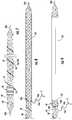
- FIG. 7is a side view of a wire wrapped over the braid of FIG. 5 towards a proximal end of the braid;
- FIG. 8is a side view of a first outer tube slid over a proximal end of the braid of FIG. 7 ;
- FIG. 9is a side view of an outer sleeve positioned over the first outer tube of FIG. 8 ;
- FIG. 10is a side view of the wire wrapped over a portion of the first outer tube and the outer sleeve of FIG. 9 ;
- FIG. 11is a side view of a second outer tube slid over a distal end of the braid, a portion of the wire, a portion of the first outer tube, and a portion of the outer sleeve of FIG. 10 ;
- FIG. 12is a side view of an outer coating formed over the braid from the first and second outer tubes with the wire unwrapped from over the outer sleeve and the outer sleeve removed from over the first outer tube of FIG. 11 ;
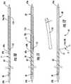
- FIG. 13is a side view of the catheter of FIG. 1 being cut to length from the braid, wire, and outer coating of FIG. 12 ;
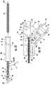
- FIG. 14is a side view of a proximal end portion of the catheter of FIG. 13 positioned in a body of a handle assembly with a half-shell of the body removed;
- FIG. 15is a side view of the catheter assembly of FIG. 1 with the half-shell of the body removed.
- This disclosurerelates generally to a catheter having an Extended Working Channel (EWC) and a sensor positioned at a distal end of the EWC for locating the distal end of the EWC within the anatomy of a patient.
- EWCExtended Working Channel
- a cathetereliminates the need for a separate locatable guide to be inserted through the EWC to locate the distal end of the catheter within the anatomy of a patient.
- such a cathetereliminates the need to remove the locatable guide before insertion of an instrument through the EWC to treat targeted tissue.
- such a catheteris locatable during an entire procedure such that the changes in the location of the distal end of the catheter are detectable and/or the catheter is repositionable during the procedure when an instrument positioned within the EWC.
- the term “clinician”refers to a doctor, a nurse, or any other care provider and may include support personnel.
- proximalrefers to the portion of the device or component thereof that is closest to the clinician and the term “distal” refers to the portion of the device or component thereof that is farthest from the clinician.
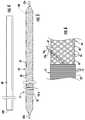
- a catheter assembly 10is provided in accordance with the present disclosure and includes a handle assembly 20 , a telescopic channel 30 , and an elongated catheter 50 having a proximal end portion 52 ( FIG. 12 ) and a distal end portion 54 .
- the handle assembly 20is positioned over the proximal end portion 52 of the catheter 50 to permit a clinician to manipulate the catheter assembly 10 .
- the telescopic channel 30is positioned over the catheter 50 between the proximal end portion 52 and the distal end portion 54 to provide lateral support for the elongated catheter 50 .
- the telescopic channel 30includes a proximal or first end 32 that is coupled to a distal end 24 of the handle assembly 20 and a distal or second end 36 that is configured to couple the catheter assembly 10 to a bronchoscope (not shown).
- the telescopic channel 30includes an extendable body portion 34 between the first and second ends 32 , 36 that is expandable along a longitudinal axis and substantially rigid transverse to the longitudinal axis.
- the extendable body portion 34allows the first end 32 to translate along and rotate about the longitudinal axis relative to the second end 36 .
- the proximal end portion 52 of the catheter 50translates and rotates with the first end 32 of the telescopic channel 30 .
- Examples of methods of marking the location of and registering a pathway to targeted tissuemay be found in commonly assigned U.S. Provisional Patent Application Nos. 62/020,177, filed Jul. 2, 2014, entitled “Methods for Marking Biopsy Location,” and 62/020,220, filed Jul. 2, 2014, entitled “Real-time Automatic Registration Feedback.”
- Examples of guiding a catheter to and treating targeted tissuemay be found in commonly assigned U.S. Patent Publication Nos. 2014/0281961 and 2014/0046315.
- Examples of bronchoscopes, handles, and support systems for microwave ablation cathetersmay be found in commonly assigned U.S. Patent Publication No. 2015/0073407. The entire contents of each of these disclosures are incorporated herein by reference.
- the catheter 50has a proximal end 53 ( FIG. 13 ) and a distal end 55 and defines an EWC 56 therebetween.
- the EWC 56allows instruments (not shown) to be inserted through the catheter 50 to treat targeted tissue adjacent the distal end 55 of the catheter 50 .
- the catheter 50includes a sensor 58 disposed at the distal end portion 54 of the catheter 50 adjacent the distal end 55 of the catheter 50 such that the distal end 55 of the catheter 50 is locatable within the anatomy of a patient.
- the catheter 50includes an inner liner 60 , a braid 64 , and an outer coating 68 .
- the inner liner 60defines the EWC 56 that passes entirely through the catheter 50 . It is contemplated that the catheter 50 may be constructed without the inner liner 60 such that the braid 64 defines the EWC 56 .
- the sensor 58is formed of a wire 71 ( FIG. 5 ) wrapped over the braid 64 and covered by the outer coating 68 to form the sensor 58 .
- the wire 71includes leads 76 a , 76 b that proximally follow the braid 64 to the proximal end portion 52 ( FIG. 12 ) of the catheter 50 .
- the wire 71is monolithically formed (i.e., the wire 71 is a continuous wire without any solder joints between different portions thereof).
- the inner liner 60 and the outer coating 68are formed from polymer tubes, as detailed below, which are made from of a reflowable polymer material (e.g., Arnitel®, Hytrel®, Pebax®, polytetrafluoroethylene (PTFE)) which may bond to the braid 64 , the wire 71 , and to one another.
- the braid 64is constructed of a mesh of between 16 and 32 of similar or varying material cords woven together (e.g., stainless steel, Dacron®, polyethylene naphthalate (PEN), polyethylene terephthalate (PET), and/or insulated electrical wire).
- the wire 71is a solid core magnetic wire with a thin dielectric coating (e.g., a copper wire with a polyimide coating).
- the inner liner 60is slid over a mandrel 100 .
- the mandrel 100provides rigidity to the flexible components of the catheter 50 while the catheter 50 is assembled.
- the inner liner 60has an inner diameter substantially equal to but slightly larger than an outer diameter of the mandrel 100 and has a length substantially equal to a length of the mandrel 100 .
- the mandrel 100may be coated with a PTFE coating to assist in sliding the inner liner 60 over the mandrel 100 and to prevent the inner liner 60 from bonding to the mandrel 100 .
- the outer diameter of the mandrel 100is substantially equal to a desired diameter of the EWC 56 ( FIG. 2 ) and the length of the mandrel 100 is longer than a final desired length of the catheter 50 .
- the mandrel 100may have a diameter in a range of about 0.050 to about 0.100 inches (e.g., about 0.090 inches) and have a length in a range of about 30 to about 90 inches (e.g., about 62 inches).
- the braid 64is formed over the inner liner 60 with portions of the braid 64 extending beyond the ends of the mandrel 100 such that the mandrel 100 and the inner liner 60 are completely within the braid 64 .
- the ends 65 a , 65 b of the braid 64 that extend beyond the mandrel 100may have a diameter less than the diameter of the mandrel 100 .
- the ends 65 a , 65 b of the braid 64may retain the mandrel 100 within the braid 64 during construction of the catheter 50 . It is contemplated that the braid 64 may be preformed and slid over the inner liner 60 and the mandrel 100 .
- the braid 64is formed by helically weaving cords 66 of material over a cylinder (e.g., the inner liner 60 and the mandrel 100 .
- the cords 66define channels 67 therebetween that follow the helical pattern of the cords 66 .
- the pitch of the cords 66is in a range of about 0.125 to about 0.225 (e.g., about 0.177).
- the braid 64may compress the inner liner 60 over the mandrel 100 .
- the braid 64has an outer diameter in a range of about 0.052 to about 0.102 inches (e.g., 0.092 inches). It is contemplated that the inner liner 60 , the braid 64 , and the mandrel 100 may be supplied as a preassembled unit.
- the sensor 58is formed by wrapping the wire 71 over the braid 64 , or over the mandrel 100 and inner liner 60 just distal to the braid termination, transverse to a longitudinal axis of the braid to form wraps 72 over the braid 64 , or over the mandrel 100 and inner liner 60 .
- the wraps 72may include an inner layer 72 a and an outer layer 72 b of wraps 72 .
- Each layer of wraps 72 a , 72 bmay include a range of about 25 to about 200 individual wraps 72 (e.g., about 100 individual wraps) of the wire 71 .
- the number of wraps 72 in the inner layer 72 amay be substantially equal to the number of wraps 72 of the outer layer 72 b.
- the sensor 58includes two layers of wraps 72 a , 72 b ; however, it is contemplated that the sensor 58 may include a single layer of wraps 72 or may include more than two layers of wraps 72 .
- the number of wraps 72 of the wire 71is proportional to signal strength of the sensor 58 . That is, as the number of wraps 72 increases, the signal strength of the sensor 58 increases. As the number of layers of wraps 72 is increased, the flexibility of the catheter 50 in the area of the wraps 72 is reduced and the diameter of the catheter 50 in the area of the wraps 72 is increased.
- the total length of the layers 72 a , 72 b of the wraps 72is in a range of about 0.04 to about 0.36 inches (e.g., about 0.18 inches). As the total length of the layers 72 a , 72 b is increased, the flexibility of the catheter 50 in the area of the wraps 72 is reduced. Thus, the number of layers of wraps 72 , the length of the wraps 72 , and the total number of wraps 72 is a compromise between the signal strength of the sensor 58 and the flexibility and size of the catheter 50 .
- the wraps 72are formed by ends or leads 76 a , 76 b of the wire 71 being wrapped around about the braid 64 .
- the inner and outer layers 72 a , 72 bmay be formed simultaneously by beginning at a distance spaced away from a distal end 65 b of the braid 64 .
- the inner layer 72 ais formed by a first lead 76 a being wrapped around the braid 64 in a first direction substantially transverse to a longitudinal axis of the braid 64 while proximally traversing an outer surface of the braid 64 .
- the outer layer 72 bis formed by a second lead 76 b being wrapped around the braid 64 and the inner layer 72 a in a second direction, opposite to the first direction, substantially transverse to a longitudinal axis of the braid 64 while proximally traversing the inner layer 72 a .
- the wrapping of the second lead 76 btrails the wrapping of the first lead 76 a in a range of about 1 to about 5 wraps 72 of the wire 71 (e.g., 2 wraps) to allow the inner layer 72 a to form before being covered by the outer layer 72 b .
- the wraps 72are started spaced away from the distal end 65 b of the braid 64 a distance in a range of about 0.0 to about 3.0 inches (e.g., about 0.5 inches).
- the wraps 72are spaced away a distance from the distal end 65 b of the braid 64 large enough to ensure that the inner liner 60 and the braid 64 are substantially cylindrical in shape in the region of the wraps 72 while minimizing the distance the wraps 72 are space away from the distal end 65 b to reduce wasted materials.
- one leadexits the sensor 58 at a proximal end of the sensor 58 and the other lead exits the sensor at a distal end of the sensor 58 .
- the lead that exits the sensor 58 at the distal endis placed under or over the wraps 72 prior to wrapping the leads 76 a , 76 b over the braid 64 as detailed below.
- a support tube or layermay be positioned over the braid 64 before the wire 71 is wrapped over the braid 64 to form the sensor 58 or may be placed over the sensor 58 after the wire 71 is wrapped over the braid to form the sensor 58 .
- the support layermay be a ferro-metallic tube or a powder with resin that is configured to strengthen or support the sensor 58 to prevent the sensor 58 from deforming when used.
- the support layermay increase the signal strength of the sensor 58 such that the length and/or number of wraps 72 required to achieve a desired signal strength for the sensor 58 may be reduced.
- the leads 76 a , 76 bare brought together within a channel 67 defined between two cords 66 of the braid 64 at a proximal end of the wraps 72 .
- the leads 76 a , 76 b of the wire 71are twisted together to form a twisted pair to reduce or eliminate a signal from being generated by the wire 71 along the length of the braid 64 (i.e., utilizing the constructive interference to minimize the signal generated).
- the leads 76 a , 76 bare twisted together in a range of about 5 to about 15 twists per inch (e.g., about 10 twists per inch) of the wire 71 .
- the twisted pair of leads 76 a , 76 bis wrapped around the braid 64 within a channel 67 of the braid 64 such that the twisted pair of leads 76 a , 76 b follows the pitch of the braid 64 as shown in FIG. 7 . Wrapping the twisted pair of leads 76 a , 76 b helically around the braid 64 may increase the fatigue life of the leads 76 a , 76 b in response to flexing of the catheter 50 along its longitudinal axis.
- the twisted pair of leads 76 a , 76 bis wrapped about the braid 64 from the wraps 72 along a substantial length of the braid 64 towards a proximal end 65 a of the braid 64 .
- the twisted pair of leads 76 a , 76 bare wrapped about the braid 64 in a clockwise direction when viewed from the proximal end 65 a of the braid 64 ; however, the twisted pair of leads 76 a , 76 b may be wrapped about the braid 64 in a counter-clockwise direction when viewed from the proximal end 65 a of the braid 64 .
- By forming the wraps 72 and the twisted pair of leads 76 a , 76 b with a single continuous wireincreases the service life of the catheter 50 by eliminating the need for a connection (e.g., a soldered connection) between the wraps 72 and each of the twisted pair of leads 76 a , 76 b.
- a single device or a combination of devicesmay be used to wrap the wire 71 about the braid 64 to form the wraps 72 , twist the pair of leads 76 a , 76 b of the wire 71 together, and wrap the twisted pair of leads 76 a , 76 b of the wire 71 about the braid 64 .
- the wraps 72 and the twisted pair of leads 76 a , 76 bmay be preformed apart from the braid and then positioned or loaded over the braid 64 . Once the wraps 72 are loaded over the braid 64 , the twisted pair of leads 76 a , 76 b are wrapped about the braid 64 as detailed above.
- a first outer tube 69is slid over the proximal end 65 a of the braid 64 until a proximal end 69 a of the first outer tube 69 is adjacent to the twisted pair of leads 76 a , 76 b .
- the first outer tube 69is a polymer tube which is then covered by heat shrink to melt or reflow the polymer such that the first outer tube 69 reflows or bonds to the braid 64 .
- the inner liner 60 within the first outer tube 69may be reflowed to bond with the braid 64 and the first outer tube 69 .
- the outer diameter of the first outer tube 69may be slightly reduced as the first outer tube 69 is reflowed.
- an outer sleeve 110is slid over the reflowed first outer tube 69 until a distal end 112 of the outer sleeve 110 is adjacent a distal end 69 a of the first outer tube 69 .
- a portion 69 b of the first outer tube 69is exposed between the twisted pair of leads 76 a , 76 b and the outer sleeve 110 .
- the twisted pair of leads 76 a , 76 bis then wrapped over the exposed portion 69 b of the reflowed first outer tube 69 and over the outer sleeve 110 as shown in FIG. 10 .
- the outer sleeve 110is constructed of or lined with PTFE such that the outer sleeve 110 and the leads 76 a , 76 b are prevented from bonding to a portion of the reflowed first outer tube 69 covered by the outer sleeve 110 .
- a second outer tube 70is slid over the distal end 65 b of the braid 64 , the sensor 58 , the twisted pair of leads 76 a , 76 b , the exposed portion 69 b of the first outer tube 69 , and a portion of the outer sleeve 110 .
- the second outer tube 70Similar to the first outer tube 69 , the second outer tube 70 has an inner diameter slightly larger than the braid 64 such that the second outer tube 70 freely slides over the braid 64 , the wire 71 , the reflowed first outer tube 64 , and the outer sleeve 110 .
- a proximal end 70 a of the second outer tube 70is positioned along the outer sleeve 110 .
- the second outer tube 70is a polymer tube which is then covered by heat shrink to reflow the polymer such that the second outer tube 70 bonds to the braid 64 and to the exposed portion 69 b of the first outer tube 69 .
- the inner liner 60 and the first inner tube 69 within the second outer tube 70may be reflowed to bond with the braid 64 , the second outer tube 70 , and the wire 71 .
- the first and second outer tubes 69 , 70form the outer coating 68 as a continuous layer of polymer over the braid 64 and a substantial portion of the wire 71 .
- the outer coating 68is substantially smooth and seals the EWC 64 ( FIG. 3 ). As shown, the outer coating 68 is translucent or transparent; however, the outer coating 68 may be opaque and have a desired color (e.g., blue or white).
- the twisted pair of leads 76 a , 76 bis unwrapped from over the outer sleeve 110 in a manner not to damage the leads 76 a , 76 b . Then the outer sleeve 110 is peeled off or removed from over the portion of the outer coating 68 previously formed from first outer tube 69 . Any portion of the second outer tube 70 that is formed over the outer sleeve 110 is separated from the outer coating 68 and discarded.
- the catheter 50is cut adjacent the proximal end 65 a of the braid 64 to define a proximal end 53 of the catheter 50 .
- the catheter 50is cut a distance spaced away from a point 77 where the leads 76 a , 76 b pass through the outer coating 68 to leave a proximal end portion 52 of the catheter 50 where the leads 76 a , 76 b are not wrapped around the braid 64 .
- the catheter 50is also cut adjacent the sensor 58 to define the distal end 55 of the catheter 50 .
- the cut adjacent the sensor 58is spaced apart a minimal distance from the sensor 58 to prevent discontinuities in the wire 71 forming the sensor 58 ; however, this distance is minimized to allow the sensor 58 to be positioned as close to the distal end 55 of the catheter as possible.
- the distal end 55 of the catheter 50may be reflowed to seal the portions of the braid 64 exposed by cutting adjacent the sensor. Additionally or alternatively, a catheter tip (not shown) may also be bonded to the distal end 55 of the catheter 50 . After the catheter 50 is cut, the catheter 50 has a total length of about 30 to about 90 inches (e.g., about 60 inches) from the proximal end 53 to the distal end 55 .
- a hub 80is positioned over the proximal end portion 52 of the catheter 50 .
- the hub 80defines a channel 81 therethrough and includes a proximal guide portion 82 , a central collar 84 , and a distal collar 86 .
- the proximal end portion 52 of the catheter 50is positioned within the channel 81 of the hub 80 such that the proximal end 53 of the catheter is adjacent the central collar 84 of the hub 80 .
- the hub 80is then bonded to the proximal end portion 52 of the catheter 50 .
- the hub 80may be reflowed into the outer coating 68 of the catheter 50 or bonded to the outer coating 68 using adhesives.
- the proximal guide portion 82is configured to guide an instrument (not shown) into the EWC ( FIG. 3 ) of the catheter 50 .
- the handle assembly 20is coupled over the proximal end portion 52 of the catheter 50 .
- the handle assembly 20includes a body 21 formed from two half shells coupled together over the proximal end portion 52 of the catheter 50 .
- Each of the half shells of the body 21is substantially similar to one another and is joined along the longitudinal axis of the catheter 50 .
- the body 21has a proximal end 22 , a distal end 24 , and a connector portion 26 .
- the body 21defines a catheter passage 28 that is configured to receive the catheter 50 with the hub 80 bonded to the distal end 52 .
- the catheter passage 28includes an enlarged proximal portion 29 including a first recess 29 a and a second recess 29 b .
- the proximal portion 29is sized to receive the hub 80 to longitudinally fix the catheter 50 relative to the handle 20 .
- the first recess 29 ais sized to receive the central collar 84 of the hub 80 and the second recess 29 b is sized to receive the distal collar 86 of the hub 80 .
- the proximal portion 29 of the catheter passage 28 between the first and second recesses 29 a , 29 bhas a diameter smaller than the first and second recesses 29 a , 29 b to fix the hub 80 within the catheter passage 28 .
- the hub 80is frictionally engaged with the body 21 to rotatably secure the hub 80 within the catheter passage 28 . It is contemplated that the hub 80 may be adhered to the body 21 within the catheter passage 28 .
- the handle 20includes an electrical coupling 90 disposed within a cavity 27 of the connector portion 26 of the handle 20 .
- the electrical coupling 90inlcudes an internal connector 92 , an external connector 94 , and a collar 96 positioned between the internal and external connectors 92 , 94 .
- the collar 96is received by the connector portion 26 of the handle 20 to form a seal to isolate the internal connector 92 within the cavity 27 of the connector portion 26 .
- the cavity 27 of the connector portion 26is isolated from the external environment by a seal formed by the walls defining the catheter passage 28 engaging the outer coating 68 of the catheter 50 and the seal formed by the collar 96 engaging walls defining the cavity 27 of the connector portion 26 .
- the point 77 at which the twisted pair of the leads 76 a , 76 b exits through the outer coating 68 of the catheter 50is positioned within the cavity 27 of the connector portion 26 .
- the leads 76 a , 76 bare untwisted from one another and electrically coupled (e.g., soldered) separately to the internal connector 92 .
- the internal connector 92is in electrical communication with the external connector 94 such that an adapter (not shown) may be coupled to the external connector 94 to supply electrical energy to the sensor 58 ( FIG. 1 ) through the external connector 94 via the wire 71 . Examples of systems and methods for using the sensor 58 to guiding the catheter 50 to targeted tissue may be found in commonly assigned U.S. Patent Publication Nos. 2014/0281961 and 2014/0046315.
- the distal end 24 of the body 21defines an opening 25 a configured to receive the first end 32 of the telescopic channel 30 .
- the body 21may define a slot 25 b parallel to the catheter passage 28 and in communication with the opening 25 a to receive a clip 33 of the first end 32 of the telescopic channel 30 to rotatably fix the first end 32 of the telescopic channel 30 to the body 21 .
- the distal end 24 of the body 21may also include a ring 25 c positioned about an outer surface of the body 21 transverse to the longitudinal axis of the catheter passage 28 and over the slot 25 b .
- the clip 33 of the first end 32 of the telescopic channel 30may engage the ring 25 c when the clip 33 is disposed within the slot 25 b to longitudinally the first end 32 of the telescopic channel 30 to the body 21 of the handle 20 .
- the telescopic channel 30may be attached a bronchoscope (not shown) and the catheter 50 of the catheter assembly 10 may be inserted through the first end 32 of the telescopic channel 30 until the distal end 24 of the handle 20 receives the first end 32 of the telescopic channel 30 .
Landscapes
- Health & Medical Sciences (AREA)
- Life Sciences & Earth Sciences (AREA)
- Engineering & Computer Science (AREA)
- Veterinary Medicine (AREA)
- Biomedical Technology (AREA)
- Heart & Thoracic Surgery (AREA)
- Animal Behavior & Ethology (AREA)
- General Health & Medical Sciences (AREA)
- Public Health (AREA)
- Surgery (AREA)
- Biophysics (AREA)
- Pathology (AREA)
- Molecular Biology (AREA)
- Medical Informatics (AREA)
- Physics & Mathematics (AREA)
- Pulmonology (AREA)
- Human Computer Interaction (AREA)
- Hematology (AREA)
- Anesthesiology (AREA)
- Nuclear Medicine, Radiotherapy & Molecular Imaging (AREA)
- Oral & Maxillofacial Surgery (AREA)
- Otolaryngology (AREA)
- Physiology (AREA)
- Optics & Photonics (AREA)
- Radiology & Medical Imaging (AREA)
- Media Introduction/Drainage Providing Device (AREA)
Abstract
Description
Claims (19)
Priority Applications (4)
| Application Number | Priority Date | Filing Date | Title |
|---|---|---|---|
| US15/228,321US10575754B2 (en) | 2015-09-23 | 2016-08-04 | Catheter having a sensor and an extended working channel |
| EP16189889.5AEP3150248B1 (en) | 2015-09-23 | 2016-09-21 | Method of manufacturing an elongated catheter having sensor and an extended working channel |
| US16/805,940US10939846B2 (en) | 2015-09-23 | 2020-03-02 | Elongated catheter having sensor and an extended working channel |
| US17/165,104US11918338B2 (en) | 2015-09-23 | 2021-02-02 | Elongated catheter having sensor and an extended working channel |
Applications Claiming Priority (2)
| Application Number | Priority Date | Filing Date | Title |
|---|---|---|---|
| US201562222449P | 2015-09-23 | 2015-09-23 | |
| US15/228,321US10575754B2 (en) | 2015-09-23 | 2016-08-04 | Catheter having a sensor and an extended working channel |
Related Child Applications (1)
| Application Number | Title | Priority Date | Filing Date |
|---|---|---|---|
| US16/805,940ContinuationUS10939846B2 (en) | 2015-09-23 | 2020-03-02 | Elongated catheter having sensor and an extended working channel |
Publications (2)
| Publication Number | Publication Date |
|---|---|
| US20170079546A1 US20170079546A1 (en) | 2017-03-23 |
| US10575754B2true US10575754B2 (en) | 2020-03-03 |
Family
ID=57211247
Family Applications (3)
| Application Number | Title | Priority Date | Filing Date |
|---|---|---|---|
| US15/228,321Active2038-02-11US10575754B2 (en) | 2015-09-23 | 2016-08-04 | Catheter having a sensor and an extended working channel |
| US16/805,940ActiveUS10939846B2 (en) | 2015-09-23 | 2020-03-02 | Elongated catheter having sensor and an extended working channel |
| US17/165,104Active2038-04-07US11918338B2 (en) | 2015-09-23 | 2021-02-02 | Elongated catheter having sensor and an extended working channel |
Family Applications After (2)
| Application Number | Title | Priority Date | Filing Date |
|---|---|---|---|
| US16/805,940ActiveUS10939846B2 (en) | 2015-09-23 | 2020-03-02 | Elongated catheter having sensor and an extended working channel |
| US17/165,104Active2038-04-07US11918338B2 (en) | 2015-09-23 | 2021-02-02 | Elongated catheter having sensor and an extended working channel |
Country Status (2)
| Country | Link |
|---|---|
| US (3) | US10575754B2 (en) |
| EP (1) | EP3150248B1 (en) |
Cited By (1)
| Publication number | Priority date | Publication date | Assignee | Title |
|---|---|---|---|---|
| US10939846B2 (en) | 2015-09-23 | 2021-03-09 | Covidien Lp | Elongated catheter having sensor and an extended working channel |
Families Citing this family (10)
| Publication number | Priority date | Publication date | Assignee | Title |
|---|---|---|---|---|
| JP6604654B2 (en)* | 2016-06-24 | 2019-11-13 | 朝日インテック株式会社 | catheter |
| EP4018946A1 (en) | 2017-05-03 | 2022-06-29 | Medtronic Vascular, Inc. | Tissue-removing catheter |
| US11690645B2 (en) | 2017-05-03 | 2023-07-04 | Medtronic Vascular, Inc. | Tissue-removing catheter |
| US10773053B2 (en) | 2018-01-24 | 2020-09-15 | Covidien Lp | Methods of manufacturing a catheter having a sensor |
| US10773051B2 (en) | 2018-01-24 | 2020-09-15 | Covidien Lp | Methods of manufacturing a catheter having a sensor |
| US11495141B2 (en) | 2018-03-29 | 2022-11-08 | Cae Healthcare Canada Inc. | Dual channel medical simulator |
| DE102018121206A1 (en)* | 2018-08-30 | 2020-03-05 | Karl Storz Se & Co. Kg | Endoscopic shaft with a layered structure and method for producing such |
| US11975157B2 (en)* | 2019-04-12 | 2024-05-07 | Covidien Lp | Method of manufacturing an elongated catheter having multiple sensors for three-dimensional location of the catheter |
| US11819236B2 (en) | 2019-05-17 | 2023-11-21 | Medtronic Vascular, Inc. | Tissue-removing catheter |
| WO2024166097A1 (en)* | 2023-02-08 | 2024-08-15 | Magnisity Ltd. | Combined curve temperature and shape sensor |
Citations (39)
| Publication number | Priority date | Publication date | Assignee | Title |
|---|---|---|---|---|
| EP0421650A1 (en) | 1989-10-06 | 1991-04-10 | C.R. Bard, Inc. | Multilaminate coiled film catheter construction |
| US5386828A (en) | 1991-12-23 | 1995-02-07 | Sims Deltec, Inc. | Guide wire apparatus with location sensing member |
| US5727553A (en)* | 1996-03-25 | 1998-03-17 | Saad; Saad A. | Catheter with integral electromagnetic location identification device |
| US5830222A (en) | 1995-10-13 | 1998-11-03 | Transvascular, Inc. | Device, system and method for intersititial transvascular intervention |
| US5938603A (en)* | 1997-12-01 | 1999-08-17 | Cordis Webster, Inc. | Steerable catheter with electromagnetic sensor |
| US6078830A (en) | 1997-10-01 | 2000-06-20 | Ep Technologies, Inc. | Molded catheter distal end assembly and process for the manufacture thereof |
| US6213995B1 (en)* | 1999-08-31 | 2001-04-10 | Phelps Dodge High Performance Conductors Of Sc And Ga, Inc. | Flexible tubing with braided signal transmission elements |
| US6253770B1 (en) | 1996-02-15 | 2001-07-03 | Biosense, Inc. | Catheter with lumen |
| US6503353B1 (en)* | 1996-05-13 | 2003-01-07 | Schneider (Usa) Inc. | Method for making a catheter |
| US6690963B2 (en)* | 1995-01-24 | 2004-02-10 | Biosense, Inc. | System for determining the location and orientation of an invasive medical instrument |
| US20050015044A1 (en) | 2001-08-30 | 2005-01-20 | Herbert Harttig | Catheter and method for producing the same |
| US6869431B2 (en) | 1997-07-08 | 2005-03-22 | Atrionix, Inc. | Medical device with sensor cooperating with expandable member |
| US20060287700A1 (en) | 2005-06-21 | 2006-12-21 | Cardiomems, Inc. | Method and apparatus for delivering an implantable wireless sensor for in vivo pressure measurement |
| US7386339B2 (en) | 1999-05-18 | 2008-06-10 | Mediguide Ltd. | Medical imaging and navigation system |
| US20090018566A1 (en) | 2006-06-30 | 2009-01-15 | Artheromed, Inc. | Atherectomy devices, systems, and methods |
| US20090234328A1 (en) | 2007-11-26 | 2009-09-17 | C.R. Bard, Inc. | Systems and methods for breaching a sterile field for intravascular placement of a catheter |
| US7668583B2 (en) | 2002-06-10 | 2010-02-23 | Rayonex Schwingungstechnik Gmbh | Method and apparatus for control and location of an instrument or appliance |
| US20100331644A1 (en) | 2008-11-07 | 2010-12-30 | Dexcom, Inc. | Housing for an intravascular sensor |
| US20110066029A1 (en) | 2009-09-11 | 2011-03-17 | Medtronic, Inc. | Electromagnetic Medical Device |
| US7927271B2 (en)* | 2006-05-17 | 2011-04-19 | C.R. Bard, Inc. | Endoscope tool coupling |
| US20120149967A1 (en) | 2010-12-10 | 2012-06-14 | Doron Moshe Ludwin | System and method for detection of metal disturbance based on orthogonal field components |
| US20120172842A1 (en) | 2010-12-30 | 2012-07-05 | Ran Sela | Method of assembling a positioning sensor and associated wiring on a medical tool |
| US8285362B2 (en) | 2007-06-28 | 2012-10-09 | W. L. Gore & Associates, Inc. | Catheter with deflectable imaging device |
| US8287453B2 (en) | 2003-12-05 | 2012-10-16 | Dexcom, Inc. | Analyte sensor |
| US20120265102A1 (en) | 2011-04-14 | 2012-10-18 | Giovanni Leo | Compact force sensor for catheters |
| US8361066B2 (en) | 2009-01-12 | 2013-01-29 | Ethicon Endo-Surgery, Inc. | Electrical ablation devices |
| US20130169272A1 (en)* | 2011-12-30 | 2013-07-04 | Uzi Eichler | Roll detection and six degrees of freedom sensor assembly |
| US20130245433A1 (en) | 2010-11-18 | 2013-09-19 | Koninklijke Philips Electronics N.V. | Location determination apparatus |
| US8611984B2 (en)* | 2009-04-08 | 2013-12-17 | Covidien Lp | Locatable catheter |
| US8857304B2 (en) | 2010-12-02 | 2014-10-14 | Biosense Webster (Israel), Ltd. | Magnetic resonance imaging compatible catheter |
| US20150080858A1 (en) | 2013-09-18 | 2015-03-19 | Gerald Moss | Catheter and method of making the same |
| US9078570B2 (en) | 2003-10-10 | 2015-07-14 | Sierra Scientific Instruments, Inc. | High resolution solid state pressure sensor |
| CN104840249A (en) | 2011-04-08 | 2015-08-19 | 柯惠有限合伙公司 | Flexible microwave catheters for natural or artificial lumens |
| US9125578B2 (en) | 2009-06-12 | 2015-09-08 | Bard Access Systems, Inc. | Apparatus and method for catheter navigation and tip location |
| US9144458B2 (en) | 2009-05-21 | 2015-09-29 | Toray Industries, Inc. | Ablation catheter with balloon and ablation catheter system with balloon |
| WO2015160064A1 (en) | 2014-04-18 | 2015-10-22 | 부경대학교산학협력단 | Probe comprising optically diffusing fiber, method for manufacturing same and applications thereof |
| US20150374435A1 (en) | 2013-02-07 | 2015-12-31 | Shanghai Golden Leaf Med Tec Co., Ltd | Radio frequency ablation method, system and radio frequency ablation device thereof |
| CN105615991A (en) | 2014-11-05 | 2016-06-01 | 上海微创电生理医疗科技有限公司 | Ablation catheter |
| US20160184013A1 (en) | 2014-12-31 | 2016-06-30 | Covidien Lp | System and method for treating copd and emphysema |
Family Cites Families (71)
| Publication number | Priority date | Publication date | Assignee | Title |
|---|---|---|---|---|
| US4202352A (en) | 1978-04-06 | 1980-05-13 | Research Development Corporation | Apparatus for measurement of expired gas concentration in infants |
| AU658932B2 (en) | 1991-10-18 | 1995-05-04 | Ethicon Inc. | Endoscopic tissue manipulator |
| GB2329840C (en) | 1997-10-03 | 2007-10-05 | Johnson & Johnson Medical | Biopolymer sponge tubes |
| US6086586A (en) | 1998-09-14 | 2000-07-11 | Enable Medical Corporation | Bipolar tissue grasping apparatus and tissue welding method |
| US6413981B1 (en) | 1999-08-12 | 2002-07-02 | Ortho-Mcneil Pharamceutical, Inc. | Bicyclic heterocyclic substituted phenyl oxazolidinone antibacterials, and related compositions and methods |
| US20050165276A1 (en) | 2004-01-28 | 2005-07-28 | Amir Belson | Methods and apparatus for accessing and treating regions of the body |
| US6656177B2 (en) | 2000-10-23 | 2003-12-02 | Csaba Truckai | Electrosurgical systems and techniques for sealing tissue |
| US6472372B1 (en) | 2000-12-06 | 2002-10-29 | Ortho-Mcneil Pharmaceuticals, Inc. | 6-O-Carbamoyl ketolide antibacterials |
| US6533784B2 (en) | 2001-02-24 | 2003-03-18 | Csaba Truckai | Electrosurgical working end for transecting and sealing tissue |
| US6913579B2 (en) | 2001-05-01 | 2005-07-05 | Surgrx, Inc. | Electrosurgical working end and method for obtaining tissue samples for biopsy |
| US6802843B2 (en) | 2001-09-13 | 2004-10-12 | Csaba Truckai | Electrosurgical working end with resistive gradient electrodes |
| US8298161B2 (en) | 2002-09-12 | 2012-10-30 | Intuitive Surgical Operations, Inc. | Shape-transferring cannula system and method of use |
| US7947000B2 (en) | 2003-09-12 | 2011-05-24 | Intuitive Surgical Operations, Inc. | Cannula system for free-space navigation and method of use |
| US9808597B2 (en) | 2002-09-12 | 2017-11-07 | Intuitive Surgical Operations, Inc. | Shape-transferring cannula system and method of use |
| US20060235457A1 (en) | 2005-04-15 | 2006-10-19 | Amir Belson | Instruments having a rigidizable external working channel |
| JP2009507617A (en) | 2005-09-14 | 2009-02-26 | ネオガイド システムズ, インコーポレイテッド | Method and apparatus for performing transluminal and other operations |
| US8517955B2 (en) | 2009-05-08 | 2013-08-27 | Broncus Medical Inc. | Tissue sampling devices, systems and methods |
| KR102359695B1 (en) | 2011-02-15 | 2022-02-09 | 인튜어티브 서지컬 오퍼레이션즈 인코포레이티드 | Systems for detecting clamping or firing failure |
| US9393017B2 (en) | 2011-02-15 | 2016-07-19 | Intuitive Surgical Operations, Inc. | Methods and systems for detecting staple cartridge misfire or failure |
| US9387048B2 (en) | 2011-10-14 | 2016-07-12 | Intuitive Surgical Operations, Inc. | Catheter sensor systems |
| US20130096385A1 (en) | 2011-10-14 | 2013-04-18 | Intuitive Surgical Operations, Inc. | Vision probe and catheter systems |
| JP6290099B2 (en) | 2012-02-03 | 2018-03-07 | インテュイティブ サージカル オペレーションズ, インコーポレイテッド | Steerable flexible needle with implantable shape sensing function |
| US9993295B2 (en) | 2012-08-07 | 2018-06-12 | Covidien Lp | Microwave ablation catheter and method of utilizing the same |
| WO2014028622A1 (en) | 2012-08-15 | 2014-02-20 | Intuitive Surgical Operations, Inc. | Specimen removal bag and methods of using same |
| US11172809B2 (en) | 2013-02-15 | 2021-11-16 | Intuitive Surgical Operations, Inc. | Vision probe with access port |
| US9459770B2 (en) | 2013-03-15 | 2016-10-04 | Covidien Lp | Pathway planning system and method |
| AU2014317930B2 (en) | 2013-09-06 | 2018-11-08 | Covidien Lp | Microwave ablation catheter, handle, and system |
| EP3653156B1 (en) | 2013-10-25 | 2023-08-02 | Intuitive Surgical Operations, Inc. | Flexible instrument with grooved steerable tube |
| WO2015075558A2 (en) | 2013-11-25 | 2015-05-28 | Body Vision Medical Ltd. | Surgical devices and methods of use thereof |
| CN114366181B (en) | 2013-12-13 | 2024-08-02 | 直观外科手术操作公司 | Telescopic biopsy needle |
| JP6629230B2 (en) | 2014-04-02 | 2020-01-15 | インテュイティブ サージカル オペレーションズ, インコーポレイテッド | Minimal invasive system |
| US9801630B2 (en) | 2014-06-10 | 2017-10-31 | Ethicon Llc | Methods and devices for reinforcing a staple line |
| US10206686B2 (en) | 2014-06-10 | 2019-02-19 | Ethicon Llc | Bronchus sealants and methods of sealing bronchial tubes |
| US10792464B2 (en) | 2014-07-01 | 2020-10-06 | Auris Health, Inc. | Tool and method for using surgical endoscope with spiral lumens |
| CN107072721B (en) | 2014-07-28 | 2020-03-20 | 直观外科手术操作公司 | Guide apparatus for delivery of flexible instruments and methods of use |
| EP3179898B1 (en) | 2014-08-14 | 2021-10-06 | Intuitive Surgical Operations, Inc. | Systems and methods for cleaning an endoscopic instrument |
| US11273290B2 (en) | 2014-09-10 | 2022-03-15 | Intuitive Surgical Operations, Inc. | Flexible instrument with nested conduits |
| WO2016040128A1 (en) | 2014-09-10 | 2016-03-17 | Intuitive Surgical Operations, Inc. | Devices, systems, and methods using mating catheter tips and tools |
| WO2016114981A1 (en) | 2015-01-12 | 2016-07-21 | Intuitive Surgical Operations, Inc. | Devices, systems, and methods for anchoring actuation wires to a steerable instrument |
| US10245034B2 (en) | 2015-08-31 | 2019-04-02 | Ethicon Llc | Inducing tissue adhesions using surgical adjuncts and medicants |
| US10172973B2 (en) | 2015-08-31 | 2019-01-08 | Ethicon Llc | Surgical adjuncts and medicants for promoting lung function |
| US10349938B2 (en) | 2015-08-31 | 2019-07-16 | Ethicon Llc | Surgical adjuncts with medicants affected by activator materials |
| US10575754B2 (en) | 2015-09-23 | 2020-03-03 | Covidien Lp | Catheter having a sensor and an extended working channel |
| BR112018008233B1 (en) | 2015-10-26 | 2022-10-04 | Neuwave Medical, Inc | APPARATUS FOR FASTENING A MEDICAL DEVICE, METHOD FOR FASTENING A MEDICAL DEVICE IN A DESIRED POSITION, AND KIT |
| US9955986B2 (en) | 2015-10-30 | 2018-05-01 | Auris Surgical Robotics, Inc. | Basket apparatus |
| CN109069136B (en) | 2015-10-30 | 2021-07-20 | 奥瑞斯健康公司 | Procedure for percutaneous surgery |
| WO2017083129A1 (en) | 2015-11-13 | 2017-05-18 | Intuitive Surgical Operations, Inc. | Stapler anvil with compliant tip |
| US10258326B2 (en) | 2016-02-08 | 2019-04-16 | Ethicon, Inc. | Elastic tissue reinforcing fastener |
| US10702137B2 (en) | 2016-03-14 | 2020-07-07 | Intuitive Surgical Operations, Inc.. | Endoscopic instrument with compliant thermal interface |
| US20170274189A1 (en) | 2016-03-24 | 2017-09-28 | Ethicon, Inc. | Single lumen balloon delivery catheter with lumen bypass at balloon |
| WO2017189272A1 (en) | 2016-04-29 | 2017-11-02 | Intuitive Surgical Operations, Inc. | Compliant mechanisms having inverted tool members |
| US20200077991A1 (en) | 2016-05-31 | 2020-03-12 | Intuitive Surgical Operations, Inc. | Pliant biopsy needle system |
| CN109310287B (en) | 2016-07-01 | 2023-01-03 | 直观外科手术操作公司 | Computer-aided medical system and control method thereof |
| US10729886B2 (en) | 2016-08-24 | 2020-08-04 | Intuitive Surgical Operations, Inc. | Axial support structure for a flexible elongate device |
| US10881385B2 (en) | 2016-09-13 | 2021-01-05 | Intuitive Surgical Operations, Inc. | Radial telescoping guide apparatus for delivery of a flexible instrument and methods of use |
| EP3512435B1 (en) | 2016-09-14 | 2023-11-01 | Intuitive Surgical Operations, Inc. | Joint assemblies with cross-axis flexural pivots |
| US10682192B2 (en) | 2016-09-30 | 2020-06-16 | Intuitive Surgical Operations, Inc. | Variable-length guide apparatus for delivery of a flexible instrument and methods of use |
| AU2017339213A1 (en) | 2016-10-07 | 2019-05-02 | Body Vision Medical Ltd | Devices for use in interventional and surgical procedures and methods of use thereof |
| US11517184B2 (en) | 2017-02-01 | 2022-12-06 | Intuitive Surgical Operations, Inc. | Systems and methods of registration for image-guided procedures |
| WO2018148544A1 (en) | 2017-02-09 | 2018-08-16 | Intuitive Surgical Operations, Inc. | Systems and methods of accessing encapsulated targets |
| US10285574B2 (en) | 2017-04-07 | 2019-05-14 | Auris Health, Inc. | Superelastic medical instrument |
| WO2019018736A2 (en) | 2017-07-21 | 2019-01-24 | Intuitive Surgical Operations, Inc. | Flexible elongate device systems and methods |
| CN111386086A (en) | 2017-11-14 | 2020-07-07 | 直观外科手术操作公司 | System and method for cleaning endoscopic instruments |
| CN111770736A (en) | 2017-12-11 | 2020-10-13 | 奥瑞斯健康公司 | Systems and methods for instrument-based insertion architectures |
| US11696760B2 (en) | 2017-12-28 | 2023-07-11 | Cilag Gmbh International | Safety systems for smart powered surgical stapling |
| US20190246876A1 (en) | 2018-02-15 | 2019-08-15 | Neuwave Medical, Inc. | Compositions and methods for directing endoscopic devices |
| US11298505B2 (en) | 2018-03-05 | 2022-04-12 | Intuitive Surgical Operations, Inc. | Deployable bellows for delivery of a flexible, elongate device and methods of use |
| US11678788B2 (en) | 2018-07-25 | 2023-06-20 | Intuitive Surgical Operations, Inc. | Systems and methods for use of a variable stiffness flexible elongate device |
| US20200029948A1 (en) | 2018-07-26 | 2020-01-30 | Intuitive Surgical Operations, Inc. | Systems and methods of steerable elongate device |
| US11576738B2 (en) | 2018-10-08 | 2023-02-14 | Auris Health, Inc. | Systems and instruments for tissue sealing |
| US11617627B2 (en) | 2019-03-29 | 2023-04-04 | Auris Health, Inc. | Systems and methods for optical strain sensing in medical instruments |
- 2016
- 2016-08-04USUS15/228,321patent/US10575754B2/enactiveActive
- 2016-09-21EPEP16189889.5Apatent/EP3150248B1/enactiveActive
- 2020
- 2020-03-02USUS16/805,940patent/US10939846B2/enactiveActive
- 2021
- 2021-02-02USUS17/165,104patent/US11918338B2/enactiveActive
Patent Citations (39)
| Publication number | Priority date | Publication date | Assignee | Title |
|---|---|---|---|---|
| EP0421650A1 (en) | 1989-10-06 | 1991-04-10 | C.R. Bard, Inc. | Multilaminate coiled film catheter construction |
| US5386828A (en) | 1991-12-23 | 1995-02-07 | Sims Deltec, Inc. | Guide wire apparatus with location sensing member |
| US6690963B2 (en)* | 1995-01-24 | 2004-02-10 | Biosense, Inc. | System for determining the location and orientation of an invasive medical instrument |
| US5830222A (en) | 1995-10-13 | 1998-11-03 | Transvascular, Inc. | Device, system and method for intersititial transvascular intervention |
| US6253770B1 (en) | 1996-02-15 | 2001-07-03 | Biosense, Inc. | Catheter with lumen |
| US5727553A (en)* | 1996-03-25 | 1998-03-17 | Saad; Saad A. | Catheter with integral electromagnetic location identification device |
| US6503353B1 (en)* | 1996-05-13 | 2003-01-07 | Schneider (Usa) Inc. | Method for making a catheter |
| US6869431B2 (en) | 1997-07-08 | 2005-03-22 | Atrionix, Inc. | Medical device with sensor cooperating with expandable member |
| US6078830A (en) | 1997-10-01 | 2000-06-20 | Ep Technologies, Inc. | Molded catheter distal end assembly and process for the manufacture thereof |
| US5938603A (en)* | 1997-12-01 | 1999-08-17 | Cordis Webster, Inc. | Steerable catheter with electromagnetic sensor |
| US7386339B2 (en) | 1999-05-18 | 2008-06-10 | Mediguide Ltd. | Medical imaging and navigation system |
| US6213995B1 (en)* | 1999-08-31 | 2001-04-10 | Phelps Dodge High Performance Conductors Of Sc And Ga, Inc. | Flexible tubing with braided signal transmission elements |
| US20050015044A1 (en) | 2001-08-30 | 2005-01-20 | Herbert Harttig | Catheter and method for producing the same |
| US7668583B2 (en) | 2002-06-10 | 2010-02-23 | Rayonex Schwingungstechnik Gmbh | Method and apparatus for control and location of an instrument or appliance |
| US9078570B2 (en) | 2003-10-10 | 2015-07-14 | Sierra Scientific Instruments, Inc. | High resolution solid state pressure sensor |
| US8287453B2 (en) | 2003-12-05 | 2012-10-16 | Dexcom, Inc. | Analyte sensor |
| US20060287700A1 (en) | 2005-06-21 | 2006-12-21 | Cardiomems, Inc. | Method and apparatus for delivering an implantable wireless sensor for in vivo pressure measurement |
| US7927271B2 (en)* | 2006-05-17 | 2011-04-19 | C.R. Bard, Inc. | Endoscope tool coupling |
| US20090018566A1 (en) | 2006-06-30 | 2009-01-15 | Artheromed, Inc. | Atherectomy devices, systems, and methods |
| US8285362B2 (en) | 2007-06-28 | 2012-10-09 | W. L. Gore & Associates, Inc. | Catheter with deflectable imaging device |
| US20090234328A1 (en) | 2007-11-26 | 2009-09-17 | C.R. Bard, Inc. | Systems and methods for breaching a sterile field for intravascular placement of a catheter |
| US20100331644A1 (en) | 2008-11-07 | 2010-12-30 | Dexcom, Inc. | Housing for an intravascular sensor |
| US8361066B2 (en) | 2009-01-12 | 2013-01-29 | Ethicon Endo-Surgery, Inc. | Electrical ablation devices |
| US8611984B2 (en)* | 2009-04-08 | 2013-12-17 | Covidien Lp | Locatable catheter |
| US9144458B2 (en) | 2009-05-21 | 2015-09-29 | Toray Industries, Inc. | Ablation catheter with balloon and ablation catheter system with balloon |
| US9125578B2 (en) | 2009-06-12 | 2015-09-08 | Bard Access Systems, Inc. | Apparatus and method for catheter navigation and tip location |
| US20110066029A1 (en) | 2009-09-11 | 2011-03-17 | Medtronic, Inc. | Electromagnetic Medical Device |
| US20130245433A1 (en) | 2010-11-18 | 2013-09-19 | Koninklijke Philips Electronics N.V. | Location determination apparatus |
| US8857304B2 (en) | 2010-12-02 | 2014-10-14 | Biosense Webster (Israel), Ltd. | Magnetic resonance imaging compatible catheter |
| US20120149967A1 (en) | 2010-12-10 | 2012-06-14 | Doron Moshe Ludwin | System and method for detection of metal disturbance based on orthogonal field components |
| US20120172842A1 (en) | 2010-12-30 | 2012-07-05 | Ran Sela | Method of assembling a positioning sensor and associated wiring on a medical tool |
| CN104840249A (en) | 2011-04-08 | 2015-08-19 | 柯惠有限合伙公司 | Flexible microwave catheters for natural or artificial lumens |
| US20120265102A1 (en) | 2011-04-14 | 2012-10-18 | Giovanni Leo | Compact force sensor for catheters |
| US20130169272A1 (en)* | 2011-12-30 | 2013-07-04 | Uzi Eichler | Roll detection and six degrees of freedom sensor assembly |
| US20150374435A1 (en) | 2013-02-07 | 2015-12-31 | Shanghai Golden Leaf Med Tec Co., Ltd | Radio frequency ablation method, system and radio frequency ablation device thereof |
| US20150080858A1 (en) | 2013-09-18 | 2015-03-19 | Gerald Moss | Catheter and method of making the same |
| WO2015160064A1 (en) | 2014-04-18 | 2015-10-22 | 부경대학교산학협력단 | Probe comprising optically diffusing fiber, method for manufacturing same and applications thereof |
| CN105615991A (en) | 2014-11-05 | 2016-06-01 | 上海微创电生理医疗科技有限公司 | Ablation catheter |
| US20160184013A1 (en) | 2014-12-31 | 2016-06-30 | Covidien Lp | System and method for treating copd and emphysema |
Non-Patent Citations (2)
| Title |
|---|
| European Examination Report issued in corresponding Appl. No. EP 16189889.5 dated Feb. 14, 2019 (5 pages). |
| European Search Report dated Mar. 2, 2017, issued in EP Application No. 16189889. |
Cited By (2)
| Publication number | Priority date | Publication date | Assignee | Title |
|---|---|---|---|---|
| US10939846B2 (en) | 2015-09-23 | 2021-03-09 | Covidien Lp | Elongated catheter having sensor and an extended working channel |
| US11918338B2 (en) | 2015-09-23 | 2024-03-05 | Coviden Lp | Elongated catheter having sensor and an extended working channel |
Also Published As
| Publication number | Publication date |
|---|---|
| US10939846B2 (en) | 2021-03-09 |
| EP3150248B1 (en) | 2020-01-15 |
| US20210153768A1 (en) | 2021-05-27 |
| US20200196904A1 (en) | 2020-06-25 |
| EP3150248A1 (en) | 2017-04-05 |
| US20170079546A1 (en) | 2017-03-23 |
| US11918338B2 (en) | 2024-03-05 |
Similar Documents
| Publication | Publication Date | Title |
|---|---|---|
| US11918338B2 (en) | Elongated catheter having sensor and an extended working channel | |
| US20240245885A1 (en) | Method of manufacturing an elongated catheter having multiple sensors for three-dimensional location of the catheter | |
| US20230320574A1 (en) | Coaxial micro-endoscope | |
| US10602960B2 (en) | Locating device | |
| CN103706017B (en) | adjustable bending sheath tube | |
| EP3743148B1 (en) | Methods of manufacturing a catheter having a sensor | |
| EP2902069A1 (en) | Improved energy delivery devices and methods | |
| CN107567301A (en) | Miniature endoscope and zip mode conduit are manipulated with electrosurgery instrument | |
| KR20130038261A (en) | Navigated malleable surgical instrument | |
| WO2001056457A1 (en) | Multi-lumen medical device | |
| JP7427263B2 (en) | electrosurgical equipment | |
| CA3108250C (en) | Fiberscope having excellent insertability | |
| EP4346974A1 (en) | Catheter assembly comprising miniaturized tip position sensor | |
| CN216319398U (en) | Adjustable bent conduit and adjustable bending device | |
| US10773051B2 (en) | Methods of manufacturing a catheter having a sensor | |
| JP2025507146A (en) | Endoscope with rotating illumination | |
| CN118490348A (en) | Quick exchange type laser ablation catheter | |
| CA3210610A1 (en) | Fiberscope having excellent insertability |
Legal Events
| Date | Code | Title | Description |
|---|---|---|---|
| AS | Assignment | Owner name:COVIDIEN LP, MASSACHUSETTS Free format text:ASSIGNMENT OF ASSIGNORS INTEREST;ASSIGNOR:GREENBURG, BENJAMIN;REEL/FRAME:039352/0527 Effective date:20160629 Owner name:COVIDIEN LP, MASSACHUSETTS Free format text:ASSIGNMENT OF ASSIGNORS INTEREST;ASSIGNORS:COSTELLO, DAVID M.;PETERSON, ALEX A.;MAGNUSON, THOMAS A.;SIGNING DATES FROM 20160718 TO 20160724;REEL/FRAME:039352/0148 Owner name:COVIDIEN LP, MASSACHUSETTS Free format text:ASSIGNMENT OF ASSIGNORS INTEREST;ASSIGNOR:STOLZ, BRIAN T.;REEL/FRAME:039352/0250 Effective date:20160713 | |
| STPP | Information on status: patent application and granting procedure in general | Free format text:NON FINAL ACTION MAILED | |
| STPP | Information on status: patent application and granting procedure in general | Free format text:FINAL REJECTION MAILED | |
| STPP | Information on status: patent application and granting procedure in general | Free format text:ADVISORY ACTION MAILED | |
| STPP | Information on status: patent application and granting procedure in general | Free format text:DOCKETED NEW CASE - READY FOR EXAMINATION | |
| STPP | Information on status: patent application and granting procedure in general | Free format text:NOTICE OF ALLOWANCE MAILED -- APPLICATION RECEIVED IN OFFICE OF PUBLICATIONS | |
| STPP | Information on status: patent application and granting procedure in general | Free format text:PUBLICATIONS -- ISSUE FEE PAYMENT VERIFIED | |
| STCF | Information on status: patent grant | Free format text:PATENTED CASE | |
| MAFP | Maintenance fee payment | Free format text:PAYMENT OF MAINTENANCE FEE, 4TH YEAR, LARGE ENTITY (ORIGINAL EVENT CODE: M1551); ENTITY STATUS OF PATENT OWNER: LARGE ENTITY Year of fee payment:4 |