US10575427B2 - Mounting systems for digital media players - Google Patents
Mounting systems for digital media playersDownload PDFInfo
- Publication number
- US10575427B2 US10575427B2US16/375,730US201916375730AUS10575427B2US 10575427 B2US10575427 B2US 10575427B2US 201916375730 AUS201916375730 AUS 201916375730AUS 10575427 B2US10575427 B2US 10575427B2
- Authority
- US
- United States
- Prior art keywords
- ventilation channel
- mounting system
- base
- electronic device
- channel
- Prior art date
- Legal status (The legal status is an assumption and is not a legal conclusion. Google has not performed a legal analysis and makes no representation as to the accuracy of the status listed.)
- Active
Links
Images


Classifications
- H—ELECTRICITY
- H05—ELECTRIC TECHNIQUES NOT OTHERWISE PROVIDED FOR
- H05K—PRINTED CIRCUITS; CASINGS OR CONSTRUCTIONAL DETAILS OF ELECTRIC APPARATUS; MANUFACTURE OF ASSEMBLAGES OF ELECTRICAL COMPONENTS
- H05K7/00—Constructional details common to different types of electric apparatus
- H05K7/14—Mounting supporting structure in casing or on frame or rack
- F—MECHANICAL ENGINEERING; LIGHTING; HEATING; WEAPONS; BLASTING
- F16—ENGINEERING ELEMENTS AND UNITS; GENERAL MEASURES FOR PRODUCING AND MAINTAINING EFFECTIVE FUNCTIONING OF MACHINES OR INSTALLATIONS; THERMAL INSULATION IN GENERAL
- F16M—FRAMES, CASINGS OR BEDS OF ENGINES, MACHINES OR APPARATUS, NOT SPECIFIC TO ENGINES, MACHINES OR APPARATUS PROVIDED FOR ELSEWHERE; STANDS; SUPPORTS
- F16M11/00—Stands or trestles as supports for apparatus or articles placed thereon ; Stands for scientific apparatus such as gravitational force meters
- F16M11/02—Heads
- F16M11/04—Means for attachment of apparatus; Means allowing adjustment of the apparatus relatively to the stand
- F16M11/041—Allowing quick release of the apparatus
- F—MECHANICAL ENGINEERING; LIGHTING; HEATING; WEAPONS; BLASTING
- F16—ENGINEERING ELEMENTS AND UNITS; GENERAL MEASURES FOR PRODUCING AND MAINTAINING EFFECTIVE FUNCTIONING OF MACHINES OR INSTALLATIONS; THERMAL INSULATION IN GENERAL
- F16M—FRAMES, CASINGS OR BEDS OF ENGINES, MACHINES OR APPARATUS, NOT SPECIFIC TO ENGINES, MACHINES OR APPARATUS PROVIDED FOR ELSEWHERE; STANDS; SUPPORTS
- F16M13/00—Other supports for positioning apparatus or articles; Means for steadying hand-held apparatus or articles
- F16M13/02—Other supports for positioning apparatus or articles; Means for steadying hand-held apparatus or articles for supporting on, or attaching to, an object, e.g. tree, gate, window-frame, cycle
- F16M13/022—Other supports for positioning apparatus or articles; Means for steadying hand-held apparatus or articles for supporting on, or attaching to, an object, e.g. tree, gate, window-frame, cycle repositionable
- G—PHYSICS
- G06—COMPUTING OR CALCULATING; COUNTING
- G06F—ELECTRIC DIGITAL DATA PROCESSING
- G06F1/00—Details not covered by groups G06F3/00 - G06F13/00 and G06F21/00
- G06F1/16—Constructional details or arrangements
- G06F1/1601—Constructional details related to the housing of computer displays, e.g. of CRT monitors, of flat displays
- G06F1/1607—Arrangements to support accessories mechanically attached to the display housing
- G—PHYSICS
- G06—COMPUTING OR CALCULATING; COUNTING
- G06F—ELECTRIC DIGITAL DATA PROCESSING
- G06F1/00—Details not covered by groups G06F3/00 - G06F13/00 and G06F21/00
- G06F1/16—Constructional details or arrangements
- G06F1/18—Packaging or power distribution
- G06F1/181—Enclosures
- G—PHYSICS
- G06—COMPUTING OR CALCULATING; COUNTING
- G06F—ELECTRIC DIGITAL DATA PROCESSING
- G06F1/00—Details not covered by groups G06F3/00 - G06F13/00 and G06F21/00
- G06F1/16—Constructional details or arrangements
- G06F1/20—Cooling means
- H—ELECTRICITY
- H04—ELECTRIC COMMUNICATION TECHNIQUE
- H04N—PICTORIAL COMMUNICATION, e.g. TELEVISION
- H04N5/00—Details of television systems
- H04N5/64—Constructional details of receivers, e.g. cabinets or dust covers
- H—ELECTRICITY
- H05—ELECTRIC TECHNIQUES NOT OTHERWISE PROVIDED FOR
- H05K—PRINTED CIRCUITS; CASINGS OR CONSTRUCTIONAL DETAILS OF ELECTRIC APPARATUS; MANUFACTURE OF ASSEMBLAGES OF ELECTRICAL COMPONENTS
- H05K5/00—Casings, cabinets or drawers for electric apparatus
- H05K5/02—Details
- H05K5/0204—Mounting supporting structures on the outside of casings
Definitions
- Various embodiments disclosed hereinrelate to mounting systems and mounting methods. Certain embodiments relate to mounting systems for electronic devices such as digital media players.
- Electronic devicescan be electronically and even physically coupled to other electronic devices.
- a digital media playercan be coupled to a television by a High-Definition Multimedia Interface (HDMI) cable to enable the television to display media, such as movies, from the digital media player.
- HDMIHigh-Definition Multimedia Interface
- the digital media playercan receive media from the Internet through many different content providers such as Netflix Inc.
- Mounting systemscan be used to couple electronic devices to a wall. Mounting systems can hold electronic devices while the electronic devices provide media from the Internet to televisions. There is a need for systems and methods to reliably mount electronic devices to diverse types of walls and surfaces.
- Mounting systemscan be used to couple electronic devices to a wall, such as a wall of a building or a wall of a television.
- the mounting systemcan couple electronic devices to a backside of a television such that a portion of the mounting system is located between the backside of the television and an electronic device such as a digital media player.
- a mounting systemis configurable to couple an electronic device to a television.
- Mounting systemscan comprise a base; a first sidewall that protrudes outward from the base; and/or a second sidewall that protrudes outward from the base such that the mounting system is configured to hold a least a portion of the electronic device between the first and second sidewalls.
- mounting systemscomprise an anchor wall oriented within plus or minus 30 degrees of parallel to the base and coupled to the base by at least one connecting protrusion that protrudes inward from the base to the anchor wall; an adhesive coupled to the anchor wall and configured to couple the mounting system to the television; a first ventilation channel located between the base and the anchor wall; and/or a second ventilation channel in fluid communication with the first ventilation channel.
- the second ventilation channelcan be oriented outward from the first ventilation channel such that the second ventilation channel is in fluid communication with an area between the first and second sidewalls, wherein the area is configured to hold the portion of the electronic device.
- Mounting systemscan include a base configured to hold the electronic device such that a portion of the base is located between the television and the electronic device.
- the basecan comprise a bottom portion and a top portion.
- Mounting systemscan also include a first ventilation channel located between a first wall and a second wall of the base. The first ventilation channel can continue from the bottom portion to the top portion of the base.
- mounting systemscan include a second ventilation channel in fluid communication with the first ventilation channel. The second ventilation channel can extend outward from the first ventilation channel such that the second ventilation channel fluidly couples the first ventilation channel with a portion of the mounting system configured to hold the electronic device.
- the first channelcontinues from a bottom portion of the base to a top portion of the base.
- the bottom portioncontains a first open end configured to provide access to electrical ports of the electronic device, and the top portion contains a second open end.
- the mounting systemfurther comprises a third channel in fluid communication with the first channel.
- the third channelcan extend outward from the first channel such that the third channel fluidly couples the first channel with the portion of the mounting system configured to hold the electronic device.
- the mounting systemcan further comprise an adhesive configured to couple the base to the television.
- a first central axis of the first channelis within plus or minus twenty degrees of a plane of the adhesive.
- the second channel and the third channelcan be within plus or minus forty degrees of being perpendicular to the first central axis of the first channel.
- a second central axis of the second channelcan be within plus or minus thirty degrees of a third central axis of the third channel.
- a third central axis of the third channelcan be substantially parallel to a second central axis of the second channel.
- the mounting systemincludes a fourth channel in fluid communication with the first channel.
- the fourth channelcan extend outward from the first channel such that the fourth channel fluidly couples the first channel with the portion of the mounting system configured to hold the electronic device.
- the mounting systemcan even include a fifth channel in fluid communication with the first channel.
- the fifth channelcan extend outward from the first channel such that the fifth channel fluidly couples the first channel with the portion of the mounting system configured to hold the electronic device.
- the mounting systemcan further include a sixth channel in fluid communication with the first channel.
- the sixth channelcan extend outward from the first channel such that the sixth channel fluidly couples the first channel with the portion of the mounting system configured to hold the electronic device.
- the mounting systemcan also include a seventh channel in fluid communication with the first channel.
- the seventh channelcan extend outward from the first channel such that the seventh channel fluidly couples the first channel with the portion of the mounting system configured to hold the electronic device.
- the fourth channelis substantially parallel to at least one of the fifth channel, the sixth channel, and the seventh channel.
- the fourth channelcan be substantially parallel to the fifth channel.
- the fifth channelcan be substantially parallel to the sixth channel
- the sixth channelcan be substantially parallel to the seventh channel.
- the basecomprises a first sidewall and a second sidewall.
- the second channel, the first sidewall, and the second sidewallcan extend outward.
- the first channelextends from a top opening to a bottom opening of the base.
- the top opening and the bottom openingscan be located between the first wall and the second wall of the base.
- mounting systemscan include an adapter slideably received by the base between the first wall and the second wall.
- the adaptercomprises an aperture.
- the aperturecan be in fluid communication with the first channel and the second channel.
- the mounting systemfurther includes adhesive configured to couple the base to the television.
- the first channelcan be located between the adhesive and the base.
- the first channelcan be located between the adhesive and the first wall, and the first channel can be located between the adhesive and the second wall.
- the mounting systemfurther comprises one or more legs coupled between the base and the adhesive.
- the one or more legscomprise four legs.
- the second channelcan extend along a first direction.
- the one or more legscan extend along the first direction.
- the disclosurealso includes a mounting kit configured to couple an electronic device and a remote control to a television.
- the mounting kitcan include a mount configurable to couple the electronic device to the television; and a remote holder configurable to couple the remote control to the television.
- the remote controlcan be communicatively coupled to the electronic device.
- the mountcomprises adhesive configurable to couple the electronic device to a backside of the television.
- the remote holdercomprises adhesive configurable to couple the electronic device to at least one of a side of the television and the backside of the television.
- the electronic devicecan be a first electronic device having a first thickness.
- the kitcan further include an adapter slideably received by the mount.
- the adaptercan allow the mount to securely receive a second electronic device having a second thickness that is less than the first thickness.
- the remote holdercan be configurable to receive a charging cable such that when the remote holder receives the remote control the charging cable electrically couples with the remote control.
- the mountcan be configurable to receive at least one of a power cable electrically coupled to the electronic device and a High-Definition Multimedia Interface cable communicatively coupled to the electronic device.
- the mounting kitfurther includes a cord management system configurable to guide at least one of the charging cable, the High-Definition Multimedia Interface cable, and the power cable.
- the cord management systemcan comprise adhesive configurable to couple the cord management system to the backside of the television.
- the electronic devicecomprises a streaming media player and/or a gaming console.
- the mounting kitfurther comprises a gaming controller configurable to be communicatively coupled to the gaming console.
- the mounting kitfurther comprises an HDMI cable configurable to communicatively couple to the electronic device.
- the mountcan be configurable to receive the HDMI cable.
- the disclosurealso includes a mounting kit configured to couple an electronic device and a cable to a television.
- the mounting kitcan comprise a mount configurable to couple the electronic device to the television; and a cord management system configurable to guide the cable coupled to the electronic device.
- the mountcomprises adhesive configurable to couple the electronic device to a backside of the television.
- the cord management systemcomprises adhesive configurable to couple the cord management system to the backside of the television.
- the electronic devicecan be a first electronic device having a first thickness.
- the kitcan further include an adapter slideably received by the mount.
- the adaptercan allow the mount to securely receive a second electronic device having second thickness that is less than the first thickness.
- FIG. 1illustrates a front view of an embodiment of the system, according to some embodiments.
- FIG. 2illustrates a perspective view of an embodiment of the system, according to some embodiments.
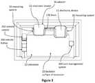
- FIG. 3illustrates a front view of an embodiment of the system, according to some embodiments.
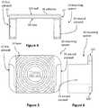
- FIG. 4illustrates a top view of an embodiment of a mounting system, according to some embodiments.
- FIG. 5illustrates a front view of an embodiment of a mounting system, according to some embodiments.
- FIG. 6illustrates a right side view of an embodiment of a mounting system, according to some embodiments.
- FIG. 7illustrates a front view of an embodiment of a mounting system, according to some embodiments.
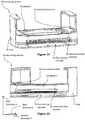
- FIG. 8illustrates a cross-sectional view along line B-B from FIG. 7 , according to some embodiments.
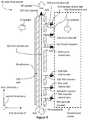
- FIG. 9illustrates a slice-sectional view along line B-B from FIG. 7 , according to some embodiments.
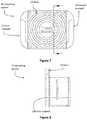
- FIG. 10illustrates a front perspective view of an embodiment of the mounting system, according to some embodiments.
- FIG. 11illustrates a back perspective view of an embodiment of the mounting system, according to some embodiments.
- FIG. 12illustrates a top perspective view of an embodiment of the mounting system, according to some embodiments.
- FIG. 13illustrates a front view of an embodiment of the mounting system, according to some embodiments.
- FIG. 14illustrates a first top perspective view of an embodiment of the mounting system, according to some embodiments.
- FIG. 15illustrates a second top perspective view of an embodiment of the mounting system, according to some embodiments.
- FIG. 16illustrates a front view of an embodiment of the system, according to some embodiments.
- FIG. 17 aillustrates a first kit embodiment and a second kit embodiment, according to various embodiments.
- FIG. 17 billustrates a third kit embodiment, according to various embodiments.
- FIG. 17 cillustrates a fourth kit embodiment, according to various embodiments.
- FIG. 18illustrates a diagrammatic view of methods, according to some embodiments.
- FIG. 19illustrates a side view of an embodiment of a hook, according to some embodiments.
- FIG. 20illustrates a first front perspective view of an embodiment of a mounting system, according to some embodiments.
- FIG. 21illustrates a second front perspective view of an embodiment of a mounting system, according to some embodiments.
- FIG. 22illustrates a top perspective view of an embodiment of a mounting system, according to some embodiments.
- FIG. 23illustrates a first side perspective view of an embodiment of a mounting system, according to some embodiments.
- FIG. 24illustrates a second side perspective view of an embodiment of a mounting system, according to some embodiments.
- FIGS. 25 and 26illustrate front views of embodiments of mounting systems, according to some embodiments.
- FIG. 27illustrates a cross-sectional view along line D-D from FIG. 25 with first and second extension walls in an extended position, according to some embodiments.
- FIG. 28illustrates detailed view E from FIG. 27 , according to some embodiments.
- FIG. 29illustrates a cross-sectional view along line D-D from FIG. 25 with first and second extension walls in a retracted position, according to some embodiments.
- FIG. 30illustrates detailed view E from FIG. 29 , according to some embodiments.
- FIG. 31illustrates an exploded bottom perspective view of a mounting system, according to some embodiments.
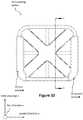
- FIG. 32illustrates a front view of an embodiment of a mounting system, according to some embodiments.
- FIG. 33illustrates a cross-sectional view along line C-C from FIG. 32 , according to some embodiments.
- FIG. 34illustrates a diagrammatic view of methods, according to some embodiments
- Electronic devicesinclude many types of devices that send content (e.g., movies, TV shows) to televisions.
- Electronic devicescan include Digital Video Disc (DVD) players, Blu-ray players, digital media extenders, and digital media players such as Apple TV (made by Apple, Inc.), Roku players (made by Roku, Inc.), and Amazon Fire TV (made by Amazon.com, Inc.).
- DVDDigital Video Disc
- Blu-ray playersBlu-ray players
- digital media extendersdigital media players
- digital media playerssuch as Apple TV (made by Apple, Inc.), Roku players (made by Roku, Inc.), and Amazon Fire TV (made by Amazon.com, Inc.).
- Digital media playersoften transmit digital signals wirelessly or through a wire such as a High-Definition Multimedia Interface (HDMI) cable to a screen that displays an image based on the digital signal.
- Screensinclude computer monitors, televisions, and image-producing portions of movie projectors.
- Televisionsinclude flat-panel displays, flat-screen televisions, and tube televisions.
- Owners of digital media playersmay prefer to mount their digital media players near their screens. For example, a person who owns a flat screen television that is mounted on the wall might want to mount her Apple TV onto her flat screen television or onto the wall behind her flat screen television. Some embodiments described herein enable people to mount their digital media players to their televisions (e.g., to a backside of a television).
- This indexprovides general information that is applicable to some embodiments, but is not necessarily applicable to all embodiments. Some embodiments use different numbers and/or descriptions than are shown in this index.
- the disclosureincludes various mounting systems 10 for mounting electronic devices 11 (e.g. digital media players) to various surfaces (e.g. a backside surface of a television 13 , a wall of a building, etc.).
- a mounting system 10is configurable to couple an electronic device 11 to a television 13 .
- the mounting system 10can include a base 14 configured to hold the electronic device 11 such that a portion of the base 14 is located between the television 13 and the electronic device 11 .
- the base 14comprises and a top portion 34 and a bottom portion 36 .
- the mounting system 10comprises a first sidewall 22 and a second sidewall 24 that extend outward away from the base 14 . As illustrated in FIGS. 4 and 5 , the first sidewall 22 and the second sidewall 24 can be located at opposite sides of the base 14 .
- the mounting systems 10can also be coupled to walls (e.g., a wall of an electronic display such as a television 13 ) via adhesive 38 , such as adhesive pads made by 3 M Company, which has offices in St. Paul, Minn.
- the mounting systems 10can also be coupled to walls and various surfaces via screws (not shown) and hooks 236 (as shown in FIG. 19 ).
- the mounting systems 10 described hereincan use the hooks 236 as described in U.S. Provisional patent application Ser. No. 14/169,148.
- the mounting systems 10can be molded from acrylonitrile butadiene styrene (“ABS”). In some embodiments, surfaces of the mounting systems 10 that may touch portions of the electronic device 11 (e.g. media player) are overmolded with a softer material, which can be a thermoplastic elastomer (“TPE”).
- ABSacrylonitrile butadiene styrene
- TPEthermoplastic elastomer
- mounting systems 10can include at least one channel that passes through an internal portion of the mounting system 10 to thereby provide airflow to the electronic device 11 .
- the channelscan allow air to flow to the electronic device 11 to prevent the electronic device 11 from getting too hot during use.
- mounting systems 10can include a first channel 520 located between a first wall 22 and a second wall 24 of the base 14 and a second channel 524 in fluid communication with the first channel 520 .
- the first channel 520can continue along a third direction Z from the bottom portion 36 to the top portion 34 of the base 14 .
- the second channel 524can extend outward from the first channel 520 such that the second channel 524 fluidly couples the first channel 520 with a portion of the mounting system 10 configured to hold the electronic device 11 .
- the second channel 524can extend along a first direction X.
- FIG. 9illustrates outward direction 55 and inward direction 57 (as indicated by the arrows in FIG. 9 ).
- the outward direction 55is away from the adhesive 38 towards a portion of the mounting system 10 configured to hold an electronic device 11 .
- the inward direction 57is away from the adhesive 38 and is opposite to the outward direction 55 .
- the outward direction 55is away from a surface to which the mounting system 10 is coupled (e.g., via the adhesive 38 ).
- the inward direction 57is towards the surface to which the mounting system 10 is coupled. In the context of FIG. 3 , the inward direction 57 is towards the television 13 and the outward direction 55 is away from the television 13 .
- FIG. 9illustrates a downward direction 58 , which is perpendicular to the outward direction 55 .
- FIG. 9also illustrates an upward direction 59 , which is perpendicular to the outward direction 55 .
- the first channel 520extends from a first opening 521 (that faces upward) to second opening 523 (that faces downward).
- the vertical dashed arrow in FIG. 9indicates the first ventilation channel 520 .
- the horizontal (outward) dashed arrows in FIG. 9indicate ventilation channels 524 , 528 , 532 , 536 , 540 , 544 that face outward, are in fluid communication with the first ventilation channel 520 , and are in fluid communication with a portion of the mounting system 10 that holds the electronic device 11 .
- FIGS. 4 and 9illustrates an anchor wall 533 oriented parallel to the base (and within plus or minus 30 degrees of parallel to the base) and coupled to the base 14 (labeled in FIG. 4 ) by at least one connecting protrusion 27 that protrudes inward from the base 14 to the anchor wall 533 .
- An adhesive 38is coupled to the anchor wall 533 and is configured to couple the mounting system 10 to a wall, such as the wall of a television 13 (shown in FIG. 3 ).
- an “anchor wall”is a wall having adhesive 38 that is used to couple the mounting system 10 to a mounting surface.
- the anchor wall 533can be molded plastic.
- Adhesive 38can be bonded to the anchor wall 533 .
- the mounting system 10comprises an outward direction 55 , a first opening (e.g. 525 or 527 ) and a second opening (e.g., 521 or 523 ).
- the first opening (e.g. 525 or 527 )faces outward
- the second opening (e.g., 521 or 523 )faces perpendicular to the outward direction
- the first ventilation channel 520 and the second ventilation channel (e.g., 524 or 532 )fluidly couple the first opening (e.g. 525 or 527 ) to the second opening (e.g., 521 or 523 ) such that the mounting system 10 is configured to enable air heated by the electronic device 11 to enter the first opening (e.g.
- the first channel 520continues from a bottom portion 36 of the base 14 to a top portion 34 of the base 14 .
- the bottom portion 36can include a first open end configured to provide access to electrical ports of the electronic device 11
- the top portion 36can include a second open end.
- Some embodimentscan also include a third channel 528 in fluid communication with the first channel 520 .
- the third channel 528can extend outward from the first channel 520 such that the third channel 528 fluidly couples the first channel 520 with the portion of the mounting system 10 configured to hold the electronic device 11 .
- the third channel 528can extend along the first direction X.
- the mounting system 10can further comprise an adhesive 38 configured to couple the base 14 to the television 13 .
- the adhesive 38is coupled to the base 14 via one or more legs 56 .
- the one or more legs 56can extend along the first direction X to thereby offset the adhesive 38 from the base 14 .
- the mounting system 10can include any number of legs 56 , such as one, two, three, four, and even five or more legs 56 .
- the first channel 520is located between the adhesive 38 and the base 14 along the first direction X. As well, the first channel 520 can be located between the one or more legs 56 and the base 14 along the first direction X. In some embodiments, the first channel 520 is located between the adhesive 38 and the first wall 22 along the first direction X. Even still, in some embodiments, the first channel 520 is located between the adhesive 38 and the second wall 24 along the first direction X.
- the mounting system 10can dispose the first channel 520 at various locations along the first direction X.
- the first channel 520can be located between the adhesive 38 and the electronic device 11 .
- the first channel 520can be located between the base 14 and the electronic device 11 along the first direction X.
- the mounting system 10can include additional channels.
- some mounting systems 10can include a fourth channel 532 in fluid communication with the first channel 520 .
- the fourth channel 532can extend outward from the first channel 520 such that the fourth channel 532 fluidly couples the first channel 520 with the portion of the mounting system 10 configured to hold the electronic device 11 .
- the fourth channel 532can extend along a fourth central axis 534 , which can extend along the first direction X.
- some mounting systems 10can include a fifth channel 536 in fluid communication with the first channel 520 .
- the fifth channel 536can extend outward from the first channel 520 such that the fifth channel 536 fluidly couples the first channel 520 with the portion of the mounting system 10 configured to hold the electronic device 11 .
- the fifth channel 536can extend along a fifth central axis 538 , which can extend along the first direction X.
- some mounting systems 10can even include a sixth channel 540 in fluid communication with the first channel 520 .
- the sixth channel 540can extend outward from the first channel 520 such that the sixth channel 540 fluidly couples the first channel 520 with the portion of the mounting system 10 configured to hold the electronic device 11 .
- the sixth channel 540can extend along a sixth central axis 542 , which can extend along the first direction X.
- Some mounting systems 10can even include a seventh channel 544 in fluid communication with the first channel 520 .
- the seventh channel 544can extend outward from the first channel 520 such that the seventh channel 544 fluidly couples the first channel 520 with the portion of the mounting system 10 configured to hold the electronic device 11 .
- the seventh channel 544can extend along a seventh central axis 546 , which can extend along the first direction X.
- the fourth channel 532can be substantially parallel to at least one of the fifth channel 536 , the sixth channel 540 , and the seventh channel 544 .
- the fourth channel 532is substantially parallel to the fifth channel 536
- the fifth channel 536is substantially parallel to the sixth channel 540
- the sixth channel 540is substantially parallel to the seventh channel 544 .
- the first channel 520can extend from a top opening to a bottom opening of the base 14 .
- the top opening and the bottom openingare located between the first wall 22 and the second wall 24 of the base 14 .
- the first channel 520 and the additional channelscan be disposed in various locations along the mounting system 10 .
- the first channel 520 and any additional channelscan be configured to provide airflow to specific locations of the electronic device 11 , when the electronic device 11 is coupled to the mounting system 10 .
- the second, third, fourth, fifth, sixth, and/or seventh channel 524 , 528 , 532 , 536 , 540 , 544can be disposed at any angle with respect to the first channel 520 .
- the second, third, fourth, fifth, sixth, and/or seventh channel 524 , 528 , 532 , 536 , 540 , 544can be disposed at angles that allow the various channels to be aimed at specific locations on the electronic device 11 .
- the second, third, fourth, fifth, sixth, and/or seventh channel 524 , 528 , 532 , 536 , 540 , 544are disposed perpendicular with respect to the first channel 520 .
- the second, third, fourth, fifth, sixth, and/or seventh channel 524 , 528 , 532 , 536 , 540 , 544are not perpendicular with respect to the first channel 520 .
- a first central axis 522 of the first channel 520can be within plus or minus twenty degrees of a plane of the adhesive 38 .
- the second channel 524 and the third channel 528can be within plus or minus forty degrees of being perpendicular to the first central axis 522 of the first channel 520 .
- a second central axis 526 of the second channel 524can be within plus or minus thirty degrees of a third central axis 530 of the third channel 528 .
- the third central axis 530 of the third channel 528is substantially parallel to the second central axis 526 of the second channel 524 .
- mounting systems 10can be configured to accommodate electronic devices 11 of different sizes, such as electronic devices 11 of different thicknesses.
- a mounting system 10is configurable to couple an electronic device (e.g. a streaming media player, gaming console, cable box, and the like) to a television 13 .
- the mounting system 10can be attached to any surface, such as a wall or television 13 (e.g. a backside surface of a television 13 ). As shown in FIG. 11 , the mounting system 10 can include various attachment features. In some embodiments, the mounting system 10 includes at least one hook hole 40 , at least one screw hole 42 , and/or an adhesive (e.g. an adhesive pad 38 ) located along a backside of the base 14 . A first side of the adhesive pad 38 can be adhesively attached to the backside of the base 14 , while the second side of the adhesive pad 38 , which is opposite the first side of the adhesive pad 38 , can be adhesively attached to any surface, such as a backside of the television 13 , and the like.
- an adhesivee.g. an adhesive pad 38
- the adhesive pad 38is about 1 millimeter thick. In some embodiments, the adhesive pad 38 is about 0.045 inches thick. Generally, it should be appreciated that the adhesive pad 38 can define any thickness greater than 0.045 inches, or any thickness less than 0.045 inches.
- the at least one hook hole 40can be configured to receive a first end of a hook 236 (as shown in FIG. 17 ), such as the hooks described in U.S. patent application Ser. No. 13/278,759, filed Oct. 21, 2011, and entitled MOUNTING SYSTEM FOR DIGITAL MEDIA PLAYERS. The entire contents of U.S. patent application Ser. No. 13/278,759 are incorporated by reference herein.
- a second end of the hook 236can thereby engage an opening along the television 13 , such as an air vent located along a backside of the television 13 , to thereby couple the mounting system 10 to the television 13 .
- the screw hole 42can be an aperture that receives a screw, which can be threadably attached to a surface, such as a wall or television 13 , to thereby attach the mounting system 10 to the surface.
- the mounting system 10can include a base 14 configured to hold the electronic device 11 .
- the mounting system 10can include a first sidewall 22 that extends from a first side of the base 14 along a first direction X that points away from the television 13 .
- the mounting system 10can also include a second sidewall 24 that extends from a second side of the base 14 along the first direction X. It should be appreciated that the first side can be opposite the second side.
- the second sidewall 24can be spaced from the first sidewall 22 along a second direction Y that is perpendicular to the first direction X.
- the mounting system 10can include an adapter 16 received (e.g. removably coupled) between the first sidewall 22 and the second sidewall 24 .
- the adapter 16can be slideably received by the tray 12 along a third direction Z that is perpendicular to the first direction X and the second direction Y.
- the tray 12can receive the adapter along a mating direction, other than the third direction Z, such as the first direction X or even the second direction Y.
- the tray 12can include a top portion 34 and a bottom portion 36 that is located opposite the top portion 34 .
- the top portion 34can be spaced from the bottom portion 36 along a third direction Z that is perpendicular to the first direction X and the second direction Y.
- the first sidewall 22extends from the top portion 34 to the bottom portion 36 of the tray 12
- the second sidewall 24extends from the top portion 34 to the bottom portion 36 of the tray 12
- the first sidewall 22 and the second sidewall 24can be configured to slideably receive the electronic device 11 at the top portion 34 of the tray 12
- the first sidewall 22 and the second sidewall 24can be configured to retain the electronic device 11 at the bottom portion 36 of the base 14 .
- a bottom portion of the first sidewall 22 and a bottom portion of the second sidewall 24can curve inward such that the bottom portion of the first sidewall 22 faces the bottom portion of the second sidewall 24 to thereby retain the electronic device 11 from moving along the third direction Z.
- Portions of the first and second sidewalls 22 , 24can also extend along the second direction Y to provide additional support for retaining (i.e. securing) the electronic device 11 .
- a portion of the first sidewall 22extends along the second direction Y towards the second sidewall 24 .
- a portion of the second sidewall 24can extend along the second direction Y towards the first sidewall 22 . In this manner, the portions of the first and second sidewalls 22 , 24 can wrap around a surface of the electronic device 11 .
- the first sidewall 22 and the second sidewall 24are located along at least one of a top portion 34 of the tray 12 and a bottom portion 36 of the tray 12 .
- the first sidewall 22 and/or the second sidewall 24are elongate along the third direction Z whereby the first and second sidewalls 22 , 24 continuously extend from the top portion 34 to the bottom portion 36 of the tray 12 .
- a portion of the first sidewall 22 and a portion of the second sidewall 24each can be disposed along a middle portion of the tray 12 that is located between a top portion 34 and a bottom portion 36 of the tray 12 .
- first and second sidewalls 22 , 24are not continuous between the top portion 34 and the bottom portion 36 .
- the first sidewall 22 and the second sidewall 24might each comprise one or more segments that are not adjoined along the third direction Z.
- the first sidewall 22 and the second sidewall 24might each contain one or more posts to retain the electronic device 11 and the adapter 16 .
- the first sidewall and the second sidewallcan be configured to receive a first electronic device having a first thickness.
- the first sidewall and the second sidewallcan be configured to simultaneously receive a second electronic device having a second thickness and the adapter having a third thickness.
- the first thicknessis greater than the second thickness.
- the first thicknessis substantially equal to the second thickness plus the third thickness.
- the first thicknessis about 1.4 inches thick
- the second thicknessis about 0.9 inches thick
- the third thicknessis about 0.5 inches thick.
- the electronic device 11can define a length of about 3.9 inches and a width of about 3.9 inches.
- the adapter 16can be coupled to or removed from the mounting system 10 to thereby accommodate different thickness electronic devices 11 .
- the adapter 16can be removed from the mounting system 10 to thereby allow thicker electronic devices 11 having a first thickness to securely fit between the base 14 and the first and second walls 22 , 24 of the mounting system 10 .
- thinner electronic devices 11 having a second thicknessmay securely fit between the base 14 and the first and second sidewalls 22 , 24 of the mounting system 10 .
- the adapterallows the thicker and thinner electronic devices 11 to be securely fit with respect to the first direction X. In other words, the electronic devices will be substantially fixed with respect to the first direction X.
- the first thicknessis greater than the second thickness. In some embodiments, the first thickness is 0.5 inches thicker than the second thickness. In some embodiments, the first thickness is less than 0.5 inches thicker than the second thickness, while in some embodiments, the first thickness is greater than 0.5 inches thicker than the second thickness.
- the first sidewall 22 and the second sidewall 24can include various features to securely retain the adapter 16 in place within the mounting system 10 .
- the mounting system 10can include a first inward protrusion 26 a that extends from an inward surface (or inner periphery 32 ) of the first sidewall 22 , and a second inward protrusion 26 b that extends from an inward surface (or inner periphery 32 ) of the second sidewall 24 .
- the first inward protrusion 26 a and the second inward protrusion 26 bcan extend along the second direction Y.
- first inward protrusion 26 a and the second inward protrusion 26 bextend toward each other along the second direction Y.
- first inward protrusion 26 acan face the second inward protrusion 26 b.
- the first sidewall 22 and the second sidewall 24can be configured to receive a first electronic device 11 a having a first thickness.
- the first sidewall 22 and the second sidewall 24can be configured to receive both a second electronic device 11 b having a second thickness and the adapter having a third thickness. In this manner, the first thickness can be greater than the second thickness. As well, the first thickness can be substantially equal to the second thickness plus the third thickness.
- the first inward protrusion 26 a and the second inward protrusion 26 bcan securely retain the adapter 16 along the first direction X. Described differently, the first and second inward protrusions 26 a , 26 b can substantially fix the adapter 16 with respect to the first direction X.
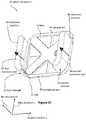
- the adapter 16comprises a large ventilation channel 18 that extends through the adapter 16 along the first direction X.
- the large ventilation channel 18can provide air flow to a surface of the electronic device 11 to thereby regulate or maintain a temperature of the electronic device 11 .
- the large ventilation channel 18can be elongate along the second direction Y and the third direction Z.
- the large ventilation channel 18can define any shape, such as round, rectangular, and the like.
- the adapter 16can comprise at least one small ventilation channel 20 that extends through the adapter 16 along the first direction X.
- the large ventilation channel 18is at least partially surrounded by the at least one small ventilation channel 20 . As such, a center point or location of the base 14 can be located within the large ventilation channel 18 .
- the large ventilation channel 18 and the small ventilation channel 20can be located in opposite positions with respect to one another, as previously described.
- the at least one small ventilation channel 20can be at least partially surrounded by the large ventilation channel 18 .
- a center location of the base 14can be located within the small ventilation channel 20 .
- the adapter 16can be configured to fit in a variety of ways within the mounting system 10 . In some embodiments, when the electronic device 11 is coupled to the mounting system 10 a portion of the adapter 16 can be located between the television 13 and the electronic device 11 . As well, in some embodiments, when the electronic device 11 is coupled to the mounting system 10 , the electronic device 11 can be located between the base 14 and a portion of the adapter 16 .
- the tray 12can comprise an outward facing periphery 30 and an inward facing periphery 31 that is opposite the outward facing periphery 30 .
- the outward facing periphery 30can comprise an outer surface that faces away from the electronic device 11 .
- the inward facing periphery 32can define an inner surface that faces towards the electronic device 11 .
- portions of the adapter 16can be arranged and configured to align with portions of the outward facing periphery 30 and the inward facing periphery 32 . For example, as shown in FIG.
- a top portion of the outer periphery 32 of the adapter 16can be substantially aligned (along the first direction X) with a top portion of the outward facing periphery 30 of the tray 12 .
- a bottom portion of the outer periphery 32 of the adapter 16can be substantially aligned (along the first direction X) with a bottom portion of the outward facing periphery 30 of the tray 12 .
- the outward facing periphery 30 of the tray 12can define a first footprint of the mounting system 10 .
- the mounting system 10can define a second footprint.
- the first footprintis substantially aligned (along the first direction X) with the second footprint.
- the first footprintis not substantially aligned (along the first direction X) with the second footprint.
- the anchor wall 533is rigidly coupled to the base 14 by connecting protrusions 27 .
- the mounting system 10comprises an adapter 16 slideably received by the base 14 between the first sidewall 22 and the second sidewall 24 .
- FIG. 10illustrates an exploded view with the adapter 16 slid out of the base 14 .
- the adapter 16comprises an aperture 18 configured to be in fluid communication with the first ventilation channel 50 and the second ventilation channel 54 .
- FIGS. 14 and 15illustrate the adapter 16 slid into mounting system 10 such that the aperture 18 is in fluid communication with the first ventilation channel 50 and the second ventilation channel 54 .
- the inner periphery 31 of the adapter 16can be arranged and configured to fit within the inward facing periphery 31 of the tray 12 . As such, the adapter 16 can be slideably received by the tray 12 .
- the inner periphery 31is dimensionally sized such that the adapter 16 easily slides into the tray 12 . “Easily” can be defined as requiring minimal force or effort by a human hand, almost effortless.
- the inner periphery 31is dimensionally sized such that the adapter 16 frictionally slides into the tray 12 .
- This arrangementcan be used in various embodiments where the mounting system 10 is oriented such that a friction fit between the adapter 16 and tray 12 is required in order to retain the adapter 16 within the tray 12 .
- this configurationcan be used in embodiments where the mating direction to couple the adapter 16 to the tray 12 is along another direction, such as the first direction X.
- embodiments of the mounting system 10can even include an electronic device 11 , such as a streaming media player 11 .
- the mounting system 10can include a television 13 communicatively coupled to the streaming media player 11 .
- the mounting system 10can even include a HDMI cable 70 having a first end coupled to the streaming media player 11 and a second end coupled to the television 13 .
- the HDMI cable 70can be configured to transmit digital signals between the streaming media player 11 and the television 13 .
- the mounting system 10can include a power cable 72 having a first end coupled to the streaming media player 11 and a second end coupled to one of the television 13 and a wall outlet 74 .
- the power cable 72can be configured to transmit electricity from one of the television 13 and the wall outlet 74 to the streaming media player 11 .
- a first kit 78can include the electronic device 11 (such as a streaming media player and/or gaming console), a tray 12 configurable to couple the electronic device 11 to the television 13 , and an adapter 16 that can be slideably received by the tray 12 .
- the tray 12can also be referred to as a mount 12 .
- the first kitcan also include an HDMI cable 70 that can be communicatively coupled with the electronic device 11 and a television 13 , a power cable 72 that can be electrically coupled to the electronic device 11 to thereby supply power, a remote holder 200 (such as the remote holders disclosed in U.S. Provisional Patent Applications 62/242,988 and 62/243,722), and a remote control 202 that can be communicatively coupled to the electronic device 11 and/or television 13 .
- the first kit 78can even include a remote control charging cable 73 that can be electrically coupled to the remote control 202 , a hook 236 that can securely couple the tray 12 to the television 13 , a gaming controller 85 configurable to be communicatively coupled to the electronic device 11 (e.g.
- a second kit 80includes the components of the first kit and further includes a television 13 .
- kitsthat comprise any combination of components from the first and second kits 78 , 80 .
- the disclosureincludes a third kit 82 that comprises a tray 12 , a remote holder 200 , and a cord management system 300 .
- a fourth kit 84can include a tray 12 , adapter 16 , remote holder 200 , and cord management system 300 .
- some kitscomprise various quantities of specific components.
- a kitcomprises one tray 12 , one remote holder 200 , and two cord management systems 300 .
- the disclosurealso includes other kits, not shown in FIGS. 17 a -17 c .
- the disclosureincludes a fifth kit comprising the electronic device 11 , tray 12 , adapter 16 , and HDMI cable 70 .
- the disclosurealso includes a sixth kit comprising the tray 12 , adapter 16 , and HDMI cable 70 .
- the disclosureincludes a seventh kit comprising the electronic device 11 , tray 12 , and adapter 16 .
- the disclosureincludes an eighth kit comprising the tray 12 , adapter 16 , HDMI cable 70 and/or the power cable 72 .
- the disclosureincludes any combination of components as illustrated in FIG. 17 a.
- the electronic device 11is a first electronic device 11 a having a first thickness.
- the adapter 16can be slideably received by the mount 12 whereby the adapter 16 allows the mount 12 to securely receive a second electronic device 11 b having second thickness that is less than the first thickness.
- the tray 12comprises adhesive 38 configurable to couple the electronic device 11 to a backside of the television 13 .
- the remote holder 200can include adhesive configurable to couple the electronic device 11 to at least one of a side of the television 13 and the backside of the television.
- the cord management system 300can also comprise adhesive configurable to couple the cord management system 300 to the television 13 , such as the backside of the television.
- the tray 12 and remote holder 200can be configured to receive various cables.
- the tray 12is configurable to receive at least one of a power cable 72 electrically coupled to the electronic device 11 and an HDMI cable 70 communicatively coupled to the electronic device 11 .
- the remote holder 200can be configurable to receive a charging cable 73 such that when the remote holder 200 receives the remote control 202 the charging cable 73 electrically couples with the remote control 202 .
- Embodiments of the mounting system 10can be configured to receive different size electronic devices 11 .
- mounting systems 10can include height adjustable sidewalls that can be configured to receive electronic devices 11 of varying thicknesses or heights.
- the mounting system 10can include a base 14 configured to hold the electronic device 11 such that a portion of the base 14 is located between the television 13 and the electronic device 11 .
- the base 14can comprise a first sidewall 22 and a second sidewall 24 .
- mounting systemscan also include retaining lips 25 coupled to the first sidewall 22 and the second sidewall 24 . The retaining lips 25 can be configured to impede the electronic device 11 from falling out of the base 14 .
- a mounting system 10can be configurable to couple an electronic device 11 to a television 13 .
- the mounting system 10can include a base 14 configured to hold the electronic device 11 .
- the mounting system 10also includes a first sidewall 22 that extends from the base 14 along a first direction X that points away from the television 13 and a second sidewall 24 that extends from the base 14 along the first direction X, wherein the second sidewall 24 is spaced from the first sidewall 22 along a second direction Y that is perpendicular to the first direction X.
- FIG. 33illustrates outward direction 55 and inward direction 57 (as indicated by the arrows in FIG. 33 ).
- the outward direction 55is away from the adhesive 38 towards a portion of the mounting system 10 configured to hold an electronic device 11 .
- the inward direction 57is away from the adhesive 38 and is opposite relative to the outward direction 55 .
- the outward direction 55is away from a surface to which the mounting system 10 is coupled (e.g., via the adhesive 38 ).
- the inward direction 57is towards the surface to which the mounting system 10 is coupled. In the context of FIG. 3 , the inward direction 57 is towards the television 13 and the outward direction 55 is away from the television 13 .
- FIG. 33illustrates a downward direction 58 , which is perpendicular to the outward direction 55 .
- FIG. 33also illustrates an upward direction 59 , which is perpendicular to the outward direction 55 .
- the first channel 520extends from a first opening 521 (that faces upward) to second opening 523 (that faces downward).
- the vertical dashed arrow in FIG. 33indicates the first ventilation channel 520 .
- the horizontal (outward) dashed arrows in FIG. 33indicate ventilation channels 524 , 528 that face outward, are in fluid communication with the first ventilation channel 520 , and are in fluid communication with a portion of the mounting system 10 that holds the electronic device 11 .
- the mounting system 10comprises an outward direction 55 , a first opening (e.g. 525 or 527 ) and a second opening (e.g., 521 or 523 ).
- the first opening (e.g. 525 or 527 )faces outward
- the second opening (e.g., 521 or 523 )faces perpendicular to the outward direction 55
- the first ventilation channel 520 and the second ventilation channel (e.g., 524 or 528 )fluidly couple the first opening (e.g. 525 or 527 ) to the second opening (e.g., 521 or 523 ) such that the mounting system 10 is configured to enable air heated by the electronic device 11 to enter the first opening (e.g.
- the baseis hidden.
- the interior of the side wallscan be overmolded with a material (e.g., a thermoplastic elastomer) that is softer than the material (e.g., ABS) that is used to mold other elements.
- Protrusionsthat enable the sidewalls to lock in upwards or downward positions
- embodiments of the mounting system 10also include a first extension wall 92 slideably coupled to the first sidewall 22 and a second extension wall 94 slideably coupled to the second sidewall 24 .
- the first extension wall 92moves with respect to the first sidewall 22 along the first direction X.
- the second extension wall 94moves with respect to the second sidewall 24 along the first direction X. In this manner, the first and second extension walls 92 , 94 can move between a retracted position 86 (or an inward locked position 86 ), as shown in FIGS. 20 and 21 , and an extended position 88 (or an outward locked position 88 ), as shown in FIG.
- the first extension wall 92moves with respect to the first sidewall 22 along both the first direction X and the second direction Y.
- the second extension wall 94moves with respect to the second sidewall 24 along both the first direction X and the second direction Y.
- a first electronic device 11 a having a first thicknesscan be securely coupled to the mounting system 10 .
- thicknesse.g. first thickness and second thickness
- first thickness and second thicknesscan define the height of the electronic device along the first direction X.
- first thicknessis greater than the second thickness.
- first and second extension walls 92 , 94when the first and second extension walls 92 , 94 are in the extended position 88 , thicker electronic devices 11 can be securely coupled between the first and second extension walls 92 , 94 . As such, when the first and second extension walls 92 , 94 are in the retracted position 86 , thinner electronic devices 11 can be securely coupled between the first and second extension walls 92 , 94 .
- the first thicknessis about 1.4 inches. In some embodiments, the second thickness is about 0.9 inches.
- “securely coupled”means snugly fit or closely fit.
- “securely coupled”can mean that the inside space between the base and a top underside of the extension wall is slightly greater than the thickness (e.g. height) of the electronic device 11 .
- the thickness of a first electronic deviceis 1.4 inches
- the inside space of the first and second extension walls 92 , 94can be a distance slightly greater than 1.4 inches, e.g. 1.45 inches, 1.5 inches, or even 1.6 inches.
- the inside space of the first and second extension walls 92 , 94can be slightly greater than 0.9 inches, e.g. 0.95 inches, 1.0 inches, or even 1.1 inches.
- FIG. 22illustrates anchor walls 533 oriented parallel to the base 14 (and within plus or minus 30 degrees of parallel to the base) and coupled to the base 14 (labeled in FIG. 4 ) by at least one connecting protrusion 56 (shown in FIG. 33 ) that protrudes inward from the base 14 to the anchor wall 533 .
- the connecting protrusion 56comprises a flexible neck (e.g., flexible neck 42 , 52 , 92 , 124 , 154 , 158 as shown in FIG. 4 of U.S. patent application Ser. No. 14/572,293; filed Dec. 16, 2014; and entitled MOUNTING SYSTEMS FOR ELECTRONIC DEVICES).
- the entire contents of U.S. patent application Ser. No. 14/572,293are incorporated by reference herein.
- the flexible neckcan enable the anchor wall 533 to be a foot 174 , 176 , 200 , 206 , 202 , 204 configured to enable the adhesive to pivot and move relative to the base as explained in U.S. patent application Ser. No. 14/572,293 (e.g., as shown in FIG. 4 ).
- an adhesive 38is coupled to the anchor wall 533 and is configured to couple the mounting system 10 to a wall, such as the wall of a television 13 (shown in FIG. 3 ).
- the adhesive 38can pivot and move relative to the base 14 due to flexible necks.
- an “anchor wall”is a wall having adhesive that is used to couple the mounting system to a mounting surface.
- the anchor wall 533can be molded plastic.
- Adhesive 38can be bonded to the anchor wall 533 .
- a bottom portion of the first sidewall 22 and a bottom portion of the second sidewall 24can curve inward such that the bottom portion of the first sidewall 22 can face the bottom portion of the second sidewall 24 .
- the first extension wall 92can include a first retaining lip 25 that extends from a top portion to a bottom portion of the first extension wall 92 .
- the second extension wall 94can include a second retaining lip 25 that extends from a top portion to a bottom portion of the second extension wall 94 .
- the first and second retaining lips 25can thereby be configured to fix the electronic device 11 to the base 14 along the first direction X.
- the first extension wall 92comprises a first retention portion 25 that faces away from the first sidewall 22 and the second extension wall 94 comprises a second retention 25 portion that faces away from the second sidewall 24 .
- the first retention portion 25can be located a first distance from the base 14 .
- the first retention portion 25can be located a second distance from the base 14 .
- the second retention portion 25can be located a third distance from the base 14 .
- the second retention portion 25can be located a fourth distance from the base 14 .
- the first distanceis greater than the second distance and the third distance is greater than the fourth distance.
- the movement of the first and second extension walls 92 , 94 , and therefore the first and second retention portions 25 , along the first direction Xcan thereby allow the mounting system 10 to securely couple to electronic devices 11 of various thicknesses (e.g. heights).
- the extension walls 92 , 94can thereby be locked into place.
- the first extension wall 92when the first extension wall 92 is in the retracted position 86 and/or extended position 88 , the first extension wall 92 can be locked in place relative to the first sidewall 22 and/or the base 14 .
- the second extension wall 94when the second extension wall 94 is in the retracted position 86 and/or extended position 88 , the second extension wall 94 can be locked in place relative to the second sidewall 24 and/or the base 14 .
- some embodiments of the mounting system 10can further include a first engaging portion 106 located along a portion of the first extension wall 92 and a second engaging portion 112 located along a portion of the second extension wall 94 .
- embodiments of the mounting system 10can include a first retraction slot 102 located along an outer surface of the first sidewall 22 .
- the first retraction slot 102can be configured to receive the first engaging portion 106 when the first extension wall 92 is in the retracted position 86 .
- some embodiments of the mounting system 10can include a second retraction slot 108 located along an outer surface of the second sidewall 24 .
- the second retraction slot 108can be configured to receive the second engaging portion 112 when the second extension wall 94 is in the retracted position 86 .
- the slotscan be indentation in a first sidewall (e.g., as shown in FIG. 28 ).
- the first sidewallcan be coupled to a second sidewall configured to move inward and outward relative to the first sidewall.
- the second sidewallcan include a protrusion oriented towards the indentations to releasably snap into an indentation.
- the systemcan include one indentation located outward from a second indentation. These two indentations can form a first locking mechanism.
- the systemcan include a second identical locking mechanism.
- the first locking mechanismcan be located on an upper portion of the sidewall system and the second locking mechanism can be located on a lower portion of the sidewall system.
- the first engaging portion 106can lock with the first retraction slot 102 to thereby lock the first extension wall 92 with respect to the first sidewall 22 and/or the base 14 .
- the second engaging portion 112can lock with the second retraction slot 108 to thereby lock the second extension wall 94 with respect to the second sidewall 24 and/or the base 14 .
- Mounting systems 10can also include a first extension slot 104 located along the outer surface of the first sidewall 22 .
- the first extension slot 104can be located further from the base 14 than the first retraction slot 102 .
- the first extension slot 104can be configured to receive the first engaging portion 106 when the first extension wall 92 is in the extended position 88 .
- some embodiments of the mounting systems 10can also include a second extension slot 110 located along the outer surface of the second sidewall 24 .
- the second extension slot 110can be located further from the base 14 than the second retraction slot 108 .
- the second extension slot 110can be configured to receive the second engaging portion 112 when the second extension wall 94 is in the extended position 88 .
- the first engaging portion 106can lock with the first extension slot 104 to thereby lock the first extension wall 92 with respect to the first sidewall 22 and/or the base 14 .
- the second engaging portion 112can lock with the second extension slot 110 to thereby lock the second extension wall 94 with respect to the second sidewall 24 and/or the base 14 .
- mounting systems 10can include additional slots and engaging portions to provide additional security and support between the extension walls and sidewalls.
- mounting systems 10can include a third engaging portion 118 located along the portion of the first extension wall 92 .
- the third engaging portion 118can be spaced from the first engaging portion 106 along the third direction Z that is perpendicular to the first direction X and the second direction Y.
- some mounting systems 10can include a fourth engaging portion 124 located along the portion of the second extension wall 94 .
- the fourth engaging portioncan be spaced from the second engaging portion 112 along the third direction Z.
- embodiments of the mounting system 10can include a third retraction slot 114 located along the outer surface of the first sidewall 22 .
- the third retraction slot 114can be spaced from the first retraction slot 102 along the third direction Z.
- the third retraction slot 114can thereby be configured to receive the third engaging portion 118 when the first extension wall 92 is in the retracted position 86 .
- embodiments of the mounting system 10can include a fourth retraction slot 120 located along the outer surface of the second sidewall 24 .
- the fourth retraction slot 120can be spaced from the second retraction slot 108 along the third direction Z.
- the fourth retraction slot 120can thereby be configured to receive the fourth engaging portion 124 when the second extension wall 94 is in the retracted position 86 .
- the mounting system 10can also include a third extension slot 116 located along the outer surface of the first sidewall 22 .
- the third retraction slot 114can be located closer to the base 14 than the third extension slot 116 .
- the third extension slot 116can be configured to receive the third engaging portion 118 when the first extension wall 92 is in the extended position 88 .
- Embodiments of the mounting system 10can also include a fourth extension slot 122 located along the outer surface of the second sidewall 24 .
- the fourth retraction slot 120can be located closer to the base 14 than the fourth extension slot 122 .
- the fourth extension slot 122can be configured to receive the fourth engaging portion 124 when the second extension wall 94 is in the extended position 88 .
- Embodiments of the mounting system 10can include additional features to aid in the movement of the first and second extension walls 92 , 94 between the retracted position 86 and the extended position 88 . More specifically, the additional features can help to unlock the respective engaging portions from the respective extension and/or retraction slots.
- the first retraction slot 102comprises a first ramp 414 and the second retraction slot 108 comprises a third ramp 418 . As the first engaging portion 106 slides across the first ramp 414 , the first extension wall 92 can thereby move from the retracted position 86 to the extended position 88 .
- the first ramp 414can allow the first engaging portion 106 to more easily unlock from the first retraction slot 102 when the first extension wall 92 moves from the retracted position 86 towards the extended position 88 .
- the third ramp 418can allow the second engaging portion 112 to more easily unlock from the second retraction slot 108 when the second extension wall 94 moves from the retracted position 86 towards the extended position 88 .
- the first extension slot 104can include a second ramp 416 and the second extension slot 110 can include a fourth ramp 420 .
- the first engaging portion 106slides across the second ramp 416
- the first extension wall 92moves from the extended position 88 to the retracted position 86 .
- the second engaging portion 112slides across the fourth ramp 420
- the second extension wall 94moves from the extended position 88 to the retracted position 86 .
- the second ramp 416can allow the first engaging portion 106 to more easily unlock from the first extension slot 104 when the first extension wall 92 moves from the extended position 88 towards the retracted position 86 .
- the fourth ramp 420can allow the second engaging portion 112 to more easily unlock from the second extension slot 110 when the second extension wall 94 moves from the extended position 88 towards the retracted position 86 .
- the first engaging portion 106can include a first angled surface 422 configured to slide across the second ramp 416 when the first extension wall 92 moves from the extended position 88 to the retracted position 86 .
- the second engaging portion 112can comprise a second angled surface 424 configured to slide across the fourth ramp 420 when the second extension wall 94 moves from the extended position 88 to the retracted position 86 .
- the first angled surface 422can allow the first engaging portion 106 to more easily unlock from the first extension slot 104 to thereby move the first extension wall 92 from the extended position.
- the second angled surface 424can allow the second engaging portion 112 to more easily unlock from the second extension slot 110 to thereby move the second extension wall 94 from the extended position.
- the angled surfacescan be disposed along any surface of the respective first engaging portion 106 and/or the second engaging portion 112 .
- the first angled surface 422could be disposed along an opposite facing surface, as the surface that the first angled surface 422 is disposed in FIGS. 27 and 28 . In this regard, this opposite configuration could assist the first engaging portion 106 to more easily unlock from the first retraction slot 102 to thereby move the first extension wall 92 from the retracted position 86 .
- the disclosurealso includes methods of using a tray 12 to couple an electronic device 11 to a television 13 .
- methodscan include coupling an adapter 16 between a first sidewall 22 and a second sidewall 24 of the tray 12 (at step 1800 ).
- the first and second sidewalls 22 , 24can extend away from the television 13 along a first direction X.
- Methodscan also include coupling a first electronic device 11 a between the first sidewall 22 and the second sidewall 24 of the tray 12 (at step 1802 ).
- Methodscan also include fixing the first electronic device 11 a and the adapter 16 to the tray 12 along the first direction X (at step 1804 ). Some methods can even include decoupling the first electronic device 11 a from the first sidewall 22 and the second sidewall 24 of the tray 12 (at step 1806 ). Even still, methods can include decoupling the adapter 16 from the first sidewall 22 and the second sidewall 24 of the tray 12 (at step 1808 ).
- methodscan even include coupling a second electronic device 11 b between the first sidewall 22 and the second sidewall 24 of the tray 12 (at step 1810 ).
- the first electronic device 11 ahas a first thickness extending along the first direction X.
- the second electronic device 11 bcan have a second thickness extending along the first direction X.
- the adapter 16can have a third thickness extending along the first direction X.
- the third thicknessis substantially equal to the first thickness plus the second thickness. It should be appreciated that the first, second, and third thicknesses can be equal to any size thickness.
- Some methodscan include fixing the second electronic device 11 b to the tray 12 along the first direction X (at step 1812 ). As well, methods can include positioning the tray 12 so that a portion of the tray 12 is located between the television 13 and the first electronic device 11 a (at step 1814 ). Some embodiments can include configuring the adapter 16 so that the adapter 16 is located between the television 13 and the first electronic device 11 a (at step 1816 ). Even still, some embodiments can include configuring the adapter 16 so that the first electronic device 11 a is located between the television 13 and the adapter 16 (at step 1818 ).
- Methodscan also include adhesively attaching the tray 12 to a backside surface of the television 13 (at step 1820 ).
- methodscan include communicatively coupling, by a High-Definition Multimedia Interface cable 70 , the first electronic device 11 a to the television 13 (at step 1822 ).
- the disclosurealso includes methods of using a tray 12 to couple an electronic device 11 to a television 13 .
- the tray 12can comprise a base 14 configured to hold the electronic device 11 , a first sidewall 22 , a second sidewall 24 , a first extension wall slideably coupled to the first sidewall, and a second extension wall slideably coupled to the second sidewall.
- methodscan include moving the first extension wall 92 along the first direction X (at step 3400 ).
- the first extension wall 92can move with respect to the first sidewall 22 .
- Methodscan also include moving the second extension wall 94 along the first direction X (at step 3402 ).
- the second extension wall 94moves with respect to the second sidewall (at step 3402 ).
- Methodscan also include securely coupling an electronic device 11 between the first extension wall 92 and the second extension wall 94 (at step 3404 ).
- Methodscan also include moving the first extension wall 92 from a retracted position 86 to an extended position 88 and moving the second extension wall 94 from the retracted position 86 to the extended position 88 (at step 3406 ).
- methodscan then include securely coupling a first electronic device 11 a between the first extension wall 92 and the second extension wall 94 (at step 3408 ).
- the first electronic device 11 acan define a first thickness extending along the first direction X.
- methodsinclude moving the first extension wall 92 from the extended position 86 to the retracted position 88 and moving the second extension wall 94 from the extended position 88 to the retracted position 86 (at step 3410 ). After performing step 3410 , methods can then include securely coupling a second electronic device 11 b between the first extension wall 92 and the second extension wall 94 (at step 3412 ).
- the second electronic device 11 bcan define a second thickness extending along the first direction X. In some embodiments, the first thickness is greater than the second thickness.
- Methodscan even include decoupling the first electronic device 11 a from the first extension wall 92 and the second extension wall 94 (at step 3414 ).
- methodsinclude positioning the tray 12 so that a portion of the base 14 is located between the television 13 and the electronic device 11 (at step 3416 ).
- the tray 12can further include an adhesive pad 28 attached to the base 12 .
- Methodscan also include adhesively attaching the tray 12 to a backside surface of the television 13 (at step 3418 ).
- methodscan include communicatively coupling, by an HDMI cable 70 , the electronic device 11 to the television 13 (at step 3420 ).
- the term “substantially”can be interpreted to have different meanings depending upon the context. For example, “substantially” can mean two surfaces that are within 25-degrees of each other. As well, the term “substantially” can be understood to mean that two protrusions are aligned within 0.5 inches of one another along a defined direction. In other contexts, “substantially” can mean plus or minus 0.5 inches.
- the term “about”can be interpreted to mean different things depending upon the context. For example, if the disclosure states that a pad is “about” 0.045 inches thick. The term “about” can mean that the pad is within + or ⁇ 0.005 inches. In another example, if the disclosure states that a thickness is “about” 0.5 inches thick. The term “about,” within this context, can mean that the thickness is within + or ⁇ 0.05 inches. In yet another example, if the disclosure states that a thickness is “about” 1 millimeter thick. The term “about,” within this context, can mean that the thickness is within + or ⁇ 0.1 millimeters.
- “Electronic device”can comprise any electronic device, such as a streaming media player, gaming console, cable box (for bringing digital cable television content from a cable provider to a television), and the like.
- the term “wall”can comprise any surface located along a television, such as a backside surface of a television. “Wall” can also comprise any wall associated with a building (e.g. home, office building, school, etc.), such as an interior wall and an exterior wall.
- “Securely coupled”can mean snugly fit or closely fit. In other words, “securely coupled” can mean that the inside space between the base and a top underside of the extension wall is slightly greater than the thickness (e.g. height) of the electronic device 11 .
- section headings and subheadings provided hereinare nonlimiting.
- the section headings and subheadingsdo not represent or limit the full scope of the embodiments described in the sections to which the headings and subheadings pertain.
- a section titled “Topic 1”may include embodiments that do not pertain to Topic 1 and embodiments described in other sections may apply to and be combined with embodiments described within the “Topic 1” section.
- routines, processes, methods, and algorithms described in the preceding sectionsmay be embodied in, and fully or partially automated by, code modules executed by one or more computers, computer processors, or machines configured to execute computer instructions.
- the code modulesmay be stored on any type of non-transitory computer-readable storage medium or tangible computer storage device, such as hard drives, solid state memory, flash memory, optical disc, and/or the like.
- the processes and algorithmsmay be implemented partially or wholly in application-specific circuitry.
- the results of the disclosed processes and process stepsmay be stored, persistently or otherwise, in any type of non-transitory computer storage such as, e.g., volatile or non-volatile storage.
- A, B, and/or Ccan be replaced with A, B, and C written in one sentence and A, B, or C written in another sentence.
- A, B, and/or Cmeans that some embodiments can include A and B, some embodiments can include A and C, some embodiments can include B and C, some embodiments can only include A, some embodiments can include only B, some embodiments can include only C, and some embodiments can include A, B, and C.
- the term “and/or”is used to avoid unnecessary redundancy.
Landscapes
- Engineering & Computer Science (AREA)
- General Engineering & Computer Science (AREA)
- Theoretical Computer Science (AREA)
- General Physics & Mathematics (AREA)
- Human Computer Interaction (AREA)
- Physics & Mathematics (AREA)
- Mechanical Engineering (AREA)
- Computer Hardware Design (AREA)
- Microelectronics & Electronic Packaging (AREA)
- Multimedia (AREA)
- Signal Processing (AREA)
- Power Engineering (AREA)
- Devices For Indicating Variable Information By Combining Individual Elements (AREA)
Abstract
Description
- 2—System
- 10—Mounting system
- 11—Electronic device
- 12—Tray
- 13—Television
- 14—Base
- 15—Backside surface of television
- 16—Adapter
- 18—Large channel
- 20—Small channel
- 22—First sidewall
- 24—Second sidewall
- 26—Inward protrusion
- 30—Outward facing periphery
- 31—Inward facing periphery
- 32—Outer periphery
- 33—Inner periphery
- 34—Top portion
- 36—Bottom portion
- 38—Adhesive pad
- 40—Hook hole
- 42—Screw hole
- 50—First vertical channel
- 52—Second vertical channel
- 54—Horizontal channel
- 56—Leg
- 70—High-Definition Multimedia Interface (HDMI) cable
- 72—Power cable
- 73—Charging cable
- 74—Power outlet
- 78—First kit
- 80—Second kit
- 82—Third kit
- 84—Fourth kit
- 85—Gaming controller
- 86—Retracted position
- 88—Extended position
- 90—Overmold
- 92—First extension wall
- 94—Second extension wall
- 102—First retraction slot
- 104—First extension slot
- 106—First engaging portion
- 108—Second retraction slot
- 110—Second extension slot
- 112—Second engaging portion
- 114—Third retraction slot
- 116—Third extension slot
- 118—Third engaging portion
- 120—Fourth retraction slot
- 122—Fourth extension slot
- 124—Fourth engaging portion
- 236—Hook
- 414—First ramp
- 416—Second ramp
- 418—Third ramp
- 420—Fourth ramp
- 422—First angled surface
- 424—Second angled surface
- 520—First channel
- 522—First channel axis
- 524—Second channel
- 526—Second channel axis
- 528—Third channel
- 530—Third channel axis
- 532—Fourth channel
- 534—Fourth channel axis
- 536—Fifth channel
- 538—Fifth channel axis
- 540—Sixth channel
- 542—Sixth channel axis
- 544—Seventh channel
- 546—Seventh channel axis
- 600—Remote holder
- 602—Remote control
- 700—Cord management system
- X—First direction
- Y—Second direction
- Z—Third direction
Mounting Systems for Digital Media Players
Claims (20)
Priority Applications (3)
| Application Number | Priority Date | Filing Date | Title |
|---|---|---|---|
| US16/375,730US10575427B2 (en) | 2016-04-18 | 2019-04-04 | Mounting systems for digital media players |
| US16/737,800US11231744B2 (en) | 2019-04-04 | 2020-01-08 | Mounting systems for headphones |
| US18/830,450US20240431059A1 (en) | 2010-11-23 | 2024-09-10 | Mounting systems for electronic devices |
Applications Claiming Priority (3)
| Application Number | Priority Date | Filing Date | Title |
|---|---|---|---|
| US15/131,337US10039201B2 (en) | 2011-10-21 | 2016-04-18 | Mounting systems for digital media players |
| US16/015,122US10299400B2 (en) | 2013-02-27 | 2018-06-21 | Mounting systems for digital media players |
| US16/375,730US10575427B2 (en) | 2016-04-18 | 2019-04-04 | Mounting systems for digital media players |
Related Parent Applications (1)
| Application Number | Title | Priority Date | Filing Date |
|---|---|---|---|
| US16/015,122ContinuationUS10299400B2 (en) | 2010-11-23 | 2018-06-21 | Mounting systems for digital media players |
Related Child Applications (1)
| Application Number | Title | Priority Date | Filing Date |
|---|---|---|---|
| US16/737,800Continuation-In-PartUS11231744B2 (en) | 2010-11-23 | 2020-01-08 | Mounting systems for headphones |
Publications (2)
| Publication Number | Publication Date |
|---|---|
| US20190239377A1 US20190239377A1 (en) | 2019-08-01 |
| US10575427B2true US10575427B2 (en) | 2020-02-25 |
Family
ID=67393010
Family Applications (1)
| Application Number | Title | Priority Date | Filing Date |
|---|---|---|---|
| US16/375,730ActiveUS10575427B2 (en) | 2010-11-23 | 2019-04-04 | Mounting systems for digital media players |
Country Status (1)
| Country | Link |
|---|---|
| US (1) | US10575427B2 (en) |
Cited By (3)
| Publication number | Priority date | Publication date | Assignee | Title |
|---|---|---|---|---|
| US11375813B2 (en)* | 2016-07-11 | 2022-07-05 | Gerald Dwayne Holt | Mounting apparatus for securing a device to a flat monitor |
| US12102231B1 (en)* | 2024-01-04 | 2024-10-01 | Shelton Specialties, Llc | Stabilizer bracket for electronic device |
| RU230200U1 (en)* | 2024-08-29 | 2024-11-21 | Максим Владимирович Дмитриев | Surface mount |
Citations (268)
| Publication number | Priority date | Publication date | Assignee | Title |
|---|---|---|---|---|
| US1618573A (en) | 1925-09-30 | 1927-02-22 | Charlie F Cole | Supporting hook |
| US2584646A (en) | 1949-10-21 | 1952-02-05 | James A Wagstaff | Combined automobile tray and receptacle-supporting device |
| US3091378A (en) | 1961-08-03 | 1963-05-28 | O'dwyer John | Clip-on case for score recording devices |
| US3176950A (en) | 1963-09-30 | 1965-04-06 | Robert M Hittesdorf | Refuse receptacle holder for vehicles |
| US3279009A (en) | 1963-08-09 | 1966-10-18 | Air Reduction | Keyholders |
| US3294298A (en) | 1964-12-07 | 1966-12-27 | Richard E Danielson | Hammer holder |
| US3311435A (en) | 1965-08-30 | 1967-03-28 | Heritage Robert | Wall-mounted furniture |
| US3477679A (en) | 1968-02-02 | 1969-11-11 | Sternco Ind Inc | Hanger device for supporting an article on a wall member |
| US3689868A (en) | 1970-11-20 | 1972-09-05 | Dtm Products Inc | Cord storing face plate |
| US3990617A (en) | 1974-08-22 | 1976-11-09 | Carter Gerald T | Belt radio clip |
| USD242766S (en) | 1976-02-20 | 1976-12-21 | Neece Roy M | Bracket for mounting a radio or the like in a vehicle |
| US4067532A (en) | 1976-06-30 | 1978-01-10 | Viteretto James F | Removable two-part fastening for temporarily hanging an object from a surface |
| US4158450A (en) | 1976-07-30 | 1979-06-19 | Sony Corporation | Mounting of parts on a chassis or base plate |
| US4467244A (en) | 1982-05-26 | 1984-08-21 | Northern Technologies, Ltd. | Monitor bracket |
| US4519656A (en) | 1978-05-31 | 1985-05-28 | Zeev Raz | Bathroom cabinet |
| USD280466S (en) | 1983-03-14 | 1985-09-10 | Allison Corporation | Holder for a garage door remote control unit |
| USD282034S (en) | 1982-12-06 | 1986-01-07 | Janke Scott P | Printer bench |
| US4602761A (en) | 1984-08-27 | 1986-07-29 | Carter Gerald T | Marine radio mounting bracket |
| US4697780A (en) | 1986-10-20 | 1987-10-06 | Uniek Plastics, Inc. | Beverage container holder |
| US4746042A (en) | 1986-05-21 | 1988-05-24 | King Richard C | Portable paint brush holder and kit |
| US4771927A (en) | 1986-11-24 | 1988-09-20 | Ventura Mario A | Cordless phone holder |
| US4815683A (en) | 1987-10-19 | 1989-03-28 | Laureen Ferrante | Holder for remote control units for TV,VCR and the like |
| US4825590A (en) | 1986-12-18 | 1989-05-02 | Cullinane Dolores M | Receptacle hanger |
| US4826115A (en) | 1988-04-04 | 1989-05-02 | Krueger, Inc. | Self-locking mounting clip system |
| US4840773A (en) | 1988-08-05 | 1989-06-20 | Leonard Wade | Deodorant dispenser |
| US4852843A (en) | 1988-09-07 | 1989-08-01 | Chandler Daniel E | Beverage holder for attachment to vehicle heating and cooling vents |
| US4949386A (en) | 1988-05-23 | 1990-08-14 | Hill Amel L | Speaker system |
| US4974764A (en) | 1989-05-11 | 1990-12-04 | Cantwell Alfred W | Belt clip |
| USD317157S (en) | 1989-01-23 | 1991-05-28 | Bjorn Jondelius | Support holder for portable handset telephone |
| US5038985A (en) | 1988-08-24 | 1991-08-13 | Cooper Industries | Adjustable tape measure clip |
| US5092395A (en) | 1989-11-09 | 1992-03-03 | Kantec Manufacturing, Inc. | Cooling or warming a beverage container |
| USD329192S (en) | 1991-03-19 | 1992-09-08 | Andrija Susac | Article mounting support unit |
| US5160126A (en) | 1992-02-20 | 1992-11-03 | Peter Atkinson | Cabinet mounting apparatus |
| US5227582A (en) | 1992-04-06 | 1993-07-13 | Digital Equipment Corporation | Video amplifier assembly mount |
| US5273690A (en) | 1992-06-22 | 1993-12-28 | Mcdowell John L | Air-freshener device employing forced air |
| US5297318A (en) | 1992-08-31 | 1994-03-29 | Adolphson Bradley K | Attachable utility devices |
| USD351341S (en) | 1992-08-10 | 1994-10-11 | Ching-Lung Hung | Combined bottle and support element |
| US5375749A (en) | 1991-08-30 | 1994-12-27 | Oliva; Ronald | Multi-purpose holster apparatus |
| US5385282A (en) | 1994-02-28 | 1995-01-31 | Chen; Pao-Chin | Beeper holder |
| US5400990A (en) | 1988-06-01 | 1995-03-28 | Kel-Gar, Inc. | Handle support assembly |
| USD359616S (en) | 1994-04-01 | 1995-06-27 | Toyo Communication Equipment Co., Ltd. | Beeper holder |
| USD361335S (en) | 1993-12-22 | 1995-08-15 | Nokia Mobile Phones Ltd. | Holder for a portable telephone |
| USD361462S (en) | 1994-08-04 | 1995-08-22 | Bed-Check Corporation | Control module holster |
| USD369465S (en) | 1995-04-13 | 1996-05-07 | Motorola, Inc. | Pager holster |
| US5535093A (en) | 1994-06-20 | 1996-07-09 | International Business Machines Corporation | Portable computer docking device having a first rotatable connector and a second connector |
| USD376787S (en) | 1994-12-14 | 1996-12-24 | Vu Ryte, Inc. | Video display pedestal |
| US5593124A (en) | 1995-10-11 | 1997-01-14 | Wang; Chin-Yang | Article hanger |
| US5619395A (en) | 1995-04-25 | 1997-04-08 | Mcbride; Jon | Device for attaching a wireless telephone to a portable computer |
| US5619774A (en) | 1995-01-25 | 1997-04-15 | Xcell, Llc | Eyeglass retaining apparatus |
| USD388107S (en) | 1996-08-06 | 1997-12-23 | Huckins Terry D | Combined camera and mount system for a vehicle |
| USD390849S (en) | 1997-01-22 | 1998-02-17 | Panavise Products, Inc. | Cellular phone holder |
| US5850998A (en) | 1996-04-02 | 1998-12-22 | Apple Computer, Inc. | Method and apparatus for mounting an accessory on an appliance |
| US5850996A (en) | 1996-03-04 | 1998-12-22 | Two Thousand And One Technology, Inc. | Mobile telephone hanging device |
| USD407408S (en) | 1998-07-10 | 1999-03-30 | Thomas Hoff | Phone holder |
| US5899371A (en) | 1998-02-26 | 1999-05-04 | Par 4 Enterprises, Inc. | Golf pack for valuables |
| USD409079S (en) | 1998-08-03 | 1999-05-04 | Curbell, Inc. | Door bracket |
| US5914707A (en) | 1989-03-22 | 1999-06-22 | Seiko Epson Corporation | Compact portable audio/display electronic apparatus with interactive inquirable and inquisitorial interfacing |
| USD411542S (en) | 1998-11-27 | 1999-06-29 | Herbert Richter | Telephone holder |
| US5961083A (en) | 1997-11-03 | 1999-10-05 | Hartmann; Jerome | Attachment apparatus for the attachment of vehicle accessories to a vehicle structure |
| US5979724A (en) | 1998-09-01 | 1999-11-09 | Command Audio Corporation | Automobile universal dashboard mounting apparatus |
| USD420149S (en) | 1998-12-29 | 2000-02-01 | Certainteed Corporation | Window component extrusion |
| US6039173A (en) | 1998-07-06 | 2000-03-21 | Crow; Steve A. | Method of supporting a pair of eyeglasses |
| USD425353S (en) | 1999-07-27 | 2000-05-23 | Foy Dale A | Stethoscope holder |
| US6073901A (en) | 1999-03-29 | 2000-06-13 | Richter; Herbert | Device for supporting objects |
| US6102660A (en) | 1999-04-13 | 2000-08-15 | Lee; Pao-Feng | Miniature fan for air freshener |
| US6105923A (en) | 1997-07-07 | 2000-08-22 | Motorola, Inc. | Belt clip aperture for use in a two-way radio housing and method of using same |
| USD431250S (en) | 1999-11-22 | 2000-09-26 | Herbert Richter | Palm pilot holder |
| US6163997A (en) | 1999-07-06 | 2000-12-26 | Deralas; Peter | Vehicle-mountable picture frame |
| US6193546B1 (en) | 1999-03-16 | 2001-02-27 | Ericsson Inc. | Support assembly for personal electronic device and method for using the same |
| USD443493S1 (en) | 2000-02-04 | 2001-06-12 | David Myron Skeem | Mounting clamp |
| US6275885B1 (en) | 1998-09-30 | 2001-08-14 | Compaq Computer Corp. | System and method for maintaining ownership of a processor bus while sending a programmed number of snoop cycles to the processor cache |
| USD451915S1 (en) | 2001-01-09 | 2001-12-11 | Jordi Dalmau | Cellular telephone holder |
| US6336615B1 (en) | 1999-03-12 | 2002-01-08 | Lg Electronics, Inc. | Device for mounting speaker on display |
| USD456024S1 (en) | 2001-01-12 | 2002-04-23 | Herbert Richter | Palm holder |
| USD456413S1 (en) | 2000-11-27 | 2002-04-30 | Call Center Consulting | Docking station |
| US20020079864A1 (en) | 2000-12-21 | 2002-06-27 | Fuji Photo Film Co., Ltd. | Cradle for digital camera |
| US6445290B1 (en) | 2000-04-30 | 2002-09-03 | Simone A Fingal | Remote control monitoring device |
| US6485144B1 (en) | 2000-08-30 | 2002-11-26 | Jung-Huang Liao | Projector hanger frame |
| US6503097B2 (en) | 2000-11-20 | 2003-01-07 | Francis Archambault | Electrical outlet cord support |
| USD471547S1 (en) | 2001-08-29 | 2003-03-11 | Nokia Corporation | Car holder for a handset |
| US6554527B1 (en) | 1998-05-13 | 2003-04-29 | Altronic Distributors Pty. Ltd. | Mounting assembly |
| US6560983B1 (en) | 2001-12-26 | 2003-05-13 | Werner Schimmeyer | Drink cooler |
| US6691374B2 (en) | 2002-06-18 | 2004-02-17 | Mark Coyne | Eyeglasses holder |
| US20040159490A1 (en) | 2003-02-03 | 2004-08-19 | Marlin Bruce E. | Compact loudspeaker and control switch assembly and method for installing and adjusting a loudspeaker in a partition |
| US20050023419A1 (en) | 2003-08-01 | 2005-02-03 | Stuart Frankel | Tool securing apparatus and method |
| US6877641B2 (en) | 2002-10-23 | 2005-04-12 | Delaware Capital Formation, Inc. | Leveling mounting bracket |
| US6888940B1 (en) | 2000-04-12 | 2005-05-03 | Daniel Deppen | Magnetic holder for cell phones and the like |
| USD508605S1 (en) | 2004-05-27 | 2005-08-23 | Shih-Ming Hwang | Clip on sliding holder |
| US6939641B2 (en) | 2002-12-20 | 2005-09-06 | Motorola, Inc. | Detached portable battery with universal clip |
| US20050211861A1 (en)* | 2004-03-25 | 2005-09-29 | Lite-On It Corp. | Coupling device for securing audio/video player onto flat panel display |
| US20050236541A1 (en) | 2004-04-26 | 2005-10-27 | Ta-Shuo Chang | Carrier rack on air-vent |
| US6983126B1 (en) | 2001-10-15 | 2006-01-03 | Steve Saalman | Audio transmitter and remote control receiver and storage apparatus |
| USD518704S1 (en) | 2002-08-06 | 2006-04-11 | Quanta Computer Inc. | Bracket for stackable device |
| US7047601B1 (en) | 2000-03-21 | 2006-05-23 | Donald Michael Vernon-Woods | Spray applicator belt hook |
| US7067737B2 (en) | 2003-09-16 | 2006-06-27 | Mallen Kenneth J | Cover plate |
| US7079384B2 (en) | 2003-11-10 | 2006-07-18 | Tatung Co., Ltd. | Portable computer and docking station locking structure |
| US7080764B2 (en) | 2003-06-04 | 2006-07-25 | Mcnicholas Linda | Transponder cover and method for mounting together with transponder |
| US20060186290A1 (en) | 2005-02-23 | 2006-08-24 | Carnevali Jeffrey D | Locking device support |
| US7113218B2 (en) | 2002-10-15 | 2006-09-26 | Hewlett-Packard Development Company, L.P. | Digital docking system user interface method and apparatus |
| US20060224575A1 (en) | 2005-03-30 | 2006-10-05 | Microsoft Corporation | System and method for dynamic creation and management of lists on a distance user interface |
| USD529905S1 (en) | 2004-10-14 | 2006-10-10 | Harald Richter | Instrument holder |
| USD529713S1 (en) | 2005-08-23 | 2006-10-10 | Motorola, Inc. | Holster for a communication device |
| USD530713S1 (en) | 2004-10-14 | 2006-10-24 | Harald Richter | Instrument holder |
| US7145603B2 (en) | 2001-06-05 | 2006-12-05 | Eastman Kodak Company | Docking station assembly for transmitting digital files |
| USD533175S1 (en) | 2005-07-23 | 2006-12-05 | Harald Richter | Instrument holder |
| US20060274495A1 (en) | 2003-12-17 | 2006-12-07 | Hiroshi Nakamura | Supporting device having cable extending between two housings |
| USD535826S1 (en) | 2005-10-31 | 2007-01-30 | Johnny Toghanian | Painting easel |
| USD536239S1 (en) | 2005-05-24 | 2007-02-06 | Windquest Companies, Inc. | Slotwall bracket body |
| US20070097617A1 (en) | 2005-10-31 | 2007-05-03 | Searby Tom J | Electronic device quick connect system |
| US7222762B2 (en) | 2004-12-03 | 2007-05-29 | Berry Plastics Corporation | Mobile canister |
| US7230181B2 (en) | 2004-04-16 | 2007-06-12 | Joseph William Simmons | Cord holding device and method of use |
| USD545343S1 (en) | 2004-03-16 | 2007-06-26 | Adventureland Productions Media Consulting Gmbh | Camera column |
| USD547863S1 (en) | 2006-05-26 | 2007-07-31 | Crest Electronics, Inc. | Wall mounted medical device holder |
| US7261264B2 (en) | 2004-11-23 | 2007-08-28 | Control Dynamics Inc. | Locking assembly |
| USD551008S1 (en) | 2005-10-25 | 2007-09-18 | Minka Lighting, Inc. | Remote control holder |
| US20070235609A1 (en) | 2006-03-27 | 2007-10-11 | Keyang Electric Machinery Co. Ltd. | Automatic wall mounting system for wall-mounted TV |
| USD553352S1 (en) | 2006-10-10 | 2007-10-23 | Peter Allen | Locking container for a portable music player |
| US20070264169A1 (en) | 2006-05-15 | 2007-11-15 | Wen-Jye Chen | Retaining clip for attaching a fragrance container to a cool air vent of an air conditioner |
| USD557266S1 (en) | 2006-05-02 | 2007-12-11 | Sanford, L.P. | Monitor and printer stand |
| USD560411S1 (en) | 2006-07-25 | 2008-01-29 | Samsung Electronics Co., Ltd. | Wall-mounting television prop for PDP |
| US20080067298A1 (en) | 2006-03-17 | 2008-03-20 | Rob Mossman | Video monitor mount |
| USD565399S1 (en) | 2006-06-15 | 2008-04-01 | Csav, Inc. | Mounting bracket for electronic display |
| US20080078793A1 (en) | 2006-09-29 | 2008-04-03 | Brown Kenneth J | Device for Supporting Telephone Headpieces in Automobiles |
| US7367089B2 (en) | 2004-03-08 | 2008-05-06 | Cooke Ronald A | Protective cover for a hanging clip of a tape measure, knife, or other portable object |
| USD568889S1 (en) | 2006-05-02 | 2008-05-13 | Sanford, L.P. | Monitor and printer stand |
| USD570801S1 (en) | 2005-12-23 | 2008-06-10 | Allen Charles C | Transducer mounting bracket |
| US20080149796A1 (en) | 1999-08-23 | 2008-06-26 | Jerry Moscovitch | Universal Quick Connector Apparatus For An LCD Monitor |
| USD586795S1 (en) | 2004-01-08 | 2009-02-17 | Herbert Richter | Electronic instrument support structure |
| US7528323B2 (en) | 2006-04-03 | 2009-05-05 | Hsinhan Wu | Power supply cover box |
| USD596172S1 (en) | 2006-11-20 | 2009-07-14 | Ahlqvist Stein G | Phone holder |
| USD597069S1 (en) | 2008-02-08 | 2009-07-28 | Eric John Wengreen | Headphone positioning device |
| USD598945S1 (en) | 2008-08-14 | 2009-08-25 | Peerless Industries, Inc. | Projector mounting system |
| US7580255B2 (en) | 2005-08-24 | 2009-08-25 | Apple Inc. | Docking station for hand held electronic devices |
| US20090218454A1 (en) | 2008-02-28 | 2009-09-03 | Brian Wayne Stanley | Case for a Portable Electronic Device |
| US20090230161A1 (en) | 2007-12-27 | 2009-09-17 | Spinemed Sales International, Inc. | Holder for portable electronic device |
| USD601000S1 (en) | 2008-09-05 | 2009-09-29 | Cole Kenneth R | Rigid wall panel clip |
| US20090270727A1 (en) | 2008-04-29 | 2009-10-29 | Zhensong Zhao | Docking station and ultrasonic diagnostic system |
| US20090296997A1 (en) | 2008-06-03 | 2009-12-03 | James Rocheford | Method and apparatus for securing a computer |
| USD609030S1 (en) | 2006-03-22 | 2010-02-02 | Alfred Barabas | Mount for a digital media player |
| USD610579S1 (en) | 2009-03-09 | 2010-02-23 | Aliphcom | Fabric pouch carry accessory for a mobile phone device |
| US20100193658A1 (en) | 2008-06-12 | 2010-08-05 | Beger Lawrence J | Motorized mount |
| US7802769B1 (en) | 2006-04-24 | 2010-09-28 | James Lindsey | Apparatus for efficiently hanging a frame on a wall in a level manner |
| USD624949S1 (en) | 2009-10-28 | 2010-10-05 | Seiko Epson Corporation | Support for projector |
| USD625729S1 (en) | 2009-07-07 | 2010-10-19 | Apdm, Inc | Personal inertial monitor docking station |
| US20100270190A1 (en) | 2009-04-22 | 2010-10-28 | Howard David B | Case for a Flat Screen Television |
| US20100281671A1 (en) | 2006-01-27 | 2010-11-11 | Koninklijke Philips Electronics N.V. | Kit for mounting a plat tv and a method for mounting a flat tv using such a kit |
| US20100288895A1 (en) | 2009-05-13 | 2010-11-18 | Steven Shamie | Universal holder and flexible member for mounting, holding, and adjustably positioning electronic products and accessories |
| USD628611S1 (en) | 2008-06-16 | 2010-12-07 | Theodore Roland Lewis | Security camera |
| US20100314277A1 (en) | 2009-06-11 | 2010-12-16 | Stanley Black & Decker, Inc. | Tape rule anti-theft device and package |
| US7854420B2 (en) | 2006-11-01 | 2010-12-21 | Hewlett-Packard Development Company, L.P. | Mounting clip and system for attaching objects to a computer monitor |
| US20110000945A1 (en) | 2009-07-06 | 2011-01-06 | Ryan Mongan | Electronic Device Holder |
| USD633503S1 (en) | 2009-09-30 | 2011-03-01 | Lg Electronics Inc. | Docking station for ipod |
| US7959121B1 (en) | 2008-12-03 | 2011-06-14 | Drink Clip, Llc | Adjustable cup holder |
| US7980435B2 (en) | 2005-06-20 | 2011-07-19 | A.G. Findings & Manufacturing Company, Inc. | All plastic belt or strap clip for cell phones and personal electronic devices |
| US8020821B2 (en) | 2009-01-09 | 2011-09-20 | Wistron Corporation | Wall hanger and assembly of the wall hanger and a computer device |
| US20110242439A1 (en) | 2010-03-31 | 2011-10-06 | Sony Corporation | Apparatus for providing television and control unit mount |
| USD648727S1 (en) | 2011-02-07 | 2011-11-15 | Hewlett-Packard Development Company, L.P. | Stand for a mobile computing device |
| US8074951B2 (en) | 2007-05-31 | 2011-12-13 | Carnevali Jeffrey D | Quick release electronics platform |
| US8088999B1 (en) | 2008-12-12 | 2012-01-03 | Payou Leon F | Electrical plug stabilizing cover |
| US20120025035A1 (en) | 2010-08-02 | 2012-02-02 | Ming-Hsien Huang | Holding apparatus |
| USD657362S1 (en) | 2011-05-13 | 2012-04-10 | Cisco Technology, Inc. | Electronic device |
| US20120126081A1 (en) | 2010-11-23 | 2012-05-24 | Innovelis, Inc. | Mounting system for digital media players |
| US20120127379A1 (en) | 2010-11-23 | 2012-05-24 | Innovelis, Inc. | Mounting system for digital media players |
| US8203077B2 (en) | 2008-08-13 | 2012-06-19 | Edison Nation, Llc | Cord organizer and related methods |
| USD662491S1 (en) | 2005-09-02 | 2012-06-26 | Apple Inc. | Docking station |
| US20120168516A1 (en) | 2010-11-29 | 2012-07-05 | Walker Bolger | Rfid transponder encapsulation for mobile electronic device covers |
| USD667411S1 (en) | 2011-09-22 | 2012-09-18 | Samsung Electronics Co., Ltd. | Docking station |
| US8282058B2 (en) | 2009-06-29 | 2012-10-09 | Evans Consoles Corporation | Mount with separate device interface |
| US8297440B2 (en) | 2011-01-04 | 2012-10-30 | Fellowes, Inc. | Case with support mechanism for an electronic device having a screen |
| USD669890S1 (en) | 2012-01-09 | 2012-10-30 | Benjamin Hopkins | Holder for an electronic device |
| US20120280014A1 (en) | 2011-05-03 | 2012-11-08 | Ruben Lopez-Apodaca | Portable telephone holder for sun visor |
| US8322584B2 (en) | 2009-02-05 | 2012-12-04 | Dethmers Jonathan M | Support for cooling a container |
| USD672308S1 (en) | 2012-02-22 | 2012-12-11 | Nike, Inc. | Housing for electronic data modules |
| US20120312950A1 (en) | 2011-06-13 | 2012-12-13 | MJS Intangibles LLC | Support for Flat Rigid Objects |
| US20120320506A1 (en) | 2011-06-14 | 2012-12-20 | Peerless Industries, Inc | Mounting system with incorporated wireless system for use with audio/visual devices or the like |
| US20130032617A1 (en) | 2011-08-02 | 2013-02-07 | Nite Ize, Inc. | Cantilevered snap fit case |
| US20130050932A1 (en) | 2011-08-23 | 2013-02-28 | Steve Williams | Docking station |
| US20130069507A1 (en)* | 2011-09-15 | 2013-03-21 | James Dowling | Method and device for wall mounting flat panel monitor and storing associated audio/video components |
| US20130092811A1 (en) | 2011-10-14 | 2013-04-18 | Joe Funk | Tablet Mounting Systems, Stands, And Methods |
| US8428289B2 (en) | 2007-06-13 | 2013-04-23 | Innovelis, Inc. | Headphone adaptation and positioning device |
| USD686629S1 (en) | 2012-09-28 | 2013-07-23 | Target Brands, Inc. | Device display fixture |
| US8544805B2 (en) | 2010-05-28 | 2013-10-01 | VirGiaN, LLC | Mounting system for removably securing an object to a surface |
| USD690707S1 (en) | 2012-11-20 | 2013-10-01 | Kenu, LLC | Dashboard vent mount for an electronic device |
| USD695748S1 (en) | 2013-01-14 | 2013-12-17 | Crystal Morris | Portable electronics tray |
| US20140061406A1 (en) | 2012-09-06 | 2014-03-06 | Eddy Nelson Chevalier | System for attaching accessories to a monitor |
| USD700832S1 (en) | 2013-05-17 | 2014-03-11 | Philip Ng | Roller shade clutch bracket |
| US20140103179A1 (en) | 2012-10-11 | 2014-04-17 | Leviton Manufacturing Co., Inc. | Device holder |
| USD705229S1 (en) | 2013-03-15 | 2014-05-20 | Innovelis, Inc. | Mounting system for wireless base station |
| USD710340S1 (en) | 2011-10-21 | 2014-08-05 | Innovelis, Inc. | Mount |
| USD710363S1 (en) | 2014-01-30 | 2014-08-05 | Innovelis, Inc. | Mount for electronic devices |
| USD710836S1 (en) | 2014-01-31 | 2014-08-12 | Innovelis, Inc. | Mounting arm |
| US20140241705A1 (en) | 2013-02-27 | 2014-08-28 | Innovelis, Inc. | Line of sight mounting system for digital media players |
| USD712394S1 (en) | 2013-07-23 | 2014-09-02 | Thule Ip Ab | Electronic device holder |
| USD712906S1 (en) | 2013-03-15 | 2014-09-09 | Innovelis, Inc. | Mounting system for digital media players |
| USD713399S1 (en) | 2014-01-22 | 2014-09-16 | Andrew Bradford Green | Stand for cell phone or portable computing device |
| USD713395S1 (en) | 2012-12-07 | 2014-09-16 | Quirky Inc. | Mobile device case |
| USD713835S1 (en) | 2013-05-20 | 2014-09-23 | World Richman Manufacturing Corporation | Cradle for a portable electronic device with armband attachment |
| US8847549B2 (en) | 2008-09-30 | 2014-09-30 | Tarah Graham | Docking stations for remote control and multimedia devices |
| USD714793S1 (en) | 2012-12-28 | 2014-10-07 | Samsung Electronics Co., Ltd. | Cradle for a portable computer |
| US8864517B2 (en) | 2012-07-26 | 2014-10-21 | Avraham Cohen | Power transmission module |
| USD716580S1 (en) | 2013-03-15 | 2014-11-04 | Innovelis, Inc. | Remote control holder |
| USD717307S1 (en) | 2014-06-25 | 2014-11-11 | James K. Chun | Vent mounted device holder |
| USD717804S1 (en) | 2014-02-28 | 2014-11-18 | Michael Budge | Frame and handles for holding a computer |
| US8939417B1 (en) | 2014-04-24 | 2015-01-27 | Innovelis, Inc. | Mounting systems for electronic devices |
| US20150036863A1 (en) | 2013-08-01 | 2015-02-05 | Zhejiang Shenghui Lighting Co., Ltd | Led lighting device and speaker |
| USD723042S1 (en) | 2014-07-07 | 2015-02-24 | Iottie, Inc. | Tablet mount |
| US20150070835A1 (en) | 2013-09-06 | 2015-03-12 | MerchSource, LLC | Modular docking station |
| US20150125002A1 (en) | 2012-06-08 | 2015-05-07 | Hidden Llc | Output level adjustment device |
| USD729544S1 (en) | 2013-03-15 | 2015-05-19 | Innovelis, Inc. | Mount for electronic devices |
| US9065263B2 (en) | 2012-05-10 | 2015-06-23 | Justin D Porcano | Multifunctional and configurable wall plates |
| USD733105S1 (en) | 2014-03-13 | 2015-06-30 | Innovelis, Inc. | Mount for electronic devices |
| USD732939S1 (en) | 2010-12-23 | 2015-06-30 | Rollease, Inc. | Bracket |
| US20150184796A1 (en) | 2014-01-02 | 2015-07-02 | Innovelis, Inc. | Surface mounting systems and methods |
| USD733691S1 (en) | 2014-03-07 | 2015-07-07 | Innovelis, Inc. | Mount for electronic devices |
| USD734305S1 (en) | 2014-04-11 | 2015-07-14 | Innovelis, Inc. | Mount for electronic devices |
| US20150212544A1 (en) | 2010-03-19 | 2015-07-30 | Shih-Hui Chen | Mounting Apparatus For Auxiliary Device |
| USD739410S1 (en) | 2013-03-26 | 2015-09-22 | James K. Chun | Adjustable holder for handheld device |
| US20150305502A1 (en) | 2014-04-24 | 2015-10-29 | Innovelis, Inc. | Mounting systems for electronic devices |
| USD742387S1 (en) | 2014-04-10 | 2015-11-03 | Loctek Visual Technology Corp. | Clamp |
| US9185953B2 (en) | 2012-01-12 | 2015-11-17 | Rokform Llc | Case and mount system for handheld electronic device |
| USD746599S1 (en) | 2015-03-19 | 2016-01-05 | 3M Innovative Properties Company | Display base |
| US20160007735A1 (en) | 2014-03-31 | 2016-01-14 | Eric Gallup | Bendable strap with detachable accessory |
| USD749597S1 (en) | 2015-03-31 | 2016-02-16 | Innovelis, Inc. | Mount for electronic devices |
| USD750633S1 (en) | 2014-06-20 | 2016-03-01 | Kenu, Inc. | Dashboard vent mount for an electronic device |
| USD751563S1 (en) | 2015-01-09 | 2016-03-15 | Innovelis, Inc. | Mount for electronic devices |
| USD752415S1 (en) | 2014-08-15 | 2016-03-29 | Dongguan Weihong Hardware And Plastic Products Co., Ltd. | Mounting base |
| US20160119458A1 (en) | 2014-10-28 | 2016-04-28 | Lite-On Technology Corporation | Clamp device |
| US20160120295A1 (en) | 2016-01-13 | 2016-05-05 | Donald Lee Rowley | Assembly for Storing and Deploying for Use a Handheld Digital Device |
| USD759005S1 (en) | 2014-11-10 | 2016-06-14 | Kenji Murakami | Cellular phone holder |
| USD761236S1 (en) | 2014-04-04 | 2016-07-12 | Innovelis, Inc. | Mount for electronic devices |
| US20160218535A1 (en) | 2015-01-27 | 2016-07-28 | Andrew F. Prete | Rapid charging device including a plurality of charging stations |
| US9404615B1 (en) | 2012-06-29 | 2016-08-02 | Juniper Networks, Inc. | Systems and apparatus for mounting a wireless access point |
| US20160234955A1 (en) | 2011-10-21 | 2016-08-11 | Innovelis, Inc. | Mounting systems for digital media players |
| USD763666S1 (en) | 2015-10-08 | 2016-08-16 | Innovelis, Inc. | Cable holder |
| USD763835S1 (en) | 2015-09-25 | 2016-08-16 | Innovelis, Inc. | Mount for electronic devices |
| US20160241289A1 (en) | 2013-10-17 | 2016-08-18 | Andreas Filosi | Holder for a mobile telecommunications terminal |
| USD765064S1 (en) | 2015-09-25 | 2016-08-30 | Innovelis, Inc. | Mount for electronic devices |
| USD765063S1 (en) | 2015-05-06 | 2016-08-30 | Innovelis, Inc. | Mount for electronic devices |
| USD765646S1 (en) | 2015-02-04 | 2016-09-06 | E. Mishan & Sons, Inc. | Smart phone holder for air vent |
| USD765651S1 (en) | 2015-11-05 | 2016-09-06 | Zhigang Liu | Adjustable portable device holder |
| USD767377S1 (en) | 2013-01-31 | 2016-09-27 | Airpressure Bodyforming Gmbh | Mounting bracket |
| USD770171S1 (en) | 2015-08-03 | 2016-11-01 | Catalyst Lifestyle Limited | Case mount |
| USD772217S1 (en) | 2015-02-06 | 2016-11-22 | Custom Accessories Inc. | Cell phone holder |
| USD772859S1 (en) | 2015-02-06 | 2016-11-29 | Custom Accessories Inc. | Cell phone holder |
| US9543082B1 (en) | 2014-01-30 | 2017-01-10 | Innovelis, Inc. | Mounting systems for remote controls |
| USD777167S1 (en) | 2015-10-15 | 2017-01-24 | Innovelis, Inc. | Mount for electronic devices |
| USD779466S1 (en) | 2015-10-15 | 2017-02-21 | Innovelis, Inc. | Mount for electronic devices |
| US9578960B1 (en) | 2016-04-29 | 2017-02-28 | Chen-Source Inc. | Supporting rack |
| US20170150620A1 (en) | 2017-02-04 | 2017-05-25 | Innovelis, Inc. | Mounting systems for media players |
| US20170208945A1 (en) | 2017-02-04 | 2017-07-27 | Innovelis, Inc. | Mounting systems for media players |
| USD795820S1 (en) | 2016-03-14 | 2017-08-29 | Innovelis, Inc. | Cable management system |
| USD797750S1 (en) | 2016-10-29 | 2017-09-19 | Innovelis, Inc. | Mount for electronic devices |
| USD798306S1 (en) | 2016-10-22 | 2017-09-26 | Innovelis, Inc. | Mount for electronic devices |
| USD798305S1 (en) | 2016-10-22 | 2017-09-26 | Innovelis, Inc. | Mount for electronic devices |
| USD812064S1 (en) | 2017-03-17 | 2018-03-06 | Innovelis, Inc. | Mount for electronic device |
| USD813241S1 (en) | 2017-03-17 | 2018-03-20 | Innovelis, Inc. | Mount for electronic device |
| US10021468B2 (en) | 2016-02-14 | 2018-07-10 | Innovelis, Inc. | Audio speaker protection systems |
| USD824399S1 (en) | 2017-07-04 | 2018-07-31 | Innovelis, Inc. | Mount for electronic devices |
| US10036937B1 (en) | 2017-07-03 | 2018-07-31 | Innovelis, Inc. | Mounting systems for electronic devices |
| US20180216779A1 (en) | 2017-01-30 | 2018-08-02 | Christopher Damiano | Sports board hanging system |
| USD825643S1 (en) | 2017-07-12 | 2018-08-14 | Innovelis, Inc. | Mount for electronic devices |
| US10084300B1 (en) | 2018-02-02 | 2018-09-25 | ABCR, Inc. | Integrated electrical outlet cover and support for voice-controlled assistants, speakers, and other electronic devices |
| USD832274S1 (en) | 2017-11-15 | 2018-10-30 | Innovelis, Inc. | Mount for electronic devices |
| USD832858S1 (en) | 2017-07-04 | 2018-11-06 | Innovelis, Inc. | Mount for electronic devices |
| USD834029S1 (en) | 2017-11-08 | 2018-11-20 | Innovelis, Inc. | Mount for electronic devices |
| US20190004402A1 (en) | 2017-07-03 | 2019-01-03 | Innovelis, Inc. | Mounting systems for electronic devices |
| US10199782B1 (en) | 2018-06-15 | 2019-02-05 | Innovelis, Inc. | Mounting systems for electronic devices |
| USD841076S1 (en) | 2017-11-22 | 2019-02-19 | Innovelis, Inc. | Mount for electronic devices |
- 2019
- 2019-04-04USUS16/375,730patent/US10575427B2/enactiveActive
Patent Citations (291)
| Publication number | Priority date | Publication date | Assignee | Title |
|---|---|---|---|---|
| US1618573A (en) | 1925-09-30 | 1927-02-22 | Charlie F Cole | Supporting hook |
| US2584646A (en) | 1949-10-21 | 1952-02-05 | James A Wagstaff | Combined automobile tray and receptacle-supporting device |
| US3091378A (en) | 1961-08-03 | 1963-05-28 | O'dwyer John | Clip-on case for score recording devices |
| US3279009A (en) | 1963-08-09 | 1966-10-18 | Air Reduction | Keyholders |
| US3176950A (en) | 1963-09-30 | 1965-04-06 | Robert M Hittesdorf | Refuse receptacle holder for vehicles |
| US3294298A (en) | 1964-12-07 | 1966-12-27 | Richard E Danielson | Hammer holder |
| US3311435A (en) | 1965-08-30 | 1967-03-28 | Heritage Robert | Wall-mounted furniture |
| US3477679A (en) | 1968-02-02 | 1969-11-11 | Sternco Ind Inc | Hanger device for supporting an article on a wall member |
| US3689868A (en) | 1970-11-20 | 1972-09-05 | Dtm Products Inc | Cord storing face plate |
| US3990617A (en) | 1974-08-22 | 1976-11-09 | Carter Gerald T | Belt radio clip |
| USD242766S (en) | 1976-02-20 | 1976-12-21 | Neece Roy M | Bracket for mounting a radio or the like in a vehicle |
| US4067532A (en) | 1976-06-30 | 1978-01-10 | Viteretto James F | Removable two-part fastening for temporarily hanging an object from a surface |
| US4158450A (en) | 1976-07-30 | 1979-06-19 | Sony Corporation | Mounting of parts on a chassis or base plate |
| US4519656A (en) | 1978-05-31 | 1985-05-28 | Zeev Raz | Bathroom cabinet |
| US4467244A (en) | 1982-05-26 | 1984-08-21 | Northern Technologies, Ltd. | Monitor bracket |
| USD282034S (en) | 1982-12-06 | 1986-01-07 | Janke Scott P | Printer bench |
| USD280466S (en) | 1983-03-14 | 1985-09-10 | Allison Corporation | Holder for a garage door remote control unit |
| US4602761A (en) | 1984-08-27 | 1986-07-29 | Carter Gerald T | Marine radio mounting bracket |
| US4746042A (en) | 1986-05-21 | 1988-05-24 | King Richard C | Portable paint brush holder and kit |
| US4697780A (en) | 1986-10-20 | 1987-10-06 | Uniek Plastics, Inc. | Beverage container holder |
| US4771927A (en) | 1986-11-24 | 1988-09-20 | Ventura Mario A | Cordless phone holder |
| US4825590A (en) | 1986-12-18 | 1989-05-02 | Cullinane Dolores M | Receptacle hanger |
| US4815683A (en) | 1987-10-19 | 1989-03-28 | Laureen Ferrante | Holder for remote control units for TV,VCR and the like |
| US4826115A (en) | 1988-04-04 | 1989-05-02 | Krueger, Inc. | Self-locking mounting clip system |
| US4949386A (en) | 1988-05-23 | 1990-08-14 | Hill Amel L | Speaker system |
| US5400990A (en) | 1988-06-01 | 1995-03-28 | Kel-Gar, Inc. | Handle support assembly |
| US4840773A (en) | 1988-08-05 | 1989-06-20 | Leonard Wade | Deodorant dispenser |
| US5038985A (en) | 1988-08-24 | 1991-08-13 | Cooper Industries | Adjustable tape measure clip |
| US4852843A (en) | 1988-09-07 | 1989-08-01 | Chandler Daniel E | Beverage holder for attachment to vehicle heating and cooling vents |
| USD317157S (en) | 1989-01-23 | 1991-05-28 | Bjorn Jondelius | Support holder for portable handset telephone |
| US5914707A (en) | 1989-03-22 | 1999-06-22 | Seiko Epson Corporation | Compact portable audio/display electronic apparatus with interactive inquirable and inquisitorial interfacing |
| US4974764A (en) | 1989-05-11 | 1990-12-04 | Cantwell Alfred W | Belt clip |
| US5092395A (en) | 1989-11-09 | 1992-03-03 | Kantec Manufacturing, Inc. | Cooling or warming a beverage container |
| USD329192S (en) | 1991-03-19 | 1992-09-08 | Andrija Susac | Article mounting support unit |
| US5375749A (en) | 1991-08-30 | 1994-12-27 | Oliva; Ronald | Multi-purpose holster apparatus |
| US5160126A (en) | 1992-02-20 | 1992-11-03 | Peter Atkinson | Cabinet mounting apparatus |
| US5227582A (en) | 1992-04-06 | 1993-07-13 | Digital Equipment Corporation | Video amplifier assembly mount |
| US5273690A (en) | 1992-06-22 | 1993-12-28 | Mcdowell John L | Air-freshener device employing forced air |
| USD351341S (en) | 1992-08-10 | 1994-10-11 | Ching-Lung Hung | Combined bottle and support element |
| US5297318A (en) | 1992-08-31 | 1994-03-29 | Adolphson Bradley K | Attachable utility devices |
| USD361335S (en) | 1993-12-22 | 1995-08-15 | Nokia Mobile Phones Ltd. | Holder for a portable telephone |
| US5385282A (en) | 1994-02-28 | 1995-01-31 | Chen; Pao-Chin | Beeper holder |
| USD359616S (en) | 1994-04-01 | 1995-06-27 | Toyo Communication Equipment Co., Ltd. | Beeper holder |
| US5535093A (en) | 1994-06-20 | 1996-07-09 | International Business Machines Corporation | Portable computer docking device having a first rotatable connector and a second connector |
| USD361462S (en) | 1994-08-04 | 1995-08-22 | Bed-Check Corporation | Control module holster |
| USD376787S (en) | 1994-12-14 | 1996-12-24 | Vu Ryte, Inc. | Video display pedestal |
| US5619774A (en) | 1995-01-25 | 1997-04-15 | Xcell, Llc | Eyeglass retaining apparatus |
| USD369465S (en) | 1995-04-13 | 1996-05-07 | Motorola, Inc. | Pager holster |
| US5619395A (en) | 1995-04-25 | 1997-04-08 | Mcbride; Jon | Device for attaching a wireless telephone to a portable computer |
| US5593124A (en) | 1995-10-11 | 1997-01-14 | Wang; Chin-Yang | Article hanger |
| US5850996A (en) | 1996-03-04 | 1998-12-22 | Two Thousand And One Technology, Inc. | Mobile telephone hanging device |
| US5850998A (en) | 1996-04-02 | 1998-12-22 | Apple Computer, Inc. | Method and apparatus for mounting an accessory on an appliance |
| USD388107S (en) | 1996-08-06 | 1997-12-23 | Huckins Terry D | Combined camera and mount system for a vehicle |
| USD390849S (en) | 1997-01-22 | 1998-02-17 | Panavise Products, Inc. | Cellular phone holder |
| US6105923A (en) | 1997-07-07 | 2000-08-22 | Motorola, Inc. | Belt clip aperture for use in a two-way radio housing and method of using same |
| US5961083A (en) | 1997-11-03 | 1999-10-05 | Hartmann; Jerome | Attachment apparatus for the attachment of vehicle accessories to a vehicle structure |
| US5899371A (en) | 1998-02-26 | 1999-05-04 | Par 4 Enterprises, Inc. | Golf pack for valuables |
| US6554527B1 (en) | 1998-05-13 | 2003-04-29 | Altronic Distributors Pty. Ltd. | Mounting assembly |
| US6039173A (en) | 1998-07-06 | 2000-03-21 | Crow; Steve A. | Method of supporting a pair of eyeglasses |
| USD407408S (en) | 1998-07-10 | 1999-03-30 | Thomas Hoff | Phone holder |
| USD409079S (en) | 1998-08-03 | 1999-05-04 | Curbell, Inc. | Door bracket |
| US5979724A (en) | 1998-09-01 | 1999-11-09 | Command Audio Corporation | Automobile universal dashboard mounting apparatus |
| US6275885B1 (en) | 1998-09-30 | 2001-08-14 | Compaq Computer Corp. | System and method for maintaining ownership of a processor bus while sending a programmed number of snoop cycles to the processor cache |
| USD411542S (en) | 1998-11-27 | 1999-06-29 | Herbert Richter | Telephone holder |
| USD420149S (en) | 1998-12-29 | 2000-02-01 | Certainteed Corporation | Window component extrusion |
| US6336615B1 (en) | 1999-03-12 | 2002-01-08 | Lg Electronics, Inc. | Device for mounting speaker on display |
| US6193546B1 (en) | 1999-03-16 | 2001-02-27 | Ericsson Inc. | Support assembly for personal electronic device and method for using the same |
| US6073901A (en) | 1999-03-29 | 2000-06-13 | Richter; Herbert | Device for supporting objects |
| US6102660A (en) | 1999-04-13 | 2000-08-15 | Lee; Pao-Feng | Miniature fan for air freshener |
| US6163997A (en) | 1999-07-06 | 2000-12-26 | Deralas; Peter | Vehicle-mountable picture frame |
| USD425353S (en) | 1999-07-27 | 2000-05-23 | Foy Dale A | Stethoscope holder |
| US20080149796A1 (en) | 1999-08-23 | 2008-06-26 | Jerry Moscovitch | Universal Quick Connector Apparatus For An LCD Monitor |
| USD431250S (en) | 1999-11-22 | 2000-09-26 | Herbert Richter | Palm pilot holder |
| USD443493S1 (en) | 2000-02-04 | 2001-06-12 | David Myron Skeem | Mounting clamp |
| US7047601B1 (en) | 2000-03-21 | 2006-05-23 | Donald Michael Vernon-Woods | Spray applicator belt hook |
| US6888940B1 (en) | 2000-04-12 | 2005-05-03 | Daniel Deppen | Magnetic holder for cell phones and the like |
| US6445290B1 (en) | 2000-04-30 | 2002-09-03 | Simone A Fingal | Remote control monitoring device |
| US6485144B1 (en) | 2000-08-30 | 2002-11-26 | Jung-Huang Liao | Projector hanger frame |
| US6503097B2 (en) | 2000-11-20 | 2003-01-07 | Francis Archambault | Electrical outlet cord support |
| USD456413S1 (en) | 2000-11-27 | 2002-04-30 | Call Center Consulting | Docking station |
| US20020079864A1 (en) | 2000-12-21 | 2002-06-27 | Fuji Photo Film Co., Ltd. | Cradle for digital camera |
| USD451915S1 (en) | 2001-01-09 | 2001-12-11 | Jordi Dalmau | Cellular telephone holder |
| USD456024S1 (en) | 2001-01-12 | 2002-04-23 | Herbert Richter | Palm holder |
| US7145603B2 (en) | 2001-06-05 | 2006-12-05 | Eastman Kodak Company | Docking station assembly for transmitting digital files |
| USD471547S1 (en) | 2001-08-29 | 2003-03-11 | Nokia Corporation | Car holder for a handset |
| US6983126B1 (en) | 2001-10-15 | 2006-01-03 | Steve Saalman | Audio transmitter and remote control receiver and storage apparatus |
| US6560983B1 (en) | 2001-12-26 | 2003-05-13 | Werner Schimmeyer | Drink cooler |
| US6691374B2 (en) | 2002-06-18 | 2004-02-17 | Mark Coyne | Eyeglasses holder |
| USD518704S1 (en) | 2002-08-06 | 2006-04-11 | Quanta Computer Inc. | Bracket for stackable device |
| US7113218B2 (en) | 2002-10-15 | 2006-09-26 | Hewlett-Packard Development Company, L.P. | Digital docking system user interface method and apparatus |
| US6877641B2 (en) | 2002-10-23 | 2005-04-12 | Delaware Capital Formation, Inc. | Leveling mounting bracket |
| US6939641B2 (en) | 2002-12-20 | 2005-09-06 | Motorola, Inc. | Detached portable battery with universal clip |
| US20040159490A1 (en) | 2003-02-03 | 2004-08-19 | Marlin Bruce E. | Compact loudspeaker and control switch assembly and method for installing and adjusting a loudspeaker in a partition |
| US7080764B2 (en) | 2003-06-04 | 2006-07-25 | Mcnicholas Linda | Transponder cover and method for mounting together with transponder |
| US20050023419A1 (en) | 2003-08-01 | 2005-02-03 | Stuart Frankel | Tool securing apparatus and method |
| US7067737B2 (en) | 2003-09-16 | 2006-06-27 | Mallen Kenneth J | Cover plate |
| US7079384B2 (en) | 2003-11-10 | 2006-07-18 | Tatung Co., Ltd. | Portable computer and docking station locking structure |
| US20060274495A1 (en) | 2003-12-17 | 2006-12-07 | Hiroshi Nakamura | Supporting device having cable extending between two housings |
| USD586795S1 (en) | 2004-01-08 | 2009-02-17 | Herbert Richter | Electronic instrument support structure |
| US7367089B2 (en) | 2004-03-08 | 2008-05-06 | Cooke Ronald A | Protective cover for a hanging clip of a tape measure, knife, or other portable object |
| USD545343S1 (en) | 2004-03-16 | 2007-06-26 | Adventureland Productions Media Consulting Gmbh | Camera column |
| US20050211861A1 (en)* | 2004-03-25 | 2005-09-29 | Lite-On It Corp. | Coupling device for securing audio/video player onto flat panel display |
| US7230181B2 (en) | 2004-04-16 | 2007-06-12 | Joseph William Simmons | Cord holding device and method of use |
| US20050236541A1 (en) | 2004-04-26 | 2005-10-27 | Ta-Shuo Chang | Carrier rack on air-vent |
| USD508605S1 (en) | 2004-05-27 | 2005-08-23 | Shih-Ming Hwang | Clip on sliding holder |
| USD529905S1 (en) | 2004-10-14 | 2006-10-10 | Harald Richter | Instrument holder |
| USD530713S1 (en) | 2004-10-14 | 2006-10-24 | Harald Richter | Instrument holder |
| US7261264B2 (en) | 2004-11-23 | 2007-08-28 | Control Dynamics Inc. | Locking assembly |
| US7222762B2 (en) | 2004-12-03 | 2007-05-29 | Berry Plastics Corporation | Mobile canister |
| US20060186290A1 (en) | 2005-02-23 | 2006-08-24 | Carnevali Jeffrey D | Locking device support |
| US20060224575A1 (en) | 2005-03-30 | 2006-10-05 | Microsoft Corporation | System and method for dynamic creation and management of lists on a distance user interface |
| USD536239S1 (en) | 2005-05-24 | 2007-02-06 | Windquest Companies, Inc. | Slotwall bracket body |
| US7980435B2 (en) | 2005-06-20 | 2011-07-19 | A.G. Findings & Manufacturing Company, Inc. | All plastic belt or strap clip for cell phones and personal electronic devices |
| USD533175S1 (en) | 2005-07-23 | 2006-12-05 | Harald Richter | Instrument holder |
| USD529713S1 (en) | 2005-08-23 | 2006-10-10 | Motorola, Inc. | Holster for a communication device |
| US7580255B2 (en) | 2005-08-24 | 2009-08-25 | Apple Inc. | Docking station for hand held electronic devices |
| USD662491S1 (en) | 2005-09-02 | 2012-06-26 | Apple Inc. | Docking station |
| USD551008S1 (en) | 2005-10-25 | 2007-09-18 | Minka Lighting, Inc. | Remote control holder |
| US20070097617A1 (en) | 2005-10-31 | 2007-05-03 | Searby Tom J | Electronic device quick connect system |
| USD535826S1 (en) | 2005-10-31 | 2007-01-30 | Johnny Toghanian | Painting easel |
| USD570801S1 (en) | 2005-12-23 | 2008-06-10 | Allen Charles C | Transducer mounting bracket |
| US20100281671A1 (en) | 2006-01-27 | 2010-11-11 | Koninklijke Philips Electronics N.V. | Kit for mounting a plat tv and a method for mounting a flat tv using such a kit |
| US20080067298A1 (en) | 2006-03-17 | 2008-03-20 | Rob Mossman | Video monitor mount |
| USD609030S1 (en) | 2006-03-22 | 2010-02-02 | Alfred Barabas | Mount for a digital media player |
| US20070235609A1 (en) | 2006-03-27 | 2007-10-11 | Keyang Electric Machinery Co. Ltd. | Automatic wall mounting system for wall-mounted TV |
| US7528323B2 (en) | 2006-04-03 | 2009-05-05 | Hsinhan Wu | Power supply cover box |
| US7802769B1 (en) | 2006-04-24 | 2010-09-28 | James Lindsey | Apparatus for efficiently hanging a frame on a wall in a level manner |
| USD564529S1 (en) | 2006-05-02 | 2008-03-18 | Sanford, L.P. | Monitor and printer stand |
| USD568889S1 (en) | 2006-05-02 | 2008-05-13 | Sanford, L.P. | Monitor and printer stand |
| USD557266S1 (en) | 2006-05-02 | 2007-12-11 | Sanford, L.P. | Monitor and printer stand |
| US20070264169A1 (en) | 2006-05-15 | 2007-11-15 | Wen-Jye Chen | Retaining clip for attaching a fragrance container to a cool air vent of an air conditioner |
| USD547863S1 (en) | 2006-05-26 | 2007-07-31 | Crest Electronics, Inc. | Wall mounted medical device holder |
| USD565399S1 (en) | 2006-06-15 | 2008-04-01 | Csav, Inc. | Mounting bracket for electronic display |
| USD560411S1 (en) | 2006-07-25 | 2008-01-29 | Samsung Electronics Co., Ltd. | Wall-mounting television prop for PDP |
| US20080078793A1 (en) | 2006-09-29 | 2008-04-03 | Brown Kenneth J | Device for Supporting Telephone Headpieces in Automobiles |
| USD553352S1 (en) | 2006-10-10 | 2007-10-23 | Peter Allen | Locking container for a portable music player |
| US7854420B2 (en) | 2006-11-01 | 2010-12-21 | Hewlett-Packard Development Company, L.P. | Mounting clip and system for attaching objects to a computer monitor |
| USD596172S1 (en) | 2006-11-20 | 2009-07-14 | Ahlqvist Stein G | Phone holder |
| US8074951B2 (en) | 2007-05-31 | 2011-12-13 | Carnevali Jeffrey D | Quick release electronics platform |
| US8472660B2 (en) | 2007-06-13 | 2013-06-25 | Innovelis, Inc. | Headphone adaptation and positioning device with means for holding an earbud stem |
| US8428289B2 (en) | 2007-06-13 | 2013-04-23 | Innovelis, Inc. | Headphone adaptation and positioning device |
| US8016107B2 (en) | 2007-12-27 | 2011-09-13 | Timothy Emsky | Holder for portable electronic device |
| US20090230161A1 (en) | 2007-12-27 | 2009-09-17 | Spinemed Sales International, Inc. | Holder for portable electronic device |
| USD597069S1 (en) | 2008-02-08 | 2009-07-28 | Eric John Wengreen | Headphone positioning device |
| US20090218454A1 (en) | 2008-02-28 | 2009-09-03 | Brian Wayne Stanley | Case for a Portable Electronic Device |
| US20090270727A1 (en) | 2008-04-29 | 2009-10-29 | Zhensong Zhao | Docking station and ultrasonic diagnostic system |
| US20090296997A1 (en) | 2008-06-03 | 2009-12-03 | James Rocheford | Method and apparatus for securing a computer |
| US20100193658A1 (en) | 2008-06-12 | 2010-08-05 | Beger Lawrence J | Motorized mount |
| USD628611S1 (en) | 2008-06-16 | 2010-12-07 | Theodore Roland Lewis | Security camera |
| US8203077B2 (en) | 2008-08-13 | 2012-06-19 | Edison Nation, Llc | Cord organizer and related methods |
| USD598945S1 (en) | 2008-08-14 | 2009-08-25 | Peerless Industries, Inc. | Projector mounting system |
| USD601000S1 (en) | 2008-09-05 | 2009-09-29 | Cole Kenneth R | Rigid wall panel clip |
| US8847549B2 (en) | 2008-09-30 | 2014-09-30 | Tarah Graham | Docking stations for remote control and multimedia devices |
| US7959121B1 (en) | 2008-12-03 | 2011-06-14 | Drink Clip, Llc | Adjustable cup holder |
| US8088999B1 (en) | 2008-12-12 | 2012-01-03 | Payou Leon F | Electrical plug stabilizing cover |
| US8020821B2 (en) | 2009-01-09 | 2011-09-20 | Wistron Corporation | Wall hanger and assembly of the wall hanger and a computer device |
| US8322584B2 (en) | 2009-02-05 | 2012-12-04 | Dethmers Jonathan M | Support for cooling a container |
| USD610579S1 (en) | 2009-03-09 | 2010-02-23 | Aliphcom | Fabric pouch carry accessory for a mobile phone device |
| US20100270190A1 (en) | 2009-04-22 | 2010-10-28 | Howard David B | Case for a Flat Screen Television |
| US20100288895A1 (en) | 2009-05-13 | 2010-11-18 | Steven Shamie | Universal holder and flexible member for mounting, holding, and adjustably positioning electronic products and accessories |
| US20100314277A1 (en) | 2009-06-11 | 2010-12-16 | Stanley Black & Decker, Inc. | Tape rule anti-theft device and package |
| US8282058B2 (en) | 2009-06-29 | 2012-10-09 | Evans Consoles Corporation | Mount with separate device interface |
| US20110000945A1 (en) | 2009-07-06 | 2011-01-06 | Ryan Mongan | Electronic Device Holder |
| USD625729S1 (en) | 2009-07-07 | 2010-10-19 | Apdm, Inc | Personal inertial monitor docking station |
| USD633503S1 (en) | 2009-09-30 | 2011-03-01 | Lg Electronics Inc. | Docking station for ipod |
| USD624949S1 (en) | 2009-10-28 | 2010-10-05 | Seiko Epson Corporation | Support for projector |
| US20150212544A1 (en) | 2010-03-19 | 2015-07-30 | Shih-Hui Chen | Mounting Apparatus For Auxiliary Device |
| US20110242439A1 (en) | 2010-03-31 | 2011-10-06 | Sony Corporation | Apparatus for providing television and control unit mount |
| US8544805B2 (en) | 2010-05-28 | 2013-10-01 | VirGiaN, LLC | Mounting system for removably securing an object to a surface |
| US20120025035A1 (en) | 2010-08-02 | 2012-02-02 | Ming-Hsien Huang | Holding apparatus |
| US8896768B1 (en) | 2010-11-23 | 2014-11-25 | Innovelis, Inc. | Mounting systems for digital media players |
| US20120127379A1 (en) | 2010-11-23 | 2012-05-24 | Innovelis, Inc. | Mounting system for digital media players |
| US20140147093A1 (en) | 2010-11-23 | 2014-05-29 | Innovelis, Inc. | Mounting methods for digital media players |
| US8934061B1 (en) | 2010-11-23 | 2015-01-13 | Innovelis, Inc. | Mounting systems for digital media players |
| US8934060B1 (en) | 2010-11-23 | 2015-01-13 | Innovelis, Inc. | Mounting systems for digital media players |
| US9131195B2 (en) | 2010-11-23 | 2015-09-08 | Innovelis, Inc. | Mounting system for digital media players |
| US8848113B2 (en) | 2010-11-23 | 2014-09-30 | Innovelis, Inc. | Mounting methods for digital media players |
| US8988616B2 (en) | 2010-11-23 | 2015-03-24 | Innovelis, Inc. | Mounting systems for digital media players |
| US20120126081A1 (en) | 2010-11-23 | 2012-05-24 | Innovelis, Inc. | Mounting system for digital media players |
| US20120168516A1 (en) | 2010-11-29 | 2012-07-05 | Walker Bolger | Rfid transponder encapsulation for mobile electronic device covers |
| USD732939S1 (en) | 2010-12-23 | 2015-06-30 | Rollease, Inc. | Bracket |
| USD733542S1 (en) | 2010-12-23 | 2015-07-07 | Rollease, Inc. | Bracket |
| US8297440B2 (en) | 2011-01-04 | 2012-10-30 | Fellowes, Inc. | Case with support mechanism for an electronic device having a screen |
| USD648727S1 (en) | 2011-02-07 | 2011-11-15 | Hewlett-Packard Development Company, L.P. | Stand for a mobile computing device |
| US20120280014A1 (en) | 2011-05-03 | 2012-11-08 | Ruben Lopez-Apodaca | Portable telephone holder for sun visor |
| USD657362S1 (en) | 2011-05-13 | 2012-04-10 | Cisco Technology, Inc. | Electronic device |
| US20120312950A1 (en) | 2011-06-13 | 2012-12-13 | MJS Intangibles LLC | Support for Flat Rigid Objects |
| US20120320506A1 (en) | 2011-06-14 | 2012-12-20 | Peerless Industries, Inc | Mounting system with incorporated wireless system for use with audio/visual devices or the like |
| US20130032617A1 (en) | 2011-08-02 | 2013-02-07 | Nite Ize, Inc. | Cantilevered snap fit case |
| US20130050932A1 (en) | 2011-08-23 | 2013-02-28 | Steve Williams | Docking station |
| US20130069507A1 (en)* | 2011-09-15 | 2013-03-21 | James Dowling | Method and device for wall mounting flat panel monitor and storing associated audio/video components |
| USD667411S1 (en) | 2011-09-22 | 2012-09-18 | Samsung Electronics Co., Ltd. | Docking station |
| US20130092811A1 (en) | 2011-10-14 | 2013-04-18 | Joe Funk | Tablet Mounting Systems, Stands, And Methods |
| US9163779B2 (en) | 2011-10-14 | 2015-10-20 | Ergotron, Inc. | Tablet mounting systems, stands, and methods |
| USD710340S1 (en) | 2011-10-21 | 2014-08-05 | Innovelis, Inc. | Mount |
| US20160234955A1 (en) | 2011-10-21 | 2016-08-11 | Innovelis, Inc. | Mounting systems for digital media players |
| US10039201B2 (en) | 2011-10-21 | 2018-07-31 | Innovelis, Inc. | Mounting systems for digital media players |
| USD669890S1 (en) | 2012-01-09 | 2012-10-30 | Benjamin Hopkins | Holder for an electronic device |
| US9185953B2 (en) | 2012-01-12 | 2015-11-17 | Rokform Llc | Case and mount system for handheld electronic device |
| USD672308S1 (en) | 2012-02-22 | 2012-12-11 | Nike, Inc. | Housing for electronic data modules |
| US9065263B2 (en) | 2012-05-10 | 2015-06-23 | Justin D Porcano | Multifunctional and configurable wall plates |
| US20150125002A1 (en) | 2012-06-08 | 2015-05-07 | Hidden Llc | Output level adjustment device |
| US9404615B1 (en) | 2012-06-29 | 2016-08-02 | Juniper Networks, Inc. | Systems and apparatus for mounting a wireless access point |
| US8864517B2 (en) | 2012-07-26 | 2014-10-21 | Avraham Cohen | Power transmission module |
| US20140061406A1 (en) | 2012-09-06 | 2014-03-06 | Eddy Nelson Chevalier | System for attaching accessories to a monitor |
| USD686629S1 (en) | 2012-09-28 | 2013-07-23 | Target Brands, Inc. | Device display fixture |
| US9551454B2 (en) | 2012-10-11 | 2017-01-24 | Leviton Manufacturing Co., Inc. | Device holder |
| US20140103179A1 (en) | 2012-10-11 | 2014-04-17 | Leviton Manufacturing Co., Inc. | Device holder |
| USD690707S1 (en) | 2012-11-20 | 2013-10-01 | Kenu, LLC | Dashboard vent mount for an electronic device |
| USD713395S1 (en) | 2012-12-07 | 2014-09-16 | Quirky Inc. | Mobile device case |
| USD714793S1 (en) | 2012-12-28 | 2014-10-07 | Samsung Electronics Co., Ltd. | Cradle for a portable computer |
| USD695748S1 (en) | 2013-01-14 | 2013-12-17 | Crystal Morris | Portable electronics tray |
| USD767377S1 (en) | 2013-01-31 | 2016-09-27 | Airpressure Bodyforming Gmbh | Mounting bracket |
| US20140241705A1 (en) | 2013-02-27 | 2014-08-28 | Innovelis, Inc. | Line of sight mounting system for digital media players |
| USD729544S1 (en) | 2013-03-15 | 2015-05-19 | Innovelis, Inc. | Mount for electronic devices |
| USD705229S1 (en) | 2013-03-15 | 2014-05-20 | Innovelis, Inc. | Mounting system for wireless base station |
| USD712906S1 (en) | 2013-03-15 | 2014-09-09 | Innovelis, Inc. | Mounting system for digital media players |
| USD716580S1 (en) | 2013-03-15 | 2014-11-04 | Innovelis, Inc. | Remote control holder |
| USD739410S1 (en) | 2013-03-26 | 2015-09-22 | James K. Chun | Adjustable holder for handheld device |
| USD700832S1 (en) | 2013-05-17 | 2014-03-11 | Philip Ng | Roller shade clutch bracket |
| USD713835S1 (en) | 2013-05-20 | 2014-09-23 | World Richman Manufacturing Corporation | Cradle for a portable electronic device with armband attachment |
| USD712394S1 (en) | 2013-07-23 | 2014-09-02 | Thule Ip Ab | Electronic device holder |
| US20150036863A1 (en) | 2013-08-01 | 2015-02-05 | Zhejiang Shenghui Lighting Co., Ltd | Led lighting device and speaker |
| US20150070835A1 (en) | 2013-09-06 | 2015-03-12 | MerchSource, LLC | Modular docking station |
| US20160241289A1 (en) | 2013-10-17 | 2016-08-18 | Andreas Filosi | Holder for a mobile telecommunications terminal |
| US20150184796A1 (en) | 2014-01-02 | 2015-07-02 | Innovelis, Inc. | Surface mounting systems and methods |
| USD713399S1 (en) | 2014-01-22 | 2014-09-16 | Andrew Bradford Green | Stand for cell phone or portable computing device |
| US9543082B1 (en) | 2014-01-30 | 2017-01-10 | Innovelis, Inc. | Mounting systems for remote controls |
| USD710363S1 (en) | 2014-01-30 | 2014-08-05 | Innovelis, Inc. | Mount for electronic devices |
| USD710836S1 (en) | 2014-01-31 | 2014-08-12 | Innovelis, Inc. | Mounting arm |
| USD717804S1 (en) | 2014-02-28 | 2014-11-18 | Michael Budge | Frame and handles for holding a computer |
| USD733691S1 (en) | 2014-03-07 | 2015-07-07 | Innovelis, Inc. | Mount for electronic devices |
| USD733105S1 (en) | 2014-03-13 | 2015-06-30 | Innovelis, Inc. | Mount for electronic devices |
| US20160007735A1 (en) | 2014-03-31 | 2016-01-14 | Eric Gallup | Bendable strap with detachable accessory |
| USD761236S1 (en) | 2014-04-04 | 2016-07-12 | Innovelis, Inc. | Mount for electronic devices |
| USD742387S1 (en) | 2014-04-10 | 2015-11-03 | Loctek Visual Technology Corp. | Clamp |
| USD749549S1 (en) | 2014-04-11 | 2016-02-16 | Innovelis, Inc. | Mount for electronic devices |
| USD734305S1 (en) | 2014-04-11 | 2015-07-14 | Innovelis, Inc. | Mount for electronic devices |
| USD735174S1 (en) | 2014-04-11 | 2015-07-28 | Innovelis, Inc. | Mount for electronic devices |
| US20150305502A1 (en) | 2014-04-24 | 2015-10-29 | Innovelis, Inc. | Mounting systems for electronic devices |
| US9339112B2 (en) | 2014-04-24 | 2016-05-17 | Innovelis, Inc. | Mounting systems for electronic devices |
| US8939417B1 (en) | 2014-04-24 | 2015-01-27 | Innovelis, Inc. | Mounting systems for electronic devices |
| USD750633S1 (en) | 2014-06-20 | 2016-03-01 | Kenu, Inc. | Dashboard vent mount for an electronic device |
| USD717307S1 (en) | 2014-06-25 | 2014-11-11 | James K. Chun | Vent mounted device holder |
| USD723042S1 (en) | 2014-07-07 | 2015-02-24 | Iottie, Inc. | Tablet mount |
| USD752415S1 (en) | 2014-08-15 | 2016-03-29 | Dongguan Weihong Hardware And Plastic Products Co., Ltd. | Mounting base |
| US20160119458A1 (en) | 2014-10-28 | 2016-04-28 | Lite-On Technology Corporation | Clamp device |
| USD759005S1 (en) | 2014-11-10 | 2016-06-14 | Kenji Murakami | Cellular phone holder |
| USD751563S1 (en) | 2015-01-09 | 2016-03-15 | Innovelis, Inc. | Mount for electronic devices |
| US20160218535A1 (en) | 2015-01-27 | 2016-07-28 | Andrew F. Prete | Rapid charging device including a plurality of charging stations |
| USD765646S1 (en) | 2015-02-04 | 2016-09-06 | E. Mishan & Sons, Inc. | Smart phone holder for air vent |
| USD772217S1 (en) | 2015-02-06 | 2016-11-22 | Custom Accessories Inc. | Cell phone holder |
| USD772859S1 (en) | 2015-02-06 | 2016-11-29 | Custom Accessories Inc. | Cell phone holder |
| USD746599S1 (en) | 2015-03-19 | 2016-01-05 | 3M Innovative Properties Company | Display base |
| USD749597S1 (en) | 2015-03-31 | 2016-02-16 | Innovelis, Inc. | Mount for electronic devices |
| USD765063S1 (en) | 2015-05-06 | 2016-08-30 | Innovelis, Inc. | Mount for electronic devices |
| USD770171S1 (en) | 2015-08-03 | 2016-11-01 | Catalyst Lifestyle Limited | Case mount |
| USD765064S1 (en) | 2015-09-25 | 2016-08-30 | Innovelis, Inc. | Mount for electronic devices |
| USD763835S1 (en) | 2015-09-25 | 2016-08-16 | Innovelis, Inc. | Mount for electronic devices |
| USD763666S1 (en) | 2015-10-08 | 2016-08-16 | Innovelis, Inc. | Cable holder |
| USD777167S1 (en) | 2015-10-15 | 2017-01-24 | Innovelis, Inc. | Mount for electronic devices |
| USD779466S1 (en) | 2015-10-15 | 2017-02-21 | Innovelis, Inc. | Mount for electronic devices |
| USD765651S1 (en) | 2015-11-05 | 2016-09-06 | Zhigang Liu | Adjustable portable device holder |
| US20160120295A1 (en) | 2016-01-13 | 2016-05-05 | Donald Lee Rowley | Assembly for Storing and Deploying for Use a Handheld Digital Device |
| US10021468B2 (en) | 2016-02-14 | 2018-07-10 | Innovelis, Inc. | Audio speaker protection systems |
| USD795820S1 (en) | 2016-03-14 | 2017-08-29 | Innovelis, Inc. | Cable management system |
| US9578960B1 (en) | 2016-04-29 | 2017-02-28 | Chen-Source Inc. | Supporting rack |
| USD798306S1 (en) | 2016-10-22 | 2017-09-26 | Innovelis, Inc. | Mount for electronic devices |
| USD798305S1 (en) | 2016-10-22 | 2017-09-26 | Innovelis, Inc. | Mount for electronic devices |
| USD797750S1 (en) | 2016-10-29 | 2017-09-19 | Innovelis, Inc. | Mount for electronic devices |
| US20180216779A1 (en) | 2017-01-30 | 2018-08-02 | Christopher Damiano | Sports board hanging system |
| USD803030S1 (en) | 2017-02-04 | 2017-11-21 | Innovelis, Inc. | Mount for electronic devices |
| US20170150620A1 (en) | 2017-02-04 | 2017-05-25 | Innovelis, Inc. | Mounting systems for media players |
| USD808367S1 (en) | 2017-02-04 | 2018-01-23 | Innovelis, Inc. | Mount for electronic devices |
| US10194544B2 (en) | 2017-02-04 | 2019-01-29 | Innovelis, Inc. | Mounting systems for media players |
| US10117344B2 (en) | 2017-02-04 | 2018-10-30 | Innovelis, Inc. | Mounting systems for media players |
| USD804289S1 (en) | 2017-02-04 | 2017-12-05 | Innovelis, Inc. | Mount for electronic devices |
| US20170208945A1 (en) | 2017-02-04 | 2017-07-27 | Innovelis, Inc. | Mounting systems for media players |
| USD806521S1 (en) | 2017-02-04 | 2018-01-02 | Innovelis, Inc. | Mount for electronic devices |
| USD813241S1 (en) | 2017-03-17 | 2018-03-20 | Innovelis, Inc. | Mount for electronic device |
| USD812064S1 (en) | 2017-03-17 | 2018-03-06 | Innovelis, Inc. | Mount for electronic device |
| US10036937B1 (en) | 2017-07-03 | 2018-07-31 | Innovelis, Inc. | Mounting systems for electronic devices |
| US20190004402A1 (en) | 2017-07-03 | 2019-01-03 | Innovelis, Inc. | Mounting systems for electronic devices |
| USD824399S1 (en) | 2017-07-04 | 2018-07-31 | Innovelis, Inc. | Mount for electronic devices |
| USD832858S1 (en) | 2017-07-04 | 2018-11-06 | Innovelis, Inc. | Mount for electronic devices |
| USD825643S1 (en) | 2017-07-12 | 2018-08-14 | Innovelis, Inc. | Mount for electronic devices |
| USD834029S1 (en) | 2017-11-08 | 2018-11-20 | Innovelis, Inc. | Mount for electronic devices |
| USD832274S1 (en) | 2017-11-15 | 2018-10-30 | Innovelis, Inc. | Mount for electronic devices |
| USD841076S1 (en) | 2017-11-22 | 2019-02-19 | Innovelis, Inc. | Mount for electronic devices |
| US10084300B1 (en) | 2018-02-02 | 2018-09-25 | ABCR, Inc. | Integrated electrical outlet cover and support for voice-controlled assistants, speakers, and other electronic devices |
| US10199782B1 (en) | 2018-06-15 | 2019-02-05 | Innovelis, Inc. | Mounting systems for electronic devices |
Cited By (3)
| Publication number | Priority date | Publication date | Assignee | Title |
|---|---|---|---|---|
| US11375813B2 (en)* | 2016-07-11 | 2022-07-05 | Gerald Dwayne Holt | Mounting apparatus for securing a device to a flat monitor |
| US12102231B1 (en)* | 2024-01-04 | 2024-10-01 | Shelton Specialties, Llc | Stabilizer bracket for electronic device |
| RU230200U1 (en)* | 2024-08-29 | 2024-11-21 | Максим Владимирович Дмитриев | Surface mount |
Also Published As
| Publication number | Publication date |
|---|---|
| US20190239377A1 (en) | 2019-08-01 |
Similar Documents
| Publication | Publication Date | Title |
|---|---|---|
| US10039201B2 (en) | Mounting systems for digital media players | |
| US10299400B2 (en) | Mounting systems for digital media players | |
| US11231744B2 (en) | Mounting systems for headphones | |
| US9339112B2 (en) | Mounting systems for electronic devices | |
| US8939417B1 (en) | Mounting systems for electronic devices | |
| US9543082B1 (en) | Mounting systems for remote controls | |
| US10117344B2 (en) | Mounting systems for media players | |
| US8988616B2 (en) | Mounting systems for digital media players | |
| US10400937B2 (en) | Constant friction rotating monitor stand | |
| US20240431059A1 (en) | Mounting systems for electronic devices | |
| US10575427B2 (en) | Mounting systems for digital media players | |
| US10194544B2 (en) | Mounting systems for media players | |
| US7679902B2 (en) | Vertical docking station | |
| US20220112979A1 (en) | Mounting systems for electronic devices | |
| US10036937B1 (en) | Mounting systems for electronic devices | |
| BR112019020631A2 (en) | swivel accessory for a mobile electronic device | |
| TW201313090A (en) | Supporting device | |
| US9513538B2 (en) | Projector, support plate and projection method of projector | |
| US9774815B2 (en) | Locking mount for set top box | |
| CN110136491A (en) | A multimedia video screen device for audio-visual education that is convenient for teaching | |
| US9733679B1 (en) | Component tray | |
| US20130036949A1 (en) | Lapboard With Securing Mechanism For Computers And Other Electronic Devices | |
| US20140117822A1 (en) | Server enclosure with slidable hard disk drive bracket | |
| CN112684653A (en) | Mounting part, projection device and projection interaction system | |
| US20170268542A1 (en) | Remote control with interchangeable clip system for attaching an auxiliary remote control |
Legal Events
| Date | Code | Title | Description |
|---|---|---|---|
| FEPP | Fee payment procedure | Free format text:ENTITY STATUS SET TO UNDISCOUNTED (ORIGINAL EVENT CODE: BIG.); ENTITY STATUS OF PATENT OWNER: SMALL ENTITY | |
| FEPP | Fee payment procedure | Free format text:ENTITY STATUS SET TO SMALL (ORIGINAL EVENT CODE: SMAL); ENTITY STATUS OF PATENT OWNER: SMALL ENTITY | |
| STPP | Information on status: patent application and granting procedure in general | Free format text:NON FINAL ACTION MAILED | |
| AS | Assignment | Owner name:INNOVELIS, INC., WASHINGTON Free format text:ASSIGNMENT OF ASSIGNORS INTEREST;ASSIGNOR:WENGREEN, ERIC JOHN;REEL/FRAME:050450/0001 Effective date:20190920 | |
| AS | Assignment | Owner name:INNOVELIS, INC., WASHINGTON Free format text:ASSIGNMENT OF ASSIGNORS INTEREST;ASSIGNOR:WENGREEN, BRIAN JEFFREY;REEL/FRAME:050491/0214 Effective date:20190925 | |
| STPP | Information on status: patent application and granting procedure in general | Free format text:NOTICE OF ALLOWANCE MAILED -- APPLICATION RECEIVED IN OFFICE OF PUBLICATIONS | |
| STPP | Information on status: patent application and granting procedure in general | Free format text:PUBLICATIONS -- ISSUE FEE PAYMENT VERIFIED | |
| STCF | Information on status: patent grant | Free format text:PATENTED CASE | |
| MAFP | Maintenance fee payment | Free format text:PAYMENT OF MAINTENANCE FEE, 4TH YR, SMALL ENTITY (ORIGINAL EVENT CODE: M2551); ENTITY STATUS OF PATENT OWNER: SMALL ENTITY Year of fee payment:4 |