US10575394B2 - PCB based semiconductor package with impedance matching network elements integrated therein - Google Patents
PCB based semiconductor package with impedance matching network elements integrated thereinDownload PDFInfo
- Publication number
- US10575394B2 US10575394B2US16/209,018US201816209018AUS10575394B2US 10575394 B2US10575394 B2US 10575394B2US 201816209018 AUS201816209018 AUS 201816209018AUS 10575394 B2US10575394 B2US 10575394B2
- Authority
- US
- United States
- Prior art keywords
- embedded
- layer
- circuit board
- amplifier
- doherty amplifier
- Prior art date
- Legal status (The legal status is an assumption and is not a legal conclusion. Google has not performed a legal analysis and makes no representation as to the accuracy of the status listed.)
- Active
Links
- 239000004065semiconductorSubstances0.000titledescription28
- 239000002131composite materialSubstances0.000claimsabstractdescription20
- 239000000835fiberSubstances0.000claimsabstractdescription18
- 230000002093peripheral effectEffects0.000claimsabstractdescription10
- 229910052751metalInorganic materials0.000claimsabstractdescription7
- 239000002184metalSubstances0.000claimsabstractdescription7
- 239000003990capacitorSubstances0.000claimsdescription37
- 239000002648laminated materialSubstances0.000claimsdescription3
- 229920000642polymerPolymers0.000claimsdescription3
- 239000011188CEM-1Substances0.000claimsdescription2
- 239000011189CEM-2Substances0.000claimsdescription2
- 239000011190CEM-3Substances0.000claimsdescription2
- 239000011191CEM-4Substances0.000claimsdescription2
- 239000011192CEM-5Substances0.000claimsdescription2
- 101100257127Caenorhabditis elegans sma-2 geneProteins0.000claimsdescription2
- 101100257133Caenorhabditis elegans sma-3 geneProteins0.000claimsdescription2
- 101100257134Caenorhabditis elegans sma-4 geneProteins0.000claimsdescription2
- 239000010410layerSubstances0.000description100
- 230000005540biological transmissionEffects0.000description9
- RYGMFSIKBFXOCR-UHFFFAOYSA-NCopperChemical compound[Cu]RYGMFSIKBFXOCR-UHFFFAOYSA-N0.000description6
- 229910052802copperInorganic materials0.000description6
- 239000010949copperSubstances0.000description6
- 230000003071parasitic effectEffects0.000description5
- 239000000758substrateSubstances0.000description5
- NMWSKOLWZZWHPL-UHFFFAOYSA-N3-chlorobiphenylChemical compoundClC1=CC=CC(C=2C=CC=CC=2)=C1NMWSKOLWZZWHPL-UHFFFAOYSA-N0.000description3
- 101001082832Saccharomyces cerevisiae (strain ATCC 204508 / S288c) Pyruvate carboxylase 2Proteins0.000description3
- 239000000919ceramicSubstances0.000description3
- 239000004020conductorSubstances0.000description3
- 239000000463materialSubstances0.000description3
- 230000008901benefitEffects0.000description2
- 239000002657fibrous materialSubstances0.000description2
- 229910044991metal oxideInorganic materials0.000description2
- 150000004706metal oxidesChemical class0.000description2
- 238000000034methodMethods0.000description2
- 239000004033plasticSubstances0.000description2
- 230000001154acute effectEffects0.000description1
- 230000006978adaptationEffects0.000description1
- 229910052782aluminiumInorganic materials0.000description1
- XAGFODPZIPBFFR-UHFFFAOYSA-NaluminiumChemical compound[Al]XAGFODPZIPBFFR-UHFFFAOYSA-N0.000description1
- 230000015572biosynthetic processEffects0.000description1
- 239000000470constituentSubstances0.000description1
- WUUZKBJEUBFVMV-UHFFFAOYSA-Ncopper molybdenumChemical compound[Cu].[Mo]WUUZKBJEUBFVMV-UHFFFAOYSA-N0.000description1
- 230000008878couplingEffects0.000description1
- 238000010168coupling processMethods0.000description1
- 238000005859coupling reactionMethods0.000description1
- 230000000694effectsEffects0.000description1
- 230000002708enhancing effectEffects0.000description1
- 230000005669field effectEffects0.000description1
- 230000001939inductive effectEffects0.000description1
- 239000011229interlayerSubstances0.000description1
- 238000002955isolationMethods0.000description1
- 238000003475laminationMethods0.000description1
- 238000004519manufacturing processMethods0.000description1
- -1polytetrafluoroethylenePolymers0.000description1
- 229920001343polytetrafluoroethylenePolymers0.000description1
- 239000004810polytetrafluoroethyleneSubstances0.000description1
- 238000000926separation methodMethods0.000description1
Images


Classifications
- H—ELECTRICITY
- H01—ELECTRIC ELEMENTS
- H01L—SEMICONDUCTOR DEVICES NOT COVERED BY CLASS H10
- H01L23/00—Details of semiconductor or other solid state devices
- H01L23/12—Mountings, e.g. non-detachable insulating substrates
- H01L23/13—Mountings, e.g. non-detachable insulating substrates characterised by the shape
- H—ELECTRICITY
- H01—ELECTRIC ELEMENTS
- H01L—SEMICONDUCTOR DEVICES NOT COVERED BY CLASS H10
- H01L23/00—Details of semiconductor or other solid state devices
- H01L23/48—Arrangements for conducting electric current to or from the solid state body in operation, e.g. leads, terminal arrangements ; Selection of materials therefor
- H01L23/488—Arrangements for conducting electric current to or from the solid state body in operation, e.g. leads, terminal arrangements ; Selection of materials therefor consisting of soldered or bonded constructions
- H01L23/498—Leads, i.e. metallisations or lead-frames on insulating substrates, e.g. chip carriers
- H01L23/49822—Multilayer substrates
- H—ELECTRICITY
- H01—ELECTRIC ELEMENTS
- H01L—SEMICONDUCTOR DEVICES NOT COVERED BY CLASS H10
- H01L23/00—Details of semiconductor or other solid state devices
- H01L23/48—Arrangements for conducting electric current to or from the solid state body in operation, e.g. leads, terminal arrangements ; Selection of materials therefor
- H01L23/488—Arrangements for conducting electric current to or from the solid state body in operation, e.g. leads, terminal arrangements ; Selection of materials therefor consisting of soldered or bonded constructions
- H01L23/498—Leads, i.e. metallisations or lead-frames on insulating substrates, e.g. chip carriers
- H01L23/49827—Via connections through the substrates, e.g. pins going through the substrate, coaxial cables
- H—ELECTRICITY
- H01—ELECTRIC ELEMENTS
- H01L—SEMICONDUCTOR DEVICES NOT COVERED BY CLASS H10
- H01L23/00—Details of semiconductor or other solid state devices
- H01L23/48—Arrangements for conducting electric current to or from the solid state body in operation, e.g. leads, terminal arrangements ; Selection of materials therefor
- H01L23/488—Arrangements for conducting electric current to or from the solid state body in operation, e.g. leads, terminal arrangements ; Selection of materials therefor consisting of soldered or bonded constructions
- H01L23/498—Leads, i.e. metallisations or lead-frames on insulating substrates, e.g. chip carriers
- H01L23/49838—Geometry or layout
- H01L23/49844—Geometry or layout for individual devices of subclass H10D
- H—ELECTRICITY
- H01—ELECTRIC ELEMENTS
- H01L—SEMICONDUCTOR DEVICES NOT COVERED BY CLASS H10
- H01L23/00—Details of semiconductor or other solid state devices
- H01L23/52—Arrangements for conducting electric current within the device in operation from one component to another, i.e. interconnections, e.g. wires, lead frames
- H01L23/522—Arrangements for conducting electric current within the device in operation from one component to another, i.e. interconnections, e.g. wires, lead frames including external interconnections consisting of a multilayer structure of conductive and insulating layers inseparably formed on the semiconductor body
- H01L23/525—Arrangements for conducting electric current within the device in operation from one component to another, i.e. interconnections, e.g. wires, lead frames including external interconnections consisting of a multilayer structure of conductive and insulating layers inseparably formed on the semiconductor body with adaptable interconnections
- H—ELECTRICITY
- H01—ELECTRIC ELEMENTS
- H01L—SEMICONDUCTOR DEVICES NOT COVERED BY CLASS H10
- H01L23/00—Details of semiconductor or other solid state devices
- H01L23/52—Arrangements for conducting electric current within the device in operation from one component to another, i.e. interconnections, e.g. wires, lead frames
- H01L23/522—Arrangements for conducting electric current within the device in operation from one component to another, i.e. interconnections, e.g. wires, lead frames including external interconnections consisting of a multilayer structure of conductive and insulating layers inseparably formed on the semiconductor body
- H01L23/532—Arrangements for conducting electric current within the device in operation from one component to another, i.e. interconnections, e.g. wires, lead frames including external interconnections consisting of a multilayer structure of conductive and insulating layers inseparably formed on the semiconductor body characterised by the materials
- H—ELECTRICITY
- H01—ELECTRIC ELEMENTS
- H01L—SEMICONDUCTOR DEVICES NOT COVERED BY CLASS H10
- H01L23/00—Details of semiconductor or other solid state devices
- H01L23/58—Structural electrical arrangements for semiconductor devices not otherwise provided for, e.g. in combination with batteries
- H01L23/64—Impedance arrangements
- H01L23/66—High-frequency adaptations
- H—ELECTRICITY
- H01—ELECTRIC ELEMENTS
- H01L—SEMICONDUCTOR DEVICES NOT COVERED BY CLASS H10
- H01L24/00—Arrangements for connecting or disconnecting semiconductor or solid-state bodies; Methods or apparatus related thereto
- H01L24/01—Means for bonding being attached to, or being formed on, the surface to be connected, e.g. chip-to-package, die-attach, "first-level" interconnects; Manufacturing methods related thereto
- H01L24/02—Bonding areas ; Manufacturing methods related thereto
- H01L24/04—Structure, shape, material or disposition of the bonding areas prior to the connecting process
- H01L24/06—Structure, shape, material or disposition of the bonding areas prior to the connecting process of a plurality of bonding areas
- H—ELECTRICITY
- H05—ELECTRIC TECHNIQUES NOT OTHERWISE PROVIDED FOR
- H05K—PRINTED CIRCUITS; CASINGS OR CONSTRUCTIONAL DETAILS OF ELECTRIC APPARATUS; MANUFACTURE OF ASSEMBLAGES OF ELECTRICAL COMPONENTS
- H05K1/00—Printed circuits
- H05K1/02—Details
- H05K1/0213—Electrical arrangements not otherwise provided for
- H05K1/0237—High frequency adaptations
- H05K1/024—Dielectric details, e.g. changing the dielectric material around a transmission line
- H—ELECTRICITY
- H05—ELECTRIC TECHNIQUES NOT OTHERWISE PROVIDED FOR
- H05K—PRINTED CIRCUITS; CASINGS OR CONSTRUCTIONAL DETAILS OF ELECTRIC APPARATUS; MANUFACTURE OF ASSEMBLAGES OF ELECTRICAL COMPONENTS
- H05K1/00—Printed circuits
- H05K1/02—Details
- H05K1/0213—Electrical arrangements not otherwise provided for
- H05K1/0237—High frequency adaptations
- H05K1/0243—Printed circuits associated with mounted high frequency components
- H—ELECTRICITY
- H05—ELECTRIC TECHNIQUES NOT OTHERWISE PROVIDED FOR
- H05K—PRINTED CIRCUITS; CASINGS OR CONSTRUCTIONAL DETAILS OF ELECTRIC APPARATUS; MANUFACTURE OF ASSEMBLAGES OF ELECTRICAL COMPONENTS
- H05K1/00—Printed circuits
- H05K1/02—Details
- H05K1/0213—Electrical arrangements not otherwise provided for
- H05K1/0237—High frequency adaptations
- H05K1/025—Impedance arrangements, e.g. impedance matching, reduction of parasitic impedance
- H—ELECTRICITY
- H05—ELECTRIC TECHNIQUES NOT OTHERWISE PROVIDED FOR
- H05K—PRINTED CIRCUITS; CASINGS OR CONSTRUCTIONAL DETAILS OF ELECTRIC APPARATUS; MANUFACTURE OF ASSEMBLAGES OF ELECTRICAL COMPONENTS
- H05K1/00—Printed circuits
- H05K1/02—Details
- H05K1/0296—Conductive pattern lay-out details not covered by sub groups H05K1/02 - H05K1/0295
- H05K1/0298—Multilayer circuits
- H—ELECTRICITY
- H05—ELECTRIC TECHNIQUES NOT OTHERWISE PROVIDED FOR
- H05K—PRINTED CIRCUITS; CASINGS OR CONSTRUCTIONAL DETAILS OF ELECTRIC APPARATUS; MANUFACTURE OF ASSEMBLAGES OF ELECTRICAL COMPONENTS
- H05K1/00—Printed circuits
- H05K1/02—Details
- H05K1/03—Use of materials for the substrate
- H05K1/0313—Organic insulating material
- H05K1/0353—Organic insulating material consisting of two or more materials, e.g. two or more polymers, polymer + filler, + reinforcement
- H05K1/0366—Organic insulating material consisting of two or more materials, e.g. two or more polymers, polymer + filler, + reinforcement reinforced, e.g. by fibres, fabrics
- H—ELECTRICITY
- H05—ELECTRIC TECHNIQUES NOT OTHERWISE PROVIDED FOR
- H05K—PRINTED CIRCUITS; CASINGS OR CONSTRUCTIONAL DETAILS OF ELECTRIC APPARATUS; MANUFACTURE OF ASSEMBLAGES OF ELECTRICAL COMPONENTS
- H05K1/00—Printed circuits
- H05K1/02—Details
- H05K1/11—Printed elements for providing electric connections to or between printed circuits
- H05K1/111—Pads for surface mounting, e.g. lay-out
- H—ELECTRICITY
- H05—ELECTRIC TECHNIQUES NOT OTHERWISE PROVIDED FOR
- H05K—PRINTED CIRCUITS; CASINGS OR CONSTRUCTIONAL DETAILS OF ELECTRIC APPARATUS; MANUFACTURE OF ASSEMBLAGES OF ELECTRICAL COMPONENTS
- H05K1/00—Printed circuits
- H05K1/02—Details
- H05K1/11—Printed elements for providing electric connections to or between printed circuits
- H05K1/115—Via connections; Lands around holes or via connections
- H—ELECTRICITY
- H05—ELECTRIC TECHNIQUES NOT OTHERWISE PROVIDED FOR
- H05K—PRINTED CIRCUITS; CASINGS OR CONSTRUCTIONAL DETAILS OF ELECTRIC APPARATUS; MANUFACTURE OF ASSEMBLAGES OF ELECTRICAL COMPONENTS
- H05K1/00—Printed circuits
- H05K1/16—Printed circuits incorporating printed electric components, e.g. printed resistor, capacitor, inductor
- H05K1/162—Printed circuits incorporating printed electric components, e.g. printed resistor, capacitor, inductor incorporating printed capacitors
- H—ELECTRICITY
- H05—ELECTRIC TECHNIQUES NOT OTHERWISE PROVIDED FOR
- H05K—PRINTED CIRCUITS; CASINGS OR CONSTRUCTIONAL DETAILS OF ELECTRIC APPARATUS; MANUFACTURE OF ASSEMBLAGES OF ELECTRICAL COMPONENTS
- H05K1/00—Printed circuits
- H05K1/18—Printed circuits structurally associated with non-printed electric components
- H05K1/182—Printed circuits structurally associated with non-printed electric components associated with components mounted in the printed circuit board, e.g. insert mounted components [IMC]
- H05K1/183—Components mounted in and supported by recessed areas of the printed circuit board
- H—ELECTRICITY
- H01—ELECTRIC ELEMENTS
- H01L—SEMICONDUCTOR DEVICES NOT COVERED BY CLASS H10
- H01L2223/00—Details relating to semiconductor or other solid state devices covered by the group H01L23/00
- H01L2223/58—Structural electrical arrangements for semiconductor devices not otherwise provided for
- H01L2223/64—Impedance arrangements
- H01L2223/66—High-frequency adaptations
- H01L2223/6605—High-frequency electrical connections
- H01L2223/6627—Waveguides, e.g. microstrip line, strip line, coplanar line
- H—ELECTRICITY
- H01—ELECTRIC ELEMENTS
- H01L—SEMICONDUCTOR DEVICES NOT COVERED BY CLASS H10
- H01L2223/00—Details relating to semiconductor or other solid state devices covered by the group H01L23/00
- H01L2223/58—Structural electrical arrangements for semiconductor devices not otherwise provided for
- H01L2223/64—Impedance arrangements
- H01L2223/66—High-frequency adaptations
- H01L2223/6644—Packaging aspects of high-frequency amplifiers
- H01L2223/6655—Matching arrangements, e.g. arrangement of inductive and capacitive components
- H—ELECTRICITY
- H01—ELECTRIC ELEMENTS
- H01L—SEMICONDUCTOR DEVICES NOT COVERED BY CLASS H10
- H01L2224/00—Indexing scheme for arrangements for connecting or disconnecting semiconductor or solid-state bodies and methods related thereto as covered by H01L24/00
- H01L2224/01—Means for bonding being attached to, or being formed on, the surface to be connected, e.g. chip-to-package, die-attach, "first-level" interconnects; Manufacturing methods related thereto
- H01L2224/42—Wire connectors; Manufacturing methods related thereto
- H01L2224/47—Structure, shape, material or disposition of the wire connectors after the connecting process
- H01L2224/49—Structure, shape, material or disposition of the wire connectors after the connecting process of a plurality of wire connectors
- H01L2224/491—Disposition
- H01L2224/4911—Disposition the connectors being bonded to at least one common bonding area, e.g. daisy chain
- H01L2224/49111—Disposition the connectors being bonded to at least one common bonding area, e.g. daisy chain the connectors connecting two common bonding areas, e.g. Litz or braid wires
- H—ELECTRICITY
- H01—ELECTRIC ELEMENTS
- H01L—SEMICONDUCTOR DEVICES NOT COVERED BY CLASS H10
- H01L2224/00—Indexing scheme for arrangements for connecting or disconnecting semiconductor or solid-state bodies and methods related thereto as covered by H01L24/00
- H01L2224/01—Means for bonding being attached to, or being formed on, the surface to be connected, e.g. chip-to-package, die-attach, "first-level" interconnects; Manufacturing methods related thereto
- H01L2224/42—Wire connectors; Manufacturing methods related thereto
- H01L2224/47—Structure, shape, material or disposition of the wire connectors after the connecting process
- H01L2224/49—Structure, shape, material or disposition of the wire connectors after the connecting process of a plurality of wire connectors
- H01L2224/491—Disposition
- H01L2224/4912—Layout
- H01L2224/49175—Parallel arrangements
- H—ELECTRICITY
- H01—ELECTRIC ELEMENTS
- H01L—SEMICONDUCTOR DEVICES NOT COVERED BY CLASS H10
- H01L23/00—Details of semiconductor or other solid state devices
- H01L23/48—Arrangements for conducting electric current to or from the solid state body in operation, e.g. leads, terminal arrangements ; Selection of materials therefor
- H01L23/488—Arrangements for conducting electric current to or from the solid state body in operation, e.g. leads, terminal arrangements ; Selection of materials therefor consisting of soldered or bonded constructions
- H01L23/498—Leads, i.e. metallisations or lead-frames on insulating substrates, e.g. chip carriers
- H01L23/49833—Leads, i.e. metallisations or lead-frames on insulating substrates, e.g. chip carriers the chip support structure consisting of a plurality of insulating substrates
- H—ELECTRICITY
- H05—ELECTRIC TECHNIQUES NOT OTHERWISE PROVIDED FOR
- H05K—PRINTED CIRCUITS; CASINGS OR CONSTRUCTIONAL DETAILS OF ELECTRIC APPARATUS; MANUFACTURE OF ASSEMBLAGES OF ELECTRICAL COMPONENTS
- H05K1/00—Printed circuits
- H05K1/02—Details
- H05K1/0213—Electrical arrangements not otherwise provided for
- H05K1/0216—Reduction of cross-talk, noise or electromagnetic interference
- H05K1/023—Reduction of cross-talk, noise or electromagnetic interference using auxiliary mounted passive components or auxiliary substances
- H05K1/0231—Capacitors or dielectric substances
- H—ELECTRICITY
- H05—ELECTRIC TECHNIQUES NOT OTHERWISE PROVIDED FOR
- H05K—PRINTED CIRCUITS; CASINGS OR CONSTRUCTIONAL DETAILS OF ELECTRIC APPARATUS; MANUFACTURE OF ASSEMBLAGES OF ELECTRICAL COMPONENTS
- H05K1/00—Printed circuits
- H05K1/02—Details
- H05K1/14—Structural association of two or more printed circuits
- H05K1/144—Stacked arrangements of planar printed circuit boards
- H—ELECTRICITY
- H05—ELECTRIC TECHNIQUES NOT OTHERWISE PROVIDED FOR
- H05K—PRINTED CIRCUITS; CASINGS OR CONSTRUCTIONAL DETAILS OF ELECTRIC APPARATUS; MANUFACTURE OF ASSEMBLAGES OF ELECTRICAL COMPONENTS
- H05K2201/00—Indexing scheme relating to printed circuits covered by H05K1/00
- H05K2201/10—Details of components or other objects attached to or integrated in a printed circuit board
- H05K2201/10007—Types of components
- H05K2201/10015—Non-printed capacitor
- H—ELECTRICITY
- H05—ELECTRIC TECHNIQUES NOT OTHERWISE PROVIDED FOR
- H05K—PRINTED CIRCUITS; CASINGS OR CONSTRUCTIONAL DETAILS OF ELECTRIC APPARATUS; MANUFACTURE OF ASSEMBLAGES OF ELECTRICAL COMPONENTS
- H05K2201/00—Indexing scheme relating to printed circuits covered by H05K1/00
- H05K2201/10—Details of components or other objects attached to or integrated in a printed circuit board
- H05K2201/10007—Types of components
- H05K2201/1003—Non-printed inductor
- H—ELECTRICITY
- H05—ELECTRIC TECHNIQUES NOT OTHERWISE PROVIDED FOR
- H05K—PRINTED CIRCUITS; CASINGS OR CONSTRUCTIONAL DETAILS OF ELECTRIC APPARATUS; MANUFACTURE OF ASSEMBLAGES OF ELECTRICAL COMPONENTS
- H05K2201/00—Indexing scheme relating to printed circuits covered by H05K1/00
- H05K2201/10—Details of components or other objects attached to or integrated in a printed circuit board
- H05K2201/10007—Types of components
- H05K2201/10166—Transistor
- H—ELECTRICITY
- H05—ELECTRIC TECHNIQUES NOT OTHERWISE PROVIDED FOR
- H05K—PRINTED CIRCUITS; CASINGS OR CONSTRUCTIONAL DETAILS OF ELECTRIC APPARATUS; MANUFACTURE OF ASSEMBLAGES OF ELECTRICAL COMPONENTS
- H05K2203/00—Indexing scheme relating to apparatus or processes for manufacturing printed circuits covered by H05K3/00
- H05K2203/04—Soldering or other types of metallurgic bonding
- H05K2203/049—Wire bonding
- H—ELECTRICITY
- H05—ELECTRIC TECHNIQUES NOT OTHERWISE PROVIDED FOR
- H05K—PRINTED CIRCUITS; CASINGS OR CONSTRUCTIONAL DETAILS OF ELECTRIC APPARATUS; MANUFACTURE OF ASSEMBLAGES OF ELECTRICAL COMPONENTS
- H05K3/00—Apparatus or processes for manufacturing printed circuits
- H05K3/40—Forming printed elements for providing electric connections to or between printed circuits
- H05K3/42—Plated through-holes or plated via connections
- H05K3/421—Blind plated via connections
- H—ELECTRICITY
- H05—ELECTRIC TECHNIQUES NOT OTHERWISE PROVIDED FOR
- H05K—PRINTED CIRCUITS; CASINGS OR CONSTRUCTIONAL DETAILS OF ELECTRIC APPARATUS; MANUFACTURE OF ASSEMBLAGES OF ELECTRICAL COMPONENTS
- H05K3/00—Apparatus or processes for manufacturing printed circuits
- H05K3/40—Forming printed elements for providing electric connections to or between printed circuits
- H05K3/42—Plated through-holes or plated via connections
- H05K3/429—Plated through-holes specially for multilayer circuits, e.g. having connections to inner circuit layers
Definitions
- the present applicationrelates to RF power packages, in particular PCB (printed circuit board) based packages for RF power applications.
- PCBprinted circuit board
- Ceramic air-cavity and plastic air-cavity/overmold packagesare widely used for RF/microwave discrete power transistors. Both types of packages provide a reliable and easy-to-handle handle mechanical design. However, ceramic air-cavity and plastic air-cavity/overmold packages are difficult to design in an electrical sense due to their stack-up and predetermined physical dimensions.
- RF transistorsare commonly packaged with input and output matching networks. These input and output matching networks are typically provided by discrete reactive components, i.e., capacitors and inductors.
- an output matching network for an RF transistormay be provided from a discrete capacitor that is mounted to the package substrate. The RF transistor is connected to the capacitor by inductive bond wires.
- the parameters of the output matching networkcan be tailored to match the output impedance of the packaged device to a fixed value (e.g., 50 ohms).
- a high pass topologywhich is designed to propagate higher frequency signals and to shunt lower frequency signals.
- Parasitic capacitances, inductances, and resistances in the conventional input/output matching network configurations described abovedetrimentally impact the performance and/or power consumption of the packaged RF device.
- These parasitic effectsare attributed to mutual inductance and capacitive coupling between the bond wires and the associated bond pads. High-frequency effects also influence the behavior of the input/output matching network. The physical arrangement of the bond wires can be altered to mitigate these phenomena, but only with limited success.
- the semiconductor packageincludes a metal baseplate having a die attach region and a peripheral region, a transistor die having a reference terminal attached to the die attach region and an RF terminal facing away from the baseplate, and a multilayer circuit board having a first side attached to the peripheral region and a second side facing away from the baseplate.
- the multilayer circuit boardincludes two embedded electrically conductive layers that are separated from the first and second sides by layers of composite fiber, and an embedded dielectric layer disposed between the two embedded electrically conductive layers.
- the embedded dielectric layerhas a higher dielectric constant than the layers of composite fiber.
- the semiconductor assemblyincludes a metal baseplate having a die attach region and a peripheral region, a transistor die having a reference terminal attached to the die attach region and an RF terminal facing away from the baseplate, a global printed circuit board, and a multilayer circuit board having a first side attached to the peripheral region and a second side facing away from the baseplate.
- the multilayer circuit boardincludes two embedded electrically conductive layers that are separated from the first and second sides by layers of composite fiber, an embedded dielectric layer disposed between the two embedded electrically conductive layers, and an RF impedance matching network having one or more reactive components formed in one of the two embedded electrically conductive layers.
- the embedded dielectric layerhas a higher dielectric constant than the embedded electrically conductive layers.
- the multilayer circuit boardconnects the RF terminal of the transistor die to the global printed circuit board.
- FIG. 1illustrates a partial sectional view of a semiconductor package including a multilayer circuit board, according to an embodiment.
- FIG. 2which includes FIGS. 2A and 2 B, illustrates partial cross-sectional views of a multilayer circuit board, according to an embodiment.
- FIG. 3illustrates a circuit topology for a semiconductor package with a high-pass output matching network, according to an embodiment.
- FIG. 4illustrates a circuit topology for a semiconductor package with a high-pass output matching network, according to another embodiment.
- FIG. 5illustrates a physical layout of the semiconductor package of FIG. 4 with the high-pass output matching network integrated in a multilayer circuit board from a plan-view perspective, according to an embodiment.
- FIG. 6illustrates a physical layout of the semiconductor package of FIG. 4 with the high-pass output matching network integrated in a multilayer circuit board from an isometric view perspective, according to an embodiment.
- FIG. 7illustrates a circuit topology for a semiconductor package with a high-pass output matching network, according to another embodiment.
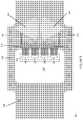
- FIG. 8illustrates a physical layout of the semiconductor package of FIG. 7 with the high-pass output matching network integrated in a multilayer circuit board from a plan-view perspective, according to an embodiment.
- FIG. 9illustrates a physical layout of the semiconductor package of FIG. 7 with the high-pass output matching network integrated in a multilayer circuit board from an isometric view perspective, according to an embodiment.
- FIG. 10illustrates a circuit topology for a semiconductor package with a high-pass output matching network and low-frequency termination capacitor, according to an embodiment.
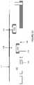
- FIG. 11illustrates a physical layout of the semiconductor package of FIG. 10 , with the high-pass output matching network integrated in a multilayer circuit board and a low-frequency termination capacitor mounted to an upper side of the multilayer circuit board, from a plan-view perspective, according to an embodiment.
- FIG. 12illustrates a physical layout of the semiconductor package of FIG. 10 , with the high-pass output matching network integrated in a multilayer circuit board and a low-frequency termination capacitor mounted to an upper side of the multilayer circuit board, from an isometric view perspective, according to an embodiment.
- FIG. 13illustrates a side-view of a multilayer circuit board with a thin surface-mount capacitor embedded within the multilayer circuit board, according to an embodiment.
- the package designis treated as part of the electrical design of the system instead of a just a mechanical component.
- the packageincludes a multilayer printed circuit board.
- the multi-layer circuit boardcan include a minimum of four layers, two of which are ground layers and two of which are signal layers. The signal and ground layers can be interleaved with one another to reduce interference and improve performance.
- Various RF componentscan be embedded within the multi-layer circuit board using the embedded signal layer. Examples of these RF components include integrated harmonics resonators, balanced power combiner networks, etc. In this way, fewer external components are needed and space efficiency of the package is improved.
- Embodiments of a multilayer circuit board described hereininclude an embedded dielectric layer that is disposed between embedded signal and ground layers. This design allows for the formation of embedded RF components with advantageous electrical characteristics.
- the embedded dielectric layerhas a substantially higher dielectric constant than typical PCB materials that are used to separate and insulate the various layers.
- the embedded dielectric layermay be formed from a polymer laminate material with a dielectric constant of between 4 and 30 and a thickness from 2 ⁇ m to 24 ⁇ m.
- typical PCB dielectric layershave a dielectric constant of 3.7 and a typical minimum thickness of 100 ⁇ m.
- an embedded capacitor with a capacitance value of at least 100 pF (picofarads)is formed in the multilayer circuit board.
- a capacitor of this magnitudeis not achievable using conventionally known PCB materials (e.g., composite fiber) as the interlayer dielectric while maintaining typical package size constraints, e.g., 10 mm ⁇ 7 mm.
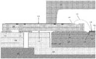
- FIG. 1illustrates a partial sectional view of a semiconductor package, according to an embodiment.
- the semiconductor packageincludes a metal baseplate 100 having a die attach region 102 and a peripheral region 104 , a transistor die 106 attached to the die attach region 102 of the baseplate 100 , a multilayer circuit board 108 such as a PCB for providing electrical connections to the transistor die 106 , and an optional lid 110 for enclosing the transistor die 106 .
- the baseplate 100is made of an electrically and thermally conductive material such as Cu, CPC (copper, copper-molybdenum, copper laminate structure), CuW, etc.
- the transistor die 106 attached to the baseplate 100is a power transistor die such as an RF amplifier die.
- the transistor die 106can be an LDMOS (laterally diffused metal oxide semiconductor), vertical power MOSFET (metal oxide semiconductor field effect transistor) or GaN RF power transistor die.
- the transistor die 106has a reference terminal 112 such as a source or emitter terminal attached to the die attach region 102 and an RF terminal 114 such as a drain or collector terminal facing away from the baseplate 100 .
- the control (gate) terminal of the transistor dieis out of view in FIG. 1 .
- More than one transistor diecan be attached to the baseplate 100 , e.g., in the case of a Doherty amplifier in which a main and one or more peaking amplifiers can be attached to the baseplate 100
- the multilayer circuit board 108has a first side 116 attached to the peripheral region 104 of the baseplate 100 and a second side 118 facing away from the baseplate 100 .
- the multilayer circuit board 108extends beyond an exterior sidewall 120 of the baseplate 100 for attachment to another circuit board 122 .
- the semiconductor packageis connected to a global printed circuit board 122 .
- the global printed circuit board 122is part of a sub-system or system that incorporates the semiconductor package as a constituent component. Other semiconductor devices that are part of this sub-system or system can be connected to the global printed circuit board 122 as well.
- This global printed circuit board 122can have a recessed region for receiving the baseplate 100 of the semiconductor package.
- a metal slug 124can be disposed in the recess for enhancing the thermal and electrical conduction between the global printed circuit board 122 and the multilayer circuit board 108 .
- the global printed circuit board 122may include a heatsink 126 containing aluminum or copper, for example, which attaches to the baseplate 100 of the semiconductor package.
- the RF terminal 114 of the transistor die 106is electrically connected to the multilayer circuit board 108 , which in turn is connected to the global printed circuit board 122 .
- an electrically conductive bond wire 128forms a direct electrical connection between the RF terminal 114 of the transistor die 106 and a first bond pad 130 that is disposed on the second side 118 of the multilayer circuit board 108 .
- the multilayer circuit board 108further includes two pads 132 , 134 disposed on the first side of the 116 . The first pad 132 directly faces and electrically connects to a signal pad of the global printed circuit board 122 , and thus forms a signal connection between the two.
- the second pad 134directly faces and electrically connects to a ground pad of the global printed circuit board 122 (as well as the baseplate 100 ), and thus forms a ground connection between the two.
- the multilayer circuit board 108contains conductive signal layers and via structures that connect the first bond pad 130 and the second bond pad 132 . Using these conductive layers, the multilayer circuit board 108 connects the RF terminal 114 of the transistor die 106 to the global printed circuit board 122 .
- an RF impedance matching networkcan be embedded in the multilayer circuit board 108 and coupled to the RF terminal 114 of the transistor die 106 so as to match the impedance of the packaged device to a desired value (e.g., 50 ohms).
- the multilayer circuit board 108includes a number of conductive layers. According to an embodiment, the multilayer circuit board 108 has four electrically conductive layers: a first signal layer 136 ; a first ground layer 138 ; a second signal layer 140 ; and a second ground layer 142 . Each of these layers is formed from a standard conductive material, such as copper.
- the first signal layer 136is disposed at the second side 118 of the multilayer circuit board 108 and the second ground layer 142 is disposed at the first side 116 of the multilayer circuit board 108 .
- first signal layer 136 and the second ground layer 142are disposed at outer, opposing sides of the multilayer circuit board 108 .
- “disposed at the first side” or “disposed at the second side,” as the case may be,refers to the fact that outer side of the particular element is coextensive with the first or second side of the multilayer circuit board.
- the first ground layer 138 and the second signal layer 140are embedded in the multilayer circuit board.
- embeddedrefers to the fact that the particular element is incorporated into the structure of the multilayer circuit board 108 and is separated from both the first side 116 and the second side 118 by another element or layer.
- the multilayer circuit board 108includes a first embedded layer 144 disposed between the first signal layer 136 and the first ground layer 138 .
- the first embedded layer 144 and the first signal layer 136separate the first ground layer 138 from the second surface 118 .
- the multilayer circuit board 108includes a second embedded layer 146 disposed between the second signal layer 140 and the second ground layer 142 .
- the second embedded layer 146 and the second ground layer 142separate the second signal layer 140 from the first surface 116 .
- the first embedded layer 144 and the second embedded layer 146are formed from an insulative pre-impregnated composite fiber material, such as polytetrafluoroethylene, FR-1, FR-2, FR-3, FR-4, FR-5, FR-6, G-10, CEM-1, CEM-2, CEM-3, CEM-4, CEM-5, etc.
- the first and second embedded layers 144 , 146have a thickness of at least 75 ⁇ m and according to one embodiment, have a thickness of about 100 ⁇ m.
- the multilayer circuit board 108further includes an embedded dielectric layer 148 disposed between the first ground layer 138 and the second signal layer 140 .
- the first ground layer 138 and the second signal layer 140are thus arranged in a parallel plate-capacitor configuration.
- the embedded dielectric layer 148directly contacts the first ground layer 138 and the second signal layer 140 .
- Equation 1The capacitance (C) of a parallel plate-capacitor is given by equation 1 as follows:
- the embedded dielectric layer 148is formed from a polymer capacitance laminate material with a high dielectric constant, e.g., between 4 and 30, and more particularly above 10 in some embodiments.
- the embedded dielectric layer 148may have a thickness of between 2 ⁇ m and 50 ⁇ m, and more particularly between 2 ⁇ m and 24 ⁇ m is some embodiments.
- the multilayer circuit board 108also includes via structures for connecting and/or providing electrical access to various components. More particularly, FIG. 2A depicts an insulated signal via 150 for connecting sections of the first and second signal layers 136 , 140 together.
- the insulated signal via 150extends through the first embedded layer 144 . Similar structures can be used to connect any two layers together.
- the insulated signal via 150may include a cap 152 such as a copper cap in the case of a copper via and a top pad 154 adjacent the cap 152 in the first (uppermost) signal layer 136 .
- the bottom of the insulated signal via 150includes a conductive pad 156 that contacts a portion of the second signal layer 140 .
- FIG. 2Billustrates a sectional view of an insulated path via 158 that extends from the first side 116 to the second side 118 and extends through all of the layers disposed between.
- the insulated path via 158electrically contacts the second ground layer 142 by a conductive pad 156 and the first ground layer 140 by another conductive pad 156 .
- the insulated path via 158extends to the second side 118 in a region of the multilayer circuit board 108 that is a devoid of the first signal layer 136 .
- the first and second ground layers 140 , 142are connected together and are electrically accessible at the second side 118 of the multilayer circuit board 108 by one of the conductive pads 156 .
- a ground terminal of the multilayer circuit board 108can be formed by the caps 220 on both sides of the multilayer circuit board 108 .
- the circuitincludes the transistor die 106 previously discussed with reference to FIG. 1 .
- the drain terminal of the transistor die 106is electrically connected to the multilayer circuit board 108 by the electrically conductive bond wire 128 previously discussed with reference to FIG. 1 .
- the bond wire 128connects to a first bond pad 154 of the multilayer circuit board 108 , which may be formed in the first signal layer 136 and is represented by a first transmission line TL 1 in the circuit schematic.
- the bond wire 128is connected, via the first bond pad 154 , to a shunt LC network 160 that is provided by the multilayer circuit board 108 .
- the shunt LC network 160includes reactive components that are configured to transform the output impedance of the circuit to a desired matching value (e.g., 50 ohms).
- the shunt LC network 160includes a second transmission line TL 2 , which schematically represents one of the insulated signal vias 150 previously described.
- the second transmission line TL 2electrically connects the first transmission line TL 1 (i.e., the top level bond pad) to an embedded reactive component that is integrated in multilayer circuit board 108 .
- this embedded reactive componentis an embedded capacitor C 1 .
- the positive electrode of the embedded capacitor C 1is formed by a first isolated section of the second signal layer 140
- the ground electrode of the first capacitoris formed by a first isolated section of the first ground layer 138 .
- the embedded dielectric layer 148is disposed between the two electrodes, i.e., so as to form a parallel plate capacitor described with reference to FIG. 2
- the first transmission line TL 1 and the second transmission line TL 2are connected to a third transmission line TL 3 , which may be provided by another isolated section of the first signal layer 136 .
- the third transmission line TL 3connects to a package terminal, which in turn may be connected to the global circuit board 122 described with reference to FIG. 1 .
- FIG. 4an exemplary circuit topology is depicted, according to another embodiment.
- the circuit topology of FIG. 4may be substantially similar or identical to that of FIG. 3 with the exception that the shunt LC network 160 is configured with a shunt inductor 162 and a radial stub 164 .
- one of the insulated signal vias 150connects the first transmission line TL 1 (i.e., the top level bond pad) to a shunt inductor 162 .
- the shunt inductor 162may be provided by a linear strip of the second signal layer 140 .
- the shunt inductor 162connects to an open-circuit radial stub 164 .
- a physical layout of the semiconductor package of FIG. 4is depicted.
- similarly numbered elementsrefer to corresponding circuit elements schematically represented in FIG. 4 .
- a plurality of the bond wires 128extend directly between the transistor die 106 and a plurality of bond pads 154 that are formed in the first signal layer 136 .
- These bond pads 154are electrically connected to the second signal layer 140 by insulated signal vias 150 .
- the shunt inductor 162 and the open-circuit radial stub 164are formed in the second signal layer 140 and connect to the bond pads 154 (and to the bond wires 128 ) by the insulated signal vias 150 .
- the multilayer circuit board 108may include a plurality of insulated path vias 158 as described with reference to FIG. 2B of the present Specification. These insulated path vias 158 are electrically connected to the ground layers to provide improved electrical isolation.
- radial stubsare used as open-circuit 1 ⁇ 4 wave terminations in RF circuits and have enhanced broadband frequency response.
- a radial stubcan be formed on the top layer as a microstripline component (i.e., a thin flat conductor which is parallel to a ground plane).
- the relatively low equivalent dielectric constant in this kind of PCB 2 layer substratemeans that compact radial stubs are not possible for certain frequency bands. That is, in conventional PCB 2 layer substrates, package area can become the gating factor for the radial stub.
- the presently configured multilayer circuit board 108allows for the radial stub 164 to be configured as a stripline component (i.e., a flat strip of metal which is sandwiched between two parallel ground planes) with a relatively compact design.
- the embedded capacitance materialsubstantially increases the capacitance per unit area of the stripline components and this leads a very compact radial stub layout.
- a layout of 2 mm 2 for the embedded componentprovides a capacitance of 100 pF, and this layout can be easily integrated inside a typical package outline of 10 mm ⁇ 7 mm (i.e., 70 mm 2 ).
- the radial stub layout area needed to achieve 100 pFis 200 mm 2 , and this size component cannot be integrated within a 10 mm ⁇ 7 mm package outline.
- FIG. 7an exemplary circuit topology is depicted, according to another embodiment.
- the circuit of FIG. 7differs from the circuit of FIG. 4 with respect to the configuration of the bond wires 128 .
- the bond wires 128are configured with two separate branches.
- a first branch 166 of the bond wires 128is directly connected between the RF terminal of the transistor die 106 and a first bond pad 168 , which may be provided by a first isolated portion of the first signal layer 136 in the manner previously discussed.
- the first bond pad 168is connected to an output node of the multilayer circuit board 108 by a length of microstripline 174 .
- a second branch 170 of the bond wires 128is directly connected between the RF terminal of the transistor die 106 and a second bond pad 172 , which may be provided by a second isolated portion of the first signal layer 136 that is electrically disconnected from the first bond pad 168 .
- An insulated signal via 150connects the second bond pad 172 to the radial stub 164 .
- a set of the first bond pads 168may be arranged in a similar manner as the bond pads 154 shown in FIGS. 5 and 6 .
- Another set of the second bond pads 172may be disposed on either side of the first bond pads 168 . That is, the first bond pads 168 may be disposed between the second bond pads 172 .
- a plurality of insulated path vias 158 that are electrically groundedmay be disposed between the first bond pads 168 and the second bond pads 172 to provide increased electrical shielding between the two.
- the first branch 166 of the bond wires 128extends in a first direction D 1 between the transistor die 106 and the first bond pads 168 .
- the first direction D 1extends left to right, and represents a direction of the shortest path between the RF terminal 114 of the transistor die 106 and the first bond pads 168 .
- the second branch 170 of the bond wires 128extends in a second direction that is non-parallel to the first direction. That is, the second direction is disposed at an angle relative first direction. In the embodiment of FIG. 8 , the second branch 170 of the bond wires 128 form an acute angle with the first branch 166 of the bond wires 128 .
- This arrangementincreases the separation distance between the first and second branches 176 , 170 and consequently reduces the mutual inductance between the various bonding wires. As a result, parasitic effects are mitigated. Different orientations may be achieved, depending on the positioning of the bond pads 154 .
- FIG. 10an exemplary circuit topology is depicted, according to another embodiment.
- the circuit of FIG. 10has a substantially similar topology to the circuit of FIG. 4 , with the exception that an additional capacitor 178 is incorporated into the output matching network to improve the linearity of the system by providing a low frequency termination.
- a low frequency termination capacitorcan be provided outside of the package using a discrete component.
- this arrangementsuffers from the drawback that the parasitic inductance and capacitance of the external electrical connections (e.g., bond wires) to the additional capacitor degrade the bandwidth of the low frequency termination by as much as 100 MHz to 200 MHz.
- the capacitoris disposed as close to the transistor as possible to mitigate these parasitic effects.
- the multilayer circuit board 108 design described hereinallows for the additional capacitor 178 to be implemented as a discrete capacitor formed on or in the multilayer circuit board 108 very close to the transistor die 106 . That is, the low frequency capacitor can incorporated into the device package. As a result, the bandwidth of the low frequency termination is improved.
- the additional capacitor 178is implemented as a surface-mount capacitor, i.e., a discrete capacitor with lower facing terminals that directly contact a bond pad, and is bonded to the second side 118 of the multilayer circuit board 108 .
- the multilayer circuit boardincludes 108 a third bond pad 180 which is formed by a third isolated portion of the first signal layer 136 .
- the third bond pad 180is electrically disconnected from the other bond pads 154 .
- a positive electrode of the low frequency termination capacitor 178is electrically connected to at least one of the embedded reactive components (i.e., the shunt inductor 162 and the radial stub 164 in the embodiment of FIGS. 11-12 ) by an insulated signal via 150 .
- the negative electrode of the low frequency termination capacitor 178is connected to electrical ground by one of the path vias 158 .
- the multilayer circuit board 108 described hereinprovides the circuit topology of FIG. 10 in a space efficient manner by providing the radial stub 164 embedded within the multilayer circuit board 108 while using overlapping surface area on the top surface of the multilayer circuit board 108 for the low frequency termination capacitor 178 .
- the low frequency termination capacitor 178is combined with the circuit and corresponding layouts described with reference to FIGS. 4-6 . However, this is just one example. Alternatively, the low frequency termination capacitor 178 could be combined with different configurations, such as the circuit and corresponding layouts described with reference to FIGS. 7-9 .
- the multilayer circuit board 108may be configured similarly as the multilayer circuit board described with reference to FIGS. 11 and 12 , with the exception that the low frequency termination capacitor 178 is disposed inside of the multilayer circuit board 108 instead of on the upper surface.
- the low frequency termination capacitor 178is an ultra-thin surface mount device. These devices can be embedded into the multilayer circuit board 108 during the fabrication process. More particularly, an ultra-thin surface mount device can be embedded in one or both of the embedded layers 144 , 146 , during the lamination process that forms these layers. Isolated sections of the signal and/or ground layers can be formed to provide bonding locations for the ultra-thin surface mount device.
- the insulated signal vias 150 and path vias 158 described hereincan be used to connect these bonding locations with external bond pads.
Landscapes
- Engineering & Computer Science (AREA)
- Microelectronics & Electronic Packaging (AREA)
- Physics & Mathematics (AREA)
- Computer Hardware Design (AREA)
- Power Engineering (AREA)
- Condensed Matter Physics & Semiconductors (AREA)
- General Physics & Mathematics (AREA)
- Geometry (AREA)
- Production Of Multi-Layered Print Wiring Board (AREA)
- Microwave Amplifiers (AREA)
Abstract
Description
where ε0=vacuum permittivity, εr=relative permittivity of the dielectric, A=plate area, and t=thickness of the dielectric.
Claims (20)
Priority Applications (2)
| Application Number | Priority Date | Filing Date | Title |
|---|---|---|---|
| US16/209,018US10575394B2 (en) | 2016-02-18 | 2018-12-04 | PCB based semiconductor package with impedance matching network elements integrated therein |
| US16/731,370US10743404B2 (en) | 2016-02-18 | 2019-12-31 | PCB based semiconductor device |
Applications Claiming Priority (2)
| Application Number | Priority Date | Filing Date | Title |
|---|---|---|---|
| US15/046,923US10225922B2 (en) | 2016-02-18 | 2016-02-18 | PCB based semiconductor package with impedance matching network elements integrated therein |
| US16/209,018US10575394B2 (en) | 2016-02-18 | 2018-12-04 | PCB based semiconductor package with impedance matching network elements integrated therein |
Related Parent Applications (1)
| Application Number | Title | Priority Date | Filing Date |
|---|---|---|---|
| US15/046,923ContinuationUS10225922B2 (en) | 2016-02-18 | 2016-02-18 | PCB based semiconductor package with impedance matching network elements integrated therein |
Related Child Applications (1)
| Application Number | Title | Priority Date | Filing Date |
|---|---|---|---|
| US16/731,370ContinuationUS10743404B2 (en) | 2016-02-18 | 2019-12-31 | PCB based semiconductor device |
Publications (2)
| Publication Number | Publication Date |
|---|---|
| US20190110358A1 US20190110358A1 (en) | 2019-04-11 |
| US10575394B2true US10575394B2 (en) | 2020-02-25 |
Family
ID=58044093
Family Applications (3)
| Application Number | Title | Priority Date | Filing Date |
|---|---|---|---|
| US15/046,923Active2036-10-27US10225922B2 (en) | 2016-02-18 | 2016-02-18 | PCB based semiconductor package with impedance matching network elements integrated therein |
| US16/209,018ActiveUS10575394B2 (en) | 2016-02-18 | 2018-12-04 | PCB based semiconductor package with impedance matching network elements integrated therein |
| US16/731,370ActiveUS10743404B2 (en) | 2016-02-18 | 2019-12-31 | PCB based semiconductor device |
Family Applications Before (1)
| Application Number | Title | Priority Date | Filing Date |
|---|---|---|---|
| US15/046,923Active2036-10-27US10225922B2 (en) | 2016-02-18 | 2016-02-18 | PCB based semiconductor package with impedance matching network elements integrated therein |
Family Applications After (1)
| Application Number | Title | Priority Date | Filing Date |
|---|---|---|---|
| US16/731,370ActiveUS10743404B2 (en) | 2016-02-18 | 2019-12-31 | PCB based semiconductor device |
Country Status (5)
| Country | Link |
|---|---|
| US (3) | US10225922B2 (en) |
| EP (2) | EP3640982B1 (en) |
| KR (1) | KR102093572B1 (en) |
| CN (1) | CN108701683B (en) |
| WO (1) | WO2017140737A1 (en) |
Families Citing this family (12)
| Publication number | Priority date | Publication date | Assignee | Title |
|---|---|---|---|---|
| US20170325327A1 (en)* | 2016-04-07 | 2017-11-09 | Massachusetts Institute Of Technology | Printed circuit board for high power components |
| US10141303B1 (en) | 2017-09-20 | 2018-11-27 | Cree, Inc. | RF amplifier package with biasing strip |
| US12283555B2 (en) | 2018-03-23 | 2025-04-22 | Analog Devices International Unlimited Company | Semiconductor packages |
| JP2020205519A (en)* | 2019-06-17 | 2020-12-24 | 株式会社村田製作所 | Circuit board, inductor and radio equipment |
| US11503704B2 (en)* | 2019-12-30 | 2022-11-15 | General Electric Company | Systems and methods for hybrid glass and organic packaging for radio frequency electronics |
| US12166003B2 (en)* | 2020-04-03 | 2024-12-10 | Macom Technology Solutions Holdings, Inc. | RF amplifier devices including top side contacts and methods of manufacturing |
| US11837457B2 (en) | 2020-09-11 | 2023-12-05 | Wolfspeed, Inc. | Packaging for RF transistor amplifiers |
| US11356070B2 (en) | 2020-06-01 | 2022-06-07 | Wolfspeed, Inc. | RF amplifiers having shielded transmission line structures |
| US11670605B2 (en) | 2020-04-03 | 2023-06-06 | Wolfspeed, Inc. | RF amplifier devices including interconnect structures and methods of manufacturing |
| US12100630B2 (en) | 2020-11-13 | 2024-09-24 | Macom Technology Solutions Holdings, Inc. | Packaged RF power device with PCB routing outside protective member |
| US20230344393A1 (en)* | 2022-04-08 | 2023-10-26 | Skyworks Solutions, Inc. | Power amplifier systems with frequency response compensation |
| CN117812804A (en)* | 2022-09-26 | 2024-04-02 | 鹏鼎控股(深圳)股份有限公司 | Circuit board and manufacturing method thereof |
Citations (39)
| Publication number | Priority date | Publication date | Assignee | Title |
|---|---|---|---|---|
| US3986196A (en) | 1975-06-30 | 1976-10-12 | Varian Associates | Through-substrate source contact for microwave FET |
| US5067004A (en)* | 1989-12-13 | 1991-11-19 | Digital Equipment Corporation | Module for interconnecting integrated circuits |
| EP0563873A2 (en) | 1992-04-03 | 1993-10-06 | Matsushita Electric Industrial Co., Ltd. | High frequency ceramic multi-layer substrate |
| US5438478A (en) | 1992-10-20 | 1995-08-01 | Ibiden Co., Ltd. | Electronic component carriers and method of producing the same as well as electronic devices |
| US5728248A (en) | 1995-03-13 | 1998-03-17 | Hestia Technologies, Inc. | Method for making a multi-tier laminate substrate with internal heat spreader |
| US5776512A (en) | 1995-05-26 | 1998-07-07 | Hestia Technologies, Inc. | Apparatus for encapsulating electronic packages |
| US5798014A (en) | 1995-02-02 | 1998-08-25 | Hestia Technologies, Inc. | Methods of making multi-tier laminate substrates for electronic device packaging |
| JPH10242377A (en) | 1997-02-25 | 1998-09-11 | Hitachi Ltd | High frequency power amplifier module |
| US5843808A (en) | 1996-01-11 | 1998-12-01 | Asat, Limited | Structure and method for automated assembly of a tab grid array package |
| US5973389A (en) | 1997-04-22 | 1999-10-26 | International Business Machines Corporation | Semiconductor chip carrier assembly |
| US6172305B1 (en)* | 1997-07-31 | 2001-01-09 | Kyocera Corporation | Multilayer circuit board |
| US6261868B1 (en) | 1999-04-02 | 2001-07-17 | Motorola, Inc. | Semiconductor component and method for manufacturing the semiconductor component |
| US6329713B1 (en) | 1998-10-21 | 2001-12-11 | International Business Machines Corporation | Integrated circuit chip carrier assembly comprising a stiffener attached to a dielectric substrate |
| US6365828B1 (en)* | 1999-10-22 | 2002-04-02 | Nec Corporation | Electromagnetic interference suppressing device and circuit |
| US20020089798A1 (en)* | 1998-12-04 | 2002-07-11 | Nec Corporation | Interlayer structure with multiple insulative layers with different frequency characteristics |
| US6511866B1 (en) | 2001-07-12 | 2003-01-28 | Rjr Polymers, Inc. | Use of diverse materials in air-cavity packaging of electronic devices |
| US20030063427A1 (en)* | 2001-08-27 | 2003-04-03 | Nec Corporation | Variable capacitor and a variable inductor |
| US20030063453A1 (en)* | 2001-09-28 | 2003-04-03 | Fujitsu Limited | Multilayer wiring circuit board |
| WO2003037048A1 (en) | 2001-10-22 | 2003-05-01 | Micro Mobio Corporation | Multilayer rf amplifier module |
| JP2003179181A (en) | 2001-12-11 | 2003-06-27 | Ngk Spark Plug Co Ltd | Resin wiring board |
| US20030151128A1 (en) | 2002-02-14 | 2003-08-14 | Mitsubishi Denki Kabushiki Kaisha | Semiconductor device |
| DE10223035A1 (en) | 2002-05-22 | 2003-12-04 | Infineon Technologies Ag | Electronic component with cavity housing, in particular high-frequency power module |
| US20040012938A1 (en) | 2001-08-24 | 2004-01-22 | Sylvester Mark F. | Interconnect module with reduced power distribution impedance |
| US6691296B1 (en)* | 1998-02-02 | 2004-02-10 | Matsushita Electric Industrial Co., Ltd. | Circuit board design aiding |
| US7298046B2 (en) | 2003-01-10 | 2007-11-20 | Kyocera America, Inc. | Semiconductor package having non-ceramic based window frame |
| CN101308727A (en) | 2007-04-13 | 2008-11-19 | 阿维科斯公司 | Land grid feedthrough low esl technology |
| CN101553918A (en) | 2005-10-24 | 2009-10-07 | 飞思卡尔半导体公司 | Semiconductor structure and assembly method |
| CN101625730A (en) | 2008-07-07 | 2010-01-13 | 国际商业机器公司 | Radio frequency integrated circuit packages |
| DE102010038246A1 (en) | 2009-10-16 | 2011-08-25 | Infineon Technologies AG, 85579 | Surface mount wireless open cavity package for high power RF applications |
| US8013429B2 (en) | 2009-07-14 | 2011-09-06 | Infineon Technologies Ag | Air cavity package with copper heat sink and ceramic window frame |
| EP2575167A2 (en) | 2011-09-30 | 2013-04-03 | Fujitsu Limited | Electronic device |
| US20130148314A1 (en)* | 2011-06-29 | 2013-06-13 | Ngk Insulators,Ltd. | Circuit board for peripheral circuits of high-capacity modules, and a high-capacity module including a peripheral circuit using the circuit board |
| US20130256858A1 (en)* | 2012-03-28 | 2013-10-03 | Infineon Technologies North America Corp. | PCB Based RF-Power Package Window Frame |
| US20130299219A1 (en)* | 2011-02-15 | 2013-11-14 | Murata Manufacturing Co., Ltd. | Multilayer circuit board and method for manufacturing the same |
| US20140028518A1 (en)* | 2012-07-26 | 2014-01-30 | Shawn Xavier Arnold | Antenna Structures and Shield Layers on Packaged Wireless Circuits |
| US20140078702A1 (en)* | 2012-09-18 | 2014-03-20 | Sony Corporation | Multilayer printed circuit board |
| US20140117495A1 (en)* | 2012-10-31 | 2014-05-01 | Delta Electronics (Shanghai) Co., Ltd. | Switch circuit package module |
| CN103887264A (en) | 2012-12-21 | 2014-06-25 | 三星电机株式会社 | Pre space transformer, space transformer, and semiconductor device inspecting apparatus |
| US20170034913A1 (en)* | 2015-07-28 | 2017-02-02 | Infineon Technologies Ag | PCB Based Semiconductor Package Having Integrated Electrical Functionality |
Family Cites Families (6)
| Publication number | Priority date | Publication date | Assignee | Title |
|---|---|---|---|---|
| JPH07123177B2 (en)* | 1986-08-29 | 1995-12-25 | 日立化成工業株式会社 | High frequency circuit board manufacturing method |
| EP1265466A3 (en)* | 2001-06-05 | 2004-07-21 | Dai Nippon Printing Co., Ltd. | Method for fabrication wiring board provided with passive element and wiring board provided with passive element |
| CN102481598B (en)* | 2009-06-11 | 2014-07-09 | 罗杰斯公司 | Dielectric material, method of forming subassembly therefrom, and subassembly formed thereby |
| KR20130113032A (en)* | 2012-04-05 | 2013-10-15 | 에스케이하이닉스 주식회사 | Semiconductor substrate, semiconductor chip having the same and stacked semiconductor package |
| KR20140008871A (en)* | 2012-07-12 | 2014-01-22 | 삼성전기주식회사 | Epoxy resin composition for build-up insulating film, insulating film made therefrom, and multilayer printed circuit boards having the same |
| CN104066265A (en)* | 2013-03-22 | 2014-09-24 | 叶云照 | multilayer printed circuit board structure |
- 2016
- 2016-02-18USUS15/046,923patent/US10225922B2/enactiveActive
- 2017
- 2017-02-15KRKR1020187025730Apatent/KR102093572B1/enactiveActive
- 2017-02-15EPEP19207270.0Apatent/EP3640982B1/enactiveActive
- 2017-02-15CNCN201780012179.4Apatent/CN108701683B/enactiveActive
- 2017-02-15WOPCT/EP2017/053424patent/WO2017140737A1/ennot_activeCeased
- 2017-02-15EPEP17705143.0Apatent/EP3398206B1/enactiveActive
- 2018
- 2018-12-04USUS16/209,018patent/US10575394B2/enactiveActive
- 2019
- 2019-12-31USUS16/731,370patent/US10743404B2/enactiveActive
Patent Citations (46)
| Publication number | Priority date | Publication date | Assignee | Title |
|---|---|---|---|---|
| US3986196A (en) | 1975-06-30 | 1976-10-12 | Varian Associates | Through-substrate source contact for microwave FET |
| US5067004A (en)* | 1989-12-13 | 1991-11-19 | Digital Equipment Corporation | Module for interconnecting integrated circuits |
| EP0563873A2 (en) | 1992-04-03 | 1993-10-06 | Matsushita Electric Industrial Co., Ltd. | High frequency ceramic multi-layer substrate |
| US5438478A (en) | 1992-10-20 | 1995-08-01 | Ibiden Co., Ltd. | Electronic component carriers and method of producing the same as well as electronic devices |
| US5798014A (en) | 1995-02-02 | 1998-08-25 | Hestia Technologies, Inc. | Methods of making multi-tier laminate substrates for electronic device packaging |
| US5728248A (en) | 1995-03-13 | 1998-03-17 | Hestia Technologies, Inc. | Method for making a multi-tier laminate substrate with internal heat spreader |
| US5776512A (en) | 1995-05-26 | 1998-07-07 | Hestia Technologies, Inc. | Apparatus for encapsulating electronic packages |
| US5843808A (en) | 1996-01-11 | 1998-12-01 | Asat, Limited | Structure and method for automated assembly of a tab grid array package |
| JPH10242377A (en) | 1997-02-25 | 1998-09-11 | Hitachi Ltd | High frequency power amplifier module |
| US5973389A (en) | 1997-04-22 | 1999-10-26 | International Business Machines Corporation | Semiconductor chip carrier assembly |
| US6172305B1 (en)* | 1997-07-31 | 2001-01-09 | Kyocera Corporation | Multilayer circuit board |
| US6691296B1 (en)* | 1998-02-02 | 2004-02-10 | Matsushita Electric Industrial Co., Ltd. | Circuit board design aiding |
| US6329713B1 (en) | 1998-10-21 | 2001-12-11 | International Business Machines Corporation | Integrated circuit chip carrier assembly comprising a stiffener attached to a dielectric substrate |
| US6503821B2 (en) | 1998-10-21 | 2003-01-07 | International Business Machines Corporation | Integrated circuit chip carrier assembly |
| US20020089798A1 (en)* | 1998-12-04 | 2002-07-11 | Nec Corporation | Interlayer structure with multiple insulative layers with different frequency characteristics |
| US6261868B1 (en) | 1999-04-02 | 2001-07-17 | Motorola, Inc. | Semiconductor component and method for manufacturing the semiconductor component |
| US6365828B1 (en)* | 1999-10-22 | 2002-04-02 | Nec Corporation | Electromagnetic interference suppressing device and circuit |
| US6511866B1 (en) | 2001-07-12 | 2003-01-28 | Rjr Polymers, Inc. | Use of diverse materials in air-cavity packaging of electronic devices |
| CN1526162A (en) | 2001-07-12 | 2004-09-01 | RJR�ۺ���ɷ�����˾ | Use of diverse materials in air-cavity packaging of electronic devices |
| US20040012938A1 (en) | 2001-08-24 | 2004-01-22 | Sylvester Mark F. | Interconnect module with reduced power distribution impedance |
| US20030063427A1 (en)* | 2001-08-27 | 2003-04-03 | Nec Corporation | Variable capacitor and a variable inductor |
| US20030063453A1 (en)* | 2001-09-28 | 2003-04-03 | Fujitsu Limited | Multilayer wiring circuit board |
| WO2003037048A1 (en) | 2001-10-22 | 2003-05-01 | Micro Mobio Corporation | Multilayer rf amplifier module |
| JP2003179181A (en) | 2001-12-11 | 2003-06-27 | Ngk Spark Plug Co Ltd | Resin wiring board |
| US20030151128A1 (en) | 2002-02-14 | 2003-08-14 | Mitsubishi Denki Kabushiki Kaisha | Semiconductor device |
| DE10223035A1 (en) | 2002-05-22 | 2003-12-04 | Infineon Technologies Ag | Electronic component with cavity housing, in particular high-frequency power module |
| CN101080800A (en) | 2003-01-10 | 2007-11-28 | 基奥塞拉美国股份有限公司 | Semiconductor package having non-ceramic based window frame |
| US7582964B2 (en) | 2003-01-10 | 2009-09-01 | Kyocera America, Inc. | Semiconductor package having non-ceramic based window frame |
| US7298046B2 (en) | 2003-01-10 | 2007-11-20 | Kyocera America, Inc. | Semiconductor package having non-ceramic based window frame |
| CN101553918A (en) | 2005-10-24 | 2009-10-07 | 飞思卡尔半导体公司 | Semiconductor structure and assembly method |
| CN101308727A (en) | 2007-04-13 | 2008-11-19 | 阿维科斯公司 | Land grid feedthrough low esl technology |
| CN101625730A (en) | 2008-07-07 | 2010-01-13 | 国际商业机器公司 | Radio frequency integrated circuit packages |
| US8013429B2 (en) | 2009-07-14 | 2011-09-06 | Infineon Technologies Ag | Air cavity package with copper heat sink and ceramic window frame |
| DE102010038246A1 (en) | 2009-10-16 | 2011-08-25 | Infineon Technologies AG, 85579 | Surface mount wireless open cavity package for high power RF applications |
| US20130299219A1 (en)* | 2011-02-15 | 2013-11-14 | Murata Manufacturing Co., Ltd. | Multilayer circuit board and method for manufacturing the same |
| US20130148314A1 (en)* | 2011-06-29 | 2013-06-13 | Ngk Insulators,Ltd. | Circuit board for peripheral circuits of high-capacity modules, and a high-capacity module including a peripheral circuit using the circuit board |
| EP2575167A2 (en) | 2011-09-30 | 2013-04-03 | Fujitsu Limited | Electronic device |
| US20130256858A1 (en)* | 2012-03-28 | 2013-10-03 | Infineon Technologies North America Corp. | PCB Based RF-Power Package Window Frame |
| US8907467B2 (en) | 2012-03-28 | 2014-12-09 | Infineon Technologies Ag | PCB based RF-power package window frame |
| US20150048492A1 (en) | 2012-03-28 | 2015-02-19 | Infineon Technologies Ag | PCB Based RF-Power Package Window Frame |
| US20140028518A1 (en)* | 2012-07-26 | 2014-01-30 | Shawn Xavier Arnold | Antenna Structures and Shield Layers on Packaged Wireless Circuits |
| US20140078702A1 (en)* | 2012-09-18 | 2014-03-20 | Sony Corporation | Multilayer printed circuit board |
| US20140117495A1 (en)* | 2012-10-31 | 2014-05-01 | Delta Electronics (Shanghai) Co., Ltd. | Switch circuit package module |
| CN103887264A (en) | 2012-12-21 | 2014-06-25 | 三星电机株式会社 | Pre space transformer, space transformer, and semiconductor device inspecting apparatus |
| US20170034913A1 (en)* | 2015-07-28 | 2017-02-02 | Infineon Technologies Ag | PCB Based Semiconductor Package Having Integrated Electrical Functionality |
| US9629246B2 (en) | 2015-07-28 | 2017-04-18 | Infineon Technologies Ag | PCB based semiconductor package having integrated electrical functionality |
Also Published As
| Publication number | Publication date |
|---|---|
| US20170245359A1 (en) | 2017-08-24 |
| US10743404B2 (en) | 2020-08-11 |
| EP3398206B1 (en) | 2019-12-11 |
| US10225922B2 (en) | 2019-03-05 |
| WO2017140737A1 (en) | 2017-08-24 |
| CN108701683A (en) | 2018-10-23 |
| US20200137877A1 (en) | 2020-04-30 |
| US20190110358A1 (en) | 2019-04-11 |
| KR20180114097A (en) | 2018-10-17 |
| EP3640982B1 (en) | 2021-01-13 |
| EP3398206A1 (en) | 2018-11-07 |
| CN108701683B (en) | 2021-08-13 |
| KR102093572B1 (en) | 2020-03-25 |
| EP3640982A1 (en) | 2020-04-22 |
Similar Documents
| Publication | Publication Date | Title |
|---|---|---|
| US10743404B2 (en) | PCB based semiconductor device | |
| CN109994436B (en) | PCB-based semiconductor package with integrated electrical functions | |
| EP3096353B1 (en) | Rf amplifier output circuit device with integrated current path | |
| JP6388428B2 (en) | Semiconductor device having impedance matching circuit and manufacturing method thereof | |
| US10381984B2 (en) | Amplifiers and amplifier modules with shunt inductance circuits that include high-Q capacitors | |
| US8901719B2 (en) | Transition from a chip to a waveguide port | |
| US9820401B2 (en) | Packaged RF power transistor device having next to each other a ground and a video lead for connecting a decoupling capacitor, RF power amplifier | |
| US9711466B2 (en) | Electronic apparatus operable in high frequencies | |
| JP6273247B2 (en) | High frequency semiconductor amplifier | |
| US9070685B2 (en) | Compound semiconductor integrated circuit | |
| JP7666175B2 (en) | Semiconductor device and package | |
| JP5661707B2 (en) | Compound semiconductor integrated circuit | |
| JP2010245819A (en) | Amplifier circuit | |
| US20250125286A1 (en) | Semiconductor device | |
| US20240292520A1 (en) | Matching circuit board and semiconductor device | |
| JPS6255721B2 (en) | ||
| JP4547823B2 (en) | High frequency module | |
| JP2005197926A (en) | Radio signal module and its manufacturing method | |
| JP2006203082A (en) | Integrated element | |
| WO2006072984A1 (en) | Semiconductor amplifier |
Legal Events
| Date | Code | Title | Description |
|---|---|---|---|
| AS | Assignment | Owner name:INFINEON TECHNOLOGIES AG, GERMANY Free format text:ASSIGNMENT OF ASSIGNORS INTEREST;ASSIGNOR:INFINEON TECHNOLOGIES AMERICAS CORP.;REEL/FRAME:047668/0189 Effective date:20160824 Owner name:CREE, INC., NORTH CAROLINA Free format text:ASSIGNMENT OF ASSIGNORS INTEREST;ASSIGNOR:INFINEON TECHNOLOGIES AG;REEL/FRAME:047668/0249 Effective date:20180306 Owner name:INFINEON TECHNOLOGIES AMERICAS CORP., CALIFORNIA Free format text:ASSIGNMENT OF ASSIGNORS INTEREST;ASSIGNORS:DANI, ASMITA;GOZZI, CRISTIAN;MU, QIANLI;REEL/FRAME:047668/0079 Effective date:20160219 | |
| FEPP | Fee payment procedure | Free format text:ENTITY STATUS SET TO UNDISCOUNTED (ORIGINAL EVENT CODE: BIG.); ENTITY STATUS OF PATENT OWNER: LARGE ENTITY | |
| STPP | Information on status: patent application and granting procedure in general | Free format text:DOCKETED NEW CASE - READY FOR EXAMINATION | |
| STPP | Information on status: patent application and granting procedure in general | Free format text:NON FINAL ACTION MAILED | |
| STPP | Information on status: patent application and granting procedure in general | Free format text:RESPONSE TO NON-FINAL OFFICE ACTION ENTERED AND FORWARDED TO EXAMINER | |
| STPP | Information on status: patent application and granting procedure in general | Free format text:NOTICE OF ALLOWANCE MAILED -- APPLICATION RECEIVED IN OFFICE OF PUBLICATIONS | |
| STPP | Information on status: patent application and granting procedure in general | Free format text:AWAITING TC RESP., ISSUE FEE NOT PAID | |
| STPP | Information on status: patent application and granting procedure in general | Free format text:PUBLICATIONS -- ISSUE FEE PAYMENT VERIFIED | |
| STPP | Information on status: patent application and granting procedure in general | Free format text:PUBLICATIONS -- ISSUE FEE PAYMENT VERIFIED | |
| STCF | Information on status: patent grant | Free format text:PATENTED CASE | |
| AS | Assignment | Owner name:WOLFSPEED, INC., NORTH CAROLINA Free format text:CHANGE OF NAME;ASSIGNOR:CREE, INC.;REEL/FRAME:058774/0432 Effective date:20211001 | |
| MAFP | Maintenance fee payment | Free format text:PAYMENT OF MAINTENANCE FEE, 4TH YEAR, LARGE ENTITY (ORIGINAL EVENT CODE: M1551); ENTITY STATUS OF PATENT OWNER: LARGE ENTITY Year of fee payment:4 | |
| AS | Assignment | Owner name:MACOM TECHNOLOGY SOLUTIONS HOLDINGS, INC., MASSACHUSETTS Free format text:ASSIGNMENT OF ASSIGNORS INTEREST;ASSIGNOR:WOLFSPEED, INC.;REEL/FRAME:066236/0086 Effective date:20231206 |