US10574894B2 - Systems and methods for stabilizing videos - Google Patents
Systems and methods for stabilizing videosDownload PDFInfo
- Publication number
- US10574894B2 US10574894B2US16/548,453US201916548453AUS10574894B2US 10574894 B2US10574894 B2US 10574894B2US 201916548453 AUS201916548453 AUS 201916548453AUS 10574894 B2US10574894 B2US 10574894B2
- Authority
- US
- United States
- Prior art keywords
- capture
- trajectory
- housing
- images
- view
- Prior art date
- Legal status (The legal status is an assumption and is not a legal conclusion. Google has not performed a legal analysis and makes no representation as to the accuracy of the status listed.)
- Active
Links
Images


Classifications
- H04N5/23258—
- H—ELECTRICITY
- H04—ELECTRIC COMMUNICATION TECHNIQUE
- H04N—PICTORIAL COMMUNICATION, e.g. TELEVISION
- H04N23/00—Cameras or camera modules comprising electronic image sensors; Control thereof
- H04N23/60—Control of cameras or camera modules
- H04N23/68—Control of cameras or camera modules for stable pick-up of the scene, e.g. compensating for camera body vibrations
- H04N23/681—Motion detection
- H04N23/6812—Motion detection based on additional sensors, e.g. acceleration sensors
- H—ELECTRICITY
- H04—ELECTRIC COMMUNICATION TECHNIQUE
- H04N—PICTORIAL COMMUNICATION, e.g. TELEVISION
- H04N23/00—Cameras or camera modules comprising electronic image sensors; Control thereof
- H04N23/60—Control of cameras or camera modules
- H04N23/68—Control of cameras or camera modules for stable pick-up of the scene, e.g. compensating for camera body vibrations
- H04N23/682—Vibration or motion blur correction
- H04N23/683—Vibration or motion blur correction performed by a processor, e.g. controlling the readout of an image memory
- H04N5/23267—
- H—ELECTRICITY
- H04—ELECTRIC COMMUNICATION TECHNIQUE
- H04N—PICTORIAL COMMUNICATION, e.g. TELEVISION
- H04N23/00—Cameras or camera modules comprising electronic image sensors; Control thereof
- H04N23/50—Constructional details
- H04N23/51—Housings
- H04N5/2252—
Definitions
- This disclosurerelates to stabilizing videos using positions of an image capture device during a capture duration.
- a videomay have been captured by an image capture device in motion.
- the motion of the image capture device during the capture of the videomay cause the video to appear jerky/shaky.
- Images with an optical field of viewmay be captured by an image capture device during a capture duration.
- Image information defining the images, position information characterizing positions of the image capture device at different moments within the capture duration, and/or other informationmay be obtained during the capture duration.
- An observed trajectory of the image capture device during the capture durationmay be determined based on the position information and/or other information.
- the observed trajectorymay reflect the positions of the image capture device at different moments within the capture duration.
- the observed trajectorymay include a first portion corresponding to a first moment within the capture duration and a second portion corresponding to a second moment subsequent to the first moment within the capture duration.
- a capture trajectory of the image capture devicemay be determined based on a subsequent portion of the observed trajectory and/or other information such that a portion of the capture trajectory corresponding to the first portion of the observed trajectory may be determined based on the second portion of the observed trajectory.
- the capture trajectorymay have smoother changes in the positions of the image capture device than the observed trajectory.
- Orientations of the capture field of view for the images with respect to the optical field of view of the imagesmay be determined based on the capture trajectory of the image capture device and/or other information.
- Video contentmay be generated based on visual content of the images within the capture field of view and/or other information.
- a system that stabilizes videosmay include one or more electronic storages, one or more processors, and/or other components.
- An electronic storagemay store image information, position information, information relating to an observed trajectory of an image capture device, information relating to a capture trajectory, information relating to an optical field of view, information relating to a capture field of view, information relating to video content, and/or other information.
- the systemmay include one or more image sensors, one or more position sensors, and/or other components.
- One or more components of the systemmay be carried by a housing, such as a housing of an image capture device.
- the image sensor(s) and the position sensor(s) of the systemmay be carried by the housing.
- the housingmay carry other components, such as the processor(s) and/or one or more optical elements.
- An optical elementmay be configured to guide light within an optical field of view to an image sensor.
- the optical field of viewmay be greater than a capture field of view for generating video content.
- An image sensormay be configured to generate an image output signal based on light that becomes incident thereon during a capture duration.
- the image output signalmay convey image information that defines images with the optical field of view.
- a position sensormay be configured to generate a position output signal based on positions of the housing during the capture duration.
- the position output signalmay convey position information that characterizes positions of the housing at different moments within the capture duration.
- the position sensormay include one or more of a gyroscope, an accelerometer, and/or an inertial measurement unit. The position information may be determined independent of the image information.
- the processor(s)may be configured by machine-readable instructions. Executing the machine-readable instructions may cause the processor(s) to facilitate stabilizing videos.
- the machine-readable instructionsmay include one or more computer program components.
- the computer program componentsmay include one or more of an observed trajectory component, a capture trajectory component, an orientation component, a generation component, and/or other computer program components.
- the observed trajectory componentmay be configured to determine an observed trajectory of the housing during the capture duration based on the position information and/or other information.
- the observed trajectorymay reflect positions of the housing at different moments within the capture duration.
- the positions of the housingmay include rotational positions and/or translational positions of the housing.
- the observed trajectorymay include a first portion corresponding to a first moment within the capture duration and a second portion corresponding to a second moment subsequent to the first moment within the capture duration.
- the capture trajectory componentmay be configured to determine a capture trajectory of the housing based on a subsequent portion of the observed trajectory and/or other information.
- the capture trajectorymay be determined such that a portion of the capture trajectory corresponding to the first portion of the observed trajectory is determined based on the second portion of the observed trajectory.
- the capture trajectorymay have smoother changes in the positions of the housing than the observed trajectory.
- the capture trajectory having smoother changes in the positions of the housing than the observed trajectorymay be characterized by the capture trajectory having less jitters in the positions of the housing than the observed trajectory.
- the capture trajectory of the housingmay be determined based on minimization of a rotational velocity of the housing and a rotational acceleration of the housing while respecting a set of constraints.
- the set of constraintsmay include a margin constraint, a trajectory constraint, a target constraint, and/or other constraints.
- the margin constraintmay be determined based on a difference between the optical field of view and the capture field of view, and/or other information.
- the trajectory constraintmay be determined based on a subsequent portion of the observed trajectory and/or other information.
- the target constraintmay be determined based on positions of a target in the images and/or other information.
- the orientation componentmay be configured to determine orientations of the capture field of view for the images with respect to the optical field of view of the images based on the capture trajectory of the housing and/or other information.
- the generation componentmay be configured to generate video content based on visual content of the images within the capture field of view and/or other information.
- FIG. 1illustrates a system that stabilizes videos.
- FIG. 2illustrates a method for stabilizing videos.
- FIG. 3illustrates an example image capture device.
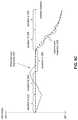
- FIG. 4illustrates an example observed trajectory
- FIG. 5Aillustrates example predicted trajectories.
- FIG. 5Billustrates an example smoothed trajectory
- FIG. 5Cillustrates an example capture trajectory
- FIG. 6Aillustrates example optical field of view and capture field of view.
- FIG. 6Billustrates example orientations of a capture field of view with respect to an optical field of view.
- FIG. 1illustrates a system 10 for stabilizing videos.
- the system 10may include one or more of a processor 11 , an interface 12 (e.g., bus, wireless interface), an electronic storage 13 , and/or other components.
- the system 10may include one or more image sensors, one or more position sensors, and/or other components. Images with an optical field of view may be captured by an image capture device during a capture duration. Image information defining the images, position information characterizing positions of the image capture device at different moments within the capture duration, and/or other information may be obtained during the capture duration. Image information, position information, and/or other information may be obtained by the processor 11 . An observed trajectory of the image capture device during the capture duration may be determined based on the position information and/or other information.
- the observed trajectorymay reflect the positions of the image capture device at different moments within the capture duration.
- the observed trajectorymay include a first portion corresponding to a first moment within the capture duration and a second portion corresponding to a second moment subsequent to the first moment within the capture duration.
- a capture trajectory of the image capture devicemay be determined based on a subsequent portion of the observed trajectory and/or other information such that a portion of the capture trajectory corresponding to the first portion of the observed trajectory may be determined based on the second portion of the observed trajectory.
- the capture trajectorymay have smoother changes in the positions of the image capture device than the observed trajectory. Orientations of the capture field of view for the images with respect to the optical field of view of the images may be determined based on the capture trajectory of the image capture device and/or other information.
- Video contentmay be generated based on visual content of the images within the capture field of view and/or other information.
- the electronic storage 13may be configured to include electronic storage medium that electronically stores information.
- the electronic storage 13may store software algorithms, information determined by the processor 11 , information received remotely, and/or other information that enables the system 10 to function properly.
- the electronic storage 13may store information relating to images, image information, information relating to image capture device, information relating to optical element, information relating to image sensor, information relating to position sensor, position information, information relating to observed trajectory of the image capture device, information relating to capture trajectory of the image capture device, information relating to optical field of view, information relating to capture field of view, information relating to video content, and/or other information.
- the processor 11may be configured to provide information processing capabilities in the system 10 .
- the processor 11may comprise one or more of a digital processor, an analog processor, a digital circuit designed to process information, a central processing unit, a graphics processing unit, a microcontroller, an analog circuit designed to process information, a state machine, and/or other mechanisms for electronically processing information.
- the processor 11may be configured to execute one or more machine-readable instructions 100 to facilitate stabilizing videos.
- the machine-readable instructions 100may include one or more computer program components.
- the machine-readable instructions 100may include one or more of an observed trajectory component 102 , a capture trajectory component 104 , an orientation component 106 , a generation component 108 , and/or other computer program components.
- Images with an optical field of viewmay be captured by an image capture device during a capture duration.
- An optical field of view of imagemay define a field of view of a scene captured within the image.
- a capture durationmay be measured/defined in terms of time durations and/or frame numbers. For example, images may be captured during a capture duration of 60 seconds, and/or from one point in time to another point in time. Images may be captured during a capture duration including capture of 1800 images. If the images are captured at 30 images/second, then the capture duration may correspond to 60 seconds. Other capture durations are contemplated.
- the system 10may be remote from the image capture device or local to the image capture device. One or more portions of the image capture device may be remote from or a part of the system 10 . One or more portions of the system 10 may be remote from or a part of the image capture device.
- one or more components of the system 10may be carried by a housing, such as a housing of an image capture device.
- a housingsuch as a housing of an image capture device.
- image sensor(s) and position sensor(s) of the system 10may be carried by the housing of the image capture device.
- the housingmay carry other components, such as the processor 11 and/or one or more optical elements.
- An image capture devicemay refer to a device for recording visual information in the form of images, videos, and/or other media.
- An image capture devicemay be a standalone device (e.g., camera) or may be part of another device (e.g., part of a smartphone).
- FIG. 3illustrates an example image capture device 302 .
- the image capture device 302may include a housing 312 , and the housing 312 may carry (be attached to, support, hold, and/or otherwise carry) an optical element 304 , an image sensor 306 , a position sensor 308 , a processor 310 , and/or other components. Other configurations of image capture devices are contemplated.
- the optical element 304may include instrument(s), tool(s), and/or medium that acts upon light passing through the instrument(s)/tool(s)/medium.
- the optical element 304may include one or more of lens, mirror, prism, and/or other optical elements.
- the optical element 304may affect direction, deviation, and/or path of the light passing through the optical element 304 .
- the optical element 304may be configured to guide light within an optical field of view 305 to the image sensor 306 .
- the optical field of view 305may include the field of view of a scene that is within the field of view of the optical element 304 and/or the field of view of the scene that is delivered to the image sensor 306 .
- the optical element 304may guide light within its field of view to the image sensor 306 or may guide light within a portion of its field of view to the image sensor 306 .
- the optical field of view 305may be greater than a capture field of view for generating video content.
- the image sensor 306may include sensor(s) that converts received light into output signals.
- the output signalsmay include electrical signals.
- the image sensor 306may include one or more of a charge-coupled device sensor, an active pixel sensor, a complementary metal-oxide semiconductor sensor, an N-type metal-oxide-semiconductor sensor, and/or other image sensors.
- the image sensor 306may generate output signals conveying information that defines one or more images (e.g., video frames of a video).
- the image sensor 306may be configured to generate an image output signal based on light that becomes incident thereon during a capture duration.
- the image output signalmay convey image information that defines images with the optical field of view.
- the position sensor 308may include sensor(s) that converts experienced positions/motions into output signals.
- the output signalsmay include electrical signals.
- the position sensor 308may refer to a set of position sensors, which may include one or more inertial measurement units, one or more accelerometers, one or more gyroscopes, and/or other position sensors.
- the position sensor 308may generate output signals conveying information that characterizes positions of the position sensor 308 and/or device(s) carrying the position sensor 308 .
- the position sensor 308may be configured to generate a position output signal based on positions of the housing/image capture device during the capture duration.
- the position output signalmay convey position information that characterizes positions of the housing 312 at different moments (points in time, time durations) within the capture duration.
- the position informationmay characterize positions of the housing 312 based on specific translational and/or rotational positions of the housing 312 and/or based on changes in translational and/or rotational positions of the housing 312 as a function of progress through the capture duration. That is, the position information may characterize translational and/or rotational positions of the housing 312 and/or changes in translational and/or rotational positions (motion) of the housing 312 (e.g., direction, amount, velocity, acceleration) during the capture duration.
- the position informationmay be determined based on signals generated by the position sensor 308 and independent of the information/signals generated by the image sensor 306 . That is, position information may be determined without using images/videos generated by the image sensor 306 . Use of images/videos to determine positions/motions of the housing 312 /image capture device 302 may be computationally expensive in terms of processing power, processing time, and/or battery consumption. Using the information/signals from the position sensor 308 to determine positions/motions of the housing 312 /image capture device 302 may be computationally cheaper.
- positions/motions of the housing 312 /image capture device 302are determined from the information/signals from the position sensor 308 than the information/signals from the image sensor 306 .
- the position information determined independent of the image informationmay be used to determine the trajectory of the housing 312 /image capture device 302 during the capture duration.
- the processor 310may include one or more processors (logic circuitry) that provide information processing capabilities in the image capture device 302 .
- the processor 310may provide one or more computing functions for the image capture device 302 .
- the processor 310may operate/send command signals to one or more components of the image capture device 302 to operate the image capture device 302 .
- the processor 310may facilitate operation of the image capture device 302 in capturing image(s) and/or video(s), facilitate operation of the optical element 304 (e.g., change how light is guided by the optical element 304 ), and/or facilitate operation of the image sensor 306 (e.g., change how the received light is converted into information that defines images/videos and/or how the images/videos are post-processed after capture).
- the processor 310may obtain information from the image sensor 306 and/or the position sensor 308 , and/or facilitate transfer of information from the image sensor 306 and/or the position sensor 308 to another device/component.
- the processor 310may be remote from the processor 11 or local to the processor 11 .
- One or more portions of the processor 310may be part of the processor 11 and/or one or more portions of the processor 10 may be part of the processor 310 .
- the processor 11may be configured to obtain information to facilitate stabilizing videos.
- Obtaining informationmay include one or more of accessing, acquiring, analyzing, determining, examining, identifying, loading, locating, opening, receiving, retrieving, reviewing, storing, and/or otherwise obtaining the information.
- the processor 11may obtain information from one or more locations.
- the processor 11may obtain information from a storage location, such as the electronic storage 13 , electronic storage of information and/or signals generated by one or more sensors, electronic storage of a device accessible via a network, and/or other locations.
- the processor 11may obtain information from one or more hardware components (e.g., an image sensor, a position sensor) and/or one or more software components (e.g., software running on a computing device).
- the processor 11may obtain image information defining images with an optical field of view, position information characterizing positions of an image capture device at different moments within a capture duration, and/or other information.
- image informationmay be obtained during acquisition of the images and/or after acquisition of the images by an image capture device.
- image information, position information, and/or other informationmay be obtained while the images are being captured by an image capture device and/or after the images have been captured and stored in memory (e.g., the electronic storage 13 ).
- the observed trajectory component 102may be configured to determine an observed trajectory of the image capture device/housing of the image capture device during the capture duration based on the position information and/or other information. The determination of the observed trajectory may be referred to as trajectory generation/observed trajectory generation.
- the observed trajectorymay refer to one or more paths and/or progression followed by the image capture device/housing during the capture duration.
- the observed trajectorymay reflect positions of the image capture device/housing of the image capture device at different moments within the capture duration.
- the positions of the image capture device/housing of the image capture devicemay include rotational positions (e.g., rotations about one or more axis of the image capture device) and/or translational positions of the image capture device/housing of the image capture device.
- the observed trajectory component 102may determine an observed trajectory of the image capture device/housing of the image capture device during the capture duration based on the position information characterizing specific translational and/or rotational positions of the image capture device/housing and/or changes in translational and/or rotational positions of the image capture device/housing as a function of progress through the capture duration.
- the observed trajectorymay include different portions corresponding to different moments within the capture duration.
- the observed trajectorymay include a first portion corresponding to a first moment within the capture duration and a second portion corresponding to a second moment within the capture duration.
- the second momentmay be subsequent to the first moment within the capture duration.
- FIG. 4illustrates an example observed trajectory of an image capture device.
- the observed trajectorymay include an observed yaw trajectory 400 of the image capture device.
- the observed yaw trajectory 400may reflect yaw angle positions (e.g., rotational positions defined with respect to a yaw axis, rotation to the left or right) of the image capture device/housing of the image capture device at different moments within the capture duration.
- the observed yaw trajectory 400may show that the image capture device was rotated in a negative yaw direction, rotated in a positive yaw direction, rotated back in the forward configuration, then rotated in the negative yaw direction.
- the image capture deviceduring capture of images, may have been rotated to the right, then to the left, to the front, then to the right.
- Other types of observed trajectorye.g., pitch trajectory, roll trajectory, translational trajectory
- Generating a video based on the images captured along the observed yaw trajectory 400may be undesirable. For example, generating a video based on the images captured along the observed yaw trajectory 400 may result in a video with footage that is shaky and/or that appears to include unintended camera motion. For instance, sharp/quick changes in the yaw angle positions of the image capture device may result in abrupt changes in the direction of visuals within the video (e.g., quick left or right camera motion). Multiple changes in the yaw angle positions of the image capture device may result in a footage that is changing the direction of view (e.g., to the right, to the left, to the front, to the right).
- Stabilization of such videosmay include using smaller visual content portions of the images to provide a punch-out view of the images that creates a more stable view than when generating videos by using the entire visual content of the images.
- stabilizationmay be provided by creating a stabilized trajectory over the capture duration and determining the punch-outs from the images based on the stabilized trajectory.
- a punch-out of an imagemay refer to one or more portions of the image that is used for presentation, such as a cut-out of the image or a cropped portion of the image.
- a punch-out of an imagemay include one or more visual portions of the image presented on a display and/or one or more visual portion portions of the image used to generate video frames of video content.
- some stabilization techniquesmay not preserve the intent of the user that captured the images.
- videosmay be stabilized by predicting positions/motions of the camera based on past positions/motions. For example, when attempting to determine the location and/or shape of the punch-out for an image captured at a given moment within the capture duration, the positions/motions of the image capture device preceding that moment may be used to determine how to position/shape the punch-out to create a stabilized view. Such use of “past” position/motion information may conflict with the motion intended by the user of the image capture device.
- the rotation of the image capture device to the right, then to the left, and then to the frontmay be the result of the image capture device being unintentionally rotated to the right, the user overcorrecting the rotation to the left, and then rotating the image capture device to the right to a front-facing direction. Determining punch-out of the images using “past” position/motion information may result in a predicted trajectory as shown in FIG. 5A .
- a predicted yaw trajectory A 512may be predicted for duration B 504 .
- a predicted yaw trajectory B 514which continues the smaller rotation to the right, may be predicted for duration D 508 .
- the predicted yaw trajectory A 512may be in opposite direction of the actual motion of the image capture device during duration B 504 , and the predicted yaw trajectory B 514 may be off from the observed yaw trajectory by a large margin.
- Such discrepancy between the observed yaw trajectory and the predicted yaw trajectorymay result in the images not including enough visual information (e.g., pixels) to account for the attempted stabilized and/or the punch-out location/shape.
- videosmay be stabilized by smoothing the observed changes in positions/motions of the image capture device.
- a low-pass filtermay be applied to the observed trajectory to smooth out the abrupt rotational and/or translational changes in the positions/motions of the image capture device.
- a smoothed yaw trajectory 516may be determined.
- the smoothed yaw trajectory 516may have smoother changes in the positions/motions of the image capture device than the observed yaw trajectory.
- such smoothmay not take into account how the positions/motions changes during the capture duration and may not preserve the intent of the user that captured the images.
- the videomay still include footage that is changing the direction of view to the right, then to left, to the front, and then to the right in a non-continuous motion (e.g., rotating to the right to a certain angle, holding that position for a time, then rotating to the right, then back a little to the left, and then to the right again).
- a non-continuous motione.g., rotating to the right to a certain angle, holding that position for a time, then rotating to the right, then back a little to the left, and then to the right again).
- the capture trajectory component 104may be configured to determine a capture trajectory of the image capture device/housing of the image capture device based on a subsequent portion of the observed trajectory and/or other information.
- the determination of the capture trajectorymay be referred to as trajectory generation/capture trajectory generation.
- the capture trajectorymay refer to one or more paths and/or progression to be used in determining which portions of the visual content of the images (punch-outs) may be used to generate a video.
- the capture trajectorymay reflect actual and/or virtual positions of the image capture device/housing of the image capture device at different moments within the capture duration. An actual position may refer to a position that was taken by the image capture device/housing of the image capture.
- a virtual positionmay refer to a position that was not taken by the image capture device/housing of the image capture.
- a virtual positionmay be offset (rotationally and/or translationally) from the actual position of the image capture device/housing of the image capture device.
- the capture trajectorymay have smoother changes in the positions of the image capture device/housing of the image capture device than the observed trajectory. That is, the capture trajectory may have less jitters (slight irregular movement/variation), less abrupt changes, and/or less discontinuous changes in the positions of the image capture device/housing of the image capture device than the observed trajectory.
- Determining a capture trajectory (capture trajectory generation) based on a subsequent portion of an observed trajectorymay include determining a portion of the capture trajectory corresponding to a given moment within the capture duration based on one or more portions of the observed trajectory corresponding to one or more subsequent moments (moment(s) past the given moment) within the capture duration. That is, the capture trajectory component 104 may “look ahead” in time to determine a portion of the capture trajectory. A look ahead may include use of one or more subsequent portions of an observed trajectory to determine a preceding portion of the capture trajectory. Such generation of trajectory may be referred to as a look head trajectory generation. A subsequent moment within the duration may be adjacent to the given moment or not adjacent to the given moment.
- Using the subsequent portion(s) of the observed trajectorymay enable the capture trajectory component 104 to determine a capture trajectory that preserves a user's intended motion for the image capture device.
- the user's intended motionmay refer to the motion of the image capture device that the user planned/meant to carry out.
- the positions/motions of the image capture device in the “future”may be analyzed (look ahead) to determine whether particular position(s)/motion(s) of the image capture device at a moment is an intended motion or an unintended motion (e.g., shaking due to vibration, rotation due to bumping/mishandling the image capture device). For example, when determining the capture trajectory for a moment (e.g., corresponding to the 1000th video frame) within the capture duration, the position(s)/motion(s) of the image capture device for a duration subsequent to the moment (e.g., corresponding to the next 30 video frames) may be analyzed to determine whether the position/motion of the image capture device at the moment was intended or not.
- an intended motione.g., shaking due to vibration, rotation due to bumping/mishandling the image capture device.
- the capture trajectory component 104may determine a capture trajectory of the image capture device/housing of the image capture device further based on one or more prior portions of the observed trajectory.
- the past position/motion information of the image capture devicemay supply context for the intended motion.
- FIG. 5Cillustrates an example capture trajectory determined by the capture trajectory component 104 .
- the capture trajectorymay include a capture yaw trajectory 532 .
- the capture yaw trajectory 532may reflect yaw angle positions (e.g., rotational positions defined with respect to a yaw axis, rotation to the left or right) of the image capture device/housing of the image capture device to be used in determining which portions of the visual content of the images (punch-outs) may be used to generate a video.
- yaw angle positionse.g., rotational positions defined with respect to a yaw axis, rotation to the left or right
- the capture yaw trajectory 532may include a zero-rotation about the yaw axis (front-direction) for durations 522 , 524 , 526 and then a smooth rotation to the right for durations 528 , 530 .
- Other types of capture trajectorye.g., capture pitch trajectory, capture roll trajectory, capture translational trajectory are contemplated.
- the capture yaw trajectory 532may be determined such that a portion of the capture yaw trajectory 532 corresponding to the portion of the observed yaw trajectory 400 is determined based on a subsequent portion of the observed yaw trajectory 400 .
- the portion of the capture yaw trajectory 532 for one or more portions of the duration A 522may be determined based on the portion(s) of the observed yaw trajectory 400 within the duration B 524 and/or the duration C 526 (look ahead to the duration B 524 and/or the duration C 526 ).
- the portion(s) of the observed yaw trajectory 400 for the duration B 524 and/or the duration C 526may be used to determine in what direction and/or by what amount the capture yaw trajectory 532 for portion(s) of the duration A 522 may differ from the observed yaw trajectory 400 .
- the capture yaw trajectory 532may be determined based on subsequent portion(s) of the observed trajectory 400 such that the capture yaw trajectory 532 preserves a user's intended motion for the image capture device.
- the capture trajectory component 104may determine that the rotation of the image capture device to the right and left during durations 522 , 524 were unintended motions (e.g., the image capture device being unintentionally rotated to the right and the user overcorrecting the rotation to the left), and may determine the capture yaw trajectory 532 to be directed to the front during durations 522 , 524 .
- the capture trajectory component 104may determine that the staggered rotation of the image capture device to the right during durations 528 , 530 included unintended motions (non-continuous rotation to the right), and may determine the capture yaw trajectory 532 to include continuous rotation to the right during durations 528 , 530 .
- Other determinations of capture trajectoryare contemplated.
- the capture trajectorymay be determined based on minimization of a rotational velocity of the image capture device/housing of the image capture device and a rotational acceleration of the image capture device/housing of the image capture device while respecting a set of constraints. For example, the capture trajectory may be determined by generating a smooth path that respects the set of constraints, rather than by modifying the observed trajectory.
- a smooth path defining yaw angle position, pitch angle position, and/or roll angle positionmay be generated by finding a path of the image capture device/housing of the image capture device that minimizes a combination of a time derivative, a second time derivative, and/or other time derivative(s) of the yaw angle position, pitch angle position, and/or roll angle position while respecting the set of constraints:
- one or more of the portions of the minimization calculationmay be changed.
- one or more portions of the minimization calculatione.g., the first time derivative
- other portion(s) of the minimization calculatione.g., the second time derivative
- information on high frequencies (jitters) of image capturemay be used to improve visual characteristics of generated video content.
- Certain portion of high frequencies in the inputmay be kept based on the image capture configuration, such as exposure start time and exposure duration time, the position information (e.g., position sensor readings), and/or other information.
- motion of the image capture device/image sensor during a frame exposuremay be analyzed and used to generate/modify a capture trajectory that minimizes inter-frame motion (e.g., smooths inter-frame motion) while preserving the intra-frame motion, which may contain the high frequencies. This may provide for improved visual characteristics of the generated video content, such as by compensating for motion blur and/or lowlight image capture conditions.
- image capturemay not happen instantaneously. Rather, it may take a certain amount of time for image sensor pixel sites to gather light. This may lead to splitting of the image sensor motion in time in two phases: inter-frame motion which may not be captured and may be suppressed, and intra-frame motion which may be “encrusted” in the image and may not be removed.
- Better visual characteristicse.g., impression
- the capture trajectorymay move/follow in the same direction and with the same speed as during the frame exposure phase, so that its motion is aligned with the motion blur in the image.
- the set of constraintsmay include one or more constraints that provide limitations/restrictions/rules on how the smooth path is generated.
- the set of constraintsmay include a margin constraint that provide limitation(s)/restriction(s)/rule(s) on how far from the observed trajectory the smooth path may be generated.
- the margin constraintmay be determined based on a difference between the optical field of view and the capture field of view, and/or other information.
- the optical field of viewmay refer to the field of view of a scene captured within the image. That is, the optical field of view may refer to the spatial extent/angle of the scene captured within the image.
- the capture field of viewmay refer to the field of view used to generate a video based on visual content of the images. That is, a video may be generated based on visual content of the images within the capture field of view.
- the capture field of viewmay be defined in terms of shape and/or size.
- FIG. 6Aillustrates an example optical field of view 602 and an example capture field of view 604 for an image A 600 .
- the image A 600may include capture of a scene within an angle defined by the optical field of view 602 .
- the capture field of view 604may provide a punch-out of the image A 600 to be used for video generation.
- the amount and/or direction from which the smooth path may deviate from the observed trajectorymay depend on the difference between the optical field of view 602 and the capture field of view 604 .
- the difference between the optical field of view 602 and the capture field of view 604(e.g., 10%) may define a margin 606 within which the capture field of view 604 may move with respect to the optical field of view 602 .
- a margin 606within which the capture field of view 604 may move with respect to the optical field of view 602 .
- a capture field of view 614may be rotated with respect to the optical field of view 612 while not going beyond the pixels captured within an image B 610 , and a capture field of view 624 may be laterally moved with respect to a optical field of view 622 while not going beyond the pixels captured within an image C 620 .
- the larger margin 606may result in waste of pixel space and computing resources (e.g., processor power and/or battery consumption to capture images with larger optical field of view than needed to generate a video).
- the set of constraintsmay include a trajectory constraint that provide limitation(s)/restriction(s)/rule(s) on how the smooth path may be generated based on subsequent portions of the observed trajectory.
- the trajectory constraintmay be determined based on a subsequent portion of the observed trajectory and/or other information. That is, the trajectory constraint may include one or more constraints relating to shape of the observed trajectory in the “future.” The trajectory constraint may preserve the intended motion for the image capture device in the generated path.
- the set of constraintsmay include a target constraint that provide limitation(s)/restriction(s)/rule(s) on how the smooth path may be generated based on a target within the images.
- a targetmay refer to a person, an object, and/or a thing that may be selected for inclusion in a video.
- the images captured by the image capture devicemay include one or more view of a person (e.g., a person of interest) and a user may wish to create a video that includes the person.
- the target constraintmay include one or more constraints relating to the location of the target within the images such that the images are stabilized around the location of the target within the images. That is, the target constraint may affect the generation of the smooth path so that the target is within one or more of the punch-outs for the images. Other constraints are contemplated.
- the orientation component 106may be configured to determine orientations of the capture field of view for the images with respect to the optical field of view of the images based on the capture trajectory of the image capture device/housing of the image capture device and/or other information.
- the orientations of the capture field of view for the images with respect to the optical field of view of the imagesmay determine which portions of the visual content of the images (punch-outs) may be used to generate a video. That is, the orientation component 106 may determine how the punch-outs for the images may be oriented with respect to the capture field of view for the images.
- the capture trajectorymay be used to determine how much and in what direction the capture field of view is rotated with respect to the optical field of view.
- the orientation component 106may determine how the punch-outs for the images may be laterally and/or vertically positioned with respect to the capture field of view for the images.
- the capture trajectorymay determine how much and in what direction the capture field of view is rotated with respect to the optical field of view.
- the capture trajectorymay be used to determine how much and in what direction the capture field of view is laterally/vertically positioned with respect to the optical field of view.
- the orientation component 106may determine the orientation of the capture field of view 614 with respect to the optical field of view 612 for the image B 610 based on the capture trajectory at a particular moment.
- the capture field of view 614may be oriented with respect to the optical field of view 612 to provide a punch-out of the image B 610 that is stable with respect to a prior and/or next punch-out of the images (e.g., stable with the punch-out of the image A 600 using the capture field of view 604 for the image A 600 , shown in FIG. 6A ).
- the orientation component 106may determine the orientation of the capture field of view 624 with respect to the optical field of view 622 for the image C 620 based on the capture trajectory at a particular moment.
- the capture field of view 624may be oriented with respect to the optical field of view 622 to provide a punch-out of the image C 620 that is stable with respect to a prior and/or next punch-out of the images (e.g., stable with the punch-out of the image B 610 using the capture field of view 614 for the image B 610 ).
- the generation component 108may be configured to generate video content based on visual content of the images within the capture field of view and/or other information.
- Video contentmay refer media content that may be consumed as one or more videos/video clips.
- Video contentmay include one or more videos/video clips stored in one or more formats/containers, and/or other video content.
- a formatmay refer to one or more ways in which the information defining video content is arranged/laid out (e.g., file format).
- a containermay refer to one or more ways in which information defining video content is arranged/laid out in association with other information (e.g., wrapper format).
- Video contentmay define visual content viewable as a function of progress through a progress length of the video content.
- Video contentmay include video frames that define visual content. That is, visual content of the video content may be included within video frames of the video content.
- the video frames of the video contentmay be determined based on visual content of the images within the capture field of view and/or other information.
- the video frames of the video contentmay be determined based on a punch-out of the images in accordance with the capture trajectory, the capture field of view, and/or other information.
- the video frames of the video contentmay be determined based on the visual content of the image A 600 within the capture field of view 604 , the visual content of the image B 610 within the capture field of view 614 , the visual content of the image C 620 within the capture field of view 624 , and/or other information.
- Such determination of visual content of images for inclusion in video contentmay effectuate stabilization of the video content.
- the video frames of the video contentmay be determined based on warping of images (e.g., one or more portions of the visual content of the images).
- the warping of the imagesmay provide for different perspectives of content captured within the images, with the different perspectives corresponding to how the content would have look had the images been captured from the image capture device on the capture trajectory.
- one or more of the images and/or one or more of the portions of images used to generate video contentmay be stored in a buffer (e.g., 1s buffer).
- the buffermay be used to store images/portions of images including visual content that will be included in the visual content and/or images/portions of images including visual content that will be transformed (e.g., warped) for inclusion in the visual content.
- the buffermay be used to store image information, position information, and/or other information for look ahead and/or trajectory generation.
- the buffermay be used to store images for which trajectory generation is being performed using look ahead. After corresponding portion of the capture trajectory is generated, the relevant portions of the images (visual content of the images within the capture field of view) in the buffer may be used to generate the video content.
- the video content generated by the generation component 108may be defined by video information.
- Video information defining video contentmay define an encoded version/copy of the video content and/or instructions for rendering the video content.
- the video informationmay define an encoded version/copy of the video content
- the video information(e.g., video file) may be opened in a video player for presentation of the video content.
- the video informationmay define instructions to render the video content for presentation.
- the video informationmay define a director track that includes information as to which visual portions of the images should be included within the presentation of the video content.
- the director trackmay include information on the location and/or shape of the punch-out of images to be used to as a function progress through the video content to provide a stabilized view of the images.
- a video playermay use the director track to retrieve the relevant visual portions of the images when the video content is opened/to be presented.
- the generation component 108may be configured effectuate storage of the video information and/or other information in one or more storage media.
- the video informationmay be stored in the electronic storage 13 , remote storage locations (storage media located at/accessible through a server), and/or other locations.
- the generation component 108may effectuate storage of the video information through one or more intermediary devices.
- the processor 11may be located within a computing device without a connection to the storage device (e.g., the computing device lacks WiFi/cellular connection to the storage device).
- the generation component 108may effectuate storage of the video information through another device that has the necessary connection (e.g., the computing device using a WiFi/cellular connection of a paired mobile device, such as a smartphone, tablet, laptop, to store information in one or more storage media).
- another devicethat has the necessary connection
- the computing device using a WiFi/cellular connection of a paired mobile devicesuch as a smartphone, tablet, laptop
- Other storage locations for and storage of the video informationare contemplated.
- While the description hereinmay be directed to images and videos, one or more other implementations of the system/method described herein may be configured for other types media content.
- Other types of media contentmay include one or more of audio content (e.g., music, podcasts, audiobooks, and/or other audio content), multimedia presentations, images, slideshows, visual content (e.g., one or more images and/or videos), and/or other media content.
- Implementations of the disclosuremay be made in hardware, firmware, software, or any suitable combination thereof. Aspects of the disclosure may be implemented as instructions stored on a machine-readable medium, which may be read and executed by one or more processors.
- a machine-readable mediummay include any mechanism for storing or transmitting information in a form readable by a machine (e.g., a computing device).
- a tangible computer-readable storage mediummay include read-only memory, random access memory, magnetic disk storage media, optical storage media, flash memory devices, and others
- a machine-readable transmission mediamay include forms of propagated signals, such as carrier waves, infrared signals, digital signals, and others.
- Firmware, software, routines, or instructionsmay be described herein in terms of specific exemplary aspects and implementations of the disclosure, and performing certain actions.
- External resourcesmay include hosts/sources of information, computing, and/or processing and/or other providers of information, computing, and/or processing outside of the system 10 .
- any communication mediummay be used to facilitate interaction between any components of the system 10 .
- One or more components of the system 10may communicate with each other through hard-wired communication, wireless communication, or both.
- one or more components of the system 10may communicate with each other through a network.
- the processor 11may wirelessly communicate with the electronic storage 13 .
- wireless communicationmay include one or more of radio communication, Bluetooth communication, Wi-Fi communication, cellular communication, infrared communication, Li-Fi communication, or other wireless communication. Other types of communications are contemplated by the present disclosure.
- the processor 11is shown in FIG. 1 as a single entity, this is for illustrative purposes only. In some implementations, the processor 11 may comprise a plurality of processing units. These processing units may be physically located within the same device, or the processor 11 may represent processing functionality of a plurality of devices operating in coordination.
- the processor 11may be configured to execute one or more components by software; hardware; firmware; some combination of software, hardware, and/or firmware; and/or other mechanisms for configuring processing capabilities on the processor 11 .
- FIG. 1it should be appreciated that although computer components are illustrated in FIG. 1 as being co-located within a single processing unit, in implementations in which processor 11 comprises multiple processing units, one or more of computer program components may be located remotely from the other computer program components.
- While computer program componentsare described herein as being implemented via processor 11 through machine-readable instructions 100 , this is merely for ease of reference and is not meant to be limiting. In some implementations, one or more functions of computer program components described herein may be implemented via hardware (e.g., dedicated chip, field-programmable gate array) rather than software. One or more functions of computer program components described herein may be software-implemented, hardware-implemented, or software and hardware-implemented
- processor 11may be configured to execute one or more additional computer program components that may perform some or all of the functionality attributed to one or more of computer program components described herein.
- the electronic storage media of the electronic storage 13may be provided integrally (i.e., substantially non-removable) with one or more components of the system 10 and/or removable storage that is connectable to one or more components of the system 10 via, for example, a port (e.g., a USB port, a Firewire port, etc.) or a drive (e.g., a disk drive, etc.).
- a porte.g., a USB port, a Firewire port, etc.
- a drivee.g., a disk drive, etc.
- the electronic storage 13may include one or more of optically readable storage media (e.g., optical disks, etc.), magnetically readable storage media (e.g., magnetic tape, magnetic hard drive, floppy drive, etc.), electrical charge-based storage media (e.g., EPROM, EEPROM, RAM, etc.), solid-state storage media (e.g., flash drive, etc.), and/or other electronically readable storage media.
- the electronic storage 13may be a separate component within the system 10 , or the electronic storage 13 may be provided integrally with one or more other components of the system 10 (e.g., the processor 11 ).
- the electronic storage 13is shown in FIG. 1 as a single entity, this is for illustrative purposes only.
- the electronic storage 13may comprise a plurality of storage units. These storage units may be physically located within the same device, or the electronic storage 13 may represent storage functionality of a plurality of devices operating in coordination.
- FIG. 2illustrates method 200 for stabilizing videos.
- the operations of method 200 presented beloware intended to be illustrative. In some implementations, method 200 may be accomplished with one or more additional operations not described, and/or without one or more of the operations discussed. In some implementations, two or more of the operations may occur substantially simultaneously.
- method 200may be implemented in one or more processing devices (e.g., a digital processor, an analog processor, a digital circuit designed to process information, a central processing unit, a graphics processing unit, a microcontroller, an analog circuit designed to process information, a state machine, and/or other mechanisms for electronically processing information).
- the one or more processing devicesmay include one or more devices executing some or all of the operation of method 200 in response to instructions stored electronically on one or more electronic storage mediums.
- the one or more processing devicesmay include one or more devices configured through hardware, firmware, and/or software to be specifically designed for execution of one or more of the operation of method 200 .
- an image output signalmay be generated.
- the image output signalmay convey image information that defines images with an optical field of view.
- operation 201may be performed by a component the same as or similar to the image sensor 306 (Shown in FIG. 3 and described herein).
- a position output signalmay be generated.
- the position output signalmay convey position information that characterizes positions of an image capture device at different moments within a capture duration.
- operation 202may be performed by a processor component the same as or similar to the positions sensor 308 (Shown in FIG. 3 and described herein).
- an observed trajectory of the image capture device during the capture durationmay be determined based on the position information.
- operation 203may be performed by a processor component the same as or similar to the observed trajectory component 102 (Shown in FIG. 1 and described herein).
- a capture trajectory of the image capture devicemay be determined based on a subsequent portion of the observed trajectory.
- operation 204may be performed by a processor component the same as or similar to the capture trajectory component 104 (Shown in FIG. 1 and described herein).
- orientations of a capture field of view for the imagemay be determined with respect to the optical field of view based on the capture trajectory.
- operation 205may be performed by a processor component the same as or similar to the orientation component 106 (Shown in FIG. 1 and described herein).
- video contentmay be generated based on visual content of the images within the capture field of view.
- operation 206may be performed by a processor component the same as or similar to the generation component 108 (Shown in FIG. 1 and described herein).
Landscapes
- Engineering & Computer Science (AREA)
- Multimedia (AREA)
- Signal Processing (AREA)
- Studio Devices (AREA)
- Closed-Circuit Television Systems (AREA)
- Air Bags (AREA)
- Image Processing (AREA)
Abstract
Description
Claims (20)
Priority Applications (6)
| Application Number | Priority Date | Filing Date | Title |
|---|---|---|---|
| US16/548,453US10574894B2 (en) | 2018-05-18 | 2019-08-22 | Systems and methods for stabilizing videos |
| US16/787,693US11025824B2 (en) | 2018-05-18 | 2020-02-11 | Systems and methods for stabilizing videos |
| US17/334,150US11363197B2 (en) | 2018-05-18 | 2021-05-28 | Systems and methods for stabilizing videos |
| US17/837,013US11696027B2 (en) | 2018-05-18 | 2022-06-09 | Systems and methods for stabilizing videos |
| US18/345,229US12256147B2 (en) | 2018-05-18 | 2023-06-30 | Systems and methods for stabilizing videos |
| US19/082,025US20250220306A1 (en) | 2018-05-18 | 2025-03-17 | Systems and methods for stabilizing videos |
Applications Claiming Priority (5)
| Application Number | Priority Date | Filing Date | Title |
|---|---|---|---|
| US201862673388P | 2018-05-18 | 2018-05-18 | |
| US15/987,786US10587807B2 (en) | 2018-05-18 | 2018-05-23 | Systems and methods for stabilizing videos |
| US16/150,066US10341564B1 (en) | 2018-05-18 | 2018-10-02 | Systems and methods for stabilizing videos |
| US16/418,203US10587808B2 (en) | 2018-05-18 | 2019-05-21 | Systems and methods for stabilizing videos |
| US16/548,453US10574894B2 (en) | 2018-05-18 | 2019-08-22 | Systems and methods for stabilizing videos |
Related Parent Applications (1)
| Application Number | Title | Priority Date | Filing Date |
|---|---|---|---|
| US16/418,203ContinuationUS10587808B2 (en) | 2018-05-18 | 2019-05-21 | Systems and methods for stabilizing videos |
Related Child Applications (1)
| Application Number | Title | Priority Date | Filing Date |
|---|---|---|---|
| US16/787,693ContinuationUS11025824B2 (en) | 2018-05-18 | 2020-02-11 | Systems and methods for stabilizing videos |
Publications (2)
| Publication Number | Publication Date |
|---|---|
| US20190379834A1 US20190379834A1 (en) | 2019-12-12 |
| US10574894B2true US10574894B2 (en) | 2020-02-25 |
Family
ID=67069456
Family Applications (9)
| Application Number | Title | Priority Date | Filing Date |
|---|---|---|---|
| US15/987,786ActiveUS10587807B2 (en) | 2018-05-18 | 2018-05-23 | Systems and methods for stabilizing videos |
| US16/150,066ActiveUS10341564B1 (en) | 2018-05-18 | 2018-10-02 | Systems and methods for stabilizing videos |
| US16/418,203ActiveUS10587808B2 (en) | 2018-05-18 | 2019-05-21 | Systems and methods for stabilizing videos |
| US16/548,453ActiveUS10574894B2 (en) | 2018-05-18 | 2019-08-22 | Systems and methods for stabilizing videos |
| US16/787,693ActiveUS11025824B2 (en) | 2018-05-18 | 2020-02-11 | Systems and methods for stabilizing videos |
| US17/334,150ActiveUS11363197B2 (en) | 2018-05-18 | 2021-05-28 | Systems and methods for stabilizing videos |
| US17/837,013ActiveUS11696027B2 (en) | 2018-05-18 | 2022-06-09 | Systems and methods for stabilizing videos |
| US18/345,229ActiveUS12256147B2 (en) | 2018-05-18 | 2023-06-30 | Systems and methods for stabilizing videos |
| US19/082,025PendingUS20250220306A1 (en) | 2018-05-18 | 2025-03-17 | Systems and methods for stabilizing videos |
Family Applications Before (3)
| Application Number | Title | Priority Date | Filing Date |
|---|---|---|---|
| US15/987,786ActiveUS10587807B2 (en) | 2018-05-18 | 2018-05-23 | Systems and methods for stabilizing videos |
| US16/150,066ActiveUS10341564B1 (en) | 2018-05-18 | 2018-10-02 | Systems and methods for stabilizing videos |
| US16/418,203ActiveUS10587808B2 (en) | 2018-05-18 | 2019-05-21 | Systems and methods for stabilizing videos |
Family Applications After (5)
| Application Number | Title | Priority Date | Filing Date |
|---|---|---|---|
| US16/787,693ActiveUS11025824B2 (en) | 2018-05-18 | 2020-02-11 | Systems and methods for stabilizing videos |
| US17/334,150ActiveUS11363197B2 (en) | 2018-05-18 | 2021-05-28 | Systems and methods for stabilizing videos |
| US17/837,013ActiveUS11696027B2 (en) | 2018-05-18 | 2022-06-09 | Systems and methods for stabilizing videos |
| US18/345,229ActiveUS12256147B2 (en) | 2018-05-18 | 2023-06-30 | Systems and methods for stabilizing videos |
| US19/082,025PendingUS20250220306A1 (en) | 2018-05-18 | 2025-03-17 | Systems and methods for stabilizing videos |
Country Status (4)
| Country | Link |
|---|---|
| US (9) | US10587807B2 (en) |
| EP (2) | EP4224877B1 (en) |
| CN (1) | CN112136314B (en) |
| WO (1) | WO2019222029A1 (en) |
Cited By (7)
| Publication number | Priority date | Publication date | Assignee | Title |
|---|---|---|---|---|
| US10742882B1 (en)* | 2019-05-17 | 2020-08-11 | Gopro, Inc. | Systems and methods for framing videos |
| US11064118B1 (en)* | 2019-12-18 | 2021-07-13 | Gopro, Inc. | Systems and methods for dynamic stabilization adjustment |
| US11363197B2 (en)* | 2018-05-18 | 2022-06-14 | Gopro, Inc. | Systems and methods for stabilizing videos |
| US11470254B1 (en)* | 2019-06-21 | 2022-10-11 | Gopro, Inc. | Systems and methods for assessing stabilization of videos |
| US11647289B2 (en) | 2018-09-19 | 2023-05-09 | Gopro, Inc. | Systems and methods for stabilizing videos |
| US12302000B2 (en) | 2019-08-30 | 2025-05-13 | Gopro, Inc. | Systems and methods for horizon leveling videos |
| US12302028B2 (en) | 2013-08-22 | 2025-05-13 | Gopro, Inc. | Conversion between aspect ratios in camera |
Families Citing this family (8)
| Publication number | Priority date | Publication date | Assignee | Title |
|---|---|---|---|---|
| US9756249B1 (en) | 2016-04-27 | 2017-09-05 | Gopro, Inc. | Electronic image stabilization frequency estimator |
| US9922398B1 (en) | 2016-06-30 | 2018-03-20 | Gopro, Inc. | Systems and methods for generating stabilized visual content using spherical visual content |
| NL2020562B1 (en)* | 2018-03-09 | 2019-09-13 | Holding Hemiglass B V | Device, System and Methods for Compensating for Partial Loss of Visual Field |
| US11393125B1 (en)* | 2019-12-09 | 2022-07-19 | Gopro, Inc. | Systems and methods for dynamic optical medium calibration |
| JP2023534243A (en) | 2020-07-17 | 2023-08-08 | ホアウェイ・テクノロジーズ・カンパニー・リミテッド | Camera with optical image stabilization for portable electronic devices |
| CN112804444B (en)* | 2020-12-30 | 2022-08-23 | 影石创新科技股份有限公司 | Video processing method and device, computing equipment and storage medium |
| CN115131222A (en)* | 2021-03-29 | 2022-09-30 | 华为技术有限公司 | An image processing method and related equipment |
| CN119653237B (en)* | 2024-12-09 | 2025-09-30 | 西安应用光学研究所 | Frame type reverse scanning compensation control method for photoelectric platform |
Citations (56)
| Publication number | Priority date | Publication date | Assignee | Title |
|---|---|---|---|---|
| US1028479A (en) | 1911-11-20 | 1912-06-04 | Charles M Morgan | Display-card. |
| US1034156A (en) | 1909-07-02 | 1912-07-30 | Edward Sokal | Storage battery. |
| US20030160862A1 (en) | 2002-02-27 | 2003-08-28 | Charlier Michael L. | Apparatus having cooperating wide-angle digital camera system and microphone array |
| US20030210327A1 (en) | 2001-08-14 | 2003-11-13 | Benoit Mory | Display of an arrangement of a panoramic video by applying navigation commands to said panoramic video |
| US6654019B2 (en) | 1998-05-13 | 2003-11-25 | Imove, Inc. | Panoramic movie which utilizes a series of captured panoramic images to display movement as observed by a viewer looking in a selected direction |
| US20040010804A1 (en) | 1996-09-04 | 2004-01-15 | Hendricks John S. | Apparatus for video access and control over computer network, including image correction |
| US20040125133A1 (en) | 2002-12-30 | 2004-07-01 | The Board Of Trustees Of The Leland Stanford Junior University | Methods and apparatus for interactive network sharing of digital video content |
| US20060291841A1 (en) | 2005-05-26 | 2006-12-28 | Sanyo Electric Co., Ltd. | Image stabilizing device |
| WO2009047572A1 (en) | 2007-10-09 | 2009-04-16 | Analysis Systems Research High-Tech S.A. | Integrated system, method and application for the synchronized interactive play-back of multiple spherical video content and autonomous product for the interactive play-back of prerecorded events. |
| US20090278917A1 (en) | 2008-01-18 | 2009-11-12 | Lockheed Martin Corporation | Providing A Collaborative Immersive Environment Using A Spherical Camera and Motion Capture |
| US20100281375A1 (en) | 2009-04-30 | 2010-11-04 | Colleen Pendergast | Media Clip Auditioning Used to Evaluate Uncommitted Media Content |
| US20100277617A1 (en) | 2009-05-02 | 2010-11-04 | Hollinger Steven J | Ball with camera and trajectory control for reconnaissance or recreation |
| US20100299630A1 (en) | 2009-05-22 | 2010-11-25 | Immersive Media Company | Hybrid media viewing application including a region of interest within a wide field of view |
| US20110013778A1 (en) | 2004-06-23 | 2011-01-20 | Yamaha Corporation | Speaker array apparatus and method for setting audio beams of speaker array appratus |
| US8022948B2 (en) | 2008-07-29 | 2011-09-20 | International Business Machines Corporation | Image capture and buffering in a virtual world using situational measurement averages |
| US20110242352A1 (en) | 2010-03-30 | 2011-10-06 | Nikon Corporation | Image processing method, computer-readable storage medium, image processing apparatus, and imaging apparatus |
| US20120206565A1 (en) | 2011-02-10 | 2012-08-16 | Jason Villmer | Omni-directional camera and related viewing software |
| US20130002813A1 (en) | 2011-06-29 | 2013-01-03 | Vaught Benjamin I | Viewing windows for video streams |
| US20130058535A1 (en) | 2010-06-11 | 2013-03-07 | Technische Universitat Darmstadt | Detection of objects in an image using self similarities |
| US20130177168A1 (en) | 2009-12-24 | 2013-07-11 | Nokia Corporation | Apparatus |
| US20130210563A1 (en)* | 2009-05-02 | 2013-08-15 | Steven J. Hollinger | Ball with camera for reconnaissance or recreation and network for operating the same |
| US20130250047A1 (en)* | 2009-05-02 | 2013-09-26 | Steven J. Hollinger | Throwable camera and network for operating the same |
| US20130329132A1 (en) | 2012-06-06 | 2013-12-12 | Apple Inc. | Flare Detection and Mitigation in Panoramic Images |
| US20140028876A1 (en) | 2012-07-24 | 2014-01-30 | Christopher L. Mills | Image stabilization using striped output transformation unit |
| US20140039884A1 (en) | 2001-12-14 | 2014-02-06 | Microsoft Corporation | Quality improvement techniques in an audio encoder |
| WO2014042104A1 (en) | 2012-09-11 | 2014-03-20 | Ricoh Company, Ltd. | Imaging controller and imaging control method and program |
| WO2014090277A1 (en) | 2012-12-10 | 2014-06-19 | Nokia Corporation | Spatial audio apparatus |
| US20140266773A1 (en) | 2012-10-23 | 2014-09-18 | Bounce Imaging, Inc. | Remote surveillance system |
| US20140267586A1 (en) | 2012-10-23 | 2014-09-18 | Bounce Imaging, Inc. | Systems, methods and media for generating a panoramic view |
| US20140267590A1 (en) | 2013-03-15 | 2014-09-18 | Iain Richard Tyrone McCLATCHIE | Diagonal Collection of Oblique Imagery |
| US20150146014A1 (en) | 2013-11-27 | 2015-05-28 | Aptina Imaging Corporation | Imaging systems and methods for location-specific image flare mitigation |
| US20150159846A1 (en) | 2013-12-09 | 2015-06-11 | Steven J. Hollinger | Throwable light source and network for operating the same |
| US20150350548A1 (en)* | 2014-05-30 | 2015-12-03 | Apple Inc. | Video Image Stabilization |
| US20160006935A1 (en)* | 2014-07-06 | 2016-01-07 | Apple Inc. | Low Light Video Image Stabilization Strength Modulation |
| US9279983B1 (en) | 2012-10-30 | 2016-03-08 | Google Inc. | Image cropping |
| US9363569B1 (en) | 2014-07-28 | 2016-06-07 | Jaunt Inc. | Virtual reality system including social graph |
| US9374532B2 (en) | 2013-03-15 | 2016-06-21 | Google Inc. | Cascaded camera motion estimation, rolling shutter detection, and camera shake detection for video stabilization |
| US9426430B2 (en) | 2012-03-22 | 2016-08-23 | Bounce Imaging, Inc. | Remote surveillance sensor apparatus |
| US20160360109A1 (en) | 2013-11-01 | 2016-12-08 | The Lightco Inc. | Image stabilization related methods and apparatus |
| US20170041545A1 (en) | 2015-08-06 | 2017-02-09 | Invensense, Inc. | Systems and methods for stabilizing images |
| US20170070689A1 (en) | 2015-09-08 | 2017-03-09 | Apple Inc. | Automatic compensation of lens flare |
| US20170084086A1 (en) | 2015-09-22 | 2017-03-23 | Facebook, Inc. | Systems and methods for content streaming |
| US20170085964A1 (en) | 2015-09-17 | 2017-03-23 | Lens Entertainment PTY. LTD. | Interactive Object Placement in Virtual Reality Videos |
| US20170094169A1 (en) | 2014-05-27 | 2017-03-30 | Hiromi Yoshikawa | Image processing system, imaging apparatus, image processing method, and computer-readable storage medium |
| US20170142337A1 (en) | 2015-11-16 | 2017-05-18 | Google Inc. | Stabilization based on accelerometer data |
| US20170289454A1 (en) | 2016-04-04 | 2017-10-05 | Microsoft Technology Licensing, Llc | Method and apparatus for video content stabilization |
| US9787902B1 (en)* | 2016-06-10 | 2017-10-10 | Apple Inc. | Video image stabilization with enforced stabilization constraints |
| US20170359534A1 (en) | 2016-06-10 | 2017-12-14 | Apple Inc. | Mismatched Foreign Light Detection And Mitigation In The Image Fusion Of A Two-Camera System |
| US20180041705A1 (en)* | 2013-08-08 | 2018-02-08 | Canon Kabushiki Kaisha | Image shake correcting apparatus and its control method, lens barrel, optical equipment, and imaging apparatus |
| US20180048821A1 (en) | 2016-04-27 | 2018-02-15 | Gopro, Inc. | Electronic Image Stabilization Frequency Estimator |
| US20180199025A1 (en) | 2015-07-15 | 2018-07-12 | Fyusion, Inc. | Drone based capture of a multi-view interactive digital media |
| US20180220073A1 (en) | 2017-01-27 | 2018-08-02 | Invensense, Inc. | Electronic image stabilization |
| US20180324358A1 (en) | 2015-11-26 | 2018-11-08 | Sony Semiconductor Solutions Corporation | Shooting device, shooting method, and program |
| US10262691B1 (en) | 2017-09-27 | 2019-04-16 | Gopro, Inc. | Systems and methods for generating time lapse videos |
| US20190124267A1 (en)* | 2017-10-23 | 2019-04-25 | Canon Kabushiki Kaisha | Image blur correction device, method of controlling thereof, and imaging apparatus |
| US10432864B1 (en)* | 2018-09-19 | 2019-10-01 | Gopro, Inc. | Systems and methods for stabilizing videos |
Family Cites Families (101)
| Publication number | Priority date | Publication date | Assignee | Title |
|---|---|---|---|---|
| DE3634414C2 (en) | 1986-10-09 | 1994-12-08 | Thomson Brandt Gmbh | TV camera with a target |
| US4959725A (en) | 1988-07-13 | 1990-09-25 | Sony Corporation | Method and apparatus for processing camera an image produced by a video camera to correct for undesired motion of the video camera |
| US10116839B2 (en) | 2014-08-14 | 2018-10-30 | Atheer Labs, Inc. | Methods for camera movement compensation for gesture detection and object recognition |
| US6982746B1 (en) | 1998-02-24 | 2006-01-03 | Canon Kabushiki Kaisha | Apparatus and method for correcting shake by controlling sampling timing of shake signal |
| KR100777457B1 (en) | 2002-10-29 | 2007-11-21 | 삼성전자주식회사 | Image capturing apparatus and its control method |
| US20050058360A1 (en) | 2003-09-12 | 2005-03-17 | Thomas Berkey | Imaging system and method for displaying and/or recording undistorted wide-angle image data |
| JP4590546B2 (en)* | 2004-06-14 | 2010-12-01 | 国立大学法人 東京大学 | Image extraction device |
| JP4404822B2 (en) | 2004-08-31 | 2010-01-27 | 三洋電機株式会社 | Camera shake correction apparatus and imaging device |
| CN101189870A (en) | 2005-04-28 | 2008-05-28 | 德州仪器公司 | Motion stabilization |
| JP4789614B2 (en) | 2005-12-26 | 2011-10-12 | キヤノン株式会社 | Anti-vibration control device and control method thereof |
| US7697725B2 (en) | 2006-04-03 | 2010-04-13 | Sri International | Method and apparatus for autonomous object tracking |
| US7840085B2 (en) | 2006-04-06 | 2010-11-23 | Qualcomm Incorporated | Electronic video image stabilization |
| JP4717748B2 (en) | 2006-08-11 | 2011-07-06 | キヤノン株式会社 | Camera body and camera system having the same |
| EP1983740A1 (en)* | 2007-04-16 | 2008-10-22 | STMicroelectronics (Research & Development) Limited | Image stabilisation method and apparatus |
| JP4871792B2 (en) | 2007-06-08 | 2012-02-08 | 株式会社リコー | Screen editing apparatus, screen editing method and program |
| JP4969509B2 (en) | 2008-04-25 | 2012-07-04 | オンセミコンダクター・トレーディング・リミテッド | Vibration correction control circuit and imaging apparatus equipped with the same |
| DE102008030839B4 (en)* | 2008-06-30 | 2011-06-16 | Siemens Aktiengesellschaft | Sliding device for an X-ray C-arm |
| KR20100018334A (en) | 2008-08-06 | 2010-02-17 | 삼성디지털이미징 주식회사 | Method for controlling digital image processing apparatus, medium of recording the method, and digital image processing apparatus for operating by the method |
| US8102428B2 (en) | 2008-08-28 | 2012-01-24 | Adobe Systems Incorporated | Content-aware video stabilization |
| CN101511024A (en)* | 2009-04-01 | 2009-08-19 | 北京航空航天大学 | Movement compensation method of real time electronic steady image based on motion state recognition |
| JP5218353B2 (en) | 2009-09-14 | 2013-06-26 | ソニー株式会社 | Information processing apparatus, display method, and program |
| US8599238B2 (en) | 2009-10-16 | 2013-12-03 | Apple Inc. | Facial pose improvement with perspective distortion correction |
| CN101742122B (en)* | 2009-12-21 | 2012-06-06 | 汉王科技股份有限公司 | Method and system for removing video jitter |
| CN101794451A (en) | 2010-03-12 | 2010-08-04 | 上海交通大学 | Tracing method based on motion track |
| JP5778998B2 (en) | 2010-06-04 | 2015-09-16 | パナソニック インテレクチュアル プロパティ コーポレーション オブアメリカPanasonic Intellectual Property Corporation of America | Imaging apparatus, image generation method, and computer program |
| US9396385B2 (en)* | 2010-08-26 | 2016-07-19 | Blast Motion Inc. | Integrated sensor and video motion analysis method |
| US8531535B2 (en) | 2010-10-28 | 2013-09-10 | Google Inc. | Methods and systems for processing a video for stabilization and retargeting |
| JP5833822B2 (en) | 2010-11-25 | 2015-12-16 | パナソニックIpマネジメント株式会社 | Electronics |
| EP2688279A4 (en) | 2011-03-15 | 2014-09-24 | Nec Casio Mobile Comm Ltd | Imaging device, information processing device, and non-temporary computer readable medium wherein program is stored |
| CN102202164B (en) | 2011-05-20 | 2013-03-20 | 长安大学 | Motion-estimation-based road video stabilization method |
| US9824426B2 (en) | 2011-08-01 | 2017-11-21 | Microsoft Technology Licensing, Llc | Reduced latency video stabilization |
| US8896713B2 (en) | 2011-08-15 | 2014-11-25 | Apple Inc. | Motion-based video stabilization |
| US9491375B2 (en) | 2011-09-29 | 2016-11-08 | Texas Instruments Incorporated | Method, system and computer program product for reducing a delay from panning a camera system |
| US8553096B2 (en) | 2011-12-06 | 2013-10-08 | Cisco Technology, Inc. | Systems and methods for performing gyroscopic image stabilization |
| US9628711B2 (en) | 2011-12-15 | 2017-04-18 | Apple Inc. | Motion sensor based virtual tripod method for video stabilization |
| AU2011265430B2 (en)* | 2011-12-21 | 2015-03-19 | Canon Kabushiki Kaisha | 3D reconstruction of partially unobserved trajectory |
| US8542975B2 (en) | 2011-12-22 | 2013-09-24 | Blackberry Limited | Method to stabilize video stream using on-device positional sensors |
| FR2985581B1 (en)* | 2012-01-05 | 2014-11-28 | Parrot | METHOD FOR CONTROLLING A ROTARY SAILING DRONE FOR OPERATING A SHOOTING VIEW BY AN ON-BOARD CAMERA WITH MINIMIZATION OF DISTURBING MOVEMENTS |
| US8810666B2 (en)* | 2012-01-16 | 2014-08-19 | Google Inc. | Methods and systems for processing a video for stabilization using dynamic crop |
| US9294676B2 (en) | 2012-03-06 | 2016-03-22 | Apple Inc. | Choosing optimal correction in video stabilization |
| US9300871B2 (en) | 2012-06-08 | 2016-03-29 | Apple Inc. | Stationary camera detection and virtual tripod transition for video stabilization |
| JP6135848B2 (en) | 2012-09-04 | 2017-05-31 | パナソニックIpマネジメント株式会社 | Imaging apparatus, image processing apparatus, and image processing method |
| JP6098873B2 (en) | 2012-09-04 | 2017-03-22 | パナソニックIpマネジメント株式会社 | Imaging apparatus and image processing apparatus |
| CN103841297B (en)* | 2012-11-23 | 2016-12-07 | 中国航天科工集团第三研究院第八三五七研究所 | A kind of electronic image stabilization method being applicable to resultant motion shooting carrier |
| US9071756B2 (en)* | 2012-12-11 | 2015-06-30 | Facebook, Inc. | Systems and methods for digital video stabilization via constraint-based rotation smoothing |
| US9712818B2 (en) | 2013-01-11 | 2017-07-18 | Sony Corporation | Method for stabilizing a first sequence of digital image frames and image stabilization unit |
| US8994838B2 (en) | 2013-04-16 | 2015-03-31 | Nokia Corporation | Motion adaptive cropping for video stabilization |
| US20150022677A1 (en) | 2013-07-16 | 2015-01-22 | Qualcomm Incorporated | System and method for efficient post-processing video stabilization with camera path linearization |
| CN109640138B (en) | 2013-07-23 | 2021-08-24 | 微软技术许可有限责任公司 | Adaptive path smoothing for video stabilization |
| KR20150011938A (en)* | 2013-07-24 | 2015-02-03 | 한국전자통신연구원 | Method and apparatus for stabilizing panorama video captured based multi-camera platform |
| US10015308B2 (en) | 2013-07-26 | 2018-07-03 | Lg Electronics Inc. | Mobile terminal and method of controlling the same |
| CN103402056B (en)* | 2013-07-31 | 2016-05-25 | 北京阳光加信科技有限公司 | Be applied to the compensation deals method and system of image capture device |
| US9066014B2 (en) | 2013-10-11 | 2015-06-23 | Facebook, Inc. | Applying video stabilization to a multimedia clip |
| FR3012003B1 (en) | 2013-10-14 | 2016-12-30 | E2V Semiconductors | DIGITAL ANALOG CONVERSION WITH RAMP, MULTIPLE CONVERSIONS OR SINGLE CONVERSION FOLLOWING THE LEVEL OF LIGHT RECEIVED BY A PIXEL |
| US9589595B2 (en)* | 2013-12-20 | 2017-03-07 | Qualcomm Incorporated | Selection and tracking of objects for display partitioning and clustering of video frames |
| US9560254B2 (en)* | 2013-12-30 | 2017-01-31 | Google Technology Holdings LLC | Method and apparatus for activating a hardware feature of an electronic device |
| US9854168B2 (en)* | 2014-03-07 | 2017-12-26 | Futurewei Technologies, Inc. | One-pass video stabilization |
| JP2015195569A (en)* | 2014-03-25 | 2015-11-05 | パナソニック インテレクチュアル プロパティ コーポレーション オブアメリカPanasonic Intellectual Property Corporation of America | Moving body imaging device |
| EP2975576A1 (en) | 2014-07-15 | 2016-01-20 | Thomson Licensing | Method of determination of stable zones within an image stream, and portable device for implementing the method |
| EP3195590A4 (en)* | 2014-09-19 | 2018-04-25 | Intel Corporation | Trajectory planning for video stabilization |
| CN104363381B (en) | 2014-10-15 | 2018-03-02 | 北京智谷睿拓技术服务有限公司 | IMAQ control method and device |
| US10044785B2 (en) | 2014-10-30 | 2018-08-07 | Amadeus S.A.S. | Controlling a graphical user interface |
| US20160148648A1 (en) | 2014-11-20 | 2016-05-26 | Facebook, Inc. | Systems and methods for improving stabilization in time-lapse media content |
| US9392174B2 (en) | 2014-12-11 | 2016-07-12 | Facebook, Inc. | Systems and methods for time-lapse selection subsequent to capturing media content |
| WO2016096859A1 (en) | 2014-12-15 | 2016-06-23 | Gvbb Holdings S.A.R.L. | Image capture having improved temporal resolution and perceived image sharpness |
| EP3239774B1 (en) | 2014-12-25 | 2022-08-03 | Canon Kabushiki Kaisha | Display control device and method for controlling same |
| US10284794B1 (en) | 2015-01-07 | 2019-05-07 | Car360 Inc. | Three-dimensional stabilized 360-degree composite image capture |
| US9635259B2 (en)* | 2015-01-21 | 2017-04-25 | Izak Jan van Cruyningen | Forward motion compensated flight path |
| CN105847670B (en) | 2015-02-04 | 2019-06-21 | 佳能株式会社 | Electronic equipment, video camera controller and its control method |
| JP6425573B2 (en) | 2015-02-04 | 2018-11-21 | キヤノン株式会社 | Electronic device and control method thereof |
| JP6362556B2 (en) | 2015-02-26 | 2018-07-25 | キヤノン株式会社 | Control device, imaging device, control method, program, and storage medium |
| US20170085740A1 (en) | 2015-05-21 | 2017-03-23 | InvenSense, Incorporated | Systems and methods for storing images and sensor data |
| US9813621B2 (en)* | 2015-05-26 | 2017-11-07 | Google Llc | Omnistereo capture for mobile devices |
| JP6525820B2 (en) | 2015-08-28 | 2019-06-05 | キヤノン株式会社 | Electronic device and control method therefor, imaging apparatus |
| US9912868B2 (en) | 2015-09-15 | 2018-03-06 | Canon Kabushiki Kaisha | Image-blur correction apparatus, tilt correction apparatus, method of controlling image-blur correction apparatus, and method of controlling tilt correction apparatus |
| KR102331538B1 (en) | 2015-09-16 | 2021-11-26 | 한화테크윈 주식회사 | Apparatus, method and recording medium for image stabilization |
| CN105141807B (en)* | 2015-09-23 | 2018-11-30 | 北京二郎神科技有限公司 | Video signal image treating method and apparatus |
| WO2017112800A1 (en) | 2015-12-22 | 2017-06-29 | Mobile Video Corporation | Macro image stabilization method, system and devices |
| CN105577984A (en) | 2015-12-27 | 2016-05-11 | 西南技术物理研究所 | Compound MEMS-IMU electronic image stabilizing apparatus |
| US9743060B1 (en) | 2016-02-22 | 2017-08-22 | Gopro, Inc. | System and method for presenting and viewing a spherical video segment |
| US9916771B2 (en) | 2016-02-25 | 2018-03-13 | Enhanced Vision Systems, Inc. | Portable vision aid with motion pan |
| US10271021B2 (en)* | 2016-02-29 | 2019-04-23 | Microsoft Technology Licensing, Llc | Vehicle trajectory determination to stabilize vehicle-captured video |
| US20170302852A1 (en) | 2016-04-13 | 2017-10-19 | Jason Tze Wah Lam | Three Axis Gimbals Stabilized Action Camera Lens Unit |
| US10027893B2 (en)* | 2016-05-10 | 2018-07-17 | Nvidia Corporation | Real-time video stabilization for mobile devices based on on-board motion sensing |
| JP6736362B2 (en)* | 2016-06-03 | 2020-08-05 | キヤノン株式会社 | Image processing device, image processing method, and program |
| CN106027852B (en)* | 2016-06-24 | 2019-03-19 | 西北工业大学 | A kind of video image stabilization method for micro-nano satellite |
| US9922398B1 (en) | 2016-06-30 | 2018-03-20 | Gopro, Inc. | Systems and methods for generating stabilized visual content using spherical visual content |
| CN106331480B (en)* | 2016-08-22 | 2020-01-10 | 北京交通大学 | Video image stabilization method based on image splicing |
| US9888179B1 (en) | 2016-09-19 | 2018-02-06 | Google Llc | Video stabilization for mobile devices |
| CN109154967A (en) | 2016-11-01 | 2019-01-04 | 北京小米移动软件有限公司 | The method and device of hiden application icon |
| US10591731B2 (en) | 2016-12-06 | 2020-03-17 | Google Llc | Ocular video stabilization |
| CN108184048B (en) | 2016-12-08 | 2020-06-23 | 株式会社摩如富 | Image processing apparatus and method |
| JP7058945B2 (en) | 2017-04-24 | 2022-04-25 | キヤノン株式会社 | Image stabilization device and its control method, image pickup device |
| US10848741B2 (en)* | 2017-06-12 | 2020-11-24 | Adobe Inc. | Re-cinematography for spherical video |
| US10491832B2 (en) | 2017-08-16 | 2019-11-26 | Qualcomm Incorporated | Image capture device with stabilized exposure or white balance |
| US10462370B2 (en) | 2017-10-03 | 2019-10-29 | Google Llc | Video stabilization |
| JP2019106677A (en) | 2017-12-14 | 2019-06-27 | オリンパス株式会社 | Device, control method, and program |
| JP2019106656A (en) | 2017-12-14 | 2019-06-27 | ルネサスエレクトロニクス株式会社 | Semiconductor device and electronic device |
| KR102519355B1 (en)* | 2018-02-02 | 2023-04-10 | 삼성디스플레이 주식회사 | Head mount display device and driving method of the same |
| US10593363B2 (en)* | 2018-05-14 | 2020-03-17 | Gopro, Inc. | Systems and methods for generating time-lapse videos |
| US10587807B2 (en)* | 2018-05-18 | 2020-03-10 | Gopro, Inc. | Systems and methods for stabilizing videos |
- 2018
- 2018-05-23USUS15/987,786patent/US10587807B2/enactiveActive
- 2018-10-02USUS16/150,066patent/US10341564B1/enactiveActive
- 2019
- 2019-05-09EPEP23173083.9Apatent/EP4224877B1/enactiveActive
- 2019-05-09WOPCT/US2019/031591patent/WO2019222029A1/ennot_activeCeased
- 2019-05-09CNCN201980033046.4Apatent/CN112136314B/enactiveActive
- 2019-05-09EPEP19802565.2Apatent/EP3794813B1/enactiveActive
- 2019-05-21USUS16/418,203patent/US10587808B2/enactiveActive
- 2019-08-22USUS16/548,453patent/US10574894B2/enactiveActive
- 2020
- 2020-02-11USUS16/787,693patent/US11025824B2/enactiveActive
- 2021
- 2021-05-28USUS17/334,150patent/US11363197B2/enactiveActive
- 2022
- 2022-06-09USUS17/837,013patent/US11696027B2/enactiveActive
- 2023
- 2023-06-30USUS18/345,229patent/US12256147B2/enactiveActive
- 2025
- 2025-03-17USUS19/082,025patent/US20250220306A1/enactivePending
Patent Citations (58)
| Publication number | Priority date | Publication date | Assignee | Title |
|---|---|---|---|---|
| US1034156A (en) | 1909-07-02 | 1912-07-30 | Edward Sokal | Storage battery. |
| US1028479A (en) | 1911-11-20 | 1912-06-04 | Charles M Morgan | Display-card. |
| US20040010804A1 (en) | 1996-09-04 | 2004-01-15 | Hendricks John S. | Apparatus for video access and control over computer network, including image correction |
| US6654019B2 (en) | 1998-05-13 | 2003-11-25 | Imove, Inc. | Panoramic movie which utilizes a series of captured panoramic images to display movement as observed by a viewer looking in a selected direction |
| US20030210327A1 (en) | 2001-08-14 | 2003-11-13 | Benoit Mory | Display of an arrangement of a panoramic video by applying navigation commands to said panoramic video |
| US20140039884A1 (en) | 2001-12-14 | 2014-02-06 | Microsoft Corporation | Quality improvement techniques in an audio encoder |
| US20030160862A1 (en) | 2002-02-27 | 2003-08-28 | Charlier Michael L. | Apparatus having cooperating wide-angle digital camera system and microphone array |
| US20040125133A1 (en) | 2002-12-30 | 2004-07-01 | The Board Of Trustees Of The Leland Stanford Junior University | Methods and apparatus for interactive network sharing of digital video content |
| US20110013778A1 (en) | 2004-06-23 | 2011-01-20 | Yamaha Corporation | Speaker array apparatus and method for setting audio beams of speaker array appratus |
| US20060291841A1 (en) | 2005-05-26 | 2006-12-28 | Sanyo Electric Co., Ltd. | Image stabilizing device |
| WO2009047572A1 (en) | 2007-10-09 | 2009-04-16 | Analysis Systems Research High-Tech S.A. | Integrated system, method and application for the synchronized interactive play-back of multiple spherical video content and autonomous product for the interactive play-back of prerecorded events. |
| US20090278917A1 (en) | 2008-01-18 | 2009-11-12 | Lockheed Martin Corporation | Providing A Collaborative Immersive Environment Using A Spherical Camera and Motion Capture |
| US8022948B2 (en) | 2008-07-29 | 2011-09-20 | International Business Machines Corporation | Image capture and buffering in a virtual world using situational measurement averages |
| US20100281375A1 (en) | 2009-04-30 | 2010-11-04 | Colleen Pendergast | Media Clip Auditioning Used to Evaluate Uncommitted Media Content |
| US20130210563A1 (en)* | 2009-05-02 | 2013-08-15 | Steven J. Hollinger | Ball with camera for reconnaissance or recreation and network for operating the same |
| US8237787B2 (en) | 2009-05-02 | 2012-08-07 | Steven J. Hollinger | Ball with camera and trajectory control for reconnaissance or recreation |
| US20130250047A1 (en)* | 2009-05-02 | 2013-09-26 | Steven J. Hollinger | Throwable camera and network for operating the same |
| US9144714B2 (en) | 2009-05-02 | 2015-09-29 | Steven J. Hollinger | Ball with camera for reconnaissance or recreation and network for operating the same |
| US20100277617A1 (en) | 2009-05-02 | 2010-11-04 | Hollinger Steven J | Ball with camera and trajectory control for reconnaissance or recreation |
| US20100299630A1 (en) | 2009-05-22 | 2010-11-25 | Immersive Media Company | Hybrid media viewing application including a region of interest within a wide field of view |
| US20130177168A1 (en) | 2009-12-24 | 2013-07-11 | Nokia Corporation | Apparatus |
| US20110242352A1 (en) | 2010-03-30 | 2011-10-06 | Nikon Corporation | Image processing method, computer-readable storage medium, image processing apparatus, and imaging apparatus |
| US20130058535A1 (en) | 2010-06-11 | 2013-03-07 | Technische Universitat Darmstadt | Detection of objects in an image using self similarities |
| US20120206565A1 (en) | 2011-02-10 | 2012-08-16 | Jason Villmer | Omni-directional camera and related viewing software |
| US20130002813A1 (en) | 2011-06-29 | 2013-01-03 | Vaught Benjamin I | Viewing windows for video streams |
| US9426430B2 (en) | 2012-03-22 | 2016-08-23 | Bounce Imaging, Inc. | Remote surveillance sensor apparatus |
| US20130329132A1 (en) | 2012-06-06 | 2013-12-12 | Apple Inc. | Flare Detection and Mitigation in Panoramic Images |
| US20140028876A1 (en) | 2012-07-24 | 2014-01-30 | Christopher L. Mills | Image stabilization using striped output transformation unit |
| WO2014042104A1 (en) | 2012-09-11 | 2014-03-20 | Ricoh Company, Ltd. | Imaging controller and imaging control method and program |
| US20140267586A1 (en) | 2012-10-23 | 2014-09-18 | Bounce Imaging, Inc. | Systems, methods and media for generating a panoramic view |
| US20140266773A1 (en) | 2012-10-23 | 2014-09-18 | Bounce Imaging, Inc. | Remote surveillance system |
| US9279983B1 (en) | 2012-10-30 | 2016-03-08 | Google Inc. | Image cropping |
| WO2014090277A1 (en) | 2012-12-10 | 2014-06-19 | Nokia Corporation | Spatial audio apparatus |
| US20140267590A1 (en) | 2013-03-15 | 2014-09-18 | Iain Richard Tyrone McCLATCHIE | Diagonal Collection of Oblique Imagery |
| US9374532B2 (en) | 2013-03-15 | 2016-06-21 | Google Inc. | Cascaded camera motion estimation, rolling shutter detection, and camera shake detection for video stabilization |
| US20180041705A1 (en)* | 2013-08-08 | 2018-02-08 | Canon Kabushiki Kaisha | Image shake correcting apparatus and its control method, lens barrel, optical equipment, and imaging apparatus |
| US20160360109A1 (en) | 2013-11-01 | 2016-12-08 | The Lightco Inc. | Image stabilization related methods and apparatus |
| US20150146014A1 (en) | 2013-11-27 | 2015-05-28 | Aptina Imaging Corporation | Imaging systems and methods for location-specific image flare mitigation |
| US20150159846A1 (en) | 2013-12-09 | 2015-06-11 | Steven J. Hollinger | Throwable light source and network for operating the same |
| US20170094169A1 (en) | 2014-05-27 | 2017-03-30 | Hiromi Yoshikawa | Image processing system, imaging apparatus, image processing method, and computer-readable storage medium |
| US20150350548A1 (en)* | 2014-05-30 | 2015-12-03 | Apple Inc. | Video Image Stabilization |
| US20160006935A1 (en)* | 2014-07-06 | 2016-01-07 | Apple Inc. | Low Light Video Image Stabilization Strength Modulation |
| US9363569B1 (en) | 2014-07-28 | 2016-06-07 | Jaunt Inc. | Virtual reality system including social graph |
| US20180199025A1 (en) | 2015-07-15 | 2018-07-12 | Fyusion, Inc. | Drone based capture of a multi-view interactive digital media |
| US20170041545A1 (en) | 2015-08-06 | 2017-02-09 | Invensense, Inc. | Systems and methods for stabilizing images |
| US20170070689A1 (en) | 2015-09-08 | 2017-03-09 | Apple Inc. | Automatic compensation of lens flare |
| US20170085964A1 (en) | 2015-09-17 | 2017-03-23 | Lens Entertainment PTY. LTD. | Interactive Object Placement in Virtual Reality Videos |
| US20170084086A1 (en) | 2015-09-22 | 2017-03-23 | Facebook, Inc. | Systems and methods for content streaming |
| US20170142337A1 (en) | 2015-11-16 | 2017-05-18 | Google Inc. | Stabilization based on accelerometer data |
| US20180324358A1 (en) | 2015-11-26 | 2018-11-08 | Sony Semiconductor Solutions Corporation | Shooting device, shooting method, and program |
| US20170289454A1 (en) | 2016-04-04 | 2017-10-05 | Microsoft Technology Licensing, Llc | Method and apparatus for video content stabilization |
| US20180048821A1 (en) | 2016-04-27 | 2018-02-15 | Gopro, Inc. | Electronic Image Stabilization Frequency Estimator |
| US9787902B1 (en)* | 2016-06-10 | 2017-10-10 | Apple Inc. | Video image stabilization with enforced stabilization constraints |
| US20170359534A1 (en) | 2016-06-10 | 2017-12-14 | Apple Inc. | Mismatched Foreign Light Detection And Mitigation In The Image Fusion Of A Two-Camera System |
| US20180220073A1 (en) | 2017-01-27 | 2018-08-02 | Invensense, Inc. | Electronic image stabilization |
| US10262691B1 (en) | 2017-09-27 | 2019-04-16 | Gopro, Inc. | Systems and methods for generating time lapse videos |
| US20190124267A1 (en)* | 2017-10-23 | 2019-04-25 | Canon Kabushiki Kaisha | Image blur correction device, method of controlling thereof, and imaging apparatus |
| US10432864B1 (en)* | 2018-09-19 | 2019-10-01 | Gopro, Inc. | Systems and methods for stabilizing videos |
Non-Patent Citations (11)
| Title |
|---|
| "Spatial Audio Lecture Series," Regents of the University of California at Berkeley, Center for New Music and Audio Technologies, 2015, 1 Page, [online] [retrieved on Aug. 20, 2015] Retrieved from the internet <URL:http:l/cnmat.berkelev.edu/spatialaudiolectures>. |
| International Search Report and Written Opinion for Application No. PCT/US2019/020241, dated Jun. 3, 2019, 12 pages. |
| International Search Report and Written Opinion for Application No. PCT/US2019/031591, dated Jun. 18, 2019, 7 pages. |
| International Search Report and Written Opinion for Application No. PCT/US2019/048292, dated Sep. 27, 2019, 7 pages. |
| International Search Report for Application No. PCT/US19/48368, dated Nov. 7, 2019, 10 pages. |
| Kamali et al., "Stabilizing Omnidirectional Videos Using 3D Structure and Spherical Image Warping", MVA2011 IAPR Conference on Machine Vision Applications, Jun. 13-15, 2011, Nara, Japan, pp. 177-180. (Year: 2011). |
| Kopf et al., "First-person Hyper-Lapse Videos" ACM Transactions on Graphics (Proceedings of SIGGRAPH 2014), 33(4), Article No. 78, 2014 (10 pages). |
| O'Donovan, A., et al., "Audio-Visual Panoramas and Spherical Audio Analysis using the Audio Camera," C1 Proceedings of the 16th International Conference on Auditory Display, Jun. 9-15, 2010, pp. ICAD-167-168, can be retrieved at <URL: https://smartech.gatech.edu/bitstream/handle/1853/49858/0%27DonovanDuraiswami201 O.pdf?sequence=1 >. |
| O'Donovan, A., et al., "Real Time Capture of Audio Images and their Use with Video," 2007 IEEE Workshop on Applications of Signal Processing to Audio and Acoustics, Oct. 21-24, 2007, pp. 10-13. |
| PCT International Search Report and Written Opinion for PCT/US15/38913, dated Sep. 29, 2015, 15 Pages. |
| United States Office Action, U.S. Appl. No. 14/789,706, dated Jun. 7, 2016, ten pages. |
Cited By (19)
| Publication number | Priority date | Publication date | Assignee | Title |
|---|---|---|---|---|
| US12302028B2 (en) | 2013-08-22 | 2025-05-13 | Gopro, Inc. | Conversion between aspect ratios in camera |
| US11696027B2 (en)* | 2018-05-18 | 2023-07-04 | Gopro, Inc. | Systems and methods for stabilizing videos |
| US12256147B2 (en) | 2018-05-18 | 2025-03-18 | Gopro, Inc. | Systems and methods for stabilizing videos |
| US11363197B2 (en)* | 2018-05-18 | 2022-06-14 | Gopro, Inc. | Systems and methods for stabilizing videos |
| US20220303467A1 (en)* | 2018-05-18 | 2022-09-22 | Gopro, Inc. | Systems and methods for stabilizing videos |
| US11678053B2 (en) | 2018-09-19 | 2023-06-13 | Gopro, Inc. | Systems and methods for stabilizing videos |
| US12289523B2 (en) | 2018-09-19 | 2025-04-29 | Gopro, Inc. | Systems and methods for stabilizing videos |
| US11647289B2 (en) | 2018-09-19 | 2023-05-09 | Gopro, Inc. | Systems and methods for stabilizing videos |
| US11979662B2 (en) | 2018-09-19 | 2024-05-07 | Gopro, Inc. | Systems and methods for stabilizing videos |
| US11818467B2 (en) | 2019-05-17 | 2023-11-14 | Gopro, Inc. | Systems and methods for framing videos |
| US10742882B1 (en)* | 2019-05-17 | 2020-08-11 | Gopro, Inc. | Systems and methods for framing videos |
| US11283996B2 (en) | 2019-05-17 | 2022-03-22 | Gopro, Inc. | Systems and methods for framing videos |
| US11696029B2 (en) | 2019-06-21 | 2023-07-04 | Gopro, Inc. | Systems and methods for assessing stabilization of videos |
| US11470254B1 (en)* | 2019-06-21 | 2022-10-11 | Gopro, Inc. | Systems and methods for assessing stabilization of videos |
| US12289522B2 (en) | 2019-06-21 | 2025-04-29 | Gopro, Inc. | Systems and methods for assessing stabilization of videos |
| US12302000B2 (en) | 2019-08-30 | 2025-05-13 | Gopro, Inc. | Systems and methods for horizon leveling videos |
| US12284439B2 (en) | 2019-12-18 | 2025-04-22 | Gopro, Inc. | Systems and methods for dynamic stabilization adjustment |
| US11671707B2 (en) | 2019-12-18 | 2023-06-06 | Gopro, Inc. | Systems and methods for dynamic stabilization adjustment |
| US11064118B1 (en)* | 2019-12-18 | 2021-07-13 | Gopro, Inc. | Systems and methods for dynamic stabilization adjustment |
Also Published As
| Publication number | Publication date |
|---|---|
| EP4224877A3 (en) | 2024-01-03 |
| EP4224877A2 (en) | 2023-08-09 |
| US10587807B2 (en) | 2020-03-10 |
| US20220303467A1 (en) | 2022-09-22 |
| US20200177813A1 (en) | 2020-06-04 |
| US12256147B2 (en) | 2025-03-18 |
| US20190356856A1 (en) | 2019-11-21 |
| EP3794813A4 (en) | 2022-02-23 |
| EP3794813B1 (en) | 2023-06-28 |
| CN112136314B (en) | 2021-11-19 |
| WO2019222029A1 (en) | 2019-11-21 |
| CN112136314A (en) | 2020-12-25 |
| US11363197B2 (en) | 2022-06-14 |
| US20190356857A1 (en) | 2019-11-21 |
| US20210289138A1 (en) | 2021-09-16 |
| EP3794813A1 (en) | 2021-03-24 |
| US20190379834A1 (en) | 2019-12-12 |
| US20250220306A1 (en) | 2025-07-03 |
| US11696027B2 (en) | 2023-07-04 |
| US11025824B2 (en) | 2021-06-01 |
| US10587808B2 (en) | 2020-03-10 |
| EP4224877B1 (en) | 2025-08-20 |
| US10341564B1 (en) | 2019-07-02 |
| US20230345124A1 (en) | 2023-10-26 |
Similar Documents
| Publication | Publication Date | Title |
|---|---|---|
| US11363197B2 (en) | Systems and methods for stabilizing videos | |
| US11678053B2 (en) | Systems and methods for stabilizing videos | |
| US11153489B2 (en) | Systems and methods for stabilizing videos |
Legal Events
| Date | Code | Title | Description |
|---|---|---|---|
| AS | Assignment | Owner name:GOPRO, INC., CALIFORNIA Free format text:ASSIGNMENT OF ASSIGNORS INTEREST;ASSIGNORS:DERBANNE, THOMAS;DOUADY, CESAR;KARPUSHIN, MAXIM;SIGNING DATES FROM 20180824 TO 20180829;REEL/FRAME:050138/0161 | |
| FEPP | Fee payment procedure | Free format text:ENTITY STATUS SET TO UNDISCOUNTED (ORIGINAL EVENT CODE: BIG.); ENTITY STATUS OF PATENT OWNER: LARGE ENTITY | |
| STPP | Information on status: patent application and granting procedure in general | Free format text:NOTICE OF ALLOWANCE MAILED -- APPLICATION RECEIVED IN OFFICE OF PUBLICATIONS | |
| STPP | Information on status: patent application and granting procedure in general | Free format text:PUBLICATIONS -- ISSUE FEE PAYMENT RECEIVED | |
| STPP | Information on status: patent application and granting procedure in general | Free format text:PUBLICATIONS -- ISSUE FEE PAYMENT VERIFIED | |
| STCF | Information on status: patent grant | Free format text:PATENTED CASE | |
| AS | Assignment | Owner name:JPMORGAN CHASE BANK, N.A., AS ADMINISTRATIVE AGENT, NEW YORK Free format text:SECURITY INTEREST;ASSIGNOR:GOPRO, INC.;REEL/FRAME:054113/0594 Effective date:20201016 | |
| AS | Assignment | Owner name:GOPRO, INC., CALIFORNIA Free format text:RELEASE OF PATENT SECURITY INTEREST;ASSIGNOR:JPMORGAN CHASE BANK, N.A., AS ADMINISTRATIVE AGENT;REEL/FRAME:055106/0434 Effective date:20210122 | |
| MAFP | Maintenance fee payment | Free format text:PAYMENT OF MAINTENANCE FEE, 4TH YEAR, LARGE ENTITY (ORIGINAL EVENT CODE: M1551); ENTITY STATUS OF PATENT OWNER: LARGE ENTITY Year of fee payment:4 | |
| CC | Certificate of correction | ||
| IPR | Aia trial proceeding filed before the patent and appeal board: inter partes review | Free format text:TRIAL NO: IPR2024-01186 Opponent name:ARASHI VISION (U.S.) LLC (D/B/A INSTA360) Effective date:20240718 | |
| AS | Assignment | Owner name:WELLS FARGO BANK, NATIONAL ASSOCIATION, AS AGENT, CALIFORNIA Free format text:SECURITY INTEREST;ASSIGNOR:GOPRO, INC.;REEL/FRAME:072358/0001 Effective date:20250804 Owner name:FARALLON CAPITAL MANAGEMENT, L.L.C., AS AGENT, CALIFORNIA Free format text:SECURITY INTEREST;ASSIGNOR:GOPRO, INC.;REEL/FRAME:072340/0676 Effective date:20250804 |