US10574317B2 - System and method for providing wireless communication services using configurable broadband infrastructure shared among multiple network operators - Google Patents
System and method for providing wireless communication services using configurable broadband infrastructure shared among multiple network operatorsDownload PDFInfo
- Publication number
- US10574317B2 US10574317B2US15/187,671US201615187671AUS10574317B2US 10574317 B2US10574317 B2US 10574317B2US 201615187671 AUS201615187671 AUS 201615187671AUS 10574317 B2US10574317 B2US 10574317B2
- Authority
- US
- United States
- Prior art keywords
- virtual
- antenna
- wireless
- configuration
- physical antennas
- Prior art date
- Legal status (The legal status is an assumption and is not a legal conclusion. Google has not performed a legal analysis and makes no representation as to the accuracy of the status listed.)
- Active, expires
Links
Images


Classifications
- H—ELECTRICITY
- H04—ELECTRIC COMMUNICATION TECHNIQUE
- H04B—TRANSMISSION
- H04B7/00—Radio transmission systems, i.e. using radiation field
- H04B7/02—Diversity systems; Multi-antenna system, i.e. transmission or reception using multiple antennas
- H04B7/04—Diversity systems; Multi-antenna system, i.e. transmission or reception using multiple antennas using two or more spaced independent antennas
- H04B7/06—Diversity systems; Multi-antenna system, i.e. transmission or reception using multiple antennas using two or more spaced independent antennas at the transmitting station
- H04B7/0613—Diversity systems; Multi-antenna system, i.e. transmission or reception using multiple antennas using two or more spaced independent antennas at the transmitting station using simultaneous transmission
- H—ELECTRICITY
- H04—ELECTRIC COMMUNICATION TECHNIQUE
- H04W—WIRELESS COMMUNICATION NETWORKS
- H04W88/00—Devices specially adapted for wireless communication networks, e.g. terminals, base stations or access point devices
- H04W88/08—Access point devices
- H04W88/085—Access point devices with remote components
Definitions
- This disclosurerelates to the field of wireless antenna towers, shared antenna systems, and telecommunications infrastructure sharing.
- Modern wireless telecommunicationssuch as cellular telephone technology, 3G, 4G, and the like, have required substantial investment in various types of capital equipment and infrastructure. This includes cellular antenna towers, broadband cables and optical fiber, computer networks and switching equipment. In addition to technical complexity, deployment of network infrastructure also presents legal challenges and complexity since siting these towers, cables, fiber and the like requires much effort to obtain the necessary permits and real estate rights.
- aspects of the disclosed system and methodare based, at least in part, on the insight that the burden of sharing wireless infrastructure can be considerably reduced.
- the present disclosuredescribes a new type of combination remote wideband radiofrequency head system and digitally controlled reconfigurable virtual antenna array which enables different wireless carriers to nearly instantly configure shared electronic and antenna infrastructure to suit their respective needs.
- This present disclosureteaches, in one aspect, a new type of software defined combination remote wideband radiofrequency head and digitally controlled reconfigurable virtual antenna array, as well as a method of managing or providing this type of arrangement.
- This new type of systemuses a plurality of physical wideband antennas. Each of these antennas will typically be configured with wideband converters (e.g. wideband analog to digital converters, wideband digital to analog converters, or other type of converters such as digital I/Q modulators and demodulators). These various wideband converters are digitally controlled by, and can exchange data with, at least one processor and associated memory. To somewhat oversimplify, the system creates an unusually configurable, software controlled radio and software controlled antenna array system.
- “wideband”can be viewed as having a capability to handle at least 100 million samples per second (100 MSPS or higher), and indeed this may often be in the gigasamples per second (GSPS) range or higher.
- the system's processor(s)are configured, usually with a software interface, to allow users (here we typically consider the “users” to be the various wireless carrier companies that are configuring the system to their needs, and the carrier's customers who in a sense also “use” the system are typically not discussed because the customers do not configure the system) to configure various combinations of software selected virtual antennas, software selected RF modulation/demodulation schemes, and software selected RF frequency ranges.
- a 3G carrierwill configure according to that carrier's assigned 3G modulation/demodulation schemes and assigned frequencies;
- a 4G carrierwill configure according to that carrier's assigned 4G modulation/demodulation schemes and assigned frequencies, and so on.
- This selectionwill be termed a “user virtual RF configuration”, and the system is designed to allow multiple different user virtual RF configurations to operate simultaneously.
- the user virtual RF configurationcan be thought of as being a way to control the system using management plane level frames and packets.
- the system processor(s)are configured to use the various user virtual RF configurations to combine and split signals from various wideband converters (such as the various analog to digital and digital to analog converters), going to and from the various physical antennas to the system's various processors, as well as how to use various software radio schemes to modulate and demodulate the wireless RF signals.
- various wideband converterssuch as the various analog to digital and digital to analog converters
- this software controlled combination and splitting processis to distribute wireless signals that are received and/or transmitted using the various physical wideband antennas.
- this distributionis done according to the number of virtual antennas, RF modulation schemes, and RF frequency ranges defined by any given user according to that' user's virtual RF configuration.
- the systemcan then further use its processor(s) and various wideband converters to wirelessly receive or transmit packets or frames of digital data according to each user's virtual RF configuration.
- packets or frames of digital datacan be thought of as data plane and control plane level packets and frames.
- the disclosed system and methodgreatly simplifies this process.
- the carriermerely transmits an electronic specification of the desired user virtual RF configuration to the tower's processors. This could be simply a few packets or frames of management plane instructions.
- the tower's processorscan then almost instantly configure the tower according to that user's specifications. Almost instantly thereafter, the carrier can then use that tower system to provide that carrier's particular type of wireless service.
- the carriercan then simply transmit and receive various types of data plane and control plane packets and frames of data to and from that tower system.
- This tower systemcan then handle essentially all of the details of RF modulation and demodulation, antenna configuration, and the like.
- the systemwould allow the same cellular tower to be software configured to simultaneously handle multiple wireless carriers.
- the methodincludes receiving, from a first wireless network operator, first virtual RF configuration information.
- the methodfurther includes receiving, from a second wireless network operator, second virtual RF configuration information.
- a first portion of the configurable infrastructure and a first set of the plurality of physical antennasmay then be configured, based upon the first virtual RF configuration information, into a first virtual RF configuration including a first virtual antenna.
- a second portion of the configurable infrastructure and a second set of the plurality of physical antennasmay then be configured, based upon the second virtual RF configuration information, into a second virtual RF configuration including a second virtual antenna wherein at least one of the plurality of physical antennas is included in the first set and the second set.
- the methodfurther includes establishing, using the first virtual RF configuration, a connection between the configurable infrastructure and a first wireless subscriber device of the first wireless network operator.
- a connectionis established between the configurable infrastructure and a second wireless subscriber device of the second wireless network operator using the second virtual RF configuration.
- the configurable infrastructuremay include, in association with each of the plurality of physical antennas, at least one of an analog-to-digital converter and a digital-to-analog converter and at least one of an RF frequency upconverter and an RF frequency downconverter.
- the first virtual RF configuration informationmay include first antenna configuration information and first air interface information, the first air interface information defining a first air interface associated with the first wireless network operator.
- the second virtual RF configuration informationmay include second antenna configuration information and second air interface information, the second air interface information defining a second air interface associated with the second wireless network operator.
- the first air interface informationmay be associated with a first wireless communications protocol utilized by the first wireless network operator and the second air interface information may be associated with a second wireless communications protocol utilized by the second wireless network operator, the first wireless communications protocol being different from the second wireless communications protocol.
- the methodmay further include transmitting data to the first wireless subscriber device in accordance with the first wireless communications protocol and transmitting data to the second wireless subscriber device in accordance with the second wireless communications protocol.
- datamay be received from the first wireless subscriber device in accordance with the first wireless communications protocol and received from the second wireless subscriber device in accordance with the second wireless communications protocol.
- the configuring the first set of the plurality of physical antennasmay include combining signals provided to or received from ones of the first set of the plurality of physical antennas.
- the methodmay further include receiving, from the first wireless network operator, a plurality of virtual RF configurations wherein each of the plurality of virtual RF configurations includes information specifying one or more virtual antennas, at least one of an RF modulation and RF demodulation scheme, and at least one RF frequency range wherein the first virtual RF configuration is included within the plurality virtual RF configurations.
- the disclosureis directed to a system including configurable infrastructure for providing wireless services.
- the systemincludes a plurality of physical antennas, a corresponding plurality of wideband digital/RF converters connected to the plurality of physical antennas, at least one processor and a memory coupled to the processor.
- the memoryincludes program code which when executed by the at least one processor causes the at least one processor to receive, from a first wireless network operator, first virtual RF configuration information and to receive, from a second wireless network operator, second virtual RF configuration information.
- the program codefurther causes the at least one processor to configure, based upon the first virtual RF configuration information, one or more of the plurality of wideband digital/RF converters and a first set of the plurality of physical antennas into a first virtual RF configuration including a first virtual antenna and to configure, based upon the second virtual RF configuration information, at least one of the plurality of wideband digital/RF converters and a second set of the plurality of physical antennas into a second virtual RF configuration including a second virtual antenna wherein at least one of the plurality of physical antennas is included in the first set and the second set.
- the program codefurther causes the at least one processor to establish, using the first virtual RF configuration, a connection between the configurable infrastructure and a first wireless subscriber device of the first wireless network operator and to establish, using the second virtual RF configuration, a connection between the configurable infrastructure and a second wireless subscriber device of the second wireless network operator.
- each of the corresponding plurality of wideband digital/RF convertersmay include at least one of an analog-to-digital converter and a digital-to-analog converter associated with each of the plurality of physical antennas.
- the memorymay further include program instructions executable by the at least one processor for implementing first modulation and first demodulation operations associated with the first wireless network operator and second modulation and second demodulation operations associated with the second wireless network operator.
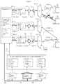
- FIG. 1shows a cellular tower embodiment of configurable broadband infrastructure including a remote software configurable wideband radiofrequency head and virtual antenna array system capable of being shared among multiple wireless carriers.
- FIG. 2shows more detail of the physical aspects of the configurable broadband infrastructure system capable of being shared among multiple wireless carriers.
- FIG. 3shows another example of the configurable broadband infrastructure system in operation.
- FIG. 4illustrates details of a manner in which the configurable broadband infrastructure system can simultaneously manage three of its various physical antennas according to the scheme previously discussed in FIG. 1 .
- FIG. 5shows an alternative embodiment of the configurable broadband infrastructure system.
- FIG. 6shows an alternative embodiment illustrating one manner in which selected physical antennas of the configurable broadband infrastructure system may be electrically combined to produce a larger virtual antenna.
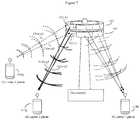
- FIG. 7shows an alternative version of a cellular tower configured with a stacked antenna array configuration in accordance with the present disclosure.
- FIG. 8illustrates exemplary details of information captured and displayed by a user interface of the configurable broadband infrastructure system.
- Embodiments of the disclosed the disclosed configurable broadband infrastructure systemmay include a combination remote wideband radiofrequency head system and digitally controlled reconfigurable virtual antenna array.
- a simplified overview of an embodiment of the disclosed system deployed at a cellular tower ( 100 )is shown in FIG. 1 .
- the systemmay include a plurality of physical wideband antennas, here shown in perspective as a circular eight antenna element array ( 102 ) (only three antenna elements A 1 , A 2 , and A 3 , each covering a roughly 45° angle, are depicted).
- a circular eight antenna element array102
- each of these physical wideband antennasare configured with their own, antenna specific, wideband converters ( 202 - c 1 , 202 - c 2 , 202 - c 3 and so on).
- wideband converterscan be high speed and wideband analog to digital (A/D) and digital to analog (D/A) converters, such as, for example, converters from the Texas Instruments TI ADC12Dxx00RF converter family or those available from Fujitsu Microelectronics America, Inc. converters, or other commercially available A/D and D/A converters.
- A/Danalog to digital
- D/Adigital to analog converters
- wideband analog to digital and digital to analog convertersconfigured to operate at GHz speeds in excess of 1 billion samples per second, may be used, with higher performance (greater A/D bits resolution and/or greater sampling rates) generally being preferable.
- the wideband convertersmay be other types of wideband converter devices, such I/Q modulators and demodulators, QAM modulators and demodulators, and the like.
- I/Q modulation and demodulation methodsallow digital data to be transformed to and from waveforms suitable for wireless transmission.
- modulationis represented in an I vs Q plane where the I axis corresponds to the in-phase component of a waveform, and Q represents the quadrature component of a waveform.
- I/Q modulators and demodulatorscan be digital devices that can accept digital I and Q input data and for example output or receive RF QAM waveforms as a result, and vice versa.
- the I/Q modulatorscan be analog devices, but work with I and Q data that has been converted to and from analog I and Q values using suitable analog to digital or digital to analog converters.
- I/Q modulators and demodulatorsas another type of wideband converter that can transform digital representation of RF waveforms from the digital domain of the system's processors, and the analog domain of the various RF wireless waveforms transmitted and received by the system's various antennas.
- Examples of digital I/Q modulatorsinclude, for example, those described by Bode et. al., U.S. Pat. No. 7,680,210, and Yoon, U.S Patent Publication 20060023811, the entire contents of both of which are incorporated herein by reference.
- Examples of analog I/Q modulatorswhich may interface with suitable wideband analog to digital converters, include the Linear Technology LTC55888-1 200 MHz to 6000 MHz Quadrature Modulator with Ultrahigh OIP3, and similar types of devices.
- These wideband converterswill be generally controlled by, and exchange data with, at least one system processor and memory.
- the system processor(s) and memorywill typically be configured to implement various software defined radio schemes such as, for example, the approaches disclosed by Harris, “ Digital Receivers and Transmitters Using Polyphase Filter Banks for Wireless Communications ”, IEEE transactions volume 51 (4), April 2003, pages 1395-1412.
- Other software defined radio methodsthat may be employed include those described by, for example, Tan et. al., U.S. Pat. No. 8,565,811; Ting et. al., U.S. Pat. No. 7,151,925; March et. al., U.S. Pat. No. 8,050,708; and Naik et. al., U.S. Pat.
- the processor(s)will often comprise various types of high performance digital signal processors and the like, as well as more standard general purpose processors (e.g. x86, ARM, MIPS other processor types) as needed.
- ASICsApplication specific integrated circuits
- other types of devices and methodsmay also be used for this type of work, and these can be viewed as being another type of processor.
- Software radio methodsare facilitated at least in part due to the availability of, for example, A/D converters capable of operating in a broadband mode and at very high (GHz range) speeds.
- A/D converterscapable of operating in a broadband mode and at very high (GHz range) speeds.
- the Texas Instruments TI ADC12Dxx00RF family of A/D converterscan sample with 12 bit resolution at frequencies of 2.7 GHz and greater, and at rates of 3.6 gigasamples per second (GSPS).
- GSPSgigasamples per second
- Fujitsu Microelectronics America, Inc.produces a 56 GSPS 8-bit A/D converter.
- Various types of wideband amplifiers and timersare also available to match this capability.
- the disclosed systemmay be characterized as configurable broadband infrastructure including a software defined combination remote wideband radiofrequency head system and a digitally controlled reconfigurable virtual (or physical) antenna array.
- virtualis used to denote the fact that the various users (e.g. wireless carriers) need not try to configure the various physical antennas directly. Rather, the system can present a more standard virtual antenna interface, that the wireless carriers can control, and the system can then handle the overhead of controlling the physical antennas accordingly.
- carriersmay be allowed to “write directly to hardware” and control the physical antennas directly.
- a virtual antenna systemcan help shield complexities and conflicts from the users. Additionally, a virtual antenna array system can help preserve confidential business information as well, so that a first carrier does not get too much insight into what a second carrier is doing.
- the various user (carrier) specified software defined radio schemeswill allow the user to define (via a software interface), the various user desired RF modulation/demodulation schemes, desired RF frequency ranges, power levels, and the like.
- the systemalso allows users, via the software interface and the system processors, to configure various virtual (or physical) antennas from the virtual antenna array (which in turn is based on an array of physical antennas).
- the systemcomprises at least one processor configured with a software interface that allows users (wireless carriers) to configure a number of virtual antennas, RF modulation/demodulation schemes, and RF frequency ranges to use for this virtual antenna array, thereby defining at least one “user virtual RF configuration”. That is the “user virtual RF configuration” will typically allow a user so specify at least a number of virtual antennas (here by specifying that user's particular desired virtual antenna array), RF modulation/demodulation schemes, and RF frequency ranges.
- FIGS. 2-8illustratively provide additional details regarding implementation of this scheme.
- the system's processor(s)use the various “user virtual RF configurations” to determine how to combine (typically by digital signal processing using the system processors) or split the analog to digital and digital to analog signals from the various wideband converters. These wideband converters are in turn (often via various amplifiers and frequency converters) connected to the system's various physical antennas.
- signals from two physical antennascan be digitally added by using the system processor to sum (literally adding by an addition type arithmetic operation) A/D digitized signals from the two physical antennas, thus forming a simple virtual antenna array (for receiving) composed of two physical antennas.
- a digital signal intended for transmissioncan be directed by the system processors to a first wideband converter coupled to a first physical antenna, as well as to a second wideband converter coupled to a second physical antenna.
- the output from the two converterscauses the two physical antennas to form a simple, two-antenna virtual antenna array.
- embodiments of the present systemmay enable wireless carriers to nearly instantly establish virtual infrastructure configurations which address their needs while simultaneously sharing physical components of the system.
- the present schemeallows the system to distribute wireless signals that have been received or transmitted using the system's various physical wideband antennas according the number of virtual antennas, RF modulation schemes, and RF frequency ranges defined by each user's (wireless carrier's) virtual RF configuration.
- the net resultis that the system ends up using its various processors and at least some of its various wideband converters to wirelessly receive or transmit packets or frames of digital data (usually to and from each user's customers) according to each user's virtual RF configuration.
- FIG. 1shows a diagram of configurable broadband infrastructure including a software defined combination remote wideband radiofrequency head and a digitally controlled reconfigurable virtual antenna array.
- the systemis configured on a tower (e.g. cellular tower 100 ) with a software reconfigurable virtual antenna array shown in perspective ( 102 ).
- This array ( 102 )is in turn composed of a plurality of physical broadband antennas ( 102 -A 1 , 102 -A 2 , 102 -A 3 ) that in a preferred embodiment are selected so that each physical broadband antenna operates over at least 1 GHz of frequency bandwidth.
- each individual physical antennais shown as having some directionality to it (here three of eight physical antennas, each with at least 45° of coverage are shown). This directionally makes for some good graphical examples, but is not a required feature of the invention.
- the various physical antennasare arranged in a circular array so as to provide, between them a full 360 degrees of wireless coverage. Note however that this is not intended to be limiting, and there can be situations where a full 360 degrees of wireless coverage is not necessary, or where no antenna directionality at all may be used.
- three different wireless carriers(users), a first 3G carrier 1 ( 110 ), a second 4G carrier 2 ( 112 ), and a third 5G carrier 3 ( 114 ) are each simultaneously using the same system to provide wireless cell phone coverage to their respective customers.
- the 3G carrier 1 ( 110 )is providing coverage to a 3G carrier 1 phone ( 110 p )
- the 4G carrier 2 ( 112 )is providing coverage to a 4G carrier 2 phone ( 112 p )
- the 5G carrier 3 ( 114 )is providing coverage to a 5G carrier 3 phone ( 114 p ).
- each carrierwill be serving multiple customers per tower.
- each carrieris using its own modulation scheme, frequency range, and potentially also its own power levels, and each carrier may also have its various wireless customers disposed in different locations relative to the tower ( 100 ).
- carrier 1 ( 110 )may have more customers located to the left (such as 110 p )
- carrier 2 ( 112 )may have more customers located in the middle (such as 112 p )
- carrier 3 ( 114 )may have more customers located to the right (such as 114 p ).
- each carriermay need to have more antennas allocated to different regions.
- each carrieruses the system's software interface ( 116 ) to configure the system according to that particular carrier's needs (see FIG. 8 for a more detailed discussion of this software interface).
- the carriersare each specifying their particular RF modulation scheme and virtual antenna type.
- the systemcan in turn analyze the choice of virtual antennas, and determine, for example, which converters tied to which physical antennas to use to achieve the desired result.
- 3G wireless carrier 1 ( 110 )is specifying a particular 3G CDMA modulation scheme, and antenna configuration favoring the direction of its customer ( 110 p ) via software interface ( 116 ) and commands ( 110 c ), then the system might automatically determine that physical antenna 102 -A 1 is best suited for this purpose, and use the converter ( 110 c ) to send and receive signals via antenna 102 -A 1 and RF waveforms ( 110 w ).
- 4G wireless carrier 2 ( 112 )is specifying its particular 4G OFDMA modulation scheme and antenna configuration favoring the direction of its customer ( 112 p ) via software interface ( 116 ) and commands ( 112 c ), then the system might determine that physical antenna 102 -A 1 is also best suited for this purpose, and use the converter ( 112 c ) to simultaneously send and receive signals via antenna 102 -A 1 and RF waveforms ( 112 w ). Wireless carrier 1 ( 110 ) and 2 ( 112 ) can otherwise proceed as if they had the system to themselves.
- 5G wireless carrier 3 ( 114 )is specifying its particular 5G modulation scheme and antenna configuration favoring the direction of its customer ( 114 p ) via software interface ( 116 ) and commands ( 114 c ), then the system might automatically determine that it should create a virtual antenna by combining physical antennas 102 -A 3 and 102 -A 3 , and possibly use phase adjust techniques (via RF waveforms 114 w - p 1 and 114 w - p 2 ) to provide better coverage.
- carrier 3 ( 114 )doesn't elect to “write to hardware”
- the systemcan keep track of these details automatically as well, and again carrier 3 simply interacts with a virtual antenna).
- FIG. 8shows a more detailed example one embodiment of the system software interface ( 116 ).
- the various users (carriers)can simply transmit to the system processor ( 130 ), one or more digital data packets or frames, formatted according to the system's software interface specifications, that contain that particular carrier's requested user virtual RF configuration and other desired RF properties.
- the various users (carriers)can send and receive information in digital format (e.g. send and receive data plane and control plane packets and frames, as well as send and receive virtual RF configurations various management plane packets and frames) from the tower ( 110 ) and the rest of the system using any suitable telecommunications data channel ( 120 a , 120 b ), including optical fiber, cable, or other type of wireless communication as desired.
- router-like terminologysuch as data plane, control plane, and management plane packets and frames
- the carrier's customer communications over the systemwill typically be handled by data plane and control plane packets and ( 120 a ) between the system and the various wireless carriers ( 110 , 112 , 114 ).
- the information that the carriers use to configure the systemcan be viewed as management plane data packets or frames ( 120 b ) between the various wireless carriers and the system.
- management plane data packets or frames120 Often, of course, all such communications between the various carriers (uses) and the system will generally travel over the same suitable telecommunications channel ( 120 in the other figures).
- ( 120 a ) and ( 120 b )generally refer to the same telecommunications channel(s) between the carriers and the system, here we will generally just refer to this channel(s) as ( 120 ).
- the various carrierscan then communicate with their various customers ( 110 p , 112 p , 114 p ) by transmitting and receiving various digital data packets or frames over communications channel ( 120 ).
- the systemcan then use stored information regarding the various RF modulation schemes and antenna configuration schemes, as well as the various user virtual RF configurations, to automatically (if desired) implement various software radio schemes and antenna sharing schemes in a manner that can be relatively transparent to the various carriers (users).
- QAM waveformssuch as QAM-64 as an example, which can digitally transmit 6 bits of data per QAM constellation. If the carriers had to transmit a full description of a QAM-64 waveform to the system by using a brute force, Nyquist-sampled, digitized version of the QAM-64 waveform, then a much large amount of data would need to be sent over channel ( 120 ) to the system. However, embodiments of the system require that only the underlying data transmitted by the RF waveforms needs to be specified and transmitted. Thus, neglecting overhead, only 6 bits of data need be sent over communications channel ( 120 ) in this case.
- the systemcan then take care some or all of the details of antenna configuration and modulating and demodulating the digital data according to that particular carrier's chosen scheme.
- the system's virtual antenna schemecan result in the same physical antenna handing communications for multiple different carriers and modulation schemes at the same time. This is possible because the system's processor(s) can first digitally compute multiple modulation schemes from multiple carriers, sum them (as one example), and then send the combined signals to the same antenna at the same time as needed.
- system(s) processorscan receive digitized signals from the same antennas containing multiple modulated waveforms from multiple carriers, use standard digital signal analysis methods to separate the various multiple waveforms, and then send the underlying information from the waveforms back to the various carriers.
- carriers ( 110 ) and ( 112 )are using two different RF modulation schemes (3G and 4G) and the same physical antenna ( 102 -A 1 ) to simultaneously communicate with their respective customers ( 110 p ) and ( 112 p ) using wireless waveforms 110 w and 112 w.
- carrier ( 114 )is using a different antenna scheme, in which it is using two physical antennas ( 102 -A 2 and 102 -A 3 ) as a single phase adjusted virtual antenna to communicate with its customer ( 114 p ) using a 5G modulation scheme with some phase adjustments between antennas ( 102 -A 2 ) and 102 (A 3 ) to produce wireless beams ( 114 w - p 1 ) and ( 114 w - p 2 ) with somewhat improved directionality.
- the systemmay automatically handle the overhead of determining what combination of various physical antenna directionality and various wireless waveform phase adjustments to use to produce good signal response, and minimize any conflicts between different carriers.
- the system and methodallow the various users (carriers) to configure a number of virtual antennas by using their respective user virtual RF configurations, and the system processor(s) to select which of the various physical antenna specific wideband converters to electronically (e.g. computationally) combine (or split) to form various types of virtual antennas.
- FIG. 2shows more detail of the physical aspects of the invention's software reconfigurable virtual antenna array.
- the circular antenna array ( 102 )previously shown in FIG. 1 in perspective and mounted on the tower ( 100 ), is now shown in a magnified top down view ( 200 ).
- the various physical antennas( 102 -A 1 , 102 -A 2 , 102 -A 3 . . . ) as previously discussed receive and transmit RF signals as a series of modulated waveforms.
- the various physical antennaswill be wideband antennas are configured for operation over at least 1 GHz of bandwidth. Additionally, in a preferred embodiment, these physical antennas will also be configured for operation over any base frequency between 600 MHz and 6 GHz. Alternatively multiple antenna types, each tuned for a narrower range of bandwidth or frequencies may be used. If less flexibility is desired, the bandwidth and/or frequency range of the various physical antennas may also be reduced.
- wireless waveformstransmit digital data
- the wireless waveformsthemselves can be best understood as being analog signals.
- the disclosed embodimentspermit wireless carriers to interact with the system by exchanging packets or frames of digital data.
- most or all of the computational overhead of the systemis also done digitally, for example using various types of digital signal processors ( 130 ).
- digital signal processors130
- the interface between the digital portion of the system ( 130 ) and the various analog type wireless waveforms received and transmitted by the various antennacan be exemplified by various types of wideband converters such as an array of wideband analog to digital (ADC) or digital to analog (DAC) converters. These are shown in FIG. 2 as converters ( 202 - c 1 ), ( 202 - c 2 ), ( 202 - c 3 ), and so on.
- each convertere.g. 202 - c 1
- each converteractually represents a converter set or dual function converter that can operate in both directions for both receiving and transmitting.
- the term “converter” hereis intended to indicate a bidirectional converter. However since this is cumbersome to draw; only single directional converters will be shown.
- each converter(converter set, bidirectional converter) is shown here connected to its own unique physical antenna. This is the most flexible arrangement as it allows the various system processors to create various types of virtual antennas by computational calculations that combine or separate signals from the different physical antennas via these converters. However as will be discussed, in some configurations the system processors can alternatively define some virtual antenna arrays by more direct electrical connections that may connect the same converters to multiple physical antennas.
- physical antenna 102 -A 1is connected to converter(s) 202 - c 1 , which in turn are connected to the system processors ( 130 ).
- the system processors ( 130 )are simultaneously handling the task of receiving wireless signals ( 110 w ) from carrier 1's customer ( 110 p ) and also transmitting wireless signals ( 112 w ) to carrier 2's customer ( 112 w ).
- STARsimultaneous transmit and receive
- various types of STAR (simultaneous transmit and receive) methodssuch as those described in Fenn, U.S. Pat. No. 8,749,441, the contents of which are incorporated herein by reference, or other STAR methods, such as the methods Cox et. al., “ Maximizing RF Spectrum Utilization with Simultaneous Transmit and Receive ” Microwave Journal, September 2014, Vol. 57 Issue 9, p 114-126 may optionally be used.
- each physical antennais reserved for only transmitting or only receiving.
- the transmit antenna and receive antennasmay be separate antennas oriented in the same direction, and also controlled by the system processors, such as shown in FIG. 7 .
- the system processors ( 130 )will typically be configured to attempt to minimize interference between the various carriers and RF modulation schemes, and/or to transmit warning messages to the carriers when some interference is unavoidable.
- carriersmay select various quality of service levels as to which carrier will automatically be given priority in such a situation.
- physical antenna 102 -A 1is simultaneously communicating with mobile phones ( 110 p ) and ( 112 p ) carried by customers of two different wireless carriers ( 110 ) and ( 112 ), each using a different frequency range and modulation scheme.
- the various different physical antennasalthough having some directionality, may also be configured so as to at least partially overlap with the directionality of other physical antennas, such as adjacent physical antennas.
- the systemis also configured to, either automatically, or alternatively under carrier control (such as through the software interface), adjust the relative phases of the waveforms emitted by the various antennas to further direct wireless energy towards desired locations.
- the systemhas automatically determined that the 5G carrier 3 phone ( 114 p ) is located in a location that is in between physical antenna 202 -A 2 and 202 -A 3 .
- the system processors(at least upon proper carrier authorization through the software interface) and converters ( 202 - c 2 and 202 - c 3 ) can automatically adjust the phases of the RF waveforms ( 114 w - p 1 and 114 w - p 2 ) emitted or received by antennas 202 -A 2 and 202 -A 3 so as to better direct the wireless beam(s) to the location of ( 114 p ).
- the software interface and the user virtual RF configurationcan be configured to allow users (or the system itself, automatically) to further configure a directionality of the various virtual antennas.
- Thisallows either the users or the system or both to define various types of directional virtual antennas. This can be done by either choosing physical antennas with suitable directionality, varying the phases of the wireless waveforms transmitted or received by the various antennas, or a combination of these two approaches.
- the system processor(s) and converterscan be configured to allow the various users (wireless carriers) to configure their desired RF modulation/demodulation schemes using the previously discussed I/Q methods and devices.
- the user virtual RF configurationcan be used to further define at least one I/Q RF modulation/demodulation scheme.
- at least some of the various wideband converters used to RF modulate or demodulate the packets or frames of digital data between RF waveforms and digital datamay also be I/Q RF modulators and demodulators.
- the system processormay allow the users (e.g. wireless carriers) to configure their various RF modulation/demodulation schemes by using at least some of the various I/Q type wideband converters to RF modulate or demodulate the frames of digital data between RF waveforms and digital data by using their user virtual RF configurations to further define at least one I/Q RF modulation/demodulation scheme.
- the userse.g. wireless carriers
- the system processormay allow the users (e.g. wireless carriers) to configure their various RF modulation/demodulation schemes by using at least some of the various I/Q type wideband converters to RF modulate or demodulate the frames of digital data between RF waveforms and digital data by using their user virtual RF configurations to further define at least one I/Q RF modulation/demodulation scheme.
- I/Q RF modulation and demodulation schemescan be advantageous because it can help reduce the computational demands on the system processor(s).
- the processorcan use the user virtual RF configurations to further configure the directionality of the various virtual antennas by adjusting the phases of the relevant wireless waveforms according to various I/Q RF modulation/demodulation schemes.
- phase adjustmentscan, of course, be done using other methods, including even digital signal processing based on brute force type Nyquist-sampling type methods, but of course schemes that result in lower processor loads and requirements are typically desirable.
- the systemcan adjust the directionality of the various virtual antennas by various methods.
- the systemcan adjust the relative phases of various (directional or non-directional) physical antennas by software selecting appropriate antennas, and using suitable digital signal processing techniques such as phase adjust techniques.
- the systemcan also control the directionality of the various physical antennas by selecting physical antennas with the desired direction, and combining or splitting them via direct electrical connections and suitable software controlled switches.
- FIG. 4shows more details of how the system can simultaneously manage three of its various physical antennas according to the schemes previously discussed in FIGS. 1-3 .
- the various carriers ( 110 , 112 , and 114 )use the software interface ( 116 ) to inform the system processor(s) ( 130 ) about the various carriers' preferences with regards to RF modulation/demodulation methods and antenna configuration.
- the system processor(s) ( 130 )can use their database of modulation and demodulation algorithms ( 400 ) and antenna configuration algorithms ( 402 ) and the input digital data packets or frames from the carriers (via 120 ), symbolized by digital signals ( 404 , 406 , and 408 ) to digitally convert the various transmitted digital data packets or frames ( 404 , 406 , 408 ) to digital RF output (e.g. digital RF waveforms in I/Q format, or digitized RF waveforms), as shown in ( 410 ).
- digital RF outputis being converted to analog RF signals using various broadband Digital to Analog Converters (DAC)) or else is doing the reverse operation using various broadband Analog to Digital Converters (ADC).
- DACDigital to Analog Converters
- ADCAnalog to Digital Converters
- other types of converterssuch as I/Q converters, may also be used.
- the system processor ( 130 )can automatically use information previously obtained on the location of the various mobile phones ( 110 p , 112 p , and 114 p ), its database of modulation and demodulation algorithms ( 400 ), its database of antenna configuration algorithms ( 402 ), and various digital converters (such as 202 - c 1 , 202 - c 2 , 202 - c 3 ) to simultaneously modulate the RF waveforms for the 3G carrier 1 phone ( 110 p ) and 4G carrier 2 phone ( 112 p ) in accordance with 3G and 4G modulation protocols, respectively.
- various digital converterssuch as 202 - c 1 , 202 - c 2 , 202 - c 3
- the systemcan then use the previously discussed Digital to Analog converters or other type of converters to simultaneously transmit both waveforms using physical antenna ( 102 -A 1 ).
- the systemcan also use its antenna configuration algorithms ( 402 ) to adjust the phases of the input or output RF signals over antennas ( 102 -A 2 ) and ( 102 -A 3 ) so as to steer the beam directions ( 114 w - p 1 and 114 w - p 2 ) towards the desired destination, which in this case is the location of 5G carrier 5 phone ( 114 p ).
- the process of antenna selection and managementmay be done automatically by the system, or alternatively relevant information and parameters may be passed to the various carriers over the software interface ( 116 ), and the various carriers may play a more active role in antenna management as desired.
- the system processor(s)may allow the various users (wireless carriers) to configure which RF frequency range(s) they want to use by, for example, also allowing the carriers (users) to select, via the user virtual RF configuration, the various conversion frequencies of these RF frequency up/down converters. This allows the system processor(s), for example, to compute the various waveforms at a lower frequency (generally computationally less intensive), and then upconvert (or down convert) to and from higher frequencies by suitably configured RF frequency up and down converters.
- the database of modulation and demodulation algorithms ( 400 ) that encodes for various RF modulation/demodulation and signal encoding/decoding schemescan include any schemes or standards including, for example, GSM, IS-95, TDMA, FDMA, OFDM, CDMA, WCDMA, OTFS and QAM.
- At least some of the wideband converterscan be configured to RF modulate or demodulate the frames of digital data between RF waveforms and digital data by using the user (wireless carrier's) virtual RF configuration to further define at least one I/Q RF modulation/demodulation scheme.
- this at least one I/Q RF modulation/demodulation schemecan include any known RF modulation/demodulation and signal encoding/decoding scheme.
- FIG. 5shows an alternative embodiment of a configurable broadband infrastructure system in accordance with the disclosure. Except as otherwise provided below, the embodiment of FIG. 5 may operate similarly to the embodiment of FIG. 4 .
- the process of transforming the digital data frames ( 404 ), ( 406 ), ( 408 ) to and from RF waveformsis done using wideband digital/RF converters including several different devices.
- the processor(s) ( 130 )can use a database of modulation and demodulation algorithms ( 400 ) to convert the data to and from an I/Q modulation type coordinate system, and this digital IQ data in turn can be provided to, or received from, a digital I/Q modulator or demodulator device ( 500 , 502 , 504 ).
- this processwill produce a base RF signal modulated according to carrier choice, which also carries the data from and to the various digital data frames.
- This base RF signalcan in turn be sent to RF frequency up converters (or down converters) ( 510 , 512 , 514 ) that in turn transpose the RF signal to and from the desired frequency range.
- This RF input or outputin turn can be sent (or received from to an RF amplifier ( 520 , 522 , 524 ) and the amplified RF signal can then be sent to the appropriate antenna(s).
- the processessentially operates in reverse to receive RF signals from the various remote wireless devices (e.g. various customer mobile phones). These RF signals are again represented by ( 110 w ), ( 112 w ), ( 114 w - p 1 ), and ( 114 w - p 2 ). Note that each physical antenna may be connected to multiple frequency converters and amplifiers, and even multiple converters, as desired, in order to accommodate the differing needs of multiple users (carriers).
- virtual antenna arraysmay also be created by various types of processor ( 130 ) and software ( 402 ) controlled electronic switches that directly electrically connect, or disconnect, various physical antennas from each other.
- the software interface and the user virtual RF configurationcan be such as to allow the system to, for example, further electronically combine or connect (typically by software controlled switches) or by direct electrical connection a plurality of physical antennas to create one or more virtual antennas with desired properties.
- the directionality of the virtual antennas(thereby defining directional virtual antennas) may be configured by using software controlled switches to directly electrically combine or connect physical antennas with the desired directional properties.
- Other virtual antenna characteristicssuch as sensitivity, bandwidth, frequency range, and the like can also be created by appropriate combination of various physical antennas according to a software controlled, direct electrical connection, type switching scheme.
- the various physical wideband antennascan be directional physical wideband antennas.
- the system processor(s)can, for example, allow the users (wireless carriers) to configure the directionality of various virtual antennas by using the virtual RF configuration to select and directly electrically combine suitable physical antennas.
- this direct electrical combinationis done according to the directionality of said directional physical wideband antennas, but again other characteristics, such as antenna bandwidth, frequency range, gain, etc. can also be used.
- user virtual RF configurationas input to the system via the system software interface, can allow the system users to further configure the RF characteristics of the virtual antennas, thereby defining customized virtual antennas.
- the physical wideband antennasmay have different antenna characteristics or properties (e.g. different directionality, sensitivity/gain, bandwidth, frequency range, polarization, and the like).
- This antenna configurationwill typically be done computationally (e.g. using digital signal processing methods) by the system processor(s), but can also be aided, as needed, by the processor directed formation (usually using software controlled switches such as ( 600 , and 602 ) of direct electronic connections between the various physical antennas as needed.
- FIG. 6which is largely based on FIG. 5 , shows an alternative embodiment showing how the system can electronically, and under processor control, switch, combine or gang select two different physical antennas ( 102 -A 2 ) and ( 102 -A 3 ) to produce a larger virtual antenna by direct electrical connections.
- various physical antennasmay be electrically directly connected to form a larger virtual antenna using commands from processor ( 130 ) and software ( 402 ) controlled switches ( 600 , 602 ).
- carrier 3 ( 114 )can use the software interface to request that the system engage switch ( 602 ) to electrically connect physical antennas ( 102 -A 2 ) and ( 102 -A 3 ) to create a larger virtual antenna that covers (in this example) a wider range of angles.
- engaging software controlled switch ( 602 )causes antennas ( 102 -A 2 ) and ( 102 -A 3 ) to become effectively electrically connected.
- Thisrenders the two wideband digital/RF converters comprised of digital I/Q modulator or demodulator device ( 502 , 504 ) and frequency RF frequency up converter (or down converter) ( 512 , 514 ) mutually redundant, since only one such digital/RF converter (i.e., first converter 502 / 512 or second converter 504 / 514 ) is needed to handle both physical antennas.
- both antennasemit (or detect) RF waveforms ( 114 w ) at the same phase.
- FIG. 6suggests that although different wireless carriers may use the software interface to electrically combine physical antennas, it may further be useful to allow the system processor to also have at least some control over which antenna combinations are allowed, since the requirements of different carriers may conflict.
- the system processormay also have at least some control over which antenna combinations are allowed, since the requirements of different carriers may conflict.
- allowing carriers to cause such direct electrical connection of physical antennasmay be useful.
- Such conflictscould be potentially resolved by according different wireless carriers different quality of service levels, where the preferences of wireless carriers with higher quality of service levels would be given priority over those having lower quality of service levels.
- FIG. 7shows an alternative embodiment with an alternative antenna arrangement.
- the various antennasmay also be configured in a stacked arrangement, with multiple physical broadband antennas (exemplified by multiple physical antennas in a first circular array 102 and multiple physical antennas in a second circular array 702 ) are generally configured to point in the same direction.
- multiple physical antennas ( 102 )may be used to receive wireless RF signals, while multiple physical antennas ( 702 ) may be used to transmit wireless RF signals, thus reducing cross-talk between the transmitting and receiving antennas.
- this stacked antenna arrangementmay be used to allow the system to phase adjust the signals received or transmitted by the stacked antennas to better adjust the elevation (e.g. angle relative to the horizon) of the wireless RF beams.
- wireless devices close to the base of the towercan be better distinguished over wireless devices further away from the base of the tower because the elevation of the wireless beams will be different.
- the signals from the stacked antennascan be electrically (rather than computationally) combined as well, as per the example previously shown in FIG. 6 .
- the software interface between the configurable broadband infrastructure system and the wireless carrierscan be as simple as a scheme in which the processor(s) ( 130 ) implement a management plane type convention by which the various wireless carriers can use their computerized control devices to send and receive (typically via connection 120 ) digital packets or frames (e.g. management plane packets or frames) of information to manage the system.
- the “software interface”can be as little as giving the system processor(s) ( 130 ) an ability to parse digital packets or frames (e.g. management plane packets or frames), received from the various users (wireless carriers) and to use the results of this parsing operation to configure the system accordingly.
- the “software interface”can also be used by the system processor(s) to transmit management plane information to the various wireless carriers (carried again by various packets or frames) acknowledging previous commands, informing about the status of the system, and the like.
- the software interfacemay include a human readable graphical user interface, such as that presented by a Web page, configured to allow human users having devices equipped with suitable Web browsers to configure the system.
- the system's processor(s) ( 130 )are configured to present a software interface to the various users (wireless carriers) that allows these carriers to each configure, on a user (carrier) specific basis, various types of user (carrier) specific number of virtual antennas, RF modulation/demodulation schemes, and RF frequency ranges—as before, each such scheme may be termed a user or carrier specific virtual RF configuration.
- the system's processor(s) ( 130 )can then use these various user or carrier specific virtual RF configurations to determine how to combine (again usually mathematically in the processor, but occasionally also by directly electrically connecting various antennas via software controlled electrical switches) the various analog to digital and digital to analog signals from the various wideband converters.
- the system processor(s)can also use the various user (carrier) specific virtual RF configurations to determine, according to the number of virtual antennas, RF modulation schemes, and RF frequency ranges defined by the various user specific virtual RF configurations, as to how the system should distribute wireless signals received or transmitted using the various physical wideband antennas.
- the system processorcan then use at least some of the wideband converters to wirelessly receive or transmit, on a user (carrier) specific basis, frames of digital data according to each user's (carrier's) specific virtual RF configuration.
- FIG. 8shows more details of how, in some embodiments, the software interface ( 116 ) can operate.
- the 3G carrier 1 ( 110 ), and 4G carrier 2 ( 112 )wish to control the system at a more detailed level (such “writing to hardware”).
- the carriersspecify the RF wireless modulation scheme (e.g. 3G, 4G, 5G), as well as the RF frequency, wireless transmitter power, and also antenna elevation angle.
- the system antennasare configured in a stacked arrangement as previously shown in FIG. 7 , and also that the locations of the 3G wireless device 1 ( 110 p ) and 4G wireless device 2 ( 112 p ) are also as previously shown in FIG. 7 .
- carrier 1can transmit configuration information to the software interface ( 116 ) specifying (in digital form) ( 820 ) that carrier 1 wishes configure the system to communicate with devices such as device 1 using (i) a 3G CDMA modulation scheme at the 850 MHz frequency, (ii) 10 Watts of transmitter power, and (iii) antennas 102 -A 1 and 702 -A 1 configured (though suitable phase adjustment) to tilt the wireless beam down at a 5 degree angle.
- a 3G CDMA modulation schemeat the 850 MHz frequency
- 10 Watts of transmitter power
- antennas 102 -A 1 and 702 -A 1configured (though suitable phase adjustment) to tilt the wireless beam down at a 5 degree angle.
- carrier 1's user specific virtual RF configurationcan be transmitted with a management plane type configuration packet or frame such as “00011000001010101010100001100101”, and the system's processor(s) ( 130 ) can parse this configuration packet or frame and set the system accordingly.
- carrier 2can transmit configuration information to the software interface ( 116 ) specifying (in digital form) ( 830 ) that carrier 2 wishes to configure the system to communicate to devices such as device 2 using (i) a 4G OFDMA modulation scheme at 750 MHz using (ii) 2 Watts of power, and (iii) the same antennas 102 -A 1 and 702 -A 1 configured (through suitable phase adjustment) to tit the wireless beam down at a 10 degree angle.
- carrier 2's user specific virtual RF configurationcan be transmitted with a management plane type configuration packet or frame such as “0010000001001011001001010”, and the system's processors ( 130 ) can again parse this configuration packet or frame and set the system accordingly.
- carriersmay transmit various types of standing orders to the system specifying standard antenna configurations that the carrier authorizes the system to use under different scenarios.
- the systemmay also offer different degrees of service, under which in the event of conflict between carrier needs (e.g. carriers wish to operate the system simultaneously in a configuration that favors one carrier at the expense of another), some carriers preferences (i.e. the carrier's preferred antenna configuration) may be prioritized over the preferences of other carriers.
- a method of operating a combination remote wideband radiofrequency head and digitally controlled reconfigurable virtual antenna arrayincludes configuring a plurality of physical wideband antennas to be electrically connected to a corresponding plurality of wideband converters.
- Each wideband convertermay include a wideband analog to digital and digital to analog converter and be controlled by, and exchange data with, at least one processor and memory.
- the methodfurther includes using the at least one processor to provide a software interface to enable configuration of a number of virtual antennas, RF modulation/demodulation and/or encoding schemes, and RF frequency ranges, thereby defining at least one user virtual RF configuration.
- the processormay combine signals from the wideband converters and distribute wireless signals received or transmitted using the plurality of physical wideband antennas in accordance with the at least one user virtual RF configuration.
- the at least one processormay cooperate with one or more of the wideband converters to wirelessly receive or transmit packets or frames of digital data according to the at least one user virtual RF configuration.
- the methodmay include allowing users to configure, via the software interface, a number of virtual antennas by using the user virtual RF configuration to select which of the physical wideband converters to electronically combine to form the virtual antennas.
- the at least one user virtual RF configurationmay also specify RF modulation/demodulation schemes pursuant to which ones of the wideband converters perform RF modulation or demodulation operations.
- the combination remote wideband radiofrequency head and digitally controlled reconfigurable virtual antenna arrayfurther include a plurality of RF frequency up/down converters connected between the physical antennas and the physical antenna specific wideband converters.
- the user virtual RF configurationmay specify the conversion frequencies utilized by the plurality of RF frequency up/down converters.
- At least some of the wideband convertersmay be configured to RF modulate or demodulate the packets or frames of digital data between RF waveforms and digital data in accordance with the user virtual RF configuration where such configuration may further define at least one I/Q RF modulation/demodulation scheme.
- the user virtual RF configurationmay specify RF characteristics of the virtual antennas, thereby defining customized virtual antennas.
- at least some of the physical wideband antennasmay have different characteristics.
- the user virtual RF configurationmay configure the characteristics of customized virtual antennas by selecting which of the physical antenna specific wideband converters are used to electronically combine ones of the physical wideband antennas of differing antenna characteristics.
- the software interfacemay further be used to define the user virtual RF configuration so as to specify a directionality of the virtual antennas, thereby defining directional virtual antennas.
- This directionalitymay be effected by, for example, adjusting phases of at least one I/Q RF modulation/demodulation scheme implemented by the antenna specific wideband converters connected to ones of the physical antennas.
- the physical wideband antennasare configured for operation over at least 1 GHz of bandwidth and/or over any base frequency between 600 MHz and 6 GHz.
- the methodcontemplates enabling, via the software interface, a plurality of users (e.g., wireless carriers) to each configure, on a user specific basis, a user specific number of virtual antennas, RF modulation/demodulation schemes, and RF frequency ranges, thereby defining a plurality of user specific virtual RF configurations.
- the at least one processoruses the plurality of user specific virtual RF configurations in connection with combining and/or distributing wireless signals received or transmitted using the plurality of physical wideband antennas according to the number of virtual antennas, RF modulation schemes, and RF frequency ranges defined by said plurality of user specific virtual RF configurations.
- the methodmay further include using the at least one processor and at least some of the wideband converters to wirelessly receive or transmit, on a user specific basis, packets or frames of digital data according to each user's specific virtual RF configuration.
- the disclosureis directed to a combination remote wideband radiofrequency head and reconfigurable virtual antenna array system.
- the systemincludes a plurality of physical wideband antennas.
- Each of the plurality of physical wideband antennasmay be configured with physical antenna specific wideband converters including wideband analog to digital and digital to analog converters.
- the wideband convertersmay be controlled by at least one processor configured to execute instructions stored within a memory.
- the processormay define a software interface allowing users to configure a number of virtual antennas, RF modulation/demodulation schemes, and RF frequency ranges, thereby defining at least one user virtual RF configuration.
- the virtual antennasmay be configured by, for example, establishing electrical connections between the plurality of physical wideband antennas or by otherwise combining signal received from, or by distributing signals to, combinations of the plurality of physical wideband antennas.
- the at least one processormay be further configured to use at least some of the wideband converters to wirelessly receive or transmit packets or frames of digital data according to the at least one user virtual RF configuration.
- the various methods or processes outlined hereinmay be coded as software that is executable on one or more processors that employ any one of a variety of operating systems or platforms. Additionally, such software may be written using any of a number of suitable programming languages and/or programming or scripting tools, and also may be compiled as executable machine language code or intermediate code that is executed on a framework or virtual machine.
- Examples of computer codeinclude, but are not limited to, micro-code or micro-instructions, machine instructions, such as produced by a compiler, code used to produce a web service, and files containing higher-level instructions that are executed by a computer using an interpreter.
- embodimentsmay be implemented using imperative programming languages (e.g., C, Fortran, etc.), functional programming languages (Haskell, Erlang, etc.), logical programming languages (e.g., Prolog), object-oriented programming languages (e.g., Java, C++, etc.) or other suitable programming languages and/or development tools.
- Additional examples of computer codeinclude, but are not limited to, control signals, encrypted code, and compressed code.
- inventive conceptsmay be embodied as a computer readable storage medium (or multiple computer readable storage media) (e.g., a computer memory, one or more floppy discs, compact discs, optical discs, magnetic tapes, flash memories, circuit configurations in Field Programmable Gate Arrays or other semiconductor devices, or other non-transitory medium or tangible computer storage medium) encoded with one or more programs that, when executed on one or more computers or other processors, perform methods that implement the various embodiments of the invention discussed above.
- the computer readable medium or mediacan be transportable, such that the program or programs stored thereon can be loaded into one or more different computers or other processors to implement various aspects of the present invention as discussed above.
- programor “software” are used herein in a generic sense to refer to any type of computer code or set of computer-executable instructions that can be employed to program a computer or other processor to implement various aspects of embodiments as discussed above. Additionally, it should be appreciated that according to one aspect, one or more computer programs that when executed perform methods of the present invention need not reside on a single computer or processor, but may be distributed in a modular fashion amongst a number of different computers or processors to implement various aspects of the present invention.
- Computer-executable instructionsmay be in many forms, such as program modules, executed by one or more computers or other devices.
- program modulesinclude routines, programs, objects, components, data structures, etc. that perform particular tasks or implement particular abstract data types.
- functionality of the program modulesmay be combined or distributed as desired in various embodiments.
- data structuresmay be stored in computer-readable media in any suitable form.
- data structuresmay be shown to have fields that are related through location in the data structure. Such relationships may likewise be achieved by assigning storage for the fields with locations in a computer-readable medium that convey relationship between the fields.
- any suitable mechanismmay be used to establish a relationship between information in fields of a data structure, including through the use of pointers, tags or other mechanisms that establish relationship between data elements.
- inventive conceptsmay be embodied as one or more methods, of which an example has been provided.
- the acts performed as part of the methodmay be ordered in any suitable way. Accordingly, embodiments may be constructed in which acts are performed in an order different than illustrated, which may include performing some acts simultaneously, even though shown as sequential acts in illustrative embodiments.
- the phrase “at least one,” in reference to a list of one or more elements,should be understood to mean at least one element selected from any one or more of the elements in the list of elements, but not necessarily including at least one of each and every element specifically listed within the list of elements and not excluding any combinations of elements in the list of elements.
- This definitionalso allows that elements may optionally be present other than the elements specifically identified within the list of elements to which the phrase “at least one” refers, whether related or unrelated to those elements specifically identified.
- “at least one of A and B”can refer, in one embodiment, to at least one, optionally including more than one, A, with no B present (and optionally including elements other than B); in another embodiment, to at least one, optionally including more than one, B, with no A present (and optionally including elements other than A); in yet another embodiment, to at least one, optionally including more than one, A, and at least one, optionally including more than one, B (and optionally including other elements); etc.
Landscapes
- Engineering & Computer Science (AREA)
- Computer Networks & Wireless Communication (AREA)
- Signal Processing (AREA)
- Mobile Radio Communication Systems (AREA)
Abstract
Description
Claims (23)
Priority Applications (1)
| Application Number | Priority Date | Filing Date | Title |
|---|---|---|---|
| US15/187,671US10574317B2 (en) | 2015-06-18 | 2016-06-20 | System and method for providing wireless communication services using configurable broadband infrastructure shared among multiple network operators |
Applications Claiming Priority (2)
| Application Number | Priority Date | Filing Date | Title |
|---|---|---|---|
| US201562181691P | 2015-06-18 | 2015-06-18 | |
| US15/187,671US10574317B2 (en) | 2015-06-18 | 2016-06-20 | System and method for providing wireless communication services using configurable broadband infrastructure shared among multiple network operators |
Publications (2)
| Publication Number | Publication Date |
|---|---|
| US20170019297A1 US20170019297A1 (en) | 2017-01-19 |
| US10574317B2true US10574317B2 (en) | 2020-02-25 |
Family
ID=57776016
Family Applications (1)
| Application Number | Title | Priority Date | Filing Date |
|---|---|---|---|
| US15/187,671Active2036-10-12US10574317B2 (en) | 2015-06-18 | 2016-06-20 | System and method for providing wireless communication services using configurable broadband infrastructure shared among multiple network operators |
Country Status (1)
| Country | Link |
|---|---|
| US (1) | US10574317B2 (en) |
Cited By (3)
| Publication number | Priority date | Publication date | Assignee | Title |
|---|---|---|---|---|
| US11258506B2 (en)* | 2017-11-28 | 2022-02-22 | Apple Inc. | Method and apparatus for transmitting and receiving multiple carriers with multiple antennas |
| US11831391B2 (en) | 2018-08-01 | 2023-11-28 | Cohere Technologies, Inc. | Airborne RF-head system |
| US12224838B2 (en) | 2020-12-18 | 2025-02-11 | British Telecommunications Public Limited Company | Method of controlling a radio access point |
Families Citing this family (73)
| Publication number | Priority date | Publication date | Assignee | Title |
|---|---|---|---|---|
| US9130638B2 (en) | 2011-05-26 | 2015-09-08 | Cohere Technologies, Inc. | Modulation and equalization in an orthonormal time-frequency shifting communications system |
| US10667148B1 (en) | 2010-05-28 | 2020-05-26 | Cohere Technologies, Inc. | Methods of operating and implementing wireless communications systems |
| US10681568B1 (en) | 2010-05-28 | 2020-06-09 | Cohere Technologies, Inc. | Methods of data channel characterization and uses thereof |
| US9071285B2 (en) | 2011-05-26 | 2015-06-30 | Cohere Technologies, Inc. | Modulation and equalization in an orthonormal time-frequency shifting communications system |
| US9071286B2 (en) | 2011-05-26 | 2015-06-30 | Cohere Technologies, Inc. | Modulation and equalization in an orthonormal time-frequency shifting communications system |
| US11943089B2 (en) | 2010-05-28 | 2024-03-26 | Cohere Technologies, Inc. | Modulation and equalization in an orthonormal time-shifting communications system |
| US9444514B2 (en) | 2010-05-28 | 2016-09-13 | Cohere Technologies, Inc. | OTFS methods of data channel characterization and uses thereof |
| US8976851B2 (en) | 2011-05-26 | 2015-03-10 | Cohere Technologies, Inc. | Modulation and equalization in an orthonormal time-frequency shifting communications system |
| US9031141B2 (en) | 2011-05-26 | 2015-05-12 | Cohere Technologies, Inc. | Modulation and equalization in an orthonormal time-frequency shifting communications system |
| US9912507B2 (en) | 2012-06-25 | 2018-03-06 | Cohere Technologies, Inc. | Orthogonal time frequency space communication system compatible with OFDM |
| US10469215B2 (en) | 2012-06-25 | 2019-11-05 | Cohere Technologies, Inc. | Orthogonal time frequency space modulation system for the Internet of Things |
| US10090972B2 (en) | 2012-06-25 | 2018-10-02 | Cohere Technologies, Inc. | System and method for two-dimensional equalization in an orthogonal time frequency space communication system |
| US10003487B2 (en) | 2013-03-15 | 2018-06-19 | Cohere Technologies, Inc. | Symplectic orthogonal time frequency space modulation system |
| US10411843B2 (en) | 2012-06-25 | 2019-09-10 | Cohere Technologies, Inc. | Orthogonal time frequency space communication system compatible with OFDM |
| US9967758B2 (en) | 2012-06-25 | 2018-05-08 | Cohere Technologies, Inc. | Multiple access in an orthogonal time frequency space communication system |
| US9929783B2 (en)* | 2012-06-25 | 2018-03-27 | Cohere Technologies, Inc. | Orthogonal time frequency space modulation system |
| US10090973B2 (en) | 2015-05-11 | 2018-10-02 | Cohere Technologies, Inc. | Multiple access in an orthogonal time frequency space communication system |
| EP3295572A4 (en) | 2015-05-11 | 2018-12-26 | Cohere Technologies, Inc. | Systems and methods for symplectic orthogonal time frequency shifting modulation and transmission of data |
| US9866363B2 (en) | 2015-06-18 | 2018-01-09 | Cohere Technologies, Inc. | System and method for coordinated management of network access points |
| CN112532558B (en) | 2015-06-27 | 2024-12-10 | 凝聚技术股份有限公司 | Orthogonal time-frequency space communication system compatible with OFDM |
| US10892547B2 (en) | 2015-07-07 | 2021-01-12 | Cohere Technologies, Inc. | Inconspicuous multi-directional antenna system configured for multiple polarization modes |
| US10693581B2 (en) | 2015-07-12 | 2020-06-23 | Cohere Technologies, Inc. | Orthogonal time frequency space modulation over a plurality of narrow band subcarriers |
| EP3348015B1 (en) | 2015-09-07 | 2022-09-07 | Cohere Technologies, Inc. | Multiple access using orthogonal time frequency space modulation |
| WO2017087706A1 (en) | 2015-11-18 | 2017-05-26 | Cohere Technologies | Orthogonal time frequency space modulation techniques |
| CN108781072B (en) | 2015-12-09 | 2022-04-26 | 凝聚技术公司 | Pilot encapsulation using complex orthogonal functions |
| US10666314B2 (en) | 2016-02-25 | 2020-05-26 | Cohere Technologies, Inc. | Reference signal packing for wireless communications |
| EP3433969B1 (en) | 2016-03-23 | 2021-11-03 | Cohere Technologies, Inc. | Receiver-side processing of orthogonal time frequency space modulated signals |
| WO2017173160A1 (en) | 2016-03-31 | 2017-10-05 | Cohere Technologies | Channel acquisition using orthogonal time frequency space modulated pilot signal |
| US9667307B1 (en) | 2016-03-31 | 2017-05-30 | Cohere Technologies | Wireless telecommunications system for high-mobility applications |
| EP3437197B1 (en) | 2016-04-01 | 2022-03-09 | Cohere Technologies, Inc. | Tomlinson-harashima precoding in an otfs communication system |
| WO2017173389A1 (en) | 2016-04-01 | 2017-10-05 | Cohere Technologies | Iterative two dimensional equalization of orthogonal time frequency space modulated signals |
| WO2017201467A1 (en) | 2016-05-20 | 2017-11-23 | Cohere Technologies | Iterative channel estimation and equalization with superimposed reference signals |
| EP3497785B1 (en) | 2016-08-12 | 2024-03-13 | Cohere Technologies, Inc. | Method for multi-user multiplexing of orthogonal time frequency space signals |
| EP3497907A4 (en) | 2016-08-12 | 2020-03-04 | Cohere Technologies, Inc. | LOCALIZED EQUALIZATION FOR CHANNELS WITH INTERMEDIATE INTERFERENCE INTERFERENCES |
| EP3497799A4 (en) | 2016-08-12 | 2020-04-15 | Cohere Technologies, Inc. | ITERATIVE MULTI-STAGE EQUALIZATION AND DECODING |
| US11310000B2 (en) | 2016-09-29 | 2022-04-19 | Cohere Technologies, Inc. | Transport block segmentation for multi-level codes |
| EP3520310B1 (en) | 2016-09-30 | 2021-10-27 | Cohere Technologies, Inc. | Uplink user resource allocation for orthogonal time frequency space modulation |
| EP3549200B1 (en) | 2016-12-05 | 2022-06-29 | Cohere Technologies, Inc. | Fixed wireless access using orthogonal time frequency space modulation |
| EP3566379B1 (en) | 2017-01-09 | 2024-12-11 | Cohere Technologies, Inc. | Pilot scrambling for channel estimation |
| US10356632B2 (en) | 2017-01-27 | 2019-07-16 | Cohere Technologies, Inc. | Variable beamwidth multiband antenna |
| US10568143B2 (en) | 2017-03-28 | 2020-02-18 | Cohere Technologies, Inc. | Windowed sequence for random access method and apparatus |
| EP3610582A4 (en) | 2017-04-11 | 2021-01-06 | Cohere Technologies, Inc. | Digital communication using dispersed orthogonal time frequency space modulated signals |
| EP4109983A1 (en) | 2017-04-21 | 2022-12-28 | Cohere Technologies, Inc. | Communication techniques using quasi-static properties of wireless channels |
| EP3616265A4 (en) | 2017-04-24 | 2021-01-13 | Cohere Technologies, Inc. | Multibeam antenna designs and operation |
| WO2018200577A1 (en) | 2017-04-24 | 2018-11-01 | Cohere Technologies | Digital communication using lattice division multiplexing |
| US10749580B2 (en)* | 2017-05-12 | 2020-08-18 | Telefonaktiebolaget Lm Ericsson (Publ) | Virtualized massive MIMO in multi-operator wireless networks |
| EP3652907A4 (en) | 2017-07-12 | 2021-04-07 | Cohere Technologies, Inc. | DATA MODULATION SCHEMES BASED ON ZAK TRANSFORMATION |
| US11546068B2 (en) | 2017-08-11 | 2023-01-03 | Cohere Technologies, Inc. | Ray tracing technique for wireless channel measurements |
| WO2019036492A1 (en) | 2017-08-14 | 2019-02-21 | Cohere Technologies | Transmission resource allocation by splitting physical resource blocks |
| EP3679493B1 (en) | 2017-09-06 | 2024-03-13 | Cohere Technologies, Inc. | Lattice reduction in orthogonal time frequency space modulation |
| US11283561B2 (en) | 2017-09-11 | 2022-03-22 | Cohere Technologies, Inc. | Wireless local area networks using orthogonal time frequency space modulation |
| US11190308B2 (en) | 2017-09-15 | 2021-11-30 | Cohere Technologies, Inc. | Achieving synchronization in an orthogonal time frequency space signal receiver |
| US11532891B2 (en) | 2017-09-20 | 2022-12-20 | Cohere Technologies, Inc. | Low cost electromagnetic feed network |
| WO2019068053A1 (en) | 2017-09-29 | 2019-04-04 | Cohere Technologies, Inc. | Forward error correction using non-binary low density parity check codes |
| EP4362344A3 (en) | 2017-11-01 | 2024-07-31 | Cohere Technologies, Inc. | Precoding in wireless systems using orthogonal time frequency space multiplexing |
| WO2019113046A1 (en) | 2017-12-04 | 2019-06-13 | Cohere Technologies, Inc. | Implementation of orthogonal time frequency space modulation for wireless communications |
| WO2019157230A1 (en) | 2018-02-08 | 2019-08-15 | Cohere Technologies, Inc. | Aspects of channel estimation for orthogonal time frequency space modulation for wireless communications |
| US11489559B2 (en) | 2018-03-08 | 2022-11-01 | Cohere Technologies, Inc. | Scheduling multi-user MIMO transmissions in fixed wireless access systems |
| WO2019241589A1 (en) | 2018-06-13 | 2019-12-19 | Cohere Technologies, Inc. | Reciprocal calibration for channel estimation based on second-order statistics |
| EP3954055A1 (en)* | 2019-04-12 | 2022-02-16 | Telefonaktiebolaget LM Ericsson (publ) | Online mimo wireless network virtualization with unknown channel information |
| US10461421B1 (en)* | 2019-05-07 | 2019-10-29 | Bao Tran | Cellular system |
| US10498029B1 (en) | 2019-07-15 | 2019-12-03 | Bao Tran | Cellular system |
| US11321282B2 (en) | 2019-05-17 | 2022-05-03 | Bao Tran | Blockchain cellular system |
| US12047476B2 (en)* | 2019-07-10 | 2024-07-23 | The Adt Security Corporation | Cellular converter apparatus and method |
| US10694399B1 (en)* | 2019-09-02 | 2020-06-23 | Bao Tran | Cellular system |
| US10812992B1 (en) | 2019-09-02 | 2020-10-20 | Bao Tran | Cellular system |
| EP4104296A1 (en) | 2020-02-14 | 2022-12-21 | Telefonaktiebolaget LM Ericsson (publ) | Online convex optimization with periodic updates for downlink multi-cell mimo wireless network virtualization |
| US20230284154A1 (en)* | 2020-08-14 | 2023-09-07 | Telefonaktiebolaget Lm Ericsson (Publ) | Delay-tolerant constrained online convex optimization |
| EP4331193A4 (en) | 2021-04-29 | 2024-10-30 | Cohere Technologies, Inc. | ULTRA WIDEBAND SIGNALS WITH ORTHOGONAL TIME-FREQUENCY SPACE MODULATION |
| US12185134B1 (en) | 2023-12-20 | 2024-12-31 | Khue Duong | Wireless system |
| US12141675B1 (en) | 2024-03-17 | 2024-11-12 | Bao Tran | Wireless system |
| US12132267B1 (en) | 2024-03-17 | 2024-10-29 | Bao Tran | Wireless system |
| US12143941B1 (en) | 2024-03-17 | 2024-11-12 | Khue Duong | Wireless system |
Citations (192)
| Publication number | Priority date | Publication date | Assignee | Title |
|---|---|---|---|---|
| US4754493A (en) | 1977-05-25 | 1988-06-28 | Emi Limited | Automatic recognition and guidance arrangements |
| US5083135A (en) | 1990-11-13 | 1992-01-21 | General Motors Corporation | Transparent film antenna for a vehicle window |
| US5182642A (en) | 1991-04-19 | 1993-01-26 | General Dynamics Lands Systems Inc. | Apparatus and method for the compression and transmission of multiformat data |
| US5623511A (en) | 1994-08-30 | 1997-04-22 | Lucent Technologies Inc. | Spread spectrum code pulse position modulated receiver having delay spread compensation |
| US5831977A (en) | 1996-09-04 | 1998-11-03 | Ericsson Inc. | Subtractive CDMA system with simultaneous subtraction in code space and direction-of-arrival space |
| US5872542A (en) | 1998-02-13 | 1999-02-16 | Federal Data Corporation | Optically transparent microstrip patch and slot antennas |
| US5956624A (en) | 1994-07-12 | 1999-09-21 | Usa Digital Radio Partners Lp | Method and system for simultaneously broadcasting and receiving digital and analog signals |
| US6212246B1 (en) | 1996-11-21 | 2001-04-03 | Dsp Group, Inc. | Symbol-quality evaluation in a digital communications receiver |
| US6289063B1 (en) | 1998-09-02 | 2001-09-11 | Nortel Networks Limited | QAM receiver with improved immunity to crosstalk noise |
| US20010031022A1 (en) | 1996-10-11 | 2001-10-18 | Paul Petrus | Method for reference signal generation in the presence of frequency offsets in a communications station with spatial processing |
| US20010033614A1 (en) | 2000-01-20 | 2001-10-25 | Hudson John E. | Equaliser for digital communications systems and method of equalisation |
| US20010046205A1 (en) | 1994-09-30 | 2001-11-29 | Easton Kenneth D. | Multipath search processor for a spread spectrum multiple access communication system |
| US20020001308A1 (en) | 2000-05-26 | 2002-01-03 | Alcatel | Method of transmitting synchronous transport modules via a synchronous transport network |
| US6356555B1 (en) | 1995-08-25 | 2002-03-12 | Terayon Communications Systems, Inc. | Apparatus and method for digital data transmission using orthogonal codes |
| US20020034191A1 (en) | 1998-02-12 | 2002-03-21 | Shattil Steve J. | Method and apparatus for transmitting and receiving signals having a carrier interferometry architecture |
| US6388621B1 (en) | 2000-06-20 | 2002-05-14 | Harris Corporation | Optically transparent phase array antenna |
| US6426983B1 (en) | 1998-09-14 | 2002-07-30 | Terayon Communication Systems, Inc. | Method and apparatus of using a bank of filters for excision of narrow band interference signal from CDMA signal |
| CN1376338A (en) | 1999-09-21 | 2002-10-23 | 美商内数位科技公司 | Variable Expansion Factor Multi-User Detector |
| US20020181388A1 (en) | 2001-05-07 | 2002-12-05 | Jain Vijay K. | Communication system using orthogonal wavelet division multiplexing (OWDM) and OWDM-spread spectrum (OWSS) signaling |
| US20020181390A1 (en) | 2001-04-24 | 2002-12-05 | Mody Apurva N. | Estimating channel parameters in multi-input, multi-output (MIMO) systems |
| US20020181607A1 (en) | 1998-06-15 | 2002-12-05 | Sony International (Europe) Gmbh | Transmitter and method to cancel interference in OFDM communication |
| WO2003028400A1 (en) | 2001-09-27 | 2003-04-03 | Qualcomm Incorporated | Handoff method and apparatus with dual pilots in a communication system |
| US20030073464A1 (en) | 2001-05-25 | 2003-04-17 | Giannakis Georgios B. | Space-time coded transmissions within a wireless communication network |
| US6608864B1 (en) | 1999-05-26 | 2003-08-19 | 3Com Corporation | Method and apparatus for fault recovery in a decision feedback equalizer |
| US20030185295A1 (en) | 2001-09-18 | 2003-10-02 | Yousef Nabil R. | Fast computation of coefficients for a variable delay decision feedback equalizer |
| US6654429B1 (en) | 1998-12-31 | 2003-11-25 | At&T Corp. | Pilot-aided channel estimation for OFDM in wireless systems |
| US20030235147A1 (en) | 2002-06-24 | 2003-12-25 | Walton Jay R. | Diversity transmission modes for MIMO OFDM communication systems |
| US20040044715A1 (en) | 2002-06-18 | 2004-03-04 | Akram Aldroubi | System and methods of nonuniform data sampling and data reconstruction in shift invariant and wavelet spaces |
| US6704366B1 (en) | 1999-06-08 | 2004-03-09 | Sagem Sa | Time and frequency interleaving system for transmitting digital data between fixed or mobile stations |
| US20040086027A1 (en) | 2002-10-31 | 2004-05-06 | Shattil Steve J. | Orthogonal superposition coding for direct-sequence communications |
| EP1432168A1 (en) | 2002-12-16 | 2004-06-23 | Urmet Sistemi S.p.a. | Multicarrier CDMA transmission method using Hadamard time-frequency spreading codes, and a transmitter and a receiver for said method |
| US20040131011A1 (en) | 2002-09-26 | 2004-07-08 | Kabushiki Kaisha Toshiba | Transmission signals, method and apparatus |
| US20040174812A1 (en) | 2001-08-10 | 2004-09-09 | Yutaka Murakami | Transmission device, reception device and radio communication method |
| US20040189581A1 (en) | 2003-03-28 | 2004-09-30 | Kawasaki Microelectronics, Inc. | Multiline addressing drive method and apparatus for passive matrix liquid crystal, and a liquid crystal panel |
| US20040218523A1 (en) | 2003-05-01 | 2004-11-04 | Prabodh Varshney | Method and apparatus for increasing data rates in a wideband MC-CDMA telecommunication system |
| CN1579077A (en) | 2002-08-15 | 2005-02-09 | 株式会社东芝 | Channel tracking and signal detection in mimo systems |
| US20050136943A1 (en) | 2003-10-07 | 2005-06-23 | Banerjee Debarag N. | Location-assisted wireless communication |
| US20050157820A1 (en) | 2004-01-15 | 2005-07-21 | Supat Wongwirawat | Digital receiver having adaptive carrier recovery circuit |
| US20050157778A1 (en) | 2004-01-15 | 2005-07-21 | Trachewsky Jason A. | Orthogonal normalization for a radio frequency integrated circuit |
| US20050180517A1 (en) | 2004-02-16 | 2005-08-18 | Pioneer Corporation | Digital broadcast signal receiving apparatus and method |
| US20050207334A1 (en) | 2000-01-28 | 2005-09-22 | Zion Hadad | OFDM communication channel |
| US6956814B1 (en) | 2000-02-29 | 2005-10-18 | Worldspace Corporation | Method and apparatus for mobile platform reception and synchronization in direct digital satellite broadcast system |
| US20050251844A1 (en) | 2001-02-02 | 2005-11-10 | Massimiliano Martone | Blind correlation for high precision ranging of coded OFDM signals |
| US20060008021A1 (en) | 2004-06-30 | 2006-01-12 | Nokia Corporation | Reduction of self-interference for a high symbol rate non-orthogonal matrix modulation |
| US20060039270A1 (en) | 2004-06-28 | 2006-02-23 | Thomas Strohmer | Method for pulse shape design for OFDM |
| US7010048B1 (en) | 1998-02-12 | 2006-03-07 | Aqvity, Llc | Multiple access method and system |
| WO2006132589A2 (en) | 2005-06-09 | 2006-12-14 | Telefonaktiebolaget Lm Ericsson (Publ) | Time and frequency channel estimation in an ofdm system |
| WO2007004297A1 (en) | 2005-07-06 | 2007-01-11 | Matsushita Electric Industrial Co., Ltd. | Transmitter and transmission method |
| US20070014272A1 (en) | 2005-06-16 | 2007-01-18 | Ravi Palanki | Pilot and data transmission in a quasi-orthogonal single-carrier frequency division multiple access system |
| US20070038691A1 (en) | 2005-04-07 | 2007-02-15 | Emmanuel Candes | Methods for performing fast discrete curvelet transforms of data |
| US20070078661A1 (en) | 2005-09-30 | 2007-04-05 | Portalplayer, Inc. | Configurable system for performing repetitive actions and method for configuring and operating same |
| US20070104283A1 (en) | 2005-10-31 | 2007-05-10 | Jin-Kyu Han | Apparatus and method for transmitting/receiving data in a multi-antenna communication system |
| US20070110131A1 (en) | 2005-11-15 | 2007-05-17 | Tommy Guess | Iterative interference cancellation using mixed feedback weights and stabilizing step sizes |
| CN1972272A (en) | 2005-09-08 | 2007-05-30 | 瑞昱半导体股份有限公司 | Elimination Method of Internal Symbol Interference and Carrier Interference in Multi-carrier Modulation Receiver |
| US20070211952A1 (en) | 2000-12-01 | 2007-09-13 | Lizardtech, Inc. | Method of generating matrix factors for a finite-dimensional linear transform |
| US20070211814A1 (en) | 2004-12-09 | 2007-09-13 | Qualcomm Incorporated | Data transmission with spatial spreading in a mimo communication system |
| US20070237181A1 (en) | 2004-07-29 | 2007-10-11 | Woungsik Cho | Method and System for Generating Switching Timing Signal for Separating Transmitting and Receiving Signal in Optical Repeater of Mobile Telecommunication Network Using Tdd and Ofdm Modulation |
| US20070253504A1 (en) | 2006-04-28 | 2007-11-01 | Fujitsu Limited | MIMO-OFDM transmitter |
| US20070253465A1 (en) | 2006-04-27 | 2007-11-01 | Tarik Muharemovic | Methods and apparatus to allocate reference signals in wireless communication systems |
| US7327812B2 (en) | 2003-03-27 | 2008-02-05 | Docomo Communications Laboratories Europe Gmbh | Apparatus and method for estimating a plurality of channels |
| US20080043857A1 (en) | 2003-08-28 | 2008-02-21 | Alexandre Ribeiro Dias | Ofdm Channel Estimation and Tracking for Multiple Transmit Antennas |
| US20080117999A1 (en) | 2006-11-10 | 2008-05-22 | Qualcomm Incorporated | Providing antenna diversity in a wireless communication system |
| US7392018B1 (en) | 2006-06-13 | 2008-06-24 | Saraband Wireless, Inc. | Channel estimation applique for wireless communications |
| US20080187062A1 (en) | 2007-02-06 | 2008-08-07 | Interdigital Technology Corporation | Method and apparatus for multiple-input multiple- output feedback generation |
| US20080186843A1 (en) | 2005-03-30 | 2008-08-07 | Jianglei Ma | Method and System For Combining Ofdm and Transformed Ofdm |
| US20080232504A1 (en) | 2005-08-23 | 2008-09-25 | Jianglei Ma | Methods and Systems For Ofdm Multiple Zone Partitioning |
| US20080273624A1 (en) | 2007-05-03 | 2008-11-06 | Mark Kent | Method and system for cqi/pmi feedback for precoded mimo systems utilizing differential codebooks |
| US20080310485A1 (en) | 2007-06-15 | 2008-12-18 | Qualcomm Incorporated | System and methods for controlling modem hardware |
| US20080310383A1 (en) | 2007-06-15 | 2008-12-18 | Sharp Laboratories Of America, Inc. | Systems and methods for designing a sequence for code modulation of data and channel estimation |
| US20090080403A1 (en) | 2005-03-03 | 2009-03-26 | Stmicroelectronics Ltd | Wireless lan data rate adaptation |
| US20090092259A1 (en) | 2006-05-17 | 2009-04-09 | Creative Technology Ltd | Phase-Amplitude 3-D Stereo Encoder and Decoder |
| US20090103593A1 (en) | 2007-10-17 | 2009-04-23 | Marcos Antonio Bergamo | Array Antenna System and Spread Spectrum Beamformer Method |
| US20090122854A1 (en) | 2007-11-14 | 2009-05-14 | The Hong Kong University Of Science And Technology | Frequency domain equalization with transmit precoding for high speed data transmission |
| US20090161804A1 (en) | 2007-12-21 | 2009-06-25 | Qualcomm Incorporated | Receiver window shaping in OFDM to mitigate narrowband interference |
| US20090204627A1 (en) | 2008-02-11 | 2009-08-13 | Nir Asher Sochen | Finite harmonic oscillator |
| US20090222226A1 (en) | 2005-10-25 | 2009-09-03 | Baraniuk Richard G | Method and Apparatus for On-Line Compressed Sensing |
| US20090303961A1 (en) | 2007-01-05 | 2009-12-10 | Branislav Popovic | Method, transceiver and telecommunication system for generating reference sequence matrices and for mapping elements thereof |
| US20100001901A1 (en) | 2006-04-12 | 2010-01-07 | Baraniuk Richard G | Apparatus and Method for Compressive Sensing Radar Imaging |
| US20100008432A1 (en) | 2008-07-08 | 2010-01-14 | Qualcomm Incorporated | Methods and systems for reducing papr of an ofdm signal |
| US20100027608A1 (en) | 2006-09-29 | 2010-02-04 | Paolo Priotti | Scrambled multicarrier transmission |
| US20100040154A1 (en) | 2008-08-15 | 2010-02-18 | Infineon Technologies Ag | Channel estimation |
| US20100073232A1 (en) | 2008-09-22 | 2010-03-25 | Soji Sajuyigbe | Wide Angle Impedance Matching Using Metamaterials in a Phased Array Antenna System |
| US7689049B2 (en) | 2006-08-31 | 2010-03-30 | Donald Martin Monro | Matching pursuits coding of data |
| US20100111138A1 (en) | 2004-04-06 | 2010-05-06 | Texas Instruments Incorporated | Versatile System for Dual Carrier Transformation in Orthogonal Frequency Division Multiplexing |
| US20100142476A1 (en) | 2008-03-20 | 2010-06-10 | Zte Corporation | Method for mapping downlink dedicated pilots to resource elements in extended cyclic prefix frame structure |
| US20100187914A1 (en) | 2009-01-26 | 2010-07-29 | Geneva Cleantech Inc. | Methods and apparatus for power factor correction and reduction of distortion in and noise in a power supply delivery network |
| US7773685B2 (en) | 2002-05-27 | 2010-08-10 | Nokia Corporation | Transmitting and receiving methods |
| US20100203841A1 (en) | 2009-02-06 | 2010-08-12 | Qualcomm Incorporated | Methods and systems for fourier-quadratic basis channel estimation in ofdma systems |
| US20100208676A1 (en) | 2007-09-27 | 2010-08-19 | Beijing Xinwei Telecom Technology Inc. | Signal Transmission Method and Apparatus for OFDMA Wireless Communication System |
| US20100238787A1 (en) | 2006-09-11 | 2010-09-23 | Jiann-Ching Guey | Detection of time-frequency hopping patterns |
| US20100277308A1 (en) | 2009-04-30 | 2010-11-04 | Miodrag Potkonjak | Measurement-based wireless device system level management |
| US20100303136A1 (en) | 2009-05-29 | 2010-12-02 | Ashikhmin Alexei E | Channel Estimation in a Multi-Channel Communication System Using Pilot Signals Having Quasi-Orthogonal Subpilots |
| US20100322349A1 (en) | 2006-10-23 | 2010-12-23 | Moon Il Lee | Method for transmitting data using cyclic delay diversity |
| US7864877B2 (en) | 2005-09-28 | 2011-01-04 | Nokia Corporation | Data transmission in communication system by disabling radiation patterns |
| US7864836B1 (en) | 2007-10-31 | 2011-01-04 | Samsung Electronics Co., Ltd. | Adaptive orthogonal frequency division multiplexing (OFDM) equalizers, OFDM receivers including the same, and methods thereof |
| US20110007789A1 (en) | 2002-07-18 | 2011-01-13 | Garmany Jan D | Detection of Low-Amplitude Echoes in a Received Communication Signal |
| US20110110532A1 (en) | 2009-11-06 | 2011-05-12 | Motorola, Inc. | Howling suppression using echo cancellation |
| US20110116489A1 (en) | 2009-11-13 | 2011-05-19 | Interdigital Patent Holdings, Inc. | Method and apparatus for providing vht frequency reuse for wlans |
| US20110116516A1 (en) | 2006-04-24 | 2011-05-19 | Electronics And Telecommunications Research Institute | Method of generating pilot pattern for adaptive channel estimation in ofdma systems, method of transmitting/receiving using the pilot pattern and apparatus thereof |
| US20110126071A1 (en) | 2008-08-11 | 2011-05-26 | Seung Hee Han | Method and apparatus of transmitting information in wireless communication system |
| US20110131463A1 (en) | 2009-12-02 | 2011-06-02 | Lsi Corporation | Forward substitution for error-correction encoding and the like |
| JP2011127910A (en) | 2009-12-15 | 2011-06-30 | Hitachi Automotive Systems Ltd | Radar apparatus and radar system |
| WO2011105704A2 (en) | 2010-02-26 | 2011-09-01 | 엘지전자 주식회사 | Method for transceiving a signal, and base station and user equipment for same |
| US20110216808A1 (en) | 2001-10-17 | 2011-09-08 | Nortel Networks Limited | Scattered pilot pattern and channel estimation method for mimo-ofdm systems |
| EP2375604A1 (en) | 2009-01-07 | 2011-10-12 | Panasonic Corporation | Wireless communication apparatus, wireless communication system and wireless communication method |
| WO2011137699A1 (en) | 2010-05-06 | 2011-11-10 | Panasonic Corporation | Orthogonal codes based code division multiplexing method, multiplexing device, and de-multiplexing device |
| US20110286498A1 (en) | 2009-11-24 | 2011-11-24 | Qualcomm Incorporated | Apparatus and method for channel estimation using compressive sensing |
| US20110286502A1 (en) | 2008-09-12 | 2011-11-24 | Panasonic Corporation | Wireless transmitter and precoding method |
| US20110287778A1 (en) | 2010-05-24 | 2011-11-24 | Moshe Levin | Method and system for estimation of mobile station velocity in a cellular system based on geographical data |
| US20110289391A1 (en) | 2008-12-23 | 2011-11-24 | Fraunhofer-Gesellschaft Zur Foerderung Der Angewandten Forschung E.V. | Interleaver device and receiver for a signal generated by the interleaver device |
| US20110292971A1 (en) | 2010-05-28 | 2011-12-01 | Ronny Hadani | Communications method employing orthonormal time-frequency shifting and spectral shaping |
| US20110299379A1 (en) | 2009-01-19 | 2011-12-08 | Stefania Sesia | Process for Beamforming Data to be Transmitted by a Base Station in a MU-MIMO System and Apparatus for Performing the Same |
| US20110305267A1 (en) | 2008-08-20 | 2011-12-15 | Rius I Riu Jaume | Precoder for a Communication System and Methods Used in Said Communication System |
| US20120021769A1 (en) | 2009-03-27 | 2012-01-26 | Bengt Lindoff | Methods and Arrangements for Enabling Estimation of a Position of a Mobile Terminal |
| US20120045995A1 (en) | 2009-04-27 | 2012-02-23 | Hiroshi Nakano | Interference suppression wireless communication system and interference suppression wireless communication device |
| US8155658B1 (en) | 2008-10-21 | 2012-04-10 | Clearwire Ip Holdings Llc | Methods and systems for providing dynamic bandwidth adaptation in wireless systems |
| US20120120970A1 (en) | 2010-11-15 | 2012-05-17 | National Chiao Tung University | System And Method For Processing A Frequency Division Multiplexing Signal |
| US20120140716A1 (en) | 2010-12-03 | 2012-06-07 | Telefonaktiebolaget L M Ericsson (Publ) | Method and Arrangement for Transmitting Uplink Control |
| US20120170684A1 (en) | 2010-12-30 | 2012-07-05 | Raymond Yim | Method and System for Decoding OFDM Signals Subject to Narrowband Interference |
| US20120170531A1 (en) | 2011-01-04 | 2012-07-05 | Nec Laboratories America, Inc. | Resource allocation in 4g mimo cellular uplinks |
| US8229017B1 (en) | 2007-12-13 | 2012-07-24 | Marvell International Ltd. | Transmit beamforming utilizing channel estimation matrix decomposition feedback in a wireless MIMO communication system |
| US20120201322A1 (en) | 2010-05-28 | 2012-08-09 | Shlomo Selim Rakib | Signal modulation method resistant to echo reflections and frequency offsets |
| US20120213098A1 (en) | 2011-02-21 | 2012-08-23 | Future Wireless Tech LLC | Real-time and synchronization Internet of things analyzer System Architecture |
| US8259845B2 (en) | 2007-05-25 | 2012-09-04 | Telefonaktiebolaget L M Ericsson (Publ) | Method and apparatus for communicating with root-nyquist, self-transform pulse shapes |
| US20120235795A1 (en) | 2009-11-30 | 2012-09-20 | Westvalley Digital Technologies, Inc. | Active rfid tag, application system and method thereof |
| US20120269201A1 (en) | 2008-10-09 | 2012-10-25 | Sony Corporation | Frame and data pattern structure for multi-carrier systems |
| US20120272117A1 (en) | 2009-11-17 | 2012-10-25 | Sony Corporation | Transmitter and receiver for broadcasting data and providing incremental redundancy |
| US20120306685A1 (en) | 2010-01-27 | 2012-12-06 | Toyota Jidosha Kabushiki Kaisha | Radar system and direction detecting method |
| US20120320994A1 (en) | 2010-02-26 | 2012-12-20 | Sony Corporation | Encoder and encoding method providing incremental redundancy |
| US20130003789A1 (en) | 2011-06-29 | 2013-01-03 | Industrial Cooperation Foundation, KOREA NATIONAL UNIVERSITY OF TRANSPORTATION | Wireless communication method and apparatus using adaptive transmission polarization control |
| US20130021977A1 (en) | 2010-03-29 | 2013-01-24 | Murata Manufacturing Co., Ltd. | Method and apparatus for integer frequency offset estimation in wireless communication system |
| US20130058390A1 (en) | 2010-02-23 | 2013-03-07 | The University Court Of The University Of Edinburg | Enhanced spatial modulation |
| US8401131B2 (en) | 2007-12-11 | 2013-03-19 | Eads Secure Networks | Reduction of interference in an OFDM signal with weighting vectors evolving in vector subspaces |
| US20130077579A1 (en) | 2011-09-25 | 2013-03-28 | Heejeong Cho | Method for allocating resources in broadband wireless access system |
| US20130083661A1 (en) | 2011-10-03 | 2013-04-04 | Vivek Gupta | Multi-RAT Carrier Aggregation for Integrated WWAN-WLAN Operation |
| US20130121497A1 (en) | 2009-11-20 | 2013-05-16 | Paris Smaragdis | System and Method for Acoustic Echo Cancellation Using Spectral Decomposition |
| US20130128932A1 (en) | 2011-11-23 | 2013-05-23 | Industrial Technology Research Institute | Channel parameter estimation method |
| US20130230010A1 (en) | 2010-11-09 | 2013-09-05 | Lg Electronics Inc. | Method and Terminal Apparatus for Transmitting a Power Status Report in a Wireless Communication System |
| US20130260787A1 (en) | 2012-03-30 | 2013-10-03 | Fujitsu Limited | Apparatus and method for detecting a location of a mobile station in a mobile communication system |
| WO2013148546A1 (en) | 2012-03-26 | 2013-10-03 | Shlomo Selim Rakib | Signal modulation method resistant to echo reflections and frequency offsets |
| US20130279627A1 (en) | 2008-05-06 | 2013-10-24 | Industrial Technology Research Institute | System and Method for Pilot Design |
| US20130315133A1 (en) | 2012-05-11 | 2013-11-28 | Kabushiki Kaisha Toshiba | Wireless communications apparatus, a method and a communication system for performing relay selection |
| US8619892B2 (en) | 2009-01-22 | 2013-12-31 | Kabushiki Kaisha Toshiba | Wireless communication method and apparatus |
| WO2014004585A1 (en) | 2012-06-25 | 2014-01-03 | Ronny Hadani | Modulation and equalization in an orthonormal time-frequency shifting communications system |
| US20140010171A1 (en)* | 2012-07-05 | 2014-01-09 | Centurylink Intellectual Property Llc | Multi-Service Provider Wireless Access Point |
| US8717210B2 (en) | 2010-04-27 | 2014-05-06 | Technion Research & Development Foundation Ltd. | Multi-channel sampling of pulse streams at the rate of innovation |
| US20140143639A1 (en) | 2011-05-09 | 2014-05-22 | Sony Corporation | Encoder and encoding method providing incremental redundancy |
| US20140161154A1 (en) | 2011-05-26 | 2014-06-12 | Cohere Technologies, Inc. | Modulation and equalization in an orthonormal time-frequency shifting communications system |
| US20140169406A1 (en) | 2011-05-26 | 2014-06-19 | Cohere Technologies, Inc. | Modulation and equalization in an orthonormal time-frequency shifting communications system |
| US20140169433A1 (en) | 2011-05-26 | 2014-06-19 | Cohere Technologies, Inc. | Modulation and equalization in an orthonormal time-frequency shifting communications system |
| US20140169441A1 (en) | 2011-05-26 | 2014-06-19 | Cohere Technologies, Inc. | Modulation and equalization in an orthonormal time-frequency shifting communications system |
| US20140169385A1 (en) | 2011-05-26 | 2014-06-19 | Cohere Technologies, Inc. | Modulation and equalization in an orthonormal time-frequency shifting communications system |
| US20140169437A1 (en) | 2011-05-26 | 2014-06-19 | Cohere Technologies, Inc. | Modulation and equalization in an orthonormal time-frequency shifting communications system |
| US20140169436A1 (en) | 2011-05-26 | 2014-06-19 | Cohere Technologies, Inc. | Modulation and equalization in an orthonormal time-frequency shifting communications system |
| US20140177751A1 (en) | 2011-08-05 | 2014-06-26 | Sharp Kabushiki Kaisha | Precoding apparatus, program for precoding, and integrated circuit |
| JP2014150469A (en) | 2013-02-04 | 2014-08-21 | Mitsubishi Electric Corp | Equalization device and equalization method |
| US20140247803A1 (en) | 2013-03-04 | 2014-09-04 | Bernard Arambepola | Block-Based Time-Frequency Interleaving and De-Interleaving |
| US8892048B1 (en) | 2010-12-01 | 2014-11-18 | Netblazr Inc. | Transparent multi-element antenna |
| US20140348252A1 (en) | 2011-12-23 | 2014-11-27 | Orange | Method for transmitting at least one multi-carrier signal consisting of ofdm-oqam symbols |
| US20140364128A1 (en) | 2013-06-05 | 2014-12-11 | Samsung Electronics Co., Ltd. | Method and apparatus for handover in communication system |
| US20150043525A1 (en) | 2012-04-27 | 2015-02-12 | Huawei Technologies Co., Ltd. | User pairing method, device and system for realizing user scheduling |
| US8983511B2 (en) | 2010-02-26 | 2015-03-17 | Lg Electronics Inc. | Method for transceiving a signal, and base station and user equipment for same |
| US20150117395A1 (en) | 2010-05-28 | 2015-04-30 | Cohere Technologies, Inc. | Otfs methods of data channel characterization and uses thereof |
| US20150327085A1 (en) | 2010-05-28 | 2015-11-12 | Cohere Technologies, Inc. | Otfs methods of data channel characterization and uses thereof |
| US20150382231A1 (en) | 2014-06-25 | 2015-12-31 | General Electric Company | Dynamic adjustment of a wireless network media access control parameter |
| WO2016014598A1 (en) | 2014-07-21 | 2016-01-28 | Cohere Technologies, Inc. | Otfs methods of data channel characterization and uses thereof |
| US20160135132A1 (en) | 2014-11-07 | 2016-05-12 | Parallel Wireless, Inc. | Self-Calibrating and Self-Adjusting Network |
| US20160164587A1 (en)* | 2013-08-09 | 2016-06-09 | Huawei Technologies Co., Ltd. | Method and System for Sharing Antenna between Multiple Operators and Radio Frequency and Digital Conversion Unit |
| US20160254889A1 (en) | 2002-05-14 | 2016-09-01 | Genghiscomm Holdings, LLC | Spreading and Precoding in OFDM |
| US20160277225A1 (en) | 2013-11-27 | 2016-09-22 | Telefonaktiebolaget Lm Ericsson (Publ) | Sending And Detecting Synchronization Signals And An Associated Information Message |
| US20160309345A1 (en) | 2013-12-17 | 2016-10-20 | Adaptive Spectrum And Signal Alignment, Inc. | Systems methods and apparatuses for implementing distributed wireless data sharing and control systems |
| WO2016176642A1 (en) | 2015-04-30 | 2016-11-03 | Cohere Technologies, Inc. | Orthogonal time frequency space modulation system for the internet of things |
| WO2016183240A1 (en) | 2015-05-11 | 2016-11-17 | Cohere Technologies, Inc. | Orthogonal time frequency space modulation system |
| WO2016183230A1 (en) | 2015-05-11 | 2016-11-17 | Cohere Technologies | Systems and methods for symplectic orthogonal time frequency shifting modulation and transmission of data |
| WO2016209848A1 (en) | 2015-06-22 | 2016-12-29 | Cohere Technologies, Inc. | Symplectic orthogonal time frequency space modulation system |
| US20160380743A1 (en) | 2015-06-18 | 2016-12-29 | Cohere Technologies, Inc. | System and method for coordinated management of network access points |
| US9537575B2 (en) | 2014-08-08 | 2017-01-03 | Nxgen Partners Ip, Llc | Modulation and multiple access technique using orbital angular momentum |
| WO2017003952A1 (en) | 2015-06-27 | 2017-01-05 | Cohere Technologies, Inc. | Orthogonal time frequency space communication system compatible with ofdm |
| US20170012810A1 (en) | 2012-06-25 | 2017-01-12 | Cohere Technologies, Inc. | Orthogonal time frequency space modulation system |
| US20170012749A1 (en) | 2012-06-25 | 2017-01-12 | Cohere Technologies, Inc. | Orthogonal time frequency space communication system compatible with ofdm |
| WO2017011478A1 (en) | 2015-07-12 | 2017-01-19 | Cohere Technologies, Inc. | Orthogonal time frequency space communication system compatible with ofdm |
| US9553984B2 (en) | 2003-08-01 | 2017-01-24 | University Of Florida Research Foundation, Inc. | Systems and methods for remotely tuning hearing devices |
| US20170033899A1 (en) | 2012-06-25 | 2017-02-02 | Cohere Technologies, Inc. | Orthogonal time frequency space modulation system for the internet of things |
| US20170040711A1 (en) | 2015-07-07 | 2017-02-09 | Cohere Technologies, Inc. | Inconspicuous multi-directional antenna system configured for multiple polarization modes |
| US20170078054A1 (en) | 2015-05-11 | 2017-03-16 | Cohere Technologies, Inc. | Multiple access in an orthogonal time frequency space communication system |
| US20170099607A1 (en) | 2012-06-25 | 2017-04-06 | Cohere Technologies, Inc. | Multiple access in an orthogonal time frequency space communication system |
| US20170099122A1 (en) | 2012-06-25 | 2017-04-06 | Cohere Technologies, Inc. | System and method for two-dimensional equalization in an orthogonal time frequency space communication system |
| US20170117994A1 (en) | 2014-08-08 | 2017-04-27 | Nxgen Partners Ip, Llc | Modulation and multiple access technique using orbital angular momentum |
| US20170149595A1 (en) | 2012-06-25 | 2017-05-25 | Cohere Technologies, Inc. | Orthogonal time frequency space communication system compatible with ofdm |
| US20170149594A1 (en) | 2013-03-15 | 2017-05-25 | Cohere Technologies, Inc. | Symplectic orthogonal time frequency space modulation system |
| US20170288710A1 (en) | 2016-04-01 | 2017-10-05 | Cohere Technologies, Inc. | Tomlinson-harashima precoding in an otfs communication system |
| EP3378187A1 (en) | 2015-11-18 | 2018-09-26 | Cohere Technologies, Inc. | Orthogonal time frequency space modulation techniques |
Family Cites Families (1)
| Publication number | Priority date | Publication date | Assignee | Title |
|---|---|---|---|---|
| US20140001071A1 (en)* | 2012-06-29 | 2014-01-02 | Michael David Sanders | Package for laundry detergent having apparent pre-treat capability |
- 2016
- 2016-06-20USUS15/187,671patent/US10574317B2/enactiveActive
Patent Citations (246)
| Publication number | Priority date | Publication date | Assignee | Title |
|---|---|---|---|---|
| US4754493A (en) | 1977-05-25 | 1988-06-28 | Emi Limited | Automatic recognition and guidance arrangements |
| US5083135A (en) | 1990-11-13 | 1992-01-21 | General Motors Corporation | Transparent film antenna for a vehicle window |
| US5182642A (en) | 1991-04-19 | 1993-01-26 | General Dynamics Lands Systems Inc. | Apparatus and method for the compression and transmission of multiformat data |
| US5956624A (en) | 1994-07-12 | 1999-09-21 | Usa Digital Radio Partners Lp | Method and system for simultaneously broadcasting and receiving digital and analog signals |
| US5623511A (en) | 1994-08-30 | 1997-04-22 | Lucent Technologies Inc. | Spread spectrum code pulse position modulated receiver having delay spread compensation |
| US20010046205A1 (en) | 1994-09-30 | 2001-11-29 | Easton Kenneth D. | Multipath search processor for a spread spectrum multiple access communication system |
| US6356555B1 (en) | 1995-08-25 | 2002-03-12 | Terayon Communications Systems, Inc. | Apparatus and method for digital data transmission using orthogonal codes |
| US5831977A (en) | 1996-09-04 | 1998-11-03 | Ericsson Inc. | Subtractive CDMA system with simultaneous subtraction in code space and direction-of-arrival space |
| US20010031022A1 (en) | 1996-10-11 | 2001-10-18 | Paul Petrus | Method for reference signal generation in the presence of frequency offsets in a communications station with spatial processing |
| US6212246B1 (en) | 1996-11-21 | 2001-04-03 | Dsp Group, Inc. | Symbol-quality evaluation in a digital communications receiver |
| US20020034191A1 (en) | 1998-02-12 | 2002-03-21 | Shattil Steve J. | Method and apparatus for transmitting and receiving signals having a carrier interferometry architecture |
| US7010048B1 (en) | 1998-02-12 | 2006-03-07 | Aqvity, Llc | Multiple access method and system |
| US5872542A (en) | 1998-02-13 | 1999-02-16 | Federal Data Corporation | Optically transparent microstrip patch and slot antennas |
| US20020181607A1 (en) | 1998-06-15 | 2002-12-05 | Sony International (Europe) Gmbh | Transmitter and method to cancel interference in OFDM communication |
| US6631168B2 (en) | 1998-06-15 | 2003-10-07 | Sony International (Europe) Gmbh | Generating matrices to be used for the random orthogonal transformation of blocks of data in a transmission chain |
| US6289063B1 (en) | 1998-09-02 | 2001-09-11 | Nortel Networks Limited | QAM receiver with improved immunity to crosstalk noise |
| US6426983B1 (en) | 1998-09-14 | 2002-07-30 | Terayon Communication Systems, Inc. | Method and apparatus of using a bank of filters for excision of narrow band interference signal from CDMA signal |
| US6654429B1 (en) | 1998-12-31 | 2003-11-25 | At&T Corp. | Pilot-aided channel estimation for OFDM in wireless systems |
| US6608864B1 (en) | 1999-05-26 | 2003-08-19 | 3Com Corporation | Method and apparatus for fault recovery in a decision feedback equalizer |
| US6704366B1 (en) | 1999-06-08 | 2004-03-09 | Sagem Sa | Time and frequency interleaving system for transmitting digital data between fixed or mobile stations |
| CN1376338A (en) | 1999-09-21 | 2002-10-23 | 美商内数位科技公司 | Variable Expansion Factor Multi-User Detector |
| US20010033614A1 (en) | 2000-01-20 | 2001-10-25 | Hudson John E. | Equaliser for digital communications systems and method of equalisation |
| US20050207334A1 (en) | 2000-01-28 | 2005-09-22 | Zion Hadad | OFDM communication channel |
| US6956814B1 (en) | 2000-02-29 | 2005-10-18 | Worldspace Corporation | Method and apparatus for mobile platform reception and synchronization in direct digital satellite broadcast system |
| US20020001308A1 (en) | 2000-05-26 | 2002-01-03 | Alcatel | Method of transmitting synchronous transport modules via a synchronous transport network |
| US6388621B1 (en) | 2000-06-20 | 2002-05-14 | Harris Corporation | Optically transparent phase array antenna |
| US20070211952A1 (en) | 2000-12-01 | 2007-09-13 | Lizardtech, Inc. | Method of generating matrix factors for a finite-dimensional linear transform |
| US20050251844A1 (en) | 2001-02-02 | 2005-11-10 | Massimiliano Martone | Blind correlation for high precision ranging of coded OFDM signals |
| US20020181390A1 (en) | 2001-04-24 | 2002-12-05 | Mody Apurva N. | Estimating channel parameters in multi-input, multi-output (MIMO) systems |
| US20020181388A1 (en) | 2001-05-07 | 2002-12-05 | Jain Vijay K. | Communication system using orthogonal wavelet division multiplexing (OWDM) and OWDM-spread spectrum (OWSS) signaling |
| US20030073464A1 (en) | 2001-05-25 | 2003-04-17 | Giannakis Georgios B. | Space-time coded transmissions within a wireless communication network |
| US20040174812A1 (en) | 2001-08-10 | 2004-09-09 | Yutaka Murakami | Transmission device, reception device and radio communication method |
| US20030185295A1 (en) | 2001-09-18 | 2003-10-02 | Yousef Nabil R. | Fast computation of coefficients for a variable delay decision feedback equalizer |
| WO2003028400A1 (en) | 2001-09-27 | 2003-04-03 | Qualcomm Incorporated | Handoff method and apparatus with dual pilots in a communication system |
| JP2005528814A (en) | 2001-09-27 | 2005-09-22 | クゥアルコム・インコーポレイテッド | Handoff method and apparatus using dual pilot in communication system |
| US20110216808A1 (en) | 2001-10-17 | 2011-09-08 | Nortel Networks Limited | Scattered pilot pattern and channel estimation method for mimo-ofdm systems |
| US20160254889A1 (en) | 2002-05-14 | 2016-09-01 | Genghiscomm Holdings, LLC | Spreading and Precoding in OFDM |
| US7773685B2 (en) | 2002-05-27 | 2010-08-10 | Nokia Corporation | Transmitting and receiving methods |
| US20040044715A1 (en) | 2002-06-18 | 2004-03-04 | Akram Aldroubi | System and methods of nonuniform data sampling and data reconstruction in shift invariant and wavelet spaces |
| US20030235147A1 (en) | 2002-06-24 | 2003-12-25 | Walton Jay R. | Diversity transmission modes for MIMO OFDM communication systems |
| US20110007789A1 (en) | 2002-07-18 | 2011-01-13 | Garmany Jan D | Detection of Low-Amplitude Echoes in a Received Communication Signal |
| CN1579077A (en) | 2002-08-15 | 2005-02-09 | 株式会社东芝 | Channel tracking and signal detection in mimo systems |
| US20040131011A1 (en) | 2002-09-26 | 2004-07-08 | Kabushiki Kaisha Toshiba | Transmission signals, method and apparatus |
| US20040086027A1 (en) | 2002-10-31 | 2004-05-06 | Shattil Steve J. | Orthogonal superposition coding for direct-sequence communications |
| EP1432168A1 (en) | 2002-12-16 | 2004-06-23 | Urmet Sistemi S.p.a. | Multicarrier CDMA transmission method using Hadamard time-frequency spreading codes, and a transmitter and a receiver for said method |
| US7327812B2 (en) | 2003-03-27 | 2008-02-05 | Docomo Communications Laboratories Europe Gmbh | Apparatus and method for estimating a plurality of channels |
| US20040189581A1 (en) | 2003-03-28 | 2004-09-30 | Kawasaki Microelectronics, Inc. | Multiline addressing drive method and apparatus for passive matrix liquid crystal, and a liquid crystal panel |
| US20040218523A1 (en) | 2003-05-01 | 2004-11-04 | Prabodh Varshney | Method and apparatus for increasing data rates in a wideband MC-CDMA telecommunication system |
| US9553984B2 (en) | 2003-08-01 | 2017-01-24 | University Of Florida Research Foundation, Inc. | Systems and methods for remotely tuning hearing devices |
| US20080043857A1 (en) | 2003-08-28 | 2008-02-21 | Alexandre Ribeiro Dias | Ofdm Channel Estimation and Tracking for Multiple Transmit Antennas |
| US20050136943A1 (en) | 2003-10-07 | 2005-06-23 | Banerjee Debarag N. | Location-assisted wireless communication |
| US20050157778A1 (en) | 2004-01-15 | 2005-07-21 | Trachewsky Jason A. | Orthogonal normalization for a radio frequency integrated circuit |
| US20050157820A1 (en) | 2004-01-15 | 2005-07-21 | Supat Wongwirawat | Digital receiver having adaptive carrier recovery circuit |
| US20050180517A1 (en) | 2004-02-16 | 2005-08-18 | Pioneer Corporation | Digital broadcast signal receiving apparatus and method |
| US20100111138A1 (en) | 2004-04-06 | 2010-05-06 | Texas Instruments Incorporated | Versatile System for Dual Carrier Transformation in Orthogonal Frequency Division Multiplexing |
| US20060039270A1 (en) | 2004-06-28 | 2006-02-23 | Thomas Strohmer | Method for pulse shape design for OFDM |
| US20060008021A1 (en) | 2004-06-30 | 2006-01-12 | Nokia Corporation | Reduction of self-interference for a high symbol rate non-orthogonal matrix modulation |
| US20070237181A1 (en) | 2004-07-29 | 2007-10-11 | Woungsik Cho | Method and System for Generating Switching Timing Signal for Separating Transmitting and Receiving Signal in Optical Repeater of Mobile Telecommunication Network Using Tdd and Ofdm Modulation |
| US20070211814A1 (en) | 2004-12-09 | 2007-09-13 | Qualcomm Incorporated | Data transmission with spatial spreading in a mimo communication system |
| US20090080403A1 (en) | 2005-03-03 | 2009-03-26 | Stmicroelectronics Ltd | Wireless lan data rate adaptation |
| US20080186843A1 (en) | 2005-03-30 | 2008-08-07 | Jianglei Ma | Method and System For Combining Ofdm and Transformed Ofdm |
| US20070038691A1 (en) | 2005-04-07 | 2007-02-15 | Emmanuel Candes | Methods for performing fast discrete curvelet transforms of data |
| WO2006132589A2 (en) | 2005-06-09 | 2006-12-14 | Telefonaktiebolaget Lm Ericsson (Publ) | Time and frequency channel estimation in an ofdm system |
| JP2008544602A (en) | 2005-06-09 | 2008-12-04 | テレフオンアクチーボラゲット エル エム エリクソン(パブル) | Time and frequency channel estimation |
| US20070014272A1 (en) | 2005-06-16 | 2007-01-18 | Ravi Palanki | Pilot and data transmission in a quasi-orthogonal single-carrier frequency division multiple access system |
| WO2007004297A1 (en) | 2005-07-06 | 2007-01-11 | Matsushita Electric Industrial Co., Ltd. | Transmitter and transmission method |
| US20120051457A1 (en) | 2005-08-23 | 2012-03-01 | Jianglei Ma | Methods and systems for orthogonal frequency division multiplexing (ofdm) multiple zone partitioning |
| US20080232504A1 (en) | 2005-08-23 | 2008-09-25 | Jianglei Ma | Methods and Systems For Ofdm Multiple Zone Partitioning |
| CN1972272A (en) | 2005-09-08 | 2007-05-30 | 瑞昱半导体股份有限公司 | Elimination Method of Internal Symbol Interference and Carrier Interference in Multi-carrier Modulation Receiver |
| US7864877B2 (en) | 2005-09-28 | 2011-01-04 | Nokia Corporation | Data transmission in communication system by disabling radiation patterns |
| US20070078661A1 (en) | 2005-09-30 | 2007-04-05 | Portalplayer, Inc. | Configurable system for performing repetitive actions and method for configuring and operating same |
| US20090222226A1 (en) | 2005-10-25 | 2009-09-03 | Baraniuk Richard G | Method and Apparatus for On-Line Compressed Sensing |
| US20070104283A1 (en) | 2005-10-31 | 2007-05-10 | Jin-Kyu Han | Apparatus and method for transmitting/receiving data in a multi-antenna communication system |
| US20070110131A1 (en) | 2005-11-15 | 2007-05-17 | Tommy Guess | Iterative interference cancellation using mixed feedback weights and stabilizing step sizes |
| US20100001901A1 (en) | 2006-04-12 | 2010-01-07 | Baraniuk Richard G | Apparatus and Method for Compressive Sensing Radar Imaging |
| US20110116516A1 (en) | 2006-04-24 | 2011-05-19 | Electronics And Telecommunications Research Institute | Method of generating pilot pattern for adaptive channel estimation in ofdma systems, method of transmitting/receiving using the pilot pattern and apparatus thereof |
| US20070253465A1 (en) | 2006-04-27 | 2007-11-01 | Tarik Muharemovic | Methods and apparatus to allocate reference signals in wireless communication systems |
| US20070253504A1 (en) | 2006-04-28 | 2007-11-01 | Fujitsu Limited | MIMO-OFDM transmitter |
| US20090092259A1 (en) | 2006-05-17 | 2009-04-09 | Creative Technology Ltd | Phase-Amplitude 3-D Stereo Encoder and Decoder |
| US7392018B1 (en) | 2006-06-13 | 2008-06-24 | Saraband Wireless, Inc. | Channel estimation applique for wireless communications |
| US7689049B2 (en) | 2006-08-31 | 2010-03-30 | Donald Martin Monro | Matching pursuits coding of data |
| US20100238787A1 (en) | 2006-09-11 | 2010-09-23 | Jiann-Ching Guey | Detection of time-frequency hopping patterns |
| US20100027608A1 (en) | 2006-09-29 | 2010-02-04 | Paolo Priotti | Scrambled multicarrier transmission |
| US20100322349A1 (en) | 2006-10-23 | 2010-12-23 | Moon Il Lee | Method for transmitting data using cyclic delay diversity |
| US20080117999A1 (en) | 2006-11-10 | 2008-05-22 | Qualcomm Incorporated | Providing antenna diversity in a wireless communication system |
| US20090303961A1 (en) | 2007-01-05 | 2009-12-10 | Branislav Popovic | Method, transceiver and telecommunication system for generating reference sequence matrices and for mapping elements thereof |
| US20080187062A1 (en) | 2007-02-06 | 2008-08-07 | Interdigital Technology Corporation | Method and apparatus for multiple-input multiple- output feedback generation |
| US20080273624A1 (en) | 2007-05-03 | 2008-11-06 | Mark Kent | Method and system for cqi/pmi feedback for precoded mimo systems utilizing differential codebooks |
| US8259845B2 (en) | 2007-05-25 | 2012-09-04 | Telefonaktiebolaget L M Ericsson (Publ) | Method and apparatus for communicating with root-nyquist, self-transform pulse shapes |
| US20080310485A1 (en) | 2007-06-15 | 2008-12-18 | Qualcomm Incorporated | System and methods for controlling modem hardware |
| US20080310383A1 (en) | 2007-06-15 | 2008-12-18 | Sharp Laboratories Of America, Inc. | Systems and methods for designing a sequence for code modulation of data and channel estimation |
| US20100208676A1 (en) | 2007-09-27 | 2010-08-19 | Beijing Xinwei Telecom Technology Inc. | Signal Transmission Method and Apparatus for OFDMA Wireless Communication System |
| US20090103593A1 (en) | 2007-10-17 | 2009-04-23 | Marcos Antonio Bergamo | Array Antenna System and Spread Spectrum Beamformer Method |
| US7864836B1 (en) | 2007-10-31 | 2011-01-04 | Samsung Electronics Co., Ltd. | Adaptive orthogonal frequency division multiplexing (OFDM) equalizers, OFDM receivers including the same, and methods thereof |
| US20090122854A1 (en) | 2007-11-14 | 2009-05-14 | The Hong Kong University Of Science And Technology | Frequency domain equalization with transmit precoding for high speed data transmission |
| US8401131B2 (en) | 2007-12-11 | 2013-03-19 | Eads Secure Networks | Reduction of interference in an OFDM signal with weighting vectors evolving in vector subspaces |
| US8229017B1 (en) | 2007-12-13 | 2012-07-24 | Marvell International Ltd. | Transmit beamforming utilizing channel estimation matrix decomposition feedback in a wireless MIMO communication system |
| US20090161804A1 (en) | 2007-12-21 | 2009-06-25 | Qualcomm Incorporated | Receiver window shaping in OFDM to mitigate narrowband interference |
| US20090204627A1 (en) | 2008-02-11 | 2009-08-13 | Nir Asher Sochen | Finite harmonic oscillator |
| US20100142476A1 (en) | 2008-03-20 | 2010-06-10 | Zte Corporation | Method for mapping downlink dedicated pilots to resource elements in extended cyclic prefix frame structure |
| US20130279627A1 (en) | 2008-05-06 | 2013-10-24 | Industrial Technology Research Institute | System and Method for Pilot Design |
| US20100008432A1 (en) | 2008-07-08 | 2010-01-14 | Qualcomm Incorporated | Methods and systems for reducing papr of an ofdm signal |
| US20110126071A1 (en) | 2008-08-11 | 2011-05-26 | Seung Hee Han | Method and apparatus of transmitting information in wireless communication system |
| US20100040154A1 (en) | 2008-08-15 | 2010-02-18 | Infineon Technologies Ag | Channel estimation |
| US20110305267A1 (en) | 2008-08-20 | 2011-12-15 | Rius I Riu Jaume | Precoder for a Communication System and Methods Used in Said Communication System |
| US20110286502A1 (en) | 2008-09-12 | 2011-11-24 | Panasonic Corporation | Wireless transmitter and precoding method |
| US20100073232A1 (en) | 2008-09-22 | 2010-03-25 | Soji Sajuyigbe | Wide Angle Impedance Matching Using Metamaterials in a Phased Array Antenna System |
| US20120269201A1 (en) | 2008-10-09 | 2012-10-25 | Sony Corporation | Frame and data pattern structure for multi-carrier systems |
| US8155658B1 (en) | 2008-10-21 | 2012-04-10 | Clearwire Ip Holdings Llc | Methods and systems for providing dynamic bandwidth adaptation in wireless systems |
| US20110289391A1 (en) | 2008-12-23 | 2011-11-24 | Fraunhofer-Gesellschaft Zur Foerderung Der Angewandten Forschung E.V. | Interleaver device and receiver for a signal generated by the interleaver device |
| EP2375604A1 (en) | 2009-01-07 | 2011-10-12 | Panasonic Corporation | Wireless communication apparatus, wireless communication system and wireless communication method |
| US20110299379A1 (en) | 2009-01-19 | 2011-12-08 | Stefania Sesia | Process for Beamforming Data to be Transmitted by a Base Station in a MU-MIMO System and Apparatus for Performing the Same |
| US8619892B2 (en) | 2009-01-22 | 2013-12-31 | Kabushiki Kaisha Toshiba | Wireless communication method and apparatus |
| US20100187914A1 (en) | 2009-01-26 | 2010-07-29 | Geneva Cleantech Inc. | Methods and apparatus for power factor correction and reduction of distortion in and noise in a power supply delivery network |
| US20100203841A1 (en) | 2009-02-06 | 2010-08-12 | Qualcomm Incorporated | Methods and systems for fourier-quadratic basis channel estimation in ofdma systems |
| US20120021769A1 (en) | 2009-03-27 | 2012-01-26 | Bengt Lindoff | Methods and Arrangements for Enabling Estimation of a Position of a Mobile Terminal |
| US20120045995A1 (en) | 2009-04-27 | 2012-02-23 | Hiroshi Nakano | Interference suppression wireless communication system and interference suppression wireless communication device |
| US20100277308A1 (en) | 2009-04-30 | 2010-11-04 | Miodrag Potkonjak | Measurement-based wireless device system level management |
| US20100303136A1 (en) | 2009-05-29 | 2010-12-02 | Ashikhmin Alexei E | Channel Estimation in a Multi-Channel Communication System Using Pilot Signals Having Quasi-Orthogonal Subpilots |
| US20110110532A1 (en) | 2009-11-06 | 2011-05-12 | Motorola, Inc. | Howling suppression using echo cancellation |
| US20110116489A1 (en) | 2009-11-13 | 2011-05-19 | Interdigital Patent Holdings, Inc. | Method and apparatus for providing vht frequency reuse for wlans |
| US20120272117A1 (en) | 2009-11-17 | 2012-10-25 | Sony Corporation | Transmitter and receiver for broadcasting data and providing incremental redundancy |
| US20130121497A1 (en) | 2009-11-20 | 2013-05-16 | Paris Smaragdis | System and Method for Acoustic Echo Cancellation Using Spectral Decomposition |
| US20110286498A1 (en) | 2009-11-24 | 2011-11-24 | Qualcomm Incorporated | Apparatus and method for channel estimation using compressive sensing |
| US20120235795A1 (en) | 2009-11-30 | 2012-09-20 | Westvalley Digital Technologies, Inc. | Active rfid tag, application system and method thereof |
| US20110131463A1 (en) | 2009-12-02 | 2011-06-02 | Lsi Corporation | Forward substitution for error-correction encoding and the like |
| JP2011127910A (en) | 2009-12-15 | 2011-06-30 | Hitachi Automotive Systems Ltd | Radar apparatus and radar system |
| US20120306685A1 (en) | 2010-01-27 | 2012-12-06 | Toyota Jidosha Kabushiki Kaisha | Radar system and direction detecting method |
| US20130058390A1 (en) | 2010-02-23 | 2013-03-07 | The University Court Of The University Of Edinburg | Enhanced spatial modulation |
| WO2011105704A2 (en) | 2010-02-26 | 2011-09-01 | 엘지전자 주식회사 | Method for transceiving a signal, and base station and user equipment for same |
| US8983511B2 (en) | 2010-02-26 | 2015-03-17 | Lg Electronics Inc. | Method for transceiving a signal, and base station and user equipment for same |
| US20120320994A1 (en) | 2010-02-26 | 2012-12-20 | Sony Corporation | Encoder and encoding method providing incremental redundancy |
| US20130021977A1 (en) | 2010-03-29 | 2013-01-24 | Murata Manufacturing Co., Ltd. | Method and apparatus for integer frequency offset estimation in wireless communication system |
| US8717210B2 (en) | 2010-04-27 | 2014-05-06 | Technion Research & Development Foundation Ltd. | Multi-channel sampling of pulse streams at the rate of innovation |
| WO2011137699A1 (en) | 2010-05-06 | 2011-11-10 | Panasonic Corporation | Orthogonal codes based code division multiplexing method, multiplexing device, and de-multiplexing device |
| US20110287778A1 (en) | 2010-05-24 | 2011-11-24 | Moshe Levin | Method and system for estimation of mobile station velocity in a cellular system based on geographical data |
| US10341155B2 (en) | 2010-05-28 | 2019-07-02 | Cohere Technologies, Inc. | Modulation and equalization in an orthonormal time-frequency shifting communications system |
| US9548840B2 (en) | 2010-05-28 | 2017-01-17 | Cohere Technologies, Inc. | Modulation and equalization in an orthonormal time-frequency shifting communications system |
| US20170207817A1 (en) | 2010-05-28 | 2017-07-20 | Cohere Technologies, Inc. | Modulation and equalization in an orthonormal time-frequency shifting communications system |
| US8879378B2 (en) | 2010-05-28 | 2014-11-04 | Selim Shlomo Rakib | Orthonormal time-frequency shifting and spectral shaping communications method |
| US20170201354A1 (en) | 2010-05-28 | 2017-07-13 | Cohere Technologies, Inc. | Modulation and equalization in an orthonormal time-frequency shifting communications system |
| US9668148B2 (en) | 2010-05-28 | 2017-05-30 | Cohere Technologies, Inc. | OTFS methods of data channel characterization and uses thereof |
| WO2011150315A3 (en) | 2010-05-28 | 2012-01-19 | Selim Shlomo Rakib | Orthonormal time-frequency shifting and spectral shaping communications method |
| US9660851B2 (en) | 2010-05-28 | 2017-05-23 | Cohere Technologies, Inc. | Modulation and equalization in an orthonormal time-frequency shifting communications system |
| WO2011150315A2 (en) | 2010-05-28 | 2011-12-01 | Selim Shlomo Rakib | Orthonormal time-frequency shifting and spectral shaping communications method |
| US8547988B2 (en) | 2010-05-28 | 2013-10-01 | Ronny Hadani | Communications method employing orthonormal time-frequency shifting and spectral shaping |
| US9634719B2 (en) | 2010-05-28 | 2017-04-25 | Cohere Technologies, Inc. | Methods of operating and implementing wireless OTFS communciations systems |
| US20110293030A1 (en) | 2010-05-28 | 2011-12-01 | Selim Shlomo Rakib | Orthonormal time-frequency shifting and spectral shaping communications method |
| US20110292971A1 (en) | 2010-05-28 | 2011-12-01 | Ronny Hadani | Communications method employing orthonormal time-frequency shifting and spectral shaping |
| US9712354B2 (en) | 2010-05-28 | 2017-07-18 | Cohere Technologies, Inc. | Modulation and equalization in an orthonormal time-frequency shifting communications system |
| US9900048B2 (en) | 2010-05-28 | 2018-02-20 | Cohere Technologies, Inc. | Modulation and equalization in an orthonormal time-frequency shifting communications system |
| US20160381576A1 (en) | 2010-05-28 | 2016-12-29 | Cohere Technologies | Otfs methods of data channel characterization and uses thereof |
| US9444514B2 (en) | 2010-05-28 | 2016-09-13 | Cohere Technologies, Inc. | OTFS methods of data channel characterization and uses thereof |
| US20170346665A1 (en) | 2010-05-28 | 2017-11-30 | Cohere Technologies, Inc. | Modulation and equalization in an orthonormal time-frequency shifting communications system |
| US20170324601A1 (en) | 2010-05-28 | 2017-11-09 | Cohere Technologies, Inc. | Modulation and equalization in an orthonormal time-frequency shifting communications system |
| US20160191280A1 (en) | 2010-05-28 | 2016-06-30 | Cohere Technologies, Inc. | Modulation and equalization in an orthonormal time-frequency shifting communications system |
| US20160191217A1 (en) | 2010-05-28 | 2016-06-30 | Cohere Technologies, Inc. | Modulation and equalization in an orthonormal time-frequency shifting communications system |
| US20160182269A1 (en) | 2010-05-28 | 2016-06-23 | Cohere Technologies, Inc. | Modulation and equalization in an orthonormal time-frequency shifting communications system |
| US20150327085A1 (en) | 2010-05-28 | 2015-11-12 | Cohere Technologies, Inc. | Otfs methods of data channel characterization and uses thereof |
| US20150326273A1 (en) | 2010-05-28 | 2015-11-12 | Cohere Technologies, Inc. | Methods of operating and implementing wireless otfs communciations systems |
| US9083483B1 (en) | 2010-05-28 | 2015-07-14 | Cohere Technologies, Inc. | Orthonormal time-frequency shifting and spectral shaping communications method |
| US9083595B2 (en) | 2010-05-28 | 2015-07-14 | Cohere Technologies, Inc. | Signal modulation method resistant to echo reflections and frequency offsets |
| US20150117395A1 (en) | 2010-05-28 | 2015-04-30 | Cohere Technologies, Inc. | Otfs methods of data channel characterization and uses thereof |
| US20120201322A1 (en) | 2010-05-28 | 2012-08-09 | Shlomo Selim Rakib | Signal modulation method resistant to echo reflections and frequency offsets |
| US20130230010A1 (en) | 2010-11-09 | 2013-09-05 | Lg Electronics Inc. | Method and Terminal Apparatus for Transmitting a Power Status Report in a Wireless Communication System |
| US20120120970A1 (en) | 2010-11-15 | 2012-05-17 | National Chiao Tung University | System And Method For Processing A Frequency Division Multiplexing Signal |
| US8892048B1 (en) | 2010-12-01 | 2014-11-18 | Netblazr Inc. | Transparent multi-element antenna |
| US20120140716A1 (en) | 2010-12-03 | 2012-06-07 | Telefonaktiebolaget L M Ericsson (Publ) | Method and Arrangement for Transmitting Uplink Control |
| US20120170684A1 (en) | 2010-12-30 | 2012-07-05 | Raymond Yim | Method and System for Decoding OFDM Signals Subject to Narrowband Interference |
| US20120170531A1 (en) | 2011-01-04 | 2012-07-05 | Nec Laboratories America, Inc. | Resource allocation in 4g mimo cellular uplinks |
| US20120213098A1 (en) | 2011-02-21 | 2012-08-23 | Future Wireless Tech LLC | Real-time and synchronization Internet of things analyzer System Architecture |
| US20140143639A1 (en) | 2011-05-09 | 2014-05-22 | Sony Corporation | Encoder and encoding method providing incremental redundancy |
| US9130638B2 (en) | 2011-05-26 | 2015-09-08 | Cohere Technologies, Inc. | Modulation and equalization in an orthonormal time-frequency shifting communications system |
| US8976851B2 (en) | 2011-05-26 | 2015-03-10 | Cohere Technologies, Inc. | Modulation and equalization in an orthonormal time-frequency shifting communications system |
| US9031141B2 (en) | 2011-05-26 | 2015-05-12 | Cohere Technologies, Inc. | Modulation and equalization in an orthonormal time-frequency shifting communications system |
| US9071285B2 (en) | 2011-05-26 | 2015-06-30 | Cohere Technologies, Inc. | Modulation and equalization in an orthonormal time-frequency shifting communications system |
| US9071286B2 (en) | 2011-05-26 | 2015-06-30 | Cohere Technologies, Inc. | Modulation and equalization in an orthonormal time-frequency shifting communications system |
| US20140169436A1 (en) | 2011-05-26 | 2014-06-19 | Cohere Technologies, Inc. | Modulation and equalization in an orthonormal time-frequency shifting communications system |
| US20140169437A1 (en) | 2011-05-26 | 2014-06-19 | Cohere Technologies, Inc. | Modulation and equalization in an orthonormal time-frequency shifting communications system |
| US9590779B2 (en) | 2011-05-26 | 2017-03-07 | Cohere Technologies, Inc. | Modulation and equalization in an orthonormal time-frequency shifting communications system |
| US20140169385A1 (en) | 2011-05-26 | 2014-06-19 | Cohere Technologies, Inc. | Modulation and equalization in an orthonormal time-frequency shifting communications system |
| US20140169441A1 (en) | 2011-05-26 | 2014-06-19 | Cohere Technologies, Inc. | Modulation and equalization in an orthonormal time-frequency shifting communications system |
| US9729281B2 (en) | 2011-05-26 | 2017-08-08 | Cohere Technologies, Inc. | Modulation and equalization in an orthonormal time-frequency shifting communications system |
| US20140161154A1 (en) | 2011-05-26 | 2014-06-12 | Cohere Technologies, Inc. | Modulation and equalization in an orthonormal time-frequency shifting communications system |
| US20140169406A1 (en) | 2011-05-26 | 2014-06-19 | Cohere Technologies, Inc. | Modulation and equalization in an orthonormal time-frequency shifting communications system |
| US20160043835A1 (en) | 2011-05-26 | 2016-02-11 | Cohere Technologies, Inc. | Modulation and equalization in an orthonormal time-frequency shifting communications system |
| US20140169433A1 (en) | 2011-05-26 | 2014-06-19 | Cohere Technologies, Inc. | Modulation and equalization in an orthonormal time-frequency shifting communications system |
| US9294315B2 (en) | 2011-05-26 | 2016-03-22 | Cohere Technologies, Inc. | Modulation and equalization in an orthonormal time-frequency shifting communications system |
| US20130003789A1 (en) | 2011-06-29 | 2013-01-03 | Industrial Cooperation Foundation, KOREA NATIONAL UNIVERSITY OF TRANSPORTATION | Wireless communication method and apparatus using adaptive transmission polarization control |
| US20140177751A1 (en) | 2011-08-05 | 2014-06-26 | Sharp Kabushiki Kaisha | Precoding apparatus, program for precoding, and integrated circuit |
| US20130077579A1 (en) | 2011-09-25 | 2013-03-28 | Heejeong Cho | Method for allocating resources in broadband wireless access system |
| US20130083661A1 (en) | 2011-10-03 | 2013-04-04 | Vivek Gupta | Multi-RAT Carrier Aggregation for Integrated WWAN-WLAN Operation |
| US20130128932A1 (en) | 2011-11-23 | 2013-05-23 | Industrial Technology Research Institute | Channel parameter estimation method |
| US20140348252A1 (en) | 2011-12-23 | 2014-11-27 | Orange | Method for transmitting at least one multi-carrier signal consisting of ofdm-oqam symbols |
| WO2013148546A1 (en) | 2012-03-26 | 2013-10-03 | Shlomo Selim Rakib | Signal modulation method resistant to echo reflections and frequency offsets |
| US9282528B2 (en) | 2012-03-30 | 2016-03-08 | Fujitsu Limited | Apparatus and method for detecting a location of a mobile station in a mobile communication system |
| US20130260787A1 (en) | 2012-03-30 | 2013-10-03 | Fujitsu Limited | Apparatus and method for detecting a location of a mobile station in a mobile communication system |
| US20150043525A1 (en) | 2012-04-27 | 2015-02-12 | Huawei Technologies Co., Ltd. | User pairing method, device and system for realizing user scheduling |
| US20130315133A1 (en) | 2012-05-11 | 2013-11-28 | Kabushiki Kaisha Toshiba | Wireless communications apparatus, a method and a communication system for performing relay selection |
| US9893922B2 (en) | 2012-06-25 | 2018-02-13 | Cohere Technologies, Inc. | System and method for implementing orthogonal time frequency space communications using OFDM |
| US20170033899A1 (en) | 2012-06-25 | 2017-02-02 | Cohere Technologies, Inc. | Orthogonal time frequency space modulation system for the internet of things |
| US9967758B2 (en) | 2012-06-25 | 2018-05-08 | Cohere Technologies, Inc. | Multiple access in an orthogonal time frequency space communication system |
| US9929783B2 (en) | 2012-06-25 | 2018-03-27 | Cohere Technologies, Inc. | Orthogonal time frequency space modulation system |
| US9912507B2 (en) | 2012-06-25 | 2018-03-06 | Cohere Technologies, Inc. | Orthogonal time frequency space communication system compatible with OFDM |
| US10020854B2 (en) | 2012-06-25 | 2018-07-10 | Cohere Technologies, Inc. | Signal separation in an orthogonal time frequency space communication system using MIMO antenna arrays |
| US20170012810A1 (en) | 2012-06-25 | 2017-01-12 | Cohere Technologies, Inc. | Orthogonal time frequency space modulation system |
| US20170012749A1 (en) | 2012-06-25 | 2017-01-12 | Cohere Technologies, Inc. | Orthogonal time frequency space communication system compatible with ofdm |
| US10090972B2 (en) | 2012-06-25 | 2018-10-02 | Cohere Technologies, Inc. | System and method for two-dimensional equalization in an orthogonal time frequency space communication system |
| US20170149595A1 (en) | 2012-06-25 | 2017-05-25 | Cohere Technologies, Inc. | Orthogonal time frequency space communication system compatible with ofdm |
| US20170222700A1 (en) | 2012-06-25 | 2017-08-03 | Cohere Technologies, Inc. | Signal separation in an orthogonal time frequency space communication system using mimo antenna arrays |
| WO2014004585A1 (en) | 2012-06-25 | 2014-01-03 | Ronny Hadani | Modulation and equalization in an orthonormal time-frequency shifting communications system |
| EP2865153A1 (en) | 2012-06-25 | 2015-04-29 | Cohere Technologies, Inc. | Modulation and equalization in an orthonormal time-frequency shifting communications system |
| US20170230215A1 (en) | 2012-06-25 | 2017-08-10 | Cohere Technologies, Inc. | System and method for implementing orthogonal time frequency space communications using ofdm |
| US20170244524A1 (en) | 2012-06-25 | 2017-08-24 | Cohere Technologies, Inc. | Variable latency data communication using orthogonal time frequency space modulation |
| US20170099607A1 (en) | 2012-06-25 | 2017-04-06 | Cohere Technologies, Inc. | Multiple access in an orthogonal time frequency space communication system |
| US20170099122A1 (en) | 2012-06-25 | 2017-04-06 | Cohere Technologies, Inc. | System and method for two-dimensional equalization in an orthogonal time frequency space communication system |
| US10411843B2 (en) | 2012-06-25 | 2019-09-10 | Cohere Technologies, Inc. | Orthogonal time frequency space communication system compatible with OFDM |
| US20140010171A1 (en)* | 2012-07-05 | 2014-01-09 | Centurylink Intellectual Property Llc | Multi-Service Provider Wireless Access Point |
| JP2014150469A (en) | 2013-02-04 | 2014-08-21 | Mitsubishi Electric Corp | Equalization device and equalization method |
| US20140247803A1 (en) | 2013-03-04 | 2014-09-04 | Bernard Arambepola | Block-Based Time-Frequency Interleaving and De-Interleaving |
| US20170149594A1 (en) | 2013-03-15 | 2017-05-25 | Cohere Technologies, Inc. | Symplectic orthogonal time frequency space modulation system |
| US10003487B2 (en) | 2013-03-15 | 2018-06-19 | Cohere Technologies, Inc. | Symplectic orthogonal time frequency space modulation system |
| US20140364128A1 (en) | 2013-06-05 | 2014-12-11 | Samsung Electronics Co., Ltd. | Method and apparatus for handover in communication system |
| US20160164587A1 (en)* | 2013-08-09 | 2016-06-09 | Huawei Technologies Co., Ltd. | Method and System for Sharing Antenna between Multiple Operators and Radio Frequency and Digital Conversion Unit |
| US20160277225A1 (en) | 2013-11-27 | 2016-09-22 | Telefonaktiebolaget Lm Ericsson (Publ) | Sending And Detecting Synchronization Signals And An Associated Information Message |
| US20160309345A1 (en) | 2013-12-17 | 2016-10-20 | Adaptive Spectrum And Signal Alignment, Inc. | Systems methods and apparatuses for implementing distributed wireless data sharing and control systems |
| US20150382231A1 (en) | 2014-06-25 | 2015-12-31 | General Electric Company | Dynamic adjustment of a wireless network media access control parameter |
| WO2016014596A1 (en) | 2014-07-21 | 2016-01-28 | Cohere Technologies, Inc | Methods of operating and implementing wireless otfs communciations systems |
| WO2016014598A1 (en) | 2014-07-21 | 2016-01-28 | Cohere Technologies, Inc. | Otfs methods of data channel characterization and uses thereof |
| US20170117994A1 (en) | 2014-08-08 | 2017-04-27 | Nxgen Partners Ip, Llc | Modulation and multiple access technique using orbital angular momentum |
| US9537575B2 (en) | 2014-08-08 | 2017-01-03 | Nxgen Partners Ip, Llc | Modulation and multiple access technique using orbital angular momentum |
| US20160135132A1 (en) | 2014-11-07 | 2016-05-12 | Parallel Wireless, Inc. | Self-Calibrating and Self-Adjusting Network |
| WO2016176642A1 (en) | 2015-04-30 | 2016-11-03 | Cohere Technologies, Inc. | Orthogonal time frequency space modulation system for the internet of things |
| US20170078054A1 (en) | 2015-05-11 | 2017-03-16 | Cohere Technologies, Inc. | Multiple access in an orthogonal time frequency space communication system |
| US10090973B2 (en) | 2015-05-11 | 2018-10-02 | Cohere Technologies, Inc. | Multiple access in an orthogonal time frequency space communication system |
| WO2016183240A1 (en) | 2015-05-11 | 2016-11-17 | Cohere Technologies, Inc. | Orthogonal time frequency space modulation system |
| WO2016183230A1 (en) | 2015-05-11 | 2016-11-17 | Cohere Technologies | Systems and methods for symplectic orthogonal time frequency shifting modulation and transmission of data |
| US9866363B2 (en) | 2015-06-18 | 2018-01-09 | Cohere Technologies, Inc. | System and method for coordinated management of network access points |
| US20160380743A1 (en) | 2015-06-18 | 2016-12-29 | Cohere Technologies, Inc. | System and method for coordinated management of network access points |
| WO2016209848A1 (en) | 2015-06-22 | 2016-12-29 | Cohere Technologies, Inc. | Symplectic orthogonal time frequency space modulation system |
| EP3314836A1 (en) | 2015-06-27 | 2018-05-02 | Cohere Technologies, Inc. | Orthogonal time frequency space communication system compatible with ofdm |
| WO2017003952A1 (en) | 2015-06-27 | 2017-01-05 | Cohere Technologies, Inc. | Orthogonal time frequency space communication system compatible with ofdm |
| US20170040711A1 (en) | 2015-07-07 | 2017-02-09 | Cohere Technologies, Inc. | Inconspicuous multi-directional antenna system configured for multiple polarization modes |
| WO2017011478A1 (en) | 2015-07-12 | 2017-01-19 | Cohere Technologies, Inc. | Orthogonal time frequency space communication system compatible with ofdm |
| EP3378187A1 (en) | 2015-11-18 | 2018-09-26 | Cohere Technologies, Inc. | Orthogonal time frequency space modulation techniques |
| US20170288710A1 (en) | 2016-04-01 | 2017-10-05 | Cohere Technologies, Inc. | Tomlinson-harashima precoding in an otfs communication system |
Non-Patent Citations (111)
| Title |
|---|
| "LTE for UMTS - OFDMA and SC-FDAM Based Radio Access", vol. 5, 1 January 2009, JOHN WILEY & SONS, UNITED KINGDOM, ISBN: 0-470-99401-6, article ANTTI TOSKALA, TIMO LUNTTILA, ESA TIIROLA, KARI HOOLI, JUHA KORHONEN: "PHYSICAL LAYER", pages: 83 - 135, XP002728837 |
| "AT&T Investor Report," 2014. [Online]. Available: http://www.att.com/Investor/ATT_Annual/2014/att_introduces_new_concepts_for_telecom_network.html. |
| Banelli, P. et al., "Modulation Formats and Waveforms for 5G Networks: Who Will Be the Heir of OFDM?," IEEE Signal Processing Magazine, pp. 80-93, 2014. |
| Berger, C. R. et al. (2008) "Compressed Sensing for OFDM/MIMO Radar", IEEE, pp. 213-217. |
| Catt, "UL Ackinack transmission methods for LTE-A", 3GPP Draft; RAN WG1 R1-102453, Apr. 7, 2010 (Apr. 7, 2010), Beijing, China, XP050419703. |
| CATT: "UL ACK/NACK transmission methods for LTE-A", 3GPP DRAFT; R1-102453, 3RD GENERATION PARTNERSHIP PROJECT (3GPP), MOBILE COMPETENCE CENTRE ; 650, ROUTE DES LUCIOLES ; F-06921 SOPHIA-ANTIPOLIS CEDEX ; FRANCE, vol. RAN WG1, no. Beijing, china; 20100412, R1-102453, 7 April 2010 (2010-04-07), Mobile Competence Centre ; 650, route des Lucioles ; F-06921 Sophia-Antipolis Cedex ; France, XP050419703 |
| Cohere Technologies et al: "OTFS Modulation Waveform and Reference Signals for New Rat", 3GPP Draft; R1-163619 OTFS Waveform for New Rat, 3rd Generation Partnership Project (3GPP), Mobile Competence Centre; 650, Route Des Lucioles ; F-06921 Sophia-Antipolis Cedex; France vol. RAN WG1, No. Busan, South Korea; Apr. 15, 2016, Apr. 18, 2016, XP051090363, Retrieved from the Internet: URL:http://www.3gpp.org/ftp/tsg_ran/WG1RI-I /TSGRI 84b/Docs/ [retrieved on Apr. 18, 2016]. |
| Cohere Technologies, "5G Air Interface Waveforms", 3GPP RAN workshop on 5G; RWS-150034; Phoenix, USA, Sep. 17-18, 2015, 10 pages. |
| COHERE TECHNOLOGIES, AT&T, CMCC, DEUTSCHE TELEKOM, TELEFONICA, TELSTRA: "OTFS Modulation Waveform and Reference Signals for New RAT", 3GPP DRAFT; R1-163619 OTFS WAVEFORM FOR NEW RAT, 3RD GENERATION PARTNERSHIP PROJECT (3GPP), MOBILE COMPETENCE CENTRE ; 650, ROUTE DES LUCIOLES ; F-06921 SOPHIA-ANTIPOLIS CEDEX ; FRANCE, vol. RAN WG1, no. Busan, South Korea; 20160411 - 20160415, R1-163619 OTFS Waveform for New RAT, 18 April 2016 (2016-04-18), Mobile Competence Centre ; 650, route des Lucioles ; F-06921 Sophia-Antipolis Cedex ; France, XP051090363 |
| Coleri, S. et al. "Channel estimation techniques based on pilot arrangement in OFDM systems", IEEE Transactions on Broadcasting, Sep. 2002. 48(3): 223-9. |
| Communication Pursuant to Article 94(3) EPC for European Application No. 13809004.8, dated Feb. 17, 2017, 5 pages. |
| Examination Report for Australian Application No. 2013280487, dated May 2, 2016. |
| Examination Report No. 1 for Australian Application No. 2017200197, dated Oct. 26, 2017, 3 pages. |
| Extended European Search Report for European Application No. 15825399.7, dated Jul. 5, 2019, 5 pages. |
| Extended European Search Report for European Application No. 16787273.8, dated Nov. 26, 2018, 10 pages. |
| Extended European Search Report for European Application No. 16793474.4, dated Dec. 19, 2018, 7 pages. |
| Extended European Search Report for European Application No. 16815159.5, dated Feb. 20, 2019, 9 pages. |
| Extended European Search Report for European Application No. 16818557.7, dated Feb. 20, 2019, 9 pages. |
| Extended European Search Report for European Application No. 16825056.1, dated Jan. 24, 2019, 11 pages. |
| Extended European Search Report for European Application No. 16845070.8, dated Mar. 18, 2019, 10 pages. |
| Extended European Search Report for European Application No. 17776920.5, dated Sep. 23, 2019, 9 pages. |
| Final Office Action for U.S. Appl. No. 15/617,962, dated Apr. 8, 2019, 12 pages. |
| Garcia-Rodriguez, A. et al. "Optimizing interference as a source of signal energy with non-linear precoding", 2014 International Wireless Communications and Mobile Computing Conference (IWCMC), IEEE: 809-814 (Aug. 4, 2014). |
| Gurevich et al. "Group Representation Design of Digital Signals and Sequences", S.W. Golomb et al. (Eds.): SETA2008, LNCS 5203, pp. 153-166 (2008). |
| Holma, H. et al., "LTE for UMTS- OFDMA and SCFDMA Based Radio Access". Jan. 1, 2009 (Jan. 1, 2009 ), John Wiley & Sons, United Kingdom, XP002728837. See pp. 83-135. |
| International Preliminary Report on Patentability for International Application No. PCT/US2011/038302, dated Jun. 4, 2012. |
| International Preliminary Report on Patentability for International Application No. PCT/US2013/047723 dated Dec. 31, 2014. |
| International Search Report and Written Opinion for International Application No. PCT/US2011/038302, dated Nov. 15, 2011. |
| International Search Report and Written Opinion for International Application No. PCT/US2013/033652, dated Jun. 12, 2013. |
| International Search Report and Written Opinion for International Application No. PCT/US2013/047723 dated Oct. 29, 2013. |
| International Search Report and Written Opinion for International Application No. PCT/US2015/041417, dated Oct. 1, 2015, 7 pages. |
| International Search Report and Written Opinion for International Application No. PCT/US2015/041420, dated Oct. 1, 2015, 6 pages. |
| International Search Report and Written Opinion for International Application No. PCT/US2016/030259, dated Aug. 4, 2016, 13 pages. |
| International Search Report and Written Opinion for International Application No. PCT/US2016/031909, dated Aug. 11, 2016, 13 pages. |
| International Search Report and Written Opinion for International Application No. PCT/US2016/031928, dated Oct. 7, 2016, 10 pages. |
| International Search Report and Written Opinion for International Application No. PCT/US2016/038584, dated Sep. 26, 2016, 8 pages. |
| International Search Report and Written Opinion for International Application No. PCT/US2016/039662, dated Nov. 29, 2016, 14 pages. |
| International Search Report and Written Opinion for International Application No. PCT/US2016/041940, dated Oct. 20, 2016, 8 pages. |
| International Search Report and Written Opinion for International Application No. PCT/US2016/050825, dated Feb. 8, 2017, 12 pages. |
| International Search Report and Written Opinion for International Application No. PCT/US2016/052524, dated Dec. 20, 2016, 8 pages. |
| International Search Report and Written Opinion for International Application No. PCT/US2017/025797, dated Jun. 21, 2017, 6 pages. |
| Ito, N. et al. "Pilot-Assisted Channel Estimation for OFDM Systems in Time-Varying Multipath Channels". IEEE Vehicular Technology Conference. The Proceedings of the 36th Symposium on Information Theory and Its Applications. 2013: 116-121. |
| Mecklenbrauker, W., "A Tutorial on Non-Parametric Bilinear Time-Frequency Signal Representations," Time and Frequency Representation of Signals and Systems (Eds. G Longo and B. Picinbono), vol. 309, pp. 11-68, 1989. |
| Nehorai et al., "MURI: Adaptive waveform design for full spectral dominance," [online], Mar. 11, 2011 [Retrieved on May 11, 2013, Retrieved from the Internet <URL: http://oai.dtic.mil/oai/oai?verb=getRecord&metadataPrefix=html&identifier=ADA565420>. |
| Non-Final Office Action for U.S. Appl. No. 15/203,728, dated May 16, 2019, 10 pages. |
| Notice of Allowance for U.S. Appl. No. 13/117,119, dated Feb. 28, 2014. |
| Notice of Allowance for U.S. Appl. No. 13/117,124 dated Aug. 8, 2013. |
| Notice of Allowance for U.S. Appl. No. 13/927,086, dated Dec. 26, 2014. |
| Notice of Allowance for U.S. Appl. No. 13/927,086, dated Mar. 19, 2015. |
| Notice of Allowance for U.S. Appl. No. 13/927,087, dated Feb. 25, 2015. |
| Notice of Allowance for U.S. Appl. No. 13/927,091 dated Apr. 24, 2015. |
| Notice of Allowance for U.S. Appl. No. 13/927,092 dated Oct. 24, 2014. |
| Notice of Allowance for U.S. Appl. No. 15/208,545, dated Apr. 24, 2019, 9 pages. |
| Notice of Allowance for U.S. Appl. No. 15/258,970, dated May 9, 2018, 8 pages. |
| Notice of Allowance for U.S. Appl. No. 15/269,793, dated May 25, 2018, 11 pages. |
| Notice of Allowance for U.S. Appl. No. 15/407,941, dated Apr. 27, 2018, 7 pages. |
| Notice of Allowance for U.S. Appl. No. 15/478,174, dated Apr. 25, 2018, 9 pages. |
| Notice of Allowance for U.S. Appl. No. 15/601,959, dated Feb. 13, 2019, 7 pages. |
| Notice of Allowance forU.S. Appl. No. 13/927,088, dated Feb. 18, 2015. |
| Notice of Reasons for Rejection for Japanese Application No. 2015-198228, dated Mar. 20, 2018, 5 pages. |
| Nouda, Y. et al. "A study on channel estimation for single carrier block transmission with spare pilot symbols", Collected Papers of General Conference 2012 of The Institute of Electronics, Information and Communication Engineers, 2012. 1:419. |
| Office Action for Japanese Application No. 2015-518647, dated Jul. 7, 2015, 10 pages. |
| Office Action for U.S. Appl. No. 13/117,119, dated Aug. 5, 2013. |
| Office Action for U.S. Appl. No. 13/117,124, dated Feb. 22, 2013. |
| Office Action for U.S. Appl. No. 13/927,086, dated Oct. 14, 2014. |
| Office Action for U.S. Appl. No. 13/927,087, dated Nov. 12, 2014. |
| Office Action for U.S. Appl. No. 13/927,088, dated Nov. 28, 2014. |
| Office Action for U.S. Appl. No. 13/927,089, dated Aug. 14, 2015, 7 pages. |
| Office Action for U.S. Appl. No. 13/927,089, dated Dec. 24, 2014. |
| Office Action for U.S. Appl. No. 13/927,091 dated Jan. 27, 2015. |
| Office Action for U.S. Appl. No. 13/927,092 dated Oct. 8, 2014. |
| Office Action for U.S. Appl. No. 13/927,095, dated Jun. 1, 2016, 10 pages. |
| Office Action for U.S. Appl. No. 14/605,957, dated Jun. 22, 2017, 6 pages. |
| Office Action for U.S. Appl. No. 14/709,377, dated Dec. 11, 2015, 12 pages. |
| Office Action for U.S. Appl. No. 14/709,377, dated Jul. 13, 2016, 17 pages. |
| Office Action for U.S. Appl. No. 14/717,886, dated Apr. 19, 2016, 10 pages. |
| Office Action for U.S. Appl. No. 14/754,596, dated Apr. 19, 2016, 18 pages. |
| Office Action for U.S. Appl. No. 14/805,407, dated Dec. 14, 2016, 7 pages. |
| Office Action for U.S. Appl. No. 14/809,129, dated Jul. 19, 2016, 5 pages. |
| Office Action for U.S. Appl. No. 15/143,323, dated Dec. 4, 2018, 27 pages. |
| Office Action for U.S. Appl. No. 15/152,464, dated Apr. 6, 2017, 10 pages. |
| Office Action for U.S. Appl. No. 15/187,668, dated Feb. 16, 2017, 6 pages. |
| Office Action for U.S. Appl. No. 15/188,946, dated May 8, 2017, 14 pages. |
| Office Action for U.S. Appl. No. 15/188,946, dated Oct. 31, 2017, 16 pages. |
| Office Action for U.S. Appl. No. 15/194,494, dated May 5, 2017, 16 pages. |
| Office Action for U.S. Appl. No. 15/208,545, dated Aug. 21, 2017, 15 pages. |
| Office Action for U.S. Appl. No. 15/258,970, dated Jan. 10, 2018, 7 pages. |
| Office Action for U.S. Appl. No. 15/258,970, dated Oct. 11, 2017, 10 pages. |
| Office Action for U.S. Appl. No. 15/269,793, dated Mar. 9, 2018, 10 pages. |
| Office Action for U.S. Appl. No. 15/374,989, dated Jan. 31, 2018, 8 pages. |
| Office Action for U.S. Appl. No. 15/374,995, dated Aug. 7, 2017, 6 pages. |
| Office Action for U.S. Appl. No. 15/436,653, dated Jun. 2, 2017, 10 pages. |
| Office Action for U.S. Appl. No. 15/601,959, dated May 30, 2018, 8 pages. |
| Office Action for U.S. Appl. No. 15/617,962, dated Aug. 14, 2018, 12 pages. |
| Office Action for U.S. Appl. No. 15/617,962, dated Feb. 27, 2018, 10 pages. |
| Office Action for U.S. Appl. No. 15/617,962, dated Sep. 6, 2017, 10 pages. |
| Office Action fpr U.S. Appl. No. 13/927,095, dated Apr. 30, 2015, 11 pages. |
| Office Action fpr U.S. Appl. No. 13/927,095, dated Nov. 4, 2015, 9 pages. |
| Office Action issued for Chinese Patent Application No. 201580049201.3 dated Jun. 26, 2019, 8 pages (Translation included). |
| Office Action issued for Chinese Patent Application No. 201680050535.7 dated Feb. 19, 2019, 13 pages. |
| Office Action issued for Japanese Patent Application No. 2017-503561 dated Jun. 26, 2019, 10 pages (Translation included). |
| Patent Examination Report No. 1 for Australian Application No. 2013239970, dated Dec. 8, 2015, 3 pages. |
| Rachid, J. E. et al., "NGMN 5G Initiative White Paper," Feb. 17, 2015. [Online]. Available: https://www.ngmn.org/uploads/media/NGMN_5G_White_Paper_V1_0.pdf. |
| Rusek, F. et al., "Scaling Up MIMO, Opportunities and Challenges with Very Large Arrays," IEEE Signal Processing Magazine, pp. 40-60, 2013. |
| Supplemental Notice of Allowability for U.S. Appl. No. 13/927,091 dated Jun. 11, 2015. |
| Supplementary European Search Report for European Application No. 11787483.4, dated Sep. 9, 2014, 6 pages. |
| Supplementary European Search Report for European Application No. 13768150.8, dated Oct. 30, 2015, 7 pages. |
| Supplementary European Search Report for European Application No. 13809004.8, dated Apr. 14, 2016, 8 pages. |
| Vodafone, "Cellular Internet of Things: Architectural Aspects," in 3GPP RAN#68, Malmo, Sweden, 2015. |
| Wunder, G. et al., "Sparse Signal Processing Concepts for Efficient 5G System Design", IEEE Access, vol. 3, pp. 195-208, Mar. 31, 2015, 14 pages. |
| Yingnan, L. et al. "Estimation of Basis Expansion Models for doubly selective channels", Journal of Electronics (China), Jan. 1, 2008. 25(1): 115-9. |
Cited By (4)
| Publication number | Priority date | Publication date | Assignee | Title |
|---|---|---|---|---|
| US11258506B2 (en)* | 2017-11-28 | 2022-02-22 | Apple Inc. | Method and apparatus for transmitting and receiving multiple carriers with multiple antennas |
| US11831391B2 (en) | 2018-08-01 | 2023-11-28 | Cohere Technologies, Inc. | Airborne RF-head system |
| US12301332B2 (en) | 2018-08-01 | 2025-05-13 | Cohere Technologies, Inc. | Airborne RF-head system |
| US12224838B2 (en) | 2020-12-18 | 2025-02-11 | British Telecommunications Public Limited Company | Method of controlling a radio access point |
Also Published As
| Publication number | Publication date |
|---|---|
| US20170019297A1 (en) | 2017-01-19 |
Similar Documents
| Publication | Publication Date | Title |
|---|---|---|
| US10574317B2 (en) | System and method for providing wireless communication services using configurable broadband infrastructure shared among multiple network operators | |
| US7966012B2 (en) | Wireless protocol converter | |
| US9413860B2 (en) | System and method for transporting digital radio signal streams in a small cell network environment | |
| RU2649319C1 (en) | Wireless fronthaul - network with intact aggregation | |
| FI115431B (en) | Digital multi-connection receiver and transmitter | |
| US11228475B2 (en) | 2G/3G signals over 4G/5G virtual RAN architecture | |
| Hoebeke et al. | A cloud-based virtual network operator for managing multimodal LPWA networks and devices | |
| KR20230172890A (en) | Method and apparatus to support federation of edge computing services | |
| WO2018040020A1 (en) | Method for adjusting power of antenna signal and base station | |
| WO2014190750A1 (en) | Remote radio frequency unit, iq data processing method, system, and computer storage medium | |
| US20140321565A1 (en) | Multiple-input multiple-output (mimo) communication system | |
| Garg et al. | Introduction to 5G new radio | |
| US10425946B2 (en) | Wireless station steering based on station data exchange capacity | |
| Karotiya et al. | Review paper on point to point communication with the use of power over Ethernet based on VOIP system on asterisk | |
| CN111479230A (en) | Indoor light distribution system and method | |
| JPWO2020031602A1 (en) | Wireless communication device and communication control method | |
| Javid et al. | 5G network: Architecture, protocols, challenges and opportunities | |
| Belkin et al. | Studying an optimal approach to distribute signals through fiber-wireless Fronthaul network | |
| Nagapuri | A Review on Massive MIMO for 5G Systems: Its Challenges on Multiple Phases | |
| US20240179536A1 (en) | Sharing a cellular wireless telecommunication network radio unit (ru) by multiple mobile network operators | |
| KR102614380B1 (en) | Communication method and apparatus using single radio frequency chain antenna | |
| Ma et al. | Reconfigurable remote radio head design and implementation for super base station applications | |
| JP5248571B2 (en) | Signal transmitting apparatus and method | |
| Alencar et al. | The Fifth Generation of Mobile Communications | |
| CN108989591A (en) | A kind of converged communication system of the more SSID technologies of combination |
Legal Events
| Date | Code | Title | Description |
|---|---|---|---|
| STPP | Information on status: patent application and granting procedure in general | Free format text:FINAL REJECTION MAILED | |
| AS | Assignment | Owner name:COHERE TECHNOLOGIES, INC., CALIFORNIA Free format text:ASSIGNMENT OF ASSIGNORS INTEREST;ASSIGNOR:RAKIB, SHLOMO SELIM;REEL/FRAME:048641/0971 Effective date:20181115 | |
| STPP | Information on status: patent application and granting procedure in general | Free format text:DOCKETED NEW CASE - READY FOR EXAMINATION | |
| STPP | Information on status: patent application and granting procedure in general | Free format text:NOTICE OF ALLOWANCE MAILED -- APPLICATION RECEIVED IN OFFICE OF PUBLICATIONS | |
| STPP | Information on status: patent application and granting procedure in general | Free format text:AWAITING TC RESP., ISSUE FEE NOT PAID | |
| STPP | Information on status: patent application and granting procedure in general | Free format text:NOTICE OF ALLOWANCE MAILED -- APPLICATION RECEIVED IN OFFICE OF PUBLICATIONS | |
| STPP | Information on status: patent application and granting procedure in general | Free format text:PUBLICATIONS -- ISSUE FEE PAYMENT VERIFIED | |
| STCF | Information on status: patent grant | Free format text:PATENTED CASE | |
| AS | Assignment | Owner name:NEW ENTERPRISE ASSOCIATES 14, LIMITED PARTNERSHIP, MARYLAND Free format text:SECURITY INTEREST;ASSIGNOR:COHERE TECHNOLOGIES, INC.;REEL/FRAME:052287/0739 Effective date:20200401 | |
| MAFP | Maintenance fee payment | Free format text:PAYMENT OF MAINTENANCE FEE, 4TH YR, SMALL ENTITY (ORIGINAL EVENT CODE: M2551); ENTITY STATUS OF PATENT OWNER: SMALL ENTITY Year of fee payment:4 | |
| AS | Assignment | Owner name:COHERE TECHNOLOGIES, INC., CALIFORNIA Free format text:RELEASE BY SECURED PARTY;ASSIGNOR:NEW ENTERPRISE ASSOCIATES 14, LIMITED PARTNERSHIP;REEL/FRAME:071913/0090 Effective date:20211124 |