US10570592B2 - Plumbing fixture fitting with diverting system - Google Patents
Plumbing fixture fitting with diverting systemDownload PDFInfo
- Publication number
- US10570592B2 US10570592B2US15/582,604US201715582604AUS10570592B2US 10570592 B2US10570592 B2US 10570592B2US 201715582604 AUS201715582604 AUS 201715582604AUS 10570592 B2US10570592 B2US 10570592B2
- Authority
- US
- United States
- Prior art keywords
- end portion
- port
- longitudinal
- transverse
- assembly
- Prior art date
- Legal status (The legal status is an assumption and is not a legal conclusion. Google has not performed a legal analysis and makes no representation as to the accuracy of the status listed.)
- Active
Links
Images


Classifications
- E—FIXED CONSTRUCTIONS
- E03—WATER SUPPLY; SEWERAGE
- E03C—DOMESTIC PLUMBING INSTALLATIONS FOR FRESH WATER OR WASTE WATER; SINKS
- E03C1/00—Domestic plumbing installations for fresh water or waste water; Sinks
- E03C1/02—Plumbing installations for fresh water
- E03C1/04—Water-basin installations specially adapted to wash-basins or baths
- E03C1/042—Arrangements on taps for wash-basins or baths for connecting to the wall
- B—PERFORMING OPERATIONS; TRANSPORTING
- B05—SPRAYING OR ATOMISING IN GENERAL; APPLYING FLUENT MATERIALS TO SURFACES, IN GENERAL
- B05B—SPRAYING APPARATUS; ATOMISING APPARATUS; NOZZLES
- B05B1/00—Nozzles, spray heads or other outlets, with or without auxiliary devices such as valves, heating means
- B05B1/14—Nozzles, spray heads or other outlets, with or without auxiliary devices such as valves, heating means with multiple outlet openings; with strainers in or outside the outlet opening
- B05B1/16—Nozzles, spray heads or other outlets, with or without auxiliary devices such as valves, heating means with multiple outlet openings; with strainers in or outside the outlet opening having selectively- effective outlets
- B05B1/1627—Nozzles, spray heads or other outlets, with or without auxiliary devices such as valves, heating means with multiple outlet openings; with strainers in or outside the outlet opening having selectively- effective outlets with a selecting mechanism comprising a gate valve, a sliding valve or a cock
- B05B1/1636—Nozzles, spray heads or other outlets, with or without auxiliary devices such as valves, heating means with multiple outlet openings; with strainers in or outside the outlet opening having selectively- effective outlets with a selecting mechanism comprising a gate valve, a sliding valve or a cock by relative rotative movement of the valve elements
- B—PERFORMING OPERATIONS; TRANSPORTING
- B05—SPRAYING OR ATOMISING IN GENERAL; APPLYING FLUENT MATERIALS TO SURFACES, IN GENERAL
- B05B—SPRAYING APPARATUS; ATOMISING APPARATUS; NOZZLES
- B05B1/00—Nozzles, spray heads or other outlets, with or without auxiliary devices such as valves, heating means
- B05B1/14—Nozzles, spray heads or other outlets, with or without auxiliary devices such as valves, heating means with multiple outlet openings; with strainers in or outside the outlet opening
- B05B1/18—Roses; Shower heads
- E—FIXED CONSTRUCTIONS
- E03—WATER SUPPLY; SEWERAGE
- E03C—DOMESTIC PLUMBING INSTALLATIONS FOR FRESH WATER OR WASTE WATER; SINKS
- E03C1/00—Domestic plumbing installations for fresh water or waste water; Sinks
- E03C1/02—Plumbing installations for fresh water
- E03C1/021—Devices for positioning or connecting of water supply lines
- E03C1/023—Devices for positioning or connecting of water supply lines with flow distribution, e.g. diverters
- E—FIXED CONSTRUCTIONS
- E03—WATER SUPPLY; SEWERAGE
- E03C—DOMESTIC PLUMBING INSTALLATIONS FOR FRESH WATER OR WASTE WATER; SINKS
- E03C1/00—Domestic plumbing installations for fresh water or waste water; Sinks
- E03C1/02—Plumbing installations for fresh water
- E03C1/04—Water-basin installations specially adapted to wash-basins or baths
- E03C1/0408—Water installations especially for showers
- E03C1/0409—Shower handles
- E—FIXED CONSTRUCTIONS
- E03—WATER SUPPLY; SEWERAGE
- E03C—DOMESTIC PLUMBING INSTALLATIONS FOR FRESH WATER OR WASTE WATER; SINKS
- E03C1/00—Domestic plumbing installations for fresh water or waste water; Sinks
- E03C1/02—Plumbing installations for fresh water
- E03C1/06—Devices for suspending or supporting the supply pipe or supply hose of a shower-bath
- E03C1/066—Devices for suspending or supporting the supply pipe or supply hose of a shower-bath allowing height adjustment of shower head
- F—MECHANICAL ENGINEERING; LIGHTING; HEATING; WEAPONS; BLASTING
- F16—ENGINEERING ELEMENTS AND UNITS; GENERAL MEASURES FOR PRODUCING AND MAINTAINING EFFECTIVE FUNCTIONING OF MACHINES OR INSTALLATIONS; THERMAL INSULATION IN GENERAL
- F16K—VALVES; TAPS; COCKS; ACTUATING-FLOATS; DEVICES FOR VENTING OR AERATING
- F16K11/00—Multiple-way valves, e.g. mixing valves; Pipe fittings incorporating such valves
- F16K11/02—Multiple-way valves, e.g. mixing valves; Pipe fittings incorporating such valves with all movable sealing faces moving as one unit
- F16K11/08—Multiple-way valves, e.g. mixing valves; Pipe fittings incorporating such valves with all movable sealing faces moving as one unit comprising only taps or cocks
- F16K11/085—Multiple-way valves, e.g. mixing valves; Pipe fittings incorporating such valves with all movable sealing faces moving as one unit comprising only taps or cocks with cylindrical plug
- F16K11/0853—Multiple-way valves, e.g. mixing valves; Pipe fittings incorporating such valves with all movable sealing faces moving as one unit comprising only taps or cocks with cylindrical plug having all the connecting conduits situated in a single plane perpendicular to the axis of the plug
- F—MECHANICAL ENGINEERING; LIGHTING; HEATING; WEAPONS; BLASTING
- F16—ENGINEERING ELEMENTS AND UNITS; GENERAL MEASURES FOR PRODUCING AND MAINTAINING EFFECTIVE FUNCTIONING OF MACHINES OR INSTALLATIONS; THERMAL INSULATION IN GENERAL
- F16K—VALVES; TAPS; COCKS; ACTUATING-FLOATS; DEVICES FOR VENTING OR AERATING
- F16K31/00—Actuating devices; Operating means; Releasing devices
- F16K31/44—Mechanical actuating means
- F16K31/60—Handles
- F16K31/602—Pivoting levers, e.g. single-sided
- Y—GENERAL TAGGING OF NEW TECHNOLOGICAL DEVELOPMENTS; GENERAL TAGGING OF CROSS-SECTIONAL TECHNOLOGIES SPANNING OVER SEVERAL SECTIONS OF THE IPC; TECHNICAL SUBJECTS COVERED BY FORMER USPC CROSS-REFERENCE ART COLLECTIONS [XRACs] AND DIGESTS
- Y10—TECHNICAL SUBJECTS COVERED BY FORMER USPC
- Y10T—TECHNICAL SUBJECTS COVERED BY FORMER US CLASSIFICATION
- Y10T137/00—Fluid handling
- Y10T137/6851—With casing, support, protector or static constructional installations
- Y10T137/6966—Static constructional installations
- Y10T137/6969—Buildings
- Y10T137/6977—Escutcheon type support
- Y—GENERAL TAGGING OF NEW TECHNOLOGICAL DEVELOPMENTS; GENERAL TAGGING OF CROSS-SECTIONAL TECHNOLOGIES SPANNING OVER SEVERAL SECTIONS OF THE IPC; TECHNICAL SUBJECTS COVERED BY FORMER USPC CROSS-REFERENCE ART COLLECTIONS [XRACs] AND DIGESTS
- Y10—TECHNICAL SUBJECTS COVERED BY FORMER USPC
- Y10T—TECHNICAL SUBJECTS COVERED BY FORMER US CLASSIFICATION
- Y10T137/00—Fluid handling
- Y10T137/6851—With casing, support, protector or static constructional installations
- Y10T137/6966—Static constructional installations
- Y10T137/6969—Buildings
- Y10T137/698—Wall
Definitions
- the present inventionrelates generally to a plumbing fixture fitting, and, more particularly, to a plumbing fixture fitting with a diverting system.
- Plumbing fixture fittingscan be difficult to mount and operate.
- the present inventionprovides a plumbing fixture fitting with a diverting system.
- the plumbing fixture fitting with diverting systemincludes a valve body and a diverter assembly.
- the valve bodyincludes a longitudinal portion and a transverse portion.
- the longitudinal portionincludes a rear end portion and a front end portion.
- the rear end portionincludes a rear opening.
- the front end portionincludes a front opening.
- the longitudinal portionincludes a longitudinal bore extending between the rear opening and the front opening.
- the transverse portionhas a central longitudinal axis.
- the transverse portionincludes a top end portion and a bottom end portion.
- the top end portionincludes a flow passageway.
- the flow passagewayis in fluid communication with the longitudinal bore in the longitudinal portion.
- the transverse portionincludes a first port and a second port.
- the first porthas a central longitudinal axis.
- the second porthas a central longitudinal axis.
- the first port and the second portare in fluid communication with the longitudinal bore in the longitudinal portion.
- the top end portionincludes a tube passageway.
- the tube passagewayis in fluid communication with the first port.
- the bottom end portionincludes a bottom cavity.
- the bottom cavityis in fluid communication with the second port.
- the central longitudinal axis of the first port and the central longitudinal axis of the second portare offset from the central longitudinal axis of the transverse portion.
- the diverter assemblyis operable to be received in the longitudinal bore in the longitudinal portion.
- the diverter assemblyis operable to rotate within the longitudinal bore in the longitudinal portion and divert fluid flow from the flow passageway in the top end portion of the transverse portion to the first port and the second port in the transverse portion.
- the plumbing fixture fitting with diverting systemincludes a valve body and a diverter assembly.
- the valve bodyincludes a valve insert and a valve housing.
- the valve insertincludes a flow passageway and a tube passageway.
- the valve housingincludes a longitudinal portion.
- the longitudinal portionincludes a rear end portion and a front end portion.
- the rear end portionincludes a rear opening.
- the front end portionincludes a front opening.
- the longitudinal portionincludes a longitudinal bore extending between the rear opening and the front opening.
- the transverse portionhas a central longitudinal axis.
- the transverse portionincludes a top end portion and a bottom end portion.
- the top end portionincludes a top cavity. The top cavity is operable to receive the valve insert.
- the top end portionincludes a flow passageway.
- the flow passageway in the transverse portionis in fluid communication with the flow passageway in the valve insert and the longitudinal bore in the longitudinal portion.
- the transverse portionincludes a first port and a second port.
- the first porthas a central longitudinal axis.
- the second porthas a central longitudinal axis.
- the first port and the second portare in fluid communication with the longitudinal bore in the longitudinal portion.
- the top end portionincludes a tube passageway.
- the tube passageway in the top end portion of the transverse portionis in fluid communication with the first port and the tube passageway in the valve insert.
- the bottom end portionincludes a bottom cavity.
- the bottom cavityis in fluid communication with the second port.
- the central longitudinal axis of the first port and the central longitudinal axis of the second portare offset from the central longitudinal axis of the transverse portion.
- the diverter assemblyis operable to be received in the longitudinal bore in the longitudinal portion.
- the diverter assemblyis operable to rotate within the longitudinal bore in the longitudinal portion and divert fluid flow from the flow passageway in the top end portion of the transverse portion to the first port and the second port in the transverse portion.
- the plumbing fixture fitting with diverting systemincludes a slide bar assembly and a valving assembly.
- the slide bar assemblyincludes an outer tube and an inner tube.
- the outer tubeis hollow and includes an upper end and a lower end.
- the inner tubeis hollow and includes an upper end and a lower end.
- the valving assemblyincludes a valve body and a diverter assembly.
- the valve bodyincludes a valve insert and a valve housing.
- the valve insertis operable to be received in the lower end of the outer tube.
- the valve insertincludes a flow passageway and a tube passageway.
- the tube passagewayis operable to receive the lower end of the inner tube.
- the valve housingincludes a longitudinal portion and a transverse portion.
- the longitudinal portionincludes a rear end portion and a front end portion.
- the rear end portionincludes a rear opening.
- the front end portionincludes a front opening.
- the longitudinal portionincludes a longitudinal bore extending between the rear opening and the front opening.
- the transverse portionhas a central longitudinal axis.
- the transverse portionincludes a top end portion and a bottom end portion.
- the top end portionincludes a top cavity. The top cavity is operable to receive the valve insert.
- the top end portionincludes a flow passageway.
- the flow passageway in the transverse portionis in fluid communication with the flow passageway in the valve insert and the longitudinal bore in the longitudinal portion.
- the transverse portionincludes a first port and a second port.
- the first porthas a central longitudinal axis.
- the second porthas a central longitudinal axis.
- the first port and the second portare in fluid communication with the longitudinal bore in the longitudinal portion.
- the top end portionincludes a tube passageway.
- the tube passageway in the top end portion of the transverse portionis operable to receive the lower end of the inner tube.
- the tube passageway in the top end portion of the transverse portionis in fluid communication with the first port and the tube passageway in the valve insert.
- the bottom end portionincludes a bottom cavity.
- the bottom cavityis in fluid communication with the second port.
- the central longitudinal axis of the first port and the central longitudinal axis of the second portare offset from the central longitudinal axis of the transverse portion.
- the diverter assemblyis operable to be received in the longitudinal bore in the longitudinal portion.
- the diverter assemblyis operable to rotate within the longitudinal bore in the longitudinal portion and divert fluid flow from the flow passageway in the top end portion of the transverse portion to the first port and the second port in the transverse portion.
- FIG. 1is a perspective view of a showering system with a shower rail, including an upper mounting assembly, a lower mounting assembly, an upper valving assembly, a slide bar assembly, a lower valving assembly, a showerhead assembly, and a handshower assembly, according to an exemplary embodiment of the present invention
- FIG. 2is an exploded perspective view of the showering system of FIG. 1 ;
- FIG. 3is an exploded perspective view of components of the upper mounting assembly, the upper valving assembly, and the showerhead assembly of FIG. 1 ;
- FIG. 4is an exploded perspective view of components of the lower mounting assembly, the lower valving assembly, and the handshower assembly of FIG. 1 ;
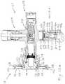
- FIGS. 5 a -5 dare views of components of the showering system of FIG. 1 - FIG. 5 a is a front view, FIG. 5 b is a cross-sectional side view taken along the line 5 b - 5 b in FIG. 5 a , FIG. 5 c is a detailed view of an upper portion of FIG. 5 b , and FIG. 5 d is a detailed view of a lower portion of FIG. 5 b;
- FIGS. 6 a -6 dare views of components of the showering system of FIG. 1 - FIG. 6 a is a front view, FIG. 6 b is a cross-sectional side view taken along the line 6 b - 6 b in FIG. 6 a , FIG. 6 c is a detailed view of an upper portion of FIG. 6 b , and FIG. 6 d is a detailed view of a lower portion of FIG. 6 b;
- FIGS. 7 a -7 dare views of components of the showering system of FIG. 1 - FIG. 7 a is a rear view, FIG. 7 b is a cross-sectional side view taken along the line 7 b - 7 b in FIG. 7 a , FIG. 7 c is a detailed view of an upper portion of FIG. 7 b , and FIG. 7 d is a detailed view of a lower portion of FIG. 7 b;
- FIGS. 8 a -8 bare views of components of the showering system of FIG. 1 - FIG. 8 a is a cross-sectional side view similar to FIG. 5 b , and FIG. 8 b is a detailed view of a circled portion of FIG. 8 a showing an inner shank received in an outer shank;
- FIGS. 9 a -9 bare views of components of the showering system of FIG. 1 - FIG. 9 a is a cross-sectional side view similar to FIG. 8 a , and FIG. 9 b is a detailed view of a circled portion of FIG. 9 a showing the inner shank received in an outermost position in the outer shank;
- FIGS. 10 a -10 bare views of components of the showering system of FIG. 1 - FIG. 10 a is a cross-sectional side view showing the lower mounting assembly mounted on a vertical mounting surface, and FIG. 10 b is a cross-sectional side view showing the lower mounting assembly mounted on a mounting surface two degrees off vertical;
- FIG. 11is a perspective view of components of the lower valving assembly of FIG. 1 ;
- FIG. 12is an exploded perspective view of the components of the lower valving assembly of FIG. 11 ;
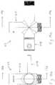
- FIGS. 13 a -13 bare views of the components of the lower valving assembly of FIG. 11 - FIG. 13 a is a front view, and FIG. 13 b is a cross-sectional side view taken along the line 13 b - 13 b in FIG. 13 a;
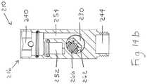
- FIGS. 14 a -14 bare views of the components of the lower valving assembly of FIG. 11 - FIG. 14 a is a side view, and FIG. 14 b is a cross-sectional front view taken along the line 14 b - 14 b in FIG. 14 a ; and
- FIGS. 15 a -15 care views of components of the slide bar assembly, the lower valving assembly, and the handshower assembly of FIG. 1 -
- FIG. 15 ais a cross-sectional perspective view of the components showing fluid flowing to the showerhead
- FIG. 15 bis a cross-sectional perspective view of the components showing fluid flowing to the handshower
- FIG. 15 cis a cross-sectional front view of the components showing fluid flowing to both the showerhead and the handshower at a significantly reduced flow rate.
- the present inventionprovides a plumbing fixture fitting with a diverting system.
- the plumbing fixture fittingis a showering system with a shower rail.
- the diverting systemcould be used in other plumbing fixture fittings.
- An exemplary embodiment of a showering system 10 of the present inventionis shown in FIGS. 1-15 c .
- the showering system 10includes an upper mounting assembly 12 , a lower mounting assembly 14 , an upper valving assembly 16 , a slide bar assembly 18 , a lower valving assembly 20 , a showerhead assembly 22 , and a handshower assembly 24 .
- FIGS. 1-15 cAn exemplary embodiment of the upper mounting assembly 12 is shown in detail in FIGS. 1-15 c , and particularly in FIGS. 3, 5 c , 6 c , 7 c , 8 b , and 9 b . Exemplary components will be described.
- the upper mounting assembly 12includes an inner shank 26 , an outer shank 28 , an upper mounting member 30 , an upper escutcheon 32 , various O-rings, and a set screw.
- the inner shank 26includes a rear end portion 34 and a front end portion 36 .
- the rear end portion 34 of the inner shank 26includes a rear opening 38 and a rear outer surface 40 .
- the rear outer surface 40 of the rear end portion 34 of the inner shank 26is threaded.
- the front end portion 36 of the inner shank 26includes a front opening 42 , a front outer surface 44 , and a shoulder 46 .
- the front outer surface 44 of the front end portion 36 of the inner shank 26includes two O-ring grooves 48 .
- the inner shank 26includes a passageway 50 extending between the rear opening 38 and the front opening 42 in the inner shank 26 .
- the outer shank 28includes a rear end portion 52 and a front end portion 54 .
- the rear end portion 52 of the outer shank 28includes a rear opening 56 , four fingers 58 , a rear outer surface 60 , and a shoulder 62 .
- a free end of each finger 58 on the rear end portion 52 of the outer shank 28includes an inwardly projecting bump 64 .
- the rear outer surface 60 of the rear end portion 52 of the outer shank 28is threaded.
- the front end portion 54 of the outer shank 28includes a front opening 66 and a front outer surface 68 .
- the front outer surface 68 of the front end portion 54 of the outer shank 28includes two O-ring grooves 70 .
- the outer shank 28includes a passageway 72 extending between the rear opening 56 and the front opening 66 in the outer shank 28 .
- the upper mounting member 30includes a back plate 74 , an outer rim 76 , an inner rim 78 , and a central opening 80 .
- the back plate 74 of the upper mounting member 30includes two mounting holes 82 .
- the outer rim 76 of the upper mounting member 30includes an outer surface 84 .
- the outer surface of the outer rim 76 of the upper mounting member 30includes an O-ring groove 86 .
- the inner rim 78 of the upper mounting member 30includes a rear inner surface 88 and a front inner surface 90 .
- the rear inner surface 88 of the inner rim 78 of the upper mounting member 30is tapered.
- the front inner surface 90 of the inner rim 78 of the upper mounting member 30is threaded.
- the upper escutcheon 32includes a central opening 92 .
- the upper mounting member 30is operable to be attached to a mounting surface, such as a shower wall.
- the upper escutcheon 32is operable to be mounted over the upper mounting member 30 .
- the central opening 80 in the upper mounting member 30 and the central opening 92 in the upper escutcheon 32are operable to receive the outer shank 28 extending therethrough.
- the passageway 72 in the outer shank 28is operable to receive the inner shank 26 extending therethrough.
- the passageway 50 in the inner shank 26is operable to receive fluid flowing therethrough from a fluid supply.
- the passageway 72 in the outer shank 28is operable to receive fluid flowing therethrough from the passageway 50 in the inner shank 26 .
- FIGS. 1-15 cAn exemplary embodiment of the lower mounting assembly 14 is shown in detail in FIGS. 1-15 c , and particularly in FIGS. 4, 5 d , 6 d , 7 d , and 10 a - 10 b . Exemplary components will be described.
- the lower mounting assembly 14includes a swivel member 94 , a lower mounting member 96 , a securing member 98 , a lower escutcheon 100 , and various O-rings.
- the swivel member 94includes a rear portion 102 , an intermediate portion 104 , and a front portion 106 .
- the rear portion 102 of the swivel member 94includes a front surface 108 .
- the front surface 108 of the rear portion 102 of the swivel member 94is spherical.
- the intermediate portion 104 of the swivel member 94is generally cylindrical and includes a rear outer surface 110 and a front outer surface 112 .
- the rear outer surface 110 of the intermediate portion 104 of the swivel member 94is non-threaded.
- the front outer surface 112 of the intermediate portion 104 of the swivel member 94is threaded.
- the front portion 106 of the swivel member 94is generally cylindrical and includes an outer surface 114 .
- the outer surface 114 of the front portion 106 of the swivel member 94is threaded.
- the lower mounting member 96includes a back plate 116 , an outer rim 118 , an inner rim 120 , and a central opening 122 .
- the back plate 116 of the lower mounting member 96includes two mounting holes 124 .
- the outer rim 118 of the lower mounting member 96includes an outer surface 126 .
- the outer surface 126 of the outer rim 118 of the lower mounting member 96includes an O-ring groove 128 .
- the inner rim 120 of the lower mounting member 96includes a rear surface 130 , a front surface 132 , and an inner surface 134 .
- the rear surface 130 of the inner rim 120 of the lower mounting member 96is spherical.
- the front surface 132 of the inner rim 120 of the lower mounting member 96is spherical.
- the inner surface 134 of the inner rim 120 of the lower mounting member 96is threaded.
- the securing member 98includes a rear portion 136 , a front portion 138 , and a central opening 140 .
- the rear portion 136 of the securing member 98includes a rear surface 142 .
- the rear surface 142 of the rear portion 136 of the securing member 98is spherical.
- the front portion 138 of the securing member 98includes an inner surface 144 .
- the inner surface 144 of the front portion 138 of the securing member 98is threaded.
- the lower escutcheon 100includes a central opening 146 .
- the intermediate portion 104 of the swivel member 94is operable to extend through the central opening 122 in the lower mounting member 96 .
- the spherical front surface 108 of the rear portion 102 of the swivel member 94is operable to abut the spherical rear surface 130 of the inner rim 120 of the lower mounting member 96 .
- the lower mounting member 96is operable to be attached to the mounting surface.
- the spherical front surface 132 of the inner rim 120 of the lower mounting member 96is operable to abut the spherical rear surface 142 of the rear portion 136 of the securing member 98 .
- the threaded outer surface 114 of the front portion 106 of the swivel member 94is operable to be threaded into the lower valving assembly 20 .
- the threaded inner surface 144 of the front portion 138 of the securing member 98is operable to be threaded onto the lower valving assembly 20 .
- the lower escutcheon 100is operable to be mounted over the swivel member 94 , the lower mounting member 96 , and the securing member 98 .
- the upper valving assembly 16includes an upper valve body 148 , an O-ring, and a set screw.
- the upper valve body 148includes an upper valve housing 150 and an upper valve insert 152 .
- the upper valve housing 150includes a longitudinal portion 154 and a transverse portion 156 .
- the longitudinal portion 154 of the upper valve housing 150includes a rear end portion 158 and a front end portion 160 .
- the rear end portion 158 of the longitudinal portion 154 of the upper valve housing 150includes a rear opening 162 .
- the front end portion 160 of the longitudinal portion 154 of the upper valve housing 150includes a front opening 164 .
- the longitudinal portion 154 of the upper valve housing 150includes a longitudinal bore 166 extending inwardly from the rear opening 162 .
- the longitudinal bore 166 in the longitudinal portion 154 of the upper valve housing 150is operable to receive the outer shank 28 .
- the longitudinal bore 166 in the longitudinal portion 154 of the upper valve housing 150is operable to receive fluid flowing therethrough from the passageway 72 in the outer shank 28 .
- the transverse portion 156 of the upper valve housing 150includes a bottom end portion 168 .
- the bottom end portion 168 of the transverse portion 156 of the upper valve housing 150includes a bottom opening 170 .
- the transverse portion 156 of the upper valve housing 150includes a transverse bore 172 extending inwardly from the bottom opening 170 and a tube passageway 174 extending inwardly from the transverse bore 172 .
- the transverse bore 172 in the transverse portion 156 of the upper valve housing 150is operable to receive the upper valve insert 152 .
- the upper valve insert 152includes a tube passageway 176 and a flow passageway 178 .
- the flow passageway 178 in the upper valve insert 152is in fluid communication with the longitudinal bore 166 in the longitudinal portion 154 of the upper valve housing 150 via a first passageway 180 in the upper valve housing 150 .
- the slide bar assembly 18includes an outer tube 182 , an inner tube 184 , and a slider cradle 186 .
- the outer tube 182includes an upper end portion 188 and a lower end portion 190 .
- the upper end portion 188 of the outer tube 182includes an upper opening 192 .
- the lower end portion 190 of the outer tube 182includes a lower opening 194 .
- the outer tube 182is hollow between the upper opening 192 and the lower opening 194 , and is operable to have fluid flow therethrough.
- the inner tube 184includes an upper end portion 196 and a lower end portion 198 .
- the upper end portion 196 of the inner tube 184includes an upper opening 200 .
- the lower end portion 198 of the inner tube 184includes a lower opening 202 .
- the inner tube 184is hollow between the upper opening 200 and the lower opening 202 , and is operable to have fluid flow therethrough.
- the upper end portion 196 of the inner tube 184is operable to be received in the tube passageway 176 in the upper valve insert 152 and the tube passageway 174 in the transverse portion 156 of the upper valve housing 150 .
- the slider cradle 186is operable to be slid on the outer tube 182 .
- the lower valving assembly 20includes a lower valve body 204 , a diverter assembly 206 , a handle assembly 208 , various O-rings, and a set screw.
- the lower valve body 204includes a lower valve housing 210 and a lower valve insert 212 .
- the lower valve housing 210includes a longitudinal portion 214 and a transverse portion 216 .
- the longitudinal portion 214 of the lower valve housing 210includes a rear end portion 218 and a front end portion 220 .
- the rear end portion 218 of the longitudinal portion 214 of the lower valve housing 210includes a rear opening 222 , an inner surface 224 , and an outer surface 226 .
- the inner surface 224 of the rear end portion 218 of the longitudinal portion 214 of the lower valve housing 210is threaded.
- the outer surface 226 of the rear end portion 218 of the longitudinal portion 214 of the lower valve housing 210is threaded.
- the front end portion 220 of the longitudinal portion 214 of the lower valve housing 210includes a front opening 228 .
- the longitudinal portion 214 of the lower valve housing 210includes a longitudinal bore 230 extending between the rear opening 222 and the front opening 228 .
- the longitudinal bore 230 in the longitudinal portion 214 of the lower valve housing 210includes a shoulder 232 .
- the transverse portion 216 of the lower valve housing 210includes a top end portion 234 and a bottom end portion 236 .
- the transverse portion 216 of the lower valve housing 210has a central longitudinal axis.
- the top end portion 234 of the transverse portion 216 of the lower valve housing 210includes a top opening 238 and a top cavity 240 extending inwardly from the top opening 238 .
- the bottom end portion 236 of the transverse portion 216 of the lower valve housing 210includes a bottom opening 242 , a bottom cavity 244 extending inwardly from the bottom opening 242 , and an outer surface 246 .
- the outer surface 246 of the bottom end portion 236 of the transverse portion 216 of the lower valve housing 210is threaded.
- the top cavity 240 in the top end portion 234 of the transverse portion 216 of the lower valve housing 210is operable to receive the lower valve insert 212 .
- the lower valve insert 212includes a tube passageway 248 and a flow passageway 250 .
- the transverse portion 216 of the lower valve housing 210includes a tube passageway 252 , a flow passageway 254 , an upper or first port 256 , and a lower or second port 258 .
- the first port 256includes a central longitudinal axis.
- the second port 258includes a central longitudinal axis.
- the central longitudinal axis of the first port 256 and the central longitudinal axis of the second port 258are offset from the central longitudinal axis of the transverse portion 216 of the lower valve housing 210 .
- the central longitudinal axis of the first port 256 and the central longitudinal axis of the second port 258are aligned with each other, but could be offset from each other.
- the tube passageway 248 in the lower valve insert 212 and the tube passageway 252 in the transverse portion 216 of the lower valve housing 210are operable to receive the lower end portion 198 of the inner tube 184 .
- the flow passageway 250 in the lower valve insert 212is in fluid communication with the flow passageway 254 in the transverse portion 216 of the lower valve housing 210 .
- the flow passageway 254 in the lower valve housing 210is in fluid communication with the longitudinal bore 230 in the longitudinal portion 214 of the lower valve housing 210 .
- the longitudinal bore 230 in the longitudinal portion 214 of the lower valve housing 210is in fluid communication with the first port 256 and the second port 258 in the transverse portion 216 of the lower valve housing 210 .
- the first port 256 in the transverse portion 216 of the lower valve housing 210is in fluid communication with the inner tube 184 .
- the second port 258 in the transverse portion 216 of the lower valve housing 210is in fluid communication with the bottom cavity 244 in the bottom end portion 236 of the transverse portion 216 of the lower valve housing 210 .
- the diverter assembly 206includes a diverter nut 260 , a diverter spool 262 , a diverter spring 264 , and a diverter seal 266 .
- the diverter nut 260includes a rear end portion 268 and a front end portion 270 .
- the rear end portion 268 of the diverter nut 260includes four fingers 272 and a rear outer surface 274 .
- the rear outer surface 274 of the rear end portion 268 of the diverter nut 260is threaded.
- the front end portion 270 of the diverter nut 260includes a shoulder 276 .
- the diverter spool 262includes a cavity 278 , an outer surface 280 , and a front end portion 282 .
- the cavity 278 in the diverter spool 262is operable to receive the diverter spring 264 and the diverter seal 266 .
- the outer surface 280 of the diverter spool 262includes two O-ring grooves 284 , with one O-ring groove 284 located on each side of the cavity 278 .
- the front end portion 282 of the diverter spool 262includes a bore 286 .
- the bore 286 in the front end portion 282 of the diverter spool 262is threaded.
- the diverter spool 262(with the diverter spring 264 and the diverter seal 266 therein) is operable to be inserted through the rear opening 222 in the rear end portion 218 of the longitudinal portion 214 of the lower valve housing 210 and received in the longitudinal bore 230 in the longitudinal portion 214 of the lower valve housing 210 .
- the diverter nut 260is operable to be inserted through the rear opening 222 in the rear end portion 218 of the longitudinal portion 214 of the lower valve housing 210 and threaded into the rear end portion 218 of the longitudinal portion 214 of the lower valve housing 210 until the shoulder 276 on the front end portion 270 of the diverter nut 260 abuts the shoulder 232 in the longitudinal bore 230 in the longitudinal portion 214 of the lower valve housing 210 .
- the diverter nut 260is operable to secure the diverter spool 262 in the longitudinal bore 230 in the longitudinal portion 214 of the lower valve housing 210 .
- the handle assembly 208includes a handle base 288 , a handle cap 290 , and a handle screw 292 .
- the handle base 288includes a rear end portion 294 , a front end portion 296 , and a handle bat 298 .
- the rear end portion 294 of the handle base 288is operable to be attached to the diverter spool 262 via the handle screw 292 and the threaded bore 286 in the front end portion 282 of the diverter spool 262 .
- the handle cap 290is operable to snap into the front end portion 296 of the handle base 288 .
- the handle assembly 208is operable to rotate the diverter spool 262 (with the diverter spring 264 and the diverter seal 266 therein) within the longitudinal bore 230 in the longitudinal portion 214 of the lower valve housing 210 and divert fluid flow from the flow passageway 254 in the transverse portion 216 of the lower valve housing 210 to the first port 256 and the second port 258 in the transverse portion 216 of the lower valve housing 210 .
- the showerhead assembly 22includes a shower arm 300 and a showerhead 302 .
- the shower arm 300includes a rear end portion 304 and a front end portion 306 .
- the rear end portion 304 of the shower arm 300includes a rear opening 308 .
- the front end portion 306 of the shower arm 300includes a front opening 310 .
- the shower arm 300is hollow between the rear opening 308 and the front opening 310 , and is operable to have fluid flow therethrough.
- the shower arm 300is operable to be threaded into the front end portion 160 of the longitudinal portion 154 of the upper valve housing 150 .
- the shower arm 300is in fluid communication with the inner tube 184 via a second passageway 312 in the upper valve housing 150 .
- the front end portion 306 of the shower arm 300is operable to be threaded into the showerhead 302 .
- the showerhead 302is in fluid communication with the shower arm 300 .
- the handshower assembly 24includes an elbow assembly 314 , a hose 316 , and a handshower 318 .
- the elbow assembly 314includes a gasket seal 320 , a washer 322 , a check valve 324 , an elbow insert 326 , a lock ring 328 , an elbow nut 330 , an elbow housing 332 , and various O-rings.
- the elbow housing 332includes a top end portion 334 and a bottom end portion 336 .
- the top end portion 334 of the elbow housing 332includes a top opening 338 and an inner surface 340 .
- the inner surface 340 of the top end portion 334 of the elbow housing 332includes a lock groove 342 .
- the bottom end portion 336 of the elbow housing 332includes a bottom opening 344 and an outer surface 346 .
- the outer surface 346 of the bottom end portion 336 of the elbow housing 332is threaded.
- the elbow housing 332includes a passageway 348 extending between the top opening 338 and the bottom opening 344 .
- the elbow insert 326includes a top end portion 350 and a bottom end portion 352 .
- the top end portion 350 of the elbow insert 326includes a top opening 354 and an outer surface 356 .
- the outer surface 356 of the top end portion 350 of the elbow insert 326includes a flange 358 .
- the bottom end portion 352 of the elbow insert 326includes a bottom opening 360 and an outer surface 362 .
- the outer surface 362 of the bottom end portion 352 of the elbow insert 326includes two O-ring grooves 364 and a lock groove 366 .
- the elbow insert 326includes a passageway 368 between the top opening 354 and the bottom opening 360 .
- the elbow nut 330includes a top end portion 370 , a bottom end portion 372 , and a central opening 374 .
- the top end portion 370 of the elbow nut 330includes an inner surface 376 .
- the inner surface 376 of the top end portion 370 of the elbow nut 330is threaded.
- the bottom end portion 372 of the elbow nut 330includes an inner surface 378 .
- the inner surface 378 of the bottom end portion 372 of the elbow nut 330includes a flange 380 .
- the lock ring 328is operable to be inserted into the lock groove 366 in the bottom end portion 352 of the elbow insert 326 .
- the elbow insert 326(with the O-rings and the lock ring 328 thereon) is operable to be inserted through the central opening 374 in the elbow nut 330 until the flange 358 on the outer surface 356 of the top end portion 350 of the elbow insert 326 abuts the flange 380 on the inner surface 378 of the bottom end portion 372 of the elbow nut 330 .
- the elbow insert 326(with the O-rings and the lock ring 328 thereon) is operable to be inserted through the top opening 338 in the top end portion 334 of the elbow housing 332 and into the passageway 348 in the elbow housing 332 until the lock ring 328 snaps into the lock groove 342 in the inner surface 340 of the top end portion 334 of the elbow housing 332 .
- the lock ring 328is operable to retain the elbow insert 326 in the passageway 348 in the elbow housing 332 .
- the check valve 324 , the washer 322 , and the gasket seal 320are operable to be inserted into the top end portion 350 of the elbow insert 326 .
- the elbow nut 330is operable to be threaded onto the bottom end portion 236 of the transverse portion 216 of the lower valve housing 210 .
- the elbow nut 330is operable to connect the elbow housing 332 to the bottom end portion 236 of the transverse portion 216 of the lower valve housing 210 .
- the hose 316includes an upstream end 382 and a downstream end 384 .
- the upstream end 382 of the hose 316includes a threaded connector.
- the upstream end 382 of the hose 316is operable to be threaded onto the bottom end portion 336 of the elbow housing 332 .
- the downstream end 384 of the hose 316includes a threaded connector.
- the downstream end 384 of the hose 316is operable to be threaded onto the handshower 318 .
- the handshower 318is operable to be received in the slider cradle 186 .
- the O-ringsare placed in the O-ring grooves 284 in the outer surface 280 of the diverter spool 262 , and the diverter spring 264 and the diverter seal 266 are inserted into the cavity 278 in the diverter spool 262 .
- the diverter spool 262(with the O-rings thereon and the diverter spring 264 and the diverter seal 266 therein) is inserted through the rear opening 222 in the rear end portion 218 of the longitudinal portion 214 of the lower valve housing 210 and into the longitudinal bore 230 in the longitudinal portion 214 of the lower valve housing 210 .
- the diverter nut 260is inserted through the rear opening 222 in the rear end portion 218 of the longitudinal portion 214 of the lower valve housing 210 and threaded into the rear end portion 218 of the longitudinal portion 214 of the lower valve housing 210 .
- the rear end portion 294 of the handle base 288is placed on the front end portion 220 of the longitudinal portion 214 of the lower valve housing 210 and secured to the diverter spool 262 via the handle screw 292 and the threaded bore 286 in the front end portion 282 of the diverter spool 262 .
- the handle cap 290is snapped into the front end portion 296 of the handle base 288 .
- components of the handshower assembly 24are preassembled. Exemplary assembly steps will be described.
- the O-ringsare placed in the O-ring grooves 364 in the outer surface 362 of the bottom end portion 352 of the elbow insert 326
- the lock ring 328is placed in the lock groove 366 in the outer surface 362 of the bottom end portion 352 of the elbow insert 326 .
- the elbow insert 326(with the O-rings and the lock ring 328 thereon) is inserted from the top end portion 370 of the elbow nut 330 into the central opening 374 in the elbow nut 330 until the flange 358 on the outer surface 356 of the top end portion 350 of the elbow insert 326 abuts the flange 380 on the inner surface 378 of the bottom end portion 372 of the elbow nut 330 .
- the elbow insert 326(with the O-rings and the lock ring 328 thereon) is inserted through the top opening 338 in the top end portion 334 of the elbow housing 332 into the passageway 348 in the elbow housing 332 until the lock ring 328 snaps into the lock groove 342 in the inner surface 340 of the top end portion 334 of the elbow housing 332 .
- the check valve 324 , the washer 322 , and the gasket seal 320are inserted through the top opening 354 in the top end portion 350 of the elbow insert 326 and into the passageway 368 in the elbow insert 326 .
- the top end portion 370 of the elbow nut 330is threaded onto the bottom end portion 236 of the transverse portion 216 of the lower valve housing 210 .
- the intermediate portion 104 of the swivel member 94is threaded through the inner rim 120 of the lower mounting member 96 until the threaded front outer surface 112 of the intermediate portion 104 of the swivel member 94 no longer engages the threaded inner surface 134 of the inner rim 120 of the lower mounting member 96 and the non-threaded rear outer surface 110 of the intermediate portion 104 of the swivel member 94 extends through the inner rim 120 of the lower mounting member 96 .
- the upper valve insert 152is secured in the upper end portion 188 of the outer tube 182 via brazing.
- the lower valve insert 212is secured in the lower end portion 190 of the outer tube 182 via brazing.
- the inner tube 184is inserted into the tube passageway 176 in the upper valve insert 152 , the outer tube 182 , and the tube passageway 248 in the lower valve insert 212 .
- the slider cradle 186is placed over the outer tube 182 .
- the bottom end portion 168 of the transverse portion 156 of the upper valve housing 150is placed over the upper valve insert 152 such that the upper valve insert 152 is received in the transverse bore 172 in the transverse portion 156 of the upper valve housing 150 and the upper end portion 196 of the inner tube 184 is received in the tube passageway 174 in the transverse portion 156 of the upper valve housing 150 .
- the top end portion 234 of the transverse portion 216 of the lower valve housing 210is placed over the lower valve insert 212 such that the lower valve insert 212 is received in the top cavity 240 in the top end portion 234 of the transverse portion 216 of the lower valve housing 210 and the lower end portion 198 of the inner tube 184 is received in the tube passageway 252 in the transverse portion 216 of the lower valve housing 210 .
- the front portion 106 of the swivel member 94is threaded into the rear end portion 218 of the longitudinal portion 214 of the lower valve housing 210 .
- FIGS. 1-15 ccomponents of the upper mounting assembly 12 are installed. Exemplary installation steps will be described.
- the rear end portion 34 of the inner shank 26is threaded into an elbow of the water supply behind the mounting surface.
- the upper mounting member 30is placed over the inner shank 26 with the inner shank 26 extending through the central opening 80 in the upper mounting member 30 .
- the upper mounting member 30is attached to the mounting surface via screws through the mounting holes 82 in the back plate 74 of the upper mounting member 30 .
- the rear end portion 52 of the outer shank 28is placed over the front end portion 36 of the inner shank 26 .
- the rear end portion 52 of the outer shank 28is threaded into the inner rim 78 of the upper mounting member 30 until the shoulder 62 on the rear end portion 52 of the outer shank 28 abuts the inner rim 78 of the upper mounting member 30 .
- the fingers 58 on the rear end portion 52 of the outer shank 28deform (e.g., plastically) inside the tapered rear inner surface 88 of the inner rim 78 of the upper mounting member 30 .
- the preassembled components of the upper valving assembly 16 , the slide bar assembly 18 , the lower valving assembly 20 , and the lower mounting assembly 14are installed. Exemplary installation steps will be described.
- the rear end portion 158 of the longitudinal portion 154 of the upper valve housing 150is placed over the outer shank 28 such that the preassembled components are in position relative to the mounting surface.
- the preassembled componentsare leveled both vertically and horizontally. Markings are made on the mounting surface through the mounting holes 124 in the back plate 116 of the lower mounting member 96 .
- the rear end portion 158 of the longitudinal portion 154 of the upper valve housing 150is removed from the outer shank 28 such that the preassembled components are no longer in position relative to the mounting surface.
- the front portion 106 of the swivel member 94is threaded out of the rear end portion 218 of the longitudinal portion 214 of the lower valve housing 210 .
- the swivel member 94is still connected to the lower mounting member 96 with the non-threaded rear outer surface 110 of the intermediate portion 104 of the swivel member 94 extending through the inner rim 120 of the lower mounting member 96 .
- the lower mounting member 96(with the swivel member 94 connected thereto) is attached to the mounting surface via screws through the mounting holes 124 in the back plate 116 of the lower mounting member 96 .
- the upper escutcheon 32is placed on the rear end portion 158 of the longitudinal portion 154 of the upper valve housing 150 .
- the lower escutcheon 100is placed on the rear end portion 218 of the longitudinal portion 214 of the lower valve housing 210 .
- the securing member 98is threaded onto the rear end portion 218 of the longitudinal portion 214 of the lower valve housing 210 .
- the rear end portion 158 of the longitudinal portion 154 of the upper valve housing 150is again placed over the outer shank 28 such that the preassembled components are in position relative to the mounting surface.
- the rear opening 222 in the rear end portion 218 of the longitudinal portion 214 of the lower valve housing 210is aligned with the front portion 106 of the swivel member 94 .
- the front portion 106 of the swivel member 94is threaded into the rear end portion 218 of the longitudinal portion 214 of the lower valve housing 210 pulling the lower valve housing 210 toward the mounting surface.
- the securing member 98is threaded toward the mounting surface until the at least a portion of the spherical rear surface 142 of the rear portion 136 of the securing member 98 abuts the spherical front surface 132 of the inner rim 120 of the lower mounting member 96 .
- the upper valve housing 150is secured relative to the outer shank 28 via a set screw. Because the swivel member 94 is free to rotate within the lower mounting member 96 , the slide bar assembly 18 can be mounted in a vertical orientation even when the mounting surface is off from vertical.
- abutting surfaces of the lower mounting assembly 14i.e., the front surface 108 of the rear portion 102 of the swivel member 94 , the rear surface 130 of the inner rim 120 of the lower mounting member 96 , the front surface 132 of the inner rim 120 of the lower mounting member 96 , and the rear surface 142 of the rear portion 136 of the securing member 98
- these abutting surfacesmay not be spherical.
- these abutting surfacesmay be other shapes, such as conical, so long as the shape of the abutting surfaces allows the surfaces to rotate relative to each other.
- the shape of these abutting surfacesmay be described as angled.
- angled surfacesinclude curved angle surfaces.
- the showerhead 302is selected by rotating the handle assembly 208 to a first position (which rotates the diverter assembly 206 to a corresponding first position), the water then flows through the components of the showering system 10 as follows: (1) through the first port 256 , (2) through the inner tube 184 , (3) through the second passageway 312 in the upper valve housing 150 , (4) through the shower arm 300 , and (5) through the showerhead 302 .
- the diverter assembly 206allows full flow of water through the first port 256 .
- the waterthen flows through the components of the showering system 10 as follows: (1) through the second port 258 , (2) through the bottom cavity 242 in the bottom end portion 236 of the transverse portion 216 of the lower valve housing 210 , (3) through the check valve 324 , (4) through the passageway 368 in the elbow insert 326 , (5) through the passageway 348 in the elbow housing 332 , (6) through the hose 316 , and (7) through the handshower 318 .
- the diverter assembly 206allows full flow of water through the second port 258 .
- rotation of the handle assembly 208 (and thus the diverter assembly 206 ) from the first position to the second positionrequires less than one-hundred eighty degrees of rotation. In the illustrated embodiment, rotation of the handle assembly 208 (and thus the diverter assembly 206 ) from the first position to the second position only requires ninety degrees of rotation.
- the handle assembly 208When the handle assembly 208 is rotated to a position in the middle of the first position and the second position (which rotates the diverter assembly 206 to a corresponding middle position), the water then flows through both the first port 256 and the second port 258 and through both the showerhead 302 and the handshower 318 . However, in the middle position, the flow through the first port 256 and the second port 258 is at a significantly reduced flow rate.
- showering system 10has been shown and described in the illustrated embodiment as including certain components, one of ordinary skill in the art will appreciate that the showering system 10 does not need to include each of these components.
- the upper valving assembly 16 and the lower valving assembly 20have been described as including the upper valve body 148 and the lower valve body 204 , respectively.
- the upper valve body 148has been described as including the upper valve housing 150 and the upper valve insert 152
- the lower valve body 204has been described as including the lower valve housing 210 and the lower valve insert 212 .
- the upper valve insert 152could be integrally formed with the upper valve housing 150
- the lower valve insert 212could be integrally formed with the lower valve housing 210
- the upper valve insert 152 and the lower valve insert 212could be integrally formed with the outer tube 182 .
- showering system 10has been shown and described in the illustrated embodiment with the components attached or engaged in a particular manner, one of ordinary skill in the art will appreciate that the components of the showering system 10 do not need to be attached or engaged in this particular manner.
Landscapes
- Engineering & Computer Science (AREA)
- General Engineering & Computer Science (AREA)
- Health & Medical Sciences (AREA)
- Life Sciences & Earth Sciences (AREA)
- Hydrology & Water Resources (AREA)
- Public Health (AREA)
- Water Supply & Treatment (AREA)
- Mechanical Engineering (AREA)
- Valve Housings (AREA)
Abstract
Description
Claims (2)
Priority Applications (1)
| Application Number | Priority Date | Filing Date | Title |
|---|---|---|---|
| US15/582,604US10570592B2 (en) | 2016-04-29 | 2017-04-29 | Plumbing fixture fitting with diverting system |
Applications Claiming Priority (2)
| Application Number | Priority Date | Filing Date | Title |
|---|---|---|---|
| US201662329748P | 2016-04-29 | 2016-04-29 | |
| US15/582,604US10570592B2 (en) | 2016-04-29 | 2017-04-29 | Plumbing fixture fitting with diverting system |
Publications (2)
| Publication Number | Publication Date |
|---|---|
| US20170312768A1 US20170312768A1 (en) | 2017-11-02 |
| US10570592B2true US10570592B2 (en) | 2020-02-25 |
Family
ID=60157213
Family Applications (2)
| Application Number | Title | Priority Date | Filing Date |
|---|---|---|---|
| US15/582,600Active2037-07-08US10352025B2 (en) | 2016-04-29 | 2017-04-28 | Plumbing fixture fitting with mounting system |
| US15/582,604ActiveUS10570592B2 (en) | 2016-04-29 | 2017-04-29 | Plumbing fixture fitting with diverting system |
Family Applications Before (1)
| Application Number | Title | Priority Date | Filing Date |
|---|---|---|---|
| US15/582,600Active2037-07-08US10352025B2 (en) | 2016-04-29 | 2017-04-28 | Plumbing fixture fitting with mounting system |
Country Status (1)
| Country | Link |
|---|---|
| US (2) | US10352025B2 (en) |
Cited By (2)
| Publication number | Priority date | Publication date | Assignee | Title |
|---|---|---|---|---|
| US11731155B2 (en) | 2021-01-26 | 2023-08-22 | Loura Holdings, Llc | Method and apparatus for stabilizing a loose showerhead assembly |
| USD1050110S1 (en) | 2022-02-08 | 2024-11-05 | Boundless EC US LLC | Handheld shower nozzle |
Families Citing this family (20)
| Publication number | Priority date | Publication date | Assignee | Title |
|---|---|---|---|---|
| CN103328733B (en)* | 2010-12-17 | 2016-08-10 | 科勒公司 | shower column system |
| USD884122S1 (en)* | 2018-01-24 | 2020-05-12 | Grohe Ag | Shower system |
| US11241072B2 (en)* | 2018-04-13 | 2022-02-08 | Jean LaPoint | Universal bathroom holder |
| US10962123B2 (en)* | 2018-04-23 | 2021-03-30 | Sioux Chief Mfg. Co., Inc. | Push-fit spigot |
| CN108691334B (en)* | 2018-06-22 | 2025-02-28 | 厦门建霖健康家居股份有限公司 | A liftable shower device |
| US11499300B2 (en) | 2019-02-15 | 2022-11-15 | Spectrum Brands, Inc. | Shower column assembly |
| US11555548B2 (en) | 2019-10-07 | 2023-01-17 | Masco Canada Limited | Mixing valves, valve modules, and valve module assemblies |
| CN215390283U (en)* | 2020-11-02 | 2022-01-04 | 九牧厨卫股份有限公司 | Slide rail assembly and gondola water faucet subassembly |
| USD963111S1 (en)* | 2021-01-06 | 2022-09-06 | Xiamen Delmei Sanitaryware Co., Ltd. | Shower apparatus |
| USD922532S1 (en)* | 2021-02-19 | 2021-06-15 | Na Pan | Exposed shower fixture |
| CN214738474U (en)* | 2021-04-21 | 2021-11-16 | 厦门市博进工贸有限公司 | Novel multifunctional shower support arm |
| US11484467B1 (en)* | 2021-04-26 | 2022-11-01 | Waterway Plastics | Compensation ring/load washer for spa fittings |
| KR102690448B1 (en)* | 2022-05-20 | 2024-07-30 | 박명수 | Shower head fixing bracket |
| USD1042736S1 (en)* | 2022-06-20 | 2024-09-17 | Xiamen Delmei Sanitary Ware Co., Ltd | Shower head |
| USD1055238S1 (en)* | 2022-07-04 | 2024-12-24 | Xiamen Delmei Sanitary Ware Co., Ltd. | Three-way pipe connector |
| CN218933323U (en)* | 2022-11-14 | 2023-04-28 | 沛乐迪(厦门)卫浴有限公司 | Shower support and easy-to-use combined shower head |
| USD1065462S1 (en)* | 2023-02-22 | 2025-03-04 | Shengwu ZHANG | Extension rod for shower |
| US12285140B2 (en)* | 2023-02-22 | 2025-04-29 | Raymond Armbrister | Showerhead attachment and methods of use |
| US20250295276A1 (en)* | 2024-03-19 | 2025-09-25 | Yongzhe Ma | Bathing device |
| USD1047084S1 (en)* | 2024-06-10 | 2024-10-15 | Suwen Wang | Shower panel |
Citations (87)
| Publication number | Priority date | Publication date | Assignee | Title |
|---|---|---|---|---|
| US999332A (en)* | 1911-03-28 | 1911-08-01 | Mueller Mfg Co H | Adjustable sleeve-nut and flange. |
| US1758115A (en) | 1929-01-12 | 1930-05-13 | James W Kelly | Adjustable shower fixture |
| US1799815A (en) | 1930-02-12 | 1931-04-07 | Halfdan Bjorn | Shower-bath device |
| US2228626A (en) | 1938-05-07 | 1941-01-14 | Hetherington Robert | Shower unit |
| US2759765A (en) | 1954-07-19 | 1956-08-21 | Leon P Pawley | Flexible shower head |
| US2846691A (en) | 1956-11-19 | 1958-08-12 | Milwaukee Faucets | Spout-shower plumbing fixture |
| US3136570A (en) | 1960-08-12 | 1964-06-09 | Sunnyview Invest Corp | Adapter for nipple on bath tub spout |
| US3188120A (en) | 1964-10-21 | 1965-06-08 | Chester H Peterson | Adjustable pipe nipple |
| GB1046746A (en) | 1963-08-27 | 1966-10-26 | Hans Grohe Handelsgesellschaft | Improvements in or relating to wall supports for shower fittings |
| GB1401437A (en) | 1971-10-29 | 1975-07-16 | Crosweller & Co Ltd W | Ablutionary appliances |
| US3913839A (en) | 1975-01-23 | 1975-10-21 | Mark L Wilson | Dual shower attachment device |
| DE2601059B1 (en) | 1976-01-13 | 1977-07-14 | Kilb & Brandenburg | Height adjustable shower fastening - has telescopic length adjustable water supply pipe |
| FR2416308A1 (en) | 1978-02-01 | 1979-08-31 | Valentin Sa | Vertical wall rail for shower bath attachment - fitted with shower rose carrier, slide grip and polyethylene pull cords |
| GB2073585A (en) | 1980-03-28 | 1981-10-21 | Floyd G W | Domestic shower supplies |
| GB2109226A (en) | 1981-11-12 | 1983-06-02 | Gevipi Ag | Shower support |
| US4457342A (en) | 1982-06-01 | 1984-07-03 | Stanadyne, Inc. | High rise kitchen spout |
| FR2606296A1 (en) | 1986-10-09 | 1988-05-13 | Delepine Jean C | Rail for spraying a fluid |
| EP0308694A1 (en) | 1987-09-25 | 1989-03-29 | Oras Oy | Shower rod |
| US4890817A (en)* | 1987-05-15 | 1990-01-02 | Plasson Maagan Michael Industries, Ltd. | Quarter-turn valve |
| JPH02112758A (en) | 1988-10-21 | 1990-04-25 | Toshiba Corp | Ultrasonic flaw detection equipment |
| US4997007A (en)* | 1990-01-18 | 1991-03-05 | Masco Corporation Of Indiana | Shower diverter valve |
| US5305916A (en) | 1991-12-09 | 1994-04-26 | Kabushiki Kaisha San-Ai | Drip free, volume-adjustable, automatic liquid dispenser |
| US5329650A (en) | 1992-03-06 | 1994-07-19 | Herman Miller, Inc. | Shower stall control column |
| FR2713301A1 (en) | 1993-12-02 | 1995-06-09 | Saneurop | Support bar for shower head with vertical adjustment |
| WO1998002077A1 (en) | 1996-07-13 | 1998-01-22 | Daryl Industries Limited | Shower apparatus comprising multiple shower heads and diverter |
| US5829469A (en) | 1995-10-10 | 1998-11-03 | Joseph P. Sileno, Jr. Revocable Trust | Apparatus for retrofitting a non-pressure balanced mixing valve to provide pressure balanced operation |
| US5870781A (en) | 1997-06-27 | 1999-02-16 | Williams; Alex | Adjustable shower track system |
| US6038715A (en) | 1997-05-23 | 2000-03-21 | Hansgrohe Ag | Multiple shower combination |
| US6175972B1 (en) | 1997-07-30 | 2001-01-23 | Resources Conservation, Inc. | Kit for installing bath spouts |
| US6192529B1 (en) | 2000-02-18 | 2001-02-27 | Moen Incorporated | Modular shower arm construction |
| US6264121B1 (en) | 1997-05-13 | 2001-07-24 | Mcclary Nobia | Adjustable hand-held shower apparatus |
| US6276004B1 (en) | 2000-02-15 | 2001-08-21 | Moen Incorporated | Shower arm mounting |
| US6301727B1 (en) | 2000-04-10 | 2001-10-16 | Moen Incorporated | Modular tub spout assembly |
| CA2337671A1 (en) | 2000-07-26 | 2002-01-26 | Jackson Chen | Adjustable shower arm assembly |
| US20020040500A1 (en) | 2000-06-29 | 2002-04-11 | Masao Noguchi | Water shower apparatus |
| US6438767B1 (en) | 2001-04-26 | 2002-08-27 | I. W. Industries, Inc. | Adjustable height showerhead |
| US6464265B1 (en) | 1999-10-22 | 2002-10-15 | Moen Incorporated | Modular shower arm mounting system |
| WO2003066976A1 (en) | 2002-02-06 | 2003-08-14 | Toto Ltd. | Water discharge device |
| US6643862B2 (en) | 2001-12-17 | 2003-11-11 | Theodore M. Aitken | Body shower kit |
| US6668393B1 (en) | 2002-07-23 | 2003-12-30 | Moen Incorporated | Height adjustable diverter spout assembly |
| EP1405955A2 (en) | 2002-10-02 | 2004-04-07 | American Standard Europe B.V.B.A. | Water delivery means in sanitary systems |
| US20040134924A1 (en) | 2002-06-03 | 2004-07-15 | Alwin Manufacturing Co., Inc. | Automatic dispenser apparatus |
| US20050063772A1 (en) | 2003-03-20 | 2005-03-24 | Bladen Roy Victor | Connection assembly apparatus and method |
| WO2005031073A1 (en) | 2003-09-30 | 2005-04-07 | Rubinetterie Cristina S.P.A. | Shower column |
| US20060021131A1 (en) | 2004-07-30 | 2006-02-02 | Magarl, Llc | System and method for providing tempered fluid |
| US7043776B1 (en) | 2005-02-28 | 2006-05-16 | Chao-Chang Wu | Shower assembly |
| US20060150314A1 (en) | 2003-03-18 | 2006-07-13 | Horst Flieger | Shower arrangement |
| DE102005004788A1 (en) | 2005-02-01 | 2006-08-10 | Grohe Ag | Rod for sanitary shower device, has head shower provided at hollow rod that is arranged perpendicularly to side wall, and U-shaped tube bracket connected to hollow rod in sealed manner, where shower is attached to free end of bracket |
| US20060196972A1 (en) | 2005-03-01 | 2006-09-07 | Kohler Co. | Bodyspray having adjustable spray orientation |
| GB2433885A (en) | 2006-01-07 | 2007-07-11 | Bristan Ltd | Shower with back flow prevention |
| US20070199144A1 (en) | 2004-02-25 | 2007-08-30 | Guenter Glunk | Shower Arrangement |
| US7273070B2 (en) | 2005-11-28 | 2007-09-25 | Tung-Po Lin | Spout plumbing device |
| USD559949S1 (en) | 2007-05-03 | 2008-01-15 | Brasstech, Inc. | Shower assembly |
| US20080083844A1 (en) | 2006-10-09 | 2008-04-10 | Water Pik, Inc. | Showerhead attachment assembly |
| US7458112B1 (en) | 2008-03-24 | 2008-12-02 | Ue-Ming Yang | Shower assembly kit with multiple functions |
| CN201248644Y (en) | 2008-07-30 | 2009-06-03 | 伟美(厦门)淋浴设备有限公司 | Novel drilling-free shower system |
| US7614424B2 (en) | 2005-03-11 | 2009-11-10 | Kwc Ag | Sanitary fitting with telescopic outlet system |
| US20100024909A1 (en) | 2008-07-30 | 2010-02-04 | Lu Zhong Ping | Adjustable rod structure |
| GB2466504A (en) | 2008-12-24 | 2010-06-30 | Kohler Mira Ltd | Water heater for a shower |
| CN201537035U (en) | 2009-04-29 | 2010-08-04 | 伟美(厦门)淋浴设备有限公司 | Shower rod group |
| CN201588317U (en) | 2009-12-07 | 2010-09-22 | 厦门市易洁卫浴有限公司 | Wall base mounting and adjusting device |
| US7987533B2 (en) | 2007-06-26 | 2011-08-02 | Aquastruct, Inc. | Shower water toy construction system |
| CN201968563U (en) | 2011-01-10 | 2011-09-14 | 珠海跃华电子有限公司 | Intelligent shower set with shower bar and massager interchangeable |
| US8056574B2 (en) | 2009-01-13 | 2011-11-15 | Kohler Co. | Adjustable valve assembly |
| US8070076B2 (en) | 2008-03-25 | 2011-12-06 | Kohler Co. | Articulating faucet and joint therefor |
| WO2011153933A1 (en) | 2010-06-09 | 2011-12-15 | 厦门松霖科技有限公司 | Bottom rotating switching mechanism |
| WO2011153931A1 (en) | 2010-06-08 | 2011-12-15 | 厦门松霖科技有限公司 | Up-down swinging controlling water outflow mechanism |
| US8082610B2 (en) | 2007-04-11 | 2011-12-27 | Mang Hoi Kwan Henry | Showerhead assembly with water flow diverter |
| US8104111B2 (en) | 2007-01-16 | 2012-01-31 | Hansgrohe Ag | Shower device |
| US8122528B2 (en) | 2005-03-04 | 2012-02-28 | Hansgrohe Ag | Shower device |
| CN202151342U (en) | 2011-07-18 | 2012-02-29 | 厦门乐霖卫浴有限公司 | Pole-type shower device |
| US8156579B2 (en) | 2004-10-19 | 2012-04-17 | Applied Energy Products Limited | Shower arrangement |
| US8225434B2 (en) | 2004-01-14 | 2012-07-24 | Hansgrohe Ag | Wall hook for a shower attachment |
| US8230882B2 (en) | 2007-02-21 | 2012-07-31 | Neoperl Gmbh | Telescoping water outlet |
| US8429769B2 (en) | 2008-08-15 | 2013-04-30 | Hansgrohe Se | Shower arrangement |
| US8621681B2 (en) | 2004-06-14 | 2014-01-07 | Water Pik, Inc. | Articulating shower arm |
| US8684039B2 (en) | 2011-08-19 | 2014-04-01 | Xiamen Lelin Sanitary Ware Co., Ltd. | Shower assembly with supporting arm |
| US8683624B1 (en) | 2012-11-30 | 2014-04-01 | Eli Zhadanov | System for showering |
| US8794264B2 (en)* | 2011-05-31 | 2014-08-05 | GM Global Technologies Operations LLC | Fluid valve port optimized for robustness with standard O-ring seal |
| US8851116B1 (en) | 2013-06-04 | 2014-10-07 | Eli Zhadanov | Water supplying extension arm |
| US8939175B2 (en) | 2009-08-01 | 2015-01-27 | Kohler Mira Limited | Fluid delivery systems |
| US9145665B2 (en) | 2008-04-10 | 2015-09-29 | Moen Incorporated | Adjustable locking spout shank |
| US9273452B2 (en) | 2010-12-17 | 2016-03-01 | Kohler Co. | Shower bar system |
| US9410309B2 (en) | 2013-07-31 | 2016-08-09 | Waxman Consumer Products Group Inc. | Wall shower bar assembly |
| US9506230B2 (en) | 2012-04-27 | 2016-11-29 | Grohe Ag | Wall mount for a shower system |
| US20170157634A1 (en) | 2015-12-07 | 2017-06-08 | Delta Faucet Company | On-wall shower system |
| US9702127B2 (en) | 2010-01-15 | 2017-07-11 | Vega Innovations Llc | Powered hygiene shower spray system |
Family Cites Families (9)
| Publication number | Priority date | Publication date | Assignee | Title |
|---|---|---|---|---|
| IT999880B (en)* | 1973-12-04 | 1976-03-10 | Knapp Alfons | GROUP OF TAPS FOR HYDRAULIC SYSTEMS WITH INTERCHANGEABLE OUTPUTS |
| DE19853951C2 (en)* | 1998-11-23 | 2002-09-05 | Hansa Metallwerke Ag | Covering rosette |
| US6378912B1 (en)* | 1999-07-23 | 2002-04-30 | Sioux Chief Manufacturing Co., Inc. | Apparatus and method for connecting shower heads and tub spouts to a stub out |
| US20020189674A1 (en)* | 2001-03-29 | 2002-12-19 | Meeder Ernest P. | Assembly and method of mounting a liquid delivery device utilizing expanding bushing |
| US7077150B2 (en)* | 2003-06-26 | 2006-07-18 | Delta Faucet Company | Screwless tub/shower trim mounting system |
| US6840267B1 (en)* | 2003-06-27 | 2005-01-11 | Nch Corporation | Connection kit for a bath spout |
| US7111875B2 (en)* | 2004-11-01 | 2006-09-26 | Wcm Industries, Inc. | Wall hydrant with slip clutch assembly |
| ITBS20050037A1 (en)* | 2005-03-15 | 2006-09-16 | Nikles Tec Italia Srl | DISTRIBUTION DEVICE OF A FLUID |
| JP3845868B1 (en)* | 2006-03-29 | 2006-11-15 | 東陶機器株式会社 | Water discharge device |
- 2017
- 2017-04-28USUS15/582,600patent/US10352025B2/enactiveActive
- 2017-04-29USUS15/582,604patent/US10570592B2/enactiveActive
Patent Citations (94)
| Publication number | Priority date | Publication date | Assignee | Title |
|---|---|---|---|---|
| US999332A (en)* | 1911-03-28 | 1911-08-01 | Mueller Mfg Co H | Adjustable sleeve-nut and flange. |
| US1758115A (en) | 1929-01-12 | 1930-05-13 | James W Kelly | Adjustable shower fixture |
| US1799815A (en) | 1930-02-12 | 1931-04-07 | Halfdan Bjorn | Shower-bath device |
| US2228626A (en) | 1938-05-07 | 1941-01-14 | Hetherington Robert | Shower unit |
| US2759765A (en) | 1954-07-19 | 1956-08-21 | Leon P Pawley | Flexible shower head |
| US2846691A (en) | 1956-11-19 | 1958-08-12 | Milwaukee Faucets | Spout-shower plumbing fixture |
| US3136570A (en) | 1960-08-12 | 1964-06-09 | Sunnyview Invest Corp | Adapter for nipple on bath tub spout |
| GB1046746A (en) | 1963-08-27 | 1966-10-26 | Hans Grohe Handelsgesellschaft | Improvements in or relating to wall supports for shower fittings |
| US3188120A (en) | 1964-10-21 | 1965-06-08 | Chester H Peterson | Adjustable pipe nipple |
| GB1401437A (en) | 1971-10-29 | 1975-07-16 | Crosweller & Co Ltd W | Ablutionary appliances |
| US3913839A (en) | 1975-01-23 | 1975-10-21 | Mark L Wilson | Dual shower attachment device |
| DE2601059B1 (en) | 1976-01-13 | 1977-07-14 | Kilb & Brandenburg | Height adjustable shower fastening - has telescopic length adjustable water supply pipe |
| FR2416308A1 (en) | 1978-02-01 | 1979-08-31 | Valentin Sa | Vertical wall rail for shower bath attachment - fitted with shower rose carrier, slide grip and polyethylene pull cords |
| GB2073585A (en) | 1980-03-28 | 1981-10-21 | Floyd G W | Domestic shower supplies |
| GB2109226A (en) | 1981-11-12 | 1983-06-02 | Gevipi Ag | Shower support |
| US4457342A (en) | 1982-06-01 | 1984-07-03 | Stanadyne, Inc. | High rise kitchen spout |
| FR2606296A1 (en) | 1986-10-09 | 1988-05-13 | Delepine Jean C | Rail for spraying a fluid |
| US4890817A (en)* | 1987-05-15 | 1990-01-02 | Plasson Maagan Michael Industries, Ltd. | Quarter-turn valve |
| EP0308694A1 (en) | 1987-09-25 | 1989-03-29 | Oras Oy | Shower rod |
| JPH02112758A (en) | 1988-10-21 | 1990-04-25 | Toshiba Corp | Ultrasonic flaw detection equipment |
| US4997007A (en)* | 1990-01-18 | 1991-03-05 | Masco Corporation Of Indiana | Shower diverter valve |
| US5305916A (en) | 1991-12-09 | 1994-04-26 | Kabushiki Kaisha San-Ai | Drip free, volume-adjustable, automatic liquid dispenser |
| US5329650A (en) | 1992-03-06 | 1994-07-19 | Herman Miller, Inc. | Shower stall control column |
| FR2713301A1 (en) | 1993-12-02 | 1995-06-09 | Saneurop | Support bar for shower head with vertical adjustment |
| US5829469A (en) | 1995-10-10 | 1998-11-03 | Joseph P. Sileno, Jr. Revocable Trust | Apparatus for retrofitting a non-pressure balanced mixing valve to provide pressure balanced operation |
| WO1998002077A1 (en) | 1996-07-13 | 1998-01-22 | Daryl Industries Limited | Shower apparatus comprising multiple shower heads and diverter |
| EP0912127B1 (en) | 1996-07-13 | 2002-11-06 | Daryl Industries Limited | Shower apparatus comprising multiple shower heads and diverter |
| US6264121B1 (en) | 1997-05-13 | 2001-07-24 | Mcclary Nobia | Adjustable hand-held shower apparatus |
| US6038715A (en) | 1997-05-23 | 2000-03-21 | Hansgrohe Ag | Multiple shower combination |
| US5870781A (en) | 1997-06-27 | 1999-02-16 | Williams; Alex | Adjustable shower track system |
| US6175972B1 (en) | 1997-07-30 | 2001-01-23 | Resources Conservation, Inc. | Kit for installing bath spouts |
| US6464265B1 (en) | 1999-10-22 | 2002-10-15 | Moen Incorporated | Modular shower arm mounting system |
| US6276004B1 (en) | 2000-02-15 | 2001-08-21 | Moen Incorporated | Shower arm mounting |
| US6192529B1 (en) | 2000-02-18 | 2001-02-27 | Moen Incorporated | Modular shower arm construction |
| US6301727B1 (en) | 2000-04-10 | 2001-10-16 | Moen Incorporated | Modular tub spout assembly |
| US20020040500A1 (en) | 2000-06-29 | 2002-04-11 | Masao Noguchi | Water shower apparatus |
| CA2337671A1 (en) | 2000-07-26 | 2002-01-26 | Jackson Chen | Adjustable shower arm assembly |
| US6438767B1 (en) | 2001-04-26 | 2002-08-27 | I. W. Industries, Inc. | Adjustable height showerhead |
| US6643862B2 (en) | 2001-12-17 | 2003-11-11 | Theodore M. Aitken | Body shower kit |
| US7748649B2 (en) | 2002-02-06 | 2010-07-06 | Toto Ltd. | Water discharging apparatus |
| WO2003066976A1 (en) | 2002-02-06 | 2003-08-14 | Toto Ltd. | Water discharge device |
| US20040134924A1 (en) | 2002-06-03 | 2004-07-15 | Alwin Manufacturing Co., Inc. | Automatic dispenser apparatus |
| US6668393B1 (en) | 2002-07-23 | 2003-12-30 | Moen Incorporated | Height adjustable diverter spout assembly |
| EP1405955A2 (en) | 2002-10-02 | 2004-04-07 | American Standard Europe B.V.B.A. | Water delivery means in sanitary systems |
| US20060150314A1 (en) | 2003-03-18 | 2006-07-13 | Horst Flieger | Shower arrangement |
| US20050063772A1 (en) | 2003-03-20 | 2005-03-24 | Bladen Roy Victor | Connection assembly apparatus and method |
| WO2005031073A1 (en) | 2003-09-30 | 2005-04-07 | Rubinetterie Cristina S.P.A. | Shower column |
| US8225434B2 (en) | 2004-01-14 | 2012-07-24 | Hansgrohe Ag | Wall hook for a shower attachment |
| US20070199144A1 (en) | 2004-02-25 | 2007-08-30 | Guenter Glunk | Shower Arrangement |
| US8621681B2 (en) | 2004-06-14 | 2014-01-07 | Water Pik, Inc. | Articulating shower arm |
| US20060021131A1 (en) | 2004-07-30 | 2006-02-02 | Magarl, Llc | System and method for providing tempered fluid |
| US8156579B2 (en) | 2004-10-19 | 2012-04-17 | Applied Energy Products Limited | Shower arrangement |
| DE102005004788A1 (en) | 2005-02-01 | 2006-08-10 | Grohe Ag | Rod for sanitary shower device, has head shower provided at hollow rod that is arranged perpendicularly to side wall, and U-shaped tube bracket connected to hollow rod in sealed manner, where shower is attached to free end of bracket |
| US7043776B1 (en) | 2005-02-28 | 2006-05-16 | Chao-Chang Wu | Shower assembly |
| US20060196972A1 (en) | 2005-03-01 | 2006-09-07 | Kohler Co. | Bodyspray having adjustable spray orientation |
| US8122528B2 (en) | 2005-03-04 | 2012-02-28 | Hansgrohe Ag | Shower device |
| US7614424B2 (en) | 2005-03-11 | 2009-11-10 | Kwc Ag | Sanitary fitting with telescopic outlet system |
| US7273070B2 (en) | 2005-11-28 | 2007-09-25 | Tung-Po Lin | Spout plumbing device |
| GB2433885A (en) | 2006-01-07 | 2007-07-11 | Bristan Ltd | Shower with back flow prevention |
| US20080083844A1 (en) | 2006-10-09 | 2008-04-10 | Water Pik, Inc. | Showerhead attachment assembly |
| US9700909B2 (en) | 2006-10-09 | 2017-07-11 | Water Pik, Inc. | Shower arm attachment assembly |
| US8104111B2 (en) | 2007-01-16 | 2012-01-31 | Hansgrohe Ag | Shower device |
| US8230882B2 (en) | 2007-02-21 | 2012-07-31 | Neoperl Gmbh | Telescoping water outlet |
| US8082610B2 (en) | 2007-04-11 | 2011-12-27 | Mang Hoi Kwan Henry | Showerhead assembly with water flow diverter |
| USD559949S1 (en) | 2007-05-03 | 2008-01-15 | Brasstech, Inc. | Shower assembly |
| US7987533B2 (en) | 2007-06-26 | 2011-08-02 | Aquastruct, Inc. | Shower water toy construction system |
| US7458112B1 (en) | 2008-03-24 | 2008-12-02 | Ue-Ming Yang | Shower assembly kit with multiple functions |
| US8070076B2 (en) | 2008-03-25 | 2011-12-06 | Kohler Co. | Articulating faucet and joint therefor |
| US9145665B2 (en) | 2008-04-10 | 2015-09-29 | Moen Incorporated | Adjustable locking spout shank |
| CN201248644Y (en) | 2008-07-30 | 2009-06-03 | 伟美(厦门)淋浴设备有限公司 | Novel drilling-free shower system |
| US20100024909A1 (en) | 2008-07-30 | 2010-02-04 | Lu Zhong Ping | Adjustable rod structure |
| US8429769B2 (en) | 2008-08-15 | 2013-04-30 | Hansgrohe Se | Shower arrangement |
| GB2466504A (en) | 2008-12-24 | 2010-06-30 | Kohler Mira Ltd | Water heater for a shower |
| US8056574B2 (en) | 2009-01-13 | 2011-11-15 | Kohler Co. | Adjustable valve assembly |
| CN201537035U (en) | 2009-04-29 | 2010-08-04 | 伟美(厦门)淋浴设备有限公司 | Shower rod group |
| US20100276020A1 (en) | 2009-04-29 | 2010-11-04 | Fan kun-jing | Shower rod assembly |
| US8939175B2 (en) | 2009-08-01 | 2015-01-27 | Kohler Mira Limited | Fluid delivery systems |
| CN201588317U (en) | 2009-12-07 | 2010-09-22 | 厦门市易洁卫浴有限公司 | Wall base mounting and adjusting device |
| US9702127B2 (en) | 2010-01-15 | 2017-07-11 | Vega Innovations Llc | Powered hygiene shower spray system |
| WO2011153931A1 (en) | 2010-06-08 | 2011-12-15 | 厦门松霖科技有限公司 | Up-down swinging controlling water outflow mechanism |
| WO2011153933A1 (en) | 2010-06-09 | 2011-12-15 | 厦门松霖科技有限公司 | Bottom rotating switching mechanism |
| US9273452B2 (en) | 2010-12-17 | 2016-03-01 | Kohler Co. | Shower bar system |
| US9677256B2 (en) | 2010-12-17 | 2017-06-13 | Kohler Co. | Shower bar system |
| US20180347160A1 (en) | 2010-12-17 | 2018-12-06 | Kohler Co. | Shower bar system |
| US10024038B2 (en) | 2010-12-17 | 2018-07-17 | Kohler Co. | Shower bar system |
| CN201968563U (en) | 2011-01-10 | 2011-09-14 | 珠海跃华电子有限公司 | Intelligent shower set with shower bar and massager interchangeable |
| US8794264B2 (en)* | 2011-05-31 | 2014-08-05 | GM Global Technologies Operations LLC | Fluid valve port optimized for robustness with standard O-ring seal |
| CN202151342U (en) | 2011-07-18 | 2012-02-29 | 厦门乐霖卫浴有限公司 | Pole-type shower device |
| US8684039B2 (en) | 2011-08-19 | 2014-04-01 | Xiamen Lelin Sanitary Ware Co., Ltd. | Shower assembly with supporting arm |
| US9506230B2 (en) | 2012-04-27 | 2016-11-29 | Grohe Ag | Wall mount for a shower system |
| US8683624B1 (en) | 2012-11-30 | 2014-04-01 | Eli Zhadanov | System for showering |
| US8851116B1 (en) | 2013-06-04 | 2014-10-07 | Eli Zhadanov | Water supplying extension arm |
| US9410309B2 (en) | 2013-07-31 | 2016-08-09 | Waxman Consumer Products Group Inc. | Wall shower bar assembly |
| US20170157634A1 (en) | 2015-12-07 | 2017-06-08 | Delta Faucet Company | On-wall shower system |
Non-Patent Citations (14)
| Title |
|---|
| Author unknown, Bristan Angled Hose Connector Technical Data Sheet, the product shown in the Technical Data Sheet is believed to have been publicly available in 2005 (1 page). |
| Author unknown, Bristan The Essential P&P Apr. 2005 Product Guide & Retail Price List Pages, the Product Guide & Retail Price List is believed to have been publicly available in Apr. 2005 (3 pages). |
| Author unknown, Grohe 2007 Price List Pages, the Price List is believed to have been publicly available on Jan. 1, 2007 (3 pages). |
| Author unknown, Grohe 2008 Mid-Year Price List Pages, the Price List is believed to have been publicly available on Aug. 1, 2008 (2 pages). |
| Author unknown, Grohe Aquatower 3000 Product Manual, the product shown in the Product Manual is believed to have been publicly available in 2007 (11 pages). |
| Author unknown, Grohe Retro-Fit Shower System Product Specification, the product shown in the Product Specification is believed to have been publicly available at least as early as Jun. 2015 (1 page). |
| Author unknown, Hansgrohe Raindance Connect Installation/User Instructions/Warranty, the Installation/User Instructions/Warranty is believed to have been publicly available in May 2014 (27 pages). |
| Author unknown, Hansgrohe Raindance Connect Parts List, the Parts List is believed to have been publicly available in Jul. 2011 (12 pages). |
| Author unknown, Hansgrohe Shower Panel Parts Diagram, the product shown in the Parts Diagram is believed to have been publicly available prior to Apr. 29, 2016 (1 page). |
| Author unknown, Kohler HydroRail-R Shower Column Product Specification, the product shown in the Product Specification is believed to have been publicly available prior to Apr. 29, 2016 (2 pages). |
| Author unknown, Kohler HydroRail-S Shower Column Product Specification, the product shown in the Product Specification is believed to have been publicly available prior to Apr. 29, 2016 (2 pages). |
| Author unknown, Newport Brass 2010 Catalog Pages, the Catalog is believed to have been publicly available in 2010 (7 pages). |
| Author unknown, Rohl 2009 Price List Pages, the Price List is believed to have been publicly available on Jan. 1, 2009 (9 pages). |
| Author unknown, Rohl Retro-Fit Shower Column Riser With Diverter Product Specification, the product shown in the Product Specification is believed to have been publicly available at least as early as Jun. 4, 2016 (1 page). |
Cited By (3)
| Publication number | Priority date | Publication date | Assignee | Title |
|---|---|---|---|---|
| US11731155B2 (en) | 2021-01-26 | 2023-08-22 | Loura Holdings, Llc | Method and apparatus for stabilizing a loose showerhead assembly |
| US12011730B2 (en) | 2021-01-26 | 2024-06-18 | Laura Holdings, LLC | Apparatus for stabilizing a loose showerhead |
| USD1050110S1 (en) | 2022-02-08 | 2024-11-05 | Boundless EC US LLC | Handheld shower nozzle |
Also Published As
| Publication number | Publication date |
|---|---|
| US20170312768A1 (en) | 2017-11-02 |
| US20170314240A1 (en) | 2017-11-02 |
| US10352025B2 (en) | 2019-07-16 |
Similar Documents
| Publication | Publication Date | Title |
|---|---|---|
| US10570592B2 (en) | Plumbing fixture fitting with diverting system | |
| EP3789549B1 (en) | Water outlet device | |
| US8215334B2 (en) | Coupling assembly for plumbing fitting | |
| US6757921B2 (en) | Pull-out faucet | |
| US5624073A (en) | Diverter valve for shower spray systems | |
| US8453669B2 (en) | Waterway adapter | |
| US9650768B2 (en) | Shower valve system | |
| US11505928B2 (en) | Wetted spout faucet and cartridge seat assembly for the same | |
| US7406984B2 (en) | Fluid distribution device | |
| US9663929B2 (en) | Plumbing fixture fitting | |
| US9856987B2 (en) | Distribution valve | |
| EP2264349B1 (en) | Use of a quick coupling device for hydraulic pipes | |
| US20180251966A1 (en) | Rubinetto a singolo ingresso a getto nebulizzato e inserto nebulizzatore per detto rubinetto | |
| US10767351B2 (en) | Plumbing fixtures | |
| EP4105394B1 (en) | Plumbing fitting | |
| US7111820B2 (en) | Inline connector for a plumbing conduit | |
| CN111902665A (en) | Adjustable rotating member | |
| EP3839155B1 (en) | Exterior tap with integrated safety measures | |
| US10807107B2 (en) | Control structure capable of adjusting water volume and controlling water supply | |
| KR200280252Y1 (en) | A valve structure for purifier water | |
| KR20210076578A (en) | Angle valve with free-rotating structure for connecting water and water lines | |
| KR20150065032A (en) | backflow valve with opening and closing by one touch | |
| GB2513647A (en) | A shower valve |
Legal Events
| Date | Code | Title | Description |
|---|---|---|---|
| AS | Assignment | Owner name:MOEN INCORPORATED, OHIO Free format text:ASSIGNMENT OF ASSIGNORS INTEREST;ASSIGNOR:SNITIL, RYAN M.;REEL/FRAME:046215/0922 Effective date:20180327 | |
| STPP | Information on status: patent application and granting procedure in general | Free format text:NON FINAL ACTION MAILED | |
| STPP | Information on status: patent application and granting procedure in general | Free format text:RESPONSE TO NON-FINAL OFFICE ACTION ENTERED AND FORWARDED TO EXAMINER | |
| STPP | Information on status: patent application and granting procedure in general | Free format text:NOTICE OF ALLOWANCE MAILED -- APPLICATION RECEIVED IN OFFICE OF PUBLICATIONS | |
| STPP | Information on status: patent application and granting procedure in general | Free format text:NOTICE OF ALLOWANCE MAILED -- APPLICATION RECEIVED IN OFFICE OF PUBLICATIONS | |
| AS | Assignment | Owner name:FB GLOBAL PLUMBING GROUP LLC, OHIO Free format text:ASSIGNMENT OF ASSIGNORS INTEREST;ASSIGNOR:MOEN INCORPORATED;REEL/FRAME:051636/0656 Effective date:20191223 | |
| STPP | Information on status: patent application and granting procedure in general | Free format text:PUBLICATIONS -- ISSUE FEE PAYMENT VERIFIED | |
| STCF | Information on status: patent grant | Free format text:PATENTED CASE | |
| AS | Assignment | Owner name:FORTUNE BRANDS WATER INNOVATIONS LLC, OHIO Free format text:CHANGE OF NAME;ASSIGNOR:FB GLOBAL PLUMBING GROUP LLC;REEL/FRAME:063263/0960 Effective date:20220429 | |
| MAFP | Maintenance fee payment | Free format text:PAYMENT OF MAINTENANCE FEE, 4TH YEAR, LARGE ENTITY (ORIGINAL EVENT CODE: M1551); ENTITY STATUS OF PATENT OWNER: LARGE ENTITY Year of fee payment:4 |