US10569122B2 - Attachable rotary range of motion rehabilitation apparatus - Google Patents
Attachable rotary range of motion rehabilitation apparatusDownload PDFInfo
- Publication number
- US10569122B2 US10569122B2US15/331,267US201615331267AUS10569122B2US 10569122 B2US10569122 B2US 10569122B2US 201615331267 AUS201615331267 AUS 201615331267AUS 10569122 B2US10569122 B2US 10569122B2
- Authority
- US
- United States
- Prior art keywords
- flywheel
- channel
- adjustment member
- opening
- lever
- Prior art date
- Legal status (The legal status is an assumption and is not a legal conclusion. Google has not performed a legal analysis and makes no representation as to the accuracy of the status listed.)
- Active
Links
- 230000033001locomotionEffects0.000titleclaimsdescription39
- 230000007246mechanismEffects0.000claimsdescription22
- 230000001351cycling effectEffects0.000description9
- 238000002560therapeutic procedureMethods0.000description7
- 208000027418Wounds and injuryDiseases0.000description5
- 230000005021gaitEffects0.000description5
- 238000000034methodMethods0.000description5
- 230000006378damageEffects0.000description3
- 230000009977dual effectEffects0.000description3
- 208000014674injuryDiseases0.000description3
- 239000000463materialSubstances0.000description3
- 238000011084recoveryMethods0.000description3
- 206010003246arthritisDiseases0.000description2
- 230000008901benefitEffects0.000description2
- 230000003068static effectEffects0.000description2
- 244000025254Cannabis sativaSpecies0.000description1
- 208000008589ObesityDiseases0.000description1
- 230000005856abnormalityEffects0.000description1
- 239000000654additiveSubstances0.000description1
- XAGFODPZIPBFFR-UHFFFAOYSA-NaluminiumChemical compound[Al]XAGFODPZIPBFFR-UHFFFAOYSA-N0.000description1
- 229910052782aluminiumInorganic materials0.000description1
- 230000001174ascending effectEffects0.000description1
- 230000037396body weightEffects0.000description1
- 230000008859changeEffects0.000description1
- 238000004140cleaningMethods0.000description1
- 208000012696congenital leptin deficiencyDiseases0.000description1
- 230000001934delayEffects0.000description1
- 238000005516engineering processMethods0.000description1
- 230000003203everyday effectEffects0.000description1
- 230000006872improvementEffects0.000description1
- 230000000977initiatory effectEffects0.000description1
- 230000007774longtermEffects0.000description1
- 230000037230mobilityEffects0.000description1
- 208000001022morbid obesityDiseases0.000description1
- 210000003205muscleAnatomy0.000description1
- 230000000399orthopedic effectEffects0.000description1
- 238000000554physical therapyMethods0.000description1
- 230000008569processEffects0.000description1
- 230000007115recruitmentEffects0.000description1
- 230000002441reversible effectEffects0.000description1
- 238000009987spinningMethods0.000description1
- 238000001356surgical procedureMethods0.000description1
- 230000001225therapeutic effectEffects0.000description1
Images


Classifications
- A—HUMAN NECESSITIES
- A63—SPORTS; GAMES; AMUSEMENTS
- A63B—APPARATUS FOR PHYSICAL TRAINING, GYMNASTICS, SWIMMING, CLIMBING, OR FENCING; BALL GAMES; TRAINING EQUIPMENT
- A63B22/00—Exercising apparatus specially adapted for conditioning the cardio-vascular system, for training agility or co-ordination of movements
- A63B22/0015—Exercising apparatus specially adapted for conditioning the cardio-vascular system, for training agility or co-ordination of movements with an adjustable movement path of the support elements
- A—HUMAN NECESSITIES
- A61—MEDICAL OR VETERINARY SCIENCE; HYGIENE
- A61H—PHYSICAL THERAPY APPARATUS, e.g. DEVICES FOR LOCATING OR STIMULATING REFLEX POINTS IN THE BODY; ARTIFICIAL RESPIRATION; MASSAGE; BATHING DEVICES FOR SPECIAL THERAPEUTIC OR HYGIENIC PURPOSES OR SPECIFIC PARTS OF THE BODY
- A61H1/00—Apparatus for passive exercising; Vibrating apparatus; Chiropractic devices, e.g. body impacting devices, external devices for briefly extending or aligning unbroken bones
- A61H1/02—Stretching or bending or torsioning apparatus for exercising
- A61H1/0214—Stretching or bending or torsioning apparatus for exercising by rotating cycling movement
- A—HUMAN NECESSITIES
- A61—MEDICAL OR VETERINARY SCIENCE; HYGIENE
- A61H—PHYSICAL THERAPY APPARATUS, e.g. DEVICES FOR LOCATING OR STIMULATING REFLEX POINTS IN THE BODY; ARTIFICIAL RESPIRATION; MASSAGE; BATHING DEVICES FOR SPECIAL THERAPEUTIC OR HYGIENIC PURPOSES OR SPECIFIC PARTS OF THE BODY
- A61H1/00—Apparatus for passive exercising; Vibrating apparatus; Chiropractic devices, e.g. body impacting devices, external devices for briefly extending or aligning unbroken bones
- A61H1/02—Stretching or bending or torsioning apparatus for exercising
- A61H1/0237—Stretching or bending or torsioning apparatus for exercising for the lower limbs
- A—HUMAN NECESSITIES
- A61—MEDICAL OR VETERINARY SCIENCE; HYGIENE
- A61H—PHYSICAL THERAPY APPARATUS, e.g. DEVICES FOR LOCATING OR STIMULATING REFLEX POINTS IN THE BODY; ARTIFICIAL RESPIRATION; MASSAGE; BATHING DEVICES FOR SPECIAL THERAPEUTIC OR HYGIENIC PURPOSES OR SPECIFIC PARTS OF THE BODY
- A61H1/00—Apparatus for passive exercising; Vibrating apparatus; Chiropractic devices, e.g. body impacting devices, external devices for briefly extending or aligning unbroken bones
- A61H1/02—Stretching or bending or torsioning apparatus for exercising
- A61H1/0274—Stretching or bending or torsioning apparatus for exercising for the upper limbs
- A—HUMAN NECESSITIES
- A63—SPORTS; GAMES; AMUSEMENTS
- A63B—APPARATUS FOR PHYSICAL TRAINING, GYMNASTICS, SWIMMING, CLIMBING, OR FENCING; BALL GAMES; TRAINING EQUIPMENT
- A63B21/00—Exercising apparatus for developing or strengthening the muscles or joints of the body by working against a counterforce, with or without measuring devices
- A63B21/22—Resisting devices with rotary bodies
- A63B21/225—Resisting devices with rotary bodies with flywheels
- A—HUMAN NECESSITIES
- A63—SPORTS; GAMES; AMUSEMENTS
- A63B—APPARATUS FOR PHYSICAL TRAINING, GYMNASTICS, SWIMMING, CLIMBING, OR FENCING; BALL GAMES; TRAINING EQUIPMENT
- A63B21/00—Exercising apparatus for developing or strengthening the muscles or joints of the body by working against a counterforce, with or without measuring devices
- A63B21/40—Interfaces with the user related to strength training; Details thereof
- A63B21/4027—Specific exercise interfaces
- A63B21/4033—Handles, pedals, bars or platforms
- A63B21/4034—Handles, pedals, bars or platforms for operation by feet
- A—HUMAN NECESSITIES
- A63—SPORTS; GAMES; AMUSEMENTS
- A63B—APPARATUS FOR PHYSICAL TRAINING, GYMNASTICS, SWIMMING, CLIMBING, OR FENCING; BALL GAMES; TRAINING EQUIPMENT
- A63B22/00—Exercising apparatus specially adapted for conditioning the cardio-vascular system, for training agility or co-ordination of movements
- A63B22/0046—Details of the support elements or their connection to the exercising apparatus, e.g. adjustment of size or orientation
- A—HUMAN NECESSITIES
- A63—SPORTS; GAMES; AMUSEMENTS
- A63B—APPARATUS FOR PHYSICAL TRAINING, GYMNASTICS, SWIMMING, CLIMBING, OR FENCING; BALL GAMES; TRAINING EQUIPMENT
- A63B22/00—Exercising apparatus specially adapted for conditioning the cardio-vascular system, for training agility or co-ordination of movements
- A63B22/06—Exercising apparatus specially adapted for conditioning the cardio-vascular system, for training agility or co-ordination of movements with support elements performing a rotating cycling movement, i.e. a closed path movement
- A63B22/0605—Exercising apparatus specially adapted for conditioning the cardio-vascular system, for training agility or co-ordination of movements with support elements performing a rotating cycling movement, i.e. a closed path movement performing a circular movement, e.g. ergometers
- A—HUMAN NECESSITIES
- A63—SPORTS; GAMES; AMUSEMENTS
- A63B—APPARATUS FOR PHYSICAL TRAINING, GYMNASTICS, SWIMMING, CLIMBING, OR FENCING; BALL GAMES; TRAINING EQUIPMENT
- A63B22/00—Exercising apparatus specially adapted for conditioning the cardio-vascular system, for training agility or co-ordination of movements
- A63B22/06—Exercising apparatus specially adapted for conditioning the cardio-vascular system, for training agility or co-ordination of movements with support elements performing a rotating cycling movement, i.e. a closed path movement
- A63B22/0694—Exercising apparatus specially adapted for conditioning the cardio-vascular system, for training agility or co-ordination of movements with support elements performing a rotating cycling movement, i.e. a closed path movement without integral seat, e.g. portable mini ergometers being placed in front of a chair, on a table or on a bed
- A—HUMAN NECESSITIES
- A63—SPORTS; GAMES; AMUSEMENTS
- A63B—APPARATUS FOR PHYSICAL TRAINING, GYMNASTICS, SWIMMING, CLIMBING, OR FENCING; BALL GAMES; TRAINING EQUIPMENT
- A63B23/00—Exercising apparatus specially adapted for particular parts of the body
- A63B23/035—Exercising apparatus specially adapted for particular parts of the body for limbs, i.e. upper or lower limbs, e.g. simultaneously
- A63B23/04—Exercising apparatus specially adapted for particular parts of the body for limbs, i.e. upper or lower limbs, e.g. simultaneously for lower limbs
- A63B23/0476—Exercising apparatus specially adapted for particular parts of the body for limbs, i.e. upper or lower limbs, e.g. simultaneously for lower limbs by rotating cycling movement
- A—HUMAN NECESSITIES
- A61—MEDICAL OR VETERINARY SCIENCE; HYGIENE
- A61H—PHYSICAL THERAPY APPARATUS, e.g. DEVICES FOR LOCATING OR STIMULATING REFLEX POINTS IN THE BODY; ARTIFICIAL RESPIRATION; MASSAGE; BATHING DEVICES FOR SPECIAL THERAPEUTIC OR HYGIENIC PURPOSES OR SPECIFIC PARTS OF THE BODY
- A61H2201/00—Characteristics of apparatus not provided for in the preceding codes
- A61H2201/01—Constructive details
- A61H2201/0161—Size reducing arrangements when not in use, for stowing or transport
- A—HUMAN NECESSITIES
- A61—MEDICAL OR VETERINARY SCIENCE; HYGIENE
- A61H—PHYSICAL THERAPY APPARATUS, e.g. DEVICES FOR LOCATING OR STIMULATING REFLEX POINTS IN THE BODY; ARTIFICIAL RESPIRATION; MASSAGE; BATHING DEVICES FOR SPECIAL THERAPEUTIC OR HYGIENIC PURPOSES OR SPECIFIC PARTS OF THE BODY
- A61H2201/00—Characteristics of apparatus not provided for in the preceding codes
- A61H2201/01—Constructive details
- A61H2201/0192—Specific means for adjusting dimensions
- A—HUMAN NECESSITIES
- A61—MEDICAL OR VETERINARY SCIENCE; HYGIENE
- A61H—PHYSICAL THERAPY APPARATUS, e.g. DEVICES FOR LOCATING OR STIMULATING REFLEX POINTS IN THE BODY; ARTIFICIAL RESPIRATION; MASSAGE; BATHING DEVICES FOR SPECIAL THERAPEUTIC OR HYGIENIC PURPOSES OR SPECIFIC PARTS OF THE BODY
- A61H2201/00—Characteristics of apparatus not provided for in the preceding codes
- A61H2201/16—Physical interface with patient
- A61H2201/1602—Physical interface with patient kind of interface, e.g. head rest, knee support or lumbar support
- A61H2201/1635—Hand or arm, e.g. handle
- A—HUMAN NECESSITIES
- A61—MEDICAL OR VETERINARY SCIENCE; HYGIENE
- A61H—PHYSICAL THERAPY APPARATUS, e.g. DEVICES FOR LOCATING OR STIMULATING REFLEX POINTS IN THE BODY; ARTIFICIAL RESPIRATION; MASSAGE; BATHING DEVICES FOR SPECIAL THERAPEUTIC OR HYGIENIC PURPOSES OR SPECIFIC PARTS OF THE BODY
- A61H2201/00—Characteristics of apparatus not provided for in the preceding codes
- A61H2201/16—Physical interface with patient
- A61H2201/1602—Physical interface with patient kind of interface, e.g. head rest, knee support or lumbar support
- A61H2201/164—Feet or leg, e.g. pedal
- A—HUMAN NECESSITIES
- A63—SPORTS; GAMES; AMUSEMENTS
- A63B—APPARATUS FOR PHYSICAL TRAINING, GYMNASTICS, SWIMMING, CLIMBING, OR FENCING; BALL GAMES; TRAINING EQUIPMENT
- A63B22/00—Exercising apparatus specially adapted for conditioning the cardio-vascular system, for training agility or co-ordination of movements
- A63B22/06—Exercising apparatus specially adapted for conditioning the cardio-vascular system, for training agility or co-ordination of movements with support elements performing a rotating cycling movement, i.e. a closed path movement
- A63B22/0605—Exercising apparatus specially adapted for conditioning the cardio-vascular system, for training agility or co-ordination of movements with support elements performing a rotating cycling movement, i.e. a closed path movement performing a circular movement, e.g. ergometers
- A63B2022/0611—Particular details or arrangement of cranks
- A63B2022/0623—Cranks of adjustable length
- A—HUMAN NECESSITIES
- A63—SPORTS; GAMES; AMUSEMENTS
- A63B—APPARATUS FOR PHYSICAL TRAINING, GYMNASTICS, SWIMMING, CLIMBING, OR FENCING; BALL GAMES; TRAINING EQUIPMENT
- A63B22/00—Exercising apparatus specially adapted for conditioning the cardio-vascular system, for training agility or co-ordination of movements
- A63B22/06—Exercising apparatus specially adapted for conditioning the cardio-vascular system, for training agility or co-ordination of movements with support elements performing a rotating cycling movement, i.e. a closed path movement
- A63B22/0605—Exercising apparatus specially adapted for conditioning the cardio-vascular system, for training agility or co-ordination of movements with support elements performing a rotating cycling movement, i.e. a closed path movement performing a circular movement, e.g. ergometers
- A63B2022/0635—Exercising apparatus specially adapted for conditioning the cardio-vascular system, for training agility or co-ordination of movements with support elements performing a rotating cycling movement, i.e. a closed path movement performing a circular movement, e.g. ergometers specially adapted for a particular use
- A63B2022/0652—Exercising apparatus specially adapted for conditioning the cardio-vascular system, for training agility or co-ordination of movements with support elements performing a rotating cycling movement, i.e. a closed path movement performing a circular movement, e.g. ergometers specially adapted for a particular use for cycling in a recumbent position
- A—HUMAN NECESSITIES
- A63—SPORTS; GAMES; AMUSEMENTS
- A63B—APPARATUS FOR PHYSICAL TRAINING, GYMNASTICS, SWIMMING, CLIMBING, OR FENCING; BALL GAMES; TRAINING EQUIPMENT
- A63B21/00—Exercising apparatus for developing or strengthening the muscles or joints of the body by working against a counterforce, with or without measuring devices
- A63B21/00178—Exercising apparatus for developing or strengthening the muscles or joints of the body by working against a counterforce, with or without measuring devices for active exercising, the apparatus being also usable for passive exercising
- A—HUMAN NECESSITIES
- A63—SPORTS; GAMES; AMUSEMENTS
- A63B—APPARATUS FOR PHYSICAL TRAINING, GYMNASTICS, SWIMMING, CLIMBING, OR FENCING; BALL GAMES; TRAINING EQUIPMENT
- A63B21/00—Exercising apparatus for developing or strengthening the muscles or joints of the body by working against a counterforce, with or without measuring devices
- A63B21/00181—Exercising apparatus for developing or strengthening the muscles or joints of the body by working against a counterforce, with or without measuring devices comprising additional means assisting the user to overcome part of the resisting force, i.e. assisted-active exercising
- A—HUMAN NECESSITIES
- A63—SPORTS; GAMES; AMUSEMENTS
- A63B—APPARATUS FOR PHYSICAL TRAINING, GYMNASTICS, SWIMMING, CLIMBING, OR FENCING; BALL GAMES; TRAINING EQUIPMENT
- A63B21/00—Exercising apparatus for developing or strengthening the muscles or joints of the body by working against a counterforce, with or without measuring devices
- A63B21/012—Exercising apparatus for developing or strengthening the muscles or joints of the body by working against a counterforce, with or without measuring devices using frictional force-resisters
- A63B21/015—Exercising apparatus for developing or strengthening the muscles or joints of the body by working against a counterforce, with or without measuring devices using frictional force-resisters including rotating or oscillating elements rubbing against fixed elements
- A—HUMAN NECESSITIES
- A63—SPORTS; GAMES; AMUSEMENTS
- A63B—APPARATUS FOR PHYSICAL TRAINING, GYMNASTICS, SWIMMING, CLIMBING, OR FENCING; BALL GAMES; TRAINING EQUIPMENT
- A63B22/00—Exercising apparatus specially adapted for conditioning the cardio-vascular system, for training agility or co-ordination of movements
- A63B22/0002—Exercising apparatus specially adapted for conditioning the cardio-vascular system, for training agility or co-ordination of movements involving an exercising of arms
- A63B22/0005—Exercising apparatus specially adapted for conditioning the cardio-vascular system, for training agility or co-ordination of movements involving an exercising of arms with particular movement of the arms provided by handles moving otherwise than pivoting about a horizontal axis parallel to the body-symmetrical-plane
- A—HUMAN NECESSITIES
- A63—SPORTS; GAMES; AMUSEMENTS
- A63B—APPARATUS FOR PHYSICAL TRAINING, GYMNASTICS, SWIMMING, CLIMBING, OR FENCING; BALL GAMES; TRAINING EQUIPMENT
- A63B22/00—Exercising apparatus specially adapted for conditioning the cardio-vascular system, for training agility or co-ordination of movements
- A63B22/0002—Exercising apparatus specially adapted for conditioning the cardio-vascular system, for training agility or co-ordination of movements involving an exercising of arms
- A63B22/0007—Exercising apparatus specially adapted for conditioning the cardio-vascular system, for training agility or co-ordination of movements involving an exercising of arms by alternatively exercising arms or legs, e.g. with a single set of support elements driven either by the upper or the lower limbs
Definitions
- the present inventionrelates to an exercise and rehabilitation apparatus and more specifically to a rotary range of motion apparatus providing selective adjustment of the range of motion of a user's extremities, including either arms or legs, actively, assisted actively, or passively participating in a cycling action.
- some existing devicescomprise an entire cycling unit which cannot be retrofitted or used with to other cycle ergometers. Some of these devices are large and heavy cycles that are difficult to move and/or use outside of a clinical setting. Still further, some devices cannot be easily disassembled for cleaning as needed in certain clinical settings, due to the complexity and makeup of the parts required.
- One aspect of the inventionincludes an exercise and rehabilitation apparatus for exercising the extremity of a user wherein the position of the lever (pedal or handle) is adjustable.
- the apparatusincludes a flywheel having a first side and a second side with a channel in the flywheel first side.
- the channelhas a top edge near the planer surface of the flywheel first side.
- a leversuch as a pedal or handle, is combined with an adjustment member.
- the adjustment memberis movable within the channel between a first position and a second position, however, the adjustment member cannot be removed from the channel through the slot/opening along its top edge. In other words, it cannot be removed from the channel in a direction that is perpendicular to the length of the channel.
- the adjustment membercan only be removed from the channel through one of the channel openings, which have a larger width than the slot along the top edge and are positioned at the ends of the channel in some embodiments.
- a locking pinis combined with the adjustment member and movable between an extended position and a retracted position, the locking pin is biased in its extended position.
- the flywheelincludes a plurality of openings adapted to receive the locking pin when the locking pin is in its extended/locked position to secure the adjustment member at a particular location within the channel. The user can retract the locking pin and move the adjustment member/lever to various desired positions along the channel.
- Some embodimentsinclude adjustment means on the second side of the flywheel for selectively adjusting the position of a second lever extending from the second side of the flywheel.
- the adjustment means on the second sideis the same as described above for the first side of the flywheel.
- Some embodimentsinclude more than one channel on the first side of the flywheel to adjust the angle between the two pedals. In these embodiments the user can insert the adjustment member into any desired channel then retracted the locking pin to move the adjustment member/lever within that channel along the radius of the flywheel.
- the levers on either side of the flywheelcan be positioned at the same or different angles and/or radius.
- the first leveris positioned at an angle that is 0, 90, 180, and 270 degrees relative to the second lever wherein 0 degrees means the levers on positioned in mirror image locations on either side of the flywheel.
- Each levermay also be moved to different positions along the radius of the flywheel.
- a pedal positioned at a larger radius (closer to the outer rim) of the flywheelrequires a larger range of motion for the user's limb and a pedal positioned at a smaller radius (closer to the center) of the flywheel requires a smaller range of motion for the user's limb.
- a patient's “good” legmay be positioned at a larger radius on a first side of the flywheel than the patient's “bad” leg on the second side of the flywheel.
- the flywheelcan be combined with an existing cycle as an intermediate member between the cycle's existing flywheel and the adjust member member/levers. This allows the flywheel of the present invention to provide the adjustment features described herein to existing devices which did not previously have those adjustment features.
- Another aspect of the inventionincludes a method for adjusting the position of the levers (pedals or handles) of an exercise and rehabilitation device.
- the methodincludes inserting an adjustment member into a channel on a first side of the flywheel that is combined with the rehabilitation device, wherein the adjustment member is combined with a lever. Actuating the release mechanism to retract the locking pin then sliding the adjustment member to a desired location on the first side of the flywheel.
- a second leveris inserted into a channel on a second side of the flywheel. Its release mechanism is actuated to retract the locking pin then the second lever is moved to its desired position.
- the first lever and the second levermay be angularly offset from each other so that they extend from the same or from different axis on either side of the flywheel.
- the pedalsare removed from the existing machine and the flywheel is combined with the machine's shaft.
- the apparatuscan be set to have different angles between the two pedals.
- the apparatuscan be set for a 90 degree angle offset position pedaling, known as LEADING LEG TECHNOLOGY, where the first pedal is offset 90 degrees from the second pedal.
- This positionis used to rehabilitate advanced gaits and motions, including ascending or descending stairs, stepping onto or over a curb, taking a diagonal step, and walking on uneven surfaces such as grass.
- patientsusually lead with their “good leg” while the affected leg is trailing. These motions are slightly different from walking in straight lines on level, even surfaces, and require a different order of muscle recruitment.
- the offset protocol, and apparatus settingsrehabilitates these more advanced motions, improving patient mobility, functionality, and independence.
- the adjustment member/pedal on the good legwould be in a channel that is 90 degrees ahead of and the adjustment member/pedal for the affected leg side.
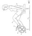
- FIG. 1is a side view of an attachable rotary range of motion exercise and rehabilitation apparatus providing selective adjustment of the range of motion of a user's extremities;
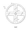
- FIG. 2is a perspective view of a first side of a flywheel of the apparatus
- FIG. 3Ais a section view of the flywheel showing an adjustment member received by the channel and the locking pin engaged;
- FIG. 3Bis a section view of the flywheel showing an adjustment member received by the channel and the locking pin retracted;
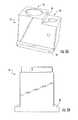
- FIG. 4is a side view showing a second side of the flywheel
- FIG. 5Ais a perspective view of the adjustment member
- FIG. 5Bis a side view of the adjustment member
- FIG. 5Cis a perspective view of the adjustment member engaged with a release mechanism
- FIG. 6is a perspective view showing a user pulling on the release mechanism to move the locking pin to its retracted position
- FIG. 7is a perspective view showing normal motion for the user where the pedals are positioned 180 degrees from each other on either side of the flywheel;
- FIG. 8is a perspective view showing normal motion for the user wherein the flywheel is separated into two separate members;
- FIG. 9is a perspective view showing an embodiment where the apparatus is portable.
- FIG. 10is a perspective view showing an exemplary position for a sit-to-stand range of motion session where the pedals are positioned 0 degrees from each other on either side of the flywheel.
- the present inventionrelates to a rotary range of motion exercise and rehabilitation apparatus which provides selective adjustment of the lever(s) 12 a , 12 b .
- the levers 12 a , 12 bmay be handles for rehabilitating arms or pedals for rehabilitating legs 17 .
- the lever(s) 12 a , 12 bare operatively slidable within a channel 18 on a flywheel 14 between a first radius and a second radius, thereby affecting the range of motion of a user's extremities, including either arms or legs 17 , actively, assisted-actively, or passively engaging in or participating in a cycling action.
- the apparatusmay be retrofit onto an existing cycle machine.
- Various embodimentsprovide an apparatus having selective adjustment of the range of motion of a user's extremities, including either arms or legs 17 , actively, assisted-actively, or passively engaging in a cycling action.
- One embodiment of the present inventionprovides an apparatus having selective adjustment of the range of motion of a user's extremities, including either arms or legs 17 , actively engaging in or passively participating in a cycling action.
- FIG. 1shows an exemplary rotary exercise and rehabilitation apparatus providing for the selection of a range of motion for a user's arms or legs 17 .
- the rotary rehabilitation apparatusis shown incorporated in a cycle-type exercise machine having a support 13 with a flywheel 14 rotatably mounted on one end and a seat 11 positioned at a distance from the support 13 .
- the personcan sit in the seat 11 , place their feet 19 on the pedals/levers 12 a and 12 b and impart a pushing force thereto with their legs 17 to rotate the flywheel 14 around an axis extending in the horizontal plane.
- FIG. 2shows more detail of the flywheel 14 .
- the flywheel 14comprises a circular disk having a perimeter edge and opposing first and second sides, each side having a generally planar surface. In other embodiments, the flywheel 14 may be oval, square, or any other suitable shape. Each of the planer surfaces is adapted to combine with a lever 12 a , 12 b .
- the first and second sides of the flywheel 14are combined to form one unitary flywheel 14 (see FIGS. 3A, 3B , and 10 ). In other embodiments the first and second sides of the flywheel 14 are separately combined with a portion of the apparatus (see FIGS.
- the flywheel 14may be combined with an existing cycle machine by any suitable means.
- the flywheel 14includes an opening 15 near the center adapted to receive a shaft from the existing cycle machine.
- the shaft from the existing machinemay be the shaft which is normally combined with the crank shaft of the pedal. Removing the existing pedal exposes the crank shaft and allows the flywheel 14 to be combined with the shaft so that rotation of the flywheel 14 causes rotation of the shaft.
- the flywheel 14includes one or more channels 18 adapted to receive an adjustment member 24 which is adapted to slide and remain within the channel 18 similar to a sliding dovetail.
- the levers 12 a , 12 bare combined with the adjustment member 24 so that movement of the adjustment member 24 within the channel 18 also changes the position of the levers 12 a , 12 b along the radius of the flywheel 14 .
- the flywheel 14further comprises openings 16 adapted to receive a locking pin 22 which secures the attachment member 24 at a particular location.
- the locking pin 22has a locked position and a retracted position.
- the locking pin 22is biased in its locked position by a spring or any other suitable means.
- the locking pin 22is combined with a release mechanism 20 such as a handle so that movement of the release mechanism 20 moves the locking pin 22 .
- the release mechanism 20may be combined with the attachment member 24 and/or the lever 12 a , 12 b by any suitable means, including being slidably combined with the shaft of the lever 12 a , 12 b .
- the locking pin 22extends through an opening 28 in the locking member 24 and into an opening 16 in the flywheel in its locked position to secure the locking member 24 at a particular location. As shown in FIGS. 3A and 3B and explained below in more detail, retracting the release mechanism 20 causes the locking pin 22 to move to its retracted position out of the opening 16 in the flywheel thereby allowing the locking member 22 to move within the channel 18 .
- This configurationallows a patient or a therapist to adjust the lever 12 a , 12 b quickly and secure the lever 12 a , 12 b into a new position without the need to remove/unstrap the patients extremity from the lever 12 a , 12 b or any medical device attached to the lever 12 a , 12 b such as, for example an immobilization boot.
- other slidable and securing mechanismscan be used in place of the channel 18 and openings 16 .
- a channelcomprising dual saw-tooth edges with a reciprocal saw-tooth securing mechanism can be used to provide more granular adjustments of the lever 12 a , 12 b .
- the example providedis not meant to be limiting and other sliding and securing devices are contemplated.
- the flywheel 14has four channels 18 on the first side of the flywheel 14 arranged in quadrants 90 degrees to one another. Each channel 18 begins near the center of the flywheel 14 and extends toward the outer edge. Any other suitable channel 18 configuration may also be used.
- the adjustment member 24is combined with the flywheel 14 to allow for adjustment along the flywheel 14 radius towards or away from the center point 15 by sliding the adjustment member 24 in a first channel 18 .
- the position of the levers 12 a , 12 bis also adjustable concentrically on the flywheel 14 around the center point 15 by removing the adjustment member 24 from the first channel 18 and inserting the adjustment member 24 in one of the other channels 18 .
- the concentric adjustmentallows the levers 12 a , 12 b to be at an offset angle relative to each other about the flywheel 14 axis of rotation at 0, 90, 180 or 270 degrees.
- FIG. 7shows the levers 12 a , 12 b positioned at a 180 degree angle.
- FIG. 10shows the levers 12 a , 12 b positioned at a zero degree angle so that they are mirror images of each other on either side of the flywheel 14 .
- Other angular offsetsmay be obtained by using other channel configurations in the flywheel 14 . Further, other angular offsets may be obtained by combining the flywheel 14 first side to the cycle at a position that is offset from the flywheel 14 second side. In other words, an angular offset can be obtained if the channels 18 in the flywheel 14 first side are not aligned with the channels 18 on the flywheel 14 second side even if each side of the flywheel 14 only has one channel 18 .
- the combination of the opening 16 diameter and the size of the spring-loaded locking pin 22 releasemust meet medical device requirements to hold a minimum of 730 lbs (331 Kg) of patient weight in some embodiments.
- the apparatuscan be changed on any device to a different apparatus that can release mechanism greater weight requirement without purchasing an entire new machine.
- the spring-loaded locking pin 22 releaseallows the adjustment member's 24 position to be changed quickly without moving the injured extremity from the apparatus, producing faster and safer movement of the limb towards the goals of improved range of motion and function.
- FIGS. 3A and 3Bshow a section view of an exemplary flywheel 14 having a channel 18 in the first side and the second side.
- the channel 18or comparable mechanism, is designed to keep the adjustment member 24 secured to the flywheel 14 (within the channel 18 ) even as the position of the levers 12 a , 12 b is adjusted.
- Each channel 18has at least one channel opening 18 a , 18 b for receiving the adjustment member 24 .
- the channel opening 18 a , 18 bhas a diameter large enough to allow the flange 30 of the adjustment member 24 to be inserted into and removed from the channel 18 .
- the embodiment shown in FIG. 2has two channel openings 18 a , 18 b , one on each end of the channel 18 . Once inserted into a channel 18 , the adjustment member 24 cannot be removed from the flywheel 14 by exerting a force perpendicular to the length of the channel 18 because the slot along the top edge 23 is narrower than the adjustment member's 24 flange 30 .
- the channel 18has a tapered wall to help secure the adjustment member 24 in the channel 18 .
- the channel 18has first width that is wider than a second width. The first width is farther from the top edge 23 of the channel 18 than the second width so that the channel 18 becomes narrower toward the top edge 23 . This creates a lip or flange near the channel's 18 top edge 23 .
- the adjustment member 24includes a flange 30 which is wider than the second width of the channel 18 but not wider than the first width of the channel 18 . This allows the adjustment member 24 to slide within the channel 18 , but not be removed through the slot along the channel's 18 top edge 23 by applying force in the direction of the arrows shown in FIG. 3B .
- the channel 18includes a cambered edge that is used to secure the adjustment member 24 to the flywheel 14 .
- FIG. 4shows an embodiment where the second side of the flywheel 14 does not have a channel 18 .
- This embodimentallows the flywheel 14 to be easily retrofitted onto any cycle ergometer as shown, for example, in FIG. 8 .
- the flywheel 14 first side and the flywheel 14 second sidemay be two separate members, each having a first side as shown in FIG. 2 and a second side as shown in FIG. 4 .
- Each flywheel 14is combined with one side of a cycle device.
- the second sideFIG. 4
- the second sideincludes a plurality of openings 21 adapted to combine with a lever 12 b but does not include a channel 18 .
- the openings 21are positioned to be generally a mirror image of the openings 16 in the first side of the flywheel 14 to allow for proper alignment of the levers 12 a , 12 b .
- the lever 12 b extending from the second side of the flywheel 14may also be combined with the center point 15 of the second side of the flywheel 14 by a crank as described in U.S. Pat. No. 7,226,394 (Johnson).
- FIGS. 5A and 5Bshow an exemplary adjustment member 24 having one or more ridges or flanges 30 adapted to be received into the channel 18 beneath the slot/edge 23 of the channel 18 .
- a first opening 26is adapted to combine with a lever 12 a , 12 b and/or release mechanism 20 by any suitable means. In one embodiment the first opening 26 is threaded to allow the threaded shaft of a lever 12 a , 12 b to be screwed into the opening 26 .
- the adjustment member 24 on one side of the flywheel 14may be reverse threaded as is know in the cycling industry.
- a second opening 28 in the adjustment member 24is adapted to receive at least a portion of the locking pin 22 .
- the locking pin 22is combined with the release mechanism 20 and extends through the second opening 28 and into the openings 16 in the flywheel 14 in its locked position.
- FIG. 6shows a user moving the release mechanism 20 in the direction of the arrows in FIG. 3B to retract the locking pin 22 from the opening 16 in the flywheel 14 and allow movement of the adjustment member 24 within the channel 18 .
- the release mechanism 20While the release mechanism 20 is in the raised position the lever 12 a /adjustment member 24 can be adjusted along the radius of the flywheel 14 without removing the patient's extremity from the lever 12 a , 12 b . This saves time and effort as the release mechanism 20 is configured to reduce the amount of force or leverage that is required to activate the securing pin 22 .
- a stepped ridgeis located between the first opening 26 and the second opening 28 to provide a surface around the first opening 26 that is higher than a surface around the second opening 28 .
- the stepped ridgehelps secure the spring-loaded pin 22 from moving while the apparatus is in use. It is an added safety measure to insure that the adjustment member 24 stays in the set position without slipping.
- the release mechanism 20is biased toward the adjustment member 24 so one of its surfaces engages the lower surface around the second opening 28 and another one of its surfaces engages the stepped vertical surface 29 when the pin 22 is in its locked position.
- the vertical surface 29helps keep the release mechanism 20 from moving or spinning to a position where it could be accidently kicked or released by the user.
- the adjustment member 24is made of any material that can pass the industry standard ISO 20957-1:2005 weight test when inserted into the channel 18 on the flywheel 14 .
- the adjustment member 24can take a minimum of 730 lbs (331 Kg).
- the adjustment member 24 and the corresponding channel 18can be widened or made thicker as needed to accommodate heavier patients or more rigorous training.
- the flywheel 14can be designed to have a relatively large or small moment of inertia.
- a large moment of inertia flywheel 14requires more peddling force to accelerate the same to a given speed, but also causes the flywheel 14 to better resist changes in speed, resulting in smoother “steady-state” cycling, which may be preferred in certain rehabilitation exercises.
- the higher moment of inertiais created by making the flywheel 14 heavier and/or moving more of the flywheel weight out to the circumferential ring 30 .
- the overall resistance to turning of the flywheel 14may be controlled to increase the amount of work a user must perform in peddling, as those of skill in the art appreciate with respect to known cycle-type exercise machines.
- frictional resistancemay be incorporated in to the design to require a certain amount of force to overcome the static and dynamic friction to turn the flywheel 14 .
- a frictional surface(not shown), for example, a brake, may selectively engage the flywheel 14 to create static and dynamic friction.
- portions of the apparatusare made from any material capable of passing industry standard weight tests described in ISO 20957-1:2005 for stationary training equipment.
- the apparatuscan withstand at least a minimum of 1.82 times 401 lbs. (182 kg) or 730 lbs (331 Kg) of force.
- the materialmay be aluminum.
- a central opening 15 in the diskcan be sized to be retrofitted onto any cycle ergometers device converting the cycle ergometers into a therapeutic range of motion device.
- Thisis a vast improvement over the prior art, where many devices are single purpose and are relatively expensive.
- the claimed apparatusprovides greater flexibility and cost savings to patients, hospitals and other therapy locations. It also allows for portable devices to be created that can be taken to the patient's home by a therapist for in home therapy or purchased by the patient at a much reduced cost than was available in the prior art. Additionally, the apparatus can be fully cleaned when removed from the cycle ergometer, which can be a requirement not attainable with current single purpose devices.
- a quick release mechanismcan also be attached to the flywheel 14 to attach and remove the apparatus from a third-party cycle ergometer. This allows the apparatus to be portable between cycle ergometers at different locations or even at the same location depending upon a physician prescribed routine and the needs of the patient.
- the first and second side of the flywheel 14includes position indicators marking the channels 18 and openings 16 , 21 .
- the indicators on each flywheel 14can be recorded in a therapy or training log for use by the physician or the therapist. The indicators can also be used during training to measure progress as the adjustment member 24 is moved throughout the session.
- each lever 12 a , 12 bis located near opposing outer edges (180 degrees from each other) on either side of the flywheel 14 .
- An uninjured, or fully recovered, patientcan operate the apparatus in a normal cyclical motion. This is the final goal of most therapies. Once the patient can successfully perform this motion, additional resistance can be introduced through the apparatus to begin strength training of the patient.
- FIG. 8there is shown an image of a patient using the apparatus wherein two separate flywheel 14 components are used, one on each side of the device.
- the apparatushas been attached to an existing third party cycle ergometer.
- the cycle ergometerstill maintains all of its original capabilities, but it has been enhanced with the addition of the apparatus.
- the patient's affected extremity strapped to the pedal adapter in a medical deviceBecause of this injury to the patient, removing the affected extremity from the medical device and resetting the pedal adapter would be a time consuming and wasteful effort that is eliminated with the apparatus as described above.
- the patientreceived the maximum amount of therapy in the time allotted which will speed the patient's recovery, freeing needed resources for other patients.
- FIG. 9shows a portable unit with a dual apparatus setup that can combine range of motion and resistance in a small portable package.
- This embodimentdoes not include a seat 11 or a support 13 .
- the costis significantly lower for the portable cycle ergometer. Hospitals can have therapy begun much earlier in the patient's room, or it can be used to prepare the affected extremity prior to surgery. Traveling physical therapists can easily take the portable cycle ergometer to a patient's residence to continue therapy after being released from the hospital. Patients with long term needs can afford to purchase the portable cycle ergometer due to the much lower price than a standard, bulky cycle ergometer.
- FIG. 10shows a patient using the device with both levers 12 a , 12 b positioned at the same location (zero degrees from each other) on opposite sides of the flywheel 14 .
- both legsare pushing or pulling at the same time to simulate a sit-to-stand range of motion session.
- additional resistancecan be added to the apparatus, as will be understood by those with skill in the art, so that the patient will be able to get up from a chair or sitting position lifting their upper body weight.
- Inpatient or outpatient use of an apparatuswould be necessary, in patients young or old, with work injuries to arthritis to neurologic abnormalities, burns, morbid obesity, etc. for continued rehabilitation following the initiation of rehab from the Orthopedic, Surgical, Medical, Emergency, or other clinical settings upon discharge.
- a hospital or other facility that can use the device across many diagnoses and clinical settingsis a significant budgetary factor in determining cost effectiveness. Additionally, male or female participants, with varying hand sizes and levels of strength, varying levels of knowledge and interventional skill, or manipulative abilities to due arthritis or age, etc. must be able to easily recognize how to use the apparatus in a clinical or home setting, or it will not be utilized.
- the present inventionovercomes all the limitations of the prior art in a cost effective manner.
Landscapes
- Health & Medical Sciences (AREA)
- General Health & Medical Sciences (AREA)
- Physical Education & Sports Medicine (AREA)
- Life Sciences & Earth Sciences (AREA)
- Vascular Medicine (AREA)
- Cardiology (AREA)
- Orthopedic Medicine & Surgery (AREA)
- Animal Behavior & Ethology (AREA)
- Public Health (AREA)
- Veterinary Medicine (AREA)
- Rehabilitation Therapy (AREA)
- Pain & Pain Management (AREA)
- Epidemiology (AREA)
- Biophysics (AREA)
- Rehabilitation Tools (AREA)
Abstract
Description
Claims (19)
Priority Applications (1)
| Application Number | Priority Date | Filing Date | Title |
|---|---|---|---|
| US15/331,267US10569122B2 (en) | 2015-10-21 | 2016-10-21 | Attachable rotary range of motion rehabilitation apparatus |
Applications Claiming Priority (2)
| Application Number | Priority Date | Filing Date | Title |
|---|---|---|---|
| US201562244190P | 2015-10-21 | 2015-10-21 | |
| US15/331,267US10569122B2 (en) | 2015-10-21 | 2016-10-21 | Attachable rotary range of motion rehabilitation apparatus |
Publications (2)
| Publication Number | Publication Date |
|---|---|
| US20170113092A1 US20170113092A1 (en) | 2017-04-27 |
| US10569122B2true US10569122B2 (en) | 2020-02-25 |
Family
ID=58557901
Family Applications (1)
| Application Number | Title | Priority Date | Filing Date |
|---|---|---|---|
| US15/331,267ActiveUS10569122B2 (en) | 2015-10-21 | 2016-10-21 | Attachable rotary range of motion rehabilitation apparatus |
Country Status (2)
| Country | Link |
|---|---|
| US (1) | US10569122B2 (en) |
| WO (1) | WO2017070517A1 (en) |
Cited By (62)
| Publication number | Priority date | Publication date | Assignee | Title |
|---|---|---|---|---|
| US11260256B2 (en)* | 2020-06-16 | 2022-03-01 | Great Fitness Industrial Co., Ltd. | Symmetric upright rotating disc exercise machine |
| US11410768B2 (en) | 2019-10-03 | 2022-08-09 | Rom Technologies, Inc. | Method and system for implementing dynamic treatment environments based on patient information |
| US11445985B2 (en) | 2019-10-03 | 2022-09-20 | Rom Technologies, Inc. | Augmented reality placement of goniometer or other sensors |
| US11471729B2 (en) | 2019-03-11 | 2022-10-18 | Rom Technologies, Inc. | System, method and apparatus for a rehabilitation machine with a simulated flywheel |
| US11508482B2 (en) | 2019-10-03 | 2022-11-22 | Rom Technologies, Inc. | Systems and methods for remotely-enabled identification of a user infection |
| US11515021B2 (en) | 2019-10-03 | 2022-11-29 | Rom Technologies, Inc. | Method and system to analytically optimize telehealth practice-based billing processes and revenue while enabling regulatory compliance |
| US11515028B2 (en) | 2019-10-03 | 2022-11-29 | Rom Technologies, Inc. | Method and system for using artificial intelligence and machine learning to create optimal treatment plans based on monetary value amount generated and/or patient outcome |
| US11596829B2 (en) | 2019-03-11 | 2023-03-07 | Rom Technologies, Inc. | Control system for a rehabilitation and exercise electromechanical device |
| US11701548B2 (en) | 2019-10-07 | 2023-07-18 | Rom Technologies, Inc. | Computer-implemented questionnaire for orthopedic treatment |
| US11752391B2 (en) | 2019-03-11 | 2023-09-12 | Rom Technologies, Inc. | System, method and apparatus for adjustable pedal crank |
| US11756666B2 (en) | 2019-10-03 | 2023-09-12 | Rom Technologies, Inc. | Systems and methods to enable communication detection between devices and performance of a preventative action |
| US20230347205A1 (en)* | 2022-04-28 | 2023-11-02 | Toyota Jidosha Kabushiki Kaisha | Pedal support structure and pedal support system |
| US11830601B2 (en) | 2019-10-03 | 2023-11-28 | Rom Technologies, Inc. | System and method for facilitating cardiac rehabilitation among eligible users |
| US11826613B2 (en) | 2019-10-21 | 2023-11-28 | Rom Technologies, Inc. | Persuasive motivation for orthopedic treatment |
| US11887717B2 (en) | 2019-10-03 | 2024-01-30 | Rom Technologies, Inc. | System and method for using AI, machine learning and telemedicine to perform pulmonary rehabilitation via an electromechanical machine |
| US11915815B2 (en) | 2019-10-03 | 2024-02-27 | Rom Technologies, Inc. | System and method for using artificial intelligence and machine learning and generic risk factors to improve cardiovascular health such that the need for additional cardiac interventions is mitigated |
| US11915816B2 (en) | 2019-10-03 | 2024-02-27 | Rom Technologies, Inc. | Systems and methods of using artificial intelligence and machine learning in a telemedical environment to predict user disease states |
| US11923065B2 (en) | 2019-10-03 | 2024-03-05 | Rom Technologies, Inc. | Systems and methods for using artificial intelligence and machine learning to detect abnormal heart rhythms of a user performing a treatment plan with an electromechanical machine |
| US11923057B2 (en) | 2019-10-03 | 2024-03-05 | Rom Technologies, Inc. | Method and system using artificial intelligence to monitor user characteristics during a telemedicine session |
| US11942205B2 (en) | 2019-10-03 | 2024-03-26 | Rom Technologies, Inc. | Method and system for using virtual avatars associated with medical professionals during exercise sessions |
| US11955222B2 (en) | 2019-10-03 | 2024-04-09 | Rom Technologies, Inc. | System and method for determining, based on advanced metrics of actual performance of an electromechanical machine, medical procedure eligibility in order to ascertain survivability rates and measures of quality-of-life criteria |
| US11955221B2 (en) | 2019-10-03 | 2024-04-09 | Rom Technologies, Inc. | System and method for using AI/ML to generate treatment plans to stimulate preferred angiogenesis |
| US11955223B2 (en) | 2019-10-03 | 2024-04-09 | Rom Technologies, Inc. | System and method for using artificial intelligence and machine learning to provide an enhanced user interface presenting data pertaining to cardiac health, bariatric health, pulmonary health, and/or cardio-oncologic health for the purpose of performing preventative actions |
| US11950861B2 (en) | 2019-10-03 | 2024-04-09 | Rom Technologies, Inc. | Telemedicine for orthopedic treatment |
| US11955220B2 (en) | 2019-10-03 | 2024-04-09 | Rom Technologies, Inc. | System and method for using AI/ML and telemedicine for invasive surgical treatment to determine a cardiac treatment plan that uses an electromechanical machine |
| US11955218B2 (en) | 2019-10-03 | 2024-04-09 | Rom Technologies, Inc. | System and method for use of telemedicine-enabled rehabilitative hardware and for encouraging rehabilitative compliance through patient-based virtual shared sessions with patient-enabled mutual encouragement across simulated social networks |
| US11961603B2 (en) | 2019-10-03 | 2024-04-16 | Rom Technologies, Inc. | System and method for using AI ML and telemedicine to perform bariatric rehabilitation via an electromechanical machine |
| US12020799B2 (en) | 2019-10-03 | 2024-06-25 | Rom Technologies, Inc. | Rowing machines, systems including rowing machines, and methods for using rowing machines to perform treatment plans for rehabilitation |
| US12020800B2 (en) | 2019-10-03 | 2024-06-25 | Rom Technologies, Inc. | System and method for using AI/ML and telemedicine to integrate rehabilitation for a plurality of comorbid conditions |
| US12057237B2 (en) | 2020-04-23 | 2024-08-06 | Rom Technologies, Inc. | Method and system for describing and recommending optimal treatment plans in adaptive telemedical or other contexts |
| US12062425B2 (en) | 2019-10-03 | 2024-08-13 | Rom Technologies, Inc. | System and method for implementing a cardiac rehabilitation protocol by using artificial intelligence and standardized measurements |
| US12087426B2 (en) | 2019-10-03 | 2024-09-10 | Rom Technologies, Inc. | Systems and methods for using AI ML to predict, based on data analytics or big data, an optimal number or range of rehabilitation sessions for a user |
| US12096997B2 (en) | 2019-10-03 | 2024-09-24 | Rom Technologies, Inc. | Method and system for treating patients via telemedicine using sensor data from rehabilitation or exercise equipment |
| US12100499B2 (en) | 2020-08-06 | 2024-09-24 | Rom Technologies, Inc. | Method and system for using artificial intelligence and machine learning to create optimal treatment plans based on monetary value amount generated and/or patient outcome |
| US12165768B2 (en) | 2019-10-03 | 2024-12-10 | Rom Technologies, Inc. | Method and system for use of telemedicine-enabled rehabilitative equipment for prediction of secondary disease |
| US12176091B2 (en) | 2019-10-03 | 2024-12-24 | Rom Technologies, Inc. | Systems and methods for using elliptical machine to perform cardiovascular rehabilitation |
| US12176089B2 (en) | 2019-10-03 | 2024-12-24 | Rom Technologies, Inc. | System and method for using AI ML and telemedicine for cardio-oncologic rehabilitation via an electromechanical machine |
| US12183447B2 (en) | 2019-10-03 | 2024-12-31 | Rom Technologies, Inc. | Method and system for creating an immersive enhanced reality-driven exercise experience for a user |
| US12191018B2 (en) | 2019-10-03 | 2025-01-07 | Rom Technologies, Inc. | System and method for using artificial intelligence in telemedicine-enabled hardware to optimize rehabilitative routines capable of enabling remote rehabilitative compliance |
| US12191021B2 (en) | 2019-10-03 | 2025-01-07 | Rom Technologies, Inc. | System and method for use of telemedicine-enabled rehabilitative hardware and for encouragement of rehabilitative compliance through patient-based virtual shared sessions |
| US12217865B2 (en) | 2019-10-03 | 2025-02-04 | Rom Technologies, Inc. | Method and system for enabling physician-smart virtual conference rooms for use in a telehealth context |
| US12224052B2 (en) | 2019-10-03 | 2025-02-11 | Rom Technologies, Inc. | System and method for using AI, machine learning and telemedicine for long-term care via an electromechanical machine |
| US12220201B2 (en) | 2019-10-03 | 2025-02-11 | Rom Technologies, Inc. | Remote examination through augmented reality |
| US12230381B2 (en) | 2019-10-03 | 2025-02-18 | Rom Technologies, Inc. | System and method for an enhanced healthcare professional user interface displaying measurement information for a plurality of users |
| US12230382B2 (en) | 2019-10-03 | 2025-02-18 | Rom Technologies, Inc. | Systems and methods for using artificial intelligence and machine learning to predict a probability of an undesired medical event occurring during a treatment plan |
| US12249410B2 (en) | 2019-10-03 | 2025-03-11 | Rom Technologies, Inc. | System and method for use of treatment device to reduce pain medication dependency |
| US12246222B2 (en) | 2019-10-03 | 2025-03-11 | Rom Technologies, Inc. | Method and system for using artificial intelligence to assign patients to cohorts and dynamically controlling a treatment apparatus based on the assignment during an adaptive telemedical session |
| US12283356B2 (en) | 2019-10-03 | 2025-04-22 | Rom Technologies, Inc. | System and method for processing medical claims using biometric signatures |
| US12285654B2 (en) | 2019-05-10 | 2025-04-29 | Rom Technologies, Inc. | Method and system for using artificial intelligence to interact with a user of an exercise device during an exercise session |
| US12301663B2 (en) | 2019-10-03 | 2025-05-13 | Rom Technologies, Inc. | System and method for transmitting data and ordering asynchronous data |
| US12324961B2 (en) | 2019-05-10 | 2025-06-10 | Rom Technologies, Inc. | Method and system for using artificial intelligence to present a user interface representing a user's progress in various domains |
| US12327623B2 (en) | 2019-10-03 | 2025-06-10 | Rom Technologies, Inc. | System and method for processing medical claims |
| US12347558B2 (en) | 2019-10-03 | 2025-07-01 | Rom Technologies, Inc. | Method and system for using artificial intelligence and machine learning to provide recommendations to a healthcare provider in or near real-time during a telemedicine session |
| US12347543B2 (en) | 2019-10-03 | 2025-07-01 | Rom Technologies, Inc. | Systems and methods for using artificial intelligence to implement a cardio protocol via a relay-based system |
| US12357195B2 (en) | 2020-06-26 | 2025-07-15 | Rom Technologies, Inc. | System, method and apparatus for anchoring an electronic device and measuring a joint angle |
| US12380984B2 (en) | 2019-10-03 | 2025-08-05 | Rom Technologies, Inc. | Systems and methods for using artificial intelligence and machine learning to generate treatment plans having dynamically tailored cardiac protocols for users to manage a state of an electromechanical machine |
| US12402804B2 (en) | 2019-09-17 | 2025-09-02 | Rom Technologies, Inc. | Wearable device for coupling to a user, and measuring and monitoring user activity |
| US12424319B2 (en) | 2019-11-06 | 2025-09-23 | Rom Technologies, Inc. | System for remote treatment utilizing privacy controls |
| US12420145B2 (en) | 2019-10-03 | 2025-09-23 | Rom Technologies, Inc. | Systems and methods of using artificial intelligence and machine learning for generating alignment plans to align a user with an imaging sensor during a treatment session |
| US12420143B1 (en) | 2019-10-03 | 2025-09-23 | Rom Technologies, Inc. | System and method for enabling residentially-based cardiac rehabilitation by using an electromechanical machine and educational content to mitigate risk factors and optimize user behavior |
| US12427376B2 (en) | 2019-10-03 | 2025-09-30 | Rom Technologies, Inc. | Systems and methods for an artificial intelligence engine to optimize a peak performance |
| US12440725B2 (en)* | 2022-04-28 | 2025-10-14 | Toyota Jidosha Kabushiki Kaisha | Pedal support structure and pedal support system |
Families Citing this family (19)
| Publication number | Priority date | Publication date | Assignee | Title |
|---|---|---|---|---|
| US10569122B2 (en)* | 2015-10-21 | 2020-02-25 | Hurford Global, Llc | Attachable rotary range of motion rehabilitation apparatus |
| WO2018049299A1 (en) | 2016-09-12 | 2018-03-15 | ROM3 Rehab LLC | Adjustable rehabilitation and exercise device |
| US10646746B1 (en) | 2016-09-12 | 2020-05-12 | Rom Technologies, Inc. | Adjustable rehabilitation and exercise device |
| US10507355B2 (en)* | 2017-03-17 | 2019-12-17 | Mindbridge Innovations, Llc | Stationary cycling pedal crank having an adjustable length |
| FR3067324A1 (en)* | 2017-06-12 | 2018-12-14 | Pierre Giovine | DEVICE FOR DRIVING BICYCLE CRANKSETS WITH TWO ORTHOGONAL RAILS BETWEEN THEM, PEDAL SLIDING SHUTTLE CARRIERS |
| CN108042976A (en)* | 2018-01-26 | 2018-05-18 | 沈阳体育学院 | Tai Ji lower limb stability auxiliary apparatus |
| CN109044721B (en)* | 2018-06-27 | 2020-09-01 | 郭立宏 | Taste shank joint exercise rehabilitation device |
| CN109820694B (en)* | 2019-03-28 | 2021-03-30 | 温州市人民医院 | Leg exercising device |
| US11433276B2 (en)* | 2019-05-10 | 2022-09-06 | Rehab2Fit Technologies, Inc. | Method and system for using artificial intelligence to independently adjust resistance of pedals based on leg strength |
| US11957960B2 (en)* | 2019-05-10 | 2024-04-16 | Rehab2Fit Technologies Inc. | Method and system for using artificial intelligence to adjust pedal resistance |
| US12102878B2 (en) | 2019-05-10 | 2024-10-01 | Rehab2Fit Technologies, Inc. | Method and system for using artificial intelligence to determine a user's progress during interval training |
| CN110074942A (en)* | 2019-05-27 | 2019-08-02 | 北京理工华汇智能科技有限公司 | Device for healing and training and rehabilitation wheelchair with Telescopic |
| CN110251381B (en)* | 2019-06-25 | 2021-09-14 | 重庆医科大学附属永川医院 | Pregnant woman postpartum care rehabilitation device |
| US10742530B1 (en) | 2019-08-05 | 2020-08-11 | Extrahop Networks, Inc. | Correlating network traffic that crosses opaque endpoints |
| USD928635S1 (en) | 2019-09-18 | 2021-08-24 | Rom Technologies, Inc. | Goniometer |
| US11325005B2 (en) | 2019-10-03 | 2022-05-10 | Rom Technologies, Inc. | Systems and methods for using machine learning to control an electromechanical device used for prehabilitation, rehabilitation, and/or exercise |
| US20210134458A1 (en) | 2019-10-03 | 2021-05-06 | Rom Technologies, Inc. | System and method to enable remote adjustment of a device during a telemedicine session |
| USD907143S1 (en) | 2019-12-17 | 2021-01-05 | Rom Technologies, Inc. | Rehabilitation device |
| US11925834B2 (en)* | 2020-04-15 | 2024-03-12 | Tana Burke | Mobile cycling apparatus |
Citations (33)
| Publication number | Priority date | Publication date | Assignee | Title |
|---|---|---|---|---|
| US610157A (en) | 1898-08-30 | Half to william h | ||
| US4446753A (en) | 1981-09-24 | 1984-05-08 | Shimano Industrial Company Limited | Adjustable length crank arm for a bicycle |
| US4509742A (en)* | 1983-06-06 | 1985-04-09 | Cones Charles F | Exercise bicycle |
| DE8519150U1 (en) | 1985-07-02 | 1985-10-24 | Hupp, Johannes, 2300 Klausdorf | Foot pedal crank assembly |
| US4606241A (en) | 1983-04-29 | 1986-08-19 | Verner Fredriksson | Adjustable crank assembly |
| US4611807A (en)* | 1984-02-16 | 1986-09-16 | Castillo David D | Exercise apparatus having a pair of spaced apart rotating discs |
| DE3732905A1 (en) | 1986-09-30 | 1988-07-28 | Anton Reck | Crank arrangement having pedals, in particular for training apparatuses |
| US4850245A (en) | 1987-06-19 | 1989-07-25 | Feamster Nicholas G | Bicycle crank and pedal structure |
| US4858942A (en) | 1988-08-12 | 1989-08-22 | Otto Rodriguez | Manually driven bicycle |
| US5161430A (en) | 1990-05-18 | 1992-11-10 | Febey Richard W | Pedal stroke range adjusting device |
| USD342299S (en) | 1991-07-12 | 1993-12-14 | Precor Incorporated | Recumbent exercise cycle |
| US5274853A (en) | 1991-11-12 | 1994-01-04 | Millican Robert D | Adjustable shirt collar |
| US5316532A (en)* | 1993-08-12 | 1994-05-31 | Butler Brian R | Aquatic exercise and rehabilitation device |
| US5338272A (en) | 1993-12-03 | 1994-08-16 | Sweeney Iii Edward C | Exercise machine |
| US5361649A (en) | 1992-07-20 | 1994-11-08 | High Sierra Cycle Center | Bicycle crank and pedal assembly |
| US5458022A (en) | 1993-11-15 | 1995-10-17 | Mattfeld; Raymond | Bicycle pedal range adjusting device |
| US5580338A (en) | 1995-03-06 | 1996-12-03 | Scelta; Anthony | Portable, upper body, exercise machine |
| US5685804A (en)* | 1995-12-07 | 1997-11-11 | Precor Incorporated | Stationary exercise device |
| US5860941A (en) | 1995-11-14 | 1999-01-19 | Orthologic Corp. | Active/passive device for rehabilitation of upper and lower extremities |
| US6053847A (en) | 1997-05-05 | 2000-04-25 | Stearns; Kenneth W. | Elliptical exercise method and apparatus |
| EP1034817A1 (en) | 1999-03-09 | 2000-09-13 | Paul John Butterworth | Exercise and rehabilitation equipment |
| US6155958A (en) | 1992-10-30 | 2000-12-05 | Madd Dog Athletics, Inc. | Stationary exercise bicycle having a rigid frame |
| DE19947926A1 (en) | 1999-10-06 | 2001-04-12 | Medica Medizintechnik Gmbh | Training device for movement therapy, especially to move arm or leg of bed-ridden person; has adjustable handles or pedals connected to rotating support disc driven by peripherally engaging motor |
| US6253638B1 (en) | 1999-06-10 | 2001-07-03 | David Bermudez | Bicycle sprocket crank |
| US6543309B2 (en) | 1996-09-03 | 2003-04-08 | Jonathan R. Heim | Clipless bicycle pedal |
| US6865969B2 (en) | 2003-03-28 | 2005-03-15 | Kerry Peters Stevens | Adjustable pedal for exercise devices |
| US20050085353A1 (en) | 2003-10-16 | 2005-04-21 | Johnson Kenneth W. | Rotary rehabilitation apparatus and method |
| US20060019802A1 (en) | 2004-07-26 | 2006-01-26 | Robert Caird | Removable crank arm for exercise cycle |
| US7226394B2 (en) | 2003-10-16 | 2007-06-05 | Johnson Kenneth W | Rotary rehabilitation apparatus and method |
| US20080161166A1 (en) | 2006-12-28 | 2008-07-03 | Chiu Hsiang Lo | Exercise Machine With Adjustable Pedals |
| US20090211395A1 (en) | 2008-02-25 | 2009-08-27 | Mul E Leonard | Adjustable pedal system for exercise bike |
| US9480873B2 (en)* | 2014-11-25 | 2016-11-01 | High Spot Health Technology Co., Ltd. | Adjusting structure of elliptical trainer |
| US20170113092A1 (en)* | 2015-10-21 | 2017-04-27 | Brainchild Medical, Inc. | Attachable Rotary Range of Motion Rehabilitation Apparatus |
- 2016
- 2016-10-21USUS15/331,267patent/US10569122B2/enactiveActive
- 2016-10-21WOPCT/US2016/058187patent/WO2017070517A1/ennot_activeCeased
Patent Citations (35)
| Publication number | Priority date | Publication date | Assignee | Title |
|---|---|---|---|---|
| US610157A (en) | 1898-08-30 | Half to william h | ||
| US4446753A (en) | 1981-09-24 | 1984-05-08 | Shimano Industrial Company Limited | Adjustable length crank arm for a bicycle |
| US4606241A (en) | 1983-04-29 | 1986-08-19 | Verner Fredriksson | Adjustable crank assembly |
| US4509742A (en)* | 1983-06-06 | 1985-04-09 | Cones Charles F | Exercise bicycle |
| US4611807A (en)* | 1984-02-16 | 1986-09-16 | Castillo David D | Exercise apparatus having a pair of spaced apart rotating discs |
| DE8519150U1 (en) | 1985-07-02 | 1985-10-24 | Hupp, Johannes, 2300 Klausdorf | Foot pedal crank assembly |
| DE3732905A1 (en) | 1986-09-30 | 1988-07-28 | Anton Reck | Crank arrangement having pedals, in particular for training apparatuses |
| US4850245A (en) | 1987-06-19 | 1989-07-25 | Feamster Nicholas G | Bicycle crank and pedal structure |
| US4858942A (en) | 1988-08-12 | 1989-08-22 | Otto Rodriguez | Manually driven bicycle |
| US5161430A (en) | 1990-05-18 | 1992-11-10 | Febey Richard W | Pedal stroke range adjusting device |
| USD342299S (en) | 1991-07-12 | 1993-12-14 | Precor Incorporated | Recumbent exercise cycle |
| US5274853A (en) | 1991-11-12 | 1994-01-04 | Millican Robert D | Adjustable shirt collar |
| US5361649A (en) | 1992-07-20 | 1994-11-08 | High Sierra Cycle Center | Bicycle crank and pedal assembly |
| US6155958A (en) | 1992-10-30 | 2000-12-05 | Madd Dog Athletics, Inc. | Stationary exercise bicycle having a rigid frame |
| US5316532A (en)* | 1993-08-12 | 1994-05-31 | Butler Brian R | Aquatic exercise and rehabilitation device |
| US5458022A (en) | 1993-11-15 | 1995-10-17 | Mattfeld; Raymond | Bicycle pedal range adjusting device |
| US5338272A (en) | 1993-12-03 | 1994-08-16 | Sweeney Iii Edward C | Exercise machine |
| US5580338A (en) | 1995-03-06 | 1996-12-03 | Scelta; Anthony | Portable, upper body, exercise machine |
| US5860941A (en) | 1995-11-14 | 1999-01-19 | Orthologic Corp. | Active/passive device for rehabilitation of upper and lower extremities |
| US5685804A (en)* | 1995-12-07 | 1997-11-11 | Precor Incorporated | Stationary exercise device |
| US6543309B2 (en) | 1996-09-03 | 2003-04-08 | Jonathan R. Heim | Clipless bicycle pedal |
| US6053847A (en) | 1997-05-05 | 2000-04-25 | Stearns; Kenneth W. | Elliptical exercise method and apparatus |
| EP1034817A1 (en) | 1999-03-09 | 2000-09-13 | Paul John Butterworth | Exercise and rehabilitation equipment |
| US6589139B1 (en)* | 1999-03-09 | 2003-07-08 | Paul John Butterworth | Exercise and rehabilitation equipment |
| US6253638B1 (en) | 1999-06-10 | 2001-07-03 | David Bermudez | Bicycle sprocket crank |
| DE19947926A1 (en) | 1999-10-06 | 2001-04-12 | Medica Medizintechnik Gmbh | Training device for movement therapy, especially to move arm or leg of bed-ridden person; has adjustable handles or pedals connected to rotating support disc driven by peripherally engaging motor |
| US6865969B2 (en) | 2003-03-28 | 2005-03-15 | Kerry Peters Stevens | Adjustable pedal for exercise devices |
| US20050085353A1 (en) | 2003-10-16 | 2005-04-21 | Johnson Kenneth W. | Rotary rehabilitation apparatus and method |
| US7226394B2 (en) | 2003-10-16 | 2007-06-05 | Johnson Kenneth W | Rotary rehabilitation apparatus and method |
| US7594879B2 (en)* | 2003-10-16 | 2009-09-29 | Brainchild Llc | Rotary rehabilitation apparatus and method |
| US20060019802A1 (en) | 2004-07-26 | 2006-01-26 | Robert Caird | Removable crank arm for exercise cycle |
| US20080161166A1 (en) | 2006-12-28 | 2008-07-03 | Chiu Hsiang Lo | Exercise Machine With Adjustable Pedals |
| US20090211395A1 (en) | 2008-02-25 | 2009-08-27 | Mul E Leonard | Adjustable pedal system for exercise bike |
| US9480873B2 (en)* | 2014-11-25 | 2016-11-01 | High Spot Health Technology Co., Ltd. | Adjusting structure of elliptical trainer |
| US20170113092A1 (en)* | 2015-10-21 | 2017-04-27 | Brainchild Medical, Inc. | Attachable Rotary Range of Motion Rehabilitation Apparatus |
Non-Patent Citations (7)
| Title |
|---|
| "ROM3 Rehab System" uploaded by ROM3 Rehab, Apr. 20, 2015. https://vimeo.com/125438463.* |
| Achieve-Fit for Every Body "Spirit MR100 Rehabilitation Recumbent Bike" (Date Unknown). |
| Achieve—Fit for Every Body "Spirit MR100 Rehabilitation Recumbent Bike" (Date Unknown). |
| PCT/US16/58187 Written Opinion of the International Search Report dated Jan. 23, 2017. |
| SNS Care Co., LTD-User Manual-Apr. 15, 2009. |
| SNS Care Co., LTD—User Manual—Apr. 15, 2009. |
| Sports/Art "Recumbent Cycle C521M" (GoSportsArt.com) (Date Unknown). |
Cited By (81)
| Publication number | Priority date | Publication date | Assignee | Title |
|---|---|---|---|---|
| US12083381B2 (en) | 2019-03-11 | 2024-09-10 | Rom Technologies, Inc. | Bendable sensor device for monitoring joint extension and flexion |
| US11752391B2 (en) | 2019-03-11 | 2023-09-12 | Rom Technologies, Inc. | System, method and apparatus for adjustable pedal crank |
| US12029940B2 (en) | 2019-03-11 | 2024-07-09 | Rom Technologies, Inc. | Single sensor wearable device for monitoring joint extension and flexion |
| US11471729B2 (en) | 2019-03-11 | 2022-10-18 | Rom Technologies, Inc. | System, method and apparatus for a rehabilitation machine with a simulated flywheel |
| US12059591B2 (en) | 2019-03-11 | 2024-08-13 | Rom Technologies, Inc. | Bendable sensor device for monitoring joint extension and flexion |
| US12083380B2 (en) | 2019-03-11 | 2024-09-10 | Rom Technologies, Inc. | Bendable sensor device for monitoring joint extension and flexion |
| US11904202B2 (en) | 2019-03-11 | 2024-02-20 | Rom Technolgies, Inc. | Monitoring joint extension and flexion using a sensor device securable to an upper and lower limb |
| US12226670B2 (en) | 2019-03-11 | 2025-02-18 | Rom Technologies, Inc. | System, method and apparatus for electrically actuated pedal for an exercise or rehabilitation machine |
| US11596829B2 (en) | 2019-03-11 | 2023-03-07 | Rom Technologies, Inc. | Control system for a rehabilitation and exercise electromechanical device |
| US11541274B2 (en) | 2019-03-11 | 2023-01-03 | Rom Technologies, Inc. | System, method and apparatus for electrically actuated pedal for an exercise or rehabilitation machine |
| US12226671B2 (en) | 2019-03-11 | 2025-02-18 | Rom Technologies, Inc. | System, method and apparatus for electrically actuated pedal for an exercise or rehabilitation machine |
| US12186623B2 (en) | 2019-03-11 | 2025-01-07 | Rom Technologies, Inc. | Monitoring joint extension and flexion using a sensor device securable to an upper and lower limb |
| US12285654B2 (en) | 2019-05-10 | 2025-04-29 | Rom Technologies, Inc. | Method and system for using artificial intelligence to interact with a user of an exercise device during an exercise session |
| US12324961B2 (en) | 2019-05-10 | 2025-06-10 | Rom Technologies, Inc. | Method and system for using artificial intelligence to present a user interface representing a user's progress in various domains |
| US12402805B2 (en) | 2019-09-17 | 2025-09-02 | Rom Technologies, Inc. | Wearable device for coupling to a user, and measuring and monitoring user activity |
| US12402804B2 (en) | 2019-09-17 | 2025-09-02 | Rom Technologies, Inc. | Wearable device for coupling to a user, and measuring and monitoring user activity |
| US12154672B2 (en) | 2019-10-03 | 2024-11-26 | Rom Technologies, Inc. | Method and system for implementing dynamic treatment environments based on patient information |
| US12327623B2 (en) | 2019-10-03 | 2025-06-10 | Rom Technologies, Inc. | System and method for processing medical claims |
| US11915816B2 (en) | 2019-10-03 | 2024-02-27 | Rom Technologies, Inc. | Systems and methods of using artificial intelligence and machine learning in a telemedical environment to predict user disease states |
| US11923065B2 (en) | 2019-10-03 | 2024-03-05 | Rom Technologies, Inc. | Systems and methods for using artificial intelligence and machine learning to detect abnormal heart rhythms of a user performing a treatment plan with an electromechanical machine |
| US11923057B2 (en) | 2019-10-03 | 2024-03-05 | Rom Technologies, Inc. | Method and system using artificial intelligence to monitor user characteristics during a telemedicine session |
| US11942205B2 (en) | 2019-10-03 | 2024-03-26 | Rom Technologies, Inc. | Method and system for using virtual avatars associated with medical professionals during exercise sessions |
| US11955222B2 (en) | 2019-10-03 | 2024-04-09 | Rom Technologies, Inc. | System and method for determining, based on advanced metrics of actual performance of an electromechanical machine, medical procedure eligibility in order to ascertain survivability rates and measures of quality-of-life criteria |
| US11955221B2 (en) | 2019-10-03 | 2024-04-09 | Rom Technologies, Inc. | System and method for using AI/ML to generate treatment plans to stimulate preferred angiogenesis |
| US11955223B2 (en) | 2019-10-03 | 2024-04-09 | Rom Technologies, Inc. | System and method for using artificial intelligence and machine learning to provide an enhanced user interface presenting data pertaining to cardiac health, bariatric health, pulmonary health, and/or cardio-oncologic health for the purpose of performing preventative actions |
| US11950861B2 (en) | 2019-10-03 | 2024-04-09 | Rom Technologies, Inc. | Telemedicine for orthopedic treatment |
| US11955220B2 (en) | 2019-10-03 | 2024-04-09 | Rom Technologies, Inc. | System and method for using AI/ML and telemedicine for invasive surgical treatment to determine a cardiac treatment plan that uses an electromechanical machine |
| US11955218B2 (en) | 2019-10-03 | 2024-04-09 | Rom Technologies, Inc. | System and method for use of telemedicine-enabled rehabilitative hardware and for encouraging rehabilitative compliance through patient-based virtual shared sessions with patient-enabled mutual encouragement across simulated social networks |
| US11961603B2 (en) | 2019-10-03 | 2024-04-16 | Rom Technologies, Inc. | System and method for using AI ML and telemedicine to perform bariatric rehabilitation via an electromechanical machine |
| US11978559B2 (en) | 2019-10-03 | 2024-05-07 | Rom Technologies, Inc. | Systems and methods for remotely-enabled identification of a user infection |
| US12020799B2 (en) | 2019-10-03 | 2024-06-25 | Rom Technologies, Inc. | Rowing machines, systems including rowing machines, and methods for using rowing machines to perform treatment plans for rehabilitation |
| US12020800B2 (en) | 2019-10-03 | 2024-06-25 | Rom Technologies, Inc. | System and method for using AI/ML and telemedicine to integrate rehabilitation for a plurality of comorbid conditions |
| US11887717B2 (en) | 2019-10-03 | 2024-01-30 | Rom Technologies, Inc. | System and method for using AI, machine learning and telemedicine to perform pulmonary rehabilitation via an electromechanical machine |
| US12427376B2 (en) | 2019-10-03 | 2025-09-30 | Rom Technologies, Inc. | Systems and methods for an artificial intelligence engine to optimize a peak performance |
| US12420143B1 (en) | 2019-10-03 | 2025-09-23 | Rom Technologies, Inc. | System and method for enabling residentially-based cardiac rehabilitation by using an electromechanical machine and educational content to mitigate risk factors and optimize user behavior |
| US12062425B2 (en) | 2019-10-03 | 2024-08-13 | Rom Technologies, Inc. | System and method for implementing a cardiac rehabilitation protocol by using artificial intelligence and standardized measurements |
| US11830601B2 (en) | 2019-10-03 | 2023-11-28 | Rom Technologies, Inc. | System and method for facilitating cardiac rehabilitation among eligible users |
| US12420145B2 (en) | 2019-10-03 | 2025-09-23 | Rom Technologies, Inc. | Systems and methods of using artificial intelligence and machine learning for generating alignment plans to align a user with an imaging sensor during a treatment session |
| US12087426B2 (en) | 2019-10-03 | 2024-09-10 | Rom Technologies, Inc. | Systems and methods for using AI ML to predict, based on data analytics or big data, an optimal number or range of rehabilitation sessions for a user |
| US12096997B2 (en) | 2019-10-03 | 2024-09-24 | Rom Technologies, Inc. | Method and system for treating patients via telemedicine using sensor data from rehabilitation or exercise equipment |
| US11410768B2 (en) | 2019-10-03 | 2022-08-09 | Rom Technologies, Inc. | Method and system for implementing dynamic treatment environments based on patient information |
| US11445985B2 (en) | 2019-10-03 | 2022-09-20 | Rom Technologies, Inc. | Augmented reality placement of goniometer or other sensors |
| US12150792B2 (en) | 2019-10-03 | 2024-11-26 | Rom Technologies, Inc. | Augmented reality placement of goniometer or other sensors |
| US12165768B2 (en) | 2019-10-03 | 2024-12-10 | Rom Technologies, Inc. | Method and system for use of telemedicine-enabled rehabilitative equipment for prediction of secondary disease |
| US12176091B2 (en) | 2019-10-03 | 2024-12-24 | Rom Technologies, Inc. | Systems and methods for using elliptical machine to perform cardiovascular rehabilitation |
| US12176089B2 (en) | 2019-10-03 | 2024-12-24 | Rom Technologies, Inc. | System and method for using AI ML and telemedicine for cardio-oncologic rehabilitation via an electromechanical machine |
| US12183447B2 (en) | 2019-10-03 | 2024-12-31 | Rom Technologies, Inc. | Method and system for creating an immersive enhanced reality-driven exercise experience for a user |
| US12191018B2 (en) | 2019-10-03 | 2025-01-07 | Rom Technologies, Inc. | System and method for using artificial intelligence in telemedicine-enabled hardware to optimize rehabilitative routines capable of enabling remote rehabilitative compliance |
| US11756666B2 (en) | 2019-10-03 | 2023-09-12 | Rom Technologies, Inc. | Systems and methods to enable communication detection between devices and performance of a preventative action |
| US12191021B2 (en) | 2019-10-03 | 2025-01-07 | Rom Technologies, Inc. | System and method for use of telemedicine-enabled rehabilitative hardware and for encouragement of rehabilitative compliance through patient-based virtual shared sessions |
| US12217865B2 (en) | 2019-10-03 | 2025-02-04 | Rom Technologies, Inc. | Method and system for enabling physician-smart virtual conference rooms for use in a telehealth context |
| US12224052B2 (en) | 2019-10-03 | 2025-02-11 | Rom Technologies, Inc. | System and method for using AI, machine learning and telemedicine for long-term care via an electromechanical machine |
| US12220201B2 (en) | 2019-10-03 | 2025-02-11 | Rom Technologies, Inc. | Remote examination through augmented reality |
| US12220202B2 (en) | 2019-10-03 | 2025-02-11 | Rom Technologies, Inc. | Remote examination through augmented reality |
| US12230381B2 (en) | 2019-10-03 | 2025-02-18 | Rom Technologies, Inc. | System and method for an enhanced healthcare professional user interface displaying measurement information for a plurality of users |
| US12230383B2 (en) | 2019-10-03 | 2025-02-18 | Rom Technologies, Inc. | United states systems and methods for using elliptical machine to perform cardiovascular rehabilitation |
| US12380985B2 (en) | 2019-10-03 | 2025-08-05 | Rom Technologies, Inc. | Method and system for implementing dynamic treatment environments based on patient information |
| US11515028B2 (en) | 2019-10-03 | 2022-11-29 | Rom Technologies, Inc. | Method and system for using artificial intelligence and machine learning to create optimal treatment plans based on monetary value amount generated and/or patient outcome |
| US12230382B2 (en) | 2019-10-03 | 2025-02-18 | Rom Technologies, Inc. | Systems and methods for using artificial intelligence and machine learning to predict a probability of an undesired medical event occurring during a treatment plan |
| US12249410B2 (en) | 2019-10-03 | 2025-03-11 | Rom Technologies, Inc. | System and method for use of treatment device to reduce pain medication dependency |
| US12246222B2 (en) | 2019-10-03 | 2025-03-11 | Rom Technologies, Inc. | Method and system for using artificial intelligence to assign patients to cohorts and dynamically controlling a treatment apparatus based on the assignment during an adaptive telemedical session |
| US12283356B2 (en) | 2019-10-03 | 2025-04-22 | Rom Technologies, Inc. | System and method for processing medical claims using biometric signatures |
| US11515021B2 (en) | 2019-10-03 | 2022-11-29 | Rom Technologies, Inc. | Method and system to analytically optimize telehealth practice-based billing processes and revenue while enabling regulatory compliance |
| US12301663B2 (en) | 2019-10-03 | 2025-05-13 | Rom Technologies, Inc. | System and method for transmitting data and ordering asynchronous data |
| US11508482B2 (en) | 2019-10-03 | 2022-11-22 | Rom Technologies, Inc. | Systems and methods for remotely-enabled identification of a user infection |
| US11915815B2 (en) | 2019-10-03 | 2024-02-27 | Rom Technologies, Inc. | System and method for using artificial intelligence and machine learning and generic risk factors to improve cardiovascular health such that the need for additional cardiac interventions is mitigated |
| US12340884B2 (en) | 2019-10-03 | 2025-06-24 | Rom Technologies, Inc. | Method and system to analytically optimize telehealth practice-based billing processes and revenue while enabling regulatory compliance |
| US12347558B2 (en) | 2019-10-03 | 2025-07-01 | Rom Technologies, Inc. | Method and system for using artificial intelligence and machine learning to provide recommendations to a healthcare provider in or near real-time during a telemedicine session |
| US12347543B2 (en) | 2019-10-03 | 2025-07-01 | Rom Technologies, Inc. | Systems and methods for using artificial intelligence to implement a cardio protocol via a relay-based system |
| US12343180B2 (en) | 2019-10-03 | 2025-07-01 | Rom Technologies, Inc. | Augmented reality placement of goniometer or other sensors |
| US12380984B2 (en) | 2019-10-03 | 2025-08-05 | Rom Technologies, Inc. | Systems and methods for using artificial intelligence and machine learning to generate treatment plans having dynamically tailored cardiac protocols for users to manage a state of an electromechanical machine |
| US11701548B2 (en) | 2019-10-07 | 2023-07-18 | Rom Technologies, Inc. | Computer-implemented questionnaire for orthopedic treatment |
| US12390689B2 (en) | 2019-10-21 | 2025-08-19 | Rom Technologies, Inc. | Persuasive motivation for orthopedic treatment |
| US11826613B2 (en) | 2019-10-21 | 2023-11-28 | Rom Technologies, Inc. | Persuasive motivation for orthopedic treatment |
| US12424319B2 (en) | 2019-11-06 | 2025-09-23 | Rom Technologies, Inc. | System for remote treatment utilizing privacy controls |
| US12057237B2 (en) | 2020-04-23 | 2024-08-06 | Rom Technologies, Inc. | Method and system for describing and recommending optimal treatment plans in adaptive telemedical or other contexts |
| US11260256B2 (en)* | 2020-06-16 | 2022-03-01 | Great Fitness Industrial Co., Ltd. | Symmetric upright rotating disc exercise machine |
| US12357195B2 (en) | 2020-06-26 | 2025-07-15 | Rom Technologies, Inc. | System, method and apparatus for anchoring an electronic device and measuring a joint angle |
| US12100499B2 (en) | 2020-08-06 | 2024-09-24 | Rom Technologies, Inc. | Method and system for using artificial intelligence and machine learning to create optimal treatment plans based on monetary value amount generated and/or patient outcome |
| US20230347205A1 (en)* | 2022-04-28 | 2023-11-02 | Toyota Jidosha Kabushiki Kaisha | Pedal support structure and pedal support system |
| US12440725B2 (en)* | 2022-04-28 | 2025-10-14 | Toyota Jidosha Kabushiki Kaisha | Pedal support structure and pedal support system |
Also Published As
| Publication number | Publication date |
|---|---|
| US20170113092A1 (en) | 2017-04-27 |
| WO2017070517A1 (en) | 2017-04-27 |
Similar Documents
| Publication | Publication Date | Title |
|---|---|---|
| US10569122B2 (en) | Attachable rotary range of motion rehabilitation apparatus | |
| CN110237501B (en) | Ankle joint training adapter and rehabilitation training device | |
| US9586081B2 (en) | Exercise machine handle system | |
| US9597545B1 (en) | Exercise machine handle system | |
| US7789808B2 (en) | Exercising device | |
| KR100436899B1 (en) | Stretch Therapy Apparatus | |
| US20120329611A1 (en) | Motorized Lower Body Rehabilitation Device and Method | |
| EP2854958B1 (en) | Exercise devices and methods for exercising an ankle, foot, and/or leg | |
| US7951054B2 (en) | Rehabilitation and exercise apparatus | |
| US9517380B2 (en) | Knee rehabilitation assistance device | |
| US11311772B1 (en) | Physical exercise apparatus | |
| US11602660B2 (en) | Gait pattern training device | |
| US10470961B2 (en) | Multifunctional apparatus for passive physical rehabilitation | |
| KR101869978B1 (en) | Traning apparatus for rehabilitation | |
| CN105407990A (en) | sports training machine | |
| US9630049B2 (en) | Reciprocating rehabilitation device | |
| KR101252723B1 (en) | Lower Body Reinforced Sliding Exercise Equipment | |
| US20050181914A1 (en) | Portable, intussusceptible exercise apparatus for stretching and kicking | |
| US6755768B1 (en) | Motorized bicycle exercise trainer | |
| US20200061410A1 (en) | Smart trainer | |
| KR101470373B1 (en) | Capillary movement Units are equipped with exercise equipment handstand | |
| US7479096B2 (en) | Muscle training machine for the whole body | |
| KR200471397Y1 (en) | Waist training apparatus | |
| US20130310222A1 (en) | Multi-action stationary exercise device | |
| US5730686A (en) | Exercise apparatus |
Legal Events
| Date | Code | Title | Description |
|---|---|---|---|
| AS | Assignment | Owner name:BRAINCHILD MEDICAL, INC., CALIFORNIA Free format text:ASSIGNMENT OF ASSIGNORS INTEREST;ASSIGNOR:JOHNSON, KENNETH, DR.;REEL/FRAME:040493/0612 Effective date:20160812 | |
| AS | Assignment | Owner name:HURFORD GLOBAL, LLC, ILLINOIS Free format text:ASSIGNMENT OF ASSIGNORS INTEREST;ASSIGNOR:BRAINCHILD MEDICAL, INC.;REEL/FRAME:043798/0478 Effective date:20170807 | |
| STPP | Information on status: patent application and granting procedure in general | Free format text:NON FINAL ACTION MAILED | |
| STPP | Information on status: patent application and granting procedure in general | Free format text:RESPONSE TO NON-FINAL OFFICE ACTION ENTERED AND FORWARDED TO EXAMINER | |
| STPP | Information on status: patent application and granting procedure in general | Free format text:NOTICE OF ALLOWANCE MAILED -- APPLICATION RECEIVED IN OFFICE OF PUBLICATIONS | |
| STPP | Information on status: patent application and granting procedure in general | Free format text:PUBLICATIONS -- ISSUE FEE PAYMENT VERIFIED | |
| STCF | Information on status: patent grant | Free format text:PATENTED CASE | |
| AS | Assignment | Owner name:ROM TECHNOLOGIES, INC., CONNECTICUT Free format text:NUNC PRO TUNC ASSIGNMENT;ASSIGNORS:HURFORD GLOBAL, LLC;BRAINCHILD MEDICAL, INC.;REEL/FRAME:058069/0001 Effective date:20211025 | |
| AS | Assignment | Owner name:ROM TECHNOLOGIES, INC., CONNECTICUT Free format text:CORRECTIVE ASSIGNMENT TO CORRECT THE CLERICAL ERROR IN THE RECEIVING PARTY ADDRESS PREVIOUSLY RECORDED ON REEL 058069 FRAME 0001. ASSIGNOR(S) HEREBY CONFIRMS THE NUNC PRO TUNC ASSIGNMENT;ASSIGNORS:HURFORD GLOBAL, LLC;BRAINCHILD MEDICAL, INC.;REEL/FRAME:058250/0082 Effective date:20211025 | |
| MAFP | Maintenance fee payment | Free format text:PAYMENT OF MAINTENANCE FEE, 4TH YR, SMALL ENTITY (ORIGINAL EVENT CODE: M2551); ENTITY STATUS OF PATENT OWNER: SMALL ENTITY Year of fee payment:4 |