US10568572B2 - Headsets and electrodes for gathering electroencephalographic data - Google Patents
Headsets and electrodes for gathering electroencephalographic dataDownload PDFInfo
- Publication number
- US10568572B2 US10568572B2US15/233,168US201615233168AUS10568572B2US 10568572 B2US10568572 B2US 10568572B2US 201615233168 AUS201615233168 AUS 201615233168AUS 10568572 B2US10568572 B2US 10568572B2
- Authority
- US
- United States
- Prior art keywords
- electrode
- spring
- connector
- electrode unit
- opening
- Prior art date
- Legal status (The legal status is an assumption and is not a legal conclusion. Google has not performed a legal analysis and makes no representation as to the accuracy of the status listed.)
- Active, expires
Links
- 0CC=C*CCC*NChemical compoundCC=C*CCC*N0.000description1
Images


Classifications
- A—HUMAN NECESSITIES
- A61—MEDICAL OR VETERINARY SCIENCE; HYGIENE
- A61B—DIAGNOSIS; SURGERY; IDENTIFICATION
- A61B5/00—Measuring for diagnostic purposes; Identification of persons
- A61B5/24—Detecting, measuring or recording bioelectric or biomagnetic signals of the body or parts thereof
- A61B5/316—Modalities, i.e. specific diagnostic methods
- A61B5/369—Electroencephalography [EEG]
- A—HUMAN NECESSITIES
- A61—MEDICAL OR VETERINARY SCIENCE; HYGIENE
- A61B—DIAGNOSIS; SURGERY; IDENTIFICATION
- A61B5/00—Measuring for diagnostic purposes; Identification of persons
- A61B5/68—Arrangements of detecting, measuring or recording means, e.g. sensors, in relation to patient
- A61B5/6801—Arrangements of detecting, measuring or recording means, e.g. sensors, in relation to patient specially adapted to be attached to or worn on the body surface
- A61B5/6802—Sensor mounted on worn items
- A61B5/6803—Head-worn items, e.g. helmets, masks, headphones or goggles
- A61B5/0478—
- A—HUMAN NECESSITIES
- A61—MEDICAL OR VETERINARY SCIENCE; HYGIENE
- A61B—DIAGNOSIS; SURGERY; IDENTIFICATION
- A61B5/00—Measuring for diagnostic purposes; Identification of persons
- A61B5/24—Detecting, measuring or recording bioelectric or biomagnetic signals of the body or parts thereof
- A61B5/25—Bioelectric electrodes therefor
- A61B5/279—Bioelectric electrodes therefor specially adapted for particular uses
- A61B5/291—Bioelectric electrodes therefor specially adapted for particular uses for electroencephalography [EEG]
- A—HUMAN NECESSITIES
- A61—MEDICAL OR VETERINARY SCIENCE; HYGIENE
- A61B—DIAGNOSIS; SURGERY; IDENTIFICATION
- A61B5/00—Measuring for diagnostic purposes; Identification of persons
- A61B5/68—Arrangements of detecting, measuring or recording means, e.g. sensors, in relation to patient
- A61B5/6801—Arrangements of detecting, measuring or recording means, e.g. sensors, in relation to patient specially adapted to be attached to or worn on the body surface
- A61B5/6813—Specially adapted to be attached to a specific body part
- A61B5/6814—Head
- A—HUMAN NECESSITIES
- A61—MEDICAL OR VETERINARY SCIENCE; HYGIENE
- A61B—DIAGNOSIS; SURGERY; IDENTIFICATION
- A61B5/00—Measuring for diagnostic purposes; Identification of persons
- A61B5/68—Arrangements of detecting, measuring or recording means, e.g. sensors, in relation to patient
- A61B5/6801—Arrangements of detecting, measuring or recording means, e.g. sensors, in relation to patient specially adapted to be attached to or worn on the body surface
- A61B5/683—Means for maintaining contact with the body
- A61B5/6831—Straps, bands or harnesses
- A—HUMAN NECESSITIES
- A61—MEDICAL OR VETERINARY SCIENCE; HYGIENE
- A61B—DIAGNOSIS; SURGERY; IDENTIFICATION
- A61B2562/00—Details of sensors; Constructional details of sensor housings or probes; Accessories for sensors
- A61B2562/02—Details of sensors specially adapted for in-vivo measurements
- A61B2562/0209—Special features of electrodes classified in A61B5/24, A61B5/25, A61B5/283, A61B5/291, A61B5/296, A61B5/053
- A—HUMAN NECESSITIES
- A61—MEDICAL OR VETERINARY SCIENCE; HYGIENE
- A61B—DIAGNOSIS; SURGERY; IDENTIFICATION
- A61B2562/00—Details of sensors; Constructional details of sensor housings or probes; Accessories for sensors
- A61B2562/16—Details of sensor housings or probes; Details of structural supports for sensors
- A61B2562/166—Details of sensor housings or probes; Details of structural supports for sensors the sensor is mounted on a specially adapted printed circuit board
- A—HUMAN NECESSITIES
- A61—MEDICAL OR VETERINARY SCIENCE; HYGIENE
- A61B—DIAGNOSIS; SURGERY; IDENTIFICATION
- A61B2562/00—Details of sensors; Constructional details of sensor housings or probes; Accessories for sensors
- A61B2562/18—Shielding or protection of sensors from environmental influences, e.g. protection from mechanical damage
- A61B2562/182—Electrical shielding, e.g. using a Faraday cage
- A—HUMAN NECESSITIES
- A61—MEDICAL OR VETERINARY SCIENCE; HYGIENE
- A61B—DIAGNOSIS; SURGERY; IDENTIFICATION
- A61B2562/00—Details of sensors; Constructional details of sensor housings or probes; Accessories for sensors
- A61B2562/22—Arrangements of medical sensors with cables or leads; Connectors or couplings specifically adapted for medical sensors
- A61B2562/225—Connectors or couplings
- A—HUMAN NECESSITIES
- A61—MEDICAL OR VETERINARY SCIENCE; HYGIENE
- A61B—DIAGNOSIS; SURGERY; IDENTIFICATION
- A61B5/00—Measuring for diagnostic purposes; Identification of persons
- A61B5/72—Signal processing specially adapted for physiological signals or for diagnostic purposes
- A61B5/7203—Signal processing specially adapted for physiological signals or for diagnostic purposes for noise prevention, reduction or removal
Definitions
- This disclosurerelates generally to neurological and physiological monitoring and, more particularly, to headsets and electrodes for gathering electroencephalographic data.
- Electroencephalographyinvolves measuring and recording electrical activity corresponding to neural processes in the brain.
- EEG datais typically measured using a plurality of electrodes placed on the scalp of a user to measure voltage fluctuations resulting from this electrical activity within the neurons of the brain.
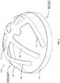
- FIG. 1is a perspective view of an example headset constructed in accordance with the teachings of this disclosure for gathering EEG signals.
- FIG. 2is a plan view of one side (e.g., an inside) of the example headset of FIG. 1 .
- FIG. 3is a plan view of another side (e.g., the outside) of the example headset of FIG. 1 .
- FIG. 4Ais a left side view of the example headset of FIG. 1 .
- FIG. 4Bis a right side view of the example headset of FIG. 1 .
- FIG. 4Cillustrates the example headset of FIG. 1 on a head of a subject.
- FIG. 4Dis a rear view of the example headset of FIG. 1 disposed on a relatively small head.
- FIG. 4Eis a rear view of the example headset of FIG. 1 disposed on a relatively large head.
- FIG. 5is an exploded view of an example electrode unit having example electrodes that may be used with the example headset of FIG. 1 .
- FIG. 6is a partially assembled view of the example electrode unit of FIG. 5 .
- FIG. 7is an assembled view of the example electrode unit of FIG. 5 .
- FIG. 8is a side view of the example electrode unit of FIG. 5 with the example electrodes in an extended position.
- FIG. 9is a side view of the example electrode unit of FIG. 5 with the example electrodes in a retracted or compressed position.
- FIG. 10is a cross-sectional view of the example electrode unit of FIG. 8 taken along line A-A of FIG. 8 .
- FIG. 11is a cross-sectional view of the example electrode unit of FIG. 9 taken along line B-B of FIG. 9 .
- FIG. 12is a perspective view of the example electrode unit of FIG. 5 with the example electrodes in an extended position.
- FIG. 13is a perspective view of the example electrode unit of FIG. 5 with the example electrodes in a retracted position.
- FIG. 14is a cross-sectional view of the example electrode unit of FIG. 12 taken along line C-C of FIG. 12 .
- FIG. 15is a cross-sectional view of the example electrode unit of the FIG. 13 taken along line D-D of FIG. 13 .
- FIG. 16is a perspective view of another example electrode unit having an example electrode that may be used with the example headset of FIG. 1 .
- FIG. 17is a side view of the example electrode unit of FIG. 16 .
- FIG. 18is cross-sectional view of the example electrode unit of FIGS. 16 and 17 taken along line E-E of FIG. 16 .
- FIG. 19is a side view of another example electrode unit having an example electrode that may be used with the example headset of FIG. 1 .
- FIG. 20is another side view of the example electrode unit of FIG. 19 .
- FIG. 21is a cross-sectional view of the example electrode unit of FIGS. 19 and 20 taken along line F-F of FIG. 20 .
- FIG. 22is a perspective view of the example electrode of FIG. 19 in an unassembled state.
- FIG. 23is a top view of the example electrode of FIG. 22 .
- FIG. 24is a side view of the example electrode of FIG. 22 .
- FIG. 25is a perspective view of the example electrode of FIG. 19 in an assembled state.
- FIG. 26is a top view of the example electrode of FIG. 25 .
- FIG. 27is a side view of the example electrode of FIG. 25 .
- FIG. 28is a side view of an example housing of the example electrode unit of FIG. 19 .
- FIG. 29is a bottom view of the example housing of FIG. 28 .
- FIG. 30is a cross-sectional view of the example housing of FIGS. 28 and 29 taken along line G-G of FIG. 28 .
- FIG. 31is a side view of the example electrode unit of FIG. 19 showing the example electrode in a compressed state.
- FIG. 32is another side view of the example electrode unit of FIG. 31 .
- FIG. 33is a cross-sectional view of the example electrode unit of FIGS. 31 and 32 taken along line H-H of FIG. 32 .
- FIG. 34illustrates an example substrate from which multiple ones of the example electrode of FIG. 19 are stamped during an example manufacturing process.
- FIG. 35is an exploded view of another example electrode unit having example electrodes that may be used with the example headset of FIG. 1 .
- FIG. 36is an assembled view of the example electrode unit of FIG. 35 .
- FIG. 37is a side view of the example electrode unit of FIG. 35 .
- FIG. 38is another side view of the example electrode unit of FIG. 35 .
- FIG. 39is a cross-sectional view of the example electrode unit of FIG. 35 taken along line I-I of FIG. 38 .
- FIG. 40is an exploded view of an example shielding unit implemented with the example electrode unit of FIG. 35 .
- FIG. 41is a cross-sectional view of an example pogo-pin electrode that may be implemented as any of the example electrodes disclosed herein.
- Example headsets disclosed hereinmay be used to obtain EEG signals from a brain in the head of a subject.
- Example headsets disclosed hereininclude electrode units that may be removably or permanently coupled to the headsets.
- an electrode unitis magnetically couplable to an example headset.
- the electrode unitsare coupled with mechanical fasteners to the headset such as, for example, a threaded connection or a friction fit.
- Example electrode unitsinclude one or more electrodes.
- the electrode(s)include an electrode body and a pin that is retractable into the electrode body. In some such examples, the pin is biased outward via a spring.
- the electrode(s)include an arm that is bendable or compressible.
- Example electrode units disclosed hereininclude a guide defining an opening and an electrode disposed in the opening.
- the electrodehas a housing, a first spring, and a pin, where the pin is biased outward from a first end of the housing via the first spring.
- the electrode unitfurther includes a second spring disposed over the opening adjacent a second end of the housing.
- the electrodeis a first electrode
- the housingis a first housing and the pin is a first pin.
- the electrode unitfurther includes a second electrode disposed in the opening.
- the second electrodeincludes a second housing, a third spring, and a second pin, where the second pin is biased outward from a first end of the second housing via the third spring.
- the first electrode and the second electrodeare independently adjustable via the first spring and the third spring.
- the first electrode and the second electrodeare simultaneously adjustable via the second spring.
- the housingis coupled to the second spring.
- the housingincludes a protrusion extending through an aperture in the second spring, where the housing is coupled to the second spring via staking or press fit.
- the openingis a first opening
- the electrode unitfurther includes a connector having a second opening.
- the guideis disposed in the second opening of the connector.
- the connectormay be coupled to a band to be disposed over a head of a subject.
- the connectoris a magnet.
- the guideis coupled to the connector via an interference fit.
- the electrode unitfurther includes an electrode unit housing having a third opening defining a cavity, and the connector is disposed in the third opening.
- the electrode unit housingincludes a ledge in the opening, wherein an outer rim of the second spring is coupled between the connector and the ledge. In some examples, an outer rim of the second spring remains in contact with the connector when the center of the second spring flexes into the cavity. In some examples, the second spring is a spiral spring plate.
- Example electrode units disclosed hereininclude a housing defining a cavity, conductive paste disposed on an inner wall of the cavity and an electrode disposed in the cavity and spaced apart from the inner wall of the cavity.
- the electrodeextends from the cavity, and the conductive paste is to shield the electrode from noise.
- the electrode unitincludes a layer of insulation disposed between the electrode and the housing.
- Example headsets disclosed hereininclude the disclosed electrode unit and a band to be disposed over a head of a subject.
- the bandhas an aperture extending through the band.
- the electrode unitis to be coupled to the band and extend through the aperture.
- the headsetincludes a pin coupled to the band adjacent the aperture, and the pin is to engage a bottom of the housing.
- the conductive pasteis further disposed on the bottom of the housing.
- the pinis electrically coupled to a shielding electrode to be placed on the head of the subject. In some such examples, the pin is electrically coupled to the shielding electrode via a printed circuit board disposed in the band.
- the headsetfurther includes a head band, and the shielding electrode is coupled to the head band to contact a forehead of the subject.
- the electrode unitincludes a first connector and the band includes a second connector, where the first connector may be removably coupled to the second connector.
- the first connectoris a magnet and the second connector is a metal.
- the second connectoris a metal ring disposed around the aperture.
- An example shielding unitincludes a bottom cover having an opening extending from a top side to a bottom side of the bottom cover.
- the example shielding unitalso includes a top cover coupled to the top side of the bottom cover.
- Conductive pasteis disposed on a bottom of the top cover.
- the example electrode unitfurther includes a pin disposed in a channel extending through the bottom cover, where the pin is in contact with the conductive paste on the top cover and extends from the bottom side of the bottom cover.
- the pinis a pogo-pin.
- the shielding unitfurther includes an electrode unit and the electrode unit is disposed in the opening in the bottom cover.
- the electrode unitis coupled to the bottom cover via an interference fit.
- the electrode unitincludes an electrode extending from the bottom side of the bottom cover.
- Example headsets disclosed hereininclude the disclosed shielding unit and a band to be disposed over a head of a subject.
- the bandhas an aperture extending through the band, and the shielding unit is coupled to the band and the electrode extends through the aperture.
- the bandincludes an electrical pad adjacent the aperture, where the pin engages the electrical pad.
- the electrical padis electrically coupled to a shielding electrode to be placed on the head of the subject.
- the pinis electrically coupled to the shielding electrode via printed circuit board disposed in the band.
- Some example electrode units disclosed hereininclude a housing having a cavity defined by an opening in a side of the housing and an electrode.
- the electrodeincludes a ring disposed in the opening and an arm, where the arm has a first portion extending outward from the opening away from the housing and a second portion extending from an end of the first portion toward the housing and into the cavity, and the first and second portions connect at a bend.
- the first portion of the armextends through the ring and outward from the opening away from the housing.
- the second portion of the armextends through the ring and into the cavity.
- the cavityincludes a channel extending into the housing. In some such examples, the second portion of the arm is movable into the channel when a force is applied to the bend.
- the electrode unitincludes a connector coupled to the housing around the opening to couple the housing to a band to be worn over a head of a subject.
- the ringis coupled between the connector and the housing.
- the connectoris a magnet.
- the housingincludes a guide, and the guide is to extend through the ring of the electrode to align the electrode in the housing.
- the first portionis to move toward the second portion when a force is applied to the bend.
- the ring and the armare integral.
- Example headsets disclosed hereininclude the disclosed electrode unit and a band to be disposed over a head of a subject.
- the bandincludes an aperture extending through the band, and the electrode unit is coupled to the band and the first portion of the arm extends through the aperture.
- the electrode unitincludes a first connector and the band includes a second connector, where the first connector is removably coupled to the second connector.
- the first connectoris a magnet and the second connector is a metal.
- the second connectoris a metal ring disposed around the aperture.
- FIG. 1shows an example headset 100 for gathering EEG signals from the head of a subject (e.g., a person).
- a subjectmay be any person, user, viewer, participant and/or panelist.
- a panelistmay be, for example, a user registered on a panel maintained by a ratings entity (e.g., an audience measurement company) that owns and/or operates a ratings entity subsystem.
- ratings entitye.g., an audience measurement company
- audience measurement entitiesalso referred to herein as “ratings entities” determine demographic reach for advertising and media programming based on registered panel members. That is, an audience measurement entity enrolls people that consent to being monitored into a panel.
- the audience measurement entityreceives demographic information from the enrolling people so that subsequent correlations may be made between advertisement/media exposure to those panelists and different demographic markets.
- Peoplebecome panelists via, for example, a user interface presented on the media device (e.g., via a website). People become panelists in additional or alternative manners such as, for example, via a telephone interview, by completing an online survey, etc. Additionally or alternatively, people may be contacted and/or enlisted using any desired methodology (e.g., random selection, statistical selection, phone solicitations, Internet advertisements, surveys, advertisements in shopping malls, product packaging, etc.).
- the headset 100includes a body having bands that are shaped to extend over a head of a subject.
- the body 102includes a head band 104 that fits over the head of the subject.
- the head band 104is a continuous ring.
- the body 102includes a first band 106 , a second band 108 and a third band 110 that are positioned to extend over the head of subject from the left to the right sides of the head.
- the first, second and third bands 106 , 108 , 110are coupled to the head band 104 by a midline band 112 .
- the midline band 112extends from the head band 104 and is positioned to extend over the head of the subject from the front to the rear of the head, or from the back to the front of the head (e.g., along the midline), depending on the orientation the headset 100 is worn. In other examples, the headset 100 may be worn in other orientations (e.g., the front of the headset 100 may be positioned on the rear of the head). In some examples, the headset may include more or fewer bands. The number of bands, lengths of bands, shapes of bands, orientation of bands, etc. may be based on the desired number of channels from which EEG signals are to be gathered and/or the desired locations of measurement.
- electrodesare coupled to the body 102 of the headset. In some examples, electrodes are coupled to each of the head band 104 , the first band 106 , the second band 108 , the third band 110 and the midline band 112 . In other examples, only certain ones of the head band 104 , the first band 106 , the second band 108 , the third band 110 and/or the midline band 112 include electrodes. The electrodes may be coupled to apertures formed in the body 102 , as disclosed in further detail herein.
- the head band 104forms a continuous ring. In other examples, the head band 104 may be divided or split, and two ends of the head band 104 may be coupled together.
- the body 102is a substantially unitary part or component (e.g., a monolithic structure formed in one piece in a mold). In other examples, the body 102 may be constructed of multiple parts or components that are coupled (e.g., fastened) together.
- the body 102 of the headset 100is silicone, rubber or plastic. In such examples, the body 102 is relatively flexible yet retains its general shape.
- the headset 100includes apertures to receive electrodes.
- FIG. 2shows a bottom, inside view of the body 102 of the example headset 100 in a flattened positioned
- FIG. 3shows a top, outside view of the body 102 of the example headset 100 in a flattened position.
- the headset 100includes a first aperture 200 a (e.g., an opening, a hole, etc.) formed in the body 102 to receive an electrode.
- an electrodee.g., such as the electrode unit 500 of FIG. 5 , disclosed in further detail here
- the headset 100includes a plurality of apertures for a plurality of electrodes, such as apertures 200 b - 200 n . Any number (n) of apertures may be employed.
- the apertures 200 a - 200 nmay be formed in any of the head band 104 , the first band 106 , the second band 108 , the third band 110 and/or the midline band 112 .
- a first connector 202 ais disposed adjacent the first aperture 200 a , as illustrated in the example of FIG. 3 .
- the first connector 202 ais a metal ring, and an electrode (or electrode unit) may include a magnet to couple the electrode (or electrode unit) to the first connector 202 a .
- the first connector 202 ais magnetic.
- other types of connectorse.g., mechanical connectors
- the first connector 202 aencompasses or surrounds the first aperture 200 a .
- a plurality of connectorsis used, and each of the connectors is associated with a respective one of the plurality of apertures 200 a - 200 n .
- a plurality of connectors 202 a - 202 nis illustrated in FIG. 3 for the plurality of apertures 200 a - 200 n .
- the illustrated exampleassociates a connector with each aperture, fewer connectors than apertures may alternatively be used.
- the headset 100includes a printed circuit board (PCB) (e.g., a substrate on which circuitry may be mounted and/or printed) disposed within the body 102 .
- PCBprinted circuit board
- silicone or another materialmay be molded around a PCB to form the body 102 of the headset 100 .
- the PCBmay be flexible and may include traces or wires to form circuitry.
- the connectors 202 a - 202 ne.g., the wires or traces of the PCB
- the PCBis formed of one board.
- the PCBmay be constructed of multiple sections or portions and/or multiple PCBs may be employed.
- the headset 100may include a first PCB 301 in a first part 302 of the head band 104 , a second PCB 303 in a second part 304 of the head band 104 and a third PCB 305 in a third part 306 of the headset 100 .
- the third part 306includes a portion of the head band 104 , the first band 106 , the second band 108 , the third band 110 and the midline band 112 .
- the PCBs 301 , 303 , 305may be in circuit (e.g., in electrical and/or magnetic connection) to form an overall circuit (or compound PCB) extending throughout the body 102 of the headset 100 .
- relatively smaller PCBs or PCB sectionscan be cut from one piece of PCB material to thereby reduce waste compared to cutting the entire headset PCB in one piece.
- the templatescan be arranged closer together to minimize waste between adjacent pieces.
- employing multiple PCBsresults in increased adjustability and movement between sections of the head band 104 , and avoids large areas of rigidity, which might be exhibited by a large PCB.
- employing multiple PCBs 301 , 303 , 305increases comfort for the wearer of the headset 100 .
- the headset 100may include one or more tension straps to tighten the headset 100 on the head of a subject.
- FIG. 4Ais a left side view of the example headset 100 .
- a first tension strap 400(e.g., a cord) is coupled to one end of the first band 106
- a second tension strap 402is coupled to one end of the second band 108
- a third tension strap 404is coupled to one end of the third band 110 .
- the first, second and third tension straps 400 , 402 , 404are elastic (e.g., rubber and/or silicone).
- the first, second and third tension straps 400 , 402 , 404are coupled to a cover 406 (e.g., a connector).
- a pull strap 408is coupled between the cover 406 and a first connector 410 .
- the first connector 410may be pulled to tighten the first, second and third tension straps 400 , 402 , 404 and, thus, to tighten the first, second and third bands 106 , 108 , 110 over the head of a subject.
- the cover 406operates as connector or joiner where the straps 400 , 402 , 404 , 408 are coupled.
- the straps 400 , 402 , 404 , 408are coupled to each other and the cover 406 covers the connection.
- the first connector 410couples to another connector extending from the right side of the headset 100 (disclosed in further detail herein).
- the first, second and/or third bands 106 , 108 , 110may be tightened or loosened together (e.g., simultaneously) by, for example, pulling or relaxing the pull strap 408 . Additionally or alternatively, the first, second and/or third bands 106 , 108 , 110 may be independently adjusted.
- the first tension strap 400extends through a first opening 401 in the first band 106 (e.g., adjacent the end of the first band 106 ).
- the first opening 401is dimensioned to create friction between the first band 106 and the first tension strap 400 .
- the friction forceis sufficient to couple the first tension strap 400 to the first band 106 when pulling the cover 406 , for example.
- the end of the first tension strap 400may be pulled (with sufficient force to overcome the friction) to slide the first tension strap 400 through the first opening 401 .
- the first tension strap 400can be pulled from the opposite side of the first band 106 .
- teethare provided in the first opening 401 .
- An example assembly and cross-sectionals viewsare shows in the enlarged portion of FIG. 4A .
- an end cap 407is coupled to the end of the first band 16 .
- the end capincludes a passage 409 having teeth 411 .
- the teeth 411are angled to create friction against the first tension strap 400 when pulling the first tension strap 400 toward the head band 104 to loosen the first tension strap 400 .
- the second band 108includes a second opening 403 through which the second tension strap 402 extends
- the third band 110includes a third opening 405 through which the third tension strap 404 extends. Therefore, the first, second and third tensions straps 400 , 402 , 404 may be adjusted independently of each other.
- the head band 104includes one or more passageways for the first, second and/or third tension straps 400 , 402 , 404 .
- a first passageway 412e.g., a channel, a through-hole, etc.
- the first tension strap 400extends through the first passageway 412 .
- a second passageway 414 and a third passageway 416are similarly provided for the second and third tension straps 402 , 404 .
- two or more of the first, second and/or third tension straps 400 , 402 , 404extend through the same passageway.
- FIG. 4Bis a right side view of the example headset 100 . Similar to the left side (see FIG. 4A ), the right side includes a fourth tension strap 418 (e.g., a cord), which may be coupled to the other end of the first band 106 opposite the first tension strap 400 ( FIG. 4A ), a fifth tension strap 420 coupled to the other end of the second band 108 opposite the second tension strap 402 ( FIG. 4A ), and a sixth tensions strap 422 coupled to the other end of the third band 110 opposite the third tension strap 404 ( FIG. 4A ).
- the fourth, fifth and sixth tension straps 418 , 420 , 422are coupled to a second cover 424 . Similar to the passageways 412 , 414 , 416 ( FIG.
- the headset 100includes one or more passageways for the fourth, fifth and/or sixth tension straps 418 , 420 , 422 .
- a pull strap 426is coupled between the second cover 424 and a second connector 428 .
- the cover 406operates as connector or joiner where the straps 418 , 420 , 422 , 426 are coupled.
- the second connector 428may be pulled to tighten the fourth, fifth and sixth tension straps 418 , 420 , 422 and, thus, to tighten the first, second and third bands 106 , 108 , 110 over the head of a subject.
- the fourth, fifth and sixth tension straps 418 , 420 , 422are independently adjustable by sliding the tension straps 418 , 420 , 422 through the respective openings to increase or decrease the effective length of the respective straps 418 , 420 , 422 .
- the first connector 410( FIG. 4A ) and the second connector 428 ( FIG. 4B ) may be pulled taut and coupled to each other (e.g., beneath the chin of the wearer, behind the head of the wearer, etc.) to retain the headset 100 to a head of a subject.
- FIG. 4Cillustrates the example headset 100 on a head 430 of a subject.
- the first connector 410is coupled to the second connector 428 at a rear of the head 430 .
- the first connector 410is implemented as a loop and the second connector 428 is implemented as a hook.
- first and second connectors 410 , 428may be other types of connectors, such as a button, a snap, a magnet, Velcro®, and/or any other suitable fastener.
- first and second connectors 410 , 428are connected under a chin of the subject.
- the headset 100includes the electrical connector 300 to which a processor (e.g., a controller, a microprocessor, a central processing unit (CPU), an application-specific integrated circuit (ASIC) or the like) can be connected.
- a processore.g., a controller, a microprocessor, a central processing unit (CPU), an application-specific integrated circuit (ASIC) or the like
- the headset 100may include one or more PCBs disposed within the body 102 (e.g., integrated within the body 102 ).
- the PCB(s)include traces or wires that communicatively couple one or more electrode(s) positioned in respective ones of the apertures 200 a - 200 n to the electrical connector 300 .
- signals gathered by the electrodesare transmitted to the processor for collection and/or analysis.
- An example processor 434is illustrated in FIG. 4C .
- the example processor 434includes an electrical connector 436 that can be plugged into the electrical connector 300 .
- the processor 434conditions the signals, filters/attenuates noise, provides additional signal processing and/or signal analysis and/or outputs data to an external device.
- the processor 434includes a transmitter to transmit signals gathered by the electrodes and/or data based on such signals.
- the two ends of the head band 104are coupled together via a latch or lock 438 .
- the head band 104is divided into the first part 302 and the second part 304 , which extend from the midline band 112 .
- the first part 302is shorter than the second part 304 .
- the lock 438 connecting the ends of the first and second parts 302 , 304is offset from a rear of the head 430 of the subject (e.g., not position in the middle of the back of the head 430 ).
- one or more electrodescan be positioned on the rear section of the head band 104 along the rear of the head 430 , which is beneficial to gather EEG signals that are generated along the midline of the head near the rear or inion.
- FIG. 4Dshows a rear view of the headset 100 on a relatively small head.
- the back of the head band 104includes four apertures (and connectors) where electrodes can be connected (and gather signals).
- the head band 104includes the first aperture 200 a , the second aperture 200 b , the third aperture 200 c and a fourth aperture 200 d .
- the third aperture 200 cis located along (or near) the midline of the head 430 .
- the third aperture 200 cmay be used with an electrode to gather signals from the midline of the head 430 .
- the second aperture 200 bwhich is to the left of the midline
- the fourth aperture 200 dwhich is to the right of the midline, may be used with electrodes to gather signals to the immediate left and right, respectively, of the midline. Therefore, the midline, the left midline and the right midline locations may be accessed by electrodes.
- the first aperture 200 amay be left empty (no electrode inserted) or not activated.
- FIG. 4Eshows the headset 100 on a larger head.
- the second aperture 200 bis disposed along the midline of the head 430 .
- the second aperture 200 bmay be used with an electrode to gather signals from the midline
- the first aperture 200 a and the third aperture 200 cmay be used to gather left and right midline signals, respectively. Therefore, the example headset 100 can be used to obtain signals from the same three locations (a midline, a left and a right) when used on different sized heads.
- supports 440 a - 440 nare provided around the respective apertures 200 a - 200 n .
- the supports 440 a - 440 nprovide support and centering for the electrodes that may be attached to and extend through the respective apertures 200 a - 200 n .
- a first support 440 ais provided around first aperture 200 a
- a second support 440 bis provided around the second aperture 200 b
- the supports 440 a - 440 nare constructed of plastic.
- the example headset 100includes the lock 438 .
- the lock 438includes a release tab 442 that moves between a locked position and an unlocked position.
- the release tab 442is in the locked position (to the left in FIG. 4D ).
- the example headset 100includes a first top wire 444 a and a first lower wire 444 b .
- the first top and bottom wires 444 a , 444 bextend along the left side of the headset 100 .
- the first top and bottom wires 444 a , 444 bare coupled to a fifth support 440 e of a fifth electrode aperture 200 e on the left side of the head band 104 .
- the first top and bottom wires 444 a , 444 bextend rearward and pass through respective channels in a sixth support 440 f and a seventh support 440 g .
- Example channelsare illustrated on the sixth support 440 f in FIG. 4A (shown in dashed lines).
- the first top and bottom wires 444 a , 444 bextend through channels in the first support 440 a , through channels in the release tab 442 , and through channels in the second support 440 b .
- the first top and bottom wires 444 a , 444 bare coupled to a pull tab 446 .
- the channels in the release tab 442are offset from the channels in the first support 440 a .
- the path for the first top and bottom wires 444 a , 444 bcreates friction that prevents the first support 440 a from sliding along the first top and bottom wires 444 a , 444 b .
- FIG. 4Dis an enlarged partial cross-sectional view of the first support 440 a , the release tab 442 and the second support 440 b showing example channels.
- the first support 440 aincludes a first channel 441 and the release tab 442 includes a second channel 443 .
- the first channel 441is slanted or angled with respect to the second channel 443 , such that the first and second channels 441 , 443 are not aligned when the first support 440 a and the release tab 442 are adjacent each other.
- the release tab 442is in the locked position (to the left)
- the first top wire 444 ais forced to bend through the channels 441 , 443 , which creates friction, thereby preventing the first support 440 a from sliding along the first top wire 444 a .
- the ends of the head band 104are locked in place relative to each other.
- the release tab 442is moved to the right (towards the second support 440 b ), which reduces or eliminates the friction.
- the first top and bottom wires 444 a , 444 bcan slide freely through the first and second supports 440 a , 400 b and the release tab 442 .
- the pull tab 446can be pulled to the right to move the ends (the parts 302 , 304 of FIG. 3 ) of the head band 104 toward each other, or can be moved back to the left to release the tensions and allow more space between the ends of the head band 104 , as illustrated in FIG. 4E .
- the first top and bottom wires 444 a , 444 bincrease the structural integrity of the head band 104 .
- the head band 104is constructed of rubber (or another flexible material) and may tend to bend away from the head 430 . In such an instance, the first top and bottom wires 444 a , 444 b hold or support the head band 104 in place.
- the first top and bottom wires 444 a , 444 bare steel wires. In some examples, more than two wires may be implemented. In other examples, only one wire may be implemented instead of two. In some examples, the wire(s) may be coupled to other ones of the supports 440 a - 440 n and/or to other locations on the head band 104 .
- a spacer 448is provided support the extra length of the first top and bottom wires 444 a , 444 b .
- the spacer 448is movable along the head band 104 .
- the spacer 448is moved further to the right.
- the headset 100includes a second top wire 450 a and a second bottom wire 450 b , which extend along the right side of the headset 100 .
- the second top and bottom wires 450 a , 450 bare coupled to an eighth support 440 h and extend rearward through channels in a ninth support 440 i , a tenth support 440 j , etc.
- the second top and bottom wires 450 a , 450 bextend channels in the supports along the back of the head 440 and are coupled to the second support 440 b .
- the second top and bottom wires 450 a , 450 balso provide structural integrity to the head band 104 .
- the second top and bottom wires 450 a , 450 bare steel wires.
- the wire(s)may be coupled to other ones of the supports 440 a - 440 n and/or to other locations on the head band 104 .
- other tightening mechanisms and/or lock mechanismsmay be implemented on the headset 100 .
- the head band 104may be split or divided differently to dispose the lock 438 in other locations on the head 430 to ensure electrodes may be placed on areas desirable for EEG signal collection.
- a processor support 452( FIGS. 4D and 4E ) is coupled to the headset 100 to support a processor (e.g., the processor 434 of FIG. 4C ) when attached to the headset 100 .
- FIG. 5shows an example electrode unit 500 that may be used with the example headset 100 of FIGS. 1-4E or another headset.
- the electrode unit 500may be coupled to the first aperture 200 a of FIGS. 2 and 3 , for example. In some examples, multiple ones of the electrode unit 500 are used with the example headset 100 of FIGS. 1-4E .
- the electrode unit 500includes a pusher 502 , a spring 504 , a connector 506 , a guide 508 , a first electrode 510 , a second electrode 512 and a housing 514 .
- the guide 508defines an opening 516 .
- the first and second electrodes 510 , 512are slidably disposed within the opening 516 (e.g., a passage, a through-hole).
- the guide 508is dimensioned to be disposed within an opening 518 in the connector 506 .
- the guide 508is coupled to the connector 506 via an interference fit (e.g., friction or press fit).
- a chemical fastenersuch as an adhesive and/or a mechanical fastener(s) may be used to couple the guide 508 to the connector 506 .
- the connector 506is ring-shaped.
- the spring 504is dimensioned to be disposed over the connector 506 and the guide 508 .
- the spring 504is a spiral spring plate. In an unbiased or relaxed position, the spring 504 is substantially flat or planar, as shown in the position in FIG. 5 .
- the guide 508(with the first and second electrodes 510 , 512 ), the connector 506 and the spring 504 are dimensioned to be disposed in a cavity 520 of the housing 514 , such that the first and second electrodes 510 , 512 extend from a bottom 522 of the housing 514 .
- a first opening 521 in the housing 514 and a second opening 523 in the opposite side of the housing 514define the cavity 520 .
- the second spring 504is disposed over the connector 506 and the guide 508 in the cavity 520 .
- the connector 506is coupled to the housing 514 via an interference fit (e.g., friction or press fit). Additionally or alternatively, in some examples a chemical fastener such as an adhesive and/or a mechanical fastener(s) may be used to couple the connector 506 to the housing 514 .
- the electrodes 510 , 512are implemented as pins. However, in other examples, the electrodes may have other desired shapes such as, for example, rings, balls, hook-shaped, etc.
- the spring 504 , the connector 506 ( FIG. 5 ) and the guide 508 ( FIG. 5 ) (with the first and second electrodes 510 , 512 )are disposed within the housing 514 .
- the pusher 502 of this exampleincludes a top 524 and a wall 526 extending from the top 524 .
- the pusher 502 of this examplemay be inserted into the cavity 520 ( FIG. 5 ) of the housing 514 (through the second opening 523 ( FIG. 5 ) of the housing 514 ).
- the wall 526 ( FIGS. 5 and 6 )is received within the cavity 520 ( FIG. 5 ).
- the top 524( FIGS. 5 and 6 ) includes a lip 527 , the bottom surface of which engages a top 528 ( FIG. 5 ) of the housing 514 .
- the pusher 502is coupled to the housing 514 via an interference fit (e.g., friction or press fit). Additionally or alternatively, in some examples a chemical fastener such as an adhesive and/or a mechanical fastener(s) may be used to couple the pusher 502 to the housing 514 .
- FIG. 8is a side view of the example electrode unit 500 with the first and second electrodes 510 , 512 ( FIG. 5 ) in the extended position
- FIG. 9is a side view of the example electrode unit 500 with the first and second electrodes 510 , 512 ( FIG. 5 ) in the retracted position
- FIG. 10is a cross-sectional view of the electrode unit 500 of FIG. 8 taken along line A-A of FIG. 8
- FIG. 11is a cross-sectional view of the electrode unit 500 of FIG. 11 taken along line B-B of FIG. 9 .
- the guide 508is received within the connector 506
- the connector 506is received within the cavity 520 of the housing 514
- the connector 506is substantially aligned with the bottom 522 ( FIGS. 10 and 11 ) of the housing 514 , and the guide 508 and the first and second electrodes 510 , 512 extend from the bottom 522 of the housing 514 .
- the first electrode 510includes a first electrode body 1000 (e.g., a housing, a sheath) and a first pin 1002 (e.g., a pogo pin).
- the first electrode body 1000receives the first pin 1002 within a first cavity 1004 of the first electrode body 1000 .
- the first pin 1002 of the illustrated exampleis retractable into the first cavity 1004 and biased outward from the first electrode body 1000 (e.g., from an end of the first electrode body 1000 ) by a first spring 1006 that is disposed within the first cavity 1004 .
- a tip 1008 of the first pin 1002contacts the scalp of the head of a subject and senses the EEG signals.
- the first spring 1006allows the first pin 1002 to retract into the first electrode body 1000 when force is applied downward against the scalp and, thus, increases the comfort and wearability of the headset (e.g., the headset 100 of FIG. 1 ) by reducing the pressure the first electrode 510 applies to the scalp.
- the first pin 1002is coupled (e.g., via welding) to one end of the first spring 1006 , and the other end of the first spring 1006 is coupled to the first electrode body 1000 .
- the first pin 1002may include a leg or lip that abuts a rim around the inside of the first cavity 1004 .
- the leg or lipmay be forced passed the rim (e.g., via a snap fit) when first inserting the first pin 1002 into the first cavity 1004 .
- a chemical fastenersuch as an adhesive and/or a mechanical fastener(s) may be used prevent the first pin 1002 from being completely ejected from the first electrode body 1000 .
- Different size springs or springs of different materialmay be utilized with the first electrode 510 to provide more or less biasing force.
- the first spring 1006provides around 0.2 Newtons of force.
- the first spring 1006is a coil spring.
- the first spring 1006may be implemented by any other type of spring such as, for example, a leaf spring.
- the second electrode 512is substantially the same as (e.g., identical to) the first electrode 510 .
- the second electrode 512includes a second electrode body 1000 , a second pin 1002 , a second cavity 1004 , a second spring 1006 and a second tip 1008 .
- the second electrode 512operates substantially the same as the first electrode 510 .
- the interested readeris referred to the disclosure above relating to the first electrode 510 for a complete description of the second electrode 512 .
- the spring 504( FIG. 10 ) is substantially flat, and the ends of the first electrode body 1000 of the first electrode 510 and the second electrode body 1000 of the second electrode 512 are disposed flush with the opening 516 of the guide 508 (see FIG. 10 ).
- the first pin 1002 of the first electrode 510extends from the first cavity 1004 (e.g., from a first end) of the first electrode body 1000
- the second pin 1002 of the second electrode 512extends from the second cavity 1004 of the second electrode body 1000 .
- the second spring 504is disposed over the opening 516 adjacent the first top 1010 and the second top 1010 of the first and second electrodes 510 , 512 .
- the first top 1010 and/or the second top 1010are coupled to the spring 504 .
- the outer rim/perimeter of the spring 504is coupled (e.g., retained) between the wall 526 of the pusher 502 and the connector 506 , which are coupled to the housing 514 (e.g., via an interference fit).
- the pusher 502provides force to keep the spring 504 in contact with the connector 506 (e.g., for communicating EEG signals therethrough). In some examples, the pusher 502 covers the internal components of the electrode unit 500 to prevent accidently damage and/or contact with the spring 504 .
- the first electrode 510is coupled (e.g., fixedly coupled) to the spring 504 via staking or press fit.
- the first electrode 510includes a first protrusion 530 (e.g., a boss) (as shown in FIGS. 5 and 10 ) extending from the first top 1010 of the first electrode body 1000 .
- the spring 504includes a first aperture 532 (e.g., a hole). The first protrusion 530 is inserted into the first aperture 532 and flattened or deformed (e.g., via a staking punch, or heat) to fasten the first electrode 510 to the spring 504 .
- the second electrode 512includes a second protrusion 530 (e.g., a boss) (as shown in FIGS. 5 and 10 ) extending from the second top 1010 of the second electrode body 1000
- the spring 504includes a second aperture 536 through which the second protrusion 530 can be inserted and fastened (e.g., via deformation).
- other mechanical and/or chemical fastener(s)may be used to couple the first electrode 510 and/or the second electrode 512 to the spring 504 .
- the first electrode 510 and/or the second electrode 512may be soldered to the spring 504 .
- the first electrode 510 and the second electrode 512are independently adjustable via the respective the springs 1006 .
- the first and second electrodes 510 , 512have been forced through the opening 516 in the guide 508 and into the spring 504 such that the tops 1010 are disposed above the opening 516 and further within the guide 508 (see FIG. 11 ).
- the first and second electrodes 510 , 512are movable through the opening 516 of the guide 508 into the cavity 520 of the housing 514 .
- the spring 504flexes to enable this movement of the first and second electrodes 510 , 512 to the retracted position.
- the springs 1006 within the individual electrodes 510 , 512compress when subjected to force.
- the spring 504 and the springs 1006provide an additive force on the scalp.
- the springs 1006 in the electrodes 510 , 512enable the electrode pins 1002 to independently adjust to bumps and curves on the scalp.
- the first pin 1002has been retracted into the first electrode body 1000 and the second pin 1002 has been retracted into the second electrode body 1000 , which further softens the force against the scalp and increases comfort.
- the first electrode body 1000 and the second electrode body 1000are independently movable, depending on the placement of the electrodes, the curvature of the scalp, an amount of hair, and/or a degree to which the bands are tightened or loosened, the first electrode body 1000 may extend a first distance from the guide 508 , and the second electrode body 1000 may extend a second distance from the guide 508 . In some examples, the second distance is different than the first. In some examples, the first electrode 510 and second electrode 512 are simultaneously adjustable via the spring 504 and independently adjusted via the springs 1006 .
- the connector 506is magnetic.
- the electrode unit 500may be magnetically coupled to the body 102 .
- the first connector 202 a of FIG. 3is a magnetic ring and the connector 506 ( FIGS. 5, 10 and 11 ) is a magnetic ring.
- the first connector 202 a and the connector 506magnetically couple the electrode unit 500 to the body 102 .
- bottom of the guide 508extends into the first aperture 200 a
- the first and second electrodes 510 , 512extend through the first aperture 200 a and outward from the bottom of the body 102 .
- the connectors 202 a , 506may be other types of connectors. These magnetic couplings (or other releasable mechanical couplings) allow the electrode units 500 to be independently coupled to the headset 100 . As such, the independently couplable electrode units 500 can be repaired or replaced individually, which extends the useful life of the headset 100 by enabling replacement of individual electrode units 500 instead of the entire headset 100 .
- the first and second electrodes 510 , 512sense EEG signals from the scalp of a subject. The signals are transferred from the pins 1002 through the electrode bodies 1000 , the spring 504 , and the connector 506 to the first connector 202 a .
- a PCBmay be disposed within the body 102 to electrically couple the first connector 202 a to the processor 434 ( FIG. 4C ) and/or a transmitter.
- the first and second electrodes 510 , 512 and the spring 504are electrically conductive, whereas the guide 508 and the housing 514 are not electrically conductive.
- first and second electrodes 510 , 512 and the spring 504may be metallic (e.g., steel, silver, silver-chloride, chromium, gold, etc.) and the guide 508 and the housing 514 may be plastic or rubber and/or other suitable material(s) or combination of material(s).
- the electrode unit 500includes two electrodes. However, in other examples, the electrode unit 500 may include more or fewer electrodes and/or pins. For example, the electrode unit 500 may include only one electrode. In another example, the electrode unit 500 may include three electrodes, four electrodes, ten electrodes, etc.
- FIG. 12shows the spring 504 , the connector 506 , the guide 508 and the first and second electrodes 510 , 512 of the electrode unit 500 ( FIG. 5 ) in the extended position, similar to FIGS. 8 and 10 .
- the pusher 502 and the housing 514have been removed for clarity.
- the spring 504is relaxed or in an unbiased state.
- FIG. 13shows the spring 504 in a biased state, similar to FIG. 11 .
- the first and second electrodes 510 , 512( FIG. 12 ) are pushed upward through the guide 508 and onto the bottom of the spring 504 .
- a middle of the spring 504flexes upward.
- the spring 504biases the first and second electrodes 510 , 512 downward.
- FIG. 14is a cross-sectional view of the spring 504 , the connector 506 , the guide 508 and the first and second electrodes 510 , 512 taken along line C-C of FIG. 12 , showing the first and second electrodes 510 , 512 in the extended position, similar to FIG. 10 .
- FIG. 15is a cross-sectional view of the spring 504 , the connector 506 , the guide 508 and the first and second electrodes 510 , 512 taken along line D-D of FIG. 13 , showing the first and second electrodes in the retracted position, similar to FIG. 11 .
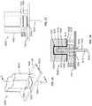
- FIGS. 16-18illustrate another example electrode unit 1600 that may be used with the example headset 100 of FIGS. 1-4E .
- the electrode unit 1600is illustrated as coupled to the head band 104 of the headset 100 ( FIG. 1 ).
- the electrode unit 1600includes an electrode 1602 , a housing 1604 , a connector 1606 and insulation 1608 .
- the electrode 1602includes an electrode body 1610 (e.g., a housing, a sheath) and a pin 1612 (e.g., a pogo pin).
- the electrode body 1610receives the pin 1612 within a cavity 1614 of the electrode body 1610 .
- the pin 1612 of the illustrated exampleis retractable into the cavity 1614 and biased outward from the electrode body 1610 by a spring 1616 that is disposed within the cavity 1614 .
- a tip 1618 of the pin 1612contacts the scalp of the head of a subject and senses the EEG signals.
- the insulation 1608 and the electrode body 1610are disposed within a cavity 1620 of the housing 1604 .
- the insulation 1608is located between the electrode body 1610 and an inner wall 1622 of the cavity 1620 .
- the cavity 1620is implemented as a blind hole.
- the bands 104 , 106 , 108 , 110 , 112 of the headset 100include the plurality of apertures 200 a - 200 n extending through the bands 104 , 106 , 108 , 110 , 112 , and the plurality of connectors 202 a - 202 n are disposed around the apertures 200 a - 200 n .
- the electrode unit 1600is illustrated as coupled to the first aperture 200 a .
- the electrode 1602extends through the first aperture 200 a .
- the connector 1606is a magnet
- the first connector 202 ais a metal ring.
- the electrode unit 1600is magnetically coupled to the head band 104 , and, thus, releasably coupled thereto.
- the connector 1606is disposed between a flange 1623 extending from the electrode body 1610 and the insulation 1608 .
- the attractive force between the connector 1606 and the first connector 202 aretains in the electrode unit 1600 on the head band 104 .
- the connector 1606 and the first connector 202 amay be other types of connectors to removably couple the electrode unit 1600 to the head band 104 .
- a PCB 1624is disposed within (e.g., entirely encased in) the head band 104 .
- the PCB 1624communicatively couples the first connector 202 a to the electrical connector 300 ( FIG. 4C ). Signals gathered by the electrode 1602 are transferred from the electrode pin 1612 , through the electrode body 1610 and the flange 1623 , to the first connector 202 a , to the PCB 1624 and, thus, to the electrical connector 300 . Because the PCB 1624 acts primarily as a conductor and need not include logic circuitry, in some examples the PCB 1624 is replaced with other conductors such as wires.
- the head band 104includes an electrical pin 1626 adjacent the first aperture 200 a .
- the electrical pin 1626contacts a bottom 1628 of the housing 1604 .
- a layer of conductive paint or paste 1630is disposed on the bottom 1628 of the housing and along the inner wall 1622 of the cavity 1620 .
- the electrical pin 1626is coupled (e.g., soldered) to the PCB 1624 .
- a wire or trace in the PCB 1624electrically couples the pin 1626 to a shielding electrode, which may be in contact with the head (e.g., forehead) of the subject.
- the paste 1630is in electrical connection with the body of the wearer, which acts as an extension of the body that surrounds the electrode 1602 , thereby shielding the electrode 1602 from any interference or noise in the environment. For example, referring back to FIG.
- the example headset 100includes six flat electrodes 204 a , 204 b , 204 c , 204 d , 204 e , 204 f coupled to the head band 104 (e.g., molded in the body 102 of the head band 104 ) and disposed along the forehead side of the head band 104 .
- the flat electrodes 204 a - 204 fare communicatively coupled to the PCB 1624 in the body 102 of the headset 100 and/or to other wires or traces disposed in the body 102 of the headset 100 .
- one of the flat electrodes 204 a - 204 fis a shielding electrode, which is communicatively coupled to the pin 1626 (and other pins associated with the other apertures 200 a - 200 n ).
- three of the flat electrodes 204 a - 204 fare to gather EEG signals, one of the flat electrodes 204 a - 204 f is a ground electrode, one of the flat electrodes 204 a - 204 f is a reference or feed-back electrode and one of the flat electrodes 204 a - 204 f is a shielding electrode.
- one or more of the flat electrodes 204 a - 204 fmay have different functions. In some examples, more or fewer flat electrodes are implemented.
- a shield layer(e.g., a layer of silver or copper) is disposed on top of the PCB 1624 (or molded into the body 102 of the headset 100 over the PCB 1624 ) and integrated throughout the body 102 of the headset 100 .
- the shield layeris also electrically coupled to the shielding electrode on the forehead of the subject and, thus, shields the PCB 1624 in a similar manner.
- the shield layeris electrically coupled to a shield layer in the processor 434 (which is disposed over the electrical components in the processor 434 ) to likewise shield any electrical components in the processor 434 .
- a passive shieldcan be formed around the electrical components of the headset 100 .
- a chargemay be provided to the pin 1626 and are distributed throughout the paste 1630 to block noise and interference.
- a metallic mesh or patterne.g., a cage
- the electrical pin 1626is biased upward from the head band 104 (e.g., via a spring, similar to the first spring 1006 and the first pin 1002 in FIG. 10 ) such that the electrical pin 1626 retracts into a base or body when contacted by the housing 1604 .
- the electrical pin 1626is integrated with the electrode unit 1600 and contacts a pad near the first aperture 200 a when connected to the headset 100 (disclosed in further detail here).
- the electrode unit 1600is illustrated as coupled to the head band 104 . However, in other examples, the electrode unit 1600 may be similarly coupled to other ones of the bands (e.g., the first band 106 , the second band 108 , the third band 110 , or the midline band 112 ). In some examples, multiples electrode units similar (e.g., identical) to the electrode unit 1600 are coupled to the headset 100 ( FIGS. 1-4E ).
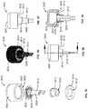
- FIGS. 19, 20 and 21illustrate another example electrode unit 1900 that may be used with the example headset 100 of FIGS. 1-4E .
- the electrode unit 1900includes an electrode 1902 , a housing 1904 and a connector 1906 .
- the interior structure of the housing 1904is shown in dashed lines.
- the electrode 1902includes an arm 1908 and a ring 1910 .
- the housing 1904includes a cavity 1912 .
- the ring 1910 of the electrode 1902is disposed around an opening 1914 of the cavity 1912 .
- the ring 1910is coupled between the connector 1906 and a bottom 1916 of the housing 1904 .
- the arm 1908is bent or curved in this example.
- a first end of the arm 1908is coupled to the ring 1910 , and the other end of the arm 1908 extends through an opening 1918 of the ring 1910 and into the cavity 1912 of the housing 1904 (see also FIG. 25 ).
- the example electrode unit 1900may be coupled to one of the apertures 200 a - 200 n of the headset 100 of FIGS. 1-4 .
- the connector 1906is a magnet
- the connectors 202 a - 202 n( FIG. 3 ) are metal rings.
- the connector 1906magnetically couples the electrode unit 1900 to one of the connectors 202 a - 202 n .
- the arm 1908 of the electrode 1902extends through the respective aperture 200 a - 200 n to contact the scalp of a subject when the headset 100 is disposed on the head of the subject.
- the example electrode 1902is in an uncompressed state.
- Signals gathered by the electrode 1902are transferred through the connector 1906 to the connector 202 a - 202 n and to the electrical connector 300 ( FIG. 3 ) via the PCB (or other connective wiring) disposed within the body 102 of the headset 100 .
- FIGS. 22-24illustrate the example electrode 1902 in an unassembled (e.g., unshaped or unbent) state or form.
- the electrode 1902may be stamped or cut from a substrate such as, for example, a sheet of silver, silver-chloride, chromium, gold, and/or any other suitable metal(s), alloy(s) or other conductive material(s) or combination thereof.
- the electrode 1902includes the ring 1910 and the arm 1908 extending from the ring 1910 .
- FIGS. 25-27illustrate the electrode 1902 in an assembled state or form. To form the electrode 1902 from the unassembled electrode 1902 of FIG.
- the arm 1908is bent over the ring 1910 , inserted through the opening 1918 and creased or bent, such that a portion of the arm 1908 extends back through the opening 1918 .
- a first portion 2500 of the arm 1908extends downward from the ring 1910 (through the opening 1918 ) and, at a corner or bend 2502 , a second portion 2504 of the arm 1908 extends back upward through the opening 1918 of the ring 1910 .
- the first and second portions 2500 , 2504are coupled at the bend 2502 .
- the first and second portions 2500 , 2504are integral.
- the electrode 1902as illustrated in FIG.
- the 25may be formed by bending the arm 1908 over the ring 1910 and through the opening 1918 .
- the arm 1908may be bent downward on the outside of the circumference of the ring 1910 , bent or creased to form the corner or bend 2502 and positioned back through the opening 1918 of the ring 1910 .
- Other examplesinclude a curve in place of the bend 2502 , which may be used, for example, to increase the surface area of the connection of the electrode 1902 on the scalp and/or provide increased comfort to the subject.
- FIGS. 28-30illustrate the example housing 1904 of the electrode unit 1900 ( FIG. 19 ).
- FIG. 28is a side view of the housing 1904
- FIG. 29is a bottom view of the housing 1904
- FIG. 30is a cross-sectional view of the housing 1904 taken along line G-G of FIG. 28 .
- the cavity 1912extends into the housing 1904 from the opening 1914 in the bottom 1916 .
- a first groove or recess 2900is formed around the opening 1914 .
- the first recess 2900is sized to receive the connector 1906 ( FIG. 19 ).
- a second groove or recess 2902is formed above the first recess 2900 and is sized to receive the ring 1910 ( FIG.
- the connector 1906is retained in the first recess 2900 via an interference fit (e.g., friction fit).
- an interference fite.g., friction fit
- chemical, magnetic, and/or mechanical fastenersmay be used to couple to the connector 1906 to the housing 1904 .
- the cavity 1912includes a first channel 2904 (e.g., a slot) and a second channel 2906 extending into the housing 1904 .
- first channel 2904e.g., a slot
- second channel 2906extending into the housing 1904 .
- the electrode 1902can be oriented in one of two orientations (e.g., with the second portion 2504 extending into the first channel 2904 or the second channel 2906 ).
- the cavity 1912may include only one channel.
- the cavity 1912may include more than two channels, or may include a continuous channel such that electrode 1902 can be positioned in the housing 1904 in any orientation.
- a guide 2908is disposed within the cavity 1912 .
- the guide 2908is a cylinder that extends from an inner wall of the cavity 1912 and is sized to receive the ring 1910 of the electrode 1902 and align the electrode 1902 within the opening 1914 of the housing 1904 .
- the guide 2908includes a first slot 2910 that is aligned with the first channel 2904 of the cavity 1912 and a second slot 2912 that is aligned with the second channel 2906 of the cavity 1912 .
- the arm 1908 of the electrode 1902can extend through one of the first or second slots 2910 , 2912 and into the respective first or second channel 2904 , 2906 of the cavity 1912 .
- FIGS. 31-33illustrate the example electrode 1902 of the electrode unit 1900 in a bent or compressed state, such as when the electrode 1902 is in contact with the scalp of a subject.
- the interior structure of the housing 1904is shown in dashed lines.
- the electrode 1902when the electrode unit 1900 is attached to a headset (e.g., the headset 100 of FIGS. 1-4 ), the electrode 1902 extends through an aperture in the headset to contact the head of a subject.
- the bend 2502contacts the head of the subject.
- the arm 1908bends or compresses to reduce or soften the contact between the bend 2502 and the scalp of the subject.
- the electrode 1902acts as a spring to biases the bend 2502 downward from the opening 1914 .
- the electrode 1902has a similar mechanical movement as a leaf spring. As illustrated in FIGS. 31-33 , when a force is applied to the bend 2502 (e.g., resistance from the scalp of the subject when the headset 100 is tightened), the first portion 2500 and the second portion 2504 of the arm 1908 bend or curve. In some examples, the first portion 2500 moves toward the second portion 2504 when force is applied to the bend 2502 . As the bend 2502 is moved upward toward the opening 1914 , the second portion 2504 of the arm 1908 slides into the first channel 2904 of the cavity 1912 . Referring back to FIGS. 22, 23, and 25 , the ring 1910 includes a notch 2506 formed in the rim of the opening 1918 .
- the second portion 2504when the arm 1908 is compressed, as illustrated in FIGS. 31-33 , the second portion 2504 is moved into the notch 2506 , and the notch 2506 functions as a guide.
- EEG signalsare transferred from the bend 2502 , through the first portion 2500 (or the second portion 2504 ) to the ring 1910 , to the connector 1906 , and from the connector 1906 to one of the connectors 202 a - 202 n ( FIG. 3 ) of the headset 100 .
- the signalsare then transferred from the one of the connectors 202 a - 202 n to the electrical connector 300 ( FIG. 4A ) via the PCB.
- the electrode 1902may be stamped or cut from a substrate such as, for example, the substrates disclose above.
- FIG. 34illustrates example electrodes 1902 a - 1904 d stamped into a substrate 3400 .
- the substrate 3400may include steel, silver, silver-chloride, chromium, gold and/or any other suitable material or combination of material(s). As such, multiple electrodes can be manufactured relatively quickly and for low cost.
- FIGS. 35-39illustrate another example electrode unit 3500 that may be used with the example headset 100 of FIGS. 1-4E .
- the electrode unit 3500includes a housing 3502 , a spring 3504 , a support 3506 , a first electrode 3508 , a second electrode 3510 , a guide 3512 and a connector 3514 .
- the first and second electrodes 3508 , 3510are substantially the same as the first and second electrodes 510 , 512 of the electrode unit 500 ( FIG. 5 ) and include pins (e.g., pogo pins) that are biased outward.
- the first and second electrodes 3508 , 3510are coupled to the spring 3504 via the support 3506 .
- the support 3506includes one or more tabs or protrusions that extend through openings in the spring 3504 and which may be staked or press fit (similar to the first and second electrodes 510 , 512 ).
- the support 3506is coupled to the spring 3504 via other mechanical and/or chemical fasteners.
- the first and second electrodes 3508 , 3510are slidably disposed within an opening 3516 of the guide 3512 , and the guide 3512 is dimensioned to be disposed within an opening 3518 of the connector 3514 .
- the guide 3512is coupled to the connector 3514 via an interference fit (e.g., friction or press fit). Additionally or alternatively, in some examples a chemical fastener such as an adhesive and/or a mechanical fastener(s) may be used to couple the guide 3512 to the connector 3514 .
- the connector 3514is dimensioned to be inserted into an opening 3520 in the housing 3502 .
- the connector 3514is coupled to the housing 3502 via an interference fit (e.g., friction or press fit).
- a chemical fastenersuch as an adhesive and/or a mechanical fastener(s) may be used to couple the connector 3514 to the housing 3502 .
- the spring 3504is clamped between the connector 3514 and a ledge 3522 in the opening 3520 of the housing 3502 .
- the connector 3514couples the electrode unit 3500 to one of the connectors 202 a - 202 n of the example headset 100 in FIGS. 1-4E , similar to the other electrode units disclosed herein.
- the spring 3504is disposed over the opening 3516 of the guide 3512 . Similar to the electrode unit 500 ( FIG.
- the spring 3504increases the comfort and wearability of the headset 100 by reducing the pressure the first and second electrodes 3508 , 3510 apply to the scalp. As the first and second electrodes 3508 , 3510 are pushed upwards, the center section of the spring 3504 flexes upward into the opening 3520 of the housing 3502 . Electrical signals from the first and second electrodes 3508 , 3510 are transmitted through the support 3506 to the spring 3504 , and through the spring 3504 to the connector 3514 , which is in contact with one of the connectors 202 a - 202 n of the headset 100 ( FIGS. 1-4E ).
- FIG. 36illustrates an assembled view of the example electrode unit 3500
- FIG. 37illustrates a side view of the example electrode unit 3500
- FIG. 38illustrates another side view of the example electrode unit 3500
- FIG. 39illustrates a cross-sectional view of the example electrode unit 3500 taken along line I-I of FIG. 38 .
- the connector 3514when the connector 3514 is received within the housing 3502 , the connector 3514 is substantially flush or even with a bottom 3524 of the housing 3502 and the guide 3512 and the first and second electrodes 3508 , 3510 extend from the bottom 3524 of the housing 35012 .
- the pins of the first and second electrodes 3508 , 3510retract and/or the first and second electrodes 3508 , 3510 retract into the opening 3520 of the housing 3502 as disclosed in other examples herein.
- the outer rim/perimeter of the spring 3504is coupled (e.g., retained) between ledge 3522 of the housing 3502 and the connector 3514 , which is coupled to the housing 3502 .
- FIG. 40illustrates an example shielding unit 4000 that may be implemented to shield the example electrode unit 3500 .
- the shielding unit 4000includes a top cover 4002 (e.g., a first cover) and a bottom cover 4004 (e.g., a second cover).
- the bottom cover 4004includes an opening 4006 to receive the electrode unit 3500 .
- the opening 4006extends from a top side 4007 to a bottom side 4009 of the bottom cover 4004 .
- the first and second electrodes 3508 , 3510extend from the bottom, such that the first and second electrodes 3508 , 3510 can extend through one of the apertures 200 a - 200 n of the example headset 100 ( FIGS. 1-4E ).
- the shielding unit 4000(with the electrode unit 3500 disposed therein) may be coupled to the first aperture 200 a on the head band 104 .
- the connector 3514couples (e.g., magnetically) the electrode unit 3500 (and, thus, the shielding unit 4000 ) to the connector 202 a .
- the top cover 4002is coupled to the top side 4007 of the bottom cover 4004 .
- the housing 3502is coupled to the bottom cover 4004 via an interference fit (e.g., friction or press fit). Additionally or alternatively, in some examples a chemical fastener such as an adhesive and/or a mechanical fastener(s) may be used to couple the housing 3502 to the bottom cover 4004 .
- the shielding unit 4000includes a pin 4008 that is disposed within a channel 4010 extending through the bottom cover 4004 .
- the pin 4008extends from the bottom cover 4004 and, when the shielding unit 4000 is coupled to one of the apertures 200 a - 200 j of the headset 100 , the pin 4008 contacts an electrical pad 4012 (e.g., a metal pad) adjacent the first aperture 200 a .
- the other end of the pin 4008contacts a layer of conductive paste 4014 that is distributed around a bottom 4016 of the top cover 4002 , similar to the layer of conductive paste 1630 on the bottom 1628 of the housing 1604 in FIG. 18 .
- the pin 4008is a pogo-pin (e.g., similar to the pogo-pin electrode in FIG. 41 ).
- the electrical pad 4012is electrically coupled, via the PCB 1624 and/or other traces or wires, to a shield electrode (e.g., one of the flat electrodes 204 a - 204 f ( FIG. 2 ) the forehead), similar to the example electrode unit 1600 in FIGS. 16-19 .
- the pin 4008is a spring-loaded pin (e.g., a pogo-pin), similar to the pin 1626 of FIGS. 16-18 . In other examples, the pin 4008 is not spring-loaded. While the example shielding unit 4000 is described in connection with the example electrode unit 3500 , it is understood that any other electrode unit such as the example electrode units 500 , 1600 , 1900 may be similarly contained in the shielding unit 4000 . As such, the example shielding unit 4000 can be employed to provide shielding to other electrode units.
- FIG. 41illustrates a cross-sectional view an example pogo-pin electrode 4100 .
- Any of the example electrodes disclosed hereine.g., the electrodes 510 , 512 , 1602 , 3508 , 3510 ) may be implemented as the example electrode 4100 .
- the electrode 4100includes a body 4102 and a pin 4104 that is retractable into an opening 4106 in the body 4102 .
- a spring 4108is disposed in the opening 4106 and biases the pin 4104 outward.
- an edge 4110 of the body 4102 around the opening 4106is angled inwards.
- an upper section 4112 of the pin 4104is widen.
- ground electrodesare implemented in gathering the EEG signals.
- a ground electrodemay be coupled to another part of the subject's body, such as the ear, the finger, the forehead (e.g., one of the flat electrodes 204 a - 204 f of FIG. 2 ), behind the mastoid, etc.
- the ground electrode(s)are electrically coupled to a signal acquisition unit (e.g., the processor 434 of FIG. 4C ).
- one or more body-sense electrodesare used to enhance the signal acquisition process.
- the body-sense electrode(s)are coupled to the ear lobe, the nose, and/or any other area on the body having sufficient connectivity and low exposure to brain and/other body signals.
- the body sense electrodemay be one of the flat electrodes 204 a - 204 f of FIG. 2 , for example.
- the body sense electrode(s)measure or obtain signals generated by noise and interference in the environment. The noise or interference signals can be subtracted from the desired signals obtained by the electrodes on the headset, thereby offsetting any noise or interface signals picked up by the headset electrodes.
- the signals provided by the body-sense electrodesare inverted and fed into the ground signal, (e.g., to create a driven voltage).
- one or more of the disclosed electrode unitsare implemented as a ground electrode and/or body-sense electrode.
- electrode unitshave been disclosed that can removably couple to a headset, such as the headset 100 of FIGS. 1-4E .
- the electrode unitscan be independently removed from the headset to be cleaned, repaired and/or replaced, for example.
- the electrode unitscan be easily removed if caught or snagged on a foreign object (e.g., hair), thereby reducing the risk of injury to the subject or damage to the headset.
- some example electrodes disclosed hereinare manufactured by stamping the electrodes from a substrate, such as, for example metals or alloys. Therefore, the electrodes can be manufactured relatively quickly and for low cost.
Landscapes
- Health & Medical Sciences (AREA)
- Life Sciences & Earth Sciences (AREA)
- Engineering & Computer Science (AREA)
- Surgery (AREA)
- General Health & Medical Sciences (AREA)
- Biophysics (AREA)
- Biomedical Technology (AREA)
- Heart & Thoracic Surgery (AREA)
- Medical Informatics (AREA)
- Molecular Biology (AREA)
- Physics & Mathematics (AREA)
- Animal Behavior & Ethology (AREA)
- Pathology (AREA)
- Public Health (AREA)
- Veterinary Medicine (AREA)
- Signal Processing (AREA)
- Psychiatry (AREA)
- Artificial Intelligence (AREA)
- Computer Vision & Pattern Recognition (AREA)
- Physiology (AREA)
- Psychology (AREA)
- Measurement And Recording Of Electrical Phenomena And Electrical Characteristics Of The Living Body (AREA)
- Helmets And Other Head Coverings (AREA)
Abstract
Description
Claims (21)
Priority Applications (8)
| Application Number | Priority Date | Filing Date | Title |
|---|---|---|---|
| US15/233,168US10568572B2 (en) | 2016-03-14 | 2016-08-10 | Headsets and electrodes for gathering electroencephalographic data |
| IL251112AIL251112B (en) | 2016-03-14 | 2017-03-12 | Headsets and electrodes for gathering electroencephalographic data |
| JP2017047492AJP6466493B2 (en) | 2016-03-14 | 2017-03-13 | EEG recording data collection headset and electrode |
| EP17000413.9AEP3219255B1 (en) | 2016-03-14 | 2017-03-14 | Headsets and electrodes for gathering electroencephalographic data |
| CN201710304090.7ACN107184206B (en) | 2016-03-14 | 2017-03-14 | Electrode unit |
| JP2019002168AJP6999073B2 (en) | 2016-03-14 | 2019-01-09 | Electrode unit, headset, and shielding unit |
| US16/715,606US11607169B2 (en) | 2016-03-14 | 2019-12-16 | Headsets and electrodes for gathering electroencephalographic data |
| US18/186,447US12167920B2 (en) | 2016-03-14 | 2023-03-20 | Headsets and electrodes for gathering electroencepalographic data |
Applications Claiming Priority (3)
| Application Number | Priority Date | Filing Date | Title |
|---|---|---|---|
| US201662308193P | 2016-03-14 | 2016-03-14 | |
| US201662312953P | 2016-03-24 | 2016-03-24 | |
| US15/233,168US10568572B2 (en) | 2016-03-14 | 2016-08-10 | Headsets and electrodes for gathering electroencephalographic data |
Related Parent Applications (1)
| Application Number | Title | Priority Date | Filing Date |
|---|---|---|---|
| US15/233,172ContinuationUS10506974B2 (en) | 2016-03-14 | 2016-08-10 | Headsets and electrodes for gathering electroencephalographic data |
Related Child Applications (1)
| Application Number | Title | Priority Date | Filing Date |
|---|---|---|---|
| US16/715,606ContinuationUS11607169B2 (en) | 2016-03-14 | 2019-12-16 | Headsets and electrodes for gathering electroencephalographic data |
Publications (2)
| Publication Number | Publication Date |
|---|---|
| US20170258353A1 US20170258353A1 (en) | 2017-09-14 |
| US10568572B2true US10568572B2 (en) | 2020-02-25 |
Family
ID=59787626
Family Applications (5)
| Application Number | Title | Priority Date | Filing Date |
|---|---|---|---|
| US15/233,172Active2038-05-08US10506974B2 (en) | 2016-03-14 | 2016-08-10 | Headsets and electrodes for gathering electroencephalographic data |
| US15/233,179Active2039-03-17US10925538B2 (en) | 2016-03-14 | 2016-08-10 | Headsets and electrodes for gathering electroencephalographic data |
| US15/233,168Active2037-12-14US10568572B2 (en) | 2016-03-14 | 2016-08-10 | Headsets and electrodes for gathering electroencephalographic data |
| US16/715,606ActiveUS11607169B2 (en) | 2016-03-14 | 2019-12-16 | Headsets and electrodes for gathering electroencephalographic data |
| US18/186,447Active2036-10-29US12167920B2 (en) | 2016-03-14 | 2023-03-20 | Headsets and electrodes for gathering electroencepalographic data |
Family Applications Before (2)
| Application Number | Title | Priority Date | Filing Date |
|---|---|---|---|
| US15/233,172Active2038-05-08US10506974B2 (en) | 2016-03-14 | 2016-08-10 | Headsets and electrodes for gathering electroencephalographic data |
| US15/233,179Active2039-03-17US10925538B2 (en) | 2016-03-14 | 2016-08-10 | Headsets and electrodes for gathering electroencephalographic data |
Family Applications After (2)
| Application Number | Title | Priority Date | Filing Date |
|---|---|---|---|
| US16/715,606ActiveUS11607169B2 (en) | 2016-03-14 | 2019-12-16 | Headsets and electrodes for gathering electroencephalographic data |
| US18/186,447Active2036-10-29US12167920B2 (en) | 2016-03-14 | 2023-03-20 | Headsets and electrodes for gathering electroencepalographic data |
Country Status (4)
| Country | Link |
|---|---|
| US (5) | US10506974B2 (en) |
| JP (2) | JP6466493B2 (en) |
| CN (1) | CN107184206B (en) |
| IL (1) | IL251112B (en) |
Cited By (2)
| Publication number | Priority date | Publication date | Assignee | Title |
|---|---|---|---|---|
| US11607169B2 (en) | 2016-03-14 | 2023-03-21 | Nielsen Consumer Llc | Headsets and electrodes for gathering electroencephalographic data |
| US12178580B2 (en) | 2019-12-23 | 2024-12-31 | Alimetry Limited | Electrode patch and connection system |
Families Citing this family (31)
| Publication number | Priority date | Publication date | Assignee | Title |
|---|---|---|---|---|
| US11850052B2 (en) | 2014-01-28 | 2023-12-26 | Medibotics Llc | Dry EEG electrode for use on a hair-covered portion of a person's head |
| US12201427B2 (en) | 2012-06-14 | 2025-01-21 | Medibotics Llc | Headband with brain activity sensors |
| US20180110430A1 (en)* | 2016-10-26 | 2018-04-26 | Clunbury Scientific LLC | Brain-Computer Interface |
| US20180271444A1 (en)* | 2017-03-21 | 2018-09-27 | Rhythmlink International, Llc | Unitary template for neurological monitoring electrodes |
| CN107088065B (en)* | 2017-05-03 | 2021-01-29 | 京东方科技集团股份有限公司 | Brain electricity electrode |
| CN107137078A (en)* | 2017-05-08 | 2017-09-08 | 京东方科技集团股份有限公司 | Brain wave detection device and equipment |
| WO2019084550A1 (en)* | 2017-10-27 | 2019-05-02 | Rhythmlink International, Llc | Easily applied neurological monitoring template |
| DE102017126496A1 (en)* | 2017-11-10 | 2019-05-16 | Philipps-Universität Marburg | Device and method for determining the impedance of a tooth |
| EP3703523B1 (en)* | 2017-12-01 | 2024-02-07 | Zeto, Inc. | Headset and electrodes for sensing bioelectrical potential and methods of operation thereof |
| FR3077723B1 (en) | 2018-02-15 | 2020-03-13 | Centre National De La Recherche Scientifique | PORTABLE ELECTROENCEPHALOGRAPHERS |
| CN108309291B (en)* | 2018-03-12 | 2023-11-24 | 复旦大学 | A kind of flexible contact EEG electrode and its preparation method |
| US11647956B2 (en)* | 2018-03-19 | 2023-05-16 | Neurofeedback-Partner GmbH | Electroencephalogram system and method |
| CN109009100B (en)* | 2018-07-26 | 2021-11-02 | 北京机械设备研究所 | Head band device with forehead electroencephalogram signal acquisition function |
| IT201800007797A1 (en)* | 2018-08-03 | 2020-02-03 | Salvatore Calvani | DEVICE FOR PATIENTS WITH OSTRUCTIVE SLEEP APNEA |
| US11379004B2 (en) | 2018-08-08 | 2022-07-05 | Hewlett-Packard Development Company, L.P. | Adjustment control mechanisms of pogo pins |
| KR102240105B1 (en)* | 2019-04-15 | 2021-04-13 | 재단법인대구경북과학기술원 | Device to wear on head to measure EEG |
| FR3100125B1 (en)* | 2019-08-30 | 2023-05-26 | Commissariat Energie Atomique | Helmet support for magnetoencephalography device |
| JP7350257B2 (en)* | 2019-09-19 | 2023-09-26 | ニッタ株式会社 | Headgear for brain wave measurement |
| JP2022552020A (en) | 2019-10-15 | 2022-12-14 | ジェリカライト エルエルシー | head wearable phototherapy device |
| USD949355S1 (en) | 2019-10-15 | 2022-04-19 | JelikaLite, LLC | Head wearable light therapy device |
| GB201916904D0 (en)* | 2019-11-20 | 2020-01-01 | Univ Of Saltford | An electrode assembly for a myoelectric prosthesis |
| PH12022553164A1 (en)* | 2020-05-26 | 2024-03-04 | Medibeacon Inc | Sensor assembly with movable skin sensor |
| US11963783B2 (en) | 2020-08-26 | 2024-04-23 | Dhiraj JEYANANDARAJAN | Systems and methods for brain wave data acquisition and visualization |
| CN112690797B (en)* | 2020-12-31 | 2025-03-25 | 北京昆迈医疗科技有限公司 | Magnetoencephalography scanning device and magnetoencephalography scanning method |
| TWI774435B (en)* | 2021-06-22 | 2022-08-11 | 緯創資通股份有限公司 | Headband device |
| CN113349804A (en)* | 2021-06-28 | 2021-09-07 | 上海大学 | Flexible extensible quick automatic conductive paste injection device |
| USD1031996S1 (en) | 2021-08-04 | 2024-06-18 | BrainSigns s.r.l. | Brain sensing headset |
| US20230157635A1 (en)* | 2021-11-24 | 2023-05-25 | Dhiraj JEYANANDARAJAN | Multimodal biometric human machine interface headset |
| USD1052412S1 (en) | 2023-01-06 | 2024-11-26 | Medibeacon Inc. | Sensor |
| USD1051738S1 (en) | 2023-01-06 | 2024-11-19 | Medibeacon Inc. | Sensor ring |
| CN118021321B (en)* | 2024-04-15 | 2024-07-09 | 北京大学第三医院(北京大学第三临床医学院) | An electroencephalogram monitoring device |
Citations (181)
| Publication number | Priority date | Publication date | Assignee | Title |
|---|---|---|---|---|
| US2409033A (en) | 1941-11-04 | 1946-10-08 | Garceau Lovett | Electroencephalograph device |
| US2549836A (en) | 1946-06-14 | 1951-04-24 | Archibald R Mcintyre | Electrode-carrying headgear for electroencephalographic analysis |
| US3490439A (en) | 1965-07-30 | 1970-01-20 | Dale R Rolston | Electrode holder for use with an electroencephalograph |
| US3508541A (en) | 1967-10-16 | 1970-04-28 | Nasa | Electrode construction |
| US3572322A (en) | 1968-10-11 | 1971-03-23 | Hoffmann La Roche | Transducer assembly |
| GB1374658A (en) | 1971-01-18 | 1974-11-20 | Aquarius Electronics | Electroencephalophone and feedback system |
| US3901215A (en) | 1971-08-20 | 1975-08-26 | Erwin Roy John | Method of testing the senses and cognition of subjects |
| US3998213A (en) | 1975-04-08 | 1976-12-21 | Bio-Volt Corporation | Self-adjustable holder for automatically positioning electroencephalographic electrodes |
| US4033334A (en) | 1975-12-03 | 1977-07-05 | Nasa | Snap-in compressible biomedical electrode |
| US4213463A (en) | 1978-07-24 | 1980-07-22 | Graphic Controls Corporation | Body electrode with indicator to ensure optimal securement |
| US4397331A (en) | 1978-09-29 | 1983-08-09 | Honeywell Inc. | Fluid flow control valve with maximized noise reduction |
| US4417592A (en) | 1981-05-11 | 1983-11-29 | Roy John E | Digital electroencephalographic instrument and method |
| US4537198A (en) | 1983-05-03 | 1985-08-27 | Sue Corbett | Electrode cap |
| US4550735A (en) | 1980-12-31 | 1985-11-05 | Norio Akamatsu | Electrode for an electrocardiograph |
| US4632122A (en) | 1985-04-24 | 1986-12-30 | Johansson Nils E | Method and apparatus for conducting brain function diagnostic test |
| US4640290A (en) | 1985-04-25 | 1987-02-03 | Westinghouse Electric Corp. | Shielded, self-preparing electrode suitable for electroencephalographic mapping |
| EP0217383A2 (en) | 1985-10-02 | 1987-04-08 | Fukuda Denshi Co., Ltd. | Electrocadiographic electrode |
| US4683892A (en) | 1985-04-24 | 1987-08-04 | Johansson Nils E | Method and apparatus for conducting brain function diagnostic test |
| US4709702A (en) | 1985-04-25 | 1987-12-01 | Westinghouse Electric Corp. | Electroencephalographic cap |
| US4736751A (en) | 1986-12-16 | 1988-04-12 | Eeg Systems Laboratory | Brain wave source network location scanning method and system |
| US4770180A (en) | 1986-01-27 | 1988-09-13 | Westinghouse Electric Corp. | Electroencephalographic head set with a disposable monitor |
| US4800888A (en) | 1987-08-17 | 1989-01-31 | Hzi Research Center Inc. | Enhanced electrode headset |
| FR2627975A1 (en) | 1988-03-07 | 1989-09-08 | Prugne Pascale | Connector for electro-encephalogram head contact mesh - is designed to take three-wire connections and liquid drop which passes via channels to base |
| US4865038A (en) | 1986-10-09 | 1989-09-12 | Novametrix Medical Systems, Inc. | Sensor appliance for non-invasive monitoring |
| US4936306A (en) | 1985-02-15 | 1990-06-26 | Doty James R | Device and method for monitoring evoked potentials and electroencephalograms |
| US4955388A (en) | 1985-07-30 | 1990-09-11 | Swinburne Limited | Electroencephalographic attention monitor |
| US4967038A (en) | 1986-12-16 | 1990-10-30 | Sam Techology Inc. | Dry electrode brain wave recording system |
| US5024235A (en) | 1990-02-26 | 1991-06-18 | Ayers Margaret A | Electroencephalic neurofeedback apparatus and method for bioelectrical frequency inhibition and facilitation |
| US5038782A (en) | 1986-12-16 | 1991-08-13 | Sam Technology, Inc. | Electrode system for brain wave detection |
| US5213338A (en) | 1991-09-30 | 1993-05-25 | Brotz Gregory R | Brain wave-directed amusement device |
| US5273037A (en) | 1991-08-01 | 1993-12-28 | Itil Turan M | Electrode assembly for EEG headset |
| US5291888A (en) | 1991-08-26 | 1994-03-08 | Electrical Geodesics, Inc. | Head sensor positioning network |
| US5293867A (en) | 1992-09-24 | 1994-03-15 | Oommen Kalarickal J | Method and apparatus for marking electrode locations for electroencephalographic procedure |
| US5345934A (en) | 1991-11-08 | 1994-09-13 | Physiometrix, Inc. | Electrode construction and package therefor and method |
| US5355883A (en) | 1991-12-27 | 1994-10-18 | Gilles Ascher | Electrode connector, in particular for electrocardiogram electrodes, and electrode assembly comprising a connector of this kind |
| US5406956A (en) | 1993-02-11 | 1995-04-18 | Francis Luca Conte | Method and apparatus for truth detection |
| US5452718A (en) | 1991-11-08 | 1995-09-26 | Clare; Christopher R. | Electrode construction, assembly thereof, package therefor and method |
| US5518007A (en) | 1994-12-01 | 1996-05-21 | Becker; Joseph H. | Electrode locator |
| WO1997040745A1 (en) | 1996-04-30 | 1997-11-06 | Caballe Jean Louis | System for collecting and processing biometrical information |
| US5740812A (en) | 1996-01-25 | 1998-04-21 | Mindwaves, Ltd. | Apparatus for and method of providing brainwave biofeedback |
| US5772591A (en) | 1995-06-06 | 1998-06-30 | Patient Comfort, Inc. | Electrode assembly for signaling a monitor |
| US5800351A (en) | 1996-10-04 | 1998-09-01 | Rest Technologies, Inc. | Electrode supporting head set |
| US5868670A (en) | 1997-11-03 | 1999-02-09 | Werner A. Randell, Sr. | Article of manufacture for a biomedical electrode and indicator |
| US5954642A (en) | 1997-12-23 | 1999-09-21 | Honeywell Inc. | Adjustable head mounted display and system |
| US5983129A (en) | 1998-02-19 | 1999-11-09 | Cowan; Jonathan D. | Method for determining an individual's intensity of focused attention and integrating same into computer program |
| US6002957A (en) | 1997-04-15 | 1999-12-14 | Paraspinal Diagnostic Corporation | EMG electrode array support belt |
| US6128521A (en) | 1998-07-10 | 2000-10-03 | Physiometrix, Inc. | Self adjusting headgear appliance using reservoir electrodes |
| US6154669A (en) | 1998-11-06 | 2000-11-28 | Capita Systems, Inc. | Headset for EEG measurements |
| US6161030A (en) | 1999-02-05 | 2000-12-12 | Advanced Brain Monitoring, Inc. | Portable EEG electrode locator headgear |
| US6171239B1 (en) | 1998-08-17 | 2001-01-09 | Emory University | Systems, methods, and devices for controlling external devices by signals derived directly from the nervous system |
| US6175753B1 (en) | 1999-07-02 | 2001-01-16 | Baltimore Biomedical, Inc. | Methods and mechanisms for quick-placement electroencephalogram (EEG) electrodes |
| US6233472B1 (en) | 1995-06-06 | 2001-05-15 | Patient Comfort, L.L.C. | Electrode assembly and method for signaling a monitor |
| US6301493B1 (en) | 1999-07-10 | 2001-10-09 | Physiometrix, Inc. | Reservoir electrodes for electroencephalograph headgear appliance |
| US20010056225A1 (en) | 1995-08-02 | 2001-12-27 | Devito Drew | Method and apparatus for measuring and analyzing physiological signals for active or passive control of physical and virtual spaces and the contents therein |
| JP2002056500A (en) | 2000-08-11 | 2002-02-22 | Denso Corp | On-vehicle device coping with occupant and recording medium |
| US6374143B1 (en) | 1999-08-18 | 2002-04-16 | Epic Biosonics, Inc. | Modiolar hugging electrode array |
| US20020182574A1 (en) | 1997-04-30 | 2002-12-05 | Freer Peter A. | Electroencephalograph Based Biofeedback System For Improving Learning Skills |
| US20020188216A1 (en) | 2001-05-03 | 2002-12-12 | Kayyali Hani Akram | Head mounted medical device |
| US6510340B1 (en) | 2000-01-10 | 2003-01-21 | Jordan Neuroscience, Inc. | Method and apparatus for electroencephalography |
| US6574513B1 (en) | 2000-10-03 | 2003-06-03 | Brainmaster Technologies, Inc. | EEG electrode assemblies |
| US6598006B1 (en) | 1999-10-18 | 2003-07-22 | Advanced Telecommunications Research Institute International | Data input device using a palatal plate |
| US6606519B2 (en) | 2000-06-16 | 2003-08-12 | Newcare Products, Llc | Microcurrent therapy device components stack and conductive pad |
| US6654626B2 (en) | 1996-10-11 | 2003-11-25 | Aspect Medical Systems, Inc. | Electrode array system for measuring electrophysiological signals |
| US6662052B1 (en) | 2001-04-19 | 2003-12-09 | Nac Technologies Inc. | Method and system for neuromodulation therapy using external stimulator with wireless communication capabilites |
| US20040044382A1 (en) | 2001-05-23 | 2004-03-04 | Ibrahim Ibrahim Hanna | Transceiver coil for auditory prosthesis |
| US6708051B1 (en) | 1998-11-10 | 2004-03-16 | Compumedics Limited | FMRI compatible electrode and electrode placement techniques |
| US20040073129A1 (en) | 2002-10-15 | 2004-04-15 | Ssi Corporation | EEG system for time-scaling presentations |
| US20040077934A1 (en) | 1999-07-06 | 2004-04-22 | Intercure Ltd. | Interventive-diagnostic device |
| US6757556B2 (en) | 1998-05-26 | 2004-06-29 | Ineedmd. Com | Electrode sensor |
| US20050043774A1 (en) | 2003-05-06 | 2005-02-24 | Aspect Medical Systems, Inc | System and method of assessment of the efficacy of treatment of neurological disorders using the electroencephalogram |
| US20050107716A1 (en) | 2003-11-14 | 2005-05-19 | Media Lab Europe | Methods and apparatus for positioning and retrieving information from a plurality of brain activity sensors |
| US20050113656A1 (en) | 1992-05-18 | 2005-05-26 | Britton Chance | Hemoglobinometers and the like for measuring the metabolic condition of a subject |
| US6915148B2 (en) | 1998-10-05 | 2005-07-05 | Advanced Imaging Systems, Inc. | EMG electrode apparatus and positioning system |
| US20050197556A1 (en) | 2004-02-27 | 2005-09-08 | Stoler Diane R. | Continuously adjustable neurofeedback device |
| US6950698B2 (en) | 2003-07-02 | 2005-09-27 | Instrumentarium Corp. | Method of positioning electrodes for central nervous system monitoring |
| US20050215916A1 (en) | 2004-03-29 | 2005-09-29 | Fadem Kalford C | Active, multiplexed digital electrodes for EEG, ECG and EMG applications |
| JP2005261464A (en) | 2004-03-16 | 2005-09-29 | A & D Co Ltd | Health measuring apparatus |
| US6961601B2 (en) | 2003-06-11 | 2005-11-01 | Quantum Applied Science & Research, Inc. | Sensor system for measuring biopotentials |
| US6973342B1 (en) | 2000-03-02 | 2005-12-06 | Advanced Neuromodulation Systems, Inc. | Flexible bio-probe assembly |
| US20060189900A1 (en) | 2005-01-18 | 2006-08-24 | Flaherty J C | Biological interface system with automated configuration |
| US7130673B2 (en) | 2003-04-08 | 2006-10-31 | Instrumentarium Corp. | Method of positioning electrodes for central nervous system monitoring and sensing pain reactions of a patient |
| JP2006305334A (en) | 2005-03-30 | 2006-11-09 | Advanced Telecommunication Research Institute International | Answer acquisition device and evaluation analysis device |
| US20060265022A1 (en) | 2004-12-15 | 2006-11-23 | Neuropace, Inc. | Modulation and analysis of cerebral perfusion in epilepsy and other neurological disorders |
| US20060293608A1 (en) | 2004-02-27 | 2006-12-28 | Axon Sleep Research Laboratories, Inc. | Device for and method of predicting a user's sleep state |
| US7173437B2 (en) | 2004-06-10 | 2007-02-06 | Quantum Applied Science And Research, Inc. | Garment incorporating embedded physiological sensors |
| US20070031798A1 (en) | 2005-08-03 | 2007-02-08 | Bob Gottfried | Cognitive enhancement |
| US20070048707A1 (en) | 2005-08-09 | 2007-03-01 | Ray Caamano | Device and method for determining and improving present time emotional state of a person |
| US20070055169A1 (en) | 2005-09-02 | 2007-03-08 | Lee Michael J | Device and method for sensing electrical activity in tissue |
| US20070067007A1 (en) | 2005-05-25 | 2007-03-22 | Alfred E. Mann Foundation For Scientific Research | Hermetically sealed three-dimensional electrode array |
| US20070106170A1 (en) | 2005-11-10 | 2007-05-10 | Conopco, Inc., D/B/A Unilever | Apparatus and method for acquiring a signal |
| US20070225585A1 (en) | 2006-03-22 | 2007-09-27 | Washbon Lori A | Headset for electrodes |
| US20070249952A1 (en) | 2004-02-27 | 2007-10-25 | Benjamin Rubin | Systems and methods for sleep monitoring |
| US20070255127A1 (en) | 2006-03-20 | 2007-11-01 | Frederick Mintz | Mobile electroencephalograph data collection and diagnosis system |
| US20080027345A1 (en) | 2004-06-25 | 2008-01-31 | Olympus Corporation | Electrode Apparatus For Detecting Brain Waves And Package |
| USD565735S1 (en) | 2006-12-06 | 2008-04-01 | Emotiv Systems Pty Ltd | Electrode headset |
| US20080082019A1 (en) | 2006-09-20 | 2008-04-03 | Nandor Ludving | System and device for seizure detection |
| US7359744B2 (en) | 2004-01-08 | 2008-04-15 | Samsung Eectronics Co., Ltd. | Body surface bio-potential sensor having multiple electrodes and apparatus including the same |
| US20080127978A1 (en) | 2006-12-05 | 2008-06-05 | Benjamin Rubin | Pressure support system with dry electrode sleep staging device |
| US20080177197A1 (en) | 2007-01-22 | 2008-07-24 | Lee Koohyoung | Method and apparatus for quantitatively evaluating mental states based on brain wave signal processing system |
| US20080208072A1 (en) | 2004-08-30 | 2008-08-28 | Fadem Kalford C | Biopotential Waveform Data Fusion Analysis and Classification Method |
| US20080211768A1 (en) | 2006-12-07 | 2008-09-04 | Randy Breen | Inertial Sensor Input Device |
| US20080222670A1 (en) | 2007-03-07 | 2008-09-11 | Lee Hans C | Method and system for using coherence of biological responses as a measure of performance of a media |
| US20080221400A1 (en) | 2007-03-08 | 2008-09-11 | Lee Hans C | Method and system for measuring and ranking an "engagement" response to audiovisual or interactive media, products, or activities using physiological signals |
| US20080221969A1 (en) | 2007-03-07 | 2008-09-11 | Emsense Corporation | Method And System For Measuring And Ranking A "Thought" Response To Audiovisual Or Interactive Media, Products Or Activities Using Physiological Signals |
| US20080222671A1 (en) | 2007-03-08 | 2008-09-11 | Lee Hans C | Method and system for rating media and events in media based on physiological data |
| US20080221472A1 (en) | 2007-03-07 | 2008-09-11 | Lee Hans C | Method and system for measuring and ranking a positive or negative response to audiovisual or interactive media, products or activities using physiological signals |
| WO2008109699A2 (en) | 2007-03-06 | 2008-09-12 | Emotiv Systems Pty Ltd | Electrode headset |
| WO2008109694A1 (en) | 2007-03-06 | 2008-09-12 | Emotiv Systems Pty Ltd | Electrode and electrode headset |
| US7443693B2 (en) | 2003-04-15 | 2008-10-28 | Wavezero, Inc. | Electromagnetic interference shielding for a printed circuit board |
| US20080295126A1 (en) | 2007-03-06 | 2008-11-27 | Lee Hans C | Method And System For Creating An Aggregated View Of User Response Over Time-Variant Media Using Physiological Data |
| US20080294031A1 (en) | 2007-05-22 | 2008-11-27 | Persyst Development Corporation | Method and device for quick press on eeg electrode |
| US20080306398A1 (en) | 2007-06-06 | 2008-12-11 | Fujitsu Component Limited | Brain wave detecting apparatus |
| US20080312523A1 (en) | 2004-06-10 | 2008-12-18 | William James Ross Dunseath | Apparatus and Method for Reducing Interference |
| US20090030762A1 (en) | 2007-07-26 | 2009-01-29 | Lee Hans C | Method and system for creating a dynamic and automated testing of user response |
| US7496400B2 (en) | 2003-10-17 | 2009-02-24 | Ge Healthcare Finland Oy | Sensor arrangement |
| US20090070798A1 (en) | 2007-03-02 | 2009-03-12 | Lee Hans C | System and Method for Detecting Viewer Attention to Media Delivery Devices |
| US20090069652A1 (en) | 2007-09-07 | 2009-03-12 | Lee Hans C | Method and Apparatus for Sensing Blood Oxygen |
| US20090105576A1 (en) | 2007-10-22 | 2009-04-23 | Nam Hoai Do | Electrode conductive element |
| US20090112077A1 (en) | 2004-01-08 | 2009-04-30 | Neurosky, Inc. | Contoured electrode |
| US20090131764A1 (en) | 2007-10-31 | 2009-05-21 | Lee Hans C | Systems and Methods Providing En Mass Collection and Centralized Processing of Physiological Responses from Viewers |
| US20090150919A1 (en) | 2007-11-30 | 2009-06-11 | Lee Michael J | Correlating Media Instance Information With Physiological Responses From Participating Subjects |
| US7548774B2 (en) | 2003-10-23 | 2009-06-16 | Vivosonic Inc. | Method and apparatus for the collection of physiological electrical potentials |
| US20090156925A1 (en) | 2004-01-08 | 2009-06-18 | Kyung-Soo Jin | Active dry sensor module for measurement of bioelectricity |
| US7551952B2 (en) | 2005-10-26 | 2009-06-23 | Sam Technology, Inc. | EEG electrode headset |
| US20090171181A1 (en) | 2004-08-03 | 2009-07-02 | Yoshiyuki Kumada | Apparatus for detecting brain function |
| US20090253996A1 (en) | 2007-03-02 | 2009-10-08 | Lee Michael J | Integrated Sensor Headset |
| US20090259137A1 (en) | 2007-11-14 | 2009-10-15 | Emotiv Systems Pty Ltd | Determination of biosensor contact quality |
| US20100022821A1 (en) | 2006-09-25 | 2010-01-28 | Corassist Cardiovascular Ltd. | Method and system for improving diastolic function of the heart |
| US20100041962A1 (en) | 2008-08-12 | 2010-02-18 | Elvir Causevic | Flexible headset for sensing brain electrical activity |
| US20100042012A1 (en) | 2008-08-15 | 2010-02-18 | Karim Alhussiny | Diagnostic device for remote sensing and transmitting biophysiological signals |
| US20100060300A1 (en) | 2004-12-23 | 2010-03-11 | Fraunhofer-Gesellschaft Zur Forderung Der Angewandten Forschung E.V | Sensor system and methods for the capacitive measurement of electromagnetic signals having a biological origin |
| US20100075532A1 (en) | 2008-09-25 | 2010-03-25 | Tyco Healthcare Group Lp | Fluorescent Marker for Detecting Gel or Lack of Gel |
| US7715894B2 (en) | 2005-11-10 | 2010-05-11 | Conopco, Inc. | Apparatus and method for acquiring a signal |
| US20100125190A1 (en) | 2008-11-14 | 2010-05-20 | Neuronetrix Solutions, Llc | Electrode System |
| US20100125219A1 (en) | 2006-06-23 | 2010-05-20 | Harris John F | Minimally invasive system for selecting patient-specific therapy parameters |
| US20100145176A1 (en) | 2008-12-04 | 2010-06-10 | Himes David M | Universal Electrode Array for Monitoring Brain Activity |
| US20100198042A1 (en) | 2006-12-08 | 2010-08-05 | Fraunhofer-Gesellschaft Zur Forderung Der Angewandten Forschung E.V | Dry electrode cap for electro-encephalography |
| US7809420B2 (en) | 2003-06-25 | 2010-10-05 | Nellcor Puritan Bennett Llc | Hat-based oximeter sensor |
| US20100274152A1 (en) | 2007-11-06 | 2010-10-28 | Hydrodot, Inc. | Device and method for performing electroencephalography |
| US20100331661A1 (en) | 2009-06-29 | 2010-12-30 | Sony Corporation | Mountable unit for biological signal measurement and biological signal measuring method |
| US20110004089A1 (en) | 2008-02-05 | 2011-01-06 | Chang-An Chou | Ear-worn eeg monitoring device |
| US20110015503A1 (en) | 2009-07-17 | 2011-01-20 | WAVi | Medical apparatus for collecting patient electroencephalogram (eeg) data |
| US20110040202A1 (en) | 2009-03-16 | 2011-02-17 | Neurosky, Inc. | Sensory-evoked potential (sep) classification/detection in the time domain |
| US20110046503A1 (en) | 2009-08-24 | 2011-02-24 | Neurofocus, Inc. | Dry electrodes for electroencephalography |
| US20110054288A1 (en) | 2008-04-29 | 2011-03-03 | The Board Of Governors For Higher Education, State Of Rhode Island And Providence Plantations | Biomedical sensors usable on un-prepared contact surfaces |
| US20110098593A1 (en) | 2009-10-27 | 2011-04-28 | Philip Low | Head Harness &Wireless EEG Monitoring System |
| WO2011055291A1 (en) | 2009-11-04 | 2011-05-12 | Koninklijke Philips Electronics N.V. | Device for positioning electrodes on a user's scalp |
| US20110151728A1 (en) | 2009-12-22 | 2011-06-23 | Pekka Simeon Astola | Electrical connector assembly |
| JP2011120866A (en) | 2009-11-10 | 2011-06-23 | Japan Health Science Foundation | Brain wave measuring electrode, cap with brain wave measuring electrode and brain wave measuring device |
| DE102010005551A1 (en) | 2010-01-22 | 2011-07-28 | Badower, Yakob, Dipl.-Ing. | Sensor system for non-invasive detection of e.g. electrocardiogram signals of biological elements in head of human, has body contact electrodes coupled to shielding device for providing interference signals to shielding device |
| US20110224569A1 (en) | 2010-03-10 | 2011-09-15 | Robert Isenhart | Method and device for removing eeg artifacts |
| US20110224570A1 (en) | 2010-03-10 | 2011-09-15 | Elvir Causevic | Method and apparatus for automatic evoked potentials assessment |
| US20110237923A1 (en) | 2010-03-24 | 2011-09-29 | Brain Products Gmbh | Dry electrode for detecting eeg signals and attaching device for holding the dry electrode |
| US20110257937A1 (en) | 2010-03-20 | 2011-10-20 | Michael Lee | Electroencephalogram (EEG) Cluster Electrodes |
| US20110282232A1 (en) | 2010-05-12 | 2011-11-17 | Neurofocus, Inc. | Neuro-response data synchronization |
| US20110282231A1 (en) | 2010-05-12 | 2011-11-17 | Neurofocus, Inc. | Mechanisms for collecting electroencephalography data |
| US20110319975A1 (en) | 2008-12-30 | 2011-12-29 | Research Foundation Of The City University Of New York | Methods for Reducing Discomfort During Electrostimulation, and Compositions and Apparatus Therefor |
| US20120003862A1 (en) | 2009-05-01 | 2012-01-05 | Compumedics Limited | Integrated electrode connector and impedance indicator |
| US8103328B2 (en) | 2007-10-01 | 2012-01-24 | Quantum Applied Science And Research, Inc. | Self-locating sensor mounting apparatus |
| US20120036004A1 (en) | 2010-08-09 | 2012-02-09 | Neurofocus, Inc. | Neuro-response evaluated stimulus in virtual reality environments |
| US20120036005A1 (en) | 2010-08-09 | 2012-02-09 | Neurofocus, Inc. | Location aware presentation of stimulus material |
| US20120054018A1 (en) | 2010-08-25 | 2012-03-01 | Neurofocus, Inc. | Effective virtual reality environments for presentation of marketing materials |
| WO2012036639A1 (en) | 2010-09-16 | 2012-03-22 | National University Of Singapore | Eeg electrodes with gated electrolyte storage chamber and an adjustable eeg headset assembly |
| US20120072289A1 (en) | 2010-09-16 | 2012-03-22 | Neurofocus, Inc. | Biometric aware content presentation |
| US20120108995A1 (en) | 2010-10-27 | 2012-05-03 | Neurofocus, Inc. | Neuro-response post-purchase assessment |
| US20120143020A1 (en) | 2009-04-29 | 2012-06-07 | Bio-Signal Group Corp. | Eeg kit |
| US8239030B1 (en) | 2010-01-06 | 2012-08-07 | DJ Technologies | Transcranial stimulation device and method based on electrophysiological testing |
| US8285355B2 (en) | 2009-12-18 | 2012-10-09 | National Chiao Tung University | Biomedical electric wave sensor |
| WO2013054498A1 (en) | 2011-10-14 | 2013-04-18 | ソニー株式会社 | Organism signal measurement device and method for measuring signal of organism |
| US8457709B2 (en) | 2007-05-23 | 2013-06-04 | Quantum Applied Science & Research, Inc. | Sensor mounting system |
| US8467133B2 (en) | 2010-02-28 | 2013-06-18 | Osterhout Group, Inc. | See-through display with an optical assembly including a wedge-shaped illumination system |
| US8477425B2 (en) | 2010-02-28 | 2013-07-02 | Osterhout Group, Inc. | See-through near-eye display glasses including a partially reflective, partially transmitting optical element |
| US20130310676A1 (en) | 2012-05-21 | 2013-11-21 | Melody Jung | EEG Hair Band |
| JP2013240485A (en) | 2012-05-21 | 2013-12-05 | National Institute Of Information & Communication Technology | Brain wave measuring electrode and cap with brain wave measuring electrode |
| US20140051960A1 (en) | 2012-08-17 | 2014-02-20 | Yakob Badower | Systems and methods to gather and analyze electroencephalographic data |
| US20140276183A1 (en) | 2013-03-14 | 2014-09-18 | Yakob Badower | Methods and apparatus to gather and analyze electroencephalographic data |
| US20150011857A1 (en) | 2012-02-23 | 2015-01-08 | Bio-Signal Group Corp. | Shielded multi-channel eeg headset systems and methods |
| US20150257673A1 (en) | 2014-03-12 | 2015-09-17 | The Nielsen Company (Us), Llc | Methods and apparatus to gather and analyze electroencephalographic data |
| US20150282760A1 (en) | 2014-04-03 | 2015-10-08 | The Nielsen Company (Us), Llc | Methods and apparatus to gather and analyze electroencephalographic data |
| US9203175B1 (en) | 2013-01-24 | 2015-12-01 | Pmt Corporation | Inline connector assembly |
| US20160143554A1 (en)* | 2014-11-20 | 2016-05-26 | Samsung Electronics Co., Ltd. | Apparatus for measuring bioelectrical signals |
Family Cites Families (20)
| Publication number | Priority date | Publication date | Assignee | Title |
|---|---|---|---|---|
| US4112941A (en)* | 1977-01-06 | 1978-09-12 | Minnesota Mining And Manufacturing Company | Electrode and magnetic connector assembly |
| JPS56119230A (en) | 1980-02-22 | 1981-09-18 | Norio Akamatsu | Electrocardiogram |
| JPS60151377A (en) | 1984-01-11 | 1985-08-09 | 奈良レース株式会社 | Protective reinforcement treatment of vapor deposited metal in flamable metal vapor deposited cloth |
| JPS6259002A (en) | 1985-09-10 | 1987-03-14 | キヤノン株式会社 | Recording paper post-processing device |
| JPS6446434A (en)* | 1987-12-30 | 1989-02-20 | Norio Akamatsu | Electrode for electrocardiograph |
| US5123153A (en)* | 1991-07-08 | 1992-06-23 | American Cord & Webbing Co., Inc. | Sliding bar buckle with opposing teeth |
| JPH1046434A (en) | 1996-07-24 | 1998-02-17 | Hara Shiyokuki Seisakusho:Kk | Formation of lap |
| US7951182B2 (en)* | 2005-07-14 | 2011-05-31 | Zoll Circulation, Inc. | System and method for leak detection in external cooling pad |
| US7341458B1 (en)* | 2007-03-28 | 2008-03-11 | Chao Ming Koh | Electrical signal transmission connector assembly with magnetically connected receptacle and plug |
| US7872676B2 (en)* | 2007-07-13 | 2011-01-18 | Micron Technology, Inc. | Methods, systems, and devices for offset compensation in CMOC imagers |
| FI20075798A0 (en)* | 2007-11-12 | 2007-11-12 | Polar Electro Oy | The electrode structure |
| US7993167B2 (en) | 2008-02-04 | 2011-08-09 | Koninklijke Philips Electronics N.V. | Shielded electrode connector |
| US20150201858A1 (en)* | 2008-08-15 | 2015-07-23 | Global Cardiac Monitors, Inc. | Diagnostic device for remote sensing and transmitting biophysiological signals |
| JP2013078419A (en) | 2011-10-03 | 2013-05-02 | Sony Corp | Electroencephalographic headset |
| US9031631B2 (en)* | 2013-01-31 | 2015-05-12 | The Hong Kong Polytechnic University | Brain biofeedback device with radially adjustable electrodes |
| JP2014193195A (en) | 2013-03-28 | 2014-10-09 | Tdk Corp | Shield sheet for bioelectrode, shield tape for bioelectrode, and bioelectrode with shield sheet |
| US10314506B2 (en)* | 2013-05-15 | 2019-06-11 | Polar Electro Oy | Heart activity sensor structure |
| JP6567800B2 (en) | 2013-12-26 | 2019-08-28 | フクダ電子株式会社 | Biological electrode |
| US20150374255A1 (en)* | 2014-06-29 | 2015-12-31 | Curzio Vasapollo | Adhesive-Mountable Head-Wearable EEG Apparatus |
| US10506974B2 (en) | 2016-03-14 | 2019-12-17 | The Nielsen Company (Us), Llc | Headsets and electrodes for gathering electroencephalographic data |
- 2016
- 2016-08-10USUS15/233,172patent/US10506974B2/enactiveActive
- 2016-08-10USUS15/233,179patent/US10925538B2/enactiveActive
- 2016-08-10USUS15/233,168patent/US10568572B2/enactiveActive
- 2017
- 2017-03-12ILIL251112Apatent/IL251112B/enactiveIP Right Grant
- 2017-03-13JPJP2017047492Apatent/JP6466493B2/enactiveActive
- 2017-03-14CNCN201710304090.7Apatent/CN107184206B/enactiveActive
- 2019
- 2019-01-09JPJP2019002168Apatent/JP6999073B2/enactiveActive
- 2019-12-16USUS16/715,606patent/US11607169B2/enactiveActive
- 2023
- 2023-03-20USUS18/186,447patent/US12167920B2/enactiveActive
Patent Citations (210)
| Publication number | Priority date | Publication date | Assignee | Title |
|---|---|---|---|---|
| US2409033A (en) | 1941-11-04 | 1946-10-08 | Garceau Lovett | Electroencephalograph device |
| US2549836A (en) | 1946-06-14 | 1951-04-24 | Archibald R Mcintyre | Electrode-carrying headgear for electroencephalographic analysis |
| US3490439A (en) | 1965-07-30 | 1970-01-20 | Dale R Rolston | Electrode holder for use with an electroencephalograph |
| US3508541A (en) | 1967-10-16 | 1970-04-28 | Nasa | Electrode construction |
| US3572322A (en) | 1968-10-11 | 1971-03-23 | Hoffmann La Roche | Transducer assembly |
| GB1374658A (en) | 1971-01-18 | 1974-11-20 | Aquarius Electronics | Electroencephalophone and feedback system |
| US3901215A (en) | 1971-08-20 | 1975-08-26 | Erwin Roy John | Method of testing the senses and cognition of subjects |
| US3998213A (en) | 1975-04-08 | 1976-12-21 | Bio-Volt Corporation | Self-adjustable holder for automatically positioning electroencephalographic electrodes |
| US4033334A (en) | 1975-12-03 | 1977-07-05 | Nasa | Snap-in compressible biomedical electrode |
| US4213463A (en) | 1978-07-24 | 1980-07-22 | Graphic Controls Corporation | Body electrode with indicator to ensure optimal securement |
| US4397331A (en) | 1978-09-29 | 1983-08-09 | Honeywell Inc. | Fluid flow control valve with maximized noise reduction |
| US4550735A (en) | 1980-12-31 | 1985-11-05 | Norio Akamatsu | Electrode for an electrocardiograph |
| US4417592A (en) | 1981-05-11 | 1983-11-29 | Roy John E | Digital electroencephalographic instrument and method |
| US4537198A (en) | 1983-05-03 | 1985-08-27 | Sue Corbett | Electrode cap |
| US4936306A (en) | 1985-02-15 | 1990-06-26 | Doty James R | Device and method for monitoring evoked potentials and electroencephalograms |
| US4632122A (en) | 1985-04-24 | 1986-12-30 | Johansson Nils E | Method and apparatus for conducting brain function diagnostic test |
| US4683892A (en) | 1985-04-24 | 1987-08-04 | Johansson Nils E | Method and apparatus for conducting brain function diagnostic test |
| US4709702A (en) | 1985-04-25 | 1987-12-01 | Westinghouse Electric Corp. | Electroencephalographic cap |
| US4640290A (en) | 1985-04-25 | 1987-02-03 | Westinghouse Electric Corp. | Shielded, self-preparing electrode suitable for electroencephalographic mapping |
| US4955388A (en) | 1985-07-30 | 1990-09-11 | Swinburne Limited | Electroencephalographic attention monitor |
| US4899753A (en)* | 1985-10-02 | 1990-02-13 | Fukuda Denshi Co., Ltd. | Electrocardiographic electrode |
| EP0217383A2 (en) | 1985-10-02 | 1987-04-08 | Fukuda Denshi Co., Ltd. | Electrocadiographic electrode |
| US4770180A (en) | 1986-01-27 | 1988-09-13 | Westinghouse Electric Corp. | Electroencephalographic head set with a disposable monitor |
| US4865038A (en) | 1986-10-09 | 1989-09-12 | Novametrix Medical Systems, Inc. | Sensor appliance for non-invasive monitoring |
| US4736751A (en) | 1986-12-16 | 1988-04-12 | Eeg Systems Laboratory | Brain wave source network location scanning method and system |
| US4967038A (en) | 1986-12-16 | 1990-10-30 | Sam Techology Inc. | Dry electrode brain wave recording system |
| US5038782A (en) | 1986-12-16 | 1991-08-13 | Sam Technology, Inc. | Electrode system for brain wave detection |
| US4800888A (en) | 1987-08-17 | 1989-01-31 | Hzi Research Center Inc. | Enhanced electrode headset |
| FR2627975A1 (en) | 1988-03-07 | 1989-09-08 | Prugne Pascale | Connector for electro-encephalogram head contact mesh - is designed to take three-wire connections and liquid drop which passes via channels to base |
| US5024235A (en) | 1990-02-26 | 1991-06-18 | Ayers Margaret A | Electroencephalic neurofeedback apparatus and method for bioelectrical frequency inhibition and facilitation |
| US5273037A (en) | 1991-08-01 | 1993-12-28 | Itil Turan M | Electrode assembly for EEG headset |
| US5357957A (en) | 1991-08-01 | 1994-10-25 | Itil Turan M | Electrode assembly for EEG headset |
| US5291888A (en) | 1991-08-26 | 1994-03-08 | Electrical Geodesics, Inc. | Head sensor positioning network |
| US5213338A (en) | 1991-09-30 | 1993-05-25 | Brotz Gregory R | Brain wave-directed amusement device |
| US5345934A (en) | 1991-11-08 | 1994-09-13 | Physiometrix, Inc. | Electrode construction and package therefor and method |
| US5452718A (en) | 1991-11-08 | 1995-09-26 | Clare; Christopher R. | Electrode construction, assembly thereof, package therefor and method |
| US5479934A (en) | 1991-11-08 | 1996-01-02 | Physiometrix, Inc. | EEG headpiece with disposable electrodes and apparatus and system and method for use therewith |
| US5355883A (en) | 1991-12-27 | 1994-10-18 | Gilles Ascher | Electrode connector, in particular for electrocardiogram electrodes, and electrode assembly comprising a connector of this kind |
| US20050113656A1 (en) | 1992-05-18 | 2005-05-26 | Britton Chance | Hemoglobinometers and the like for measuring the metabolic condition of a subject |
| US5293867A (en) | 1992-09-24 | 1994-03-15 | Oommen Kalarickal J | Method and apparatus for marking electrode locations for electroencephalographic procedure |
| US5406956A (en) | 1993-02-11 | 1995-04-18 | Francis Luca Conte | Method and apparatus for truth detection |
| US5518007A (en) | 1994-12-01 | 1996-05-21 | Becker; Joseph H. | Electrode locator |
| US6233472B1 (en) | 1995-06-06 | 2001-05-15 | Patient Comfort, L.L.C. | Electrode assembly and method for signaling a monitor |
| US5772591A (en) | 1995-06-06 | 1998-06-30 | Patient Comfort, Inc. | Electrode assembly for signaling a monitor |
| US20010056225A1 (en) | 1995-08-02 | 2001-12-27 | Devito Drew | Method and apparatus for measuring and analyzing physiological signals for active or passive control of physical and virtual spaces and the contents therein |
| US5740812A (en) | 1996-01-25 | 1998-04-21 | Mindwaves, Ltd. | Apparatus for and method of providing brainwave biofeedback |
| WO1997040745A1 (en) | 1996-04-30 | 1997-11-06 | Caballe Jean Louis | System for collecting and processing biometrical information |
| US5800351A (en) | 1996-10-04 | 1998-09-01 | Rest Technologies, Inc. | Electrode supporting head set |
| US6654626B2 (en) | 1996-10-11 | 2003-11-25 | Aspect Medical Systems, Inc. | Electrode array system for measuring electrophysiological signals |
| US6002957A (en) | 1997-04-15 | 1999-12-14 | Paraspinal Diagnostic Corporation | EMG electrode array support belt |
| US20020182574A1 (en) | 1997-04-30 | 2002-12-05 | Freer Peter A. | Electroencephalograph Based Biofeedback System For Improving Learning Skills |
| US6626676B2 (en) | 1997-04-30 | 2003-09-30 | Unique Logic And Technology, Inc. | Electroencephalograph based biofeedback system for improving learning skills |
| US5868670A (en) | 1997-11-03 | 1999-02-09 | Werner A. Randell, Sr. | Article of manufacture for a biomedical electrode and indicator |
| US5954642A (en) | 1997-12-23 | 1999-09-21 | Honeywell Inc. | Adjustable head mounted display and system |
| US5983129A (en) | 1998-02-19 | 1999-11-09 | Cowan; Jonathan D. | Method for determining an individual's intensity of focused attention and integrating same into computer program |
| US6757556B2 (en) | 1998-05-26 | 2004-06-29 | Ineedmd. Com | Electrode sensor |
| US6128521A (en) | 1998-07-10 | 2000-10-03 | Physiometrix, Inc. | Self adjusting headgear appliance using reservoir electrodes |
| US6171239B1 (en) | 1998-08-17 | 2001-01-09 | Emory University | Systems, methods, and devices for controlling external devices by signals derived directly from the nervous system |
| US6915148B2 (en) | 1998-10-05 | 2005-07-05 | Advanced Imaging Systems, Inc. | EMG electrode apparatus and positioning system |
| US6154669A (en) | 1998-11-06 | 2000-11-28 | Capita Systems, Inc. | Headset for EEG measurements |
| US6708051B1 (en) | 1998-11-10 | 2004-03-16 | Compumedics Limited | FMRI compatible electrode and electrode placement techniques |
| US6381481B1 (en) | 1999-02-05 | 2002-04-30 | Advanced Brain Monitoring, Inc. | Portable EEG electrode locator headgear |
| US6161030A (en) | 1999-02-05 | 2000-12-12 | Advanced Brain Monitoring, Inc. | Portable EEG electrode locator headgear |
| US6175753B1 (en) | 1999-07-02 | 2001-01-16 | Baltimore Biomedical, Inc. | Methods and mechanisms for quick-placement electroencephalogram (EEG) electrodes |
| US20040077934A1 (en) | 1999-07-06 | 2004-04-22 | Intercure Ltd. | Interventive-diagnostic device |
| US6301493B1 (en) | 1999-07-10 | 2001-10-09 | Physiometrix, Inc. | Reservoir electrodes for electroencephalograph headgear appliance |
| US6374143B1 (en) | 1999-08-18 | 2002-04-16 | Epic Biosonics, Inc. | Modiolar hugging electrode array |
| US6598006B1 (en) | 1999-10-18 | 2003-07-22 | Advanced Telecommunications Research Institute International | Data input device using a palatal plate |
| US6510340B1 (en) | 2000-01-10 | 2003-01-21 | Jordan Neuroscience, Inc. | Method and apparatus for electroencephalography |
| US6973342B1 (en) | 2000-03-02 | 2005-12-06 | Advanced Neuromodulation Systems, Inc. | Flexible bio-probe assembly |
| US6606519B2 (en) | 2000-06-16 | 2003-08-12 | Newcare Products, Llc | Microcurrent therapy device components stack and conductive pad |
| JP2002056500A (en) | 2000-08-11 | 2002-02-22 | Denso Corp | On-vehicle device coping with occupant and recording medium |
| US6574513B1 (en) | 2000-10-03 | 2003-06-03 | Brainmaster Technologies, Inc. | EEG electrode assemblies |
| US6662052B1 (en) | 2001-04-19 | 2003-12-09 | Nac Technologies Inc. | Method and system for neuromodulation therapy using external stimulator with wireless communication capabilites |
| US20020188216A1 (en) | 2001-05-03 | 2002-12-12 | Kayyali Hani Akram | Head mounted medical device |
| US20040044382A1 (en) | 2001-05-23 | 2004-03-04 | Ibrahim Ibrahim Hanna | Transceiver coil for auditory prosthesis |
| US20040073129A1 (en) | 2002-10-15 | 2004-04-15 | Ssi Corporation | EEG system for time-scaling presentations |
| US7130673B2 (en) | 2003-04-08 | 2006-10-31 | Instrumentarium Corp. | Method of positioning electrodes for central nervous system monitoring and sensing pain reactions of a patient |
| US7443693B2 (en) | 2003-04-15 | 2008-10-28 | Wavezero, Inc. | Electromagnetic interference shielding for a printed circuit board |
| US20050043774A1 (en) | 2003-05-06 | 2005-02-24 | Aspect Medical Systems, Inc | System and method of assessment of the efficacy of treatment of neurological disorders using the electroencephalogram |
| US6961601B2 (en) | 2003-06-11 | 2005-11-01 | Quantum Applied Science & Research, Inc. | Sensor system for measuring biopotentials |
| US7809420B2 (en) | 2003-06-25 | 2010-10-05 | Nellcor Puritan Bennett Llc | Hat-based oximeter sensor |
| US6950698B2 (en) | 2003-07-02 | 2005-09-27 | Instrumentarium Corp. | Method of positioning electrodes for central nervous system monitoring |
| US7496400B2 (en) | 2003-10-17 | 2009-02-24 | Ge Healthcare Finland Oy | Sensor arrangement |
| US7548774B2 (en) | 2003-10-23 | 2009-06-16 | Vivosonic Inc. | Method and apparatus for the collection of physiological electrical potentials |
| US20050107716A1 (en) | 2003-11-14 | 2005-05-19 | Media Lab Europe | Methods and apparatus for positioning and retrieving information from a plurality of brain activity sensors |
| US7359744B2 (en) | 2004-01-08 | 2008-04-15 | Samsung Eectronics Co., Ltd. | Body surface bio-potential sensor having multiple electrodes and apparatus including the same |
| US20090156925A1 (en) | 2004-01-08 | 2009-06-18 | Kyung-Soo Jin | Active dry sensor module for measurement of bioelectricity |
| US8290563B2 (en) | 2004-01-08 | 2012-10-16 | Neurosky, Inc. | Active dry sensor module for measurement of bioelectricity |
| US20090112077A1 (en) | 2004-01-08 | 2009-04-30 | Neurosky, Inc. | Contoured electrode |
| US20060293608A1 (en) | 2004-02-27 | 2006-12-28 | Axon Sleep Research Laboratories, Inc. | Device for and method of predicting a user's sleep state |
| US20050197556A1 (en) | 2004-02-27 | 2005-09-08 | Stoler Diane R. | Continuously adjustable neurofeedback device |
| US20070249952A1 (en) | 2004-02-27 | 2007-10-25 | Benjamin Rubin | Systems and methods for sleep monitoring |
| JP2005261464A (en) | 2004-03-16 | 2005-09-29 | A & D Co Ltd | Health measuring apparatus |
| US20050215916A1 (en) | 2004-03-29 | 2005-09-29 | Fadem Kalford C | Active, multiplexed digital electrodes for EEG, ECG and EMG applications |
| US7173437B2 (en) | 2004-06-10 | 2007-02-06 | Quantum Applied Science And Research, Inc. | Garment incorporating embedded physiological sensors |
| US20080312523A1 (en) | 2004-06-10 | 2008-12-18 | William James Ross Dunseath | Apparatus and Method for Reducing Interference |
| US20080027345A1 (en) | 2004-06-25 | 2008-01-31 | Olympus Corporation | Electrode Apparatus For Detecting Brain Waves And Package |
| US20090171181A1 (en) | 2004-08-03 | 2009-07-02 | Yoshiyuki Kumada | Apparatus for detecting brain function |
| US20080208072A1 (en) | 2004-08-30 | 2008-08-28 | Fadem Kalford C | Biopotential Waveform Data Fusion Analysis and Classification Method |
| US20060265022A1 (en) | 2004-12-15 | 2006-11-23 | Neuropace, Inc. | Modulation and analysis of cerebral perfusion in epilepsy and other neurological disorders |
| US20110248729A2 (en) | 2004-12-23 | 2011-10-13 | Fraunhofer-Gesellschaft Zur Foerderung Der Angewandten Forschung E.V. | Sensor system and methods for the capacitive measurement of electromagnetic signals having a biological origin |
| US20100060300A1 (en) | 2004-12-23 | 2010-03-11 | Fraunhofer-Gesellschaft Zur Forderung Der Angewandten Forschung E.V | Sensor system and methods for the capacitive measurement of electromagnetic signals having a biological origin |
| US20060189900A1 (en) | 2005-01-18 | 2006-08-24 | Flaherty J C | Biological interface system with automated configuration |
| JP2006305334A (en) | 2005-03-30 | 2006-11-09 | Advanced Telecommunication Research Institute International | Answer acquisition device and evaluation analysis device |
| US20070067007A1 (en) | 2005-05-25 | 2007-03-22 | Alfred E. Mann Foundation For Scientific Research | Hermetically sealed three-dimensional electrode array |
| US20070031798A1 (en) | 2005-08-03 | 2007-02-08 | Bob Gottfried | Cognitive enhancement |
| US20070048707A1 (en) | 2005-08-09 | 2007-03-01 | Ray Caamano | Device and method for determining and improving present time emotional state of a person |
| US20070055169A1 (en) | 2005-09-02 | 2007-03-08 | Lee Michael J | Device and method for sensing electrical activity in tissue |
| US7551952B2 (en) | 2005-10-26 | 2009-06-23 | Sam Technology, Inc. | EEG electrode headset |
| US20070106170A1 (en) | 2005-11-10 | 2007-05-10 | Conopco, Inc., D/B/A Unilever | Apparatus and method for acquiring a signal |
| US7715894B2 (en) | 2005-11-10 | 2010-05-11 | Conopco, Inc. | Apparatus and method for acquiring a signal |
| US20070255127A1 (en) | 2006-03-20 | 2007-11-01 | Frederick Mintz | Mobile electroencephalograph data collection and diagnosis system |
| US20080275359A1 (en) | 2006-03-20 | 2008-11-06 | Mintz Frederick W | Mobile in vivo brain scan and analysis system |
| US20070225585A1 (en) | 2006-03-22 | 2007-09-27 | Washbon Lori A | Headset for electrodes |
| US20070238945A1 (en) | 2006-03-22 | 2007-10-11 | Emir Delic | Electrode Headset |
| US20070235716A1 (en) | 2006-03-22 | 2007-10-11 | Emir Delic | Electrode |
| US20100125219A1 (en) | 2006-06-23 | 2010-05-20 | Harris John F | Minimally invasive system for selecting patient-specific therapy parameters |
| US20080082019A1 (en) | 2006-09-20 | 2008-04-03 | Nandor Ludving | System and device for seizure detection |
| US20100022821A1 (en) | 2006-09-25 | 2010-01-28 | Corassist Cardiovascular Ltd. | Method and system for improving diastolic function of the heart |
| US20080127978A1 (en) | 2006-12-05 | 2008-06-05 | Benjamin Rubin | Pressure support system with dry electrode sleep staging device |
| USD565735S1 (en) | 2006-12-06 | 2008-04-01 | Emotiv Systems Pty Ltd | Electrode headset |
| US20080211768A1 (en) | 2006-12-07 | 2008-09-04 | Randy Breen | Inertial Sensor Input Device |
| US20100198042A1 (en) | 2006-12-08 | 2010-08-05 | Fraunhofer-Gesellschaft Zur Forderung Der Angewandten Forschung E.V | Dry electrode cap for electro-encephalography |
| US8548554B2 (en) | 2006-12-08 | 2013-10-01 | Fraunhofer-Gesellschaft Zur Forderung Der Angewandten Forschung E.V. | Dry electrode cap for electro-encephalography |
| US20080177197A1 (en) | 2007-01-22 | 2008-07-24 | Lee Koohyoung | Method and apparatus for quantitatively evaluating mental states based on brain wave signal processing system |
| US20090070798A1 (en) | 2007-03-02 | 2009-03-12 | Lee Hans C | System and Method for Detecting Viewer Attention to Media Delivery Devices |
| US20090253996A1 (en) | 2007-03-02 | 2009-10-08 | Lee Michael J | Integrated Sensor Headset |
| WO2008109694A1 (en) | 2007-03-06 | 2008-09-12 | Emotiv Systems Pty Ltd | Electrode and electrode headset |
| WO2008109699A2 (en) | 2007-03-06 | 2008-09-12 | Emotiv Systems Pty Ltd | Electrode headset |
| US20080295126A1 (en) | 2007-03-06 | 2008-11-27 | Lee Hans C | Method And System For Creating An Aggregated View Of User Response Over Time-Variant Media Using Physiological Data |
| US20080221969A1 (en) | 2007-03-07 | 2008-09-11 | Emsense Corporation | Method And System For Measuring And Ranking A "Thought" Response To Audiovisual Or Interactive Media, Products Or Activities Using Physiological Signals |
| US20080221472A1 (en) | 2007-03-07 | 2008-09-11 | Lee Hans C | Method and system for measuring and ranking a positive or negative response to audiovisual or interactive media, products or activities using physiological signals |
| US20080222670A1 (en) | 2007-03-07 | 2008-09-11 | Lee Hans C | Method and system for using coherence of biological responses as a measure of performance of a media |
| US20080221400A1 (en) | 2007-03-08 | 2008-09-11 | Lee Hans C | Method and system for measuring and ranking an "engagement" response to audiovisual or interactive media, products, or activities using physiological signals |
| US20080222671A1 (en) | 2007-03-08 | 2008-09-11 | Lee Hans C | Method and system for rating media and events in media based on physiological data |
| US20080294031A1 (en) | 2007-05-22 | 2008-11-27 | Persyst Development Corporation | Method and device for quick press on eeg electrode |
| US8112141B2 (en) | 2007-05-22 | 2012-02-07 | Persyst Development Corporation | Method and device for quick press on EEG electrode |
| US8457709B2 (en) | 2007-05-23 | 2013-06-04 | Quantum Applied Science & Research, Inc. | Sensor mounting system |
| US20080306398A1 (en) | 2007-06-06 | 2008-12-11 | Fujitsu Component Limited | Brain wave detecting apparatus |
| US20090030762A1 (en) | 2007-07-26 | 2009-01-29 | Lee Hans C | Method and system for creating a dynamic and automated testing of user response |
| US20090069652A1 (en) | 2007-09-07 | 2009-03-12 | Lee Hans C | Method and Apparatus for Sensing Blood Oxygen |
| US8103328B2 (en) | 2007-10-01 | 2012-01-24 | Quantum Applied Science And Research, Inc. | Self-locating sensor mounting apparatus |
| US20090105576A1 (en) | 2007-10-22 | 2009-04-23 | Nam Hoai Do | Electrode conductive element |
| US20090133047A1 (en) | 2007-10-31 | 2009-05-21 | Lee Hans C | Systems and Methods Providing Distributed Collection and Centralized Processing of Physiological Responses from Viewers |
| US20090131764A1 (en) | 2007-10-31 | 2009-05-21 | Lee Hans C | Systems and Methods Providing En Mass Collection and Centralized Processing of Physiological Responses from Viewers |
| US20100274152A1 (en) | 2007-11-06 | 2010-10-28 | Hydrodot, Inc. | Device and method for performing electroencephalography |
| US20090259137A1 (en) | 2007-11-14 | 2009-10-15 | Emotiv Systems Pty Ltd | Determination of biosensor contact quality |
| US20090150919A1 (en) | 2007-11-30 | 2009-06-11 | Lee Michael J | Correlating Media Instance Information With Physiological Responses From Participating Subjects |
| US20110004089A1 (en) | 2008-02-05 | 2011-01-06 | Chang-An Chou | Ear-worn eeg monitoring device |
| US20110054288A1 (en) | 2008-04-29 | 2011-03-03 | The Board Of Governors For Higher Education, State Of Rhode Island And Providence Plantations | Biomedical sensors usable on un-prepared contact surfaces |
| US20100041962A1 (en) | 2008-08-12 | 2010-02-18 | Elvir Causevic | Flexible headset for sensing brain electrical activity |
| US20100042012A1 (en) | 2008-08-15 | 2010-02-18 | Karim Alhussiny | Diagnostic device for remote sensing and transmitting biophysiological signals |
| US20100075532A1 (en) | 2008-09-25 | 2010-03-25 | Tyco Healthcare Group Lp | Fluorescent Marker for Detecting Gel or Lack of Gel |
| US20100125190A1 (en) | 2008-11-14 | 2010-05-20 | Neuronetrix Solutions, Llc | Electrode System |
| US20100145176A1 (en) | 2008-12-04 | 2010-06-10 | Himes David M | Universal Electrode Array for Monitoring Brain Activity |
| US20110319975A1 (en) | 2008-12-30 | 2011-12-29 | Research Foundation Of The City University Of New York | Methods for Reducing Discomfort During Electrostimulation, and Compositions and Apparatus Therefor |
| US20110040202A1 (en) | 2009-03-16 | 2011-02-17 | Neurosky, Inc. | Sensory-evoked potential (sep) classification/detection in the time domain |
| US20120143020A1 (en) | 2009-04-29 | 2012-06-07 | Bio-Signal Group Corp. | Eeg kit |
| US20120003862A1 (en) | 2009-05-01 | 2012-01-05 | Compumedics Limited | Integrated electrode connector and impedance indicator |
| US20100331661A1 (en) | 2009-06-29 | 2010-12-30 | Sony Corporation | Mountable unit for biological signal measurement and biological signal measuring method |
| US20110015503A1 (en) | 2009-07-17 | 2011-01-20 | WAVi | Medical apparatus for collecting patient electroencephalogram (eeg) data |
| US20110046503A1 (en) | 2009-08-24 | 2011-02-24 | Neurofocus, Inc. | Dry electrodes for electroencephalography |
| US20110098593A1 (en) | 2009-10-27 | 2011-04-28 | Philip Low | Head Harness &Wireless EEG Monitoring System |
| WO2011056679A2 (en) | 2009-10-27 | 2011-05-12 | Neurovigil, Inc. | Head harness & wireless eeg monitoring system |
| WO2011055291A1 (en) | 2009-11-04 | 2011-05-12 | Koninklijke Philips Electronics N.V. | Device for positioning electrodes on a user's scalp |
| JP2013166005A (en) | 2009-11-10 | 2013-08-29 | Japan Health Science Foundation | Brain wave measuring electrode, cap with brain wave measuring electrode and brain wave measuring device |
| JP2011120866A (en) | 2009-11-10 | 2011-06-23 | Japan Health Science Foundation | Brain wave measuring electrode, cap with brain wave measuring electrode and brain wave measuring device |
| US8285355B2 (en) | 2009-12-18 | 2012-10-09 | National Chiao Tung University | Biomedical electric wave sensor |
| US20110151728A1 (en) | 2009-12-22 | 2011-06-23 | Pekka Simeon Astola | Electrical connector assembly |
| US8239030B1 (en) | 2010-01-06 | 2012-08-07 | DJ Technologies | Transcranial stimulation device and method based on electrophysiological testing |
| DE102010005551A1 (en) | 2010-01-22 | 2011-07-28 | Badower, Yakob, Dipl.-Ing. | Sensor system for non-invasive detection of e.g. electrocardiogram signals of biological elements in head of human, has body contact electrodes coupled to shielding device for providing interference signals to shielding device |
| US8477425B2 (en) | 2010-02-28 | 2013-07-02 | Osterhout Group, Inc. | See-through near-eye display glasses including a partially reflective, partially transmitting optical element |
| US8467133B2 (en) | 2010-02-28 | 2013-06-18 | Osterhout Group, Inc. | See-through display with an optical assembly including a wedge-shaped illumination system |
| US20110224570A1 (en) | 2010-03-10 | 2011-09-15 | Elvir Causevic | Method and apparatus for automatic evoked potentials assessment |
| US20110224569A1 (en) | 2010-03-10 | 2011-09-15 | Robert Isenhart | Method and device for removing eeg artifacts |
| US20110257502A1 (en) | 2010-03-20 | 2011-10-20 | Michael Lee | Electroencephalogram (EEG) Cluster Electrodes |
| US20110257937A1 (en) | 2010-03-20 | 2011-10-20 | Michael Lee | Electroencephalogram (EEG) Cluster Electrodes |
| US20110237923A1 (en) | 2010-03-24 | 2011-09-29 | Brain Products Gmbh | Dry electrode for detecting eeg signals and attaching device for holding the dry electrode |
| US8326396B2 (en) | 2010-03-24 | 2012-12-04 | Brain Products Gmbh | Dry electrode for detecting EEG signals and attaching device for holding the dry electrode |
| US20110282231A1 (en) | 2010-05-12 | 2011-11-17 | Neurofocus, Inc. | Mechanisms for collecting electroencephalography data |
| US8655428B2 (en) | 2010-05-12 | 2014-02-18 | The Nielsen Company (Us), Llc | Neuro-response data synchronization |
| US20110282232A1 (en) | 2010-05-12 | 2011-11-17 | Neurofocus, Inc. | Neuro-response data synchronization |
| US8392251B2 (en) | 2010-08-09 | 2013-03-05 | The Nielsen Company (Us), Llc | Location aware presentation of stimulus material |
| US20130166373A1 (en) | 2010-08-09 | 2013-06-27 | Anantha Pradeep | Apparatus and methods for presentation of stimulus material |
| US8392250B2 (en) | 2010-08-09 | 2013-03-05 | The Nielsen Company (Us), Llc | Neuro-response evaluated stimulus in virtual reality environments |
| US20130185144A1 (en) | 2010-08-09 | 2013-07-18 | Anantha Pradeep | Systems and methods for analyzing neuro-reponse data and virtual reality environments |
| US20120036005A1 (en) | 2010-08-09 | 2012-02-09 | Neurofocus, Inc. | Location aware presentation of stimulus material |
| US20120036004A1 (en) | 2010-08-09 | 2012-02-09 | Neurofocus, Inc. | Neuro-response evaluated stimulus in virtual reality environments |
| US20120054018A1 (en) | 2010-08-25 | 2012-03-01 | Neurofocus, Inc. | Effective virtual reality environments for presentation of marketing materials |
| US20130024272A1 (en) | 2010-08-25 | 2013-01-24 | Anantha Pradeep | Effective virtual reality environments for presentation of marketing materials |
| US8396744B2 (en) | 2010-08-25 | 2013-03-12 | The Nielsen Company (Us), Llc | Effective virtual reality environments for presentation of marketing materials |
| US8548852B2 (en) | 2010-08-25 | 2013-10-01 | The Nielsen Company (Us), Llc | Effective virtual reality environments for presentation of marketing materials |
| US20120072289A1 (en) | 2010-09-16 | 2012-03-22 | Neurofocus, Inc. | Biometric aware content presentation |
| WO2012036639A1 (en) | 2010-09-16 | 2012-03-22 | National University Of Singapore | Eeg electrodes with gated electrolyte storage chamber and an adjustable eeg headset assembly |
| US20120108995A1 (en) | 2010-10-27 | 2012-05-03 | Neurofocus, Inc. | Neuro-response post-purchase assessment |
| WO2013054498A1 (en) | 2011-10-14 | 2013-04-18 | ソニー株式会社 | Organism signal measurement device and method for measuring signal of organism |
| US20150011857A1 (en) | 2012-02-23 | 2015-01-08 | Bio-Signal Group Corp. | Shielded multi-channel eeg headset systems and methods |
| US20130310676A1 (en) | 2012-05-21 | 2013-11-21 | Melody Jung | EEG Hair Band |
| JP2013240485A (en) | 2012-05-21 | 2013-12-05 | National Institute Of Information & Communication Technology | Brain wave measuring electrode and cap with brain wave measuring electrode |
| US20140051960A1 (en) | 2012-08-17 | 2014-02-20 | Yakob Badower | Systems and methods to gather and analyze electroencephalographic data |
| US9060671B2 (en) | 2012-08-17 | 2015-06-23 | The Nielsen Company (Us), Llc | Systems and methods to gather and analyze electroencephalographic data |
| US9203175B1 (en) | 2013-01-24 | 2015-12-01 | Pmt Corporation | Inline connector assembly |
| US20140276183A1 (en) | 2013-03-14 | 2014-09-18 | Yakob Badower | Methods and apparatus to gather and analyze electroencephalographic data |
| US9320450B2 (en) | 2013-03-14 | 2016-04-26 | The Nielsen Company (Us), Llc | Methods and apparatus to gather and analyze electroencephalographic data |
| US20150257673A1 (en) | 2014-03-12 | 2015-09-17 | The Nielsen Company (Us), Llc | Methods and apparatus to gather and analyze electroencephalographic data |
| US9398864B2 (en) | 2014-03-12 | 2016-07-26 | The Nielsen Company (Us), Llc | Methods and apparatus to gather and analyze electroencephalographic data |
| US20150282760A1 (en) | 2014-04-03 | 2015-10-08 | The Nielsen Company (Us), Llc | Methods and apparatus to gather and analyze electroencephalographic data |
| US20160007918A1 (en) | 2014-04-03 | 2016-01-14 | The Nielsen Company (Us), Llc | Methods and apparatus to gather and analyze electroencephalographic data |
| US20160143554A1 (en)* | 2014-11-20 | 2016-05-26 | Samsung Electronics Co., Ltd. | Apparatus for measuring bioelectrical signals |
Non-Patent Citations (15)
| Title |
|---|
| El-Bab, et al., "Cognitive event related potentials during a learning task," Doctoral Dissertation, Faculty of Medicine, University of Southamption, 2001, 25 pages. |
| European Patent Office, "Communication pursuant to Article 94(3) EPC," issued in connection with European Patent Application No. 17 000 413.9, dated Apr. 5, 2018, 5 pages. |
| European Patent Office, "Communication Pursuant to Article 94(3) EPC", issued in connection with application No. 17 000 413.9 dated Jun. 11, 2019, 4 pages. |
| European Patent Office, "Extended European Search Report," issued in connection with European Patent Application No. 17000413.9, dated Jul. 24, 2017, 8 pages. |
| Gargiulo et al., "A Mobile EEG System With Dry Electrodes," (Nov. 2008), 4 pages. |
| Griss et al., "Characterization of micromachined spiked biopotential electrodes", IEEE Transactions on Biomedical Engineering, vol. 49, No. 6, Jun. 2002, 8 pages. |
| Japanese Patent Office, "Notice of Reasons for Rejection", issued in connection with Japanese Patent Application No. 2017-047492, dated Jun. 5, 2018, 6 pages. |
| Picton, et al., "Guidelines for using human event-related potentials to study cognition: Recording standards and publication criteria," Psychophysiology, pp. 127-152, Society for Psychophysiological Research, 2000, 26 pages. |
| Sullivan et al., "A brain-machine interface using dry-contact, low-noise EEG sensors," In Proceedings of the 2008 IEEE International Symposium on Circuits and Systems, May 18, 2008, 4 pages. |
| Taheri, et al., "A dry electrode for EEG recording," Electroencephalography and clinical Neurophysiology, pp. 376-383, Elsevier Science Ireland Ltd., 1994, 8 pages. |
| United States Patent and Trademark Offfice, "Non-Final Office Action", issued in connection with U.S. Appl. No. 15/233,179 dated Jul. 11, 2019, 56 pages. |
| United States Patent and Trademark Offfice, "Notice of Allowance and Fee(s) Due", issued in connection with U.S. Appl. No. 15/233,172 dated Jul. 31, 2019, 28 pages. |
| United States Patent and Trademark Office, "Non-Final Office Action", issued in connection with U.S. Appl. No. 15/233,172 dated Apr. 5, 2019, 34 pages. |
| Voytek, et al., "Hemicraniectomy: A New Model for Human Electrophysiology with High Spatio-temporal Resolution," Journal of Cognitive Neuroscience, vol. 22, No. 11, pp. 2491-2502, Massachusetts Institute of Technology, Nov. 2009, 12 pages. |
| Zyga, "A Baseball Cap That Can Read Your Mind," PhysOrg.com, located at www.physorg.com/news130152277.html, May 16, 2008, 11 pages. |
Cited By (4)
| Publication number | Priority date | Publication date | Assignee | Title |
|---|---|---|---|---|
| US11607169B2 (en) | 2016-03-14 | 2023-03-21 | Nielsen Consumer Llc | Headsets and electrodes for gathering electroencephalographic data |
| US12167920B2 (en) | 2016-03-14 | 2024-12-17 | Nielsen Consumer Llc | Headsets and electrodes for gathering electroencepalographic data |
| US12178580B2 (en) | 2019-12-23 | 2024-12-31 | Alimetry Limited | Electrode patch and connection system |
| US12245862B2 (en) | 2019-12-23 | 2025-03-11 | Alimetry Limited | Electrode patch and connection system |
Also Published As
| Publication number | Publication date |
|---|---|
| US12167920B2 (en) | 2024-12-17 |
| JP2019076749A (en) | 2019-05-23 |
| JP6999073B2 (en) | 2022-01-18 |
| JP2017170134A (en) | 2017-09-28 |
| IL251112B (en) | 2021-05-31 |
| US10506974B2 (en) | 2019-12-17 |
| CN107184206A (en) | 2017-09-22 |
| IL251112A0 (en) | 2017-06-29 |
| US11607169B2 (en) | 2023-03-21 |
| US10925538B2 (en) | 2021-02-23 |
| US20200187857A1 (en) | 2020-06-18 |
| US20170258354A1 (en) | 2017-09-14 |
| US20230225673A1 (en) | 2023-07-20 |
| US20170258353A1 (en) | 2017-09-14 |
| CN107184206B (en) | 2021-06-15 |
| JP6466493B2 (en) | 2019-02-06 |
| US20170258400A1 (en) | 2017-09-14 |
Similar Documents
| Publication | Publication Date | Title |
|---|---|---|
| US12167920B2 (en) | Headsets and electrodes for gathering electroencepalographic data | |
| US11141108B2 (en) | Methods and apparatus to gather and analyze electroencephalographic data | |
| US11357433B2 (en) | Methods and apparatus to gather and analyze electroencephalographic data | |
| US11076807B2 (en) | Methods and apparatus to gather and analyze electroencephalographic data | |
| EP3219255B1 (en) | Headsets and electrodes for gathering electroencephalographic data | |
| US20200107741A1 (en) | Electrodes and electrode units for gathering electroencephalographic data | |
| HK1241676A1 (en) | Headsets and electrodes for gathering electroencephalographic data | |
| HK1241676B (en) | Electrode unit |
Legal Events
| Date | Code | Title | Description |
|---|---|---|---|
| AS | Assignment | Owner name:THE NIELSEN COMPANY (US), LLC, NEW YORK Free format text:ASSIGNMENT OF ASSIGNORS INTEREST;ASSIGNORS:MORADI, MOHAMMAD;FRUITWALA, KASHYAP;JOVANOVIC, MARKO;AND OTHERS;SIGNING DATES FROM 20160906 TO 20160909;REEL/FRAME:040519/0978 | |
| AS | Assignment | Owner name:THE NIELSEN COMPANY (US), LLC, NEW YORK Free format text:ASSIGNMENT OF ASSIGNORS INTEREST;ASSIGNOR:THE NIELSEN COMPANY (GERMANY) GMBH;REEL/FRAME:041426/0346 Effective date:20170301 Owner name:THE NIELSEN COMPANY (GERMANY) GMBH, GERMANY Free format text:EMPLOYMENT AGREEMENT;ASSIGNOR:BADOWER, YAKOB;REEL/FRAME:041997/0909 Effective date:20111223 | |
| STPP | Information on status: patent application and granting procedure in general | Free format text:RESPONSE TO NON-FINAL OFFICE ACTION ENTERED AND FORWARDED TO EXAMINER | |
| STPP | Information on status: patent application and granting procedure in general | Free format text:FINAL REJECTION COUNTED, NOT YET MAILED | |
| STPP | Information on status: patent application and granting procedure in general | Free format text:FINAL REJECTION MAILED | |
| STPP | Information on status: patent application and granting procedure in general | Free format text:DOCKETED NEW CASE - READY FOR EXAMINATION | |
| STPP | Information on status: patent application and granting procedure in general | Free format text:NOTICE OF ALLOWANCE MAILED -- APPLICATION RECEIVED IN OFFICE OF PUBLICATIONS | |
| STPP | Information on status: patent application and granting procedure in general | Free format text:PUBLICATIONS -- ISSUE FEE PAYMENT RECEIVED | |
| STPP | Information on status: patent application and granting procedure in general | Free format text:PUBLICATIONS -- ISSUE FEE PAYMENT VERIFIED | |
| STCF | Information on status: patent grant | Free format text:PATENTED CASE | |
| AS | Assignment | Owner name:CITIBANK, N.A., NEW YORK Free format text:SUPPLEMENTAL SECURITY AGREEMENT;ASSIGNORS:A. C. NIELSEN COMPANY, LLC;ACN HOLDINGS INC.;ACNIELSEN CORPORATION;AND OTHERS;REEL/FRAME:053473/0001 Effective date:20200604 | |
| AS | Assignment | Owner name:CITIBANK, N.A, NEW YORK Free format text:CORRECTIVE ASSIGNMENT TO CORRECT THE PATENTS LISTED ON SCHEDULE 1 RECORDED ON 6-9-2020 PREVIOUSLY RECORDED ON REEL 053473 FRAME 0001. ASSIGNOR(S) HEREBY CONFIRMS THE SUPPLEMENTAL IP SECURITY AGREEMENT;ASSIGNORS:A.C. NIELSEN (ARGENTINA) S.A.;A.C. NIELSEN COMPANY, LLC;ACN HOLDINGS INC.;AND OTHERS;REEL/FRAME:054066/0064 Effective date:20200604 | |
| AS | Assignment | Owner name:NIELSEN CONSUMER LLC, NEW YORK Free format text:ASSIGNMENT OF ASSIGNORS INTEREST;ASSIGNOR:THE NIELSEN COMPANY (US), LLC;REEL/FRAME:055325/0353 Effective date:20210209 | |
| AS | Assignment | Owner name:NIELSEN CONSUMER LLC, NEW YORK Free format text:PARTIAL RELEASE OF SECURITY INTEREST;ASSIGNOR:CITIBANK, N.A.;REEL/FRAME:055557/0949 Effective date:20210305 Owner name:NIELSEN CONSUMER NEUROSCIENCE, INC., NEW YORK Free format text:PARTIAL RELEASE OF SECURITY INTEREST;ASSIGNOR:CITIBANK, N.A.;REEL/FRAME:055557/0949 Effective date:20210305 | |
| AS | Assignment | Owner name:BANK OF AMERICA, N.A., AS ADMINISTRATIVE AGENT AND COLLATERAL AGENT, NORTH CAROLINA Free format text:SECURITY INTEREST;ASSIGNORS:NIELSEN CONSUMER LLC;BYZZER INC.;REEL/FRAME:055742/0719 Effective date:20210305 | |
| AS | Assignment | Owner name:NETRATINGS, LLC, NEW YORK Free format text:RELEASE (REEL 054066 / FRAME 0064);ASSIGNOR:CITIBANK, N.A.;REEL/FRAME:063605/0001 Effective date:20221011 Owner name:THE NIELSEN COMPANY (US), LLC, NEW YORK Free format text:RELEASE (REEL 054066 / FRAME 0064);ASSIGNOR:CITIBANK, N.A.;REEL/FRAME:063605/0001 Effective date:20221011 Owner name:GRACENOTE MEDIA SERVICES, LLC, NEW YORK Free format text:RELEASE (REEL 054066 / FRAME 0064);ASSIGNOR:CITIBANK, N.A.;REEL/FRAME:063605/0001 Effective date:20221011 Owner name:GRACENOTE, INC., NEW YORK Free format text:RELEASE (REEL 054066 / FRAME 0064);ASSIGNOR:CITIBANK, N.A.;REEL/FRAME:063605/0001 Effective date:20221011 Owner name:EXELATE, INC., NEW YORK Free format text:RELEASE (REEL 054066 / FRAME 0064);ASSIGNOR:CITIBANK, N.A.;REEL/FRAME:063605/0001 Effective date:20221011 Owner name:A. C. NIELSEN COMPANY, LLC, NEW YORK Free format text:RELEASE (REEL 054066 / FRAME 0064);ASSIGNOR:CITIBANK, N.A.;REEL/FRAME:063605/0001 Effective date:20221011 Owner name:NETRATINGS, LLC, NEW YORK Free format text:RELEASE (REEL 053473 / FRAME 0001);ASSIGNOR:CITIBANK, N.A.;REEL/FRAME:063603/0001 Effective date:20221011 Owner name:THE NIELSEN COMPANY (US), LLC, NEW YORK Free format text:RELEASE (REEL 053473 / FRAME 0001);ASSIGNOR:CITIBANK, N.A.;REEL/FRAME:063603/0001 Effective date:20221011 Owner name:GRACENOTE MEDIA SERVICES, LLC, NEW YORK Free format text:RELEASE (REEL 053473 / FRAME 0001);ASSIGNOR:CITIBANK, N.A.;REEL/FRAME:063603/0001 Effective date:20221011 Owner name:GRACENOTE, INC., NEW YORK Free format text:RELEASE (REEL 053473 / FRAME 0001);ASSIGNOR:CITIBANK, N.A.;REEL/FRAME:063603/0001 Effective date:20221011 Owner name:EXELATE, INC., NEW YORK Free format text:RELEASE (REEL 053473 / FRAME 0001);ASSIGNOR:CITIBANK, N.A.;REEL/FRAME:063603/0001 Effective date:20221011 Owner name:A. C. NIELSEN COMPANY, LLC, NEW YORK Free format text:RELEASE (REEL 053473 / FRAME 0001);ASSIGNOR:CITIBANK, N.A.;REEL/FRAME:063603/0001 Effective date:20221011 | |
| MAFP | Maintenance fee payment | Free format text:PAYMENT OF MAINTENANCE FEE, 4TH YEAR, LARGE ENTITY (ORIGINAL EVENT CODE: M1551); ENTITY STATUS OF PATENT OWNER: LARGE ENTITY Year of fee payment:4 |