US10568466B2 - Showerhead assembly with supplemental wall mounted showerhead - Google Patents
Showerhead assembly with supplemental wall mounted showerheadDownload PDFInfo
- Publication number
- US10568466B2 US10568466B2US15/996,794US201815996794AUS10568466B2US 10568466 B2US10568466 B2US 10568466B2US 201815996794 AUS201815996794 AUS 201815996794AUS 10568466 B2US10568466 B2US 10568466B2
- Authority
- US
- United States
- Prior art keywords
- showerhead
- supplemental
- diverter
- outlet
- assembly
- Prior art date
- Legal status (The legal status is an assumption and is not a legal conclusion. Google has not performed a legal analysis and makes no representation as to the accuracy of the status listed.)
- Active, expires
Links
- 230000000153supplemental effectEffects0.000titleclaimsabstractdescription62
- XLYOFNOQVPJJNP-UHFFFAOYSA-NwaterSubstancesOXLYOFNOQVPJJNP-UHFFFAOYSA-N0.000claimsabstractdescription44
- 239000000853adhesiveSubstances0.000claimsabstractdescription9
- 230000001070adhesive effectEffects0.000claimsabstractdescription9
- 238000005507sprayingMethods0.000claimsdescription6
- 239000002184metalSubstances0.000claimsdescription3
- 239000007921spraySubstances0.000description24
- 238000010276constructionMethods0.000description9
- 238000009428plumbingMethods0.000description4
- 239000012530fluidSubstances0.000description3
- 238000012986modificationMethods0.000description2
- 230000004048modificationEffects0.000description2
- 238000007792additionMethods0.000description1
- 238000004891communicationMethods0.000description1
- 230000003247decreasing effectEffects0.000description1
- 238000009434installationMethods0.000description1
- 230000003252repetitive effectEffects0.000description1
- 239000002453shampooSubstances0.000description1
- 239000000344soapSubstances0.000description1
Images


Classifications
- A—HUMAN NECESSITIES
- A47—FURNITURE; DOMESTIC ARTICLES OR APPLIANCES; COFFEE MILLS; SPICE MILLS; SUCTION CLEANERS IN GENERAL
- A47K—SANITARY EQUIPMENT NOT OTHERWISE PROVIDED FOR; TOILET ACCESSORIES
- A47K3/00—Baths; Douches; Appurtenances therefor
- A47K3/28—Showers or bathing douches
- B—PERFORMING OPERATIONS; TRANSPORTING
- B05—SPRAYING OR ATOMISING IN GENERAL; APPLYING FLUENT MATERIALS TO SURFACES, IN GENERAL
- B05B—SPRAYING APPARATUS; ATOMISING APPARATUS; NOZZLES
- B05B1/00—Nozzles, spray heads or other outlets, with or without auxiliary devices such as valves, heating means
- B05B1/14—Nozzles, spray heads or other outlets, with or without auxiliary devices such as valves, heating means with multiple outlet openings; with strainers in or outside the outlet opening
- B05B1/16—Nozzles, spray heads or other outlets, with or without auxiliary devices such as valves, heating means with multiple outlet openings; with strainers in or outside the outlet opening having selectively- effective outlets
Definitions
- the present inventionrelates to showerheads. More particularly, the present invention relates to handheld showerheads producing a plurality of spray patterns.
- showerheadsare commercially available in numerous designs and configurations for use in showers, faucets, spas, sprinklers and other personal and industrial systems.
- the vast majority of showerheadsinclude spray heads which may be categorized as being either stationary or oscillating and have either fixed or adjustable openings.
- Stationary spray heads with fixed jetsare the simplest constructions consisting essentially of a central conduit connected to one or more spray jets directed to produce a constant pattern.
- the stationary spray showerheadscause water to flow through the construction to contact essentially the same points on a user's body in a repetitive fashion.
- Multifunction showerheadsare able to deliver water in many different spray patterns such as a fine spray, a coarse spray, a pulsating spray, or even a flood pattern providing high fluid flow but decreased velocity. Of course, many other spray patterns may also be provided.
- a conventional multifunction showerheadgenerally requires the user to turn a selector ring or dial on the showerhead faceplate in order to select a desired function.
- Another approachis to provide a faceplate with several spray jets located in concentric circular patterns.
- An internal controllersuch as controlled by buttons or the like, may be operated to direct the incoming water to any of the various patterns. Examples of such constructions are disclosed in U.S. Pat. Nos. 5,433,384 and 6,622,945.
- a handheld showerheadtypically includes a hollow handle connected to a water supply by a flexible rubber hose.
- Handheld showerheadsallow a person to adjust the location and angle of the spray head, and thus where the spray originates and where the spray goes.
- handheld showerheadssuffer other problems.
- a person holding the handheld showerheadmust utilize one's hands to hold the showerhead which can make it difficult for a person to apply soap or shampoo.
- shower stallshave been provided with a primary showerhead, and additional nozzles which project directly from the shower stall's sidewalls and which spray water in different directions than the primary showerhead.
- additional nozzleswhich project directly from the shower stall's sidewalls and which spray water in different directions than the primary showerhead.
- these constructionsrequire that expensive plumbing additions be made to the shower stall facility.
- the sidewall nozzlescannot be moved to provide the variety that would be desirable for a shower user.
- a showerhead assemblythat included a primary showerhead as well as one or more supplemental showerhead which can be located at different locations within a shower stall.
- the term “wall”is intended to be interpreted broadly to include both a sidewall or a ceiling. Accordingly, the phrase “shower stall walls” is intended to include both the shower stall's sidewalls and ceiling.
- an improved showerhead assemblyincluding a primary showerhead, a supplemental showerhead, a fluid diverter, a hollow flexible hose, and a fastener for affixing the supplemental showerhead to a shower stall wall.
- the primary showerheadhas a relatively traditional construction including a showerhead body having a central conduit for transporting water to one or more spray nozzles for spraying water.
- the primary showerheadmay have control knobs or levers for diverting water to different nozzles such as to provide different spray patterns.
- the primary showerheadis connected to a water source by the diverter which includes a housing having a central cavity. Furthermore, the diverter includes an inlet which is preferably female threaded for connecting to a male threaded pipe providing a water source. In addition, the diverter includes a first outlet and a second outlet for dispersing water. Preferably, the diverter incorporates a valve assembly for manually controlling the flow of water received from the inlet so as to permit or obstruct the flow of water through the first outlet and second outlet.
- the valve assemblyincludes a cylinder which is rotatable by a knob. The cylinder includes channels which can be rotated to align with the inlet and first outlet and/or second outlet so as to convey water through the valve assembly diverter so as to be expelled through the first outlet and/or second outlet.
- the shower assembly's supplemental showerheadincludes a housing and hollow passageway.
- the supplemental showerheadincludes one or more nozzles connected to the passageway for spraying water.
- the supplemental showerhead's nozzlesare connected to the passageway by ball and socket joint connectors which permits the nozzle's multidirectional pivoting relative to the supplemental showerhead's housing.
- the showerhead assembly's primary showerheadis connected to the diverter's first outlet, and the showerhead assembly's supplemental showerhead is connected to the diverter's second outlet.
- the primary showerheadis connected to the diverter's first outlet by a ball and socket joint connector which permits the primary showerhead to pivot multidirectionally relative to the diverter.
- the supplemental showerheadis connected to the diverter's second outlet by the hollow flexible hose.
- the showerhead assemblyfurther includes a fastener for affixing the supplemental showerhead to the ceiling or sidewall of a shower stall.
- the fastenercan be constructed in various forms as can be determined by those skilled in the art.
- Preferred fastenersinclude male threaded screws which project through holes formed in the supplemental showerhead's housing, as well as hook and loop, magnet and adhesive fasteners.
- the diverteris connected to a traditional male threaded pipe by connecting the diverter's female threaded inlet to the male threaded end of the pipe.
- the supplemental showerheadis affixed to the shower stall wall utilizing a fastener such as screws, hook and loop, adhesive, or magnets.
- the primary showerheadcan be pivoted so as to spray water in the direction desired.
- the supplemental showerhead nozzlescan also be pivoted to spray water in a desired direction from a different location.
- a showerhead assemblywhich includes a primary showerhead connected to a traditional pipe found in a shower stall, as well as a supplemental showerhead which can be located upon the ceiling or sidewall of a shower stall.
- FIG. 1is a first perspective view of the showerhead assembly with a supplemental showerhead sidewall mounted to a sidewall in a first orientation;
- FIG. 2is a perspective view of the showerhead assembly with the supplemental showerhead mounted to a sidewall in a second orientation;
- FIG. 3is a perspective view of a preferred supplemental showerhead
- FIG. 4is a side cutaway view of the supplemental showerhead shown in FIG. 3 ;
- FIG. 5is a side cutaway view of the supplemental showerhead shown in FIG. 3 illustrating a single nozzle
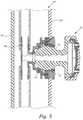
- FIG. 6is side cutaway view of a shower stall wall and side view of the supplemental showerhead illustrating a male threaded fastener affixing the supplemental showerhead to the shower stall sidewall;
- FIG. 7is side cutaway view of a shower stall wall and side view of the supplemental showerhead illustrating a hook and pile fastener affixing the supplemental showerhead to the shower stall sidewall;
- FIG. 8is side cutaway view of a shower stall wall and side view of the supplemental showerhead illustrating an adhesive fastener affixing the supplemental showerhead to the shower stall sidewall;
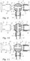
- FIG. 9is a side cutaway view of the diverter illustrating the valve rotated to allow water to flow from the diverter's inlet through the diverter's first and second outlets;
- FIG. 10is a side cutaway view of the diverter illustrating the valve rotated to allow water to flow from the diverter's inlet through the diverter's second outlet, but not first outlet;
- FIG. 11is a side cutaway view of the diverter illustrating the valve rotated to allow water to flow from the diverter's inlet through the diverter's first outlet, but not second outlet;
- FIG. 12is a perspective view of the showerhead assembly with a second preferred embodiment of supplemental showerhead mounted to a shower stall ceiling;
- FIG. 13is a perspective view of a housing for using with the second preferred supplemental showerhead illustrated in FIG. 12 ;
- FIG. 14is a side cutaway view of the housing for using with the second preferred supplemental showerhead illustrated in FIG. 12 .
- the showerhead assembly 1includes a diverter 5 , a primary showerhead 31 and a supplemental showerhead 65 .
- the diverter 5includes a housing 7 and a central cavity 9 .
- the diverterincludes a female threaded inlet 11 for permitting the inflow of water into the diverter's central cavity, as well as to the first outlet 13 and second outlet 15 .
- the diverter's inlet 11is female threaded and sized to mate to the male threads of a traditional pipe 95 which typically projects from a shower stall wall 93 .
- the diverter 5includes a valve assembly 17 within the diverter's central cavity 9 which selectively permits or obstructs the flow of water to the first outlet 13 and/or second outlet 15 .
- a preferred valve assembly 17includes a cylinder 21 within a cylindrically shaped central cavity 9 .
- This cylinderincludes channels 23 which can be rotated so as to obstruct the flow of water through the diverter 5 , or permit the flow of water to the first outlet 13 , second outlet 15 , or both.
- FIG. 9illustrates the valve assembly's cylinder 21 rotationally positioned so as to allow water received through inlet 11 to pass through the channels 23 to both the first outlet 13 and second outlet 15 . Meanwhile, FIG.
- FIG. 10illustrates the valve assembly's cylinder rotated, such as by the manual rotation of knob 19 , to a position where water is capable of flowing only to the second outlet 15 .
- FIG. 11illustrates the valve assembly's cylinder 21 rotated so that the channels are aligned to permit the passage of water from the inlet 11 only to the first outlet 13 , but not to the second outlet 15 .
- the primary showerhead 31preferably has a traditional construction known to those skilled in the art.
- the primary showerheadmay include nozzles which have a relatively simple and traditional circular orientation for providing a simply spray pattern.
- the primary showerheadmay incorporate more complex features (not shown) for providing selectable and controllable spray patterns.
- the primary showerhead 31may include a controller tab 93 for selectively controlling the flow of water such as to a central conduit 35 .
- the showerhead assembly's primary showerhead 31is connected to the diverter's first outlet 13 .
- the diverter's first outlet 13is longitudinally aligned with the diverter's inlet 11 so that the primary showerhead's face 32 is substantially orthogonal to the pipe 95 . (See FIGS. 1, 2 and 9-12 ).
- the primary showerhead 31is preferably connected to the diverter 5 by a ball joint connector 45 wherein the diverter's first outlet 33 includes a hollow ball extension 47 , and the proximal end 37 of the primary showerhead includes a socket receptacle 49 .
- the showerhead assembly 1includes at least one supplemental showerhead 65 .
- the showerhead assemblyincludes only a single supplemental showerhead 65 .
- the showerhead assemblymay include additional supplemental showerheads of the type described herein.
- the supplemental showerhead 65includes a housing 67 as well as a hollow passageway 69 within the housing 67 .
- the supplemental showerheadincludes one or more nozzles 71 positioned within, or connect to, the housing 67 . Each of the nozzles 71 are in fluid communication with the hollow passageway 69 .
- the nozzles 71are affixed within the housing 67 and connected to the passageway 69 by a ball and socket connection which permits the nozzles to pivot multidirectionally.
- the nozzles 71include a ball shaped proximal end 73 positioned within spherical socket 75 formed in the exterior wall of this housing 67 .
- each nozzle assemblyincludes an O-ring 77 providing a fluid-tight seal while allowing the nozzles 71 to pivot in a desired direction.
- These supplemental showerheads 65may include any number of nozzles 71 . However, in the preferred embodiment illustrated in FIGS. 1-8 , the supplemental showerhead 65 possesses three nozzles 71 .
- the supplemental showerhead 65possesses a housing 67 intended to be mounted to the shower stall ceiling. Furthermore, the supplemental showerhead 65 possesses an assembly which is substantially similar to a traditional showerhead including a plurality of nozzles 71 which project from a faceplate which has a relatively simple and traditional circular orientation for providing a simply spray pattern. The faceplate and nozzles are connected to the housing 67 by a ball connector 45 .
- the supplemental showerhead 65is connected to the diverter 5 by a hollow flexible hose 55 .
- the hollow flexible hoseincludes a female threaded first end and a female threaded second end.
- the flexible hose's first end 57is connected to the diverter's second outlet 15 which possesses a corresponding male threaded cylindrical construction.
- the flexible hose's second end 59connects to the supplemental showerhead's hollow passageway 69 which possesses a corresponding male threaded cylindrical inlet 70 .
- the showerhead assembly 1further includes a fastener 83 for affixing the supplemental showerhead 65 to the back wall 93 or ceiling 94 of a shower stall.
- the supplemental showerhead 65can be affixed in various positions such as vertically, as illustrated in FIG. 1 , or horizontally as illustrated in FIG. 2 .
- This fastenercan be of any type as can determined by one skilled in the art.
- the fastenerincludes one or more male threaded screws 85 which project through holes 86 in the supplemental showerhead's housing 67 to engage the shower stall wall 93 .
- the fastenermay comprise a hook and loop fastener construction 87 (see FIG. 7 ) or simple adhesive 89 (see FIG. 8 ).
- the fastenermay comprise one or more magnets incorporated into the supplemental showerhead's housing for affixing magnetically to metal affixed to or integrated into the shower stall wall 93 .
Landscapes
- Health & Medical Sciences (AREA)
- Public Health (AREA)
- Epidemiology (AREA)
- General Health & Medical Sciences (AREA)
- Nozzles (AREA)
Abstract
Description
Claims (10)
Priority Applications (2)
| Application Number | Priority Date | Filing Date | Title |
|---|---|---|---|
| US15/996,794US10568466B2 (en) | 2018-06-04 | 2018-06-04 | Showerhead assembly with supplemental wall mounted showerhead |
| US16/744,579US20200146512A1 (en) | 2018-06-04 | 2020-01-16 | Showerhead assembly with supplemental wall mounted showerhead |
Applications Claiming Priority (1)
| Application Number | Priority Date | Filing Date | Title |
|---|---|---|---|
| US15/996,794US10568466B2 (en) | 2018-06-04 | 2018-06-04 | Showerhead assembly with supplemental wall mounted showerhead |
Related Child Applications (1)
| Application Number | Title | Priority Date | Filing Date |
|---|---|---|---|
| US16/744,579ContinuationUS20200146512A1 (en) | 2018-06-04 | 2020-01-16 | Showerhead assembly with supplemental wall mounted showerhead |
Publications (2)
| Publication Number | Publication Date |
|---|---|
| US20190365160A1 US20190365160A1 (en) | 2019-12-05 |
| US10568466B2true US10568466B2 (en) | 2020-02-25 |
Family
ID=68694815
Family Applications (2)
| Application Number | Title | Priority Date | Filing Date |
|---|---|---|---|
| US15/996,794Active2038-06-20US10568466B2 (en) | 2018-06-04 | 2018-06-04 | Showerhead assembly with supplemental wall mounted showerhead |
| US16/744,579AbandonedUS20200146512A1 (en) | 2018-06-04 | 2020-01-16 | Showerhead assembly with supplemental wall mounted showerhead |
Family Applications After (1)
| Application Number | Title | Priority Date | Filing Date |
|---|---|---|---|
| US16/744,579AbandonedUS20200146512A1 (en) | 2018-06-04 | 2020-01-16 | Showerhead assembly with supplemental wall mounted showerhead |
Country Status (1)
| Country | Link |
|---|---|
| US (2) | US10568466B2 (en) |
Cited By (4)
| Publication number | Priority date | Publication date | Assignee | Title |
|---|---|---|---|---|
| US11758881B1 (en)* | 2021-07-02 | 2023-09-19 | Linda Priester Steeley | Pet bathing enclosure |
| US20240167256A1 (en)* | 2022-11-17 | 2024-05-23 | David M. DePasquale | On-demand cold water showerhead system |
| US12010776B2 (en) | 2019-12-20 | 2024-06-11 | Kohler Co. | Systems and methods for lighted showering |
| US20240399393A1 (en)* | 2023-06-05 | 2024-12-05 | Etl, Llc | Showerhead with adapter assembly |
Families Citing this family (16)
| Publication number | Priority date | Publication date | Assignee | Title |
|---|---|---|---|---|
| WO2021202925A1 (en)* | 2020-04-03 | 2021-10-07 | Kohler Co. | Digital rain showerhead |
| CN117797992A (en)* | 2020-09-14 | 2024-04-02 | 厦门松霖科技股份有限公司 | Lifting rod device with water outlet terminal and bathing device |
| CA203201S (en)* | 2020-11-06 | 2022-10-28 | Sinyu Tech Fujian Co Ltd | Shower head |
| USD987780S1 (en) | 2020-12-31 | 2023-05-30 | Kohler Co. | Handshower |
| USD1034903S1 (en) | 2020-12-31 | 2024-07-09 | Kohler, Co. | Handshower |
| USD962389S1 (en)* | 2021-02-22 | 2022-08-30 | Sinyu Technology (Fujian) Co., Ltd. | Shower head |
| USD977065S1 (en)* | 2021-05-05 | 2023-01-31 | Sinyu Technology (Fujian) Co., Ltd. | Shower head |
| USD994840S1 (en)* | 2021-07-14 | 2023-08-08 | Sinyu Technology (Fujian) Co., Ltd. | Spray heads for showers |
| USD999339S1 (en)* | 2021-07-14 | 2023-09-19 | Sinyu Technology (Fujian) Co., Ltd. | Spray heads for showers |
| USD1003390S1 (en)* | 2021-12-17 | 2023-10-31 | Delta Faucet Company | Shower filter housing |
| USD1050110S1 (en) | 2022-02-08 | 2024-11-05 | Boundless EC US LLC | Handheld shower nozzle |
| USD1031925S1 (en)* | 2022-08-24 | 2024-06-18 | Hansgrohe Se | Shower |
| USD1066573S1 (en)* | 2023-08-28 | 2025-03-11 | Xiamen Prime Shower Co., Ltd. | Shower |
| USD1039654S1 (en)* | 2023-09-14 | 2024-08-20 | Sinyu Technology (Fujian) Co., Ltd. | Spray head for shower |
| USD1059547S1 (en)* | 2024-02-02 | 2025-01-28 | Sanming Yilingliu E-Commerce Co., Ltd. | Shower head |
| USD1094643S1 (en)* | 2024-09-16 | 2025-09-23 | Shenzhen Kuxiang Shidai Technology Co., Ltd. | Shower head |
Citations (12)
| Publication number | Priority date | Publication date | Assignee | Title |
|---|---|---|---|---|
| US1120341A (en) | 1914-04-03 | 1914-12-08 | Waterbury Button Company | Self-winding device for eyeglass-cords and the like. |
| US3112073A (en)* | 1963-02-01 | 1963-11-26 | Clifford B Larson | Flexible spot rinsing head for shower baths |
| US3375532A (en)* | 1965-10-07 | 1968-04-02 | Gellmann Daniel | Flexible shower line unit |
| US3817247A (en) | 1972-11-20 | 1974-06-18 | M Mills | Portable douching device |
| US5093942A (en) | 1989-07-21 | 1992-03-10 | Harold Lang | Extendible and retractable spa jet |
| US5678258A (en) | 1995-09-29 | 1997-10-21 | Healy; Thomas K. | Multiple showerhead apparatus |
| US6415461B1 (en) | 2002-01-03 | 2002-07-09 | Niles H. Singer | Adjustable shower system |
| US20040237186A1 (en) | 2001-09-27 | 2004-12-02 | Petrovic John Edward | Add-on multi-head body spray shower |
| US7299510B2 (en)* | 2005-03-14 | 2007-11-27 | Pi Kuang Tsai | Holder device for shower head and nozzle |
| US20080185456A1 (en) | 2003-05-21 | 2008-08-07 | Mccabe Stephen Charles | Shower Apparatus |
| US9242259B2 (en) | 2013-01-17 | 2016-01-26 | Brian Jeronimus | Extendable shower head apparatus |
| US10232384B2 (en)* | 2017-03-07 | 2019-03-19 | Fan Fi International, Inc. | Showerhead assembly with retractable and extendable ancillary nozzles |
- 2018
- 2018-06-04USUS15/996,794patent/US10568466B2/enactiveActive
- 2020
- 2020-01-16USUS16/744,579patent/US20200146512A1/ennot_activeAbandoned
Patent Citations (12)
| Publication number | Priority date | Publication date | Assignee | Title |
|---|---|---|---|---|
| US1120341A (en) | 1914-04-03 | 1914-12-08 | Waterbury Button Company | Self-winding device for eyeglass-cords and the like. |
| US3112073A (en)* | 1963-02-01 | 1963-11-26 | Clifford B Larson | Flexible spot rinsing head for shower baths |
| US3375532A (en)* | 1965-10-07 | 1968-04-02 | Gellmann Daniel | Flexible shower line unit |
| US3817247A (en) | 1972-11-20 | 1974-06-18 | M Mills | Portable douching device |
| US5093942A (en) | 1989-07-21 | 1992-03-10 | Harold Lang | Extendible and retractable spa jet |
| US5678258A (en) | 1995-09-29 | 1997-10-21 | Healy; Thomas K. | Multiple showerhead apparatus |
| US20040237186A1 (en) | 2001-09-27 | 2004-12-02 | Petrovic John Edward | Add-on multi-head body spray shower |
| US6415461B1 (en) | 2002-01-03 | 2002-07-09 | Niles H. Singer | Adjustable shower system |
| US20080185456A1 (en) | 2003-05-21 | 2008-08-07 | Mccabe Stephen Charles | Shower Apparatus |
| US7299510B2 (en)* | 2005-03-14 | 2007-11-27 | Pi Kuang Tsai | Holder device for shower head and nozzle |
| US9242259B2 (en) | 2013-01-17 | 2016-01-26 | Brian Jeronimus | Extendable shower head apparatus |
| US10232384B2 (en)* | 2017-03-07 | 2019-03-19 | Fan Fi International, Inc. | Showerhead assembly with retractable and extendable ancillary nozzles |
Cited By (5)
| Publication number | Priority date | Publication date | Assignee | Title |
|---|---|---|---|---|
| US12010776B2 (en) | 2019-12-20 | 2024-06-11 | Kohler Co. | Systems and methods for lighted showering |
| US11758881B1 (en)* | 2021-07-02 | 2023-09-19 | Linda Priester Steeley | Pet bathing enclosure |
| US20240167256A1 (en)* | 2022-11-17 | 2024-05-23 | David M. DePasquale | On-demand cold water showerhead system |
| US12416140B2 (en)* | 2022-11-17 | 2025-09-16 | David M DePasquale | On-demand cold water showerhead system |
| US20240399393A1 (en)* | 2023-06-05 | 2024-12-05 | Etl, Llc | Showerhead with adapter assembly |
Also Published As
| Publication number | Publication date |
|---|---|
| US20200146512A1 (en) | 2020-05-14 |
| US20190365160A1 (en) | 2019-12-05 |
Similar Documents
| Publication | Publication Date | Title |
|---|---|---|
| US10568466B2 (en) | Showerhead assembly with supplemental wall mounted showerhead | |
| US20070022528A1 (en) | Combination handheld shower and stationary showerhead | |
| US11697127B2 (en) | Showerhead assembly with dual nozzle mount | |
| US9308540B2 (en) | Showerhead assembly with primary showerhead and orbiting showerhead | |
| US12043993B2 (en) | Ablutionary installation | |
| US4901927A (en) | Dual shower head assembly | |
| US10927531B2 (en) | Exposed hose faucet | |
| US5560548A (en) | Diverter valve for shower spray systems | |
| US5499767A (en) | Shower head having elongated arm, plural nozzles, and plural inlet lines | |
| US7458112B1 (en) | Shower assembly kit with multiple functions | |
| US4360160A (en) | Showerhead control adapter | |
| JP3231623U (en) | faucet | |
| US4394969A (en) | Showerhead control | |
| US10232384B2 (en) | Showerhead assembly with retractable and extendable ancillary nozzles | |
| US11761182B2 (en) | Dual showerhead assembly with ball joint connection | |
| US20050167625A1 (en) | Remotely controllable fluid control valve | |
| US20230175241A1 (en) | Combination handheld showerhead with positionable fixed showerhead | |
| US20070158470A1 (en) | Oxygenating showerhead | |
| US6449784B1 (en) | Easy operating diverter tub spout | |
| US7194775B2 (en) | Shower device with multiple movable arms | |
| KR20190020565A (en) | fluid flow conversion valve | |
| CN218933314U (en) | Shower system with operating handle | |
| US6935368B1 (en) | Cold-hot water faucet | |
| KR960013381B1 (en) | Device for body shower | |
| CN221097625U (en) | Four-function replaceable joint water outlet nozzle |
Legal Events
| Date | Code | Title | Description |
|---|---|---|---|
| AS | Assignment | Owner name:FAN FI INTERNATIONAL, INC., NEVADA Free format text:ASSIGNMENT OF ASSIGNORS INTEREST;ASSIGNOR:HAWKINS, TRAVIS;REEL/FRAME:045978/0234 Effective date:20180604 | |
| FEPP | Fee payment procedure | Free format text:ENTITY STATUS SET TO UNDISCOUNTED (ORIGINAL EVENT CODE: BIG.); ENTITY STATUS OF PATENT OWNER: SMALL ENTITY | |
| FEPP | Fee payment procedure | Free format text:ENTITY STATUS SET TO SMALL (ORIGINAL EVENT CODE: SMAL); ENTITY STATUS OF PATENT OWNER: SMALL ENTITY | |
| STPP | Information on status: patent application and granting procedure in general | Free format text:RESPONSE TO NON-FINAL OFFICE ACTION ENTERED AND FORWARDED TO EXAMINER | |
| AS | Assignment | Owner name:ETL, LLC, NEVADA Free format text:ASSIGNMENT OF ASSIGNORS INTEREST;ASSIGNOR:FAN FI INTERNATIONAL, INC.;REEL/FRAME:051437/0893 Effective date:20191218 | |
| STPP | Information on status: patent application and granting procedure in general | Free format text:PUBLICATIONS -- ISSUE FEE PAYMENT RECEIVED | |
| STPP | Information on status: patent application and granting procedure in general | Free format text:PUBLICATIONS -- ISSUE FEE PAYMENT VERIFIED | |
| STCF | Information on status: patent grant | Free format text:PATENTED CASE | |
| FEPP | Fee payment procedure | Free format text:MAINTENANCE FEE REMINDER MAILED (ORIGINAL EVENT CODE: REM.); ENTITY STATUS OF PATENT OWNER: SMALL ENTITY | |
| FEPP | Fee payment procedure | Free format text:SURCHARGE FOR LATE PAYMENT, SMALL ENTITY (ORIGINAL EVENT CODE: M2554); ENTITY STATUS OF PATENT OWNER: SMALL ENTITY | |
| MAFP | Maintenance fee payment | Free format text:PAYMENT OF MAINTENANCE FEE, 4TH YR, SMALL ENTITY (ORIGINAL EVENT CODE: M2551); ENTITY STATUS OF PATENT OWNER: SMALL ENTITY Year of fee payment:4 |