US10568453B2 - Coffee brewing device and coffee capsule machine having same - Google Patents
Coffee brewing device and coffee capsule machine having sameDownload PDFInfo
- Publication number
- US10568453B2 US10568453B2US15/303,887US201515303887AUS10568453B2US 10568453 B2US10568453 B2US 10568453B2US 201515303887 AUS201515303887 AUS 201515303887AUS 10568453 B2US10568453 B2US 10568453B2
- Authority
- US
- United States
- Prior art keywords
- capsule
- movable head
- head assembly
- coffee
- supporting plate
- Prior art date
- Legal status (The legal status is an assumption and is not a legal conclusion. Google has not performed a legal analysis and makes no representation as to the accuracy of the status listed.)
- Active, expires
Links
- 239000002775capsuleSubstances0.000titleclaimsabstractdescription143
- 230000007246mechanismEffects0.000claimsabstractdescription22
- 230000005540biological transmissionEffects0.000claimsabstractdescription11
- 239000002994raw materialSubstances0.000claimsdescription24
- 230000005484gravityEffects0.000description3
- 241000533293Sesbania emerusSpecies0.000description2
- 230000009471actionEffects0.000description2
- 238000006073displacement reactionMethods0.000description2
- 239000000843powderSubstances0.000description2
- 230000009286beneficial effectEffects0.000description1
- 235000013361beverageNutrition0.000description1
- 230000007547defectEffects0.000description1
- 239000011261inert gasSubstances0.000description1
- 238000000034methodMethods0.000description1
- 230000004048modificationEffects0.000description1
- 238000012986modificationMethods0.000description1
- 231100000252nontoxicToxicity0.000description1
- 230000003000nontoxic effectEffects0.000description1
- 238000002360preparation methodMethods0.000description1
- 230000008569processEffects0.000description1
- 238000007789sealingMethods0.000description1
- 238000004659sterilization and disinfectionMethods0.000description1
- 238000011282treatmentMethods0.000description1
Images


Classifications
- A—HUMAN NECESSITIES
- A47—FURNITURE; DOMESTIC ARTICLES OR APPLIANCES; COFFEE MILLS; SPICE MILLS; SUCTION CLEANERS IN GENERAL
- A47J—KITCHEN EQUIPMENT; COFFEE MILLS; SPICE MILLS; APPARATUS FOR MAKING BEVERAGES
- A47J31/00—Apparatus for making beverages
- A47J31/40—Beverage-making apparatus with dispensing means for adding a measured quantity of ingredients, e.g. coffee, water, sugar, cocoa, milk, tea
- A47J31/407—Beverage-making apparatus with dispensing means for adding a measured quantity of ingredients, e.g. coffee, water, sugar, cocoa, milk, tea with ingredient-containing cartridges; Cartridge-perforating means
- A—HUMAN NECESSITIES
- A47—FURNITURE; DOMESTIC ARTICLES OR APPLIANCES; COFFEE MILLS; SPICE MILLS; SUCTION CLEANERS IN GENERAL
- A47J—KITCHEN EQUIPMENT; COFFEE MILLS; SPICE MILLS; APPARATUS FOR MAKING BEVERAGES
- A47J31/00—Apparatus for making beverages
- A47J31/24—Coffee-making apparatus in which hot water is passed through the filter under pressure, i.e. in which the coffee grounds are extracted under pressure
- A47J31/34—Coffee-making apparatus in which hot water is passed through the filter under pressure, i.e. in which the coffee grounds are extracted under pressure with hot water under liquid pressure
- A47J31/36—Coffee-making apparatus in which hot water is passed through the filter under pressure, i.e. in which the coffee grounds are extracted under pressure with hot water under liquid pressure with mechanical pressure-producing means
- A47J31/3604—Coffee-making apparatus in which hot water is passed through the filter under pressure, i.e. in which the coffee grounds are extracted under pressure with hot water under liquid pressure with mechanical pressure-producing means with a mechanism arranged to move the brewing chamber between loading, infusing and ejecting stations
- A47J31/3623—Cartridges being employed
- A47J31/3633—Means to perform transfer from a loading position to an infusing position
- A—HUMAN NECESSITIES
- A47—FURNITURE; DOMESTIC ARTICLES OR APPLIANCES; COFFEE MILLS; SPICE MILLS; SUCTION CLEANERS IN GENERAL
- A47J—KITCHEN EQUIPMENT; COFFEE MILLS; SPICE MILLS; APPARATUS FOR MAKING BEVERAGES
- A47J31/00—Apparatus for making beverages
- A47J31/24—Coffee-making apparatus in which hot water is passed through the filter under pressure, i.e. in which the coffee grounds are extracted under pressure
- A47J31/34—Coffee-making apparatus in which hot water is passed through the filter under pressure, i.e. in which the coffee grounds are extracted under pressure with hot water under liquid pressure
- A47J31/36—Coffee-making apparatus in which hot water is passed through the filter under pressure, i.e. in which the coffee grounds are extracted under pressure with hot water under liquid pressure with mechanical pressure-producing means
- A47J31/3604—Coffee-making apparatus in which hot water is passed through the filter under pressure, i.e. in which the coffee grounds are extracted under pressure with hot water under liquid pressure with mechanical pressure-producing means with a mechanism arranged to move the brewing chamber between loading, infusing and ejecting stations
- A47J31/3623—Cartridges being employed
- A47J31/3638—Means to eject the cartridge after brewing
Definitions
- the present disclosurerelates to a beverage preparation device, more particularly, to a coffee brewing device and a coffee capsule machine having same.
- Coffee capsulesare produced by sealing the coffee powder, made by coffee beans subjected to special treatments, into capsules for the convenient use by consumers when brewing coffee, wherein nontoxic inert gas is filled in the capsules to prolong the shelf-life and for re-sterilization.
- coffee brewingcan be done simply by putting a coffee capsule into a dedicated coffee capsule machine, without the need of grinding coffee beans or filling coffee powders.
- the used capsulehas to be taken out of the brewing cavity by hand, the machine is inconvenient to operate and has low safety.
- an objective of the present disclosureis to provide a coffee brewing device which is convenient to operate and has high safety, and to provide a coffee capsule machine having same.
- a coffee brewing devicecomprising:
- a movable head assemblysaid movable head assembly is installed on said brewing support, and is capable of moving to-and-fro relative to said capsule holder assembly, a brewing cavity is formed between said movable head assembly and said capsule holder assembly;
- a driving deviceconfigured to drive said movable head assembly
- said automatic capsule-dropping mechanismcomprises a capsule supporting plate, a transmission mechanism and an elastic reset component; wherein, said capsule supporting plate is rotatably installed at a bottom of said capsule holder assembly via a rotating shaft, and said capsule supporting plate has a supporting position for holding a bottom of a raw-material capsule and a non-supporting position for leaving the bottom of said raw-material capsule hanging freely; said transmission mechanism is arranged between said capsule supporting plate and said movable head assembly, and is configured to drive said capsule supporting plate to rotate from said supporting position to said non-supporting position when said movable head assembly moves away from said capsule holder assembly; said elastic reset component is configured to drive said capsule supporting plate to rotate from said non-supporting position to said supporting position.
- an angle between said supporting position and said non-supporting positionis ranged from 90° to 120°.
- said transmission mechanismcomprises:
- ratchetis installed on said rotating shaft, and is configured to rotate with said capsule supporting plate synchronously, said ratchet has a plurality of first teeth at its outer circumference;
- a racksaid rack is installed on said movable head assembly, and is driven by said movable head assembly to move to-and-fro, said rack has a plurality of second teeth engageable with the plurality of first teeth; when said movable head assembly moves away from said capsule holder assembly, said second teeth and said first teeth get engaged and said ratchet is driven to rotate; when said movable head assembly moves towards said capsule holder assembly, said second teeth slides over said first teeth and said ratchet stops rotating.
- said rackhas a tooth segment approximate to said capsule holder assembly, and a non-tooth segment approximate to said movable head assembly, said second teeth are disposed on said tooth segment.
- a sliding grooveis disposed on said rack along the moving direction thereof, and said rack is installed on said movable head assembly via a pin passing through said sliding groove.
- the two ratchetsare located at two sides of said capsule supporting plate respectively, the two racks are located at two sides of said movable head assembly respectively.
- said capsule supporting plateis rigidly connected to said rotating shaft via a connector.
- said elastic reset componentis a torsion spring
- said torsion springis sleeved on said shaft, one end of said torsion spring is fixed on said capsule supporting plate, another end of said torsion spring is fixed on said capsule holder assembly.
- slots extending along a direction vertical to the moving direction of said movable head assemblyare disposed on both of opposed side walls of said brewing cavity respectively, a flange disposed at one end of said raw-material capsule approximate to said capsule holder assembly is inserted in said slots, and is slidable in the corresponding slots.
- the present disclosurefurther provides a coffee capsule machine, which comprises said coffee brewing device as set forth.
- the movable head assemblymoves away from the capsule holder assembly, and thus the capsule supporting plate is driven to rotate from the supporting position to the non-supporting position, thereby the raw-material capsule can automatically fall down by the gravity.
- the present inventionis convenient to operate and has high safety.
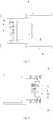
- FIG. 1is a schematic view illustrating the structure of the coffee brewing device according to one embodiment of the present invention
- FIG. 2is a schematic side view of the automatic capsule-dropping mechanism of the coffee brewing device shown in FIG. 1 ;
- FIG. 3is a schematic top view of the automatic capsule-dropping mechanism of the coffee brewing device shown in FIG. 1 ;
- FIG. 4is a schematic bottom view of the automatic capsule-dropping mechanism of the coffee brewing device shown in FIG. 1 ;
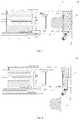
- FIG. 5is a schematic cross-section view illustrating the initial state of the coffee brewing device shown in FIG. 1 when a raw-material capsule is put into the brewing cavity;
- FIG. 6is a schematic cross-section view illustrating the brewing state of the coffee brewing device shown in FIG. 1 ;
- FIG. 7is a schematic cross-section view illustrating the brewed state of the coffee brewing device shown in FIG. 1 when the movable head assembly is moving back;
- FIG. 8is a schematic cross-section view illustrating the brewed state of the coffee brewing device shown in FIG. 1 when the raw-material capsule is being dropped off;
- FIG. 9is a schematic cross-section view illustrating the coffee brewing device shown in FIG. 1 when the device returns to its initial state after the coffee brewing has been completed.
- a coffee brewing device in one embodiment of the present inventionincludes a brewing support 10 , a capsule holder assembly 4 , a movable head assembly 1 , a driving device and an automatic capsule-dropping mechanism; wherein, the capsule holder assembly 4 is fixedly installed on the brewing support 10 ; the movable head assembly 1 is installed on the brewing support 10 , and is able to move to-and-fro relative to the capsule holder assembly 4 , a brewing cavity 3 is formed between the movable head assembly 1 and the capsule holder assembly 4 ; slots 17 extending along the direction vertical to the moving direction of the movable head assembly 1 are disposed on both of the opposed side walls of the brewing cavity 3 respectively.
- a raw-material capsule 2is put into the brewing cavity 3 , a flange 21 disposed at one end of the raw-material capsule 2 proximal to the capsule holder assembly 4 is inserted in the slots 17 and can slide in the corresponding slots 17 ;
- the driving deviceis configured to drive the movable head assembly 1 ; preferably, the driving device is a hydraulic driving device.
- the automatic capsule-dropping mechanismincludes a capsule supporting plate 5 , a transmission mechanism and an elastic reset component.
- the capsule supporting plate 5is rotatably installed at the bottom of the capsule holder assembly 4 via a rotating shaft 16 , and the capsule supporting plate 5 has a supporting position for holding the bottom of the raw-material capsule 2 and a non-supporting position for leaving the bottom of the raw-material capsule 2 hanging freely.
- the transmission mechanismis arranged between the capsule supporting plate 5 and the movable head assembly 1 , and is configured to drive the capsule supporting plate 5 to rotate from the supporting position to the non-supporting position when the movable head assembly 1 moves away from the capsule holder assembly 4 ; and then, after the capsule coffee brewing has been completed, the movable head assembly moves away from the capsule holder assembly, and the capsule supporting plate is driven to rotate from the supporting position to the non-supporting position, the raw-material capsule automatically falls down due to the gravity.
- the coffee brewing deviceis convenient to operate and has high safety.
- the elastic reset componentis configured to drive the capsule supporting plate 5 to rotate from the non-supporting position to the supporting position.
- the angle between the supporting position and the non-supporting positionis 90° ⁇ 120°.
- the transmission mechanismincludes two ratchets 7 and two racks 8 .
- the two ratchets 7are installed on the two ends of the rotating shaft 16 respectively, the ratchets 7 are installed on the rotating shaft 16 , and are configured to rotate with the capsule supporting plate 5 synchronously, each of the ratchets 7 has a plurality of first teeth 71 at its outer circumference.
- the two racks 8are located at the two sides of the movable head assembly 1 respectively, the racks 8 are installed on the movable head assembly 1 , and is driven by the movable head assembly 1 to move to-and-fro, each of the racks 8 has a plurality of second teeth 84 engageable with the plurality of first teeth 71 .
- the second teeth 84gets engaged with the first teeth 71 , and the ratchets 7 are driven to rotate; when the movable head assembly 1 moves towards the capsule holder assembly 4 , the second teeth 84 slides over the first teeth 71 and the ratchets 7 stop rotating.
- the rack 8has a tooth segment 81 approximate to the capsule holder assembly 4 and a non-tooth segment 82 approximate to the movable head assembly 1 , and the plurality of the second teeth 84 are disposed on the tooth segment 81 .
- the movable head assembly 1drives the racks 8 to move, and thus the ratchet 7 and the capsule supporting plate 5 are driven to rotate; when the displacement of the movable head assembly 1 from the capsule holder assembly 4 is larger than the length of the tooth segment 81 , the racks 8 are disengaged from the ratchets 7 , and the capsule supporting plate moves back to the supporting position by the action of the elastic reset component.
- a sliding groove 83is provided on the rack 8 along the moving direction thereof, and the rack 8 is installed on the movable head assembly 1 via a pin 9 passing through the sliding groove 83 . Therefore, when the movable head assembly 1 moves towards the capsule holder assembly 4 , firstly, the pin 9 slides through the sliding groove 83 , the racks 8 are still; only when the pin 9 has reached the rear end of the sliding groove 83 , the movable head assembly 1 will drive the racks 8 to move.
- the capsule supporting plate 5is rigidly connected to the rotating shaft 16 via a connector 15 .
- the elastic reset componentmay be a torsion spring 6 , the torsion spring 6 is sleeved on the rotating shaft 16 , and one end of the torsion spring 6 is fixed on the capsule supporting plate 5 , and the other end is fixed on the capsule holder assembly 4 .
- the coffee brewing device of this embodimentworks as follows:
- the movable head assembly 1is at the reset state, the capsule supporting plate 5 is at the supporting position, that is, the horizontal position.
- the raw-material capsuleis put into the brewing cavity of the coffee brewing device along the slots 17 on the capsule holder assembly 4 , and the raw-material capsule is supported by the capsule supporting plate 5 in the brewing cavity 3 (as shown in FIG. 5 ).
- the movable head assembly 1drives the racks 8 to move towards the capsule holder assembly 4 , and at this time, the bottom of the raw-material capsule 2 is supported by the capsule supporting plate 5 (as shown in FIG. 6 ).
- the capsule supporting plate 5rotates about the rotating shaft 16 by the ratchets 7 , until the capsule supporting plate rotates to a vertical position; during this process, the bottom of the raw-material capsule 2 is supported by the capsule supporting plate 5 .
- the movable head assembly 1drives the racks 8 to completely enter the capsule holder assembly 4 , the movable head assembly 1 continues moving towards the capsule holder assembly 4 until the raw-material capsule 2 is spiked and pressed completely (as shown in FIG. 7 ).
- the movable head assembly 1is driven by the driving device 1 to reset, and drives the racks 8 .
- the bottom of the raw-material capsule 2is still supported by the capsule supporting plate 5 , until the movable head assembly 1 drives the raw-material capsule 2 to be completely disengaged from the capsule holder assembly 4 .
- the capsule supporting plate 5is in the vertical position, hence, the bottom of raw-material capsule 2 is not supported, then the raw-material capsule 2 falls down from the brewing cavity due to the gravity, thereby the automatic capsule-dropping function can be achieved (as shown in FIG. 8 ).
- the capsule supporting plate 5can be automatically reset by the action of the torsion spring (as shown in FIG. 9 ).
- the coffee brewing device of the embodiments of the present inventionadopts the above technical solutions, the used capsule can be dropped automatically, and the device is convenient to operate and has a high safety.
- the present disclosurefurther provides a coffee capsule machine, comprising the coffee brewing device as set forth in the above embodiments.
Landscapes
- Engineering & Computer Science (AREA)
- Food Science & Technology (AREA)
- Mechanical Engineering (AREA)
- Apparatus For Making Beverages (AREA)
Abstract
Description
Claims (13)
Applications Claiming Priority (4)
| Application Number | Priority Date | Filing Date | Title |
|---|---|---|---|
| CN201410490631.6ACN105496197B (en) | 2014-09-23 | 2014-09-23 | Coffee brewing device and capsule coffee machine with same |
| CN201410490631.6 | 2014-09-23 | ||
| CN201410490631 | 2014-09-23 | ||
| PCT/CN2015/090272WO2016045576A1 (en) | 2014-09-23 | 2015-09-22 | Coffee making device and coffee capsule machine having same |
Publications (2)
| Publication Number | Publication Date |
|---|---|
| US20170245676A1 US20170245676A1 (en) | 2017-08-31 |
| US10568453B2true US10568453B2 (en) | 2020-02-25 |
Family
ID=55580315
Family Applications (1)
| Application Number | Title | Priority Date | Filing Date |
|---|---|---|---|
| US15/303,887Active2036-09-21US10568453B2 (en) | 2014-09-23 | 2015-09-22 | Coffee brewing device and coffee capsule machine having same |
Country Status (6)
| Country | Link |
|---|---|
| US (1) | US10568453B2 (en) |
| EP (1) | EP3199068B1 (en) |
| CN (1) | CN105496197B (en) |
| AU (1) | AU2015320127A1 (en) |
| CA (1) | CA2942931A1 (en) |
| WO (1) | WO2016045576A1 (en) |
Families Citing this family (13)
| Publication number | Priority date | Publication date | Assignee | Title |
|---|---|---|---|---|
| CN108078390B (en)* | 2018-01-19 | 2023-07-21 | 宁波锦宇电器有限公司 | Capsule coffee machine |
| CN209058843U (en)* | 2018-05-15 | 2019-07-05 | 广东力升电器有限公司 | A kind of capsule coffee-making device and its coffee machine |
| CN109662581B (en)* | 2019-01-25 | 2024-07-16 | 宁波佳音机电科技股份有限公司 | Capsule extraction mechanism and capsule coffee machine |
| CN111616595B (en)* | 2019-02-28 | 2021-08-06 | 广东美的生活电器制造有限公司 | Brewing device and beverage machine |
| WO2020173449A1 (en)* | 2019-02-28 | 2020-09-03 | 广东美的生活电器制造有限公司 | Brewing apparatus and beverage machine |
| CN110371331B (en)* | 2019-03-05 | 2025-03-25 | 遨想科创(深圳)有限公司 | Powder capsule making machine |
| CN110367823B (en)* | 2019-07-16 | 2024-08-02 | 深圳市西啡科技有限公司 | Brewing device and beverage machine |
| CN111870125A (en)* | 2020-07-15 | 2020-11-03 | 广州美咖科技有限公司 | A capsule receiving device |
| CN213216538U (en)* | 2020-07-29 | 2021-05-18 | 广东百胜图科技有限公司 | Coffee brewing system and coffee machine |
| CN113576256A (en)* | 2021-07-07 | 2021-11-02 | 六安索伊电器制造有限公司 | Self-service coffee vending machine with radio frequency identification function |
| CN113317683B (en)* | 2021-07-14 | 2024-02-27 | 上海环讯实业有限公司 | Coffee machine handle |
| CN113712434B (en)* | 2021-08-23 | 2023-09-15 | 深圳安吉尔饮水产业集团有限公司 | Beverage capsule mechanism and beverage preparation system |
| CN115381293A (en)* | 2022-09-29 | 2022-11-25 | 珠海横琴鑫润智能制造有限公司 | Capsule beverage brewing device and capsule beverage brewing method |
Citations (11)
| Publication number | Priority date | Publication date | Assignee | Title |
|---|---|---|---|---|
| US5755149A (en)* | 1993-12-20 | 1998-05-26 | Compagnie Mediterraneenne Des Cafes S.A. | Automatic machine for the preparation of hot beverage infusions |
| US5776527A (en)* | 1993-09-06 | 1998-07-07 | Compagnie Mediterraneene Des Cafes S.A. | Package of ground coffee of the prefilled tablet type and espresso coffee machine using such a package |
| US5974949A (en)* | 1997-02-18 | 1999-11-02 | Eldom Rothrist Ag | Espresso machine |
| EP1532904A1 (en) | 2003-11-20 | 2005-05-25 | Steiner AG Weggis | Coffee machine |
| US20090007794A1 (en)* | 2004-06-04 | 2009-01-08 | Virginio Cortese | Percolator Machine for Making a Beverage |
| CN101491415A (en) | 2009-03-04 | 2009-07-29 | 广东新宝电器股份有限公司 | Coffee capsule machine |
| CN201987328U (en) | 2011-01-31 | 2011-09-28 | 苏州工业园区咖乐美电器有限公司 | Manual capsule coffee machine |
| CN201987327U (en) | 2010-12-27 | 2011-09-28 | 苏州工业园区咖乐美电器有限公司 | Manual capsule coffee machine |
| CN203280250U (en) | 2013-04-08 | 2013-11-13 | 广东德豪润达电气股份有限公司 | Beverage making device |
| WO2014132158A1 (en) | 2013-03-01 | 2014-09-04 | Bialetti Industrie S.P.A. | Infusion device for the production of a hot drink |
| CN204192367U (en) | 2014-09-23 | 2015-03-11 | 广东德豪润达电气股份有限公司 | Coffee brewing device and capsule coffee machine having same |
Family Cites Families (5)
| Publication number | Priority date | Publication date | Assignee | Title |
|---|---|---|---|---|
| ITMI20050854A1 (en)* | 2005-05-12 | 2006-11-13 | Perfect Steam Appliances Ltd | INFUSION GROUP FOR DRINK PREPARATION MACHINES |
| CN201061463Y (en)* | 2007-07-23 | 2008-05-21 | 王冬雷 | Device for preparing hot beverage |
| RU2589576C2 (en)* | 2010-08-13 | 2016-07-10 | Конинклейке Филипс Электроникс Н.В. | Brewing device for food product preparation |
| CN201822642U (en)* | 2010-09-20 | 2011-05-11 | 宁波贝仕迪电器有限公司 | Rubber bag type coffee machine |
| CN103417115B (en)* | 2013-07-31 | 2015-12-23 | 广东新宝电器股份有限公司 | Capsule type coffee machine |
- 2014
- 2014-09-23CNCN201410490631.6Apatent/CN105496197B/enactiveActive
- 2015
- 2015-09-22EPEP15845334.0Apatent/EP3199068B1/ennot_activeNot-in-force
- 2015-09-22AUAU2015320127Apatent/AU2015320127A1/ennot_activeAbandoned
- 2015-09-22WOPCT/CN2015/090272patent/WO2016045576A1/enactiveApplication Filing
- 2015-09-22CACA2942931Apatent/CA2942931A1/ennot_activeAbandoned
- 2015-09-22USUS15/303,887patent/US10568453B2/enactiveActive
Patent Citations (11)
| Publication number | Priority date | Publication date | Assignee | Title |
|---|---|---|---|---|
| US5776527A (en)* | 1993-09-06 | 1998-07-07 | Compagnie Mediterraneene Des Cafes S.A. | Package of ground coffee of the prefilled tablet type and espresso coffee machine using such a package |
| US5755149A (en)* | 1993-12-20 | 1998-05-26 | Compagnie Mediterraneenne Des Cafes S.A. | Automatic machine for the preparation of hot beverage infusions |
| US5974949A (en)* | 1997-02-18 | 1999-11-02 | Eldom Rothrist Ag | Espresso machine |
| EP1532904A1 (en) | 2003-11-20 | 2005-05-25 | Steiner AG Weggis | Coffee machine |
| US20090007794A1 (en)* | 2004-06-04 | 2009-01-08 | Virginio Cortese | Percolator Machine for Making a Beverage |
| CN101491415A (en) | 2009-03-04 | 2009-07-29 | 广东新宝电器股份有限公司 | Coffee capsule machine |
| CN201987327U (en) | 2010-12-27 | 2011-09-28 | 苏州工业园区咖乐美电器有限公司 | Manual capsule coffee machine |
| CN201987328U (en) | 2011-01-31 | 2011-09-28 | 苏州工业园区咖乐美电器有限公司 | Manual capsule coffee machine |
| WO2014132158A1 (en) | 2013-03-01 | 2014-09-04 | Bialetti Industrie S.P.A. | Infusion device for the production of a hot drink |
| CN203280250U (en) | 2013-04-08 | 2013-11-13 | 广东德豪润达电气股份有限公司 | Beverage making device |
| CN204192367U (en) | 2014-09-23 | 2015-03-11 | 广东德豪润达电气股份有限公司 | Coffee brewing device and capsule coffee machine having same |
Also Published As
| Publication number | Publication date |
|---|---|
| AU2015320127A1 (en) | 2016-10-06 |
| CN105496197A (en) | 2016-04-20 |
| EP3199068A1 (en) | 2017-08-02 |
| EP3199068B1 (en) | 2018-11-14 |
| WO2016045576A1 (en) | 2016-03-31 |
| CN105496197B (en) | 2018-06-26 |
| US20170245676A1 (en) | 2017-08-31 |
| EP3199068A4 (en) | 2017-09-20 |
| CA2942931A1 (en) | 2016-03-31 |
Similar Documents
| Publication | Publication Date | Title |
|---|---|---|
| US10568453B2 (en) | Coffee brewing device and coffee capsule machine having same | |
| AU2015261074B2 (en) | Beverage brewing unit particularly for machines for preparing beverages from capsules | |
| CN102159121B (en) | Brewing equipment for coffee machines etc. | |
| EP2621317B1 (en) | Device and method for retrieving a capsule from a beverage production apparatus | |
| EP2242406B1 (en) | Machine for dispensing infusions from a pod preparation having a resetting device | |
| KR102218870B1 (en) | Brewing module | |
| ITMI20110876A1 (en) | INFUSER GROUP, PARTICULARLY FOR CAPSULES AND / OR PODS FOR OBTAINING INFUSED AND SIMILAR DRINKS. | |
| EP2792282B1 (en) | Apparatus for dispensing coffee and the like | |
| BRPI0713632B1 (en) | INFUSION UNIT | |
| EP3141166B1 (en) | Beverage brewing device allowing beverage capsule to be removed easily | |
| ES2358208T3 (en) | APPARATUS FOR PREPARING AND DISPENSING DRINKS FROM POWDER CONTAINED IN CAPSULES. | |
| CN103989407A (en) | Bag feeding and bag taking-off mechanism of beverage making device | |
| US10568451B2 (en) | Dispensing assembly for machines for preparing liquid products by means of capsules | |
| CN203539114U (en) | Capsule falling device of beverage dispenser | |
| AU2011212106A1 (en) | Machine for the preparation of a beverage | |
| CN204192367U (en) | Coffee brewing device and capsule coffee machine having same | |
| RU149607U1 (en) | MECHANISM OF STORAGE AND DELIVERY OF GOODS FOR A VENDOR | |
| HK1145078B (en) | Improvements in or relating to beverage preparation machines | |
| HK1145078A1 (en) | Improvements in or relating to beverage preparation machines |
Legal Events
| Date | Code | Title | Description |
|---|---|---|---|
| AS | Assignment | Owner name:ELEC-TECH INTERNATIONAL CO., LTD., CHINA Free format text:ASSIGNMENT OF ASSIGNORS INTEREST;ASSIGNORS:WANG, DONGLEI;SHU, YUNWEI;REEL/FRAME:040874/0531 Effective date:20160914 | |
| STPP | Information on status: patent application and granting procedure in general | Free format text:DOCKETED NEW CASE - READY FOR EXAMINATION | |
| STPP | Information on status: patent application and granting procedure in general | Free format text:NON FINAL ACTION MAILED | |
| STPP | Information on status: patent application and granting procedure in general | Free format text:RESPONSE TO NON-FINAL OFFICE ACTION ENTERED AND FORWARDED TO EXAMINER | |
| STPP | Information on status: patent application and granting procedure in general | Free format text:NOTICE OF ALLOWANCE MAILED -- APPLICATION RECEIVED IN OFFICE OF PUBLICATIONS | |
| AS | Assignment | Owner name:LUMILEDS LLC, CALIFORNIA Free format text:LIEN;ASSIGNOR:ELEC-TECH INTERNATIONAL CO., LTD.;REEL/FRAME:051312/0882 Effective date:20191206 | |
| STPP | Information on status: patent application and granting procedure in general | Free format text:AWAITING TC RESP., ISSUE FEE NOT PAID | |
| STPP | Information on status: patent application and granting procedure in general | Free format text:PUBLICATIONS -- ISSUE FEE PAYMENT VERIFIED | |
| STCF | Information on status: patent grant | Free format text:PATENTED CASE | |
| MAFP | Maintenance fee payment | Free format text:PAYMENT OF MAINTENANCE FEE, 4TH YEAR, LARGE ENTITY (ORIGINAL EVENT CODE: M1551); ENTITY STATUS OF PATENT OWNER: LARGE ENTITY Year of fee payment:4 |