US10567024B2 - Electronic device case with sealed liquid-containing chamber and heterogeneous liquid mixture display - Google Patents
Electronic device case with sealed liquid-containing chamber and heterogeneous liquid mixture displayDownload PDFInfo
- Publication number
- US10567024B2 US10567024B2US15/997,456US201815997456AUS10567024B2US 10567024 B2US10567024 B2US 10567024B2US 201815997456 AUS201815997456 AUS 201815997456AUS 10567024 B2US10567024 B2US 10567024B2
- Authority
- US
- United States
- Prior art keywords
- case
- liquid
- chamber
- electronic device
- shell
- Prior art date
- Legal status (The legal status is an assumption and is not a legal conclusion. Google has not performed a legal analysis and makes no representation as to the accuracy of the status listed.)
- Active
Links
Images


Classifications
- G—PHYSICS
- G06—COMPUTING OR CALCULATING; COUNTING
- G06F—ELECTRIC DIGITAL DATA PROCESSING
- G06F1/00—Details not covered by groups G06F3/00 - G06F13/00 and G06F21/00
- G06F1/16—Constructional details or arrangements
- G06F1/1613—Constructional details or arrangements for portable computers
- G06F1/1633—Constructional details or arrangements of portable computers not specific to the type of enclosures covered by groups G06F1/1615 - G06F1/1626
- G06F1/1656—Details related to functional adaptations of the enclosure, e.g. to provide protection against EMI, shock, water, or to host detachable peripherals like a mouse or removable expansions units like PCMCIA cards, or to provide access to internal components for maintenance or to removable storage supports like CDs or DVDs, or to mechanically mount accessories
- H—ELECTRICITY
- H04—ELECTRIC COMMUNICATION TECHNIQUE
- H04B—TRANSMISSION
- H04B1/00—Details of transmission systems, not covered by a single one of groups H04B3/00 - H04B13/00; Details of transmission systems not characterised by the medium used for transmission
- H04B1/38—Transceivers, i.e. devices in which transmitter and receiver form a structural unit and in which at least one part is used for functions of transmitting and receiving
- H04B1/3827—Portable transceivers
- H04B1/3888—Arrangements for carrying or protecting transceivers
- H—ELECTRICITY
- H04—ELECTRIC COMMUNICATION TECHNIQUE
- H04M—TELEPHONIC COMMUNICATION
- H04M1/00—Substation equipment, e.g. for use by subscribers
- H04M1/02—Constructional features of telephone sets
- H04M1/0202—Portable telephone sets, e.g. cordless phones, mobile phones or bar type handsets
- H—ELECTRICITY
- H04—ELECTRIC COMMUNICATION TECHNIQUE
- H04M—TELEPHONIC COMMUNICATION
- H04M1/00—Substation equipment, e.g. for use by subscribers
- H04M1/02—Constructional features of telephone sets
- H04M1/0202—Portable telephone sets, e.g. cordless phones, mobile phones or bar type handsets
- H04M1/0279—Improving the user comfort or ergonomics
- H04M1/0283—Improving the user comfort or ergonomics for providing a decorative aspect, e.g. customization of casings, exchangeable faceplate
- H—ELECTRICITY
- H04—ELECTRIC COMMUNICATION TECHNIQUE
- H04M—TELEPHONIC COMMUNICATION
- H04M1/00—Substation equipment, e.g. for use by subscribers
- H04M1/02—Constructional features of telephone sets
- H04M1/18—Telephone sets specially adapted for use in ships, mines, or other places exposed to adverse environment
- H04M1/185—Improving the shock resistance of the housing, e.g. by increasing the rigidity
- A—HUMAN NECESSITIES
- A45—HAND OR TRAVELLING ARTICLES
- A45C—PURSES; LUGGAGE; HAND CARRIED BAGS
- A45C11/00—Receptacles for purposes not provided for in groups A45C1/00-A45C9/00
- A45C11/002—Receptacles for purposes not provided for in groups A45C1/00-A45C9/00 for storing portable handheld communication devices, e.g. pagers or smart phones
Definitions
- the present inventionrelates generally to the field of protective cases or covers for cell phones and other electronic devices, and more particularly to a protective and/or decorative case having one or more hermetically sealed liquid filled chambers with an ultrasonically welded joint on the inside of the plastic main back shell, and optionally one or more additional sealed liquid filled chambers visible from an external vantage point, with one or more liquid display materials contained within the case chamber(s).
- Cases and covers for mobile phones, tablet computers and other handheld electronic devicesmay include ornamental decorative elements or visual display features.
- cell phone casesmay include a chamber containing liquid and glitter or sparkling elements that cascade down through the liquid and are visible externally through a transparent cover portion of the case.
- the hard plastic coveris ultrasonically welded to the hard or soft plastic main back shell on the outside. This exposes the delicate ultrasonic welding joint to outside forces like pressure, drop impact, etc., leading to frequent breakage and leakage of the contents of the sealed liquid filled chamber.
- Such casescan be prone to leaking of the liquid from the chamber, and needs exist for improved cases and improved methods for manufacturing such cases that reduce the incidence of leaking. It is to the provision of a case or cover for an electronic device meeting these and other needs that the present invention is primarily directed.
- the present inventionprovides improved cases or covers for electronic devices, and improved methods for manufacturing such cases.
- Cases according to example embodiments of the inventioninclude a chamber containing liquid and glitter or sparkling elements that cascade down through the liquid and are visible externally through a transparent portion of the case, with an improved sealing arrangement to prevent or reduce the incidence of leaking of the liquid from the chamber.
- the present inventionrelates to a decorative cell-phone or other electronic device case or cover with a hermetically sealed liquid filled chamber with an ultrasonically welded joint on the inside of the plastic main back shell to prevent leakage of material from the chamber.
- the inventionrelates to a method for manufacturing such a case or cover, and for forming a hermetically sealed liquid filled chamber in or on a cell-phone or other electronic device case or cover with improved sealing characteristics and leak resistance.
- the inventionrelates to a case for an electronic device.
- the casepreferably includes a shell defining an interior space for receiving the electronic device.
- the shellpreferably includes a chamber having a liquid contained within the chamber, and a transparent portion through which the liquid is visible from external of the case.
- a sealis preferably formed around the chamber to contain the liquid therein, the seal being located within the interior space of the shell.
- the inventionin another aspect, relates to a case for an electronic device, the case preferably including a back shell comprising a back panel and at least one sidewall extending from the back panel. At least a portion of the back panel is preferably transparent, and the back shell preferably defines an internal recess.
- the casepreferably also includes an inner cover configured to extend over the internal recess of the back shell to form a chamber between the back shell and the inner cover.
- a liquidis preferably contained within the chamber formed between the back shell and the inner cover and is visible through the transparent portion of the back panel from an external vantage point.
- the liquidis preferably sealed within the chamber by a continuous seal formed between the back shell and the inner cover around the internal recess of the back shell.
- the inventionin another aspect, relates to a case for an electronic device, the case preferably including a back shell having a back panel, and at least a portion of the back panel being transparent.
- the back shellpreferably defines an internal recess.
- the casepreferably also includes an inner cover configured to extend over the internal recess of the back shell to form a chamber between the back shell and the inner cover.
- a liquidis preferably contained within the chamber and is visible through the transparent portion of the back panel from an external vantage point.
- the liquidis preferably sealed within the chamber by a seal located internally within the case.
- the inventionin another aspect, relates to a method of fabricating a case for an electronic device.
- the methodpreferably includes the steps of providing a back shell having a transparent back panel and an internal recess, installing an inner cover over the internal recess, forming a seal internally within the case between the inner cover and the back shell around the internal recess to define an enclosed chamber, introducing a liquid and decorative elements into the enclosed chamber through a fill hole, and closing the fill hole with a stopper.
- the inventionin another aspect, relates to a multi-chambered case for an electronic device, wherein each of a plurality of sealed chambers contains a first liquid component and a second liquid component that is immiscible with the first liquid component.
- FIGS. 1A, 1B and 1Cshow a case or cover for a cell-phone or other electronic device according to an example embodiment of the invention, in different orientations showing a cascading movement of decorative elements through a liquid within a sealed chamber and visible through a transparent portion of the case.
- FIG. 2is an assembly view of the case or cover of FIG. 1 .
- FIG. 3is a plan view of the inside of the case or cover of FIG. 1 .
- FIGS. 4A and 4Bshow cross-sectional views of a seal portion of the case or cover according to an example form of the invention, taken along cut line 4 A- 4 A in FIG. 3 , and showing formation of the seal ( FIG. 4A ) and the final formed seal arrangement ( FIG. 4B ).
- FIG. 5is a perspective view of the case or cover of FIG. 1 , showing installation of a stopper.
- FIG. 6is a detailed view of the stopper of FIG. 5 , according to an example form of the invention.
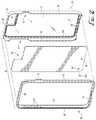
- FIGS. 7A and 7Bshow a case or cover for a cell-phone or other electronic device according to another example embodiment of the invention, having multiple sealed liquid filled chambers.
- FIG. 8shows a cross-sectional view of the multi-chambered case shown in FIG. 7 .
- FIG. 9shows an assembly view of the multi-chambered case shown in FIG. 7 .
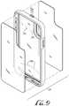
- FIG. 10shows an assembly view of the case shell of a multi-chambered electronic device case according to another example embodiment of the invention.
- FIG. 11is a perspective view in partial cross-section showing heterogeneous mixtures of immiscible display liquids contained in each of the chambers of the electronic device case shown in FIG. 10 .
- FIG. 12is a detailed cross-sectional assembly view showing formation of the seals of the chambers of the electronic device case shown in FIG. 10 .
- FIGS. 13A and 13Bshow front and back views of the case shell of the electronic device case shown in FIG. 10 .
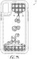
- FIG. 14shows a fill sequence process of filling each of the chambers of the electronic device case shown in FIG. 10 with different heterogeneous mixtures of immiscible display liquids to create a changing multi-colored visual display effect.
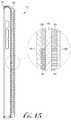
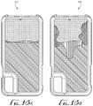
- FIG. 15is a cross-sectional view of the electronic device case shown in FIG. 10 , with the display chambers of the case filled with different heterogeneous mixtures of immiscible display liquids.
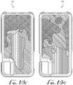
- FIGS. 16A-16Eshow a sequence of liquid flows of the display liquids within the display chambers upon inversion of the case of FIG. 10 .
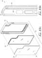
- FIGS. 17A and 17Bshow a case or cover for a cell-phone or other electronic device according to an example embodiment of the invention.
- FIGS. 18A and 18Bshow a case or cover for a cell-phone or other electronic device according to an example embodiment of the invention.
- FIGS. 1-6show example embodiments of a case or cover 10 for a cell-phone, smart phone, tablet computer or other portable handheld electronic device D, and steps of a method for manufacturing such a case or cover, according to example embodiments of the present invention.
- the hard plastic coveris ultrasonically welded to the hard or soft plastic main back shell on the inside, greatly reducing probability of breakage as compared to previously known cases wherein the hard plastic cover is ultrasonically welded to the hard or soft plastic main back shell on the outside.
- FIGS. 1-6show details of the case 10 according to an example embodiment of the invention.
- the case 10comprises a hard or soft plastic main back shell 20 having a back panel 22 at least partially comprising one or more transparent portions, one or more sidewall portions extending from the back panel.
- first and second sidewall portions 24 , 26 , a top panel 28 , and a bottom panel 30extend generally perpendicular and forward from the back panel 22 .
- the back panel 22 and peripheral walls 24 , 26 , 28 , 30thus define an interior receiver space for receiving and housing the device D.
- one or more cutout sections 34are provided along one or more of these peripheral walls to allow access to controls, speakers, microphones or other features of the electronic device D when the case 10 is installed onto the device.
- the back paneloptionally comprises a camera cutout 36 formed therein for accommodating camera and flash elements of the device D.
- the main back shell 20is formed from polycarbonate, polyethylene, polyurethane or other material(s).
- the case 10optionally also comprises a soft plastic bumper 50 configured to fit within the periphery of the back shell 20 , to securely but removably retain the device D within the case while in use.
- the bumper 50 and peripheral walls of the back shelloptionally include cooperating engagement features such as interengaging projections and recesses formed therein or thereon, to provide a detachable coupling of the elements with the electronic device D sandwiched therebetween.
- the bumper 50comprises a generally rectangular frame with a central opening formed therein, and is molded from thermoplastic polyurethane (TPU) or other resilient and compressible material.
- TPUthermoplastic polyurethane
- the bumper 50comprises first and second sidewalls 52 , 54 , a top panel 56 and a bottom panel 58 , configured to fit closely within corresponding peripheral walls of the back shell 20 .
- the bumper 50optionally comprises one or more outwardly projecting portions, for example incorporating actuator buttons 62 or other features, and positioned and configured to be received within corresponding cutout portions 34 of the peripheral walls of the back shell 20 and align with control features or other elements of the electronic device D when the case 10 is assembled.
- the bumper 50optionally also comprises one or more openings allowing communication therethrough, and in alignment with speakers, microphones and/or other user interface portions of the device D when installed and in use.
- An outwardly and/or inwardly projecting flange or lip 66is optionally provided along the front edge of the bumper for engagement with the peripheral walls of the back shell 20 and with the device D when assembled.
- the casefurther comprises a hard plastic inner cover 80 , configured to fit within the back shell 20 , along the inside face of the back panel 22 .
- the inner cover 80is optionally transparent, whereby branding information such as logo L or other features of the electronic device D are visible from an external vantage point, through back shell 20 and inner cover 80 of the case.
- the inner cover 80optionally also includes a recess or cutout section 82 configured to accommodate the camera and flash of the device D.
- a hole or opening 88is provided through the inner cover to permit filling of the liquid filled chamber, as described further below.
- the inner cover 80is formed from polycarbonate, polyethylene, polyurethane or other material(s).
- a continuously and hermetically sealed chamberis formed between the inside of the back shell 20 and the inner cover 80 .
- an interior recess 100can be provided in the back shell, on its front or inner surface (i.e., adjacent the space within which the electronic device D is received into the case 10 ) to define an open space or void forming the chamber.
- the back shell 20comprises a raised surface or shoulder 102 extending continuously around the recess 100 to provide a sealing surface arranged along the inside periphery of the back shell and spaced a small distance inwardly from the peripheral walls of the back shell.
- a thin fin or flangeprojects forward from the shoulder 100 forming an energy director joint or boss 108 , to form a seal 112 between the back shell 20 and the inner cover 80 .
- the seal 112forms a continuous band completely surrounding a bounded space within the inside periphery of the case 10 , to enclose and hermetically seal the chamber 100 formed between the back shell 20 and the inner cover 80 . Because the seal 112 is located within the interior of the case 10 , between the device D and the back panel 22 , it is less susceptible to contact and potential breach of the seal when the case is in use.
- the seal 112is formed by ultrasonic welding, by pressing the inner cover 80 against the raised boss or energy director joint 108 of the back shell 20 . Ultrasonic energy is applied in combination with the application of pressure to melt the material of the energy director joint 108 and fuse the inner cover 80 with the shoulder 102 of the back shell, with the melted material of the energy director joint forming a butt joint making the seal 112 .
- the sealmay be formed by thermal welding, solvent bonding, adhesive, one or more sealing members, or other sealing means.
- a liquid 120such as for example mineral oil or water
- decorative elements 122such as for example metallic glitter or beads
- at least a portion of the liquid 120 and/or the decorative elements 122can include one or more fluorescent, phosphorescent or luminescent (i.e., glow-in-the-dark) materials, particles and/or elements.
- the fill hole 88is closed or sealed, for example by insertion of a soft plastic stopper 140 , as shown in FIGS. 5 and 6 .
- the stopper 140is formed from a thermoplastic elastomer or other soft plastic material suitable for compression fit and sealing within the fill hole 88 , and has a smaller inner portion 142 and a flared or expanded outer portion 144 .
- the userplaces the soft plastic bumper 50 around their phone or other electronic device D, and inserts the phone and bumper into the back shell 20 , securing the device in the case 10 .
- the device Dis then used in typical fashion, with the case 10 protecting the device and providing an aesthetically appealing appearance.
- the decorative elements 122cascade downwardly under influence of gravity through the liquid 120 , providing an entertaining motion effect visible through the transparent back panel 22 from an external vantage point behind the case (i.e., opposite the device D).
- the seal 112 containing the liquid 120 and decorative elements 122 within the sealed chamber 100is located internally within the case 10 , it is less susceptible to contact and potential damage which might result in leakage of the liquid from the chamber than would be the case with an external seal. Also, in some embodiments the back of the device D housed within the case 10 may be held in contact against the inner cover 80 , optionally applying compression to the seal 112 , further improving the seals integrity.
- FIGS. 7-9show a case or cover 110 for an electronic device according to another example embodiment.
- the case 110includes an inner sealed chamber 140 and an outer sealed chamber 170 .
- Each of the chambers 140 , 170can be partially or substantially fully filled with one or more liquid components, for example a lower density first liquid component and a higher density second liquid component.
- the first and second liquid componentsare of different color or appearance, for example the first liquid component being substantially clear or transparent, and the second liquid component being colored; or alternatively being of contrasting colors.
- a substantially transparent wall 190divides and separates the two chambers 140 , 170 , allowing external visibility of the contents of both chambers.
- the inner sealed chamber 140is configured in substantially similar fashion to the above described embodiment.
- a fill spout or other sealable openingmay be provided in fluid communication with each of the chambers 140 , 170 to deliver the respective liquid components therein.
- one or more obliquely angled flanges or flow-directing weirs 210are provided within one or both of the chambers 140 , 170 to direct the flow of the liquid component(s) contained therein, for enhanced visual effect.
- two opposed pairs of inversely angled flanges or flow-directing weirs 210each pair having a space between them, respectively funnel and disperse the flow of liquid in a first flow direction, and disperse and funnel the flow in an opposite second flow direction when the case 110 is inverted. While the depicted embodiment includes two sealed liquid filled chambers, in alternative embodiments, three or more sealed liquid filled chambers may be included at one or more portions of the case, in various multiple chamber or multi-chamber case configurations.
- FIGS. 10-16show a case or cover 310 for an electronic device, according another example embodiment of the invention.
- the case 310generally comprises a polycarbonate (PC) or other impact-resistant hard plastic shell 320 , a thermoplastic polyurethane (TPU) or other impact-resistant soft or resilient plastic bumper or liner 340 , a first or inner polycarbonate or other hard plastic liquid display plate or panel 350 , a second or outer polycarbonate or other hard plastic liquid display plate or panel 360 , and one or more actuator button inserts 370 configured for engagement within corresponding cutouts in the liner and shell and for operative engagement with corresponding buttons or control features of the electronic device to be used with the case or cover 310 .
- PCpolycarbonate
- TPUthermoplastic polyurethane
- the liner 340is optionally configured to be permanently or removably retained within the shell 320 and hold a mobile phone or other electronic device within the case 310 .
- the outer liquid display panel 360is preferably transparent or tinted translucent to allow visual observation of the contents from a vantage point external of the back of the case 310 ; and the inner liquid display panel 350 is preferably opaque white or other light color, or alternatively a transparent or tinted translucent material.
- provision of an opaque white or other light color inner display panel 350helps to provide greater visual contrast with the colors of the contents of the display chambers when the case is used on a device with a dark colored back surface.
- the shell 320comprises a chamber separation wall 322 , forming a liquid impermeable barrier between an inner liquid chamber 324 and an outer liquid chamber 326 .
- the inner liquid chamberdefines a generally rectangular recess in the front or inside of the shell 320
- the outer liquid chamberdefines a generally rectangular recess in the back or outside of the shell 320 .
- the shell 320further comprises top, bottom, left and right sidewalls extending forward from the chamber separation wall, to define the receiver for the electronic device to be held in the case 310 .
- the chamber separation wall 322is preferably transparent or tinted translucent.
- a first continuous and hermetic, liquid impervious sealis formed around the inner liquid chamber 324 , between an inner flange of the shell 320 and the inner liquid display panel 350 ; and a second continuous and hermetic, liquid impervious seal is formed around the outer liquid chamber 326 , between an outer flange of the shell 320 and the outer liquid display panel 360 .
- a first energy director joint or bossprojects forward from the inner flange of the shell 320 , and extends continuously around the inner liquid chamber 324 , to form the seal between the shell and the inner panel 350 ; and a second energy director joint or boss projects rearward from the outer flange of the shell, and extends continuously around the outer liquid chamber 326 , to form the seal between the shell and the outer panel 360 .
- the sealsare formed by ultrasonic welding, by pressing the inner panel 350 against the inner flange of the shell 320 and pressing the outer panel 360 against the outer flange of the shell.
- Ultrasonic energyis applied in combination with the application of pressure to melt the material of the energy director joints and fuse the inner inner and outer panels 350 , 360 with the inner and outer flanges of the shell, with the melted material of the energy director joint forming a butt joint making the seal.
- the sealsmay be formed by thermal welding, solvent bonding, adhesive, one or more sealing members, or other sealing means.
- an outer lip 330is formed on the shell 320 around the outer chamber 326 , having a depth approximately equal to the thickness of the outer panel 360 , to form a smooth and continuous transition without a noticeable seam between the back of the shell and the outer panel, to resist detachment of the outer seal and reduce the likelihood of leakage from the outer chamber 326 .
- the inner seal between the shell 320 and the inner panel 350is shielded within the case, between the shell and the housed electronic device, to resist detachment of the inner seal and reduce the likelihood of leakage from the inner chamber 324 .
- the chamber separation wall 322optionally includes one or more obliquely angled flanges or flow-directing weirs 332 along its interior and/or exterior face(s) to direct the flow of the liquid component(s) contained one or both of the chambers 324 , 326 , for enhanced visual effect.
- oppositely inclined offset pairs of flow-directing elementsform one or more V-shaped channels within the chambers.
- angled flanges or flow-directing weirsmay be provided along interior faces of the inner and/or outer panels 350 , 360 , and/or otherwise configured flow-directing features can be provided for varying visual effects.
- First and second fill spouts or ports 380 , 382may be provided in fluid communication with the inner and outer chambers 324 , 326 , respectively, for delivering liquid display contents into the chambers.
- the fill spouts or portsmay optionally be sealed shut by plugs or other sealing or closure means after filling to prevent liquid discharge.
- the fill ports or spoutscan be positioned adjacent the top, bottom or either side of the case, or alternatively can be formed through the inner and/or outer panels 350 , 360 .
- each chamber 324 , 326contains an immiscible mixture of a dyed high-density solution and a dyed low-density solution of differing colors.
- the two carriers in each chamberare specially selected so that they are immiscible with each other.
- the two dyes in each chamberare also specially selected so that they are immiscible with each other but miscible with their respective carriers.
- the colorscan be opaque, translucent or transparent. The overlaying of multiple colors due to the multiple chamber design gives the illusion of multiple colors in the cell phone case.
- the first or inner chamber 324contains a first liquid component 390 and a second liquid component 392 that is immiscible with the first liquid component.
- the first liquid 390 componentcomprises a first carrier liquid and a first dye that is miscible with the first carrier liquid.
- the second liquid component 392comprises a second carrier liquid and a second dye that is miscible with the second carrier liquid.
- the first carrier liquidis immiscible with the second carrier liquid
- the first dyeis immiscible with the second dye.
- the first dyehas a first color
- the second dyehas a second color that is different than the first color.
- the second or outer chamber 326contains a third liquid component 394 and a fourth liquid component 396 that is immiscible with the third liquid component.
- the third liquid component 394comprises a third carrier liquid and a third dye that is miscible with the third carrier liquid.
- the fourth liquid component 396comprises a fourth carrier liquid and a fourth dye that is miscible with the fourth carrier liquid.
- the third carrier liquidis immiscible with the fourth carrier liquid, and the third dye is immiscible with the fourth dye.
- the third dyehas a third color that is preferably different from the first and second colors, and the fourth dye has a fourth color that is preferably different than the first, second and third colors.
- the first liquid component 390comprises a first carrier comprising a low density liquid such as mineral oil, silicone oil or other low density liquid, and a first dye such as an oil soluble dye of a first color, for example pink;
- the second liquid component 392comprises a second carrier comprising a high density liquid such as a water and propylene glycol solution, and a second dye such as a water soluble dye of a second (different) color, for example blue;
- the third liquid component 394comprises a third carrier comprising a low density liquid such as mineral oil, silicone oil or other low density liquid, and a third dye such as an oil soluble dye of a third (still different) color, for example green;
- the fourth liquid component 396comprises a fourth carrier comprising a high density liquid such as a water and propylene glycol solution, and a fourth dye such as a water soluble dye of a fourth (and further still different) color, for example purple.
- one or more solid componentssuch as, for example, metallic or
- inversion of movement of the case 310causes flows and counterflows between the liquids contained in the chambers 324 , 326 , producing varied and constantly changing appearances with patterns and sections of multiple different colors, which are visible through the back of the case.
- the liquid contents of the outer chamber 326overlie the liquid contents of the inner chamber 324 , creating the appearance of different flow patterns and color combinations, with the contents of both the inner and outer chambers being visible through the back panel of the case through the transparent or translucent outer panel 360 and the transparent or translucent chamber separation wall 322 .
- FIGS. 16A, 16B, 16C, 16D and 16Eshow various stages of liquid flow and liquid display.
- the casefurther comprises one or more light sources configured to direct light into or onto the liquid-containing chambers of the case for enhanced visual effect.
- FIGS. 17A and 17Bshow a case or cover 410 for a cell phone or other electronic device according to another example embodiment of the invention.
- the shell of the casecomprises a single layer overmolded construction defining two chambers for containment of fluid contents in substantially similar fashion to those described above.
- An outer frame 420 formed of a thermoplastic polyurethane (TPU) or other impact-resistant soft or resilient plasticis overmolded onto a medial back insert panel 440 formed of polycarbonate (PC) or other impact-resistant hard plastic.
- TPUthermoplastic polyurethane
- PCpolycarbonate
- An anterior or inner liquid display containment panel 450is sealingly attached to a peripheral inner sealing face of the medial panel 440 to form a first or inner liquid containment chamber therebetween; and a posterior or outer liquid display containment panel 460 is sealingly attached to a peripheral outer sealing face of the medial panel 440 to form a second or outer liquid containment chamber therebetween.
- One or more liquid componentsare dispensed to at least partially fill the inner and outer liquid containment chambers in substantially similar fashion as described above.
- the medial panel 440 and the outer containment panel 460are at least partially, and optionally substantially entirely, transparent or translucent to allow visual observation of the fluid(s) contained in the inner and outer liquid containment chambers from the back side of the case 410 .
- the inner containment panel 450is substantially opaque, for example white or other light color, for enhanced color contrast of the liquid contents of the inner and outer chambers; or alternatively may be transparent or translucent to allow visualization of the back of the housed electronic device through the case.
- FIGS. 18A and 18Bshow a case or cover 510 for a cell phone or other electronic device according to another example embodiment of the invention.
- the shell of the casecomprises a single layer overmolded construction defining a single chamber for containment of fluid contents in substantially similar fashion as described above.
- An outer frame 520 formed of a thermoplastic polyurethane (TPU) or other impact-resistant soft or resilient plasticis overmolded onto a back insert panel 540 formed of polycarbonate (PC) or other impact-resistant hard plastic.
- An inner liquid display containment panel 550is sealingly attached to a peripheral inner sealing face of the back panel 540 to form a liquid containment chamber therebetween.
- One or more liquid componentsare delivered to at least partially fill the liquid containment chamber in substantially similar fashion as described above.
- the back panel 540is at least partially, and optionally substantially entirely, transparent or translucent to allow visual observation of the fluid(s) contained in the liquid containment chamber from the back side of the case 510 .
- the inner containment panel 550is substantially opaque, for example white or other light color, for enhanced color contrast of the liquid contents of the liquid containment chamber; or alternatively may be transparent or translucent to allow visualization of the back of the housed electronic device through the case.
Landscapes
- Engineering & Computer Science (AREA)
- Signal Processing (AREA)
- Computer Hardware Design (AREA)
- General Engineering & Computer Science (AREA)
- Theoretical Computer Science (AREA)
- Human Computer Interaction (AREA)
- Physics & Mathematics (AREA)
- General Physics & Mathematics (AREA)
- Computer Networks & Wireless Communication (AREA)
- Casings For Electric Apparatus (AREA)
- Packages (AREA)
- Telephone Set Structure (AREA)
Abstract
Description
Claims (5)
Priority Applications (1)
| Application Number | Priority Date | Filing Date | Title |
|---|---|---|---|
| US15/997,456US10567024B2 (en) | 2017-07-10 | 2018-06-04 | Electronic device case with sealed liquid-containing chamber and heterogeneous liquid mixture display |
Applications Claiming Priority (4)
| Application Number | Priority Date | Filing Date | Title |
|---|---|---|---|
| US201762530373P | 2017-07-10 | 2017-07-10 | |
| US201762568050P | 2017-10-04 | 2017-10-04 | |
| US201862678217P | 2018-05-30 | 2018-05-30 | |
| US15/997,456US10567024B2 (en) | 2017-07-10 | 2018-06-04 | Electronic device case with sealed liquid-containing chamber and heterogeneous liquid mixture display |
Publications (2)
| Publication Number | Publication Date |
|---|---|
| US20190013832A1 US20190013832A1 (en) | 2019-01-10 |
| US10567024B2true US10567024B2 (en) | 2020-02-18 |
Family
ID=62713117
Family Applications (1)
| Application Number | Title | Priority Date | Filing Date |
|---|---|---|---|
| US15/997,456ActiveUS10567024B2 (en) | 2017-07-10 | 2018-06-04 | Electronic device case with sealed liquid-containing chamber and heterogeneous liquid mixture display |
Country Status (2)
| Country | Link |
|---|---|
| US (1) | US10567024B2 (en) |
| WO (1) | WO2019013903A1 (en) |
Families Citing this family (29)
| Publication number | Priority date | Publication date | Assignee | Title |
|---|---|---|---|---|
| US20180065780A1 (en)* | 2016-09-06 | 2018-03-08 | Samsonite Ip Holdings S.Àr.L. | Case with internal graphic |
| KR102613168B1 (en)* | 2017-01-04 | 2023-12-14 | 삼성전자 주식회사 | Cover accessory and electronic device using the same |
| US10694825B2 (en)* | 2017-09-08 | 2020-06-30 | Samsonite Ip Holdings S.Àr.L. | Tri-layer case with shock-absorbing impact geometry |
| USD889452S1 (en) | 2017-09-08 | 2020-07-07 | Samsonite Ip Holdings S.Àr.L. | Case for an electronic device |
| US10743630B2 (en) | 2017-09-08 | 2020-08-18 | Samsonite Ip Holdings S.Àr.L. | Dual-layer bumper for a case for a mobile device |
| WO2019135904A1 (en)* | 2018-01-08 | 2019-07-11 | Popsockets Llc | Case for a mobile electronic device |
| US10708403B2 (en)* | 2018-07-23 | 2020-07-07 | Case-Mate, Inc. | Electronic device case with a transparent or translucent back panel |
| USD940122S1 (en) | 2018-08-24 | 2022-01-04 | Speculative Product Design, Llc | Case for mobile electronic communications device |
| USD981998S1 (en)* | 2018-10-07 | 2023-03-28 | YSP Tech, Inc. | Phone case |
| USD908120S1 (en)* | 2019-08-30 | 2021-01-19 | Dongguan Yuetao Plastic Electronics Technology Co., Ltd. | Mobile phone protective case |
| US11522571B2 (en) | 2019-10-28 | 2022-12-06 | Speculative Product Design, Llc | Mobile device case with bonded soft resin insert and shell |
| USD949138S1 (en) | 2020-06-19 | 2022-04-19 | Speculative Product Design, Llc | Case for an electronic communications device |
| USD917451S1 (en)* | 2020-06-25 | 2021-04-27 | Mosnovo Sdn.Bhd | Phone case |
| CN111787732B (en)* | 2020-07-01 | 2022-05-20 | Oppo广东移动通信有限公司 | Electronic equipment shell, manufacturing method thereof and electronic equipment |
| USD961568S1 (en)* | 2020-08-10 | 2022-08-23 | Samsung Electronics Co., Ltd. | Electronic device |
| USD966249S1 (en) | 2020-08-10 | 2022-10-11 | Samsung Electronics Co., Ltd. | Electronic device |
| USD961570S1 (en)* | 2020-08-10 | 2022-08-23 | Samsung Electronics Co., Ltd. | Electronic device |
| USD961541S1 (en)* | 2020-08-10 | 2022-08-23 | Samsung Electronics Co., Ltd. | Electronic device |
| USD961569S1 (en)* | 2020-08-10 | 2022-08-23 | Samsung Electronics Co., Ltd. | Electronic device |
| USD961571S1 (en)* | 2020-08-10 | 2022-08-23 | Samsung Electronics Co., Ltd. | Electronic device |
| USD966251S1 (en)* | 2020-08-10 | 2022-10-11 | Samsung Electronics Co., Ltd. | Electronic device |
| USD970461S1 (en)* | 2020-08-10 | 2022-11-22 | Samsung Electronics Co., Ltd. | Electronic device |
| USD966250S1 (en) | 2020-08-10 | 2022-10-11 | Samsung Electronics Co., Ltd. | Electronic device |
| USD961542S1 (en)* | 2020-08-10 | 2022-08-23 | Samsung Electronics Co., Ltd. | Electronic device |
| USD998580S1 (en)* | 2021-06-04 | 2023-09-12 | Samsung Electronics Co., Ltd. | Electronic device |
| CN115955795A (en)* | 2021-07-15 | 2023-04-11 | Oppo广东移动通信有限公司 | Decorative components, housing components and electronic equipment |
| US11949242B1 (en)* | 2023-06-20 | 2024-04-02 | Ping Liao | Wireless charger with flowing display effect |
| CN117956057A (en)* | 2024-01-25 | 2024-04-30 | 深圳市艺色科技有限公司 | A mobile terminal protective shell for diving |
| US12310473B1 (en)* | 2025-02-21 | 2025-05-27 | Hanglei Wu | Luminescent earphone compartment |
Citations (52)
| Publication number | Priority date | Publication date | Assignee | Title |
|---|---|---|---|---|
| US2361423A (en) | 1941-09-20 | 1944-10-31 | Sarah S Snyder | Crystal novelty |
| US5175873A (en) | 1990-12-24 | 1992-12-29 | Motorola, Inc. | Water resistant selective call receiver |
| US5520775A (en)* | 1994-02-25 | 1996-05-28 | Motorola, Inc. | Energy director for ultrasonic weld joint |
| US6471056B1 (en) | 2001-07-06 | 2002-10-29 | Kuo-Chen Tzeng | Portable electronic device protective cover |
| US20030002876A1 (en) | 2001-06-27 | 2003-01-02 | Baron John M. | Fluid-filled bodies for portable devices |
| US20030223947A1 (en)* | 2002-05-31 | 2003-12-04 | Mattel, Inc. | Multi-phased immiscible liquid composition for toy articles |
| US20040128876A1 (en)* | 2002-07-19 | 2004-07-08 | Maria Cheek | Greeting cards, postcards, gift bags, and the like employing a special effects container |
| US6792709B1 (en) | 2001-08-24 | 2004-09-21 | Neil Enterprises, Inc. | Display device |
| US20060172765A1 (en)* | 2005-01-29 | 2006-08-03 | Yosef Lev | Gel filled mobile phone case |
| US7158376B2 (en) | 2001-11-19 | 2007-01-02 | Otter Products, Llc | Protective enclosure for an interactive flat-panel controlled device |
| USD582149S1 (en) | 2008-02-19 | 2008-12-09 | Incase Designs Corporation | Portable electronic device case |
| US7555325B2 (en) | 2001-11-03 | 2009-06-30 | Jean Goros | Protective sleeve for small portable electronic devices |
| US7594576B2 (en) | 2004-11-12 | 2009-09-29 | Hong Fu Jin Precision Industry (Shenzhen) Co., Ltd. | PDA carrying device |
| USD600908S1 (en) | 2008-11-26 | 2009-09-29 | Otter Products, Llc | Case |
| US7609512B2 (en) | 2001-11-19 | 2009-10-27 | Otter Products, Llc | Protective enclosure for electronic device |
| US20100048267A1 (en) | 2008-08-19 | 2010-02-25 | Beyond Electronics Inc. | Disposable protector case for cell phone with touchable lens to be used with a touchscreen cell phone |
| USD613282S1 (en) | 2007-09-10 | 2010-04-06 | Otter Products, Llc | Phone case |
| USD615536S1 (en) | 2009-09-25 | 2010-05-11 | Otter Products, Llc | Case |
| USD615535S1 (en) | 2009-06-19 | 2010-05-11 | Otter Products, Llc | Case |
| USD617785S1 (en) | 2009-10-02 | 2010-06-15 | Otter Products, Llc | Case |
| USD617784S1 (en) | 2008-11-26 | 2010-06-15 | Otter Products, Llc | Case |
| USD619574S1 (en) | 2009-08-21 | 2010-07-13 | Otter Products, Llc | Case |
| US20100270189A1 (en) | 2006-03-02 | 2010-10-28 | Zagg, Inc. | Protective covering with a customizable image for an electronic device |
| USD634741S1 (en) | 2010-08-26 | 2011-03-22 | Otter Products, Llc | Case |
| USD636386S1 (en) | 2010-06-14 | 2011-04-19 | Otter Products, Llc | Case |
| US7933122B2 (en) | 2007-06-06 | 2011-04-26 | Otter Products, Llc | Protective enclosure for a computer |
| USD638005S1 (en) | 2010-06-14 | 2011-05-17 | Otter Products, Llc | Case |
| USD641013S1 (en) | 2010-06-14 | 2011-07-05 | Otter Products, Llc | Case |
| USD642170S1 (en) | 2010-10-19 | 2011-07-26 | Otter Products, Llc | Cover for an electronic device component |
| US20110183790A1 (en)* | 2010-01-23 | 2011-07-28 | Chernick Mark J | High Bounce Ball Having Encapsulated Free-Moving Core |
| US20110192510A1 (en)* | 2010-02-10 | 2011-08-11 | Switcheasy Limited | Protective casing portable handheld electronic device |
| US20110192743A1 (en) | 2010-02-08 | 2011-08-11 | May Derek M | Shock Absorber For Portable Devices |
| CN201985941U (en) | 2011-02-11 | 2011-09-21 | 上海闻泰电子科技有限公司 | Mobile phone case with water flow effect |
| US8051980B2 (en) | 2007-11-02 | 2011-11-08 | Hong Fu Jin Precision Industry (Shenzhen) Co., Ltd. | Protective sleeve for portable electronic devices |
| USD651203S1 (en) | 2010-09-21 | 2011-12-27 | Otter Products, Llc | Case |
| US20120031914A1 (en) | 2010-08-04 | 2012-02-09 | Liu qing-ping | Protecting case for a mobile phone |
| US20120055826A1 (en) | 2006-09-22 | 2012-03-08 | Nissha Printing Co., Ltd. | Housing Case, Method for Manufacturing Housing Case, and Glass Insert Molding Die Used in Same |
| US20120103844A1 (en) | 2010-10-26 | 2012-05-03 | Marware, Inc. | Mobile telephone or portable digital media player case having interchangeable panels |
| US8204561B2 (en) | 2009-02-06 | 2012-06-19 | Speculative Product Design, Llc | One piece co-formed exterior hard shell case with an elastomeric liner for mobile electronic devices |
| US8245842B2 (en) | 2008-06-27 | 2012-08-21 | Switcheasy Limited | Protective case having a hybrid structure for portable handheld electronic devices |
| US8320597B2 (en) | 2009-01-22 | 2012-11-27 | Griffin Technology, Inc. | Acoustic dock for portable electronic device |
| US20120305422A1 (en) | 2011-06-01 | 2012-12-06 | Scosche Industries, Inc. | Portable device protector case |
| US20130034836A1 (en)* | 2011-08-01 | 2013-02-07 | Stefanie Marshall | Systems, Devices, and/or Methods for Handheld Devices |
| US8430240B2 (en) | 2010-07-26 | 2013-04-30 | Spigen Sgp Co., Ltd. | Case for bar type mobile electronic device |
| US8453835B2 (en) | 2010-06-24 | 2013-06-04 | Kar Ming So | Protective cover for communication device |
| US8695798B2 (en) | 2012-01-09 | 2014-04-15 | Case-Mate, Inc. | Case for electronic devices |
| US8777002B2 (en) | 2010-08-10 | 2014-07-15 | Shark-Eye Llc | Protective case with substantially-rigid outer layer and cushioning inner layer |
| USD723531S1 (en) | 2013-01-17 | 2015-03-03 | Broadscope International Inc. | Phone case with display chamber |
| US20150141090A1 (en)* | 2013-11-19 | 2015-05-21 | Great Performance Industries Co., Ltd. | Mobilephone casing |
| US20160013821A1 (en)* | 2013-09-13 | 2016-01-14 | Qualcomm Incorporated | Apparatus and method for fast local oscillator re-tune for residual side band reduction |
| US20160182113A1 (en)* | 2014-12-17 | 2016-06-23 | Asia Vital Components Co., Ltd. | Protective device capable of dissipating heat |
| USD773448S1 (en) | 2015-08-18 | 2016-12-06 | Dennis Armillotti | Glow-in-the-dark phone case |
- 2018
- 2018-06-04USUS15/997,456patent/US10567024B2/enactiveActive
- 2018-06-04WOPCT/US2018/035885patent/WO2019013903A1/ennot_activeCeased
Patent Citations (53)
| Publication number | Priority date | Publication date | Assignee | Title |
|---|---|---|---|---|
| US2361423A (en) | 1941-09-20 | 1944-10-31 | Sarah S Snyder | Crystal novelty |
| US5175873A (en) | 1990-12-24 | 1992-12-29 | Motorola, Inc. | Water resistant selective call receiver |
| US5520775A (en)* | 1994-02-25 | 1996-05-28 | Motorola, Inc. | Energy director for ultrasonic weld joint |
| US20030002876A1 (en) | 2001-06-27 | 2003-01-02 | Baron John M. | Fluid-filled bodies for portable devices |
| US6471056B1 (en) | 2001-07-06 | 2002-10-29 | Kuo-Chen Tzeng | Portable electronic device protective cover |
| US6792709B1 (en) | 2001-08-24 | 2004-09-21 | Neil Enterprises, Inc. | Display device |
| US7555325B2 (en) | 2001-11-03 | 2009-06-30 | Jean Goros | Protective sleeve for small portable electronic devices |
| US7158376B2 (en) | 2001-11-19 | 2007-01-02 | Otter Products, Llc | Protective enclosure for an interactive flat-panel controlled device |
| US7609512B2 (en) | 2001-11-19 | 2009-10-27 | Otter Products, Llc | Protective enclosure for electronic device |
| US20030223947A1 (en)* | 2002-05-31 | 2003-12-04 | Mattel, Inc. | Multi-phased immiscible liquid composition for toy articles |
| US20040128876A1 (en)* | 2002-07-19 | 2004-07-08 | Maria Cheek | Greeting cards, postcards, gift bags, and the like employing a special effects container |
| US7594576B2 (en) | 2004-11-12 | 2009-09-29 | Hong Fu Jin Precision Industry (Shenzhen) Co., Ltd. | PDA carrying device |
| US20060172765A1 (en)* | 2005-01-29 | 2006-08-03 | Yosef Lev | Gel filled mobile phone case |
| US20100270189A1 (en) | 2006-03-02 | 2010-10-28 | Zagg, Inc. | Protective covering with a customizable image for an electronic device |
| US20120055826A1 (en) | 2006-09-22 | 2012-03-08 | Nissha Printing Co., Ltd. | Housing Case, Method for Manufacturing Housing Case, and Glass Insert Molding Die Used in Same |
| US7933122B2 (en) | 2007-06-06 | 2011-04-26 | Otter Products, Llc | Protective enclosure for a computer |
| USD613282S1 (en) | 2007-09-10 | 2010-04-06 | Otter Products, Llc | Phone case |
| US8051980B2 (en) | 2007-11-02 | 2011-11-08 | Hong Fu Jin Precision Industry (Shenzhen) Co., Ltd. | Protective sleeve for portable electronic devices |
| USD582149S1 (en) | 2008-02-19 | 2008-12-09 | Incase Designs Corporation | Portable electronic device case |
| US8245842B2 (en) | 2008-06-27 | 2012-08-21 | Switcheasy Limited | Protective case having a hybrid structure for portable handheld electronic devices |
| US20100048267A1 (en) | 2008-08-19 | 2010-02-25 | Beyond Electronics Inc. | Disposable protector case for cell phone with touchable lens to be used with a touchscreen cell phone |
| USD617784S1 (en) | 2008-11-26 | 2010-06-15 | Otter Products, Llc | Case |
| USD600908S1 (en) | 2008-11-26 | 2009-09-29 | Otter Products, Llc | Case |
| US8320597B2 (en) | 2009-01-22 | 2012-11-27 | Griffin Technology, Inc. | Acoustic dock for portable electronic device |
| US8204561B2 (en) | 2009-02-06 | 2012-06-19 | Speculative Product Design, Llc | One piece co-formed exterior hard shell case with an elastomeric liner for mobile electronic devices |
| USD615535S1 (en) | 2009-06-19 | 2010-05-11 | Otter Products, Llc | Case |
| USD619574S1 (en) | 2009-08-21 | 2010-07-13 | Otter Products, Llc | Case |
| USD615536S1 (en) | 2009-09-25 | 2010-05-11 | Otter Products, Llc | Case |
| USD617785S1 (en) | 2009-10-02 | 2010-06-15 | Otter Products, Llc | Case |
| US20110183790A1 (en)* | 2010-01-23 | 2011-07-28 | Chernick Mark J | High Bounce Ball Having Encapsulated Free-Moving Core |
| US20110192743A1 (en) | 2010-02-08 | 2011-08-11 | May Derek M | Shock Absorber For Portable Devices |
| US20110192510A1 (en)* | 2010-02-10 | 2011-08-11 | Switcheasy Limited | Protective casing portable handheld electronic device |
| USD636386S1 (en) | 2010-06-14 | 2011-04-19 | Otter Products, Llc | Case |
| USD641013S1 (en) | 2010-06-14 | 2011-07-05 | Otter Products, Llc | Case |
| USD638005S1 (en) | 2010-06-14 | 2011-05-17 | Otter Products, Llc | Case |
| US8453835B2 (en) | 2010-06-24 | 2013-06-04 | Kar Ming So | Protective cover for communication device |
| US8430240B2 (en) | 2010-07-26 | 2013-04-30 | Spigen Sgp Co., Ltd. | Case for bar type mobile electronic device |
| US20120031914A1 (en) | 2010-08-04 | 2012-02-09 | Liu qing-ping | Protecting case for a mobile phone |
| US8777002B2 (en) | 2010-08-10 | 2014-07-15 | Shark-Eye Llc | Protective case with substantially-rigid outer layer and cushioning inner layer |
| USD634741S1 (en) | 2010-08-26 | 2011-03-22 | Otter Products, Llc | Case |
| USD651203S1 (en) | 2010-09-21 | 2011-12-27 | Otter Products, Llc | Case |
| USD642170S1 (en) | 2010-10-19 | 2011-07-26 | Otter Products, Llc | Cover for an electronic device component |
| US20120103844A1 (en) | 2010-10-26 | 2012-05-03 | Marware, Inc. | Mobile telephone or portable digital media player case having interchangeable panels |
| CN201985941U (en) | 2011-02-11 | 2011-09-21 | 上海闻泰电子科技有限公司 | Mobile phone case with water flow effect |
| US20120305422A1 (en) | 2011-06-01 | 2012-12-06 | Scosche Industries, Inc. | Portable device protector case |
| US20130034836A1 (en)* | 2011-08-01 | 2013-02-07 | Stefanie Marshall | Systems, Devices, and/or Methods for Handheld Devices |
| US8695798B2 (en) | 2012-01-09 | 2014-04-15 | Case-Mate, Inc. | Case for electronic devices |
| US20140224675A1 (en) | 2012-01-09 | 2014-08-14 | Case-Mate, Inc. | Case for electronic devices |
| USD723531S1 (en) | 2013-01-17 | 2015-03-03 | Broadscope International Inc. | Phone case with display chamber |
| US20160013821A1 (en)* | 2013-09-13 | 2016-01-14 | Qualcomm Incorporated | Apparatus and method for fast local oscillator re-tune for residual side band reduction |
| US20150141090A1 (en)* | 2013-11-19 | 2015-05-21 | Great Performance Industries Co., Ltd. | Mobilephone casing |
| US20160182113A1 (en)* | 2014-12-17 | 2016-06-23 | Asia Vital Components Co., Ltd. | Protective device capable of dissipating heat |
| USD773448S1 (en) | 2015-08-18 | 2016-12-06 | Dennis Armillotti | Glow-in-the-dark phone case |
Non-Patent Citations (4)
| Title |
|---|
| Fire Frost Tech, "iPhone 7 Case Mate Waterfall Naked Tough Clear Case", youtube, Sep. 18, 2016, p. 3, Retrieved from the Internet:URL: https://www.youtube.com/watch?v=nNaFSUIHdyA [retrieved on Jul. 24, 2018]. |
| International Search Report and Written Opinion for PCT/US2013/020749; dated Apr. 5, 2013; 9 pgs. |
| International Search Report and Written Opinion for PCT/US2018/035885; dated Aug. 1, 2018; 16 pgs. |
| Stiegman, "Glitter Liquid Phone Cases Are Leaking and Giving People Severe Burns," Seventeen Celebrity, May 12, 2017, p. 4, Retrieved from the Internet: URL: https://www.seventeen.com/health/news/a47163/glitter-phone-case-burns/ [retrieved on Jul. 23, 2018]. |
Also Published As
| Publication number | Publication date |
|---|---|
| US20190013832A1 (en) | 2019-01-10 |
| WO2019013903A8 (en) | 2019-02-14 |
| WO2019013903A1 (en) | 2019-01-17 |
Similar Documents
| Publication | Publication Date | Title |
|---|---|---|
| US10567024B2 (en) | Electronic device case with sealed liquid-containing chamber and heterogeneous liquid mixture display | |
| US10708403B2 (en) | Electronic device case with a transparent or translucent back panel | |
| US8075186B2 (en) | Closure device providing visual confirmation of occlusion | |
| US20160327234A1 (en) | Methods of Fabricating LED Display Screen Covers and LED Displays | |
| CN102768420A (en) | Display apparatus | |
| US5540720A (en) | Teething device with illustrations that simulate a 3-dimensoinal effect | |
| CN101918905A (en) | Display, front cover of display, mold of front cover and manufacturing method of front cover | |
| KR20080027785A (en) | Reclosable zipper with sealant on inner and outer surface of sealing member | |
| KR101647602B1 (en) | Packaging pack and a process for the preparation thereof | |
| CN206023858U (en) | Mobile phone and its waterproof construction | |
| CN208790260U (en) | A kind of multifunction protection membrane body of intelligent terminal touch screen | |
| CN203564541U (en) | Combination cover and transfusion container with combination cover | |
| KR101231908B1 (en) | pauch | |
| JP5582377B2 (en) | Pouring container with sliding bottom lid | |
| CN208861744U (en) | Housing assembly and resistor | |
| KR200334768Y1 (en) | Container have cover | |
| KR101981901B1 (en) | Information providing device for crosswalk | |
| JP2005103153A (en) | Chemical liquid container | |
| CN217335855U (en) | Device case, headphone case, and headphone case assembly | |
| EP0923770B1 (en) | Improved devices for alteration and display of chemiluminescent light | |
| CN110109578A (en) | Encapsulating structure and display device | |
| CN207511109U (en) | One kind splices and combines type lid | |
| JP2001206337A (en) | Sealed container | |
| US20030002876A1 (en) | Fluid-filled bodies for portable devices | |
| CN215246866U (en) | Aluminized easy-to-tear film with good orientation effect |
Legal Events
| Date | Code | Title | Description |
|---|---|---|---|
| FEPP | Fee payment procedure | Free format text:ENTITY STATUS SET TO UNDISCOUNTED (ORIGINAL EVENT CODE: BIG.); ENTITY STATUS OF PATENT OWNER: SMALL ENTITY | |
| FEPP | Fee payment procedure | Free format text:ENTITY STATUS SET TO SMALL (ORIGINAL EVENT CODE: SMAL); ENTITY STATUS OF PATENT OWNER: SMALL ENTITY | |
| AS | Assignment | Owner name:CASE-MATE, INC., GEORGIA Free format text:ASSIGNMENT OF ASSIGNORS INTEREST;ASSIGNORS:MODY, SAUMIL CHETAN;PHILIP, NITIN KOSHY;SIGNING DATES FROM 20181022 TO 20181126;REEL/FRAME:047918/0001 | |
| STPP | Information on status: patent application and granting procedure in general | Free format text:NON FINAL ACTION MAILED | |
| STPP | Information on status: patent application and granting procedure in general | Free format text:RESPONSE TO NON-FINAL OFFICE ACTION ENTERED AND FORWARDED TO EXAMINER | |
| STPP | Information on status: patent application and granting procedure in general | Free format text:FINAL REJECTION MAILED | |
| STPP | Information on status: patent application and granting procedure in general | Free format text:RESPONSE AFTER FINAL ACTION FORWARDED TO EXAMINER | |
| STPP | Information on status: patent application and granting procedure in general | Free format text:NOTICE OF ALLOWANCE MAILED -- APPLICATION RECEIVED IN OFFICE OF PUBLICATIONS | |
| STCF | Information on status: patent grant | Free format text:PATENTED CASE | |
| MAFP | Maintenance fee payment | Free format text:PAYMENT OF MAINTENANCE FEE, 4TH YR, SMALL ENTITY (ORIGINAL EVENT CODE: M2551); ENTITY STATUS OF PATENT OWNER: SMALL ENTITY Year of fee payment:4 |