US10565468B2 - Object tracking system with radar/vision fusion for automated vehicles - Google Patents
Object tracking system with radar/vision fusion for automated vehiclesDownload PDFInfo
- Publication number
- US10565468B2 US10565468B2US15/000,730US201615000730AUS10565468B2US 10565468 B2US10565468 B2US 10565468B2US 201615000730 AUS201615000730 AUS 201615000730AUS 10565468 B2US10565468 B2US 10565468B2
- Authority
- US
- United States
- Prior art keywords
- radar
- vision
- match
- track
- glob
- Prior art date
- Legal status (The legal status is an assumption and is not a legal conclusion. Google has not performed a legal analysis and makes no representation as to the accuracy of the status listed.)
- Active, expires
Links
Images


Classifications
- G—PHYSICS
- G01—MEASURING; TESTING
- G01S—RADIO DIRECTION-FINDING; RADIO NAVIGATION; DETERMINING DISTANCE OR VELOCITY BY USE OF RADIO WAVES; LOCATING OR PRESENCE-DETECTING BY USE OF THE REFLECTION OR RERADIATION OF RADIO WAVES; ANALOGOUS ARRANGEMENTS USING OTHER WAVES
- G01S13/00—Systems using the reflection or reradiation of radio waves, e.g. radar systems; Analogous systems using reflection or reradiation of waves whose nature or wavelength is irrelevant or unspecified
- G01S13/66—Radar-tracking systems; Analogous systems
- G01S13/72—Radar-tracking systems; Analogous systems for two-dimensional tracking, e.g. combination of angle and range tracking, track-while-scan radar
- G01S13/723—Radar-tracking systems; Analogous systems for two-dimensional tracking, e.g. combination of angle and range tracking, track-while-scan radar by using numerical data
- G06K9/6215—
- G—PHYSICS
- G01—MEASURING; TESTING
- G01S—RADIO DIRECTION-FINDING; RADIO NAVIGATION; DETERMINING DISTANCE OR VELOCITY BY USE OF RADIO WAVES; LOCATING OR PRESENCE-DETECTING BY USE OF THE REFLECTION OR RERADIATION OF RADIO WAVES; ANALOGOUS ARRANGEMENTS USING OTHER WAVES
- G01S13/00—Systems using the reflection or reradiation of radio waves, e.g. radar systems; Analogous systems using reflection or reradiation of waves whose nature or wavelength is irrelevant or unspecified
- G01S13/02—Systems using reflection of radio waves, e.g. primary radar systems; Analogous systems
- G01S13/06—Systems determining position data of a target
- G01S13/42—Simultaneous measurement of distance and other co-ordinates
- B—PERFORMING OPERATIONS; TRANSPORTING
- B60—VEHICLES IN GENERAL
- B60R—VEHICLES, VEHICLE FITTINGS, OR VEHICLE PARTS, NOT OTHERWISE PROVIDED FOR
- B60R1/00—Optical viewing arrangements; Real-time viewing arrangements for drivers or passengers using optical image capturing systems, e.g. cameras or video systems specially adapted for use in or on vehicles
- G—PHYSICS
- G01—MEASURING; TESTING
- G01S—RADIO DIRECTION-FINDING; RADIO NAVIGATION; DETERMINING DISTANCE OR VELOCITY BY USE OF RADIO WAVES; LOCATING OR PRESENCE-DETECTING BY USE OF THE REFLECTION OR RERADIATION OF RADIO WAVES; ANALOGOUS ARRANGEMENTS USING OTHER WAVES
- G01S13/00—Systems using the reflection or reradiation of radio waves, e.g. radar systems; Analogous systems using reflection or reradiation of waves whose nature or wavelength is irrelevant or unspecified
- G01S13/66—Radar-tracking systems; Analogous systems
- G01S13/72—Radar-tracking systems; Analogous systems for two-dimensional tracking, e.g. combination of angle and range tracking, track-while-scan radar
- G01S13/723—Radar-tracking systems; Analogous systems for two-dimensional tracking, e.g. combination of angle and range tracking, track-while-scan radar by using numerical data
- G01S13/726—Multiple target tracking
- G—PHYSICS
- G01—MEASURING; TESTING
- G01S—RADIO DIRECTION-FINDING; RADIO NAVIGATION; DETERMINING DISTANCE OR VELOCITY BY USE OF RADIO WAVES; LOCATING OR PRESENCE-DETECTING BY USE OF THE REFLECTION OR RERADIATION OF RADIO WAVES; ANALOGOUS ARRANGEMENTS USING OTHER WAVES
- G01S13/00—Systems using the reflection or reradiation of radio waves, e.g. radar systems; Analogous systems using reflection or reradiation of waves whose nature or wavelength is irrelevant or unspecified
- G01S13/86—Combinations of radar systems with non-radar systems, e.g. sonar, direction finder
- G01S13/867—Combination of radar systems with cameras
- G—PHYSICS
- G01—MEASURING; TESTING
- G01S—RADIO DIRECTION-FINDING; RADIO NAVIGATION; DETERMINING DISTANCE OR VELOCITY BY USE OF RADIO WAVES; LOCATING OR PRESENCE-DETECTING BY USE OF THE REFLECTION OR RERADIATION OF RADIO WAVES; ANALOGOUS ARRANGEMENTS USING OTHER WAVES
- G01S13/00—Systems using the reflection or reradiation of radio waves, e.g. radar systems; Analogous systems using reflection or reradiation of waves whose nature or wavelength is irrelevant or unspecified
- G01S13/88—Radar or analogous systems specially adapted for specific applications
- G01S13/93—Radar or analogous systems specially adapted for specific applications for anti-collision purposes
- G01S13/931—Radar or analogous systems specially adapted for specific applications for anti-collision purposes of land vehicles
- G—PHYSICS
- G06—COMPUTING OR CALCULATING; COUNTING
- G06F—ELECTRIC DIGITAL DATA PROCESSING
- G06F18/00—Pattern recognition
- G06F18/20—Analysing
- G06F18/22—Matching criteria, e.g. proximity measures
- G06K9/00791—
- G—PHYSICS
- G06—COMPUTING OR CALCULATING; COUNTING
- G06V—IMAGE OR VIDEO RECOGNITION OR UNDERSTANDING
- G06V20/00—Scenes; Scene-specific elements
- G06V20/50—Context or environment of the image
- G06V20/56—Context or environment of the image exterior to a vehicle by using sensors mounted on the vehicle
- H—ELECTRICITY
- H04—ELECTRIC COMMUNICATION TECHNIQUE
- H04N—PICTORIAL COMMUNICATION, e.g. TELEVISION
- H04N7/00—Television systems
- H04N7/18—Closed-circuit television [CCTV] systems, i.e. systems in which the video signal is not broadcast
- H04N7/183—Closed-circuit television [CCTV] systems, i.e. systems in which the video signal is not broadcast for receiving images from a single remote source
- B—PERFORMING OPERATIONS; TRANSPORTING
- B60—VEHICLES IN GENERAL
- B60R—VEHICLES, VEHICLE FITTINGS, OR VEHICLE PARTS, NOT OTHERWISE PROVIDED FOR
- B60R2300/00—Details of viewing arrangements using cameras and displays, specially adapted for use in a vehicle
- B60R2300/30—Details of viewing arrangements using cameras and displays, specially adapted for use in a vehicle characterised by the type of image processing
- B60R2300/301—Details of viewing arrangements using cameras and displays, specially adapted for use in a vehicle characterised by the type of image processing combining image information with other obstacle sensor information, e.g. using RADAR/LIDAR/SONAR sensors for estimating risk of collision
- G—PHYSICS
- G01—MEASURING; TESTING
- G01S—RADIO DIRECTION-FINDING; RADIO NAVIGATION; DETERMINING DISTANCE OR VELOCITY BY USE OF RADIO WAVES; LOCATING OR PRESENCE-DETECTING BY USE OF THE REFLECTION OR RERADIATION OF RADIO WAVES; ANALOGOUS ARRANGEMENTS USING OTHER WAVES
- G01S13/00—Systems using the reflection or reradiation of radio waves, e.g. radar systems; Analogous systems using reflection or reradiation of waves whose nature or wavelength is irrelevant or unspecified
- G01S13/02—Systems using reflection of radio waves, e.g. primary radar systems; Analogous systems
- G01S13/50—Systems of measurement based on relative movement of target
- G01S13/58—Velocity or trajectory determination systems; Sense-of-movement determination systems
- G01S13/581—Velocity or trajectory determination systems; Sense-of-movement determination systems using transmission of interrupted pulse modulated waves and based upon the Doppler effect resulting from movement of targets
- G01S13/582—Velocity or trajectory determination systems; Sense-of-movement determination systems using transmission of interrupted pulse modulated waves and based upon the Doppler effect resulting from movement of targets adapted for simultaneous range and velocity measurements
- G—PHYSICS
- G01—MEASURING; TESTING
- G01S—RADIO DIRECTION-FINDING; RADIO NAVIGATION; DETERMINING DISTANCE OR VELOCITY BY USE OF RADIO WAVES; LOCATING OR PRESENCE-DETECTING BY USE OF THE REFLECTION OR RERADIATION OF RADIO WAVES; ANALOGOUS ARRANGEMENTS USING OTHER WAVES
- G01S13/00—Systems using the reflection or reradiation of radio waves, e.g. radar systems; Analogous systems using reflection or reradiation of waves whose nature or wavelength is irrelevant or unspecified
- G01S13/02—Systems using reflection of radio waves, e.g. primary radar systems; Analogous systems
- G01S13/50—Systems of measurement based on relative movement of target
- G01S13/58—Velocity or trajectory determination systems; Sense-of-movement determination systems
- G01S13/583—Velocity or trajectory determination systems; Sense-of-movement determination systems using transmission of continuous unmodulated waves, amplitude-, frequency-, or phase-modulated waves and based upon the Doppler effect resulting from movement of targets
- G01S13/584—Velocity or trajectory determination systems; Sense-of-movement determination systems using transmission of continuous unmodulated waves, amplitude-, frequency-, or phase-modulated waves and based upon the Doppler effect resulting from movement of targets adapted for simultaneous range and velocity measurements
Definitions
- This disclosuregenerally relates to object tracking, and more particularly relates to a system that fuses information from a radar-sensor and a camera in order to determine relative motion of objects such as other-vehicles proximate to a host-vehicle.
- Image processing algorithmsthat identify or classify an object present in an image from an automated vehicle mounted camera based on the shape and apparent size of the object are known. However, it is difficult to measure distance to the object because of critical alignment necessary to make a distance measurement. Contrariwise, an automated vehicle radar-sensor can readily determine the distance to an object, but it is difficult to identify or classify an object based solely on an analysis of a reflected radar signal. It is known to ‘fuse’ or combine object detection data from different types of object detectors (e.g. camera, radar, lidar) to take advantage of the strengths of one type of sensor in order to compensate for the weaknesses of another type of sensor. However, the amount of data that the fusion process generates can undesirably increase the cost and complexity of the computing hardware that performs the fusion process.
- object detectorse.g. camera, radar, lidar
- an object tracking systemthat includes or employs a fusion tracker used to combine information from host-vehicle sensors such as a speed-sensor and a yaw-rate-sensor, and object detection sensors such as a radar-sensor and a camera.
- the informationis combined to estimate the number and identity of objects present in an area near the host-vehicle, and estimate, for example, position, velocity, trajectory, etc. of each object of interest.
- One of the difficult tasks in such a fusion trackeris deciding how the objects being tracked using the radar-sensor are related to the objects being tracked using the camera. In other words, the problem is how to match each vision-track to a radar-track (or to a cluster, or ‘glob’ of radar tracks).
- the system described hereinincludes a radar/vision matching algorithm especially suited to detect other-vehicles proximate to the host-vehicle vehicular objects.
- an object tracking systemsuitable for use on an automated vehicle.
- the systemincludes a camera, a radar-sensor and a controller.
- the camerais used to capture an image of a vision-field-of-view (VFOV) of the camera.
- the radar-sensoris used to detect a radar-signal reflected from a radar-field-of-view (RFOV) that overlaps the VFOV.
- the controlleris in communication with the camera and the radar-sensor.
- the controlleris configured to assign a vision-identification to each vision-track associated with an instance of an object detected in the image by the controller.
- the controlleris further configured to assign a radar-identification to each radar-glob associated with an instance of grouped-tracklets indicated by the radar-signal.
- the controlleris further configured to determine a match-feasibility for each combination of vision-track and radar-glob, wherein each match-feasibility is a binary-value set equal to one (1) when at least one of a) an azimuth-difference between a vision-angle of the vision-track and a radar-angle of a radar-glob is less than an azimuth-threshold, b) a distance-difference between a vision-distance of the vision-track and a radar-distance of a radar-glob is less than a distance-threshold, and c) a speed-difference between a vision-speed of the vision-track and a radar-speed of a radar-glob is less than a speed-threshold.
- the controlleris further configured to select from all possible vision-track and radar-glob pairing-combinations a list of feasible-match-patterns, where a pairing-combination is a feasible-match-pattern when the match-feasibility of each combination of vision-track and radar-glob in the pairing-combination is equal to one.
- the controlleris further configured to determine a quality-value of each instance of the feasible-match-pattern. The quality-value based on a reciprocal of a weighted-combination of instances of the azimuth-difference, the distance-difference, and the speed-difference used to determine the match-feasibility.
- the controlleris further configured to determine a normalized-value for each quality-value by scaling the quality-values with a scaling-factor selected so a sum of the normalized-values is equal to one (1).
- the controlleris further configured to calculate a raw-probability for each combination of vision-track and radar-glob by summing the normalized-values of the feasible-match-patterns that indicate a match for that combination of vision-track and radar-glob.
- the controlleris further configured to determine a match-probability for each combination of vision-track and radar-glob by low-pass filtering of the raw-probability obtained for that combination, determine a need for re-organize test of the existing associations between vision-tracks and radar-globs by comparing the match-probabilities for combinations of vision-track and radar-glob to an upper-threshold and a lower-threshold, and implement a re-organize test of associations between vision-tracks and radar-globs when one of the match-probabilities transitions from less than to greater than the upper-threshold or from greater than to less than the lower-threshold.
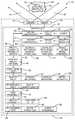
- FIG. 1is a diagram of an object tracking system in accordance with one embodiment
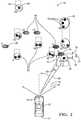
- FIG. 2is a traffic scenario experienced by the system of FIG. 1 in accordance with one embodiment
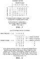
- FIG. 3is a feasibility matrix determined by the system of FIG. 1 in accordance with one embodiment
- FIG. 4is a list of feasible match patterns determined by the system of FIG. 1 in accordance with one embodiment.
- FIG. 5is an accumulation of match probabilities determined by the system of FIG. 1 in accordance with one embodiment.
- FIG. 1illustrates a non-limiting example of an object tracking system 10 , hereafter the system 10 , which is generally suitable for use on an automated vehicle, hereafter the host-vehicle 12 .
- the system 10includes a camera 14 used to capture an image of a vision-field-of-view 16 , hereafter the VFOV 16 of the camera 14 , and a radar-sensor 18 used to detect a radar-signal reflected from a radar-field-of-view 20 , hereafter the RFOV 20 .
- the VFOV 16 and the RFOV 20overlap such that a majority fraction of each covers the same area, so that an instance of an object detected in the peripheral sensing area one device (the camera 14 or the radar-sensor 18 ) is not missed by the other device.
- FIG. 1may suggest that the camera 14 and the radar-sensor 18 are arranged side-by-side, this is only to simplify the illustration. It is recognized that aligning the camera 14 and the radar-sensor 18 with each other is simplified if the two devices are located close together, but this is not are requirement of the system 10 . It is believed that the construction and operation of the system 10 would be generally optimized if the VFOV 16 and the RFOV 20 were the essentially the same areas as suggested in FIG. 2 .
- the system 10also includes a controller 22 in communication with the camera 14 and the radar-sensor 18 .
- the controller 22may include a processor (not specifically shown) such as a microprocessor or other control circuitry such as analog and/or digital control circuitry including an application specific integrated circuit (ASIC) for processing data as should be evident to those in the art.
- the controller 2may include memory (not specifically shown), including non-volatile memory, such as electrically erasable programmable read-only memory (EEPROM) for storing one or more routines, thresholds, and captured data.
- EEPROMelectrically erasable programmable read-only memory
- the one or more routinesmay be executed by the processor to perform steps for determining, for example, the identity, location, speed, and direction of travel of one or more instance of actual-objects 24 based on signals received by the controller 22 from the camera 14 and the radar-sensor 18 and processed as described in more detail below.
- the actual-objects 24 in FIG. 2are indicated by the dashed rectangles, where the relative sizes of the rectangles indicate a relative size of the actual-objects 24 with respect to each other.
- the system 10 described hereinin which data from radar-sensor 18 and the camera 14 is fused, is implemented on the host-vehicle 12 ; however this is not a requirement.
- the actual-objects 24 in the scenei.e. the other-vehicles, can be moving in any direction, but for simplicity of explanation here, it is assumed that all objects are moving in roughly the same direction as the host-vehicle 12 .
- a vision-portion 50 of the system 10 onboard the host-vehicle 12is assumed to work independently of a radar-portion 52 of the system 10 .
- FIG. 2shows a plan-view (“bird's eye” view) of this.
- the radar-portion 52 of the system 10 onboard the host-vehicle 12reports at each time instant a list of ‘detections’.
- Each detection instancetypically consists of a range value, a range-rate value, and an azimuth angle value.
- the radar trackerobserves these detection lists over time, and creates a list of ‘tracklets’ (i.e., radar tracks on scattering centers, which are radar ‘bright spots’ on the target vehicle).
- Each trackletcontains information gleaned over time, such as position, velocity, acceleration and status information indicating how recently a detection instance was used to update this tracklet.
- the radar-portion 52provides a list of radar tracks, which are assumed to mostly be tracking scattering centers on the vehicles it detects. There are generally more than one such tracklet on a given vehicle which is unobstructed and at reasonably close range. Functionality in the fusion tracker referred to as “Grouping”, is assumed to have already grouped these tracklets into “radar globs”. This task isn't very difficult in an ordinary highway scene with moderate spacing between vehicles. Thus, each radar glob is effectively a grouped radar track on a vehicular object. The specific way in which this grouped radar track is formed (e.g., by grouping tracklets) is not important to the matching algorithm. For example, a different but perfectly allowable scheme would be one in which the grouped radar track is formed by directly tracking the sequence of sets of multiple detections on the object (i.e., “tracking groups”, rather than “grouping tracks”).
- the matching or fusion algorithm described hereinis generally directed to detecting vehicular objects, i.e. other vehicles. This makes some of the matching easier. For example, it would appear to be a reasonable assumption that the radar-sensor can detect any vehicle which the camera can detect. This restriction to a subset of the possible objects in the scene reduces the combinatorial complexity of the matching making the calculations feasible in real-time on an automotive-grade processor. Ideally, when considering how to match radar and vision tracks, one would have estimates of the sensor systems' uncertainties in the estimates they are providing (in addition to the estimates themselves). Since these estimates are unavailable for the sensor systems used in some embodiments of the system 10 , information borrowed from ‘expert knowledge’ of these systems is utilized.
- the vision-portion 50 of the system 10is relatively good at estimating the centroid azimuth angle, and is also good at classifying the type of object (e.g., Car, Motorcycle, Truck, etc.).
- the vision-portion 50is, relatively speaking, not especially good at estimating position or velocity of an object. These estimates are utilized by the matching algorithm, but only with a healthy fear for their accuracy. For example, a 100% error in the estimated longitudinal position of an object is not uncommon for the vision system, meaning an object determined to be at 100 m downrange might actually be at 200 m.
- the radar-portion 52is relatively good at measuring range and range-rate, but not so good at measuring the azimuth angle. The complementarity of these strengths/weaknesses in the radar-portion 52 and vision-portion 50 of the system 10 is what makes the fusion of their estimates so desirable, but also makes the matching difficult.
- the term ‘feasible match pair’refers to a particular vision-track 26 ( FIG. 1 ) and radar-glob 28 pair which are deemed by the matching algorithm to be a legitimate candidate pair for matching, based on consideration of the possible errors in their estimates.
- a ‘feasible match pattern’is a match pattern consisting of N feasible match pairs.
- a feasible match patternmay later be deemed ‘infeasible’ by an occlusion-test 30 due to an apparent occlusion of one of the proposed matches by a closer object which apparently should be blocking the camera's view of the more distant object (making that proposed match of the vision track to that more distant radar glob appear to be impossible).
- Any single problem with a match patterncauses the whole pattern to be infeasible. It is expected that some of the available radar globs may not be matched to vision tracks because they correspond to objects which are detected by the radar but not by vision.
- the matching algorithm described hereineffectively calculates for each instance of the vision-track 26 (e.g. V 1 , V 2 . . . V 5 ), the probability that a particular instance of the vision-track 26 should be matched to each of a (limited) number of instances of the radar-glob 28 (e.g. R 1 , R 2 . . . R 8 ).
- an outcome of the algorithmis a match-probability 32 that a particular instance of the vision-track 26 , e.g. V 3 , is matched to a particular instance of the radar-glob 28 (e.g. R 3 , R 4 , R 1 ).
- a match-probability 32that a particular instance of the vision-track 26 , e.g. V 3 , is matched to a particular instance of the radar-glob 28 (e.g. R 3 , R 4 , R 1 ).
- the match-probability 32 for other combinations of a particular instance of the vision-track 26 to a particular instance of the radar-glob 28are set to zero by the occlusion-test 30 or other tests that will be described in more detail later, and/or because the probability is too low, e.g. below some threshold. That is, for each instance of the vision-track 26 there are several candidates of the radar-glob 28 considered suitable for matching. It is also contemplated that the match-probability 32 may be determined based on present information from the camera 14 and the radar-sensor 18 , and on historical information as will be described in more detail below.
- V 3were matched to R 1 prior to the present instant (which has match probability 0.08), and a predetermined minimum threshold of 0.10 had been established, then that radar/vision match would be split apart.
- all of the required new-match and break-up-match actionsare considered simultaneously in a re-organize test 34 . This allows a minimum of undesirable fused track ID switching to result from the re-organize test 34 .
- motion statusrefers to a determination of overall over-the-ground motion, i.e., oncoming, stationary, receding.
- Clean up radar/vision match probabilitiesby removing any New/Dead radar-globs from probability lists. Special handling of case of zero feasible patterns. Reduce all match-probabilities (first step of low-pass filtering of match probabilities). Accumulate match info from feasible-match-patterns to get instantaneous raw-probabilities. Update match-probabilities using raw-probability values (second step of low-pass filtering). Plan re-organize test (based on match probabilities). Re-organize radar/vision matches.
- FIG. 3illustrates a non-limiting example of a feasibility-matrix 38 .
- the match-feasibility 36is determined for each possible pairing.
- the resultsare stored in the feasibility-matrix 38 .
- This ‘pre-gating’ of potential radar/vision match-upsis done to reduce combinatorial complexity and is based on similarities between radar and vision tracks in the areas of motion status, azimuth angle, longitudinal position and longitudinal velocity.
- the gates for this pre-gatingmay be varied, for example may be widened when a particular radar/vision pair has been matched for a long time and is believed to be a correct match-up.
- the widened gatecan be of use in maintaining this correct match even if there are brief errors in the vision or radar tracks which are sufficiently large to otherwise cause a match break-up.
- a sequence of all possible feasible match patternsis then generated. Some of these feasible match patterns may be rejected later by the occlusion-test 30 .
- this ‘pre-gating’ using the feasible match pair determination and the resulting instance of the feasibility-matrix 38is to significantly reduce the number of match patterns that need to be examined.
- match patternsFor the non-limiting example in the figures with five instances of the vision-tracks 26 and eight instances of the radar-globs 28 , there are 6720 match patterns which would need to be considered without the pre-gating.
- FIG. 4illustrates a non limiting example of a list of feasible-match-patterns 40 from FIG. 3 that are looped over with the intent of creating a final list of patterns which also passed the occlusion-test 30 .
- a quality-value 42is also measured for each of instance of the feasible-match-patterns 40 .
- the purpose of the occlusion-test 30is to rule out unlikely matches. For example, say there are two cars in front of the host-vehicle 12 , all in the same lane, and there is a distinct instance of the radar-glob 28 for each of the two preceding vehicles. There is also an instance of the vision-track 26 characterized by an azimuth angle that is a good match to either of the radar globs 28 . The occlusion-test determines that it is unlikely that the vision-portion 50 is seeing the second (more distant) car, because the first (closest) car would be blocking the view of or line of sight to the second car. Because of this, a match between the vision-track 26 and the first car would be approved by the occlusion-test 30 .
- the occlusion-test 30would invalidate that match pattern, and processing would continue on to the next match-pattern on the list. That is, given that a match-pattern under consideration may try to match the further instance of the radar-glob 28 to the instance of the vision-track 26 under consideration, and the nearer instance of the radar-glob 28 is also a legitimate match to the instance of the vision-track 26 under consideration (e.g.
- the occlusion-test 30will mark the match-pattern that pairs the vision-track 26 to the further (occluded) instance of the radar-glob 28 as ‘infeasible’ because of visual occlusion by the nearer radar-glob.
- the current match pattern under considerationalso commands that the closer radar glob be matched to a different vision track. In that case, the more distant match will be allowed. An example of this can happen when one vehicle is passing another vehicle and then changes lanes to be in front of that other vehicle.
- the vision systemcan hold on to the vision track on the more distant vehicle for an interval of time, even though that distant vehicle is largely occluded by the closer vehicle.
- Each feasible match patternhas a quality-value 42 determined.
- the quality-value 42is intended to represent a Bayesian-style likelihood under presumed error models.
- the quality-value 42may be calculated as a reciprocal of a sum over the indicated match pairs of the weighted squared differences in azimuth angle, longitudinal position, and longitudinal velocity in each radar-glob/vision-track pair.
- the quality-value 42is decreased if any of the indicated matches involve a ‘suspicious’ radar-glob (i.e., the fusion tracker has low confidence in the validity or accuracy of one or more of the tracklets in that radar-glob).
- a matched radar/vision pairwill have an increased value of the quality-value 42 if the radar-glob 28 and vision-track 26 estimates agree well in those three categories. The more they disagree with each other, the less the quality-value 42 , hence, the less the likelihood or probability that they actually match.
- the quality-value 42 for each of the final feasible match patternsare normalized to provide a normalized-value 44 scaled so the sum of the normalized-values is equal to 1.0.
- these normalized-valuesare interpreted as probabilities of match patterns being correct.
- FIG. 5illustrates a non-limiting example of a key step in calculating the raw-probability 46 for each vision/radar pair, e.g. for vision-track Vi and radar-glob Rj.
- the way this matching algorithm worksis to identify a list of acceptable potential match patterns, give each of them a normalized-value 44 , then add up all of the normalized-values 44 for match patterns which match up vision-track Vi and radar-glob Rj.
- V 1is matched to radar-glob ID 2 (R 2 ) in every single match pattern on the list.
- R 2radar-glob ID 2
- the raw-probability 46 for this pairwill sum to 1.0. This probability value matches one's intuition based on the observation that this pair was matched in every feasible pattern. In cases where this pair is matched in only a fraction of the patterns, the raw-probability 46 will be between 0.0 and 1.0, depending on the quality/probability of the patterns in which that match appeared. If the pair is matched in none of the patterns, the raw-probability 46 will be 0.0.
- ⁇ x k-1represents the reduction in match probabilities
- (1 ⁇ )u krepresents the match probability update using the raw value.
- the u k termis effectively equal to zero, and only the probability reduction step takes place.
- a possible value for ais 0.8.
- a particular radar/vision match pairhas a match probability of 0.0 when suddenly that pair looks like a great match, and a raw-probability value of 1.0 is computed. If this raw-probability is maintained for several steps, the (filtered) match probability will take the values 0.0, 0.2, 0.36, 0.49, 0.59, 0.67, . . . At some point, this value will exceed a threshold (e.g., 0.6) and the radar/vision matches will be re-organized to execute that match-up. So for this threshold, it takes (at least) 5 steps for the match to be made.
- a thresholde.g., 0.6
- an exceptionmay be allowed under some conditions. If the vision track is currently unmatched and then has a sufficiently high value of the raw-probability 46 to a particular radar glob, then the filtered match probability is allowed to jump to 1.0. This allows for an immediate match to be available for fusion in these unambiguous match cases. If the match is ambiguous for that vision track, then the probabilities must be allowed to drift up or down in accordance with the scheme described above.
- the match probabilitiesare inspected for each vision track.
- the radar glob which this vision track wantsis already matched to a different vision track, so that other fused track will need to be split apart before any new matching can take place.
- the vision track under considerationmay already be matched to a radar glob, so that fused track will need to be split apart.
- the re-organize test 34is conceptually straightforward. It first breaks apart all of the fused tracks which contain radar or vision pieces needed in the re-organize test, and then re-assembles the pieces as indicated by the match probabilities.
- This stepis a conceptually simple implementation of the planned re-organize test of the radar and vision pieces of fused tracks.
- the planning stephas already mapped out which radar/vision fused tracks will need to be broken apart, and which of the pieces will need to be put together.
- the fused track IDs of all of the fused tracks involved in the re-organize testhas been predetermined in the planning in a way which minimizes unnecessary ID switching.
- the fused track states of the re-organized fused tracksare adjusted to account for the state values of the new radar and vision pieces.
- the algorithm described hereinmay also include tests to identify suspiciousness of radar globs, vision/radar pairs with long histories of good matching, suspected disappearing radar tracklets, etc.
- Match probabilitiesare maintained for each vision track to a small set of potential radar-globs which are feasible matches to that vision-track. These match probabilities are obtained by low-pass filtering the values of the raw-probability 46 for each potential vision/radar match-up.
- the raw-probability 46 for a particular vision/radar pairis obtained by summing the normalized-values 44 of the feasible match patterns which indicate that match-up.
- the list of feasible match patternsis obtained efficiently by pre-gating recorded by a feasibility matrix which indicates which individual vision/radar pairs are sufficiently similar that their match-up could be part of a feasible match pattern.
- Each resulting feasible match patternis additionally scrutinized by the Occlusion function for sensibility, and the match pattern's quality is measured as a function of the discrepancies between radar and vision track state information in each of the indicated radar/vision matches in the pattern.
- vision/radar match probabilitiesare compared to thresholds and, if needed, re-organization of some of the existing fused tracks is planned and implemented in order to come into compliance with the dictates of the match probabilities.
- the object tracking system 10which is generally suitable for use on an automated vehicle (e.g. the host-vehicle 12 ), includes a camera 14 used to capture an image of the VFOV 16 of the camera 14 , and a radar-sensor 18 used to detect a radar-signal reflected from the RFOV 20 of the radar-sensor 18 which overlaps the VFOV 16 .
- the overlapis such that the VFOV 16 and the RFOV 20 are the same areas or essentially (e.g. >90%) the same areas, but this is not a requirement.
- the system 10includes a controller 22 in communication with the camera 14 and the radar-sensor 18 so that the controller 22 receives data or information from the camera 14 and the radar-sensor 18 for detecting the presence of actual-objects 24 in the respective fields-of-view.
- the controller 22is configured or programmed to perform a number of steps to match instances of an object 54 detected by the camera 14 with instances of grouped-tracklets 56 detected by the radar-sensor 18 . While the steps below are characterized in terms of first, second, third, etc., steps, this does not suggest that the steps must be performed in the exact order presented, or that other intervening steps are excluded, or that all of the steps described are absolutely required.
- a first stepmay be to assign a vision-identification 58 to each instance of a vision-track 26 associated with an instance of an object 54 detected by the controller in the image (i.e. information or signal) from the camera 14 .
- FIG. 2illustrates a non-limiting example of a traffic scenario that the system 10 may encounter where the vision-identification 58 is assigned based on the detection of the actual-objects 24 and are indicated as V 1 , V 2 , V 3 , V 4 , and V 5 .
- a second stepmay be to assign a radar-identification 60 to each instance of a radar-glob 28 associated with an instance of grouped-tracklets 56 indicated by the radar-signal detected by the radar-sensor 18 .
- FIG. 2illustrates a non-limiting example where the radar-identification 60 is assigned based on the detection of the actual-objects 24 and are indicated as R 1 , R 2 , R 3 , R 4 , R 5 , R 6 , R 7 , and R 8 .
- a third stepmay be to determine a match-feasibility 36 for each combination of vision-track 26 and radar-glob 28 .
- Each match-feasibility 36is a binary-value set equal to zero (0) or one (1) depending on the outcome of a comparison or test of how closely related an instance of a vision-track 26 and a radar-glob 28 are to each other.
- the match-feasibility 36 of a particular combination of vision-track 26 and radar-glob 28is set to one (1) when at least one of a) an azimuth-difference 62 between a vision-angle 64 ( FIG.
- a distance-difference 70 between a vision-distance of the vision-track 26 and a radar-distance of a radar-glob 28is less than a distance-threshold 72 , e.g. five meters (5 m) or twenty percent (20%) whichever is greater; and c) a speed-difference 74 between a vision-speed 76 of the vision-track 26 and a radar-speed 78 of a radar-glob 28 is less than a speed-threshold 80 , e.g.
- , distance-difference
- , and speed-difference
- the vision-speed 76 and the radar-speed 78may be indicative of a longitudinal-velocity of the vision-track 26 and the radar-glob 28 , respectively. That is, only the portion of the vision-speed 76 and the radar-speed 78 that is parallel to the present travel-direction of the host-vehicle 12 may be considered, and any relative lateral movement may be ignored.
- the vision-distance (not shown) and the radar-distance (not shown)may be indicative of a longitudinal-position of the vision-track and the radar-glob, respectively. That is, only the distance parallel to the present travel-direction of the host-vehicle 12 may be considered, and any lateral offset may be ignored.
- the match-feasibility 36 for a particular combination of vision-track 26 and radar-glob 28may be set equal to zero (0) when the azimuth-difference 62 is not less than the azimuth-threshold 68 regardless of the values of the distance-difference 70 and the speed-difference 74 .
- each match-feasibilityis set equal to one (1) only when all of the tests are passed, e.g.
- the azimuth-difference 62is less than the azimuth-threshold 68
- the distance-difference 70is less than the distance-threshold 72
- the speed-difference 74 betweenis less than the speed-threshold 80 .
- each match-feasibilityis set equal to one (1) when at least one of a) the azimuth-difference is less than the azimuth-threshold, b) the distance-difference is less than the distance-threshold, c) the speed-difference between is less than the speed-threshold, and d) a vision-motion-status (not shown) of the vision-track 26 matches a radar-motion-status (not shown) of the radar glob 28 , where the vision-motion-status and the radar-motion-status are each characterized by one of oncoming, stationary, and receding which indicate the direction of over-the-ground motion relative to the host-vehicle 12 .
- over-the-ground motionnot motion relative to the host-vehicle's motion
- over-the-ground motionis key. For example, assume there is another car in front of the host-vehicle 12 which is moving in the same direction but at a reduced speed. The relative motion of that other vehicle is towards the host-vehicle, but it is not characterized as oncoming. Since its over-the-ground motion is in the same direction as the host-vehicle is moving, it is characterized as receding.
- a fourth stepmay be to select from all possible vision-track and radar-glob pairing-combinations a list of feasible-match-patterns 40 .
- a pairing-combinationis characterized as a feasible-match-pattern when the match-feasibility 36 of each combination of vision-track 26 and radar-glob 28 in the pairing-combination is equal to one (1).
- all of the match-feasibilities 36 of a pairing-combinationmay be multiplied together. If the result is one, then each instance of the match-feasibility is one. However, if the result is zero, then at least one instance of the match-feasibility is zero.
- a fifth stepmay be to determine a quality-value 42 of each instance of the feasible-match-patterns 40 .
- the quality-value 42may be based on a reciprocal of a weighted-combination of instances of the azimuth-difference 62 , the distance-difference 70 , and the speed-difference 74 used to determine the match-feasibility 36 .
- the weighting of each of the differencesmay be predetermined values, e.g. an azimuth-weighting 82 , a distance-weighting 84 , and a speed-weighting 86 , which may be predetermined values determined by empirical testing.
- a seventh stepmay be to calculate a raw-probability 46 for each combination of vision-track 26 and radar-glob 28 by summing the normalized-values 44 of the feasible-match-patterns 40 that indicate a match for that combination of vision-track 26 and radar-glob 28 .
- An eighth stepmay be to determine a match-probability 32 for each combination of vision-track 26 and radar-glob 28 by low-pass filtering 48 of the raw-probability 46 obtained for that combination.
- a ninth stepmay be to determine a need for re-organize test 34 of the existing associations between vision-tracks 26 and radar-globs 28 by comparing the match-probabilities 32 for combinations of vision-track 26 and radar-glob 28 to an upper-threshold 88 and a lower-threshold 90 , and implement a re-organize test 34 of associations between vision-tracks 26 and radar-globs 28 when one of the match-probabilities 32 transitions from less than to greater than the upper-threshold 88 or from greater than to less than the lower-threshold 90 .
- An additional step between the fourth step and the fifth stepmay be to perform an occlusion-test 30 on radar-globs characterized by substantially equal values of azimuth-angle to null the match-probability for any combination of vision-track 26 and radar-glob 28 that the occlusion-test 30 indicates is not possible because the line of site to one is occluded by the other.
- an object tracking system(the system 10 ), a controller 22 for the system 10 and a method described in terms of steps is provided.
- an improved way to match the vision-tracks 26 detected by the camera 14 to radar-globs 28 detected by the radar-sensor 18is provided.
- the amount of data processinghas been reduced by excluding some of the possible combinations via a gating process that determine the match-feasibility 36 of each possible combination.
Landscapes
- Engineering & Computer Science (AREA)
- Remote Sensing (AREA)
- Radar, Positioning & Navigation (AREA)
- Physics & Mathematics (AREA)
- General Physics & Mathematics (AREA)
- Computer Networks & Wireless Communication (AREA)
- Theoretical Computer Science (AREA)
- Electromagnetism (AREA)
- Multimedia (AREA)
- Data Mining & Analysis (AREA)
- Bioinformatics & Computational Biology (AREA)
- General Engineering & Computer Science (AREA)
- Evolutionary Computation (AREA)
- Evolutionary Biology (AREA)
- Computer Vision & Pattern Recognition (AREA)
- Bioinformatics & Cheminformatics (AREA)
- Artificial Intelligence (AREA)
- Signal Processing (AREA)
- Life Sciences & Earth Sciences (AREA)
- Radar Systems Or Details Thereof (AREA)
- Mechanical Engineering (AREA)
- Closed-Circuit Television Systems (AREA)
- Image Analysis (AREA)
Abstract
Description
| Create a list of radar-globs to be considered. |
| Calculate pertinent features of these radar-globs, e.g., motion status, |
| position, velocity. |
| Create a list of vision-tracks. |
| Calculate pertinent features, e.g., motion status. |
| Feasibility Testing of candidate match pairs to create a Feasibility-Matrix. |
| Remove from consideration any totally infeasible radar globs or vision |
| tracks. |
| LOOP over feasible-match-patterns (match patterns created by inspection |
| of Feasibility Matrix). |
| Occlusion test. |
| IF pattern okay, |
| Add to list of match patterns, |
| Calculate quality-value of match pattern. |
| END |
| END LOOP |
| Normalize match pattern quality-values (e.g., so sum equals 1.0). |
| Clean up radar/vision match probabilities by removing any New/Dead |
| radar-globs from probability lists. |
| Special handling of case of zero feasible patterns. |
| Reduce all match-probabilities (first step of low-pass filtering of match |
| probabilities). |
| Accumulate match info from feasible-match-patterns to get instantaneous |
| raw-probabilities. |
| Update match-probabilities using raw-probability values (second step |
| of low-pass filtering). |
| Plan re-organize test (based on match probabilities). |
| Re-organize radar/vision matches. |
Claims (9)
Priority Applications (3)
| Application Number | Priority Date | Filing Date | Title |
|---|---|---|---|
| US15/000,730US10565468B2 (en) | 2016-01-19 | 2016-01-19 | Object tracking system with radar/vision fusion for automated vehicles |
| EP17150307.1AEP3196668B1 (en) | 2016-01-19 | 2017-01-04 | Object tracking system with radar/vision fusion for automated vehicles |
| CN201710286682.0ACN107238834B (en) | 2016-01-19 | 2017-01-19 | Object Tracking System Using Radar/Vision Fusion for Autonomous Vehicles |
Applications Claiming Priority (1)
| Application Number | Priority Date | Filing Date | Title |
|---|---|---|---|
| US15/000,730US10565468B2 (en) | 2016-01-19 | 2016-01-19 | Object tracking system with radar/vision fusion for automated vehicles |
Publications (2)
| Publication Number | Publication Date |
|---|---|
| US20170206436A1 US20170206436A1 (en) | 2017-07-20 |
| US10565468B2true US10565468B2 (en) | 2020-02-18 |
Family
ID=57714549
Family Applications (1)
| Application Number | Title | Priority Date | Filing Date |
|---|---|---|---|
| US15/000,730Active2038-03-18US10565468B2 (en) | 2016-01-19 | 2016-01-19 | Object tracking system with radar/vision fusion for automated vehicles |
Country Status (3)
| Country | Link |
|---|---|
| US (1) | US10565468B2 (en) |
| EP (1) | EP3196668B1 (en) |
| CN (1) | CN107238834B (en) |
Cited By (11)
| Publication number | Priority date | Publication date | Assignee | Title |
|---|---|---|---|---|
| US11086007B2 (en)* | 2016-07-29 | 2021-08-10 | Denso Corporation | Target detection device |
| US20220130109A1 (en)* | 2020-10-26 | 2022-04-28 | Mohammad Amin Arbabian | Centralized tracking system with distributed fixed sensors |
| EP4002300A1 (en) | 2020-11-18 | 2022-05-25 | Aptiv Technologies Limited | Kurtosis based pruning for sensor-fusion systems |
| EP4043921A1 (en) | 2021-02-15 | 2022-08-17 | Aptiv Technologies Limited | Multiple hypothesis-based fusion of sensor data |
| US20220299627A1 (en)* | 2019-12-04 | 2022-09-22 | Huawei Technologies Co., Ltd. | Apparatus and Method for Collecting and Auto-Labelling Measurement Data in Traffic Scenario |
| US11474234B2 (en)* | 2018-03-20 | 2022-10-18 | Hl Klemove Corp. | Device and method for estimating distance based on object detection |
| US20230046396A1 (en)* | 2021-08-13 | 2023-02-16 | Aptiv Technologies Limited | Occlusion Constraints for Resolving Tracks from Multiple Types of Sensors |
| US11694446B2 (en) | 2020-06-09 | 2023-07-04 | Samsung Electronics Co., Ltd. | Advanced driver assist system and method of detecting object in the same |
| US11774582B2 (en) | 2020-01-28 | 2023-10-03 | Aptiv Technologies Limited | Imaging and radar fusion for multiple-object tracking |
| US20230410490A1 (en)* | 2022-05-11 | 2023-12-21 | Aptiv Technologies Limited | Deep Association for Sensor Fusion |
| US12080072B2 (en) | 2021-03-18 | 2024-09-03 | Aptiv Technologies AG | History-based identification of incompatible tracks |
Families Citing this family (64)
| Publication number | Priority date | Publication date | Assignee | Title |
|---|---|---|---|---|
| US10317522B2 (en)* | 2016-03-01 | 2019-06-11 | GM Global Technology Operations LLC | Detecting long objects by sensor fusion |
| EP3415945B1 (en) | 2017-06-12 | 2024-01-10 | Aptiv Technologies Limited | Method of determining the yaw rate of a target vehicle |
| US11555913B2 (en)* | 2017-11-13 | 2023-01-17 | Mitsubishi Electric Corporation | Object recognition device and object recognition method |
| US10466346B2 (en)* | 2017-11-17 | 2019-11-05 | Gm Global Technology Operations, Llc | Method and apparatus for continuous tracking in a multi-radar system |
| CN109960254B (en)* | 2017-12-25 | 2022-09-23 | 深圳市优必选科技有限公司 | Robot and path planning method thereof |
| IL258347B (en) | 2017-12-31 | 2020-11-30 | Elta Systems Ltd | System and method for integration of data received from gmti radars and electro optical sensors |
| EP3525000B1 (en)* | 2018-02-09 | 2021-07-21 | Bayerische Motoren Werke Aktiengesellschaft | Methods and apparatuses for object detection in a scene based on lidar data and radar data of the scene |
| EP3546978B1 (en)* | 2018-03-29 | 2021-12-08 | Aptiv Technologies Limited | Method for testing a target object as single point scattering center |
| EP3754372A4 (en)* | 2018-03-30 | 2021-02-24 | Mitsubishi Electric Corporation | OBJECT IDENTIFICATION DEVICE |
| EP3572839A1 (en) | 2018-05-23 | 2019-11-27 | Aptiv Technologies Limited | Method of estimating a velocity magnitude of a moving target in a horizontal plane and radar detection system |
| DE102018208205A1 (en) | 2018-05-24 | 2019-11-28 | Ford Global Technologies, Llc | Method for mapping the environment of motor vehicles |
| EP3575827B1 (en) | 2018-06-01 | 2024-07-31 | Aptiv Technologies AG | Method for robust estimation of the velocity of a target using a host vehicle |
| CN110609274B (en)* | 2018-06-15 | 2022-07-01 | 杭州海康威视数字技术股份有限公司 | Distance measurement method, device and system |
| CN108921925B (en)* | 2018-06-27 | 2022-12-09 | 广州视源电子科技股份有限公司 | Semantic point cloud generation method and device based on lidar and vision fusion |
| US11035943B2 (en)* | 2018-07-19 | 2021-06-15 | Aptiv Technologies Limited | Radar based tracking of slow moving objects |
| EP3611541B1 (en) | 2018-08-16 | 2024-07-03 | Aptiv Technologies AG | Method of determining an uncertainty estimate of an estimated velocity |
| CN109270523B (en)* | 2018-09-21 | 2020-09-18 | 宝沃汽车(中国)有限公司 | Multi-sensor data fusion method and device and vehicle |
| CN110378178B (en)* | 2018-09-30 | 2022-01-28 | 毫末智行科技有限公司 | Target tracking method and device |
| EP3861370A1 (en)* | 2018-10-01 | 2021-08-11 | KPIT Technologies Limited | Perception sensors based fusion system for vehicle control and method thereof |
| US10878282B2 (en)* | 2018-10-15 | 2020-12-29 | Tusimple, Inc. | Segmentation processing of image data for LiDAR-based vehicle tracking system and method |
| CN109459750B (en)* | 2018-10-19 | 2023-05-23 | 吉林大学 | A multi-vehicle tracking method based on the fusion of millimeter-wave radar and deep learning vision |
| CN109375211B (en)* | 2018-12-10 | 2023-03-10 | 西安电子科技大学 | Radar and multi-optical equipment-based mobile unmanned platform target searching method |
| JP7169873B2 (en)* | 2018-12-27 | 2022-11-11 | 株式会社デンソー | Driving support device |
| CN111382768B (en) | 2018-12-29 | 2023-11-14 | 华为技术有限公司 | Multi-sensor data fusion method and device |
| CN111856445B (en)* | 2019-04-11 | 2023-07-04 | 杭州海康威视数字技术股份有限公司 | Target detection method, device, equipment and system |
| CN110095770A (en)* | 2019-04-26 | 2019-08-06 | 东风柳州汽车有限公司 | The detection method of vehicle-surroundings object |
| IT201900006735A1 (en)* | 2019-05-10 | 2020-11-10 | Sacertis S R L | Method of investigation of a structure and procedure to define an optimal method of investigation of the structure itself |
| KR20200133863A (en) | 2019-05-20 | 2020-12-01 | 삼성전자주식회사 | Advanced driver assist device, method of calibrationg the same and method of detecting object in the saem |
| CN110133637B (en)* | 2019-06-05 | 2021-06-01 | 中国科学院长春光学精密机械与物理研究所 | Target positioning method, device and system |
| CN110517483B (en)* | 2019-08-06 | 2021-05-18 | 新奇点智能科技集团有限公司 | Road condition information processing method and digital rail side unit |
| US11994579B2 (en)* | 2019-08-22 | 2024-05-28 | Bdcm A2 Llc | Hybrid radar and camera edge sensors |
| CN110794405B (en)* | 2019-10-18 | 2022-06-10 | 北京全路通信信号研究设计院集团有限公司 | Target detection method and system based on camera and radar fusion |
| CN112904331B (en)* | 2019-11-19 | 2024-05-07 | 杭州海康威视数字技术股份有限公司 | Method, device, equipment and storage medium for determining movement trajectory |
| US11594144B2 (en)* | 2020-01-31 | 2023-02-28 | Honeywell International Inc. | Collision awareness using cameras mounted on a vehicle |
| CN111402296B (en)* | 2020-03-12 | 2023-09-01 | 浙江大华技术股份有限公司 | Target tracking method and related device based on camera and radar |
| CN111505624B (en)* | 2020-04-30 | 2022-07-01 | 中国汽车工程研究院股份有限公司 | Environment sensing method based on machine vision and millimeter wave radar data fusion |
| US12320887B2 (en)* | 2020-07-22 | 2025-06-03 | Plato Systems, Inc. | Spatial sensor system with background scene subtraction |
| CN112285700B (en)* | 2020-08-24 | 2023-12-15 | 江苏大学 | Maneuvering target tracking method based on fusion of laser radar and millimeter wave radar |
| EP3961255A1 (en)* | 2020-08-28 | 2022-03-02 | Aptiv Technologies Limited | Driver assistance system for a vehicle, vehicle and a driver assistance method implementable by the system |
| CN112130136B (en)* | 2020-09-11 | 2024-04-12 | 中国重汽集团济南动力有限公司 | Comprehensive perception system and method for traffic targets |
| CN116324506B (en)* | 2020-09-24 | 2025-05-16 | 三菱电机株式会社 | Information processing system, information processing apparatus, computer readable recording medium, and information processing method |
| US11719805B2 (en)* | 2020-11-18 | 2023-08-08 | Infineon Technologies Ag | Radar based tracker using empirical mode decomposition (EMD) and invariant feature transform (IFT) |
| CN112562009A (en)* | 2020-12-03 | 2021-03-26 | 深圳宇磐科技有限公司 | Method and system for automatically calibrating camera equipment parameters and installation attitude parameters |
| DE102021105659A1 (en) | 2020-12-09 | 2022-06-09 | Symeo Gmbh | Method, device and radar system for tracking objects |
| EP4260092A1 (en)* | 2020-12-09 | 2023-10-18 | Symeo GmbH | Method, apparatus and radar system for tracking objects |
| CN112731371B (en)* | 2020-12-18 | 2024-01-23 | 重庆邮电大学 | Laser radar and vision fusion integrated target tracking system and method |
| CN112560735B (en)* | 2020-12-22 | 2025-04-08 | 上海有个机器人有限公司 | Laser and visual image fusion door detection method and storage medium |
| US12399272B2 (en)* | 2021-07-16 | 2025-08-26 | Aptiv Technologies AG | Motion classification using low-level detections |
| CN113505732A (en)* | 2021-07-26 | 2021-10-15 | 浙江大华技术股份有限公司 | Visual target determination method and device, storage medium and electronic device |
| CN113740843B (en)* | 2021-09-07 | 2024-05-07 | 中国兵器装备集团自动化研究所有限公司 | Motion state estimation method and system for tracking target and electronic device |
| CN115993597A (en)* | 2021-10-18 | 2023-04-21 | 长沙中车智驭新能源科技有限公司 | Visual radar perception fusion method and terminal equipment |
| US12093048B2 (en)* | 2021-11-11 | 2024-09-17 | Aptiv Technologies AG | Clustering track pairs for multi-sensor track association |
| CN114442083B (en)* | 2021-12-24 | 2025-03-28 | 福建新继船舶服务有限公司 | An adaptive weighted data fusion method based on vision and multi-source radar |
| US12123945B2 (en)* | 2022-02-16 | 2024-10-22 | Aptiv Technologies AG | Multi-scan sensor fusion for object tracking |
| CN114998886B (en)* | 2022-08-04 | 2022-10-28 | 智慧互通科技股份有限公司 | Vehicle tracking method and device based on radar vision fusion |
| US12248058B2 (en)* | 2022-09-02 | 2025-03-11 | Aptiv Technologies AG | Track association based on azimuth extension and compactness errors |
| CN115695679B (en)* | 2022-10-24 | 2024-11-22 | 北京有竹居网络技术有限公司 | Triple depth module matching method and device, mobile terminal, medium and chip |
| CN115657012B (en)* | 2022-12-23 | 2023-04-18 | 深圳佑驾创新科技有限公司 | Matching method, device and equipment of image target and radar target and storage medium |
| EP4414746A1 (en) | 2023-02-08 | 2024-08-14 | Continental Autonomous Mobility Germany GmbH | Multi-object detection and tracking |
| CN116630765B (en)* | 2023-07-24 | 2023-09-26 | 济南卓伦智能交通技术有限公司 | Bicycle fusion sensing system based on multiple information |
| CN117093872B (en)* | 2023-10-19 | 2024-01-02 | 四川数字交通科技股份有限公司 | Self-training method and system for radar target classification model |
| US20250199121A1 (en)* | 2023-12-15 | 2025-06-19 | Waymo Llc | Detection and classification of traffic signs using camera-radar fusion |
| CN118018851A (en)* | 2024-02-27 | 2024-05-10 | 上海高德威智能交通系统有限公司 | Target capture method, device and electronic equipment based on thunderball system |
| CN118628881B (en)* | 2024-08-09 | 2024-11-29 | 纽劢科技(上海)有限公司 | Fusion method of vision camera and millimeter wave radar tracking target |
Citations (9)
| Publication number | Priority date | Publication date | Assignee | Title |
|---|---|---|---|---|
| US20030011509A1 (en) | 2000-12-20 | 2003-01-16 | Kanako Honda | Method for detecting stationary object on road |
| US20060139204A1 (en) | 2003-09-11 | 2006-06-29 | Kyoichi Abe | Object detection system and method of detecting object |
| US20070073473A1 (en)* | 2005-09-26 | 2007-03-29 | Altan Osman D | System and method of target tracking using sensor fusion |
| US20100191391A1 (en)* | 2009-01-26 | 2010-07-29 | Gm Global Technology Operations, Inc. | multiobject fusion module for collision preparation system |
| US20110190972A1 (en)* | 2010-02-02 | 2011-08-04 | Gm Global Technology Operations, Inc. | Grid unlock |
| US20130236047A1 (en) | 2012-03-07 | 2013-09-12 | GM Global Technology Operations LLC | Enhanced data association of fusion using weighted bayesian filtering |
| US20140333467A1 (en)* | 2012-01-16 | 2014-11-13 | Toyota Jidosha Kabushiki Kaisha | Object detection device |
| US20160291149A1 (en)* | 2015-04-06 | 2016-10-06 | GM Global Technology Operations LLC | Fusion method for cross traffic application using radars and camera |
| US20160320476A1 (en)* | 2015-04-28 | 2016-11-03 | Henri Johnson | Systems to track a moving sports object |
Family Cites Families (8)
| Publication number | Priority date | Publication date | Assignee | Title |
|---|---|---|---|---|
| US6989754B2 (en)* | 2003-06-02 | 2006-01-24 | Delphi Technologies, Inc. | Target awareness determination system and method |
| US7706978B2 (en)* | 2005-09-02 | 2010-04-27 | Delphi Technologies, Inc. | Method for estimating unknown parameters for a vehicle object detection system |
| US8232872B2 (en)* | 2009-12-03 | 2012-07-31 | GM Global Technology Operations LLC | Cross traffic collision alert system |
| CN101739843B (en)* | 2009-12-04 | 2012-08-29 | 河海大学常州校区 | Device and method for real-time three-dimensionally sensing safe driving of vehicle having mixed multi-visual information |
| CN202163431U (en)* | 2011-06-30 | 2012-03-14 | 中国汽车技术研究中心 | Collision and traffic lane deviation pre-alarming device based on integrated information of sensors |
| CN102508246B (en)* | 2011-10-13 | 2013-04-17 | 吉林大学 | Vehicle front obstacle detection and tracking method |
| US9128185B2 (en)* | 2012-03-15 | 2015-09-08 | GM Global Technology Operations LLC | Methods and apparatus of fusing radar/camera object data and LiDAR scan points |
| US9304042B2 (en)* | 2013-01-18 | 2016-04-05 | Delphi Technologies, Inc. | Foreign object detection system and method suitable for source resonator of wireless energy transfer system |
- 2016
- 2016-01-19USUS15/000,730patent/US10565468B2/enactiveActive
- 2017
- 2017-01-04EPEP17150307.1Apatent/EP3196668B1/enactiveActive
- 2017-01-19CNCN201710286682.0Apatent/CN107238834B/enactiveActive
Patent Citations (10)
| Publication number | Priority date | Publication date | Assignee | Title |
|---|---|---|---|---|
| US20030011509A1 (en) | 2000-12-20 | 2003-01-16 | Kanako Honda | Method for detecting stationary object on road |
| US20060139204A1 (en) | 2003-09-11 | 2006-06-29 | Kyoichi Abe | Object detection system and method of detecting object |
| US20070073473A1 (en)* | 2005-09-26 | 2007-03-29 | Altan Osman D | System and method of target tracking using sensor fusion |
| US7460951B2 (en)* | 2005-09-26 | 2008-12-02 | Gm Global Technology Operations, Inc. | System and method of target tracking using sensor fusion |
| US20100191391A1 (en)* | 2009-01-26 | 2010-07-29 | Gm Global Technology Operations, Inc. | multiobject fusion module for collision preparation system |
| US20110190972A1 (en)* | 2010-02-02 | 2011-08-04 | Gm Global Technology Operations, Inc. | Grid unlock |
| US20140333467A1 (en)* | 2012-01-16 | 2014-11-13 | Toyota Jidosha Kabushiki Kaisha | Object detection device |
| US20130236047A1 (en) | 2012-03-07 | 2013-09-12 | GM Global Technology Operations LLC | Enhanced data association of fusion using weighted bayesian filtering |
| US20160291149A1 (en)* | 2015-04-06 | 2016-10-06 | GM Global Technology Operations LLC | Fusion method for cross traffic application using radars and camera |
| US20160320476A1 (en)* | 2015-04-28 | 2016-11-03 | Henri Johnson | Systems to track a moving sports object |
Cited By (20)
| Publication number | Priority date | Publication date | Assignee | Title |
|---|---|---|---|---|
| US11086007B2 (en)* | 2016-07-29 | 2021-08-10 | Denso Corporation | Target detection device |
| US11474234B2 (en)* | 2018-03-20 | 2022-10-18 | Hl Klemove Corp. | Device and method for estimating distance based on object detection |
| US20220299627A1 (en)* | 2019-12-04 | 2022-09-22 | Huawei Technologies Co., Ltd. | Apparatus and Method for Collecting and Auto-Labelling Measurement Data in Traffic Scenario |
| US11774582B2 (en) | 2020-01-28 | 2023-10-03 | Aptiv Technologies Limited | Imaging and radar fusion for multiple-object tracking |
| US12190601B2 (en) | 2020-06-09 | 2025-01-07 | Samsung Electronics Co., Ltd. | Advanced driver assist system and method of detecting object in the same |
| US11941889B2 (en) | 2020-06-09 | 2024-03-26 | Samsung Electronics Co., Ltd. | Advanced driver assist system and method of detecting object in the same |
| US11694446B2 (en) | 2020-06-09 | 2023-07-04 | Samsung Electronics Co., Ltd. | Advanced driver assist system and method of detecting object in the same |
| US20220130109A1 (en)* | 2020-10-26 | 2022-04-28 | Mohammad Amin Arbabian | Centralized tracking system with distributed fixed sensors |
| US11995766B2 (en)* | 2020-10-26 | 2024-05-28 | Plato Systems, Inc. | Centralized tracking system with distributed fixed sensors |
| EP4432249A2 (en) | 2020-11-18 | 2024-09-18 | Aptiv Technologies AG | Kurtosis based pruning for sensor-fusion systems |
| US11618480B2 (en) | 2020-11-18 | 2023-04-04 | Aptiv Technologies Limited | Kurtosis based pruning for sensor-fusion systems |
| US12054179B2 (en) | 2020-11-18 | 2024-08-06 | Aptiv Technologies AG | Kurtosis based pruning for sensor-fusion systems |
| EP4002300A1 (en) | 2020-11-18 | 2022-05-25 | Aptiv Technologies Limited | Kurtosis based pruning for sensor-fusion systems |
| EP4043921A1 (en) | 2021-02-15 | 2022-08-17 | Aptiv Technologies Limited | Multiple hypothesis-based fusion of sensor data |
| US12118800B2 (en) | 2021-02-15 | 2024-10-15 | Aptiv Technologies AG | Multiple hypothesis-based fusion of sensor data |
| US12080072B2 (en) | 2021-03-18 | 2024-09-03 | Aptiv Technologies AG | History-based identification of incompatible tracks |
| US20230046396A1 (en)* | 2021-08-13 | 2023-02-16 | Aptiv Technologies Limited | Occlusion Constraints for Resolving Tracks from Multiple Types of Sensors |
| US12282089B2 (en)* | 2021-08-13 | 2025-04-22 | Aptiv Technologies AG | Occlusion constraints for resolving tracks from multiple types of sensors |
| US20230410490A1 (en)* | 2022-05-11 | 2023-12-21 | Aptiv Technologies Limited | Deep Association for Sensor Fusion |
| US12380684B2 (en)* | 2022-05-11 | 2025-08-05 | Aptiv Technologies AG | Deep association for sensor fusion |
Also Published As
| Publication number | Publication date |
|---|---|
| CN107238834B (en) | 2021-10-08 |
| CN107238834A (en) | 2017-10-10 |
| EP3196668A1 (en) | 2017-07-26 |
| EP3196668B1 (en) | 2019-08-14 |
| US20170206436A1 (en) | 2017-07-20 |
Similar Documents
| Publication | Publication Date | Title |
|---|---|---|
| US10565468B2 (en) | Object tracking system with radar/vision fusion for automated vehicles | |
| US10037472B1 (en) | Automated vehicle object detection system with camera image and radar data fusion | |
| CN106980113B (en) | Object detection device and object detection method | |
| US10081308B2 (en) | Image-based vehicle detection and distance measuring method and apparatus | |
| CN107490794A (en) | Object identification processing unit, object identification processing method and automated driving system | |
| EP3410146B1 (en) | Determining objects of interest for active cruise control | |
| CN107103275B (en) | Wheel-based vehicle detection and tracking using radar and vision | |
| KR102045135B1 (en) | Method of classifying longitudinally extending stationary objects within the lateral peripheral area of the motor vehicle, driver assistance system and motor vehicle | |
| CN105096593B (en) | The related traffic analysis with traffic route identification in position | |
| CN105083342A (en) | Danger zone monitoring at a grade crossing | |
| CN109696676A (en) | A kind of effective obstacle target determines method, apparatus and vehicle | |
| EP3413081B1 (en) | A method for registering presence of a stationary object exhibiting motion at a location in a scene monitored by a radar detector | |
| EP3633321B1 (en) | Lane assignment system | |
| CN117115752A (en) | Expressway video monitoring method and system | |
| US10279786B2 (en) | Automatic braking system | |
| Shaqib et al. | Vehicle Speed Detection System Utilizing YOLOv8: Enhancing Road Safety and Traffic Management for Metropolitan Areas | |
| Matowicki et al. | Analysis of possibility to utilize road marking for the needs of autonomous vehicles | |
| Haberjahn et al. | Vehicle environment detection by a combined low and mid level fusion of a laser scanner and stereo vision | |
| CN115561760A (en) | Sensor system, and sensor data processing apparatus and method thereof | |
| Reulke et al. | Situation analysis and atypical event detection with multiple cameras and multi-object tracking | |
| US20100019951A1 (en) | Method for determining a variable | |
| CN117985489B (en) | Carriage sliding detection device and method based on image recognition | |
| US20230401841A1 (en) | Abnormality determination apparatus, abnormality determination system, abnormality determination method and non-transitory computer-readable recording medium storing abnormality determination program | |
| CN109712166A (en) | A kind of tracking target delivery system and method | |
| Simpura | Multi-target traffic tracking with sensor fusion |
Legal Events
| Date | Code | Title | Description |
|---|---|---|---|
| AS | Assignment | Owner name:DELPHI TECHNOLOGIES, INC., MICHIGAN Free format text:ASSIGNMENT OF ASSIGNORS INTEREST;ASSIGNOR:SCHIFFMANN, JAN K.;REEL/FRAME:037561/0182 Effective date:20160115 | |
| AS | Assignment | Owner name:APTIV TECHNOLOGIES LIMITED, BARBADOS Free format text:ASSIGNMENT OF ASSIGNORS INTEREST;ASSIGNOR:DELPHI TECHNOLOGIES INC.;REEL/FRAME:047153/0902 Effective date:20180101 | |
| STPP | Information on status: patent application and granting procedure in general | Free format text:FINAL REJECTION MAILED | |
| STPP | Information on status: patent application and granting procedure in general | Free format text:RESPONSE AFTER FINAL ACTION FORWARDED TO EXAMINER | |
| STPP | Information on status: patent application and granting procedure in general | Free format text:ADVISORY ACTION MAILED | |
| STPP | Information on status: patent application and granting procedure in general | Free format text:DOCKETED NEW CASE - READY FOR EXAMINATION | |
| STPP | Information on status: patent application and granting procedure in general | Free format text:NOTICE OF ALLOWANCE MAILED -- APPLICATION RECEIVED IN OFFICE OF PUBLICATIONS | |
| STPP | Information on status: patent application and granting procedure in general | Free format text:PUBLICATIONS -- ISSUE FEE PAYMENT VERIFIED | |
| STCF | Information on status: patent grant | Free format text:PATENTED CASE | |
| MAFP | Maintenance fee payment | Free format text:PAYMENT OF MAINTENANCE FEE, 4TH YEAR, LARGE ENTITY (ORIGINAL EVENT CODE: M1551); ENTITY STATUS OF PATENT OWNER: LARGE ENTITY Year of fee payment:4 | |
| AS | Assignment | Owner name:APTIV TECHNOLOGIES (2) S.A R.L., LUXEMBOURG Free format text:ENTITY CONVERSION;ASSIGNOR:APTIV TECHNOLOGIES LIMITED;REEL/FRAME:066746/0001 Effective date:20230818 Owner name:APTIV MANUFACTURING MANAGEMENT SERVICES S.A R.L., LUXEMBOURG Free format text:MERGER;ASSIGNOR:APTIV TECHNOLOGIES (2) S.A R.L.;REEL/FRAME:066566/0173 Effective date:20231005 Owner name:APTIV TECHNOLOGIES AG, SWITZERLAND Free format text:ASSIGNMENT OF ASSIGNORS INTEREST;ASSIGNOR:APTIV MANUFACTURING MANAGEMENT SERVICES S.A R.L.;REEL/FRAME:066551/0219 Effective date:20231006 |