US10564234B2 - Head/neck local coil with a neck region with automatic size adjustment when tilting the head/neck local coil - Google Patents
Head/neck local coil with a neck region with automatic size adjustment when tilting the head/neck local coilDownload PDFInfo
- Publication number
- US10564234B2 US10564234B2US14/466,999US201414466999AUS10564234B2US 10564234 B2US10564234 B2US 10564234B2US 201414466999 AUS201414466999 AUS 201414466999AUS 10564234 B2US10564234 B2US 10564234B2
- Authority
- US
- United States
- Prior art keywords
- neck
- head
- local coil
- movable
- tilting
- Prior art date
- Legal status (The legal status is an assumption and is not a legal conclusion. Google has not performed a legal analysis and makes no representation as to the accuracy of the status listed.)
- Expired - Fee Related, expires
Links
Images


Classifications
- G—PHYSICS
- G01—MEASURING; TESTING
- G01R—MEASURING ELECTRIC VARIABLES; MEASURING MAGNETIC VARIABLES
- G01R33/00—Arrangements or instruments for measuring magnetic variables
- G01R33/20—Arrangements or instruments for measuring magnetic variables involving magnetic resonance
- G01R33/28—Details of apparatus provided for in groups G01R33/44 - G01R33/64
- G01R33/32—Excitation or detection systems, e.g. using radio frequency signals
- G01R33/34—Constructional details, e.g. resonators, specially adapted to MR
- G01R33/34084—Constructional details, e.g. resonators, specially adapted to MR implantable coils or coils being geometrically adaptable to the sample, e.g. flexible coils or coils comprising mutually movable parts
- A—HUMAN NECESSITIES
- A61—MEDICAL OR VETERINARY SCIENCE; HYGIENE
- A61B—DIAGNOSIS; SURGERY; IDENTIFICATION
- A61B5/00—Measuring for diagnostic purposes; Identification of persons
- A61B5/05—Detecting, measuring or recording for diagnosis by means of electric currents or magnetic fields; Measuring using microwaves or radio waves
- A61B5/055—Detecting, measuring or recording for diagnosis by means of electric currents or magnetic fields; Measuring using microwaves or radio waves involving electronic [EMR] or nuclear [NMR] magnetic resonance, e.g. magnetic resonance imaging
- A61B5/0555—
- G—PHYSICS
- G01—MEASURING; TESTING
- G01R—MEASURING ELECTRIC VARIABLES; MEASURING MAGNETIC VARIABLES
- G01R33/00—Arrangements or instruments for measuring magnetic variables
- G01R33/20—Arrangements or instruments for measuring magnetic variables involving magnetic resonance
- G01R33/28—Details of apparatus provided for in groups G01R33/44 - G01R33/64
- G01R33/32—Excitation or detection systems, e.g. using radio frequency signals
- G01R33/34—Constructional details, e.g. resonators, specially adapted to MR
- G01R33/34007—Manufacture of RF coils, e.g. using printed circuit board technology; additional hardware for providing mechanical support to the RF coil assembly or to part thereof, e.g. a support for moving the coil assembly relative to the remainder of the MR system
- G—PHYSICS
- G01—MEASURING; TESTING
- G01R—MEASURING ELECTRIC VARIABLES; MEASURING MAGNETIC VARIABLES
- G01R33/00—Arrangements or instruments for measuring magnetic variables
- G01R33/20—Arrangements or instruments for measuring magnetic variables involving magnetic resonance
- G01R33/28—Details of apparatus provided for in groups G01R33/44 - G01R33/64
- G01R33/32—Excitation or detection systems, e.g. using radio frequency signals
- G01R33/36—Electrical details, e.g. matching or coupling of the coil to the receiver
- G01R33/3642—Mutual coupling or decoupling of multiple coils, e.g. decoupling of a receive coil from a transmission coil, or intentional coupling of RF coils, e.g. for RF magnetic field amplification
- G—PHYSICS
- G01—MEASURING; TESTING
- G01R—MEASURING ELECTRIC VARIABLES; MEASURING MAGNETIC VARIABLES
- G01R33/00—Arrangements or instruments for measuring magnetic variables
- G01R33/20—Arrangements or instruments for measuring magnetic variables involving magnetic resonance
- G01R33/28—Details of apparatus provided for in groups G01R33/44 - G01R33/64
- G01R33/38—Systems for generation, homogenisation or stabilisation of the main or gradient magnetic field
- G01R33/385—Systems for generation, homogenisation or stabilisation of the main or gradient magnetic field using gradient magnetic field coils
- G—PHYSICS
- G01—MEASURING; TESTING
- G01R—MEASURING ELECTRIC VARIABLES; MEASURING MAGNETIC VARIABLES
- G01R33/00—Arrangements or instruments for measuring magnetic variables
- G01R33/20—Arrangements or instruments for measuring magnetic variables involving magnetic resonance
- G01R33/44—Arrangements or instruments for measuring magnetic variables involving magnetic resonance using nuclear magnetic resonance [NMR]
- G01R33/48—NMR imaging systems
- G01R33/483—NMR imaging systems with selection of signals or spectra from particular regions of the volume, e.g. in vivo spectroscopy
- G01R33/4833—NMR imaging systems with selection of signals or spectra from particular regions of the volume, e.g. in vivo spectroscopy using spatially selective excitation of the volume of interest, e.g. selecting non-orthogonal or inclined slices
- G—PHYSICS
- G01—MEASURING; TESTING
- G01R—MEASURING ELECTRIC VARIABLES; MEASURING MAGNETIC VARIABLES
- G01R33/00—Arrangements or instruments for measuring magnetic variables
- G01R33/20—Arrangements or instruments for measuring magnetic variables involving magnetic resonance
- G01R33/28—Details of apparatus provided for in groups G01R33/44 - G01R33/64
- G01R33/32—Excitation or detection systems, e.g. using radio frequency signals
- G01R33/34—Constructional details, e.g. resonators, specially adapted to MR
- G01R33/34046—Volume type coils, e.g. bird-cage coils; Quadrature bird-cage coils; Circularly polarised coils
Definitions
- the present embodimentsrelate to a local coil.
- Magnetic resonance imaging (MRI) devices for examining objects or patients by magnetic resonance imagingare known from, for example, DE 10 2011 079 565.
- the present embodimentsmay obviate one or more of the drawbacks or limitations in the related art.
- a local coilis optimized.
- FIGS. 1-3show a head/neck local coil
- FIG. 4shows, in a perspective drawing, a side view of one embodiment of a head/neck local coil in a non-tilted state
- FIG. 5shows, in a perspective drawing, a top view of one embodiment of a head/neck local coil in a non-tilted state
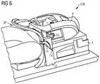
- FIG. 6shows, in a perspective drawing, a side view of one embodiment of a head/neck local coil with a patient in the head/neck local coil, in a non-tilted, flat state;
- FIG. 7shows, in a perspective drawing, a side view of one embodiment of a head/neck local coil with a patient in the head/neck local coil, in a non-tilted flat state;
- FIG. 8shows, in a perspective drawing, a side view of one embodiment of a head/neck local coil with a patient in the head/neck local coil, in a tilted oblique state;
- FIG. 9shows, in a perspective drawing, a top view of one embodiment of a head/neck local coil with a patient in the head/neck local coil, in a tilted oblique state;
- FIG. 10shows, in a perspective drawing, a side view of one embodiment of a head/neck local coil with a patient in the head/neck local coil
- FIG. 11shows one embodiment of a magnetic resonance imaging (MRI) system.
- MRImagnetic resonance imaging
- FIG. 11shows a magnetic resonance imaging (MRI) device 101 (e.g., situated in a shielded room or Faraday cage F) with a whole body coil 102 with, for example, a tubular space 103 in which a patient couch 3 with a body of, for example, an examination object 13 (e.g., of a patient; with or without local coil arrangement 106 ) may be displaced in the direction of the arrow z in order to generate recordings of the patient 13 by an imaging method.
- the local coil arrangement 106is arranged on the patient.
- a local regione.g., field of view (FOV)
- Signals of the local coil arrangement 106may be evaluated (e.g., converted into images, stored or displayed) by an evaluation device (e.g., including elements 168 , 115 , 117 , 119 , 120 , 121 , etc.) of the MRI 101 , which may be connected to the local coil arrangement 106 using, for example, coaxial cables or by radio link (e.g., element 167 ).
- an evaluation devicee.g., including elements 168 , 115 , 117 , 119 , 120 , 121 , etc.
- radio linke.g., element 167
- an MRI device 101In order to use an MRI device 101 to examine a body 13 (e.g., an examination object or a patient) using magnetic resonance imaging, different magnetic fields that are precisely matched to one another in terms of temporal and spatial characteristics are radiated onto the body 13 .
- a strong magnete.g., a cryomagnet 107
- a measurement cabin with an opening 103that is, for example, tunnel-shaped generates a strong static main magnetic field B 0 that has a strength of, for example, 0.2 Tesla to 3 Tesla or more.
- a body 13 to be examinedis, while supported by a patient couch 3 , driven into a region of the main magnetic field B 0 that is approximately homogeneous in the observation region FoV.
- the nuclear spins of atomic nuclei of the body 13are excited by magnetic radiofrequency excitation pulses B 1 ( x, y, z, t ) that are radiated in by a radiofrequency antenna (and/or, optionally, a local coil arrangement) that is depicted in FIG. 11 in a simplified manner as body coil 108 (e.g., multi-part body coil 108 a , 108 b , 108 c ).
- radiofrequency excitation pulsesare generated by a pulse generation unit 109 that is controlled by a pulse sequence control unit 110 .
- the radiofrequency excitation pulsesare conducted to the radiofrequency antenna 108 .
- the radiofrequency system shown in FIG. 11is merely indicated schematically. In a magnetic resonance imaging device 101 , more than one pulse generation unit 109 , more than one radiofrequency amplifier 111 , and a plurality of radiofrequency antennas 108 a, b, c may be used.
- the magnetic resonance imaging device 101also includes gradient coils 112 x , 112 y , 112 z , by which magnetic gradient fields B G (x, y, z, t) are radiated in during a measurement for selective slice excitation and for spatial encoding of the measurement signal.
- the gradient coils 112 x , 112 y , 112 zare controlled by a gradient coil control unit 114 and, optionally, via amplifiers Vx, Vy, Vz that, like the pulse generation unit 109 , is connected to the pulse sequence control unit 110 .
- Signals emitted by the excited nuclear spinsare received by the body coil 108 and/or at least one local coil arrangement 106 , amplified by associated radiofrequency preamplifiers 116 and processed further and digitized by a reception unit 117 .
- the recorded measurement datais digitized and stored as complex numbers in a k-space matrix.
- An associated MR imagemay be reconstructed from the k-space matrix filled with values by a multidimensional Fourier transform.
- the correct signal transmissionis regulated by an upstream transmission/reception switch 118 .
- An image processing unit 119generates an image from the measurement data.
- the imageis displayed to a user using an operating console 120 , and/or the image is stored in a storage unit 121 .
- a central computer unit 122controls the individual installation components.
- images with a high signal-to-noise ratiomay be recorded using local coils (e.g., coils).
- the local coilsare antenna systems that are attached in the direct vicinity on (e.g., anterior) or under (e.g., posterior) the patient.
- the excited nucleiinduce a voltage in the individual antennas of the local coil.
- the induced voltageis then amplified using a low-noise preamplifier (e.g., LNA, preamp) and transmitted by cables to the reception electronics.
- LNAlow-noise preamplifier
- high-field installationse.g., 1.5 T to 12 T and more are used.
- a switching matrix(e.g., RCCS), for example, is installed between reception antennas and receivers.
- the matrixroutes the currently active reception channels (e.g., the reception channels that currently lie in the field of view of the magnet) to the available receivers.
- more local coil elements than receivers are availablemay be connected because, in the case of a whole body cover, local coils that are situated in the FoV or in a homogeneous volume of the magnet may be read out.
- an antenna systemthat may include one or more antenna elements (e.g., coil elements; array coil) is referred to as “coil” or “local coil”. These individual antenna elements may be embodied as loop antennas (e.g., loops), butterfly coils or saddle coils.
- a local coilincludes the coil elements, the preamplifier, further electronics (e.g., standing wave traps) and wiring, the housing and may include a cable with plug, by which the local coil is connected to the MR installation.
- a receivere.g., RX attached to the installation side filters and digitizes signals received from the local coil and transmits the data to the digital signal processing device.
- the digital signal processing devicemay derive an image or spectrum from the measurement and makes the image or spectrum available to the user for the diagnosis.
- Head coils or combined head/neck local coilsare embodied in a tiltable manner for improving the patient comfort or for supporting patients with pathological changes of the cervical spine (e.g., ankylosing spondylitis, torticollis, etc.).
- pathological changes of the cervical spinee.g., ankylosing spondylitis, torticollis, etc.
- a gap SP between the chest of a patient and a strap of the head/neck local coile.g., from the position in FIG. 2 to the position in FIG. 3
- the contoure.g., a strap
- the neck coilmay collide with the chest of the patient or restrict the freedom of movement of the chest.
- high channel head/neck coilsIn order to rest close to the patient, high channel head/neck coils have small dimensions, which may promote collisions at this point or restrictions in the freedom of movement.
- a head/neck local coil(e.g., as depicted in FIG. 1 in a top view, in FIG. 2 in a non-tilted state in a side view, and in FIG. 3 in a tilted state in a side view) may not be tilted or may only be tilted a little.
- Known flexible neck coilsmay also have a movable flexible flap that may only have partial neck covering, and the position of the flexible flap may be reproducible to a restricted extent in a plurality of measurements that are offset in time.
- the flexible flapsmay rest against the patient and may be moved by the patient. Respiratory and body movements may directly influence a generated image.
- FIGS. 4 to 10illustrate details of exemplary embodiments of head/neck local coils according to one or more of the present embodiments (e.g., local coils enabling an MRI examination of head and neck of a patient).
- a combined head/neck local coil 106that includes a rigid height-adjustable neck part 5 and a movable neck part 7 , 8 , 9 (e.g., with a strap 8 remaining at approximately constant height y).
- the rigid (e.g., inherently rigid), height adjustable neck part(e.g., also the movable neck part; the strap 8 of the movable neck part) is automatically adjusted (K*) (e.g., in the vertical direction y, for compensating the tilting movement K) when the head/neck local coil is tilted (K).
- the head/neck local coil 106may be a “directly plugged” local coil 106 , because the local coil 106 is directly plugged into a patient table 3 (e.g., by plugging the connector of the local coil 106 into a plug or a socket on the patient table 3 ).
- the patent application DE 10 2011 079 565.0describes how a directly plugged local coil may be tilted despite a mechanically secured connection to a patient table (e.g., fixed in terms of a position on the patient table).
- a head/neck local coil 106includes, for example, a head/neck local coil lower part 1 that is tiltable (e.g., in relation to a base lower part 2 ) and the base lower part 2 , which may be placed onto a patient couch 3 .
- the base lower part 2establishes electrical contact with the patient couch 3 when directly plugging the local coil 106 .
- the head/neck local coil lower part 1which may be tiltable by a tilting movement (e.g., as indicated by the arrow K), and the base lower part 2 are movable in relation to one another and thereby generate tilting of the local coil (e.g., with respect to a description and exemplary embodiments, see also U.S. Patent Application Publication No. 20130184563, which is hereby incorporated by reference in its entirety).
- the local coil 106includes a head upper part 4 , which, for example, also includes a part 5 of the neck coil that is immobile in relation to the head upper part 4 (e.g., the part 5 of the neck coil that is stationary in relation to the head upper part 4 ).
- the movable neck part 7 , 8 , 9 of the neck coilis attached to the stationary neck part 5 (e.g., optionally also with antennas for imaging the neck).
- the movable neck part 7 , 8 , 9includes a plurality of rigid parts that are mounted in a rotatable manner with respect to one another; in this case, this includes a tilting part 7 , a rigid strap 8 and pushing parts 9 . All or individual ones of these parts 7 , 8 , 9 may in each case include antenna elements and/or electronic components.
- the tilting part 7is mounted in a rotatable manner on the immobile part 5 of the neck coil by a rotary joint 6 .
- the rigid neck strap 8is mounted in a rotatable manner on the tilting part 7 by the rotary joint 10 .
- the lower ends of the rigid neck strap 8are, on both sides of the local coil 106 , connected in a rotatable manner to the pushing parts using the rotary joints 11 .
- the pushing parts 9may move (e.g., vertically) along the linear guide 12 , which is fastened to the stationary neck part 5 and hence also to the head upper part 4 (e.g., the head receiving part of the local coil 106 , in which a head KO of a patient is intended to be situated).
- the base lower part 2is positioned on the patient couch 3 .
- a patient 13is placed in the local coil 106 , which may already be tilted (e.g., as in FIGS. 8-10 ) or may be non-tilted (as in FIGS. 4-7 ).
- the local coil 106may remain flat (e.g., non-tilted) on the patient couch 3 in the case of most patients 13 .
- the head/neck local coil lower part 1(or a part of the head/neck local coil lower part 1 and the immobile and movable neck parts 7 , 8 , 9 together) may be tilted before laying down the patients 13 .
- the head/neck local coil lower part 1may also be tilted with patients 13 .
- each of the pushing parts 9includes a stud 14 . If the complete local coil upper part (e.g., element 4 , elements 4 - 9 ) is placed onto the head/neck local coil lower part 1 , the studs 14 are incident on both sides on the guide edges 15 that are integrated in the immobile base lower part 2 .
- the studs 14are displaced along the guide edges 15 (e.g., in the direction of the arrow P) depending on the tilting angle (e.g., in the direction K) of the local coil.
- the studs 14transmit the movement to the pushing parts 9 , which are pressed upward on the linear guides 12 .
- the pushing parts 9likewise push the rigid neck strap 8 , mounted thereon in a rotatable manner by the rotary joints 11 , upward.
- the tilting part 7mounted by the rotary joints (e.g., elements 6 and 10 , on both sides on the tilting part 7 ), is likewise tilted upward (e.g., in the direction of the arrow and the y-axis).
- the tilting K of the head coilmay be continuous, where the neck coil may open together with each degree of the tilting of the head/neck local coil lower part 1 .
- the automatic coupling of the tilting movementsmay be switched off”: the studs 14 on the pushing parts 9 include a compression spring and latch into the pushing parts 9 in an interlocking manner as a result of pressure and a slight rotation (e.g., approximately 10°). In the latched state, the studs 14 no longer protrude and do not impact on the guide edges 15 when putting on the complete local coil upper part 4 - 9 .
- the described mechanism for adjusting the size of the neck part 7 , 8 , 9(e.g., by tilting the strap 8 is not activated.
- the studs 14are slightly rotated, the interlock disengages, and the compression springs press the studs 14 out again.
- this processis only possible, for example, in the non-tilted initial position (e.g., as in FIGS. 4-7 ) of the head/neck local coil lower part 1 when the upper part is placed on the head/neck local coil lower part 1 (e.g., with/without 4-9) or possible at any time on the separate upper part 4 (e.g., not placed onto the head/neck local coil lower part 1 ).
- an embodimentrelates to a head/neck local coil 106 with a tilting function (K) and an automatically coupled (e.g., by tilting K* at least one strap 8 opposite to the tilting direction K of the upper part for compensating the upper part) and/or size-adjustable neck coil part (e.g., elements 7 , 8 , 9 ).
- Ktilting function
- An enlargement of the neck opening (e.g., in the form of a gap SP between patient and strap 8 ) of the local coil 106may allow for a larger clear space for the patient (e.g., gap SP).
- Subdividing the neck coil into rigid parts (e.g., elements 5 , 7 , 8 and 9 ) that are mounted in a rotatable manner with respect to one another using rotary joints (e.g., elements 6 , 10 and 11 )allows the implementation of a geometrically constant connection (e.g., of the strap at the constant position thereof) to the head coil (e.g., element decoupling).
- the neck coilmay be dimensioned such that there is no contact between the strap 8 of the neck coil and the patient 13 in the non-tilted initial position (e.g., in accordance with FIGS. 4-7 ) so that no movement artifacts are caused.
- Direct coupling of the tilting movement K of the head/neck local coil lower part 1 with the movable neck coil(e.g., with a tilting movement K* on the movable neck coil) may be provided.
- a drive of the movement of the neck strap 8may be provided by studs 14 and guide edges 15 .
- Continuous setting of the movementmay be provided.
- Spring-mounted pickup studs 14may “switch off” the coupling between the movements via the studs being pressed and latched in.
- Preventing a collision between patient and neck coil in the tilted state of the head/neck local coilmay avoid movement artifacts during an imaging MRI measurement.
- An advantagemay lie in good reproducibility of examinations by a coupled movement.
- the guide length of the linear guide of 12 with the pushing parts 9may be dimensioned such that there is freedom from jamming.
Landscapes
- Physics & Mathematics (AREA)
- Health & Medical Sciences (AREA)
- Condensed Matter Physics & Semiconductors (AREA)
- General Physics & Mathematics (AREA)
- Life Sciences & Earth Sciences (AREA)
- Nuclear Medicine, Radiotherapy & Molecular Imaging (AREA)
- High Energy & Nuclear Physics (AREA)
- Biophysics (AREA)
- Heart & Thoracic Surgery (AREA)
- Veterinary Medicine (AREA)
- Public Health (AREA)
- Pathology (AREA)
- Engineering & Computer Science (AREA)
- Biomedical Technology (AREA)
- Radiology & Medical Imaging (AREA)
- Medical Informatics (AREA)
- Molecular Biology (AREA)
- Surgery (AREA)
- Animal Behavior & Ethology (AREA)
- General Health & Medical Sciences (AREA)
- Optics & Photonics (AREA)
- Spectroscopy & Molecular Physics (AREA)
- Magnetic Resonance Imaging Apparatus (AREA)
Abstract
Description
Claims (18)
Applications Claiming Priority (3)
| Application Number | Priority Date | Filing Date | Title |
|---|---|---|---|
| DE102013216861 | 2013-08-23 | ||
| DE102013216861.6ADE102013216861B4 (en) | 2013-08-23 | 2013-08-23 | Head / neck local coil with automatically adjustable neck area when tilting the head / neck local coil |
| DEDE102013216861.6 | 2013-08-23 |
Publications (2)
| Publication Number | Publication Date |
|---|---|
| US20150057528A1 US20150057528A1 (en) | 2015-02-26 |
| US10564234B2true US10564234B2 (en) | 2020-02-18 |
Family
ID=52446824
Family Applications (1)
| Application Number | Title | Priority Date | Filing Date |
|---|---|---|---|
| US14/466,999Expired - Fee RelatedUS10564234B2 (en) | 2013-08-23 | 2014-08-23 | Head/neck local coil with a neck region with automatic size adjustment when tilting the head/neck local coil |
Country Status (2)
| Country | Link |
|---|---|
| US (1) | US10564234B2 (en) |
| DE (1) | DE102013216861B4 (en) |
Families Citing this family (16)
| Publication number | Priority date | Publication date | Assignee | Title |
|---|---|---|---|---|
| DE102011079575B4 (en)* | 2011-07-21 | 2013-11-07 | Siemens Aktiengesellschaft | Bechterew adapter for direct connection head coil with adjustable tilt angle |
| DE102015201319A1 (en)* | 2015-01-27 | 2016-07-28 | Siemens Healthcare Gmbh | Magnetic resonance coil device with a posterior coil unit and a method for the production thereof |
| CN106872918B (en)* | 2017-04-01 | 2024-05-24 | 北京大学第三医院(北京大学第三临床医学院) | MRI local coil base, local coil assembly and ankle coil assembly |
| DE102017210422A1 (en) | 2017-06-21 | 2018-12-27 | Siemens Healthcare Gmbh | MR coil arrangement with adaptive coil spacing layer |
| DE102017221036A1 (en) | 2017-11-24 | 2019-05-29 | Siemens Healthcare Gmbh | A conforming local coil array for magnetic resonance applications |
| EP3594706A1 (en) | 2018-07-13 | 2020-01-15 | Siemens Healthcare GmbH | Flexible local coil with markers and image obtaining method |
| DE202018003431U1 (en) | 2018-07-23 | 2018-08-21 | Siemens Healthcare Gmbh | Interface for high-frequency applications |
| DE102018216365A1 (en) | 2018-09-25 | 2020-03-26 | Siemens Healthcare Gmbh | Wrapping for an MR local coil |
| DE202018004605U1 (en) | 2018-10-04 | 2018-10-26 | Siemens Healthcare Gmbh | Spool carrier for a magnetic resonance imaging and magnetic resonance tomograph |
| DE102018218380A1 (en) | 2018-10-26 | 2020-04-30 | Siemens Healthcare Gmbh | Multi-layer MR local coil |
| US11397229B2 (en) | 2019-03-14 | 2022-07-26 | Shanghai United Imaging Healthcare Co., Ltd. | Local coil apparatus for magnetic resonance imaging |
| DE102019203628B4 (en) | 2019-03-18 | 2023-01-12 | Siemens Healthcare Gmbh | Improved edge MR local coil, associated tooling and method of manufacture |
| EP3966581B1 (en)* | 2019-05-06 | 2024-07-10 | Koninklijke Philips N.V. | Rf coil assembly and mri apparatus |
| US11085978B2 (en) | 2019-06-07 | 2021-08-10 | Synaptive Medical Inc. | Orthogonal element decoupling for moveable coil arrays in MRI |
| JP7352493B2 (en)* | 2020-03-05 | 2023-09-28 | 富士フイルムヘルスケア株式会社 | Head coil device and magnetic resonance imaging device using the same |
| CA3212270A1 (en)* | 2022-09-12 | 2024-03-19 | Synaptive Medical Inc. | Head coil system and methods |
Citations (6)
| Publication number | Priority date | Publication date | Assignee | Title |
|---|---|---|---|---|
| DE102004052943A1 (en) | 2003-11-04 | 2005-06-23 | General Electric Co. | Integrated cervical-thoracic-lumbar-spinal column MRI array coil has rear array, frontal torso array, frontal head-neck-upper chest area array, head section attached to rear array, neck-upper breast region section joined to head section |
| US6980002B1 (en) | 2002-11-04 | 2005-12-27 | General Electric Company | Integrated cervical-thoracic-lumbar spine MRI array coil |
| US20110260728A1 (en)* | 2010-04-23 | 2011-10-27 | Stephan Biber | Magnetic resonance coil device |
| US20120286784A1 (en)* | 2011-05-06 | 2012-11-15 | Daniel Driemel | Size-adjustable head/neck mr surface coil with hinged upper section |
| DE102011079565A1 (en) | 2011-07-21 | 2013-01-24 | Siemens Ag | Head coil for magnetic resonance imaging apparatus, has lower part and upper part that is positioned over lower part, where lower part has lower part-base and lower part-head-bearing-part that is movable relative to lower part-base |
| US20130023756A1 (en)* | 2011-07-21 | 2013-01-24 | Siemens Aktiengesellschaft | Adapter for a direct-connection head coil with adjustable tilt angle |
- 2013
- 2013-08-23DEDE102013216861.6Apatent/DE102013216861B4/enactiveActive
- 2014
- 2014-08-23USUS14/466,999patent/US10564234B2/ennot_activeExpired - Fee Related
Patent Citations (8)
| Publication number | Priority date | Publication date | Assignee | Title |
|---|---|---|---|---|
| US6980002B1 (en) | 2002-11-04 | 2005-12-27 | General Electric Company | Integrated cervical-thoracic-lumbar spine MRI array coil |
| DE102004052943A1 (en) | 2003-11-04 | 2005-06-23 | General Electric Co. | Integrated cervical-thoracic-lumbar-spinal column MRI array coil has rear array, frontal torso array, frontal head-neck-upper chest area array, head section attached to rear array, neck-upper breast region section joined to head section |
| US20110260728A1 (en)* | 2010-04-23 | 2011-10-27 | Stephan Biber | Magnetic resonance coil device |
| US20120286784A1 (en)* | 2011-05-06 | 2012-11-15 | Daniel Driemel | Size-adjustable head/neck mr surface coil with hinged upper section |
| DE102011079565A1 (en) | 2011-07-21 | 2013-01-24 | Siemens Ag | Head coil for magnetic resonance imaging apparatus, has lower part and upper part that is positioned over lower part, where lower part has lower part-base and lower part-head-bearing-part that is movable relative to lower part-base |
| US20130023756A1 (en)* | 2011-07-21 | 2013-01-24 | Siemens Aktiengesellschaft | Adapter for a direct-connection head coil with adjustable tilt angle |
| DE102011079575A1 (en) | 2011-07-21 | 2013-01-24 | Siemens Aktiengesellschaft | Bechterew adapter for direct connection head coil with adjustable tilt angle |
| US20130184563A1 (en) | 2011-07-21 | 2013-07-18 | Siemens Aktiengesellschaft | Direct connection head coil having height adjustment |
Non-Patent Citations (1)
| Title |
|---|
| German Office Action dated Apr. 14, 2014 in corresponding German Patent Application No. DE 10 2013 216 861.6 with English translation. |
Also Published As
| Publication number | Publication date |
|---|---|
| US20150057528A1 (en) | 2015-02-26 |
| DE102013216861A1 (en) | 2015-02-26 |
| DE102013216861B4 (en) | 2016-06-02 |
Similar Documents
| Publication | Publication Date | Title |
|---|---|---|
| US10564234B2 (en) | Head/neck local coil with a neck region with automatic size adjustment when tilting the head/neck local coil | |
| US9138164B2 (en) | Direct connection head coil having height adjustment | |
| US10545203B2 (en) | Head-neck coil with tilting function | |
| US9285440B2 (en) | Size-adjustable head/neck MR surface coil with hinged upper section | |
| US9250302B2 (en) | Adapter for a direct-connection head coil with adjustable tilt angle | |
| US8901929B2 (en) | D-shaped coil | |
| US9035654B2 (en) | Mechanically flexible magnetic resonance coil with opening conductor structures | |
| US10004423B2 (en) | Local coil and leveling mirror | |
| US9841473B2 (en) | MR surface coil with integrated automatic patient immobilization | |
| US20120153956A1 (en) | Mr coil with movable antenna elements | |
| US9194924B2 (en) | MRT local coil | |
| US9547055B2 (en) | Identifying the static position of transmission/reception coils of a magnetic resonance imaging scanner with the aid of electronically readable labels | |
| US20150022208A1 (en) | Use of a Plurality of TX Coils | |
| US9903897B2 (en) | Identifying transmission/reception coils of a magnetic resonance imaging scanner with the aid of electronically readable labels | |
| US9678181B2 (en) | Automatic positioning and adaptation in an adjustment for a shim field map | |
| US20150025362A1 (en) | Local Transmission Coils and Transmission Coil Arrays for Spinal Column Imaging in an MRI Device | |
| US10379178B2 (en) | Tiltable head coil | |
| CN102809735A (en) | Design of shoulder coil having upper components and/or dependent on selection of supporting elements | |
| US20150025361A1 (en) | Breast Coil with a Mechanical Height Adjustment | |
| CN105044633B (en) | Knee coil | |
| US9700231B2 (en) | Holder for double loop coil for MCP images | |
| US8947088B2 (en) | MR slide coil | |
| US20130211241A1 (en) | Local Coil System | |
| US20130162252A1 (en) | Mr hf coils having flexibility that can be modulated | |
| US9671476B2 (en) | Application of a multichannel coil for hand imaging |
Legal Events
| Date | Code | Title | Description |
|---|---|---|---|
| AS | Assignment | Owner name:SIEMENS AKTIENGESELLSCHAFT, GERMANY Free format text:ASSIGNMENT OF ASSIGNORS INTEREST;ASSIGNOR:DRIEMEL, DANIEL;REEL/FRAME:035081/0943 Effective date:20140910 | |
| STPP | Information on status: patent application and granting procedure in general | Free format text:RESPONSE TO NON-FINAL OFFICE ACTION ENTERED AND FORWARDED TO EXAMINER | |
| STPP | Information on status: patent application and granting procedure in general | Free format text:NON FINAL ACTION MAILED | |
| STPP | Information on status: patent application and granting procedure in general | Free format text:NOTICE OF ALLOWANCE MAILED -- APPLICATION RECEIVED IN OFFICE OF PUBLICATIONS | |
| STPP | Information on status: patent application and granting procedure in general | Free format text:PUBLICATIONS -- ISSUE FEE PAYMENT VERIFIED | |
| STCF | Information on status: patent grant | Free format text:PATENTED CASE | |
| AS | Assignment | Owner name:SIEMENS HEALTHCARE GMBH, GERMANY Free format text:ASSIGNMENT OF ASSIGNORS INTEREST;ASSIGNOR:SIEMENS AKTIENGESELLSCHAFT;REEL/FRAME:052653/0131 Effective date:20200415 | |
| FEPP | Fee payment procedure | Free format text:MAINTENANCE FEE REMINDER MAILED (ORIGINAL EVENT CODE: REM.); ENTITY STATUS OF PATENT OWNER: LARGE ENTITY | |
| AS | Assignment | Owner name:SIEMENS HEALTHINEERS AG, GERMANY Free format text:ASSIGNMENT OF ASSIGNORS INTEREST;ASSIGNOR:SIEMENS HEALTHCARE GMBH;REEL/FRAME:066088/0256 Effective date:20231219 | |
| AS | Assignment | Owner name:SIEMENS HEALTHINEERS AG, GERMANY Free format text:CORRECTIVE ASSIGNMENT TO CORRECT THE ASSIGNEE PREVIOUSLY RECORDED AT REEL: 066088 FRAME: 0256. ASSIGNOR(S) HEREBY CONFIRMS THE ASSIGNMENT;ASSIGNOR:SIEMENS HEALTHCARE GMBH;REEL/FRAME:071178/0246 Effective date:20231219 | |
| LAPS | Lapse for failure to pay maintenance fees | Free format text:PATENT EXPIRED FOR FAILURE TO PAY MAINTENANCE FEES (ORIGINAL EVENT CODE: EXP.); ENTITY STATUS OF PATENT OWNER: LARGE ENTITY | |
| STCH | Information on status: patent discontinuation | Free format text:PATENT EXPIRED DUE TO NONPAYMENT OF MAINTENANCE FEES UNDER 37 CFR 1.362 | |
| FP | Lapsed due to failure to pay maintenance fee | Effective date:20240218 |