US10564186B2 - Current sense amplifier architecture and level shifter - Google Patents
Current sense amplifier architecture and level shifterDownload PDFInfo
- Publication number
- US10564186B2 US10564186B2US15/712,771US201715712771AUS10564186B2US 10564186 B2US10564186 B2US 10564186B2US 201715712771 AUS201715712771 AUS 201715712771AUS 10564186 B2US10564186 B2US 10564186B2
- Authority
- US
- United States
- Prior art keywords
- amplifier
- voltage
- coupled
- high voltage
- low voltage
- Prior art date
- Legal status (The legal status is an assumption and is not a legal conclusion. Google has not performed a legal analysis and makes no representation as to the accuracy of the status listed.)
- Active, expires
Links
- 239000003990capacitorSubstances0.000claimsabstractdescription14
- 230000008878couplingEffects0.000claimsdescription31
- 238000010168coupling processMethods0.000claimsdescription31
- 238000005859coupling reactionMethods0.000claimsdescription31
- 238000000034methodMethods0.000claimsdescription12
- 238000005259measurementMethods0.000claimsdescription5
- 238000010586diagramMethods0.000description11
- 238000009966trimmingMethods0.000description5
- 230000008901benefitEffects0.000description3
- 230000007423decreaseEffects0.000description3
- 238000013461designMethods0.000description3
- 238000013459approachMethods0.000description2
- 230000001934delayEffects0.000description2
- 230000006872improvementEffects0.000description2
- 238000012986modificationMethods0.000description2
- 230000004048modificationEffects0.000description2
- RYGMFSIKBFXOCR-UHFFFAOYSA-NCopperChemical compound[Cu]RYGMFSIKBFXOCR-UHFFFAOYSA-N0.000description1
- 230000003321amplificationEffects0.000description1
- 230000002457bidirectional effectEffects0.000description1
- 230000008859changeEffects0.000description1
- 239000004020conductorSubstances0.000description1
- 229910052802copperInorganic materials0.000description1
- 239000010949copperSubstances0.000description1
- 238000012937correctionMethods0.000description1
- 230000000694effectsEffects0.000description1
- 238000005516engineering processMethods0.000description1
- 238000007667floatingMethods0.000description1
- 238000012544monitoring processMethods0.000description1
- 238000003199nucleic acid amplification methodMethods0.000description1
- 230000008569processEffects0.000description1
- 230000001360synchronised effectEffects0.000description1
- 239000002699waste materialSubstances0.000description1
Images


Classifications
- G—PHYSICS
- G01—MEASURING; TESTING
- G01R—MEASURING ELECTRIC VARIABLES; MEASURING MAGNETIC VARIABLES
- G01R15/00—Details of measuring arrangements of the types provided for in groups G01R17/00 - G01R29/00, G01R33/00 - G01R33/26 or G01R35/00
- G01R15/14—Adaptations providing voltage or current isolation, e.g. for high-voltage or high-current networks
- G01R15/146—Measuring arrangements for current not covered by other subgroups of G01R15/14, e.g. using current dividers, shunts, or measuring a voltage drop
- G—PHYSICS
- G01—MEASURING; TESTING
- G01R—MEASURING ELECTRIC VARIABLES; MEASURING MAGNETIC VARIABLES
- G01R1/00—Details of instruments or arrangements of the types included in groups G01R5/00 - G01R13/00 and G01R31/00
- G01R1/30—Structural combination of electric measuring instruments with basic electronic circuits, e.g. with amplifier
- G—PHYSICS
- G01—MEASURING; TESTING
- G01R—MEASURING ELECTRIC VARIABLES; MEASURING MAGNETIC VARIABLES
- G01R19/00—Arrangements for measuring currents or voltages or for indicating presence or sign thereof
- G01R19/0023—Measuring currents or voltages from sources with high internal resistance by means of measuring circuits with high input impedance, e.g. OP-amplifiers
- H—ELECTRICITY
- H01—ELECTRIC ELEMENTS
- H01L—SEMICONDUCTOR DEVICES NOT COVERED BY CLASS H10
- H01L23/00—Details of semiconductor or other solid state devices
- H01L23/58—Structural electrical arrangements for semiconductor devices not otherwise provided for, e.g. in combination with batteries
- H01L23/60—Protection against electrostatic charges or discharges, e.g. Faraday shields
- H—ELECTRICITY
- H03—ELECTRONIC CIRCUITRY
- H03F—AMPLIFIERS
- H03F3/00—Amplifiers with only discharge tubes or only semiconductor devices as amplifying elements
- H03F3/20—Power amplifiers, e.g. Class B amplifiers, Class C amplifiers
- H03F3/21—Power amplifiers, e.g. Class B amplifiers, Class C amplifiers with semiconductor devices only
- H03F3/217—Class D power amplifiers; Switching amplifiers
- H03F3/2171—Class D power amplifiers; Switching amplifiers with field-effect devices
- H—ELECTRICITY
- H03—ELECTRONIC CIRCUITRY
- H03F—AMPLIFIERS
- H03F3/00—Amplifiers with only discharge tubes or only semiconductor devices as amplifying elements
- H03F3/38—DC amplifiers with modulator at input and demodulator at output; Modulators or demodulators specially adapted for use in such amplifiers
- H03F3/387—DC amplifiers with modulator at input and demodulator at output; Modulators or demodulators specially adapted for use in such amplifiers with semiconductor devices only
- H03F3/393—DC amplifiers with modulator at input and demodulator at output; Modulators or demodulators specially adapted for use in such amplifiers with semiconductor devices only with field-effect devices
- H—ELECTRICITY
- H03—ELECTRONIC CIRCUITRY
- H03F—AMPLIFIERS
- H03F3/00—Amplifiers with only discharge tubes or only semiconductor devices as amplifying elements
- H03F3/45—Differential amplifiers
- H03F3/45071—Differential amplifiers with semiconductor devices only
- H03F3/45076—Differential amplifiers with semiconductor devices only characterised by the way of implementation of the active amplifying circuit in the differential amplifier
- H03F3/45475—Differential amplifiers with semiconductor devices only characterised by the way of implementation of the active amplifying circuit in the differential amplifier using IC blocks as the active amplifying circuit
- H—ELECTRICITY
- H03—ELECTRONIC CIRCUITRY
- H03F—AMPLIFIERS
- H03F2200/00—Indexing scheme relating to amplifiers
- H03F2200/171—A filter circuit coupled to the output of an amplifier
Definitions
- the present disclosurerelates to current sense circuit architectures, and, more particularly, to high-side current sense circuits with enhanced common-mode rejection ratios (CMRRs) and reduced voltage offsets, and, in addition, to high-voltage level shifters that minimize time delays between high-voltage and low-voltage clocks.
- CMRRscommon-mode rejection ratios
- the ability to sense supply currentsis useful in many electronic systems.
- Current sensingis used in such applications as over-current protection and monitoring of battery charge level, helping maintain desired power levels and to prevent circuit faults and over-discharged batteries.
- One method for determining current(referred to as magnetic sensing) is via measurement of the magnetic field around a current-carrying conductor, but such an approach is costly, not without sources of error, and is limited to AC current measurement.
- Another method of determining current(referred to as resistive sensing) is through placement of a small resistor in the current path, and measurement of the voltage drop across the resistor.
- a small voltage drop across a “current-sense” resistor (“Rsense”)that is placed in series with the voltage source (e.g., battery), and the load, is measured. If Rsense 506 is connected in series with the “hot wire” (e.g., with the high-voltage power supply), this is referred to as high-side current sensing. Connecting Rsense 506 to ground would be referred to as low-side current sensing.
- the voltage dropcan then be amplified to produce an output signal that is proportional to current.
- the value of Rsense 506should be low to minimize power dissipation in the current sense resistor, but it should be high enough to produce a voltage drop that is detectable by the sensor amplifier.
- a prior art current-sensing circuitincludes a zero-drift operational amplifier 102 and pairs of laser-trimmed resistors 104 for attenuating the input common-mode voltage to within the supply range of the amplifier 102 .
- Common-mode noise in the power supplyis not rejected if there is a difference in the resistance values of the resistors 104 , and the resistors 104 must be precisely matched to balance inputs to the amplifier 102 for achieving a high CMRR.
- Laser trimmingmay be used to precisely match the resistors 104 to each other, and that increases the cost of the integrated circuit die (chip).
- a current sense monitorincludes a zero-drift amplifier 202 , a second amplifier 204 , and a network of capacitors and resistors.
- these capacitors and resistorsmust be precisely matched to achieve high CMRR, something that increases costs.
- the switching of the capacitors, in combination with the RC time constants of the capacitorsincreases settling time (i.e., the time required for voltages to settle), which reduces bandwidth for the circuit (i.e., how rapidly a change in load current could be sensed).
- the network of capacitors and resistorsalso increases package size. Such a circuit is implemented in the Texas Instruments Inc., datasheet for the INA282.
- FIG. 3depicted is a prior art current-feedback instrumentation amplifier for high-side current-sensing with auto-zeroing features.
- This high-side current sensing circuitincludes an instrumentation amplifier with chopping and auto-zeroing circuitry for lowering drift and DC offset.
- this architecturehas greater complexity, higher noise, slower speed and requires a relatively larger die and package size to accommodate the larger number of components.
- Such a circuitis discussed in an article by Witte, Huijsing, & Makinwa, “A Current-Feedback Instrumentation Amplifier with 5 ⁇ V Offset for Bidirectional High-Side Current-Sensing, IEEE Journal of Solid-State Circuits, Vol. 43, No. 12, December 2008.
- a level shifteris useful to translate or shift voltage levels and domains.
- Prior level shifterssuch as the one shown in FIG. 4 , suffer from several drawbacks. For example, they may have a high number of digital latches resulting in higher overshoot currents from high voltage power supplies. They may also have input and output clocks with the same frequency, and only be able to show the result for high-voltage power supplies of, e.g., 10 volts, with no result available for higher voltages.
- the current sense circuit componentsdo not require matching by laser trimming, and can be accommodated on a die for a small integrated circuit package.
- a level shifter with low clock time delay and accurate duty cycleboth of which are important for chopping and other circuit applications such as switching power supplies, motor control, etc.
- a method for providing current measurement with a high side current sensing amplifiermay comprise the steps of: providing a current sensing resistor coupled between a power supply voltage and a load coupled to the power supply through the current sensing resistor; providing a first high voltage amplifier; coupling an operating voltage input of the first high voltage amplifier to the power supply voltage; coupling a non-inverting input of the first high voltage amplifier to the power supply voltage; coupling a low resistance value resistor between the operating voltage input and the non-inverting input of the first high voltage amplifier; and coupling an inverting input of the first high voltage amplifier to the load.
- the methodmay comprise the steps of: providing a first low voltage amplifier; coupling a non-inverting input of the first low voltage amplifier to a reference voltage; coupling an inverting input of the first low voltage amplifier to a feedback voltage; and coupling differential outputs of the first low voltage amplifier to differential outputs of the first high voltage amplifier.
- the methodmay comprise the step of coupling the differential outputs of the first high voltage and first low voltage amplifiers to differential outputs of a third low voltage amplifier.
- the methodmay comprise the step of coupling the differential outputs of the third low voltage amplifier to differential inputs of an operational amplifier output buffer.
- the methodmay comprise the step of providing a chopping circuit, wherein the chopping circuit may comprise: a first chopping switch coupled between the differential inputs of the first high voltage amplifier and differential inputs of a second high voltage amplifier; a second chopping switch coupled between the differential inputs of the first low voltage amplifier and differential inputs of a second low voltage amplifier; a third chopping switch coupled to differential outputs of the second high voltage amplifier and differential outputs of the second low voltage amplifier; wherein the differential outputs of the second high voltage amplifier may be coupled to the differential outputs of the second low voltage amplifier; and a low pass filter coupled between outputs of the third chopping switch and the differential inputs of the third low voltage amplifier.
- the chopping circuitmay comprise: a first chopping switch coupled between the differential inputs of the first high voltage amplifier and differential inputs of a second high voltage amplifier; a second chopping switch coupled between the differential inputs of the first low voltage amplifier and differential inputs of a second low voltage amplifier; a third chopping switch coupled to differential
- the methodmay comprise the steps of providing a high voltage level shifter circuit with a high voltage clock output, wherein the high voltage level shifter circuit may comprise the steps of: providing a low voltage oscillator circuit operating at N-times a chopping frequency, where N may be equal to or greater than two (2); and proving a high voltage divide-by-N circuit having an input coupled to the low voltage oscillator circuit and providing a high voltage clock output at the chopping frequency; wherein one edge of the low voltage oscillator circuit may be used to regenerate the high voltage clock output.
- an amplifier architecture fabricated on an integrated circuit (IC) diecomprising: a first IC die pad adapted for coupling to a power supply voltage and coupled to an operating voltage input (VDDHV) of an amplifier; a second die pad adapted for coupling to the power supply voltage and coupled to a non-inverting input (VIP) of the amplifier; a third die pad coupled to an inverting input (VIM) of the amplifier and adapted for coupling to a sense resistor coupled to a load, wherein the sense resistor may be coupled between the power supply voltage and the load; and a resistor (Rs) may be fabricated on the IC die and coupled between the first and second die pads, whereby induced voltage offset of the amplifier may be reduced.
- VDDHVoperating voltage input
- VDDHVoperating voltage input
- VDDHVoperating voltage input
- VDDHVoperating voltage input
- VDDHVoperating voltage input
- VDDHVoperating voltage input
- VDDHVoperating voltage input
- VDDHVoperating voltage input
- the amplifier architecturemay be adapted for use in any self-correcting offset system, such as auto-zero and chopper stabilized circuits.
- the amplifier architecturemay comprise a single electrostatic discharge (ESD) circuit coupled to the second die pad and providing ESD protection for both the operating voltage input and the non-inverting input of the amplifier.
- ESDelectrostatic discharge
- a current sensing amplifiercomprising: a first high voltage amplifier fabricated on an integrated circuit (IC) die and having an operating voltage input (VDDHV) adapted for coupling to a high voltage supply, a first input (VIP) and a second input (VIM) adapted for coupling to a current sense resistor coupled between the high voltage supply and a load, wherein the first input (VIP) may be coupled to the high voltage supply side of the current sense resistor and the second input (VIM) may be coupled to the load side of the current sense resistor; a resistor (Rs) fabricated on the IC die and coupled between the operating voltage input (VDDHV) and the first input (VIP) of the first high voltage amplifier; a first low voltage amplifier having first and second inputs adapted for coupling to a reference voltage (VREF) and a feedback voltage (VFBK), respectively; and first and second outputs of the first high voltage amplifier may be coupled to first and second outputs, respectively, of the first low voltage amplifier; and
- VDDHV
- a chopping circuitmay be coupled between the first and second inputs of the first high and low voltage amplifiers, and the differential inputs of the operational amplifier output buffer.
- the chopping circuitmay comprise: a first chopping switch coupled between the first and second inputs of the first high voltage amplifier and first and second inputs of a second high voltage amplifier; a second chopping switch coupled between the first and second inputs of the first low voltage amplifier and first and second inputs of a second low voltage amplifier; a third chopping switch coupled to first and second outputs of the second high voltage amplifier and first and second outputs of the second low voltage amplifier; wherein the first and second outputs of the second high voltage amplifier may be coupled to the first and second outputs of the second low voltage amplifier; a low pass filter coupled to first and second outputs of the third chopping switch; and a third low voltage amplifier having first and second inputs coupled to first and second outputs of the low pass filter, and first and second outputs coupled to the first and second outputs of the first high and low voltage amplifiers, respectively.
- the high voltage amplifiersmay be transconductance amplifiers.
- the low voltage amplifiersmay be transconductance amplifiers.
- the low pass filtermay be a switched capacitor low pass filter.
- a high voltage level shifter circuitmay provide a high voltage clock output.
- the high voltage level shifter circuitmay comprise: a low voltage oscillator circuit operating at N-times a chopping frequency, where N may be equal to or greater than two (2); and a high voltage divide-by-N circuit having an input coupled to the low voltage oscillator circuit and providing a high voltage clock output at the chopping frequency; wherein one edge of the low voltage oscillator circuit may be used to regenerate the high voltage clock output.
- an electrostatic discharge protection circuitmay be coupled to the first input of the first high voltage amplifier.
- the first amplifier inputmay be a non-inverting input and the second amplifier input may be an inverting input.
- FIG. 1illustrates a prior art current sense amplifier with a network of laser-trimmed resistors
- FIG. 2illustrates a prior art zero-drift current shunt monitor with a network of precisely-matched resistors and capacitors
- FIG. 3illustrates a prior art current-feedback instrumentation amplifier for high-side current-sensing with auto-zeroing features
- FIG. 4illustrates a prior art high voltage level shifter in a 0.35 ⁇ m HV-CMOS process
- FIG. 5illustrates a schematic block diagram of a high-side current sensing system, according to the teachings of this disclosure
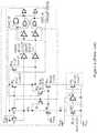
- FIG. 6illustrates a schematic block diagram of a high-side current-sensing architecture, according to a specific example embodiment of the present disclosure
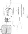
- FIG. 7illustrates a schematic block diagram of an integrated circuit package with a sensing circuit die therein, according to specific example embodiments of the present disclosure
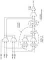
- FIG. 8illustrates a schematic diagram of a high-voltage level shifter having very small signal propagation time delay, according to a specific example embodiment of the present disclosure
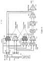
- FIG. 9illustrates a schematic block diagram of the circuit architecture shown in FIG. 6 and the high-voltage level shifter shown in FIG. 8 , according to specific example embodiments of the present disclosure
- FIG. 10illustrates a schematic graph representing the relationship between offset voltage (Vos) in microvolts and resistance values (Rs) in ohms, according to the teachings of the present disclosure.
- FIG. 11illustrates a table of key specifications for the prior art circuits of FIGS. 1 and 2 , and the exemplary architectures of FIGS. 5, 6, and 9 .
- an exemplary voltage sensing architecture of the present disclosureaddresses the above drawbacks as well as others.
- the voltage sensing architecture of the present disclosureis a simplification and improvement over prior art voltage sensing circuits by using chopping only, without requiring auto-zeroing, and by using a simpler (and faster) switched capacitor filter instead of an auto-zeroing integrator filter.
- VIPpositive DC sense node
- VDDHVpower supply
- An exemplary circuit architecture of the present disclosuremay comprise a zero-drift current sensor 502 that may be provided as part of an integrated circuit package (see FIG. 7 ).
- the high-side current sensorWhen installed in an electronic system, the high-side current sensor may be coupled to an external small resistance value resistor, Rsense 506 , that connects a high voltage (HV) power supply (not shown) to a load 504 .
- the output of the sensor 502may be a DC voltage that is proportional to the current through the Rsense 506 .
- This DC sense voltagemay be coupled to an analog-to-digital converter (ADC) in a microcontroller 508 for digitization and interpretation thereof, thereby allowing the power consumed by the load 504 to be measured.
- ADCanalog-to-digital converter
- This DC sense voltagemay be converted from a high-voltage domain to a low-voltage domain, and then coupled to the ADC/microcontroller 508 at this low voltage.
- a lower value resistancemay be used for Rsense 506 , and the power consumed (wasted) by the Rsense 506 may thereby be significantly reduced.
- a zero-drift current sensor circuitmay comprise a first transconductance amplifier 610 , a second transconductance amplifier 612 , a third transconductance amplifier 614 , a fourth transconductance amplifier 616 , a first chopping switch 618 , a second chopping switch 620 , a third chopping switch 622 , a switched capacitor filter 624 , a fifth transconductance amplifier 626 , and an operational amplifier output buffer 628 .
- the first and third amplifiers 610 and 614may comprise high voltage transconductance amplifiers with differential inputs and outputs.
- the second, fourth and fifth amplifiers 612 , 616 and 626may comprise low voltage transconductance amplifiers having differential inputs and outputs.
- the first chopping switch 618may be rated for high voltage operation.
- the low pass filter 624may be a simple switched capacitor low pass filter.
- the chopping switches 618 , 620 and 622inter-exchange the polarity of signals to the inputs of the amplifiers 614 and 616 , and the low pass filter 624 during a chopping operation.
- the VREF and VFBK nodesmay be coupled to a feedback network (not shown) for setting the gain (amplification) of the current sensor circuit 502 .
- the first and third amplifiers 610 and 614comprise a high-voltage section and the second and fourth amplifiers 612 and 616 comprise a low-voltage section of the current sensor circuit 502 .
- the circuit architecture of FIG. 6provides chopping without requiring auto-zeroing, and does not require the auto-zeroing integrator filter which is relatively slower in passing signals.
- a simple switched capacitor filter 624is required to more quickly filter signal ripples resulting from the chopping circuitry and provide a smoother DC output.
- the circuit architecture shown in FIG. 6may achieve an enhanced CMRR without laser trimming of component values, and it reduces power consumption, complexity, noise, and die size.
- FIG. 7depicted is a schematic block diagram of an integrated circuit package with a sensing circuit die therein, according to specific example embodiments of this disclosure.
- the current sensor circuit 502 shown in FIG. 6may be fabricated on an integrated circuit (IC) die 720 and coupled to a connection node 740 (e.g., pad, pin) of an IC package 730 enclosing the IC die 720 .
- a wire w 1having a resistance Rw 1
- wire w 2having a resistance Rw 2
- a low resistance resistor, Rsmay be coupled between the VDDHV and VIP nodes of the IC die 720 .
- only one external connectionis required on the IC package 730 for coupling to the VIP terminal shown in FIG. 6 .
- Interfacing with the IC package 730may be printed circuit board (PCB) components block 750 , representing other electronic components in the electronic system incorporating the IC package 730 .
- PCBprinted circuit board
- the voltage between VIP and VIMis what is sensed by the current sensing circuit 502 .
- VDDHV and VIPare effectively coupled together via a first wire w 1 connecting the VDDHV node of the IC die 720 to the VIP pad 740 , and a second wire w 2 connecting the VIP node of the IC die 720 to the VIP pad 740 .
- Merging the VDDHV and current sensor circuit 502 positive (VIP) inputs into one pad 740helps this circuit fit into smaller packages (such as the SOT-23), but as a consequence, supply current flows into VDDHV. This current flows through wires w 1 and w 2 , and causes a voltage drop. This voltage drop is considered an “input current induced” voltage offset.
- a small resistance value resistor Rsmay be connected internally between the VDDHV and VIP nodes of the IC die 720 . While Rs is in series between the VDDHV and VIP nodes of the IC die 720 , it is connected in parallel with Rw 1 and Rw 2 , the resistances of wires w 1 and w 2 . Adding resistor Rs substantially reduces the offset resulting from the measured input current.
- the IC die 720may also include an “HV ESD” block 742 representing a circuit (which can be in the form of a specialized chip device) intended to protect circuit components against electrostatic discharge (ESD) events.
- HV ESDelectrostatic discharge
- the VDDHV and VIP nodeswere separate, the VDDHV and VIP nodes would each have to be provided with an HV ESD circuit for protection (each of which can require a significant amount of space on the die).
- connecting the VDDHV and VIP nodes together with the low resistance resistor Rsmeans that only one HV ESD circuit is needed, saving space and allowing for a decrease in IC die and package sizes.
- FIG. 10depicted is a schematic graph representing the relationship between offset voltage (Vos) in microvolts and resistance values (Rs) in ohms, according to the teachings of the present disclosure.
- Voffset_inducedThe amount of induced voltage offset (“Voffset_induced”) can be determined using the following equation:
- Voffset_inducedIddHv ⁇ Rw ⁇ ⁇ 1 ⁇ Rw ⁇ ⁇ 2 ( Rw ⁇ ⁇ 1 + Rw ⁇ ⁇ 2 + Rs )
- IddHvis the input current
- Rw 1 and Rw 2are the resistances (in ohms) of the shorting wires w 1 and w 2 , respectively
- Rsis the resistance (in ohms) of Rs.
- the voltage offset in microvoltsdecreases as the value for Rs increases. Without a Rs resistor (e.g., if VDDHV and VIP were shorted and Rs was zero), the offset voltage would be 20 microvolts. If the Rs resistor has a value of three (3) ohms, the offset voltage drops significantly, down to 2.9 microvolts in the graph. It is noted that the resistances Rw 1 and Rw 2 for copper wires w 1 and w 2 would be expected to be about 0.2 ohms each.
- FIG. 8depicted is a schematic diagram of a high-voltage level shifter having very small signal propagation time delay.
- An ultra-low delay high voltage level shifter designutilizes one edge of the low voltage input clock running at twice the high voltage chopping clock operating frequency to regenerate the high voltage clock output. The resulting delay between the low voltage and high voltage chopping clock is very small comparing with the prior art level shifters. Also, this design can work at much higher operating voltage.
- FIG. 8Shown in FIG. 8 is an exemplary high-voltage level shifter circuit, generally represented by the numeral 800 , that provides low clock delay between a low-voltage clock and a high-voltage clock (see FIG. 9 ).
- the low-voltage clockFIG. 9
- the circuitsuch as the chopping circuit
- the high-voltage clockshould track the low-voltage clock, such that they are effectively synchronized with each other. This is particularly useful here because both low delay and accurate duty cycle are critical for chopping circuits.
- Nis equal to or greater than two (2), to achieve very low delay between high voltage and low voltage chopping clocks. Since the high voltage clock is divided by N the 50% duty cycle is guaranteed.
- the very fast falling edge of the clkxN at point “B”may be used to re-generate normal chopping clocks clkhv 1 and clkhv 2 (see system diagram of FIG. 9 ). Because this level shifter consumes no DC current, it is well-suited for use in low power environments.
- FIG. 9depicted is a schematic block diagram of the circuit architecture shown in FIG. 6 and the high-voltage level shifter shown in FIG. 8 , according to specific example embodiments of the present disclosure.
- the current sensor circuit 502is further associated with a low voltage clock oscillator 1030 providing the N times chopping frequency clock signal to an input of the high-voltage level shifter 800 (see FIG. 8 ) that provides the high-voltage chopping frequency clock signal to the current sensor circuit 502 .
- FIG. 11depicted is a table of key specifications for the prior art circuits of FIGS. 1 and 2 , and the exemplary architectures of FIGS. 5, 6, and 9 .
- This tableclearly shows that the exemplary architectures of the present disclosure significantly improve upon key specifications for such circuits.
- the expected bandwidth for the circuit represented in FIG. 1is 150 kHz, with a maximum current consumption of 2.5 mA and a typical CMRR of 105 decibels (dB).
- the typical offsetis expected to be around 100 ⁇ V, with a maximum offset drift of about 1 ⁇ V/° C.
- a suitable packageis the 8-pin MSOP8.
- FIG. 11depicted is a table of key specifications for the prior art circuits of FIGS. 1 and 2 , and the exemplary architectures of FIGS. 5, 6, and 9 .
- This tableclearly shows that the exemplary architectures of the present disclosure significantly improve upon key specifications for such circuits.
- the expected bandwidth for the circuit represented in FIG. 1is 150 kHz, with
- the expected bandwidthis 10 kHz, with a maximum current consumption of 900 ⁇ A and a typical CMRR of 140 B.
- the typical offsetis expected to be around 70 ⁇ V, with a maximum offset drift of 1.5 ⁇ V/° C.
- a suitable packageis the 8-pin SOIC8.
- the exemplary circuit architecture in accordance with this disclosureachieves a dramatically higher bandwidth than prior art approaches at 600 kHz (versus 150 kHz for the one in FIG. 1 and 10 kHz for the one in FIG. 2 ).
- the current consumed by the current-sensing circuit 502is also substantially reduced to a maximum of 750 microamps (as opposed to 2.5 milliamps for the one in FIG. 1 , and 900 microamps for the one in FIG. 2 ).
- the CMRR achievedis expected to be about 143 dB, which is higher than the 105 and 140 dB values for the circuits in FIGS. 1 and 2 , respectively.
- the voltage offsetis dramatically reduced to a maximum of 20 microvolts, from the prior art circuit maximums of 100 and 70 microvolts.
- the offset driftis also lower, down to a maximum of 0.2 microvolts per degree C.
- the improvement on offset driftis mainly due to the dynamic offset correction scheme used by the architecture disclosed herein.
- the package sizeis also reduced to the smaller SOT23 package, rather than the larger MSOP8 for the circuit of FIG. 1 , and SOIC8 for the circuit of FIG. 2 .
- the level shifteris particularly advantageous in the exemplary current-sensing architecture disclosed above because the chopping circuitry in the package of FIG. 9 benefits from lower delays between clocks; consequently, this level shifter enhances performance.
- the level shifter of FIG. 8can be used in other circuits that benefit from level shifters in general.
- the exemplary circuit architectures discussedcombine multiple features to achieve the enhanced specifications discussed above, not all of these features are necessarily required for improved results.
- the VDDHV (high voltage power supply) and VIP pinsmay be merged without the “chopping and/or auto-zeroing” features disclosed herein.
Landscapes
- Engineering & Computer Science (AREA)
- Power Engineering (AREA)
- Physics & Mathematics (AREA)
- General Physics & Mathematics (AREA)
- Condensed Matter Physics & Semiconductors (AREA)
- Computer Hardware Design (AREA)
- Microelectronics & Electronic Packaging (AREA)
- Amplifiers (AREA)
Abstract
Description
In this equation, IddHv is the input current, Rw1 and Rw2 are the resistances (in ohms) of the shorting wires w1 and w2, respectively, and Rs is the resistance (in ohms) of Rs. As can be observed in the equation, increasing the sum of Rw1, Rw2, and Rs (i.e., the denominator) decreases offset voltage because of their inverse relationship. Consequently, as represented in the graphic plot shown in
Claims (14)
Priority Applications (6)
| Application Number | Priority Date | Filing Date | Title |
|---|---|---|---|
| US15/712,771US10564186B2 (en) | 2016-09-23 | 2017-09-22 | Current sense amplifier architecture and level shifter |
| EP17778449.3AEP3516404B1 (en) | 2016-09-23 | 2017-09-25 | Current sense amplifier architecture and level shifter |
| CN201780048411.XACN109564249B (en) | 2016-09-23 | 2017-09-25 | Current sense amplifier architecture and level shifter |
| KR1020197003672AKR20190058454A (en) | 2016-09-23 | 2017-09-25 | Current Sense Amplifier Architecture and Level Shifter |
| TW106132795ATW201825909A (en) | 2016-09-23 | 2017-09-25 | Current sense amplifier architecture and level shifter |
| PCT/US2017/053158WO2018058010A1 (en) | 2016-09-23 | 2017-09-25 | Current sense amplifier architecture and level shifter |
Applications Claiming Priority (2)
| Application Number | Priority Date | Filing Date | Title |
|---|---|---|---|
| US201662399025P | 2016-09-23 | 2016-09-23 | |
| US15/712,771US10564186B2 (en) | 2016-09-23 | 2017-09-22 | Current sense amplifier architecture and level shifter |
Publications (2)
| Publication Number | Publication Date |
|---|---|
| US20180088152A1 US20180088152A1 (en) | 2018-03-29 |
| US10564186B2true US10564186B2 (en) | 2020-02-18 |
Family
ID=61686079
Family Applications (1)
| Application Number | Title | Priority Date | Filing Date |
|---|---|---|---|
| US15/712,771Active2038-04-26US10564186B2 (en) | 2016-09-23 | 2017-09-22 | Current sense amplifier architecture and level shifter |
Country Status (6)
| Country | Link |
|---|---|
| US (1) | US10564186B2 (en) |
| EP (1) | EP3516404B1 (en) |
| KR (1) | KR20190058454A (en) |
| CN (1) | CN109564249B (en) |
| TW (1) | TW201825909A (en) |
| WO (1) | WO2018058010A1 (en) |
Families Citing this family (10)
| Publication number | Priority date | Publication date | Assignee | Title |
|---|---|---|---|---|
| TWI670932B (en)* | 2019-02-12 | 2019-09-01 | 財團法人國家實驗研究院 | Signal process circuit |
| CN110018337B (en)* | 2019-04-24 | 2021-03-16 | 上海类比半导体技术有限公司 | Bidirectional sampling circuit, sampling method and testing method thereof |
| US11829168B2 (en)* | 2019-12-08 | 2023-11-28 | Qualcomm Incorporated | Power management circuit including on-board current-sense resistor and on-die current sensor |
| GB2595546B (en)* | 2020-04-23 | 2022-04-20 | Cirrus Logic Int Semiconductor Ltd | Current sensing circuitry |
| US11448670B2 (en)* | 2020-12-23 | 2022-09-20 | Hamilton Sundstrand Corporation | Overcurrent detection using dissimilar biasing of diode networks |
| CN113225024B (en)* | 2021-03-25 | 2022-09-06 | 南京邮电大学 | A Low Noise Voltage Amplification and Conditioning Circuit for High Resistance Source Measurement |
| CN113219233B (en)* | 2021-04-30 | 2023-06-09 | 石家庄宇飞电子有限公司 | Voltage expansion circuit for high-side current sampling |
| JP7700005B2 (en)* | 2021-09-14 | 2025-06-30 | 日清紡マイクロデバイス株式会社 | Semiconductor Device |
| CN114740254A (en)* | 2022-05-07 | 2022-07-12 | 四川钧力能源科技有限公司 | A precision voltage monitoring circuit suitable for high voltage |
| US20240230720A1 (en)* | 2023-01-05 | 2024-07-11 | Mediatek Inc. | Detection device and detection method |
Citations (15)
| Publication number | Priority date | Publication date | Assignee | Title |
|---|---|---|---|---|
| US5920264A (en)* | 1994-06-08 | 1999-07-06 | Samsung Electronics Co., Ltd. | Computer system protection device |
| US20060176108A1 (en)* | 2005-02-08 | 2006-08-10 | Huijsing Johan H | Frequency stabilization of chopper-stabilized amplifiers |
| US20060176109A1 (en)* | 2005-02-08 | 2006-08-10 | Huijsing Johan H | Chopper chopper-stabilized instrumentation and operational amplifiers |
| US7098733B1 (en)* | 2004-07-21 | 2006-08-29 | Linear Technology Corporation | Methods and circuits for selectable gain amplification by subtracting gains |
| US7535295B1 (en)* | 2006-09-15 | 2009-05-19 | Maxim Integrated Products, Inc. | Chopper stabilized amplifiers combining low chopper noise and linear frequency characteristics |
| US20090174479A1 (en)* | 2008-01-04 | 2009-07-09 | Texas Instruments Incorporated | High-voltage differential amplifier and method using low voltage amplifier and dynamic voltage selection |
| US20100039118A1 (en) | 2005-09-07 | 2010-02-18 | Stephen Edwin Crozier | Current Measurement Circuit and Method of Diagnosing Faults in Same |
| US8099073B1 (en)* | 2007-05-22 | 2012-01-17 | Marvell International Ltd. | Noise reduction in amplifier circuitry using single-sideband chopper stabilization |
| US8502515B1 (en)* | 2012-04-16 | 2013-08-06 | Richtek Technology Corporation | Multiphase DC-DC converting circuit and control circuit thereof |
| US20130271216A1 (en)* | 2012-04-16 | 2013-10-17 | Linear Technology Corporation | High Side Current Sense Amplifier |
| US20150268277A1 (en) | 2011-03-01 | 2015-09-24 | Sendyne Corporation | Current Sensor |
| US9172332B2 (en)* | 2013-01-30 | 2015-10-27 | Seiko Instruments Inc. | Operational amplifier circuit |
| US20170115676A1 (en)* | 2015-10-27 | 2017-04-27 | Eviga Systems, Inc. | System and method for ovenized device temperature control |
| US9696352B2 (en)* | 2013-07-16 | 2017-07-04 | Hella Corporate Center Usa, Inc. | Current sense circuit with offset calibration |
| US9716398B2 (en)* | 2014-07-10 | 2017-07-25 | Amtek Semiconductor Co., Ltd. | Auto correction driving device and wireless charger driving system using the same |
Family Cites Families (1)
| Publication number | Priority date | Publication date | Assignee | Title |
|---|---|---|---|---|
| JP5611070B2 (en)* | 2011-01-28 | 2014-10-22 | ルネサスエレクトロニクス株式会社 | Semiconductor integrated circuit and operation method thereof |
- 2017
- 2017-09-22USUS15/712,771patent/US10564186B2/enactiveActive
- 2017-09-25KRKR1020197003672Apatent/KR20190058454A/ennot_activeWithdrawn
- 2017-09-25EPEP17778449.3Apatent/EP3516404B1/enactiveActive
- 2017-09-25TWTW106132795Apatent/TW201825909A/enunknown
- 2017-09-25WOPCT/US2017/053158patent/WO2018058010A1/ennot_activeCeased
- 2017-09-25CNCN201780048411.XApatent/CN109564249B/enactiveActive
Patent Citations (15)
| Publication number | Priority date | Publication date | Assignee | Title |
|---|---|---|---|---|
| US5920264A (en)* | 1994-06-08 | 1999-07-06 | Samsung Electronics Co., Ltd. | Computer system protection device |
| US7098733B1 (en)* | 2004-07-21 | 2006-08-29 | Linear Technology Corporation | Methods and circuits for selectable gain amplification by subtracting gains |
| US20060176108A1 (en)* | 2005-02-08 | 2006-08-10 | Huijsing Johan H | Frequency stabilization of chopper-stabilized amplifiers |
| US20060176109A1 (en)* | 2005-02-08 | 2006-08-10 | Huijsing Johan H | Chopper chopper-stabilized instrumentation and operational amplifiers |
| US20100039118A1 (en) | 2005-09-07 | 2010-02-18 | Stephen Edwin Crozier | Current Measurement Circuit and Method of Diagnosing Faults in Same |
| US7535295B1 (en)* | 2006-09-15 | 2009-05-19 | Maxim Integrated Products, Inc. | Chopper stabilized amplifiers combining low chopper noise and linear frequency characteristics |
| US8099073B1 (en)* | 2007-05-22 | 2012-01-17 | Marvell International Ltd. | Noise reduction in amplifier circuitry using single-sideband chopper stabilization |
| US20090174479A1 (en)* | 2008-01-04 | 2009-07-09 | Texas Instruments Incorporated | High-voltage differential amplifier and method using low voltage amplifier and dynamic voltage selection |
| US20150268277A1 (en) | 2011-03-01 | 2015-09-24 | Sendyne Corporation | Current Sensor |
| US8502515B1 (en)* | 2012-04-16 | 2013-08-06 | Richtek Technology Corporation | Multiphase DC-DC converting circuit and control circuit thereof |
| US20130271216A1 (en)* | 2012-04-16 | 2013-10-17 | Linear Technology Corporation | High Side Current Sense Amplifier |
| US9172332B2 (en)* | 2013-01-30 | 2015-10-27 | Seiko Instruments Inc. | Operational amplifier circuit |
| US9696352B2 (en)* | 2013-07-16 | 2017-07-04 | Hella Corporate Center Usa, Inc. | Current sense circuit with offset calibration |
| US9716398B2 (en)* | 2014-07-10 | 2017-07-25 | Amtek Semiconductor Co., Ltd. | Auto correction driving device and wireless charger driving system using the same |
| US20170115676A1 (en)* | 2015-10-27 | 2017-04-27 | Eviga Systems, Inc. | System and method for ovenized device temperature control |
Non-Patent Citations (6)
| Title |
|---|
| "AD8207: Zero-Drift, High Voltage, Bidirectional Difference Amplifier," Analog Devices, www.analog.com, 17 pages, Aug. 30, 2016. |
| "DS51527A: Voltage Supevisor SOT-23-5/6 Evaluation Board User's Guide," Microchip Technology Incorporated, 44 pages, ©2005. |
| "INA28x High-Accuracy, Wide Common-Mode Range, Bidirectional Current Shunt Monitors, Zero-Drift Series," INA282, INA283, INA284, INA285, INA286, Texas Instruments, www.ti.com, 36 pages, May 2015. |
| International Search Report and Written Opinion, Application No. PCT/US2017/053158, 17 pages, dated Jan. 16, 2018. |
| Moghe, Yashodhan et al., "Nanosecond Delay Floating High Voltage Level Shifters in a 0.35 μm HV-CMOS Technology," IEEE Journal of Solid-State Circuits, vol. 46, No. 2, pp. 485-497, Dec. 10, 2010. |
| Witte, Johan F. et al., "A Current-Feedback Instrumentation Amplifier with 5 μV Offset for Bidirectional High-Side Current Sensing," IEEE Journal of Solid-State Circuits, vol. 43, No. 12, pp. 2769-2775, Dec. 10, 2008. |
Also Published As
| Publication number | Publication date |
|---|---|
| CN109564249A (en) | 2019-04-02 |
| US20180088152A1 (en) | 2018-03-29 |
| KR20190058454A (en) | 2019-05-29 |
| WO2018058010A1 (en) | 2018-03-29 |
| EP3516404B1 (en) | 2021-10-27 |
| EP3516404A1 (en) | 2019-07-31 |
| CN109564249B (en) | 2021-11-23 |
| TW201825909A (en) | 2018-07-16 |
Similar Documents
| Publication | Publication Date | Title |
|---|---|---|
| US10564186B2 (en) | Current sense amplifier architecture and level shifter | |
| JP7061110B2 (en) | High voltage bootstrap sampling circuit | |
| EP2839579B1 (en) | High side current sense amplifier | |
| EP2128633B1 (en) | Current-sense amplifier arrangement and method for measuring a voltage signal | |
| US11169218B2 (en) | Current monitor with fault detection | |
| US7446554B2 (en) | Direct current measuring apparatus and limiting circuit | |
| US11569807B2 (en) | Voltage comparator circuit, power management circuit, electronic device | |
| US20100073032A1 (en) | Voltage comparator and electronic device | |
| KR102504796B1 (en) | Passive connection circuit and voltage measurement circuit | |
| US11378598B2 (en) | Semiconductor integrated circuit device and current detection circuit | |
| CN107561339B (en) | Nested ampere meter | |
| TWI394939B (en) | Temperature measure system and method | |
| US9837997B2 (en) | Comparison circuit and sensor device | |
| JPH10124159A (en) | Voltage impressing circuit | |
| US10014810B1 (en) | Reduced-impedance active current measurement | |
| CN108427027A (en) | Equipment for detecting electric current | |
| KR20210155602A (en) | Low noise charge amplifying device and comparator | |
| EP1086527B1 (en) | A method of reducing distortion and noise of square-wave pulses, a circuit for generating minimally distorted pulses and use of method and circuit | |
| Aamir et al. | Analysis of Noise Reduction Techniques in Embedded Systems | |
| Sino | High-Side Current Sensing: Difference Amplifier vs. Current-Sense Amplifier | |
| US20060290204A1 (en) | Power supply with reliable voltage feedback control | |
| CN113125828A (en) | Current detection circuit | |
| Yeom | Temperature Compensated, High Common Mode Range, Cu-Trace Based Current Shunt Monitors Design and Analysis |
Legal Events
| Date | Code | Title | Description |
|---|---|---|---|
| AS | Assignment | Owner name:MICROCHIP TECHNOLOGY INCORPORATED, ARIZONA Free format text:ASSIGNMENT OF ASSIGNORS INTEREST;ASSIGNORS:WANG, DONG;NOLAN, JIM;BLAKE, KUMEN;REEL/FRAME:043666/0208 Effective date:20170919 | |
| FEPP | Fee payment procedure | Free format text:ENTITY STATUS SET TO UNDISCOUNTED (ORIGINAL EVENT CODE: BIG.); ENTITY STATUS OF PATENT OWNER: LARGE ENTITY | |
| STPP | Information on status: patent application and granting procedure in general | Free format text:DOCKETED NEW CASE - READY FOR EXAMINATION | |
| STPP | Information on status: patent application and granting procedure in general | Free format text:NON FINAL ACTION MAILED | |
| STPP | Information on status: patent application and granting procedure in general | Free format text:RESPONSE TO NON-FINAL OFFICE ACTION ENTERED AND FORWARDED TO EXAMINER | |
| STPP | Information on status: patent application and granting procedure in general | Free format text:NOTICE OF ALLOWANCE MAILED -- APPLICATION RECEIVED IN OFFICE OF PUBLICATIONS | |
| STCF | Information on status: patent grant | Free format text:PATENTED CASE | |
| AS | Assignment | Owner name:JPMORGAN CHASE BANK, N.A., AS ADMINISTRATIVE AGENT, DELAWARE Free format text:SECURITY INTEREST;ASSIGNORS:MICROCHIP TECHNOLOGY INC.;SILICON STORAGE TECHNOLOGY, INC.;ATMEL CORPORATION;AND OTHERS;REEL/FRAME:053311/0305 Effective date:20200327 | |
| AS | Assignment | Owner name:MICROSEMI STORAGE SOLUTIONS, INC., ARIZONA Free format text:RELEASE BY SECURED PARTY;ASSIGNOR:JPMORGAN CHASE BANK, N.A, AS ADMINISTRATIVE AGENT;REEL/FRAME:053466/0011 Effective date:20200529 Owner name:ATMEL CORPORATION, ARIZONA Free format text:RELEASE BY SECURED PARTY;ASSIGNOR:JPMORGAN CHASE BANK, N.A, AS ADMINISTRATIVE AGENT;REEL/FRAME:053466/0011 Effective date:20200529 Owner name:MICROCHIP TECHNOLOGY INC., ARIZONA Free format text:RELEASE BY SECURED PARTY;ASSIGNOR:JPMORGAN CHASE BANK, N.A, AS ADMINISTRATIVE AGENT;REEL/FRAME:053466/0011 Effective date:20200529 Owner name:MICROSEMI CORPORATION, CALIFORNIA Free format text:RELEASE BY SECURED PARTY;ASSIGNOR:JPMORGAN CHASE BANK, N.A, AS ADMINISTRATIVE AGENT;REEL/FRAME:053466/0011 Effective date:20200529 Owner name:SILICON STORAGE TECHNOLOGY, INC., ARIZONA Free format text:RELEASE BY SECURED PARTY;ASSIGNOR:JPMORGAN CHASE BANK, N.A, AS ADMINISTRATIVE AGENT;REEL/FRAME:053466/0011 Effective date:20200529 | |
| AS | Assignment | Owner name:JPMORGAN CHASE BANK, N.A., AS ADMINISTRATIVE AGENT, ILLINOIS Free format text:SECURITY INTEREST;ASSIGNORS:MICROCHIP TECHNOLOGY INC.;SILICON STORAGE TECHNOLOGY, INC.;ATMEL CORPORATION;AND OTHERS;REEL/FRAME:052856/0909 Effective date:20200529 Owner name:WELLS FARGO BANK, NATIONAL ASSOCIATION, MINNESOTA Free format text:SECURITY INTEREST;ASSIGNORS:MICROCHIP TECHNOLOGY INC.;SILICON STORAGE TECHNOLOGY, INC.;ATMEL CORPORATION;AND OTHERS;REEL/FRAME:053468/0705 Effective date:20200529 | |
| AS | Assignment | Owner name:WELLS FARGO BANK, NATIONAL ASSOCIATION, AS COLLATERAL AGENT, MINNESOTA Free format text:SECURITY INTEREST;ASSIGNORS:MICROCHIP TECHNOLOGY INCORPORATED;SILICON STORAGE TECHNOLOGY, INC.;ATMEL CORPORATION;AND OTHERS;REEL/FRAME:055671/0612 Effective date:20201217 | |
| AS | Assignment | Owner name:WELLS FARGO BANK, NATIONAL ASSOCIATION, AS NOTES COLLATERAL AGENT, MINNESOTA Free format text:SECURITY INTEREST;ASSIGNORS:MICROCHIP TECHNOLOGY INCORPORATED;SILICON STORAGE TECHNOLOGY, INC.;ATMEL CORPORATION;AND OTHERS;REEL/FRAME:057935/0474 Effective date:20210528 | |
| AS | Assignment | Owner name:WELLS FARGO BANK, NATIONAL ASSOCIATION, AS NOTES COLLATERAL AGENT, MINNESOTA Free format text:GRANT OF SECURITY INTEREST IN PATENT RIGHTS;ASSIGNORS:MICROCHIP TECHNOLOGY INCORPORATED;SILICON STORAGE TECHNOLOGY, INC.;ATMEL CORPORATION;AND OTHERS;REEL/FRAME:058214/0625 Effective date:20211117 | |
| AS | Assignment | Owner name:MICROSEMI STORAGE SOLUTIONS, INC., ARIZONA Free format text:RELEASE BY SECURED PARTY;ASSIGNOR:JPMORGAN CHASE BANK, N.A., AS ADMINISTRATIVE AGENT;REEL/FRAME:059263/0001 Effective date:20220218 Owner name:MICROSEMI CORPORATION, ARIZONA Free format text:RELEASE BY SECURED PARTY;ASSIGNOR:JPMORGAN CHASE BANK, N.A., AS ADMINISTRATIVE AGENT;REEL/FRAME:059263/0001 Effective date:20220218 Owner name:ATMEL CORPORATION, ARIZONA Free format text:RELEASE BY SECURED PARTY;ASSIGNOR:JPMORGAN CHASE BANK, N.A., AS ADMINISTRATIVE AGENT;REEL/FRAME:059263/0001 Effective date:20220218 Owner name:SILICON STORAGE TECHNOLOGY, INC., ARIZONA Free format text:RELEASE BY SECURED PARTY;ASSIGNOR:JPMORGAN CHASE BANK, N.A., AS ADMINISTRATIVE AGENT;REEL/FRAME:059263/0001 Effective date:20220218 Owner name:MICROCHIP TECHNOLOGY INCORPORATED, ARIZONA Free format text:RELEASE BY SECURED PARTY;ASSIGNOR:JPMORGAN CHASE BANK, N.A., AS ADMINISTRATIVE AGENT;REEL/FRAME:059263/0001 Effective date:20220218 | |
| AS | Assignment | Owner name:MICROSEMI STORAGE SOLUTIONS, INC., ARIZONA Free format text:RELEASE BY SECURED PARTY;ASSIGNOR:WELLS FARGO BANK, NATIONAL ASSOCIATION, AS NOTES COLLATERAL AGENT;REEL/FRAME:059358/0335 Effective date:20220228 Owner name:MICROSEMI CORPORATION, ARIZONA Free format text:RELEASE BY SECURED PARTY;ASSIGNOR:WELLS FARGO BANK, NATIONAL ASSOCIATION, AS NOTES COLLATERAL AGENT;REEL/FRAME:059358/0335 Effective date:20220228 Owner name:ATMEL CORPORATION, ARIZONA Free format text:RELEASE BY SECURED PARTY;ASSIGNOR:WELLS FARGO BANK, NATIONAL ASSOCIATION, AS NOTES COLLATERAL AGENT;REEL/FRAME:059358/0335 Effective date:20220228 Owner name:SILICON STORAGE TECHNOLOGY, INC., ARIZONA Free format text:RELEASE BY SECURED PARTY;ASSIGNOR:WELLS FARGO BANK, NATIONAL ASSOCIATION, AS NOTES COLLATERAL AGENT;REEL/FRAME:059358/0335 Effective date:20220228 Owner name:MICROCHIP TECHNOLOGY INCORPORATED, ARIZONA Free format text:RELEASE BY SECURED PARTY;ASSIGNOR:WELLS FARGO BANK, NATIONAL ASSOCIATION, AS NOTES COLLATERAL AGENT;REEL/FRAME:059358/0335 Effective date:20220228 | |
| AS | Assignment | Owner name:MICROSEMI STORAGE SOLUTIONS, INC., ARIZONA Free format text:RELEASE BY SECURED PARTY;ASSIGNOR:WELLS FARGO BANK, NATIONAL ASSOCIATION, AS NOTES COLLATERAL AGENT;REEL/FRAME:059863/0400 Effective date:20220228 Owner name:MICROSEMI CORPORATION, ARIZONA Free format text:RELEASE BY SECURED PARTY;ASSIGNOR:WELLS FARGO BANK, NATIONAL ASSOCIATION, AS NOTES COLLATERAL AGENT;REEL/FRAME:059863/0400 Effective date:20220228 Owner name:ATMEL CORPORATION, ARIZONA Free format text:RELEASE BY SECURED PARTY;ASSIGNOR:WELLS FARGO BANK, NATIONAL ASSOCIATION, AS NOTES COLLATERAL AGENT;REEL/FRAME:059863/0400 Effective date:20220228 Owner name:SILICON STORAGE TECHNOLOGY, INC., ARIZONA Free format text:RELEASE BY SECURED PARTY;ASSIGNOR:WELLS FARGO BANK, NATIONAL ASSOCIATION, AS NOTES COLLATERAL AGENT;REEL/FRAME:059863/0400 Effective date:20220228 Owner name:MICROCHIP TECHNOLOGY INCORPORATED, ARIZONA Free format text:RELEASE BY SECURED PARTY;ASSIGNOR:WELLS FARGO BANK, NATIONAL ASSOCIATION, AS NOTES COLLATERAL AGENT;REEL/FRAME:059863/0400 Effective date:20220228 | |
| AS | Assignment | Owner name:MICROSEMI STORAGE SOLUTIONS, INC., ARIZONA Free format text:RELEASE BY SECURED PARTY;ASSIGNOR:WELLS FARGO BANK, NATIONAL ASSOCIATION, AS NOTES COLLATERAL AGENT;REEL/FRAME:059363/0001 Effective date:20220228 Owner name:MICROSEMI CORPORATION, ARIZONA Free format text:RELEASE BY SECURED PARTY;ASSIGNOR:WELLS FARGO BANK, NATIONAL ASSOCIATION, AS NOTES COLLATERAL AGENT;REEL/FRAME:059363/0001 Effective date:20220228 Owner name:ATMEL CORPORATION, ARIZONA Free format text:RELEASE BY SECURED PARTY;ASSIGNOR:WELLS FARGO BANK, NATIONAL ASSOCIATION, AS NOTES COLLATERAL AGENT;REEL/FRAME:059363/0001 Effective date:20220228 Owner name:SILICON STORAGE TECHNOLOGY, INC., ARIZONA Free format text:RELEASE BY SECURED PARTY;ASSIGNOR:WELLS FARGO BANK, NATIONAL ASSOCIATION, AS NOTES COLLATERAL AGENT;REEL/FRAME:059363/0001 Effective date:20220228 Owner name:MICROCHIP TECHNOLOGY INCORPORATED, ARIZONA Free format text:RELEASE BY SECURED PARTY;ASSIGNOR:WELLS FARGO BANK, NATIONAL ASSOCIATION, AS NOTES COLLATERAL AGENT;REEL/FRAME:059363/0001 Effective date:20220228 | |
| AS | Assignment | Owner name:MICROSEMI STORAGE SOLUTIONS, INC., ARIZONA Free format text:RELEASE BY SECURED PARTY;ASSIGNOR:WELLS FARGO BANK, NATIONAL ASSOCIATION, AS NOTES COLLATERAL AGENT;REEL/FRAME:060894/0437 Effective date:20220228 Owner name:MICROSEMI CORPORATION, ARIZONA Free format text:RELEASE BY SECURED PARTY;ASSIGNOR:WELLS FARGO BANK, NATIONAL ASSOCIATION, AS NOTES COLLATERAL AGENT;REEL/FRAME:060894/0437 Effective date:20220228 Owner name:ATMEL CORPORATION, ARIZONA Free format text:RELEASE BY SECURED PARTY;ASSIGNOR:WELLS FARGO BANK, NATIONAL ASSOCIATION, AS NOTES COLLATERAL AGENT;REEL/FRAME:060894/0437 Effective date:20220228 Owner name:SILICON STORAGE TECHNOLOGY, INC., ARIZONA Free format text:RELEASE BY SECURED PARTY;ASSIGNOR:WELLS FARGO BANK, NATIONAL ASSOCIATION, AS NOTES COLLATERAL AGENT;REEL/FRAME:060894/0437 Effective date:20220228 Owner name:MICROCHIP TECHNOLOGY INCORPORATED, ARIZONA Free format text:RELEASE BY SECURED PARTY;ASSIGNOR:WELLS FARGO BANK, NATIONAL ASSOCIATION, AS NOTES COLLATERAL AGENT;REEL/FRAME:060894/0437 Effective date:20220228 | |
| MAFP | Maintenance fee payment | Free format text:PAYMENT OF MAINTENANCE FEE, 4TH YEAR, LARGE ENTITY (ORIGINAL EVENT CODE: M1551); ENTITY STATUS OF PATENT OWNER: LARGE ENTITY Year of fee payment:4 |